ce 102 statics
DESCRIPTION
CE 102 Statics. Chapter 4 Equilibrium of Rigid Bodies. Contents. Introduction Free-Body Diagram Reactions at Supports and Connections for a Two-Dimensional Structur e Equilibrium of a Rigid Body in Two Dimensions Statically Indeterminate Reactions Sample Problem 4.1 Sample Problem 4.2 - PowerPoint PPT PresentationTRANSCRIPT

© 2007 The McGraw-Hill Companies, Inc. All rights reserved.
Vector Mechanics for Engineers: Statics
Eig
ht
hEd
ition
4 - 1
CE 102 Statics
Chapter 4
Equilibrium of Rigid Bodies

© 2007 The McGraw-Hill Companies, Inc. All rights reserved.
Vector Mechanics for Engineers: Statics
Eig
ht
hEd
ition
4 - 2
Contents
Introduction
Free-Body Diagram
Reactions at Supports and Connections for a Two-Dimensional Structure
Equilibrium of a Rigid Body in Two Dimensions
Statically Indeterminate Reactions
Sample Problem 4.1
Sample Problem 4.2
Sample Problem 4.3
Equilibrium of a Two-Force Body
Equilibrium of a Three-Force Body
Sample Problem 4.4
Equilibrium of a Rigid Body in Three Dimensions
Reactions at Supports and Connections for a Three-Dimensional Structure
Sample Problem 4.5

© 2007 The McGraw-Hill Companies, Inc. All rights reserved.
Vector Mechanics for Engineers: Statics
Eig
ht
hEd
ition
4 - 3
Introduction
• The necessary and sufficient condition for the static equilibrium of a body are that the resultant force and couple from all external forces form a system equivalent to zero,
00 FrMF O
000
000
zyx
zyx
MMM
FFF
• Resolving each force and moment into its rectangular components leads to 6 scalar equations which also express the conditions for static equilibrium,
• For a rigid body in static equilibrium, the external forces and moments are balanced and will impart no translational or rotational motion to the body.

© 2007 The McGraw-Hill Companies, Inc. All rights reserved.
Vector Mechanics for Engineers: Statics
Eig
ht
hEd
ition
4 - 4
Free-Body DiagramFirst step in the static equilibrium analysis of a rigid body is identification of all forces acting on the body with a free-body diagram.
• Select the extent of the free-body and detach it from the ground and all other bodies.
• Include the dimensions necessary to compute the moments of the forces.
• Indicate point of application and assumed direction of unknown applied forces. These usually consist of reactions through which the ground and other bodies oppose the possible motion of the rigid body.
• Indicate point of application, magnitude, and direction of external forces, including the rigid body weight.

© 2007 The McGraw-Hill Companies, Inc. All rights reserved.
Vector Mechanics for Engineers: Statics
Eig
ht
hEd
ition
4 - 5
Reactions at Supports and Connections for a Two-Dimensional Structure
• Reactions equivalent to a force with known line of action.

© 2007 The McGraw-Hill Companies, Inc. All rights reserved.
Vector Mechanics for Engineers: Statics
Eig
ht
hEd
ition
4 - 6
Reactions at Supports and Connections for a Two-Dimensional Structure
• Reactions equivalent to a force of unknown direction and magnitude.
• Reactions equivalent to a force of unknown direction and magnitude and a couple.of unknown magnitude

© 2007 The McGraw-Hill Companies, Inc. All rights reserved.
Vector Mechanics for Engineers: Statics
Eig
ht
hEd
ition
4 - 7
Equilibrium of a Rigid Body in Two Dimensions
• For all forces and moments acting on a two-dimensional structure,
Ozyxz MMMMF 00
• Equations of equilibrium become
000 Ayx MFF
where A is any point in the plane of the structure.
• The 3 equations can be solved for no more than 3 unknowns.
• The 3 equations can not be augmented with additional equations, but they can be replaced 000 BAx MMF

© 2007 The McGraw-Hill Companies, Inc. All rights reserved.
Vector Mechanics for Engineers: Statics
Eig
ht
hEd
ition
4 - 8
Statically Indeterminate Reactions
• More unknowns than equations
• Fewer unknowns than equations, partially constrained
• Equal number unknowns and equations but improperly constrained

© 2007 The McGraw-Hill Companies, Inc. All rights reserved.
Vector Mechanics for Engineers: Statics
Eig
ht
hEd
ition
4 - 9
Sample Problem 4.1
A fixed crane has a mass of 1000 kg and is used to lift a 2400 kg crate. It is held in place by a pin at A and a rocker at B. The center of gravity of the crane is located at G.
Determine the components of the reactions at A and B.
SOLUTION:
• Create a free-body diagram for the crane.
• Determine B by solving the equation for the sum of the moments of all forces about A. Note there will be no contribution from the unknown reactions at A.
• Determine the reactions at A by solving the equations for the sum of all horizontal force components and all vertical force components.
• Check the values obtained for the reactions by verifying that the sum of the moments about B of all forces is zero.

© 2007 The McGraw-Hill Companies, Inc. All rights reserved.
Vector Mechanics for Engineers: Statics
Eig
ht
hEd
ition
4 - 10
Sample Problem 4.1
• Create the free-body diagram.
• Check the values obtained.
• Determine B by solving the equation for the sum of the moments of all forces about A.
0m6kN5.23
m2kN81.9m5.1:0
BM A
kN1.107B
• Determine the reactions at A by solving the equations for the sum of all horizontal forces and all vertical forces.
0:0 BAF xx
kN1.107xA
0kN5.23kN81.9:0 yy AF
kN 3.33yA
© 2007 The McGraw-Hill Companies, Inc. All rights reserved.
Vector Mechanics for Engineers: Statics
Eig
ht
hEd
ition
4 - 11
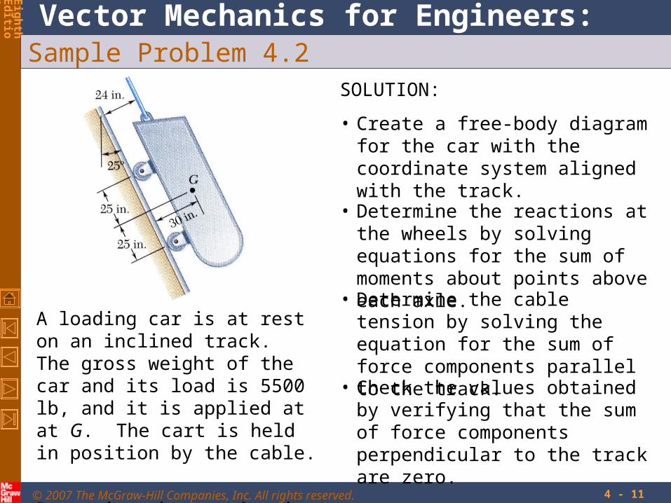
Sample Problem 4.2
A loading car is at rest on an inclined track. The gross weight of the car and its load is 5500 lb, and it is applied at at G. The cart is held in position by the cable.
Determine the tension in the cable and the reaction at each pair of wheels.
SOLUTION:
• Create a free-body diagram for the car with the coordinate system aligned with the track.
• Determine the reactions at the wheels by solving equations for the sum of moments about points above each axle.
• Determine the cable tension by solving the equation for the sum of force components parallel to the track.
• Check the values obtained by verifying that the sum of force components perpendicular to the track are zero.
© 2007 The McGraw-Hill Companies, Inc. All rights reserved.
Vector Mechanics for Engineers: Statics
Eig
ht
hEd
ition
4 - 12
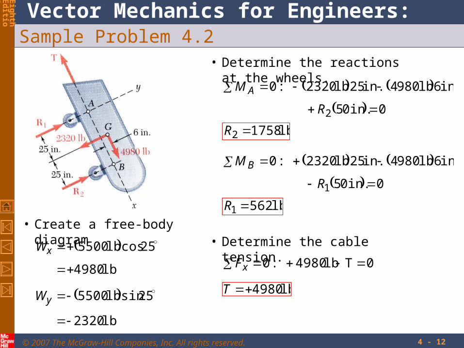
Sample Problem 4.2
• Create a free-body diagram
lb 2320
25sinlb 5500
lb 4980
25coslb 5500
y
x
W
W
• Determine the reactions at the wheels.
00in.5
in.6lb 9804in.25lb 2320:0
2
R
M A
lb 17582 R
00in.5
in.6lb 9804in.25lb 2320:0
1
R
M B
lb 5621 R
• Determine the cable tension.
0Tlb 4980:0 xF
lb 4980T

© 2007 The McGraw-Hill Companies, Inc. All rights reserved.
Vector Mechanics for Engineers: Statics
Eig
ht
hEd
ition
4 - 13
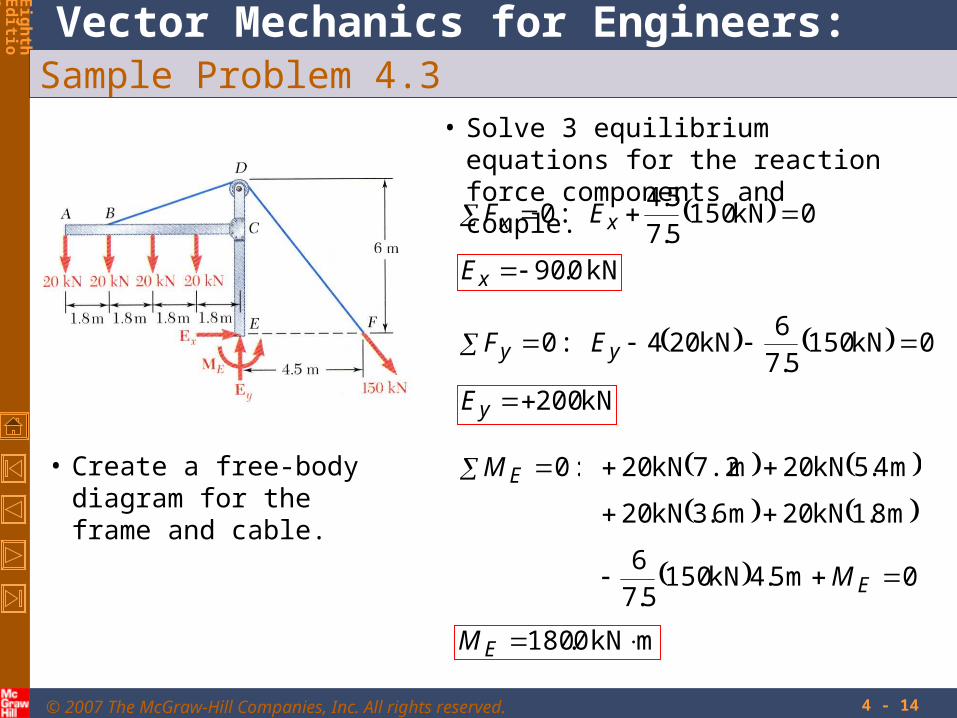
Sample Problem 4.3
The frame supports part of the roof of a small building. The tension in the cable is 150 kN.
Determine the reaction at the fixed end E.
SOLUTION:
• Create a free-body diagram for the frame and cable.
• Solve 3 equilibrium equations for the reaction force components and couple at E.
© 2007 The McGraw-Hill Companies, Inc. All rights reserved.
Vector Mechanics for Engineers: Statics
Eig
ht
hEd
ition
4 - 14
Sample Problem 4.3
• Create a free-body diagram for the frame and cable.
• Solve 3 equilibrium equations for the reaction force components and couple.
0kN1505.7
5.4:0 xx EF
kN 0.90xE
0kN1505.7
6kN204:0 yy EF
kN 200yE
:0EM
0m5.4kN1505.7
6
m8.1kN20m6.3kN20
m4.5kN20m7.2kN20
EM
mkN0.180 EM

© 2007 The McGraw-Hill Companies, Inc. All rights reserved.
Vector Mechanics for Engineers: Statics
Eig
ht
hEd
ition
4 - 15
Equilibrium of a Two-Force Body
• Consider a plate subjected to two forces F1 and F2
• For static equilibrium, the sum of moments about A must be zero. The moment of F2 must be zero. It follows that the line of action of F2 must pass through A.
• Similarly, the line of action of F1 must pass through B for the sum of moments about B to be zero.
• Requiring that the sum of forces in any direction be zero leads to the conclusion that F1 and F2 must have equal magnitude but opposite sense.
© 2007 The McGraw-Hill Companies, Inc. All rights reserved.
Vector Mechanics for Engineers: Statics
Eig
ht
hEd
ition
4 - 16
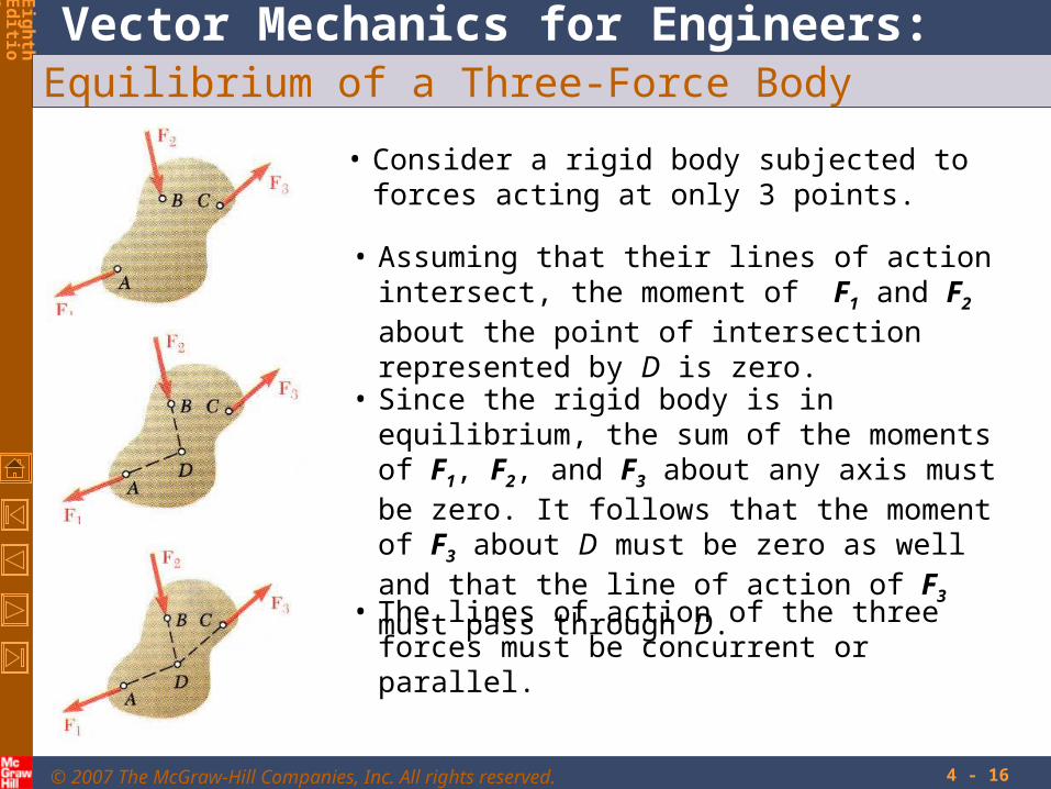
Equilibrium of a Three-Force Body
• Consider a rigid body subjected to forces acting at only 3 points.
• Assuming that their lines of action intersect, the moment of F1 and F2 about the point of intersection represented by D is zero.
• Since the rigid body is in equilibrium, the sum of the moments of F1, F2, and F3 about any axis must be zero. It follows that the moment of F3 about D must be zero as well and that the line of action of F3 must pass through D.
• The lines of action of the three forces must be concurrent or parallel.
© 2007 The McGraw-Hill Companies, Inc. All rights reserved.
Vector Mechanics for Engineers: Statics
Eig
ht
hEd
ition
4 - 17
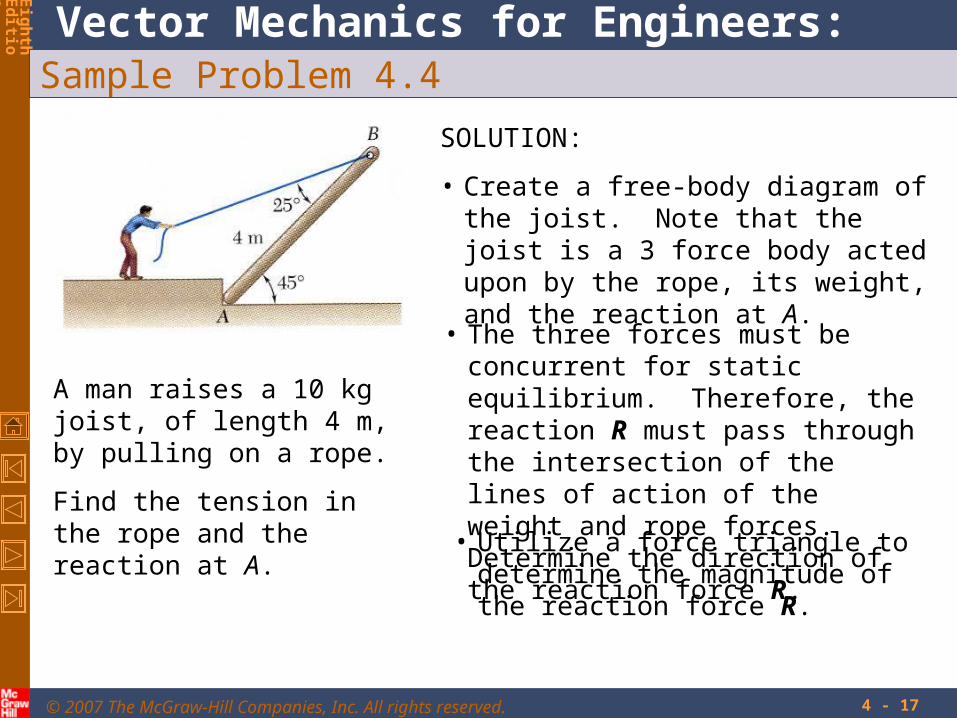
Sample Problem 4.4
A man raises a 10 kg joist, of length 4 m, by pulling on a rope.
Find the tension in the rope and the reaction at A.
SOLUTION:
• Create a free-body diagram of the joist. Note that the joist is a 3 force body acted upon by the rope, its weight, and the reaction at A.
• The three forces must be concurrent for static equilibrium. Therefore, the reaction R must pass through the intersection of the lines of action of the weight and rope forces. Determine the direction of the reaction force R.
• Utilize a force triangle to determine the magnitude of the reaction force R.

© 2007 The McGraw-Hill Companies, Inc. All rights reserved.
Vector Mechanics for Engineers: Statics
Eig
ht
hEd
ition
4 - 18
Sample Problem 4.4
• Create a free-body diagram of the joist.
• Determine the direction of the reaction force R.
6.58
636.1414.1
313.2tan
m 2.313m 515.0828.2
m 515.020tanm 414.1)2545cot(
m 414.1
m828.245cosm445cos
21
AE
CE
BDBFCE
CDBD
AFAECD
ABAF

© 2007 The McGraw-Hill Companies, Inc. All rights reserved.
Vector Mechanics for Engineers: Statics
Eig
ht
hEd
ition
4 - 19
Sample Problem 4.4
• Determine the magnitude of the reaction force R.
38.6sin
N 1.98
110sin4.31sin RT
N 8.147
N9.81
R
T

© 2007 The McGraw-Hill Companies, Inc. All rights reserved.
Vector Mechanics for Engineers: Statics
Eig
ht
hEd
ition
4 - 20
Equilibrium of a Rigid Body in Three Dimensions
• Six scalar equations are required to express the conditions for the equilibrium of a rigid body in the general three dimensional case.
000
000
zyx
zyx
MMM
FFF
• These equations can be solved for no more than 6 unknowns which generally represent reactions at supports or connections.
• The scalar equations are conveniently obtained by applying the vector forms of the conditions for equilibrium,
00 FrMF O

© 2007 The McGraw-Hill Companies, Inc. All rights reserved.
Vector Mechanics for Engineers: Statics
Eig
ht
hEd
ition
4 - 21
Reactions at Supports and Connections for a Three-Dimensional Structure

© 2007 The McGraw-Hill Companies, Inc. All rights reserved.
Vector Mechanics for Engineers: Statics
Eig
ht
hEd
ition
4 - 22
Reactions at Supports and Connections for a Three-Dimensional Structure

© 2007 The McGraw-Hill Companies, Inc. All rights reserved.
Vector Mechanics for Engineers: Statics
Eig
ht
hEd
ition
4 - 23
Sample Problem 4.5
A sign of uniform density weighs 270 lb and is supported by a ball-and-socket joint at A and by two cables.
Determine the tension in each cable and the reaction at A.
SOLUTION:
• Create a free-body diagram for the sign.
• Apply the conditions for static equilibrium to develop equations for the unknown reactions.

© 2007 The McGraw-Hill Companies, Inc. All rights reserved.
Vector Mechanics for Engineers: Statics
Eig
ht
hEd
ition
4 - 24
Sample Problem 4.5
• Create a free-body diagram for the sign.
Since there are only 5 unknowns, the sign is partially constrain. It is free to rotate about the x axis. It is, however, in equilibrium for the given loading.
kjiT
kjiT
rr
rrTT
kjiT
kjiT
rr
rrTT
EC
EC
EC
ECECEC
BD
BD
BD
BDBDBD
72
73
76
32
31
32
7
236
12
848

© 2007 The McGraw-Hill Companies, Inc. All rights reserved.
Vector Mechanics for Engineers: Statics
Eig
ht
hEd
ition
4 - 25
Sample Problem 4.5
• Apply the conditions for static equilibrium to develop equations for the unknown reactions.
0lb1080571.2667.2:
0714.1333.5:
0lb 270ft 4
0:
0lb 270:
0:
0lb 270
72
32
73
31
76
32
ECBD
ECBD
ECEBDBA
ECBDz
ECBDy
ECBDx
ECBD
TTk
TTj
jiTrTrM
TTAk
TTAj
TTAi
jTTAF
kjiA
TT ECBD
lb 22.5lb 101.2lb 338
lb 315lb 3.101
Solve the 5 equations for the 5 unknowns,
26
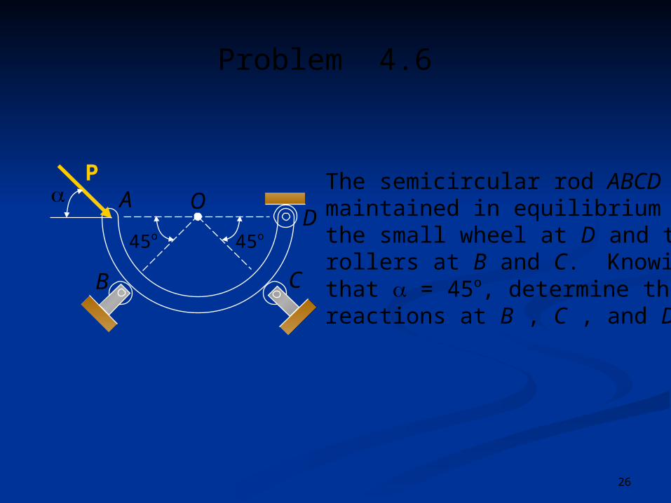
Problem 4.6
45o45o
OD
C
A
B
The semicircular rod ABCD ismaintained in equilibrium bythe small wheel at D and therollers at B and C. Knowingthat = 45o, determine thereactions at B , C , and D.
P

27
45o45o
OD
C
A
B
1. Draw a free-body diagram of the body. This diagram shows the body and all the forces acting on it.
P Solving Problems on Your Own
The semicircular rod ABCD ismaintained in equilibrium bythe small wheel at D and therollers at B and C. Knowingthat = 45o, determine thereactions at B , C , and D.
Problem 4.6
28
45o45o
OD
C
A
B
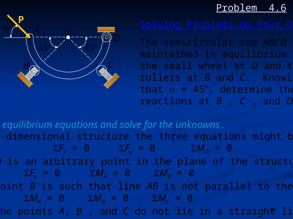
2. Write equilibrium equations and solve for the unknowns. For two-dimensional structure the three equations might be:
Fx = 0 Fy = 0 MO = 0where O is an arbitrary point in the plane of the structureor Fx = 0 MA = 0 MB = 0where point B is such that line AB is not parallel to the y axisor MA = 0 MB = 0 MC = 0where the points A, B , and C do not lie in a straight line.
P Solving Problems on Your Own
The semicircular rod ABCD ismaintained in equilibrium bythe small wheel at D and therollers at B and C. Knowingthat = 45o, determine thereactions at B , C , and D.
Problem 4.6
29
45o45o
OD
C
A
B
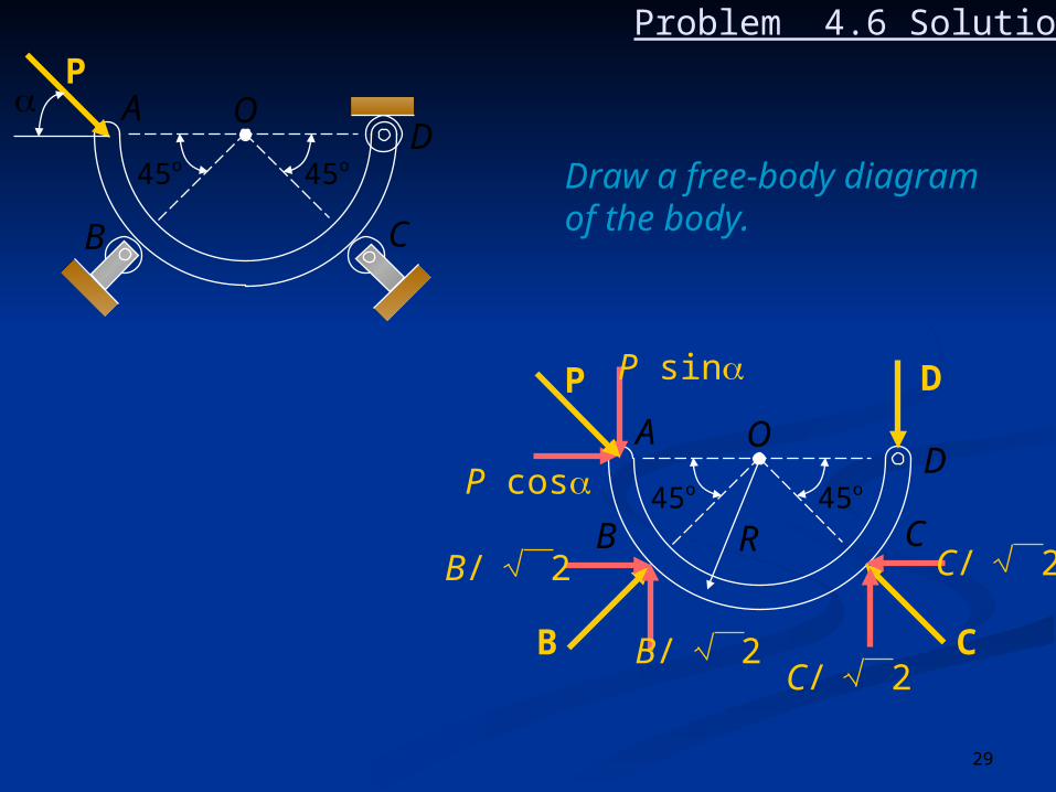
Problem 4.6 Solution
Draw a free-body diagramof the body.
45o45o
OD
C
A
B
P sin
P cos
D
C
R
B
C/ 2
C/ 2B/ 2
B/ 2
P
P

30
Problem 4.6 Solution
45o45o
OD
C
A
B
P sin
P cos
D
C
R
B
C/ 2
C/ 2B/ 2
B/ 2
Write three equilibriumequations and solvefor the unknowns.
+ MO = 0: (P sin) R _ D (R) = 0 D = P sin
+Fx = 0: P cos + B/ 2 _ C / 2 = 0 (2)
+Fy = 0: _P sin + B/ 2 + C / 2 _ P sin = 0
_2P sin + B/ 2 + C / 2 = 0 (3)
P

31
Problem 4.6 Solution
45o45o
OD
C
A
B
P sin
P cos
D
C
R
B
C/ 2
C/ 2B/ 2
B/ 2
(2) + (3) P(cos _ 2sin) + 2 B/ 2 = 0
B = (2sin _ cos) P (4)
(2) _ (3) P(cos + 2sin) _ 2 C/ 2 = 0
C = (2sin + cos) P (5)
22
22
P

32
Problem 4.6 Solution
45o45o
OD
C
A
B
P sin
P cos
D
C
R
B
C/ 2
C/ 2B/ 2
B/ 2For = 45o
sin = cos = 1/ 2
EQ. (4) : B = ( _ ) P = P ; B = P 45o
EQ. (5) : C = ( _ ) P = P ; C = P 45o
EQ. (1) : D = P/ 2 D = P/ 2
32
P
22 2
2 2
1
22 2
2 2
1 32
12
12
33
4 in4 in
2 in
3 in
3 in
A B40 lb20 lb
CD
E
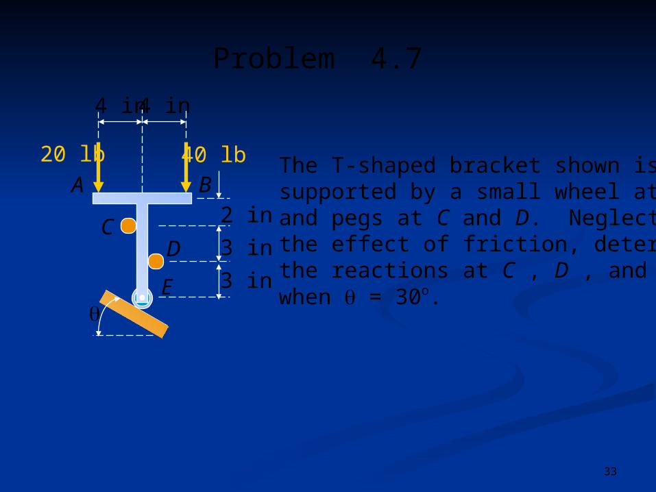
Problem 4.7
The T-shaped bracket shown issupported by a small wheel at Eand pegs at C and D. Neglectingthe effect of friction, determinethe reactions at C , D , and Ewhen = 30o.
34
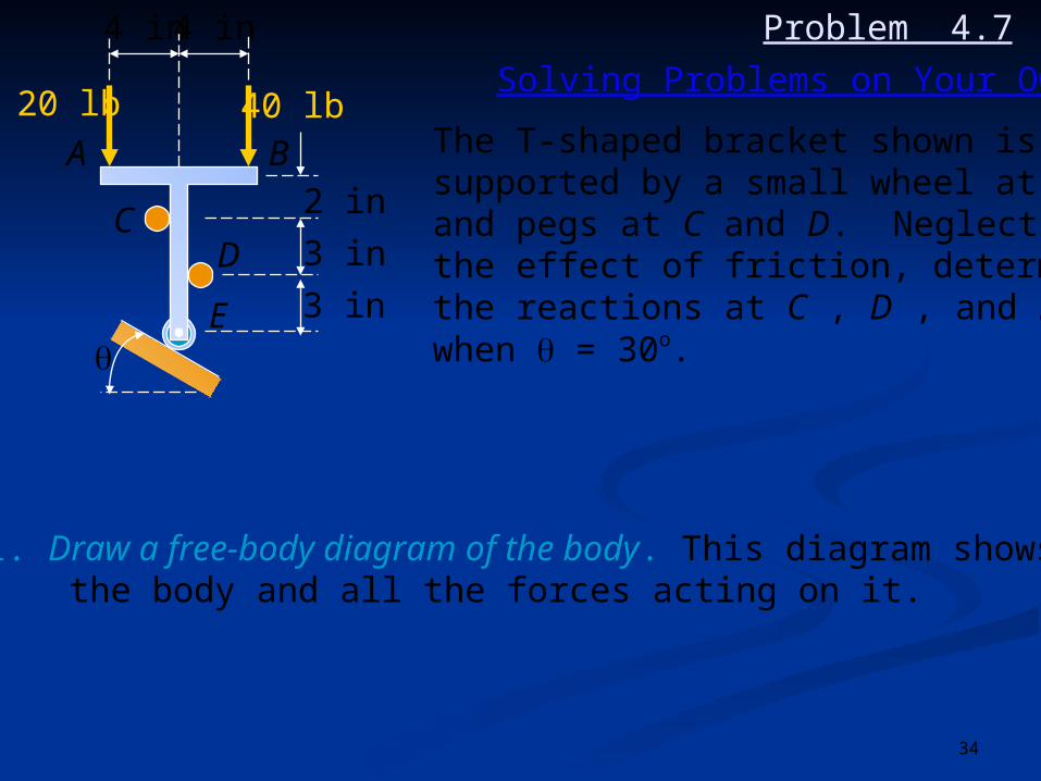
1. Draw a free-body diagram of the body. This diagram shows the body and all the forces acting on it.
4 in4 in
2 in
3 in
3 in
A B40 lb20 lb
CD
E
Solving Problems on Your Own
The T-shaped bracket shown issupported by a small wheel at Eand pegs at C and D. Neglectingthe effect of friction, determinethe reactions at C , D , and Ewhen = 30o.
Problem 4.7

35
2. Write equilibrium equations and solve for the unknowns. For two-dimensional structure the three equations might be:
Fx = 0 Fy = 0 MO = 0where O is an arbitrary point in the plane of the structureor Fx = 0 MA = 0 MB = 0where point B is such that line AB is not parallel to the y axisor MA = 0 MB = 0 MC = 0where the points A, B , and C do not lie in a straight line.
4 in4 in
2 in
3 in
3 in
A B40 lb20 lb
CD
E
Solving Problems on Your Own
The T-shaped bracket shown issupported by a small wheel at Eand pegs at C and D. Neglectingthe effect of friction, determinethe reactions at C , D , and Ewhen = 30o.
Problem 4.7

36
4 in4 in
2 in
3 in
3 in
A B40 lb20 lb
CD
E
4 in4 in
A40 lb20 lb
C2 in
3 in
3 in
B
D
EE
C
D
30o
Draw a free-body diagram of the body.
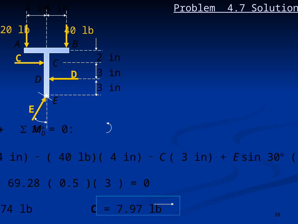
Problem 4.7 Solution

37
4 in4 in
A
C
40 lb20 lb
C2 in
3 in
3 in
B
D
EE
D
30o
Write equilibrium equations andsolve for the unknowns.
Fy = 0: E cos 30o _ 20 _ 40 = 0
E = = 69.28 lb
E = 69.3 lb 60o
60 lb
cos 30o
Problem 4.7 Solution
38
4 in4 in
A
C
40 lb20 lb
C2 in
3 in
3 in
B
D
EE
D
30oMD = 0:
( 20 lb)( 4 in) _ ( 40 lb)( 4 in) _ C ( 3 in) + E sin 30o ( 3 in) = 0
_ 80 _ 3C + 69.28 ( 0.5 )( 3 ) = 0
C = 7.974 lb C = 7.97 lb
Problem 4.7 Solution

39
Problem 4.7 Solution4 in4 in
A
C
40 lb20 lb
C2 in
3 in
3 in
B
D
EE
D
30o
+Fx= 0:
E sin 30o + C _ D = 0
( 69.28 lb )( 0.5 ) + 7.974 lb _ D = 0
D = 42.6 lb

40
Problem 4.8
1.2 m
1.2 m
y
1.5 m
z
x
5 kNA B
C
E
D
1 m2 m
A 3-m pole is supported by aball-and-socket joint at A andby the cables CD and CE.Knowing that the line of actionof the 5-kN force forms anangle =30o with the verticalxy plane, determine (a) thetension in cables CD and CE,(b) the reaction at A.

41
1.2 m
1.2 m
y
1.5 m
z
x
5 kNA B
C
E
D
1 m2 m
1. Draw a free-body diagram of the body. This diagram shows the body and all the forces acting on it.
Solving Problems on Your Own
Problem 4.8
A 3-m pole is supported by aball-and-socket joint at A andby the cables CD and CE.Knowing that the line of actionof the 5-kN force forms anangle =30o with the verticalxy plane, determine (a) thetension in cables CD and CE,(b) the reaction at A.

42
2. Write equilibrium equations and solve for the unknowns. For three-dimensional body the six scalar equations
Fx = 0 Fy = 0 Fz = 0 Mx = 0 My = 0 Mz = 0
should be used and solved for six unknowns. These equationscan also be written as
F = 0 MO = (r x F ) = 0where F are the forces and r are position vectors.
1.2 m
1.2 m
y
1.5 m
z
x
5 kNA B
C
E
D
1 m2 m
A 3-m pole is supported by a ball-and-socket joint at A and by thecables CD and CE. Knowing thatthe line of actionof the 5-kN forceforms an angle =30o with thevertical xy plane, determine (a)the tension in cables CD and CE,(b) the reaction at A.
Solving Problems on Your OwnProblem 4.8

43
Problem 4.8 Solution
Draw a free-body diagramof the body.
1.2 m
1.2 m
y
1.5 m
z
x
5 kNA B
C
E
D
1 m2 m
1.2 m
1.2 m
y
1.5 m
z
xA B
C
E
D
1 m2 m
30o
5 kN
TCETCD
Ay j
Ax i
Az k

44
Write equilibrium equationsand solve for the unknowns.
1.2 m
1.2 m
y
1.5 m
z
xA B
C
E
D
1 m2 m
30o
5 kN
TCETCD
Ay j
Ax i
Az k
5 unknowns and 6 equations ofequilibrium, but equilibrium ismaintained, MAC = 0 .
rB/A = 2 i rC/A = 3 i
Load at B, FB = _ ( 5 cos 30o ) j + ( 5 sin 30o ) k = _ 4.33 j + 2.5 k
CD = _ 3 i+ 1.5 j + 1.2 k CD = 3.562 m
TCD = TCD = (_ 3 i + 1.5 j + 1.2 k)
TCE = TCE = (_ 3 i + 1.5 j _ 1.2 k)
CDCD
TCD
3.562
TCD
3.562CECE
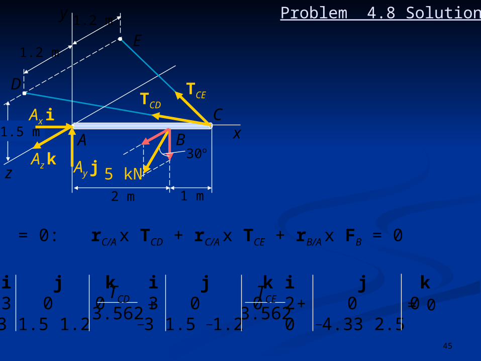
Problem 4.8 Solution
45
1.2 m
1.2 m
y
1.5 m
z
xA B
C
E
D
1 m2 m
30o
5 kN
TCETCD
Ay j
Ax i
Az k
MA = 0: rC/A x TCD + rC/A x TCE + rB/A x FB = 0
i j k 3 0 0_3 1.5 1.2
i j k 3 0 0_3 1.5 _1.2
i j k2 0 00 _4.33 2.5
TCD
3.562 +TCE
3.562+ = 0
Problem 4.8 Solution

46
1.2 m
1.2 m
y
1.5 m
z
xA B
C
E
D
1 m2 m
30o
5 kN
TCETCD
Ay j
Ax i
Az k
Equate coefficients of unit vectors to zero.
j: _3.6 + 3.6 _ 5 = 0
_3.6 TCD+3.6 TCE_17.81 = 0 (1)
TCD
3.562TCE
3.562
k: 4.5 + 4.5 _ 8.66 = 0
4.5 TCD+4.5 TCE = 30.85 (2)
TCD
3.562TCE
3.562
(2) + 1.25 (1): 9TCE _ 53.11 = 0 ; TCE = 5.90 kN
Eq. (1): _3.6TCD + 3.6 (5.902) _ 17.81 = 0 TCD = 0.954 kN
Problem 4.8 Solution
47
1.2 m
1.2 m
y
1.5 m
z
xA B
C
E
D
1 m2 m
30o
5 kN
TCETCD
Ay j
Ax i
Az k
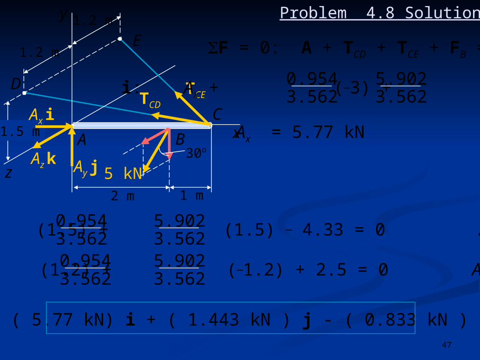
F = 0: A + TCD + TCE + FB = 0
i: Ax + (_3) + (_3) = 0
Ax = 5.77 kN
3.5620.954
3.5625.902
j: Ay + (1.5) + (1.5) _ 4.33 = 0 Ay = 1.443 kN3.5620.954
3.5625.902
k: Az + (1.2) + (_1.2) + 2.5 = 0 Az = _ 0.833 kN3.5620.954
3.5625.902
A = ( 5.77 kN) i + ( 1.443 kN ) j - ( 0.833 kN ) k
Problem 4.8 Solution
48
A
B
C
a
20 in
10 in60 lb
Problem 4.9
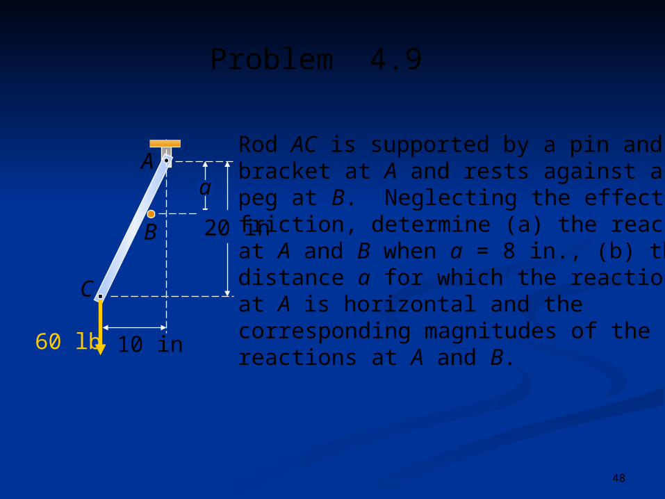
Rod AC is supported by a pin andbracket at A and rests against apeg at B. Neglecting the effect offriction, determine (a) the reactionsat A and B when a = 8 in., (b) thedistance a for which the reactionat A is horizontal and thecorresponding magnitudes of thereactions at A and B.

49
A
B
C
a
20 in
10 in60 lb
1. Draw a free-body diagram of the body. This diagram shows the body and all the forces acting on it.
Solving Problems on Your Own
Problem 4.9
Rod AC is supported by a pin andbracket at A and rests against apeg at B. Neglecting the effect offriction, determine (a) the reactionsat A and B when a = 8 in., (b) thedistance a for which the reactionat A is horizontal and thecorresponding magnitudes of thereactions at A and B.
50
A
B
C
a
20 in
10 in60 lb
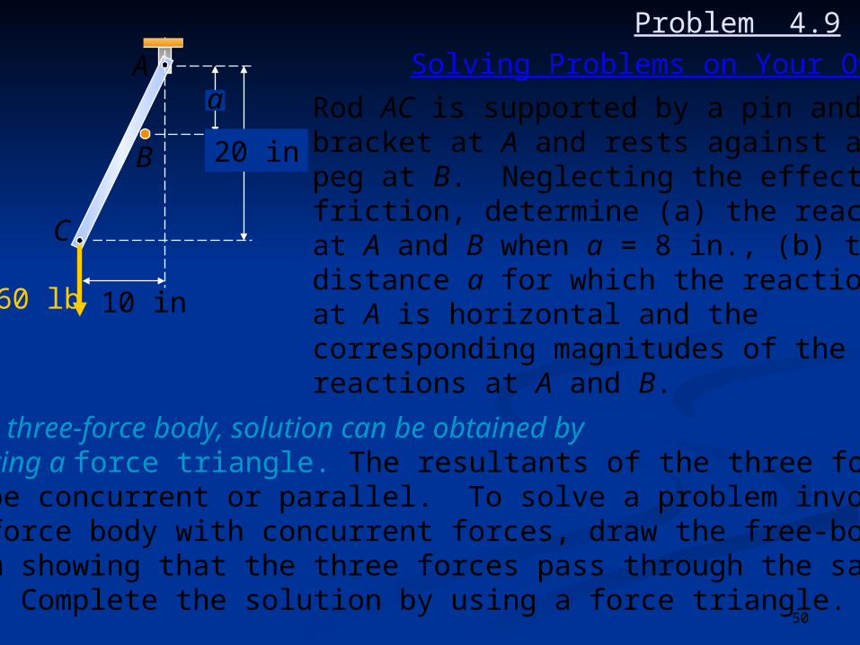
2. For a three-force body, solution can be obtained byconstructing a force triangle. The resultants of the three forces must be concurrent or parallel. To solve a problem involving athree-force body with concurrent forces, draw the free-bodydiagram showing that the three forces pass through the samepoint. Complete the solution by using a force triangle.
Solving Problems on Your Own
Problem 4.9
Rod AC is supported by a pin andbracket at A and rests against apeg at B. Neglecting the effect offriction, determine (a) the reactionsat A and B when a = 8 in., (b) thedistance a for which the reactionat A is horizontal and thecorresponding magnitudes of thereactions at A and B.

51
Problem 4.9 Solution
Draw a free-body diagramof the body.
A
B
C
a
20 in
10 in60 lb
C
10 in60 lb
A
8 in
12 inBB
A
21
GD
F E
10 in
(a) a = 8 in
tan =
= 26.57o
12

52
C
10 in60 lb
A
8 in
12 inBB
A
21
GD
F E
10 in
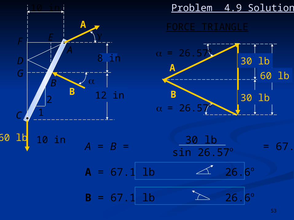
3 - FORCE BODY
Reaction at A passes through Dwhere B and 60-lb load intersect
AE = EB = (8) = 4 in.
EF = BG = 10 _ 4 = 6 in
DG = BG = (6) = 3 in.
FD = FG _ DG = 8 _ 3 = 5 in.
Tan = = ; = 26.57o
12
12
12
12
FDAF
510
Construct a force triangle.
Problem 4.9 Solution
53
C
10 in60 lb
A
8 in
12 inBB
A
21
GD
F E
10 in
FORCE TRIANGLE
60 lb
30 lb
30 lb
= 26.57o
= 26.57o
A
B
A = B = = 67.08 lb
A = 67.1 lb 26.6o
B = 67.1 lb 26.6o
sin 26.57o30 lb
Problem 4.9 Solution
54
A
B
C
a
20 in
10 in60 lb
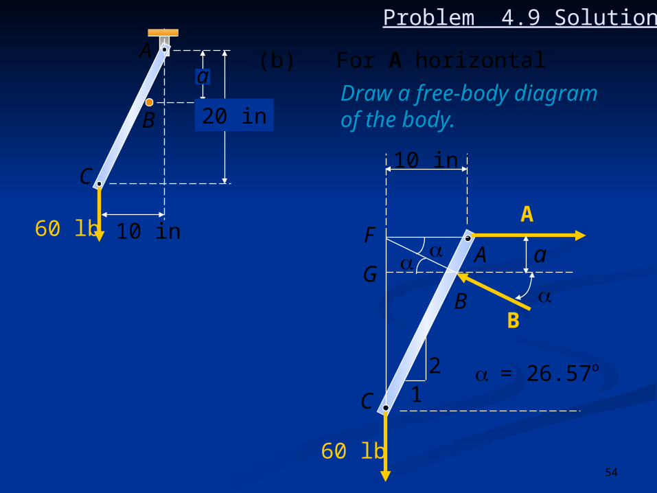
Draw a free-body diagramof the body.
(b) For A horizontal
C
60 lb
A
B
B
A
21
G
F
10 in
a
= 26.57o
Problem 4.9 Solution

55
C
60 lb
A
B
B
A
21
G
F
10 in
a
= 26.57o
Problem 4.9 Solution
Construct a force triangle.
ABF : BF = AF cos
BFG : FG = BF sin
a = FG = AF cos sin
a = (10 in.) cos 26.57o sin 26.57o
a = 4.00 in.
56
C
60 lb
A
B
B
A
21
G
F
10 in
a
= 26.57o
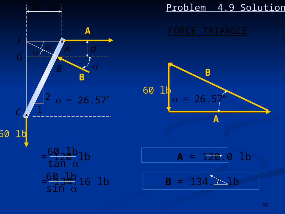
Problem 4.9 Solution
FORCE TRIANGLE
60 lb
A
B
= 26.57o
A = = 120 lb A = 120.0 lb
B = = 134.16 lb B = 134.2 lb 26.6o
tan 60 lb
sin 60 lb

57
DCBA
aaa
30o30o
P
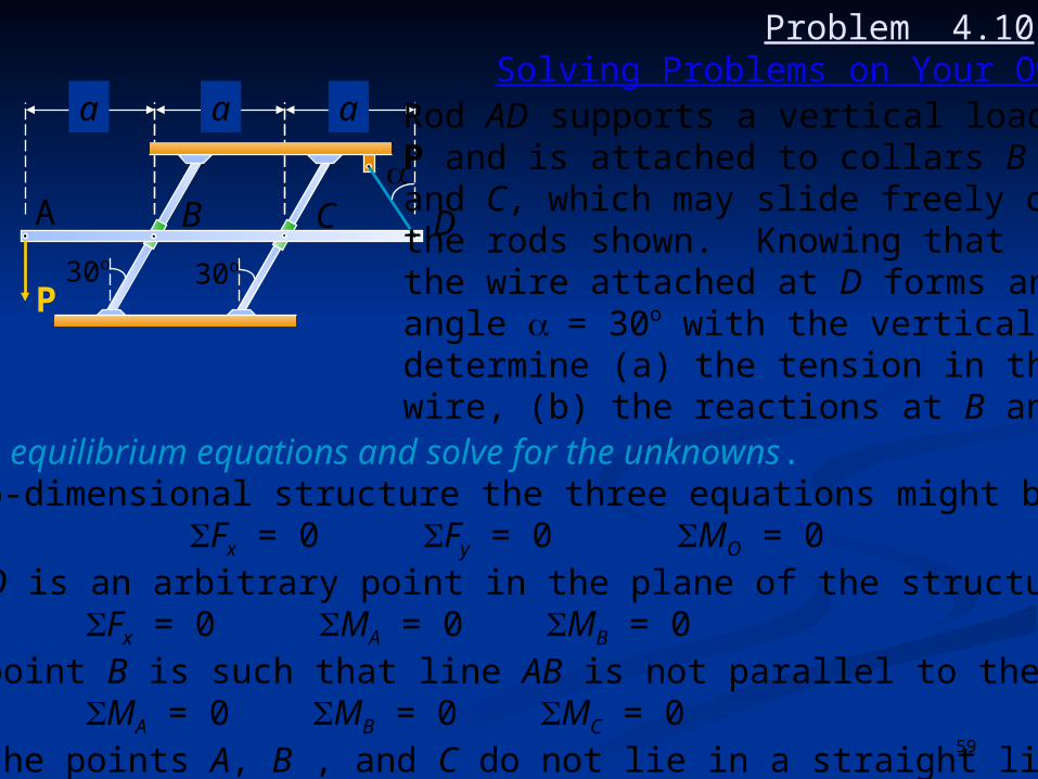
Problem 4.10
Rod AD supports a vertical loadP and is attached to collars Band C, which may slide freely onthe rods shown. Knowing thatthe wire attached at D forms anangle = 30o with the vertical,determine (a) the tension in thewire, (b) the reactions at B and C.

58
DCBA
aaa
30o30o
P
1. Draw a free-body diagram of the body. This diagram shows the body and all the forces acting on it.
Solving Problems on Your Own
Rod AD supports a vertical loadP and is attached to collars Band C, which may slide freely onthe rods shown. Knowing thatthe wire attached at D forms anangle = 30o with the vertical,determine (a) the tension in thewire, (b) the reactions at B and C.
Problem 4.10
59
2. Write equilibrium equations and solve for the unknowns. For two-dimensional structure the three equations might be:
Fx = 0 Fy = 0 MO = 0where O is an arbitrary point in the plane of the structureor Fx = 0 MA = 0 MB = 0where point B is such that line AB is not parallel to the y axisor MA = 0 MB = 0 MC = 0where the points A, B , and C do not lie in a straight line.
DCBA
aaa
30o30o
P
Solving Problems on Your OwnRod AD supports a vertical loadP and is attached to collars Band C, which may slide freely onthe rods shown. Knowing thatthe wire attached at D forms anangle = 30o with the vertical,determine (a) the tension in thewire, (b) the reactions at B and C.
Problem 4.10

60
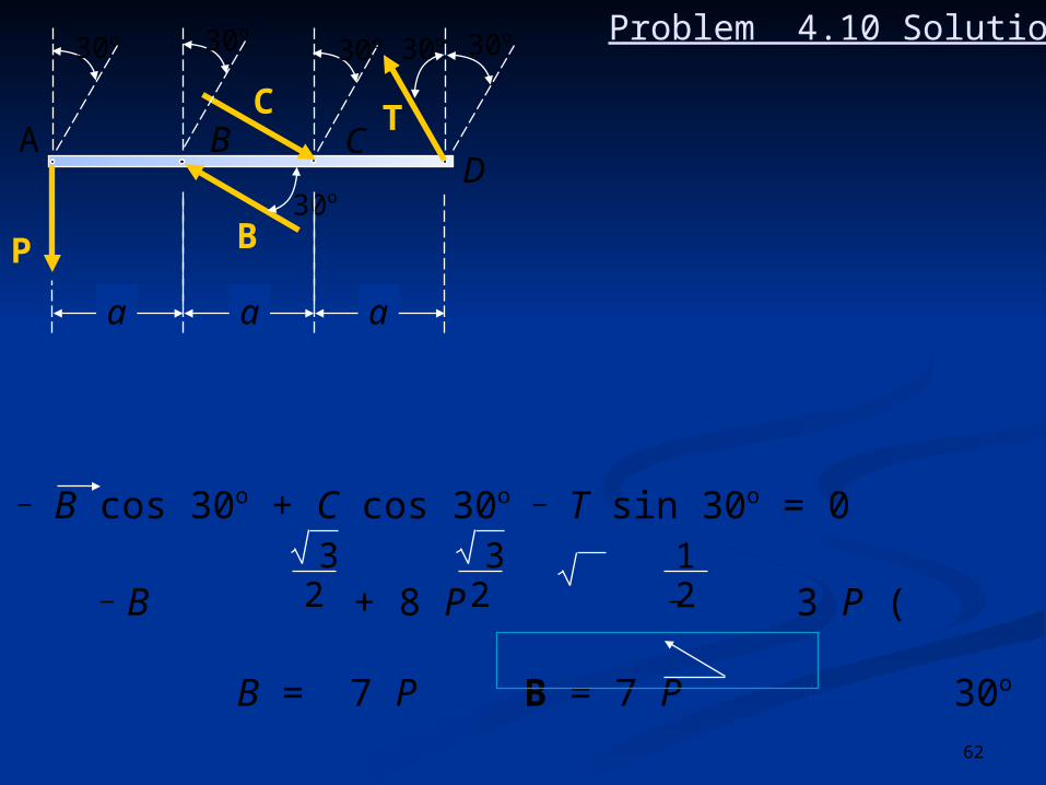
Problem 4.10 Solution
Draw a free-body diagramof the body.
DCBA
aaa
30o30o
P
DCBA
30o
30o
P
aaa
C
B
30o30o30o30o
T

61
Write equilibrium equationsand solve for the unknowns.
Problem 4.10 Solution
DCBA
30o
30o
P
aaa
C
B
30o30o30o30o
T
F = 0: _ P cos 30o + T cos 60o = 0
T = P = P T = 3 P
30o
cos 30o
cos 60o
3 / 21 / 2
+ MB = 0: P a _ (C sin 30o) a + T cos 30o (2a) = 0
P a _ ( C ) a + 3 P ( ) 2a = 0
_ C + (1 + 3) P = 0; C = 8 P C = 8 P 30o
12
32
12
62
DCBA
30o
30o
P
aaa
C
B
30o30o30o30o
T
+F = 0: _ B cos 30o + C cos 30o _ T sin 30o = 0
_ B + 8 P _ 3 P ( ) = 0;
B = 7 P B = 7 P 30o
32
32
12
Problem 4.10 Solution