cdmaremoteradiounit-8860 technical manual · declaration of rohs compliance...
TRANSCRIPT

ZXSDR R8860CDMA Remote Radio Unit-8860
Technical Manual
ZTE CORPORATIONNO. 55, Hi-tech Road South, ShenZhen, P.R.ChinaPostcode: 518057Tel: +86-755-26771900Fax: +86-755-26770801URL: http://ensupport.zte.com.cnE-mail: [email protected]

LEGAL INFORMATIONCopyright © 2011 ZTE CORPORATION.
The contents of this document are protected by copyright laws and international treaties. Any reproduction or
distribution of this document or any portion of this document, in any form by any means, without the prior written
consent of ZTE CORPORATION is prohibited. Additionally, the contents of this document are protected by
contractual confidentiality obligations.
All company, brand and product names are trade or service marks, or registered trade or service marks, of ZTE
CORPORATION or of their respective owners.
This document is provided “as is”, and all express, implied, or statutory warranties, representations or conditions
are disclaimed, including without limitation any implied warranty of merchantability, fitness for a particular purpose,
title or non-infringement. ZTE CORPORATION and its licensors shall not be liable for damages resulting from the
use of or reliance on the information contained herein.
ZTE CORPORATION or its licensors may have current or pending intellectual property rights or applications
covering the subject matter of this document. Except as expressly provided in any written license between ZTE
CORPORATION and its licensee, the user of this document shall not acquire any license to the subject matter
herein.
ZTE CORPORATION reserves the right to upgrade or make technical change to this product without further notice.
Users may visit ZTE technical support website http://ensupport.zte.com.cn to inquire related information.
The ultimate right to interpret this product resides in ZTE CORPORATION.
Revision History
Revision No. Revision Date Revision Reason
R1.0 08/30/2010 First Edition
Serial Number: SJ-20100722143906-001
Publishing Date: 08/30/2010

Declaration of RoHSComplianceTo minimize the environmental impact and take more responsibility to the earth we live,this document shall serve as formal declaration that ZXSDR R8860 manufactured byZTE CORPORATION are in compliance with the Directive 2002/95/EC of the EuropeanParliament - RoHS (Restriction of Hazardous Substances) with respect to the followingsubstances:
l Lead (Pb)l Mercury (Hg)l Cadmium (Cd)l Hexavalent Chromium (Cr (VI))l PolyBrominated Biphenyls (PBB’s)l PolyBrominated Diphenyl Ethers (PBDE’s)
…
The ZXSDR R8860 manufactured by ZTE CORPORATION meet the requirements of EU 2002/95/EC;
however, some assemblies are customized to client specifications. Addition of specialized,
customer-specified materials or processes which do not meet the requirements of EU 2002/95/EC
may negate RoHS compliance of the assembly. To guarantee compliance of the assembly, the
need for compliant product must be communicated to ZTE CORPORATION in written form. This
declaration is issued based on our current level of knowledge. Since conditions of use are outside
our control, ZTE CORPORATION makes no warranties, express or implied, and assumes no liability
in connection with the use of this information.
I

II

FCC & IC STATEMENTThis device complies with part 15 of the FCC Rules. Operation is subject to the followingtwo conditions:
1. This device may not cause harmful interference.2. This device must accept any interference received, including interference that may
cause undesired operation.
This Class[A] digital apparatus complies with Canadian ICES-003.
Note:
Working with the equipment while in operation, may expose the technician to RFelectromagnetic fields that exceed FCC rules for human exposure. Visit the FCCwebsite at www.fcc.gov/oet/rfsafety to learn more about the effects of exposure to RFelectromagnetic fields.
Changes or modifications to this unit not expressly approved by the party responsible forcompliance will void the user’s authority to operate the equipment. Any change to theequipment will void FCC and IC grant.
This equipment has been tested and found to comply with the limits for a Class A digitaldevice, pursuant to the FCC and IC Rules. This equipment generates, uses and canradiate radio frequency energy and, if not installed and used in accordance with theinstructions, may cause harmful interference to radio communications. However, there isno guarantee that interference will not occur in a particular installation.
I

II
RF Exposure Information forPMRThe product generates RF electromagnetic energy during transmit mode.
This radio is designed for and classified as “Occupational Use Only”, meaning it mustbe used only during the course of employment by individuals aware of the hazards, andthe ways to minimize such hazards. This radio is NOT intended for use by the “GeneralPopulation” in an uncontrolled environment.
This radio has been tested and complies with the FCCRF exposure limits for “OccupationalUse Only”.
In addition, the product complies with the following Standards and Guidelines with regardto RF energy and electromagnetic energy levels and evaluation of such levels for exposureto humans:
1. FCC OET Bulletin 65 Edition 97-01 Supplement C, Evaluating Compliance with FCCGuidelines for Human Exposure to Radio Frequency Electromagnetic Fields.
2. tAmerican National Standards Institute (C95.1-1992), IEEE Standard for Safety Levelswith Respect to Human Exposure to Radio Frequency Electromagnetic Fields, 3 kHzto 300 GHz.
3. American National Standards Institute (C95.3-1992), IEEE Recommended Practicefor the Measurement of Potentially Hazardous Electromagnetic Fields– RF andMicrowave.
4. The following accessories are authorized for use with this product. Use of accessoriesother than those (listed in the instruction) specified may result in RF exposure levelsexceeding the FCC requirements for wireless RF exposure.
I

II

About This ManualPurpose
ZXSDR R8860 is an outdoor remote RF unit. Composing an integrated BTS, ZXSDRR8860 and ZXSDRR8860 implement wireless transmission within coverage areas, controlof wireless channel as well as communication with BSC.
This manual provides ZXSDR R8860 product overview, which will help the readersknow the product’s function, principle, specification, features, cabinet, modules, externalinterfaces and cables.
Intended Audience
This document is intended for engineers and technicians who perform operation activitiesZXSDR R8860.
l Engineering techniciansl Equipment installation engineersl Equipment commissioning engineers
Prerequisite Skill and Knowledge
To use this document effectively, users should have a general understanding of ZXSDRR8860 equipment and its components. Familiarity with the following is helpful:
l ZXSDR R8860 hardware structurel Basic software knowledge
What is in This Manual
This manual contains the following chapters.
Chapter Summary
Chapter 1 Product
Overview
This chapter describes product’s function, specification, features and technical
specifications.
Chapter 2
Hardware
Description
This chapter describes product’s module function and work principle, cables’s
structure and main antenna system.
Chapter 3
Protocol Interface
Description
This chapter describes product’s protocol interfaces.
Conventions
ZTE documents employ the following typographical conventions.
I
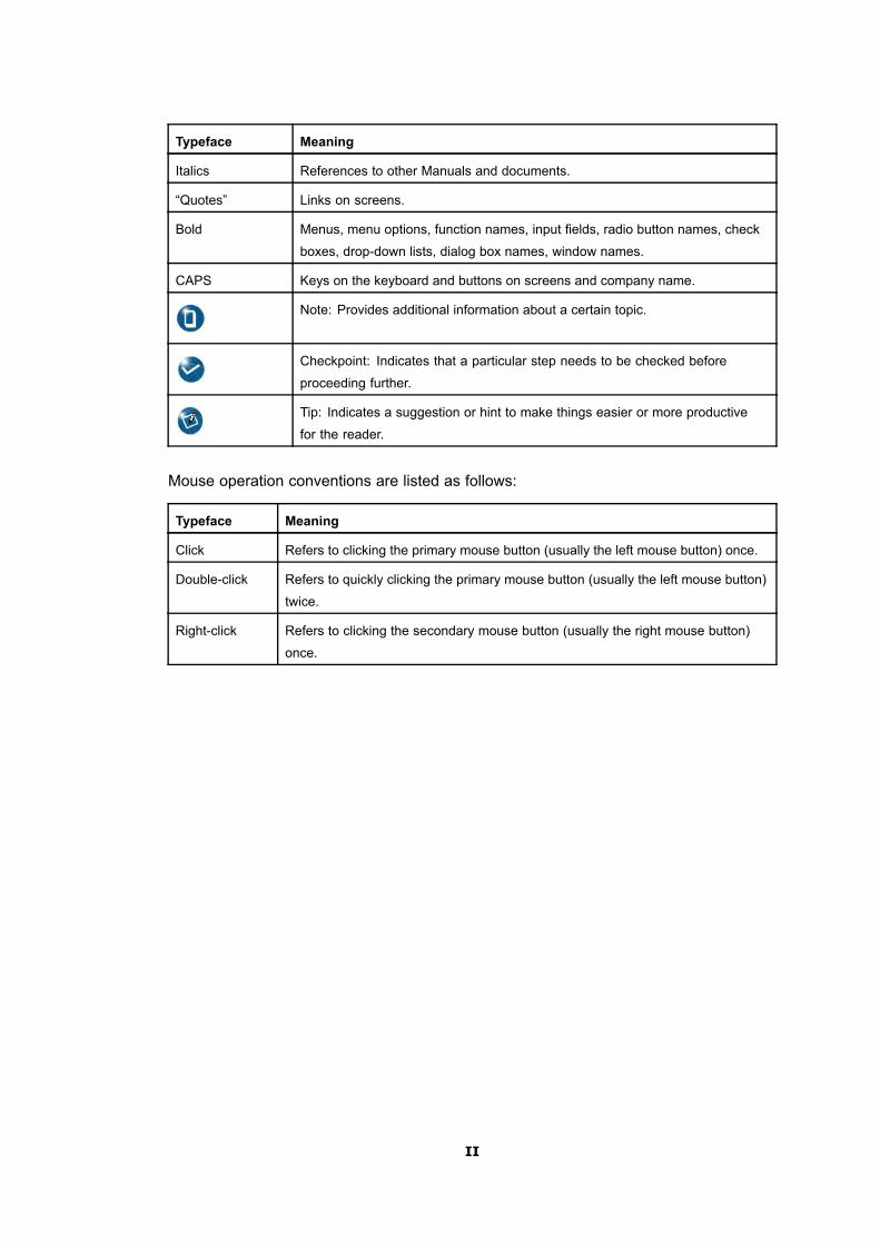
Typeface Meaning
Italics References to other Manuals and documents.
“Quotes” Links on screens.
Bold Menus, menu options, function names, input fields, radio button names, check
boxes, drop-down lists, dialog box names, window names.
CAPS Keys on the keyboard and buttons on screens and company name.
Note: Provides additional information about a certain topic.
Checkpoint: Indicates that a particular step needs to be checked before
proceeding further.
Tip: Indicates a suggestion or hint to make things easier or more productive
for the reader.
Mouse operation conventions are listed as follows:
Typeface Meaning
Click Refers to clicking the primary mouse button (usually the left mouse button) once.
Double-click Refers to quickly clicking the primary mouse button (usually the left mouse button)
twice.
Right-click Refers to clicking the secondary mouse button (usually the right mouse button)
once.
II

ContentsDeclaration of RoHS Compliance ................................................................. I
FCC & IC STATEMENT ................................................................................... I
RF Exposure Information for PMR................................................................ I
About This Manual ......................................................................................... I
Chapter 1 Product Overview ..................................................................... 1-11.1 Distributed ZTE BTS Solution.............................................................................. 1-1
1.2 Position in the Network ....................................................................................... 1-2
1.3 Appearance ....................................................................................................... 1-3
1.4 Functions........................................................................................................... 1-4
1.5 Features ............................................................................................................ 1-5
1.6 External Interfaces ............................................................................................. 1-6
1.7 Application Scenarios ......................................................................................... 1-7
1.8 Work Principle.................................................................................................. 1-10
1.8.1 System Structure.................................................................................... 1-10
1.8.2 Signal Flow............................................................................................ 1-10
1.9 Networking .......................................................................................................1-11
1.9.1 Baseband-RF Interface Networking ..........................................................1-11
1.9.2 Cascade Networking .............................................................................. 1-12
1.9.3 Frequency Extension Networking ............................................................ 1-12
1.10 Equipment Management Modes ...................................................................... 1-13
1.10.1 OMC Mode .......................................................................................... 1-13
1.10.2 LMT Mode ........................................................................................... 1-14
1.11 Technical Indices ............................................................................................ 1-15
1.11.1 Engineering Indices .............................................................................. 1-15
1.11.2 Performance Indices ............................................................................. 1-16
1.11.3 RF Indicies........................................................................................... 1-17
1.12 Compliance Standards.................................................................................... 1-18
Chapter 2 Hardware Descriptions............................................................. 2-12.1 Cabinet.............................................................................................................. 2-1
2.1.1 External Structure .................................................................................... 2-1
2.1.2 Indoor Structure ....................................................................................... 2-2
2.1.3 Ventilation and Heat-dissipation Principles ................................................. 2-3
2.2 Modules............................................................................................................. 2-3
I

2.2.1 Modules List ............................................................................................ 2-3
2.2.2 Filter LNA (FL) ......................................................................................... 2-3
2.2.3 Transceiver (TR) ...................................................................................... 2-4
2.2.4 Power Amplifier (PA) ................................................................................ 2-5
2.2.5 Power...................................................................................................... 2-5
2.3 External Cables.................................................................................................. 2-5
2.3.1 DC Power Cable ...................................................................................... 2-5
2.3.2 Grounding Cable ...................................................................................... 2-6
2.3.3 AISG Control Cable.................................................................................. 2-6
2.3.4 Optical Fiber Cable................................................................................... 2-7
2.3.5 Environment Monitoring Cable .................................................................. 2-7
2.3.6 Carrier Sector Extension Cable ................................................................. 2-8
2.3.7 RF Jumper Cable ..................................................................................... 2-9
2.4 Main Antenna Feeder System ........................................................................... 2-10
2.4.1 Main Antenna Feeder System Structure................................................... 2-10
2.4.2 Antenna................................................................................................. 2-14
2.4.3 Feeder Structure .................................................................................... 2-15
Chapter 3 Protocol Interface Description................................................. 3-13.1 Network Reference Model................................................................................... 3-1
3.2 Um Interface ...................................................................................................... 3-2
3.3 Baseband—RF Interface .................................................................................... 3-6
Figures............................................................................................................. I
Tables ............................................................................................................ III
Glossary .........................................................................................................V
II

Chapter 1Product OverviewTable of Contents
Distributed ZTE BTS Solution.....................................................................................1-1Position in the Network...............................................................................................1-2Appearance................................................................................................................1-3Functions ...................................................................................................................1-4Features.....................................................................................................................1-5External Interfaces .....................................................................................................1-6Application Scenarios.................................................................................................1-7Work Principle ..........................................................................................................1-10Networking ...............................................................................................................1-11Equipment Management Modes...............................................................................1-13Technical Indices......................................................................................................1-15Compliance Standards .............................................................................................1-18
1.1 Distributed ZTE BTS SolutionIn order to provide more competitive communication devices and solutions for customers,ZTE provides distributed ZTE CDMA2000 BBU +RRU solution to accomplish servicefunctions of CDMA2000 BTSs.
Figure 1-1 shows the architecture of distributed ZTE BTS solution.
Figure 1-1 Distributed ZTE BTS Solution
1-1
SJ-20100722143906-001|08/30/2010 ZTE Proprietary and Confidential
ZXSDR R8860 Technical Manual
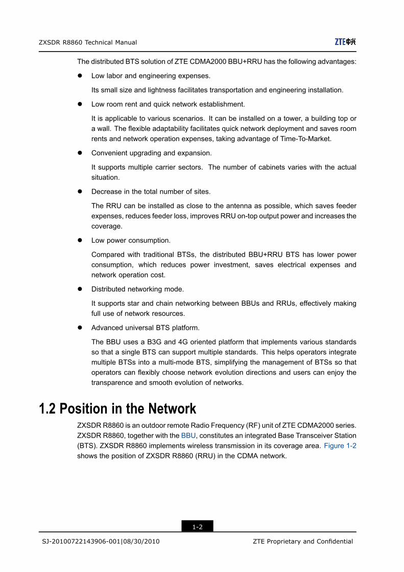
The distributed BTS solution of ZTE CDMA2000 BBU+RRU has the following advantages:
l Low labor and engineering expenses.
Its small size and lightness facilitates transportation and engineering installation.
l Low room rent and quick network establishment.
It is applicable to various scenarios. It can be installed on a tower, a building top ora wall. The flexible adaptability facilitates quick network deployment and saves roomrents and network operation expenses, taking advantage of Time-To-Market.
l Convenient upgrading and expansion.
It supports multiple carrier sectors. The number of cabinets varies with the actualsituation.
l Decrease in the total number of sites.
The RRU can be installed as close to the antenna as possible, which saves feederexpenses, reduces feeder loss, improves RRU on-top output power and increases thecoverage.
l Low power consumption.
Compared with traditional BTSs, the distributed BBU+RRU BTS has lower powerconsumption, which reduces power investment, saves electrical expenses andnetwork operation cost.
l Distributed networking mode.
It supports star and chain networking between BBUs and RRUs, effectively makingfull use of network resources.
l Advanced universal BTS platform.
The BBU uses a B3G and 4G oriented platform that implements various standardsso that a single BTS can support multiple standards. This helps operators integratemultiple BTSs into a multi-mode BTS, simplifying the management of BTSs so thatoperators can flexibly choose network evolution directions and users can enjoy thetransparence and smooth evolution of networks.
1.2 Position in the NetworkZXSDR R8860 is an outdoor remote Radio Frequency (RF) unit of ZTE CDMA2000 series.ZXSDR R8860, together with the BBU, constitutes an integrated Base Transceiver Station(BTS). ZXSDR R8860 implements wireless transmission in its coverage area. Figure 1-2shows the position of ZXSDR R8860 (RRU) in the CDMA network.
1-2
SJ-20100722143906-001|08/30/2010 ZTE Proprietary and Confidential

Chapter 1 Product Overview
Figure 1-2 ZXSDR R8860 Position in the Network
1.3 AppearanceThe ZXSDR R8860 cabinet is plated with materials that are applicable to outdoorenvironments. Figure 1-3 shows the ZXSDR R8860 cabinet appearance.
Figure 1-3 ZXSDR R8860 Cabinet Appearance
1-3
SJ-20100722143906-001|08/30/2010 ZTE Proprietary and Confidential

ZXSDR R8860 Technical Manual
1.4 FunctionsTable 1-1 describes ZXSDR R8860 functions.
Table 1-1 ZXSDR R8860 Functions
Function Description
Band:
800 MHz Band Class 0
1900MHz PCS
450MHz (Band Class 5)
850MHz (Band Class 10)
420MHz (Band Class 5)
2100MHz (Band Class 6)
AWS Band Class 15
RF modulation/demodulation
RF transceiver duplexer
Low noise amplification for received RF signal
Amplification for transmitted RF signal
RF
RF transceiver
Baseband-RF interface: compliant with Common Public Radio
Interface (CPRI) protocol
Air interface: compliant with IS-2000 Release A and IS-856-AInterface
Local debugging and maintenance interface: Ethernet
Support for the remote application of the RRU; networking
modes are involved into star and chain.
Combined RF cabinets (diversity output/input)Networking
Support for the cascading networking mode of RRU, the highest
up to 4 levels
Input power undervoltage/overvoltage alarm
Output power undervoltage/overvoltage alarm
Power overcurrent alarm
Environment temperature alarm
External RS-485 monitoring interface
Environment Monitoring
External monitoring extension interface: 4 input dry contacts
1-4
SJ-20100722143906-001|08/30/2010 ZTE Proprietary and Confidential

Chapter 1 Product Overview
Function Description
Electronic label
Power query: baseband power, RF power, and antenna output
power
Automatic calibration
RSSI query
Reverse spectrum query: querying the reverse received signal
spectrum of each carrier
monitoring alarm for antenna standing wave ratio
Equipment maintenance and
testing
Power amplification control and protection: over-power,
over-temperature, and standing wave alarm.
1.5 FeaturesThe features of the ZXSDR R8860 are as follows:
l Small Size
The ZXSDR R8860 occupies a small area, saving room rent expenses.
à Dimension of a single ZXSDR R8860 cabinet without handle (H x W x D): 500mm × 320 mm × 172 mm. When installed indoors, it requires a small installationarea.
à ZXSDR R8860 can also be installed outdoors, supporting pole-mount,wall-mount, and Gantry mount installations. Except for the Gantry mountinstallation, which occupies minimum floor space, the other cases almost doesnot occupy any floor space.
l Light Weight
A single ZXSDR R8860 cabinet weighs 22 kg so it is easy to transport and install,requiring low manpower and engineering costs.
l Optical fiber Support
ZXSDR R8860 supports optical fiber installation on a tower. ZXSDR R8860 and theBBU can be connected via fibers. One pair of fibers can support a large number ofsectors which greatly lowers antenna feeder cost and engineering expenses
l Low Power Consumption
Lower power consumption imposes lower power supply requirements, saving powerconstruction costs and daily power charges.
à Power consumption: (<350W, -48 V DC)
à Less RF power loss because the installation of ZXSDR R8860 on the tower closeto antennas requires a shorter feeder cable.
1-5
SJ-20100722143906-001|08/30/2010 ZTE Proprietary and Confidential
ZXSDR R8860 Technical Manual
à Higher power amplification efficiency ( >30%, -48 V DC).
l Natural Dissipation
No heat exchanger is needed when the cabinet is installed outdoors.
l At most 8 carriers x 80 W RF power.
supports various application scenarios including dense urban coverage and wide ruralarea coverage. It provides diversity reception function and supports transmissiondiversity and 4-antenna reception by means of cabinet combination.
l Complex Network Application
supports baseband-RF star and chain networks, delivering flexible solutions tocomplicated network environments.
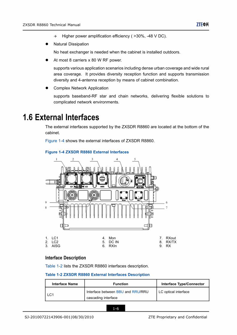
1.6 External InterfacesThe external interfaces supported by the ZXSDR R8860 are located at the bottom of thecabinet.
Figure 1-4 shows the external interfaces of ZXSDR R8860.
Figure 1-4 ZXSDR R8860 External Interfaces
1. LC12. LC23. AISG
4. Mon5. DC IN6. RXIn
7. RXout8. RX/TX9. RX
Interface DescriptionTable 1-2 lists the ZXSDR R8860 interfaces description.
Table 1-2 ZXSDR R8860 External Interfaces Description
Interface Name Function Interface Type/Connector
LC1Interface between BBU and RRU/RRU
cascading interface
LC optical interface
1-6
SJ-20100722143906-001|08/30/2010 ZTE Proprietary and Confidential

Chapter 1 Product Overview
Interface Name Function Interface Type/Connector
LC2Interface between BBU and RRU/RRU
cascading interface
LC optical interface
AISG AISG device interface 8-core aerial socket
Mon External device interface 37-core aerial socket
DC INPower interface DC interface connector: 4-pin
straight round connector
RXIn Frequency expansion interface N connector
RXout Frequency expansion interface N connector
RX/TXReceive/Transmit main set RF cable
interface
50 Ω DIN connector
RX Receive diversity RF cable interface 50 Ω DIN connector
1.7 Application ScenariosZXSDR R8860 supports gantry-mount, wall-mount, pole-mount and simplified—cabinetintegrative installation modes.
The application scenarios are classified into the following situations according to differentinstallation conditions, power supply requirements and user demands:
l In the condition of ZXSDR R8860 indoor installation with the DC power cable 10m outside the equipment room and without Level B and above lightning moduleconfigured in the indoor power output, the indoor DC lightning box is adopted forpower supply and power distribution.
l When ZXSDR R8860 is installed outdoors, an external DC lightning box is adoptedfor power supply and power distribution.
l Awave trap module is needed in some countries or districts due to the special demandon the radio network or stations.
Wall-Mount Installation
Figure 1-5 illustrates the wall-mount installation
1-7
SJ-20100722143906-001|08/30/2010 ZTE Proprietary and Confidential

ZXSDR R8860 Technical Manual
Figure 1-5 ZXSDR R8860 Wall-Mount Mode
Pole-Mount Installation
This section illustrates the ZXSDR R8860 pole-mount installation in terms of double andthree cabinets installation.
l Two ZXSDR R8860 cabinets
Figure 1-6 illustrates two ZXSDR R8860 cabinets mounted on a pole.
1-8
SJ-20100722143906-001|08/30/2010 ZTE Proprietary and Confidential

Chapter 1 Product Overview
Figure 1-6 Two ZXSDR R8860 Cabinets Pole-Mount Mode
l Three ZXSDR R8860 cabinets
Figure 1-7 illustrates three ZXSDR R8860 cabinets mounted on a pole.
Figure 1-7 Three ZXSDR R8860 Cabinets Pole-Mount Mode
1-9
SJ-20100722143906-001|08/30/2010 ZTE Proprietary and Confidential

ZXSDR R8860 Technical Manual
1.8 Work Principle
1.8.1 System StructureThe ZXSDR R8860 system structure includes a DC Power (Power source module), FL(Filter LNA module), TR (Transceiver module,) and PA (Power Amplifier module). It hasfollowing two reserved ports:
l The ZXSDR R8860 provides an external port (Rx out) to support the mutual mainset/diversity combination mode. The FL main set reception Low Noise Amplifier (LNA)output port delivers the power division function.
l An electronic switch is set at the receive diversity channel and an external input portis reserved to deliver the compatibility with the long-distance frequency. The systemcan switch over to input signals through the FL of local Radio Unit (RU) or throughanother Remote Radio Unit (RRU).
Figure 1-8 shows the overall system structure.
Figure 1-8 ZXSDR R8860 System Structure
1.8.2 Signal FlowThe ZXSDR R8860 signal flow is described below.
Forward FlowThe forward signal flow consists of following.
1-10
SJ-20100722143906-001|08/30/2010 ZTE Proprietary and Confidential
Chapter 1 Product Overview
1. After receiving the data modulated by the baseband unit through the Common PublicRadio Interface (CPRI) interface, the up conversion is done by the TR and then thesignal is sent to Power Amplifier (PA).
2. The PA amplifies the power of signals and then sends it to the (Duplex Filter) DFL.3. The FL duplexes and filters the RF signals and then transmits it through the antenna.
Reverse Flow
The reverse signal flow consists of the following.
1. The FL filters the backward CDMA signals from the antenna, amplifies the power ofthese signals before sending them to the TR.
2. The TR performs down conversion and converts the signal into baseband digitalsignals and then transmits to the baseband unit through the CPRI interface.
1.9 Networking
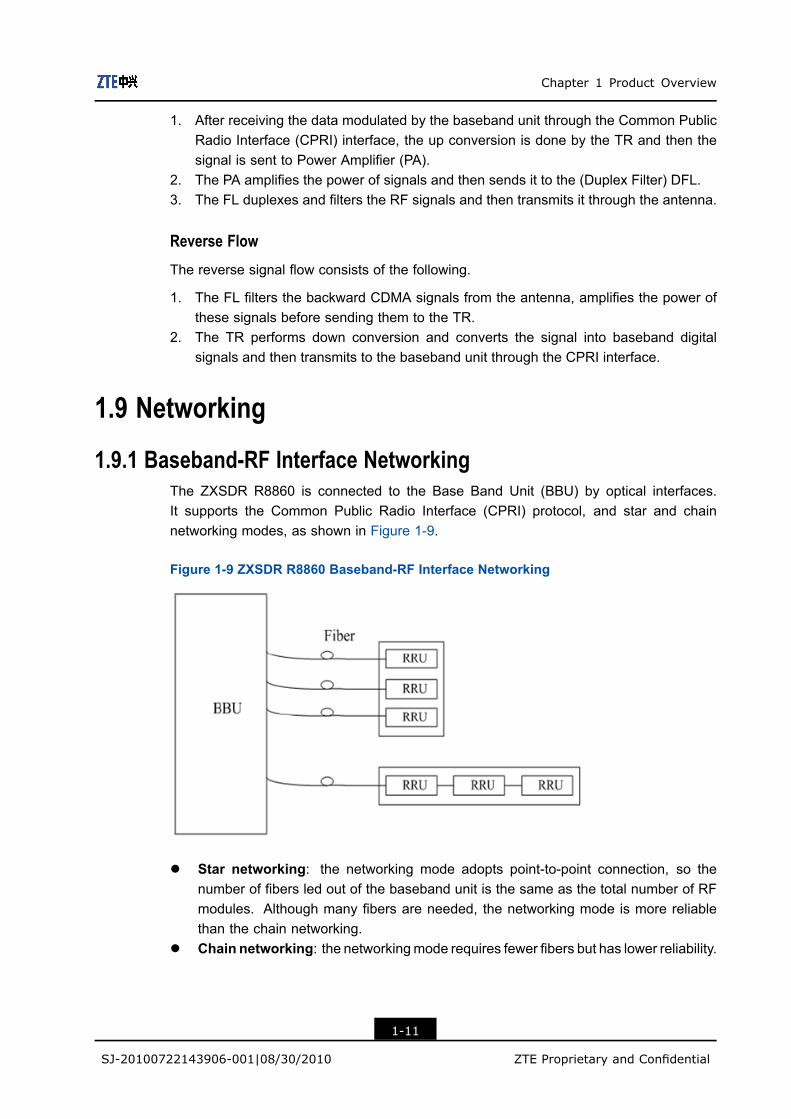
1.9.1 Baseband-RF Interface NetworkingThe ZXSDR R8860 is connected to the Base Band Unit (BBU) by optical interfaces.It supports the Common Public Radio Interface (CPRI) protocol, and star and chainnetworking modes, as shown in Figure 1-9.
Figure 1-9 ZXSDR R8860 Baseband-RF Interface Networking
l Star networking: the networking mode adopts point-to-point connection, so thenumber of fibers led out of the baseband unit is the same as the total number of RFmodules. Although many fibers are needed, the networking mode is more reliablethan the chain networking.
l Chain networking: the networkingmode requires fewer fibers but has lower reliability.
1-11
SJ-20100722143906-001|08/30/2010 ZTE Proprietary and Confidential

ZXSDR R8860 Technical Manual
1.9.2 Cascade NetworkingIn the case where RRUs are close to each other but are far away from BBU, the cascadenetworking through CPRI interface is recommended to save optical fibers.
Alternatively, a cascade networking is also type of chain networking.
Figure 1-10 shows the cascade networking through CPRI interface.
Figure 1-10 ZXSDR R8860 Cascade Networking
RRUs are connected by optical fiber. The RRU optical interface LC1 serves to connectBBU or the upper level RRU while LC2 serves to connect the lower level RRU.
1.9.3 Frequency Extension NetworkingZXSDR R8860 supports mutual receive diversity by means of cabinet combination so thatit can support high-carrier or great-carrier-frequency-difference application.
Figure 1-11 shows the frequency extension networkingmode supported by ZXSDRR8860.
1-12
SJ-20100722143906-001|08/30/2010 ZTE Proprietary and Confidential

Chapter 1 Product Overview
Figure 1-11 ZXSDR R8860 Frequency Extension Networking
1.10 Equipment Management Modes
1.10.1 OMC ModeThe NetNumen™M3 network management system (NMS) developed by ZTE can be usedto operate and maintain the ZXSDR R8860, as shown in Figure 1-12
1-13
SJ-20100722143906-001|08/30/2010 ZTE Proprietary and Confidential

ZXSDR R8860 Technical Manual
Figure 1-12 ZXSDR R8860 Operation and Maintenance –OMC Mode
The Network Element (NE) communicates with the NMS through the TCP/IP protocol.
The NetNumen™ M3 provides the following functions:l Configuration Managementl Performance Managementl Fault Managementl Security Managementl Report Managementl System Tools
1.10.2 LMT ModeA Local Maintenance Terminal (LMT) can be used to operate and maintain the ZXSDRR8860, as shown in Figure 1-13.
1-14
SJ-20100722143906-001|08/30/2010 ZTE Proprietary and Confidential

Chapter 1 Product Overview
Figure 1-13 ZXSDR R8860 Operation and Maintenance System (LMT Mode)
Implementation of power query, power increase/decrease or scaling of ZXSDR R8860 canbe performed through the LMT.
1.11 Technical Indices
1.11.1 Engineering IndicesTable 1-3 describes the engineering indices of ZXSDR R8860.
Table 1-3 ZXSDR R8860 Engineering Indices
Item Indices
Overall Dimension Width x Height x Depth: 320mm x 500mm x 172mm
Upper Enclosure Dimension Width x Height x Depth: 320mm x 370mm x 72mm
Lower Enclosure Dimension Width x Height x Depth: 320mm x 500mm x 100mm
Weight < 22 kg
Power -48V DC; -40V~-57 V
Work Temperature -40 ℃ to 55 ℃-40 ℉ to 131 ℉
Work Humidity 5% RH ~ 95% RH
1-15
SJ-20100722143906-001|08/30/2010 ZTE Proprietary and Confidential

ZXSDR R8860 Technical Manual
Item Indices
Power Consumption of Normal Work
Under -48V DC Power Supply
l 1 Carrier
à Output Power: 20W/C/S
à Power Consumption: 160 W
l 2 Carrier
à Output Power: 20W/C/S
à Power Consumption: 200 W
l 3 Carrier
à Output Power: 20W/C/S
à Power Consumption: 250 W
The technical indices of the indoor DC lightning box, exemplified byJD40K085C20H2–K1Z, are listed in Table 1-4, which is subject to the actual fieldtechnical specifications for practical application.
Table 1-4 JD40K085C20H2–K1Z DC Lightning Box Technical Indices
Item Index
Dimensions Width x Height x Depth: 400 mm x 450 mm x 100 mm (The
height of top cover box lock excluded)
Nominal Working Voltage –48V
Installation Mode Indoor wall-mount installation
Working Temperature -5 ℃ to 70 ℃
Working Humidity ≤ 95% RH
1.11.2 Performance IndicesTable 1-5 lists the performance indices of the ZXSDR R8860.
Table 1-5 ZXSDR R8860 Performance Indices
Name Index Value
Interface protocol CPRI
RRU level number supported by a single fiber 4
Baseband— RF
interface
Single link length supported by RRU < 80 Km
Dry contact 4 Booleans: 4 inputsEnvironment
monitoring
interfaceSerial port One RS485
Capacity of a single cabinet 8C1S
1-16
SJ-20100722143906-001|08/30/2010 ZTE Proprietary and Confidential

Chapter 1 Product Overview
Name Index Value
Mean time between failures (MTBF) > 100,000 hours
1.11.3 RF IndiciesRF indices of ZXSDR R8860 comply with 3GPP2 C.S0010-C, Recommended MinimumPerformance Standards for cdma2000 Spread Spectrum Base Station and 3GPP2C.S0032-A, Recommended Minimum Performance Standards for CDMA2000 High RatePacket Data Access Network.
Table 1-6 lists the RF indices of the ZXSDR R8860.
Table 1-6 ZXSDR R8860 RF Indices
Name Index Value
Operating Band Class 800 MHz (Band Class 0), compliant with 3GPP2 C.S0010-C
Standards.
1900MHz PCS band with its uplink as 1850MHz ~ 1915
MHz and downlink as 1930MHz ~ 1995Mhz
AWS band with its uplink as 1710 MHz ~ 1755MHz and
downlink as 2110 MHz ~ 2155MHz
450MHz (Band Class 5) with its uplink as 450 MHz ~
460MHz and downlink as 460 MHz ~ 470MHz
850MHz (Band Class 10) with its uplink as 806 MHz ~
821MHz and downlink as 851 MHz ~ 866MHz
420MHz (Band Class 5) with its uplink as 410 MHz ~
420MHz and downlink as 420 MHz ~ 430MHz
2100MHz (Band Class 6) with its uplink as 1920 MHz ~
1979.95MHz and downlink as 2110 MHz ~ 2169.95MHz
Mode Index Name Index Value
Transmitter output
frequency tolerance
± 0.05ppm
Occupied bandwidth of
channel output spectrum
1.23MHz/carrier (800MHz)
1.25MHz/carrier (450MHz/1900MHz/AWS/850MHZ/2100
MHz)
Transmit power at the
antenna port
60W/80W
Transmit power stability The total transmit power is within +2dB and -4dB of the
rated power.
Transmitter
Indices
1-17
SJ-20100722143906-001|08/30/2010 ZTE Proprietary and Confidential

ZXSDR R8860 Technical Manual
Name Index Value
Transmitter
intermodulation
performance
The BTS transmits at the rated power but the output
power of another BTS is 30 dB less than the rated
power of the former BTS. When the powers of the two
BTSs are combined at the antenna port, the generated
intermodulation spurious emission meets the conducted
spurious emission requirement. The intermediate frequency
difference of transmit signals of the two BTSs is 1.25 MHz,
which meets 3GPP2 C.S0010-C technical standard.
Standing wave ratio of
the RFE (transmitter)
< 1.50
Receiver sensitivity <-128dBm(RC1)
Receiver dynamic range -128dBm ~ -65dBm
Noise figure < 3
Conducted and radiated
spurious emissions
l -80dBm measured within the BTS receive band;
l -60 dBm measured within the BTS transmit band;
l -47 dBm measured within other bands with RBW = 30
kHz, meeting 3GPP2 C.S0010-C standards.
Receiver
Indices
Standing wave ratio of
the RFE (receiver)
< 1.50
1.12 Compliance StandardsZXSDR R8860 follows the following compliance standards.
l ANSI J-STD-008, Personal Station-Base Station Compatibility Requirement for 1.8 to2.0 GHz Code Division Multiple Access (CDMA) Personal Communications System,1996.
l 3GPP2 C.S0001-A version 5.0: Introduction to CDMA2000 Standards for SpreadSpectrum Systems - Release A.
l 3GPP2 C.S0002-A version 6.0 (TIA/EIA IS-2000.2-A-2): Physical Layer Standard forCDMA2000 Spread Spectrum Systems - Release A.
l 3GPP2 C.S0003-A version 6.0 (TIA/EIA IS-2000.3-A-2): Medium Access Control(MAC) Standard for CDMA2000 Spread Spectrum Systems - Release A, Addendum2.
l 3GPP2 C.S0004-A version 6.0 (TIA/EIA IS-2000.4-A-2): Signaling Link AccessControl (LAC) Specification for CDMA2000 Spread Spectrum Systems - Release A.
l 3GPP2 C.S0005-A version 6.0 (TIA/EIA IS-2000.5-A-2): Upper Layer (Layer3) Signaling Standard for CDMA2000 Spread Spectrum Systems - Release A,Addendum 2.
l TIA/EIA/TSB-58, Administration Parameter Value Assignments for TIA/EIA WidebandSpread Spectrum Standards, 1995.
1-18
SJ-20100722143906-001|08/30/2010 ZTE Proprietary and Confidential

Chapter 1 Product Overview
l TIA/EIA/TSB-74, Support for 14.4 Kbps Data Rate and PCS Interaction for WidebandSpread Spectrum Cellular System, 1995.
l TIA/EIA/IS-95-A, Mobile Station-Base Station Compatibility Standard for Dual-ModeWideband Spread Spectrum Cellular Systems.
l TIA/EIA/IS-95, Mobile Station-Base Station Compatibility Standard for Dual-ModeWideband Spread Spectrum Cellular Systems.
l TIA/EIA/IS-637, Short Message Services for Wideband Spread Spectrum CellularSystems, 1997.
l TIA/EIA/IS-127, Enhanced Variable Rate Codec Speech Service Option 3 forWideband Spread Spectrum Digital Systems, 1996.
l TIA/EIA/IS-634A, MSC-BS Interface for Public Communications Networks, 1998.l TIA/EIA/IS-658, Data Service Interworking Function Interface for Wideband Spread
Spectrum Systems.l CDG RF36, Markov Service Option for Wideband Spread Spectrum Communications
Systems.l TIA/EIA/IS-725, Over-the-Air Service Provisioning of Mobile Stations in Wideband
Spread Spectrum Systems, 1997l TIA/EIA/IS-728, Inter-System Link Protocol.l TIA/EIA/IS-733, High Rate Speech Service Option 17 for Wideband Spread Spectrum
Communication Systems.l TIA/EIA/IS-707, Data Service Options for Wideband Spread Spectrum Systems,
1998.l TIA/EIA/IS-707-A-2 Data Service Options for Spread Spectrum Systems Addendum
2, 2000.l ITU-T Q.714 Signaling connection control part (SCCP).l ITU-T Q.704 Signal link (MTP3).l ITU-T Q.703 Signal link (MTP2).l 3GPP2 C.S0024-A (TIA/EIA IS-856-A): CDMA2000 High Rate Packet Data Air
Interface Specification, August 2005.l 3GPP2 C.S0024 (TIA/EIA IS-856): CDMA2000 High Rate Packet Data Air Interface
Specification, October 2002.l 3GPP2 A.S0008 (TIA/EIA IS-878), IOS Specification for High Rate Packet Data
(HRPD) Radio Access Network Interfaces.l 3GPP2 A.S0008-A. Interoperability Specification (IOS) for High Rate Packet Data
(HRPD) Radio Access Network InterfacesWith Session Control in the Access Networkl 3GPP2 A.S0007, Inter-Operability Specification (IOS) for High Rate Packet Data
(HRPD) Access Network Interfaces, November 2001.l 3GPP2 C.S0029: Test Application Specification (TAS) for High Rate Packet Data Air
Interface.l l 3GPP2 C.S0032-A, Recommended Minimum Performance Standards for
CDMA2000 High Rate Packet Data Access Network, December 2005.l 3GPP2 C.S0032, Recommended Minimum Performance Standards for CDMA2000
High Rate Packet Data Access Network, January 2004.l 3GPP2 C.S0010-A (TIA-97-D), Recommended Minimum Performance Standards for
cdma2000 Spread Spectrum Base Stations, March 2001.
1-19
SJ-20100722143906-001|08/30/2010 ZTE Proprietary and Confidential

ZXSDR R8860 Technical Manual
l 3GPP2 C.S0054-A, cdma2000 High Rate Broadcast-Multicast Packet Data AirInterface Specification.
l 3GPP2 C.S0054, cdma2000 High Rate Broadcast-Multicast Packet Data Air InterfaceSpecification.
l ASIG1:Issue 1.1, Control interface for antenna line devicesl QB/CU 001-99, 800MHz CDMA Digital Cellular Mobile Network Specifications (Trial),
China Unicom, 1999.l QB/CU 003-99, Technical Specifications for China Unicom 800MHz CDMA Digital
Cellular Mobile System Equipment: Base Station (Trial), China Unicom, 1999l QB/CU 006-99, Technical Specifications for Interfaces between Switches and Base
Stations in China Unicom 800MHz CDMA Digital Cellular Mobile Network (Trial),China Unicom, 1999
l QB/CU 007-99, China Unicom 800MHz CDMA Digital Cellular Mobile Network AirInterface Specification (Trial), China Unicom, 1999
1-20
SJ-20100722143906-001|08/30/2010 ZTE Proprietary and Confidential
Chapter 2Hardware DescriptionsTable of Contents
Cabinet ......................................................................................................................2-1Modules .....................................................................................................................2-3External Cables..........................................................................................................2-5Main Antenna Feeder System ..................................................................................2-10
2.1 Cabinet
2.1.1 External StructureThe ZXSDR R8860 cabinet is fully sealed. The top and bottom enclosures are unitedby an anti-theft screw with two hinges as stop blocks. The top enclosure is equippedwith a handle to facilitate conveyance and installation. A reserved engineering installationposition on the bottom enclosure makes it easy to install the cabinet under various workingenvironments by using installation accessories.
Figure 2-1 shows the ZXSDR R8860 cabinet external structure.
2-1
SJ-20100722143906-001|08/30/2010 ZTE Proprietary and Confidential

ZXSDR R8860 Technical Manual
Figure 2-1 Cabinet Outer Structure
1. Bottom Enclosure 2. Hinge 3. Top Enclosure
Enclosure Dimension DescriptionTable 2-1 lists the dimensions of top and bottom enclosures.
Table 2-1 ZXSDR R8860 Cabinet Enclosure Dimensions
Enclosure Dimension (W x H x D)
Top 320mm × 370mm × 72mm
Bottom 320mm × 500mm × 100mm
2.1.2 Indoor StructureTheZXSDR R8860 cabinet consists of four modules such as FL module, PA module, DCPower module, and TR module.
Figure 2-2 shows the ZXSDR R8860 cabinet internal structure.
2-2
SJ-20100722143906-001|08/30/2010 ZTE Proprietary and Confidential

Chapter 2 Hardware Descriptions
Figure 2-2 ZXSDR R8860 Cabinet Internal Structure
1. TR Module2. DC Power Module
3. PA Module4. FL Module
2.1.3 Ventilation and Heat-dissipation PrinciplesThe ZXSDRR8860 cabinet is naturally cooled through air cooled fins on the top and bottomenclosures. Natural heat dissipation replaces heat exchanger requirement for outdoorapplication. In addition, a heat sink is equipped at the bottom of the cabinet to enhanceheat dissipation.
2.2 Modules
2.2.1 Modules ListThe ZXSDR R8860 cabinet consists of four modules such as:l FL modulel PA modulel DC Power modulel TR module
2.2.2 Filter LNA (FL)The functions of the Filter LNA (FL) module are as follows.
l Performs filtering and low noise amplification of the reverse CDMA signal from theantenna.
2-3
SJ-20100722143906-001|08/30/2010 ZTE Proprietary and Confidential

ZXSDR R8860 Technical Manual
l Filters the forward RF signal to be sent.l Reports LNA alarms to the TR.l In the case of main/diversity combined cabinets, the main receive LNA output end of
the FL has the power splitter function and reserves an external port (RXout).
2.2.3 Transceiver (TR)The Transceiver (TR) is the main control module of ZXSDR R8860. It performscommunication, control, alarm, and version management for ZXSDR R8860.
Following are the functions of the TR module.
l Forward link processing
à Conversion from baseband signal to RF signal
à Conversion of output IQ data format
à Power calibration and detection processing
à Peak clipping/digital pre-distortion processing
à Digital IF processing
à Gain adjustment (calibration)
l Reverse link processing
à Conversion from RF signal to baseband signal
à Digital IF processing
à RSSI and RAB report
à In-band anti-interference function
à Spectrum report
à Automatic gain control (AGC)
à Output IQ data format conversion
à Supports switching between different receive channel signals in the case ofmain/diversity combined cabinets
l Clock processing
Performs clock recovery for data on the CPRI between the ZXSDR R8860 and theBBU generating a reference clock source and performs phase lock for the referenceclock by utilizing a local high-stability clock. The working clocks generated includethe master clock, frame- frequency clock, digital processing clock, and RF basebandclock.
l Monitoring
à PA forward power detection function: when the temperature threshold isexceeded, the TR reports the relevant alarm and controls the PA through the PAoutput enable/disable signal.
2-4
SJ-20100722143906-001|08/30/2010 ZTE Proprietary and Confidential

Chapter 2 Hardware Descriptions
à PA reversed power (standing wave ratio) detection function: when thetemperature threshold standing of the wave radio is exceeded, the TR reportsthe relevant alarm and controls the PA through the PA output enable/disablesignal.
à PA temperature detection function: When the temperature threshold is exceeded,the TR reports the relevant alarm and controls the PA through the PA outputenable/disable signal.
à PA output enable/disable
à TR transmit output power detection
à FL two-channel LNA alarm detection and report
à DC Power input undervoltage/overvoltage alarm detection and report
à DC Power output undervoltage/overvoltage alarm detection and report
à DC Power output overcurrent alarm detection and report
à System environment monitoring
à CPRI self-test alarm
à Key chip self-test alarm
2.2.4 Power Amplifier (PA)The Power Amplifier (PA) module performs the following functions:
l Amplifies downlink RF signal input via the TR and then sends the signal to the FL.l Provides digital pre-distortion feedback signals for the TR.l Provides a PA output enable/disable interface.
2.2.5 PowerThe DC Power module converts -48V DC input power supply to DC power supply requiredby the PA, TR, or FL modules.
2.3 External Cables
2.3.1 DC Power CableThe 4-core cable is used as DC power cable in ZXSDR R8860 . It is made according tothe on-site survey requirement.
One end of the cable is soldered with a straight round connector while the other end isbare, with a label indicating signal definition.
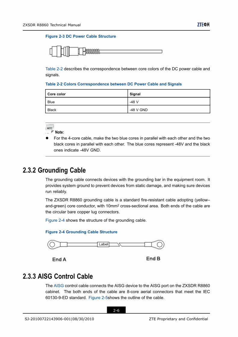
Figure 2-3 shows the structure of the DC power cable.
2-5
SJ-20100722143906-001|08/30/2010 ZTE Proprietary and Confidential
ZXSDR R8860 Technical Manual
Figure 2-3 DC Power Cable Structure
Table 2-2 describes the correspondence between core colors of the DC power cable andsignals.
Table 2-2 Colors Correspondence between DC Power Cable and Signals
Core color Signal
Blue -48 V
Black -48 V GND
Note:l For the 4-core cable, make the two blue cores in parallel with each other and the two
black cores in parallel with each other. The blue cores represent -48V and the blackones indicate -48V GND.
2.3.2 Grounding CableThe grounding cable connects devices with the grounding bar in the equipment room. Itprovides system ground to prevent devices from static damage, and making sure devicesrun reliably.
The ZXSDR R8860 grounding cable is a standard fire-resistant cable adopting (yellow–and-green) core conductor, with 10mm2 cross-sectional area. Both ends of the cable arethe circular bare copper lug connectors.
Figure 2-4 shows the structure of the grounding cable.
Figure 2-4 Grounding Cable Structure
2.3.3 AISG Control CableThe AISG control cable connects the AISG device to the AISG port on the ZXSDR R8860cabinet. The both ends of the cable are 8-core aerial connectors that meet the IEC60130-9-ED standard. Figure 2-5shows the outline of the cable.
2-6
SJ-20100722143906-001|08/30/2010 ZTE Proprietary and Confidential

Chapter 2 Hardware Descriptions
Figure 2-5 Outline of the AISG control cable
2.3.4 Optical Fiber CableThere are two types of optical fibers used, one is used to connect with BBU while other isused to connect cascaded cabinets. The ZXSDR R8860 adopts single mode 2-core fibertail and multi mode fiber. The tail length depends on the actual situation.
Figure 2-6 shows the structure of the fiber tail used to connect BBU.
Figure 2-6 Fiber Cable Used to Connect BBU.
1. DLC optical connector2. Outdoor fiber sealing nut
component
3. Label4. Single mode 2-core fiber
tail
5. LC optical connector
Note:
The fiber is used in outdoor environments. The fiber sheath should be waterproof andanti-ultraviolet. The working temperature should be in the range of -40℃~+80℃. Thesheath is of black color.
Figure 2-7 shows the optical fiber cable used for cascaded cabinets.
Figure 2-7 Fiber Used for Cascaded Cabinets
2.3.5 Environment Monitoring CableThe environment monitoring cable serves as input/output dry contacts and is used totransmit RS485 monitoring signals. Figure 2-8 shows the outline of the cable.
2-7
SJ-20100722143906-001|08/30/2010 ZTE Proprietary and Confidential

ZXSDR R8860 Technical Manual
Figure 2-8 Environment Monitoring Cable
One end of the environment monitoring cable that joins the ZXSDR R8860 is 37-coreaerial connector, which meets the GJB599 III standard. Figure 2-9shows the outline of theconnector.
Figure 2-9 Outline of Connector
Table 2-3 describes the connector pins and connecting cores.
Table 2-3 Environment Monitoring Cable Pins and Connecting Cores Description
Pin Core color Signal description
15/16 White and blue/blue Dry contact 4 -/+
17/18 White and orange/orange Dry contact 3 -/+
19/20 White and green/green Dry contact 2 -/+
21/22 White and brown/brown Dry contact 1 -/+
23/24 Red and blue/blue RS485 received
25/26 Red and orange/orange RS485 transmission
2.3.6 Carrier Sector Extension CableThe carrier sector extension cable is used to connect two ZXSDR R8860 cabinets toincrease the number of carrier sectors. Figure 2-10 shows the structure of the carriersector extension cable. End A and End B are N type male connectors.
2-8
SJ-20100722143906-001|08/30/2010 ZTE Proprietary and Confidential

Chapter 2 Hardware Descriptions
Figure 2-10 Carrier Sector Extension Cable
2.3.7 RF Jumper CableRF jumper cable is used to transfer signals between ZXSDR R8860cabinet and antenna,between ZXSDR R8860cabinet and main feeder cable, and between main feeder cableand antenna.
When the distance between antenna and ZXSDR R8860cabinet is less and the adoptedfeeder cable is of 1/2 in. then, the jumper cable is not used, rather ZXSDR R8860cabinetis directly connected with the feeder cable and feeder cable is connected to the antenna.If the adopted feeder cable is of 7/8 in. or 5/4 in. then jumper is used.Figure 2-11 showsthe RF jumper cable.
Figure 2-11 RF Jumper Cable
Note:
The length of the RF jumper cable is determined according to the actual situation.
2-9
SJ-20100722143906-001|08/30/2010 ZTE Proprietary and Confidential

ZXSDR R8860 Technical Manual
2.4 Main Antenna Feeder System
2.4.1 Main Antenna Feeder System StructureThe typical configurations of ZXSDR R8860 main antenna feeder system described belowincludes:l ZXSDR R8860 configured with common antennal ZXSDR R8860 configured with common antenna and AISG dual tower amplifierl ZXSDR R8860 configured with electrically tuned antenna (1)l ZXSDR R8860 configured with electrically tuned antenna (2)l ZXSDR R8860 configured with electrically tuned antenna, AISG dual tower amplifier
ZXSDR R8860 configured with common antenna
In this configuration, generally ZXSDR R8860 installation position is near antenna andthey are all installed on the building top. ZXSDR R8860 is connected to the antenna by1/2″feeder directly, occasionally 5/4″or 7/8″feeder is adopted, as shown in Figure 2-12.
Figure 2-12 ZXSDR R8860 Configured with Common Antenna
ZXSDR R8860 configured with common antenna and AISG dual tower amplifier
In this configuration, generally ZXSDR R8860 is installed on the tower. ZXSDR R8860 isconnected to the antenna by 5/4″or 7/8″feeder, as shown in Figure 2-13.
2-10
SJ-20100722143906-001|08/30/2010 ZTE Proprietary and Confidential

Chapter 2 Hardware Descriptions
Figure 2-13 ZXSDR R8860 Configured with Common Antenna, AISG Dual TowerAmplifier
ZXSDR R8860 configured with electrically tuned antenna (1)
In this configuration, generally ZXSDR R8860 installed near the antenna on the buildingtop. ZXSDR R8860 is connected to the antenna by 1/2″feeder directly, occasionally 5/4″or7/8″feeder is adopted, as shown in Figure 2-14.
2-11
SJ-20100722143906-001|08/30/2010 ZTE Proprietary and Confidential

ZXSDR R8860 Technical Manual
Figure 2-14 ZXSDR R8860 Configured with Electrically Tuned Antenna (1)
ZXSDR R8860 configured with electrically tuned antenna (2)
In this configuration, generally ZXSDR R8860is installed near the top of the tower. ZXSDRR8860 is connected to the antenna by 5/4″or 7/8″feeder is adopted, as shown in Figure2-15.
2-12
SJ-20100722143906-001|08/30/2010 ZTE Proprietary and Confidential

Chapter 2 Hardware Descriptions
Figure 2-15 ZXSDR R8860 Configured with Electrically Tuned Antenna (2)
ZXSDR R8860 configured with electrically tuned antenna, AISG dual tower amplifier
In this configuration, generally ZXSDR R8860is installed near the top of the tower. ZXSDRR8860 is connected to the antenna by 5/4″or 7/8″feeder is adopted, as shown in Figure2-16.
2-13
SJ-20100722143906-001|08/30/2010 ZTE Proprietary and Confidential

ZXSDR R8860 Technical Manual
Figure 2-16 ZXSDR R8860 Configured with Electrically Tuned Antenna and AISG DualTower Amplifier
2.4.2 AntennaThe ZXSDR R8860 antenna feeder system adopts common antenna or electrical antenna.For the electrical antenna, you can adjust the lever to control the embedded adjuster andthus to tune the downtilt angle of the antenna. The tilt reflects the direction from which the
2-14
SJ-20100722143906-001|08/30/2010 ZTE Proprietary and Confidential

Chapter 2 Hardware Descriptions
antenna receives the strongest signals. The tilt of the uni-directional antenna can be tunedmechanically, and electrical tilt is used to tune the omni-directional antenna.
The principle of the electrical tilt is as follows:
The adjustment of the phase of the antenna array vibrator changes the maximum verticaland horizontal components and alters synthesized field strength, thus making the verticalpattern of the antenna declining. Because the antenna field strength increases ordecreases simultaneously in all directions, which ensures that the antenna pattern hardlyvaries with the tilt. This diminishes the coverage of the main lobe and ensures that nointerference occurs when the coverage of the whole pattern decreases in its service area.
2.4.3 Feeder StructureThe feeder is used to receive and transmit radio RF signals between the antenna and theZXSDR R8860. There are many types of feeder cables such as 1/2 inch and 7/8 inchfeeder cable.
When the distance between the ZXSDR R8860 cabinet and antenna is less, then 1/2 inchfeeder cable is used. In this case, the ZXSDR R8860 cabinet is directly connected to the1/2 inch feeder and 1/2 inch feeder cable is connected to antenna.
When the distance between the ZXSDR R8860 cabinet and antenna is more, then 7/8inch feeder cable is used. In this case, ZXSDR R8860 cabinet is first connected to thejumper, then jumper is connected to 7/8 inch feeder cable, and 7/8 inch feeder cable isagain connected to jumper and lastly jumper is connected to antenna.
The antenna may have N type or DIN type interface. The feeder is adapted to female andmale N connectors. Usually both ends of the delivered feeder are male N connector tofacilitate on-site installation.
2-15
SJ-20100722143906-001|08/30/2010 ZTE Proprietary and Confidential

ZXSDR R8860 Technical Manual
This page intentionally left blank.
2-16
SJ-20100722143906-001|08/30/2010 ZTE Proprietary and Confidential

Chapter 3Protocol InterfaceDescriptionTable of Contents
Network Reference Model ..........................................................................................3-1Um Interface ..............................................................................................................3-2Baseband—RF Interface ............................................................................................3-6
3.1 Network Reference ModelFigure 3-1 shows the network reference model of the CDMA2000 1x network.
Figure 3-1 CDMA2000 1x Network Reference Model
The description of the interfaces in Figure 3-1 are described in Table 3-1.
Table 3-1 Interface Description
Interface Description
Abis Interface between BSC and BTS
CPRI Interface between BBU and RRU of the distributed base station
A1/A1p Signaling interface between MSCe/MGW and BSC
A2/A2p Service interface between MSCe/MGW and BSC
3-1
SJ-20100722143906-001|08/30/2010 ZTE Proprietary and Confidential

ZXSDR R8860 Technical Manual
Interface Description
A3 Implements soft handoff between different BSCs (focusing on
the media plane).
A7 Implements soft handoff between different BSCs (focusing on
the control plane).
A8/A8d Implements data transmission between BSS and PCF/PDC.
A9/A9d Implements signaling transmission between BSS and PCF/PDC
A10/A10d Implements data transmission between PCF and PDSN, and
between PDC and PDS.
A11/A11d Implements signaling transmission between PCF and PDSN, and
between PDC and PDS.
3.2 Um InterfaceThe Um interface is the air interface between Mobile Station (MS) and Base TransceiverStation (BTS), complying with the IS-2000 ReleaseA standards and the IS-856-A standard.
CDMA2000 1x Um Interface
The CDMA2000 1x Um interface is composed of physical layer, data link layer anduppermost layer. Figure 3-2 shows the protocol reference model.
Figure 3-2 CDMA2000 1x Um Interface Protocol Reference Model
l The physical layer is a bottom layer, covering various physical channels. It providesbasic radio channels to transmit information of upper layers.
3-2
SJ-20100722143906-001|08/30/2010 ZTE Proprietary and Confidential
Chapter 3 Protocol Interface Description
l The data link layer comprises of Medium Access Control (MAC) sublayer andLink Access Control (LAC) sublayer. The MAC sublayer implements the mappingbetween logical channels and physical channels and delivers the Radio Link Protocol(RLP) function. The LAC sublayer performs authentication, automatic requestretransmission, addressing, segment and reassembly.
l The uppermost layer provides signaling service, voice service, packet data applicationand circuit data application, and implements radio resource, mobility and connectionmanagement of the air interface through signaling service.
CDMA2000 1x EV-DO Um interface
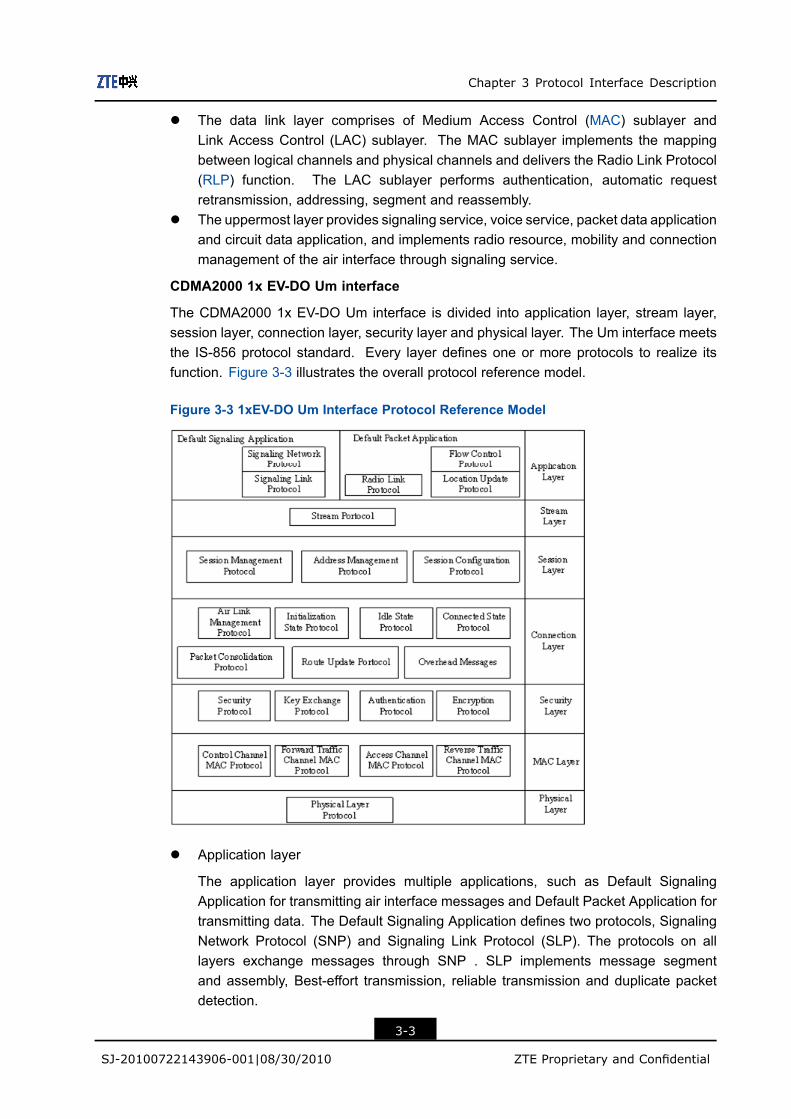
The CDMA2000 1x EV-DO Um interface is divided into application layer, stream layer,session layer, connection layer, security layer and physical layer. The Um interface meetsthe IS-856 protocol standard. Every layer defines one or more protocols to realize itsfunction. Figure 3-3 illustrates the overall protocol reference model.
Figure 3-3 1xEV-DO Um Interface Protocol Reference Model
l Application layer
The application layer provides multiple applications, such as Default SignalingApplication for transmitting air interface messages and Default Packet Application fortransmitting data. The Default Signaling Application defines two protocols, SignalingNetwork Protocol (SNP) and Signaling Link Protocol (SLP). The protocols on alllayers exchange messages through SNP . SLP implements message segmentand assembly, Best-effort transmission, reliable transmission and duplicate packetdetection.
3-3
SJ-20100722143906-001|08/30/2010 ZTE Proprietary and Confidential

ZXSDR R8860 Technical Manual
The Default Packet Application provides a byte stream to transmit packet databetween the terminal and the network. It includes three protocols.
à Flow Control Protocol provides the flow control function for data stream.
à Radio Link Protocol implements byte stream retransmission and duplicate packetdetection, and provides a reliable data link for upper applications.
à Location Update Protocol provides location update program and correspondingmessages for mobility management of packet application.
l Stream layer
The stream layer delivers the following functions:
à It provides the architecture of data packets over the connection application layerby means of data stream authentication.
à It distinguishes priorities signals and user services according to the dataencapsulation protocol of the connection layer.
à It connects users to signal service.
à It allocates independent data stream to applications of different QoSs.
l Session layer
The session layer contains a series of protocols used for session negotiation betweenthe terminal and the network. In the 1xEV-DO system, a session indicates a statejointly maintained between Access Terminal (AT) and Access Network (AN). It includesaddress UATI distributed to the terminal, protocol set determined by the terminal andthe network for air interface communication, protocol configurations in the protocol setand current terminal location. The session layer defines three protocols:
à Session Management Protocol activates other protocols on the layer, ensuressession validity and closes sessions.
à Address Management Protocol manages terminal address (UATI) distribution.
à Session Configuration Protocol (SCP) performs session flow negotiation. In the1xEV-DO system, SCP negotiates the protocol used for communication betweenthe terminal and the network, and how to set protocol parameters.
l Connection layer
The connection layer controls the air link state. In the 1xEV-DO system, an enabledlink between AT and AN means the AT is allocated with RPC, RTC and FTC (FTC isthe time division channel shared by all the subscribers with open connections in thesector).
l Security layer
The security layer delivers the following functions:
à Key exchange. It provides a procedure for the terminal and the network toexchange keys that are used for authentication and encryption.
3-4
SJ-20100722143906-001|08/30/2010 ZTE Proprietary and Confidential

Chapter 3 Protocol Interface Description
à Authentication. It provides a procedure for the terminal and the network toauthenticate over-the-air services.
à Encryption. It provides a procedure for the terminal and the network to encryptover-the-air services.
The security layer covers four protocols, among which Key Exchange Protocol,Authentication Protocol and Encryption Protocol define the three functions mentionedabove respectively while Security Protocol provides public variables for AuthenticationProtocol and Encryption Protocol.
l MAC layer
The MAC layer defines the rules for managing control channel, access channel,forward traffic channel and reverse traffic channel. It contains four protocols, asdescribed below:
à Control Channel MAC Protocol constructs Control channel MAC layer packetfrom one or more Security layer packets, controls packet scheduling andtransmission rule of channels and regulates how the terminal captures thecontrol channel and receives control channel packets.
à Access Channel MAC Protocol defines that the terminal sends timing messagesand power features over the access channel.
à Forward Traffic Channel (FTC) Protocol regulates how to control the rate of theFTC through the DRC and how to support the fixed rate mode and variable ratemode of the FTC.
à Reverse Traffic Channel (RTC) Protocol regulates how the terminal assists thenetwork to capture the RTC and how the terminal and the network choose RFCrate.
l Physical layer
The physical layer defines structure, frequency, power output,modulation/demodulation and coding/decoding of the forward/reverse channel.
BCMCS Um Interface
The Broadcast and Multicast Service (BCMCS) Um interface implements broadcast andmulticast services. Figure 3-4 shows the structure of the BCMCS Um interface protocolstack.
3-5
SJ-20100722143906-001|08/30/2010 ZTE Proprietary and Confidential

ZXSDR R8860 Technical Manual
Figure 3-4 Structure of the BCMCS Um Interface Protocol Stack
l Broadcast Control Protocol processes BCMCS stream registration. The AT sends thestream registration request to the AN so that the AN can broadcasting the streamcontinuously.
l Broadcast Framing Protocol encapsulates, segments and delimits upper layer pack-ets.
l Broadcast Security Protocol provides packet encryption mechanism.l Broadcast MAC Protocol adds forward error correcting codes to form Error Control
Block (ECB) and relays MAC frames to the physical layer. The layer is responsible oflogical channel mapping, constructing and sending broadcast overhead messages.
l Broadcast Physical Protocol provides a logical channel structure.
3.3 Baseband—RF InterfaceThe baseband-RF interface of ZXSDR R8860 complies with the common public radiointerface (CPRI) specification. The CPRI specification was instituted by the CPRI Union,which is an industry cooperation organization devoting itself to institution of internal radiointerface specifications of radio base stations.
The CPRI specification describes the transmission, control and synchronizationmechanisms of user data and control signaling, defining the essential factors such astransmission, connection and control.
From a view of the specification system, the CPRI specification contains the contentsof physical layer and data link layer. It describes characteristics of electrical and opticalinterfaces and multiplexing mechanisms among various data flows in the matter of thephysical layer, and media access control (MAC ), flow control and information flowprotection in the matter of the data link layer.
3-6
SJ-20100722143906-001|08/30/2010 ZTE Proprietary and Confidential
FiguresFigure 1-1 Distributed ZTE BTS Solution .................................................................. 1-1
Figure 1-2 ZXSDR R8860 Position in the Network .................................................... 1-3
Figure 1-3 ZXSDR R8860 Cabinet Appearance ........................................................ 1-3
Figure 1-4 ZXSDR R8860 External Interfaces........................................................... 1-6
Figure 1-5 ZXSDR R8860 Wall-Mount Mode............................................................. 1-8
Figure 1-6 Two ZXSDR R8860 Cabinets Pole-Mount Mode ...................................... 1-9
Figure 1-7 Three ZXSDR R8860 Cabinets Pole-Mount Mode ................................... 1-9
Figure 1-8 ZXSDR R8860 System Structure ........................................................... 1-10
Figure 1-9 ZXSDR R8860 Baseband-RF Interface Networking ............................... 1-11
Figure 1-10 ZXSDR R8860 Cascade Networking.................................................... 1-12
Figure 1-11 ZXSDR R8860 Frequency Extension Networking................................. 1-13
Figure 1-12 ZXSDR R8860 Operation and Maintenance –OMC Mode .................... 1-14
Figure 1-13 ZXSDR R8860 Operation and Maintenance System (LMTMode) ................................................................................................... 1-15
Figure 2-1 Cabinet Outer Structure ........................................................................... 2-2
Figure 2-2 ZXSDR R8860 Cabinet Internal Structure ................................................ 2-3
Figure 2-3 DC Power Cable Structure ...................................................................... 2-6
Figure 2-4 Grounding Cable Structure ...................................................................... 2-6
Figure 2-5 Outline of the AISG control cable ............................................................. 2-7
Figure 2-6 Fiber Cable Used to Connect BBU........................................................... 2-7
Figure 2-7 Fiber Used for Cascaded Cabinets .......................................................... 2-7
Figure 2-8 Environment Monitoring Cable ................................................................. 2-8
Figure 2-9 Outline of Connector ................................................................................ 2-8
Figure 2-10 Carrier Sector Extension Cable.............................................................. 2-9
Figure 2-11 RF Jumper Cable ................................................................................... 2-9
Figure 2-12 ZXSDR R8860 Configured with Common Antenna .............................. 2-10
Figure 2-13 ZXSDR R8860 Configured with Common Antenna, AISG Dual TowerAmplifier ............................................................................................... 2-11
Figure 2-14 ZXSDR R8860 Configured with Electrically Tuned Antenna (1) ............ 2-12
Figure 2-15 ZXSDR R8860 Configured with Electrically Tuned Antenna (2) ............ 2-13
Figure 2-16 ZXSDR R8860 Configured with Electrically Tuned Antenna and AISGDual Tower Amplifier ............................................................................. 2-14
Figure 3-1 CDMA2000 1x Network Reference Model ................................................ 3-1
I

ZXSDR R8860 Technical Manual
Figure 3-2 CDMA2000 1x Um Interface Protocol Reference Model........................... 3-2
Figure 3-3 1xEV-DO Um Interface Protocol Reference Model ................................... 3-3
Figure 3-4 Structure of the BCMCS Um Interface Protocol Stack .............................. 3-6
II

TablesTable 1-1 ZXSDR R8860 Functions .......................................................................... 1-4
Table 1-2 ZXSDR R8860 External Interfaces Description.......................................... 1-6
Table 1-3 ZXSDR R8860 Engineering Indices......................................................... 1-15
Table 1-4 JD40K085C20H2–K1Z DC Lightning Box Technical Indices .................... 1-16
Table 1-5 ZXSDR R8860 Performance Indices ....................................................... 1-16
Table 1-6 ZXSDR R8860 RF Indices....................................................................... 1-17
Table 2-1 ZXSDR R8860 Cabinet Enclosure Dimensions.......................................... 2-2
Table 2-2 Colors Correspondence between DC Power Cable and Signals ................ 2-6
Table 2-3 Environment Monitoring Cable Pins and Connecting CoresDescription............................................................................................... 2-8
Table 3-1 Interface Description.................................................................................. 3-1
III

Tables
This page intentionally left blank.

GlossaryAISG- Antenna Interface Standards Group
AN- Access Network
BBU- BaseBand Unit
BCMCS- Broadcastand Multicast Service
BSC- Base Station Controller
BSS- Base Station System
BTS- Base Transceiver Station
CDMA- Code Division Multiple Access
CPRI- Common Public Radio Interface
DRC- Data Rate Control
FL- Forward Link
FL- Filter LNA
LNA- Low Noise Amplifier
MAC- Medium Access Control
MSCe- Mobile Switching Center emulator
PA- Power Amplifier
PCF- Packet Control Function
V

ZXSDR R8860 Technical Manual
PCF is a board which is responsible for the data selection between multiplereverse traffic channels and data distribution from a forward traffic channel tomultiple cells/sectors during soft handoff.
PDSN- Packet Data Service Node
RAB- Radio Access Bearer
RF- Radio Frequency
RLP- Radio Link Protocol
RRU- Remote Radio Unit
RSSI- Received Signal Strength Indicator
TR- Transceiver
VI