cdma basics
TRANSCRIPT

CDMA
WELCOME TO CDMA OVERVEIW INTRODUCTION TO CDMA RADIO INTERFACE

SECTION 1CODE DIVISION MULTIPLE ACCESS
Section Introduction
•The CDMA frequency band•Frequency Allocation in CDMA•Understanding the DSSS•Codes and their functions in CDMA•Generation of Codes•Spreading And Despreading with Codes

SECTION 2HOW CDMA WORKS
LET US PUT EVERYTHING TOGETHER
Section Introduction
•Forward link Architecture•Reverse Link Architecture•Logical Channels on Forward Link•Logical Channels on Reverse Link

SECTION 3CALL PROCESSING IN CDMA
Section Introduction
•Mobile Initialization•Mobile Registration•Handoff Types•Rake Receiver•Power Control•Vocoding

SECTION 4INTRODUCTION TO DATA IN CDMA
Section Introduction•DATA Layers•Data and Quality•FCH and SCH •Dormant Mode•MAC and RLP•SARA

SECTION 5
INTRODUCTION TO LUCENT BSS
Section Introduction
•Lucent Cellular Network Architecture•Application Processors•OMP-Fx•Modcell Components (3.0& 4.0)


“Hello”
“Shalom” “Guten Tag”
⇔
“Time division”“Frequency division!”
“CHAOS”
“Buenos Dias”“Bonjour”
The SYMPHONY!

GSM Vs CDMA
FREQUENCY REUSE IN CDMA & TDMA
TYPICAL TDMA SYSTEMEACH CELL USES DIFFERENT FREQUENCY
THE PATTERN IS REPEATED FOR THE NEXT SET OF CELL SITES
TYPICAL CDMA SYSTEMEACH CELL USES SAME FREQUENCY
F 1 F 1
F 1
F 1
F 1
F 1
F 1
F 1
F 2
F 5
F 4F 6
F 7 F 3

7 cell re-use pattern
f7
f7
f2
f2
f6
f6
f1
f5f3
f4
f1
f5f3
f4
Frequency Reuse

f1
f1
f1
f1
f1
f1
f1
f1
f1
f1
f1
f1
f1
f1
f1
f1
FREQUENCY REUSE IN in CDMA
f1f1

User 1User 2User 3User 4
User n
Code 1Code 2Code 3Code 4
Code n
1800 MHz 1850 MHz 1910 MHz 1930 MHz 1990 MHz 2000 MHz
Mobile Tx Cell Tx
In GSM small time slots of the spectrum (200 kHz) are used by different users as channels.
Spread spectrum uses much larger slice (1.25 MHz) of the available bandwidth.Same slice is used for all user with no time multiplexing but each user is assigns with a different code to uniquely identify them.
Spread Spectrum Concept

CDMA Cellular Spectrum
846.5MHz
825MHz
824MHz
835MHz
845MHz
849MHz
A’’ A A’B B’ Reverse link
891.5MHz
870MHz
869MHz
880MHz
890MHz
894MHz
A’’ A A’B B’ Forward link
2 - 7
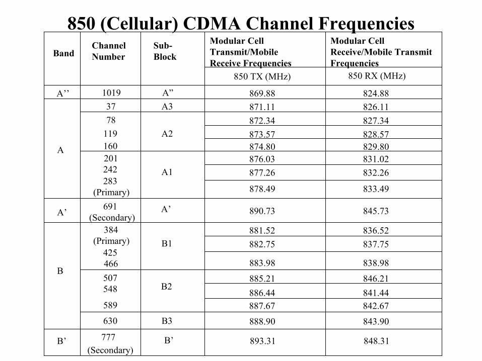
850 (Cellular) CDMA Channel Frequencies
BandChannel Number
Sub-Block
Modular Cell Transmit/Mobile Receive Frequencies
Modular Cell Receive/Mobile Transmit Frequencies
850 TX (MHz) 850 RX (MHz)
A’’ 1019 A” 869.88 824.88
37 A3 871.11 826.11
78 872.34 827.34
119 A2 873.57 828.57160 874.80 829.80201 876.03 831.02242 A1 877.26 832.26283
878.49 833.49(Primary)
A
890.73 845.73691 A’(Secondary)
A’
384 881.52 836.52(Primary) B1 882.75 837.75
425883.98 838.98466
885.21 846.21507B2548
B
589
630
886.44 841.44
887.67 842.67
B3 888.90 843.90
777 B’ 893.31 848.31B’(Secondary)

DIRECT SEQUENCE SPREAD SPECTRUM
A System is said to be using DSSS if it follows the two basic rules mentioned
•The Bandwidth of the Carrier frequency must be much larger than the Bandwidth of the baseband Signals to be transmitted. •The same codes that are used for coding the signal must also be used for decoding the signals.
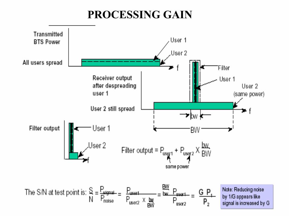
PROCESSING GAIN

The Processing Gain and Capacity Relation
# USERS PROCESING GAIN (dB)
1 21 dB
2 18 dB
3 15 dB
8 12 dB
16 9 dB
32 6 dB
CDMA Spreading GainConsider a user with a 9600
bps Vocoder talking on a CDMA signal 1,228,800 Hz wide.
The processing gain is 1228800/9600=128,
which is 21 db.What happens if additional
users are added?
S/N = G/N
2 Users S/N = ___1___ = 128
3 Users S/N = ___1___ = 64
5 Users S/N = ____1___ = 32
1/128
2/128
4/128
9 Users S/N = ___1___ = 16
17 Users S/N = ____1____ = 8
8/128
16/128
Capacity Quality Related

CDMA’s Nested Spreading Sequences
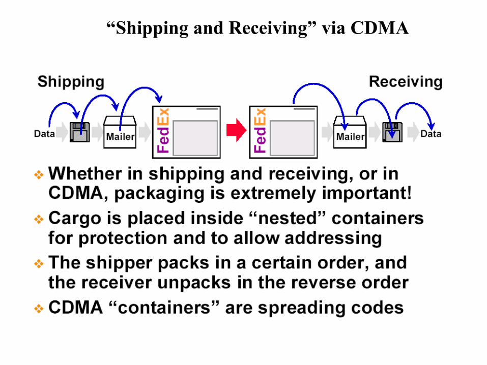
“Shipping and Receiving” via CDMA

U1 = 0110010101001000
C1 ( 100110….10110010)*
=U1C1 ( 100110………………………0000)
U1C1 ( 100110………………………00000)
U1 = 0110010101001000
C1 ( 100110….10110010)*
=
UnCn
U4C4
U3C3
U2C2
UnCn*C1 = 0, UnCn*Cn = Un
U4C4*C1 = 0, U4C4*C4 = U4
U3C3*C1 = 0, U3C3*C3 = U3
U2C2*C1 = 0, U2*C2*C2 = U2
C1*C1 = 1, C2*C2 = 1…. Cn*Cn = 1 BUT C1*C2 = 0…C1*Cn = 0
DSSS Spreading /Despreading

The Three CDMA Spreading Techniques

Orthogonal Sequences
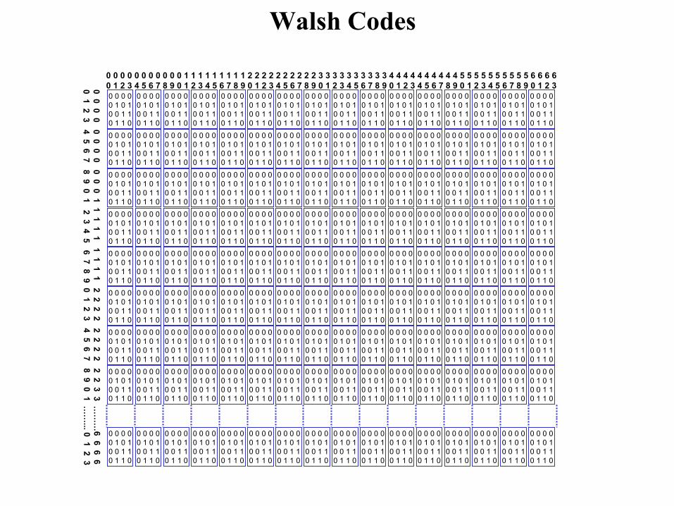
• Definition:Orthogonal functions have zero correlation. Two binary sequences are orthogonal if the process of “XORing” them results in an equal number of 1’s and 0’s. Example:Example:
00000000((XOR) 01010101
------------01010101
• Generation Sequence:Generation Sequence:
- Seed0 0
0 1- Repeat: right & below
- Invert: diagonally
0 0
0 1
0 0
0 1
0 0
0 1
1 1
1 0
0 0 0 00 1 0 10 0 1 10 1 1 0
0 0 0 00 1 0 10 0 1 10 1 1 0
0 0 0 00 1 0 10 0 1 10 1 1 0
0 0 0 00 1 0 10 0 1 10 1 1 0
0 0 0 00 1 0 10 0 1 10 1 1 0
0 0 0 00 1 0 10 0 1 10 1 1 0
0 0 0 00 1 0 10 0 1 10 1 1 0
0 0 0 00 1 0 10 0 1 10 1 1 0
0 0 0 00 1 0 10 0 1 10 1 1 0
0 0 0 00 1 0 10 0 1 10 1 1 0
0 0 0 00 1 0 10 0 1 10 1 1 0
0 0 0 00 1 0 10 0 1 10 1 1 0
0 0 0 00 1 0 10 0 1 10 1 1 0
0 0 0 00 1 0 10 0 1 10 1 1 0
0 0 0 00 1 0 10 0 1 10 1 1 0
0 0 0 00 1 0 10 0 1 10 1 1 0
0 0 0 00 1 0 10 0 1 10 1 1 0
0 0 0 00 1 0 10 0 1 10 1 1 0
0 0 0 00 1 0 10 0 1 10 1 1 0
0 0 0 00 1 0 10 0 1 10 1 1 0
0 0 0 00 1 0 10 0 1 10 1 1 0
0 0 0 00 1 0 10 0 1 10 1 1 0
0 0 0 00 1 0 10 0 1 10 1 1 0
0 0 0 00 1 0 10 0 1 10 1 1 0
0 0 0 00 1 0 10 0 1 10 1 1 0
0 0 0 00 1 0 10 0 1 10 1 1 0
0 0 0 00 1 0 10 0 1 10 1 1 0
0 0 0 00 1 0 10 0 1 10 1 1 0
0 0 0 00 1 0 10 0 1 10 1 1 0
0 0 0 00 1 0 10 0 1 10 1 1 0
0 0 0 00 1 0 10 0 1 10 1 1 0
0 0 0 00 1 0 10 0 1 10 1 1 0
0 0 0 00 1 0 10 0 1 10 1 1 0
0 0 0 00 1 0 10 0 1 10 1 1 0
0 0 0 00 1 0 10 0 1 10 1 1 0
0 0 0 00 1 0 10 0 1 10 1 1 0
0 0 0 00 1 0 10 0 1 10 1 1 0
0 0 0 00 1 0 10 0 1 10 1 1 0
0 0 0 00 1 0 10 0 1 10 1 1 0
0 0 0 00 1 0 10 0 1 10 1 1 0
0 0 0 00 1 0 10 0 1 10 1 1 0
0 0 0 00 1 0 10 0 1 10 1 1 0
0 0 0 00 1 0 10 0 1 10 1 1 0
0 0 0 00 1 0 10 0 1 10 1 1 0
0 0 0 00 1 0 10 0 1 10 1 1 0
0 0 0 00 1 0 10 0 1 10 1 1 0
0 0 0 00 1 0 10 0 1 10 1 1 0
0 0 0 00 1 0 10 0 1 10 1 1 0
0 0 0 00 1 0 10 0 1 10 1 1 0
0 0 0 00 1 0 10 0 1 10 1 1 0
0 0 0 00 1 0 10 0 1 10 1 1 0
0 0 0 00 1 0 10 0 1 10 1 1 0
0 0 0 00 1 0 10 0 1 10 1 1 0
0 0 0 00 1 0 10 0 1 10 1 1 0
0 0 0 00 1 0 10 0 1 10 1 1 0
0 0 0 00 1 0 10 0 1 10 1 1 0
0 0 0 00 1 0 10 0 1 10 1 1 0
0 0 0 00 1 0 10 0 1 10 1 1 0
0 0 0 00 1 0 10 0 1 10 1 1 0
0 0 0 00 1 0 10 0 1 10 1 1 0
0 0 0 00 1 0 10 0 1 10 1 1 0
0 0 0 00 1 0 10 0 1 10 1 1 0
0 0 0 00 1 0 10 0 1 10 1 1 0
0 0 0 00 1 0 10 0 1 10 1 1 0
0 0 0 00 1 0 10 0 1 10 1 1 0
0 0 0 00 1 0 10 0 1 10 1 1 0
0 0 0 00 1 0 10 0 1 10 1 1 0
0 0 0 00 1 0 10 0 1 10 1 1 0
0 0 0 00 1 0 10 0 1 10 1 1 0
0 0 0 00 1 0 10 0 1 10 1 1 0
0 0 0 00 1 0 10 0 1 10 1 1 0
0 0 0 00 1 0 10 0 1 10 1 1 0
0 0 0 00 1 0 10 0 1 10 1 1 0
0 0 0 00 1 0 10 0 1 10 1 1 0
0 0 0 00 1 0 10 0 1 10 1 1 0
0 0 0 00 1 0 10 0 1 10 1 1 0
0 0 0 00 1 0 10 0 1 10 1 1 0
0 0 0 00 1 0 10 0 1 10 1 1 0
0 0 0 00 1 0 10 0 1 10 1 1 0
0 0 0 00 1 0 10 0 1 10 1 1 0
0 0 0 00 1 0 10 0 1 10 1 1 0
0 0 0 00 1 0 10 0 1 10 1 1 0
0 0 0 00 1 0 10 0 1 10 1 1 0
0 0 0 00 1 0 10 0 1 10 1 1 0
0 0 0 00 1 0 10 0 1 10 1 1 0
0 0 0 00 1 0 10 0 1 10 1 1 0
0 0 0 00 1 0 10 0 1 10 1 1 0
0 0 0 00 1 0 10 0 1 10 1 1 0
0 0 0 00 1 0 10 0 1 10 1 1 0
0 0 0 00 1 0 10 0 1 10 1 1 0
0 0 0 00 1 0 10 0 1 10 1 1 0
0 0 0 00 1 0 10 0 1 10 1 1 0
0 0 0 00 1 0 10 0 1 10 1 1 0
0 0 0 00 1 0 10 0 1 10 1 1 0
0 0 0 00 1 0 10 0 1 10 1 1 0
0 0 0 00 1 0 10 0 1 10 1 1 0
0 0 0 00 1 0 10 0 1 10 1 1 0
0 0 0 00 1 0 10 0 1 10 1 1 0
0 0 0 00 1 0 10 0 1 10 1 1 0
0 0 0 00 1 0 10 0 1 10 1 1 0
0 0 0 00 1 0 10 0 1 10 1 1 0
0 0 0 00 1 0 10 0 1 10 1 1 0
0 0 0 00 1 0 10 0 1 10 1 1 0
0 0 0 00 1 0 10 0 1 10 1 1 0
0 0 0 00 1 0 10 0 1 10 1 1 0
0 0 0 00 1 0 10 0 1 10 1 1 0
0 0 0 00 1 0 10 0 1 10 1 1 0
0 0 0 00 1 0 10 0 1 10 1 1 0
0 0 0 00 1 0 10 0 1 10 1 1 0
0 0 0 00 1 0 10 0 1 10 1 1 0
0 0 0 00 1 0 10 0 1 10 1 1 0
0 0 0 00 1 0 10 0 1 10 1 1 0
0 0 0 00 1 0 10 0 1 10 1 1 0
0 0 0 00 1 0 10 0 1 10 1 1 0
0 0 0 00 1 0 10 0 1 10 1 1 0
0 0 0 00 1 0 10 0 1 10 1 1 0
0 0 0 00 1 0 10 0 1 10 1 1 0
0 0 0 00 1 0 10 0 1 10 1 1 0
0 0 0 00 1 0 10 0 1 10 1 1 0
0 0 0 00 1 0 10 0 1 10 1 1 0
0 0 0 00 1 0 10 0 1 10 1 1 0
0 0 0 00 1 0 10 0 1 10 1 1 0
0 0 0 00 1 0 10 0 1 10 1 1 0
0 0 0 00 1 0 10 0 1 10 1 1 0
0 0 0 00 1 0 10 0 1 10 1 1 0
0 0 0 00 1 0 10 0 1 10 1 1 0
0 0 0 00 1 0 10 0 1 10 1 1 0
0 0 0 00 1 0 10 0 1 10 1 1 0
0 0 0 00 1 0 10 0 1 10 1 1 0
0 0 0 00 1 0 10 0 1 10 1 1 0
0 0 0 00 1 0 10 0 1 10 1 1 0
0 0 0 00 1 0 10 0 1 10 1 1 0
0 0 0 00 1 0 10 0 1 10 1 1 0
0 0 0 00 1 0 10 0 1 10 1 1 0
0 0 0 00 1 0 10 0 1 10 1 1 0
0 0 0 00 1 0 10 0 1 10 1 1 0
0 0 0 00 1 0 10 0 1 10 1 1 0
0 0 0 00 1 0 10 0 1 10 1 1 0
0 0 0 00 1 0 10 0 1 10 1 1 0
0 0 0 00 1 0 10 0 1 10 1 1 0
0 0 0 00 1 0 10 0 1 10 1 1 0
0 0 0 00 1 0 10 0 1 10 1 1 0
0 0 0 00 1 0 10 0 1 10 1 1 0
0 0 0 00 1 0 10 0 1 10 1 1 0
0 0 0 0 0 0 0 0 0 0 0 1 1 1 1 1 1 1 1 1 2 2 2 2 2 2 2 2 2 2 3 3 3 3 3 3 3 3 3 3 4 4 4 4 4 4 4 4 4 4 5 5 5 5 5 5 5 5 5 5 6 6 6 60 1 2 3 4 5 6 7 8 9 0 1 2 3 4 5 6 7 8 9 0 1 2 3 4 5 6 7 8 9 0 1 2 3 4 5 6 7 8 9 0 1 2 3 4 5 6 7 8 9 0 1 2 3 4 5 6 7 8 9 0 1 2 30 0
0 0 0 0 0 0 0
0 0 1 1 1
1 1 1 1 1 1 2
2 2 2 2 2 2 2
2 2 3 3 …
……
6 6
6 60 1
2 3 4 5 6 7 8
9 0 1 2 3 4 5
6 7 8 9 0
1 2 3 4 5 6 7
8 9 0 1 …
…... 0 1 2 3
Walsh Codes

ORTHOGONALITY OF WALSH CODES

Orthogonal Spreading
11
01100110100110011001100101100110100110010110011001100110100110010110011010011001100110010110011010011001011001100110011010011001
10011001011001100110011010011001011001101001100110011001011001101001100101100110011001101001100101100110100110011001100101100110
Walsh Function #59Walsh Function #59
Pattern to be TransmittedPattern to be Transmitted

Orthogonal Spreading
00
0 1 1 0 0 1 1 0
00
0 1 1 0 0 1 1 0
11
0 1 1 0 0 1 1 0
11
0 1 1 0 0 1 1 0
11
0 1 1 0 0 1 1 0
1 0 0 11 0 0 1 0 1 1 0 0 1 1 0 0 1 1 0 0 1 1 0 1 0 0 11 0 0 1 1 0 0 1 1 0 0 1
+1+1
-1-1
+1+1
-1-1
User DataUser Data
OrthogonalOrthogonalSequenceSequence
Tx DataTx Data

Decoding Using a Correct Code
00
0 1 1 0 0 1 1 0
00
0 1 1 0 0 1 1 0
11
0 1 1 0 0 1 1 0
11
0 1 1 0 0 1 1 0
11
0 1 1 0 0 1 1 0
1 0 0 11 0 0 1 0 1 1 0 0 1 1 0 0 1 1 0 0 1 1 0 1 0 0 11 0 0 1 1 0 0 1 1 0 0 1
+1+1
-1-1
CorrectCorrectFunctionFunction
Rx DataRx Data
0 0 0 00 0 0 0 0 0 0 00 0 0 0 1 1 1 11 1 1 1 1 1 1 11 1 1 11 1 1 11 1 1 1

??
0 1 0 10 1 0 1
??
0 1 0 10 1 0 1
??
0 1 0 10 1 0 1
??
0 1 0 10 1 0 1
??
0 1 0 10 1 0 1
1 0 0 11 0 0 1 0 1 1 0 0 1 1 0 0 1 1 0 0 1 1 0 1 0 0 11 0 0 1 1 0 0 1 1 0 0 1
IncorrectIncorrectFunctionFunction
Rx DataRx Data
0 0 1 10 0 1 1 0 0 1 10 0 1 1 1 1 0 01 1 0 0 1 1 0 01 1 0 01 1 0 01 1 0 0
Decoding Using a Incorrect Code

Example: Spreading
+1+1
-1-1
+1+1
-1-1
+1+1
-1-1
+1+1
-3-3
Spread Waveform Representation ofSpread Waveform Representation ofUser A’s signalUser A’s signal
Analog Signal Formed by the SummationAnalog Signal Formed by the Summationof the Three Spread Signalsof the Three Spread Signals
Spread Waveform Representation ofSpread Waveform Representation ofUser C’s signalUser C’s signal
Spread Waveform Representation ofSpread Waveform Representation ofUser B’s signalUser B’s signal
A=00A=00
Walsh Code forWalsh Code forA = 0101A = 0101
B=10B=10
Walsh Code forWalsh Code forB = 0011B = 0011
C=11C=11
Walsh Code forWalsh Code forC = 0000C = 0000

Despreading
Received Composite SignalReceived Composite Signal
Walsh Code for User A = 0101Walsh Code for User A = 0101
ProductProduct
+1+1
-3-3
+1+1
-1-1
+3+3
-1-1
Average=(5-1)/4=1Average=(5-1)/4=1Average=(5-1)/4=1Average=(5-1)/4=1 Average=(5-1)/4=1Average=(5-1)/4=1Average=(5-1)/4=1Average=(5-1)/4=1
““0”0”““0”0” ““0”0”““0”0”

Pseudorandom Noise (PN) Codes
� Two Short Codes (215 = 32,768)� Termed “I” and “Q” codes (different taps )
� Used for Quadrature Spreading
� Unique offsets serve as identifiers for a Cell or a Sector
� Repeat every 26.67 msec (at a clock rate of 1.2288Mcps)
� One Long Code (242= 4400 Billion)� Used for spreading and scrambling
� Repeats every 41 days (at a clock rate of 1.2288Mcpsat a clock rate of 1.2288Mcps))

PN Code Generation
1 1 0Out
• Seed Register with 001
• Output will be a 7-digit sequence that repeats continually : 1001011

PN Code Generation

Masking
Masking will cause the generator to produce the same sequence, but offset in time

MaskMask
001001
010010
011011
100100
101101
110110
111111
Offset (in chips)Offset (in chips)
77
66
44
55
11
33
22
Transmitted Transmitted
SequenceSequence
10010111001011
00101110010111
10111001011100
01011100101110
11001011100101
01110010111001
11100101110010
Lookup Table for PN Offsets

Quadrature Spreading
To BasebandFilter
I
Q
1 0 1 1 0 0 0 0 1 0 1 1 0
0 1 0 0 0 1 1 1 0 1 0 1 1
0 1 1 0 1 1 1 0 0 1 0 1 1
Symbols Spread byWalsh Chips
0 1 1 0 1 1 1 0 0 1 0 1 1
0 1 1 0 1 1 1 0 0 1 0 1 1 1 1 0 1 1 1 1 0 1 1 1 0 1
0 0 1 0 1 0 0 1 0 0 0 0 0
Offset I PN Code
Offset Q PN Code

QPSK MODULATION USING PN-SHORT CODE

• Quick and Easy Cell Acquisition
• Reuse Walsh Codes
100101001100111010111001010100
100101001100111010111001010100
1001010011001110101110010Offset inincrementsof 64 chips
#1
#2
#3
PN Offset – Cell Identification


CDMA AIR INTERFACE ARCHTECTURE

FORWARD & REVERSE LINK CODES

Coherent / Non-Coherent Detection

SECTION 2HOW CDMA WORKS
LET US PUT EVERYTHING TOGETHER
Section Introduction
•Forward link Architecture•Reverse Link Architecture•Logical Channels on Forward Link•Logical Channels on Reverse Link

The CDMA Physical Layer

Terminology: Bit, Symbol and Chip
InformationInformation
A/DA/D
FECFEC
CodeCodeGeneratorGenerator
SpreaderSpreader
Information BitsInformation Bits
CodeCodeSymbolsSymbols
ChipsChipsChipsChips++
MuxMux
PSKPSK
add check bitsadd check bits

CDMA FORWARD LINK ARCHITECTURE
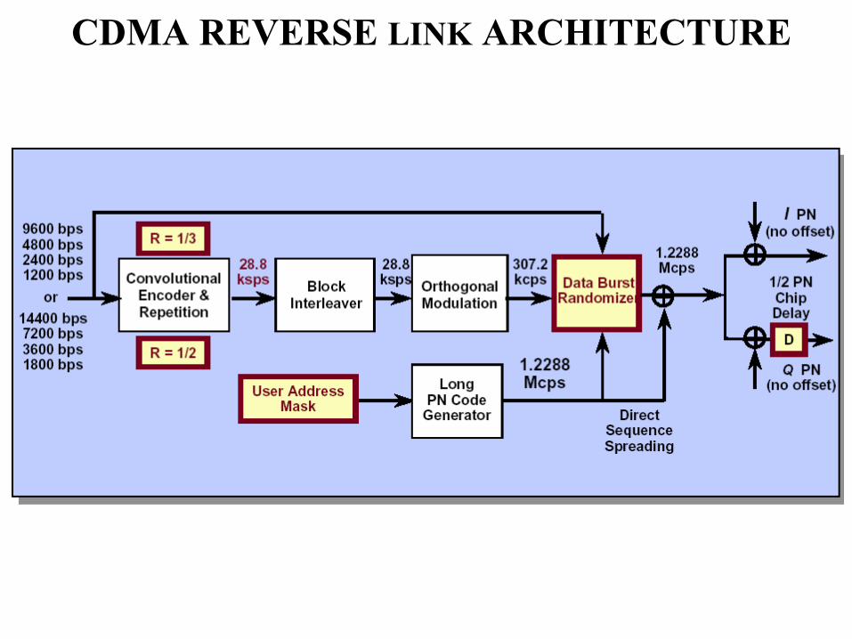
CDMA REVERSE LINK ARCHITECTURE

AIR INTERFACE
Control Channels
Downlink Uplink
Pilot Sync Paging Access

AIR INTERFACE
TRAFFIC CHANNELS
SPEECH or DATA ASSOCIATED SIGNALLING
1 1/2 1/4 1/8 Blank & Burst
Dim & Burst
Power Control
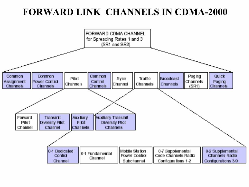
FORWARD LINK CHANNELS IN CDMA-2000

Forward Traffic Code Channel
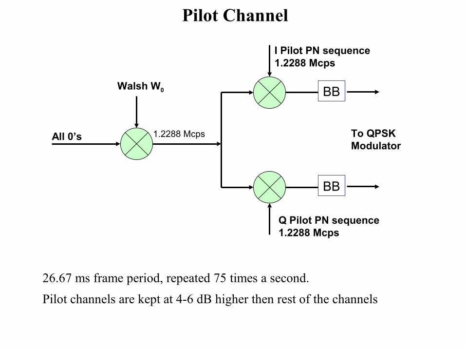
� 26.67 ms frame period, repeated 75 times a second.
� Pilot channels are kept at 4-6 dB higher then rest of the channels
BB
BB
All 0’s
Walsh W0
1.2288 Mcps
I Pilot PN sequence1.2288 Mcps
Q Pilot PN sequence1.2288 Mcps
To QPSKModulator
Pilot Channel

Sync Channel - W
Needed to achieve code synchronization and timing information.
Sync Channel Message includes : • System Identification
• Network Identification
• Supported protocol revision levels
• Pilot PN sequence offset index
• Long code state
• System time
• Leap seconds
• Offset local time
• Daylight savings time indicator
• Page channel data rate
64
32

� Convolutional encoder not zeroed out after each frame
� No CRC bits at frame level, SOM (Start Of Message)
SOM
31 Information Bits
32 bits / 26.67 ms
BB
BB
Sync ChannelMessage Walsh W32
1.2288Mcps
I Pilot PN sequence1.2288 Mcps
Q Pilot PN sequence1.2288 Mcps
To QPSKModulator
ConvolutionalEncoder
Rate=1/2, K=9
SymbolRepetition
1.2Kbps
2.4Ksps
BlockInter-leaver19.2
Ksps19.2Ksps
Sync Channel Frames

Page Channel - W Base station communicates with the mobiles during Idle Mode.
Page channel message includes :• System and access parameters
• Neighbor list
• Channel list
• Page
• Order
• Channel Assignment
• Data Burst
• Authentication challenge
• SSD (Shared Secret Data) update
• Feature notification
• Null
64
1-7

BB
BB
Paging ChannelMessage
Walsh W1-7
1.2288Mcps
I Pilot PN1.2288 Mcps
Q Pilot PN1.2288 Mcps
To QPSKModulator
ConvolutionalEncoder
Rate=1/2, K=9
SymbolRepetition
4.8/9.6Kbps
9.6/19.2Ksps
BlockInter-leaver19.2
Ksps
19.2Ksps
Long Code Decimator
Long Code Generator
1.2288Mcps
64:1Long-code MaskforPaging Channel
Paging Channel

To QPSKModulator
BB
Walsh Wn
1.2288Mcps
I Pilot PN1.2288 Mcps
Q Pilot PN1.2288 Mcps
ConvolutionalEncoder
Rate=1/2, K=9
SymbolRepetition
BlockInter-leaver 19.2
Ksps
DecimatorLong Code Generator
1.2288Mcps
64:1Long-code Mask
Decimator
Mux
24:1
Power ControlBits (800bps)
BB
Forward Traffic Channel

Reverse Link Code Channels

Reverse Link Code Channels
RFTransmit/Receive
Up/Down Converter
Searcher
Four Fingers
DemodulationProcessor
Deinterleaver&
Viterbi Decoder
P/NSequenceGenerator
Rx Data
Packets
Antenna

REVERSE LINK CHANNELS IN CDMA-2000

Reverse Link Walsh Code

Walsh Code Administration
Walsh Codes have to be Orthogonal
• Walsh codes on the same “row” are Non-Orthogonal
Reserved Walsh Codes
• F-PICH W064
• F-SYNC W3264
• F-PCH W164
• F-TDPICH W16128
• F-QPCH W30128
- 2nd and 3rd F-QPCH W48128 and W112
128
- Non-provisioned F-QPCH Walsh codes is available for traffic
Walsh Functions Lengths

Access Channel
Mobile communications with base station during Idle Mode
Access channel message includes :
• Registration
• Order
• Data Burst
• Origination
• Page response
• Authentication challenge response

• Tail Bits Zero Convolutional Encoder, No CRC Bits At Frame Level
• Preamble Comprised of Zero Filled Frames
88 Information Bits8 TailBits
20 ms
BB
BB
Access ChannelMessage
1.2288Mcps
I Pilot PN1.2288 Mcps
Q Pilot PN1.2288 Mcps
To QPSKModulator
ConvolutionalEncoder
Rate=1/3, K=9
SymbolRepetition
4.8/9.6Kbps
14.4Ksps
BlockInter-leaver28.8
Ksps
64-aryOrthogonalModulator
Long Code Generator
1.2288 McpsLong-code Mask
Access Channel Frames

BB
BB
1.2288Mcps
I Pilot PN1.2288 Mcps
Q Pilot PN1.2288 Mcps
To QPSKModulator
ConvolutionalEncoder
Rate=1/3, K=9
SymbolRepetition
RS1/RS2
BlockInter-leaver28.8
Ksps
64-aryOrthogonalModulator
Long Code Generator
1.2288 McpsLong-code
Mask
DataBurst
Randomizer
28.8Ksps
4.8Ksps
Reverse Traffic Channel


Access Channel 1 PNA Access Channel 2
PNB Access Channel nPNX Traffic Channel 1
PNH Traffic Channel 2PNI Traffic Channel 3
PNJ Traffic Channel m-1PNY Traffic Channel m
PNZ
All MS transmit on same frequency but with different PN codes to create different logical channels. Some channels
marked for Access are used for signaling and control.
Reverse Channel
SECTION 3CALL PROCESSING IN CDMA
Section Introduction
•Mobile Initialization•Mobile Registration•Handoff Types•Rake Receiver•Power Control•Vocoding

Overview of Call Processing

MOBILE TRANSITION INTO DIFFERENT STATES
Power - up
Mobile Initialization
State
Mobile IdleState
Mobile System AccessState
Mobile TrafficChannel
State
Mobile Idle Handoff or enable to receive Paging Channel.
Receives acknowledgement to an Access Channel transmission other than Origination or Page response I.e. registration acknowledgement.
Directed to a
Traffic
Channel
Receives Paging
Channel Message :
Originates a cell Registration
Mobile has fully acquired system timing.
Ends use of Traffic Channel

Signaling Services Layer
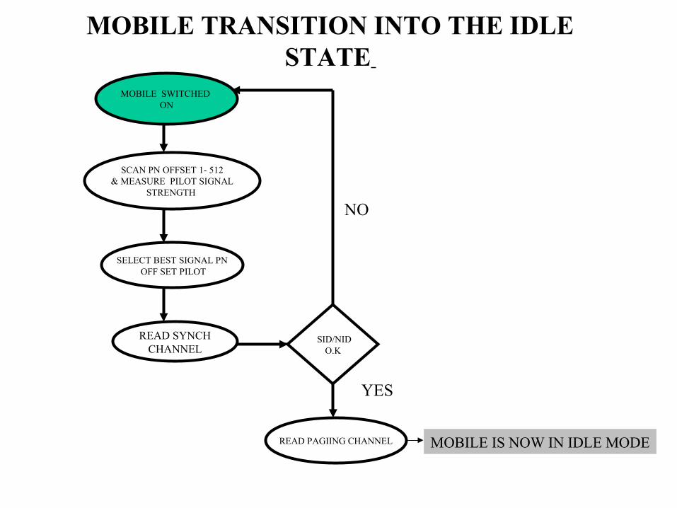
MOBILE TRANSITION INTO THE IDLE STATE
MOBILE SWITCHED ON
SCAN PN OFFSET 1- 512& MEASURE PILOT SIGNAL
STRENGTH
SELECT BEST SIGNAL PN OFF SET PILOT
READ SYNCHCHANNEL
SID/NIDO.K
READ PAGIING CHANNEL MOBILE IS NOW IN IDLE MODE
NO
YES

SYSTEM DETERMINATION SUBSTATE

NO
MOBILE- PILOT CHANNEL ACQUISITION SUBSTATE
1.SCAN ALL PILOTS

Sync Channel Acquisition Substate

Go to Paging Channel, Get Configured

Mobile Initialization State
Page Channel Monitor & Pilot search
Sub state
Mobile System Access
State
Idle Handoff Sub state
Mobile unable to receive Paging Channel
Mobile receives Acknowledgement to an Access transmission other than Origination or Page Response.
• Call Termination
• Call Origination
• Registration
Another pilot stronger than current pilot
Idle Handoff complete
Mobile has fully acquired system timing
Mobile Idle State

Idle State
System Parameters Message
Neighbor List
Access Parameters Message
CDMA Channel List Message
Global service Redirection Message
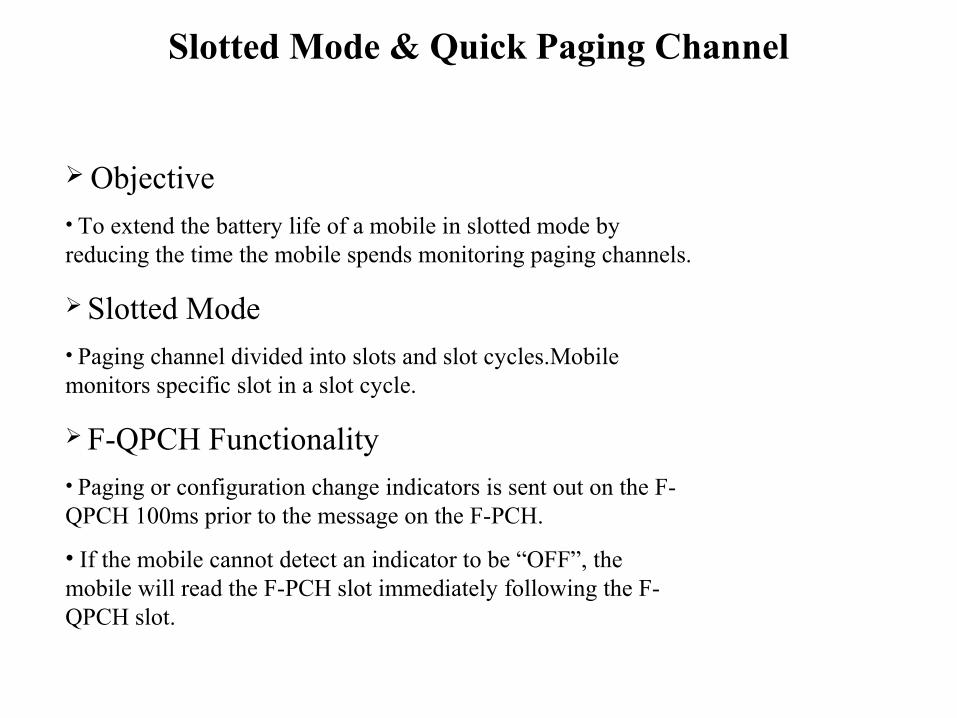
Slotted Mode & Quick Paging Channel
Objective• To extend the battery life of a mobile in slotted mode by reducing the time the mobile spends monitoring paging channels.
Slotted Mode• Paging channel divided into slots and slot cycles.Mobile monitors specific slot in a slot cycle.
F-QPCH Functionality• Paging or configuration change indicators is sent out on the F-QPCH 100ms prior to the message on the F-PCH.
• If the mobile cannot detect an indicator to be “OFF”, the mobile will read the F-PCH slot immediately following the F-QPCH slot.
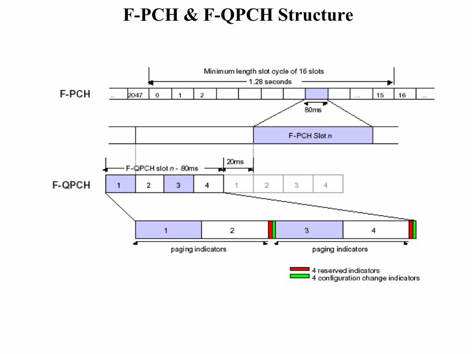
F-PCH & F-QPCH Structure

Access Channel Protocol
Used when mobile contact base station• Quickly
•Avoid Interference
Two protocols• Message or order response access
• Request access
Trial – and - error

Access Procedure

Access Handoff Features
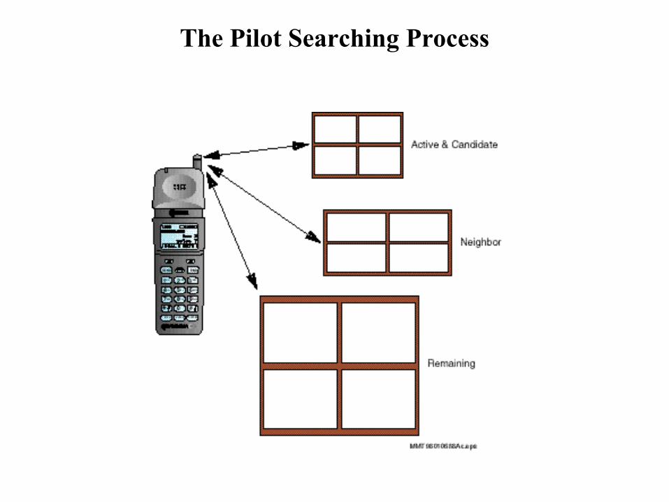
Mobile (MS) searching for pilots Active-,Neighbors-,Remaining State
Origination
MS perform access attempt.Up to 6 strongest pilots ind.
Active pilot in msg capsule
Access Handoff
Mobile Traffic Channel State
Channel Assignment intoSoft Handoff (CAMSHO)
BS sends generalPage to MS
Access EntryHandoff
No
Yes

The Traffic Channel State
From Mobile SystemAccess State
TrafficChannel
InitializationSub state
Waiting forOrder
Sub state
ConversationSub state
Waiting forMobileAnswer
Sub state
ReleaseSub state
To MobileInitialization State
MS cell origination MS
receives an Acknowledge
Order on forward Traffic
Channel
MS user disconnects or MS receives
Release Order
MS receives an Alert Order
MS receives Release Order
MS user Answers
call
MS call termination MS receives an Acknowledge Order on forward traffic
channel
MS receives Release Order

Traffic Channel Assignment Algorithm
Access seizure received on carrier frequency Fk
Calculate downlink loading for F1,F2,…Fk….,Fn normalized
on max_power
Subtract tca_weight from downlink Loading for Fk
Select RF carrier frequency withAvailable traffic channel elements,available packet pipe capacity, and
minimum downlink loading.
Example:
tca _weight = 20
F1 : 30%
F2 : 45% (originating carrier)
F2 vs. F1 : (45-20=25) vs. 30
Traffic Channel assigned to F2
Called Cross Carrier Frequency
Traffic Channel Assignment when selected RF carrier frequency = Fk

Traffic Channel Associated Signaling
When on a traffic channel, associated signaling is used for communication of messages between mobile and base station.
In addition to certain messages transmitted in Idle Mode, other messages are send on the traffic channel :
• Handoff direction
• In-traffic system parameters
• Neighbor list update
• Mobile station registered
• Pilot strength measurement
• Power measurement report
• Handoff completion

Conversation Substate
Messages being sent on the traffic channel
Continuous confirmation of the traffic channel
Locating handoff candidates
Performing handoffs
Power control
Overload control
Other call activities

The Traffic Channel State
Signaling or Secondary Traffic
1 1 2 80 bits 88 bits 12 bits 8 bits
MM 1
TT 0
TM 00
Primary Traffic
CRC Tail
Rate ½ Primary +
Signaling
1 1 2 40 bits 128 bits 12 bits 8 bits
MM 1
TT 0
TM 01
Primary Traffic
CRC Tail
Rate 1/4 Primary +
Signaling Signaling or Secondary Traffic
1 1 2 16 bits 152 bits 12 bits 8 bits
MM 1
TT 0
TM 10
Primary Traffic
CRC Tail
Rate 1/8 Primary +
Signaling Signaling or Secondary Traffic
1 1 2 168 bits 12 bits 8 bits
MM 1
TT 0
TM 11
CRC Tail
Blank and Burst
Signaling Traffic
MM = Mixed Mode
0 = Primary Only
1= Primary + Signaling or Secondary
TT = Traffic Type
0 = Signaling
1 = Secondary
TM = Traffic Mode
00 = 80/88
01 = 40/128
10 =16/152
11= 168

Overview of Registration
•NAME•MIN•ESN•Location •Desired Slot Cycle•Station Class Mark•Billing Information

Types of Registration
Power Up
Power Down
Timer Based
Distance Based
Zone Based
Parameter Change
Ordered
Implicit
Traffic Channel

CDMA2000 Handoff Related to Call Processing States
Idle Handoff Access Entry Handoff **
Dormant Handoff
Dormant Handoff
Access Probe HandoffAccess Handoff
Idle State
Update Overhead Information SubstateSystem
Access States Allowed
Handoff Types
Mobile States
Page Response or Origination or
Order/Message Response Substate
Channel Assignment Message or Extended Channel Assignment Message Received
Mobile Station Control on the Traffic Channel
State
Request or Response to send
on Access Channel
Dormant HandoffSoft Handoff
Softer Handoff
Soft Handoff Softer Handoff Hard Handoff
Dormant Handoff
**Access Entry Handoff allowed after receiving a message requiring a response or acknowledgment

Idle Handoffs
A
B
Pilot_B > Pilot_A + 3
dB Must Handoff

Access Handoffs
TIA/EIA-95
Improvements
Perform Idle Handoff here if required
Tx strength of several neighbors
Perform Idle Handoff between probes if necessary
Perform Idle Handoff between probes if necessary
Access Handoff
Channel Assignment into Soft Handoff
Receipt of Page or Subscriber dials #
Update Overhead Information
Begin Access Attempt (TX of 1st Probe)
Continuous Access Attempt(TX of 2nd Probe)
Continuous Access Attempt (TX of 3rd Probe)
Channel Assignment Message
Probe is Acknowledged
IDLE STATE
ACCESSSTATE

Soft Handoffs

F1/F2/F3
F1/F2
F1(Common Carrier)
Carrier is discontinuing – border carrier
Current carrier is blocked – handoff escalation
Why Inter- Frequency Handoff ?
F1/F2/F3Traffic
Cell
F1/F2/F3Traffic
Cell
F1/F2/F3Traffic
Cell
F1/F2/F3Traffic
Cell
F1/F2Traffic
F3 BorderCell
F1/F2Traffic
F3 BorderCell
F1/F2Traffic
Cell
F1/F2Traffic
Cell
F1TrafficF2 Border
Cell
F1Traffic
Cell
F1TrafficF2 Border
Cell
F1Traffic
Cell

Traffic Channel Handoffs
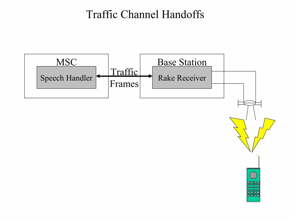
Traffic Channel Handoffs
Speech Handler
MSC
Rake Receiver
Base StationTraffic Frames

Traffic Channel Handoffs

Semi-Soft vs. Hard Handoff
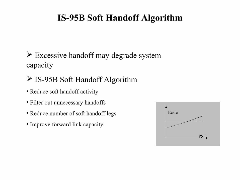
IS-95B Soft Handoff Algorithm
Excessive handoff may degrade system capacity
IS-95B Soft Handoff Algorithm• Reduce soft handoff activity
• Filter out unnecessary handoffs
• Reduce number of soft handoff legs
• Improve forward link capacity
Ec/Io
PS1
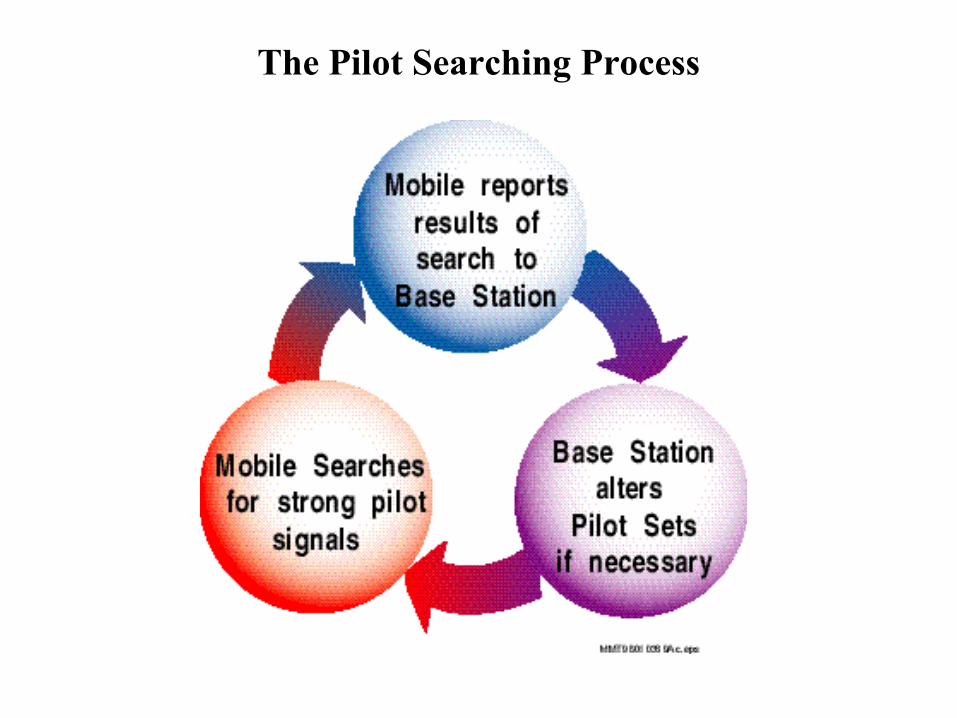
The Pilot Searching Process
The Pilot Searching Process

The Pilot Searching Process

The Pilot Searching Process

Handoff Signaling

Handoff Signaling

Why Power Control ?
Objectives
• Maintain QOS
• Maximize capacity
• Minimize interference
Power Control Algorithms
• Forward Link Power Control (FLPC,FPC)
- a.k.a Downlink Power Control
• Reverse Link Power Control (RPLC,RPC)
- a.k.a.Uplink Power Control

Near-far Problem Path Loss Fading Performance Objectives
Power Control Is Required ?

Power Control
Mobile Tx Power (dBm) =
OPEN LOOPk-Mobile Receive Power (dBm)
+ Parameters+ Access robe Corrections (dB)
+ CLOSED LOOP Corrections (dB)

Reverse Link Power Control
Two separate algorithms
Reverse Open Loop (Autonomous Control)• Performed in the mobile
• Adjust for pathloss
- Output power based on received signal strength
- Tx power = - [Mean Received Signal Strength] + correction_factors
Reverse Closed Loop (Base Station Directed Control)•Base station directs mobile to adjust power
•Controls frame error rate of signal received at the serving base station
•Consists of an inner loop and an outer loop

Reverse Link Closed Loop Power Control
Base station sends power control bits
• 800 controls per second (800 Hz)
Closed Outer Loop (at base station)
• Calculates Ec/Io set point (for R-PICH)
- Based on R-FCH frame error rate
Closed Inner Loop (at base station)•Compare Ec/Io set point with measured Ec/Io
- Send power control bits (up/down) to mobile
Mobile Adjust its power•Based on power control bits from base station
•Step size of is adjustable

Forward Link Power Control
Reverse Link Closed Lop process is adopted
Mobile sends power control bits on R-PICH• 800 control per second (800 Hz)
• Based on Eb/Nt and FER objectives
Base station received power control bits• Variable power step size controlled by the base station

The Rake Receiver

Multipath

Multipath
Correlator 1
Correlator 2
Correlator 3
SearcherCorrelator
COMBINER

Variable Rate Vocoding & Multiplexing

Coding & Compressing
8000 samples/ s. 64 kbps
Sile
nce
Sile
nce
Coding & compression 14.4 kbps Decoding & decompression
Optimally reconstructed human voice
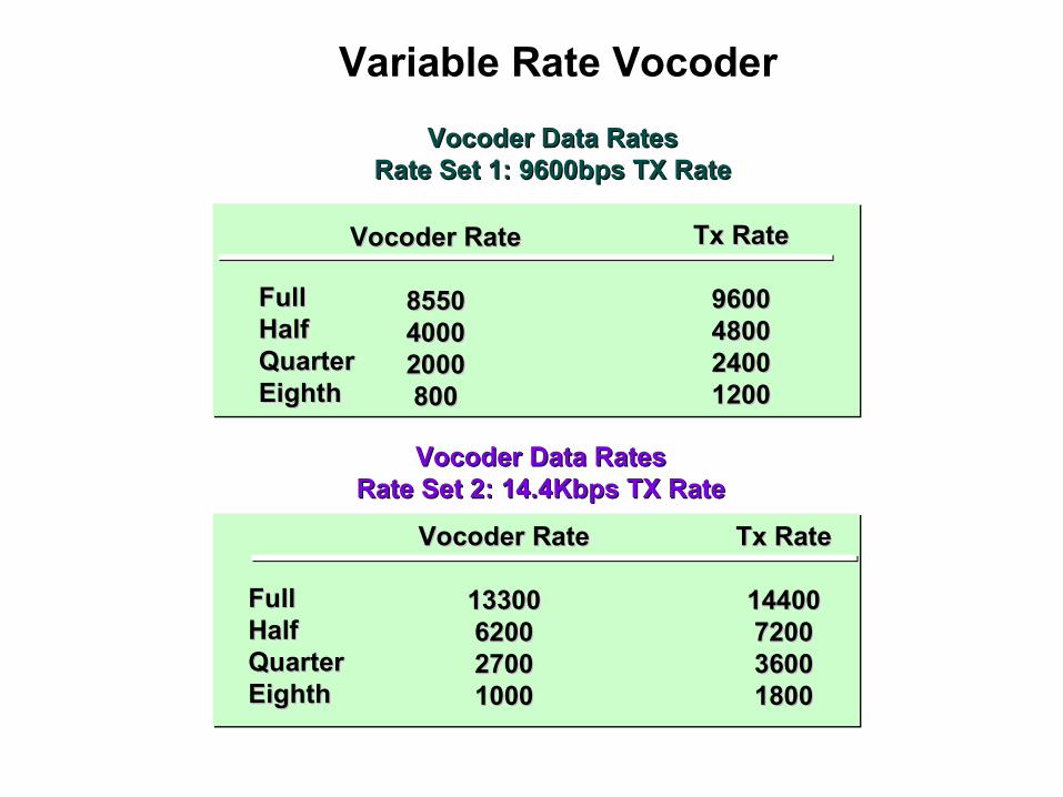
Variable Rate Vocoder
Vocoder Data RatesVocoder Data RatesRate Set 1: 9600bps TX RateRate Set 1: 9600bps TX Rate
Vocoder RateVocoder Rate
855085504000400020002000800800
Tx RateTx Rate
96009600480048002400240012001200
FullFullHalfHalfQuarterQuarterEighthEighth
Vocoder Data RatesVocoder Data RatesRate Set 2: 14.4Kbps TX RateRate Set 2: 14.4Kbps TX Rate
Vocoder RateVocoder Rate
1330013300620062002700270010001000
Tx RateTx Rate
1440014400720072003600360018001800
FullFullHalfHalfQuarterQuarterEighthEighth

Variable Rate Vocoder
24 bits 48 bits 96 bits 96bits 192 bits
20 msec 20 msec 20 msec 20 msec 20 msec
Eight
Rate
Quarter
Rate
Half
Rate
Half
Rate
Full
Rate

Rate Set 1
8 Tail bits1 171 bits 12 bit CRC
Mode Bit
Full Rate
80 bits 8 bit CRC 8 Tail bitsHalf Rate
8 Tail bits40 bitsQuarter Rate
16 bits 8 Tail bitsEighth Rate
Rate Sets

Multiplexing
Signaling or Secondary Traffic
1 1 2 80 bits 88 bits 12 bits 8 bits
MM 1
TT 0
TM 00
Primary Traffic
CRC Tail
Rate ½ Primary +
Signaling
1 1 2 40 bits 128 bits 12 bits 8 bits
MM 1
TT 0
TM 01
Primary Traffic
CRC Tail
Rate 1/4 Primary +
Signaling Signaling or Secondary Traffic
1 1 2 16 bits 152 bits 12 bits 8 bits
MM 1
TT 0
TM 10
Primary Traffic
CRC Tail
Rate 1/8 Primary +
Signaling Signaling or Secondary Traffic
1 1 2 168 bits 12 bits 8 bits
MM 1
TT 0
TM 11
CRC Tail
Blank and Burst
Signaling Traffic
MM = Mixed Mode
0 = Primary Only
1= Primary + Signaling or Secondary
TT = Traffic Type
0 = Signaling
1 = Secondary
TM = Traffic Mode
00 = 80/88
01 = 40/128
10 =16/152
11= 168

Multiplexing
1 124 bits 10 bits 8 bits
MM= 0
Primary Traffic CRC Tail
7200 bps Primary Traffic Only
1 3 54 bits 67 bits 10 bits 8 bits
MM= 1
FM= 000
Primary Traffic CRC TailSignaling Traffic
7200 bps Dim and Burst with rate 1/4
Primary and Signaling Traffic
1 3 20 bits 242 bits 10 bits 8 bits
MM= 1
Primary Traffic CRC TailSignaling Traffic
7200 bps Dim and Burst with rate 1/8
Primary and Signaling Traffic
FM= 001
MM= 1
1 3 121 bits 10 bits 8 bits
CRC TailSignaling Traffic
7200 bps Blank and Burst with Signaling
Traffic FM= 010

Muliplexing
MM= 0
1 54 bits 10 bits 8 bits
Primary Traffic CRC Tail
3600 bps Primary Traffic only
1 2 20 bits 32 bits 8 bits 8 bits
MM= 1
Primary Traffic CRC TailSignaling Traffic
3600 bps Dim and Burst with rate 1/8
Primary and Signaling Traffic FM=
000
MM= 1
1 2 52 bits 8 bits 8 bits
CRC TailPrimary Traffic
3600 bps Blank and Burst with Signaling
Traffic FM= 01

SECTION 4INTRODUCTION TO DATA IN CDMA
Section Introduction•DATA Layers•Data and Quality•FCH and SCH •Dormant Mode•MAC and RLP•SARA

MAC and LAC Protocol Layers

Protocol Layers
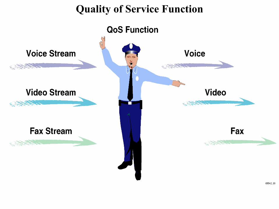
Quality of Service Function

Radio Link Protocol

Packet Data Traffic
Packet data is bursts of data followed by periods of inactivity
Resources from instantaneously inactive users are reassigned
Inherently a best – effort system
• The system makes the best effort to provide an adequate service to multiple users consistent with scheduling policies and user priorities.

Statistical Gain

Queuing Delay

3G-1X Airlink Overview
. . .
Su
pp
lem
en
tal c
ha
nn
els
InactivityTimer
InactivityTimer
Session EndPPP Disconnect
Data CallReconnections
time
FundamentalChannel
Burst Burst BurstDormant
Data CallOrigination
Data Session
Data Call Data CallData Call
Fundamental Channel - 9.6 KbpsSupplemental Channel - 19.2 - 153.6 Kbps

3G1X Call
Supplemental Air Recourse Allocation
• SARA determines data rate and burst duration of SCH
- Goal is to maximize throughput based on QoS objectives
• First maximum data rate is determined
- Channel elements, Walsh codes, packet pipes etc.
• Then data rate and burst duration
- Maximum data rate and RF conditions.

Supplemental Channels - Configuration
• No SCH
- Voice and low speed data
• Dedicated SCH
- High speed packet or circuit data for one user per SCH at a time
• Shared SCH
- High speed packet data for multiple users on one or more SCHs

Shared Supplemental Channel

Dedicated Supplemental Channel

Accumulative Interference

Data Call With Supplemental Channel

Turbo encoder
-“Two convolution encoders operating in parallel”
Input: turbo interleave
Output:concatenated, repetition and puncturing
-More robust than convolution codes
- Add additional delay to the traffic data
Complex Scrambling

CDMA Capacity

Coverage
(Eb/Io) = (Eb/Io) + Marginreceived required
Strong coding enables operation at lower Eb/Io.
Soft Handoff enables CDMA to provide acceptable level of service with smaller margin.

Radio Frequency Impairments
Total impairment = Thermal noise NO
+ Co – channel interference from
mobiles served by the same
physical antenna face
+ Co – channel interference from
mobiles served by nearby
physical antenna faces
NT
Thermal noise = NO
Total impairment = NT

Reverse Link Pole Capacity

Example 3G-1X Reverse Link Budget Voice
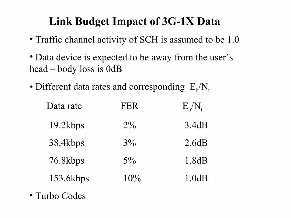
Link Budget Impact of 3G-1X Data
• Traffic channel activity of SCH is assumed to be 1.0
• Data device is expected to be away from the user’s head – body loss is 0dB
• Different data rates and corresponding Eb/Nt
Data rate FER Eb/Nt
19.2kbps 2% 3.4dB
38.4kbps 3% 2.6dB
76.8kbps 5% 1.8dB
153.6kbps 10% 1.0dB
• Turbo Codes

Example 3G-1X Reverse Link Budget-Data________
