cdm-840 manual
TRANSCRIPT

Part Number MN-CDM840 / CD-CDM840 Revision 3
IMPORTANT NOTE: The information contained in this document supersedes all previously published information regarding this product. Product specifications are subject to change without prior notice.
CDM-840 Advanced VSAT Series Remote Router
Installation and Operation Manual For Firmware Version 1.6.2.X or higher

ER-CDM840-EA3 Rev - PLM C-0033932
Errata A for MN-CDM840 Rev 3
Comtech EF Data Documentation Update
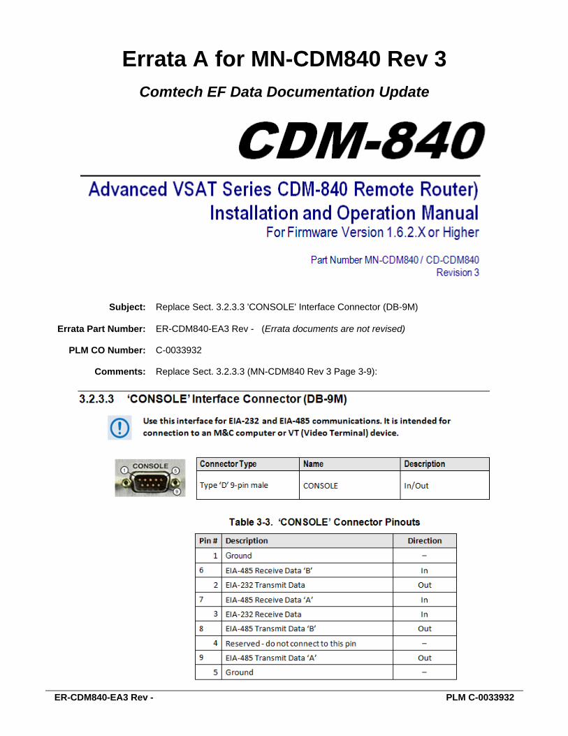
Subject: Replace Sect. 3.2.3.3 'CONSOLE' Interface Connector (DB-9M)
Errata Part Number: ER-CDM840-EA3 Rev - (Errata documents are not revised)
PLM CO Number: C-0033932
Comments: Replace Sect. 3.2.3.3 (MN-CDM840 Rev 3 Page 3-9):

ER-CDM840-EA3 Rev - PLM C-0033932
BLANK PAGE

Copyright © 2015 Comtech EF Data. All rights reserved. Printed in the USA. Comtech EF Data, 2114 West 7th Street, Tempe, Arizona 85281 USA, 480.333.2200, FAX: 480.333.2161
CDM-840 Advanced VSAT Series CDM-840 Remote Router)
Installation and Operation Manual For Firmware Version 1.6.2.X or Higher
Part Number MN-CDM840 / CD-CDM840
Revision 3

BLANK PAGE
iii
TABLE OF CONTENTS TABLE OF CONTENTS ............................................................................................................III
TABLES ................................................................................................................................. XIII
FIGURES ................................................................................................................................ XIII
PREFACE .............................................................................................................................. XVII
About this Manual ......................................................................................................................... xvii Related Documents ................................................................................................................................ xvii
Conventions and References ......................................................................................................... xviii Patents and Trademarks ....................................................................................................................... xviii Warnings, Cautions, and Notes ............................................................................................................. xviii Examples of Multi-Hazard Notices ........................................................................................................ xviii Recommended Standard Designations ................................................................................................. xviii
Safety and Compliance .................................................................................................................... xix Electrical Safety and Compliance ............................................................................................................ xix Electrical Installation ............................................................................................................................... xix Operating Environment .......................................................................................................................... xix European Union Radio Equipment and Telecommunications Terminal Equipment (R&TTE) Directive (1999/5/EC) and EN 301 489-1 .............................................................................................. xx
European Union Electromagnetic Compatibility (EMC) Directive (2004/108/EC) ......................... xx European Union Low Voltage Directive (LVD) (2006/95/EC) ............................................................... xx European Union RoHS Directive (2002/95/EC) ................................................................................... xxi European Union Telecommunications Terminal Equipment Directive (91/263/EEC) ........................ xxi CE Mark ............................................................................................................................................... xxi
Product Support .............................................................................................................................. xxi
Comtech EF Data Headquarters ....................................................................................................... xxi
Warranty Policy ............................................................................................................................. xxii Limitations of Warranty ......................................................................................................................... xxii Exclusive Remedies ............................................................................................................................... xxiii
CHAPTER 1. INTRODUCTION ............................................................................................ 1–1
1.1 Overview ............................................................................................................................ 1–1
1.2 Functional Description ........................................................................................................ 1–2

CDM-840 Remote Router MN-CDM840 / CD-CDM840 Table of Contents Revision 3
iv
1.3 Features ............................................................................................................................. 1–4 1.3.1 Physical Description .................................................................................................................. 1–4
1.3.1.1 Standard Assemblies ......................................................................................................... 1–4 1.3.1.2 Optional Assemblies .......................................................................................................... 1–4
1.3.2 Dimensional Envelope .............................................................................................................. 1–5 1.3.3 Physical Features ...................................................................................................................... 1–6
1.3.3.1 Front Panel Features ......................................................................................................... 1–6 1.3.3.2 Rear Panel Features .......................................................................................................... 1–7
1.3.3.2.1 Rear Panel Standard Features..................................................................................... 1–8 1.3.3.2.2 Rear Panel Optional Features ..................................................................................... 1–8
1.3.4 On-site Firmware Updates ........................................................................................................ 1–9 1.3.5 On-site Operational Upgrades .................................................................................................. 1–9 1.3.6 Monitor and Control Interfaces ................................................................................................ 1–9
1.4 Specifications .................................................................................................................... 1–10 1.4.1 Product Features .................................................................................................................... 1–10 1.4.2 Physical, Power, and Environmental ...................................................................................... 1–10 1.4.3 Modulator ............................................................................................................................... 1–11
1.4.3.1 Transmit .......................................................................................................................... 1–11 1.4.3.2 Block Up Converter (BUC) Support ................................................................................. 1–12
1.4.4 Demodulator ........................................................................................................................... 1–12 1.4.4.1 Receive ............................................................................................................................ 1–12 1.4.4.2 Low Noise Block Down Converter (LNB) Support ........................................................... 1–13
1.4.5 BER (Bit Error Rate) ................................................................................................................. 1–14 1.4.5.1 BER Monitor Functions ................................................................................................... 1–14
1.4.6 Regulatory Compliance ........................................................................................................... 1–14
CHAPTER 2. INSTALLATION ............................................................................................. 2–1
2.1 Unpack and Inspect the Shipment ....................................................................................... 2–1
2.2 Install the Unit Into a Rack Enclosure ................................................................................... 2–2 2.2.1 Install the Optional Rear Support Brackets Kit ......................................................................... 2–3
CHAPTER 3. REAR PANEL CONNECTIONS ..................................................................... 3–1
3.1 Overview – Cabling Connection Types ................................................................................. 3–1
3.2 CDM-840 Cabling Connections ............................................................................................. 3–5 3.2.1 IF Connector Group .................................................................................................................. 3–6
3.2.1.1 ‘L-BAND Rx’ IF Connector .................................................................................................. 3–6 3.2.1.2 ‘L-BAND Tx’ IF Connector .................................................................................................. 3–6
3.2.2 Terrestrial Data Connector Group ............................................................................................ 3–7 3.2.2.1 ‘G.703 | OUT / IN’ Connectors .......................................................................................... 3–7 3.2.2.2 ‘ETHERNET | TRAFFIC | GE’ (Gigabit Ethernet) Connector (RJ-45F) ................................. 3–7
3.2.3 Utility Connector Group ........................................................................................................... 3–8 3.2.3.1 ‘ETHERNET | MANAGEMENT | FE’ (Fast Ethernet) Connector (RJ-45F) ........................... 3–8
CDM-840 Remote Router MN-CDM840 / CD-CDM840 Table of Contents Revision 3
v
3.2.3.2 ‘REDUNDANCY’ Interface Connector (DB-9F) (FUTURE) ................................................... 3–8 3.2.3.3 ‘CONSOLE’ Interface Connector (DB-9M) ......................................................................... 3–9 3.2.3.4 ‘ALARMS’ Interface Connector (DB-15M) ....................................................................... 3–10
3.3 CDM-840 Ground and Power Connections ......................................................................... 3–11 3.3.1 Common Chassis Ground Interface ........................................................................................ 3–11 3.3.2 115V/230V Alternating Current (AC) Power Interface (Standard) ......................................... 3–12
3.3.2.1 AC Operation – Apply Power .......................................................................................... 3–12 3.3.2.2 AC Operation – Replace the Fuses ................................................................................. 3–13
3.3.3 -48V Direct Current (DC) Power Interface (Optional) ............................................................. 3–14 3.3.3.1 DC Operation – Apply Power .......................................................................................... 3–14 3.3.3.2 DC Operation – Replace the Fuses .................................................................................. 3–15
CHAPTER 4. UPDATING FIRMWARE ................................................................................ 4–1
4.1 Firmware Update Overview ................................................................................................ 4–1
4.2 Getting Started: Prepare for the Firmware Download .......................................................... 4–2
4.3 Download and Extract the Firmware Update ....................................................................... 4–6
4.4 Perform the Ethernet FTP Upload Procedure ....................................................................... 4–8
CHAPTER 5. FAST ACTIVATION PROCEDURE................................................................ 5–1
5.1 FAST Overview .................................................................................................................... 5–1
5.2 FAST Activation via the HTTP Interface ................................................................................ 5–2 5.2.1 FAST Configuration ................................................................................................................... 5–3 5.2.2 FAST Upgrade ........................................................................................................................... 5–4
CHAPTER 6. ETHERNET-BASED REMOTE PRODUCT MANAGEMENT ......................... 6–1
6.1 Overview ............................................................................................................................ 6–1
6.2 Ethernet Management Interface Protocols .......................................................................... 6–2 6.2.1 Ethernet Management Interface Access .................................................................................. 6–2 6.2.2 SNMP Interface ......................................................................................................................... 6–3
6.2.2.1 Management Information Base (MIB) Files ...................................................................... 6–3 6.2.2.2 SNMP Community Strings ................................................................................................. 6–4
6.2.3 HTTP (Web Server) Interface .................................................................................................... 6–4 6.2.3.1 User Login ......................................................................................................................... 6–4 6.2.3.2 HTTP Interface – Operational Features............................................................................. 6–5
6.2.3.2.1 Virtual Front Panel ...................................................................................................... 6–5 6.2.3.2.1.1 Virtual Front Panel LEDs ...................................................................................... 6–6
6.2.3.2.2 Navigation ................................................................................................................... 6–7 6.2.3.2.3 Page Sections .............................................................................................................. 6–8

CDM-840 Remote Router MN-CDM840 / CD-CDM840 Table of Contents Revision 3
vi
6.2.3.2.4 Action Buttons ............................................................................................................ 6–8 6.2.3.2.5 Drop-down Lists .......................................................................................................... 6–8 6.2.3.2.6 Text or Data Entry ....................................................................................................... 6–8
6.2.3.3 HTTP Interface Menu Tree Diagram ................................................................................. 6–9
6.3 HTTP Interface Page Descriptions ...................................................................................... 6–10 6.3.1 Home Pages ............................................................................................................................ 6–10
6.3.1.1 Home | Home ................................................................................................................. 6–10 6.3.1.2 Home | Contact ............................................................................................................... 6–11
6.3.2 Admin (Administration) Pages ................................................................................................ 6–12 6.3.2.1 Admin | Access................................................................................................................ 6–12 6.3.2.2 Admin | SNMP ................................................................................................................ 6–13 6.3.2.3 Admin | FAST .................................................................................................................. 6–14 6.3.2.4 Admin | Firmware ........................................................................................................... 6–15 6.3.2.5 Admin | Auto Logout ...................................................................................................... 6–16 6.3.2.6 Admin | VMS ................................................................................................................... 6–17
6.3.3 Configuration Pages ................................................................................................................ 6–19 6.3.3.1 Configuration | Interface Pages ...................................................................................... 6–19
6.3.3.1.1 Configuration | Interface | Fe Mgt ........................................................................... 6–19 6.3.3.1.2 Configuration | Interface | GE .................................................................................. 6–20 6.3.3.1.3 Configuration | Interface | E1 Pages ........................................................................ 6–22
6.3.3.1.3.1 Configuration | Interface | E1 | Configuration.................................................. 6–22 6.3.3.1.3.2 Configuration | Interface | E1 | Time Slots ....................................................... 6–24
6.3.3.2 Configuration | WAN pages ............................................................................................ 6–25 6.3.3.2.1 Configuration | WAN | Demod Pages ...................................................................... 6–25
6.3.3.2.1.1 Configuration | WAN | Demod | Config ............................................................ 6–25 6.3.3.2.1.2 Configuration | WAN | Demod | ACM (Adaptive Coding and Modulation) ..... 6–30
6.3.3.2.2 Configuration | WAN | Mod (Modulator) Pages ...................................................... 6–32 6.3.3.2.2.1 Configuration | WAN | Mod | Config ................................................................ 6–32 6.3.3.2.2.2 Configuration | WAN | Mod | ACM .................................................................. 6–36 6.3.3.2.2.3 Configuration | WAN | Mod | DPC .................................................................... 6–38
6.3.3.2.3 Configuration | WAN | QoS (Quality of Service) ...................................................... 6–40 6.3.3.2.3.1 Page Functionality Common for all QoS Control Modes ................................... 6–41 6.3.3.2.3.2 Page Functionality Specific to Active QoS Mode ............................................... 6–44
6.3.3.2.4 Configuration | WAN | Label .................................................................................... 6–48 6.3.3.2.5 Configuration | WAN | Compression ....................................................................... 6–49 6.3.3.2.6 Configuration | WAN | BUC (Block Up Converter) ................................................... 6–50 6.3.3.2.7 Configuration | WAN | LNB (Low Noise Block Down Converter) ............................. 6–52
6.3.3.3 Configuration | Network Pages ...................................................................................... 6–53 6.3.3.3.1 Configuration | Network | Routing Pages ................................................................ 6–53
6.3.3.3.1.1 Configuration | Network | Routing | Routes .................................................... 6–53 6.3.3.3.1.2 Configuration | Network | Routing | IGMP ....................................................... 6–55 6.3.3.3.1.3 Configuration | Network | Routing | DHCP....................................................... 6–57
6.3.3.3.2 Configuration | Network | ARP ................................................................................ 6–58 6.3.3.3.3 Configuration | Network | Working Mode ............................................................... 6–59 6.3.3.3.4 Configuration | Network | DNS ................................................................................ 6–60
6.3.3.4 Configuration | ECM (Entry Channel Mode) ................................................................... 6–61

CDM-840 Remote Router MN-CDM840 / CD-CDM840 Table of Contents Revision 3
vii
6.3.3.5 Configuration | dSCPC (Dynamic Single Carrier per Channel) ........................................ 6–64 6.3.4 Status Pages ............................................................................................................................ 6–66
6.3.4.1 Status | Statistics Pages .................................................................................................. 6–66 6.3.4.1.1 Status | Statistics | Traffic ........................................................................................ 6–66 6.3.4.1.2 Status | Statistics | Network / Router ...................................................................... 6–68 6.3.4.1.3 Status | Statistics | Compression.............................................................................. 6–69 6.3.4.1.4 Status | Statistics | QoS ............................................................................................ 6–70
6.3.4.1.4.1 Page Functionality Common for all QoS Control Modes ................................... 6–71 6.3.4.1.4.2 Page Functionality Specific to Active QoS Control Mode .................................. 6–72
6.3.4.1.5 Status | Statistics | E1 Pages (CDM-840 only) .......................................................... 6–73 6.3.4.1.5.1 Status | Statistics | E1 | Transmit ...................................................................... 6–73 6.3.4.1.5.2 Status | Statistics | E1 | Receive........................................................................ 6–74
6.3.4.1.6 Status | Statistics | Trending (CDM-840 only) .......................................................... 6–76 6.3.4.2 Status | Monitor Pages ................................................................................................... 6–78
6.3.4.2.1 Status | Monitor | Events ......................................................................................... 6–78 6.3.4.2.2 Status | Monitor | Alarms ........................................................................................ 6–79
6.3.5 Utility Pages ............................................................................................................................ 6–81 6.3.5.1 Utility | Utility ................................................................................................................. 6–81 6.3.5.2 Utility | Carrier ID ............................................................................................................ 6–84 6.3.5.3 Utility | Reboot ............................................................................................................... 6–85
CHAPTER 7. SERIAL-BASED REMOTE PRODUCT MANAGEMENT ............................... 7–1
7.1 Overview ............................................................................................................................ 7–1
7.2 Remote Commands and Queries Overview .......................................................................... 7–3 7.2.1 Basic Protocol ........................................................................................................................... 7–3 7.2.2 Packet Structure ....................................................................................................................... 7–4
7.2.2.1 Start of Packet ................................................................................................................... 7–5 7.2.2.2 Target Address .................................................................................................................. 7–5 7.2.2.4 Instruction Code ................................................................................................................ 7–5 7.2.2.5 Instruction Code Qualifier ................................................................................................. 7–5
7.2.2.5.1 Controller-to-Target Instruction Code Qualifiers ....................................................... 7–6 7.2.2.5.2 Target-to-Controller Instruction Code Qualifiers ....................................................... 7–6
7.2.2.6 Optional Message Arguments ........................................................................................... 7–7 7.2.2.7 End of Packet .................................................................................................................... 7–8
7.3 Remote Commands and Queries ......................................................................................... 7–9 7.3.1 Table Indexes ............................................................................................................................ 7–9 7.3.2 Transmit (Tx) Parameters Commands and Queries................................................................ 7–12 7.3.3 Receive (Rx) Parameters Commands and Queries ................................................................. 7–14 7.3.4 Demodulator Status Commands and Queries ........................................................................ 7–16 7.3.5 Transmit (Tx) BERT Command or Query ................................................................................. 7–17 7.3.6 Receive (Rx) BERT Command or Query .................................................................................. 7–17 7.3.7 BUC (Block Up Converter) Parameters Commands and Queries ........................................... 7–17 7.3.8 LNB (Low-Noise Block Down Converter) Parameters Commands and Queries ..................... 7–21 7.3.9 Unit Parameters Commands and Queries .............................................................................. 7–22

CDM-840 Remote Router MN-CDM840 / CD-CDM840 Table of Contents Revision 3
viii
7.3.10 Bulk Configuration String Commands ..................................................................................... 7–29 7.3.11 Redundancy Commands and Queries .................................................................................... 7–30 7.3.12 Vipersat Management System (VMS) Commands and Queries ............................................. 7–31 7.3.13 Entry Channel Mode (ECM) Commands and Queries............................................................. 7–32 7.3.14 Miscellaneous Utility Commands and Queries ....................................................................... 7–33
APPENDIX A. REFERENCE DOCUMENTATION .............................................................. A–1
A.1 Overview ........................................................................................................................... A–1
A.2 FEC (Forward Error Correction) Options .............................................................................. A–2
A.3 ACM/VCM (Adaptive Coding and Modulation / Variable Coding and Modulation) Operation ..... .......................................................................................................................................... A–3
A.4 BPM (Bridge Point-to-Multipoint) Operation ...................................................................... A–4
A.5 ECM (Entry Channel Mode) Operation ................................................................................ A–5
A.6 dMesh (VMS Dynamic Mesh) Connectivity .......................................................................... A–6
A.7 DPC (VMS Dynamic Power Control) Operation .................................................................... A–7
APPENDIX B. FEC (FORWARD ERROR CORRECTION) OPTIONS ................................ B–1
B.1 FEC Overview ...................................................................................................................... B–1
B.2 DVB-S2: LDPC and BCH ........................................................................................................ B–1 B.2.1 Range of Data Rates.................................................................................................................. B–2 B.2.2 BER, QEF, Eb/No, Es/No Spectral Efficiency, and Occupied Bandwidth .......................................... B–2
B.3 VersaFEC (Short-block LDPC) ............................................................................................... B–3 B.3.1 Range of Data Rates.................................................................................................................. B–4
B.4 CDM-840 Rx/Tx Error Performance Characteristics ............................................................... B–4
APPENDIX C. DATA COLLECTION ................................................................................... C–1
C.1 Data Collection Overview .................................................................................................... C–1
C.2 Initial Setup of Communications Between the CDM-840 and the User PC ............................. C–3
C.3 Collect the Pre-Reboot Diagnostic Information from the CDM-840 ....................................... C–4
C.4 Collect and Report the Post-Reboot Diagnostic Information from the CDM-840 .................... C–5
C.5 Serial Adapter Cable Fabrication Specifications Reference.................................................... C–7

CDM-840 Remote Router MN-CDM840 / CD-CDM840 Table of Contents Revision 3
ix
APPENDIX D. VERSAFEC RETURN LINK ACM (ADAPTIVE CODING AND MODULATION) OPTION .................................................................................................................... D–1
D.1 Functional Overview .......................................................................................................... D–1 D.1.1 Background ...............................................................................................................................D–2
D.2 VersaFEC ACM ................................................................................................................... D–3 D.2.1 VersaFEC ACM Latency .............................................................................................................D–4
D.3 CDM-840 VersaFEC ACM Operation .................................................................................... D–5 D.3.1 VersaFEC ACM Operation Using the HTTP Interfaces ..............................................................D–5 D.3.2 Troubleshooting........................................................................................................................D–8 D.3.3 Monitoring ACM Performance .................................................................................................D–8 D.3.4 ModCod Switch Points ..............................................................................................................D–8
D.4 ACM Congestion Control .................................................................................................... D–9
D.5 Notes and Recommendations ............................................................................................D–10
D.6 Summary of Specifications ................................................................................................D–11
APPENDIX E. BPM (BRIDGE POINT-TO-MULTIPOINT) OPERATION ............................. E–1
E.1 Functional Overview ........................................................................................................... E–1 E.1.1 BPM Terminology ..................................................................................................................... E–2
E.2 Supported Network Configurations ..................................................................................... E–3 E.2.1 Flat Network ............................................................................................................................. E–3 E.2.2 Flat Network with Routers ........................................................................................................ E–3 E.2.3 VLAN Trunking .......................................................................................................................... E–4
E.3 Packet Processing ............................................................................................................... E–4 E.3.1 Traffic Network / Ethernet Switch Behavior ............................................................................. E–4 E.3.2 Management Network ............................................................................................................. E–5
E.4 IEEE 802.1Q Support ........................................................................................................... E–6 E.4.1 VLAN Trunking .......................................................................................................................... E–6 E.4.2 Access Mode Support ............................................................................................................... E–6 E.4.3 Multiple VLAN Tagging Support................................................................................................ E–7
E.5 Multicast BPM Behavior ...................................................................................................... E–7 E.5.1 Multicast Management/Routed Behavior (No Change) ........................................................... E–8
E.6 BPM and Group QoS with Outbound ACM/VCM .................................................................. E–8
E.7 Hub Network Configuration ................................................................................................ E–9
E.8 Compatible Features and Detailed Specifications ............................................................... E–13

CDM-840 Remote Router MN-CDM840 / CD-CDM840 Table of Contents Revision 3
x
E.9 Summary .......................................................................................................................... E–14
APPENDIX F. CARRIER ID (DVB-CID METACARRIER®).................................................. F–1
F.1 Functional Overview ........................................................................................................... F–1 F.1.1 About MetaCarrier .................................................................................................................... F–1 F.1.2 Functional Description .............................................................................................................. F–2
F.2 CDM-840 Carrier ID Operation ............................................................................................. F–3 F.2.1 CID Operation – CDM-840 HTTP Interface ............................................................................... F–3 F.2.2 CID Operation – Serial Remote Control .................................................................................... F–6
APPENDIX G. ECM (ENTRY CHANNEL MODE) ............................................................... G–1
G.1 Functional Overview .......................................................................................................... G–1 G.1.1 ECM Terminology .................................................................................................................... G–1 G.1.2 ECM Overview ......................................................................................................................... G–2 G.1.3 CDM-840 ECM Message Processing ........................................................................................ G–5 G.1.4 CDD-880 ECM Message Processing ......................................................................................... G–6
G.2 ECM Operational Scenarios ................................................................................................ G–7 G.2.1 Scenario 1 – VMS Initial Registration Process ......................................................................... G–7 G.2.2 Scenario 2 – Reverted or Auto-Recovered Messages.............................................................. G–7
G.2.2.1 ECM Revert Cycle Timing ................................................................................................. G–8 G.2.2.2 ECMv2 Backoff Algorithm ................................................................................................ G–8
G.3 ECM Operation ................................................................................................................ G–10 G.3.1 ECM Operation – CDM-840 Serial Remote Control ............................................................... G–11 G.3.2 ECM Operation – HTTP Interfaces ......................................................................................... G–12
G.3.2.1 CDM-840 HTTP Operation – Remote Router Terminals ................................................ G–14 G.3.2.2 CDD-880 HTTP Operation – Hub Channel Controller (HCC) ........................................... G–17
G.3.2.2.1 Tap Message ............................................................................................................ G–19 G.3.2.2.2 HCC Configuration ................................................................................................... G–19 G.3.2.2.3 Hub Operation ......................................................................................................... G–19
APPENDIX H. HEADER AND PAYLOAD COMPRESSION ............................................... H–1
H.1 Functional Overview .......................................................................................................... H–1 H.1.1 Traffic Optimization ..................................................................................................................H–2 H.1.2 Compression Performance .......................................................................................................H–2
H.2 CDM-840 Header and Payload Compression Operation ....................................................... H–4 H.2.2 Enable or Disable Header and Payload Compression Operation .............................................H–6 H.2.3 Configure Header and Payload Compression Refresh Rates ....................................................H–7 H.2.4 View Header and Payload Compression Statistics ...................................................................H–8

CDM-840 Remote Router MN-CDM840 / CD-CDM840 Table of Contents Revision 3
xi
APPENDIX J. RETURN GROUP QOS (QUALITY OF SERVICE) ....................................... J–1
J.1 Overview ............................................................................................................................ J–1 J.1.1 QoS List of Supported RFCs (Requests for Comment) ............................................................... J–1 J.1.2 QoS Terminology ....................................................................................................................... J–1 J.1.3 Return 2-Level Group QoS ......................................................................................................... J–3 J.1.4 QoS Operation via Remote Product Control ............................................................................. J–5
J.2 QoS Groups ........................................................................................................................ J–7 J.2.1 QoS Group Matching ................................................................................................................. J–7 J.4.1 Maximum Clipping ................................................................................................................... J–22 J.4.2 Minimum Data Rate................................................................................................................. J–22
J.5 QoS Statistics Reporting ..................................................................................................... J–25
APPENDIX K. RAN/WAN OPTIMIZATION ......................................................................... K–1
K.1 Overview ............................................................................................................................ K–1 K.1.1 Radio Access Network (RAN) .................................................................................................... K–1 K.1.2 RAN Inefficiency ........................................................................................................................ K–2
K.2 E1 RAN Optimization ........................................................................................................... K–3 K.2.1 Process Overview...................................................................................................................... K–4 K.2.2 WAN Link Dimensioning and Pre-emptive Bandwidth Management ...................................... K–5
K.2.2.1 Performance Monitoring via the CDM-840 HTTP Interface .............................................. K–7 K.2.2.1.1 Traffic Throughput (kbps) Graph .............................................................................. K–10 K.2.2.1.2 RAN Link Quality Graph ............................................................................................ K–10 K.2.2.1.3 RANOp Savings Graph ............................................................................................... K–11
APPENDIX L. DMESH (VMS DYNAMIC MESH) SOLUTIONS ........................................... L–1
L.1 Overview ............................................................................................................................ L–1
L.2 Operational Features .......................................................................................................... L–2 L.2.1 VMS (Vipersat Management System) ....................................................................................... L–2 L.2.2 Return Link VersaFEC® ACM (Adaptive Coding and Modulation) ............................................ L–4
L.2.2.1 VersaFEC® ......................................................................................................................... L–4 L.2.2.2 ACM (Adaptive Coding and Modulation) .......................................................................... L–4
L.2.2.2.1 ACM and dMesh .......................................................................................................... L–5 L.2.2.2.2 ACM and DPC (Dynamic Power Control) ..................................................................... L–5
L.3 Operational Example .......................................................................................................... L–6 L.3.1 Requirements for Bandwidth-on-Demand and dMesh with SHOD (Single Hop on Demand) . L–6 L.3.2 dMesh Operation ...................................................................................................................... L–6
L.3.2.1 Create a Distribution List................................................................................................... L–7
L.4 Compatibility .................................................................................................................... L–11

CDM-840 Remote Router MN-CDM840 / CD-CDM840 Table of Contents Revision 3
xii
L.5 Summary .......................................................................................................................... L–11
APPENDIX M. DPC (VMS DYNAMIC POWER CONTROL) ............................................... M–1
M.1 Overview .......................................................................................................................... M–1 M.1.1 Background .............................................................................................................................. M–2
M.2 Theory of Operation .......................................................................................................... M–2 M.2.1 About DPC ................................................................................................................................ M–2 M.2.2 DPC Functionality ..................................................................................................................... M–3
M.2.2.1 Entrance Link Cabling ................................................................................................... M–3 M.2.2.2 Operational Essentials .................................................................................................. M–4
M.2.2.2.1 Power Reference ...................................................................................................... M–4 M.2.2.2.2 Reference Calibration ............................................................................................... M–5 M.2.2.2.3 Rated Maximum Power ............................................................................................ M–5 M.2.2.2.4 Terminal Maximum Power ....................................................................................... M–5 M.2.2.2.5 Target Power ............................................................................................................ M–5
M.2.3 DPC Operational Considerations ............................................................................................. M–7 M.2.3.1 Adaptive Control Loop (ACL) Components .................................................................. M–8
M.2.3.1.1 Closed Loop Mechanism ........................................................................................... M–9 M.2.3.1.2 ACL Timers .............................................................................................................. M–10
M.2.3.2 LQRM Failure and Recovery Steps ............................................................................. M–11 M.2.3.3 DPC with ACM ............................................................................................................ M–12 M.2.3.4 Terminal Maximum Power ......................................................................................... M–13 M.2.3.5 DPC with ACM and Hub Backoff ................................................................................ M–14 M.2.3.6 Hub Fade Control ....................................................................................................... M–15
M.2.4 Roaming with DPC ................................................................................................................. M–16
M.3 DPC Operation ................................................................................................................. M–17 M.3.1 DPC Operation Using the HTTP Interfaces............................................................................. M–18
M.3.1.1 Configure DPC ............................................................................................................ M–19 M.3.1.2 Power Reference in DPC Operation ........................................................................... M–20
M.3.1.2.1 Set Power Reference .............................................................................................. M–20 M.3.1.3 DPC – Status Reporting .............................................................................................. M–24 M.3.1.4 DPC – Operational Changes ....................................................................................... M–24
M.4 Firmware Update ............................................................................................................. M–25
M.5 Final Considerations ......................................................................................................... M–25

CDM-840 Remote Router MN-CDM840 / CD-CDM840 Table of Contents Revision 3
xiii
TABLES Table 3-1. CDM-840 Rear Panel Connectors ............................................................................................. 3–5 Table 3-2. ‘REDUNDANCY’ Connector Pinouts ......................................................................................... 3–8 Table 3-3. ‘CONSOLE’ Connector Pinouts ................................................................................................ 3–9 Table 3-4. ‘ALARMS’ Connector Pinouts ................................................................................................ 3–10 Table B-1. The VersaFEC ModCod Set ....................................................................................................... B–4 Table D-1. The VersaFEC ModCod set .......................................................................................................D–3 Table D-2. VersaFEC Implementation of ACM – 100 ksymbols/sec Example Case ..................................D–4 Table H-1. Comtech AHA GZip Performance Comparisons ......................................................................H–3 Table H-2. Comtech AHA GZip Performance Specifications Support .......................................................H–3 Table H-3. Compression Performance ......................................................................................................H–7 Table L-1. Comtech EF Data Product Compatibility Reference ............................................................... L–11
FIGURES Figure 1-1. CDM-840 Remote Router ....................................................................................................... 1–1 Figure 1-2. Advanced VSAT Series Network Topology Example ............................................................... 1–1 Figure 1-3. CDM-840 Dimensional Envelope ............................................................................................ 1–5 Figure 1-4. CDM-840 – Front Panel View .................................................................................................. 1–6 Figure 1-5. CDM-840 – Rear Panel View ................................................................................................... 1–7 Figure 2-1. Unpack and Inspect the Shipment .......................................................................................... 2–1 Figure 2-2. Install the Unit Into a Rack Enclosure ..................................................................................... 2–3 Figure 2-3. Install the Optional Rear Support Brackets Kit ....................................................................... 2–4 Figure 3-1. Coaxial Connector Examples ................................................................................................... 3–2 Figure 3-2. D-Subminiature Connector Examples ..................................................................................... 3–4 Figure 3-3. CDM-840 Cabling Connections ............................................................................................... 3–5 Figure 3-4. Chassis Ground Interface ...................................................................................................... 3–11 Figure 3-5. AC Power Interface ............................................................................................................... 3–12 Figure 3-6. Apply AC Power to the Unit .................................................................................................. 3–12 Figure 3-7. Replace the AC Fuses ............................................................................................................ 3–13 Figure 3-8. DC Power Interface ............................................................................................................... 3–14 Figure 3-9. Apply DC Power to the Unit .................................................................................................. 3–14 Figure 3-10. Replace the DC Fuses .......................................................................................................... 3–15 Figure 5-1. CDM-840 HTTP Interface – ‘Admin | FAST’ page ................................................................... 5–2 Figure 6-1. CDM-840 Serial Interface ........................................................................................................ 6–2 Figure 6-2. CDM-840 Remote Router Virtual Front Panel ........................................................................ 6–5 Figure 6-3. CDM-840 HTTP Interface – Menu Tree (FW Ver. 1.6.2.5) ...................................................... 6–9 Figure 6-4. Home | Home Page .............................................................................................................. 6–10 Figure 6-5. Home | Contact Page ............................................................................................................ 6–11 Figure 6-6. Admin | Access Page............................................................................................................. 6–12 Figure 6-7. Admin | SNMP Page ............................................................................................................. 6–13 Figure 6-8. Admin | FAST Page ............................................................................................................... 6–14

CDM-840 Remote Router MN-CDM840 / CD-CDM840 Table of Contents Revision 3
xiv
Figure 6-9. Admin | Firmware Page ........................................................................................................ 6–15 Figure 6-10. Admin | Auto Logout Page ................................................................................................. 6–16 Figure 6-11. Admin | VMS Page .............................................................................................................. 6–17 Figure 6-12. Configuration | Interface | FE Mgt Page ............................................................................ 6–19 Figure 6-13. Configuration | Interface | GE page ................................................................................... 6–20 Figure 6-14. Configuration | Interface | E1 | Configuration Page .......................................................... 6–22 Figure 6-15. Configuration | Interface | E1 | Time Slots Page ............................................................... 6–24 Figure 6-16. Configuration | WAN | Demod | Config Page .................................................................... 6–25 Figure 6-17. Configuration | WAN | Demod | ACM Page ...................................................................... 6–30 Figure 6-18. Configuration | WAN | Mod | Config Page ........................................................................ 6–32 Figure 6-19. Configuration | WAN | Mod | ACM Page ........................................................................... 6–36 Figure 6-20. Configuration | WAN | Mod | DPC Page ............................................................................ 6–38 Figure 6-21. Configuration | WAN | QoS Page (QoS Control Mode = Off) ............................................. 6–40 Figure 6-22. Configuration | WAN | Label Page ..................................................................................... 6–48 Figure 6-23. Configuration | WAN | Compression Page......................................................................... 6–49 Figure 6-24. Configuration | WAN | BUC Page ....................................................................................... 6–50 Figure 6-25. Configuration | WAN | LNB Page ....................................................................................... 6–52 Figure 6-26. Configuration | Network | Routing | Routes Page ............................................................. 6–53 Figure 6-27. Configuration | Network | Routing | IGMP Page ............................................................... 6–55 Figure 6-28. Configuration | Network | Routing | DHCP Page ............................................................... 6–57 Figure 6-29. Configuration | ARP Page ................................................................................................... 6–58 Figure 6-30. Configuration | Network | Working Mode Page ................................................................ 6–59 Figure 6-31. Configuration | Network | DNS Page ................................................................................. 6–60 Figure 6-32. Configuration | ECM Page .................................................................................................. 6–61 Figure 6-33. Configuration | dSCPC Page ............................................................................................... 6–64 Figure 6-35. Status | Statistics | Traffic Page .......................................................................................... 6–66 Figure 6-36. Status | Statistics | Network | Router Page ....................................................................... 6–68 Figure 6-37. Status | Statistics | Compression Page ............................................................................... 6–69 Figure 6-38. Status | Statistics | QoS Page ............................................................................................. 6–70 Figure 6-39. Status | Statistics | E1 | Transmit Page .............................................................................. 6–73 Figure 6-40. Status | Statistics | E1 | Receive Page ................................................................................ 6–74 Figure 6-41. Status | Statistics | Trending Page (Select Time Span = 20 minutes) ................................. 6–76 Figure 6-42. Status | Monitor | Events Page .......................................................................................... 6–78 Figure 6-43. Status | Monitor | Alarms Page .......................................................................................... 6–79 Figure 6-44. Utility | Utility Page ............................................................................................................ 6–81 Figure 6-45. Utility | Carrier ID Page ....................................................................................................... 6–84 Figure 6-46. Utility | Reboot Page .......................................................................................................... 6–85 Figure 7-1. CDM-840 Serial Interface Example ......................................................................................... 7–2 Figure A-1. Advanced VSAT Series Hub and Remote Site Products .......................................................... A–1 Figure B-1. The VersaFEC Codes versus Shannon Capacity ...................................................................... B–3 Figure B-2. DVB-S2 QPSK Packet Error Rate versus Es/No ........................................................................ B–5 Figure B-3. DVB-S2 8PSK Packet Error Rate versus Es/No ........................................................................ B–6 Figure B-4. DVB-S2 16APSK Packet Error Rate versus Es/No .................................................................... B–7 Figure B-5. DVB-S2 32APSK Packet Error Rate versus Es/No .................................................................... B–8 Figure B-6. VersaFEC Codec – BPSK, Rate 0.488 ....................................................................................... B–9 Figure B-7. VersaFEC Codec – QPSK, Rates 0.533, 0.631, 0.706 and 0.803 ............................................ B–10 Figure B-8. VersaFEC Codec – 8-QAM, Rates 0.642, 0.711, and 0.780 ................................................... B–11

CDM-840 Remote Router MN-CDM840 / CD-CDM840 Table of Contents Revision 3
xv
Figure B-9. VersaFEC Codec – 16-QAM, Rates 0.731, 0.780, 0.829 and 0.853 ....................................... B–12 Figure D-1. VersaFEC Codes vs. Constrained Capacity ..............................................................................D–4 Figure D-2. CDM-840 HTTP Interface and Menu Tree – VersaFEC ACM Operation (FW Ver. 1.6.2.X) .....D–6 Figure D-3. CDM-840 HTTP Interface – Configuration | WAN | Mod | ACM Page ..................................D–7 Figure D-4. CDM-840 – ACM ModCod Switch Points................................................................................D–8 Figure D-5. CDM-840 – ACM Congestion Control .....................................................................................D–9 Figure E-1. Advanced VSAT BPM “Sky Ethernet Switch” .......................................................................... E–1 Figure E-2. Flat Network ........................................................................................................................... E–3 Figure E-3. Flat Network with Routers ...................................................................................................... E–3 Figure E-4. BPM with VLANs ..................................................................................................................... E–4 Figure E-5. Management Network in BPM Mode ..................................................................................... E–5 Figure E-6. Multicast Behavior in BPM Mode ........................................................................................... E–7 Figure E-7. Configuring VLAN to QoS Group Mapping (CTOG-250 shown) .............................................. E–8 Figure E-8. Hub Configuration – Standalone CTOG-250, No Redundancy .............................................. E–10 Figure E-9. Hub Network Configuration .................................................................................................. E–11 Figure E-10. Multiple CTOG-250 Outbounds in Redundant Mode ......................................................... E–12 Figure F-1. CDM-840 HTTP Interface and Menu Tree – Carrier ID Operation (FW Ver. 1.6.2.X) .............. F–4 Figure F-2. Utility | Carrier ID Page ........................................................................................................... F–5 Figure G-1. ECM – Message Processing Diagram ..................................................................................... G–2 Figure G-2. ECM Message Processing – CDM-840 Remote Router ......................................................... G–5 Figure G-3. ECM Message Processing – CDD-880 Multi Receiver Router ................................................ G–6 Figure G-4. HTTP Interfaces – Splash Pages and ECM Operation Menu Trees (FW Ver. 1.6.2.X) .......... G–13 Figure G-5. CDM-840 HTTP Interface – Configuration | ECM Page ....................................................... G–14 Figure G-6. CDD-880 HTTP Interface – Configuration | ECM Page ........................................................ G–17 Figure H-1. HTTP Interface Menu Tree – Compression Operations (FW Ver. 1.6.2.X) .............................H–5 Figure H-2. Configuration | Network | Routing | Routes Page ................................................................H–6 Figure H-3. Configuration | WAN | Compression Page ............................................................................H–7 Figure H-4. Configuration | WAN | MOD | ACM Page .............................................................................H–8 Figure H-5. Status | Statistics | Compression Page ..................................................................................H–8 Figure J-1. Group QoS Multi-tenant Site Return QoS ................................................................................ J–3 Figure J-2. Group QoS for Multi-tenant Site 2-Level Return QoS Configuration ....................................... J–4 Figure J-3. CDM-840 HTTP Interface and Menu Tree (FW Ver. 1.6.2.X) .................................................... J–6 Figure J-4. Configuration | WAN | QoS Page Example (Control Mode = Off) ........................................... J–8 Figure J-5. CDM-840 HTTP Interface – Configuration | WAN | QoS Page Example (Control Mode =
DiffServ) ........................................................................................................................................... J–17 Figure J-6. Highly Degraded Remote Function – CDM-840 and CTOG-250 HTTP Interfaces ................... J–24 Figure J-7. CDM-840 HTTP Interface – Status | Statistics | QoS Page Examples ..................................... J–25 Figure K-1. 2G / 3G Radio Access Network (RAN) ..................................................................................... K–1 Figure K-2. Typical Abis Map ..................................................................................................................... K–2 Figure K-3. RAN Optimization (GSM Abis Interface) ................................................................................. K–4 Figure K-4. Optimized Abis Traffic without Pre-emptive BW Management ............................................. K–5 Figure K-5. Optimized Abis Traffic with Pre-emptive BW Management .................................................. K–6 Figure K-6. CDM-840 HTTP Interface and Menu Tree – Link Performance Monitoring (FW Ver. 1.6.2.X) .....
.......................................................................................................................................................... K–8 Figure K-7. CDM-840 HTTP Interface – Status | Statistics | Trending Page.............................................. K–9 Figure L-1. VMS Graphical User Interface (GUI)........................................................................................ L–2 Figure L-2. VMS-configured Advanced VSAT Network ............................................................................. L–3

CDM-840 Remote Router MN-CDM840 / CD-CDM840 Table of Contents Revision 3
xvi
Figure L-3. CDD-880 HTTP Interface – Configuration | Network | Routing Page ..................................... L–9 Figure M-1. DPC Power Scale ................................................................................................................... M–4 Figure M-2. ACM – ModCod Switch Points .............................................................................................. M–6 Figure M-3. Closed Loop Mechanism ...................................................................................................... M–9 Figure M-4. LQRM / Power Management Flow Diagram ...................................................................... M–11 Figure M-5. DPC with ACM at Rate Max Power ..................................................................................... M–12 Figure M-6. Hub Rain Fade..................................................................................................................... M–13 Figure M-7. DPC w/ACM with Hub Backoff ........................................................................................... M–14 Figure M-8. Roaming DPC ...................................................................................................................... M–16 Figure M-9. HTTP Interfaces – Splash Pages and DPC Operation Menu Trees (FW Ver. 1.6.2.X) ......... M–18

ER-CDM840-EC3 Rev -
Errata C for MN-CDM840 Rev 3
Comtech EF Data Documentation Update
Subject: Added new safety information to Preface section
Errata Part Number: ER-CDM840-EC3 Rev - (Errata documents are not revised)
PLM CO Number: C-0035484
Comments: Replace Preface entirely, Errata C supersedes Errata B. Errata B is obsolete, remove Errata B pages from the manual.

ER-CDM840-EC3 Rev -
BLANK PAGE

ER-CDM840-EC3 Rev -

ER-CDM840-EC3 Rev -

ER-CDM840-EC3 Rev -

ER-CDM840-EC3 Rev -

ER-CDM840-EC3 Rev -

ER-CDM840-EC3 Rev -

ER-CDM840-EC3 Rev -

ER-CDM840-EC3 Rev -

ER-CDM840-ED3 Rev -
Errata D for MN-CDM840 Rev 3
Comtech EF Data Documentation Update
Subject: Change Section 1.4.4, Demodulator, Input Power Range, Desired Carrier
Errata Part Number: ER-CDM840-ED3 Rev - (Errata documents are not revised)
PLM CO Number: C-0035561
Comments: Change Section 1.4.4, Demodulator, Input Power Range, Desired Carrier; use Msps for symbol rate instead of MHz.

ER-CDM840-ED3 Rev -
BLANK PAGE

1–1
Chapter 1. INTRODUCTION
1.1 Overview
Figure 1-1. CDM-840 Remote Router The CDM-840 Remote Router (Figure 1-1) is a point-to-multipoint router. It serves as the “spoke” or remote site equipment component of Comtech EF Data’s Advanced VSAT Series group of products (Figure 1-2).
Feature Description
A Hub Site B Typical Remote Site Cluster
Figure 1-2. Advanced VSAT Series Network Topology Example Comtech’s Advanced VSAT Series products are designed to support latency-sensitive applications such as cellular backhaul over satellite, Universal Service Obligation (USO) networks, corporate networks, Internet Service Providers, and other similar hub-and-spoke network environments that require high-performance, high-quality IP transport with “always-on” availability.

CDM-840 Remote Router MN-CDM840 Introduction Revision 3
1–2
The CDM-840 features one 10/100/1000 Gigabit Ethernet (GigE) interface, one 10/100 Fast Ethernet (FE) interface, and provides WAN bandwidth optimization. It also features integrated VersaFEC, a patented system of short-block codes that provide maximum coding gain with lowest possible latency.
1.2 Functional Description
The CDM-840 Remote Router: • Transmits VersaFEC interoperable with Comtech EF Data’s CDD-880 Multi-Receiver Router.
The receive side supports DVB-S2 operation at L-Band up to 62 Msps, and is compatible with Comtech EF Data’s CTOG-250 Comtech Traffic Optimization Gateway/CDM-800 Gateway Router for ACM/VCM (Adaptive Coding and Modulation / Variable Coding and Modulation) operation.
• Features a high performance processor and a real-time operating system (RTOS) combined with multiple Field Programmable Gate Arrays (FPGAs).
• Runs on an embedded operating system in non-volatile Flash memory. It does not have moving parts for media storage.
• Supports reception and transmission of IP data over satellite links via two fundamentally different types of interface – IF and data:
o The IF interface provides a bidirectional link with the satellite via the uplink and downlink
equipment.
o The data interface is a bidirectional path that connects the customer’s equipment (assumed to be the Data Terminal Equipment, or DTE) to the unit (assumed to be the Data Communications Equipment, or DCE). All terrestrial data is connected using the available 10/100/1000 Gigabit Ethernet interface.
• Includes support for ACM (Adaptive Coding and Modulation) and CCM (Constant Coding and
Modulation) operation:
o ACM allows the modulator to automatically and seamlessly adjust the transmitted MODCOD as the environmentally conditions change to maintain QEF (Quasi Error Free) operation.
o VCM allows operators to define groups of remotes on the outbound having different modulation and coding parameters, as a means to improve efficiency on existing satellite capacity.
On the Tx (transmit) side: The return modulator transmits IP datagrams and is compatible with Comtech EF Data’s CDD-880 Multi-Receiver Router(s) located at a hub site.

CDM-840 Remote Router MN-CDM840 Introduction Revision 3
1–3
In the FEC encoder, the data is differentially encoded, scrambled, and then VersaFEC-encoded. Following the encoder, the data is fed to the transmit digital filters, which perform spectral shaping on the data signals. The resultant I and Q signals are then fed to the BPSK, QPSK, 8-QAM, or 16-QAM modulator. The carrier is generated by a frequency synthesizer, and the I and Q signals directly modulate this carrier to produce an IF output signal. On the Rx (receive) side: The DVB-S2 demodulator supports enhanced GSE decapsulation and label filtering for up to 2,047 unique labels. DVB-S2 Receiver: The CDM-840’s demodulator supports DVB-S2 QPSK, 8-PSK, 16-APSK, and 32-APSK demodulation up to 62 Msps, with receive data rates up to 167 Mbps depending on the modulation type and code rate. In DVB-S2 operation, the receiver automatically operates in ACM/VCM mode. The receiver automatically detects for spectral inversion and pilots ON/OFF, and supports spectral rolloff of 20%, 25% or 35%.
• Sect. 1.3 Features • Sect. 1.4 Specifications • Appendix B. FEC (FORWARD ERROR CORRECTION) OPTIONS

CDM-840 Remote Router MN-CDM840 Introduction Revision 3
1–4
1.3 Features
1.3.1 Physical Description
The CDM-840 Remote Router is constructed as a 1RU-high rack-mounting chassis. Handles at the front facilitate removal from and placement into a rack. The unit can be freestanding if desired.
• Sect. 1.4 CDM-840 Specifications • Sect. 2.1 Install the Unit Into a Rack Enclosure
1.3.1.1 Standard Assemblies
CEFD Item No. Description Where Installed PL-0020642 CDM-840 Base AC Chassis Assembly – PL-0000714 CDM-840 PCB Assembly In CDM-840 chassis FS-0000030 Cartridge Fuse, 2.5A 250V AC 5x20mm Slo-Blo, 213 series In CDM-840 chassis
1.3.1.2 Optional Assemblies
CEFD Item No. Description Where Installed
PL-0000881 CDM-840 100-240V AC unit w/24V DC 90W @ 50°C BUC Power Supply In CDM-840 chassis
PL-0000883 CDM-840 100-240V AC unit w/48V DC 150W @ 50°C BUC Power Supply In CDM-840 chassis
PL-0020644 CDM-840 Base 48V DC Chassis Assembly –
PL-0000974 CDM-840 48V DC unit w/24V DC 90W @ 50°C BUC Power Supply In CDM-840 chassis
PL-0000975 CDM-840 48V DC unit w/48V DC 150W @ 50°C BUC Power Supply In CDM-840 chassis
KT-0000168 Rear-Mounting Support Bracket (4”) Sides of CDM-840 chassis / rear of user-supplied mounting rack KT-0000195 Rear-Mounting Support Bracket (10”)

CDM-840 Remote Router MN-CDM840 Introduction Revision 3
1–5
1.3.2 Dimensional Envelope
Figure 1-3. CDM-840 Dimensional Envelope

CDM-840 Remote Router MN-CDM840 Introduction Revision 3
1–6
1.3.3 Physical Features
1.3.3.1 Front Panel Features
• Chapter 2. INSTALLATION • Chapter 7. ETHERNET-BASED REMOTE PRODUCT MANAGEMENT
Figure 1-4. CDM-840 – Front Panel View
The CDM-840 front panel (Figure 1-4) provides these features: 1 LED Indicators
The front panel features eight (8) Light-Emitting Diode (LED) indicators. These LEDs convey operational states as follows:
LED State Condition
UNIT STATUS Green No Unit Faults or Alarms. Amber No Unit Faults, but an Alarm exists. Red A Unit Fault exists (Example: PSU fault).
STORED EVENT
Amber There is a Stored Event in the log, which can be viewed from the HTTP Interface
Off There are no Stored Events.
ONLINE Green The Unit is On Line, and carrying traffic.
Off The Unit is Off Line (standby) – forced by externally connected 1:1 or 1:N redundancy system.
TEST MODE Amber A Test Mode is selected Off There is no Test Mode currently selected.
TRANSMITTER ON
Green The Transmitter Carrier is On. Red A Fault exists that causes the unit to turn off the carrier. Off The Transmitter Carrier is Off.
Tx TRAFFIC
Green (solid) No Tx Traffic Faults, no packets. Green (blinking)
No Tx Traffic Faults, blinks when a packet is being transmitted to the satellite link from this unit.
Amber A Tx Traffic Alarm exists. Red Tx Traffic has a Fault. Off The Tx is turned off.
CDM-840 Remote Router MN-CDM840 Introduction Revision 3
1–7
LED State Condition
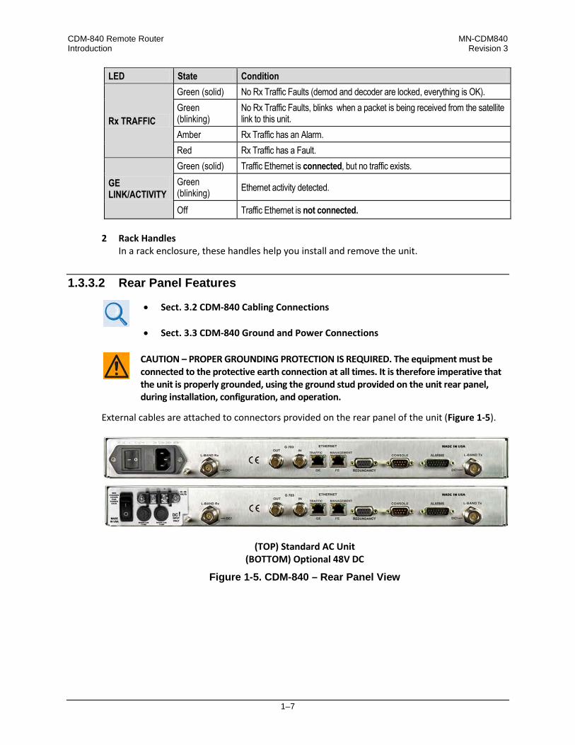
Rx TRAFFIC
Green (solid) No Rx Traffic Faults (demod and decoder are locked, everything is OK). Green (blinking)
No Rx Traffic Faults, blinks when a packet is being received from the satellite link to this unit.
Amber Rx Traffic has an Alarm. Red Rx Traffic has a Fault.
GE LINK/ACTIVITY
Green (solid) Traffic Ethernet is connected, but no traffic exists. Green (blinking) Ethernet activity detected.
Off Traffic Ethernet is not connected. 2 Rack Handles
In a rack enclosure, these handles help you install and remove the unit.
1.3.3.2 Rear Panel Features
• Sect. 3.2 CDM-840 Cabling Connections
• Sect. 3.3 CDM-840 Ground and Power Connections
CAUTION – PROPER GROUNDING PROTECTION IS REQUIRED. The equipment must be connected to the protective earth connection at all times. It is therefore imperative that the unit is properly grounded, using the ground stud provided on the unit rear panel, during installation, configuration, and operation.
External cables are attached to connectors provided on the rear panel of the unit (Figure 1-5).
(TOP) Standard AC Unit (BOTTOM) Optional 48V DC
Figure 1-5. CDM-840 – Rear Panel View

CDM-840 Remote Router MN-CDM840 Introduction Revision 3
1–8
1.3.3.2.1 Rear Panel Standard Features
As per Figure 1-5, from left to right: Power Interface: • 100V to 240V AC Primary Input Power Supply with Press-fit Fuse Holder IF Interfaces: • (2X) Type ‘N’ female L-BAND Rx (at far left) and L-Band Tx (at far right) connectors for 50Ω
L-Band (950 to 2150 MHz) Utility and Traffic Data Interfaces: • (1X) RJ-45 ETHERNET | TRAFFIC | GE 10/100/1000 BaseT Gigabit Ethernet port for Ethernet
traffic. • (1X) RJ-45 ETHERNET | MANAGEMENT | FE 10/100 BaseT Fast Ethernet port for Ethernet-
based management and control purposes (HTTP and SNMP). • (1X) DB-9M EIA-232 CONSOLE connector for serial remote control. • (1X) DB-15M EIA-232 ALARMS connector for I&Q Constellation/Rx AGC Monitor Output.
1.3.3.2.2 Rear Panel Optional Features
As per Figure 1-5, from left to right: Optional Power Interfaces: • -48V DC Primary Input Power Supply with Screw-in Fuse Holders • 24V DC BUC 90 Watt Power Supply (AC Input or DC Input versions) • 48V DC BUC 150 Watt Power Supply (AC Input or DC Input versions) Optional data interfaces • (2X) Type ‘BNC’ female connectors labeled “G.703 | IN / OUT” are provided for operation of
the optional G.703 E1 Interface/RAN Optimization FAST Feature upgrade.
Optional hardware operation: • (1X) DB-9F EIA-232 REDUNDANCY connector for interoperability with a separately
purchased Comtech EF Data CRS-170A 1:1 L-Band Redundancy Switch. Rear Panel Rack Support Brackets Kits are available from Comtech EF Data: • KT-0000168 4” Rear-Mounting Support Brackets Kit • KT-0000195 10” Rear-Mounting Support Brackets Kit
Sect. 2.2.1 Install the Optional Rear-Mounting Support Brackets Kit

CDM-840 Remote Router MN-CDM840 Introduction Revision 3
1–9
1.3.4 On-site Firmware Updates
Chapter 4. UPDATING FIRMWARE
Field update of the operating system firmware is possible through file upload via satellite or the Ethernet port.
1.3.5 On-site Operational Upgrades
Chapter 5. FAST ACTIVATION PROCEDURE
Field activation of software-based options is possible through Comtech EF Data’s FAST (Fully Accessible System Topology) Feature upgrade process.
1.3.6 Monitor and Control Interfaces
• Chapter 6. ETHERNET-BASED REMOTE PRODUCT MANAGEMENT • Chapter 7. SERIAL-BASED REMOTE PRODUCT MANAGEMENT
The unit is managed through multiple interfaces providing options for both in-band (over satellite) and out-of-band monitor and control (M&C).

CDM-840 Remote Router MN-CDM840 Introduction Revision 3
1–10
1.4 Specifications
1.4.1 Product Features
Item Description
Front Panel
8 Light-Emitting Diodes (LEDs): UNIT STATUS (Green/Amber/Red) STORED EVENT (Amber) ONLINE (Green) TEST MODE (Amber)
TRANSMITTER ON (Green/Red) Tx TRAFFIC (Green/Amber/Red) Rx TRAFFIC (Green/Amber/Red) GE LINK/ACTIVITY (Green)
Rear Panel IF Connectors / Impedance
Tx Type ‘N’ female connectors, 50Ω Rx
Rear Panel Data Interface Connectors
• 1X RJ-45 female port for 10/100/1000 BaseT Gigabit Ethernet data traffic • 1X RJ-45 female port for 10/100 BaseT Fast Ethernet HTTP and SNMP product
management • 1X DB-9M EIA-232 connector for serial remote monitor and control • 1X DB-9F EIA-232 connector for 1:1 or 1:N redundancy switch operation • 1X DB-15M connector for Form C unit alarms • 2X Type ‘BNC’ female connectors for optional G.703 E1, 2.048 Mbps (Unbalanced
75Ω)
Packet Processor Supported Protocols
RFC 768 – UDP RFC 791 – IP RFC 792 – ICMP RFC 793 – TCP RFC 826 – ARP RFC 856 – Telnet RFC 862 – Ping RFC 894 – IP
RFC 959 – FTP RFC 1112 – IP Multicast RFC 1213 – SNMP MIB II RFC 1812 – IPv4 Routers RFC 2045 – MIME RFC 2474 – DiffServ RFC 2475 – DiffServ RFC 2578 – SMI
RFC 2597 – AF PHB RFC 2598 – Expedite Forwarding RFC 2616 – HTTP RFC 3412 – SNMP RFC 3416 – SNMPv2 RFC 3418 – SNMP MIB
Packet Processor Statistics Detailed packet and throughput statistics
1.4.2 Physical, Power, and Environmental
Parameter Specifications
Physical Dimensions 1RU high x 19.0 inches wide x 16.1 inches deep (4.4 cm h x 48 cm w x 40.8 cm d) approximate
Weight 3.2 kg (7 lbs)
Power Supply AC 100V to 240V AC, 47 to 63 Hz, IEC 320 input DC (HW Option) -48V (36V to 60V) DC
Power Consumption 60 W typical
Fuse AC 120/230 V AC: T3.15A, Slo-Blo 20 mm DC (HW Option) -48V DC (38 to 60 V DC): T8.0A, Slo-Blo 20 mm
Temperature Operating 0° to 50°C (32° to 122°F) Storage -20° to 70°C (-4° to 158°F)
Humidity 95% maximum, non-condensing

CDM-840 Remote Router MN-CDM840 Introduction Revision 3
1–11
1.4.3 Modulator
Parameter Specifications Operating Frequency 950 to 2150 MHz L-Band, 100 Hz frequency resolution Frequency Reference ±0.06 ppm (±6 x 10⁻⁸), 0 to 50°C (32 to 122°F) Scrambling Comtech, disabled Spectral Inversion Normal or Inverted Transmit Filtering Per IESS-308/-309 spectral mask Transmit Filter Rolloff (Alpha) 20%, 25%, 35% Output Power 0 to -40 dBm, in 0.1 dB steps Power Accuracy ±1.0 dB over frequency, data rate, modulation type and temperature range of 0 to 50°C Transmit On/Off Ratio -60 dBc minimum
Harmonics and Spurious Better than -60 dBc/4 kHz (typically < -65 dBc/4KHz) Measured from Fo ±300 MHz
Output Phase Noise
<1º rms double sided, 100 Hz to 1MHz (minimum of 6 dB better overall than the Intelsat IESS-308/309 requirement)
dB/Hz Frequency -66.0 -76.0 -86.0 -96.0
100 Hz 1 kHz
10 kHz 100 kHz
Fundamental AC line spurious is -42 dBc or lower. The sum of all other single sideband spurious, from 0 to 0.75 x symbol rate, is -48 dBc or lower
Connector / Impedance Type ‘N’ female, 50Ω Return Loss 20 dB, minimum External Tx Carrier Off By TTL ‘low’ signal Test Modes CW, 1/0 pattern, 2^23-1 and 2047 patterns
1.4.3.1 Transmit
Return (Remote to Hub) Parameter Specifications Transmit Power 0 to -40 dBm Data Rate 16 kbps to 15.35 Mbps, in 1 bps step (CCM mode) (Modulation and FEC dependent) Symbol Rate 16 ksps – 4.5 Msps FEC Mode VersaFEC Encoder (ACM and CCM modes)
Modulation and Code Rates
• BPSK 0.488 (16.00 kbps – 2.19 Mbps) • QPSK 0.533 (17.07 kbps – 4.80 Mbps) • QPSK 0.631 (20.19 kbps – 5.67 Mbps) • QPSK 0.706 (22.577 kbps – 6.34 Mbps) • QPSK 0.803 (25.69 kbps – 7.22 Mbps) • 8-QAM 0.642 (30.83 kbps – 8.67 Mbps) • 8-QAM 0.711 (34.14 kbps – 9.60 Mbps) • 8-QAM 0.780 (37.44 kbps – 10.53 Mbps) • 16-QAM 0.731 (46.80 kbps – 13.26 Mbps) • 16-QAM 0.780 (49.92 kbps – 14.04 Mbps) • 16-QAM 0.829 (53.04 kbps – 14.91 Mbps) • 16-QAM 0.853 (54.60 kbps – 15.35 Mbps)
Encapsulation Ultra-low overhead Streamline Encapsulation

CDM-840 Remote Router MN-CDM840 Introduction Revision 3
1–12
1.4.3.2 Block Up Converter (BUC) Support
Parameter Specifications
Reference (10 MHz) Supplied through Tx IF center conductor, 10.0 MHz ±0.06 ppm, selectable on/off, 0.0 dBm ±3 dB
Power Supply (HW Option)
Supplied through Tx IF center conductor and selectable on/off via M&C control • 24V DC, 4.17 Amps max., 90W @ 50° C • 48V DC, 3.125 Amps max., 150W @ 50° C
1.4.4 Demodulator
Parameter Specifications Operating Frequency 950 to 2150 MHz L-Band, 100 Hz frequency resolution Connector / Impedance Type ‘N’ female, 50Ω Input Power Range, Desired Carrier -65 dBm + 10log(symbol rate in MHz) to -25 dBm
Maximum Composite Operating Level
-5 dBm total composite power • 20 dBc within 10 MHz band from the desired carrier for QPSK, 8-PSK, and 16-APSK • 10 dBc within 10 MHz band from the desired carrier for 32-APSK • 30 dBc outside of 10 MHz from carrier
Absolute Maximum, No Damage -10 dBm
Receive Filter Rolloff (Alpha) 20%, 25%, 35% Acquisition Range ±100 kHz Adaptive Equalizer 5-tap, selectable, corrects up to 3 dB tilt Return Loss 12 dB, minimum (typical 15 dB) Monitor Functions Es/No estimate, receive signal level, frequency offset Monitor Accuracy
Es/No ±0.3 dB Rx Signal Level ±6 dB (typical)
1.4.4.1 Receive
Outbound (Hub to Remote) Parameter
Specifications
Data Rate (Pilots On)
• QPSK 0.479 – 108.255 Mbps • 8-PSK 1.740 – 160.0 Mbps • 16-APSK 2.575 – 160.0 Mbps • 32-APSK 3.623 – 160.0 Mbps
Symbol Rate
• QPSK 1 to 62 Msps • 8-PSK 1 to 62 Msps • 16-APSK 1 to 47 Msps • 32-APSK 1 to 37 Msps
FEC DVB-S2 Decoder (ACM, CCM, and VCM modes), Short Frame, Normal frame

CDM-840 Remote Router MN-CDM840 Introduction Revision 3
1–13
Outbound (Hub to Remote) Parameter
Specifications
Demodulation / FEC / Data Rate Ranges (Normal FEC Frame, Pilots On)
• QPSK 1/4 0.479 – 29.672 Mbps • QPSK 1/3 0.641 – 39.731Mbps • QPSK 2/5 0.771 – 47.779 Mbps • QPSK 1/2 0.965 – 59.850 Mbps • QPSK 3/5 1.160 – 71.922 Mbps • QPSK 2/3 1.291 – 80.029 Mbps • QPSK 3/4 1.452 – 90.029 Mbps • QPSK 4/5 1.549 – 96.064 Mbps • QPSK 5/6 1.615 – 100.148 Mbps • QPSK 8/9 1.724 – 106.914 Mbps • QPSK 9/10 1.749 – 108.255 Mbps • 8-PSK 3/5 1.740 – 107.853 Mbps • 8-PSK 2/3 1.936 – 120.011 Mbps • 8-PSK 3/4 2.178 – 135.007 Mbps
• 8-PSK 5/6 2.422 – 150.181 Mbps • 8-PSK 8/9 2.586 – 160.000 Mbps • 8-PSK 9/10 2.618 – 160.000 Mbps • 16-APSK 2.575 – 121.007 Mbps • 16-APSK 2.896 – 136.217 Mbps • 16-APSK 3.090 – 145.253 Mbps • 16-APSK 3.222 – 151.428 Mbps • 16-APSK 3.440 – 160.000 Mbps • 16-APSK 3.483 – 160.000 Mbps • 32-APSK 3.623 – 134.063 Mbps • 32-APSK 3.866 – 143.051 Mbps • 32-APSK 4.031 – 149.132 Mbps • 32-APSK 4.303 – 159.207 Mbps • 32-APSK 4.357 – 160.000 Mbps
Pilots On Decapsulation Low-Overhead Enhanced GSE
1.4.4.2 Low Noise Block Down Converter (LNB) Support
Parameter Specifications
Reference (10 MHz) Supplied through Rx IF center conductor, 10.0 MHz ±0.06 ppm, Selectable ON/OFF, -3.0 dBm ±3 dB
Voltage Selectable ON/OFF, 13V DC, 18V DC, 24V DC Current 500 mA, maximum

CDM-840 Remote Router MN-CDM840 Introduction Revision 3
1–14
1.4.5 BER (Bit Error Rate)
VersaFEC CODEC BER BPSK (With two adjacent carriers, each 7 dB higher than the desired carrier)
For BER=10-x Rate – Guaranteed Eb/No (typical value in parentheses) BER=10-5 BER=10-8
Rate 0.488 2.4 dB (2.1 dB) 2.7 dB (2.4 dB)
VersaFEC CODEC BER QPSK (With two adjacent carriers, each 7 dB higher than the desired carrier)
BER=10-5 BER=10-8
Rate 0.533 QPSK 2.3 dB (2.0 dB) 2.5 dB (2.2 dB)
Rate 0.631 QPSK 2.8 dB (2.5 dB) 3.0 dB (2.7 dB)
Rate 0.706 QPSK 3.3 dB (3.0 dB) 3.7 dB (3.4 dB)
Rate 0.803 QPSK 3.8 dB (3.5 dB) 4.1 dB (3.8 dB)
VersaFEC CODEC BER 8QAM (With two adjacent carriers, each 7 dB higher than the desired carrier)
BER=10-5 BER=10-8
Rate 0.642 8QAM 4.6 dB (4.3 dB) 4.9 dB (4.6 dB)
Rate 0.711 8QAM 5.2 dB (4.9 dB) 5.5 dB (5.2 dB)
Rate 0.780 8QAM 5.6 dB (5.3 dB) 6.0 dB (5.7 dB)
VersaFEC CODEC BER 16QAM (With two adjacent carriers, each 7 dB higher than the desired carrier)
BER=10-5 BER=10-8
Rate 0.731 16QAM 6.4 dB (6.1 dB) 6.6 dB (6.3 dB)
Rate 0.780 16QAM 7.0 dB (6.7 dB) 7.3 dB (7.0 dB)
Rate 0.829 16QAM 7.5 dB (7.2 dB) 7.8 dB (7.5 dB)
Rate 0.853 16QAM 8.0 dB (7.7 dB) 8.3 dB (8.0 dB)
1.4.5.1 BER Monitor Functions
Parameter Specifications Eb/No Estimate 3 to 12 dB with ± 0.5 dB accuracy Corrected Bit Error Rate 1E-3 to 1E-9 Frequency Offset ±32 kHz range,100 Hz resolution Signal Strength Indicator 0 to 60 dB range relative to maximum gain
1.4.6 Regulatory Compliance
Entity Description
“CE” as follows:
• EN 30489-1 • EN 55022 Class B (Emissions) • EN 55024 (Immunity) • EN 60950 (Safety)
FCC FCC Part 15 Subpart B
RoHS Compliance Yes

2–1
Chapter 2. INSTALLATION
2.1 Unpack and Inspect the Shipment
Figure 2-1. Unpack and Inspect the Shipment
The CDM-840 Remote Router, its optional Installation and Operation Manual (otherwise available online at http://www.comtechefdata.com), and its power cord were packaged and shipped in a reusable cardboard carton containing protective foam spacing.
CAUTION – THIS EQUIPMENT CONTAINS PARTS AND ASSEMBLIES SENSITIVE TO DAMAGE BY ELECTROSTATIC DISCHARGE (ESD). USE ESD PRECAUTIONARY PROCEDURES WHEN HANDLING THE EQUIPMENT.

CDM-840 Remote Router MN-CDM840 Installation Revision 3
2–2
Once opened, inspect the shipment:
Step Task
1 Keep all shipping materials.
2 Check the packing list to make sure the shipment is complete.
3 Inspect the equipment for damage. If damage exists, immediately contact the carrier and Comtech EF Data to submit a damage report.
4 Read the manual.
2.2 Install the Unit Into a Rack Enclosure
Install the CDM-840 in its assigned position in the rack enclosure (Figure 2-2). Use, as required: • A standard rack-mounted shelf;
• User-supplied screws to secure the front panel to the rack enclosure threaded front
mounting rails;
• Comtech EF Data’s optional KT-0000168 (4”) or KT-0000195 (10”) Rear Support Brackets Kit (Figure 2-3).
For information about custom rack enclosures, contact Comtech EF Data Product Support. CAUTION – CONNECT THE GROUND STUD, LOCATED ON THE REAR PANEL OF THE
UNIT, TO A POWER SYSTEM THAT HAS SEPARATE GROUND, LINE AND NEUTRAL CONDUCTORS. DO NOT CONNECT THE UNIT WITHOUT A DIRECT CONNECTION TO GROUND. SUFFICIENT AIR VENTILATION IS REQUIRED. Make sure there is adequate air ventilation clearance inside the enclosure, especially at the side. In a rack system where there is high heat discharge, provide forced-air cooling with top- or bottom-mounted fans or blowers. The CDM-840 CANNOT have rack slides mounted to the sides of the chassis. Cooling fans and exhaust vents are provided here – air flow must not be impeded. Comtech EF Data recommends that an alternate method of support is provided within the rack, such as standard rack shelves or the optional Rear-Mounting Support Brackets Kit. If there is any doubt, contact Comtech EF Data Customer Support during normal business hours. MAXIMUM AIR TEMPERATURE. Make sure the air temperature inside the enclosure never exceeds 50°C (122°F).

CDM-840 Remote Router MN-CDM840 Installation Revision 3
2–3
Feature Description
1 Custom Rack Enclosure 2 CDM-840 Unit 3 Standard Rack Shelving 4 Rack Enclosure Threaded Front Rail (typical) 5 Unit Front Panel 6 User-supplied Screws
Figure 2-2. Install the Unit Into a Rack Enclosure
2.2.1 Install the Optional Rear Support Brackets Kit

CDM-840 Remote Router MN-CDM840 Installation Revision 3
2–4
Feature Description 1 Back of Unit 2 Rack Enclosure Threaded Rear Mounting Rail (typical)
KT-0000XXX Primary Rear Support Brackets Kit
Item Quantity
CEFD Part Number Description KT-0000168 KT-0000195
1 2 2 FP-0000913 Plate, Adapter 2 4 4 HW/10-32X3/8FLT Screw, #10 Flat Head
3 1 – KT/6228-2 4” Rear Support Bracket Kit – 1 KT/6228-3 10” Rear Support Bracket Kit
KT/6228-X Rear Support Bracket Kit
Item Quantity
CEFD Part Number Description KT/6228-2 KT/6228-3
A 2 2 HW/10-32SHLDR Screw, #10 Shoulder B 4 4 HW/10-32FLT Washer, #10 Flat C 2 2 HW/10-32SPLIT Washer, #10 Split D 2 2 HW/10-32HEXNUT Nut, #10 Hex E 4 4 HW/10-32x1/2RK Bolt, #10 Rack Bracket
F 2 – FP/6138-2 Bracket, Rear Support – 4” – 2 FP/6138-3 Bracket, Rear Support – 10”
Figure 2-3. Install the Optional Rear Support Brackets Kit Tools needed to install the optional KT-0000168 (4”) or KT-0000195 (10”) Brackets Kit:

CDM-840 Remote Router MN-CDM840 Installation Revision 3
2–5
• A medium Phillips screwdriver
• A 5/32-inch SAE Allen Wrench
• An adjustable Crescent wrench. Do these steps to install the brackets kit (Figure 2-3):
Step Description
1 Assemble the Adapter Plates to the back sides of the CDM-840 chassis using the #10 Flat Head Screws.
2 Assemble the #10 Shoulder Screws through the Adapter Plate mounting slots using the #10 Flat Washers, #10 Split Washers, and #10 Hex Nuts.
3 Mount the Rear Support Brackets to the rack enclosure threaded rear mounting rails using the #10 Rack Bracket Bolts.
4 Slide the CDM-840 into the front of the rack enclosure. Make sure that the #10 Shoulder Screws properly engage into the slots of the Rear Support Brackets.

CDM-840 Remote Router MN-CDM840 Installation Revision 3
2–6
Notes:

3–1
Chapter 3. REAR PANEL CONNECTIONS
3.1 Overview – Cabling Connection Types
Comtech EF Data’s Advanced VSAT Series group of products, including the CDM-840 Remote Router, use a number of different cables. Each cable type is typically dedicated to a specific mode of operation.
1) Not all of these operational interface types may be available.
2) The European EMC Directive (EN55022, EN50082-1) requires using properly shielded cables for DATA I/O. These cables must be double-shielded from end-to-end, ensuring a continuous ground shield.

CDM-840 Remote Router MN-CDM840 Rear Panel Connections Revision 3
3–2
3.1.1 Coaxial Cable Connections
Coupling Type Connector Type
Plug Jack
Bayonet (Type ‘BNC’ shown)
Threaded (Type ‘N’ shown)
Figure 3-1. Coaxial Connector Examples The types of coaxial cables used by Comtech EF Data are ‘BNC’, ‘TNC’, ‘N’, ‘F’, and ‘SMA’. Coaxial cables (plugs) and their mating connectors (jacks/sockets) are available in two coupling styles: Bayonet or Threaded: • Bayonet Coupling Style: The jack has a pair of guide posts that accommodate the plug’s
lockdown slots. This lockdown design provides secure assembly without over-tightening the connection.
• Threaded Coupling Style: The jack features external threads. The plug shell features internal threads, and has either a knurled outer surface to permit hand-tightening of the connection, or hex flats to accommodate torqued installation.
Connection Instructions: • Bayonet Coupling Connections: Use the plug slots to guide, then slide the plug onto the jack
posts. Then, turn the plug clockwise until the jack posts are fully seated within the plug slot.
• Threaded Coupling Connections: Engage the plug onto the jack threads, and then turn the plug clockwise until it is fully threaded onto the jack. Do not over-tighten the connection.
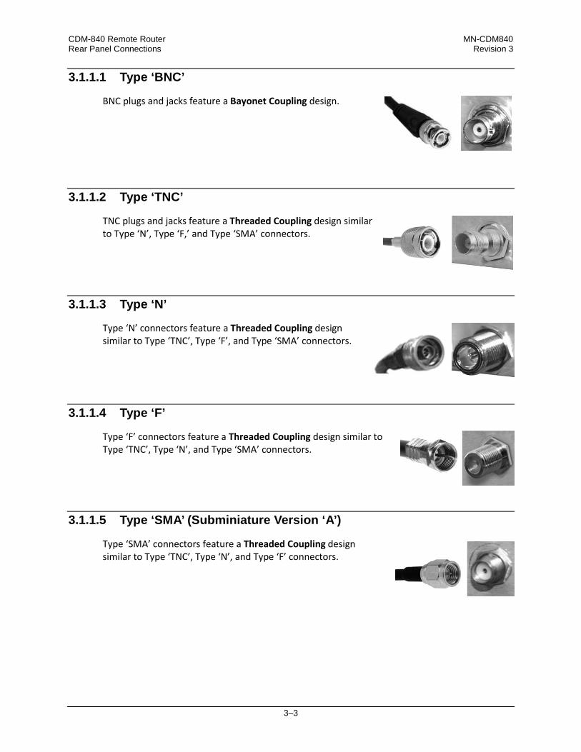
CDM-840 Remote Router MN-CDM840 Rear Panel Connections Revision 3
3–3
3.1.1.1 Type ‘BNC’
BNC plugs and jacks feature a Bayonet Coupling design.
3.1.1.2 Type ‘TNC’
TNC plugs and jacks feature a Threaded Coupling design similar to Type ‘N’, Type ‘F,’ and Type ‘SMA’ connectors.
3.1.1.3 Type ‘N’
Type ‘N’ connectors feature a Threaded Coupling design similar to Type ‘TNC’, Type ‘F’, and Type ‘SMA’ connectors.
3.1.1.4 Type ‘F’
Type ‘F’ connectors feature a Threaded Coupling design similar to Type ‘TNC’, Type ‘N’, and Type ‘SMA’ connectors.
3.1.1.5 Type ‘SMA’ (Subminiature Version ‘A’)
Type ‘SMA’ connectors feature a Threaded Coupling design similar to Type ‘TNC’, Type ‘N’, and Type ‘F’ connectors.

CDM-840 Remote Router MN-CDM840 Rear Panel Connections Revision 3
3–4
3.1.2 D-Subminiature Cable Connections
Type ‘D’ Connection Type Example
Chassis Receptacles: Female (top)
Male (bottom)
Type ‘D’ Cable with Jack Screws (female shown)
Figure 3-2. D-Subminiature Connector Examples D-Subminiature connectors are also called Type ‘D’ or ‘D-Sub’ connectors. The connector pair features multiple rows of pins (male side) coupled to mating sockets (female side). The cable plug and chassis receptacle each feature a D-shaped profile that interlock to ensure proper pin orientation and connector seating. Either chassis receptacle gender features two jack nuts for secure assembly of the cable plug to the chassis receptacle. Whether its gender is male or female, the cable plug features two jack screws for secure connection to the jack nuts provided on the mating chassis receptacle. The jack screws may be hand tightened or tightened with a standard flat-blade screwdriver. Connection Instructions: Orient the plug to the receptacle in the proper position. Press firmly into place. Use the jack screws to secure the plug to the receptacle jack nuts. Do not over-tighten. About connector pinout tables: Figure 3-2 identifies the Pin 1 location for either gender connector. Unless noted otherwise, the connector pinout tables provided in this manual arrange/order information (i.e., the Pin # column/row) based on this orientation.
3.1.3 RJ-45, RJ-48 Cable Connections
The plug for an RJ-45 or RJ-48 cable features a flexible tab. The RJ-45 or RJ-48 jack features a mating slot. This design configuration assures proper installation and pin orientation. Connection Instructions: Press down the tab on the cable plug, and then insert the plug into the RJ-4x jack. The connection is complete when the tab ‘clicks’ into position inside the jack.

CDM-840 Remote Router MN-CDM840 Rear Panel Connections Revision 3
3–5
3.2 CDM-840 Cabling Connections
The CDM-840 rear panel connectors, shown here in Figure 3-3 provide all necessary external connections between the unit and other equipment.
(TOP) Standard AC Unit
(BOTTOM) Optional -48V DC Unit
Figure 3-3. CDM-840 Cabling Connections Table 3-1 summarizes the available connectors, grouped according to service function.
Table 3-1. CDM-840 Rear Panel Connectors
Conn. Group
Group Name (Chapter Sect.) Connector Name Connector Type Connector Function
1 IF Connector Group (3.2.1)
L-BAND Rx 50Ω Type ‘N’ female L-Band Input
L-BAND Tx 50Ω Type ‘N’ female L-Band Output
2 Terrestrial Data
Connector Group (3.2.2)
G.703 OUT BNC female G.703 E1 Output
IN BNC female G.703 E1 Input ETHERNET | TRAFFIC | GE RJ-45 female 10/100/1000 BaseT Gigabit Ethernet
interface (IEEE 802.3ab)
3 Utility Connector Group (3.2.3)
ETHERNET | MANAGEMENT | FE RJ-45 female
10/100 BaseT Fast Ethernet management/data interface (IEEE 802.3u)
REDUNDANCY 9-pin Type ‘D’ female For connection to an optional 1:1 or 1”N CEFD Redundancy Switch
CONSOLE 9-pin Type ‘D’ male EIA-232 Serial Remote Interface
ALARMS 15-pin Type ‘D’ male Unit Alarms
See Sect. 3.1 Overview – Cabling Connections Types for information about each connector type and its connection instructions.
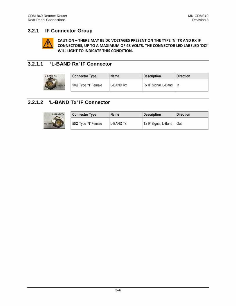
CDM-840 Remote Router MN-CDM840 Rear Panel Connections Revision 3
3–6
3.2.1 IF Connector Group
CAUTION – THERE MAY BE DC VOLTAGES PRESENT ON THE TYPE ‘N’ TX AND RX IF CONNECTORS, UP TO A MAXIMUM OF 48 VOLTS. THE CONNECTOR LED LABELED ‘DC!’ WILL LIGHT TO INDICATE THIS CONDITION.
3.2.1.1 ‘L-BAND Rx’ IF Connector
3.2.1.2 ‘L-BAND Tx’ IF Connector
Connector Type Name Description Direction
50Ω Type ‘N’ Female L-BAND Rx Rx IF Signal, L-Band In
Connector Type Name Description Direction
50Ω Type ‘N’ Female L-BAND Tx Tx IF Signal, L-Band Out
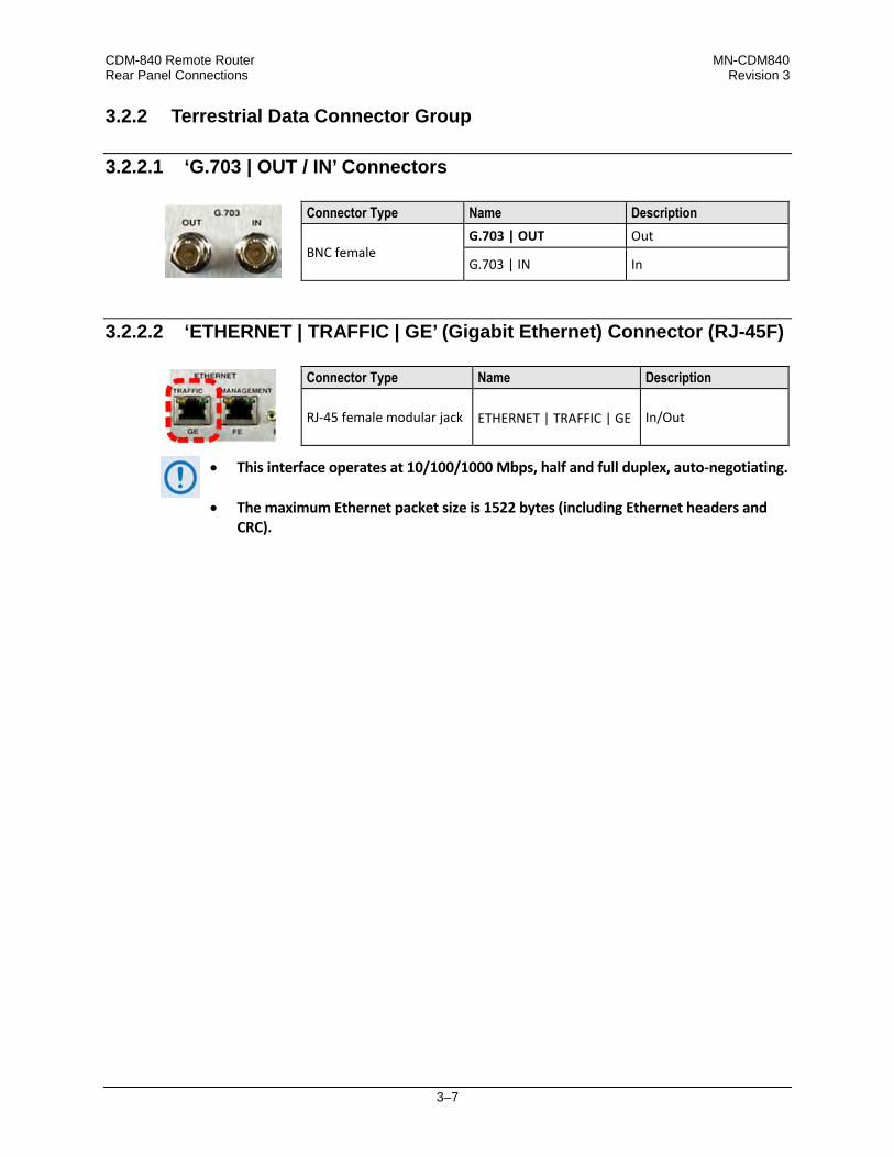
CDM-840 Remote Router MN-CDM840 Rear Panel Connections Revision 3
3–7
3.2.2 Terrestrial Data Connector Group
3.2.2.1 ‘G.703 | OUT / IN’ Connectors
3.2.2.2 ‘ETHERNET | TRAFFIC | GE’ (Gigabit Ethernet) Connector (RJ-45F)
• This interface operates at 10/100/1000 Mbps, half and full duplex, auto-negotiating.
• The maximum Ethernet packet size is 1522 bytes (including Ethernet headers and CRC).
Connector Type Name Description
BNC female G.703 | OUT Out
G.703 | IN In
Connector Type Name Description
RJ-45 female modular jack ETHERNET | TRAFFIC | GE In/Out

CDM-840 Remote Router MN-CDM840 Rear Panel Connections Revision 3
3–8
3.2.3 Utility Connector Group
3.2.3.1 ‘ETHERNET | MANAGEMENT | FE’ (Fast Ethernet) Connector (RJ-45F)
• This interface operates at 10/100 Mbps, half and full duplex, auto-negotiating.
• The maximum Ethernet packet size is 1522 bytes (including Ethernet headers and CRC).
3.2.3.2 ‘REDUNDANCY’ Interface Connector (DB-9F) (FUTURE)
Use this interface for future connection to an optional CEFD CRS-170A 1:1 L-Band Redundancy Switch.
Table 3-2. ‘REDUNDANCY’ Connector Pinouts
Pin # Description Direction 5 Ground –
9 Fused +12 volt Out 4 Redundancy In 2 In
8 Redundancy Out 2 Out 3 Redundancy In 1 In
7 Redundancy Out 1 Out 2 Receive Serial Data – auxiliary channel In
6 Transmit Serial Data – auxiliary channel Out 1 Ground –
Connector Type Name Description
RJ-45 female modular jack ETHERNET | TRAFFIC | FE In/Out
Connector Type Name Description
Type ‘D’ 9-pin female REDUNDANCY In/Out

CDM-840 Remote Router MN-CDM840 Rear Panel Connections Revision 3
3–9
3.2.3.3 ‘CONSOLE’ Interface Connector (DB-9M)
Use this interface for EIA-232 communications. It is intended for connection to an M&C computer or VT (Video Terminal) device.
Table 3-3. ‘CONSOLE’ Connector Pinouts
Pin # Description Direction
1 Ground –
6 Reserved - do not connect to this pin –
2 EIA-232 Transmit Data Out
7 Reserved - do not connect to this pin –
3 EIA-232 Receive Data In
8 Reserved - do not connect to this pin –
4 Reserved - do not connect to this pin –
9 Reserved - do not connect to this pin –
5 Ground –
Connector Type Name Description
Type ‘D’ 9-pin male CONSOLE In/Out

CDM-840 Remote Router MN-CDM840 Rear Panel Connections Revision 3
3–10
3.2.3.4 ‘ALARMS’ Interface Connector (DB-15M)
Pin 2 of this connector provides an analog signal to aid antenna pointing or for driving step-track equipment. The analog signal will be zero volts when the unit is not locked to a carrier. When locked to a carrier the analog signal will be 1 volt for Es/No values less than or equal to -4.69 dB, or 10 volts for Es/No values greater than or equal to 20dB as depicted in the following chart:
Table 3-4. ‘ALARMS’ Connector Pinouts
PIN # SIGNAL FUNCTION NAME 1 GROUND GND
9 EXT CARRIER OFF EXT-OFF 2 ES/NO VOLTAGE (0 TO 10 VOLTS) ES/NO
10 RESERVED +3.3V INPUT CMOS LEVEL N/C 3 NO CONNECTION N/C
11 NO CONNECTION N/C 4 UNIT FAULT UNIT-COM
12 UNIT FAULT (ENERGIZED, NO FAULT) UNIT-NO 5 UNIT FAULT (DE-ENERGIZED, FAULTED) UNIT-NC
13 TX TRAFFIC TX-COM 6 TX TRAFFIC (ENERGIZED, NO FAULT) TX-NO
14 TX TRAFFIC (DE-ENERGIZED, FAULTED) TX-NC 7 RX TRAFFIC RX-COM
15 RX TRAFFIC (ENERGIZED, NO FAULT) RX-NO 8 RX TRAFFIC (DE-ENERGIZED, FAULTED) RX-NC
Connector Type Name Description
Type ‘D’ 15-pin male ALARMS In/Out
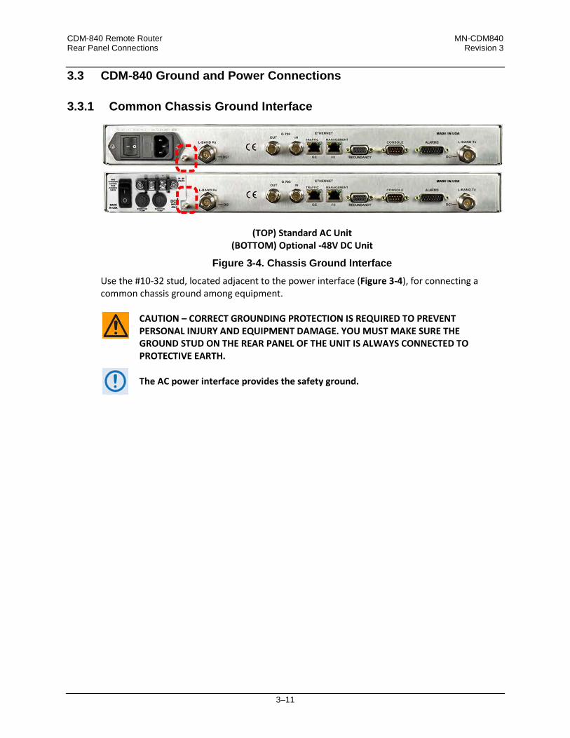
CDM-840 Remote Router MN-CDM840 Rear Panel Connections Revision 3
3–11
3.3 CDM-840 Ground and Power Connections
3.3.1 Common Chassis Ground Interface
(TOP) Standard AC Unit (BOTTOM) Optional -48V DC Unit
Figure 3-4. Chassis Ground Interface Use the #10-32 stud, located adjacent to the power interface (Figure 3-4), for connecting a common chassis ground among equipment.
CAUTION – CORRECT GROUNDING PROTECTION IS REQUIRED TO PREVENT PERSONAL INJURY AND EQUIPMENT DAMAGE. YOU MUST MAKE SURE THE GROUND STUD ON THE REAR PANEL OF THE UNIT IS ALWAYS CONNECTED TO PROTECTIVE EARTH.
The AC power interface provides the safety ground.

CDM-840 Remote Router MN-CDM840 Rear Panel Connections Revision 3
3–12
3.3.2 115V/230V Alternating Current (AC) Power Interface (Standard)
Feature Description 1 On / Off Switch 2 Press-fit Fuse Holder 3 IEC Three-prong Connector
AC Power Specifications
Input Power 40W maximum, 20W typical (without BUC) 245W maximum (with BUC)
Input Voltage 100V to 240V AC, +6%/-10%, autosensing (total absolute max. range is 90 to 254V AC)
Connector Type IEC-60320 Type C13/C14
Fuse Protection
Line and neutral fusing (2X) 5mm x 20mm Slow-blow type fuses: • T2.5A (2.5A)(115V or 230V AC operation
without BUC) • T4A (4.0A)(115V or 230V AC operation
with BUC)
Figure 3-5. AC Power Interface
3.3.2.1 AC Operation – Apply Power
Figure 3-6. Apply AC Power to the Unit
Do these steps to apply AC power to the unit (Figure 3-6):
Step Task
1 Plug the provided AC power cord female end into the unit.
2 Plug the AC power cord male end into the user-supplied power source.
3 Switch the unit ON.
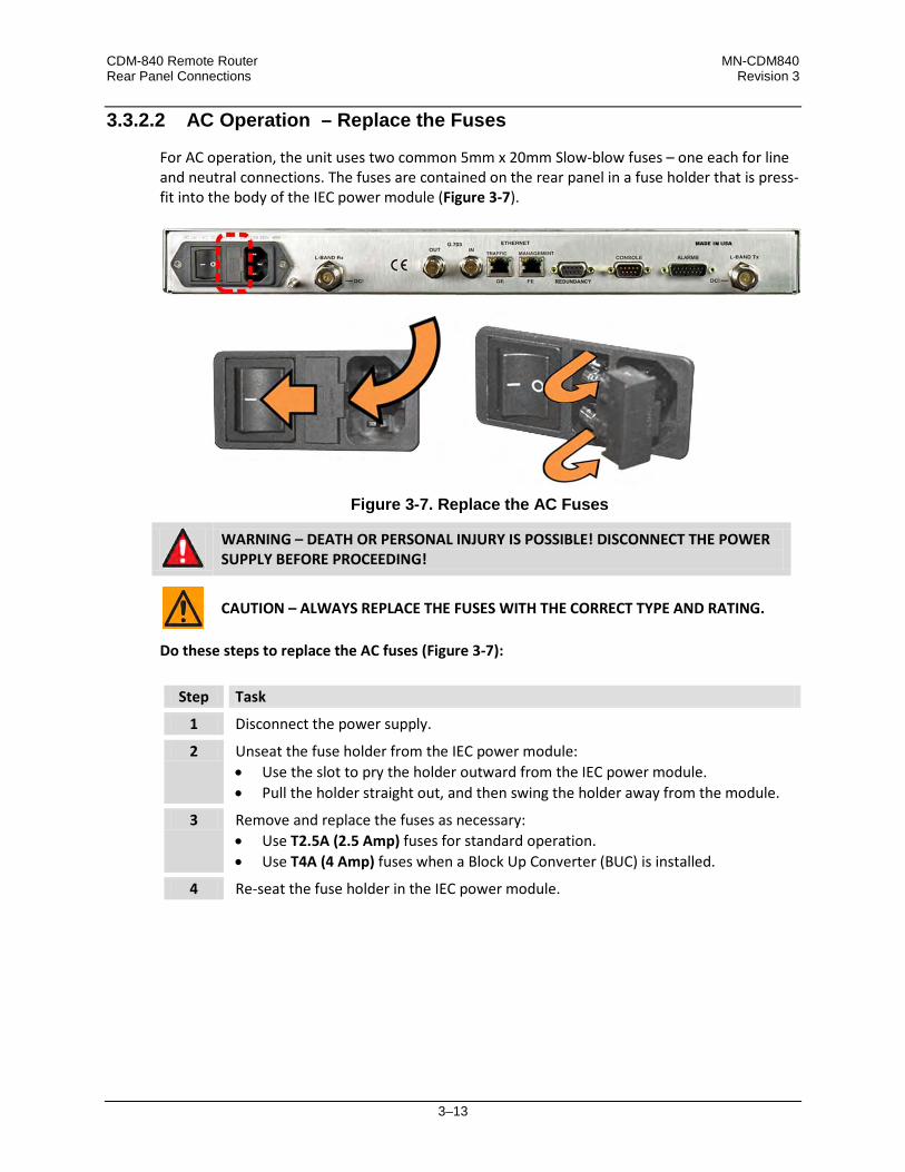
CDM-840 Remote Router MN-CDM840 Rear Panel Connections Revision 3
3–13
3.3.2.2 AC Operation – Replace the Fuses
For AC operation, the unit uses two common 5mm x 20mm Slow-blow fuses – one each for line and neutral connections. The fuses are contained on the rear panel in a fuse holder that is press-fit into the body of the IEC power module (Figure 3-7).
Figure 3-7. Replace the AC Fuses
WARNING – DEATH OR PERSONAL INJURY IS POSSIBLE! DISCONNECT THE POWER SUPPLY BEFORE PROCEEDING!
CAUTION – ALWAYS REPLACE THE FUSES WITH THE CORRECT TYPE AND RATING.
Do these steps to replace the AC fuses (Figure 3-7):
Step Task
1 Disconnect the power supply.
2 Unseat the fuse holder from the IEC power module: • Use the slot to pry the holder outward from the IEC power module. • Pull the holder straight out, and then swing the holder away from the module.
3 Remove and replace the fuses as necessary: • Use T2.5A (2.5 Amp) fuses for standard operation. • Use T4A (4 Amp) fuses when a Block Up Converter (BUC) is installed.
4 Re-seat the fuse holder in the IEC power module.

CDM-840 Remote Router MN-CDM840 Rear Panel Connections Revision 3
3–14
3.3.3 -48V Direct Current (DC) Power Interface (Optional)
Figure 3-8. DC Power Interface
3.3.3.1 DC Operation – Apply Power
Figure 3-9. Apply DC Power to the Unit
Do these steps to apply DC power to the unit (Figure 3-9):
Step Task
1 Connect the user-supplied (+) and (–) DC power leads to their respective terminals. Number 18 AWG minimum wires are recommended.
2 Connect the user-supplied DC power leads to the user power source.
3 Switch the unit ON.
Feature Description 1 On / Off Switch 2 Screw-in Fuse Holders / Receptacles 3 Power Terminal Block
DC Power Specifications
Input Power 25W (typical) 245W (maximum with BUC)
Input Voltage 48V DC, nominal (36V to 60V)
Connector Type Terminal Block
Fuse Protection
(2X) 5mm x 20mm Slow-blow type fuses: • T3A (3.0A) Main • T5A (5.0A) (BUC)

CDM-840 Remote Router MN-CDM840 Rear Panel Connections Revision 3
3–15
3.3.3.2 DC Operation – Replace the Fuses
For DC operation, the unit requires two different fuses. The fuses are located on the rear panel in the individual screw-in receptacles found below the terminal block (Figure 3-10).
Figure 3-10. Replace the DC Fuses
WARNING – DEATH OR PERSONAL INJURY IS POSSIBLE! DISCONNECT THE POWER SUPPLY BEFORE PROCEEDING!
CAUTION – ALWAYS REPLACE THE FUSES WITH THE CORRECT TYPE AND RATING.
Do these steps to replace the DC fuses (Figure 3-10):
Step Task
1 Disconnect the power supply.
2 Unscrew either fuse holder from its receptacle.
3 Remove and replace the fuse(s): • Use T3A (3 Amp) fuses for standard operation • Use T5A (5 Amp) fuses when a Block Up Converter (BUC) is installed.
4 Screw either fuse holder into its receptacle.

CDM-840 Remote Router MN-CDM840 Rear Panel Connections Revision 3
3–16
Notes:

4–1
Chapter 4. UPDATING FIRMWARE
4.1 Firmware Update Overview
Make sure to operate the CDM-840 with its latest available firmware.
The CDM-840 Remote Router is factory-shipped with the latest version of operating firmware. If you require a firmware update, you must contact Comtech EF Data Product Support. Firmware updates may be applied to an in-service CDM-840 without having to remove the covers of the unit chassis. Use the CDM-840 to update the firmware: • Obtain the firmware update archive file from Comtech EF Data Product Support.
• Establish the proper communications link for acquiring the firmware update archive files by
directly connecting a user-supplied Microsoft Windows-based PC to the ‘ETHERNET | MANAGEMENT | FE’ 10/100 Fast Ethernet port and the 9-pin serial ‘CONSOLE’ port located on the CDM-840 rear panel.
• Use Windows Command-line to transfer, via File Transfer Protocol (FTP), the extracted firmware files from the User PC to the CDM-840 standby firmware image.
• Use the CDM-840 HTTP (Web Server) Interface to configure the modem to operate using the updated firmware image.

CDM-840 Remote Router MN-CDM840 Updating Firmware Revision 3
4–2
(LEFT) Standard 115V/230V AC Unit (RIGHT) Optional -48V DC Unit
4.2 Getting Started: Prepare for the Firmware Download
Do these steps: 1. Identify the firmware number/revision letter/version number and the assigned Ethernet
Management IP Address. User-supplied items needed: • A Microsoft Windows-based PC, equipped with available serial and Ethernet ports; a
compatible Web browser (e.g., Internet Explorer); and a terminal emulator program (e.g., Tera Term or HyperTerminal).
• A CAT5 Ethernet cable to connect the PC Ethernet Port to the CDM-840. • A 9-pin serial cable to connect the PC serial port to the CDM-840. a) Use an Ethernet hub, switch, or direct
cable connection to connect the CDM-840 rear panel ‘ETHERNET | MANAGEMENT | FE’ 10/100 Fast Ethernet port to an Ethernet port on the User PC.
b) Use the 9-pin serial cable to connect the
CDM-850 rear panel ‘CONSOLE’ port to a serial port on the User PC.
c) On the PC – Open the terminal emulator program. Configure the program serial port communication and terminal display settings.
d) On the PC – Open the terminal emulator program.
Refer to your terminal emulator program HELP feature or user guide for operating and configuration instructions.
Configure the utility program serial port communication and terminal display operation: • 38400 bps (Baud Rate) • 8 Data Bits • 1 Stop Bit
• Parity = NO • Port Flow Control = NONE • Display New line Rx/Tx: CR
• Local Echo = ON
e) On the CDM-840: Turn on the power.
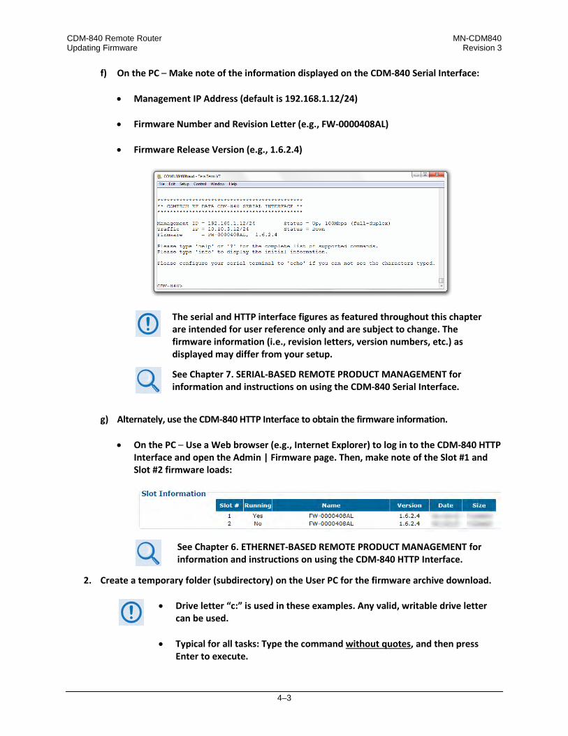
CDM-840 Remote Router MN-CDM840 Updating Firmware Revision 3
4–3
f) On the PC – Make note of the information displayed on the CDM-840 Serial Interface: • Management IP Address (default is 192.168.1.12/24)
• Firmware Number and Revision Letter (e.g., FW-0000408AL)
• Firmware Release Version (e.g., 1.6.2.4)
The serial and HTTP interface figures as featured throughout this chapter are intended for user reference only and are subject to change. The firmware information (i.e., revision letters, version numbers, etc.) as displayed may differ from your setup.
See Chapter 7. SERIAL-BASED REMOTE PRODUCT MANAGEMENT for information and instructions on using the CDM-840 Serial Interface.
g) Alternately, use the CDM-840 HTTP Interface to obtain the firmware information.
• On the PC – Use a Web browser (e.g., Internet Explorer) to log in to the CDM-840 HTTP
Interface and open the Admin | Firmware page. Then, make note of the Slot #1 and Slot #2 firmware loads:
See Chapter 6. ETHERNET-BASED REMOTE PRODUCT MANAGEMENT for information and instructions on using the CDM-840 HTTP Interface.
2. Create a temporary folder (subdirectory) on the User PC for the firmware archive download.
• Drive letter “c:” is used in these examples. Any valid, writable drive letter can be used.
• Typical for all tasks: Type the command without quotes, and then press Enter to execute.
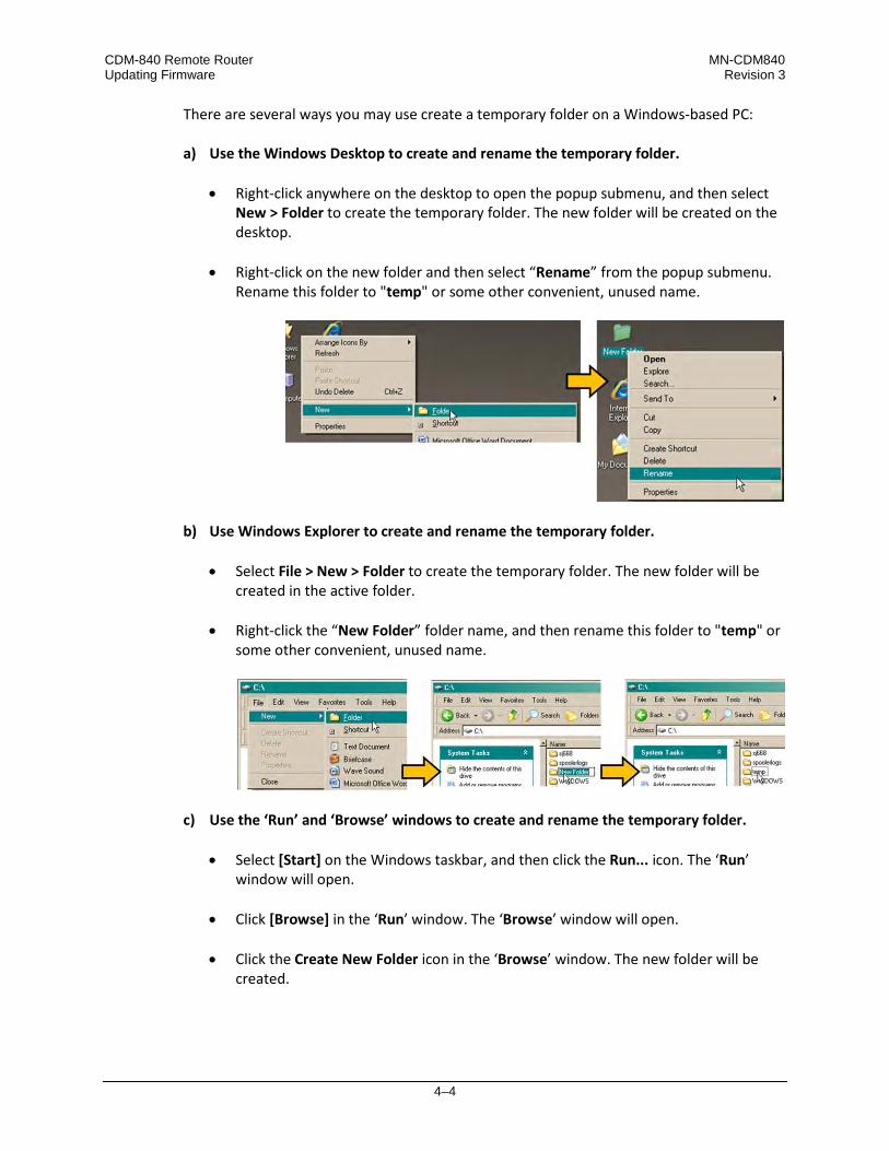
CDM-840 Remote Router MN-CDM840 Updating Firmware Revision 3
4–4
There are several ways you may use create a temporary folder on a Windows-based PC:
a) Use the Windows Desktop to create and rename the temporary folder.
• Right-click anywhere on the desktop to open the popup submenu, and then select New > Folder to create the temporary folder. The new folder will be created on the desktop.
• Right-click on the new folder and then select “Rename” from the popup submenu. Rename this folder to "temp" or some other convenient, unused name.
b) Use Windows Explorer to create and rename the temporary folder.
• Select File > New > Folder to create the temporary folder. The new folder will be created in the active folder.
• Right-click the “New Folder” folder name, and then rename this folder to "temp" or
some other convenient, unused name.
c) Use the ‘Run’ and ‘Browse’ windows to create and rename the temporary folder.
• Select [Start] on the Windows taskbar, and then click the Run... icon. The ‘Run’ window will open.
• Click [Browse] in the ‘Run’ window. The ‘Browse’ window will open. • Click the Create New Folder icon in the ‘Browse’ window. The new folder will be
created.
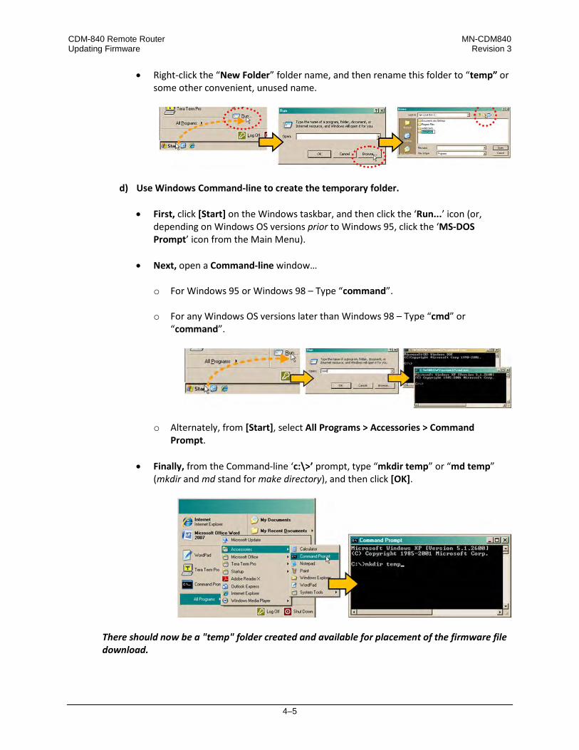
CDM-840 Remote Router MN-CDM840 Updating Firmware Revision 3
4–5
• Right-click the “New Folder” folder name, and then rename this folder to “temp” or some other convenient, unused name.
d) Use Windows Command-line to create the temporary folder.
• First, click [Start] on the Windows taskbar, and then click the ‘Run...’ icon (or, depending on Windows OS versions prior to Windows 95, click the ‘MS-DOS Prompt’ icon from the Main Menu).
• Next, open a Command-line window…
o For Windows 95 or Windows 98 – Type “command”. o For any Windows OS versions later than Windows 98 – Type “cmd” or
“command”.
o Alternately, from [Start], select All Programs > Accessories > Command Prompt.
• Finally, from the Command-line ‘c:\>’ prompt, type “mkdir temp” or “md temp”
(mkdir and md stand for make directory), and then click [OK].
There should now be a "temp" folder created and available for placement of the firmware file download.

CDM-840 Remote Router MN-CDM840 Updating Firmware Revision 3
4–6
4.3 Download and Extract the Firmware Update
Do these steps: 1. Acquire the firmware update archive file from Comtech EF Data Product Support.
• About Firmware Numbers, File Versions, and Formats: The Comtech EF Data Web site catalogues its firmware update files by product type (e.g., router, modem, etc.), the specific model, and optional hardware configurations.
• About File Archive Formats: Comtech EF Data provides its downloadable files in two compressed archive formats: *.exe (self-extracting) and *.zip (compressed). The *.exe file does not require a file archiver and compression utility program such as PKZIP for Windows, WinZip, ZipCentral, etc. (PKZIP for DOS is not supported due to file naming conventions). Comtech EF Data does not provide this utility program. Some firewalls do not allow the download of *.exe files. Download the *.zip file instead, and extract the firmware files from the archive download with a user-supplied utility program. For detailed information on handling archived files, refer to the utility program Help documentation.
2. Transfer the archive file to the temporary folder.
• Once the EXE or ZIP hyperlink is selected the ‘File Download’ window opens and prompts selection of [Open] or [Save]:
o Click [Open] to turn over file extraction to the user-supplied utility program. Be sure
to extract the firmware files to the “temp” folder created earlier.
o Click [Save] to open the ‘Save As’ window. Be sure to select and [Save] the archive *.exe or *.zip file to the “temp” folder created earlier.
o Otherwise, click [Cancel] to quit and exit the file download process.
3. Extract the firmware files from the archive file.

CDM-840 Remote Router MN-CDM840 Updating Firmware Revision 3
4–7
• (If not already done with File Download > [Open]) Extract the firmware files from the downloaded *.exe or *.zip archive file with the user-supplied utility program: o Double-click on the archive file name, and then follow the prompts provided by the
user-supplied utility program. Extract, at a minimum, two files: FW0000408xx_CDM840.bin – the Firmware Bulk image file (where ‘xx’ denotes
the revision letter), and
CDM-840ReleaseNotes_v#-#-#-#.pdf – the Firmware Release Notes PDF file (where ‘#-#-#-#’ denotes the firmware version number).
4. Confirm availability of the firmware files in the temporary folder.
There are several ways you may view the contents of the temporary folder on a Windows-based PC:
a) From the Windows Desktop:
• Double-left-click the “temp” folder saved to the Windows Desktop.
• Use Windows Explorer to locate, and then double-left-click the “temp” folder.
• Use the ‘Browse‘ window ([Start] > ...Run > [Browse]) to locate, and then double-
click the “c:\temp” folder.
b) Using Command-line:
• Type “cd c:\temp” at the Command-line prompt to change to the temporary directory created earlier using Command-line.
• Type “dir” to list the files extracted to the temporary directory from the downloaded archive file.
The firmware files have been successfully downloaded and are now available for transfer to the CDM-840.

CDM-840 Remote Router MN-CDM840 Updating Firmware Revision 3
4–8
4.4 Perform the Ethernet FTP Upload Procedure
YOU MAY PROCEED WITH THE FIRMWARE UPDATE PROCEDURE, ASSUMING THAT: • YOU HAVE CONNECTED THE CDM-840 TO A USER-SUPPLIED, WINDOWS-BASED
PC, AS FOLLOWS:
O THE PC SERIAL PORT IS CONNECTED TO THE CDM-840 ‘CONSOLE’ PORT WITH A USER-SUPPLIED SERIAL CABLE.
O THE PC ETHERNET PORT IS CONNECTED TO THE CDM-840 ‘ETHERNET | MANAGEMENT | FE’ 10/100 FAST ETHERNET PORT WITH A USER-SUPPLIED HUB, SWITCH, OR DIRECT ETHERNET CABLE CONNECTION.
O THE PC IS RUNNING A TERMINAL EMULATION PROGRAM (FOR OPERATION OF THE CDM-840 SERIAL INTERFACE) AND A COMPATIBLE WEB BROWSER (FOR OPERATION OF THE CDM-840 HTTP INTERFACE).
• YOU HAVE NOTED THE CDM-840 MANAGEMENT IP ADDRESS USING THE CDM-840 SERIAL INTERFACE, AND YOU HAVE IDENTIFIED THE FIRMWARE USING EITHER THE CDM-840 SERIAL INTERFACE OR THE CDM-840 HTTP INTERFACE ‘ADMIN | FIRMWARE’ PAGE.
• YOU HAVE OBTAINED THE LATEST FIRMWARE UPDATE FROM COMTECH EF DATA PRODUCT SUPPORT, AND THE EXTRACTED FILES ARE AVAILABLE ON THE USER PC IN AN ACCESSIBLE TEMPORARY FOLDER.
Do these steps:
1. Use Command-Line to send a ‘PING’ command to confirm proper connection and communication between the User PC and the CDM-840:
• If the Management IP Address of the unit is still not known, type “info” at the CDM-
840 Serial Interface ‘CDM-840>’ command prompt and record the displayed information. Alternately, use Serial Remote Control or the HTTP Interface:
o Serial Remote Control – Type the “<0/IPA?” remote query (without quotes) at the
CDM-840 Serial Interface CDM-840> command prompt. The unit returns the configured Management IP Address:
>0000/IPA=192.168.1.12/24 (default)
o CDM-840 HTTP Interface – View the IP Address/CIDR Mask entry on the
‘Configuration | Interface | Ethernet | FE’ page:

CDM-840 Remote Router MN-CDM840 Updating Firmware Revision 3
4–9
• Once the Management IP Address is known, use Command-line to PING – Type “ping xxx.xxx.xxx.xxx” at the Command-line prompt (where ‘xxx.xxx.xxx.xxx’ is the unit Management IP Address).
The response should confirm whether or not the unit is properly connected and communicating.
2. Use Command-line to transfer (FTP) the files from the User PC to the CDM-840:
• Type "ftp xxx.xxx.xxx.xxx" (where ‘xxx.xxx.xxx.xxx’ denotes the unit Management IP
Address).
• Enter the username and password assigned to the unit. The default username and password is “comtech”.
• Type “bin” to set the binary transfer mode.
• Type "prompt" and then type "hash" to facilitate the file transfers.
• Type "put FW-0000408xx_CDM840.bin" (where ‘xx’ denotes the revision letter) at the Command-line prompt, without quotes, to begin the file transfer. The process sequences through several blocks – this may take several minutes for the transfer to occur. Once the upgrade file is received, the image is written to Flash memory and the unit transmits the message “UPLOAD COMPLETE.”
In the event you receive the “Connection closed by remote host.” message, wait another minute before continuing. The CDM-840 update sometimes takes longer than the FTP client allows.
• Type "bye" to terminate the FTP session, and then close the Command-line window.
3. Use the CDM-840 Serial Interface or the CDM-840 HTTP Interface ‘Admin | Firmware’ page
to verify that the PC-to-Unit FTP file transfer was successful.
4. Use the CDM-840 HTTP Interface to select the firmware and reboot the unit:
a) Select the desired Boot Slot (Image):
• Go to the CDM-840 HTTP Interface ‘Admin | Firmware’ page.
• Use the ‘Boot From:’ drop-down menu to select Latest, Slot 1, or Slot 2 (in the Firmware Configuration section).
By default, the unit will boot from the Slot that stores the firmware version having the latest date (Boot From: Latest). ‘Boot From:’ may also be set to force the unit to boot up using either firmware image loaded in Slot 1 or Slot 2.
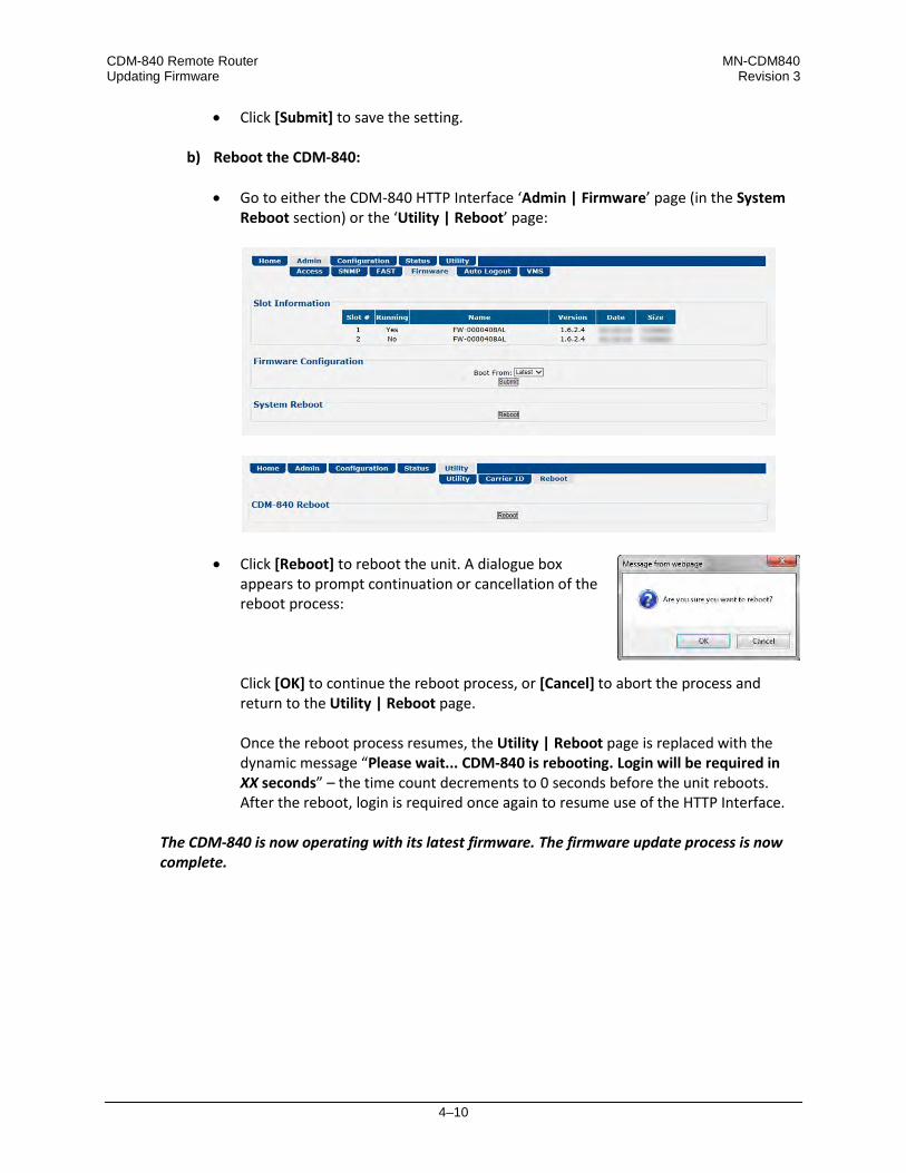
CDM-840 Remote Router MN-CDM840 Updating Firmware Revision 3
4–10
• Click [Submit] to save the setting.
b) Reboot the CDM-840:
• Go to either the CDM-840 HTTP Interface ‘Admin | Firmware’ page (in the System Reboot section) or the ‘Utility | Reboot’ page:
• Click [Reboot] to reboot the unit. A dialogue box appears to prompt continuation or cancellation of the reboot process:
Click [OK] to continue the reboot process, or [Cancel] to abort the process and return to the Utility | Reboot page. Once the reboot process resumes, the Utility | Reboot page is replaced with the dynamic message “Please wait... CDM-840 is rebooting. Login will be required in XX seconds” – the time count decrements to 0 seconds before the unit reboots. After the reboot, login is required once again to resume use of the HTTP Interface.
The CDM-840 is now operating with its latest firmware. The firmware update process is now complete.
5–1
Chapter 5. FAST ACTIVATION PROCEDURE
5.1 FAST Overview
The CDM-840 Remote Router incorporates a number of optional features. In order to permit a lower initial cost, you may purchase the unit with only the desired features enabled. If you wish to upgrade the functionality of a unit at a later date, Comtech EF Data provides Fully Accessible System Topology (FAST), which permits the purchase and activation of options through special authorization codes. You may contact Comtech EF Data Product Support to purchase these unique, register-specific Fast Access Codes, and then load these codes into the unit using the HTTP Interface (accessible by connecting your PC Ethernet port to the CDM-840 rear panel ‘ETHERNET | MANAGEMENT | FE’ port). FAST System Theory: FAST facilitates on-site upgrade of the operating feature set without removing a unit from the setup. FAST technology allows you to order a unit precisely tailored for the initial application. When your service requirements change, you can upgrade the topology of the unit to meet these requirements within minutes. This accelerated upgrade is possible because of FAST’s extensive use of the programmable logic devices incorporated into Comtech EF Data products. FAST Implementation: Comtech EF Data implements the FAST system in the modem at the factory. All FAST Features are available through the basic platform unit at the time of order – FAST allows immediate activation of available options, after confirmation by Comtech EF Data, through the CDM-840 HTTP (Web Server) Interface. FAST Accessible Options: You may order hardware options for installation either at the factory, or you can install and activate them on-site. The FAST Access Code that you purchase from Comtech EF Data enables configuration of the available hardware.

CDM-840 Remote Router MN-CDM840 FAST Activation Procedure Revision 3
5–2
5.2 FAST Activation via the HTTP Interface
Sect. 6.3.2.3 Admin | FAST (Chapter 6. ETHERNET-BASED REMOTE PRODUCT MANAGEMENT)
Use the HTTP Interface ‘Admin | FAST’ page to manage CDM-840 FAST Features. This page provides scrollable list boxes that display the availability and activation status for all FAST Features. FAST code entry/option activation control is also provided.
Figure 5-1. CDM-840 HTTP Interface – ‘Admin | FAST’ page

CDM-840 Remote Router MN-CDM840 FAST Activation Procedure Revision 3
5–3
5.2.1 FAST Configuration
The read-only table in this section displays the CDM-840 available FAST Features and the operational status for each option:
Column Description Option This column lists each available FAST Feature. Status This column identifies each FAST Feature operational parameter(s). If an option is not enabled,
the column displays this information.
The complete roster of FAST Accessible Options is as follows:
Option
CCM (VersaFEC only)
16 kbps – 256 kbps Tx Data/Symbol Rate
16 kbps – 512 kbps Tx Data/Symbol Rate
16 kbps – 1024 kbps Tx Data/Symbol Rate
16 kbps – 2.048 Mbps Tx Data/Symbol Rate
16 kbps – 5 Mbps Tx Data/Symbol Rate
16 kbps – 10 Mbps Tx Data/Symbol Rate
16 kbps – 15.35 Mbps Tx Data/Symbol Rate
CCM (DVB-S2 only) 1 – 15 Mbps Rx Data/Symbol Rate 1 – 45 Mbps Rx Data/Symbol Rate 1 – 100 Mbps Rx Data/Symbol Rate
E1 Interface Full Support E1 (hardware upgrade also required) G.703 Clock Extension dSCPC (Dynamic Single Carrier per Channel)
1) Tx Header and Payload Compression and Quality of Service (QoS)/Advanced QoS are standard (non-FAST) operational features for Comtech EF Data’s Advanced VSAT Series group of products. If these features are listed in the FAST Configuration table, they are always indicated as Enabled.
2) E1 Interface operation is not available with the ODMR-840 Reduced Form Factor Outdoor Remote Router.

CDM-840 Remote Router MN-CDM840 FAST Activation Procedure Revision 3
5–4
5.2.2 FAST Upgrade
Do these steps:
Step Task
1 Use the FAST Configuration table to view the currently installed features. Any options that appear as Disabled in the table’s Status column may be purchased as a FAST upgrade.
2 The serial number of the CDM-840 is required by Comtech EF Data when ordering FAST option upgrades. Take note of this number, provided here in the FAST Upgrade section, before contacting Comtech EF Data: Serial Number: __________________________
3 Contact Comtech EF Data Product Support: • Provide the CDM-840 Serial Number to the representative.
• Identify and purchase the desired FAST option(s).
• Obtain the invoice, the 20-digit FAST Access Code, and the FAST option
activation instructions.
4 Carefully enter the FAST Access Code into the FAST Code register text box.
5 Click [Submit] to execute the FAST Upgrade.
6 The unit either accepts or rejects the code, and the FAST Configuration table refreshes to reflect any upgrades in operation.

6–1
Chapter 6. ETHERNET-BASED REMOTE PRODUCT
MANAGEMENT
6.1 Overview
Ethernet-based Remote Product Management of the CDM-840 is available using the rear panel ‘ETHERNET | MANAGEMENT | FE’ 10/100 Fast Ethernet M&C port.
1) YOU MAY PROCEED WITH ETHERNET-BASED REMOTE PRODUCT MANAGEMENT (SNMP OR HTTP), ASSUMING THAT:
• You are operating the CDM-840 with the latest version firmware files.
• You have connected the CDM-840 to a user-supplied, Windows-based PC as
follows: o The PC serial port is connected to the CDM-840 rear panel ‘CONSOLE’
port with a user-supplied serial cable.
o The PC Ethernet port is connected to the CDM-840 rear panel ‘ETHERNET | MANAGEMENT | FE’ 10/100 Fast Ethernet M&C port with a user-supplied hub, switch, or direct Ethernet cable connection.
o The User PC is running a terminal emulation program (for operation of
the CDM-840 Serial Interface) and a compatible web browser (for operation of the CDM-840 HTTP (Web Server) Interface).
• You have noted the CDM-840 Management IP Address using the CDM-840
Serial Interface.
2) COMTECH EF DATA RECOMMENDS USE OF THE SERIAL REMOTE INTERFACE AND ETHERNET-BASED SNMP INTERFACE ONLY FOR ADVANCED USERS. ALL OTHER USERS ARE STRONGLY ENCOURAGED TO USE THE CDM-840 HTTP INTERFACE FOR MONITOR AND CONTROL (M&C) OF THE CDM-840.

CDM-840 Remote Router MN-CDM840 Ethernet-based Remote Product Management Revision 3
6–2
3) THE SERIAL AND HTTP INTERFACE FIGURES FEATURED THROUGHOUT THIS CHAPTER ARE INTENDED FOR USER REFERENCE ONLY AND ARE SUBJECT TO CHANGE. THE FIRMWARE INFORMATION (I.E., REVISION LETTERS, VERSION NUMBERS, ETC.) AS DISPLAYED MAY DIFFER FROM YOUR SETUP.
6.2 Ethernet Management Interface Protocols
The User PC affords access to Ethernet-based remote monitor and control (M&C) of the CDM-840 through two separately-operated protocols: • Simple Network Management Protocol (SNMP). This non-secure interface requires a user-
supplied Network Management System (NMS) and a user-supplied Management Information Base (MIB) File Browser.
• The CDM-840 HTTP (Web Server) Interface. This non-secure interface requires a compatible user-supplied web browser such as Internet Explorer.
6.2.1 Ethernet Management Interface Access
Figure 6-1. CDM-840 Serial Interface
Access to the CDM-840 Ethernet Management Interfaces requires you to specify the unit Management IP Address. You may obtain this information via use of a terminal emulator connected to the CDM-840 rear panel, 9-pin serial ‘CONSOLE’ port. As shown, a number of operational parameters (including the unit factory-default IP addresses) are displayed on the CDM-840 Serial Interface upon power-up of the unit. The factory-assigned default IP addresses appear in the table that follows (if otherwise assigned, use the last column to write down the IP Addresses for future reference):
Description Default Address User-assigned Address
Management IP Address 192.168.1.12 _____________________
Traffic | GE (GigE) IP Address 10.10.3.12 _____________________
Chapter 7. SERIAL-BASED REMOTE PRODUCT MANAGEMENT

CDM-840 Remote Router MN-CDM840 Ethernet-based Remote Product Management Revision 3
6–3
6.2.2 SNMP Interface
The Simple Network Management Protocol (SNMP) is an Internet-standard non-secure protocol for managing devices on IP networks. An SNMP-managed network consists of three key components: • The managed device. This includes the CDM-840 Remote Router.
• The SNMP Agent. The software that runs on the CDM-840. The CDM-840 SNMP Agent
supports both SNMPv1 and SNMPv2c.
• The user-supplied Network Management System (NMS). The software that runs on the manager.
6.2.2.1 Management Information Base (MIB) Files
MIB files are used for SNMP remote management of a unique device. A MIB file consists of a tree of nodes called Object Identifiers (OIDs). Each OID provides remote management of a particular function. These MIB files should be compiled in a user-supplied MIB Browser or SNMP Network Monitoring System server. The following MIB files are associated with operation of the CDM-840:
MIB File/Name (where ‘x’ is revision letter) Description
FW10874-2x.mib ComtechEFData Root MIB file
ComtechEFData MIB file gives the root tree for ALL Comtech EF Data products and consists of only the following OID: Name: comtechEFData Type: MODULE-IDENTITY OID: 1.3.6.1.4.1.6247 Full path: iso(1).org(3).dod(6).internet(1).private(4).enterprises(1).comtechEFData(6247) Module: ComtechEFData
FW-0000407x_CDM840.mib CDM-840 MIB file MIB file consists of all of the OIDs for CDM-840 M&C

CDM-840 Remote Router MN-CDM840 Ethernet-based Remote Product Management Revision 3
6–4
6.2.2.2 SNMP Community Strings
CAUTION – In SNMP v1/v2c, the SNMP Community String is sent unencrypted in the SNMP packets. Your network administrator must make sure that SNMP packets travel only over a secure and private network when security is a concern.
The CDM-840 uses Community Strings as a password scheme that provides authentication before gaining access to the CDM-840 Agent MIBs. They are used to authenticate users and determine access privileges to the SNMP agent. Type the SNMP Community String into the user-supplied MIB Browser or Network Node Management software. Two Community Strings are defined for SNMP access: • Read Community default = public
• Write Community default = private
For proper SNMP operation, make sure to use the CDM-840 MIB files with the associated version of the modem M&C. Read your CDM-840 Firmware Release Notes for information on the required FW/SW compatibility.
6.2.3 HTTP (Web Server) Interface
A user-supplied web browser allows the full monitoring and control (M&C) of the CDM-840 from its HTTP Interface. This non-secure embedded web application is designed for, and works best with, Microsoft Internet Explorer Version 7.0 or higher.
6.2.3.1 User Login
Type the CDM-840 Management IP Address (shown in this example as http://xxx.xxx.xxx.xxx) into the Address area of the User PC web browser:
The login page, similar to this example, opens.

CDM-840 Remote Router MN-CDM840 Ethernet-based Remote Product Management Revision 3
6–5
Enter the assigned User Name and Password – the default for both is comtech. Click [Log On]. If the User Name and Password are accepted: The CDM-840 Remote Router HTTP Interface Home page, similar to this example, appears:
6.2.3.2 HTTP Interface – Operational Features
6.2.3.2.1 Virtual Front Panel
(TOP) Default Viewing Mode
(BOTTOM) Enhanced Viewing Mode
Figure 6-2. CDM-840 Remote Router Virtual Front Panel The top of every page in the CDM-840 HTTP Interface features a read-only ‘Virtual Front Panel’ (VFP). The interface appearance differs based on the selected viewing mode – Default or Enhanced Viewing Mode (Figure 6-2): • The Default viewing mode features a text-based VFP and hyperlinks for web page access.
• Click the Enhanced Mode check box to change the interface appearance to the GUI viewing
format. The Enhanced Mode features virtual LEDs and navigation tabs for web page access.

CDM-840 Remote Router MN-CDM840 Ethernet-based Remote Product Management Revision 3
6–6
For either mode, the VFP banner displays the operational state as “Active” or “Inactive”: • “Active” indicates to you that the page as displayed is “live” and up-to-date;
• ”Inactive” indicates to you either that the page, as displayed, is “stale” and is not updating,
or that the unit is in a transitional state (e.g., a reboot is in process). Either VFP displays the CDM-840’s currently running FW (Firmware) Version and the current Working Mode as “Router” or “BPM” (Bridge Point-to-Multipoint). Additionally: • At left, the VFP reports the status of the unit. In either viewing mode, the VFP updates the
unit operation indicators in real time. In Enhanced Mode, the VFP emulates the CDM-840 front panel LEDs (see Sect. 6.2.3.2.1.1).
• At right, the VFP displays (and updates in real time) the following parameters: o Working Mode (Router or BPM) o Firmware Version o Rx Status o Rx MODCOD o Es/No (dB) o BER o RSL (dBm)
6.2.3.2.1.1 Virtual Front Panel LEDs
The Enhanced Mode virtual LEDs provide ‘heads-up’ operational status indicators that react to any changes made to unit operation, and convey operational states. To ensure that your web browser correctly displays the LED feature, Comtech EF Data recommends that you follow these configuration steps (this example uses Microsoft Internet Explorer):
Step Task
1 On the Tools menu, click Internet Options.
2 On the General tabbed page: Under Browsing history, click [Settings].
3 On the Temporary Internet Files and History Settings page: Under Check for Newer Versions of Stored Pages: click Every Time I visit the webpage.
4 Click [OK] to save the selection and close the Temporary Internet Files and History Settings page.
5 Click [OK] to close the Internet Options page.
6 Restart your browser.
The Enhanced Mode virtual LEDs indicate the active operating state of the unit as follows:
LED State Condition
UNIT STATUS Green No Unit Faults or Alarms. Amber No Unit Faults, but an Alarm exists. Red A Unit Fault exists (Example: PSU fault).
STORED EVENT Amber There is a Stored Event in the log, which can be viewed from the HTTP Interface. Off There are no Stored Events.
ONLINE Green The Unit is On Line, and carrying traffic.

CDM-840 Remote Router MN-CDM840 Ethernet-based Remote Product Management Revision 3
6–7
LED State Condition
Off The Unit is Off Line (standby) – forced by externally connected 1:1 or 1:N redundancy system.
TEST MODE Amber A Test Mode is selected. Off There is no Test Mode currently selected.
TRANSMITTER ON
Green The Transmitter Carrier is On. Red A Fault exists that causes the unit to turn off the carrier. Off The Transmitter Carrier is Off.
Tx TRAFFIC
Green (solid) No Tx Traffic Faults, no packets.
Green (blinking) No Tx Traffic Faults, blinks when a packet is being transmitted to the satellite link from this unit.
Amber A Tx Traffic Alarm exists. Red Tx Traffic has a Fault. Off The Tx is turned off.
Rx TRAFFIC
Green (solid) No Rx Traffic Faults (demod and decoder are locked, everything is OK).
Green (blinking) No Rx Traffic Faults, blinks when a packet is being received from the satellite link to this unit.
Amber Rx Traffic has an Alarm. Red Rx Traffic has a Fault.
GE LINK/ACTIVITY
Green (solid) Traffic Ethernet is connected, but no traffic exists. Green (blinking) Ethernet activity detected.
Off Traffic Ethernet is not connected.
6.2.3.2.2 Navigation
The CDM-840 HTTP Interface provides navigation aids at the top of each page, just below the Virtual Front Panel: • The Default viewing mode uses page hyperlinks. After you
click a navigation hyperlink, you may click an available primary page hyperlink. In turn, any nested hyperlinks appear for further selection.
• Enhanced Mode uses navigation tabs. After you click a navigation tab, you may click an available primary page tab. In turn, any nested tabs appear for further selection.
This manual uses a naming format for all web pages to indicate the depth of navigation needed to view the subject page: “Top Level Select | Primary Page Select | Nested Page Select”. For example, “Status | Statistics | Traffic” instructs you to “first click the top-level ‘Status’ navigation tab; then, click the ‘Statistics’ primary page tab; finally, click the nested ‘Traffic’ tab.”

CDM-840 Remote Router MN-CDM840 Ethernet-based Remote Product Management Revision 3
6–8
6.2.3.2.3 Page Sections
Each page features one or more sections. The title at the upper-left corner of each page or page section provides indicates its operational features. Each section can feature editable fields, action buttons, and read-only displays that are specific to that section. This manual explains the purpose and operation for each web page on a per-page, per-section basis.
6.2.3.2.4 Action Buttons
Action buttons are important in the HTTP Interface. Click an action button to do one of these tasks: • Reset changed parameters to remove unsaved changes.
• Permanently save changes.
• Refresh the page with current data.
If you edit a field, make sure to click the action button before you leave the page. If you go to another page without first clicking the action button, your changes are not saved.
6.2.3.2.5 Drop-down Lists
A drop-down list lets you choose from a list of selections. Left-click the drop-down button to open the list. Then, left-click on an item to select that choice.
6.2.3.2.6 Text or Data Entry
Text boxes let you type data into a field. An action button may be associated with a single text box, or a group of text boxes. For any text box, left-click anywhere inside the box, type the desired information into that field, and be sure to press [ENTER] when done. Click the related action button to save the data.
If you edit a field, make sure to click the action button before you leave the page. If you go to another page without first clicking the action button, your changes are not saved.

CDM-840 Remote Router MN-CDM840 Ethernet-based Remote Product Management Revision 3
6–9
6.2.3.3 HTTP Interface Menu Tree Diagram
Any diagram block that is marked with (*) denotes a page that is functional only when that optional FAST Feature has been purchased and activated. The diagram block marked with (**) denotes that this page is functional only when a VIPERSAT MANAGEMENT SYSTEM (VMS), and a Block Up Converter (BUC) OR a Low Noise Block Down Converter (LNB) is installed and is recognized as operational.
Figure 6-3 Illustrates the menu hierarchy for the CDM-840 HTTP Interface. It features five navigation tabs (shown in blue) located below the VFD at the top of each page. Primary page tabs (green) and nested page tabs (yellow or grey) grant access to individual web pages.
Figure 6-3. CDM-840 HTTP Interface – Menu Tree (FW Ver. 1.6.2.5)

CDM-840 Remote Router MN-CDM840 Ethernet-based Remote Product Management Revision 3
6–10
6.3 HTTP Interface Page Descriptions
1) Access to and availability of certain CDM-840 HTTP Interface pages depends upon the optional FAST Features purchased for operation, and/or the detected presence of auxiliary products (e.g., VIPERSAT Management System, Redundancy Switches, LNCs or BUCs, etc.) installed and configured for use with the CDM-840. Such operational restrictions will be noted in the subsections that follow through the end of this chapter.
2) The HTTP Interface page figures that follow depict the interface with Enhanced Mode selected. They do not show the page banner and VFP (Virtual Front Panel). These figures depict operational examples that will vary from your actual implemented network. They are provided for reference purposes only.
6.3.1 Home Pages
Click the Home or Contact tab to continue.
6.3.1.1 Home | Home
Use this page to identify the product and its current operating firmware version. Click the Home navigation or page tab to return to this page from anywhere in the HTTP Interface.
Figure 6-4. Home | Home Page

CDM-840 Remote Router MN-CDM840 Ethernet-based Remote Product Management Revision 3
6–11
6.3.1.2 Home | Contact
For all product support, please call:
+1.240.243.1880
+1.866.472.3963 (toll free USA)
Figure 6-5. Home | Contact Page

CDM-840 Remote Router MN-CDM840 Ethernet-based Remote Product Management Revision 3
6–12
6.3.2 Admin (Administration) Pages
Use these pages to set up user access, manage the firmware load preferences, and activate CDM-840 FAST features.
The Admin pages are available only to users who have logged in using the Administrator Name and Password.
Click the Access, SNMP, FAST, Firmware, Auto Logout, or VMS tab to continue.
6.3.2.1 Admin | Access
The Administrator must use this page to manage the CDM-840 HTTP Interface user access settings.
Figure 6-6. Admin | Access Page
User Access
• Enter a User Name. The User Name can be any alphanumeric combination with a maximum length of 15 characters. The factory default is comtech.
• Enter a Password. The Password can be any alphanumeric combination with a maximum length of 15 characters. The factory default is comtech.
• Re-enter the new Password in the Confirm Password text box. Click [Submit] to save.

CDM-840 Remote Router MN-CDM840 Ethernet-based Remote Product Management Revision 3
6–13
6.3.2.2 Admin | SNMP
Sect. 6.2.2 SNMP Interface
The Administrator must use this page to manage the CDM-840 SNMP (Simple Network Management Protocol) settings.
Figure 6-7. Admin | SNMP Page
SNMP Configuration
• Enter an SNMP Trap Destination IP Address in the form XXX.XXX.XXX.XXX. Click [Submit] to save. • Enter an SNMP Read Community string. This string can be any combination of characters
and a length of 4 to 15 characters. The factory default string is public.
Click [Submit] to save. • Enter an SNMP Write Community string. This string can be any combination of characters
and a length of 4 to 15 characters. The factory default string is private. Click [Submit] to save.

CDM-840 Remote Router MN-CDM840 Ethernet-based Remote Product Management Revision 3
6–14
6.3.2.3 Admin | FAST
The CDM-840 has a number of optional features that you may activate after you purchase their unique authorization codes from Comtech EF Data Product Support. Use this page to enter these Fully Accessible System Topology (FAST) Access Codes.
See Chapter 5. FAST ACTIVATION PROCEDURE for the complete information on activating your FAST Features via the CDM-840 HTTP Interface.
QoS and Tx and Rx Header and Payload Compression are standard (non-FAST) operational features for Comtech EF Data’s Advanced VSAT Series group of products. If these features are listed in the FAST Configuration table, they are always indicated as Enabled.
Figure 6-8. Admin | FAST Page

CDM-840 Remote Router MN-CDM840 Ethernet-based Remote Product Management Revision 3
6–15
6.3.2.4 Admin | Firmware
Chapter 4. UPDATING FIRMWARE
The Administrator must use this page to select which image (boot Slot #) is to be designated as the active running firmware image – i.e., the version loaded for operation upon power-up or soft reboot.
Figure 6-9. Admin | Firmware Page
Firmware Information
This read-only status section displays the operating status for the CDM-840 FW-0000408 firmware versions loaded into Slot #1 and Slot #2.
Firmware Configuration
Use the Boot From: drop-down list to select Latest, Slot 1, or Slot 2. The default selection is Latest, in which the unit will automatically select the image that contains the most current firmware. Click [Submit] to save. Note that the Firmware Information section, which in Figure 6-9 displays Slot #1 as the designated active running firmware image, will not update until after the unit is rebooted.
System Reboot
Click [Reboot] to reboot the CDM-840. Once the unit reboots, you must log in once again to resume use of the HTTP Interface. See the Utility | Reboot page (Sect. 6.3.5.3) for further information.

CDM-840 Remote Router MN-CDM840 Ethernet-based Remote Product Management Revision 3
6–16
6.3.2.5 Admin | Auto Logout
The Administrator must use this page to execute the Auto Logout security measure. When you configure Auto Logout, the active session terminates if the unit remains idle (i.e., when no user activity occurs) beyond your designated Logout Time. You must then log in with a valid user name and password to resume use of the CDM-840 HTTP Interface.
Figure 6-10. Admin | Auto Logout Page
Auto Logout Configuration
Set an automatic logout time to safeguard access to an already logged-in unit: • Enter a value from 1 to 15 minutes into the Logout Time box to configure this feature.
• Enter a value of 0 to disable this feature. Click [Submit] to save.

CDM-840 Remote Router MN-CDM840 Ethernet-based Remote Product Management Revision 3
6–17
6.3.2.6 Admin | VMS
VMS v3.x.x VIPERSAT Management System User Guide (CEFD P/N MN/22156)
Figure 6-11. Admin | VMS Page
Management System Configuration
The valid operating ranges for items in this section are provided in parentheses. • Network ID (1 to 254) – The Network ID designation defines to which network the Remote
Router belongs. All devices in a common network will have the same Network ID. VMS uses the Network ID to identify Vipersat units within a network, and allows the VMS to manage multiple networks, each with its own unique network ID number.
Starting with FW Ver. 1.6.2.X, the Network ID is configured in the CTOG-250 and automatically distributed to all CDM-840s that are locked and receiving the Outbound Carrier from the CTOG-250.
• Management Base Port– The Management Base Port sets the starting IP port addressing for all VMS and ACM messages.
CAUTION – MAKE NOTE OF THE FOLLOWING: o Use this setting ONLY if network port addressing is in contention. You
should otherwise leave this setting at default (hex) C000 (dec) 49152 to avoid unnecessary configuration changes.
o If you change this port number (i.e., enter a value and click [Submit] to save), it will affect internal management operations across the entire network. You will be required to make configuration changes to all modems.
o While this page is operational only when the optional VIPERSAT MANAGEMENT SYSTEM (VMS) is installed and operational, the Management Base Port number is essential to proper operations with or without the VMS feature.
CDM-840 Remote Router MN-CDM840 Ethernet-based Remote Product Management Revision 3
6–18
• Management Multicast IP – This is the Multicast IP Address assigned to all Vipersat network units to receive management messages from the VMS. This address must match the VMS Transmit Multicast Address.
Starting with FW Ver. 1.6.2.X, the Management Multicast ID is configured in the CTOG-250 and automatically distributed to all CDM-840s that are locked and receiving the Outbound Carrier from the CTOG-250.
Once the CDM-840 is registered in the Vipersat network, the VMS takes full management control of the Data Rate, Symbol Rate, Frequency, and ModCod demodulator parameters.
Management System Status
This read-only section provides available information on the VMS’s IP Address, Registration Status, and Version.

CDM-840 Remote Router MN-CDM840 Ethernet-based Remote Product Management Revision 3
6–19
6.3.3 Configuration Pages
MEO (Medium Earth Orbit) is not available in this firmware release. The MEO tab and its nested page, while available and selectable on this interface, are therefore NOT OPERATIONAL.
Use the Configuration pages to configure all unit parameters. Click the Interface, WAN, Network, ECM, or dSCPC tab to continue.
6.3.3.1 Configuration | Interface Pages
Click the FE Mgt, GE, or E1 tab to continue.
6.3.3.1.1 Configuration | Interface | Fe Mgt
1) The IP Addresses for the FE and GigE Interfaces must be different and on separate subnets.
2) The ‘ETHERNET | MANAGEMENT | FE’ port will always be in Router Mode. The ‘ETHERNET | TRAFFIC | GE’ port will change from Router Mode to BPM Mode when the Working Mode is changed.
Use this page to configure the rear panel ‘ETHERNET | MANAGEMENT | FE’ 10/100 Fast Ethernet M&C port. Note that this port serves as the dedicated Ethernet-based monitor and control interface between the CDM-840 and the User PC.
Figure 6-12. Configuration | Interface | FE Mgt Page
FE – Management Interface
The valid operating ranges for items in this section are provided in parentheses. • MAC Address (read-only) – Ethernet MAC Addresses are configured at the factory and
cannot be changed. This MAC Address is unique for each available port.
• IP Address / CIDR Mask (8 to 30) – Use this box to enter the IP Address and CIDR (Classless Inter-Domain Routing) Subnet Mask.
The configured subnets must be unique when in Router Mode. Overlapping the subnets is not allowed and such configuration requests will be rejected.

CDM-840 Remote Router MN-CDM840 Ethernet-based Remote Product Management Revision 3
6–20
• Link Configuration – Use the drop-down list to select the line speed and duplex setting for the CDM-840 FE interface. The available settings are Auto*, 10 BaseT/Half Duplex, 10 BaseT/Full Duplex, 100 BaseT/Half Duplex, or 100 BaseT/Full Duplex.
* Auto is the recommended configuration selection.
• Negotiated Link Mode (read-only) – The actual negotiated line speed and duplex setting for the FE Interface is displayed here. The viewable settings are: 10 BaseT/Half Duplex, 10 BaseT/Full Duplex, 100 BaseT/Half Duplex, or 100 BaseT/Full Duplex.
Click [Submit] to save.
6.3.3.1.2 Configuration | Interface | GE
1) The IP Addresses for the M&C and Traffic Interfaces must be different and on separate subnets.
2) The ‘ETHERNET | TRAFFIC | GE’ port will not have an IP address when you set Working Mode to BPM.
Use this page to configure the rear panel ‘ETHERNET | TRAFFIC | GE’ 10/100/1000 BaseT Gigabit Ethernet port. This port should be connected to the user LAN network, and is used for Ethernet data traffic.
Figure 6-13. Configuration | Interface | GE page
GE Interface (Bridge Port)
The read-only information and configuration options provided here are identical to those featured on the Configuration | Interface | FE Mgt page. See Sect. 6.3.3.1.1 for information about using these features.
CDM-840 Remote Router MN-CDM840 Ethernet-based Remote Product Management Revision 3
6–21
VLAN Configuration
Appendix E. BPM (BRIDGE POINT-TO-MULTIPOINT) OPERATION
• VLAN Port Mode – This setting applies only when you set the Working Mode to BPM. Use the drop-down list to select the port mode as Trunk or Access. Note the following:
o VLAN Trunk Mode is the default mode for BPM where all packets (with and without
VLAN tags) arriving at the CTOG-250 and CDM-840 pass through the system without modification. A trunked port can pass two or more VLANs on the interface.
o VLAN Access Mode forces the Traffic Interface to carry traffic for only one user-configured VLAN.
• Access Port VLAN ID – Enter a valid numeric port ID, from 1 to 4095. This ID is valid only
when Working Mode is set as BPM and the VLAN Port Mode is set to Access.
When the VLAN Port Mode is set to Access, VLAN tagged packets from WAN to LAN having a VLAN ID that matches the “Access Port VLAN ID” will have the outer VLAN tag removed and then transmitted by the ‘ETHERNET | TRAFFIC | GE’ port. In this mode, packets coming in to the port will be tagged with the “Access Port VLAN ID”. If the outermost VLAN tag IDs for WAN to LAN packets do not match the “Access Port VLAN ID”, they will be dropped. Click the (Link to Working Mode Configuration Page) hyperlink to access the Configuration | Network | Working Mode page (Sect. 6.3.3.3.3).
Click [Submit] to save.

CDM-840 Remote Router MN-CDM840 Ethernet-based Remote Product Management Revision 3
6–22
6.3.3.1.3 Configuration | Interface | E1 Pages
Appendix K. RAN/WAN OPTIMIZATION
These pages are functional only when the “G.703 E1 Interface / RAN Optimization” FAST and hardware options are installed and activated.
Click the Configuration or Time Slots tab to continue.
6.3.3.1.3.1 Configuration | Interface | E1 | Configuration
Figure 6-14. Configuration | Interface | E1 | Configuration Page
E1 Configuration
• Line Type – Use the drop-down list to select Framed, Framed-CRC, or Unframed.
• Line Coding – Use the drop-down list to select HDB3 or AMI. • WAN Loopback and Terrestrial Loopback – Use the drop-down lists to select Disable or
Enable. Click [Submit] to save.
RAN Optimization
Appendix K. RAN/WAN OPTIMIZATION
Use RAN Optimization to reduce the satellite bandwidth required for mobile backhaul. Use this section to select the level of optimization needed to achieve the desired link quality and bandwidth savings.

CDM-840 Remote Router MN-CDM840 Ethernet-based Remote Product Management Revision 3
6–23
• Hub RAN Optimizer IP Address – Enter an IP address in the form XXX.XXX.XXX.XXX.
• Hub RAN Optimization E1 Port ID – Enter a numeric identification string for the rear panel ‘G.703 | IN / OUT’ port pair, corresponding to a specified corresponding port on the CXU-810 RAN Optimizer.
• Optimization Level – Use the drop-down list to select Best Performance or Best
Compression. • Jitter Buffer Latency – Use the drop-down list to select 10ms, 20ms, 30ms, 40ms, or 50ms. • Alarm Relay – Use the drop-down list to select Disable or Enable. Select Enable to both
trigger the logging of operational faults or alarms on the Status | Statistics | E1 | Transmit / Receive pages and toggle on the STORED EVENT LED on the HTTP Interface Virtual Front Panel (Sect. 6.2.3.2.1.1).
Click [Submit] to save.
E1 Port
Access to G.703 Clock Extension operation defaults to Enable when this FAST option is activated. Use this drop-down list to otherwise select Disable. Click [Submit] to save.

CDM-840 Remote Router MN-CDM840 Ethernet-based Remote Product Management Revision 3
6–24
6.3.3.1.3.2 Configuration | Interface | E1 | Time Slots
Figure 6-15. Configuration | Interface | E1 | Time Slots Page
Time Slot Configuration
Time Slots may be selected for transmission or reception up to the maximum dictated by the selected transmit or receive data rate, and may be selected in prioritized order. For example, if the Time Slot format is set to Mostly 64k TCHs (Time Channels), the maximum number of Time Slots that can be dropped or inserted is 64 kbps. From left to right:
Column Description Slot This read-only column identifies the assignable Time Slot (0 through 31). Selection On / Off Select the Time Slot as On or Off. Priority Use the drop-down list to select the Time Slot priority:
• Priority 1 • Priority 2 • Priority 3.
Format Use the drop-down list to select the Time Slot format: • Mostly 8k TCHs • Mostly 16k TCHs • Mostly 32k TCHs • Mostly 64k TCHs
Click [Submit] to save.

CDM-840 Remote Router MN-CDM840 Ethernet-based Remote Product Management Revision 3
6–25
6.3.3.2 Configuration | WAN pages
Use the WAN pages to configure WAN-based operating parameters. Click the Demod, Mod, QoS, Label, Compression, BUC, or LNB tab to continue.
6.3.3.2.1 Configuration | WAN | Demod Pages
Click the Config or ACM tab to continue.
6.3.3.2.1.1 Configuration | WAN | Demod | Config
Use this page to configure CDM-840 Rx demodulator operations. `
Figure 6-16. Configuration | WAN | Demod | Config Page

CDM-840 Remote Router MN-CDM840 Ethernet-based Remote Product Management Revision 3
6–26
Demodulator
The valid operating range for each item in this section is noted in parentheses. • Data Rate (read-only) – This section displays the data rate, which is a snapshot of the
MODCOD currently being received.
• Symbol Rate (1000 to 62000) – Enter the Active and Alternate symbol rates in ksps. Click [Submit] to save.
The Alternate column and its defined Symbol and Data rates are used only when the Automatic Demod Configuration Switch has been enabled.
• Rx Frequency (950 to 2150 MHz) – Enter the Active and Alternate Rx frequencies in MHz.
• MODCOD – This section ALWAYS defaults to Auto mode. • Gold Code (000000 to 262141) – The Gold-n Index descrambling code indicates the Physical
Layer spreading sequence number. The default setting is all 0s.
• Es/No Alarm Point (0.1 to 16.0) –This value, as calculated by the demodulator, is the energy per symbol bit (Es) divided by the noise spectral density (No). Enter the Es/No Alarm Point value, in dB.
Click [Submit] to save.
The Alternate column and its defined Symbol and Data rates are used only when the Automatic Demod Configuration Switch has been enabled.
• Roll Off (read-only) – The Rx Alpha Rolloff (α) dictates how fast the spectral edges of the
carrier are attenuated beyond the 3 dB bandwidth. Roll Off is identified here as 20%, 25%, or 35%.
• Frame (read-only) – The Framing type is identified here as either Normal or Short.

CDM-840 Remote Router MN-CDM840 Ethernet-based Remote Product Management Revision 3
6–27
• Pilots (read-only) – Pilots operation is identified here as Off or On. • Spectrum Invert (read-only) – Spectrum Inversion operation is identified here as either
Normal or Rx Spectrum Inverted.
Automatic Demod Configuration Switch
The Automatic Demod Configuration Switch allows you to enable and configure the “Alternate Demod” functionality. This feature allows you to pre-stage a new configuration for the outbound carrier – i.e., increase, decrease, or move the CTOG-250’s Outbound carrier. It is expected that this will be done as part of normal operations. Do these steps:
Step Task 1 Define the new desired outbound carrier parameters (symbol rate, frequency). 2 Configure the “Alternate Demod” configuration for all CDM-840s on the same Outbound Carrier
(CTOG-250). 3 Configure the CTOG-250 to the new matching Tx parameters. 4 At this point, all of the CDM-840s will unlock from the old carrier, wait the “Initial Switch Timer” seconds and
then try to Receive Lock to the “Alternate Demod” configuration. 5 If the initial attempt fails, then the demod will switch back and forth between the Active and the Alternate
configuration until lock is achieved. This will occur every “Search Switch Timer” seconds. 6 Once a lock occurs, the successful configuration becomes the “Active” configuration and the other
configuration becomes the “Alternate” configuration. • Switch Enable – Use the drop-down list to set automatic switching between demod
configurations as Enable or Disable. • Initial Switch Timer – Enter a value from 10 to 3600 seconds. Use this setting to specify how
long to wait after the demod goes unlocked before trying to lock onto the “Alternate Demod” parameters.
• Search Switch Timers – Enter a value from 30 to 3600 seconds. Use this setting to specify
how long to wait between alternating attempts to “search” for the correct demod configuration. The “search” will stop once the demod has successfully locked onto the CTOG-250’s carrier.
Click [Submit] to save.
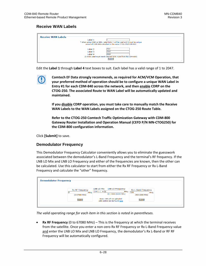
CDM-840 Remote Router MN-CDM840 Ethernet-based Remote Product Management Revision 3
6–28
Receive WAN Labels
Edit the Label 1 through Label 4 text boxes to suit. Each label has a valid range of 1 to 2047.
Comtech EF Data strongly recommends, as required for ACM/VCM Operation, that your preferred method of operation should be to configure a unique WAN Label in Entry #1 for each CDM-840 across the network, and then enable CDRP on the CTOG-250. The associated Route to WAN Label will be automatically updated and maintained. If you disable CDRP operation, you must take care to manually match the Receive WAN Labels to the WAN Labels assigned on the CTOG-250 Route Table. Refer to the CTOG-250 Comtech Traffic Optimization Gateway with CDM-800 Gateway Router Installation and Operation Manual (CEFD P/N MN-CTOG250) for the CDM-800 configuration information.
Click [Submit] to save.
Demodulator Frequency
This Demodulator Frequency Calculator conveniently allows you to eliminate the guesswork associated between the demodulator’s L-Band Frequency and the terminal’s RF frequency. If the LNB LO Mix and LNB LO Frequency and either of the frequencies are known, then the other can be calculated. Use this calculator to start from either the Rx RF Frequency or Rx L-Band Frequency and calculate the “other” frequency.
The valid operating range for each item in this section is noted in parentheses. • Rx RF Frequency (0 to 67080 MHz) – This is the frequency at which the terminal receives
from the satellite. Once you enter a non-zero Rx RF Frequency or Rx L-Band Frequency value and enter the LNB LO Mix and LNB LO Frequency, the demodulator’s Rx L-Band or RF RF Frequency will be automatically configured.

CDM-840 Remote Router MN-CDM840 Ethernet-based Remote Product Management Revision 3
6–29
Enter the Rx RF Frequency in MHz. Click [Submit]. Upon submission, if you enter the LNB LO Frequency, the resulting Rx RF Frequency displays.
If the LNB LO Frequency is left at the default configuration of zero, the Rx RF Frequency will not be calculated.
The LNB LO Mix and LNB LO Frequency entries are provided for calculation purposes only. LNB configuration is not updated as a result of configuring these parameters.
• LNB LO Mix – Use this drop-down list to select the LNB LO (Low Oscillator) Mix as Upconv
(SUM): RF=LO+LBand or DownConv (Diff): RF=LO-LBand.
Consult your LNB adjunct product datasheet or its Installation and Operation Manual for the type of LNB (Upconverter [Sum] or Downconverter [Diff]) being used.
• LNB LO Frequency – Enter the known LNB Rx LO (Low Oscillator) Frequency in MHz.
Consult your LNB adjunct product datasheet or its Installation and Operation Manual for the LO Frequency.
• Rx L-Band Frequency (950 to 2150 MHz for L-Band, 50 to 180 MHz for IF) – Enter the L-Band or IF-Band frequency in MHz. Click [Submit].

CDM-840 Remote Router MN-CDM840 Ethernet-based Remote Product Management Revision 3
6–30
6.3.3.2.1.2 Configuration | WAN | Demod | ACM (Adaptive Coding and Modulation)
VersaFEC ACM requires Version 1.3.2 or higher firmware and the appropriate FAST code for the maximum operating symbol rate.
Use this page to configure CDM-840 Rx ACM operations.
Figure 6-17. Configuration | WAN | Demod | ACM Page
Outbound ACM allows you to configure a CTOG-250 Comtech Traffic Optimization Gateway to dynamically adjust the DVB-S2 MODCODs that are sent to each CDM-840 Remote Router, based on the conditions at that remote site. These conditions include antenna size, look angle and satellite band, as well as the current environmental conditions. Each CDM-840 will automatically and periodically send its Rx Es/No to the associated CTOG-250. Requirements for ACM operation are as follows: • Outbound ACM must be enabled at the CTOG-250.
• When Outbound ACM is disabled at the CTOG-250, all packets will revert to the “VCM Only
MODCOD” which is configured in each QoS Group.
• Each CDM-840 must be locked to the Shared Outbound carrier from the CTOG-250.
If a CDM-840 Remote Router reports that its demod is unlocked, the CTOG-250 ACM Controller will assign the lowest MODCOD (QPSK 1/4) to that remote in an effort to “recover” the remote. Once the remote locks again, the ACM algorithm adapts to the correct MODCOD for the reported Rx Es/No.
• A return packet path is required from the CDM-840 to the CTOG-250 Management interface.

CDM-840 Remote Router MN-CDM840 Ethernet-based Remote Product Management Revision 3
6–31
Rx ACM Configuration
• Rx Max MODCOD – Use the drop-down list to select the maximum demodulation type and FEC rate (MODCOD). The available DVB-S2 selections are: • QPSK 1/4 • QPSK 1/3 • QPSK 2/5 • QPSK 1/2 • QPSK 3/5 • QPSK 2/3 • QPSK 3/4 • QPSK 4/5 • QPSK 5/6 • 8PSK 3/5 • 8PSK 2/3 • 8PSK 3/4 • 16APSK 2/3 • 16APSK 3/4 • 16APSK 5/6 • 16APSK 9/10 • 32APSK 3/4 • 32APSK 4/5 • 32APSK 5/6 • 32APSK 9/10
• Rx Target Es/No Margin – Use the drop-down list to select a margin value, in 0.5 dB
increments, from 0.0 to 4.5 dB.
The ACM system is designed to switch based on thresholds that correspond to a BER of 5 x 10⁻⁸ for each MODCOD. However, in order to prevent oscillation around two MODCODs at this exact value, 0.3 dB of hysteresis has been added.
• CIR Threshold MODCOD – Use the drop-down list to select the Commited Information Rate
(CIR) Threshold MODCOD that is reported to the CTOG-250 and used by the Highly Degraded Remote feature. As long at the remote maintains a signal quality which corresponds to the CIR Threshold MODCOD or above, the CTOG-250 will continue to honor the configured CIR as expected. If the Outbound assigned MODCOD for a given remote drops below the configured CIR Threshold MODCOD, the Qos Scheduler will scale back, if required, the throughput for the remote in order to prevent a highly-degraded remote from affecting the throughput of the entire outbound carrier.
Click [Submit] to save.
Rx ACM Status
Information is presented in this read-only section as follows: • Rx ACM Enable – Identifies ACM operation on the CTOG-250 as Enabled or Disabled.
• Time Since Last Controller Announcement – Amount of time in seconds since the CDM-840
received an announcement message from the CTOG-250. • Max Time Since Last Controller Announcement – Maximum amount of time since the last
announcement message was received from the CTOG-250. • ACM/VCM Controller IP Address – The assigned IP Address for the Controller. This will be
the Management IP Address for the associated CTOG-250.

CDM-840 Remote Router MN-CDM840 Ethernet-based Remote Product Management Revision 3
6–32
6.3.3.2.2 Configuration | WAN | Mod (Modulator) Pages
Click the Config, ACM, or DPC tab to continue.
6.3.3.2.2.1 Configuration | WAN | Mod | Config
Use this page to configure CDM-840 Tx modulator operations.
Figure 6-18. Configuration | WAN | Mod | Config Page
Modulator

CDM-840 Remote Router MN-CDM840 Ethernet-based Remote Product Management Revision 3
6–33
The upper range of Data and Symbol Rate selection requires activation of the TRANSMIT DATA RATE FAST option.
Select or enter the desired FEC Type, Tx Frequency, MODCOD, Tx Scrambler, Spectrum Invert, and Carrier State settings. Click [Submit] to save. The valid operating range for each item in this section is noted in parentheses: • Data Rate (16 to 15343 kbps) – Enter The CDM-840 Tx Data Rate in kbps. Click [Submit] to
save.
When Adaptive Coding and Modulation (ACM) is set to Enable, the Data Rate is set automatically. Manual configuration of Data Rate is disabled and the appearance of the Data Rate section changes as follows:
• Symbol Rate (16 to 4500 ksps) – Enter The CDM-840 Tx Symbol Rate in ksps. Click [Submit]
to save.
• FEC Type – At present, VersaFEC is the sole available FEC type.
• Tx Frequency (950 to 2150 MHz) – Enter The CDM-840 Tx frequency in MHz. • MODCOD (applicable only to CCM Mode) – Use the drop-down list to select the Modulation
type and FEC rate (MODCOD). The available selections are: o VersaFEC MODCOD 0 – BPSK 0.488 o VersaFEC MODCOD 6 – 8-QAM 0.711 o VersaFEC MODCOD 1 – QPSK 0.533 o VersaFEC MODCOD 7 – 8-QAM 0.780 o VersaFEC MODCOD 2 – QPSK 0.631 o VersaFEC MODCOD 8 – 16-QAM 0.731 o VersaFEC MODCOD 3 – QPSK 0.706 o VersaFEC MODCOD 9 – 16-QAM 0.780 o VersaFEC MODCOD 4 – QPSK 0.803 o VersaFEC MODCOD 10 – 16-QAM 0.829 o VersaFEC MODCOD 5 – 8-QAM 0.642 o VersaFEC MODCOD 11 – 16-QAM 0.853
• Tx Scrambler – Use the drop-down list to select the Tx Scrambler as Off or Normal.
• Roll Off – The Tx Alpha Rolloff (α) dictates how fast the spectral edges of the carrier are
attenuated beyond the 3 dB bandwidth. With 20% rolloff the edge falls off more quickly than with 25% and 35%. Use the drop-down list to set the expected filter Tx Alpha Rolloff (α) of the carrier as 20%, 25%, or 35%. The default selection is 20%.
• Spectrum Invert – Use the drop-down list to select the Tx Spectrum Invert as Normal or Tx Spectrum Inverted.
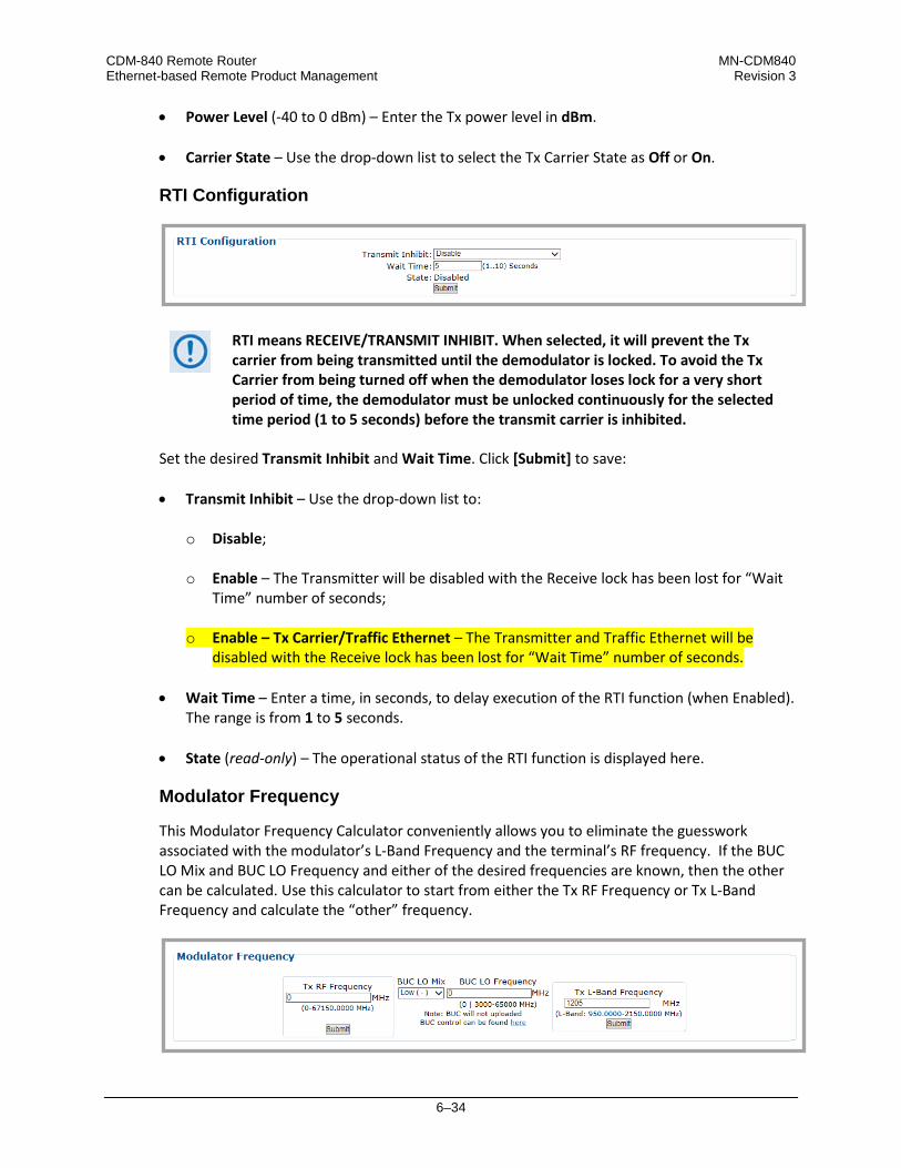
CDM-840 Remote Router MN-CDM840 Ethernet-based Remote Product Management Revision 3
6–34
• Power Level (-40 to 0 dBm) – Enter the Tx power level in dBm.
• Carrier State – Use the drop-down list to select the Tx Carrier State as Off or On.
RTI Configuration
Set the desired Transmit Inhibit and Wait Time. Click [Submit] to save: • Transmit Inhibit – Use the drop-down list to:
o Disable;
o Enable – The Transmitter will be disabled with the Receive lock has been lost for “Wait
Time” number of seconds;
o Enable – Tx Carrier/Traffic Ethernet – The Transmitter and Traffic Ethernet will be disabled with the Receive lock has been lost for “Wait Time” number of seconds.
• Wait Time – Enter a time, in seconds, to delay execution of the RTI function (when Enabled).
The range is from 1 to 5 seconds. • State (read-only) – The operational status of the RTI function is displayed here.
Modulator Frequency
This Modulator Frequency Calculator conveniently allows you to eliminate the guesswork associated with the modulator’s L-Band Frequency and the terminal’s RF frequency. If the BUC LO Mix and BUC LO Frequency and either of the desired frequencies are known, then the other can be calculated. Use this calculator to start from either the Tx RF Frequency or Tx L-Band Frequency and calculate the “other” frequency.
RTI means RECEIVE/TRANSMIT INHIBIT. When selected, it will prevent the Tx carrier from being transmitted until the demodulator is locked. To avoid the Tx Carrier from being turned off when the demodulator loses lock for a very short period of time, the demodulator must be unlocked continuously for the selected time period (1 to 5 seconds) before the transmit carrier is inhibited.
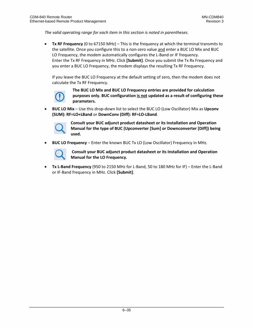
CDM-840 Remote Router MN-CDM840 Ethernet-based Remote Product Management Revision 3
6–35
The valid operating range for each item in this section is noted in parentheses. • Tx RF Frequency (0 to 67150 MHz) – This is the frequency at which the terminal transmits to
the satellite. Once you configure this to a non-zero value and enter a BUC LO Mix and BUC LO Frequency, the modem automatically configures the L-Band or IF frequency. Enter the Tx RF Frequency in MHz. Click [Submit]. Once you submit the Tx Rx Frequency and you enter a BUC LO Frequency, the modem displays the resulting Tx RF Frequency.
If you leave the BUC LO Frequency at the default setting of zero, then the modem does not calculate the Tx RF Frequency.
The BUC LO Mix and BUC LO Frequency entries are provided for calculation purposes only. BUC configuration is not updated as a result of configuring these parameters.
• BUC LO Mix – Use this drop-down list to select the BUC LO (Low Oscillator) Mix as Upconv (SUM): RF=LO+LBand or DownConv (Diff): RF=LO-LBand.
Consult your BUC adjunct product datasheet or its Installation and Operation Manual for the type of BUC (Upconverter [Sum] or Downconverter [Diff]) being used.
• BUC LO Frequency – Enter the known BUC Tx LO (Low Oscillator) Frequency in MHz.
Consult your BUC adjunct product datasheet or its Installation and Operation Manual for the LO Frequency.
• Tx L-Band Frequency (950 to 2150 MHz for L-Band, 50 to 180 MHz for IF) – Enter the L-Band or IF-Band frequency in MHz. Click [Submit].
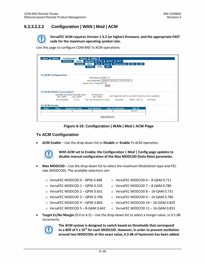
CDM-840 Remote Router MN-CDM840 Ethernet-based Remote Product Management Revision 3
6–36
6.3.3.2.2.2 Configuration | WAN | Mod | ACM
VersaFEC ACM requires Version 1.3.2 (or higher) firmware, and the appropriate FAST code for the maximum operating symbol rate.
Use this page to configure CDM-840 Tx ACM operations.
Figure 6-19. Configuration | WAN | Mod | ACM Page
Tx ACM Configuration
• ACM Enable – Use the drop-down list to Disable or Enable Tx ACM operation.
With ACM set to Enable, the Configuration | Mod | Config page updates to disable manual configuration of the Max MODCOD (Data Rate) parameter.
• Max MODCOD – Use the drop-down list to select the maximum Modulation type and FEC
rate (MODCOD). The available selections are: o VersaFEC MODCOD 0 – BPSK 0.488 o VersaFEC MODCOD 6 – 8-QAM 0.711 o VersaFEC MODCOD 1 – QPSK 0.533 o VersaFEC MODCOD 7 – 8-QAM 0.780 o VersaFEC MODCOD 2 – QPSK 0.631 o VersaFEC MODCOD 8 – 16-QAM 0.731 o VersaFEC MODCOD 3 – QPSK 0.706 o VersaFEC MODCOD 9 – 16-QAM 0.780 o VersaFEC MODCOD 4 – QPSK 0.803 o VersaFEC MODCOD 10 – 16-QAM 0.829 o VersaFEC MODCOD 5 – 8-QAM 0.642 o VersaFEC MODCOD 11 – 16-QAM 0.853
• Target Es/No Margin (0.0 to 4.5) – Use the drop-down list to select a margin value, in 0.5 dB increments.
The ACM system is designed to switch based on thresholds that correspond to a BER of 5 x 10⁻⁸ for each MODCOD. However, in order to prevent oscillation around two MODCODs at this exact value, 0.3 dB of hysteresis has been added.

CDM-840 Remote Router MN-CDM840 Ethernet-based Remote Product Management Revision 3
6–37
Click [Submit] to save.
Tx ACM Status (List all 880s)
From left to right:
Column Description Seconds since last LQRM Amount of time (in seconds) since an LQRM (Link Quality Report Message)
message was received from the associated CDD-880 Multi Receiver Router. Max Seconds since last LQRM Maximum amount of time since the last LQRM message was received. IP Source of last LQRM The source IP Address from where the last LQRM message was received. Last Reported Es/No Es/No value received in the last LQRM message. Current MODCOD Currently selected MODCOD. Current DataRate Current data rate based on current symbol rate and MODCOD.
Click the List all 880s hyperlink in the section header to display the CDD-880 Multi Receiver Routers incorporated into the active Advanced VSAT Network. The page will update to display this information:
From left to right:
Column Description Index The recognized CDD-880 is automatically assigned this internal index number. IP The source IP Address of the CDD-880. Current State Displays the state as Dead, Active, or Recovery. Last Reported Es/No Es/No value received in the CDD-880’s last LQRM message. Max Seconds Since last LQRM Maximum amount of time since the last LQRM message was received from
the CDD-880. Click the Configuration | WAN | Mod | ACM page tab to resume use of the HTTP Interface.
Tx ACM Events
In addition to the date- and time-stamp assigned for each event, information is presented in this read-only section as follows (from left to right):
Column Description Reported Es/No Es/No value. New MODCOD Newly selected MODCOD. New Tx DataRate New data rate based on new MODCOD and current symbol rate.
Click [Clear ACM Events] to clear all ACM statistics from the buffer.

CDM-840 Remote Router MN-CDM840 Ethernet-based Remote Product Management Revision 3
6–38
6.3.3.2.2.3 Configuration | WAN | Mod | DPC
• See adjunct CEFD publication VMS v3.x.x VIPERSAT Management System User Guide (CEFD P/N MN/22156)
• Appendix M. VMS DPC (DYNAMIC POWER CONTROL)
DPC is a selectable software feature operating independently on CDM-840s exchanging a UDP message between the receiving unit (where the signal quality is being measured) and the transmitting unit (where the power level is to be adjusted). This message contains link quality status, which is directed to the transmit site on timed intervals, updating the link state. Use this page to configure and monitor CDM-840 Tx Dynamic Power Control operations.
Figure 6-20. Configuration | WAN | Mod | DPC Page
Tx Dynamic Power Control (DPC) Configuration
• DPC Enable – Use the drop-down list to select Disabled or Enabled.
• Maximum Data Rate (16 kbps to 15.35 Mbps) – Enter a maximum date rate value.
• Terminal Maximum Power – Enter a value, in dBm.
• Tx Power Margin (0 to 40) – Enter a value, in dB. Click [Submit] to save.

CDM-840 Remote Router MN-CDM840 Ethernet-based Remote Product Management Revision 3
6–39
• Rated Maximum Power (read-only) – This displays the highest value that DPC will raise the power to during normal operation. This value is calculated from the references, Maximum Data Rate, and Tx Power Margin. o Click [Recalculate Max Power] to recalculate the Rated Maximum Power whenever you
change the Tx Power Margin and/or the Maximum Data Rate.
o Click [Reset Max Power] to set the Maximum Power to an invalid value. Use this setting when recalibrating references, when the previous settings do not allow DPC to reach the target Es/No.
o Click [Reset All Parameters to Factory Default] to completely disable DPC, remove the references, and to return all settings to the factory default.
Tx Dynamic Power Control (DPC) Status
Once reference calibration is complete, this section provides information on the ongoing DPC state. Each received LQRM updates this status section; any changes to power are noted between Target Es/No and Current DPC Delta. After the targeting of reference calibration, the DPC Delta is zeroed, and any +/- offset from this point indicates power changes due to link quality variations.
Depending on symbol rate, small rates will have variations up to ±.5 dB, even during clear-sky conditions.
Item Description Current Beam offset Current Beam offset is modified in a roam configuration, and any +/- offset
from zero either adds or subtracts from the margin or terminal maximum power backoff during a beam contour variation.
Target Es/No Target Es/No is calculated from maximum MODCOD and will remain constant unless changed.
Last Es/No Received This most recent reported value may change depending on link conditions. Current DPC Delta This represents the Adaptive Control Loop (ACL) change in power compared
to the set reference, which can increase to margin or terminal maximum power. Any decrease has the full remaining range down to -40 dBm of modulator’s output.
Time since last LQRM This is the time, in seconds, from the last power report received. Under normal conditions, the status updates every 60 seconds.
Power Reference
Click [Set Reference] to place the system into a calibration mode. Selecting this adjusts the Tx Power to achieve a BER of 10-8, and then stores this value along with the Reference MODCOD and Reference Symbol Rate. You may use these three Power Reference values to calculate an equivalent power for any MODCOD/Data Rate combination.

CDM-840 Remote Router MN-CDM840 Ethernet-based Remote Product Management Revision 3
6–40
6.3.3.2.3 Configuration | WAN | QoS (Quality of Service)
Appendix J. RETURN GROUP QOS (QUALITY OF SERVICE)
Figure 6-21 shows the appearance of this page when QoS is disabled (i.e., use the QoS Control Mode drop-down list, available in the Add/Change/Delete Group section of this page, to select Off, and then click [Submit]). The top portion of the QoS page provides common functionality for all QoS modes. The bottom portion of this page changes depending on the active QoS Mode. All commonality / differences in page appearance between QoS Modes is noted accordingly.
Comtech EF Data strongly recommends that you do NOT operate the CDM-840 with QoS Control Mode = Off. When QoS Control Mode = Off there is no traffic shaping or filtering. All data coming into the modem will be sent to the WAN as it is received, in the order it was received, for so long as the WAN can support the packet/frame and data rate of the incoming traffic. If there is not enough WAN capacity to support the incoming traffic, packets or frames are tail-dropped as they overflow the internal buffer.
Figure 6-21. Configuration | WAN | QoS Page (QoS Control Mode = Off)

CDM-840 Remote Router MN-CDM840 Ethernet-based Remote Product Management Revision 3
6–41
6.3.3.2.3.1 Page Functionality Common for all QoS Control Modes
The page content that follows is available in all QoS Modes.
You may click the (to QoS Statistic page) hyperlink, located at the top of the page, to view operational statistics on the Status | Statistics | QoS page (Sect. 6.3.4.1.4).
Add/Change/Delete Group
Use the top row text boxes, drop-down lists, and action button to Add (create) a QoS Group. The middle row allows you to Change (edit) the currently selected group. The bottom row allows you to Delete any available group other than the Default Group.
• Add a group – Use the top row text boxes to create and add a group. Click [Add] to create
the rule. From left to right (where applicable):
Column Description Index This is the internal index number for the group. This number increments or
decrements automatically as you add or delete groups. Name This is the name assigned to the group. The name you create must be 20
characters or less, and it must be unique across all groups. CIR (kbps) This is the Committed Information Rate for the group. The QoS Manager will try to
guarantee this date rate for all traffic that matches this group. MIR (kbps) This is the Maximum Information Rate for the group. The QoS Manager will not
allow traffic that matches this group to send more than this data rate. Mode When adding a new group or modifying an existing group, use the drop-down list to
select a QoS Mode of operation: • Off – This mode disables QoS. With QoS Control Mode = Off, the “Per Group”
add/deleted/edit tables sections of this page are replaced with the message “QoS Mode is Off.”
• DiffServ – This mode allows the CDM-840 to operate in Differentiated Services Mode to make it fully compliant to the Differentiated Services QoS RFC (Request For Comments) standards.
• Max/Pri – This mode provides multi-level traffic prioritization with the ability to limit maximum traffic per priority class.
• Min/Max – This mode provides a Committed Information Rate (CIR) to each user-defined class of traffic with the ability to allow a higher burstable rate depending on availability.
• Pri-Weighted – Weighting is used to drain traffic having the same Priority Level.

CDM-840 Remote Router MN-CDM840 Ethernet-based Remote Product Management Revision 3
6–42
• Change (modify) an existing group – Use the middle row text boxes to make changes to the active Index (group). Click [Change] to save. The Group Table will update accordingly.
• Delete an existing group – Use the bottom row text box to enter an Index (group) number.
Click [Delete]. Upon deletion, the table index automatically decrements to the next available number.
About the Default Group – This group will always exist and cannot be removed. The Default (QoS) Group has the following characteristics: • The Default Group is always serviced after the CIR and MIR for user-defined QoS groups
have been serviced (i.e., what is left over). The Default Group should not be used to reserve bandwidth.
• The CIR for the Default Group is forced to 0kbps.
• The MIR for the Default Group is forced to the Maximum.
• If a packet does not match one of the user-defined subnets associated with a QoS Group, the packet will be put into the Default Group.
• The Default Group contains all of the discovered Remote Sites. This means that if a matching Subnet is not found for a User-defined QoS Group, the Default (QoS) Group will be used and Outbound ACM will function as expected.
Group Table
This table displays the active QoS groups. See the table under “Add/Change/Delete Group” for detailed descriptions for each column. When more than one group is available, click Select to set that group as the active operational configuration. The page refreshes automatically. If only a single group exists, the page appearance defaults to display that group in all tables.
Add/Delete Per Group Attribute
When more than one group is created, use the controls in this section to select and configure an attribute:

CDM-840 Remote Router MN-CDM840 Ethernet-based Remote Product Management Revision 3
6–43
• Click VLAN to configure a VLAN ID assigned to the group. All traffic with the configured VLAN ID will be routed through the QoS Group. If more than one QoS Group has the same VLAN ID, then the subnet will be used to match the packet to the correct QoS Group.
The system Working Mode must be in BPM Mode in order to use the VLAN ID to match packets to a QoS Group.
• Click Subnet to configure a subnet assigned to the group. All traffic within the configured subnet will be routed through this QoS Group. If the QoS Group subnets should overlap, then the first QoS Group will be used for traffic.
To manage attributes: • Add an attribute – Use the top row text boxes to enter the attribute (i.e., the VLAN ID or
Subnet IP/Mask). Click [Add] to create the attribute.
• Delete an existing attribute – Enter an Index (attribute) number in the text box. Click [Delete] to execute removal of that attribute. The Attributes table will update accordingly.
Note the following: VLAN Attributes Table (from left to right):
Column Description Index This is the internal index number for the attribute. This number increments or
decrements automatically as you add or delete attributes. Type VLAN is the only available attribute. Value This is the assigned VLAN ID. Valid values are from 2 to 4095.
Subnet Attributes Table (from left to right):
Column Description Index This is the internal index number for the attribute. This number increments or
decrements automatically as you add or delete attributes. Type Subnet is the only available attribute. Value This is the assigned subnet, in xxx.xxx.xxx.xxx/yy format.
The Attributes table entries are displayed based on which traffic has matched to this QoS Group. The user-defined subnets entered into the QoS page need to be equal to or a superset of any of the routes from the remotes – i.e., there must be no overlaps. The user-defined VLAN ID must be an exact match. The examples that follow illustrate how the locally attached subnets associated with each Ethernet will be reported as routes, unless the Management IP address has not been changed; in which case, it will ignore that value.
Example #1 QoS Subnet 10.1.1.0/24 Remote Management IP Address 192.168.1.1 Remote’s Reported Routes 10.1.1.0/27 Result Remote 192.168.1.1 will be added when traffic to that remote is sent
through the CTOG-250

CDM-840 Remote Router MN-CDM840 Ethernet-based Remote Product Management Revision 3
6–44
Example #2 QoS Subnet 10.1.0.0/16 Remote 1 Management IP Address 192.168.1.1 Remote 1 Reported Routes 10.1.1.0/27 Remote 2 Management IP Address 192.168.1.1 Remote 2 Reported Routes 10.1.2.0/24 Result Remote 192.168.1.1 and 192.168.2.1 will be added
Example #3 QoS Subnet 10.1.2.0/24 Remote 1 Management IP Address 192.168.1.1 Remote 1 Reported Routes 10.1.2.0/23 Result Remote 192.168.1.1 will NOT be added because the 10.1.2.0/23 route
is not completely "covered" by the QoS Subnet.
Example #4 QoS VLAN ID 1000 Packet Format Packet #1 VLAN ID = 1000
Packet #2 No VLAN Packet #3 VLAN ID = 1001
Result Packet #1 will go through the QoS Group and cause the Remote ID for that Remote to be added to the Remote Sites list. Packet #2 and Packet #3 do not match and will either go to another QoS Group or fall to the Default Group.
6.3.3.2.3.2 Page Functionality Specific to Active QoS Mode
DiffServ (Differentiated Services) Rules Table
This table is accessible only when QoS Control Mode = DiffServ.

CDM-840 Remote Router MN-CDM840 Ethernet-based Remote Product Management Revision 3
6–45
When QoS Control Mode = DiffServ, you have the option of configuring attributes for each group (the acceptable ranges for each parameter are shown in brackets). Note the following (from left to right):
Column Description Index The automatically assigned specific rule internal index number is identified here. Priority IP traffic is prioritized based upon the DSCP (DiffServ Code Points) Class Selector
Precedence. Per-Hop Behavior (PHB) This is the traffic class that determines how packets will be forwarded. Codepoint (DSCP) This is the Codepoint value in the Type of Service (ToS) byte of the IP header. Service Rate (kbps) The minimum bandwidth is served first among the Assured Forwarding (ASFD) classes
in case of bandwidth availability, once Class Selector 7 through Class Selected 1 have been serviced.
Drop Precedences ASFD Class 4 through 1 Code Points (b100xx0, b011xx0, b010xx0, and b001xx0) carry the drop precedence value (xx). In case of network congestion, a Weighted Random Early Detection (WRED) congestion avoidance algorithm is imposed on these queues to drop the packets randomly rather than ‘tail drop.’
The ASFD classes all take Priority 8 instead of their corresponding class priorities (i.e., 1 through 4) to provide “Service Rate (kbps)” among all ASFD classes.
• Low Drop Precedence (% full) [100] – In case of congestion, the WRED is applied after the queue depth exceeds the configured percentage value assigned for the Drop Precedence value b001.
• Med. Drop Precedence (%full) [20–90] – In case of congestion, the WRED is applied after the queue depth exceeds the configured percentage value assigned for the Drop Precedence value b010.
• High Drop Precedence (% full)) [10-80] – In case of congestion, the WRED is applied after the queue depth exceeds the configured percentage value assigned for the Drop Precedence value b011.
Make sure that: High Drop Precedence value < Med. Drop value < Low Drop value.
Click [Submit] to save.
The page sections that follow are accessible only when QoS Control Mode = Max/Pri, Min/Max, or Pri-Weighted.
Add/Delete Per Group QoS Rule
The appearance of this table varies depending on your active QoS Control Mode. Examples are as follows: When QoS Control Mode = Max/Pri:

CDM-840 Remote Router MN-CDM840 Ethernet-based Remote Product Management Revision 3
6–46
When QoS Control Mode = Min/Max:
When QoS Control Mode = Pri-Weighted:
• Add a Rule – Enter your desired parameters as needed, and click [Add Rule] to add the rule to the Per Group QoS Rule table. Upon entry, the table index automatically increments to the next available number. Note the following (from left to right):
Column Description Name This is the name assigned to the group rule. The name you create must be 20 characters
or less, and it must be unique across all groups. VLAN Min Enter a single VLAN ID as the minimum filter value. . VLAN Max Enter a single VLAN ID as the maximum filter value. TOS Type Of Service bits include a six-bit Differentiated Services Code Point (DSCP) and a
two-bit Explicit Congestion Notification (ECN) field: • Enter an explicit Code Point match. • Enter the wildcard entry of 255 so that all values trigger true.
Application Use the drop-down list to select the application as UDP, TCP, ICMP, RTP, RTP-VOICE, RTP-VIDEO, RTPS, FTP, HTTP, TELNET, SMTP, SNMP, or All-IP.
Src IP/Msk Enter a Source IP Address/Mask in the form XXX.XXX.XXX.XXX/YY. Dst IP/Msk Enter a Destination IP Address/Mask in the form XXX.XXX.XXX.XXX/YY. Min Src Port You should specify the Min / Max Source / Destination Ports only if you are aware of
the port usage of the desired protocol or application. There are well-known ports for various protocols, but often only the ‘command’ messaging is transacted on these ports and the ‘data’ is transferred through a negotiated port.
Max Src Prt Min Dst Port Max Dst Port Priority (Max/Pri and Pri-Weighted modes only) Use the drop-down list to assign a Priority Level
from 1 to 8 for each flow: • The IP Module classifies each packet that is to be forwarded over the satellite; the
packet then has a Priority assigned according to the defined QoS Rules; • Any latency critical traffic such as VoIP/RTP should always be assigned Priority 1; • Priority 1 packets are forwarded immediately; Priority 2 packets are forwarded as soon
as there are no Priority 1 packets in the Queue; and so on; • Any packet that does not meet a QoS Rule is assigned to the Default Rule and is
assigned a Priority of 9.
Weight (Pri-Weighted mode only) Enter a weight from 1 to 9. Weighting is used to drain traffic having the same Priority Level (“Max/Pri” mode) after the minimum bandwidth is met (“Min BW”). The larger the number, the higher the weight.
Min BW (Min/Max and Pri-Weighted modes only) Assign a value to limit the flow to this minimum utilized bandwidth; otherwise, you may select the default of no bandwidth restriction.
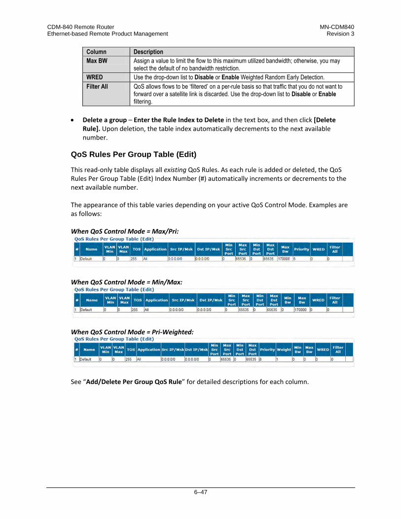
CDM-840 Remote Router MN-CDM840 Ethernet-based Remote Product Management Revision 3
6–47
Column Description Max BW Assign a value to limit the flow to this maximum utilized bandwidth; otherwise, you may
select the default of no bandwidth restriction. WRED Use the drop-down list to Disable or Enable Weighted Random Early Detection. Filter All QoS allows flows to be ‘filtered’ on a per-rule basis so that traffic that you do not want to
forward over a satellite link is discarded. Use the drop-down list to Disable or Enable filtering.
• Delete a group – Enter the Rule Index to Delete in the text box, and then click [Delete
Rule]. Upon deletion, the table index automatically decrements to the next available number.
QoS Rules Per Group Table (Edit)
This read-only table displays all existing QoS Rules. As each rule is added or deleted, the QoS Rules Per Group Table (Edit) Index Number (#) automatically increments or decrements to the next available number. The appearance of this table varies depending on your active QoS Control Mode. Examples are as follows: When QoS Control Mode = Max/Pri:
When QoS Control Mode = Min/Max:
When QoS Control Mode = Pri-Weighted:
See “Add/Delete Per Group QoS Rule” for detailed descriptions for each column.

CDM-840 Remote Router MN-CDM840 Ethernet-based Remote Product Management Revision 3
6–48
6.3.3.2.4 Configuration | WAN | Label
Use this page to assign up to four Generic Stream Encapsulation (GSE) WAN labels.
Figure 6-22. Configuration | WAN | Label Page
Receive WAN Labels
Edit the Label 1 through Label 4 text boxes to suit. Each label has a valid range of 1 to 2047.
The assigned Receive WAN Labels must match the WAN Labels assigned on the CTOG-250 Route Table. Note that the preferred method of operation (as required for ACM/VCM Operation) is to first configure a unique WAN Label in Entry #1 for each CDM-840 across the network, and then enable CDRP on the CTOG-250. The associated Route to WAN Label will be automatically updated and maintained.
Click [Submit] to save.

CDM-840 Remote Router MN-CDM840 Ethernet-based Remote Product Management Revision 3
6–49
6.3.3.2.5 Configuration | WAN | Compression
Use this page to configure the Payload and Header Compression feature, if enabled.
Figure 6-23. Configuration | WAN | Compression Page
Click the (Link to Compression Statistic page) hyperlink to access the Status | Statistics | Compression page (Sect. 6.3.4.1.3).
Refresh Rates
Enter each refresh rate, from 1 to 600 packets or 1 second (whichever comes first). From left to right:
Feature Description Header Compression for UDP User Datagram Protocol refresh rate Header Compression for RTP Real Time Protocol refresh rate Header Compression for all others Default protocol refresh rate Payload Compression Payload Compression refresh rate
Set the desired rates. Click [Submit] to save.
Bridge Point-to-Multipoint (BPM) Mode Configuration
Use the drop-down lists to Enable or Disable Payload and Header Compression for all of the transmitted packets when operating in Bridge Point-to-Multipoint (BPM) Mode. Click [Submit] to save.
In Managed Switch Mode, the selected Compression modes apply to all traffic.
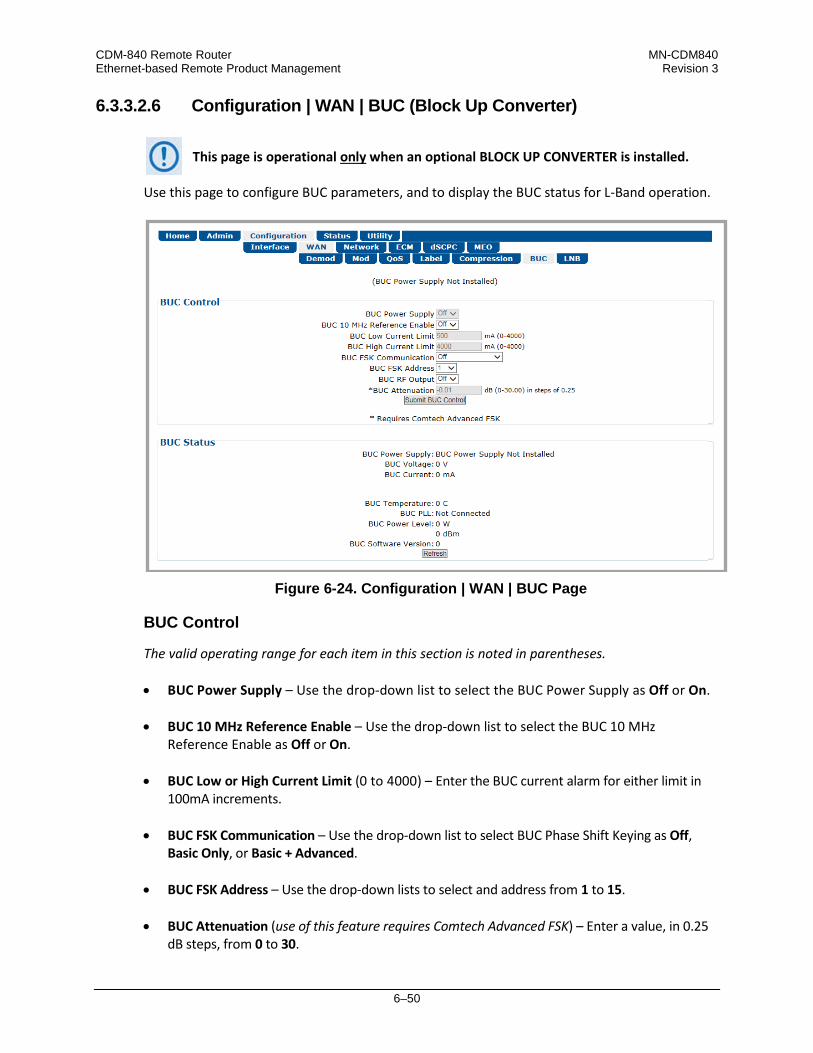
CDM-840 Remote Router MN-CDM840 Ethernet-based Remote Product Management Revision 3
6–50
6.3.3.2.6 Configuration | WAN | BUC (Block Up Converter)
This page is operational only when an optional BLOCK UP CONVERTER is installed.
Use this page to configure BUC parameters, and to display the BUC status for L-Band operation.
Figure 6-24. Configuration | WAN | BUC Page
BUC Control
The valid operating range for each item in this section is noted in parentheses. • BUC Power Supply – Use the drop-down list to select the BUC Power Supply as Off or On. • BUC 10 MHz Reference Enable – Use the drop-down list to select the BUC 10 MHz
Reference Enable as Off or On. • BUC Low or High Current Limit (0 to 4000) – Enter the BUC current alarm for either limit in
100mA increments. • BUC FSK Communication – Use the drop-down list to select BUC Phase Shift Keying as Off,
Basic Only, or Basic + Advanced. • BUC FSK Address – Use the drop-down lists to select and address from 1 to 15. • BUC Attenuation (use of this feature requires Comtech Advanced FSK) – Enter a value, in 0.25
dB steps, from 0 to 30.

CDM-840 Remote Router MN-CDM840 Ethernet-based Remote Product Management Revision 3
6–51
Click [Submit BUC Control] to save.
BUC Status
When the presence of BUC Power Supply is detected, it is acknowledged here and its voltage and current information is continuously monitored and is provided on a read-only basis: • BUC Power Supply
• BUC Voltage (V)
• BUC Current (mA)
• BUC Temperature (degrees Celsius)
• BUC PLL (Phase Lock Loop)
• BUC Power Level (W / dBm)
• BUC Software Version Click [Refresh] to update this section with its latest available statistics.

CDM-840 Remote Router MN-CDM840 Ethernet-based Remote Product Management Revision 3
6–52
6.3.3.2.7 Configuration | WAN | LNB (Low Noise Block Down Converter)
This page is operational only when an optional LOW-NOISE BLOCK DOWN CONVERTER is installed.
Use this page to configure LNB parameters, and to display the LNB status for L-Band operation.
Figure 6-25. Configuration | WAN | LNB Page
LNB Control
The valid operating range for each item in this section is noted in parentheses. • LNB DC Power – Use the drop-down list to select the power as Off, 13V, 18V, or 24V. • LNB Reference Enable – Use the drop-down list to Enable or Disable the LNB Reference. • LNB Current Threshold (Low and High) (0 to 500) – Enter a value, in mA, for either function. Click [Submit LNB Controls] to save.
LNB Status
This read-only section provides the LNB Current (mA) and LNB Voltage (V) information. Click [Refresh] to update this section with its latest available statistics.

CDM-840 Remote Router MN-CDM840 Ethernet-based Remote Product Management Revision 3
6–53
6.3.3.3 Configuration | Network Pages
Use the Network pages to configure network-based operating parameters. Click the Routing, ARP, Working Mode, or DNS tab to continue.
6.3.3.3.1 Configuration | Network | Routing Pages
Click the Routes, IGMP, or DHCP tab to continue.
6.3.3.3.1.1 Configuration | Network | Routing | Routes
When operating a network in Bridge Point-to-Multipoint (BPM) mode, user traffic will pass through the various traffic ports; however, the management of the network is required to be through the routed Management Network.
Use this page to enter static routes for IP traffic over the satellite or to another device on the local LAN.
Figure 6-26. Configuration | Network | Routing | Routes Page
Add New Route
Use this section to directly add a route. From left to right:
Column Description Index This is the read-only internal index number for the route. This number increments or
decrements automatically as you add or delete routes. Description This label helps to maintain the network. The name you create must be 20 characters or less,
and it must be unique across all routes. Dest. IP/Mask Enter a Destination IP Address/Mask in the form XXX.XXX.XXX.XXX/YY. Intfc. Use the drop-down list to select the Interface as toWAN or toLAN. Next Hop IP Enter the desired Next Hop IP Address for toLAN routes. Note that no Next Hop entry is
needed for toWAN routes.

CDM-840 Remote Router MN-CDM840 Ethernet-based Remote Product Management Revision 3
6–54
Column Description Header Comp. Use the drop-down list to Disable or Enable Header Compression operation. Payload Comp. Use the drop-down list to Disable or Enable Payload Compression operation.
Click [Add Entry] when done. The index automatically increments to the next available number when the new route is added.
When in Router Mode, the CDM-840 will not transmit a multicast address in the Internet control range (224.0.0.0 to 224.0.1.255). It filters the packets.
Delete Route
Enter Route Index to Delete. Click [Delete Entry] to delete the specified route entry from the route table. Upon deletion, the Route Table index number automatically decrements to the next available number.
Route Table (Edit)
Use the text boxes and drop-down lists to edit all current Route Table entries, as described previously for the Add New Route section. Click [Submit Changes] to save. The Route Table entries will update accordingly.

CDM-840 Remote Router MN-CDM840 Ethernet-based Remote Product Management Revision 3
6–55
6.3.3.3.1.2 Configuration | Network | Routing | IGMP
When operating a network in Bridge Point-to-Multipoint (BPM) mode, user traffic will pass through the various traffic ports; however, the management of the network is required to be through the routed Management Network.
IGMP (Internet Group Management Protocol), when enabled, responds to IGMP queries for the configured multicast routes on the transmit side and generates IGMP queries on the receive side. If there are no active IGMP receivers on the LAN, it stops forwarding the multicast traffic (received from the satellite) to the LAN. Use this page to enable IGMP for configured multicast routes.
Figure 6-27. Configuration | Network | Routing | IGMP Page
IGMP
WAN to traffic port multicast traffic – Use the drop-down list to set operation as Use IGMP or Forward All Multicast.
IGMP Configuration
The valid operating ranges are provided in this section in parentheses, where applicable. • Version – Use the drop-down list to select IGMPv1, IGMPv2, or IGMPv3.
• Last Member Query Interval (1 to 25) – Enter a value, in seconds. The default is 1 second.
This is the maximum response time inserted into group-specific queries that are set in response to Leave Group messages, and is also amount of time between group-specific query messages. This value may be tuned to modify the "leave latency" of the network; a reduced value results in reduced time to detect the loss of the last member of a group.
CDM-840 Remote Router MN-CDM840 Ethernet-based Remote Product Management Revision 3
6–56
• Query Interval (1 to 60) – Enter a value, in seconds. The default is 1 second. This is the interval between general queries sent by the unit. By varying the query interval, the administrator may tune the number of IGMP messages on the subnet; note that larger numbers cause the IGMP queries to be sent less often.
• Query Response Interval (1 to 25) – This is the maximum response time inserted into the periodic general queries. By varying the Query Response Interval, the administrator may tune the “burstiness” of IGMP messages on the subnet; note that larger values make the traffic less “bursty” as host responses are spread out over a large interval.
The number of seconds assigned to the Query Response Interval must be less than the Query Interval.
Click [Submit] to save.
IGMP Table
This read-only table lists the IGMP Groups that are active on the unit. This allows you to determine which services are being used and the minimum time before a service will be terminated. Click [Refresh] to update this section with its latest available statistics.
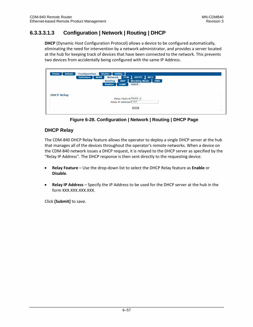
CDM-840 Remote Router MN-CDM840 Ethernet-based Remote Product Management Revision 3
6–57
6.3.3.3.1.3 Configuration | Network | Routing | DHCP
DHCP (Dynamic Host Configuration Protocol) allows a device to be configured automatically, eliminating the need for intervention by a network administrator, and provides a server located at the hub for keeping track of devices that have been connected to the network. This prevents two devices from accidentally being configured with the same IP Address.
Figure 6-28. Configuration | Network | Routing | DHCP Page
DHCP Relay
The CDM-840 DHCP Relay feature allows the operator to deploy a single DHCP server at the hub that manages all of the devices throughout the operator's remote networks. When a device on the CDM-840 network issues a DHCP request, it is relayed to the DHCP server as specified by the "Relay IP Address". The DHCP response is then sent directly to the requesting device. • Relay Feature – Use the drop-down list to select the DHCP Relay feature as Enable or
Disable.
• Relay IP Address – Specify the IP Address to be used for the DHCP server at the hub in the form XXX.XXX.XXX.XXX.
Click [Submit] to save.

CDM-840 Remote Router MN-CDM840 Ethernet-based Remote Product Management Revision 3
6–58
6.3.3.3.2 Configuration | Network | ARP
Use this page to configure the CDM-840 ARP (Address Resolution Protocol) parameters.
Figure 6-29. Configuration | ARP Page
Add Static ARP
Enter the desired IP and MAC addresses. Click [Add Entry] when done. The Index column automatically increments to the next available number when the specified static ARP entry is added to the ARP Table.
Comtech EF Data recommends that you do not add Static ARP entries. Dynamic ARPs should function as expected under normal operation. You should use Static ARP entries only when it has been demonstrated that a connected networking device does not respond to ARP as expected.
Delete Static ARP
Enter the Entry Index to Delete. Click [Delete Entry] to delete the specified entry index from the ARP Table. Upon deletion, the ARP Table index number automatically decrements to the next available number.
Flush Dynamic ARP
Click [Flush Dynamic ARP] to delete all dynamically-learned ARP entries.
ARP Table (Edit)
This section displays all current Static and Dynamic ARP entries, and allows to user to directly edit the current Static ARP entries. From left to right:

CDM-840 Remote Router MN-CDM840 Ethernet-based Remote Product Management Revision 3
6–59
Column Description Index This is the read-only internal index number for the ARP entry. This number increments or
decrements automatically as you add or delete entries. IP Entry IP Address, format XXX.XXX.XXX.XXX. MAC Entry MAC Address, format YY:YY:YY:YY:YY. Type The read-only entry Type is listed here as Static or Dynamic and cannot be edited.
Click [Submit Changes] to save.
6.3.3.3.3 Configuration | Network | Working Mode
See Appendix E. BPM (BRIDGE POINT-TO-MULTIPOINT) OPERATION for more details on operating a network in BPM Mode.
Figure 6-30. Configuration | Network | Working Mode Page
Working Mode
Select the desired working mode: • In Router Mode, the traffic ports of the CTOG-250, CDD-880, and CDM-840 are configured
to function as a Router.
• In BPM Mode, all L2/L3/L4 protocols such as VLAN, MPLS, IPv6, OSPF, and BGP will flow through the network as they would through an off-the-shelf Ethernet Switch. The Advanced VSAT BPM feature makes the Advanced VSAT equipment appear as a “Sky Ethernet Switch”. This will allow for a greatly simplified network deployment.
Click [Submit] to save.

CDM-840 Remote Router MN-CDM840 Ethernet-based Remote Product Management Revision 3
6–60
6.3.3.3.4 Configuration | Network | DNS
DNS (Domain Name System) caching speeds up Internet access by eliminating subsequent queries over the satellite link. Use this page to manage DNS caching.
Figure 6-31. Configuration | Network | DNS Page
Note the following: • When the CDM-840 receives a DNS query at one of its Ethernet ports, a DNS cache lookup is
performed in the local DNS cache. If the entry is found, a DNS response message is immediately returned to the requesting entity with a time-to-live value of 10 seconds. If no match is found, the request packet is forwarded to the Hub.
• When a DNS response packet is received from the Hub, a check is made to see if the entry already exists in the cache. If it exists, the time-to-live for the entry is reset to 900 seconds (15 minutes). If it is a new entry, it is added to the cache with time-to-live set to 900 seconds (15 minutes).
• The local DNS cache is periodically cleaned by removing expired entries.
DNS Caching
Use the drop-down list to set DNS Caching as Disabled or Enabled. Click [Submit] to save.
DNS Cache Flush
Click [Flush] to clear the DNS Cache of all data.

CDM-840 Remote Router MN-CDM840 Ethernet-based Remote Product Management Revision 3
6–61
6.3.3.4 Configuration | ECM (Entry Channel Mode)
1) The Configuration | ECM page is operational only when the optional VIPERSAT MANAGEMENT SYSTEM (VMS) is installed and enabled.
2) ECM uses Demod 1 of the CDD-880 as the ALOHA channel.
• Appendix G. ECM (ENTRY CHANNEL MODE) • Appendix G. ENTRY CHANNEL MODE SWITCHING in the adjunct CEFD publication
VMS v3.x.x VIPERSAT Management System User Guide (CEFD P/N MN/22156) ECM (Entry Channel Mode) provides a method for remotes requiring dSCPC access channels to either enter the network initially or re-enter the network after a power or service outage. Use this page to configure ECM.
Figure 6-32. Configuration | ECM Page
ECM Remote Configuration
• Mode – Use the drop-down list to select operation as Disabled, Offline, Wait, or Online: Selection Description Disabled This disables ECM operation. Offline The remote will not transmit and remains in this standby mode until a new state is selected,
either locally or from the VMS. Application examples for this mode include COTM (Communications On The Move) or military maneuvers requiring radio silence conditions.
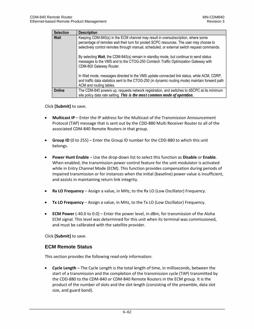
CDM-840 Remote Router MN-CDM840 Ethernet-based Remote Product Management Revision 3
6–62
Selection Description Wait Keeping CDM-840(s) in the ECM channel may result in oversubscription, where some
percentage of remotes wait their turn for pooled SCPC resources. The user may choose to selectively control remotes through manual, scheduled, or external switch request commands. By selecting Wait, the CDM-840(s) remain in standby mode, but continue to send status messages to the VMS and to the CTOG-250 Comtech Traffic Optimization Gateway with CDM-800 Gateway Router. In Wait mode, messages directed to the VMS update connected link status, while ACM, CDRP, and traffic data statistics sent to the CTOG-250 (in dynamic routing mode) maintain forward path ACM and routing tables.
Online The CDM-840 powers up, requests network registration, and switches to dSCPC at its minimum site policy data rate setting. This is the most common mode of operation.
Click [Submit] to save. • Multicast IP – Enter the IP address for the Multicast of the Transmission Announcement
Protocol (TAP) message that is sent out by the CDD-880 Multi Receiver Router to all of the associated CDM-840 Remote Routers in that group.
• Group ID (0 to 255) – Enter the Group ID number for the CDD-880 to which this unit belongs.
• Power Hunt Enable – Use the drop-down list to select this function as Disable or Enable.
When enabled, the transmission power control feature for the unit modulator is activated while in Entry Channel Mode (ECM). This function provides compensation during periods of impaired transmission or for instances when the initial (baseline) power value is insufficient, and assists in maintaining return link integrity.
• Rx LO Frequency – Assign a value, in MHz, to the Rx LO (Low Oscillator) Frequency. • Tx LO Frequency – Assign a value, in MHz, to the Tx LO (Low Oscillator) Frequency.
• ECM Power (-40.0 to 0.0) – Enter the power level, in dBm, for transmission of the Aloha
ECM signal. This level was determined for this unit when its terminal was commissioned, and must be calibrated with the satellite provider.
Click [Submit] to save.
ECM Remote Status
This section provides the following read-only information: • Cycle Length – The Cycle Length is the total length of time, in milliseconds, between the
start of a transmission and the completion of the transmission cycle (TAP) transmitted by the CDD-880 to the CDM-840 or CDM-840 Remote Routers in the ECM group. It is the product of the number of slots and the slot length (consisting of the preamble, data slot size, and guard band).

CDM-840 Remote Router MN-CDM840 Ethernet-based Remote Product Management Revision 3
6–63
• Aloha State – The Aloha State indicates the current state of this unit during the ECM cycle:
Unit State Description Idle Unit is not transmitting; either inactive or waiting for switching assignment. Active Unit is actively transmitting (probing) to the Hub for either registration or request for switching
to dSCPC. Switched Remote has successfully switched from ECM to dSCPC.
• Current Tap – Indicates current value of sequential progression of TAP message
transmission. Ranges from 0 to 255, then repeats. • Current Slot – The time slot number that has been assigned to this unit in the transmission
cycle for switching from ECM to dSCPC. • Home State Revert Timer – The time, in seconds, that must pass without receiving
communications from the HCC (Hub Channel Controller – i.e., Demod #1 on the CDD-880, the designated ECM controller) TAP message before this unit is reverted from dSCPC mode back to ECM to re-establish communications settings for receiving the TAP. This parameter is set in the VMS.
• Probing Duration – Amount of time, in seconds, that this unit has been transmitting to the
HCC to request registration and switchout. • Seconds Until Next Probe – The time period, in seconds, before this unit will again transmit
to the HCC.
ECM Tx Statistics
This section provides the following read-only information:
Row Description Total Count This is the total number of transmissions since the modem entered Entry
Channel Mode. Successes This is the number of successful (entire) transmissions received by the hub. Failures This is the number of incomplete transmissions that were detected by the hub. No Detect This is the number of transmissions that were undetected by the hub Last Status This displays the status of the most recent transmission as Success, Failure, or
No Detect. Seconds since last xmit This is the number of seconds since the last transmission, regardless of status.
Whenever the modem reverts from dSCPC to ECM, the statistics will clear.

CDM-840 Remote Router MN-CDM840 Ethernet-based Remote Product Management Revision 3
6–64
6.3.3.5 Configuration | dSCPC (Dynamic Single Carrier per Channel)
This page is operational only when the optional dSCPC FAST feature and VIPERSAT MANAGEMENT SYSTEM (VMS) is installed and enabled.
Use the optional dSCPC (Dynamic Single Carrier per Channel) FAST feature to enable dynamic allocation and sharing of bandwidth among users.
Figure 6-33. Configuration | dSCPC Page
Load Switching Configuration
The valid operating ranges for items in this section are provided in parentheses. • Mode – Use the drop-down list to select operation as Disabled or Enabled.
Click [Submit] to save.
• Step Up Threshold (0 to 100) – Enter the percentage of bandwidth use that will trigger a switch up from the present SCPC rate to a higher rate to ensure that there is sufficient bandwidth available for current conditions. Note that this value must be greater than the value specified for the SCPC Step Down Threshold. A typical setting for this parameter is 95%.
• Step Down Threshold (0 to 100) – Enter the percentage of bandwidth use that will trigger a
switch down from the present SCPC rate to a lower rate to ensure efficient bandwidth usage for current conditions. Note that this value must be less than the value specified for the SCPC Step Up Threshold. A typical setting for this parameter is 65%.
• Delay (1 to 50) – Enter the Switching Delay period, in seconds, to ensure that a premature
switch up or down in the SCPC rate does not occur due to a temporary rise or fall in traffic.

CDM-840 Remote Router MN-CDM840 Ethernet-based Remote Product Management Revision 3
6–65
• Excess Capacity (0 to 100) – Enter the Excess Capacity data rate percentage to be added to
the SCPC data rate. This setting makes additional bandwidth available for when demand arises while minimizing Step Up switching events.
ToS Switching Configuration
• Enable – Use the drop-down list to select operation as Disabled or Enabled.
• Max # of Sessions (per ToS Id) (1 to 127) – Allows setting a limit for the number of active sessions for a particular ToS switch type. Note that the overall limit for active sessions in the network is 127.
Click [Submit] to save.
(ToS Rules Table)
The valid operating range for each item in this section is noted in parentheses. From left to right:
Column Description Index The automatically-assigned specific rule internal index number is identified here. Name (1 to 20 characters) – Enter a text label for circuit identification. ID (1 to 63) – Enter an integer value for the ToS ID.
Type (64 to 254) – Enter an integer value for the Switch Type to inform the VMS what switching policy to use.
SCPC Data Rate (16 to 16000) Enter the desired data rate, in kbps, for this service type.
Timeout (0 to 60) Enter the timer setting, in seconds, for restoring the home state condition once data packet flow stops.
• Change (edit) a ToS Switching Configuration rule – Edit the information for the specific
indexed rule. Click [Change].
• Delete a ToS Switching Configuration rule – Click [Delete] to delete the specific indexed rule from the ToS Rules Table.
• Add a ToS Switching Configuration rule – Enter the information for the new rule. Click [Add
Entry]. The rule will be assigned to the next incremented index number, with [Change] and [Delete] functionality assigned to the new entry.

CDM-840 Remote Router MN-CDM840 Ethernet-based Remote Product Management Revision 3
6–66
6.3.4 Status Pages
The Status pages provide status, event logging, and operational statistics windows. Click the Statistics or Monitor tab to continue.
6.3.4.1 Status | Statistics Pages
Click the Traffic, Network, Compression, QoS, E1, or Trending tab to continue.
6.3.4.1.1 Status | Statistics | Traffic
Use this page to view read-only, abridged status windows pertaining to the basic operational statistics for the Ethernet, Modulator, and Demodulator traffic.
Figure 6-34. Status | Statistics | Traffic Page

CDM-840 Remote Router MN-CDM840 Ethernet-based Remote Product Management Revision 3
6–67
Statistics Control
Click [Clear Eth Stats], [Clear Mod Stats], [Clear Demod Stats], [Clear Drops (QoS Stats)], [Clear All Stats], or [Refresh]. From left to right:
Action Button Function [Clear Eth Stats] Click to clear entries from the Ethernet Statistics table. [Clear Mod Stats] Click to clear entries from the Mod Statistics table. [Clear Demod Stats] Click to clear entries from the Demod Statistics table. [Clear Drops (QoS Stats)] Click to clear the packets dropped in the Mod Statistics table. [Clear All Stats] Click to clear entries from all statistics tables on this page. [Refresh] Click to update the contents of all tables on this page.
Ethernet Statistics
Typical for either the FE (ETHERNET | MANAGEMENT | FE) or GE (ETHERNET | TRAFFIC | GE) ports, from left to right:
Interface Column Description FE GE
Total Packets Transmitted Total number of packets transmitted. Total Packets Received Total number of packets received. UC Packets Transmitted Unicast packets transmitted. UC Packets Received Unicast packets received. MC Packets Transmitted Multicast packets transmitted. MC Packets Received Multicast packets received. Current Tx Rate (kbps) Most recent transmitted data rate (in kilobits per second). Current Rx Rate (kbps) Most recently received data rate (in kilobits per second). Maximum Tx Rate (kbps) Peak transmitted data rate (in kilobits per second). Maximum RX Rate (kbps) Peak received data rate (in kilobits per second).
Mod Statistics
From left to right:
Column Description Packets Transmitted Packets transmitted. UC Packets Transmitted Unicast packets transmitted. MC Packets Transmitted Multicast packets transmitted. Packets Dropped Packets dropped. Current Tx Rate (pps) Most recently transmitted symbol rate (in packets per second). Current Tx Rate (kbps) Most recently transmitted symbol rate (in kilobits per second). Maximum Tx Rate (kbps) Peak transmitted symbol rate (in kilobits per second). Total Bytes Transmitted Total number of bytes transmitted.
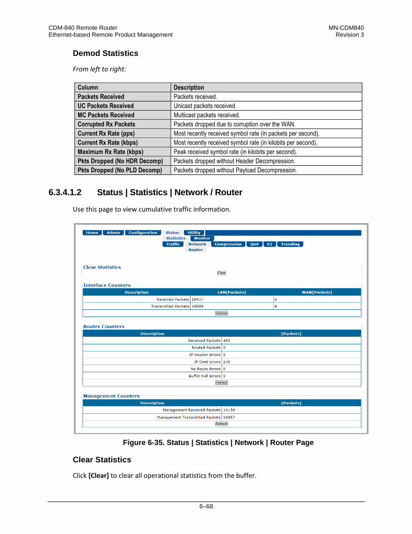
CDM-840 Remote Router MN-CDM840 Ethernet-based Remote Product Management Revision 3
6–68
Demod Statistics
From left to right:
Column Description Packets Received Packets received. UC Packets Received Unicast packets received. MC Packets Received Multicast packets received. Corrupted Rx Packets Packets dropped due to corruption over the WAN. Current Rx Rate (pps) Most recently received symbol rate (in packets per second). Current Rx Rate (kbps) Most recently received symbol rate (in kilobits per second). Maximum Rx Rate (kbps) Peak received symbol rate (in kilobits per second). Pkts Dropped (No HDR Decomp) Packets dropped without Header Decompression. Pkts Dropped (No PLD Decomp) Packets dropped without Payload Decompression.
6.3.4.1.2 Status | Statistics | Network / Router
Use this page to view cumulative traffic information.
Figure 6-35. Status | Statistics | Network | Router Page
Clear Statistics
Click [Clear] to clear all operational statistics from the buffer.
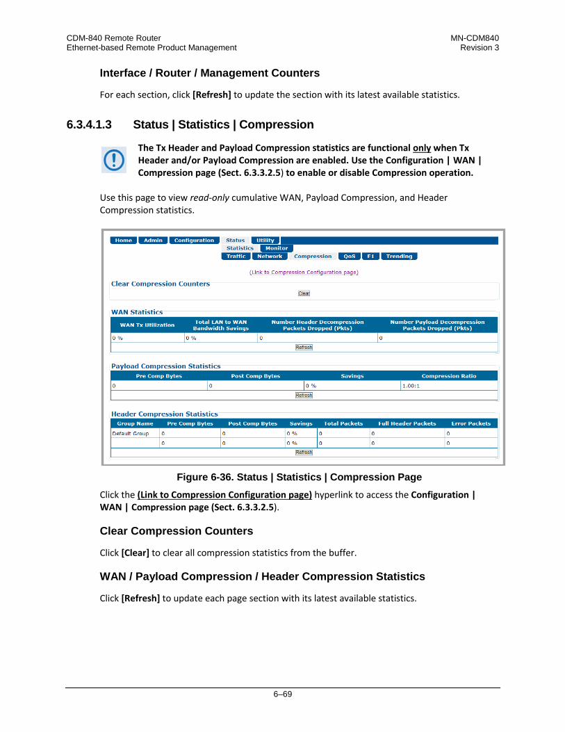
CDM-840 Remote Router MN-CDM840 Ethernet-based Remote Product Management Revision 3
6–69
Interface / Router / Management Counters
For each section, click [Refresh] to update the section with its latest available statistics.
6.3.4.1.3 Status | Statistics | Compression
The Tx Header and Payload Compression statistics are functional only when Tx Header and/or Payload Compression are enabled. Use the Configuration | WAN | Compression page (Sect. 6.3.3.2.5) to enable or disable Compression operation.
Use this page to view read-only cumulative WAN, Payload Compression, and Header Compression statistics.
Figure 6-36. Status | Statistics | Compression Page
Click the (Link to Compression Configuration page) hyperlink to access the Configuration | WAN | Compression page (Sect. 6.3.3.2.5).
Clear Compression Counters
Click [Clear] to clear all compression statistics from the buffer.
WAN / Payload Compression / Header Compression Statistics
Click [Refresh] to update each page section with its latest available statistics.
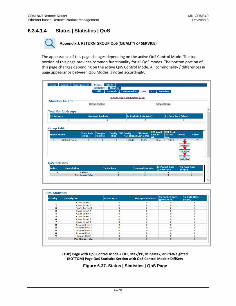
CDM-840 Remote Router MN-CDM840 Ethernet-based Remote Product Management Revision 3
6–70
6.3.4.1.4 Status | Statistics | QoS
Appendix J. RETURN GROUP QoS (QUALITY OF SERVICE)
The appearance of this page changes depending on the active QoS Control Mode. The top portion of this page provides common functionality for all QoS modes. The bottom portion of this page changes depending on the active QoS Control Mode. All commonality / differences in page appearance between QoS Modes is noted accordingly.
(TOP) Page with QoS Control Mode = OFF, Max/Pri, Min/Max, or Pri-Weighted (BOTTOM) Page QoS Statistics Section with QoS Control Mode = DiffServ
Figure 6-37. Status | Statistics | QoS Page

CDM-840 Remote Router MN-CDM840 Ethernet-based Remote Product Management Revision 3
6–71
6.3.4.1.4.1 Page Functionality Common for all QoS Control Modes
The page content that follows is available in all QoS Modes.
You may click the (to QoS Configuration page) hyperlink, located at the top of the page, to select a different QoS Mode or manage your QoS groups (Sect. 6.3.3.2.3).
Statistics Control
• Click [Clear All Counters] to clear the statistics buffers of all existing data.
• Click [Refresh Statistics] to update the statistics tables with the most recently reported statistics.
Total For All Groups
This table provides the cumulative tally of all QoS Groups for the number of Tx Packets, Dropped Packets, Tx Packet Rate, and Tx Data Rate.
Group Table
This table provides a cumulative tally of the active selected groups. Click Select to designate an active group – the row will automatically refresh with the group’s latest compiled operating statistics. From left to right:
Column Description Index This is the internal index number for the group. Name This is the unique name assigned to the group. Data Rate (kbps) This is the configured operating data rate (in kilobits per second). Dropped Packets This is the total number of packets dropped by the group. Config. CIR (kbps) This is the Committed Information Rate (in kilobits per second).as configured for
the group. Config. MIR (kbps) This is the Maximum Information Rate (in kilobits per second).as configured for
the group.
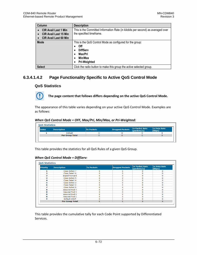
CDM-840 Remote Router MN-CDM840 Ethernet-based Remote Product Management Revision 3
6–72
Column Description • CIR Avail Last 1 Min • CIR Avail Last 15 Min • CIR Avail Last 60 Min
This is the Committed Information Rate (in kilobits per second) as averaged over the specified timeframe.
Mode This is the QoS Control Mode as configured for the group: • Off • DiffServ • Max/Pri • Min/Max • Pri-Weighted
Select Click the radio button to make this group the active selected group.
6.3.4.1.4.2 Page Functionality Specific to Active QoS Control Mode
QoS Statistics
The page content that follows differs depending on the active QoS Control Mode.
The appearance of this table varies depending on your active QoS Control Mode. Examples are as follows: When QoS Control Mode = OFF, Max/Pri, Min/Max, or Pri-Weighted:
This table provides the statistics for all QoS Rules of a given QoS Group. When QoS Control Mode = DiffServ:
This table provides the cumulative tally for each Code Point supported by Differentiated Services.

CDM-840 Remote Router MN-CDM840 Ethernet-based Remote Product Management Revision 3
6–73
6.3.4.1.5 Status | Statistics | E1 Pages (CDM-840 only)
Use these read-only pages to view cumulative CDM-840 E1 traffic information. Click the Transmit or Receive tab to continue.
6.3.4.1.5.1 Status | Statistics | E1 | Transmit
Figure 6-38. Status | Statistics | E1 | Transmit Page
E1 Transmit Statistics
From left to right:
“Description” Counter Compression Error Count Tallies the number of compression errors detected.
Tx Status Packet Count Tallies the number of status packets transmitted (status packets are transmitted every 500ms).
Click [Refresh] to update this table with its latest available statistics. Click [Clear] to clear all E1 Transmit Statistics from the buffer.
Transmit Time Slot Status (Auto Detected)
• Slot – Numbered 0 through 31.

CDM-840 Remote Router MN-CDM840 Ethernet-based Remote Product Management Revision 3
6–74
• Type – Slots are detected as Idle or Active. Idle time slots, once detected, do not utilize bandwidth.
Click [Refresh] to update this section with its latest available statistics.
6.3.4.1.5.2 Status | Statistics | E1 | Receive
Figure 6-39. Status | Statistics | E1 | Receive Page
Clear E1 Receive Statistics
Click [Clear] to clear all E1 Receive Statistics from the buffer.
E1 Receive Packet Statistics
From left to right:
Column Description Rx Packets Tallies the number of RAN packets received. Discarded Packets Tallies the number of discarded Rx packets (errored packets). Rx Packet Rate (pkts/s) Tallies the current number of packets received (packets per second). Rx Data Rate (kbps) Reports the current Rx data rate (kilobits per second).
Click [Refresh] to update this section with its latest available statistics.
E1 Receive Statistics
Description Counter Decompression Error Count Tallies the number of decompression errors detected.
Receive Status Packet Count Tallies the number of status packets received. Status packets are received every 500ms.

CDM-840 Remote Router MN-CDM840 Ethernet-based Remote Product Management Revision 3
6–75
Description Counter
Jitter Buffer Overflow Count Tallies the number of times that the jitter buffer has overflowed (indicates too much data – jitter latency is not set high enough if count increases consistently).
Jitter Buffer Underflow Count Tallies the number of times that the jitter buffer has underflowed (indicates not enough data – jitter latency is not set high enough if count increases consistently).
Click [Refresh] to update this section with its latest available statistics.

CDM-840 Remote Router MN-CDM840 Ethernet-based Remote Product Management Revision 3
6–76
6.3.4.1.6 Status | Statistics | Trending (CDM-840 only)
Appendix K. RAN/WAN OPTIMIZATION
This page provides an updating graphical representation of several CDM-840 IP traffic handling statistics. When the presence of the optional E1 FAST feature is detected and enabled, E1 RAN Optimization trending characteristics are also provided.
Figure 6-40. Status | Statistics | Trending Page (Select Time Span = 20 minutes)

CDM-840 Remote Router MN-CDM840 Ethernet-based Remote Product Management Revision 3
6–77
To initialize the page: Select the Time Span for the graphs as 20 minutes, 3 Days, or 30 Days. Then, select Auto Update if you wish to set the trending data refresh interval from the default of 10 minutes to 5 seconds. Click [Update] to execute your selection. Allow a few seconds for the graphs to visually update.
Traffic Throughput (kbps) Graph
This graph displays utilization of the available data traffic types:
Data Traffic Type Description WAN E1 WAN data rate associated with E1/RAN traffic. WAN IP WAN data rate associated with IP traffic. WAN Total WAN data rate total (WAN E1 + WAN IP). E1 Ingress Data rate of E1 time slots carried (64K * number of time slots). Traffic Ether Ingress Data rate of Ethernet traffic (WAN/E1 ingress utilization). Modem Tx Datarate Modem transmit data rate.
Select as many or as few of the applicable types from the legend to the right of the graph. Allow a few seconds for the graph to display the selected traffic data types.
RAN Link Quality Graph
This graph provides the performance indicator for the Tx RAN Link Quality metric, a qualitative measure of the voice quality predicated by a) the level of compression, and b) traffic packet optimization required to accommodate the incoming traffic into the available WAN (satellite) bandwidth. Association of the Link Quality Metric to its comparative Link Quality is as follows:
Link Quality Metric Link Quality 8 Excellent 7 Very Good 6 Good 5 Fair 4 Average 3 Poor 2
Very Poor 1
Note that ‘8’ on the graph indicates the highest quality, with no voice traffic optimization.
RANOp Savings Graph
This graph provides the performance indicator for Tx RAN Optimization on the actual “percentage of savings” basis.

CDM-840 Remote Router MN-CDM840 Ethernet-based Remote Product Management Revision 3
6–78
6.3.4.2 Status | Monitor Pages
The Monitor pages provide event logging, and operational status windows. Click the Events or Alarms tab to continue.
6.3.4.2.1 Status | Monitor | Events
Use this read-only page to view the unit alarms summary, input port status, plus a scrollable window that displays any events and alarms as logged by the unit during normal operation.
Figure 6-41. Status | Monitor | Events Page
Alarms
This section summarizes the Unit, Tx, Rx, BUC (when installed), LNB (when installed), and Traffic alarms compiled since the logging buffer was last cleared.
Events
The “STORED EVENT” LED on the physical and virtual front panels lights amber to indicate the presence of any stored event(s) or alarm(s).
Each logged event or alarm is Date- and Time-stamped, and a Description is provided. Click [Clear Event Table] to delete all existing logged entries from the Events log. The log and counter then resets to a single entry: “INFO – Event Log Cleared”.

CDM-840 Remote Router MN-CDM840 Ethernet-based Remote Product Management Revision 3
6–79
6.3.4.2.2 Status | Monitor | Alarms
This page indicates whether or not an event or alarm has been logged for a specific item since the logging buffer was last cleared. Use this page to view the current unit operating status, and to control how the alarm masking parameters are processed by the unit.
Figure 6-42. Status | Monitor | Alarms Page
Legend
Operational status is color-coded for quick reference:

CDM-840 Remote Router MN-CDM840 Ethernet-based Remote Product Management Revision 3
6–80
State Means Description Green “No Alarm” This indicates that no event or alarm has been logged since the logging
buffer was last cleared – status is OK.. Yellow “Previously Alarmed” This indicates that this alarm was once active, but has since been cleared. Red “Currently Alarmed” This indicates that an event or alarm has been logged since the logging
buffer was last cleared – status is FAULTED.
Clear Alarms
Click [Clear Previously Alarmed] to update this page with the latest available logged event or alarm information.
Unit / Rx / BUC / LNB / Ethernet / E1 Alarms
1) The “BUC Alarms” and “LNB Alarms” sections are functional only when these optional products are installed and recognized as operational.
2) The “E1 Alarms” section is functional only when the “G.703 E1 Interface / RAN Optimization” FAST Feature and hardware options are installed and activated.
3) Precision Time Protocol is not available in this firmware release. The “PTP
Alarms” section on this page, while available and selectable, is therefore non-functional and is not shown in this manual.
Typical for these remaining page sections:
Section Column Description Name This is the name of the specific function. Status The event/alarm status “LED” for each item is displayed here – see the Legend page
section. Mask Click the box to select alarm masking for a specific function.
• Click [Clear Masks] to deselect the Mask box for all listed functions.
• Click [Mask All] to select the Mask box for all listed functions.
• Click [Submit] to save.

CDM-840 Remote Router MN-CDM840 Ethernet-based Remote Product Management Revision 3
6–81
6.3.5 Utility Pages
Click the Utility, Carrier ID, or Reboot tab to continue.
6.3.5.1 Utility | Utility
Use this page to define and access a variety of top-level system operation controls, stored unit configurations, and test utilities.
Figure 6-43. Utility | Utility Page
Modem
• Unit Name – Enter a product label (e.g., CDM-840) here.
• System Contact / System Location – Enter the e-mail and telephone contact information for Comtech EF Data Product Support here.
Click [Submit] to save.

CDM-840 Remote Router MN-CDM840 Ethernet-based Remote Product Management Revision 3
6–82
• Set Time (hh:mm:ss) – Use the HH:MM:SS time format to set the time, where HH=hour [00-23]; MM=minutes [00-59]; and SS=seconds [00-59].
• Set Date (dd/mm/yy) – Use the DD/MM/YY European time format to set the date, where DD=day [01-31]; MM=month [01-12]; and YY=year [00-99].
Click [Submit] to save. • Adjustment for Internal 10 MHz Reference (-999 to +999) – Enter a value to set the
adjustment for the Internal 10 MHz High Stability Reference.
Click [Submit] to save.
Save/Load Configuration
This section allows you to save, and then load (recall) up to 10 configuration sets: • To save a configuration set:
o First, adjust all operational configuration parameters to suit.
o Then, use the top (Save) Select Location drop-down to select 1 through 10.
o Finally, click [Save Configuration] to store the configuration set.
• To load (recall) a configuration set: o First, use the bottom (Load) Select Location drop-down to select 1 through 10.
o Then, click [Load Configuration] to recall the selected configuration set.
BERT (Bit Error Rate Test)
CAUTION – Enabling BERT will disrupt any messaging in use (ACM, ECM, VMS, CDRP, ARP) across the Advanced VSAT Network! This may result in a negative impact on the operation of the network!
• Tuner Select – Use the drop-down list select the active tuner (demodulator). Depending on
the chassis configuration, the minimum selection is 1 or 2; the maximum is from 1 to 12. Click [Submit Changes] when done. Any further BERT configuration or operational settings will apply to the selected tuner.
BERT Config
• Configure the Rx BERT State as On or Off.
• Configure the Rx BERT Pattern as 2^23-1 (223-1) or 2047.

CDM-840 Remote Router MN-CDM840 Ethernet-based Remote Product Management Revision 3
6–83
Click [Submit] to save the BERT settings and execute the test.
BERT Monitor
This section displays the ongoing BERT. • Click [Restart] to restart the BERT Monitor. • Click [Update] to refresh a test that is already in progress.
The CDM-840 does not accept IP traffic while a BERT is in progress.
Redundancy
Redundancy is available only when an optional Comtech EF Data CRS-170A or CRS-180 Redundancy Switch is installed, and the CDM-840 is recognized as part of a 1:1 or 1:N redundant pair.
Console Configuration
• Console Configuration – Use the drop-down list to set the EIA-232 or EIA-485 communication parameters for the rear panel DB-9M serial ‘CONSOLE’ port:
o RS232-8N1-38400 o RS232-8N1-57600 o RS232-8N1-115200 o RS485-8N1-9600 o RS485-8N1-19200 o RS485-8N1-38400 o RS485-8N1-57600 o RS485-8N1-115200
Click [Submit] to save.

CDM-840 Remote Router MN-CDM840 Ethernet-based Remote Product Management Revision 3
6–84
6.3.5.2 Utility | Carrier ID
Appendix F. CARRIER ID (DVB-CID METACARRIER®)
Figure 6-44. Utility | Carrier ID Page
Carrier ID
• Mgmt MAC Address – This is the read-only MAC Address for the CDM-840’s M&C card.
• Latitude – Set the modem’s physical location in Latitude in the form DDMM.mmC, where: o DD = degrees (00 to 90);
o MM.mm = whole (00 to 60) and fractional (0 to 99 – tenths or hundredths) minutes;
o C = Use the drop-down list to set the compass cardinal point as North or South.
• Longitude – Set the modem’s physical location in Longitude in the form DDDMM.mmC, where: o DDD = degrees (000 through 180);
o MM.mm = whole (00 to 60) and fractional (0 to 99 – tenths or hundredths) minutes;
o C = Use the drop-down list to set the compass cardinal point as East or West.
• Enter a Telephone Number to provide a valid emergency contact number to call to resolve
operational issues – e.g., in case the modulator’s Tx output is causing interference on the satellite. Providing this phone number allows a satellite operator to quickly call the person(s) responsible for correcting any issues.
• Create a Custom Message to provide additional information that may be useful in resolving
operational issues, e.g., to quickly resolve interference. Click [Submit] to save.

CDM-840 Remote Router MN-CDM840 Ethernet-based Remote Product Management Revision 3
6–85
6.3.5.3 Utility | Reboot
Use this page to perform a soft reboot of the CDM-840. Note that the function of this page is identical to the System Reboot section of the Admin | Firmware page (Sect. 6.3.2.4).
Figure 6-45. Utility | Reboot Page
System Reboot
Click [Reboot] to reboot the unit. A dialogue box appears to prompt continuation or cancellation of the reboot process: Click [OK] to continue the reboot process, or [Cancel] to abort the process and return to the Utility | Reboot page. Once the reboot process resumes, the Utility | Reboot page is replaced with the dynamic message “Please wait... CDM-840 is rebooting. Login will be required in XX seconds” – the approximate time count decrements to 0 seconds before the unit is available. After the reboot, login is required once again to resume use of the HTTP Interface.

CDM-840 Remote Router MN-CDM840 Ethernet-based Remote Product Management Revision 3
6–86
Notes:

7–1
Chapter 7. SERIAL-BASED REMOTE PRODUCT MANAGEMENT
7.1 Overview
Serial-based Remote Product Management of the CDM-840 Remote Router is available using the CDM-840 rear panel ‘CONSOLE’ port.
1) THE SERIAL-BASED REMOTE PRODUCT MANAGEMENT INTERFACE IS INTENDED TO PROVIDE TWO IMPORTANT CAPABILITIES: • FIRST, IT ALLOWS YOU TO ESTABLISH IP COMMUNICATIONS (HTTP, SNMP) WHEN THE UNIT IS FIRST BEING
CONFIGURED.
• SECOND, THE INTERFACE ALLOWS YOU TO BRING THE CDM-840 BACK ONLINE THROUGH THE SERIAL OR TELNET INTERFACE OVER A VERY SLOW SPEED "BACKUP CHANNEL”.
THIS INTERFACE IS NOT INTENDED TO BE A FULL FEATURED INTERFACE TO CONFIGURE ALL ASPECTS OF THE MODEM. RATHER, ITS PURPOSE IS TO PROVIDE ENOUGH COMMANDS TO ALLOW A TERMINAL TO BE BROUGHT BACK ONLINE. ONCE YOU RE-ESTABLISH COMMUNICATIONS, YOU MAY USE THE STANDARD INTERFACES (HTTP, SNMP, NETVUE) TO EXECUTE ANY ADDITIONAL DETAILED CONFIGURATION/CONTROL/MONITORING FUNCTIONS.
COMTECH EF DATA RECOMMENDS USE OF THE SERIAL-BASED REMOTE PRODUCT MANAGEMENT INTERFACE ONLY FOR ADVANCED USERS.

CDM-840 Remote Router MN-CDM840 Serial-based Remote Product Management Revision 3
7–2
2) YOU MAY PROCEED WITH SERIAL-BASED REMOTE PRODUCT MANAGEMENT, ASSUMING THAT:
• YOU ARE OPERATING THE CDM-840 WITH THE LATEST VERSION FIRMWARE FILES.
• YOU HAVE CONNECTED THE CDM-840 TO A USER-SUPPLIED, WINDOWS-BASED PC AS FOLLOWS: O THE PC SERIAL PORT IS CONNECTED TO THE CDM-840 REAR PANEL ‘CONSOLE’ PORT WITH A USER-SUPPLIED
SERIAL CABLE.
O THE PC ETHERNET PORT IS CONNECTED TO THE CDM-840 REAR PANEL ‘ETHERNET | MANAGEMENT | FE’ 10/100 FAST ETHERNET PORT WITH A USER-SUPPLIED HUB, SWITCH, OR DIRECT ETHERNET CABLE CONNECTION.
O THE PC IS RUNNING A TERMINAL EMULATION PROGRAM (FOR USE OF THE CDM-840 SERIAL INTERFACE) AND A
COMPATIBLE WEB BROWSER (FOR USE OF THE CDM-840 HTTP INTERFACE).
• YOU HAVE NOTED THE CDM-840 MANAGEMENT IP ADDRESS USING THE CDM-840 SERIAL INTERFACE (FIGURE 7-1). (THE FIRMWARE INFORMATION (I.E., REVISION LETTERS, VERSION NUMBERS, ETC.) AS SHOWN MAY DIFFER FROM YOUR SETUP.)
Figure 7-1. CDM-840 Serial Interface Example

CDM-840 Remote Router MN-CDM840 Serial-based Remote Product Management Revision 3
7–3
CDM-840 Serial Remote Product Management is available through the EIA-232 operational interface, where the ‘Controller’ device (the user PC or an ASCII dumb terminal) is connected directly to the ‘Target’ device (the CDM-840, via its DB-9M ‘CONSOLE’ port). This connection makes possible serial remote monitor and control (M&C) of the system through its CDM-840 Serial Interface. Through this EIA-232 connection (for the control of a single device), data is transmitted in asynchronous serial form, using ASCII characters. Control and status information is transmitted in packets of variable length in accordance with the structure and protocol defined later in this chapter. Access to the interface is accomplished with a user-supplied terminal emulator program such as Tera Term or HyperTerminal. Use this utility program to first configure serial port communication and terminal display operation: • 38400 bps (Baud Rate) • 8 Data Bits • 1 Stop Bit • Local Echo=ON
• Parity=NO • Port Flow Control=NONE • Display New line Rx/Tx: CR
When the user-supplied terminal emulator program is configured correctly, upon power-up of the system, the COMTECH EF DATA CDM-840 SERIAL INTERFACE Info Screen appears, followed by the CDM-840> command prompt. From here, type “help[cr]” or “?[cr]” (without the quotes) to display the available “set” commands and “get” queries, and to review instructions for using the interface.
7.2 Remote Commands and Queries Overview
7.2.1 Basic Protocol
In an EIA-232 configuration, the Controller device is connected directly to the Target device via a two wire-plus-ground connection. All data is transmitted in framed packets as asynchronous serial characters, suitable for transmission and reception to the Controller using a universal asynchronous receiver/transmitter (UART). Controller-to-Target data is carried via EIA-232 electrical levels on one conductor, and Target-to-Controller data is carried in the other direction on the other conductor: • Controller-to-Target: The Controller device (e.g., the user PC/Serial Interface) is used to “set”, or transmit, instructions
(commands) to – or to “get”, or request, information from (queries) – the Target device (i.e., the CDM-800).
• Target-to-Controller: The Target, in return, only transmits response information to the Controller when specifically directed by the Controller.

CDM-840 Remote Router MN-CDM840 Serial-based Remote Product Management Revision 3
7–4
For Serial Remote Control, all issued commands (Controller-to-Target) require a response (Target-to-Controller). This response is either to return data that has been queried by the Controller, or to confirm the Target’s receipt of a command to change the Target’s configuration.
7.2.2 Packet Structure
The exchange of information is transmitted, Controller-to-Target and Target-to-Controller, in packets. Each packet contains a finite number of bytes consisting of printable ASCII characters, excluding ASCII code 127 (DELETE). In this context, the Carriage Return and Line Feed characters are considered printable. With one exception, all messages from Controller-to-Target require a response – this will be either to return data that has been requested by the Controller, or to acknowledge reception of an instruction to change the configuration of the Target.
Controller-to-Target (Issued Command or Query)
Start of Packet Target Address Address Delimiter Instruction Code Code Qualifier Optional Arguments End of Packet
< ASCII Code 60
(1 character)
0000 (default)
(4 characters)
/ ASCII Code 47
(1 character)
(3 characters)
=or ? ASCII Codes 61 or 63
(1 character)
(n characters)
Carriage Return ASCII Code 13
(1 character)
Packet “issued command” example: <0000/RSH=30[cr] Packet “issued query” example: <0000/TFQ?[cr]
Target-to-Controller (Response to Command or Query)
Start of Packet Target Address Address Delimiter Instruction Code Code Qualifier Optional Arguments End of Packet
> ASCII Code 62
(1 character)
0000 (default)
(4 characters)
/ ASCII Code 47
(1 character)
(3 characters)
=, ?, !, *, # (ASCII Codes 61, 63,
33, 42, or 35)
(1 character)
(n characters)
Carriage Return ASCII Code 13
(1 character) Packet example – response received for issued query: >0000/BBU=107[cr][lf] Detailed description of the packet components follow.
CDM-840 Remote Router MN-CDM840 Serial-based Remote Product Management Revision 3
7–5
7.2.2.1 Start of Packet
• Controller-to-Target: This is the character ‘<’ (ASCII code 60).
• Target-to-Controller: This is the character ‘>’ (ASCII code 62). The ‘<’ and ‘>’ characters indicate the start of packet. They may not appear anywhere else within the body of the message.
7.2.2.2 Target Address
In EIA-232 applications, this value is set to 0000.
The Target Address designates the packet destination. The Controller does not have its own address. After the Controller sends a packet with the designated Target Address, the Target responds to the Controller, using this same address, to indicate the source of the packet.
7.2.2.3 Address Delimiter
This is the “forward slash” character '/ ' (ASCII code 47).
7.2.2.4 Instruction Code
This is a three-character alphanumeric sequence that identifies the message subject. Uppercase alphabetic characters (‘A’ to ‘Z’, ASCII Codes 65 to 90) and the numbers ‘0’ to ‘9’ *ASCII Codes 48 to 57) may be used. Wherever possible, each instruction code is named to serve as a mnemonic for its intended operation. This helps you interpret the code function, should it be shown in its raw ASCII form. For example: MLC for Management Link Configuration, IPA for Management IP Address, etc.
7.2.2.5 Instruction Code Qualifier
This is a single character that further qualifies the preceding instruction code.

CDM-840 Remote Router MN-CDM840 Serial-based Remote Product Management Revision 3
7–6
7.2.2.5.1 Controller-to-Target Instruction Code Qualifiers
The only permitted characters are ‘=’ and ‘?’.
= (ASCII Code 61)
This character is used as the Assignment Operator (AO). It establishes that the Instruction Code that precedes it is issued as a command to assign or configure operation. The instruction set that follows serves to assign the Target’s new parameter setting or operational value. For example: From Controller-to-Target, <0/IG1=aaa.bbb.ccc.ddd/yy means “set the ‘ETHERNET | TRAFFIC |GE’ port IP Address to aaa.bbb.ccc.ddd/yy”
? (ASCII Code 63)
This character is used as the Query Operator (QO). It establishes that the Instruction Code that precedes it is issued as a query that returns the Target’s current configured parameter setting or operational value. For example: From Controller-to-Target, <0/IG1? means “what is the current ‘ETHERNET | TRAFFIC |GE’ port IP Address?”
7.2.2.5.2 Target-to-Controller Instruction Code Qualifiers
The permitted characters are ‘=’, ‘?’, ‘*’ , ‘!’, ‘*’, and ‘#’.
=(ASCII Code 61)
This character is used in two ways: 1. If the Controller sends a query to the Target.
For example: <0/TFQ? (meaning “what is the current value of the transmit frequency?”) – the Target responds with >0000/TFQ=xxxx.xxxx, the value for that queried parameter.
2. If the Controller sends an instruction to set a parameter to a particular value, and the value sent is valid, the Target acknowledges the message and responds with, for example, >0000/TFQ=(with no message arguments).

CDM-840 Remote Router MN-CDM840 Serial-based Remote Product Management Revision 3
7–7
? (ASCII Code 63)
If the Controller issues a command to set a parameter to a particular value, and the value sent is not valid, the Target then acknowledges the message and responds with ‘?’. This indicates that there was an error in the message sent by the Controller. For example: >0000/TFQ? (with no message arguments).
! (ASCII Code 33)
If the Controller issues a command that the Target does not recognize, the Target responds by echoing the invalid instruction code, followed by ‘!’. For example: >0000/ABC!
* (ASCII Code 42)
If the Controller issues a command to set a parameter to a particular value, and the value sent is valid, but the modem will not permit that particular parameter to be changed at present, the Target responds by echoing the valid instruction code, followed by ‘*’. For example: >0000/TFQ* (with message arguments)
# (ASCII Code 35)
If the Controller sends a correctly formatted command, but the Target is not in Remote Mode, the unit does not allow reconfiguration and responds by echoing the valid instruction code, followed by ‘#’. For example: >0000/TFQ#
7.2.2.6 Optional Message Arguments
Arguments are not required for all messages. Comma ‘,’ (ASCII Code 44), period ‘.’ (ASCII Code 46), the numbers ‘0’ to ‘9’ (ASCII Codes 48 to 57), and the uppercase alphabetic characters ‘A’ to ‘Z’ (ASCII Codes 65 to 90) may be used.

CDM-840 Remote Router MN-CDM840 Serial-based Remote Product Management Revision 3
7–8
7.2.2.7 End of Packet
• Controller-to-Target: This is the ‘Carriage Return’ ([CR]) character (ASCII code 13).
• Target-to-Controller: This is the two-character sequence ‘Carriage Return’, ‘Line Feed’ ([cr][lf]) (ASCII codes 13 and 10). Both indicate the valid termination of a packet.

CDM-840 Remote Router MN-CDM840 Serial-based Remote Product Management Revision 3
7–9
7.3 Remote Commands and Queries
7.3.1 Table Indexes
Notes: 1) Index Columns – Where Column ‘C’=Command, and Column ‘Q’=Query, columns marked ‘X’ designate the instruction code as
Command only, Query only, or Command or Query.
2) In the tables that follow, the following codes are used in the ‘Response to Command’ column (see Sect. 7.2.2.5.2): = Message ok # Message ok, but unit is not in Remote mode. ? Received ok, but invalid arguments were found. ~ Time out of a pass-through message, either to via EDMAC or a local ODU ^ Message ok, but unit is in Ethernet mode.
Sect. 7.3.2 Transmit (Tx) Parameters Commands and Queries CODE C Q PAGE CODE C Q PAGE CODE C Q PAGE TAR X X 7-12 TMC X X 7-12 TSR X X 7-13 TDR X 7-12 TPL X X 7-13 TXO X X 7-13 TFQ X X 7-12 TSI X X 7-13 VFQ X 7-13
Sect. 7.3.3 Receive (Rx) Parameters Commands and Queries CODE C Q PAGE CODE C Q PAGE CODE C Q PAGE RFQ X X 7-14 RSI X 7-15 RGS X X 7-14 RSR X X 7-15 RMC X 7-14
Sect. 7.3.4 Demodulator Parameters Commands and Queries CODE C Q PAGE CODE C Q PAGE CODE C Q PAGE ESN X 7-16 RSL X 7-16

CDM-840 Remote Router MN-CDM840 Serial-based Remote Product Management Revision 3
7–10
Sect. 7.3.5 Transmit (Tx) BERT Command or Query CODE C Q PAGE CODE C Q PAGE CODE C Q PAGE BTX X X 7-17
Sect. 7.3.6 Receive (Rx) BERT Command or Query CODE C Q PAGE CODE C Q PAGE CODE C Q PAGE BRX X X 7-17
Sect. 7.3.7 BUC (Block Up Converter) Parameters Commands and Queries CODE C Q PAGE CODE C Q PAGE CODE C Q PAGE CODE C Q PAGE ATT X X 7-17 BDC X 7-18 BOL X 7-18 BSV X 7-19 BAD X X 7-17 BDV X 7-18 BPA X 7-19 BUT X 7-20 BCH X X 7-18 BFR X X 7-18 BPC X 7-19 BCL X X 7-18 BOE X X 7-18 BPS X X 7-19
Sect. 0 LNB (Low Noise Block Down Converter) Parameters Commands and Queries CODE C Q PAGE CODE C Q PAGE CODE C Q PAGE LNC X 7-21 LNR X X 7-21 LNH X X 7-21 LPS X X 7-21 LNL X X 7-21 LVO X 7-21
Sect. 7.3.9 Unit Parameters Commands and Queries CODE C Q PAGE CODE C Q PAGE CODE C Q PAGE CODE C Q PAGE CODE C Q PAGE ADJ X X 7-25 GLG X 7-25 MAC X 7-27 SBS X X 7-28 TST X X 7-29 CID X X 7-25 IG1 X X 7-26 MG1 X 7-27 SNO X 7-28
DPW X 7-25 IMG X 7-26 MLC X X 7-27 SRC X X 7-28 EID X 7-22 IPA X X 7-26 NPS X 7-27 SSN X X 7-28 FLT X 7-24 LC1 X X 7-26 SWC X X 7-28 FRW X 7-25 REN X 7-28 SWR X 7-28

CDM-840 Remote Router MN-CDM840 Serial-based Remote Product Management Revision 3
7–11
Sect. 7.3.10 Bulk Configuration String Commands CODE C Q PAGE CODE C Q PAGE CODE C Q PAGE CLD X 7-29 CST X 7-29
Sect. 7.3.11 Redundancy Commands and Queries CODE C Q PAGE CODE C Q PAGE CODE C Q PAGE FSW X 7-30 RED X 7-30
Sect. 7.3.12 Vipersat Management System (VMS) Commands and Queries CODE C Q PAGE CODE C Q PAGE CODE C Q PAGE
VID X 7-31 VMI X 7-31 VMP X X 7-31
Sect. 7.3.13 Entry Channel Mode (ECM) Commands and Queries CODE C Q PAGE CODE C Q PAGE CODE C Q PAGE EBP X X 7-32 EMI X X 7-32 ETF X X 7-32 EGI X X 7-32 EPH X X 7-32 EMD X X 7-32 ERF X X 7-32
Sect. 7.3.14 Miscellaneous Utility Commands CODE C Q PAGE CODE C Q PAGE CODE C Q PAGE CWM X X 7-33 FRB X 7-33 DPD X 7-33 PING X 7-33
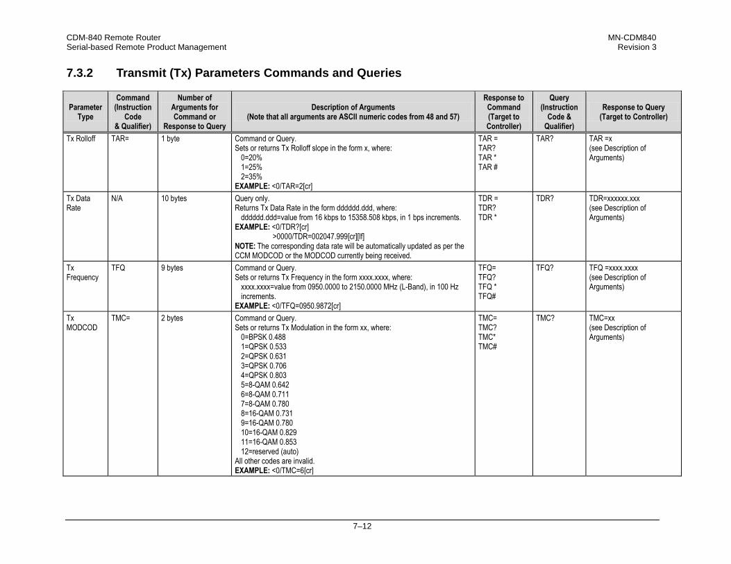
CDM-840 Remote Router MN-CDM840 Serial-based Remote Product Management Revision 3
7–12
7.3.2 Transmit (Tx) Parameters Commands and Queries
Parameter Type
Command (Instruction
Code & Qualifier)
Number of Arguments for Command or
Response to Query
Description of Arguments (Note that all arguments are ASCII numeric codes from 48 and 57)
Response to Command (Target to Controller)
Query (Instruction
Code & Qualifier)
Response to Query (Target to Controller)
Tx Rolloff TAR= 1 byte Command or Query. Sets or returns Tx Rolloff slope in the form x, where:
0=20% 1=25% 2=35%
EXAMPLE: <0/TAR=2[cr]
TAR = TAR? TAR * TAR #
TAR? TAR =x (see Description of Arguments)
Tx Data Rate
N/A 10 bytes
Query only. Returns Tx Data Rate in the form dddddd.ddd, where:
dddddd.ddd=value from 16 kbps to 15358.508 kbps, in 1 bps increments. EXAMPLE: <0/TDR?[cr] >0000/TDR=002047.999[cr][lf] NOTE: The corresponding data rate will be automatically updated as per the CCM MODCOD or the MODCOD currently being received.
TDR = TDR? TDR *
TDR? TDR=xxxxxx.xxx (see Description of Arguments)
Tx Frequency
TFQ 9 bytes Command or Query. Sets or returns Tx Frequency in the form xxxx.xxxx, where:
xxxx.xxxx=value from 0950.0000 to 2150.0000 MHz (L-Band), in 100 Hz increments.
EXAMPLE: <0/TFQ=0950.9872[cr]
TFQ= TFQ? TFQ * TFQ#
TFQ? TFQ =xxxx.xxxx (see Description of Arguments)
Tx MODCOD
TMC= 2 bytes Command or Query. Sets or returns Tx Modulation in the form xx, where:
0=BPSK 0.488 1=QPSK 0.533 2=QPSK 0.631 3=QPSK 0.706 4=QPSK 0.803 5=8-QAM 0.642 6=8-QAM 0.711 7=8-QAM 0.780 8=16-QAM 0.731 9=16-QAM 0.780 10=16-QAM 0.829 11=16-QAM 0.853 12=reserved (auto)
All other codes are invalid. EXAMPLE: <0/TMC=6[cr]
TMC= TMC? TMC* TMC#
TMC? TMC=xx (see Description of Arguments)
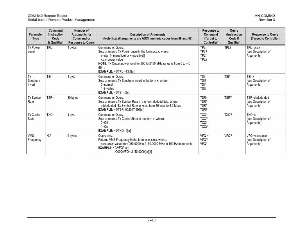
CDM-840 Remote Router MN-CDM840 Serial-based Remote Product Management Revision 3
7–13
Parameter Type
Command (Instruction
Code & Qualifier)
Number of Arguments for Command or
Response to Query
Description of Arguments (Note that all arguments are ASCII numeric codes from 48 and 57)
Response to Command (Target to Controller)
Query (Instruction
Code & Qualifier)
Response to Query (Target to Controller)
Tx Power Level
TPL= 4 bytes Command or Query. Sets or returns Tx Power Level in the form sxx.x, where:
s=sign [– (negative) or + (positive)] xx.x=power value
NOTE: Tx Output power level for 950 to 2150 MHz range is from 0 to -40 dBm. EXAMPLE: <0/TPL=-13.4[cr]
TPL= TPL? TPL* TPL#
TPL? TPL=sxx.x (see Description of Arguments)
Tx Spectrum Invert
TSI= 1 byte Command or Query. Sets or returns Tx Spectrum invert in the form x, where:
0=normal 1=inverted
EXAMPLE: <0/TSI =0[cr]
TSI= TSI? TSI* TSI#
TSI? TSI=x (see Description of Arguments)
Tx Symbol Rate
TSR= 10 bytes Command or Query. Sets or returns Tx Symbol Rate in the form dddddd.ddd, where:
dddddd.ddd=Tx Symbol Rate in ksps, from 16 ksps to 4.5 Msps EXAMPLE: <0/TSR=002047.999[cr]
TSR= TSR? TSR* TSR#
TSR? TSR=dddddd.ddd (see Description of Arguments)
Tx Carrier State
TXO= 1 byte Command or Query. Sets or returns Tx Carrier State in the form x, where:
0=Off 1=On
EXAMPLE: <0/TXO=1[cr]
TXO= TXO? TXO* TXO#
TXO? TXO=x (see Description of Arguments)
VMS Frequency
N/A 9 bytes Query only. Returns VMS Frequency in the form xxxx.xxxx, where:
xxxx.xxxx=value from 950.0000 to 2150.0000 MHz in 100 Hz increments. EXAMPLE: <0/VFQ?[cr] >0000/VFQ= 2150.0000[cr][lf]
VFQ = VFQ? VFQ*
VFQ? VFQ =xxxx.xxxx (see Description of Arguments)
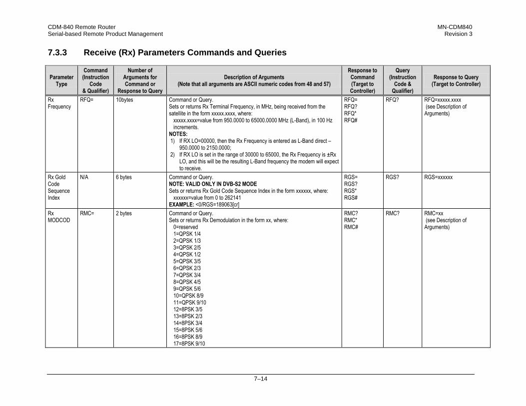
CDM-840 Remote Router MN-CDM840 Serial-based Remote Product Management Revision 3
7–14
7.3.3 Receive (Rx) Parameters Commands and Queries
Parameter Type
Command (Instruction
Code & Qualifier)
Number of Arguments for Command or
Response to Query
Description of Arguments (Note that all arguments are ASCII numeric codes from 48 and 57)
Response to Command (Target to Controller)
Query (Instruction
Code & Qualifier)
Response to Query (Target to Controller)
Rx Frequency
RFQ= 10bytes
Command or Query. Sets or returns Rx Terminal Frequency, in MHz, being received from the satellite in the form xxxxx.xxxx, where:
xxxxx.xxxx=value from 950.0000 to 65000.0000 MHz (L-Band), in 100 Hz increments.
NOTES: 1) If RX LO=00000, then the Rx Frequency is entered as L-Band direct –
950.0000 to 2150.0000; 2) If RX LO is set in the range of 30000 to 65000, the Rx Frequency is ±Rx
LO, and this will be the resulting L-Band frequency the modem will expect to receive.
RFQ= RFQ? RFQ* RFQ#
RFQ?
RFQ=xxxxx.xxxx (see Description of Arguments)
Rx Gold Code Sequence Index
N/A 6 bytes Command or Query. NOTE: VALID ONLY IN DVB-S2 MODE Sets or returns Rx Gold Code Sequence Index in the form xxxxxx, where:
xxxxxx=value from 0 to 262141 EXAMPLE: <0/RGS=189063[cr]
RGS= RGS? RGS* RGS#
RGS? RGS=xxxxxx
Rx MODCOD
RMC= 2 bytes Command or Query. Sets or returns Rx Demodulation in the form xx, where:
0=reserved 1=QPSK 1/4 2=QPSK 1/3 3=QPSK 2/5 4=QPSK 1/2 5=QPSK 3/5 6=QPSK 2/3 7=QPSK 3/4 8=QPSK 4/5 9=QPSK 5/6 10=QPSK 8/9 11=QPSK 9/10 12=8PSK 3/5 13=8PSK 2/3 14=8PSK 3/4 15=8PSK 5/6 16=8PSK 8/9 17=8PSK 9/10
RMC? RMC* RMC#
RMC?
RMC=xx (see Description of Arguments)

CDM-840 Remote Router MN-CDM840 Serial-based Remote Product Management Revision 3
7–15
Parameter Type
Command (Instruction
Code & Qualifier)
Number of Arguments for Command or
Response to Query
Description of Arguments (Note that all arguments are ASCII numeric codes from 48 and 57)
Response to Command (Target to Controller)
Query (Instruction
Code & Qualifier)
Response to Query (Target to Controller)
Rx MODCOD (cont.)
18=16-APSK 2/3 19=16-APSK 3/4 20=16-APSK 4/5 21=16-APSK 5/6 22=16-APSK 8/9 23=16-APSK 9/10 24=32-APSK 3/4 25=32-APSK 4/5 26=32-APSK 5/6 27=32-APSK 8/9 28=32-APSK 9/10 29=auto (ACM only)
All other codes are invalid. EXAMPLE: <0/RMC=6[cr]
Rx Spectrum Invert
N/A 1 byte Query only. Returns Rx Spectrum Invert in the form x, where:
0=Normal 1=Rx Spectrum Inverted
EXAMPLE: <0/RSI?[cr] >0000/RSI=1[cr][lf]
RSI? RSI* RSI#
RSI?
RSI=x (see Description of Arguments)
Rx Symbol Rate
RSR= 10 bytes Command or Query. Sets or returns Rx Symbol Rate in the form dddddd.ddd, where:
dddddd.ddd=value, in ksps, from 16ksps to 4.5Msps EXAMPLE: <0/RSR =002047.999[cr]
RSR= RSR? RSR * RSR #
RSR? RSR =dddddd.ddd (see Description of Arguments)

CDM-840 Remote Router MN-CDM840 Serial-based Remote Product Management Revision 3
7–16
7.3.4 Demodulator Status Commands and Queries
Parameter Type
Command (Instruction
Code & Qualifier)
Number of Arguments for Command or
Response to Query
Description of Arguments (Note that all arguments are ASCII numeric codes from 48 and 57)
Response to Command (Target to Controller)
Query (Instruction
Code & Qualifier)
Response to Query (Target to Controller)
Rx Es/No N/A 4 bytes Query only. Returns the value of Es/No in the form xx.x, where:
xx.x=value, in dB, from -1 to -40 (negative sign (-) is implied) in 0.1 dB increments.
NOTES: 1) The Es/No number correspond to the value that is displayed on HTTP
(via the Virtual Front Panel) or SNMP. This value is averaged in the background for the previous 16 values.
2) For a faster Es/No reading use REN command. EXAMPLE: <0/EBN?[cr]
RESPONSE NOTES: 1) Returns 99.9 if demod is unlocked. 2) Returns +040 for values greater than -40.0 dB.
N/A ESN? ESN=xxxxx (see Description of Arguments)
Rx Signal Level
N/A 5 bytes Query only. Returns the value of the Rx signal level, in dBm, in the form xxxxx, where:
xxxxx=value, in dBm, from -25 to -55 with a tolerance of ±5 dBm, in 0.5 dBm increments.
EXAMPLE: <0/RSL?[cr] RESPONSE NOTES: 1) If in the range of -25 to -55 dBm, returns RSL=-xx.y 2) If >-25 dBm, returns SL1=GT-25 (GT=‘greater than’) 3) If <-55 dBm, returns SL1=LT-55 (LT=‘less than’)
N/A RSL? RSL=xxxxx (see Description of Arguments)

CDM-840 Remote Router MN-CDM840 Serial-based Remote Product Management Revision 3
7–17
7.3.5 Transmit (Tx) BERT Command or Query
Parameter Type
Command (Instruction
Code & Qualifier)
Number of Arguments for Command or
Response to Query
Description of Arguments (Note that all arguments are ASCII numeric codes from 48 and 57)
Response to Command (Target to Controller)
Query (Instruction
Code & Qualifier)
Response to Query (Target to Controller)
Tx BERT State
BTX= 1 byte Command or Query. Sets or returns Tx BERT State in the form x, where:
0=Off 1=On
EXAMPLE: <0/BTX=1[cr]
BTX= BTX? BTX#
BTX? BTX=x (see Description of Arguments)
7.3.6 Receive (Rx) BERT Command or Query
Parameter Type
Command (Instruction
Code & Qualifier)
Number of Arguments for Command or
Response to Query
Description of Arguments (Note that all arguments are ASCII numeric codes from 48 and 57)
Response to Command (Target to Controller)
Query (Instruction
Code & Qualifier)
Response to Query (Target to Controller)
Rx BERT State
BRX= 1 byte Command or Query Sets or returns Rx BERT state in the form x, where:
0=Off 1=On
EXAMPLE: <0/BRX=1[cr]
BRX = BRX? BRX * BRX #
BRX? BRX=x (see Description of Arguments)
7.3.7 BUC (Block Up Converter) Parameters Commands and Queries
Parameter Type
Command (Instruction
Code & Qualifier)
Number of Arguments for Command or
Response to Query
Description of Arguments (Note that all arguments are ASCII numeric codes from 48 and 57)
Response to Command (Target to Controller)
Query (Instruction
Code & Qualifier)
Response to Query (Target to Controller)
BUC Attenuation
ATT= 4 bytes Command or Query. Sets or returns BUC attenuation level in the form xxxx, where:
xxxx=value from -1 to 3000 (in 1/100 dB), in 0.25 dB increments EXAMPLE: <0/ATT=2[cr]
ATT= ATT? ATT* ATT#
ATT? ATT=xxxx (see Description of Arguments)
BUC FSK Address
BAD= 2 bytes Command or Query. NOTE: FOR USE ONLY WITH BUCS THAT SUPPORT FSK. Sets or returns BUC Address in the form xx, where:
xx=value from 01 to 15 EXAMPLE: <0/BAD=1[cr]
BAD= BAD? BAD* BAD#
BAD? BAD=xx (see Description of Arguments)

CDM-840 Remote Router MN-CDM840 Serial-based Remote Product Management Revision 3
7–18
Parameter Type
Command (Instruction
Code & Qualifier)
Number of Arguments for Command or
Response to Query
Description of Arguments (Note that all arguments are ASCII numeric codes from 48 and 57)
Response to Command (Target to Controller)
Query (Instruction
Code & Qualifier)
Response to Query (Target to Controller)
BUC Current High Limit
BCH= 4 bytes Command or Query. Sets or returns the BUC Current High Limit in the form xxxx, where:
xxxx=value from 0 to 4000 mA, in 100 mA increments EXAMPLE: <0/BCH=2300[cr]
BCH= BCH? BCH* BCH#
BCH? BCH=xxxx (see Description of Arguments)
BUC Current Low Limit
BCL= 4 bytes Command or Query. Sets or returns the BUC Current Low Limit in the form xxxx, where:
xxxx=value from 0 to 4000 mA, in 100 mA increments. EXAMPLE: <0/BCL=1200[cr]
BCL= BCL? BCL* BCL#
BCL? BCL=xxxx (see Description of Arguments)
BUC DC Current
N/A 4 bytes Query only. Returns the value of the BUC DC current in the form xxxx, where:
xxxx=value from 0 to 9999 mA. EXAMPLE: <0/BDC?[cr] >0000/BDC=9999[cr][lf] NOTE: If not available, response is 0000.
N/A BDC? BDC=xxxx (see Description of Arguments)
BUC Voltage
N/A 4 bytes Query only. Returns the value of the BUC Voltage in the form xx.x, where:
xx.x=value from 0 to 64.0 Volts. EXAMPLE: <0/BDV?[cr] >0000/BDV=64.0[cr][lf]
N/A BDV? BDV=xx.x (see Description of Arguments)
BUC 10 MHz Reference
BFR= 1 byte Command or Query. Sets or returns the BUC 10 MHz Reference control in the form x, where:
0=Off 1=On
EXAMPLE: <0/BOE=1[cr]
BFR= BFR? BFR* BFR#
BFR? BFR=x (see Description of Arguments)
BUC RF Output
BOE= 1 byte Command or Query. Sets or returns the BUC output power enable in the form x, where:
0=Off 1=On
EXAMPLE: <0/BFR=1[cr]
BOE= BOE? BOE* BOE#
BOE? BOE=x (see Description of Arguments)
BUC Output Power
N/A 3 bytes Query only. Returns the BUC output power level in the form xxx, where:
xxx=value from 0 to 999 dBm, in 0.1 dBm increments. EXAMPLE: <0/BOL?[cr] >0000/BOL=45[cr][lf] (returns 4.5 dBm). RESPONSE NOTE: Returns 0 when FSK and BUC power are not enabled.
BOL= BOL? BOL* BOL#
BOL? BOL=xxx (see Description of Arguments)

CDM-840 Remote Router MN-CDM840 Serial-based Remote Product Management Revision 3
7–19
Parameter Type
Command (Instruction
Code & Qualifier)
Number of Arguments for Command or
Response to Query
Description of Arguments (Note that all arguments are ASCII numeric codes from 48 and 57)
Response to Command (Target to Controller)
Query (Instruction
Code & Qualifier)
Response to Query (Target to Controller)
BUC PLL Lock
N/A 1 byte Query only. NOTE: VALID ONLY WHEN THE FSK AND BUC POWER ARE ON. Returns the BUC Phase Lock Loop in the form x, where:
0=Locked 1=Unlocked 9=Not connected
EXAMPLE: <0/BPA?[cr] >0000/BPA=1[cr][lf]
N/A BPA? BPA=x (see Description of Arguments)
BUC Power Class
N/A 2 bytes Query only. NOTE: VALID ONLY WHEN THE FSK AND BUC POWER ARE ON. Returns the power level, in watts, for C-Band and Ku-Band in the form xx, where:
1=2 watts 2=4 watts 3=5 watts 4=8 watts 5=10 watts 6=16 watts 7=20 watts 8=25 watts 9=40 watts 10=60 watts
EXAMPLE: <0/BPC?[cr] >0000/BPC=10[cr][lf]
N/A BPC? BPC=xx (see Description of Arguments)
BUC Power Supply enable
BPS= 1 byte Command or Query. Sets or returns the BUC Power Supply control in the form x, where:
0=Disable 1=Enable
EXAMPLE: <0/BPS=1[cr]
BPS= BPS? BPS* BPS#
BPS? BPS=x (see Description of Arguments)
BUC Software Version
N/A 2 bytes Query only. NOTE: VALID ONLY WHEN THE FSK AND BUC POWER ARE ON. Returns the BUC Software Version in the form xx, where:
xx=0 or 15 EXAMPLE: <0/BSV?[cr] >0000/BSV=15[cr][lf]
N/A BSV? BSV=x (see Description of Arguments)

CDM-840 Remote Router MN-CDM840 Serial-based Remote Product Management Revision 3
7–20
Parameter Type
Command (Instruction
Code & Qualifier)
Number of Arguments for Command or
Response to Query
Description of Arguments (Note that all arguments are ASCII numeric codes from 48 and 57)
Response to Command (Target to Controller)
Query (Instruction
Code & Qualifier)
Response to Query (Target to Controller)
BUC Power Supply enable
N/A 4 byte Query only. NOTE: VALID ONLY WHEN THE FSK AND BUC POWER ARE ON. Returns the BUC temperature, in degrees Celsius, in the form x, where:
x=value from -127 to 127 EXAMPLE: <0/BUT?[cr] >0000/BUT=15[cr][lf]
BUT= BUT? BUT* BUT#
BUT? BUT=x (see Description of Arguments)

CDM-840 Remote Router MN-CDM840 Serial-based Remote Product Management Revision 3
7–21
7.3.8 LNB (Low-Noise Block Down Converter) Parameters Commands and Queries
Parameter Type
Command (Instruction
Code & Qualifier)
Number of Arguments for Command or
Response to Query
Description of Arguments (Note that all arguments are ASCII numeric codes from 48 and 57)
Response to Command (Target to Controller)
Query (Instruction
Code & Qualifier)
Response to Query (Target to Controller)
LNB Current
N/A 4 bytes Query only. Returns the LNB Current value, in mA, in the form xxxx.
N/A LNC?
LNC=xxxx (see Description of Arguments)
LNB Current High Limit
LNH= 3 bytes Command or Query. Sets or returns the LNB Current High Limit value in the form xxx, where:
xxx=value from 0 to 500 mA. EXAMPLE: <0/LNH=123[cr]
LNH= LNH? LNH* LNH#
LNH? LNH=xxx (see Description of Arguments)
LNB Current Low Limit
LNL= 3 bytes Command or Query. Sets or returns the LNB Current Low Limit value in the form xxx, where:
xxx= value from 0 to 500 mA. EXAMPLE: <0/LNL=123[cr]
LNL = LNL? LNL * LNL #
LNL? LNL =xxx (see Description of Arguments)
LNB Reference Enable
LNR= 1 byte Command or Query. Sets or returns the LNB Reference enable in the form x, where:
0=Disable 1=Enable
EXAMPLE: <0/LNR=1[cr]
LNR= LNR? LNR* LNR#
LNR? LNR=x (see Description of Arguments)
LNB DC Power Control
LPS= 1 byte Command or Query Sets or returns the LNB DC Power Supply Control in the form x, where:
0=Off 1=13V LNB Voltage 2=18V LNB Voltage 3=24V LNB Voltage
EXAMPLE: <0/LPS=3[cr]
LPS= LPS? LPS* LPS#
LPS? LPS=x (see Description of Arguments)
LNB Voltage
N/A 4 bytes Query only. Returns the LNB voltage value, in the form xxxx.
N/A LVO?
LVO=xxxx (see Description of Arguments)

CDM-840 Remote Router MN-CDM840 Serial-based Remote Product Management Revision 3
7–22
7.3.9 Unit Parameters Commands and Queries
Parameter Type
Command (Instruction
Code & Qualifier)
Number of Arguments for Command or
Response to Query
Description of Arguments (Note that all arguments are ASCII numeric codes from 48 and 57)
Response to Command (Target to Controller)
Query (Instruction
Code & Qualifier)
Response to Query (Target to Controller)
Equipment ID N/A 37 bytes Query only. Returns the equipment ID and installed options in the form AAAAssssBCDEFGHIJKsssssssssssssssssss, where: AAAA=The modem model number (default 0840) ssss (4 spares)=Installed hardware (default 0000) BCDEFGHIJKsssssssssssssssssss=Software FAST options, where: B=Tx Data/Symbol Rate option:
0=Standard: CCM 16 kbps to 256 kbps 1=CCM 16 kbps to 512bps 2=CCM 16 kbps to 1024 kbps 3=CCM 16 kbps to 2048 kbps 4=CCM 16 kbps to 5 Mbps 5=CCM 16 kbps to 10 Mbps 6=CCM 16 kbps to 15 Mbps 7=ACM 37 ksps to 100 ksps (future) 8=ACM 37 ksps to 200 ksps (future) 9=ACM 37 ksps to 400 ksps (future) A=ACM 37 ksps to 800 ksps (future) B=ACM 37 ksps to 1200 ksps (future) C=ACM 37 ksps to 2400 ksps (future) D=CCM 37 ksps to 4100 ksps (future)
C=Rx Data/Symbol Rate option: 0=Standard: CCM 1 Mbps to 15 Mbps 1=CCM 1 Mbps to 45 Mbps 2=CCM 1 Mbps to 100 Mbps 3=CCM 1 Mbps to 140 Mbps 4=CCM 1 Mbps to 167 Mbps 5=ACM 1 Msps to 5 Msps (future) 6=ACM 1 Msps to 15 Msps (future) 7=ACM 1 Msps to 34 Msps (future) 8=ACM 1 Msps to 47 Msps (future) 9=ACM 1 Msps to 62 Msps (future)
N/A EID? EID=AAAAssssBCDEFGHIJKsssssssssssssssssss (see Description of Arguments)

CDM-840 Remote Router MN-CDM840 Serial-based Remote Product Management Revision 3
7–23
Parameter Type
Command (Instruction
Code & Qualifier)
Number of Arguments for Command or
Response to Query
Description of Arguments (Note that all arguments are ASCII numeric codes from 48 and 57)
Response to Command (Target to Controller)
Query (Instruction
Code & Qualifier)
Response to Query (Target to Controller)
Equipment ID (cont.)
D=E1 Interface – WAN Adaptation: 0=None 1=1 TRX (up to 3 DSO can be selected) 2=2 TRX (up to 6 DSO can be selected) 3=3 TRX (up to 9 DSO can be selected) 4=6 TRX (up to 18 DSO can be selected) 5=9 TRX (up to 27 DSO can be selected) 6=9+ TRX / Full E1 (up to 32 DSO can be selected)
E=Header Compression Tx Data Rate (CCM)/ Symbol Rate (ACM): 0=None 1=up to 256 kbps (CCM) / 100 ksps (ACM) 2=up to 512 kbps (CCM) / 200 ksps (ACM) 3=up to 1024 kbps (CCM) / 400 ksps (ACM) 4=up to 2048 kbps (CCM) / 800 ksps (ACM) 5=up to 5 Mbps (CCM) / 1200 ksps (ACM) 6=up to 10 Mbps (CCM) / 2400 ksps (ACM) 7=up to 15 Mbps (CCM) / 4100 ksps (ACM)
F=Header Decompression Rx Data Rate (CCM)/ Symbol Rate (ACM): 0=None 1=up to 15 Mbps (CCM) / 5 Msps (ACM) 2=up to 45 Mbps (CCM) / 15 Msps (ACM) 3=up to 100 Mbps (CCM) / 34 Msps (ACM) 4=up to 140 Mbps (CCM) / 47 Msps (ACM) 5=up to 167 Mbps (CCM) / 62 Msps (ACM)
G=Payload Compression Tx Data Rate (CCM)/ Symbol Rate (ACM): 0=None 1=up to 256 kbps (CCM) / 100 ksps (ACM) 2=up to 512 kbps (CCM) / 200 ksps (ACM) 3=up to 1024 kbps (CCM) / 400 ksps (ACM) 4=up to 2048 kbps (CCM) / 800 ksps (ACM) 5=up to 5 Mbps (CCM) / 1200 ksps (ACM) 6=up to 10 Mbps (CCM) / 2400 ksps (ACM) 7=up to 15 Mbps (CCM) / 4100 ksps (ACM)
H=Payload Decompression Rx Data Rate (CCM)/ Symbol Rate (ACM): 0=None 1=up to 15 Mbps (CCM) / 5 Msps (ACM) 2=up to 45 Mbps (CCM) / 15 Msps (ACM) 3=up to 100 Mbps (CCM) / 34 Msps (ACM) 4=up to 140 Mbps (CCM) / 47 Msps (ACM) 5=up to 167 Mbps (CCM) / 62 Msps (ACM)

CDM-840 Remote Router MN-CDM840 Serial-based Remote Product Management Revision 3
7–24
Parameter Type
Command (Instruction
Code & Qualifier)
Number of Arguments for Command or
Response to Query
Description of Arguments (Note that all arguments are ASCII numeric codes from 48 and 57)
Response to Command (Target to Controller)
Query (Instruction
Code & Qualifier)
Response to Query (Target to Controller)
Equipment ID (cont.)
I=Quality of Service 0=None 1=Basic QoS (Diffserv + SAR) 2=Advanced QoS (Basic QoS + Rule Based QoS)
J=G.702 Clock Extension 0=None 1=Enabled
K=Dynamic SCPC 0=None 1=Enabled
sssssssssssssssssss (19 spares)
Faults and Status
N/A 16 bytes Query only. Returns the current highest-priority fault and status codes for the Unit (hardware), TX Traffic, RX Traffic, and ODUs in the form abcdefxxxxxxxxxx, where: a=Unit status:
0=No faults 1=+5 V Power Supply fault 2=+12 V Power Supply fault 3=Tx synthesizer unlocked 4=Tx/Rx FPGA PLL unlocked 5=Tx/Rx FPGA load fail 6=Compression FPGA load fail
b=Tx Traffic status: 0=Tx traffic OK
c=Rx Traffic status: 0=Rx Traffic OK 1=Demodulator unlocked 2=Es/No Alarm
d=BUC status/faults: 0=BUC OK 1=BUC Current 2=BUC Voltage
e=LNB status/faults: 0=OK, masked or not present 1=LNB current 2=LNB voltage
f=Traffic/GE Interface Fault (reports as Unit Fault) 0=OK 1=No Link
xxxxxxxxxx (10 spares)
N/A FLT? FLT=abcdefxxxxxxxxxx (see Description of Arguments)

CDM-840 Remote Router MN-CDM840 Serial-based Remote Product Management Revision 3
7–25
Parameter Type
Command (Instruction
Code & Qualifier)
Number of Arguments for Command or
Response to Query
Description of Arguments (Note that all arguments are ASCII numeric codes from 48 and 57)
Response to Command (Target to Controller)
Query (Instruction
Code & Qualifier)
Response to Query (Target to Controller)
Adjustment for Internal 10MHz High- stability Reference
ADJ= 4 bytes Command or Query. Sets or returns the fine adjustment of the Internal 10MHz Reference on the High-Stability Frequency Reference module in the form sddd, where:
s=sign [– (negative) or + (positive)] ddd=value from 0 to 999.
EXAMPLE: <0/ADJ=-123[cr]
ADJ= ADJ? ADJ* ADJ#
ADJ? ADJ=sddd (see Description of Arguments)
Circuit ID String
CID= 4 to 32 bytes Command or Query. Sets or returns the user-defined Circuit ID string, which is 4 to 32 characters in length. NOTE: Valid characters include Space ( ) * + – , . / 0 thru 9 and A thru Z EXAMPLE: <0/CID=RxCircuitID[cr]
CID= CID? CID* CID#
CID? CID=x [4..32] (see Description of Arguments)
Default Password
DPW= N/A Command only. NOTE: THIS COMMAND TAKES NO ARGUMENTS. Resets the admin username/password to: Username=“comtech” Password=“comtech”
DPW= DPW? DPW* DPW#
N/A N/A
Firmware information
N/A 100 bytes Query only. Returns firmware information for Image 0, 1 or 2, where:
0=Bootrom Information 1=Image #1 Firmware Information 2=Image #2 Firmware Information
The information return in the form xxxxx…,mm/dd/yy where: xxxxx…=The firmware number mm/dd/yy=The firmware date in month/date/year EXAMPLE: <0/FRW?1[cr]
N/A FRW?0 FRW?1 FRW?2
FRW=xxxxx…,mm/dd/yy (see Description of Arguments)
Geographical Log Information
GLG=
18 bytes Command only. Sets the geographical log information in the form AAAAOOOOOXNNNNNNNN, where:
AAAA=Latitude OOOOO=Longitude X=exclusion zone status (0 or 1) NNNNNNNN=name of satellite used
NOTE: Data is stored in the file “GPS.log.” Data in the log file older than one year is removed from the log file. The format of the text in the log file is a single GLG command per line: WWWWSSSSSSSSFFFFFFFFBBBBBBBBMAAAAOOOOONNNNNNNN, where:
GLG= GLG?
N/A
GLG=AAAAOOOOOXN NNNNNNN (see Description of Arguments)

CDM-840 Remote Router MN-CDM840 Serial-based Remote Product Management Revision 3
7–26
Parameter Type
Command (Instruction
Code & Qualifier)
Number of Arguments for Command or
Response to Query
Description of Arguments (Note that all arguments are ASCII numeric codes from 48 and 57)
Response to Command (Target to Controller)
Query (Instruction
Code & Qualifier)
Response to Query (Target to Controller)
Geographical Log Information (cont.)
WWWW=hex representation of the weeks field (weeks since 1/6/1980) SSSSSSSS=hex representation of the seconds field (seconds this week) FFFFFFFF=hex representation of the Tx frequency BBBBBBBB=hex representation of the Tx symbol rate M=bitmap for exclusion setting from user, and if locked from the router bit, where:
0=lock bit 1=exclusion bit
AAAA=Latitude from user input OOOOO=Longitude from user input NNNNNNNN=Satellite naming string (from 1 to 8 characters)
Traffic IP IG1= 18 bytes Command or Query. Sets or returns the IP Address and network prefix for the 10/100 BaseT Ethernet Traffic port, in the form xxx.xxx.xxx.xxx/yy, where:
xxx.xxx.xxx.xxx=the IP Address yy=the network prefix (8-30)
EXAMPLE: <0/IG1=192.168.001.004/24[cr]
IG1= IG1? IG1* IG1#
IG1? IG1=xx.xxx.xxx.xxx/yy (see Description of Arguments)
Current Software Image
N/A 1 byte Query Only. Returns active software image in the form x, where:
1=Bulk Image #1 currently active 2=Bulk Image #2 currently active
EXAMPLE: <0/IMG?[cr] >0000/IMG=2[cr][lf]
N/A IMG? IMG=x (see Description of Arguments)
Management IP Address
IPA= 18 bytes Command or Query. Sets or returns the IP Address and network prefix for the 10/100 BaseT Fast Ethernet FE Management port, in the form xxx.xxx.xxx.xxx/yy, where:
xxx.xxx.xxx.xxx=the IP Address yy=the network prefix (8-30)
EXAMPLE: <0/IPG=192.168.001.004/24[cr]
IPA= IPA? IPA* IPA#
IPA? IPA=xx.xxx.xxx.xxx/yy (see Description of Arguments)
GE Link Configuration
LC1= 1 byte Command or Query. Sets or returns the 10/100/1000 BaseT Gigibit Ethernet GE traffic port Interface Mode in the form x, where:
0=Auto Negotiate 1=1000 Mbps Full Duplex 2=100 Mbps Full Duplex 3=100 Mbps Half Duplex 4=10 Mbps Full Duplex 5=10 Mbps Half Duplex
EXAMPLE: <0/LC1=3[cr]
LC1= LC1? LC1* LC1#
LC1? LC1=x (see Description of Arguments)

CDM-840 Remote Router MN-CDM840 Serial-based Remote Product Management Revision 3
7–27
Parameter Type
Command (Instruction
Code & Qualifier)
Number of Arguments for Command or
Response to Query
Description of Arguments (Note that all arguments are ASCII numeric codes from 48 and 57)
Response to Command (Target to Controller)
Query (Instruction
Code & Qualifier)
Response to Query (Target to Controller)
Management MAC Address
N/A 12 bytes, alphanumeric
Query only. Returns the unique FE management port MAC Address in the form xx:xx:xx:xx:xx:xx EXAMPLE: <0/MAC?[cr] >0000/MAC=00:06:B0:00:01:C2[cr][lf]
N/A MAC? MAC=xx:xx:xx:xx:xx:xx (see Description of Arguments)
GE MAC Address
N/A 12 bytes, alphanumeric
Query only. Returns the unique GE traffic port MAC Address in the form xx:xx:xx:xx:xx:xx EXAMPLE: <0/MG1?[cr]
>0000/MG1=00:06:B0:00:01:C2[cr][lf]
N/A MG1? MG1= xx:xx:xx:xx:xx:xx (see Description of Arguments)
Management Link Configuration
MLC= 1 byte Command or Query. Sets or returns 10/100 BaseT Fast Ethernet FE Management port Interface Mode in the form x, where:
0=Auto Negotiate 1=reserved 2=100 Mbps Full Duplex 3=100 Mbps Half Duplex 4=10 Mbps Full Duplex 5=10 Mbps – Half Duplex
EXAMPLE: <0/MLC=3[cr]
MLC = MLC? MLC * MLC #
MLC? MLC =x (see Description of Arguments)
Actual Negotiated Port Speed
N/A None Query only. Returns actual negotiated port speed in the form ab, where: a=GE traffic port negotiated port speed. b=FE management port negotiated port speed.
‘a’ and ‘b’ have the following values: 0=Link down 1=100 Full Duplex 2=100 Half Duplex 3=10 Full Duplex 4=10 Half Duplex 5=1000 Full Duplex
EXAMPLE: <0/NPS?[cr] >0000/NPS=2[cr][lf]
N/A NPS? NPS=ab (see Description of Arguments)
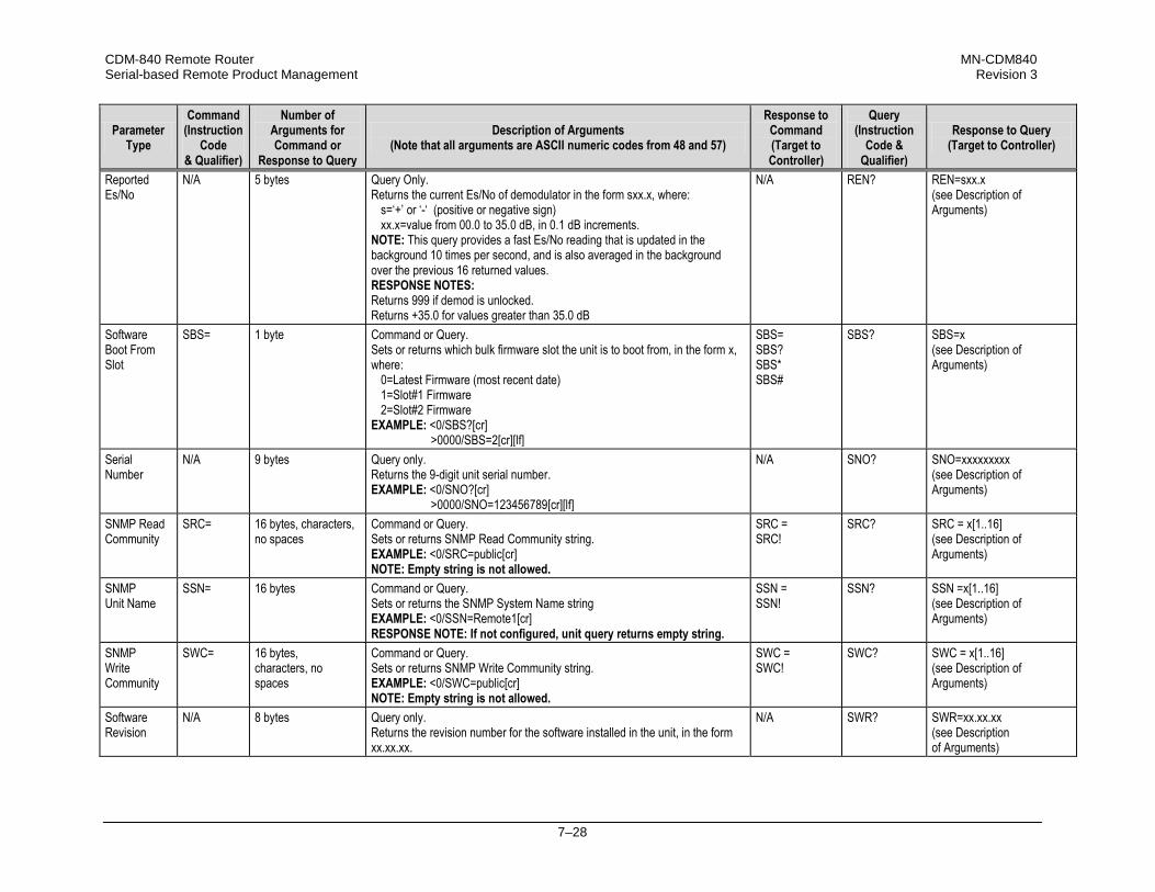
CDM-840 Remote Router MN-CDM840 Serial-based Remote Product Management Revision 3
7–28
Parameter Type
Command (Instruction
Code & Qualifier)
Number of Arguments for Command or
Response to Query
Description of Arguments (Note that all arguments are ASCII numeric codes from 48 and 57)
Response to Command (Target to Controller)
Query (Instruction
Code & Qualifier)
Response to Query (Target to Controller)
Reported Es/No
N/A
5 bytes Query Only. Returns the current Es/No of demodulator in the form sxx.x, where:
s=‘+’ or ‘-‘ (positive or negative sign) xx.x=value from 00.0 to 35.0 dB, in 0.1 dB increments.
NOTE: This query provides a fast Es/No reading that is updated in the background 10 times per second, and is also averaged in the background over the previous 16 returned values. RESPONSE NOTES: Returns 999 if demod is unlocked. Returns +35.0 for values greater than 35.0 dB
N/A REN?
REN=sxx.x (see Description of Arguments)
Software Boot From Slot
SBS= 1 byte Command or Query. Sets or returns which bulk firmware slot the unit is to boot from, in the form x, where:
0=Latest Firmware (most recent date) 1=Slot#1 Firmware 2=Slot#2 Firmware
EXAMPLE: <0/SBS?[cr] >0000/SBS=2[cr][lf]
SBS= SBS? SBS* SBS#
SBS? SBS=x (see Description of Arguments)
Serial Number
N/A 9 bytes
Query only. Returns the 9-digit unit serial number. EXAMPLE: <0/SNO?[cr] >0000/SNO=123456789[cr][lf]
N/A SNO? SNO=xxxxxxxxx (see Description of Arguments)
SNMP Read Community
SRC= 16 bytes, characters, no spaces
Command or Query. Sets or returns SNMP Read Community string. EXAMPLE: <0/SRC=public[cr] NOTE: Empty string is not allowed.
SRC = SRC!
SRC?
SRC = x[1..16] (see Description of Arguments)
SNMP Unit Name
SSN= 16 bytes Command or Query. Sets or returns the SNMP System Name string EXAMPLE: <0/SSN=Remote1[cr] RESPONSE NOTE: If not configured, unit query returns empty string.
SSN = SSN!
SSN? SSN =x[1..16] (see Description of Arguments)
SNMP Write Community
SWC=
16 bytes, characters, no spaces
Command or Query. Sets or returns SNMP Write Community string. EXAMPLE: <0/SWC=public[cr] NOTE: Empty string is not allowed.
SWC = SWC!
SWC? SWC = x[1..16] (see Description of Arguments)
Software Revision
N/A 8 bytes Query only. Returns the revision number for the software installed in the unit, in the form xx.xx.xx.
N/A SWR? SWR=xx.xx.xx (see Description of Arguments)

CDM-840 Remote Router MN-CDM840 Serial-based Remote Product Management Revision 3
7–29
Parameter Type
Command (Instruction
Code & Qualifier)
Number of Arguments for Command or
Response to Query
Description of Arguments (Note that all arguments are ASCII numeric codes from 48 and 57)
Response to Command (Target to Controller)
Query (Instruction
Code & Qualifier)
Response to Query (Target to Controller)
Unit Test Mode
TST= 1 byte Command or Query. Sets or returns Unit Test Mode in the form x, where:
0=Normal Mode (no test) 1=Tx CW 2=Tx Alternating 1,0 Pattern 3=QPSK PN Pattern
EXAMPLE: <0/TST=1[cr]
TST= TST? TST* TST#
TST? TST=x (see Description of Arguments)
7.3.10 Bulk Configuration String Commands
Parameter Type
Command (Instruction
Code & Qualifier)
Number of Arguments for Command or
Response to Query
Description of Arguments (Note that all arguments are ASCII numeric codes from 48 and 57)
Response to Command (Target to Controller)
Query (Instruction
Code & Qualifier)
Response to Query (Target to Controller)
Configuration Load
CLD= 1 byte Command only. Retrieves a previously stored modem configuration from the Configuration Memory location specified in the form x, where:
x=0 to 9. EXAMPLE: <0/CLD=4[cr]
CLD= CLD? CLD* CLD#
N/A N/A
Configuration Save
CST= 1 byte Command only. Stores the current modem configuration into the Configuration Memory location specified in the form x, where:
x=0 to 9. EXAMPLE: <0/CST=0[cr]
CST= CST? CST* CST#
N/A N/A

CDM-840 Remote Router MN-CDM840 Serial-based Remote Product Management Revision 3
7–30
7.3.11 Redundancy Commands and Queries
Parameter Type
Command (Instruction
Code & Qualifier)
Number of Arguments for Command or
Response to Query
Description of Arguments (Note that all arguments are ASCII numeric codes from 48 and 57)
Response to Command (Target to Controller)
Query (Instruction
Code & Qualifier)
Response to Query (Target to Controller)
Redundancy State
N/A 1 byte Query only. Returns the redundancy state of the unit in the form x, where:
0=Offline 1=Online
EXAMPLE: <0/RED?[cr] >0000/RED=1[cr][lf]
N/A RED? RED=x (see Description of Arguments)
Force 1:1 Switch
FSW= None Command only. This command takes no arguments. Forces the unit to toggle the Unit Fail relay to the “fail” state for approximately 500 ms. NOTES: 1) If the unit is a 1:1 pair and it is currently the ‘Online’ unit, this forces a
switchover so the unit will then be in ‘Standby’ mode 2) The command is always executed by the unit regardless of whether it is
stand-alone, in a 1:1 pair, or part of a 1:N system. EXAMPLE: <0/FSW=[cr]
FSW= FSW*
N/A N/A
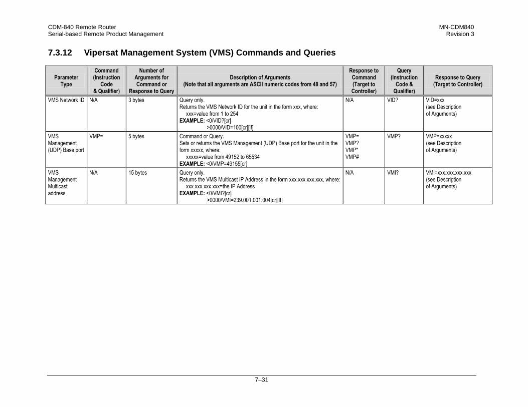
CDM-840 Remote Router MN-CDM840 Serial-based Remote Product Management Revision 3
7–31
7.3.12 Vipersat Management System (VMS) Commands and Queries
Parameter Type
Command (Instruction
Code & Qualifier)
Number of Arguments for Command or
Response to Query
Description of Arguments (Note that all arguments are ASCII numeric codes from 48 and 57)
Response to Command (Target to Controller)
Query (Instruction
Code & Qualifier)
Response to Query (Target to Controller)
VMS Network ID
N/A 3 bytes Query only. Returns the VMS Network ID for the unit in the form xxx, where:
xxx=value from 1 to 254 EXAMPLE: <0/VID?[cr] >0000/VID=100[cr][lf]
N/A VID? VID=xxx (see Description of Arguments)
VMS Management (UDP) Base port
VMP= 5 bytes Command or Query. Sets or returns the VMS Management (UDP) Base port for the unit in the form xxxxx, where:
xxxxx=value from 49152 to 65534 EXAMPLE: <0/VMP=49155[cr]
VMP= VMP? VMP* VMP#
VMP? VMP=xxxxx (see Description of Arguments)
VMS Management Multicast address
N/A 15 bytes Query only. Returns the VMS Multicast IP Address in the form xxx.xxx.xxx.xxx, where:
xxx.xxx.xxx.xxx=the IP Address EXAMPLE: <0/VMI?[cr] >0000/VMI=239.001.001.004[cr][lf]
N/A VMI? VMI=xxx.xxx.xxx.xxx (see Description of Arguments)

CDM-840 Remote Router MN-CDM840 Serial-based Remote Product Management Revision 3
7–32
7.3.13 Entry Channel Mode (ECM) Commands and Queries
Parameter Type
Command (Instruction
Code & Qualifier)
Number of Arguments for Command or
Response to Query
Description of Arguments (Note that all arguments are ASCII numeric codes from 48 and 57)
Response to Command (Target to Controller)
Query (Instruction
Code & Qualifier)
Response to Query (Target to Controller)
ECM Mode
EMD= 1 byte Command or Query. Sets or returns ECM Mode in the form x, where:
0=Disable 1=Offline 2=Wait 3=Online
EXAMPLE: <0/EMD=0[cr]
EMD= EMD? EMD* EMD#
EMD? EMD=x (see Description of Arguments)
TX Base Power
EBP= 4 bytes Command or Query. Sets or returns the Tx Base power in the form sxxx, where:
s=sign [– (negative) or + (positive)] xxx=power value from -400 to 0 in 0.1dB increments
EXAMPLE: <0/EBP=-252[cr] (sets Tx Base power @ -25.2dB)
EBP= EBP? EBP* EBP#
EBP? EBP=sxxx (see Description of Arguments)
ECM Multicast Address
EMI= 15 bytes Command or Query. Sets or returns the IP Address for the VMS Multicast IP in the form xxx.xxx.xxx.xxx, where:
xxx.xxx.xxx.xxx=the IP Address EXAMPLE: <0/EMI=192.168.001.004[cr]
EMI= EMI? EMI* EMI#
EMI? EMI=xxx.xxx.xxx.xxx (see Description of Arguments)
ECM Group ID
EGI= 3 bytes Command or Query. Sets or returns the ECM Group ID in the form xxx, where:
xxx=value from 0 to 255 EXAMPLE: <0/EGI=100[cr]
EGI= EGI? EGI* EGI#
EGI? EGI=xxx (see Description of Arguments)
ECM Mode Power Hunt Function
EPH= 1 byte Command or Query. Sets or returns the Power Hunt function when in ECM Mode in the form x, where:
0=Disabled 1=Enabled
EXAMPLE: <0/EPH=1[cr]
EPH= EPH? EPH* EPH#
EPH? EPH=x (see Description of Arguments)
RX LO Frequency
ERF= 5 bytes Command or Query. Sets or returns the RX LO frequency value in the form xxxxx, where:
xxxxx=value in MHz. EXAMPLE: <0/ERF=02300[cr]
ERF= ERF? ERF* ERF#
ERF? ERF=xxxxx (see Description of Arguments)
TX LO Frequency
ETF= 5 bytes Command or Query. Sets or returns the TX LO frequency value in the form xxxxx, where:
xxxxx=value in MHz EXAMPLE: <0/ETF=02300[cr]
ETF= ETF? ETF* ETF#
ETF? EBP=xxxxx (see Description of Arguments)
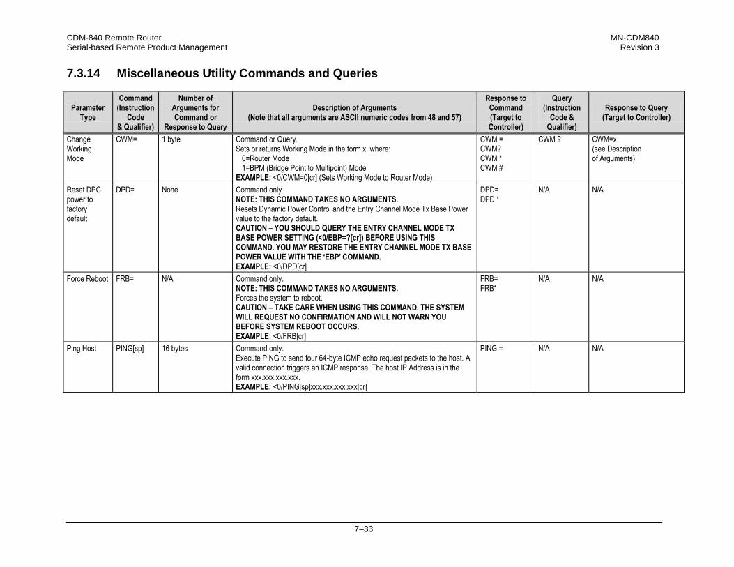
CDM-840 Remote Router MN-CDM840 Serial-based Remote Product Management Revision 3
7–33
7.3.14 Miscellaneous Utility Commands and Queries
Parameter Type
Command (Instruction
Code & Qualifier)
Number of Arguments for Command or
Response to Query
Description of Arguments (Note that all arguments are ASCII numeric codes from 48 and 57)
Response to Command (Target to Controller)
Query (Instruction
Code & Qualifier)
Response to Query (Target to Controller)
Change Working Mode
CWM= 1 byte Command or Query. Sets or returns Working Mode in the form x, where:
0=Router Mode 1=BPM (Bridge Point to Multipoint) Mode
EXAMPLE: <0/CWM=0[cr] (Sets Working Mode to Router Mode)
CWM = CWM? CWM * CWM #
CWM ? CWM=x (see Description of Arguments)
Reset DPC power to factory default
DPD= None Command only. NOTE: THIS COMMAND TAKES NO ARGUMENTS. Resets Dynamic Power Control and the Entry Channel Mode Tx Base Power value to the factory default. CAUTION – YOU SHOULD QUERY THE ENTRY CHANNEL MODE TX BASE POWER SETTING (<0/EBP=?[cr]) BEFORE USING THIS COMMAND. YOU MAY RESTORE THE ENTRY CHANNEL MODE TX BASE POWER VALUE WITH THE ‘EBP’ COMMAND. EXAMPLE: <0/DPD[cr]
DPD= DPD *
N/A N/A
Force Reboot FRB= N/A Command only. NOTE: THIS COMMAND TAKES NO ARGUMENTS. Forces the system to reboot. CAUTION – TAKE CARE WHEN USING THIS COMMAND. THE SYSTEM WILL REQUEST NO CONFIRMATION AND WILL NOT WARN YOU BEFORE SYSTEM REBOOT OCCURS. EXAMPLE: <0/FRB[cr]
FRB= FRB*
N/A N/A
Ping Host PING[sp] 16 bytes Command only. Execute PING to send four 64-byte ICMP echo request packets to the host. A valid connection triggers an ICMP response. The host IP Address is in the form xxx.xxx.xxx.xxx. EXAMPLE: <0/PING[sp]xxx.xxx.xxx.xxx[cr]
PING = N/A N/A

CDM-840 Remote Router MN-CDM840 Serial-based Remote Product Management Revision 3
7–34
Notes:

A–1
Appendix A. REFERENCE DOCUMENTATION
A.1 Overview
1) UNLESS OTHERWISE NOTED – This appendix collectively refers to the Comtech EF Data Advanced VSAT Series ODM-840 Remote Router, ODMR-840 Reduced Form Factor Remote Router, and ODMR-840B Remote Router Board Set as the ODM-840.
2) This appendix describes features that may be monitored or controlled by the user, or otherwise processed by the CDM-840 Remote Router. For detailed reading about the operational features of the Advanced VSAT Series group of products, consult the adjunct documentation that is specified in this appendix and is available for download from Comtech EF Data’s web site (www.comtechefdata.com).
Figure A-1. Advanced VSAT Series Hub and Remote Site Products

CDM-840 Remote Router MN-CDM840 Appendix A Revision 3
A–2
A.2 FEC (Forward Error Correction) Options
The method of FEC used among Comtech EF Data’s Advanced VSAT series of products differs according to Advanced VSAT Series product. This includes VersaFEC®, a family of short‐block Low Density Parity Check (LDPC) codes with very low latency. VersaFEC® is a patent pending technology wholly owned and developed by Comtech EF Data and Comtech AHA Enterprise Products Group (the VersaFEC name is a trademark registered to Comtech AHA). For the CDM-840 and ODM-840 Remote Routers: The FEC method used by the remote site CDM‐840 and ODM‐840 Remote Routers depends on the direction of signal processing in use:
• The Rx (receive) side of the 840 operates with error correction based upon the DVB‐S2
standard for QPSK, 8‐PSK, 16‐APSK and 32‐APSK with concatenated LDPC and Bose‐Chaudhuri‐Hocquenghem (BCH).
• The Tx (transmit) side of the 840 uses the VersaFEC® family of short‐block LDPC codes.
• Appendix B. FEC (FORWARD ERROR CORRECTION) OPTIONS in this manual.
• Appendix B. FEC (FORWARD ERROR CORRECTION) OPTIONS in the Comtech EF Data ODM-840 Remote Router / ODMR-840 Reduced Form Factor Remote Router / ODMR-840B Remote Router Board Set Installation and Operation Manual (CEFD P/N MN-ODM840)
For the CDD-880 Multi Receiver Router: The hub site CDD‐880 Multi Receiver Router uses the VersaFEC® family of short‐block LDPC codes.
Appendix B. FEC (FORWARD ERROR CORRECTION) OPTIONS in the Comtech EF Data CDD-880 Multi Receiver Router Installation and Operation Manual (CEFD P/N MN-CDD880)
For the CDM-800 Gateway Router via the CTOG-250 Comtech Traffic Optimization Gateway: The hub site CDM‐800 uses the FEC method based upon the DVB‐S2 standard for QPSK, 8‐PSK, 16‐APSK and 32‐APSK with concatenated LDPC and BCH.
Appendix B. FEC (FORWARD ERROR CORRECTION) OPTIONS in the CTOG-250 Comtech Traffic Optimization Gateway with CDM-800 Gateway Router Installation and Operation Manual (CEFD P/N MN-CTOG250)

CDM-840 Remote Router MN-CDM840 Appendix A Revision 3
A–3
A.3 ACM/VCM (Adaptive Coding and Modulation / Variable Coding and Modulation) Operation
The VersaFEC® Adaptive Coding and Modulation (ACM) feature is a patents‐pending technology owned and developed by Comtech EF Data and Comtech AHA Enterprise Products Group. ACM allows modulation and code rate (ModCod) to change on a frame‐by‐frame basis subject to current link conditions. As ACM converts available link margin into increased capacity, average capacity gain of 100% or more is possible. This maximizes each remote’s throughput under all conditions which, in turn, maximizes network efficiency and availability. ACM maximizes throughput regardless of link conditions (noise or other impairments, clear sky, rain fade, etc). Return Link ACM operation is available in the CDM‐840 and ODM‐840 Remote Routers and in the CDD‐880 Multi Receiver Routers. Outbound ACM operation is available in the CDM‐800 Gateway Router via the CTOG‐250 Comtech Traffic Optimization Gateway.
• Appendix D. VERSAFEC RETURN LINK ACM (ADAPTIVE CODING AND MODULATION) in this manual.
• Appendix D. VERSAFEC RETURN LINK ACM (ADAPTIVE CODING AND MODULATION) in the Comtech EF Data ODM-840 Remote Router / ODMR-840 Reduced Form Factor Remote Router / ODMR-840B Remote Router Board Set Installation and Operation Manual (CEFD P/N MN-ODM840)
• Appendix H. VERSAFEC RETURN LINK ACM (ADAPTIVE CODING AND MODULATION)
in the Comtech EF Data CDD-880 Multi Receiver Router Installation and Operation Manual (CEFD P/N MN-CDD880)
• Appendix E. OUTBOUND ACM (ADAPTIVE CODING AND MODULATION) in the CTOG-250 Comtech Traffic Optimization Gateway with CDM-800 Gateway Router Installation and Operation Manual (CEFD P/N MN-CTOG250)

CDM-840 Remote Router MN-CDM840 Appendix A Revision 3
A–4
A.4 BPM (Bridge Point-to-Multipoint) Operation
The Advanced VSAT BPM feature functions as a Learning Ethernet Switch when the “Working Mode” is set to BPM. This makes the Advanced VSAT equipment appear as a “Sky Ethernet Switch” and allows for a greatly simplified network deployment. In BPM Mode, all L2/L3/L4 protocols such as VLAN, MPLS, IPv6, OSPF, and BGP will flow through the network as they would through an off‐the‐shelf Ethernet Switch. The Advanced VSAT System, running in BPM Mode, supports Flat Networks, Flat Networks with Routers, and VLAN Trunking network topologies.
BPM operation is not available with the ODM-840 Remote Router.
• Appendix E. BPM (BRIDGE POINT-TO-MULTIPOINT) OPERATION in this manual.
• Appendix C. BPM (BRIDGE POINT-TO-MULTIPOINT) OPERATION in the Comtech EF Data CDD-880 Multi Receiver Router Installation and Operation Manual (CEFD P/N MN-CDD880)
• Appendix C. BPM (BRIDGE POINT-TO-MULTIPOINT) OPERATION in the CTOG-250
Comtech Traffic Optimization Gateway with CDM-800 Gateway Router Installation and Operation Manual (CEFD P/N MN-CTOG250)

CDM-840 Remote Router MN-CDM840 Appendix A Revision 3
A–5
A.5 ECM (Entry Channel Mode) Operation
ECM (Entry Channel Mode) operation is available in the CDM‐840 and ODM‐840 Remote Routers, and in the CDD‐880 Multi Receiver Router. ECM is a feature based on slotted Aloha with random retransmission backoff. It supports multiple carriers through frequency assignments, which provide simplified deployment and scalability. While a Remote Router is in Entry Channel Mode, it allows the passing of management traffic only – it will not transmit user data traffic. An ECM‐enabled Remote Router may remain in the entry channel for an extended period if “online” communications are not required, or if dSCPC (dynamic Single Carrier Per Channel) resources are unavailable. While idle or waiting in the entry channel, the Remote Router sends periodic health status messages to the CTOG‐250 and Vipersat Management System (VMS) while it continues to service VMS recovery logic timers.
• Appendix G. ECM (ENTRY CHANNEL MODE) in this manual.
• Appendix F. ECM (ENTRY CHANNEL MODE) in the Comtech EF Data ODM-840 Remote Router / ODMR-840 Reduced Form Factor Remote Router / ODMR-840B Remote Router Board Set Installation and Operation Manual (CEFD P/N MN-ODM840)
• Appendix D. ECM (ENTRY CHANNEL MODE) in the Comtech EF Data CDD-880 Multi Receiver Router Installation and Operation Manual (CEFD P/N MN-CDD880)

CDM-840 Remote Router MN-CDM840 Appendix A Revision 3
A–6
A.6 dMesh (VMS Dynamic Mesh) Connectivity
dMesh (Dynamic Mesh) operation is available in the CDM‐840 and ODM‐840 Remote Routers, and in the CDD‐880 Multi Receiver Router. Mesh connectivity minimizes the requirement for communications that are routed through a hub and re‐routed back to the remote segments of an Advanced VSAT Network. Comtech EF Data leverages the concept of Bandwidth‐on‐Demand (BoD) by taking advantage of dSCPC (Dynamic Single Channel per Carrier) in a mesh environment and adapting it to Comtech EF Data’s Advanced VSAT Network platform. This adds dynamic point‐to‐multipoint SCPC mesh circuits to the network’s existing hub and remote link, and DVB‐S2 outbound and VersaFEC dSCPC to the return link. Comtech EF Data manages these elements, and provides BoD in a mesh environment through its Vipersat Management System (VMS), the software switching engine behind our Vipersat technology.
• Appendix L. dMESH (VMS DYNAMIC MESH) SOLUTIONS in this manual.
• Appendix K. dMESH (VMS DYNAMIC MESH) SOLUTIONS in the Comtech EF Data ODM-840 Remote Router / ODMR-840 Reduced Form Factor Remote Router / ODMR-840B Remote Router Board Set Installation and Operation Manual (CEFD P/N MN-ODM840)
• Appendix F. dMESH (VMS DYNAMIC MESH) SOLUTIONS in the Comtech EF Data CDD-880 Multi Receiver Router Installation and Operation Manual (CEFD P/N MN-CDD880)
• Appendix G. dMESH (VMS DYNAMIC MESH) SOLUTIONS in the CTOG-250
Comtech Traffic Optimization Gateway with CDM-800 Gateway Router Installation and Operation Manual (CEFD P/N MN-CTOG250)

CDM-840 Remote Router MN-CDM840 Appendix A Revision 3
A–7
A.7 DPC (VMS Dynamic Power Control) Operation
The DPC (Dynamic Power Control) feature, provided in Comtech EF Data’s CDM‐840 and ODM‐840 Remote Routers, provides a mechanism whereby remote satellite uplinks have their transmit power levels adjusted in order to optimize the receive signal quality as measured by the corresponding demodulator ES/N0 (the ratio of energy per symbol to noise density). This optimization process acts to either increase or decrease transmitted signal levels in order to: • Achieve a minimum level of received ES/N0 consistent with providing an error free link or set
margin. • Reduce transmit power where sufficient link margin exists in order to optimize group station
uplink saturation and/or satellite transponder power usage reducing costs. • Increase link availability when margins apply (typically Ku‐Band or Ka‐Band). • Maintain proper power backoff to eliminate high power amplifier saturation and carrier
distortion.
• Appendix M. DPC (VMS DYNAMIC POWER CONTROL) in this manual Appendix L. DPC (VMS DYNAMIC POWER CONTROL) in the Comtech EF Data ODM-840 Remote Router / ODMR-840 Reduced Form Factor Remote Router / ODMR-840B Remote Router Board Set Installation and Operation Manual (CEFD P/N MN-ODM840)
• Appendix G. DPC (VMS DYNAMIC POWER CONTROL) in the Comtech EF Data CDD-880 Multi Receiver Router Installation and Operation Manual (CEFD P/N MN-CDD880)
• Appendix H. DPC (VMS DYNAMIC POWER CONTROL) in the CTOG-250 Comtech Traffic Optimization Gateway with CDM-800 Gateway Router Installation and Operation Manual (CEFD P/N MN-CTOG250)

CDM-840 Remote Router MN-CDM840 Appendix A Revision 3
A–8
Notes:

B–1
Appendix B. FEC (FORWARD ERROR CORRECTION) OPTIONS
B.1 FEC Overview
The method of FEC (Forward Error Correction) used by the CDM-840 Remote Router depends on the direction of signal processing in use: • The receive (Rx) side of the CDM-840 operates with error correction based on the DVB-S2
standard for QPSK, 8PSK, 16APSK and 32APSK with concatenated Low Density Parity Code (LDPC) and Bose-Chaudhuri-Hocquenghem (BCH).
• The transmit (Tx) side of the CDM-840 uses a family of short-block, very low latency, Low Density Parity Check (LDPC) codes called VersaFEC®. VersaFEC is ideal for lower data rates that demand the shortest possible latency. It is a patent pending technology wholly owned and developed by Comtech EF Data and Comtech AHA Enterprise Products Group (the VersaFEC name is a trademark registered to Comtech AHA).
B.2 DVB-S2: LDPC and BCH
The DVB-S2 specification defines a generation of performance that boosts throughput by about 30% over DVB-S while using the same amount of bandwidth. The result is coding and modulation that surpasses the capability of concatenated Viterbi and Reed Solomon coding. LDPC and BCH is also a concatenated error correction technique; the LDPC coding scheme features significant, Near-Shannon Bound Performance. In some cases, LDPC error correction starts flaring toward an error floor as the carrier-to-noise ratio increases. To compensate, BCH error correction follows LDPC and eliminates the flare for any practical range of error rates. LDPC also functions differently than Viterbi decoding by using iterative decoding. In this process, the data initially corrected by the LDPC decoder is re-encoded and run through the decoder again to correct additional errors. Through soft decision output from the LDPC decoder and a high-speed processor operating at a rate much higher than the data rate, the iterative process is run as many times as possible before corrected data is finally output to make way for a new block of data entering the decoder.

CDM-840 Remote Router MN-CDM840 Appendix B Revision 3
B–2
LDPC also uses interleaving to spread the errors. In contrast, Viterbi error correction operates by passing data through the convolutional error correction process using a single error correction pass. The error correcting capability of LDPC is enhanced by use of large block sizes. Although large block sizes can increase latency in low bitrate applications (typically less than 2Mbps), this is not a drawback in one-way broadcast applications. Links with LDPC normally operate at multi-megabit data rates where latency effects are minimal. The standard block size for LDPC is 64,800 bits and, for lower data rate applications, a short frame block at 16,800 bits suffers only a small error correcting loss (0.2 to 0.5 dB) compared to the standard block.
B.2.1 Range of Data Rates
See Sect. 1.4 CDM-840 SPECIFICATIONS for the range of available data rates.
B.2.2 BER, QEF, Eb/No, Es/No Spectral Efficiency, and Occupied Bandwidth
Depending on the operating mode, the DVB standard uses different modes of specifying performance with a unit in IF Loop and Additive White Gaussian Noise (AWGN): • DVB-S2 standard: "Quasi Error Free" (QEF) is defined as "less than one uncorrected error-
event per transmission hour at the level of a 5 Mbits/s single TV service decoder", approximately corresponding to a Transport Stream Packet Error Ratio equal to a PER<10-7 before demultiplexer. A packet is defined as a block of 188-byte MPEG frame size data.
• Es/No vs. Eb/No: The DVB-S2 standard commonly refers to the use of Es/No instead of Eb/No. When links operate at a constant symbol rate this is a good method for comparing the performance of different modulation types and code rates.
The relation between the two quantities is given by:
Eb/No = Es/No – 10log(Spectral Efficiency)

CDM-840 Remote Router MN-CDM840 Appendix B Revision 3
B–3
B.3 VersaFEC (Short-block LDPC)
While LDPC coding represents a significant development in the area of FEC and its performance is exceptional in terms of coding gain, its higher latency is considered disadvantageous in some applications. Comtech EF Data’s development of LDPC incorporated research into ways to reduce the block size of LDPC (and hence its latency) while preserving the coding gain performance very close to the Shannon bound. The result is development of a set of VersaFEC codes with two distinct purposes: 1. To provide an expanded choice of combinations of modulation and coding that significantly
reduces latency without compromising coding gain performance.
2. To provide combinations of modulation and coding (ModCods), which are suitable for not only CCM (Constant Coding and Modulation) applications, but are also the basis for a patent-pending ACM (Adaptive Coding and Modulation) system.
VersaFEC offers a sufficient range of code rates and modulation types that optimize link performance under most conditions. Figure B-1 compares the performance of the VersaFEC codes with the Shannon bound. Note that the chart uses SNR in place of Eb/No – a convention for comparing ACM ModCods. SNR is defined as Eb/No + 10log (Spectral Efficiency).
Figure B-1. The VersaFEC Codes versus Shannon Capacity
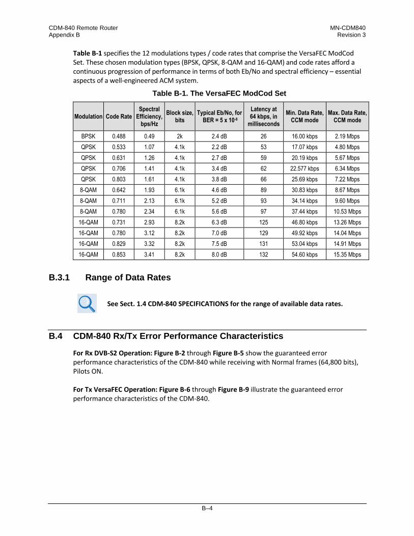
CDM-840 Remote Router MN-CDM840 Appendix B Revision 3
B–4
Table B-1 specifies the 12 modulations types / code rates that comprise the VersaFEC ModCod Set. These chosen modulation types (BPSK, QPSK, 8-QAM and 16-QAM) and code rates afford a continuous progression of performance in terms of both Eb/No and spectral efficiency – essential aspects of a well-engineered ACM system.
Table B-1. The VersaFEC ModCod Set
Modulation Code Rate Spectral
Efficiency, bps/Hz
Block size, bits
Typical Eb/No, for BER = 5 x 10⁻⁸
Latency at 64 kbps, in
milliseconds Min. Data Rate,
CCM mode Max. Data Rate,
CCM mode
BPSK 0.488 0.49 2k 2.4 dB 26 16.00 kbps 2.19 Mbps QPSK 0.533 1.07 4.1k 2.2 dB 53 17.07 kbps 4.80 Mbps QPSK 0.631 1.26 4.1k 2.7 dB 59 20.19 kbps 5.67 Mbps QPSK 0.706 1.41 4.1k 3.4 dB 62 22.577 kbps 6.34 Mbps QPSK 0.803 1.61 4.1k 3.8 dB 66 25.69 kbps 7.22 Mbps 8-QAM 0.642 1.93 6.1k 4.6 dB 89 30.83 kbps 8.67 Mbps 8-QAM 0.711 2.13 6.1k 5.2 dB 93 34.14 kbps 9.60 Mbps 8-QAM 0.780 2.34 6.1k 5.6 dB 97 37.44 kbps 10.53 Mbps 16-QAM 0.731 2.93 8.2k 6.3 dB 125 46.80 kbps 13.26 Mbps 16-QAM 0.780 3.12 8.2k 7.0 dB 129 49.92 kbps 14.04 Mbps 16-QAM 0.829 3.32 8.2k 7.5 dB 131 53.04 kbps 14.91 Mbps 16-QAM 0.853 3.41 8.2k 8.0 dB 132 54.60 kbps 15.35 Mbps
B.3.1 Range of Data Rates
See Sect. 1.4 CDM-840 SPECIFICATIONS for the range of available data rates.
B.4 CDM-840 Rx/Tx Error Performance Characteristics
For Rx DVB-S2 Operation: Figure B-2 through Figure B-5 show the guaranteed error performance characteristics of the CDM-840 while receiving with Normal frames (64,800 bits), Pilots ON. For Tx VersaFEC Operation: Figure B-6 through Figure B-9 illustrate the guaranteed error performance characteristics of the CDM-840.

CDM-840 Remote Router MN-CDM840 Appendix B Revision 3
B–5
Figure B-2. DVB-S2 QPSK Packet Error Rate versus Es/No

CDM-840 Remote Router MN-CDM840 Appendix B Revision 3
B–6
Figure B-3. DVB-S2 8PSK Packet Error Rate versus Es/No

CDM-840 Remote Router MN-CDM840 Appendix B Revision 3
B–7
Figure B-4. DVB-S2 16APSK Packet Error Rate versus Es/No

CDM-840 Remote Router MN-CDM840 Appendix B Revision 3
B–8
Figure B-5. DVB-S2 32APSK Packet Error Rate versus Es/No
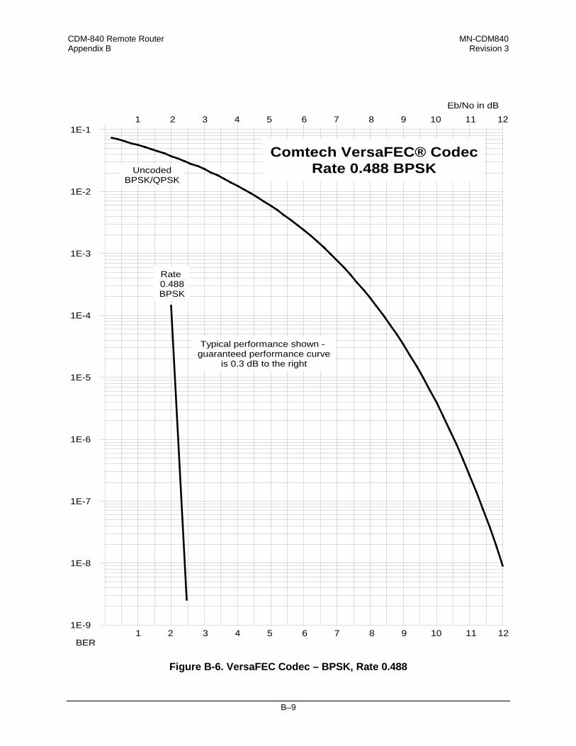
CDM-840 Remote Router MN-CDM840 Appendix B Revision 3
B–9
Figure B-6. VersaFEC Codec – BPSK, Rate 0.488
1E-9
1E-8
1E-7
1E-6
1E-5
1E-4
1E-3
1E-2
1E-11 2 3 4 5 6 7 8 9 10 11 12
Eb/No in dB
UncodedBPSK/QPSK
Comtech VersaFEC® CodecRate 0.488 BPSK
1 2 3 4 5 6 7 8 9 10 11 12BER
Rate 0.488BPSK
Typical performance shown - guaranteed performance curve
is 0.3 dB to the right

CDM-840 Remote Router MN-CDM840 Appendix B Revision 3
B–10
Figure B-7. VersaFEC Codec – QPSK, Rates 0.533, 0.631, 0.706 and 0.803
1E-9
1E-8
1E-7
1E-6
1E-5
1E-4
1E-3
1E-2
1E-11 2 3 4 5 6 7 8 9 10 11 12
Eb/No in dB
UncodedBPSK/QPSK
Comtech VersaFEC® CodecRate 0.533, 0.631, 0.706,
and 0.803 QPSK
1 2 3 4 5 6 7 8 9 10 11 12BER
Rate 0.533QPSK
Typical performance shown - guaranteed performance curves
are 0.3 dB to the right
Rate 0.631QPSK
Rate0.706QPSK
Rate0.803QPSK

CDM-840 Remote Router MN-CDM840 Appendix B Revision 3
B–11
Figure B-8. VersaFEC Codec – 8-QAM, Rates 0.642, 0.711, and 0.780
1E-9
1E-8
1E-7
1E-6
1E-5
1E-4
1E-3
1E-2
1E-11 2 3 4 5 6 7 8 9 10 11 12
Eb/No in dB
UncodedBPSK/QPSK
Comtech VersaFEC® CodecRate 0.642, 0.711, 0.780
8-QAM
1 2 3 4 5 6 7 8 9 10 11 12BER
Rate0.711
8-QAM
Rate0.642
8-QAM
Typical performance show -guaranteed performance curves
are 0.3 dB to the right
Uncoded8-PSK
Rate0.780
8-QAM

CDM-840 Remote Router MN-CDM840 Appendix B Revision 3
B–12
Figure B-9. VersaFEC Codec – 16-QAM, Rates 0.731, 0.780, 0.829 and 0.853
1E-9
1E-8
1E-7
1E-6
1E-5
1E-4
1E-3
1E-2
1E-11 2 3 4 5 6 7 8 9 10 11 12
Eb/No in dB
Rate0.780
16-QAM
Uncoded BPSK/QPSK
Typical Performance shown - guaranteed performance curves
are 0.3dB to the right
Rate0.731
16-QAM
1 2 3 4 5 6 7 8 9 10 11 12BER
Comtech VersaFEC® CodecRate 0.731, 0.780, 0.829
and 0.853 16-QAM
Uncoded 16-QAMRate0.829
16-QAM
Rate0.853
16-QAM

C–1
Appendix C. DATA COLLECTION
C.1 Data Collection Overview
This appendix provides you with the necessary steps that you must follow to collect diagnostic information from an onsite (field-installed) CDM-840 Remote Router. Should you experience an operational issue (such as degraded performance or loss of IP access), it is mandatory that you collect this diagnostic information from the onsite unit in question before contacting Comtech EF Data Product Support. Comtech EF Data can then use this information to properly investigate and resolve the issue. The procedures described here require that you use a user-supplied, Windows-based PC, equipped with a user-supplied terminal emulation program (e.g., Tera Term or HyperTerminal), and a custom Serial Adapter Cable1 C.2 to connect your User PC to the CDM-840. See Sect. for details about your initial setup requirements. Once you are properly configured for data collection, you must do these steps, in this order
:
1. Sect. C.3 instructs you to obtain pre-reboot information* from the onsite CDM-840. You will use your User PC terminal emulator to perform a text capture. Use the emulator to access the CDM-840 Serial Interface, for serial communication between the CDM-840 and your User PC. An example of the Serial Interface is shown here (your firmware revision letter and version number may differ):
* You must gather this information while the issue exists. Do not reboot the CDM-840 for any reason until otherwise instructed in this appendix.
1 See Sect. C.5 in this appendix for the specifications required to fabricate the Serial Adapter Cable that must be provided by the user for use in this procedure.

CDM-840 Remote Router MN-CDM840 Appendix C Revision 3
C–2
2. Once you gather this initial pre-reboot information, you must reboot the CDM-840 to re-initialize and restore service.
3. Once you collect the pre-reboot Serial Interface text capture file, and after the CDM-840 reboots, Sect. C.4 instructs you to you must retrieve the modem’s onboard data collection files via Ethernet connection, and transfer these files to your User PC:
• The “cdm840slot0.xml” file, which contains the CDM-840 modem configuration
settings;
• The “log0”, “log1”, and “log2” files, which contain debug information.
• The “demodulator.log” and “modulator.log” files, which contain traffic information. 4. Assuming that your User PC is equipped with the appropriate Internet access and e-mail
capabilities (Internet Explorer, for example), you must e-mail these pre- and post-reboot files to Comtech EF Data Product Support for evaluation.

CDM-840 Remote Router MN-CDM840 Appendix C Revision 3
C–3
C.2 Initial Setup of Communications Between the CDM-840 and the User PC
CAUTION – Obey precautions for handling electrostatic-sensitive devices.
Do these steps, in this order
:
1. Connect the custom Serial Adapter Cable between the CDM-840 “CONSOLE” port and an available RS-232 serial port on your User PC.
2. Connect a CAT5 Ethernet cable between CDM-840 “ETHERNET | MANAGEMENT | FE” port and an available Ethernet network RJ-45 port on your User PC.
3. Use your terminal emulator program to configure the serial port communication and terminal display operation as follows:
• 38400 bps (Baud Rate) • 8 Data Bits • 1 Stop Bit
• Parity = NO • Port Flow Control = NONE • Display New line Rx/Tx: CR • Local Echo = ON
4. After you properly set up communications between your User PC and the CDM-840 Serial
Interface, the “->” remote command prompt will display on your terminal emulator.
5. Using Windows Command-line (Start > Run... > cmd.exe), create a folder (directory) named “temp” (or some other easy-to-remember name) on your User PC for placement of the text capture file, CDM-840 configuration file, and the data collection files:
Example: C:\>md temp
6. Set your terminal emulator program to capture the Serial Interface session to a text file. Be
sure to specify your “temp” folder as the destination path for this text file.
Read your terminal emulator program User Guide or Help feature for instructions on configuring the serial port communications and for creating and saving text capture files.
You are now ready to begin pre-reboot collection of diagnostic information from the CDM-840.
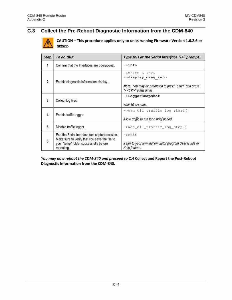
CDM-840 Remote Router MN-CDM840 Appendix C Revision 3
C–4
C.3 Collect the Pre-Reboot Diagnostic Information from the CDM-840
CAUTION – This procedure applies only to units running Firmware Version 1.6.2.6 or newer
.
Step To do this: Type this at the Serial Interface “->” prompt:
1 Confirm that the Interfaces are operational. ->info
2 Enable diagnostic information display.
->Shift 6 <cr> ->display_diag_info Note: You may be prompted to press “enter” and press “y <CR>” a few times.
3 Collect log files. ->LoggerSnapshot Wait 30 seconds.
4 Enable traffic logger. ->wan_dll_traffic_log_start() Allow traffic to run for a brief period.
5 Disable traffic logger. ->wan_dll_traffic_log_stop()
6 End the Serial Interface text capture session. Make sure to verify that you save the file to your “temp” folder successfully before rebooting.
->exit Refer to your terminal emulator program User Guide or Help feature.
You may now reboot the CDM-840 and proceed to C.4 Collect and Report the Post-Reboot Diagnostic Information from the CDM-840.
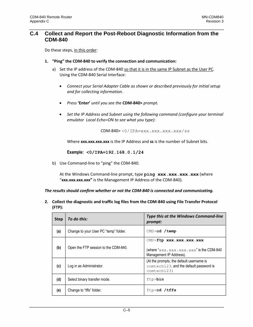
CDM-840 Remote Router MN-CDM840 Appendix C Revision 3
C–5
C.4 Collect and Report the Post-Reboot Diagnostic Information from the CDM-840
Do these steps, in this order
:
1. “Ping” the CDM-840 to verify the connection and communication:
a) Set the IP address of the CDM-840 so that it is in the same IP Subnet as the User PC
. Using the CDM-840 Serial Interface:
• Connect your Serial Adapter Cable as shown or described previously for initial setup and for collecting information.
• Press ‘Enter’ until you see the CDM-840> prompt.
• Set the IP Address and Subnet using the following command (configure your terminal emulator Local Echo=ON to see what you type):
CDM-840> <0/IPA=xxx.xxx.xxx.xxx/ss
Where xxx.xxx.xxx.xxx is the IP Address and ss is the number of Subnet bits. Example: <0/IPA=192.168.0.1/24
b) Use Command-line to “ping” the CDM-840.
At the Windows Command-line prompt, type ping xxx.xxx.xxx.xxx (where “xxx.xxx.xxx.xxx” is the Management IP Address of the CDM-840).
The results should confirm whether or not the CDM-840 is connected and communicating.
2. Collect the diagnostic and traffic log files from the CDM-840 using File Transfer Protocol
(FTP):
Step To do this: Type this at the Windows Command-line prompt:
(a) Change to your User PC “temp” folder. CMD>cd /temp
(b) Open the FTP session to the CDM-840.
CMD>ftp xxx.xxx.xxx.xxx (where “xxx.xxx.xxx.xxx” is the CDM-840 Management IP Address).
(c) Log in as Administrator. (At the prompts, the default username is comtech123, and the default password is comtech123)
(d) Select binary transfer mode. ftp>bin
(e) Change to “tffs” folder. ftp>cd /tffs

CDM-840 Remote Router MN-CDM840 Appendix C Revision 3
C–6
Step To do this: Type this at the Windows Command-line prompt:
(f) Retrieve the CDM-840 configuration file. ftp>get cdm840slot0.xml
(g) Collect the diagnostic log files (they may or may not exist).
ftp>get log0 ftp>get log1 ftp>get log2
(h) Collect the traffic log files. ftp>get demodulator.log ftp>get modulator.log
(j) Terminate the FTP session. ftp>quit
3. Forward the data collection files to Comtech EF Data Product Support: a) Prepare your e-mail describing the operational issue, and address it to Comtech EF Data
Product Support ([email protected]). b) Attach the Serial Interface capture (“cdm840slot0.xml”) and any diagnostic log files
(“log0”, “log1”, “log2”) and traffic log files (“demodulator.log”, “modulator.log”) to your e-mail.
c) Send your e-mail to Comtech EF Data Product Support.
The Data Collection and Reporting Process is now complete.

CDM-840 Remote Router MN-CDM840 Appendix C Revision 3
C–7
C.5 Serial Adapter Cable Fabrication Specifications Reference
CAUTION – The European EMC Directive (EN55022, EN50082-1) requires using properly shielded cables for DATA I/O. To ensure proper operation, fabrication of this Serial Adapter Cable requires that : • You must wire the connectors using the pinout tables and diagram provided
here.
• Type 'D' connectors must have back-shells with continuous metallic shielding.
• Type ‘D’ cabling must have a continuous outer shield (either foil or braid, or both). The shield must be bonded to the connector back-shells.
Description: PC Serial Port Interface User PC Interface End
Cable Connector Type: D-Subminiature DB-9F (Type D-Sub 9-pin Female) Use: For connection to your User PC RS-232 Serial Port
Description: CDM-840 “CONSOLE” Port Interface CDM-840 Onsite Unit Interface End
Cable Connector Type: D-Subminiature DB-9M (Type D-Sub 9-pin Male) Use: For connection to the CDM-840 Onsite Unit “CONSOLE” Port
WIRE LIST / PINOUT WIRE LIST / PINOUT PIN SIG NAME DTE (PC) PIN ASYNCHRONOUS SYNCHRONOUS
1 DCD DATA CARRIER DETECT IN 1 GROUND GROUND 2 RXD RECEIVE DATA IN 2 RS-232 Rx DATA OUT RS-232 Rx DATA OUT 3 TXD TRANSMIT DATA OUT 3 RS-232 Tx DATA IN RS-232 Tx DATA IN 4 DTR DATA TERMINAL READY OUT 4 -- RS-232 Rx CLOCK OUT 5 GND SIGNAL GROUND -- 5 -- RS-232 Tx CLOCK OUT 6 DSR DATA SET READY IN 6 RS-232 Tx DATA ‘B’ IN -- 7 RTS REQUEST TO SEND OUT 7 RS-232 Tx DATA ‘A’ IN -- 8 CTS CLEAR TO SEND IN 8 RS-232 Rx DATA ‘B’ OUT -- 9 RI RING INDICATOR IN 9 RS-232 Rx DATA ‘A’ OUT --

CDM-840 Remote Router MN-CDM840 Appendix C Revision 3
C–8
Notes:

D–1
Appendix D. VERSAFEC RETURN LINK ACM (ADAPTIVE CODING AND
MODULATION) OPTION
D.1 Functional Overview
VersaFEC® is a technology that is wholly owned and developed by Comtech EF Data and Comtech AHA Enterprise Products Group. VersaFEC is a registered trademark of Comtech AHA Enterprise Products Group.
Satellite users have traditionally relied on worst-case link margin to overcome rain fade and other impairments, which leads to significant inefficiencies. ACM (Adaptive Coding and Modulation) allows modulation and code rate (ModCod) to change on a frame-by-frame basis subject to current link conditions. As ACM converts available link margin into increased capacity, average capacity gain of 100% or more is possible. This maximizes each remote’s throughput under all conditions which, in turn, maximizes network efficiency and availability. Advanced VSAT supports ACM in the forward direction as well as the return direction: • With CCM (Constant Coding and Modulation) systems, severe rain fading can cause the total
loss of the link, and zero throughput. ACM keeps the link up (with lower throughput) and can yield much higher system availability.
• ACM turns fade margin into increased link capacity by automatically adapting the modulation type and FEC code rate to give highest possible throughput. Gains of 100% or more are possible, compared to traditional CCM.
• ACM maximizes throughput regardless of link conditions (noise or other impairments, clear sky, rain fade, etc). After initial setup, ACM requires no further user intervention.
You may use ACM with VersaFEC for modems running Firmware Version 1.5.2.X or later.

CDM-840 Remote Router MN-CDM840 Appendix D Revision 3
D–2
D.1.1 Background
ACM has been used for some time in wireless communications, including terrestrial microwave applications and, more recently, over satellite links. The primary function of ACM is to optimize throughput in a wireless data link, by adapting the modulation order used and the Forward Error Correction code rate – both of which directly affect spectral efficiency (expressed in bits per second per Hertz) according to the noise conditions (or other impairments) on the link. Implicit in this concept is that the symbol rate (and power) of the wireless communication system must remain constant. This ensures that the bandwidth allocated for a particular link is never exceeded. Given that the symbol rate does not change, if modulation and coding are changed, the data rate must therefore be modified. This is expressed in the simple equation:
Symbol rate = bit rate / (modulation order * code rate)
For example, for Rate 3/4 QPSK (where modulation order = 2): Symbol rate = bit rate * 0.666
Re-arranging:
Bit rate = symbol rate * modulation order * code rate So, in changing to a higher modulation order or code rate, the bit rate is increased, and in changing to a lower modulation order or code rate, the bit rate is reduced. However, some important factors must be considered: • The digital communications system must be able to tolerate a change in bit rate.
Synchronous serial interfaces (such as G.703 E1, which operated at a fixed data rate of 2.048 Mbps) are totally unsuitable in a scheme where data rate is changing. The only practical application for this scheme is a packet-based scheme that will tolerate a change in data rate, and which has mechanisms within its protocols to recognize when increased or reduced bandwidth is available. The best example of this is Ethernet, and this discussion is limited to schemes that employ it.
The CDM-840 supports both IP and E1 (internally packetized) operation with ACM.
• The bit rate cannot be changed arbitrarily. The link noise conditions, described in terms of Eb/No or SNR, must be able to support reliable communications for the given modulation order and code rate. This is a key point as, in fact, the link SNR is the input that drives the adaptation.

CDM-840 Remote Router MN-CDM840 Appendix D Revision 3
D–3
D.2 VersaFEC ACM
VersaFEC covers a family of 18 short-block LDPC ModCods, specifically designed for low latency and ACM applications. However, the VersaFEC codes are equally well suited to Constant Coding and Modulation (CCM) applications. The shortest possible LDPC codes that give performance at or very close to DVB-S2 with significantly reduced latency in comparison. The family of VersaFEC short-block LDPC codes is presented in Table D-1. The modulation types include BPSK, QPSK, 8-QAM, and 16-QAM. This table shows that, in order to maintain a constant number of symbols per block, the block size in bits (data + parity) must necessarily change, depending on both the modulation type (which affects the number of bits per symbol) and the code rate. For VersaFEC, the block size varies between 2k and 8.2k bits. At worst, therefore, the VersaFEC codes are 50% shorter than the ‘short’ DVB-S2 codes.
Table D-1. The VersaFEC ModCod set
Modulation Code Rate Spectral
efficiency, bps/Hz
Block size, kbits
Typical Eb/No, for
BER = 5 x 10⁻⁸
(dB)
Latency at 64 kbps, in
milliseconds
Min. Data Rate, CCM mode
(kbps)
Max. Data Rate, CCM mode
(Mbps) BPSK 0.488 0.49 2 2.4 26 16.00 2.19 QPSK 0.533 1.07 4.1 2.2 53 17.07 4.80 QPSK 0.631 1.26 4.1 2.7 59 20.19 5.67 QPSK 0.706 1.41 4.1 3.4 62 22.577 6.34 QPSK 0.803 1.61 4.1 3.8 66 25.69 7.22 8-QAM 0.642 1.93 6.1 4.6 89 30.83 8.67 8-QAM 0.711 2.13 6.1 5.2 93 34.14 9.60 8-QAM 0.780 2.34 6.1 5.6 97 37.44 10.53 16-QAM 0.731 2.93 8.2 6.3 125 46.80 13.26 16-QAM 0.780 3.12 8.2 7.0 129 49.92 14.04 16-QAM 0.829 3.32 8.2 7.5 131 53.04 14.91 16-QAM 0.853 3.41 8.2 8.0 132 54.60 15.35
The VersaFEC codes compared with the Shannon bound are shown in Figure D-1. It can be seen that the performance of VersaFEC at or near the DVB-S2 performance with 16 kbit blocks. Note that SNR is used in place of Eb/No, a convention for comparing ACM ModCods. SNR is defined as Eb/No + 10log(Spectral Efficiency).

CDM-840 Remote Router MN-CDM840 Appendix D Revision 3
D–4
Figure D-1. VersaFEC Codes vs. Constrained Capacity
D.2.1 VersaFEC ACM Latency
Examining the data in Table D-2, latency for each ModCod is shown for the example of VersaFEC ACM at a fixed 100 ksymbols/second rate. Of particular note is that even though the ModCods span a 7:1 variation in throughput, the latency is only varying between 25 and 34 milliseconds. In the example shown the worst-case latency for this ACM scheme is 34 milliseconds.
Table D-2. VersaFEC Implementation of ACM – 100 ksymbols/sec Example Case
ModCod Modulation Code Rate Spectral efficiency, bps/Hz Bit rate (throughput) Minimum Latency,
In milliseconds 00 BPSK 0.488 0.49 49 kbps 34 01 QPSK 0.533 1.07 107 kbps 32 02 QPSK 0.631 1.26 126 kbps 30 03 QPSK 0.706 1.41 141 kbps 28 04 QPSK 0.803 1.61 161 kbps 26 05 8-QAM 0.642 1.93 193 kbps 30 06 8-QAM 0.711 2.13 213 kbps 28 07 8-QAM 0.780 2.34 234 kbps 27 08 16-QAM 0.731 2.93 293 kbps 27 09 16-QAM 0.780 3.12 312 kbps 26 10 16-QAM 0.829 3.32 332 kbps 25 11 16-QAM 0.853 3.41 341 kbps 25
OVERALL SYSTEM LATENCY = Worst-case ModCod (ModCod0) Latency = 34 milliseconds, NOT INCLUDING WAN BUFFER OR SATELLITE PATH

CDM-840 Remote Router MN-CDM840 Appendix D Revision 3
D–5
D.3 CDM-840 VersaFEC ACM Operation
The CDM-840 provides several means for configuring VersaFEC ACM operation via Remote Product Control with a user-supplied PC: • CDM-840 HTTP (Web Server) Interface using a compatible Web browser.
• Ethernet-based Simple Network Management Protocol (SNMP) using a Network
Management System (NMS) and Management Information Base (MIB) File Browser.
COMTECH EF DATA RECOMMENDS USE OF THE SERIAL-BASED REMOTE CONTROL INTERFACE AND THE ETHERNET-BASED SNMP INTERFACE ONLY FOR ADVANCED USERS. COMTECH EF DATA STRONGLY ENCOURAGES USE OF THE CDM-840 HTTP INTERFACE FOR MONITOR AND CONTROL (M&C) OF THE CDM-840. THE HTTP INTERFACE FIGURES AS FEATURED THROUGHOUT THIS APPENDIX ARE INTENDED FOR USER REFERENCE ONLY AND ARE SUBJECT TO CHANGE. THE FIRMWARE INFORMATION (I.E., REVISION LETTERS, VERSION NUMBERS, ETC.) AS DISPLAYED MAY DIFFER FROM YOUR SETUP.
D.3.1 VersaFEC ACM Operation Using the HTTP Interfaces
YOU MAY PROCEED WITH ETHERNET-BASED REMOTE PRODUCT MANAGEMENT (HTTP OR SNMP), ASSUMING THAT: • YOUR CDM-840 IS OPERATING WITH THE LATEST VERSION FIRMWARE FILES.
• YOUR CDM-840 IS CONNECTED TO A USER-SUPPLIED, WINDOWS-BASED PC AS
FOLLOWS:
O THE PC SERIAL PORT IS CONNECTED TO THE CDM-840 REAR PANEL ‘CONSOLE’ PORT WITH A USER-SUPPLIED SERIAL CABLE.
O THE PC ETHERNET PORT IS CONNECTED TO THE CDM-840 REAR PANEL ‘ETHERNET | MANAGEMENT | FE’ ETHERNET PORT WITH A USER-SUPPLIED HUB, SWITCH, OR DIRECT ETHERNET CABLE CONNECTION.
O THE PC IS RUNNING A TERMINAL EMULATION PROGRAM (FOR OPERATION OF THE CDM-840 SERIAL INTERFACE) AND A COMPATIBLE WEB BROWSER (FOR OPERATION OF THE HTTP INTERFACE).
• YOU HAVE NOTED THE CDM-840 MANAGEMENT IP ADDRESS USING THE
CDM-840 SERIAL INTERFACE.

CDM-840 Remote Router MN-CDM840 Appendix D Revision 3
D–6
Figure D-2 shows the CDM-840 HTTP Interface “splash” page, and the menu tree for accessing VersaFEC ACM operation. Page functionality that is not specific to VersaFEC ACM operation appears dimmed.
Figure D-2. CDM-840 HTTP Interface and Menu Tree – VersaFEC ACM Operation
(FW Ver. 1.6.2.X)

CDM-840 Remote Router MN-CDM840 Appendix D Revision 3
D–7
Do these steps to configure the CDM-840 for VersaFEC ACM operation from the specified HTTP Interfaces: 1. Configure a route from the CDD-880 to the CTOG-250 for the Management IP Address of the
CDM-840.
• Comtech EF Data CTOG-250 Comtech Traffic Optimization Gateway with CDM-800 Gateway Router Installation and Operation Manual (CEFD P/N MN-CTOG250)
• Comtech EF Data CDD-880 Multi Receiver Router Installation and Operation
Manual (CEFD P/N MN-CDD880)
2. Use the CDM-840 HTTP Interface ‘Configuration | WAN | Mod | ACM’ page (Figure D-3) to configure the Target Es/No margin and the Max ModCod.
Sect. 6.3.3.2.2.2 Configuration | WAN | Mod | ACM (Adaptive Coding and Modulation) in Chapter 6. ETHERNET-BASED REMOTE PRODUCT MANAGEMENT
1) The recommended value for the target margin in order to maintain the link at Ku is at least 0.5db.
2) The Max ModCod should be configured to the maximum ModCod that this terminal can achieve given the link budget, antenna, look angle, BUC power, etc.
3. Enable ACM.
Figure D-3. CDM-840 HTTP Interface – Configuration | WAN | Mod | ACM Page

CDM-840 Remote Router MN-CDM840 Appendix D Revision 3
D–8
D.3.2 Troubleshooting
Confirm that the "Seconds since last LQRM" is being reset to ‘0’ periodically, which indicates that the LQRMs are being received by the CDM-840. Confirm that the proper Management IP Address appears in the CDD_880 Demod screen. It will be populated automatically.
D.3.3 Monitoring ACM Performance
The CDM-840 provides several ways to determine the current state of the ACM system. The current Tx and Rx ModCod, along with the Remote SNR, are displayed on the ‘Configuration | WAN | Mod | ACM’ page (Figure D-3). The SNR displays values between -3.0 dB and +25.0 dB, with a resolution of 0.1 dB. This page updates dynamically, so if a ModCod changes, the parameters are refreshed. This information is also available through the SNMP interface. If you have access to an Oscilloscope in X-Y mode, the CDM-840 rear panel ‘ALARMS’ connector provides analog voltages to monitor the constellation.
D.3.4 ModCod Switch Points
Figure D-4. CDM-840 – ACM ModCod Switch Points
The Figure D-4 graph shows the switch points with the Target Eb/No margin set to 0dB. However, the switch points can be moved (increased) by configuring the Target Eb/No margin

CDM-840 Remote Router MN-CDM840 Appendix D Revision 3
D–9
parameter, which can vary from 0 to 4.5 dB, in 0.5dB steps. In a fading environment, it is strongly recommended to add sufficient margin to maintain an adequate link quality (and to maintain demod lock) during the interval between the Eb/No degrading and the ACM controller responding by lowering the ModCod. See Section D.5 Notes and Recommendations.
D.4 ACM Congestion Control
When the ACM controller switches from a lower to a higher ModCod the bandwidth of the Ethernet link is instantaneously increased. This is not a problem, and the link will adapt to push more packets/second through the link. Conversely, when the ACM controller switches from a higher to a lower ModCod the bandwidth of the Ethernet link is instantaneously reduced. Unless the FIFO in the WAN encapsulator is configured to be very large, the FIFO will tend to overflow, and packets will be lost before the network recognizes that there is congestion, and reduces the rate at which packets are sent. In order to mitigate packet loss when bandwidth is reduced, the CDM-840 ACM system incorporates a method for congestion control that is illustrated in Figure D-5.
Figure D-5. CDM-840 – ACM Congestion Control
The WAN FIFO (the size of which is configurable in the IP Switch setup) produces two control signals that enable and disable the sending of Ethernet Pause Frames. A Pause Frame is an Ethernet frame designed to implement flow control at the MAC layer. A switch supporting 802.3x can send a Pause Frame (with Pause time set to 0xFFFF) to force the link partner to stop sending data. Devices use the Auto-Negotiation protocol to discover the Pause Frame capabilities of the device at the other end of the link. In the diagram it can be seen that when the WAN FIFO reaches a fill state of 87%, it signals the Ethernet Switch to send Pause frames back to the LAN to inhibit the sending of further data. The Pause Frames continue to be sent until the FIFO fill state has reduced to 75%. At this point, normal operation in resumed by sending a Pause Frame with Pause time set to 0x0000. This mechanism has been shown to be very effective at mitigating packet loss when the ACM controller reduces bandwidth.
CDM-840 Remote Router MN-CDM840 Appendix D Revision 3
D–10
D.5 Notes and Recommendations
• VersaFEC is for point-to-point applications. It is required that both directions on the link run in ACM mode, although the symbol rates do not need to be equal. For VersaFEC, if you wish to constrain one direction to run in CCM, simply set the Min and Max ModCod to be equal.
• ACM constitutes a closed-loop control system and it should be remembered that like all control systems, the speed at which the system can react is governed by a number of factors, including the time taken to estimate SNR to the required accuracy, and the transport delay over the satellite. Realistically, it can cope with fading and other link impairments that do not exceed 1 dB/second (more if Target Eb/No margin is increased).
• The ACM controller algorithm that resides in the CDM-840 modem exhibits a different response depending on whether SNR is increasing or decreasing. If the SNR is improving, the ACM controller switches to higher ModCods sequentially until the highest possible ModCod has been reached. It may, therefore, take several seconds for the link to reach maximum throughput. Conversely, if SNR is degrading rapidly (in a fade) then it can change, if needed, directly from ModCod11 to ModCod0 (VersaFEC example). This gives the fastest possible response and helps keep the link intact under fast fading events.
• While ACM can do remarkable things, the fundamentals still apply. Don’t expect the demod to run at a 16-ARY ModCod if the SNR instantaneously drops to 0 dB – the demod will lose lock and the system will recover by switching to ModCod0 (if so configured, in VersaFEC).
To achieve the most robust link performance, Comtech EF Data strongly recommends that you set the Minimum ModCod to 0 (the ModCod of last resort), and set the Unlock Action to ‘Go to minimum ModCod’.
• For VersaFEC running in ACM mode the demodulator is performing blind acquisition – meaning that it has no a priori knowledge of the modulation type or code rate. For this reason the demodulator acquisition time will be slower than in CCM mode. However, the acquisition time is typically under 1 second for all symbol rates and noise conditions.
• Running the ACM link with the Target Eb/No Margin set to 0 dB will give the best utilization of link power, but in conditions of fast fading may cause demod unlock events, or highly degraded BER just prior to the switch to a lower ModCod. In order to mitigate this, we recommend a Target Eb/No Margin of at least 0.5 dB – more if the fading events are particularly severe and/or frequent.
• The BER versus Eb/No performance of the ModCods is identical to the VersaFEC CCM modes described in Appendix B. FEC (FORWARD ERROR CORRECTION) OPTIONS.
• To achieve minimum latency, set the WAN buffer to the smallest practical value This will depend on how well the connected equipment implements rate limiting, and the variation in IP packet size. The default setting is 20 ms.
• All IP features that are available in the CDM-840 (VLAN, QoS, etc) are available while in ACM mode.

CDM-840 Remote Router MN-CDM840 Appendix D Revision 3
D–11
• ACM maximizes throughput not only when Eb/No varies due to atmospheric conditions, but will also mitigate the effects of other impairments, such as antenna pointing error, excessive phase noise and certain types of interference. However, rapidly fluctuating impairments (i.e., ~ less than 1 second) such as scintillation at low antenna look-angles at C-band will generally not be improved by ACM.
D.6 Summary of Specifications
System type Adaptive Coding and Modulation, using BPSK, QPSK, 8-QAM , 16-QAM and VersaFEC short-block LDPC coding - total of 12 ModCods
Symbol Rate Range 16 ksps to 4500 ksps Interface 10/100 BaseT Ethernet, with auto-negotiated Congestion Control
Remote SNR reporting Automatically reported from remote modem – built in function at the physical layer – requires no additional overhead
Max span of data rate 7:1 over range of adaptation Switch point (decreasing SNR) Corresponds to SNR (Es/No) that gives BER = 5 x 10⁻⁸ (margin set to 0 dB) Switch point hysteresis 0.3 dB Max fading rate Approximately 1 dB/second (higher if Target Eb/No margin > 1 dB) Max ModCod update rate 1 update every 2 seconds
Configurable parameters • Minimum and Maximum ModCod (ModCod0 through ModCod11) • Remote Demod Unlock Action: Maintain current ModCod Go to minimum ModCod • Target SNR margin (0 to 4.5 dB, 0.5 dB steps)
System latency 34 milliseconds max (not including WAN buffer, or satellite path)
Monitored parameters
• Tx and Rx ModCods • Local and Remote SNR
(-3.0 dB to +22.0 dB, 0.1 dB resolution, +/- 0.5 dB accuracy) • Config and monitor menus displaying data rate, modulation and code rate update
dynamically with ModCod
Modulation Code Rate Spectral Efficiency, bps/Hz
Typical Eb/No, for BER = 5 x 10⁻⁸
(dB)
Min. Data Rate, ACM mode
(kbps)
Max. Data Rate, ACM mode
(Mbsp)
BPSK 0.488 0.49 2.4 16.00 2.19 QPSK 0.533 1.07 2.2 17.07 4.80 QPSK 0.631 1.26 2.7 20.19 5.67 QPSK 0.706 1.41 3.4 22.577 6.34 QPSK 0.803 1.61 3.8 25.69 7.22 8-QAM 0.642 1.93 4.6 30.83 8.67 8-QAM 0.711 2.13 5.2 34.14 9.60 8-QAM 0.780 2.34 5.6 37.44 10.53 16-QAM 0.731 2.93 6.5 46.80 13.26 16-QAM 0.780 3.12 7.1 49.92 14.04 16-QAM 0.829 3.32 7.7 53.04 14.91 16-QAM 0.853 3.41 8.1 54.60 15.35

CDM-840 Remote Router MN-CDM840 Appendix D Revision 3
D–12
Notes:

E–1
Appendix E. BPM (BRIDGE POINT-TO-MULTIPOINT) OPERATION
E.1 Functional Overview
The overall intent of the Advanced VSAT BPM (Bridge Point-to-Multipoint) feature is to make the Advanced VSAT equipment appear as a “Sky Ethernet Switch”.
This allows for a greatly simplified network deployment.
In BPM Mode, all L2/L3/L4 protocols, such as VLAN, MPLS, IPv6, OSPF, and BGP, flow through the network as they would through an off-the-shelf Ethernet Switch.
Figure E-1. Advanced VSAT BPM “Sky Ethernet Switch”

CDM-840 Remote Router MN-CDM840 Appendix E Revision 3
E–2
E.1.1 BPM Terminology
Term Definition ACM/VCM Adaptive Coding and Modulation / Variable Coding and
Modulation Bridge Mode This Advanced VSAT Network Working Mode configures the Traffic
ports of the CTOG-250 and CDM-840 to function as a Bridge. BPM Mode Bridge Point-to-Multipoint Mode Comtech Dynamic Routing Protocol (CDRP)
CEFD Proprietary protocol that automatically synchronizes the CTOG-250’s Route table with the CDM-840’s LAN connected routes – i.e., the routes that are directed to the LAN ports of the CDM-840.
CTOG-250 Comtech Traffic Optimization Gateway 250. Entry Channel Mode (ECM)
Shared Aloha channel used in Vipersat dSCPC Mode that allows a remote terminal to gain access to the Network.
Flat Network A network in which all devices are directly connected to each other and all devices are on the same IP subnet.
IGMP Internet Group Management Protocol Router Mode This Advanced VSAT Network Working Mode configures the Traffic
ports of the CTOG-250, CDD-880, and CDM-840 to function as a Router.
Single Hop on Demand (SHOD)
This CEFD technology allows for dynamic creation of Single Hop Mesh connections from one CDM-840 to another CDM-840. SHOD requires the Vipersat Management System (VMS).
VLAN Access Mode This mode, only available in the CDM-840, forces the Traffic Interface to carry traffic for only one user-configured VLAN.
VLAN Trunking Mode This is the default mode for BPM, where all packets (with and without VLAN tags) arriving at the CTOG-250 and CDM-840 pass through the system without modification. A trunked port can pass two or more VLANs on the interface.
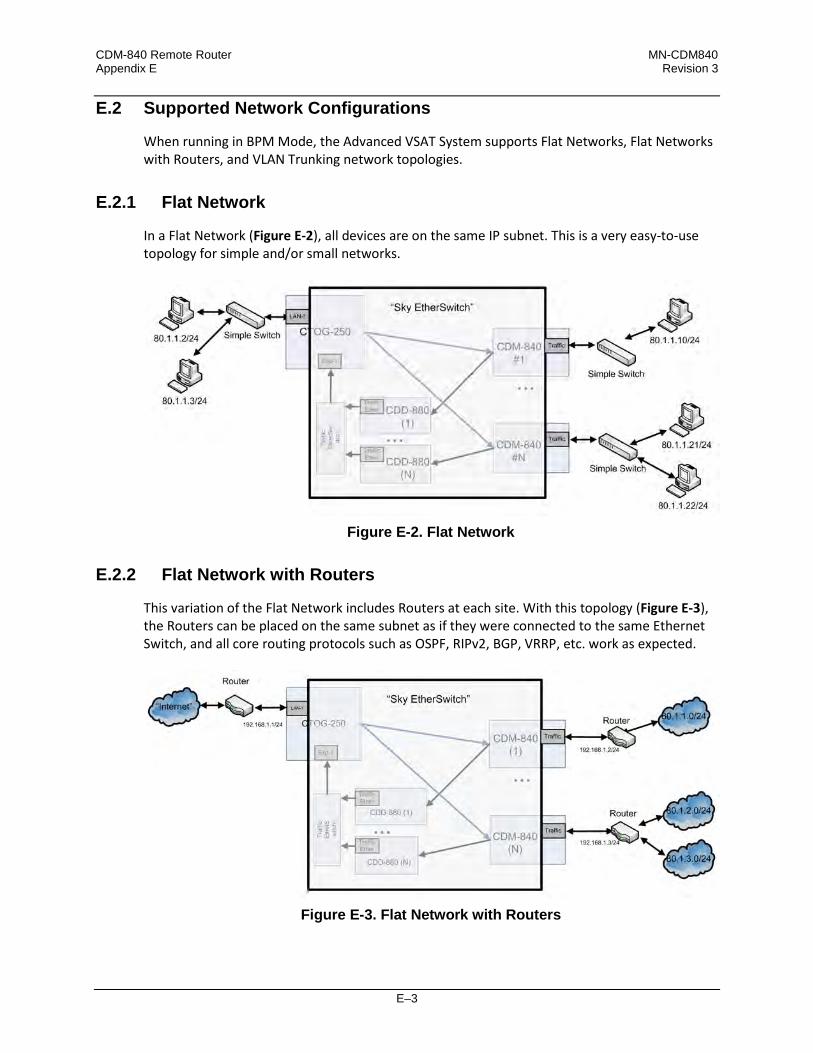
CDM-840 Remote Router MN-CDM840 Appendix E Revision 3
E–3
E.2 Supported Network Configurations
When running in BPM Mode, the Advanced VSAT System supports Flat Networks, Flat Networks with Routers, and VLAN Trunking network topologies.
E.2.1 Flat Network
In a Flat Network (Figure E-2), all devices are on the same IP subnet. This is a very easy-to-use topology for simple and/or small networks.
Figure E-2. Flat Network
E.2.2 Flat Network with Routers
This variation of the Flat Network includes Routers at each site. With this topology (Figure E-3), the Routers can be placed on the same subnet as if they were connected to the same Ethernet Switch, and all core routing protocols such as OSPF, RIPv2, BGP, VRRP, etc. work as expected.
Figure E-3. Flat Network with Routers

CDM-840 Remote Router MN-CDM840 Appendix E Revision 3
E–4
E.2.3 VLAN Trunking
In a VLAN Trunking topology (Figure E-4), the Hub side equipment functions as a VLAN trunking interface. You can map Outbound packets (Hub to Remote) to the desired QoS Group (see Sect. E.6). By default, the CDM-840 Remote Router equipment functions as a VLAN trunk and passes all traffic received on the WAN and Traffic LAN ports. In this mode, you should have a VLAN-enabled Ethernet Switch at each remote to properly break out the VLAN into the desired network topology. In addition, you can optionally configure the CDM-840 in Access Mode with a user assigned VLAN ID (see Sect. E.4).
Figure E-4. BPM with VLANs
E.3 Packet Processing
E.3.1 Traffic Network / Ethernet Switch Behavior
The Advanced VSAT BPM feature functions as a Learning Ethernet Switch when you set the “Working Mode” to BPM. BPM has the following basic functionality: • MAC addresses associated with each segment/port are learned by inspecting the source
MAC for packets arriving at each Ethernet port.
• Once the port association for a MAC address is learned, an Ethernet Switch will not transmit Ethernet packets with that MAC address to other segments/ports.

CDM-840 Remote Router MN-CDM840 Appendix E Revision 3
E–5
• Broadcast packets are sent out all interfaces. For Advanced VSAT BPM Mode, it is important to note that the CTOG-250 Comtech Traffic Optimization Gateway and CDM-840s learn MAC addresses and avoid any unnecessary transmission. In BPM Mode, the CDD-880 Multi Receiver Router functions as a receive-only pass-through to the CTOG-250.
E.3.2 Management Network
Note that, while the Advanced VSAT BPM feature supports Bridged Traffic ports, the Management ports for all units in the Advanced VSAT System must operate in Router Mode. When in BPM Mode, the Traffic ports on the Advanced VSAT units do not have IP Addresses
(as you would expect from an Ethernet Switch). Therefore, the units cannot be managed (SNMP, Web, Telnet) or pinged from this interface.
Figure E-5. Management Network in BPM Mode
When configuring the CTOG-250 for “BPM” Working Mode, Comtech Dynamic Routing Protocol (CDRP) continues to work as expected to populate the CTOG-250 with the routes required to manage the remote CDM-840s via their Management IP Addresses. Handle the Return Link Routed Management Traffic by entering a default route (0.0.0.0/0 “toWAN”) in the CDM-840’s routing table. As with “Router” Working Mode, you must enable CDRP in order for ACM/VCM on the DVB-S2 Outbound Carrier to work for Management Traffic destined to each remote.
CDM-840 Remote Router MN-CDM840 Appendix E Revision 3
E–6
User traffic on the Traffic ports does not require CDRP, as BPM automatically and seamlessly handles ACM/VCM for this traffic. When operating the network with the Comtech NetVue or Vipersat Management System (VMS), the Advanced VSAT units (CTOG-250/CDM-800, CDM-840, and CDD-880) are managed through the Management Network using the Management Ethernet port and Management IP Addresses.
E.4 IEEE 802.1Q Support
Advanced VSAT support for IEEE 802.1Q includes VLAN Trunking, Access Mode and Multiple VLAN Tagging support.
E.4.1 VLAN Trunking
The Advanced VSAT Hub equipment always functions in VLAN Trunking Mode. Trunking Mode means that Ethernet packets received by the CTOG-250 LAN-1 interface are passed, unchanged and unfiltered, to the appropriate remote modem. Likewise, when the CDM-840 is in Trunking Mode, the VLAN tags are passed, unchanged and unfiltered, through the modem. The CDD-880 is a receive-only pass-through in BPM Mode. As such, it receives the packets from the remotes and passes them to the CTOG-250 for processing and forwarding.
E.4.2 Access Mode Support
As part of 802.1Q support, the CDM-840 supports Traffic port configuration in either Trunk or Access Mode. Access Mode allows the CDM-840 to function as a VLAN edge switch to add and remove VLAN tags to connect a distant end network with other networks. • All packets received at the Traffic Ethernet port are tagged with the assigned Access Port
VLAN ID.
• All packets having the matching VLAN ID that are then received from the WAN have the VLAN tag removed, and the packets are passed out the Traffic LAN port.
• In Access Mode, the CDM-840 drops all packets that already have VLAN tags that it receives at its Traffic LAN port.
• In Access Port Mode, packets that do not have a matching VLAN ID that are received from the WAN are dropped. (Note that this is not normal behavior as, once the MAC addresses have been learned at a given remote, all other remotes will then perform a hardware-level filter on the packets.)

CDM-840 Remote Router MN-CDM840 Appendix E Revision 3
E–7
E.4.3 Multiple VLAN Tagging Support
The Advanced VSAT platform supports processing Ethernet packets with multiple stacked VLAN tags, with the following limitations: • At the CTOG-250, only the outermost VLAN ID is used for mapping to the appropriate QoS
Groups.
• In Trunking Mode, L2 Header Compression only compresses packets with one or two VLAN Headers. Packets with more than two VLAN Headers are allowed to pass, but only the first two VLAN headers will not be compressed.
E.5 Multicast BPM Behavior
In BPM Mode, Multicast packets are forwarded in two directions: • Outbound Path
(CTOG-250 CDM-840): Multicast packets arriving at the CTOG-250 are passed out the WAN to all CDM-840s using the “VCM Only MODCOD” option for the matching QoS Group (based upon VLAN or Subnet).
• Return Link Path
(CDM-840 CDD-880 CTOG-250): Multicast packets arriving into the CDM-840 Traffic port are automatically passed out the CTOG-250’s Traffic port only. Internet Control messages (such as OSPF, RIP, and BGP) that fall into the 224.0.0.0 - 224.0.1.255 address range are automatically passed out both the CTOG-250’s LAN and WAN ports.
Figure E-6. Multicast Behavior in BPM Mode

CDM-840 Remote Router MN-CDM840 Appendix E Revision 3
E–8
If required, you can create QoS rules with “Filter All” enabled to filter undesired Multicast from traversing the satellite network for both the CTOG-250 and the CDM-840.
E.5.1 Multicast Management/Routed Behavior (No Change)
In both BPM and Router Modes, Multicast packets arriving at the Management (routed) port of the CTOG-250 and CDM-840 must be configured to be transmitted to the WAN by adding a Multicast-specific route table entry with a “/32” subnet. Packets arriving at the CDM-840 downlink pass out the CDM-840 Ethernet Traffic port based upon the following criteria (configurable via NetVue or the HTTP (Web Server) page for each CDM-840): • Downlink (outbound from the Hub Segment) Multicast All – All downlink outbound
Multicast packets pass to the Traffic LAN interface of the CDM-840 unit.
• Use IGMP (Internet Group Management Protocol) – Only remotes that have IGMP clients enabled with the Multicast address pass the Multicast packet to the CDM-840’s LAN port.
E.6 BPM and Group QoS with Outbound ACM/VCM
Figure E-7. Configuring VLAN to QoS Group Mapping (CTOG-250 shown)
ACM/VCM on the Outbound Carrier works with BPM by seamlessly matching packets to the correct remote site. While no configuration is required, you have the ability to first use a VLAN

CDM-840 Remote Router MN-CDM840 Appendix E Revision 3
E–9
ID, and then use a Subnet/Mask, to associate a packet to a QoS Group. This functionality allows you to partition the Outbound Carrier capacity. In BPM Mode, you must define a simple VLAN mapping algorithm to map traffic for a given remote to a single QoS Group and a single VLAN ID. However, in cases where it is desired to the support the same VLAN ID across multiple remotes but continue to map the traffic for a remote to a single QoS Group, you have the ability to assign the same VLAN with different subnet/masks. Once you add a QoS Group, you can add up to 32 VLAN tags and/or 32 Subnet/Masks per QoS Group. Packet-to-QoS Group mapping employs a strict hierarchical matching algorithm:
Incoming Packet Matching criteria No VLAN header Uses the Destination IP Address of the packet to match the
packet to the QoS Group with the user configured Subnet/Mask. The desired QoS Group must not have any VLAN tags.
1 VLAN Tag First match on the QoS Group with the configured VLAN tag. If more than one QoS Group has the packet’s VLAN ID, then the QoS Group with the matching Subnet/Mask will be used. QoS Groups with a different VLAN ID or no VLAN IDs will not be matched.
2 VLAN Tags Same as the 1 VLAN Tag case, but the outermost VLAN tag will be used for matching purposes.
If the packet fails to match on any of the User Configured QoS Groups, the packet is placed into the Default QoS Group for processing.
E.7 Hub Network Configuration
In order for the BPM feature to operate as expected, you must configure the Hub Network as defined here. A standard off-the-shelf Ethernet switch that supports port isolation and MAC learning is required. All ports connected to the CEFD equipment should have MAC learning enabled. There are three basic deployment approaches:
1. A standalone CTOG-250 2. Multiple independent CTOG-250s 3. CTOG-250 redundancy.

CDM-840 Remote Router MN-CDM840 Appendix E Revision 3
E–10
For the standalone CTOG-250 approach, there are no restrictions on the Hub network beyond requiring that you connect the traffic ports for all of the CDD-880s and the CTOG-250 to the same Ethernet Switch.
Figure E-8. Hub Configuration – Standalone CTOG-250, No Redundancy While the Figure E-8 diagram suggests inclusion of the management network portion, it is not strictly required. However, what is strictly required is that the following holds true for all Advanced VSAT deployments: • The Management IP Addresses for all units have IP connectivity to the NetVue and VMS
server’s IP Address.
• CDD-880 management ports must have a packet path to the Management IP Address of the CDM-840s.
• CDM-840s have a packet path to the Management IP Address of the CTOG-250.

CDM-840 Remote Router MN-CDM840 Appendix E Revision 3
E–11
If you have multiple Advanced VSAT outbound carriers at a single Hub, Comtech EF Data recommends the deployment architecture shown in Figure E-9.
Figure E-9. Hub Network Configuration If you have multiple Advanced VSAT outbound carriers at a single Hub, Comtech EF Data recommends the deployment architecture shown in Figure E-10. In this case, there is no need for port isolation for each of the respective outbound networks; however, you MUST configure the “Static CTOG-250 IP” that is found on the CDD-880 ‘Configuration | Network | Working Mode’ web page. Once you set this value, then the CDD-880 is automatically associated with the desired CTOG-250. The CDD-880 and CTOG-250 exchange a proprietary handshake mechanism that

CDM-840 Remote Router MN-CDM840 Appendix E Revision 3
E–12
allows the packets coming from the CDD-880s to be associated with the correct CTOG-250, as long as you enable MAC learning on the attached Ethernet Switch.
Figure E-10. Multiple CTOG-250 Outbounds in Redundant Mode

CDM-840 Remote Router MN-CDM840 Appendix E Revision 3
E–13
E.8 Compatible Features and Detailed Specifications
Advanced VSAT BPM Mode is compatible with the following features:
Group QoS (CTOG-250) and Return QoS (CDM-840) Header Compression Includes the following L2 Protocols:
• Ethernet 2.0 • Ethernet 2.0+VLAN-tag
• Ethernet 2.0+VLAN-tag+VLAN-tag • Ethernet 2.0+MPLS
• 802.3-raw • 802.3-raw+VLAN-tag
• 802.3-raw+VLAN-tag+VLAN-tag • 802.3+802.2
• 802.3+802.2+VLAN-tag • 802.3+802.2+VLAN-tag+VLAN-tag
• 802.3+802.2+SNAP • 802.3+802.2+SNAP+VLAN-tag
• 802.3 +802.2+SNAP+VLAN-tag+VLAN-tag • 802.3+802.2+SNAP+MPLS
Includes the following L3/L4 Protocols:
• IP, UDP, TCP, RTP
Payload Compression
PTP (Precision Timing Protocol)
RANOP with E1
dSCPC with VMS
ECM (Entry Channel Mode)
AES-128
Return Link ACM
ACM/VCM on the Outbound
Comtech Dynamic Routing Protocol (for the management network)
Multicast
IPv6 (traffic ports only)
VLAN trunking
VLAN Access Mode on the CDM-840 The following features are not
supported when in BPM Mode:
• The standalone CDM-800* does not support BPM due to packet per second limitations.
• Single Hop-on-Demand (SHOD) Mesh.
• CDD-880 Port Diversity.
*Starting with Firmware Ver. 1.5.1.X, the CDM-800 no longer supports standalone mode. The CDM-800 must be paired with a CTOG-250.

CDM-840 Remote Router MN-CDM840 Appendix E Revision 3
E–14
The Advanced VSAT BPM Working Mode has the following detailed specifications:
Attribute Value Comments Maximum Ethernet Frame Size 2018 Bytes Includes FCS but not the preamble Working Mode Routing or BPM All units in the network MUST be
configured the same. All units in the network must be configured to “BPM” for BPM to function as expected.
Traffic port Bridge in BPM Mode Routed in Router Mode
Manage Port Always in Router Mode (not configurable)
Applies to CTOG-250, CDM-840, CDD-880
VLAN Access Mode Support CDM-840 will support VLAN Access Mode for a single VLAN ID.
Access Port VLAN ID = 1..4095
WAN Labels 1-2047 Must be unique across all CDM-840s that shared a CTOG-250 Outbound Carrier. WAN Labels seamlessly provide hardware level filtering to improve network performance.
E.9 Summary
The Advanced VSAT Bridge Point-to-Multipoint feature and functionality enables the support of network architectures requiring IEEE 802.1Q Standards in a number of simple yet powerful network deployments. This is made possible, beginning with Advanced VSAT Firmware Version 1.5.X.X, while taking advantage of all of the features and benefits of the Advanced VSAT Solutions platform.

F–1
Appendix F. CARRIER ID (DVB-CID METACARRIER®)
F.1 Functional Overview
The CDM-840 Remote Router incorporates patent pending carrier identification (CID) technique that uses MetaCarrier® spread spectrum technology to embed a unique carrier identification sequence for the transmitted carrier. The CDM-840 with MetaCarrier® is used in tandem with the Comtech EF Data MCDD-100 MetaCarrier® Detection Device to provide a complete MetaCarrier embedding and decoding solution. Since the initial release of this technology, the European Telecommunications Standards Institute (ETSI) has adopted a modified version of Comtech’s original scheme, which is defined in ETSI TS 103 129 – Digital Video Broadcasting (DVB) Framing Structure, Channel Coding and Modulation of a Carrier Identification System (DVB-CID) for Satellite Transmission. CDM-840s running Firmware Version 1.6.2.4 or later fully comply with this new ETSI specification.
F.1.1 About MetaCarrier
The DVB-CID (MetaCarrier) concept employs a low-speed data sequence containing identifying information about a host carrier that is spread using Direct Sequence Spread Spectrum (DSSS), and then combined, at a low power level, directly underneath that host carrier. The composite signal therefore carries its own embedded identification. The power level and bandwidth of the MetaCarrier is sufficiently low that it is completely hidden below the host carrier, and has minimal effect on system Eb/No (approximately 0.1 dB). DVB-CID operates independent of the modulation and Forward Error Correction (FEC) rate of the host carrier. In configurations where the carrier is encrypted or uses cryptographic technologies, the information carried in the DVB-CID is not affected. Traditionally, the method for identifying an interfering carrier involves using a geo-location system that, in turn, uses the phase offset from an adjacent satellite to triangulate the approximate location on the surface of the earth where the interference is being generated. While such “tried-and-true” geo-locating methods have proven beneficial to satellite operators and service providers, they are nevertheless imprecise. For example, to find the exact location

CDM-840 Remote Router MN-CDM840 Appendix F Revision 3
F–2
of the transmission source in a densely populated area, you must dispatch a helicopter equipped with a feed horn and spectrum analyzer; the time and cost associated with such methods are significant. By contrast, Comtech EF Data’s DVB-CID provides you with the interference source’s identification information within seconds. Once you identify the offending carrier, you may then contact the uplinking station and request that the station shut down or otherwise remove the identified transmission from service.
F.1.2 Functional Description
In a typical network, there can be many CDM-840s with DVB-CID, and one (or more) MCDD-100 MetaCarrier Detection Devices to verify the presence of the DVB-CID on each carrier. In an interference situation, the MCDD-100 may be used to decode the DVB-CID of an interfering carrier that may not be part of one’s own transmission network, as long as the interfering carrier has an embedded DVB-CID. The CDM-840 creates a composite carrier by first sizing the appropriate MetaCarrier, and then by adding the spread spectrum CID (at a highly reduced power spectral density compared with that of the host carrier). The size of the MetaCarrier is determined based purely on symbol rate and is totally independent of modulation and coding, resulting in two (2) discrete sizes of MetaCarrier being combined with the host carrier. The MetaCarrier parameters are shown below:
Host Carrier Embedded DVB-CID MetaCarrier DVB-CID psd Relative to Host Carrier psd
128 ksps to < 512 ksps 112 kchips per sec * -27.5 dB 512 ksps to < 2048 ksps 224 kchips per sec -27.5 dB 2048 ksps to < 4096 ksps 224 kchips per sec -24.5 dB 4096 ksps to < 8192 ksps 224 kchips per sec -21.5 dB 8192 ksps to 12500 ksps 224 kchips per sec -18.5 dB
*kchips per sec refers to the direct sequence spread spectrum chipping rate As shown here, the bandwidth of the host carrier is always wider than the MetaCarrier, the worst case being a 112 kcps MetaCarrier underneath a 128 ksps host carrier. In all configurations of the combined carrier, the MetaCarrier raises the transmission power less than 0.1 dB above the original carrier.
Note that in accordance with the DVB specification, Carrier ID is only available when the Transmit symbol rate is greater than or equal to 128 ksps.
The CID message is composed of the following information: • CDM-840 MAC Address • Latitude and Longitude • Contact Telephone number • Custom message

CDM-840 Remote Router MN-CDM840 Appendix F Revision 3
F–3
F.2 CDM-840 Carrier ID Operation
Carrier ID operation requires that you first enable Carrier ID feature operation, and then create a MetaCarrier Custom Message. All other parameters (center frequency, symbol rate, and the CDM-840’s MAC address) are set automatically. The CDM-840 provides several means for configuring Carrier ID operation via Remote Product Control with a user-supplied PC: • CDM-840 HTTP (Web Server) Interface using a compatible Web browser.
• Ethernet-based Simple Network Management Protocol (SNMP) using a Network
Management System (NMS) and Management Information Base (MIB) File Browser. • Serial-based Remote Control Interface using a terminal emulation program or Windows
Command-line.
COMTECH EF DATA RECOMMENDS USE OF THE SERIAL-BASED REMOTE CONTROL INTERFACE AND THE ETHERNET-BASED SNMP INTERFACE ONLY FOR ADVANCED USERS. COMTECH EF DATA STRONGLY ENCOURAGES USE OF THE CDM-840 HTTP INTERFACE FOR MONITOR AND CONTROL (M&C) OF THE CDM-840. THE SERIAL AND HTTP INTERFACE FIGURES AS FEATURED THROUGHOUT THIS CHAPTER ARE INTENDED FOR USER REFERENCE ONLY AND ARE SUBJECT TO CHANGE. THE FIRMWARE INFORMATION (I.E., REVISION LETTERS, VERSION NUMBERS, ETC.) AS DISPLAYED MAY DIFFER FROM YOUR SETUP.
F.2.1 CID Operation – CDM-840 HTTP Interface
Chapter 6. ETHERNET-BASED REMOTE PRODUCT MANAGEMENT
YOU MAY PROCEED WITH ETHERNET-BASED REMOTE PRODUCT MANAGEMENT (HTTP OR SNMP), ASSUMING THAT: • YOUR CDM-840 IS OPERATING WITH THE LATEST VERSION FIRMWARE FILES.
• YOUR CDM-840 IS CONNECTED TO A USER-SUPPLIED, WINDOWS-BASED PC AS
FOLLOWS:
O THE PC SERIAL PORT IS CONNECTED TO THE CDM-840 REAR PANEL ‘CONSOLE’ PORT WITH A USER-SUPPLIED SERIAL CABLE.
O THE PC ETHERNET PORT IS CONNECTED TO EITHER THE CDM-840 REAR PANEL ‘ETHERNET | MANAGEMENT | FE’ ETHERNET PORT WITH A USER-SUPPLIED HUB, SWITCH, OR DIRECT ETHERNET CABLE CONNECTION.

CDM-840 Remote Router MN-CDM840 Appendix F Revision 3
F–4
O THE PC IS RUNNING A TERMINAL EMULATION PROGRAM (FOR OPERATION OF THE CDM-840 SERIAL INTERFACE) AND A COMPATIBLE WEB BROWSER (FOR OPERATION OF THE HTTP INTERFACE).
• YOU HAVE NOTED THE CDM-840 MANAGEMENT IP ADDRESS USING THE
CDM-840 SERIAL INTERFACE.
Figure F-1 shows the CDM-840 HTTP Interface “splash” page, and the menu tree diagram for accessing Carrier ID operation. Page functionality that is not specific to CDM-840 Carrier ID operation appears dimmed.
Figure F-1. CDM-840 HTTP Interface and Menu Tree – Carrier ID Operation
(FW Ver. 1.6.2.X)

CDM-840 Remote Router MN-CDM840 Appendix F Revision 3
F–5
To open the Carrier ID page (Figure F-2), click the Utility navigation tab, and then select the CARRIER ID page tab.
Figure F-2. Utility | Carrier ID Page
Carrier ID
• Mgmt MAC Address – This is the read-only MAC Address for the CDM-840’s M&C card.
• Latitude – Set the modem’s physical location in Latitude in the form DDMM.mmC, where: o DD = degrees (00 to 90);
o MM.mm = whole (00 to 60) and fractional (0 to 99 – tenths or hundredths) minutes;
o C = Use the drop-down list to set the compass cardinal point as North or South.
• Longitude – Set the modem’s physical location in Longitude in the form DDDMM.mmC, where: o DDD = degrees (000 through 180);
o MM.mm = whole (00 to 60) and fractional (0 to 99 – tenths or hundredths) minutes;
o C = Use the drop-down list to set the compass cardinal point as East or West.
• Enter a Telephone Number to provide a valid emergency contact number to call to resolve
operational issues – e.g., in case the modulator’s Tx output is causing interference on the satellite. Providing this phone number allows a satellite operator to quickly call the person(s) responsible for correcting any issues.
• Create a Custom Message to provide additional information that may be useful in resolving
operational issues, e.g., to quickly resolve interference. Click [Submit] to save.

CDM-840 Remote Router MN-CDM840 Appendix F Revision 3
F–6
F.2.2 CID Operation – Serial Remote Control
Chapter 7. SERIAL-BASED REMOTE PRODUCT MANAGEMENT
The CDM-840’s serial remote product management interface is an electrical interface that is either an EIA-485 multi-drop bus (for the control of multiple devices) or an EIA-232 connection (for the control of a single device). The interface uses ASCII characters in asynchronous serial form to transmit data between the Controller (e.g., a User PC) and Target (e.g., the modem and ODU). This data consists of control and status information, transmitted in packets of variable length in accordance with the structure and protocol explained in detail in Chapter 7. The Controller is in charge of the process of monitor and control, and is the only device that is permitted to initiate, at will, the transmission of data. Targets are only permitted to transmit when they have been specifically instructed to do so by the Controller. The exchange of information is transmitted, Controller-to-Target and Target-to-Controller, in ‘packets’. Each packet contains a finite number of bytes consisting of printable ASCII characters, excluding ASCII code 127 (DELETE). In this context, the Carriage Return and Line Feed characters are considered printable. With one exception, all messages from Controller-to-Target require a response – this will be either to return data that has been requested by the Controller, or to acknowledge reception of an instruction to change the configuration of the Target.
Controller-to-Target (Issued Command or Query)
Start of Packet Target Address Address Delimiter
Instruction Code Code Qualifier Optional
Arguments End of Packet
< ASCII Code 60
(1 character)
0000 (default)
(4 characters)
/ ASCII Code 47
(1 character)
(3 characters)
= or ? ASCII Codes 61
or 63
(1 character)
(n characters)
Carriage Return ASCII Code 13
(1 character) Packet “issued command” example: <0000/MSG=Comtech EF Data[cr] Packet “issued query” example: <0000/MSG?[cr]
Target-to-Controller (Response to Command or Query)
Start of Packet Target Address Address Delimiter
Instruction Code Code Qualifier Optional
Arguments End of Packet
> ASCII Code 62
(1 character)
0000 (default)
(4 characters)
/ ASCII Code 47
(1 character)
(3 characters)
=, ?, !, *, #, ~ (ASCII Codes 61, 63, 33, 42,
35, or 126) (1 character)
(n characters)
Carriage Return ASCII Code 13
(1 character) Packet example – response received for issued query: >0000/MSG=Comtech EF Data[cr][lf]

CDM-840 Remote Router MN-CDM840 Appendix F Revision 3
F–7
The operands available for Carrier ID configuration and operation through CDM-840 Serial-based Remote Product Management are identified in the following table – details on using these CID-specific remote commands and queries are explicitly defined in Chapter 7.
Operand Description LAT Sets or returns device Longitude. LNG Sets or returns device Latitude. MSG Sets or returns the assigned Custom Message. MUT Sets or returns the mute mode (operational state). PHN Sets or returns the assigned Telephone Number.

CDM-840 Remote Router MN-CDM840 Appendix F Revision 3
F–8
Notes:

G–1
Appendix G. ECM (ENTRY CHANNEL MODE)
G.1 Functional Overview
G.1.1 ECM Terminology
Abbreviation Term Comments
ASR Application Switch Request ASR is a private protocol used by the CDM-840 to request bandwidth from the VMS.
BUC Block Up Converter The BUC is used in the Tx (uplink) of satellite signals to convert a band of frequencies from a lower frequency to a higher frequency.
CDRP Comtech Dynamic Routing Protocol
CDRP is used to simplify the deployment of Comtech EF Data’s Advanced VSAT solution in an IP-routed network.
dSCPC Dynamic Single Channel Per Carrier
dSCPC is a Comtech EF Data FAST Feature used to enable dynamic allocation and sharing of bandwidth among users.
HCC Hub Channel Controller The HCC is a dedicated CDD-880 that generates the TAP and is responsible for all request transactions from each CDM-840 while in Entry Channel Mode.
LNB Low-Noise Block Down Converter The LNB is the receiving device on a parabolic satellite dish used for the Rx (downlink) of satellite signals
RID Remote Identification
The RID is a message, presented to the Hub Channel Controller upon each transmission into the Aloha channel, which contains the IP Address and control flag.
SAS Set of Aloha Slots SAS is used as random access for initial request messaging from the CDM-840s.
SRS Set of Registration Slots SRS is used for time sensitive management message transactions.

CDM-840 Remote Router MN-CDM840 Appendix G Revision 3
G–2
Abbreviation Term Comments
SUM Status Update Message SUM is used for updating VMS device control parameters, such as Tx Frequency, Data Rate, Current MODCOD, Eb/No, Es/No, ACM information, etc.
TAP Transmission Announcement Protocol
The TAP is the time and frequency reference message sent on intervals to synchronize any listening CDM-840s into the Entry Channel.
VMS Vipersat Management System A VMS is a configuration, management, and control tool that is used to configure the Advanced VSAT Network and respond to network anomalies.
G.1.2 ECM Overview
• Comtech EF Data CDD-880 Multi Receiver Router Installation and Operation Manual (CEFD P/N MN-CDD880)
• Comtech EF Data ODM-840 Remote Router / ODMR-840 Reduced Form Factor Remote Router / ODMR-840B Remote Router Board Set Installation and Operation Manual (CEFD P/N MN-ODM840)
Figure G-1 illustrates the processing diagram for ECM (Entry Channel Mode) messaging. ECM is a feature based on slotted Aloha with random retransmission backoff. ECM supports multiple carriers through frequency assignments, which provide simplified deployment and scalability.
Figure G-1. ECM – Message Processing Diagram

CDM-840 Remote Router MN-CDM840 Appendix G Revision 3
G–3
In a typical Comtech EF Data Advanced VSAT System network, the CDD-880 Multi Receiver Router serves as the HCC – Hub Channel Controller – a dedicated hub demodulator selected (mode set) as an ECM controller; Comtech EF Data’s CDM-840 or ODM-840 Remote Router support ECM as an installed component of a typical remote site cluster.
UNLESS OTHERWISE NOTED – This appendix collectively refers to the Comtech EF Data Advanced VSAT Series ODM-840 Remote Router, ODMR-840 Reduced Form Factor Remote Router, and ODMR-840B Remote Router Board Set as the ODM-840.
While a CDM-840 is in Entry Channel Mode, it allows the passing of management traffic only – it will not transmit user data traffic. An ECM-enabled CDM-840 may remain in the entry channel for an extended period if “online” communications are not required, or if dSCPC (Dynamic Single Carrier Per Channel) resources are unavailable. While idle or waiting in the entry channel, the CDM-840 sends periodic health status messages while it continues to service VMS recovery logic timers. Note that a “channel” refers to a fixed carrier slot on the satellite that allows the CDM-840 Remote Router random access (in time) to a readied HCC (CDD-880) for transacting each acquired transmission. Each CDD-880 supports only one Entry Channel; this channel is always assigned to Demod #1. The HCC uses a TAP (Transmission Announcement Protocol) message to broadcast a key subset of transmit parameters that match its receive configuration, but assumes all other site specific parameters were preconfigured at the time of antenna commissioning. In addition, the TAP provides timing information in the form of slot parameters that define the required acquisition time of the receiver and the amount of time allowed for data transmission. The TAP also contains a list of CDM-840s that successfully transmitted during the previous cycle. The list of CDM-840s from which the HCC expected – but did not receive – a response is also provided; these CDM-840s are assigned a slot for the next cycle. Each associated CDM-840 achieves loose time synchronization via the broadcast TAP message transmitted at periodic intervals. Since the TAP transmits via the satellite, all CDM-840s receive it at effectively the same time, with delay differences (due to geographic variation of each remote site cluster) compensated with a specified guard time. Upon receipt of the TAP message, the CDM-840 resets its ECM time reference and uses the slot information to determine/select the next transmit opportunity: • If the CDM-840 has transmitted in the previous cycle, and does not indicate it is finished, it
receives an assigned slot as indicated by its IP Address.
• If the CDM-840 does not have an assigned slot, it randomly picks one from the available contention slots.
• If no contention slots are available, the CDM-840 waits for the next cycle. This process allows each CDM-840 to transmit at a discrete time to minimize the chance of collision. To reduce slot contention further, a random backoff (next slot) algorithm is deployed if the transmission was not received. Each CDM-840 attempts to enter the network by gauging its

CDM-840 Remote Router MN-CDM840 Appendix G Revision 3
G–4
transmissions from this timing reference, randomly picking one of the Set Aloha Slots (SAS) presented by the TAP message. The transmit “on” time is of a fixed duration, allowing sufficient time for the receiving CDD-880 to acquire and pass the management signaling messages. The CDM-840 will continue to attempt access on cadence intervals using random backoffs, selecting a different SAS until receiving positive acknowledgement from the HCC. Upon valid reception, the HCC processes the Remote Identification (RID) packet containing the CDM-840 IP Address, TAP (Group) ID, and ECM state flags. Each CDM-840 sign-on IP Address is added to a list of CDM-840(s) that are queued and await assignment. Depending on the ECM state flag, the CDM-840 either remains idle in the channel or is assigned one of the next available time-sensitive slots. Each slot, labeled as a Set of Registration Slot (SRS), is also assigned through the TAP and allows the CDM-840 to complete any necessary transaction without further contention. The CDM-840 then holds an SRS until it receives its assignment into dSCPC or determines that all necessary transactions are complete; at this time, it releases the slot by signaling the HCC through the RID message. Upon release of the slot, the HCC re-assigns it to the group of contention slots. This cycle repeats until all CDM-840s either have been switched to dSCPC channels or require no further interaction. Once the CDM-840 indicates that registration with VMS is complete (via one of the flags in the RID message), on behalf of the CDM-840 the HCC requests dSCPC assignment by placing the CDM-840 IP Address into the “switch pending” list and sending an ECM type switch request message to the VMS. The VMS, upon receipt, either grants the request and signals the HCC to remove the CDM-840 from its list, or ignores the request and leaves the CDM-840 in the “switch pending” list. The HCC repeats this request at 12-second intervals up to five times before it removes the CDM-840 from the “switch pending” list. While the CDM-840 is in this “switch pending” ECM state, it continues to send SUM health status update messages to the VMS on timed intervals. Since all ECM transmissions from the CDM-840 contain a RID, this causes the CDM-840 to be placed back in the “switch pending” list. This cycle continues until the CDM-840 switches, or is set to ECM ‘Wait’ state, or goes offline. The VMS is the last step in the entry process that provides network registration, and grants or ignores dSCPC resources. If resources are limited because of bandwidth, hardware, or unavailability, the CDM-840s will remain in the entry channel pending assignment.
The VMS plays no role in ECM timing or control.

CDM-840 Remote Router MN-CDM840 Appendix G Revision 3
G–5
G.1.3 CDM-840 ECM Message Processing
Figure G-2 illustrates the internal logic diagram of the remote processing registration message.
Processing Segment Description Remarks Action Remarks
1 ALOHA “Not Registered” or “Reverted”
A Random registration attempts with backoff until in TAP
2 REGISTRATION B In TAP
3 SWITCH PENDING C Complete the registration protocol
4 SWITCHED D Not in TAP
E Registration complete – no more Slots needed
F Received “Switch Command” message from VMS
G Received “Revert” message from VMS
Figure G-2. ECM Message Processing – CDM-840 Remote Router
• The CDM-840s are configured to receive the outbound carrier and are given a TAP (Group) identifier number (default 1) that sets the internal filtering if multiple TAPs are used.
• Upon receipt of the TAP message, the CDM-840 sets modem transmission parameters (if required), initializes timing, and picks at random an SAS to start entry by sending a probe (slot transmission).
• The CDM-840, based on its current ECM state, either requests an assigned slot or waits to be switched:
o An assigned slot request indicates to the HCC if the CDM-840 has more data (e.g.
registration protocol) to send.
o A switch request indicates that the CDM-840 is requesting dSCPC bandwidth. These two flags are independent.

CDM-840 Remote Router MN-CDM840 Appendix G Revision 3
G–6
G.1.4 CDD-880 ECM Message Processing
Figure G-3 illustrates the internal logic diagram of the HCC processing of remote messages.
Processing Segment Description Remarks Action Remarks
1 ALOHA A RID Detected – add to Detection List of TAP
2 TAP In “Assigned Slot” list B RID Detected – add to Detection List of TAP
3 SWITCH PENDING
In “Switch Pending” list – Switch Request sent to VMS up to 5X in 12-second intervals until response
C Missed ‘N’ Consecutive Cycle
4 SWITCHED D Registration complete – no more slots needed
E “Disable” message received from VMS
F CDM-840 received “Revert” message from VMS
Figure G-3. ECM Message Processing – CDD-880 Multi Receiver Router

CDM-840 Remote Router MN-CDM840 Appendix G Revision 3
G–7
G.2 ECM Operational Scenarios
G.2.1 Scenario 1 – VMS Initial Registration Process
For proper registration with the VMS, initialization (power-up and bootup) of the ECM-enabled CDM-840 is required. Upon initialization, the CDM-840: 1. Receives a VMS Announcement, sets up an active VMS IP Address, and initializes ECM TAP
processing;
2. Transmits a registration request using a selected SAS, and sets a “Needs Slot” flag in the RID message;
3. Receives the HCC response, through the TAP, assigning an SRS;
4. Continues to transmit the registration request message in SRS;
5. Receives registration from the VMS (Standard Processing);
6. Transmits a registration acknowledgement to the VMS in SRS – it signals the HCC by clearing “Needs Slot” and sets the “Registered with VMS” and “Need to be Switched” flags in the RID message.
7. Receives the HCC response, through the TAP, as an acknowledgement – the HCC then clears the SRS allocation and sends ECM switch requests to the VMS on behalf of the CDM-840 (Standard Processing);
8. Waits for VMS dSCPC assignment (Standard Processing).
G.2.2 Scenario 2 – Reverted or Auto-Recovered Messages
“Revert” or “Auto Recover” of an already registered CDM-840 is required when: • The CDM-840 was forced into or dropped back to ECM mode;
• The CDM-840 transmits into an SAS setting due to a “Need to be Switched” flag in the RID
message;
• The HCC sends ECM switch requests to the VMS on behalf of the CDM-840 (Standard Processing).
CDM-840 Remote Router MN-CDM840 Appendix G Revision 3
G–8
G.2.2.1 ECM Revert Cycle Timing
When a CDM-840 reverts from dSCPC to ECM, there is typically no wait because the CDM-840 is always monitoring TAP cycles to synchronize. It then randomly selects a slot in the next cycle and transmits. If the probe is not detected at the corresponding CDD-880 (as indicated by the next TAP to the CDM-840), it backs off by doubling the cycle
and selecting another random slot. If the revert happened near the end of the cycle the CDM-840 wait for next TAP.
The ECM TAP cycle duration is designed to be approximately 3 seconds in order to correlate with a recommended VMS message timeout of 5 seconds. This allows the CDM-840 to respond to most VMS requests before the VMS times out and goes into “retry” mode. This optimizes for normal conditions, but may result in slight delays in the event of a catastrophic recovery when a large number of CDM-840s are all trying to transition from ECM to dSCPC mode. The Slots in Frame setting is determined automatically by the HCC, based on the target cycle of 3 seconds and the assigned data rate of the ECM Channel. Essentially, the HCC determines the required acquisition time based on the symbol rate and the data slot time based on the data rate. (Note that only MODCOD 0 (BPSK .488) is supported for ECM so the data rate is approximately half the symbol rate.) These are added to the Guard Band; the result (total time per slot) is divided by 3 seconds, and that result is then rounded up to the next integer number of slots. For example, for a typical Entry Channel at 64 Kbps with a Guard Band of 50 ms, this results in a total of 8 slots per cycle.
G.2.2.2 ECMv2 Backoff Algorithm
The ECMv2 Backoff Algorithm optimizes between quick entry in a quiet network and minimal collisions in an active network. Its key feature is the concept of fixed-length data slots within a repeating frame (or cycle). Each total slot consists of three components: • Acquisition Preamble
• Data Segment for Management Messages
• Guard Band to resolve timing uncertainty An integral number of VersaFEC blocks are used for both the preamble and the data segment; the Guard Band will vary due to system timing uncertainties and propagation delay due to the geographic dispersion of the CDM-840s.
A Guard Band of 50ms is sufficient in most cases to accommodate geographical latency differences and internal timing errors.
The preamble is pre-determined based on calibration tables for receiver acquisition at the current data rate and MODCOD 0 (BPSK .488) (actual value is based on symbol rate; starting with 14 blocks and increasing by 1 block for every 556 ksps). The data segment is sized to support the largest messages needed to complete the Entry Channel handshake protocol and maintain status and CDRP (fixed at 6 VersaFEC blocks (765 bytes)). The actual size (in milliseconds) of each slot is

CDM-840 Remote Router MN-CDM840 Appendix G Revision 3
G–9
therefore a function of the data rate and the number of bits in a VersaFEC block for the ModCod of the ECM channel. When a CDM-840 is ready to transmit, it waits for receipt of a TAP message that establishes time synchronization between all CDM-840s. The TAP message also describes the configuration of the Entry Channel Control receiver. The CDM-840 uses the information in the TAP to configure its own Tx parameters and then checks for available Aloha Slots. If slots are available, it randomly selects one of the available slots.
During heavy use, it is possible that all available slots will be dedicated to CDM-840s that have already initiated the entry handshake although this situation should never last more than two cycles unless there are collisions or degraded link state.
The slot number, multiplied by the total slot length (in milliseconds) provides the start time for transmission, which is always relative to the receipt of the last TAP message.
The total slot length is the sum of the Guard Band, Preamble, and Data Segment that are all provided in the TAP message.
After transmitting its request, the CDM-840 waits for the next TAP message that indicates if that transmission was detected by the Entry Channel Controller. If the transmission is detected, the CDM-840 receives an assigned slot in the current frame and continues to receive assigned slots until it indicates it has completed its entry protocol. If the next TAP does not include an assigned slot, the CDM-840 assumes a collision occurred and begins the backoff algorithm. The backoff is based on contention levels of 2n (where n = 0 to 4; i.e. 2 0=1, 21=2, 22=4, 23=8, and 24=16). The Contention Level always starts at 0, which means the CDM-840 transmits in the next frame when it receives a TAP message. If the transmission is not detected, the CDM-840 goes to Contention Level 1 and picks a random slot in one of the next two frames. If it is still not detected, Contention Level goes to 3 and the CDM-840 randomly picks a slot in one of the next four frames. If the CDM-840 is not detected by Contention Level 4 (16 frames), it then resets to Contention Level 0 and tries again – the CDM-840 uses one random number to select a frame at the current contention level and another random number to select a slot within the frame.
Since the CDM-840s are not aware of each other, their Contention Levels are independent and determined only by when they were initially ready to transmit.

CDM-840 Remote Router MN-CDM840 Appendix G Revision 3
G–10
G.3 ECM Operation
For detailed information, see: • G.1.1 ECM Terminology and G.1.2 Functional Overview in this appendix, for
descriptions of the terms used in this section.
• Chapter 6. ETHERNET-BASED REMOTE PRODUCT MANAGEMENT and Chapter 7. SERIAL-BASED REMOTE PRODUCT MANAGEMENT in this manual.
• Chapter 6. ETHERNET-BASED REMOTE PRODUCT MANAGEMENT and Chapter 7.
SERIAL-BASED REMOTE PRODUCT MANAGEMENT in the CDD-880 Multi Receiver Router Installation and Operation Manual (CEFD P/N MN-CDD880).
• Appendix G. ENTRY CHANNEL MODE SWITCHING in the adjunct CEFD publication
VMS v3.x.x VIPERSAT Management System User Guide (CEFD P/N MN/22156). The CDM-840 and CDD-880 provide several means for configuring ECM operation via Remote Product Control with a user-supplied PC: • Serial-based Remote Control Interface using a terminal emulation program or Windows
Command-line. See Sect. G.3.1.
• CDM-840 and CDD-880 HTTP (Web Server) Interfaces using a compatible Web browser. See Sect.G.3.2.
• Ethernet-based Simple Network Management Protocol (SNMP) using a Network Management System (NMS) and Management Information Base (MIB) File Browser.
COMTECH EF DATA RECOMMENDS USE OF THE ETHERNET-BASED SNMP INTERFACE AND SERIAL-BASED REMOTE CONTROL INTERFACE ONLY FOR ADVANCED USERS. COMTECH EF DATA STRONGLY ENCOURAGES USE OF THE CDM-840 AND CDD-880 HTTP INTERFACES FOR MONITOR AND CONTROL (M&C) OF THE CDM-840 OR CDD-880.
THE SERIAL AND HTTP INTERFACE FIGURES FEATURED THROUGHOUT THIS APPENDIX ARE INTENDED FOR USER REFERENCE ONLY AND ARE SUBJECT TO CHANGE. THE FIRMWARE INFORMATION (I.E., REVISION LETTERS, VERSION NUMBERS, ETC.) AS DISPLAYED MAY DIFFER FROM YOUR SETUP.

CDM-840 Remote Router MN-CDM840 Appendix G Revision 3
G–11
G.3.1 ECM Operation – CDM-840 Serial Remote Control
Chapter 7. SERIAL-BASED REMOTE PRODUCT MANAGEMENT
The CDM-840’s serial remote product management interface is an electrical interface that is either an EIA-485 multi-drop bus (for the control of multiple devices) or an EIA-232 connection (for the control of a single device). The interface uses ASCII characters in asynchronous serial form to transmit data between the Controller (e.g., a User PC) and Target (e.g., the modem and ODU). This data consists of control and status information, transmitted in packets of variable length in accordance with the structure and protocol explained in detail in Chapter 7. The Controller is in charge of the process of monitor and control, and is the only device that is permitted to initiate, at will, the transmission of data. Targets are only permitted to transmit when they have been specifically instructed to do so by the Controller. The exchange of information is transmitted, Controller-to-Target and Target-to-Controller, in ‘packets’. Each packet contains a finite number of bytes consisting of printable ASCII characters, excluding ASCII code 127 (DELETE). In this context, the Carriage Return and Line Feed characters are considered printable. With one exception, all messages from Controller-to-Target require a response – this will be either to return data that has been requested by the Controller, or to acknowledge reception of an instruction to change the configuration of the Target.
Controller-to-Target (Issued Command or Query)
Start of Packet Target Address Address Delimiter
Instruction Code Code Qualifier Optional
Arguments End of Packet
< ASCII Code 60
(1 character)
0000 (default)
(4 characters)
/ ASCII Code 47
(1 character)
(3 characters)
= or ? ASCII Codes 61
or 63
(1 character)
(n characters)
Carriage Return ASCII Code 13
(1 character) Packet “issued command” example: <0000/MSG=Comtech EF Data[cr] Packet “issued query” example: <0000/MSG?[cr]
Target-to-Controller (Response to Command or Query)
Start of Packet Target Address Address Delimiter
Instruction Code Code Qualifier Optional
Arguments End of Packet
> ASCII Code 62
(1 character)
0000 (default)
(4 characters)
/ ASCII Code 47
(1 character)
(3 characters)
=, ?, !, *, #, ~ (ASCII Codes 61, 63, 33, 42,
35, or 126) (1 character)
(n characters)
Carriage Return ASCII Code 13
(1 character) Packet example – response received for issued query: >0000/MSG=Comtech EF Data[cr][lf]

CDM-840 Remote Router MN-CDM840 Appendix G Revision 3
G–12
The operands available for ECM configuration and operation through CDM-840 Serial-based Remote Product Management are identified in the following table – details on using these ECM-specific remote commands and queries are explicitly defined in Chapter 7.
Operand Description EMD Enable or disable ECM Mode operation EBP Configure or query the Tx base power EMI Configure or query the VMS Multicast IP Address EGI Configure or query the ECM Group ID EPH Configure or query the ECM Mode power hunt function ERF Configure or query the Rx LO frequency ETF Configure or query the Tx LO frequency
G.3.2 ECM Operation – HTTP Interfaces
YOU MAY PROCEED WITH ETHERNET-BASED REMOTE PRODUCT MANAGEMENT (HTTP OR SNMP), ASSUMING THAT: • YOU HAVE INSTALLED AND ENABLED THE OPTIONAL VIPERSAT MANAGEMENT
SYSTEM (VMS).
• YOU ARE OPERATING THE CDM-840 WITH THE LATEST VERSION FIRMWARE FILES.
• YOU HAVE CONNECTED THE CDM-840 TO A USER-SUPPLIED, WINDOWS-BASED PC AS FOLLOWS:
O THE PC SERIAL PORT IS CONNECTED TO THE CDM-840 REAR PANEL ‘CONSOLE’
PORT WITH A USER-SUPPLIED SERIAL CABLE.
O THE PC ETHERNET PORT IS CONNECTED TO THE CDM-840 REAR PANEL ‘ETHERNET | MANAGEMENT | FE’ 10/100 FAST ETHERNET M&C PORT WITH A USER-SUPPLIED HUB, SWITCH, OR DIRECT ETHERNET CABLE CONNECTION.
O THE USER PC IS RUNNING A TERMINAL EMULATION PROGRAM (FOR OPERATION OF THE CDM-840 SERIAL INTERFACE) AND A COMPATIBLE WEB BROWSER (FOR OPERATION OF THE CDM-840 HTTP INTERFACE).
• YOU HAVE NOTED THE CDM-840 MANAGEMENT IP ADDRESS USING THE CDM-840 SERIAL INTERFACE.
Figure G-4 shows the CDM-840 HTTP Interface “splash” page, and the menu tree diagram for accessing ECM operation. Page functionality not specific to ECM operation appears dimmed in this diagram.
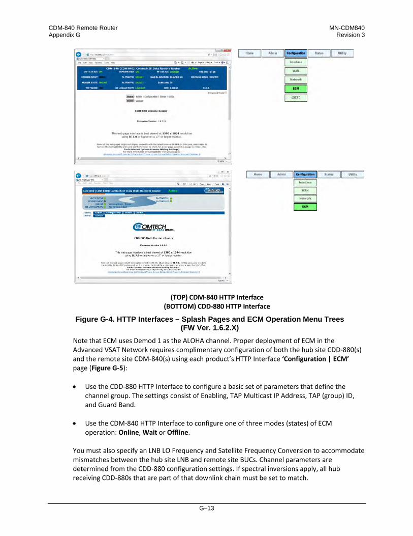
CDM-840 Remote Router MN-CDM840 Appendix G Revision 3
G–13
(TOP) CDM-840 HTTP Interface (BOTTOM) CDD-880 HTTP Interface
Figure G-4. HTTP Interfaces – Splash Pages and ECM Operation Menu Trees (FW Ver. 1.6.2.X)
Note that ECM uses Demod 1 as the ALOHA channel. Proper deployment of ECM in the Advanced VSAT Network requires complimentary configuration of both the hub site CDD-880(s) and the remote site CDM-840(s) using each product’s HTTP Interface ‘Configuration | ECM’ page (Figure G-5): • Use the CDD-880 HTTP Interface to configure a basic set of parameters that define the
channel group. The settings consist of Enabling, TAP Multicast IP Address, TAP (group) ID, and Guard Band.
• Use the CDM-840 HTTP Interface to configure one of three modes (states) of ECM operation: Online, Wait or Offline.
You must also specify an LNB LO Frequency and Satellite Frequency Conversion to accommodate mismatches between the hub site LNB and remote site BUCs. Channel parameters are determined from the CDD-880 configuration settings. If spectral inversions apply, all hub receiving CDD-880s that are part of that downlink chain must be set to match.

CDM-840 Remote Router MN-CDM840 Appendix G Revision 3
G–14
G.3.2.1 CDM-840 HTTP Operation – Remote Router Terminals
Click the Configuration tab, and then the ECM tab to open the page (Figure G-5).
Figure G-5. CDM-840 HTTP Interface – Configuration | ECM Page
ECM Remote Configuration
• Mode: – Use the drop-down list to select operation as Disabled, Offline, Wait, or Online. Each ECM state establishes a different role for the CDM-840 in the overall Advanced VSAT Network operations: o Online – This is the most common ECM state, whereby the CDM-840 powers up,
requests network registration, and switches to dSCPC at the minimum site policy data rate setting.
o Wait – Allowing all CDM-840s in the network to automatically request dSCPC bandwidth
can result in oversubscription, where some percentage of CDM-840s wait their turn for SCPC pooled resources. To avoid oversubscription, the ECM Wait State provides the network operator with the ability to selectively control the CDM-840s through manual, scheduled, or externally switched request commands.
With the CDM-840s set to Wait, they continue to send their health status update messages to the VMS and to the CTOG-250 Comtech Traffic Optimization Gateway (with integrated CDM-800 Gateway Router). The VMS messages update connected link status;

CDM-840 Remote Router MN-CDM840 Appendix G Revision 3
G–15
when dynamic routing mode is enabled, the ACM, CDRP, and data traffic statistics messages sent to the CTOG-250 maintain the forward path ACM and routing tables.
o Offline – In this ECM state, the CDM-840 does not transmit and remains idle until a new
ECM state is selected either locally or from the VMS. Examples for use of this particular ECM state are COTM (communications on the move) or military maneuvers providing radio silence conditions.
Click [Submit] to save.
• Multicast IP: – Enter the IP address for the Multicast of the Transmission Announcement
Protocol (TAP) message that is sent out by the CDD-880 to all of the associated CDM-840s in that group.
• Group ID: (0 to 255) – Enter the Group ID number for the CDD-880 to which this unit belongs.
• Power Hunt Enable: – Use the drop-down list to select this function as Disable or Enable.
When enabled, the transmission power control feature for the unit modulator is activated while in ECM. This function provides compensation during periods of impaired transmission or for instances when the initial (baseline) power value is insufficient, and assists in maintaining return link integrity.
The Power Hunt feature starts with nominal power under ideal conditions, and will probe/listen for a response. If a response is not received, it could be the result of either insufficient power or a collision with another remote. A backoff sequence is attempted and, if there is no response, then the probing sequence is repeated with an increase of Tx output power, in 3dB increments up to a total increase of 9dB.
Appendix M. DPC (VMS DYNAMIC POWER CONTROL)
• Rx LO Frequency: – Assign a value, in MHz, to the Rx LO (Low Oscillator) Frequency.
• Tx LO Frequency: – Assign a value, in MHz, to the Tx LO (Low Oscillator) Frequency.
• ECM Power: (-40.0 to 0.0) – Enter the power level, in dBm, for transmission of the Aloha ECM signal. This level was determined for this unit when its terminal was commissioned, and must be calibrated with the satellite provider.
Click [Submit] to save.
ECM Remote Status
This section provides the following read-only information: • Cycle Length: – The Cycle Length is the total length of time, in milliseconds, between the
start of a transmission and the completion of the transmission cycle (TAP) transmitted by

CDM-840 Remote Router MN-CDM840 Appendix G Revision 3
G–16
the CDD-880 to the CDM-840s in the ECM group. It is the product of the number of slots and the slot length (consisting of the preamble, data slot size, and Guard Band).
• Aloha State: – The Aloha State indicates the current state of this unit during the ECM cycle:
o Idle – The unit is not transmitting; either inactive or waiting for switching assignment.
o Active – The unit is actively transmitting (probing) to the Hub for either registration or request for switching to dSCPC.
o Switched – the Remote has successfully switched from ECM to dSCPC.
• Current Tap: – Indicates current value of sequential progression of TAP message transmission. Ranges from 0 to 255, then repeats.
• Current Slot: – The time slot number that has been assigned to this unit in the transmission cycle for switching from ECM to dSCPC.
This number is only valid for the current cycle and is intended mostly for diagnostic purposes during troubleshooting.
• Home State Revert Timer: – The time, in seconds, that must pass without receiving
communications from the HCC (Hub Channel Controller – i.e., Demod #1 on the CDD-880, the designated ECM controller) TAP message before this unit is reverted from dSCPC mode back to ECM to re-establish communications settings for receiving the TAP. This parameter is set in the VMS.
• Probing Duration: – Amount of time, in seconds, that this unit has been transmitting to the HCC to request registration and switchout.
• Seconds Until Next Probe: – The time period, in seconds, before this unit will again transmit to the HCC.
If this number is greater than 3 seconds, it means that the modem is in backoff mode.
ECM Tx Statistics
Whenever the modem reverts from dSCPC to ECM, the statistics will clear.
This section provides the following read-only information: • Total Count: – This is the total number of transmissions since the modem entered Entry
Channel Mode.
• Successes: – This is the number of successful (entire) transmissions received by the hub.

CDM-840 Remote Router MN-CDM840 Appendix G Revision 3
G–17
• Failures: – This is the number of incomplete transmissions that were detected
by the hub.
• No Detect: – This is the number of transmissions that were undetected
by the hub.
• Last Status: – This displays the status of the most recent transmission as Success, Failure, or No Detect.
• Seconds since last xmit: – This is the number of seconds since the last transmission, regardless of status
G.3.2.2 CDD-880 HTTP Operation – Hub Channel Controller (HCC)
.
Click the Configuration tab, and then the ECM tab to open the page (Figure G-6).
Figure G-6. CDD-880 HTTP Interface – Configuration | ECM Page
ECM Hub Configuration
The acceptable/valid operating ranges for items in this section are provided in parentheses. • Enable: – This feature activates Demod-1 (Rx TRAFFIC 1) on this unit to function as the ECM
Controller for a group of CDM-840s. Use the drop-down list to select operation as Enable or Disable, and then click [Submit] to save.
• Multicast IP: – Enter the IP address for the Multicast of the TAP message that is sent out by this CDD-880 to all of the associated CDM-840s in that group.
• Group ID: (0-255) – Assigning a unique Group ID number to this CDD-880 (i.e., the HCC) and
its associated CDM-840s defines the group of equipment that will respond to the output of the controller. Enter the Group ID number for the CDD-880.

CDM-840 Remote Router MN-CDM840 Appendix G Revision 3
G–18
While “0” is an acceptable assignation, the preferred practical range is from 1 to 255.
• Guard Band: (1-1000) – Enter the Amount of Transmit Off time, in milliseconds, between slots to prevent signal overlap.
• Preamble: – This read-only value identifies the preamble length in VersaFEC frames. • Data Slot Size: – This read-only value identifies the minimum number of Versa FEC blocks in
a data slot. • Slots in Frame: – This read-only value identifies the allowable total number of slots for each
frame. When assigned slots are needed, they are taken from this pool. • Cycle Length: – This read-only value identifies the total cycle length, in milliseconds, of the
TAP message. • LNB LO Frequency: – Assign the LNB LO value, used to send RF frequency values in TAP
messages. Resolution = 100Hz. • Satellite Frequency Conversion: – Assign the correct Satellite Frequency Conversion value,
in MHz, for this hub unit based on the RF equipment used at this site. Click [Submit] to save.
ECM Hub Status (read-only)
• Current Contention slots available – “Contention slots” are the number of time slots in the TAP transmission cycle that are available for assignment to requesting (probing) Remotes.
From left to right:
Column Description Index This is the automatically assigned internal table index number. IP IP address for the identified CDM-840 Remote Router. State Current state of this CDM-840 – one of the following will apply:
• Probing – The unit is requesting service (registration / switching) from the VMS.
• Registered – The unit has been registered with the VMS. • Waiting to switch – the Unit is awaiting dSCPC switch command from the
VMS. Frames Transmitted Count of frames received from this CDM-840. Error Frames Count of frames received with errors from this CDM-840.

CDM-840 Remote Router MN-CDM840 Appendix G Revision 3
G–19
G.3.2.2.1 Tap Message
The TAP message is a standard UDP/IP multicast forward over the outbound channel with a payload containing the following sections: • Standard Vipersat Header (distinguishes TAP from other Vipersat messages)
• Timestamp field (set by CDM-840 [at WAN interface] when TAP is received)
• Aloha Channel Frequency Plan (Frequency, Data Rate, Modulation, and Coding) • Slot and Timing Control
• Lists of CDM-840s with Assigned Slots (previous transmission succeeded / failed)
• List of CDM-840s that have completed their handshake in the last cycle As noted previously, receipt of a TAP causes all listening CDM-840s to synchronize internal transmit timing clock in order to minimize collisions in the Aloha channel.
G.3.2.2.2 HCC Configuration
The TAP IP Address specifies the multicast address that all CDM-840s in the group use to receive the TAP: • Timing as exposed to the user is message interval;
• Total slot count that derives the Cycle Length is set in milliseconds;
• All other parameters are calculated based on current rate;
• The Date Slot Size is fixed at 6, and VersaFEC Blocks and Preamble is computed in
milliseconds based on the specified data rate;
• Guard Band is determined during terminal commissioning.
G.3.2.2.3 Hub Operation
After configuration and initialization, the HCC broadcasts the TAP message on cycle intervals waiting for Aloha channel RID messages. Successful reception of the RID places the indicated CDM-840 IP Address along with its ECM state flag (i.e., Online, Wait, or Offline) into the first queued list. The controller checks the flag to determine next operation. If the ECM state is Online, an SRS is assigned for next TAP processing.
• The CDM-840 receives the TAP with its IP Address in the SRS list and, based on where its
place is in the sequential order, determines the slot assignment. By design convention, assigned slots are at the end of the cycle and whatever remains is used for contention at the

CDM-840 Remote Router MN-CDM840 Appendix G Revision 3
G–20
beginning of the cycle. With the assignment, the CDM-840 transmits management data in its assigned slot and awaits acknowledgment and next assignment.
• After the CDM-840 completes its registration protocol, it releases the active flag in the next RID cycle. At this point, the HCC will remove the processing CDM-840’s IP Address from the list clearing the SRS allocation. If the CDM-840 is not switched out of ECM mode, it will proceed to send a Status Update Message (SUM) every minute (or as configured by VMS during registration) in order to maintain its active status with VMS. Typically, a SUM should only require one transmission unless there is contention, in which case the CDM-840 will go into back-off mode until the CDM-840 received acknowledgment from the HCC that the SUM was successfully transmitted.

H–1
Appendix H. HEADER AND PAYLOAD COMPRESSION
H.1 Functional Overview
Header and Payload Compression are standard features provided in Comtech EF Data’s Advanced VSAT Series group of products, including the CDM-840 Remote Router. The CDM-840 implements Payload Compression via the presence of a GZIP ASIC on the CDM-840 main board. This integrated circuit provides the transmit compression and receive decompression capabilities for maximum throughput and efficiency. With Header Compression, the compression library that is incorporated into the CDM-840 for all IP traffic can reduce 40-byte IP/UDP/RTP headers to as little as one (1) byte, or as little as three (3) bytes for TCP/IP. For Voice-over-IP (VoIP), Header Compression provides bandwidth savings greater than 64%. For example, using an 8kbps G.729E voice codec requires 24 kbps of IP bandwidth once encapsulated into an IP/UDP/RTP datagram. With Comtech EF Data’s Header Compression enabled, the same voice call requires only an approximate 8.5 kbps – a savings of almost 65%. Additionally, bandwidth requirements for typical Web/HTTP traffic can be reduced by 10% or more with TCP/IP Header Compression operation enabled. With Payload Compression, the required satellite bandwidth can be reduced by as much as 40 to 50% based on Calgary Corpus files. The compression algorithm can be applied to all data, SLE, and DVB-S2 header excluded. Compression statistics are fed back to the Quality of Service (QoS) system in order to maximize WAN utilization while maintaining priority, latency, and jitter.

CDM-840 Remote Router MN-CDM840 Appendix H Revision 3
H–2
H.1.1 T raffic Optimization
Traffic optimization through payload compression is provided on the CDM-840 using Comtech AHA Enterprise Products Group compression technology via its installed ASIC. The CDM-840 ostensibly supports a hardware-accelerated compression algorithm based on GZIP, a file format standard where the underlying compression algorithm is called Deflate. Deflate is a compression algorithm that is widely available as an open-source software tool; it does not require the use of a software license. Deflate-compressed blocks are wrapped with a header and footer to become GZIP files. Typically, when a classical, single, general purpose CPU performs GZIP compression, the compression performance is scaled back either to maximize data throughput speeds, or the CPU runs slow. To negate either deficiency, an efficient solution is to offload the compression task to a hardware-based GZIP function, as is accomplished with the CDM-840. Hardware-based GZIP compression offloads lossless data compression and frees up the system’s main CPUs. This allows the compression functions to operate not only independently, but also at much higher data rates if needed. The ASIC takes in uncompressed input data, compresses it, and outputs the data in compressed form. The compression hardware does many tasks in parallel, only offloaded from the central CPUs of the CDM-840. This effectively eliminates the multi-pass and iterative nature typical of a classical, single, general purpose CPU that is over tasked with executing the Deflate algorithm.
H.1.2 C ompres s ion P erformanc e
Compression performance is classically measured by two metrics – size reduction and data throughput: • Size reduction is usually reported as a ratio of the uncompressed original size divided by the
compressed size.
• Data throughput is measured in bytes per second (bps) as measured on the uncompressed side of the GZIP ASIC.
Data complexity has no effect on data throughput. Easy-to-compress data files that compress with a high ratio pass through the co-processor at the same high data rate as very complex data, which achieves lower compression ratios. Table H-1 provides Comtech AHA GZIP compression ratio results as compared with the Calgary Corpus and Canterbury Corpus industry standard file sets and algorithms. The HTML file set is from a collection of Internet dynamic content; LZS (Lempel-Ziv-Stac) compression results are based on publicly available descriptions of the LZS algorithm.

CDM-840 Remote Router MN-CDM840 Appendix H Revision 3
H–3
Table H-2 outlines the comparison the effects of the CTOG specification for current operation, based on a session-based compression for which the current performance specifications are given.
Table H-1. Comtech AHA GZip Performance Comparisons
File Sets Comtech AHA363-PCIe LZS ALDC Calgary Corpus 2.7:1 2.2:1 2.1:1 Canterbury Corpus 3.6:1 2.7:1 2.7:1 HTML 4.4:1 3.4:1 2.65:1
Table H-2. Comtech AHA GZip Performance Specifications Support
Description Specification Number of TX compression sessions supported 64,000 Session history size supported 2048 Granularity of control Per route basis Refresh rate 1 to 600 packets or 1 second whichever comes first
Compatibility Packets compressed by the CDM-840 transmitter will be decompressed without error by the CDM-840 receiver.

CDM-840 Remote Router MN-CDM840 Appendix H Revision 3
H–4
H.2 CDM-840 Header and Payload Compression Operation
The CDM-840 provides several means for configuring Header and Payload Compression Carrier ID operation via Remote Product Control with a user-supplied PC: • CDM-840 HTTP (Web Server) Interface using a compatible Web browser.
• Ethernet-based Simple Network Management Protocol (SNMP) using a Network
Management System (NMS) and Management Information Base (MIB) File Browser. • Serial-based Remote Control Interface using a terminal emulation program or Windows
Command-line.
COMTECH EF DATA RECOMMENDS USE OF THE ETHERNET-BASED SNMP INTERFACE AND SERIAL-BASED REMOTE CONTROL INTERFACE ONLY FOR ADVANCED USERS. COMTECH EF DATA STRONGLY ENCOURAGES USE OF THE CDM-840 AND CDD-880 HTTP INTERFACES FOR MONITOR AND CONTROL (M&C) OF THE CDM-840 OR CDD-880.
THE SERIAL AND HTTP INTERFACE FIGURES FEATURED THROUGHOUT THIS CHAPTER ARE INTENDED FOR USER REFERENCE ONLY AND ARE SUBJECT TO CHANGE. THE FIRMWARE INFORMATION (I.E., REVISION LETTERS, VERSION NUMBERS, ETC.) AS DISPLAYED MAY DIFFER FROM YOUR SETUP.
H.2.1 Compression Operation – CDM-840 HTTP Interface
See Chapter 6. ETHERNET-BASED REMOTE PRODUCT MANAGEMENT for in-depth information about the function and operation of the CDM-840 HTTP Interface.
YOU MAY PROCEED WITH ETHERNET-BASED REMOTE PRODUCT MANAGEMENT (HTTP OR SNMP), ASSUMING THAT: • YOUR CDM-840 IS OPERATING WITH THE LATEST VERSION FIRMWARE FILES.
• YOUR CDM-840 IS CONNECTED TO A USER-SUPPLIED, WINDOWS-BASED PC AS
FOLLOWS:
O THE PC SERIAL PORT IS CONNECTED TO THE CDM-840 REAR PANEL ‘CONSOLE’ PORT WITH A USER-SUPPLIED SERIAL CABLE.
O THE PC ETHERNET PORT IS CONNECTED TO THE CDM-840 REAR PANEL ‘ETHERNET | MANAGEMENT | FE ETHERNET’ 10/100 FAST ETHERNET PORT WITH A USER-SUPPLIED HUB, SWITCH, OR DIRECT ETHERNET CABLE CONNECTION.
O THE PC IS RUNNING A TERMINAL EMULATION PROGRAM (FOR OPERATION OF THE CDM-840 SERIAL INTERFACE) AND A COMPATIBLE WEB BROWSER
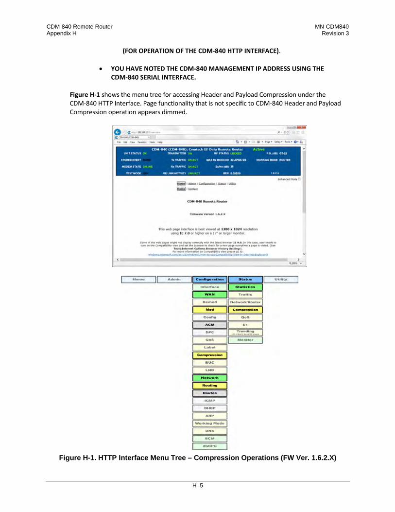
CDM-840 Remote Router MN-CDM840 Appendix H Revision 3
H–5
(FOR OPERATION OF THE CDM-840 HTTP INTERFACE). • YOU HAVE NOTED THE CDM-840 MANAGEMENT IP ADDRESS USING THE
CDM-840 SERIAL INTERFACE.
Figure H-1 shows the menu tree for accessing Header and Payload Compression under the CDM-840 HTTP Interface. Page functionality that is not specific to CDM-840 Header and Payload Compression operation appears dimmed.
Figure H-1. HTTP Interface Menu Tree – Compression Operations (FW Ver. 1.6.2.X)

CDM-840 Remote Router MN-CDM840 Appendix H Revision 3
H–6
H.2.2 E nable or Dis able Header and P ayload C ompres s ion Operation
Use the ‘Configuration | Network | Routing | Routes’ page (Figure H-2) to enable or disable Header and Payload Compression operation when operating in Router Mode.
Figure H-2. Configuration | Network | Routing | Routes Page
When operating in BPM (Bridge Point-to-Multipoint) Mode, use the Bridged Point-to-Multipoint Configuration on the Compression Configuration Page. This will enable and disable the Header and Payload compression for the entire Transmit path. When enabled, the CDM-840 automatically identifies supported packets for Header Compression. The only configurable settings are the Header and Payload Compression Refresh Rates.
Header and Payload Compression is independent from QoS. The enabling or disabling of this feature is required only on the sending Comtech EF Data VSAT products (CDM-840, ODM/R-840, CTOG-250/CDM-800 or standalone CDM-800 for FW Versions V1.5.1 or older). The need to Header and Payload Decompress incoming packets on the ODM/R-840 or CDD-880 is automatic and transparent to the user.
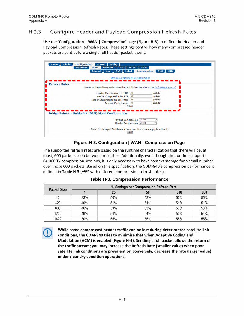
CDM-840 Remote Router MN-CDM840 Appendix H Revision 3
H–7
H.2.3 C onfigure Header and P ayload C ompres s ion R efres h R ates
Use the ‘Configuration | WAN | Compression’ page (Figure H-3) to define the Header and Payload Compression Refresh Rates. These settings control how many compressed header packets are sent before a single full header packet is sent.
Figure H-3. Configuration | WAN | Compression Page
The supported refresh rates are based on the runtime characterization that there will be, at most, 600 packets seen between refreshes. Additionally, even though the runtime supports 64,000 Tx compression sessions, it is only necessary to have context storage for a small number over those 600 packets. Based on this specification, the CDM-840’s compression performance is defined in Table H-3 (±5% with different compression refresh rates).
Table H-3. Compression Performance
Packet Size % Savings per Compression Refresh Rate 1 25 50 300 600
40 23% 50% 53% 53% 55% 420 40% 51% 51% 51% 51% 800 46% 53% 53% 53% 53%
1200 49% 54% 54% 53% 54% 1472 50% 55% 55% 55% 55%
While some compressed header traffic can be lost during deteriorated satellite link conditions, the CDM-840 tries to minimize that when Adaptive Coding and Modulation (ACM) is enabled (Figure H-4). Sending a full packet allows the return of the traffic stream; you may increase the Refresh Rate (smaller value) when poor satellite link conditions are prevalent or, conversely, decrease the rate (larger value) under clear sky condition operations.

CDM-840 Remote Router MN-CDM840 Appendix H Revision 3
H–8
Figure H-4. Configuration | WAN | MOD | ACM Page
H.2.4 V iew Header and P ayload C ompres s ion S tatis tic s
Use the ‘Status | Statistics | Compression’ page (Figure H-5) to review Header and Payload Compression statistics – the total bytes of the pre-compressed and post-compressed traffic and effective compression ratio.
Figure H-5. Status | Statistics | Compression Page

CDM-840 Remote Router MN-CDM840 Appendix H Revision 3
H–9
The CDM-840 supports header compression for Ethernet, and Layer 3, 4, and 5 headers.
The CDM-840 currently supports Router Mode operation only, so Layer 2 headers are not transmitted over the satellite link. Therefore, there is no need for Layer 2 header compression.
Supported Ethernet Headers
• Ethernet 2.0 • 803.3+802.2+SNAP+VLAN tag • 803.3+802.2+SNAP • Ethernet 2.0+MPLS • Ethernet 2.0+VLAN tag • 803.3+SNAP+MPLS • 802.3-raw+VLAN tag • 802.3-raw • 803.3+802.2+VLAN tag • 803.3+802.2
Supported Layer 3 and Layer 4 Headers
• IP • TCP • RTP (Codec Independent) • UDP

CDM-840 Remote Router MN-CDM840 Appendix H Revision 3
H–10
Notes:

J–1
Appendix J. RETURN GROUP QoS (QUALITY OF SERVICE)
J.1 Overview
Quality of Service (QoS) enables a network to use WAN bandwidth more efficiently by managing delay, jitter (delay variation), throughput, and packet loss. The CDM-840 Remote Router provides Return 2-level Group QoS while classifying packets up to Layer 4 (the Transport Layer) of the Open Systems Interconnection (OSI) Model. QoS is fully integrated with ACM (Adaptive Coding and Modulation), dSCPC (Dynamic Single Carrier Per Channel), and header and payload compression to achieve highest bandwidth utilization while providing desired levels of service.
J.1.1 QoS List of Supported RFCs (Requests for Comment)
RFC No. Description
2474 “Definition of the Differentiated Services Field (DS Field) in the IPv4 and IPv6 Headers” Nichols, K., Blake, S., Baker, F. and D. Black, December 1998
2475 “An Architecture for Differentiated Services” Blake, S., Black, D., Carlson, M., Davies, E., Wang, Z. and Weiss, W., December 1998
2597 “Assured Forwarding PHB” Heinanen, J., Baker, F., Weiss, W. and J. Wrocklawski, June 1999
2598 “An Expedited Forwarding PHB” Jacobson, V., Nichols, K. and K. Poduri, June 1999
J.1.2 QoS Terminology
• CIR – CIR (Committed Information Rate) is used to reserve capacity through the QoS system. CIR is entered in kbps but is enforced in 1k Bytes per second increments. The CIR will be honored unless there is not enough bandwidth/symbols on the transmitter.
• CIR Availability – The reported CIRs Availability statistics is the percentage of time over the
last 1, 15 or 60 minutes for which the CIR was demanded of the QoS system and the system was able to honor the packet throughput demand. CIR Availability is intended to provide a metric for operators to trend over time to determine if there is enough satellite bandwidth
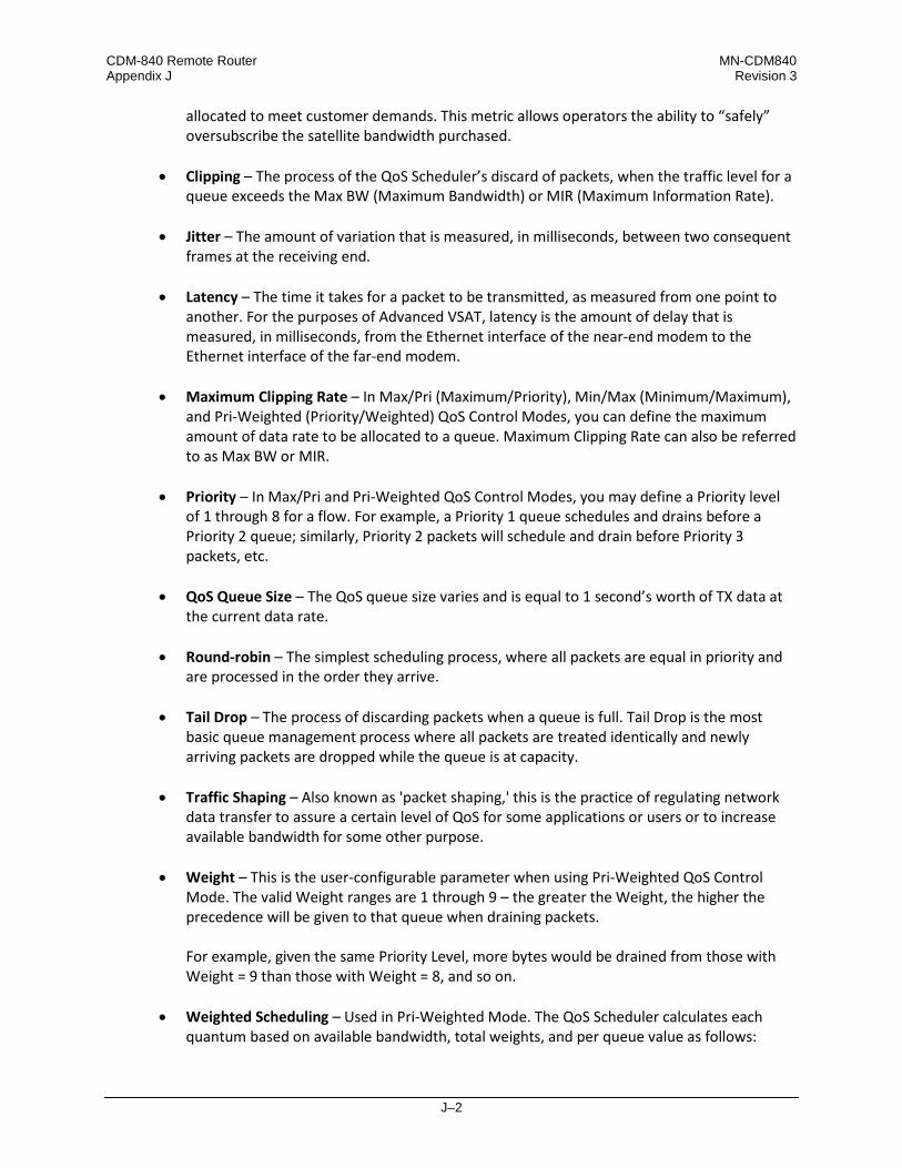
CDM-840 Remote Router MN-CDM840 Appendix J Revision 3
J–2
allocated to meet customer demands. This metric allows operators the ability to “safely” oversubscribe the satellite bandwidth purchased.
• Clipping – The process of the QoS Scheduler’s discard of packets, when the traffic level for a queue exceeds the Max BW (Maximum Bandwidth) or MIR (Maximum Information Rate).
• Jitter – The amount of variation that is measured, in milliseconds, between two consequent frames at the receiving end.
• Latency – The time it takes for a packet to be transmitted, as measured from one point to another. For the purposes of Advanced VSAT, latency is the amount of delay that is measured, in milliseconds, from the Ethernet interface of the near-end modem to the Ethernet interface of the far-end modem.
• Maximum Clipping Rate – In Max/Pri (Maximum/Priority), Min/Max (Minimum/Maximum), and Pri-Weighted (Priority/Weighted) QoS Control Modes, you can define the maximum amount of data rate to be allocated to a queue. Maximum Clipping Rate can also be referred to as Max BW or MIR.
• Priority – In Max/Pri and Pri-Weighted QoS Control Modes, you may define a Priority level
of 1 through 8 for a flow. For example, a Priority 1 queue schedules and drains before a Priority 2 queue; similarly, Priority 2 packets will schedule and drain before Priority 3 packets, etc.
• QoS Queue Size – The QoS queue size varies and is equal to 1 second’s worth of TX data at
the current data rate. • Round-robin – The simplest scheduling process, where all packets are equal in priority and
are processed in the order they arrive. • Tail Drop – The process of discarding packets when a queue is full. Tail Drop is the most
basic queue management process where all packets are treated identically and newly arriving packets are dropped while the queue is at capacity.
• Traffic Shaping – Also known as 'packet shaping,' this is the practice of regulating network
data transfer to assure a certain level of QoS for some applications or users or to increase available bandwidth for some other purpose.
• Weight – This is the user-configurable parameter when using Pri-Weighted QoS Control
Mode. The valid Weight ranges are 1 through 9 – the greater the Weight, the higher the precedence will be given to that queue when draining packets.
For example, given the same Priority Level, more bytes would be drained from those with Weight = 9 than those with Weight = 8, and so on.
• Weighted Scheduling – Used in Pri-Weighted Mode. The QoS Scheduler calculates each quantum based on available bandwidth, total weights, and per queue value as follows:
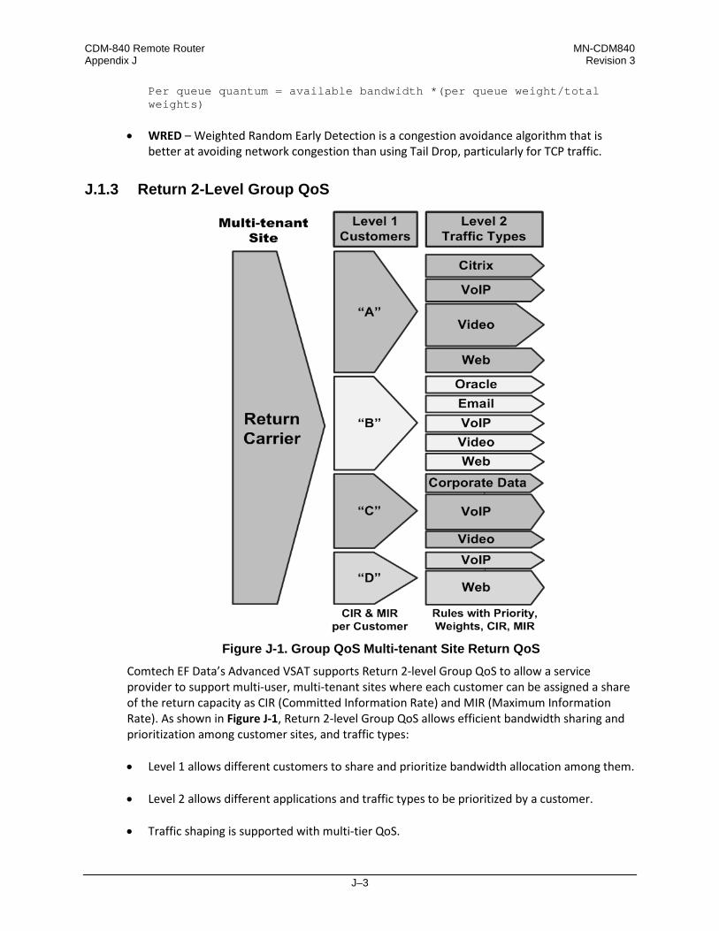
CDM-840 Remote Router MN-CDM840 Appendix J Revision 3
J–3
Per queue quantum = available bandwidth *(per queue weight/total weights)
• WRED – Weighted Random Early Detection is a congestion avoidance algorithm that is
better at avoiding network congestion than using Tail Drop, particularly for TCP traffic.
J.1.3 Return 2-Level Group QoS
Figure J-1. Group QoS Multi-tenant Site Return QoS
Comtech EF Data’s Advanced VSAT supports Return 2-level Group QoS to allow a service provider to support multi-user, multi-tenant sites where each customer can be assigned a share of the return capacity as CIR (Committed Information Rate) and MIR (Maximum Information Rate). As shown in Figure J-1, Return 2-level Group QoS allows efficient bandwidth sharing and prioritization among customer sites, and traffic types: • Level 1 allows different customers to share and prioritize bandwidth allocation among them.
• Level 2 allows different applications and traffic types to be prioritized by a customer. • Traffic shaping is supported with multi-tier QoS.
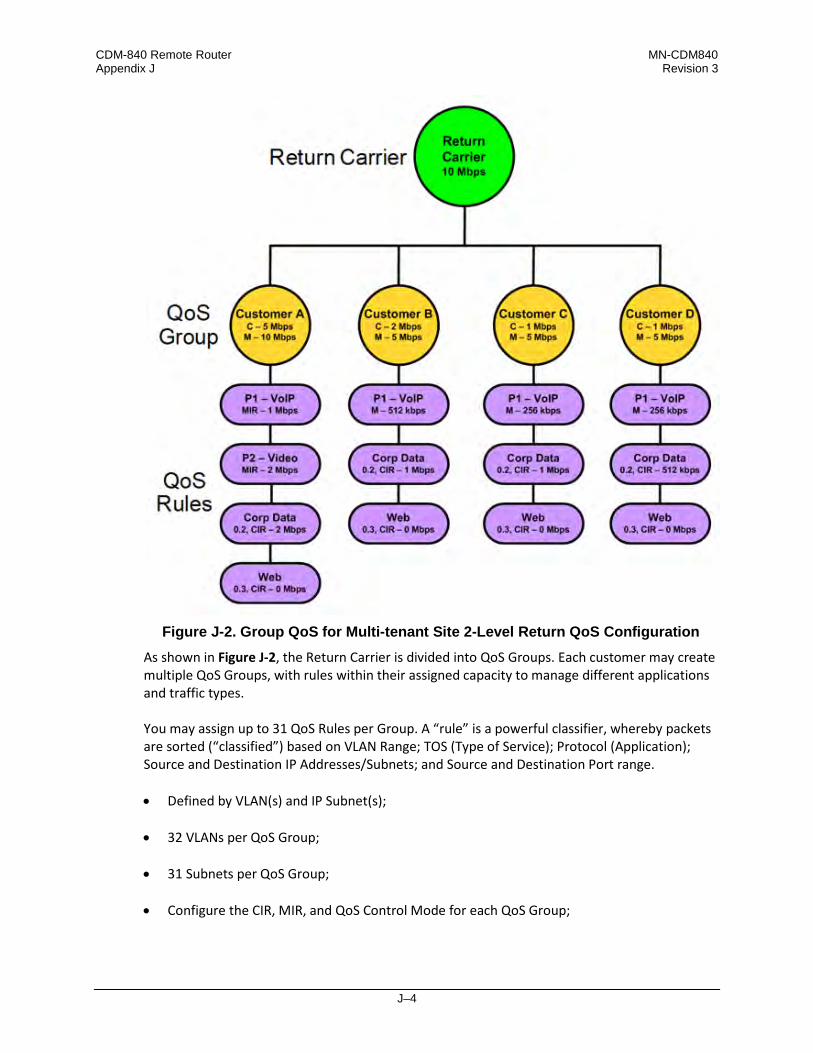
CDM-840 Remote Router MN-CDM840 Appendix J Revision 3
J–4
Figure J-2. Group QoS for Multi-tenant Site 2-Level Return QoS Configuration
As shown in Figure J-2, the Return Carrier is divided into QoS Groups. Each customer may create multiple QoS Groups, with rules within their assigned capacity to manage different applications and traffic types. You may assign up to 31 QoS Rules per Group. A “rule” is a powerful classifier, whereby packets are sorted (“classified”) based on VLAN Range; TOS (Type of Service); Protocol (Application); Source and Destination IP Addresses/Subnets; and Source and Destination Port range. • Defined by VLAN(s) and IP Subnet(s);
• 32 VLANs per QoS Group; • 31 Subnets per QoS Group;
• Configure the CIR, MIR, and QoS Control Mode for each QoS Group;

CDM-840 Remote Router MN-CDM840 Appendix J Revision 3
J–5
• Each QoS Group supports these QoS Control Modes:
o Max/Pri (Maximum/Priority) – Provides multi-level traffic prioritization with the ability to limit maximum traffic per priority class. See Sect. J.2.2.1 for details.
o Min/Max (Minimum/Maximum) – Provides a Committed Information Rate (CIR) to each user defined class of traffic with the ability to allow a higher rate (MIR) depending on bandwidth availability. See Sect. J.2.2.2 for details.
o Pri-Weighted (Priority/Weighted) – Allows for a combination of priorities and weights
with CIR. See Sect. J.2.2.3 for details.
o DiffServ (Differentiated Services) – Industry-standard method that enables seamless co-existence in networks that implement DiffServ. See Sect. J.2.2.4 for details.
• Associates Remotes to QoS Groups for ACM/VCM. An incoming packet is mapped to a QoS Group based on: • Matching Subnet;
• Matching VLAN.
The system collects extensive statistics that can be used to monitor performance in real time, or stored for historical analysis. This includes the entire Return Statistics; QoS Group Statistics; and Per-Rule Statistics. See Sect. J.5 for details.
J.1.4 QoS Operation via Remote Product Control
The CDM-840 provides several means for configuring QoS operation via Remote Product Control with a user-supplied PC: • CDM-840 HTTP (Web Server) Interface using a compatible Web browser.
• Ethernet-based Simple Network Management Protocol (SNMP) using a Network
Management System (NMS) and Management Information Base (MIB) File Browser.
Chapter 6. ETHERNET-BASED REMOTE PRODUCT MANAGEMENT
YOU MAY PROCEED WITH ETHERNET-BASED REMOTE PRODUCT MANAGEMENT (HTTP OR SNMP), ASSUMING THAT: • YOUR CDM-840 IS OPERATING WITH THE LATEST VERSION FIRMWARE FILES.
• YOUR CDM-840 IS CONNECTED TO A USER-SUPPLIED, WINDOWS-BASED PC AS
FOLLOWS:

CDM-840 Remote Router MN-CDM840 Appendix J Revision 3
J–6
O THE PC SERIAL PORT IS CONNECTED TO THE CDM-840 REAR PANEL
‘CONSOLE’ PORT WITH A USER-SUPPLIED SERIAL CABLE.
O THE PC ETHERNET PORT IS CONNECTED TO THE CDM-840 REAR PANEL ‘ETHERNET | MANAGEMENT | FE’ ETHERNET PORT WITH A USER-SUPPLIED HUB, SWITCH, OR DIRECT ETHERNET CABLE CONNECTION.
O THE PC IS RUNNING A TERMINAL EMULATION PROGRAM (FOR OPERATION
OF THE CDM-840 SERIAL INTERFACE) AND A COMPATIBLE WEB BROWSER (FOR OPERATION OF THE HTTP INTERFACE).
• YOU HAVE NOTED THE CDM-840 MANAGEMENT IP ADDRESS USING THE
CDM-840 SERIAL INTERFACE.
• COMTECH EF DATA RECOMMENDS USE OF THE SERIAL-BASED REMOTE CONTROL INTERFACE AND THE ETHERNET-BASED SNMP INTERFACE ONLY FOR ADVANCED USERS. COMTECH EF DATA STRONGLY ENCOURAGES USE OF THE CDM-840 HTTP INTERFACE FOR MONITOR AND CONTROL (M&C) OF THE CDM-840.
Figure J-3 shows the CDM-840 HTTP Interface “splash” page, and the menu tree for accessing the operations specified in this appendix. Page functionality that is not specific to QoS operation appears dimmed.
Figure J-3. CDM-840 HTTP Interface and Menu Tree (FW Ver. 1.6.2.X)

CDM-840 Remote Router MN-CDM840 Appendix J Revision 3
J–7
J.2 QoS Groups
Including the default queue, each QoS Group has up to 32 QoS Rules with eight configurable priorities. The QoS systems: • Create a separate queue for each rule to store the incoming stream of packets. (In this
appendix, ‘QoS rules’ and ‘QoS queues’ are interchangeable.)
• Use a strict priority QoS scheduling algorithm. For QoS Group priority numbering, the lower the priority number, the higher the priority. For example, a Priority 1 queue schedules and drains before a Priority 2 queue; similarly, Priority 2 packets will schedule and drain before Priority 3 packets, etc. Each QoS queue is implemented to support at least one (1)-second burst at the maximum data rate of the Tx Carrier of the modem.
• Incorporate WRED (Weighted Random Early Detection) based congestion avoidance algorithm in addition to tail drop. WRED is designed to avoid congestion by progressively increasing the chance of an incoming packet being dropped once the QoS queue has reached 50% of capacity. After the queue is 50% full, then the random chance of dropping a packet increasing up to 100% when the queue is full.
J.2.1 QoS Group Matching
QoS Group Matching allows you to match an incoming packet to the desired QoS Group. Once a packet has been matched to a QoS Group, then the configured QoS Rule Matching criteria are used to determine where the packet is inserted into the QoS queue. Note that QoS Group Matching is global across all QoS Groups. You must make sure that the QoS Groups throughout the system do not share the same matching criteria The FW Ver. 1.6.2.X Packet-to-QoS Group Matching criteria is as follows (by order of preference): 1. Matching Subnet + VLAN
2. Matching Subnet
3. Matching VLAN
4. Default QoS Group Matching is absolute, not partial. If a QoS Group has a Subnet and VLAN attribute, then the traffic must match BOTH attributes to be classified to use the group. Classification starts with the most stringent matching criteria (Subnet and VLAN) and continues down the hierarchy until a match is found. If there is more than one QoS Group with the same attributes (which should be avoided), the last matching QoS Group will be used.

CDM-840 Remote Router MN-CDM840 Appendix J Revision 3
J–8
J.2.2 QoS Group Control Modes
Chapter 6.3.3.2.3 Configuration | WAN | QoS (Quality of Service) in Chapter 6. ETHERNET-BASED REMOTE PRODUCT MANAGEMENT
Figure J-4. Configuration | WAN | QoS Page Example (Control Mode = Off)
Use the CDM-840 HTTP Interface ‘Configuration | WAN | QoS’ page (Figure J-4) to manage QoS Groups. In the Add/Change/Delete Group section of the page, use the drop-down list to select the desired QoS Control Mode: Max/Pri, Min/Max, Pri-Weighted, or DiffServ. Click [Change] to proceed.
J.2.2.1 QoS Group Max/Pri Control Mode
In Max/Pri Control Mode, you may configure up to 31 QoS rules using VLAN Range, TOS, Protocol (Application), Source and Destination IP Addresses/Subnets, and Source and Destination Port range in order to match packets to the desired QoS rule. For each created rule, you can also set the QoS treatments such as Priority, limiting the Maximum Bandwidth, enable or disable WRED, and enable or disable the FILTER ALL rule. When you enable WRED for a specific queue, QoS randomly drops packets after reaching 50% of the QoS queue capacity. When you enable the FILTER ALL option for a rule, QoS provides the ability to filter the packet completely. In other words, all packets matching the QoS Rule with the FILTER ALL option enabled will be dropped. For example, using the CDM-840 HTTP Interface ‘Configuration | WAN | QoS’ page: 1. Select Max/Pri as the QoS Group Control Mode.
2. Set the Modem Tx bandwidth to 2048 kbps.

CDM-840 Remote Router MN-CDM840 Appendix J Revision 3
J–9
3. Configure the Max/Pri QoS rules as follows:
Index VLAN Range TOS Protocol Src IP/
Mask Dest IP/
Mask
Min Src Port
Max Src Port
Min Dst Port
Max Dst Port
Max BW
(kbps) Priority WRED Filter
All
1 0-4094 255 UDP ***/* ***/* 0 65535 0 65535 644 1 N N 2 0-4094 255 TCP ***/* ***/* 0 65535 0 65535 99999 2 N N 3 0-4094 255 HTTP ***/* ***/* 0 65535 0 65535 99999 3 N N 4 0-4094 255 Def ****/* ***/* 0 65535 0 65535 99999 9 N N
When using the Add/Delete Per Group QoS Rule table, note that QoS Rules match from left to right, with the VLAN Range being the highest match, and the Destination Port range being the lowest match. Matches can be made using multiple attributes.
4. The input data streams are as follows:
Stream VLAN Range TOS Protocol Src
IP/Mask Dest
IP/Mask Src Port Dest Port Stream Data Rate (kbps)
1 0-4094 255 UDP ***/* ***/* *** *** 1024 2 0-4094 255 TCP ***/* ***/* *** *** 1024 3 0-4094 255 HTTP ***/* ***/* *** *** 1024 4 0-4094 255 IP ***/* ***/* *** *** 64
QUESTION: What are the total output data rates and the individual stream data rates?
ANSWER: The individual stream data rates are as follows:
QoS Rule
QoS Group Priority
Input Data Rate (kbps)
QoS Output Data Rate (kbps)
Remain Data Rate (kbps) (After Serving the Priority Queue)
1 1 1024 644 due to max clipping 1404 2 2 1024 1024 380 3 3 1024 380 0 4 9 64 0 0
Total 3136 2048 0

CDM-840 Remote Router MN-CDM840 Appendix J Revision 3
J–10
J.2.2.2 Group Min/Max Control Mode
In Min/Max Control Mode, you may configure up to 31 QoS rules using VLAN Range, TOS, Protocol (Application), Source and Destination IP Addresses/Subnets, and Source and Destination Port range in order to match packets to the desired QoS rule. For each created rule, you can also set the QoS treatment, such as guaranteed minimum bandwidth (Committed Information Rate, or CIR), maximum clipping bandwidth (MIR), enable or disable WRED, and enable or disable the FILTER ALL rule. When you enable WRED for a specific queue, QoS randomly drops packets after reaching 50% of the QoS queue. When you enable the FILTER ALL option for a rule, QoS provides the ability to filter the packet completely. In other words, all packets matching the QoS Rule with the FILTER ALL option enabled will be dropped. For example, using the CDM-840 HTTP Interface ‘Configuration | WAN | QoS’ page: 1. Select Min/Max as the QoS Group Control Mode.
2. Set the Modem Tx bandwidth to 20000 kbps. 3. Configure the Min/Max QoS rules as follows:
Index VLAN Range TOS Protocol
Src IP/
mask
Dest IP/
mask
Min Src Port
Max Src Port
Min Dst Port
Max Dst Port
Min BW
(kbps)
Max BW
(kbps) Priority WRED Filter
All
1 0-4094 255 UDP ***/* ***/* 0 65535 0 65535 2500 4000 8 N N 2 0-4094 255 TCP ***/* ***/* 0 65535 0 65535 2500 99999 8 N N 3 0-4094 255 HTTP ***/* ***/* 0 65535 0 65535 0 99999 8 N N 4 0-4094 255 Def ****/* ***/* 0 65535 0 65535 0 99999 9 N N
When using the Add/Delete Per Group QoS Rule table, note that QoS Rules match from left to right, with the VLAN Range being the highest match, and the Destination Port range being the lowest match. Matches can be made using multiple attributes.
4. The input data streams are as follows:
Stream VLAN Range TOS Protocol Src IP/
Mask Dest
IP/Mask Src Port Dest Port Stream Data Rate (kbps)
1 0-4094 255 UDP ***/* ***/* *** *** 10000 2 0-4094 255 TCP ***/* ***/* *** *** 5000 3 0-4094 255 HTTP ***/* ***/* *** *** 7000 4 0-4094 255 DEF ***/* ***/* *** *** 10000
QUESTION: What are the total output data rates and the individual stream data rates? ANSWER: • In Min/Max QoS Control Mode, other than the default rule (which is configured as Priority
9), all QoS rules are configured at the same priority (Priority 8).

CDM-840 Remote Router MN-CDM840 Appendix J Revision 3
J–11
• In this mode, the minimum bandwidth (CIR) for all rules – excluding the default rule – will be served first in Round-robin fashion.
In this example, the total minimum bandwidth for Rules 1 and 2 is 5000 kbps. Since the total bandwidth is 20000 kbps, it has enough bandwidth to serve. • After serving the minimum bandwidth, the leftover bandwidth is 15000 kbps (20000 – 5000
= 15000).
• Leftover bandwidth will be served among all rules in Round-robin fashion until it hits maximum bandwidth limitations.
• Each rule’s bandwidth is 15000 / 3 = 5000 kbps.
• Since Rule 1 maximum clipping was set to 4000 kbps, and minimum bandwidth has already taken 2500 bytes, it will use 1500 kbps more before reaching the maximum clipping. The leftover 3500 kbps (5000 – 1500 = 3500) is again given to the main pool.
• Rule 2 does not have enough traffic coming in, so it will use only 2500 kbps (5000 – 2500 = 2500); the remaining bandwidth (5000 – 2500 = 2500) is again given to the main pool.
• Rule 3’s input stream is 7000 kbps; it will take its share of the 5000 kbps allocation. Still, it needs 7000 – 5000 = 2000.
• After serving the fair share, the total leftover bandwidth is 6000 kbps (3500 + 2500 = 6000).
• Since Rule 3 needs the bandwidth, the leftover bandwidth is applied to that rule.
• After serving Rule 3, the leftover bandwidth 4000 kbps will be applied to the default queue.
• The default rule will see the data rate of 4000 kbps. The individual rule’s data rates are as follows:
QoS Rule QoS Group Priority Input Data Rate (kbps) QoS Output Data Rate (kbps) 1 1 10000 4000 2 2 5000 5000 3 3 7000 7000 4 9 10000 4000
Total 32000 20000

CDM-840 Remote Router MN-CDM840 Appendix J Revision 3
J–12
J.2.2.3 QoS Group Pri-Weighted Control Mode
In Pri-Weighted Control Mode, you may enter the weight while configuring queues, similar to configuring other parameters such as minimum or maximum bandwidth, priority, etc. In this QoS Control Mode, the weight is considered only if multiple queues are configured with the same priority, and at least one of the weights is different from others and the minimum bandwidth has already been achieved. When valid weights are configured in this QoS Control Mode, the weighted scheduling algorithm is applied. In all other cases, Strict Priority and Round-robin scheduling will be applied.
J.2.2.3.1 Weight
Weight is a user-configurable parameter. The greater the weight, the higher the precedence will be given to that queue when draining the packets. Weight values range from 1 to 9 and 0 is an invalid value. The Scheduler will drain more bytes from weight 9 queues than weight 8 queues under the same priority, and so on.
J.2.2.3.2 Weighted Scheduling
In weighted scheduling mode, the QoS Scheduler calculates each quantum based on available bandwidth, total weights, and per-queue weights as follows: Per queue quantum=available bandwidth*per queue weight/total weights)
There are some exceptions when assigning per-queue quantum to each queue, as represented by three cases: • Case 1 – The per-queue quantum is greater than the configured maximum bandwidth.
When the LAN ingress data rate is greater than the maximum bandwidth, the Scheduler drains packets only up to the maximum bandwidth, and then drops the remaining packets. With Case 1, maximum bandwidth is the limiting factor, and weight is not applied.
• Case 2 – The per-queue quantum is less than the configured maximum bandwidth but more than the configured minimum bandwidth. In this scenario, when the available bandwidth is greater than the total minimum bandwidth but less than total maximum bandwidth, the QoS Scheduler first satisfies the minimum bandwidth for all queues with the same priority, and then divides the remaining bandwidth amongst the queues based on their weight value.

CDM-840 Remote Router MN-CDM840 Appendix J Revision 3
J–13
Case 2 example – The Pri-Weighted QoS rules are configured as follows:
Queue Min BW (kbps) Max BW (kbps) Delta Max Bytes (Max-Min kbps) Weight Allowed BW (kbps)
1 16 32 16 9 – 2 32 64 32 8 – 3 48 128 64 7 – 4 64 64 0 6 –
Total 160 288 112 30 240 The total allowed bandwidth is 240 kbps. The total minimum bandwidth is 160 kbps. The minimum bandwidth is therefore less than the available bandwidth. The QoS Scheduler Calculation Solutions table for the Case 2 example is as follows:
Queue Round 1 Round 2 Round ‘N’ Final
(kbps) Weight Given (kbps)
Leftover (kbps) Weight Given
(kbps) Leftover (kbps) Weight Given
(kbps) Leftover (kbps)
1 9 30 14 – – – – – – 16 2 8 26.672 – 8 7.472 2.144 – – – 32 3 7 23.328 – 7 6.528 – 7 2.144 – 32 4 – – – – – – – – – –
Total 24 80 14 15 14 2.144 7 2.144 0 80 This table shows the result of the steps taken to calculate the individual allocated bandwidths: 1. After the minimum bandwidth is satisfied, there is 80 kbps of bandwidth remaining. This
leftover bandwidth is distributed to all queues whose maximum bandwidth hasn’t been reached. In this example, only Queues 1, 2, and 3 still have an unmet maximum bandwidth.
Since Queue 4’s minimum and maximum bandwidths are the same, Queue 4 will be taken out of the algorithm for distributing the remaining quantum.
The remaining total weight is (9 + 8 + 7) = 24.
2. Each bandwidth share is then calculated based on the remaining total weight (24) and
bandwidth availability (10000 bytes) after the minimum bandwidth is served (20000 bytes): o Queue 1 = 10000 * (9 / 24) = 3750 bytes (30 kbps)
o Queue 2 = 10000 * (8 / 24) = 3334 bytes (26.6 kbps)
o Queue 3 = 10000 * (7 / 24) = 2916 bytes (23.328 kbps)
3. After Round 1 of quantum distribution, Queue 1 requires only 16 kbps (2000 bytes) to
reach its maximum bandwidth, hence the remaining 14 kbps (3750 − 2000 = 1750

CDM-840 Remote Router MN-CDM840 Appendix J Revision 3
J–14
bytes). Queues 2 and 3 will consume all of the bytes because they have yet to reach their maximum bandwidth.
4. Calculate each bandwidth share based on the total remaining weight (15) and remaining bandwidth of 14 kbps (1750 bytes): o Queue 2 = 1750 * (8 / 15) = 934 bytes (7.472 kbps)
o Queue 3 = 1750 * (7 / 15) = 816 bytes (6.528 kbps)
5. After Round 2, Queue 2 can be assigned a maximum of 32 kbps (4000 bytes), hence the
remaining 2.144 kbps ((3334 − 934) − 4000 = 268 bytes) goes back into pool the pool once more. Queue 3 will consume all of the bytes because it has yet to reach its maximum bandwidth.
6. Calculate each bandwidth share based on the total remaining weight (7) and remaining bandwidth (268 bytes):
o Queue 3 = 268 * (7 / 7) = 268 bytes (2.144 kbps)
7. In the next round (Round ‘N’), only Queue 3 has a maximum bandwidth that is not yet.
This queue will take the remaining quantum 2.144 kbps (268 bytes). Since there is no more leftover bandwidth, the calculation loop stops here.
Case 2 Example Summary – After all rounds, each queue’s share is as follows: Q1 = 16 kbps ((2000 additional bytes (4000 bytes total))
Q2 = 32 kbps ((4000 additional bytes (8000 bytes total))
Q3 = 32 kbps ((4000 additional bytes (10000 bytes total))
Q4 = 0 kbps (( 0 additional bytes (8000 bytes total))
• Case 3 – The per-queue quantum is less than the configured maximum bandwidth.
Case 3 / Example 1 – The Pri-Weighted QoS rules are configured as follows:
Queue Min BW kbps (Bps) Weight Allowed BW kbps (Bps) 1 16 (2000) 9 – 2 32 (4000) 8 – 3 48 (6000) 7 – 4 64 (8000) 6 –
Total 160 (20000) 30 40 (5000) Each queue is configured with minimum bandwidth and weight as specified in this table. The total allowed bandwidth is 40 kbps (5000 Bps).
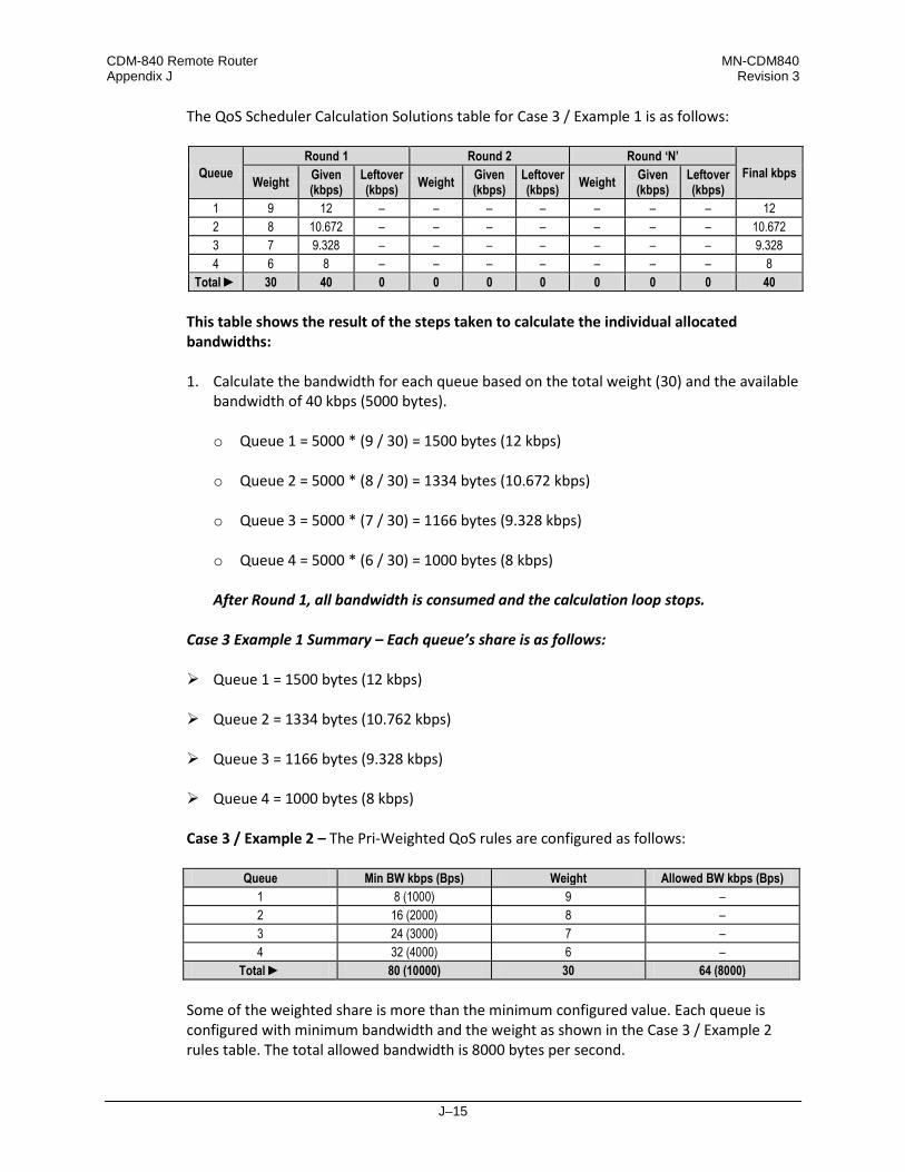
CDM-840 Remote Router MN-CDM840 Appendix J Revision 3
J–15
The QoS Scheduler Calculation Solutions table for Case 3 / Example 1 is as follows:
Queue Round 1 Round 2 Round ‘N’
Final kbps Weight Given (kbps)
Leftover (kbps) Weight Given
(kbps) Leftover (kbps) Weight Given
(kbps) Leftover (kbps)
1 9 12 – – – – – – – 12 2 8 10.672 – – – – – – – 10.672 3 7 9.328 – – – – – – – 9.328 4 6 8 – – – – – – – 8
Total 30 40 0 0 0 0 0 0 0 40 This table shows the result of the steps taken to calculate the individual allocated bandwidths: 1. Calculate the bandwidth for each queue based on the total weight (30) and the available
bandwidth of 40 kbps (5000 bytes). o Queue 1 = 5000 * (9 / 30) = 1500 bytes (12 kbps)
o Queue 2 = 5000 * (8 / 30) = 1334 bytes (10.672 kbps)
o Queue 3 = 5000 * (7 / 30) = 1166 bytes (9.328 kbps)
o Queue 4 = 5000 * (6 / 30) = 1000 bytes (8 kbps)
After Round 1, all bandwidth is consumed and the calculation loop stops.
Case 3 Example 1 Summary – Each queue’s share is as follows:
Queue 1 = 1500 bytes (12 kbps)
Queue 2 = 1334 bytes (10.762 kbps)
Queue 3 = 1166 bytes (9.328 kbps)
Queue 4 = 1000 bytes (8 kbps) Case 3 / Example 2 – The Pri-Weighted QoS rules are configured as follows:
Queue Min BW kbps (Bps) Weight Allowed BW kbps (Bps) 1 8 (1000) 9 – 2 16 (2000) 8 – 3 24 (3000) 7 – 4 32 (4000) 6 –
Total 80 (10000) 30 64 (8000) Some of the weighted share is more than the minimum configured value. Each queue is configured with minimum bandwidth and the weight as shown in the Case 3 / Example 2 rules table. The total allowed bandwidth is 8000 bytes per second.

CDM-840 Remote Router MN-CDM840 Appendix J Revision 3
J–16
The QoS Scheduler Calculation Solutions table for Case 3 / Example 2 is as follows:
Queue Round 1 Round 2 Round ‘N’
Final kbps Weight Given (kbps)
Leftover (kbps) Weight Given
(kbps) Leftover (kbps) Weight Given
(kbps) Leftover (kbps)
1 9 12 – – – – – – – 12 2 8 10.762 – – – – – – – 10.762 3 7 9.328 – – – – – – – 9.328 4 6 8 – – – – – – – 8
Total 30 40 0 0 0 0 0 0 0 40 This table shows the result of the steps taken to calculate the individual allocated bandwidths: 1. Calculate the bandwidth for each queue based on the total weight (30) and the available
bandwidth of 64 kbps (8000 bytes). o Queue 1 = 8000 * (9 / 30) = 2400 bytes (19.2 kbps)
o Queue 2 = 8000 * (8 / 30) = 2133 bytes (17.064 kbps)
o Queue 3 = 8000 * (7 / 30) = 1866 bytes (14.928 kbps)
o Queue 4 = 8000 * (6 / 30) = 1600 bytes (12.8 kbps)
2. After Round 1, only Queues 3 and 4 have yet to reach their minimum bandwidth.
Calculate the bandwidth for each queue based on the total weight (13) and the available bandwidth (1534 bytes): o Queue 3 = 1534 * (7 / 13) = 826 bytes (6.608 kbps)
o Queue 4 = 8000 * (6 / 30) = 708 bytes (5.664 kbps)
After Round 2, all bandwidth is consumed and the calculation loop stops.
Case 3 Example 2 Summary – Each queue’s share is as follows:
Queue 1 = 1000 bytes (8 kbps)
Queue 2 = 2000 bytes (16 kpbs)
Queue 3 = 2692 bytes (21.536 kbps)
Queue 4 = 2308 bytes (18.464 kbps)

CDM-840 Remote Router MN-CDM840 Appendix J Revision 3
J–17
J.2.2.4 QoS Group DiffServ Control Mode
QoS Group DiffServ is fully compliant to RFC standards. In DiffServ Control Mode, the system automatically configures the rules with DSCP code points, priority values, and WRED. You may only configure the service rate and drop precedence levels for Assured Forwarding (ASFD) classes. Use the CDM-840 HTTP Interface ‘Configuration | WAN | QoS’ page for complete management of the DiffServ features. Figure J-5 shows the page appearance with DiffServ as the selected QoS Control Mode.
Figure J-5. CDM-840 HTTP Interface – Configuration | WAN | QoS Page Example
(Control Mode = DiffServ)
J.2.2.4.1 DiffServ Operational Examples
Figure J-5 shows the DiffServ QoS Rule Table. During congestion, the QoS engine first services the prioritized Class Selector 1 through 7 queues (see the “Priority” and “Per-Hop Behavior (PHB)” columns); any remaining capacity is then "shared" among the Assured Forwarding Classes 1 through 4 (AF 1-4) and the Default class.

CDM-840 Remote Router MN-CDM840 Appendix J Revision 3
J–18
The Service Rate is the minimum rate, in kbps, that the QoS engine attempts to provide the AF class if the capacity exists during congestion. It is similar to a CIR but it is not absolute and it is NOT guaranteed over the Priority 1 through 7 classes. If there is no congestion, there is no maximum limit on the AF class. However, during congestion, an AF class with Service Rate of “0” may experience near 100% discard or very high levels of discard as compared with other AF Classes with greater Service Rates. The QoS engine will not attempt to maintain a minimum rate for that class; however, Assured Forwarding algorithms may not cut that class off completely. AF dropping is NOT controlled by data rate, but by the status of the system buffer. Any time there is "buffering" of the data, there is risk of AF traffic dropping. The maximum data rate without dropping is always the size of the capacity of the link (minus the demand of Classes 1 through 7). There is NO maximum data rate for the AF Class except for the total capacity rate, regardless of the configured "service rate" or buffer settings. These values are significant ONLY when there is enough WAN congestion to force the system to start buffering data. For example: If the Service Rate for Assured Forwarding Class 3 is 500 kbps, what is the maximum data rate permitted – without dropping – for Low, Medium and High Drop Precedence if the Service Rate we have is 100 kpbs, 90 kbps, or 80 kbps? First, consider this common configuration: • AF4 Service Rate 500 kbps Drop Precedence: Low=100% Med=75% High=50%
• AF3 Service Rate 500 kbps Drop Precedence: Low=100% Med=75% High=50%
• WAN Capacity = 7000 kbps
• AF4 traffic = 3000 kbps demanded 3000 kbps passed
• AF3 traffic = 3000 kbps demanded 3000 kbps passed
Here, because the total traffic is less than the WAN capacity, there is no dropping regardless of the Service Rate or Drop Precedence percentage. The low Service Rates have no impact at all on the data rate that is passed. Next, using the same configuration parameters, consider the following: • WAN Capacity = 7000 kbps
• Class 6 traffic = 5000 kbps demanded 5000 kbps passed
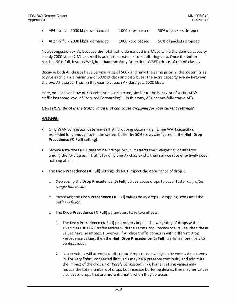
CDM-840 Remote Router MN-CDM840 Appendix J Revision 3
J–19
• AF4 traffic = 2000 kbps demanded 1000 kbps passed 50% of packets dropped
• AF3 traffic = 2000 kbps demanded 1000 kbps passed 50% of packets dropped Now, congestion exists because the total traffic demanded is 9 Mbps while the defined capacity is only 7000 kbps (7 Mbps). At this point, the system starts buffering data. Once the buffer reaches 50% full, it starts Weighted Random Early Detection (WRED) drops of the AF classes. Because both AF classes have Service rates of 500k and have the same priority, the system tries to give each class a minimum of 500k of data and distributes the extra capacity evenly between the two AF classes. Thus, in this example, each AF class gets 1000 kbps. Here, you can see how AF3 Service rate is respected, similar to the behavior of a CIR. AF3's traffic has some level of "Assured Forwarding" – in this way, AF4 cannot fully starve AF3. QUESTION: What is the traffic value that can cause dropping for your current settings? ANSWER: • Only WAN congestion determines IF AF dropping occurs – i.e., when WAN capacity is
exceeded long enough to fill the system buffer by 50% (or as configured in the High Drop Precedence (% Full) setting).
• Service Rate does NOT determine if drops occur. It affects the "weighting" of discards among the AF classes. If traffic for only one AF class exists, then service rate effectively does nothing at all.
• The Drop Precedence (% Full) settings do NOT impact the occurrence of drops:
o Decreasing the Drop Precedence (% Full) values cause drops to occur faster only after congestion occurs.
o Increasing the Drop Precedence (% Full) values delay drops – dropping waits until the buffer is fuller.
o The Drop Precedence (% Full) parameters have two effects:
1. The Drop Precedence (% Full) parameters impact the weighting of drops within a given class. If all AF traffic arrives with the same Drop Precedence values, then these values have no impact. However, if AF class traffic comes in with different Drop Precedence values, then the High Drop Precedence (% Full) traffic is more likely to be discarded.
2. Lower values will attempt to distribute drops more evenly as the excess data comes in. For very lightly congested links, this may help preserve continuity and minimize the impact of the drops. For barely congested links, higher setting values may reduce the total numbers of drops but increase buffering delays; these higher values also cause drops that are more dramatic when they do occur.

CDM-840 Remote Router MN-CDM840 Appendix J Revision 3
J–20
Which parameter effect is better for your particular traffic? Sudden severe drops are resultant with High Drop Precedence (% Full) values, while more gradual distributed drops result with Low Drop Precedence (% Full) values. Experience indicates that congestion rarely exists in just the right "sweet spot" for this to become a significant question. Under heavy congestion, the impact of changing these settings is minimal. Under severe/sustained congestion, you will get the large discards regardless. The Service Rates can help to "weight" the priority between AF classes under these congestion states.
J.3 QoS Congestion Avoidance
The QoS system supports Weighted Random Early Detection (WRED) based congestion avoidance. WRED can be enabled or disabled on any queue. When WRED is disabled, upon overdriving the queue the packets will be tail-dropped. For example, using the CDM-840 HTTP Interface ‘Configuration | WAN | QoS’ page: 1. Select the DiffServ QoS Group Control Mode.
2. Set the modem Tx bandwidth to 10000 kbps. 3. The data rate of the modem drops down from 10000 kbps to 8700 kbps due to Es/No and
ACM MODCOD adjustment. 4. The input data streams to the modem are the same as those used in the Min/Max QoS
example provided in Sect. J.2.2.2.
QUESTION: What is the total output data rate and what are the individual port output data rates? ANSWER: • The QoS system first drains Priority 1 traffic. Since the management data stream is only 200
kbps, after serving Priority 1 traffic, QoS still has 9800 kbps (10000 – 200 = 9800).
• QoS next drains Priority 2’s 800 kbps traffic. After the end of the Priority 2 traffic, QoS still has 9000 kbps traffic available (9800 – 800 = 9000).
• Similarly, QoS walks through all priorities until it hits the ASFD classes:
o The beginning of ASFD Classes QoS leftover bandwidth is 2000 kbps.
o All ASFD classes have the same Priority of 7, with different service rates.
o ASFD service rate is a Committed Information Rate (CIR), except serviced if bandwidth available after serving all high priority queues. In this case, 2000 kbps bandwidth is

CDM-840 Remote Router MN-CDM840 Appendix J Revision 3
J–21
available, serving all service rates first. The total of all ASFD service rates are 1600 kbps, which is less than the 2 Mbps leftover bandwidth.
o After serving the service rates, the leftover bandwidth is 400 kbps. This 400 kbps will be
distributed to all ASFD classes equally in Round-robin fashion until either there is no more bandwidth, or the input streams have no data.
o The resulting individual data rates are as follows:
Stream Priority PHB / DSCP Code Service Rate Drop Precedence Data Rate
Management 1 CS7 / b111000 200 kbps 9800 kbps 200 kbps Networking
Control 2 CS6 / b110000 800 kbps 9000 kbps 800 kbps
Voice 3 EXFD / b101110 1000 kbps 8000 kbps 1000 kbps
Video 3 CS5 / b101000 4000 kbps 4000 kbps 4000 kbps
Data-1 4 CS4 / b100000 550 kbps 3450 kbps 550 kbps
Data-2 5 CS3 / b011000 1450 kbps 2000 kbps 1450 kbps
Data-3 7 ASFD4 / b100010 1000 kbps N/A 100 + 100 kbps
Data-4 7 ASFD3 / b011010 1000 kbps N/A 400 + 100 kbps
Data-5 7 ASFD2 / b010010 1000 kbps N/A 500 + 100 kbps
Data-6 7 ASFD1 / b001010 1000 kbps N/A 800 + 100 kbps
Data-7 8 BE / bXXXXXX 2000 kbps N/A 0 kbps
Total 14000 kbps 0 kbps 10000 kbps
CDM-840 Remote Router MN-CDM840 Appendix J Revision 3
J–22
J.4 QoS with ACM/VCM (Adaptive/Variable Coding and Modulation)
When ACM is enabled, the modem is configured with symbol rate, while QoS operates on data rate. Although the symbol rate will be constant in ACM/VCM mode, the data rate will not be constant. As a result, the modem’s data rate can vary "on-the-fly” based on the Es/No. The data rate can be more or less than when QoS was first configured, or when the modems first boots.
J.4.1 Maximum Clipping
Due to ACM, when in QoS Max/Pri mode and the data rate’s available bandwidth exceeds the maximum clipping rate, the QoS system limits the output rate of that rule to configured maximum clipping rate. When the available data rate is less than the maximum clipping rate, the QoS system has nothing to clip, since it has not exceeded the defined maximum bandwidth rate.
J.4.2 Minimum Data Rate
Due to ACM, when the data rate’s available bandwidth exceeds the minimum data rate (per QoS Min/Max and DiffServ modes’ ASFD classes), the QoS system operates as normal; since the minimum has been met, the available bandwidth is shared among all other same priorities in Round-robin fashion. When the available data rate is less than the minimum data rate, then the QoS system shares equally among all same priority queues in a Round-robin fashion until either minimum bandwidth is met, or no more data is available to drain. For example, using the CDM-840 HTTP Interface ‘Configuration | WAN | QoS’ page: 1. Select the DiffServ QoS Group Control Mode.
2. Enable ACM. 3. The data rate of the modem drops down from 10000 kbps to 8700 kbps due to Es/No. 4. Input data streams are the same as with the QoS Group Min/Max Mode example (see Sect.
J.2.2.2). QUESTION: What will be the total data rate and what will be the individual data rates? ANSWER: • After serving all high priority queues, only 500 kbps is left for ASFD classes.
• This leftover bandwidth is less than the total minimum bandwidth; it must therefore share
the residual 500 kbps among all four ASFD classes equally – i.e., 500 / 4 = 175 kbps per class.

CDM-840 Remote Router MN-CDM840 Appendix J Revision 3
J–23
• Since ASFD 4 has the service rate 100 kbps, the excess 75 kbps will be given the other queues where the service rate not met.
• In this case, the 75 kbps again will share equally among ASFD3, ASFD2, and ASFD1 since
these service rates were not met. • The resulting individual data rate is as follows:
Stream Priority PHB / DSCP Code Input Data Date (kbps)
Leftover BW After Serving the Queue
(kbps) QoS Output Data
Rate (kbps)
Management 1 CS7 / b111000 200 9800 200 Networking
Control 2 CS6 / b110000 800 9000 800
Voice 3 EXFD / b101110 1000 8000 1000 Video 3 CS5 / b101000 4000 4000 4000 Data-1 4 CS4 / b100000 550 3450 550 Data-2 5 CS3 / b011000 1450 2000 1450 Data-3 7 ASFD4 / b100010 1000 N/A 100 Data-4 7 ASFD3 / b011010 1000 N/A 175 + 25 Data-5 7 ASFD2 / b010010 1000 N/A 175 + 25 Data-6 7 ASFD1 / b001010 1000 N/A 175 + 25 Data-7 8 BE / bXXXXXX 2000 N/A 0
Total 14000 0 8700

CDM-840 Remote Router MN-CDM840 Appendix J Revision 3
J–24
J.4.3 Highly Degraded Remote
In the ACM/VCM Outbound channel, when a remote either highly degrades or loses communication, prior to FW Ver. 1.6.2.X the ACM/VCM controller in the CTOG-250 would assign a low MODCOD for traffic destined to a given remote, and attempt to honor any configured CIR. As a result, the number of symbols used to meet CIR for that degraded remote was disproportionate and resulted in a network-wide reduction in throughput. The Highly Degraded Remote feature allows you to specify a “CIR Threshold MODCOD” on each CDM-840 that is automatically communicated to the CTOG-250. If the remote fades below this MODCOD and the Outbound link is fully utilized, the CTOG-250 will no longer try to maintain the CIR for traffic destined to that remote. Rather, the ACM/VCM QoS system will attempt to maintain a “fair share” of symbols for a highly degraded remote based upon the nominal number of symbols assigned to each QoS Group and its configured CIR. The data rate at which a remote is clamped will scale as the remote degrades below the “CIR Threshold MODCOD” – i.e., the more it fades, the more the data rate is clamped. As shown in Figure J-6: Use the CDM-840 HTTP Interface ‘Configuration | WAN | Demod | ACM’ page to configure the “CIR Threshold MODCOD.” You can use the CTOG-250 HTTP Interface ‘Configuration | WAN | Remotes Sites | Configuration’ page to view the currently configured value.
Figure J-6. Highly Degraded Remote Function – CDM-840 and CTOG-250 HTTP Interfaces

CDM-840 Remote Router MN-CDM840 Appendix J Revision 3
J–25
J.5 QoS Statistics Reporting
The system collects extensive statistics that you can use to monitor performance in real time, or store for historical analysis. Use the CDM-840 HTTP Interface ‘Status | Statistics | QoS’ page (Figure J-7) to view this information.
(TOP) Page with QoS Control Mode = OFF, Max/Pri, Min/Max, or Pri-Weighted (BOTTOM) QoS Statistics Section with QoS Control Mode = DiffServ
Figure J-7. CDM-840 HTTP Interface – Status | Statistics | QoS Page Examples

CDM-840 Remote Router MN-CDM840 Appendix J Revision 3
J–26
This page, depending on the active Control Mode, displays the following information:
• Entire Return Statistics (updated every second with live data):
o Current Throughput (kbps) o Unused Capacity (kbps) o Total Capacity (kbps) o Symbols per second Utilization (%) o Average bits/symbols per second
• QoS Group Statistics (updated every second):
o Totals for all QoS Groups sharing the return
o Current aggregate data rate for each QoS Group
o CIR Availability (%): Last 1 minute, 15 minutes, 60 minutes % of time for the last 1 minute, 15 minutes, 60 minutes that CIR was available
when requested.
• Per Rule Statistic s (updated every second): o Rule Name o Tx Packet Rate (packets/second)
o Tx Packets per Rule o Tx Data Rate (kbps)
o Dropped Packets per Rule o Totals for all Rules per Group

K–1
Appendix K. RAN/WAN OPTIMIZATION
K.1 Overview
The CDM-840 Remote Router supports E1 RAN (Radio Access Network) Optimization as a FAST option. This appendix provides detailed information about Comtech EF Data’s patent pending RAN Optimization technology, which is designed to provide maximum savings while maintaining superior voice quality.
K.1.1 Radio Access Network (RAN)
Figure K-1 illustrates typical 2G and 3G Radio Access Networks.
Figure K-1. 2G / 3G Radio Access Network (RAN)
In the cellular network, the RAN connects cell-site nodes with central-site nodes:

CDM-840 Remote Router MN-CDM840 Appendix K Revision 3
K–2
• For Global System for Mobile Communications (GSM) / 2G, the Base Transceiver Stations (BTS) connect to the Base Station Controllers (BSC) via the Abis interface. Voice, data and signaling are transported over one or more E1s.
• For Universal Mobile Telecommunications Systems (UMTS) / 3G, the NodeB connects to the Radio Network Controller (RNC) via the “lub” interface. Voice, data and signaling are transported over one or more E1s using Asynchronous Transfer Mode (ATM).
K.1.2 RAN Inefficiency
The 2G/3G RAN design is not efficient for satellite backhaul. For example, in the GSM Abis interface shown in Figure K-2, the resource allocation is on a fixed basis (one or more E1s per BTS), irrespective of the actual traffic. Within the E1, the Time Slots (TS) are dedicated to signaling, voice and data per Transceiver (TRX).
Figure K-2. Typical Abis Map

CDM-840 Remote Router MN-CDM840 Appendix K Revision 3
K–3
K.2 E1 RAN Optimization
Jointly developed by Comtech EF Data, Comtech AHA Enterprise Products Group, and CEFD subsidiary Memotec Inc., RAN Optimization technology significantly reduces the Wide Area Network (WAN) / satellite bandwidth required to carry an E1 bearer used for cellular backhaul. RAN Optimization allows the transmit modem data rate to be reduced relative to the input terrestrial data rate, thus allowing the transport of a user-selectable channel subset of bearer E1 using less bandwidth. In the receive direction, the data is restored to the E1 format for transport over the G.703 E1 interface. The process is designed to allow varying levels of optimization to accommodate the incoming terrestrial data in the reduced modem data rate. Optimization performance depends on the traffic profile and the difference between the terrestrial data rate (based on input timeslot selection) and the transmit modem data rate. The optimization is performed in hardware for optimal performance. The user has complete control over the desired level of optimization by selecting the time slots to be optimized, and the transmit modem data rate. Depending on the traffic profile, typical bandwidth reduction of 30-35% can be achieved with little or no impact to the voice quality. Users have the option to reduce WAN bandwidth by as much as 60% relative to the ingress data rate – this allows the users to achieve desired bandwidth savings while maintaining desired voice quality.
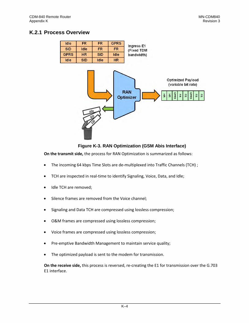
CDM-840 Remote Router MN-CDM840 Appendix K Revision 3
K–4
K.2.1 Process Overview
Figure K-3. RAN Optimization (GSM Abis Interface)
On the transmit side, the process for RAN Optimization is summarized as follows: • The incoming 64 kbps Time Slots are de-multiplexed into Traffic Channels (TCH) ;
• TCH are inspected in real-time to identify Signaling, Voice, Data, and Idle;
• Idle TCH are removed;
• Silence frames are removed from the Voice channel;
• Signaling and Data TCH are compressed using lossless compression;
• O&M frames are compressed using lossless compression;
• Voice frames are compressed using lossless compression;
• Pre-emptive Bandwidth Management to maintain service quality;
• The optimized payload is sent to the modem for transmission. On the receive side, this process is reversed, re-creating the E1 for transmission over the G.703 E1 interface.

CDM-840 Remote Router MN-CDM840 Appendix K Revision 3
K–5
K.2.2 WAN Link Dimensioning and Pre-emptive Bandwidth Management
RAN traffic varies over time – variations during the day that peak at certain time(s), and longer term variation as user density/profile(s) changes. The WAN link can be dimensioned to accommodate the peak traffic, or it can be dimensioned to meet a statistically derived value (e.g. average traffic). Dimensioning the WAN link for peak traffic may not be economically viable. However, dimensioning the WAN link for average traffic has its challenges. Specifically: What happens when the optimized traffic exceeds WAN capacity? Typical of most other vendors’ RAN optimization solutions, Figure K-4 shows the optimized Abis traffic as a function of time, depending on the BTS traffic load. The red line is the pre-defined WAN link capacity (assuming 35% target optimization). Each time the optimized Abis traffic exceeds WAN capacity, packets are dropped and the voice quality degrades dramatically – even leading to dropped calls or in the worst case, causing BTS drop.
Figure K-4. Optimized Abis Traffic without Pre-emptive BW Management
The simplistic packet drop employed by most vendors in case of WAN congestion has potentially disastrous effects on voice quality and call handling – the results can include clicks, blank calls, and eventually call drops, especially if the BCCH channel of the TRX is impacted. In the worst case, it may even lead to BTS drop. To compensate, most other vendor solutions are forced to over-dimension the WAN link, which leads to significant inefficiencies. This methodology should not be acceptable to mobile operators. A good RAN optimization solution should be nearly transparent, and should provide the same level of service to the mobile customers as when there is no RAN Optimization while providing a significant reduction in RAN transmission bandwidth. As implemented by Comtech EF Data, the superior method of handling WAN congestion is to perform pre-emptive and selective voice packet discard. Comtech EF Data’s RAN Optimization

CDM-840 Remote Router MN-CDM840 Appendix K Revision 3
K–6
solution employs a sophisticated bandwidth management capability to maintain Service Quality. The signaling and O&M traffic is always protected from being dropped in case of WAN congestion – this ensures that the BTS/NodeB stays connected and synchronized. The bandwidth manager smoothes peak traffic variation before the optimized RAN traffic reaches the available WAN capacity – this mechanism maintains good voice quality while effectively reaching the optimal target optimization rate. Comtech EF Data’s patent pending algorithm on voice packet discard is designed to minimize the impact on the voice quality. This results in superior voice quality and improved Service Quality even at peak hour traffic load. Implementing a RAN optimization solution without such capability serves little purpose.
Figure K-5. Optimized Abis Traffic with Pre-emptive BW Management

CDM-840 Remote Router MN-CDM840 Appendix K Revision 3
K–7
K.2.2.1 Performance Monitoring via the CDM-840 HTTP Interface
Chapter 6. ETHERNET-BASED REMOTE PRODUCT MANAGEMENT
YOU MAY PROCEED WITH ETHERNET-BASED REMOTE PRODUCT MANAGEMENT, ASSUMING THAT: • YOUR CDM-840 IS OPERATING WITH THE LATEST VERSION FIRMWARE FILES.
• YOUR CDM-840 IS CONNECTED TO A USER-SUPPLIED, WINDOWS-BASED PC AS
FOLLOWS:
O THE PC SERIAL PORT IS CONNECTED TO THE CDM-840 REAR PANEL ‘CONSOLE’ PORT WITH A USER-SUPPLIED SERIAL CABLE.
o THE PC ETHERNET PORT IS CONNECTED TO THE CDM-840 REAR PANEL ‘ETHERNET | MANAGEMENT | FE’ ETHERNET PORT WITH A USER-SUPPLIED HUB, SWITCH, OR DIRECT ETHERNET CABLE CONNECTION.
O THE PC IS RUNNING A TERMINAL EMULATION PROGRAM (FOR OPERATION OF THE CDM-840 SERIAL INTERFACE) AND A COMPATIBLE WEB BROWSER (FOR OPERATION OF THE HTTP INTERFACE).
• YOU HAVE NOTED THE CDM-840 MANAGEMENT IP ADDRESS USING THE
CDM-840 SERIAL INTERFACE.
• YOU HAVE PRUCHASED AND ACTIVATED THE E1 RAN OPTIMIZATION FAST FEATURE.
The RAN Optimizer collects detailed usage and performance statistics that are accessible from the CDM-840 HTTP Interface. Error! Reference source not found. shows the CDM-840 HTTP Interface “splash” page, and the menu tree for accessing this monitoring feature. Page functionality that is not specific to this operation appears dimmed.

CDM-840 Remote Router MN-CDM840 Appendix K Revision 3
K–8
Figure K-6. CDM-840 HTTP Interface and Menu Tree – Link Performance Monitoring
(FW Ver. 1.6.2.X) Click the Status, Statistics, and Trending tabs to open the Trending (performance monitoring) page (Error! Reference source not found.). The graphs are viewable by selectable time spans. They display information needed to monitor the link performance and to take appropriate action as needed.

CDM-840 Remote Router MN-CDM840 Appendix K Revision 3
K–9
To initialize the page: Select the Time Span for the graphs as 20 minutes, 3 Days, or 30 Days. Then, select Auto Update if you wish to set the trending data refresh interval from the default of 10 minutes to 5 seconds. Click [Update] to execute your selection. Allow a few seconds for the graphs to visually update.
Figure K-7. CDM-840 HTTP Interface – Status | Statistics | Trending Page
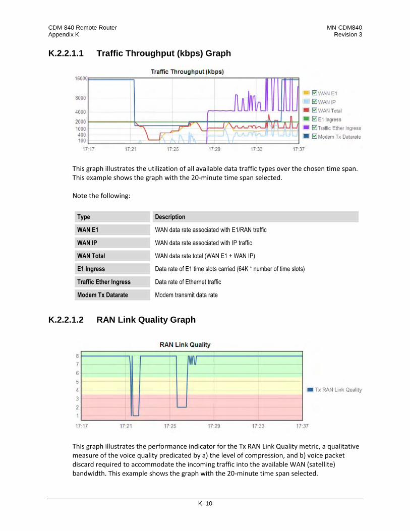
CDM-840 Remote Router MN-CDM840 Appendix K Revision 3
K–10
K.2.2.1.1 Traffic Throughput (kbps) Graph
This graph illustrates the utilization of all available data traffic types over the chosen time span. This example shows the graph with the 20-minute time span selected. Note the following:
Type Description
WAN E1 WAN data rate associated with E1/RAN traffic
WAN IP WAN data rate associated with IP traffic
WAN Total WAN data rate total (WAN E1 + WAN IP)
E1 Ingress Data rate of E1 time slots carried (64K * number of time slots)
Traffic Ether Ingress Data rate of Ethernet traffic
Modem Tx Datarate Modem transmit data rate
K.2.2.1.2 RAN Link Quality Graph
This graph illustrates the performance indicator for the Tx RAN Link Quality metric, a qualitative measure of the voice quality predicated by a) the level of compression, and b) voice packet discard required to accommodate the incoming traffic into the available WAN (satellite) bandwidth. This example shows the graph with the 20-minute time span selected.

CDM-840 Remote Router MN-CDM840 Appendix K Revision 3
K–11
Association of the Link Quality Metric to its comparative Link Quality is as follows:
Link Quality Metric Link Quality 8 Excellent 7 Very Good 6 Good 5 Fair 4 Average 3 Poor 2
Very Poor 1
Note that ‘8’ on the graph indicates the highest quality, with no voice traffic discard.
K.2.2.1.3 RANOp Savings Graph
This graph illustrates the performance indicator for Tx RAN Optimization on an actual “percentage of savings” basis over the chosen time span. This example shows the graph with the 20-minute time span selected.

CDM-840 Remote Router MN-CDM840 Appendix K Revision 3
K–12
Notes:
L–1
Appendix L. dMESH (VMS DYNAMIC MESH) SOLUTIONS
L.1 Overview
VMS v3.x.x VIPERSAT Management System User Guide (CEFD P/N MN/22156)
dMesh (Dynamic Mesh) connectivity minimizes the requirement for communications that are routed through a hub and re-routed back to the remote segments of an Advanced VSAT Network. The benefit of a dMesh circuit is that it reduces the time it takes to establish and maintain communications between remote sites. This eliminates double hop scenarios, provides less latency, and improves Quality of Service (QoS) between remote AVSAT locations; geostationary satellite single hop link latency is thereby maintained for real-time applications such as VoIP and videoconferencing. This is not a new concept – it has been implemented for many years in terrestrial microwave applications. Although there are many satellite modem manufacturers producing new generations of products, few provide the means to address point-to-point or point-to-multipoint mesh connectivity or offer premium commercial-grade services between AVSAT locations. Mesh offerings are typically limited to TDM/TDMA and DAMA solutions, or “best-effort” service for circuit-switched voice as well as limited VoIP and data throughput. Comtech EF Data leverages the concept of Bandwidth-on-Demand (BoD) by taking advantage of Dynamic Single Channel per Carrier (dSCPC) in a mesh environment and adapting it to Comtech EF Data’s Advanced VSAT Network platform. This adds dynamic point-to-multipoint SCPC mesh circuits to the network’s existing hub and remote link, and DVB-S2 outbound and VersaFEC dSCPC to the return link. Comtech EF Data manages these elements, and provides BoD in a mesh environment through its Vipersat Management System (VMS), the software switching engine behind our Vipersat technology.

CDM-840 Remote Router MN-CDM840 Appendix L Revision 3
L–2
L.2 Operational Features
L.2.1 VMS (Vipersat Management System)
Figure L-1. VMS Graphical User Interface (GUI)
Figure L-1 shows a typical VMS graphical user interface (GUI). The VMS GUI displays a graphical representation of the deployed modems and demodulators, remote subnets, RF carriers, and switching events. Figure L-2 shows typical deployment of a Comtech EF Data Advanced VSAT Network. The Advanced VSAT IP Network operates at Layer 3 in a routed mode of operation that supports dynamic mesh. A major advantage of the Vipersat technology is that its design encompasses the use of Comtech EF Data’s Advanced VSAT offerings (CTOG-250 Comtech Traffic Optimization Gateway w/CDM-800 Gateway Router and CDD-880 Multi Receiver Router at the hub site, and CDM-840 Remote Routers with CDD-880 Multi Receiver Routers at the remote sites). For example, the Vipersat technology accommodates a mesh environment as follows: • Similarly-equipped CDD-880s are used at the Vipersat-enabled hub and at the remote sites.
The only differences between the network hub and remote site CDD-880s are the software interfaces and VMS configuration of the units. This intuitive design and configuration allows

CDM-840 Remote Router MN-CDM840 Appendix L Revision 3
L–3
for rapid deployment of units at the remote site and their addition to the VMS database at the hub site.
• The network provides a true single hop solution for point-to-point or point-to-multipoint connectivity between remote sites. VMS automatically sets up the circuits either by Type of Service (ToS) detection through the remote site CDM-840, or a Distribution List configured in the VMS server with the respective remote site policies.
Figure L-2. VMS-configured Advanced VSAT Network
Startup of an application such as VoIP or videoconferencing initiates a switch request using ToS Detection. Upon ToS protocol detection, the CDM-840 forwards a switch request defined by network operator switching policy to VMS for the required bandwidth. VMS in turn, upon verification of available space segment and CDD-880 Expansion Demodulators, sends switching commands to the appropriate remote CDM-840 subnets, thus changing the CDM-840’s Tx frequency/power level/data rate and ModCod, where applicable. An available remote site CDD-880 is also tuned to receive the corresponding remote transmission, and a mesh circuit is created. As with Remote Sites ‘A’ and ‘B’, Remote Site ‘N’ is communicating with the Hub site via the CDD-880 Expansion Unit on another internal demodulator port. Since the CDD-880 Expansion Units at Remote Sites ‘A’ and ‘B’ also have a demodulator port tuned to their respective carrier, it is necessary to filter the traffic between them at the Hub site to avoid duplicate packets and unnecessary hub loading. This requires the entry of filter routes only at the hub’s CDD-880 Expansion Unit. VMS automatically manages these routes – entering them when needed, and removing them when not. From the VMS server interface, the Distribution List feature allows the operator to pre-define mesh circuits based on an Entry Channel Mode (ECM) switch, multicast transmission from remotes to a group of remotes, or the setup of monitor remotes. When the remote terminals

CDM-840 Remote Router MN-CDM840 Appendix L Revision 3
L–4
are powered on, their presence in the dSCPC distribution mesh is constant unless taken out by operator intervention.
L.2.2 Return Link VersaFEC® ACM (Adaptive Coding and Modulation)
L.2.2.1 VersaFEC®
The transmit (Tx) side of the CDM-840 uses a family of short-block LDPC codes called VersaFEC®. VersaFEC is a patent pending technology wholly owned and developed by Comtech EF Data and Comtech AHA Enterprise Products Group (the VersaFEC name is a trademark registered to Comtech AHA). VersaFEC is ideal for lower data rates that demand the shortest possible latency. The VersaFEC codes are equally well-suited to Constant Coding and Modulation (CCM) applications.
L.2.2.2 ACM (Adaptive Coding and Modulation)
ACM (Adaptive Coding and Modulation) in the CDM-840 is used in conjunction with VersaFEC and is currently for IP traffic only. ACM is a technique that allows for automatic change in modulation and FEC Code Rate in response to changing link conditions. ACM may be used in packet-based satellite links to boost system throughput. The basic goal of ACM is to capture historically unused satellite system link margin and convert this margin into additional data throughput. An ACM system is set up using a constant physical layer symbol rate – and therefore occupied bandwidth – and power, but with a varying assortment of modulation and coding combinations called ModCods. The ModCods are selected to span a range of Es/No (Energy per Symbol to Noise density ratio) so that if a system detects a change in link margin – e.g., fading – it can use a different ModCod to preserve the link, albeit at a different user throughput rate. Therefore, in an ACM system, as Es/No increases or decreases, so does the user data rate. With ACM enabled, the CDM-840 offers significant operational enhancements: • ACM maximizes throughput regardless of link conditions (noise, clear sky, rain fade, inclined
orbit, antenna pointing error, or other impairments). Initial setup is easy and requires no further user intervention.
• ACM turns fade margin into increased link capacity – gains of 100% or more are possible, compared to traditional CCM. This is accomplished by automatically adapting the modulation type and FEC code rate to give highest possible throughput. With a CCM system, severe rain fading can cause the total loss of the link – the result being zero throughput. ACM can keep the link active during heavy fades with lower throughput, and can yield much higher system availability.
CDM-840 Remote Router MN-CDM840 Appendix L Revision 3
L–5
The requirements for an ACM system that approaches the minimum possible latency are:
• The shortest possible LDPC codes that give performance at or very close to DVB-S2, in order to minimize latency, and which do not use interleaving.
• Design of the encoder to further reduce latency to the minimum possible.
• A constant number of symbols per block, to reduce the demodulator and decoder complexity, and significantly also reduces latency in the ACM case.
• The elimination of the need for pilot symbols for carrier tracking at low SNR by substitution of other modulation techniques. This further reduces the complexity of the demodulator.
• A reduction in the number of ModCods to further reduce complexity.
• The inclusion, at the physical layer, of an overhead channel to permit the reporting of SNR metrics back to the originating end. Note that this does not have to be enabled or disabled – it is part of the fundamental frame structure of VersaFEC ACM, and has been take into account in the code rate.
L.2.2.2.1 ACM and dMesh
Although ACM and dMesh are independent of one another, ACM is supported in a dMesh environment. Return link ACM for the remote CDM-840 to the hub CDD-880 link is modeled after the Comtech EF Data CDM-625 Advanced Satellite Modem’s ACM approach and framing, while adapting control techniques to operate in a dynamic point-to-multipoint network that includes a mesh environment.
L.2.2.2.2 ACM and DPC (Dynamic Power Control)
Appendix M. DPC (VMS DYNAMIC POWER CONTROL)
The DPC (Dynamic Power Control) feature provided in Comtech EF Data’s Advanced VSAT products provides a mechanism whereby remote satellite uplinks have their transmit power levels adjusted in order to optimize the receive signal quality as measured by the corresponding demodulator ES/N0 (the ratio of energy per symbol to noise density). DPC and ACM function independent of one another, whereby power is modified first or second in combination with ACM. Depending on conditions, DPC and ACM can be operated exclusively or in combination, sharing the same resources for checks and balances. When DPC and ACM are operating in combination, the CDM-840/CDM-850 receives the LQRM comparing value to current settings and depending on conditions adjusts power or modifies ModCod.

CDM-840 Remote Router MN-CDM840 Appendix L Revision 3
L–6
L.3 Operational Example
L.3.1 Requirements for Bandwidth-on-Demand and dMesh with SHOD (Single Hop on Demand)
For any dynamic switch to occur, you need to adhere to some minimum requirements: • Your active network is an Advanced VSAT Network platform Version 1.5.2.1 or greater
running a Vipersat Management System (e.g., VMS Version 3.12.x).
• Space segment in the shared dSCPC bandwidth pool must be available.
• CDD-880 Expansion Units must be available at the hub site and each AVSAT remote site. o The hub site and remote site must be equipped identically. You may populate each
CDD-880 1RU chassis with up to 12 demodulators – two demodulators per card, up to six cards per unit. This provides a maximum of 12 point-to-multipoint dynamic mesh circuits between remote sites (assuming each remote site is equipped with a fully populated CDD-880).
o If more circuits are needed, you simply add more CDD-880s at the AVSAT remote sites
and at the hub location. (Again, the units at either side of the network must be populated equally with the appropriate number of demodulator cards.)
Such configurations allow transmission of a single carrier from an originating remote CDM-840, a benefit that results in requiring operation of a lower-wattage BUC and/or use of a smaller antenna, when compared with what would be required with multiple carriers transmitted from a remote site.
Care should be taken to insure that differential in receive gain between the hub antenna and remote mesh antennas does not exceed TBD.
L.3.2 dMesh Operation
Meshed links can be set up based on specific applications that are sent from one remote site to another remote site or group of remotes sites. The easiest way to demonstrate the meshing capability of a Vipersat-managed Advanced VSAT Network is by using Distribution Lists. Distribution Lists allow you to set up a list of sites to be included in a switch under defined circumstances, such as meshing based on an ECM switch, multicast transmission from a remote to a group of remotes, or the setup of monitor remotes. This feature can be used to tune expansion demodulators at a list of sites for upstream switched services, to provide for point-to-multipoint distribution on an InBand service connection.

CDM-840 Remote Router MN-CDM840 Appendix L Revision 3
L–7
L.3.2.1 Create a Distribution List
Chapter 3. VMS Configuration “Define Distribution Lists” in VMS v3.x.x VIPERSAT Management System User Guide (CEFD P/N MN/22156)
Use the VMS to set up a Distribution List. Do these steps: 1. From the VMS GUI, right click on a remote site icon to open the Properties page:
a) Highlight the Distribution Lists tag.
b) Right-click in the white space below the InBand Distribution Lists label. Click the [Insert] button that appears. The Distribute List dialogue window appears.
2. If the distribution is intended for multiple remotes, you may use the Distribute List dialogue
window to enter them:

CDM-840 Remote Router MN-CDM840 Appendix L Revision 3
L–8
a) The target box shows all zeros, which means that any packet destined to the subnets shown here causes the VMS to set up a mesh connection.
b) Enter a Label that is easy to remember, such as the name of the target remote (e.g., Remote 2).
c) Enter the network Address for the remote subnet.
d) Enter the subnet Mask.
e) Click [Add]. The network Address and subnet Mask appear in the Destinations window.
3. Add CDD-880 Expansion Units to Antenna View. To set up a mesh, the VMS must have
available CDD-880 Expansion Units at the target remote site. Remote site mesh units must be dropped on the antenna and made available as shown here:
Note that this is the antenna view for R2 (Remote 2) and Demodulator #1 of this remote site’s CDD-880 Expansion Unit is already involved in a mesh with R1 (Remote 1).
4. Define your filtering rules. The VMS dynamically enters filters at the Hub demodulator(s)
when it sets up a mesh. It does this to prevent loops and duplicate packets on the network. Filters are also a function of the mesh location at the remote site. The CDD-880 HTTP Interface Configuration | Network | Routing page (Figure L-3) defaults the Mesh Location to Hub.
To ensure proper operation and to prevent network loops, you MUST make sure that each remote site CDD-880 Expansion Unit has its Mesh Location set to Remote. The inset in Figure L-3 shows such a Mesh Location setting.
In CDD-880 Multi Receiver Router Installation Operation Manual (CEFD P/N MN-CDD880): See Sect. 6.3.3.3.1 Configuration | Network | Routing in Chapter 6. ETHERNET-BASED REMOTE PRODUCT MANAGEMENT for details about using this interface.

CDM-840 Remote Router MN-CDM840 Appendix L Revision 3
L–9
Figure L-3. CDD-880 HTTP Interface – Configuration | Network | Routing Page For each individual mesh connection, the VMS enters a SHOD (Single Hop On Demand) at the Hub site CDD-880 demodulator as shown in Figure L-3. The Filter Table lists the Destination Network IP/Mask and a Filter Map. This Filter Map corresponds to the Hub site CDD-880 demodulator that is tuned to the remote site originating the mesh.
The intent of this filter rule is to block any packets originating from R1 that are destined to R2. This prevents traffic to the meshed remote site from going on to the Hub LAN and being retransmitted by the TDM (CTOG-250) outbound.
5. Single Hop On Demand (SHOD): The VMS adds an additional SHOD filter to the Hub
CDD-880 for this subnet. If the traffic subnet is part of a subnet that can be described in one route statement (e.g., a subset of the same Class C that is the management subnet), this is
CDM-840 Remote Router MN-CDM840 Appendix L Revision 3
L–10
not necessary. However, any subnets that are past a router at the target remote must be entered as external subnets.
6. Mesh Setup Based on ToS Detection: The detection by a CDM-840 Remote Router of a ToS
stamped packet can provide the means for setting up a SHOD mesh connection from that remote to another remote within the network.
For these SHOD connections, it is assumed that each remote site that is part of the SHOD connection has, at minimum, one CDD-880 Expansion Unit.
When a Remote site CDM-840 detects a packet that has been stamped with a ToS value that matches the user defined value, the CDM-840 then sends a switch request to the VMS, requesting the user defined bandwidth. The switch request also contains the address that the ToS stamped packet was destined for. The VMS processes the switch request and compares the destination address to the list of known subnets to determine if the destination belongs to another remote within the network. If the address does belong to another remote, the VMS will look for available hardware and bandwidth, and then issue tuning commands to set up the connection. Each direction of the mesh is set up independently; i.e., the detection that occurs at Remote 1 establishes a connection from Remote 1 to the other remote involved. However, the other remote must perform detection for set up in the opposite direction, thus creating a full duplex mesh connection.

CDM-840 Remote Router MN-CDM840 Appendix L Revision 3
L–11
L.4 Compatibility
All Comtech EF Data products are designed to ensure seamless cohesion when interfacing its CDM-840s or demodulators to a single VMS Server. Table L-1 lists the available Comtech EF Data products that are supported by Vipersat technology.
Table L-1. Comtech EF Data Product Compatibility Reference
Product Max Data
Rate (Mbps)
In-Band
Out-of-
Band Mesh
dSCPC Switching Methods
Sche
duled
Manu
al
ToS
Load
QoS
VESP
Hitle
ss
Adva
nced
CDM-570/CDM-570L 9.98 X X X X X X X X X X X CDM-600/CDM-600L 20 X X X X X
CDM-625 25 X X X X X CDM-750 169 X X X X X
CDM-800 (p/o CTOG-250) X X X X X X X X X X X CDM-840/ODM-840 15.35 X X X X X X X X X X X
SLM-5650A 155 X X X X X X X X X CDD-562L 9.98 X X X X X X X X X X X
CDD-564/CDD-564L 9.98 X X X X X X X X X X X CDD-880 15.35 X X X X X X X X X X X
L.5 Summary
Vipersat provides a dynamic mesh for remote-to-remote communication through its use of a unique equipment topology and switching engine. It requires only a single transmitted SCPC carrier from each remote, as opposed to having multiple carriers at each site. Corresponding remote sites need available CDD-880 Multi-Receiver Router Expansion Units to receive the mesh transmission; this establishes a true dynamic SCPC circuit between remotes. Hardware costs are also significantly lower due to the ability to deploy the CDD-880s at both the hub location and the remote sites. ACM maintains link connectivity by “down revving” the ModCods while maintaining a constant symbol rate and power level.

CDM-840 Remote Router MN-CDM840 Appendix L Revision 3
L–12
Notes:

M–1
Appendix M. DPC (VMS DYNAMIC POWER CONTROL)
M.1 Overview
VMS v3.x.x VIPERSAT Management System User Guide (CEFD P/N MN/22156)
This appendix provides information on Dynamic Power Control in reference to the return path only – CDM-840 Remote Router to CDD-880 Multi Receiver Router control.
The DPC (Dynamic Power Control) feature provided in Comtech EF Data’s Advanced VSAT products provides a mechanism whereby remote satellite uplinks have their transmit power levels adjusted in order to optimize the receive signal quality as measured by the corresponding demodulator ES/N0 (the ratio of energy per symbol to noise density). This optimization process acts to either increase or decrease transmitted signal levels in order to: • Achieve a minimum level of received ES/N0 consistent with providing an error free link or set
margin. • Reduce transmit power where sufficient link margin exists in order to optimize group station
uplink saturation and/or satellite transponder power usage reducing costs. • Increase link availability when margins apply (typically Ku-Band or Ka-Band). • Maintain proper power backoff to eliminate high power amplifier saturation and carrier
distortion. DPC is a selectable software feature operating independently on CDM-840s exchanging a UDP message between the receiving unit (where the signal quality is being measured) and the transmitting unit (where the power level is to be adjusted). This message contains link quality status, which is directed to the transmit site on timed intervals, updating the link state. This appendix explains the design details, mechanisms, and functional operation of Dynamic Power Control.

CDM-840 Remote Router MN-CDM840 Appendix M Revision 3
M–2
M.1.1 Background
Satellite networks are subject to uplink/downlink degradations due to rain fade or other environmental factors. To ensure target link availability, network designers must take into account the rain region on both sides of a link, and design the terminals and operating point to include the appropriate link margins.
Satellite network operators typically lease Power Equivalent Bandwidth (PEB) from satellite owners. In clear sky operation, the terminals on both sides of the link transmit with RF power on the ground as a means to employ the PEB of the satellite that is assigned to that link. The presence of rain or other environmental attenuation lowers the RF power received at the satellite relative to clear sky conditions. In principle, terminals with sufficient RF power could increase their transmit power during rain loss conditions, to compensate for the loss and maintain the PEB on the satellite. However, rain fade may occur at the uplink or downlink location, which presents an ambiguity for each transmitting modem. If power is controlled solely on receiving quality and not power-limited at the transmitter, the satellite PEB may be exceeded – oversubscribing service level agreements or, worse, resulting in adjacent carrier interference. Such oversubscription is common in traditional uplink power control technology. Modems, in general, can automatically compensate for rain attenuation, but with power constraints and set limits not to exceed site margins. Running uplink power at margin, however, tends to flat-line power availability. If the modems are fed sufficient information to determine which side of the link is being impacted by rain fade, the power may exceed margin limits without compromising PEB, whereby the terminal knows the contribution of attenuation on the downlink and the remainder of uplink attenuation is between the transmitting terminal and the satellite. The additional information is obtained by monitoring the hub’s outbound transmission and taking the clear sky quality reading as a zero reference, then disseminating the offset to all listening remotes.
M.2 Theory of Operation
M.2.1 About DPC
DPC is divided into two segments: return path remote to hub/forward path hub to remote. On the return path, power adjustments can interoperate with Adaptive Coding and Modulation (ACM) by combining modulator output power adjustments with ACM step points. This exchange allows the transmit power level to try and compensate for fade before it is necessary to decrease data link capacity. The fade reporting adjustment is maintained by Adaptive Control Loop (ACL), which reports receiving ES/N0 using messages over the LAN/WAN data transmission segments. The ACL continuously updates the link conditions for each active receiving demodulator.

CDM-840 Remote Router MN-CDM840 Appendix M Revision 3
M–3
The CDM-840 takes receipt of these messages via the outbound channel in order to take the appropriate actions. Thus, depending on the link estimation compared to internal power curves, the link is adaptive through configuration limits that maintain power budgets on the satellite.
M.2.2 DPC Functionality
DPC can be applied to any or all of the CDM-840s with the exception of the Entry Channel Mode (ECM) control CDD-880s in Dynamic Single Carrier Per Channel (dSCPC) networks. Since the ECM burst CDD-880s are dSCPC fast acquisition receivers, they cannot provide accurate signal quality ES/N0 measurements, which is critical in closing and maintaining a stable power control loop mechanism. The “Power Hunt” function is used in place of the closed loop control, and is described later in this appendix. The CDM-840 receives each message and compares it to tables, automatically adjusting the uplink modulator transmit power to maintain a target signal-to-noise ratio (SNR) as measured by the downlink signal quality at the corresponding receive demodulator(s). This exchange provides a mechanism to compensate for varying signal levels during transmit uplink/downlink fade conditions. The power control algorithm is a closed loop servomechanism linked to the received ES/N0 value as the input function; the modulators transmit power attenuator as the output function. Only modulator transmit power is controlled by the algorithm, assuming that the transmit up-conversion chain (BUC) is a fixed gain block.
M.2.2.1 Entrance Link Cabling
DPC relies on basic fundamental settings before it can operate properly. These parameters build the foundation on which the control can reference all power variations. One significant but often overlooked parameter is the transmit cable attenuation between the CDM-840 and the BUC. The entrance link cable run can be problematic when trying to balance the modulator’s output signal level to the output gain power of the BUC. If the mismatch of balance is not calculated during site commissioning, this can result in: • Too much cable attenuation and not enough power from the modulator to drive the BUC
output to achieve required uplink power, or
• Not enough cable attenuation and the minimum output power of the modulator is still overdriving the BUC, or worse, PEB on the satellite.
To help manage this problem, DPC Power Reference calibration takes into consideration budgeted parameters, maximum data rate, and power margin to determine rated and/or terminal maximum power. The Power Reference function uses the budgeted values, calculating from current power determining the amount of power required to achieve maximum. If the calculated power exceeds the modulator’s maximum output power range, the cable run has too

CDM-840 Remote Router MN-CDM840 Appendix M Revision 3
M–4
much attenuation. This can possibly limit the terminal from reaching budgeted margin and/or terminal maximum power. Power Reference calibration returns an error if the modulator output level is >0 dBm. If this happens, you are notified to reevaluate budget values or cable attenuation before Power Reference power is complete. Although modulator minimum power (-40 dBm) is still important, it is not as critical to overall performance. The best balance for nominal operation is somewhere in the middle of the range, leaving headroom on the top and bottom. This range balance is extremely important when operating the network in dSCPC, as the system varies symbol rate and power.
For more information on CDM-840 commissioning and cabling considerations, see Comtech EF Data Quick Reference Document QR-CDM840.
M.2.2.2 Operational Essentials
Three basic criteria apply to power control function: Power Reference, Rated Maximum Power, and Terminal Maximum Power. Each plays an important role in constraining and maintaining power adjustments on the fly, with range check parameters, Tx Power Margin, and Maximum Data Rate providing power constraints.
M.2.2.2.1 Power Reference
Reference Calibration uses the listed operational essentials to take a unique approach in determining a power reference. This approach allows setting the reference at any point during dSCPC operation. However, to avoid the risk of improper entrance link balance, the operator MUST calibrate at the time of antenna commissioning.
Figure M-1. DPC Power Scale

CDM-840 Remote Router MN-CDM840 Appendix M Revision 3
M–5
The DPC Power Scale (Figure M-1) represents the different calibration levels and limits depending on link-budgeted power parameters. When using the DPC Reference Calibration, the requirements that follow must be taken into consideration to determine link quality and the achievable maximum power.
M.2.2.2.2 Reference Calibration
Per Figure M-1: Line 1 (the green line) represents the calibration point which can be called anytime during dSCPC operation. Reference calibration uses current symbol rate and ModCod to target error-free link quality. Reference recalibration, during normal operation, forces re-evaluation, which could represent a different point on the scale, but not modifying maximum power set points.
M.2.2.2.3 Rated Maximum Power
Per Figure M-1: Line 2 (the blue line) indicates the breakpoint of rated maximum power given by the link budget parameters of maximum data rate, ModCod, and margin. This is the power adjustment between clear-sky and fade conditions and how much additional power is applied without exceeding assigned terminal PEB. This assumes hub downlink fade or backoff condition is not set/unknown.
M.2.2.2.4 Terminal Maximum Power
Per Figure M-1: Line 3 (the red line) shows terminal maximum power if the hub downlink fade condition is given and the remote’s BUC gain compression point is known. Without these two variables, the terminal is not allowed to increase power beyond the rated maximum; with these two pieces of information, the hub backoff control allows the power to adjust greater than budgeted margin.
M.2.2.2.5 Target Power
The target power for DPC is based on ModCod switch points (Figure M-2), which correspond to SNR requirement for BER = 5 x 10⁻⁸. The calculated target power for a given ES/N0 is increased by one switch point in this table; this is done to prevent unnecessary ACM switching if the terminal power is marginal, and also to give full range for set ModCod. This targeted power increase is independent of ACM operation.

CDM-840 Remote Router MN-CDM840 Appendix M Revision 3
M–6
Figure M-2. ACM – ModCod Switch Points

CDM-840 Remote Router MN-CDM840 Appendix M Revision 3
M–7
M.2.3 DPC Operational Considerations
Dynamic Power Control operates independently from any upper Network Management System (NMS), relying solely on a peer-to-peer exchange between the transmitting and receiving terminals. This means that the logic control is embedded into each unit and requires no interaction from any external process. At a very basic level, the receiving demodulator is configured and assigned the Management IP Address of the corresponding remote modulator; the demodulator then starts sending an IP Packet (Link Quality Report Message, or LQRM) on varying timed intervals, depending on measured signal quality. The modulator receiving the LQRM compares the signal quality to target quality value, and adjusts its output power level accordingly. DPC requires a power reference value in order to operate properly. While this value should be determined during clear-sky operation, the Adaptive Control Loop (ACL) will work either way. The power reference value should equal the sum of the symbol rate, ModCod, and target ES/N0. This value becomes the mathematical pivot point from which all other power is calculated. For example, if the power reference measurement was taken during a 6 dB rain fade with terminal margin of 5 dB, the power control algorithm would re-adjust as the fade clears (leaving a –6 dB power delta) but the overall terminal margin is not affected, still providing fade increase of up to –1 dB. The only notable problem with calibrating during a fade is that the DPC delta reading is always at some offset from 0 dB, which represents clear-sky. Power Reference also provides the point from which all dSCPC switch commands are calculated for new power adjustments. Without DPC, the VMS switching engine uses home state values to determine the power value to send to the modulator during a symbol rate/ModCod change. When using DPC, the power reference value is used to determine the modulator power, instead. In this case, VMS power is ignored and internal power calculation uses the following:
Calculate Power: • Power Reference Base = Tx Power, ModCod, and Symbol Rate • Target • DPC Delta • Switched Symbol Rate, and ModCod+Switch point • Beam Offset (if roaming)
Reference Error Check (not to exceed maximum power): • Equal or less than Tx Margin • Equal or less than Rate Maximum Power • Equal or less than Terminal Maximum Power (if known)
When you enable DPC, the CDM-840 waits for first or next LQRM before performing any power adjustment. Upon receipt, the CDM-840 internal Link Adaptation Manager acts in response to incoming messages, storing the data from the last LQRM. If this message contains an ES/N0 value greater than or less than target, power is adjusted accordingly.

CDM-840 Remote Router MN-CDM840 Appendix M Revision 3
M–8
When you disable DPC, you modify the current modulator power, adding the margin at the current rate that remains as part of all other bandwidth changes. This means that the terminal is running at fixed power margin. The corresponding demodulator is notified of the state change, stopping the DPC’s fast LQRM reporting on power greater than the target power. This prevents the CDD-880 from sending messages at the fast rate for power above target window. ACM, if enabled, operates normally.
M.2.3.1 Adaptive Control Loop (ACL) Components
The ACL operates using separate components at both ends of the link. Each component plays a specific role in maintaining link quality during fade conditions: • CDD-880 Multi Receiver Router: The CDD-880 incorporates a mechanism to maintain or
adjust ACM during degraded conditions. This control uses the LQRM that is generated for each individual demodulator available within the unit, sending signal quality ES/N0 value to its corresponding CDM-840. Messages are sent on timed intervals: 60 seconds normally, or 0.5 second if measured BER falls below defined thresholds or ModCod is below maximum ACM ModCod. The DPC function reuses this messaging to adjust power in conjunction with ACM control.
• CDM-840 Remote Router: The CDM-840 power control has two methods to automatically
modify its transmit power:
1. ECM “Power Hunt” adjusts power depending on burst success or failure, whereby power is modified from base reference or default setting (–40 dBm) in 3 dB steps, up to a maximum 9 dB of additional power. ECM uses an open loop mechanism because burst CDD-880s cannot provide an accurate ES/N0 per burst. This control is useful, during commissioning to find the initial power setting to switch to dSCPC, or during normal operation to compensate for conditions that may exceed the set power.
2. In dSCPC, where the LQRM is used to adjust power during fade conditions and also to determine power reference during the calibration period.

CDM-840 Remote Router MN-CDM840 Appendix M Revision 3
M–9
M.2.3.1.1 Closed Loop Mechanism
DPC is defined as a closed loop mechanism using an outer and inner feedback exchange between CDD-880 lock quality and CDM-840 Tx power.
Figure M-3. Closed Loop Mechanism
As shown in the Figure M-3 diagram, the outer loop requires that each CDD-880 send an LQRM (IP Packet) to a corresponding CDM-840 over the Management IP Network via the CTOG-250 Comtech Traffic Optimization Gateway w/CDM-800 Gateway Router WAN forwarding channel. The LQRM contains the demodulator’s lock quality; unlocked/locked with current ES/N0 value and sanity check1
conditions; threshold; Max ModCod; DPC enable/disable state; and current symbol rate.
The inner loop is Tx power adjustment based on last reported LQRM with configured conditions. The control loop is a constant handshake requiring certain conditions to be met before modifying power. The CDD-880 is assigned the Management IP Address of the corresponding CDM-840. Once assigned, the demodulator sends LQRM packets at either fast (500 ms) or slow (60 sec) rate; this rate depends on target window, ModCod, and lock condition. The decision to send the LQRM fast or slow is contingent on internal checks of ES/N0 value and current ModCod. These checks modify the timer to accelerate or slow down the send rate. The main check is: If ES/N0 is outside of the target window (± .5 dB), and/or the ModCod is not at maximum; then the fast timer is invoked. If ModCod is not at maximum, the timer will remain at fast rate.
1 The sanity check allows the CDM-840 to compare against configured parameters, sending adjustments to the CDD-880 if mismatched. This exchange synchronizes modulator settings to demodulator checks.

CDM-840 Remote Router MN-CDM840 Appendix M Revision 3
M–10
When you disable DPC, the CDM-840 notifies the CDD-880 and modifies the timer check logic, changing the target window to ES/N0 below .5 dB and/or ModCod is not at maximum. The reason for this change is, with DPC disabled, the power level is set to Current Power+Margin Moving Power>Target Power; if not changed, the timer would be at fast rate indefinitely. This change also allows ACM to operate normally without DPC.
M.2.3.1.2 ACL Timers
Timers on both sides on the link are required to maintain quality and reduce hysteresis, with each end having a specific and separate function: • CDD-880 Messaging Timers – CDD-880 timers are state-driven on when to send the next
LQRM: o Every 500 ms, send ES/N0 data
Unlocked, ES/N0 outside target window or max ModCod mismatch.
o Every 60 seconds, send ES/N0 data, keep-alive Locked, ES/N0 = Target (target window ±.5 dB)
• CDM-840 Power Adjustment Timers – CDM-840 timers are dependent on receipt or loss of
LQRM: o Targeting Power adjustment (ratcheted steps)
.3 dB every 100 ms steps >1 dB
.1 dB targeting steps <1 dB
o Timeout on 60-second intervals
Two consecutive missed messages, 120 seconds
Drop to BPSK, go to rated max power
Four consecutive missed messages, 240 seconds Recovery Mode, loss of LQRM, remove demod from active control list Stay at BPSK until next LQRM

CDM-840 Remote Router MN-CDM840 Appendix M Revision 3
M–11
M.2.3.2 LQRM Failure and Recovery Steps
Figure M-4 provides the flow chart of the LQRM and Power Management Send and Adjust Logic.
Figure M-4. LQRM / Power Management Flow Diagram
1. If the LQRM indicates a loss of lock, the new power value is immediately set to the rated or maximum power as an attempt to regain communication.
2. Once the power value changes, a timer prevents further power value or ModCod changes for a duration of 800 ms; this helps prevent the CDM-840 from modifying the power value on the basis of stale data.
3. If a CDM-840 hasn't received an LQRM from the CDD-880 in 120 seconds (two consecutive slow rate missed messages), it drops into recovery mode, adjusting the power value to rated or maximum adjusting ModCod to BPSK.
4. Once in recovery mode, a timer is set for an additional 120 seconds. If that timer expires
with no message from the CDD-880, the CDM-840 removes that CDD-880 from its internal control list and waits for the next LQRM. At that point, the CDM-840 is done with that particular unit and may either continue ACM and DPC to any other CDD-880 that is reporting in, or just maintain the Tx at BPSK and at the increased power level until it again hears from any CDD-880.

CDM-840 Remote Router MN-CDM840 Appendix M Revision 3
M–12
M.2.3.3 DPC with ACM
DPC and ACM function independent of one another, whereby power is modified first or second in combination with ACM. Depending on conditions, DPC and ACM can be operated exclusively or in combination, sharing the same resources for checks and balances. When DPC and ACM are operating in combination, the CDM-840 receives the LQRM comparing value to current settings and depending on conditions adjusts power or modifies ModCod. Figure M-5 depicts Dynamic Power Control operating with ACM.
Figure M-5. DPC with ACM at Rate Max Power
• As Carrier-to-Noise Ratio (C/N) is decreased, output power is increased until rated maximum power margin is achieved, clamping power change.
• As C/N continues to decrease, the ACM function commences to reduce ModCod.
• Further, as C/N increases, ModCod is adjusted, first leaving power at maximum until quality indicates reduction in power. Such reduction represents the terminal power control operating without hub backoff information, preventing power from increasing beyond margin.
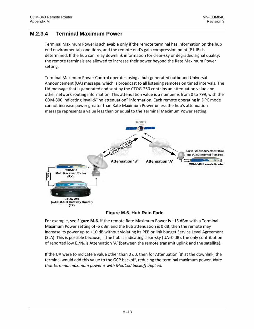
CDM-840 Remote Router MN-CDM840 Appendix M Revision 3
M–13
M.2.3.4 Terminal Maximum Power
Terminal Maximum Power is achievable only if the remote terminal has information on the hub end environmental conditions, and the remote end’s gain compression point (P1dB) is determined. If the hub can relay downlink information for clear-sky or degraded signal quality, the remote terminals are allowed to increase their power beyond the Rate Maximum Power setting. Terminal Maximum Power Control operates using a hub-generated outbound Universal Announcement (UA) message, which is broadcast to all listening remotes on timed intervals. The UA message that is generated and sent by the CTOG-250 contains an attenuation value and other network routing information. This attenuation value is a number is from 0 to 799, with the CDM-800 indicating invalid/”no attenuation” information. Each remote operating in DPC mode cannot increase power greater than Rate Maximum Power unless the hub’s attenuation message represents a value less than or equal to the Terminal Maximum Power setting.
Figure M-6. Hub Rain Fade
For example, see Figure M-6. If the remote Rate Maximum Power is –15 dBm with a Terminal Maximum Power setting of -5 dBm and the hub attenuation is 0 dB, then the remote may increase its power up to +10 dB without violating its PEB or link budget Service Level Agreement (SLA). This is possible because, if the hub is indicating clear-sky (UA=0 dB), the only contribution of reported low Es/N0 is Attenuation ‘A’ (between the remote transmit uplink and the satellite). If the UA were to indicate a value other than 0 dB, then for Attenuation ‘B’ at the downlink, the terminal would add this value to the GCP backoff, reducing the terminal maximum power. Note that terminal maximum power is with ModCod backoff applied.

CDM-840 Remote Router MN-CDM840 Appendix M Revision 3
M–14
M.2.3.5 DPC with ACM and Hub Backoff
If hub fade is known, the transmit power is allowed to increase beyond rated maximum power and up to backoff power, possibly preventing degraded performance by not modifying ModCod under ACM control.
Figure M-7. DPC w/ACM with Hub Backoff
The Figure M-7 graph depicts DPC with hub backoff: • As C/N decreases, output power increases until terminal maximum power or backoff limit is
achieved, clamping power change.
• Depending on the amount of fade, the ModCod may not change.

CDM-840 Remote Router MN-CDM840 Appendix M Revision 3
M–15
M.2.3.6 Hub Fade Control
The hub attenuation information fully optimizes power control, allowing the remote terminal to use all of available amplifier power to sustain data throughput without jeopardizing SLA. However, it can be difficult to determine if the hub downlink is in a fade condition. The problem involves measuring link quality variations from clear-sky to degraded performance, if the hub cannot receive its own uplink carrier or if the servicing satellite does not provide a beacon signal. Hub downlinks with satellite beacon signals provide the most reliable and accurate reference for realizing if the carriers from the satellite to the hub are being attenuated. A beacon receiver can measure the satellite signal and provide C/N; by reading this level, the system can set a reference of clear-sky. With a reference point established, any reduction of that signal is distributed to all receiving remotes in the service area network. To accomplish this control, the CTOG-250 sets up SNMP polling to the beacon receiver that is measuring the satellite’s downlink carrier for C/N. The periodic polled value is first stored in the CTOG-250’s reference snapshot of clear-sky condition, which sets the minimum attenuation in the UA messaging. From that “zero point” reference, any variation is updated and broadcast to all receiving remotes, providing an additional backoff value from terminal maximum. An alternate method is a collaborative approach, whereby outbound ACM remote LQRMs are collected at the corresponding CTOG-250 and stored in a table that is periodically updated. The link quality values formulate a variation in power using a statistical averaging algorithm, which the system uses to determine hub downlink fade.
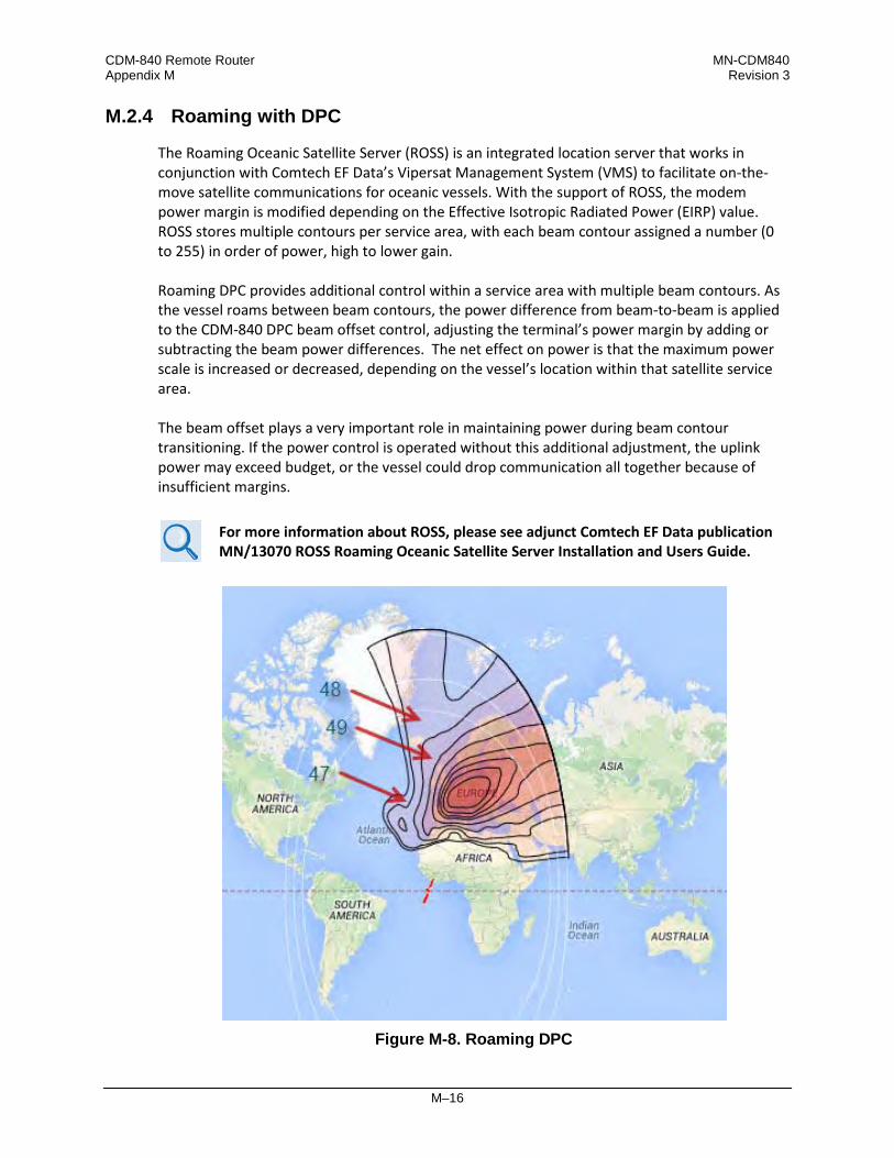
CDM-840 Remote Router MN-CDM840 Appendix M Revision 3
M–16
M.2.4 Roaming with DPC
The Roaming Oceanic Satellite Server (ROSS) is an integrated location server that works in conjunction with Comtech EF Data’s Vipersat Management System (VMS) to facilitate on-the-move satellite communications for oceanic vessels. With the support of ROSS, the modem power margin is modified depending on the Effective Isotropic Radiated Power (EIRP) value. ROSS stores multiple contours per service area, with each beam contour assigned a number (0 to 255) in order of power, high to lower gain. Roaming DPC provides additional control within a service area with multiple beam contours. As the vessel roams between beam contours, the power difference from beam-to-beam is applied to the CDM-840 DPC beam offset control, adjusting the terminal’s power margin by adding or subtracting the beam power differences. The net effect on power is that the maximum power scale is increased or decreased, depending on the vessel’s location within that satellite service area. The beam offset plays a very important role in maintaining power during beam contour transitioning. If the power control is operated without this additional adjustment, the uplink power may exceed budget, or the vessel could drop communication all together because of insufficient margins.
For more information about ROSS, please see adjunct Comtech EF Data publication MN/13070 ROSS Roaming Oceanic Satellite Server Installation and Users Guide.
Figure M-8. Roaming DPC

CDM-840 Remote Router MN-CDM840 Appendix M Revision 3
M–17
M.3 DPC Operation
Dynamic Power Control and ACM work independent of one another. This gives you the option to run DPC with or without ACM. This section assumes all other operational parameters have been previously configured.
For detailed information, see: • Chapter 6. ETHERNET-BASED REMOTE PRODUCT MANAGEMENT and Chapter 7.
SERIAL-BASED REMOTE PRODUCT MANAGEMENT in this manual.
• Chapter 6. ETHERNET-BASED REMOTE PRODUCT MANAGEMENT and Chapter 7. SERIAL-BASED REMOTE PRODUCT MANAGEMENT in the CDD-880 Multi Receiver Router Installation and Operation Manual (CEFD P/N MN-CDD880)
• VMS v3.x.x VIPERSAT Management System User Guide (CEFD P/N MN/22156)
The CDD-880 and CDM-840 provide several means for configuring Dynamic Power Control operation via Remote Product Control with a user-supplied PC: • CDD-880 and CDM-840 HTTP (Web Server) Interfaces using a compatible Web browser.
• Ethernet-based Simple Network Management Protocol (SNMP) using a Network
Management System (NMS) and Management Information Base (MIB) File Browser. • Serial-based Remote Control Interface using a terminal emulation program or Windows
Command-line.
COMTECH EF DATA STRONGLY ENCOURAGES USE OF THE CDD-880 AND CDM-840 HTTP INTERFACES FOR MONITOR AND CONTROL (M&C) OF THE CDD-880 AND THE CDM-840. COMTECH EF DATA RECOMMENDS USE OF THE SERIAL-BASED REMOTE CONTROL INTERFACE AND THE ETHERNET-BASED SNMP INTERFACE ONLY FOR ADVANCED USERS. THE HTTP INTERFACE FIGURES AS FEATURED THROUGHOUT THIS APPENDIX ARE INTENDED FOR USER REFERENCE ONLY AND ARE SUBJECT TO CHANGE. THE FIRMWARE INFORMATION (I.E., REVISION LETTERS, VERSION NUMBERS, ETC.) AS DISPLAYED MAY DIFFER FROM YOUR SETUP.

CDM-840 Remote Router MN-CDM840 Appendix M Revision 3
M–18
M.3.1 DPC Operation Using the HTTP Interfaces
Figure M-9 shows the CDM-840 and CDD-880 HTTP Interface “splash” pages, and the menu tree diagrams for accessing the operation specified in this appendix for DPC operation. Page functionality not specific to DPC operation appears dimmed in these diagrams.
(TOP) CDM-840 HTTP Interface (BOTTOM) CDD-880 HTTP Interface
Figure M-9. HTTP Interfaces – Splash Pages and DPC Operation Menu Trees (FW Ver. 1.6.2.X)
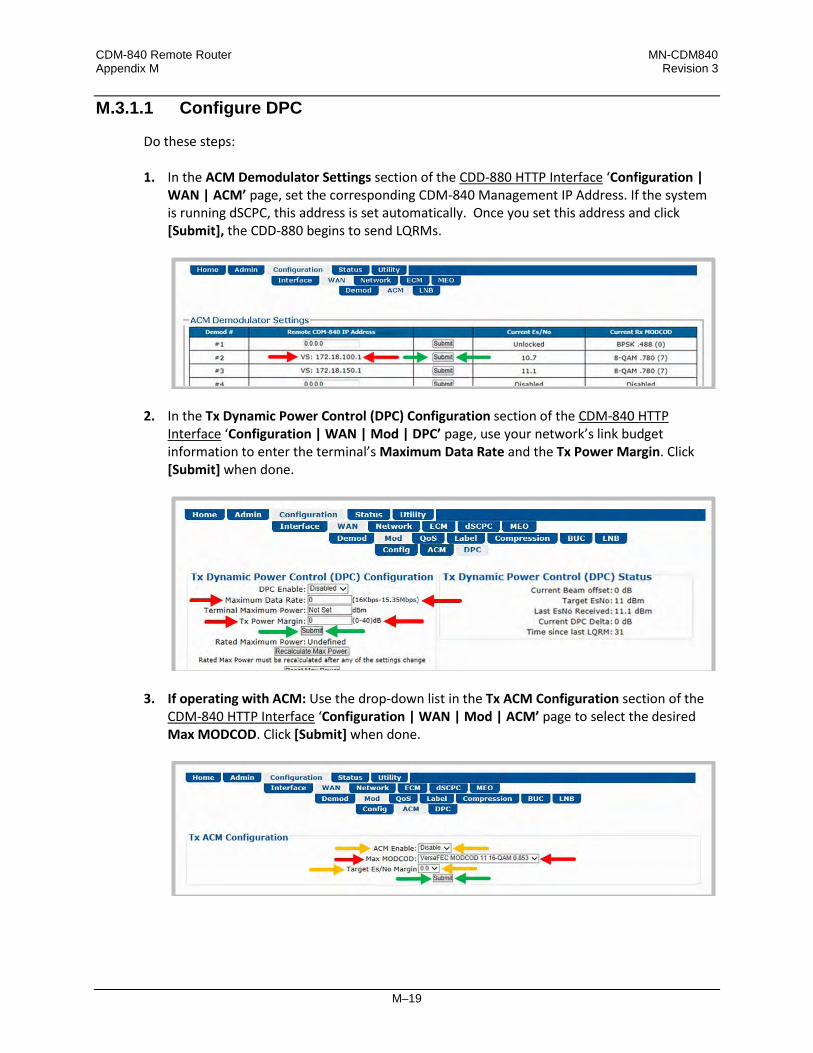
CDM-840 Remote Router MN-CDM840 Appendix M Revision 3
M–19
M.3.1.1 Configure DPC
Do these steps: 1. In the ACM Demodulator Settings section of the CDD-880 HTTP Interface ‘Configuration |
WAN | ACM’ page, set the corresponding CDM-840 Management IP Address. If the system is running dSCPC, this address is set automatically. Once you set this address and click [Submit], the CDD-880 begins to send LQRMs.
2. In the Tx Dynamic Power Control (DPC) Configuration section of the CDM-840 HTTP Interface ‘Configuration | WAN | Mod | DPC’ page, use your network’s link budget information to enter the terminal’s Maximum Data Rate and the Tx Power Margin. Click [Submit] when done.
3. If operating with ACM: Use the drop-down list in the Tx ACM Configuration section of the CDM-840 HTTP Interface ‘Configuration | WAN | Mod | ACM’ page to select the desired Max MODCOD. Click [Submit] when done.

CDM-840 Remote Router MN-CDM840 Appendix M Revision 3
M–20
• It is not important to enable ACM at this time. • Leave the Target Es/No Margin at 0.0. • Dynamic Power Control provides additional power margin for all of the
MODCOD switch points. Adding any ACM margin will deduct from the DPC power margin, which is a one-for-one subtraction.
• When operating in dSCPC, the Max MODCOD is set automatically from the Site Default MODCOD setting. The Max MODCOD drop-down list is therefore dimmed, allowing no selection.
4. Use the drop-down list in the Tx Dynamic Power Control Configuration section of the CDM-840 HTTP Interface ‘Configuration | WAN | Mod | DPC’ page to enable DPC. Click [Submit] when done.
• ACM is not required for DPC operation. • Terminal Maximum Power is left at “Not Set” at this time and will not be
applied until hub fade detection is available.
M.3.1.2 Power Reference in DPC Operation
Once DPC is configured, the power reference setting is vital to the overall operation of DPC. The reference setting is an automatic feature that requires a dSCPC transmission link between a CDM-840 and its corresponding CDD-880 at the hub; outbound communication is assumed. The link can be statically or dynamically established, and at any data rate at or below budget maximum. When calibrating the reference, the system uses the ACL to adjust power until it reaches the optimal target value. This is accomplished through an exchange of messaging between units at a fast rate – taking the set values, adjusting power, and comparing against limits before allowing the reference set to complete.
M.3.1.2.1 Set Power Reference
To set the reference, the remote must be operating with an established link in dSCPC. The link data rate can be anywhere between remote site minimum or maximum, and MODCOD is at (default) maximum.

CDM-840 Remote Router MN-CDM840 Appendix M Revision 3
M–21
1. If the link is established statically, use the CDM-840 HTTP Interface to do these steps:
a) Use the ‘Configuration | WAN | Mod | Config’ page to establish the communications link, set the Modulator Frequency, and select the MODCOD, Symbol Rate and Data Rate.
b) Manually adjust the modulator power until the return path demod locks with good data (pings).
c) Use the drop-down list in the Tx Dynamic Power Control Configuration section of the
‘Configuration | WAN | Mod | DPC’ page to enable DPC. Click [Submit], then allow power to target (ACM operation is not required).

CDM-840 Remote Router MN-CDM840 Appendix M Revision 3
M–22
d) In the Power Reference section of the ‘Configuration | WAN | Mod | DPC’ page, click [Set Reference]:
e) If [Set Reference] fails, note the failure, correct the condition, and click [Set Reference] once more.
2. If the link is established dynamically, use the CDM-840 HTTP Interface to do these steps:
a) Use the ‘Configure | ECM’ page to enable ECM with correct TAP parameters:
b) Either manually set ECM Power or enable Power Hunt to adjust power until the return
path ECM demod locks with good data (VMS registration completes).

CDM-840 Remote Router MN-CDM840 Appendix M Revision 3
M–23
c) Use the ‘Configuration | dSCPC’ page to switch to dSCPC manually (using the Load Switching Configuration section) or automatically (using the ToS Switching Configuration section).
d) Use the drop-down list in the Tx Dynamic Power Control (DPC) Configuration section of the ‘Configuration | WAN | Mod | DPC’ page to enable DPC. Click [Submit], and allow power to target (ACM operation is not required).
e) In the Power Reference section of the ‘Configuration | WAN | Mod | DPC’ page, click [Set Reference].
f) If [Set Reference] fails, note the failure, correct the condition, and click [Set Reference]
once more.

CDM-840 Remote Router MN-CDM840 Appendix M Revision 3
M–24
M.3.1.3 DPC – Status Reporting
Once reference calibration is complete, the Tx Dynamic Power Control (DPC) Status section of the ‘Configuration | WAN | Mod | DPC’ page provides information on the ongoing DPC state. Each received LQRM updates this status section; any changes to power are noted between Target Es/No and Current DPC Delta.
After the targeting of reference calibration, the DPC Delta is zeroed, and any +/- offset from this point indicates power changes due to link quality variations.
Depending on symbol rate, small rates will have variations up to ±.5 dB, even during clear-sky conditions.
Item Description Current Beam offset Current Beam offset is modified in a roam configuration, and any +/- offset
from zero either adds or subtracts from the margin or terminal maximum power backoff during a beam contour variation.
Target Es/No Target Es/No is calculated from maximum MODCOD and will remain constant unless changed.
Last Es/No Received This most recent reported value may change depending on link conditions. Current DPC Delta This represents the Adaptive Control Loop (ACL) change in power compared
to the set reference, which can increase to margin or terminal maximum power. Any decrease has the full remaining range down to -40 dBm of modulator’s output.
Time since last LQRM This is the time, in seconds, from the last power report received. Under normal conditions, the status updates every 60 seconds.
M.3.1.4 DPC – Operational Changes
DPC operation modifies the behavior between VMS site policy home state parameters and power reference control. Normally, the operator updates the home state parameter in the VMS to match the current settings in the CDM-840. This synchronizes the power settings between the two, providing correct power adjustments when the VMS sends a switch command to modify transmission rates. When you enable DPC, you now modify power with the CDM-840 and ignore any power setting in the switch command; this changes the behavior of the home state settings. The home state settings remain very important for frequency domain check, but you now use the power only to limit the site’s symbol rate. During each rate change, the VMS calculates a new power value,

CDM-840 Remote Router MN-CDM840 Appendix M Revision 3
M–25
comparing this value against the Up-converter’s power limit value; if the calculated power is less than or equal to this value, the requested rate is set. However, if the calculated power is greater than this value, the requested rate will be limited to the set limit.
M.4 Firmware Update
The order of firmware update is important – Comtech EF Data recommends that you first update the CDD-880, and then update the CDM-840.
Firmware update notes apply to systems running Firmware Versions 1.5.2.1 or lower that require the DPC feature. The DPC feature is designed not to affect any current operational settings during an update of firmware. The parameter setting for power will remain the same until reference calibration in the CDM-840 is applied, meaning that system will operate normally.
M.5 Final Considerations
DPC is not an accurate system or absolute solution. As fading varies with time, it is not possible to keep up with changes as they occur quickly. This is particularly the case when scintillation is occurring. Scintillation – when due to either low elevation troposphere effects or to the ionosphere in tropical regions – sometimes involves changes of several dB per second. When DPC is operated in combination with ACM, the system may reduce throughput during such quick changes, but regains as the loop control catches up to resume normal operation.

CDM-840 Remote Router MN-CDM840 Appendix M Revision 3
M–26
Notes:


2114 WEST 7TH STREET TEMPE ARIZONA 85281 USA 480 • 333 • 2200 PHONE
480 • 333 • 2161 FAX