cda sponsors mold design mold design guide-lines developed to make you more productive. these...
TRANSCRIPT

CDA Sponsors Mold Design Guidelines
Look for ideas that will allow
faster processing of plastic and production of higher-quality
parts
in MM&T Keep an eye out for comingissues of Modern Mold and Tooling, which will containinjection mold design guide-lines developed to make youmore productive. These infor-mative and collectable fact-filled design guidelines arebeing developed for the injec-tion molder, mold designer and mold builder. The information contained in the guide-lineswill maximize the mold's cycletime and improve part qualitywith the use of copper alloys inthe mold. The articles willbegin in the May issue. These information packedInjection Mold Design Guidelines are being developedand generated by The Copper-Alloy Molds Marketing TaskGroup. The group is a networkof copper-alloy suppliers, dis-tributors, and fabricators whohave joined together to assist
the moldmakers, molders and manufacturers to improve the processing of plastic materials.The task group, supported bythe trade associations of the copper industry, is dedicated to research and disseminatingthe information you need to take advantage of the superiorperformance of molds containing copper-alloys. Also, the association is dedicated to developing an infrastructure of copper producers, fabricators,suppliers and mold makers who are in the plastics chain.Research work, performed at Western Michigan University, is conducted to address technicalissues and remove barriers to the use of copper alloys for plastic processing. The development of these injectionMold Design Guidelines is a result of this research and in addition to empirical data derived from industryapplications.

Several molds, funded by the task group, were built and tested to conduct research under actualproduction conditions. Onestudied the cycle time advantage the copper alloys offered overtraditional mold steels.Additionally, due to the superiorthermal conductivity of the copper alloys, part qualityimprovements including less warpage, better dimensionalstability and more uniform mold temperatures resulted. Otherresearch and testing con-centrated on eliminating moldsweating under humid operatingconditions. This is accomplished by running higher mold operatingtemperatures with copper alloymold cores. The test resultsprove that better part dimensional stability can beobtained at shorter mold cooling times without mold sweating when compared with moldsteels.Exhaustive wearstudy is under wayAn exhaustive wear study is under way testing the effects of electroless nickel, hard chrome,titanium nitriting, thin densechrome and thin dense chromewith diamond particulate in extending the mold life of the copper alloys.As a service to the plasticsindustry, the Task Group is fund-ing the publication of theseguidelines in Modern Mold and Tooling. The greatest benefit to the people who deal with moldsand molding will be to collecteach issue to use as a referencein both the applications of the copper alloys and the molddesign principles.Subjects for the Injection MoldDesign Guidelines willinclude:1. Sprue Bushings and RunnerBars2. Mold Cores, Core Pins andChill Plates 3. Mold Cavities and "A" Side inserts4. Slides, Lifters and RaisingMold Members 5. Ejector Pins, Ejector Sleevesand Ejection6. Mold Temperature Control Systems, Bubblers, Baffles, Diverters and Plugs7. Wear plates, Slide Gibs,
Interlock Plates, Leader pins andGuided Ejector Bushings8. Plating and Coating of CopperAlloys9. Application of Copper Alloys in injection and Blow Molds
These guidelines will include properties of the various copperalloys most commonly utilized for their thermal and bearingproperties, compared with traditional mold steels. Charts,graphs, formulas and descrip-tions will provide the user withpertinent data not available from other sources.

Injection Mold Design GuidelinesMaximizingPerformance Using Copper Alloys
Copper Alloys for ConveyingPlastic in Injection Molds
The high thermal conductivity of copper alloys makes them idealmaterials for the injection moldsprue bushing and runner bars.Three alloys typically are utilizedfor the mold components, whichwill have contact with plastic. The copper alloys are:
• Ampcoloy 83, high hardnessberyllium-copper alloy • Ampcoloy 95, high conductivityberyllium-copper alloy • Ampcoloy 940, NiSiCr hardenedhigh conductivity copper alloy
These Copper alloys have six tonine times greater heat transferrates than conventional moldsteels as indicated by the thermalconductivity.
and runner faster, allowing moreefficient ejection or removal bysprue pickers or robots.
Sprue Bushing Radiusin North America two injectionmold nozzle and sprue bushingradii are used, 1/2 and 3/4 inch. To insure proper fit up, the nozzleradius is nominal -.015 inch, while the sprue radius is nominal +. 015inch, required tolerances to use.
Swing points and tolerances usedin establishing the radius on a sprue bushing are shown inillustration I.
Sprue Bushing OrificeMachine nozzle orifices come innominal 1/16" fractional inchsizes. To insure that the slug inthe nozzle will pull through thesprue, the orifice must be .031 (1/32 inch) larger in diameter. This dimension is referred to as the "0" dimension. The relationship isshown in this chart.
Illustration I,Sprue Radius
Mold Material ThermalConductivity
(BtU/Hr/Ft2/°F)
Ampcoloy 83 60Ampcoloy 95 135Ampcoloy 940 125H-13 17P-20 20420 SS 14
Nozzle “O" Sprue “O"
1/16" 3/32"1/8" 5/32"3/16" 7/32"3/8" 9/32"5/16" 11/32"Nominal +1/32'
The sprue or runner system mustnever control the cooling phaseand/or overall molding cycle.Plastic in contact with copperalloys will set the sprue

Also, a sprue bushing that is not keyed will rotate creating misalignment with the runnermachined into the face of the sprue bushing and the runnersystem. To prevent these problems, retain and key the sprue into position with the use of a cap screw as illustrated infigure IV.
Sprue FitHeat must be transferred from the sprue through the copperalloy sprue bushing to the mold plates, interference fit is rec-ommended for optimum cooling.The bore through the "A" plate should be nominal size to plus .0005 inches with a surface finish of at least 16 RMS. The shank of the sprue bushing should be the nominal size, plus .0005 to plus .001 inches.
Standard Sprue BushingAvailability
Copper alloy sprue bushings withpatented stainless steel nozzleseats are commercially available. An insulator between the nozzleand sprue is beneficial in controlling the flow of heat from the nozzle to the sprue. Specialsprue bushings may be constructed to suit using standard1/2 inch per foot sprue bushingtapered drills and reams. Sprue bushings with tapers of up to 3/4 inch per foot have been used for difficult to remove plastics. Care must be taken to insure that the taper is draw polished and freefrom undercuts or rough surfacesthat could hinder sprue removal.
Conventional Injection MoldRunner Systems
The shape of the runner, fullround or trapezoidal, or otherconfiguration, is dictated by molddesign. The most efficient runnercross section is full round. The efficiency of the runner crosssection can be calculated with a formula, figure V, the larger the ratio the better.
Sprue Bushing TaperTo aid in the removal of the spruefrom the bushing, a taper of one-half inch per foot is normally used in injection molding. Calculate the sprue orifice at the parting lineface, multiply the tangent of the taper angle times the length, plus the "02". Knowing this dimension,informed decisions can be madeon primary runner sizing.
The sprue frequently controls the molding cycle when larger orificeconventional steel sprue bushingsare used. The application of a copper alloy sprue bushing coolsthe sprue more quickly andefficiently, allowing the moldingcycle to be controlled by the piece part.
Pressure loss is high in the sprue.This is the only place in the feed system where the channelprogresses from a smaller area to larger. Frequently, smaller orifices are used on long sprue bushingsin an effort to reduce the mass.This results in extremely highinjection pressure losses, making the part hard to fill.
The chart in illustration lll is a guide for determining the effect that the specific "0" dimension has on the pressure required to deliver plastic through the lengthof a sprue. Note that the differ-ence between a 3/32 and 9/32-inch sprue is about 1,000 PSI over a short sprue and almost1,500 pounds on a long sprue.
Using a copper alloy spruebushing allows for an increasedsize orifice, thus reducingpressure loss while maintainingreasonable cooling times.
Sprue Retention and Anti-RotationPressure acting on the partingline face of the sprue, due toprojected area of the runnersystem or part detail, exerts pressure on the sprue bushing.
Illustration II, Sprue taper
Illustration III, Pressure,Sprue Length
Illustration IV, Anti – rotation screw
Illustration V, Formula runnersystem

Injection Mold Runner BarsRunner systems for high cavita- tion molds normally have largerdiameters due to runner balancing.The runner system extends the molding cycles as heat is slowlytransferred from the thick plastic to steel mold plates. Inserting copperalloy runner bars in the mold "A" and "B" plates, cooling the runnerfaster, is beneficial, in reducing the overall molding cycle.
Runner SizingRunner sizing is dependent on many things, including: plasticmaterial; part size, weight and wall thickness; molding machine capabilities and processing parameters and, the number and placement of the cavities.
Each mold is unique and thedesigner must consider all parameters and options availableon an individual case by case basis.Several mold design softwarepackages are available, including Mold Flow and C-Mold, whichaddress sizing of the runner system.
One method of runner sizing and balancing used by mold designersstarts at the sprue and then works toward the gate. Other designersstart with the part wall thickness andwork back to the sprue outlet orifice. The normally recommendedprocedure is that, in the direction of plastic flow, the runner area alwaysgoes from larger to smaller. Never from a smaller area to a larger area.
When the primary runner diameter is known, the sum of the areas of the multiple connecting runners must be equal or smaller in area than the preceding runner.When working backfrom the part,some designers size the final runner channel size (that runnerwhich feeds the gate) to equal the thickest wall section in the part. Eachrunner intersection then is a function of the area of that runner times the number of connecting runners,usuallytwo. Therefore, the area of the upstream runner is always at least equal to or larger in area than the sum of the branches. Note that a
runner with one-half the area is not the same as a runner of one-halfthe diameter.
Formulas for calculating the area of the runner:Runner Bar Mating
Best results are obtained byFull Round RunnerA = 0.7854 d2Trapezoidal RunnerA = (w1 + w2) h/2A = area, d = diameter, I = length,w = width, h = height
Illustration VI, Runner Barsdesigning and building the runnerbars to have zero to negativecontact with each other when the mold is closed. This will prevent any deformation on the parting linesurfaces that could result from high clamping pressures exceeding the compressive strength of the alloy.To accomplish this, the "A" and "B" runner bars should be flush to minus .001 inch on each side of the mold. This allows the mold base and/ or cavity and core inserts to receive machine clamp force, not the runner bars.
Care must be taken to understandthe characteristics of the plastic being molded and clearanceshould be short of allowing the runner system to flash. Additionally, it is important to insure that the mating halves of the runnersystem are in perfect alignment,with no mismatch at the parting line, to maximize plastic flow efficiency.
Runner Bar CoolingThe runner system must nevercontrol the molding cycle. To insureproper temperature control of the runner bars, cooling channelsshould be placed directly into the both the "A" and "B" side inserts.The cross-drilled holes should be blocked with a plug containing an "0" ring and a straight thread plug. Due to the high thermal conductivityof the copper alloys and the tendency to thermal cycle rapidly, tapered thread systems must be avoided in the copper alloys toprevent cracking.
Illustration VII
With the increased cooling rate of the copper alloys and propercooling arrangements, largerdiameter runners can be used In a mold equipped with copper alloy runner bars. Almost without exception, runner diameters one or two sizes larger can be set up quicker with the copper alloys, over traditional mold steels.
Sprue PullerA reverse taper sprue puller, 3° for stiffer materials and 5° for flexible materials, is recommended to insuresprue removal. To rapidly cool the undercut machine, the puller directly into the runner bars or a copperalloy insert. Illustration Vll givesmore details.

Injection Mold Design Guidelines
Maximizing Performance Using Copper Alloys
The Injection Mold CoreA mold core is any member that forms the interior of a plastic part, usually on the "B" side of the mold parting line. Mold cores can be machined from a solid piece of copper alloy or inserted to aid in construction or allow for easierreplacement if a component would ever be damaged in molding.
This picture shows a large copperalloy core, about 24 inches long and seven inches high, used to mold a PVC bezel for a KitchenAid dishwasher manufactured byWhirlpool Corporation, FindlayOhio. The copper alloy wasspecified primarily to eliminate warpage on the part, which is both functional and esthetic in nature. The cycle time advantage of about 20% by using the high thermal conductive copper alloy was an added bonus to the improved part quality which was the mainobjective.
Properly designed molds withcopper alloys used in strategiclocations, usually the core, haveproven to reduce injection moldingcooling cycles by 20 to 50 per cent. The mold core is responsiblefor removing from 65 to 75 percent of the heat from the
The copper alloys normally selected for mold cores, core pins, inserts, slides andraising mold members are; AA83 a high hardness beryllium-copper alloy;
plastic molding due to the material shrinking around the standingfeatures of the mold.
Copper alloys have adequatehardness levels to hold up againstnormal injection pressures found in conventional injection moldingmachines. The normal press (pos-itive interference, or crush) is not used due to the higher ductility ofcopper alloys and to avoid any peening or hobbing at shut offs andat the parting line. Rather zero to negative press is recommended.Negative press or clearance of the mating components must obviouslybe less than that where plastic will flash. Hardness levels of the copper alloys and mold steels are listed in the following chart:
Hardness LevelsCopperAlloy
Hardness
Ste
elA
lloy
Hardness
AA83 41 RC H-13 38/52 RC
AA95 96 Rb P-20 28-48 Re
AA940 94 Rb 420SS
27-50 Re
Picture of Whirlpool mold: A core built from a copper alloyfor a large dishwasher part.
AA95 a high conductivity beryllium-copper; and, AA940 a NiSiCrhardened high conductivity copperalloy. These alloys, with six to nine times greater heat trans-

fer rates than steels (see InjectionMold Design Guidelines, number 1 for details) have proven over time to be the best choices for plasticforming mold components. Other copper alloys, including the alu-minum bronzes, have attributesconsistent with specificapplications in the mold notassociated with plastic forming.These include frictional wear and guiding surfaces where theirexcellent frictional properties canbest be utilized.
Types of Core Construction
Mold cores can be machined from a solid mold "B" plate but are more commonly inserted into the "B"plate for ease of manufacture.When inserting the core, it is normally retained with a heel or cap screws. The heel on a core, see Illustration A, typicallyextending .125 for small cores and.250 for larger cores should have a length ratio of one to two times the heel for maximum strength. The corresponding counter bore is machined into the plate withclearance around the perimeter,allowing the main core body to align the insert. The depth of the heel pocket should match the insert to plus .0002 to insure that the core does not move in the molding cycle.
Other means of holding the core include blind pocketing, illustration B, or self-sealing, Illustration C. The self-sealing insert is a popularchoice for deep pocket inserting in applications where most of the part, outer molding surfaces, are formed on the "B" side of the mold. As the portion of the pocketed insert aligns the insert, the depth must be great enough to withstandany side pressures imposed in molding.
Tensile StrengthTensile strength is extremelyimportant attribute when selectinga suitable mold material, if there were a scale that measuredtoughness we would want to use
that for a mold material. The cop-per alloys exhibit a good combi-nation of tensile strength andductility, making them tough and ideal candidates for mold compo-nents, not withstanding the high thermal conductivity properties.Tensile strength of the three cop-per alloys and three common mold steels are compared in thefollowing tensile strength table.
Tensile Strength (ksi)CopperAlloy
ksi Steel Alloy ksi
AA83 190 H-13 206
AA95 110 P-20 146
AA940 100 420 SS 125-250
Illustration A: Heeled core withbubbler
Mold CoolingThe injection molding cycle ismade up of a number of elements.They include the filling portion,sometimes referred to as fill, pack and hold, the cooling portion and the mold open portion. The coolingportion is always the longest and frequently represents greater than 65 per cent of the overall cycle. Therefore, the longest element in the overall cycle is where the greatest benefit can be obtained in improving the injection moldingcycle and where copper alloyswork to your best advantage.
Illustration B: Inserted core with water channels
The principles of heat flow in an injection mold are: 1. Heat flows from the body with the highertemperature to a body of lower temperature (from the plastic to the mold component the plastic is in contact with). 2. The temperaturedifference, not the amount of heat contained, determines flow of heat. 3. The greater the difference in temperatures between the plasticand the mold component, the greater the flow of heat. 4. Radiation, conduction and/orconvection transfer heat. Conduction is the main method of heat transfer in an injection mold.
Illustration C: Self sealing core insert
The amount of heat that must be conducted from a mold can becalculated. It must be rememberedthat 65 to 75 percent of this heat must be removed through the coreof the mold. The formula is asfollows:
Illustration D: Heeled core with water passages

Where: H = Quantity of heat in Btuconducted
H=KAT(tp-tc L
K = Thermal conductivityfactor of mold material in
Btu/hr/ft2/°F/A = Surface area of mold incontact in square feet T = Time in hourstp = Temperature of plastic
tc = Temperature of coolantL = Distance from surface
of mold to coolant channel(Note: H-13, P-20 and 420 SS thermal conductivity ranges from 12 to 20, the threecommonly use copper alloys range from 61to 135)The importance that the highthermal conductivity of properties of copper alloys has in removing heat from the mold can be determinedfrom the formula. Obviously, the other elements of the formula are important considerations that must also be taken into account whendesigning an efficiently cooledinjection mold. However, changingthe mold material and the resultantthermal conductivity factor is normally the simplest and mosteffective means of achieving the best cycle time.
Coolant OptionsThe injection mold core is one of the more difficult areas to place and install the proper coolant channelsdue to the limited space availableand ejection options necessary for part removal, it is important that the coolant system be one of the first considerations made in molddesign, as the overall success of the mold project is dependant on how efficient the mold cooling cyclecan be made. The use of copperalloys and their inherent superiorthermal conductivity is the best guarantee the mold has at success.
Copper alloys will insure that the surface temperate is as even as possible and will extract heat away from the plastic part. To maintain best operating conditions and short cooling cycles, it is imperative that the heat is efficiently removed form the molds core. Coolant lines, in the form of through-drilled channels or with the use of bubblers or baffles, should be installed in the mold
core similar to a steel core. This will provide the best results and yield the most efficient cooling. Should the same coolant diameters and placement not be possible, the copper alloys are more forgiving than mold materials with lowerthermal conductivity. Typically the copper alloys will allow greater liberties in placement of coolantchannels, while cooling moreefficiently than their steel counterparts. Caution should be used to insure that adequateprovisions have been made for removal of the heat from any mold component.
If drilled coolant channels aremachined directly into the mold core, the edge of the coolantchannel should be about two times the diameter away from the molding surface. The distance between the coolant channels should be from three to five times the diameter, seeIllustration D. Positioning thecoolant channel any closer to the molding surface does not neces-sarily result in better cooling and in some cases provides a gradientdifferential in surface temperature,which could leave residual stressesin the plastic part. More details on cooling options will be presented in the sixth article in this series.
Cycle Time ImprovementsExtensive testing was conducted at Western Michigan Universitycomparing the use of the three most commonly utilized copperalloys in injection molds AA83 (A), AA95 (B) and AA940 (C) againstH-13 and 420 SS. A single cavitytest mold for a 50-mmpolypropylene closure was obtained and optimized to run at the lowestcycle time possible. Identical mold components were fabricated from the three copper alloys and steel materials. Identical processing conditions were established and each core material was tested with the only variable being cooling time.Graph A illustrates the cycleadvantages and the reduction in cooling times made by the copperalloys when compared directly to the conventional mold steels.
Each test was conducted after a controlled stabilization period. For purposes of evaluating the
Graph A: Actual comparisons of bestachievable cycle and cooling times in thesame mold, the only change was the corematerial
Graph B: Amount of part warpage Icomparedto cycle time for copper alloys vs tool steel
results of cycle time, cooling time was the only variable. The only mold change wasthe core itself. The only processingchange allowed was to cooling time. Melt temperature, cooling temperatures,injection time, gate seal and other processing conditions were monitored to insure identical conditions. This test wasperhaps the first time ever that exacting comparisons were made, under pro-duction type conditions, that physically demonstrated the advantages of the superior thermal conductivity and effects on the injection molding cooling cycle andthe resultant overall molding cycle.
Graph B compares part warpage, In millimeters, between the three copper alloys and two steel materials at variouscycle times. The copper alloys removeheat so efficiently that part warpage isminimal, even at shorter cycle times. The benefit of improving part quality at faster molding cycles over steel is obvious. However, the greatest advantage might be the better consistency imparted into the plastic parts as a result of even mold surface temperatures.

This test was conclusive, confirm-ing anecdotal experience from others where cooling cycle timeimprovements of 20 to 50 per cent are common on production molds when copper alloys are properlyutilized.
Chill Plate ApplicationsFrequently molds with smalldiameter cores, those too small for cooling lines, benefit by seatingcopper alloy core pin heads on a copper chill plate of the same alloy. When ever core size or designallows you should install coolantlines using baffles, bubblers or drilled channels, to optimize mold cooling and temperature control. When either the number of core pins or the diameter prevents the installation of the coolant channels,the chill plate concept should be considered. Testing has found that the best results are obtained whenthe core pins and chill plate have the same high thermal conductivitynumbers. Obviously the higher the thermal conductivity number the better. Coolant channels areinstalled directly into the chill plate to remove the heat and maintainthe proper mold core temperature.in small diameter cores, where sizelimitations prevent water channel is the core, this concept has beenshown to be almost as effective as cores with small coolant channels.The chill plate concept is not as effective as direct water coolingand should not be used for largerdiameter cores where directcoolant is possible, illustration E shows a chill plate application.Note, the chill plate can beinstalled under the main core orwhen using sleeve ejection,mounted to the back of the ejectorhousing.
Draft ConsiderationsThe molded plastic part must be ejected from the core. To enhancepart ejection draft, tapering of the part feature to assist in moldrelease is necessary. The draftangle specified should result after consultation
with the plastic material supplier,plastic part designer, molder andmold designer. Draft should be as generous as possible and normallymatches the draft on the cavity side to insure an even and consistent wall thickness, see Illustration F.
Ribs on the other hand present a different problem. Large draft angles results in thick wall sectionswhere the rib joins the main wall section. Normally, the junction of the rib to the wall should be one-half to two thirds of the mating wall thickness. The use copper alloys is of great benefit in these situations.The rapid removal of heat from the thicker ribs, due to the more efficient cooling of the copperalloys, will normally reduce or eliminate the sink mark, which is typically caused by the delayedsolidification of plastic at the junction of ribs at the wall of the part. Without the benefit of the superior cooling of the copperalloy, injection pressure and hold times are often extended. This not only results in longer cycle timesbut also increases the incidence of flash, warpage and over packing of the molded part. a
DisclaimerThese guidelines are a result of research at WMU and Industry experience gained withthe use of copper alloys in injection molding. While the Information contained is deemed reliable, due to the wide variety of plasticsmaterials, mold designs and possible molding applications available, no war-ranties are expressed or Implied in the application of these guidelines.
Contact informationInformation on copper alloys is available from the Copper Development Association, 1-800-232-3282.
Illustration E: Chill plate application
Illustration F: Self – sealingcore with draft

Injection Mold DesignGuidelines
Maximizing Performance using Copper Alloys
The Injection Mold CavityA mold cavity forms the exterior of the plastic part and almost alwaysis located on the "A" side of the mold. However, there are
situations where the cavity is located on the opposite sideof the parting line or occasionswhere the injection-moldedpart is symmetrical and thecavity is on both sides of the parting line. In these instancesit is called a "B" side cavity.
Cavity InsertsMolds containing more thatone cavity, multiple impression molds, are usuallyconstructed individually, or if small, ganged into cavity blocks, and inserted into the
mold "A" or cavity plate. Separate inserting allows for ease of manufacturing the cavity from a variety of mold materials andmakes replacement easier shoulddamage ever occur. Round insertsare a natural, as round insertpockets are easy to machine with great accuracy into mold plates. The round insert is an idealapplication for "surround" cooling of the insert. "0" rings are used to seal the water channels andprevent coolant leakage. They should be designed to be placed in compression and not in shear, for
ease of insert installation and leakfree operation.
Mono Block ConstructionFrequently in low run single impression and/or large molds the cavity is machined directly into the "A" plate. This type of mold construction is referred to as"Mono-Block" construction andeliminates the step of machining aninsert pocket into the plate. Additionally, it offers a very rigid type mold construction withopportunities for excellent coolingchannels surrounding the cavity.
Illustration A: Edge gate showing gatewidth (W), depth (D) and gate land (L).
Cavity CoolingCooling channels of appropriatediameter or channel size should beincorporated into the mold cavityblock. Placement of thesechannels should follow similarrecommendations made for the core of the mold. The coolantchannel should be placed abouttwo times the diameter away from the cavity with a pitch of three to five times the diameter. While it is common practice to run the cavity warmer than the core for aestheticreasons, the best running molds are those where even surfacetemperatures and goodtemperature control can bemaintained.
To insure turbulent water flow in mold cooling circuits a mold cool-ing analysis is conducted prior to mold building. This analysis checksand determines place-

run molds. P-20 or Number 3 steel is used for long runmolds and when part detail is machined into the mold plate.When a heat-treated mold plate is required, some cavity detailcan be formed on the mold plate and the cavity built up with laminations, H-13 is a logicalchoice for these high run molds.Another material used for highvolume and long running molds or with corrosive plastics is type420F stainless steel.
Cavity MaterialsWhen high thermal conductivity isrequired, either to more rapidlycool the plastic and promotefaster cycles or to maintain a more even surface temperaturefor better dimensionalconsistency, the copper alloysdesignated Ampcoloy AA83, AA95 or AA940 are used.
Gate Placement,Types and SizeGate placement, normally in the cavity, is critical to the plasticcomponent ultimate aestheticand physical properties. The ideal location will, to a degree, dictate the type and size of the gate used for the mold. The best gate location, along with the typeand size of the gate, is one of the early and difficult mold designdecisions that must be madecorrectly to insure a good runningmold.
In injection molding the morecommonly used gates are theedge, submarine (tunnel) andpinpoint gate, which constitutesabout 65% of molds built andwhich we will elaborate on. However, some parts are moreideally suited to different gateconfigurations includingrunnerless molding systemdrops, fan, tab, sprue, ring,diaphragm, flash and post gates.
Edge GatesThe edge gate is the mostcommon type of gate on conventional molds. (IllustrationA) Typically, the gate depth (d) is 50 to 80% of the wall that it is connected to. The depth of the gate controls gate freeze off and is the most critical
ment, number and size of coolantchannels required. After the mold is built coolant flow can be measuredto determine if adequate flow ratesare being maintained. The followingtable lists pipe size and minimumamount of flow in gallons per minute which guarantees turbulent flow.
Nominal PipeSize(NPT
ChannelSize(diameter)
Min.FlOW(Gal/Min.)
1/16 .250 0.34
1/8 .313 0.45
1/4 .438 0.56
3/8 .562 0.75
1/2 .688 1.30
Illustration B: Submarine or tunnelgate, diameter and angle of coneillustrated
Core Inserts in CavitiesHoles in the part and other male coredetail formed from the cavity side are normally achieved with core insertsin the cavity. Consideration has to be made for removal of heat from these components. Parts like televisionbacks with air circulation slots are idea candidates for inserting high thermal conductivity copper alloys, Ampcoloy AA83, AA95 or AA940 into the cavity, as are other hard to install coolant channels in other sections of the molds.
A pure mold cavity for an item like a drinking glass, where the plasticshrinks away from the cavity, only has to remove about 25 to 33% of the heat from the plastic. Plasticparts with contoured configurationssuch as toys sometimes are molded with 50% of the heat removedthrough the cavity. These parts benefit from the high thermalconductivity of the copper alloys and the more even mold surfacetemperatures offered.
Mold Base MaterialsAdditionally the mold plate can bebuild from the material most ideallysuited for the type and amount of cycles the mold will run. The mold plates and/or mold base are normallybuilt from 1030 plain carbon steel, Number 1 steel for prototypes or very short runs. Number 2 steel,4130-4140, is most often used for medium
Illustration C: Pin point gate, used in three plate molds

dimension in determining pressureloss. Width of the gate (w) is generally two to four times the depth, depending upon the volume of plastic required to fill the part. The gate land (I) should be short to avoid large pressure losses. Additionally, a short gate land will assist in breaking or degating the part from the runner.
Submarine GateThe submarine (frequently referred to as a tunnel or sub) gate is a popular choice on conventionalmolds when an automatic method of separating the part from therunner system is desired. The diameter of the gate (Illustration B)is generally 50 to 70% of the wall section, with 60% a commonchoice. The angle of the cone is normally 30°. However, with stiffermaterials it frequently is less. Care must be taken so as not to place the cone too close to the cavity thereby avoiding thin cavity material sections and premature failure.Flexible plastics allow the angle to increase, as the plastic will still pull from the cone. Most submarinegates are placed to enter on the cavity side of the mold. In these situations, ejector pins with pullersare incorporated in the runnersystem to hold the runner duringgate separating and then eject the runner.
Pin Point GatePin point gates (top gating) areused in modified and three platemolds. Typically, and almost with-out exception, round parts likeclosures and caps have the gate located in the center of the part. The cone, connecting the runnersystem with the gate starts with a full radius at the end and typicallyhas a 2°-3° angle to assist in extraction with the assistance of a sucker pin. The gate portion tapers down at about a 10° angle. The intersection of the gate to the cavity must be sharp providing for a good break off. Generally, the amount of gate projection from a pin pointgate is one-half the gate diameter. The gate diameter (Illustration 0 is 30 to 60% of the wall that it is connected to. The ideal gatediameter is a function of the flow properties of the plastic; the easierthe flow the smaller the gatediameter. The harder the flow, the
larger the diameter. Obviously, the smaller the gatediameter the better the cosmetics on the part and the smaller the gate vestige.The ideal location for the gate is listed below, unfortunately, sometimes trade offs must be made and not every criteria can besatisfied. Therefore, a decision hasto be made as what is the best compromise in gate placement. 1. Plastic must have the ability to fillthe entire part without usingextreme processing conditions andmaximum injection pressures. (Multiple gates may be required onsome parts) 2.Material, flowing from the gate, will push gasses toward the parting line or other areas where they can be effectively vented and will not entrap gas. 3. Plastic will flow into the thickest section of the part and will flow from thicker to thinner sections. 4. Flow to all points on the part will be of equal distance and the part will not experience areas of over packing.5. The gate must be located in an area not subjected to high stressesdepth, information available from the plastic material supplier is a very reliable source for technical information.
VentsVents (Illustration D) should be installed at the mold parting line. The depth should be slightly less then where flash will form. Vents should be 1/4 to 1/2 inch in width. After a short land length, typically .020 inch, the vent depth should bemachined .03 to .04 deep and must lead to atmosphere outside the mold. Conventional runner systemsshould be vented also. Any gas that can be vented prior to arriving at the cavity is less volume that has to be allowed to escape. Typically runnersystem vents are twice the depth asthe part if runner flash is not an issue and installed at the end of the runner and at junctions. Stoppingshort of the outside of the mold with any vent is extremely inefficient in allowing gasses to escape andconsidered bad practice.
Round parts with top gates,(Illustration E) lend themselves to relief around the entire part. A collector ring assists in collecting
(the gate area could well be the
weakest section on the part). 6. Plastic entering the part from the gate must impinge on a wall or moldmember to create a small backpressure, avoid jetting. 7. The location has to be in an area that will minimize weld, flow or knit lines especially on class "A" surfaces. 8. The gate mark should not be located on anappearance or functional surface. 9. If the gate is of the type that must be trimmed, it must be located in an accessible area.
Methods of ventingInjection molds must be vented to allow volatiles released from the plastic pellets during the plasitifi-cation process and the air trapped in the closed mold to escape. Adequate vents must be installed on the parting line, runner systems and in any place in the mold where entrapment of these gasses occur. The depth of the vent must be less than that which the plastic will flash. Experience has proven that the location of the vent in proximity to the gate will determine the depth to which plastic will flash. The closer the vent is to the gate the easier the material will flash. The longer the flow distance from the gate, the less likely plastic will flash at the same

stone or blasting. These cate-gories then have three sub-groups defining the last benching or polishing operationthat will yield the desired finishor appearance on the plasticpart. in addition to the listing of the SPI finish standard numberand the correspondingoperation, we have included the Ra and RMS measurementtaken from a finishedcomponent. It is important to remember that the measurementis not part of the SPI standard,nor is it endorsed by SPI. It issimply included as a reference.
the gasses and bleed offs allow them to escape to atmosphere. The volume of the bleed offs mustequal or be greater than thevolume of the collector rings to be efficient.
Areas in the cavity that can be vented other than the parting line are at insert lines, core pins and areas where sintered vents canbe installed. Ejector pins are often overlooked as excellent places to install vents, as they are selfcleaning due to their movement at ejection. An effective vent can be achieved by grinding relief on the top diameter (Illustration F) to allow the gasses to escapearound the diameter to a collectorring and then spiral bleed offs to the ejector housing. This methodkeeps the ejector pin centered in the ejector pin hole, preventingshifting of the pin causing flash onone side of the pin and shuttingoff the vent on the other side and is much more effective than an under-size pin in an oversizedejector pin hole.
Mold FinishThe Society of Plastics Industry(SPI) developed and publishes a standard for mold finish that is universally used to specify the desired effect on the plastic part. The standard is based on fourdifferent methods, polishing withdiamond, paper,
SPIFinish
Definition of Last Operation
Ra RMS
A-13 Diamond Buff 0.6 0.8A-26 Diamond Buff 0.8 1.0A-315 Diamond Buff 0.9 1.2B-1600 Grit Paper 2.1 2.6B-2400 Grit Paper 3.8 4.9B-3320 Grit Paper 4.8 6.2C-1600 Stone 4.4 5.7C-2400 Stone 8.0 10.2C-3320 Stone 8.9 11.4D-1 Dry Blast #11 8.8 11.1D-2 Dry Blast # 240
Al Oxide13.2
17.0
D-3 Dry Blast # 24 AlOxide
80.8
104.5

Injection Mold DesignGuidelines
FOURTH IN A SERIES: NOMENCLATUREMaximizing Performance Using Copper Alloys
Nomenclature for the types of moldsis somewhat diverse but usually follows an order describing the typeof runner system, mold action andejection method used. A mold is considered a standard mold when it has a conventional runner system,the part is pulled without any actionand the mold only has an opening atthe parting line. Occasionally we hear the term two-plate applied to this type of conventional mold. Thisis not necessarily a correctdescription and perhaps is only usedto differentiate it from a three-platemold.
A three-plate mold has the runnersystem installed between a separateparting line and the parts are gatedwith a pin point gate. The advantageis that the cold runner is separatedfrom the parts on mold opening. Thistype of mold was popular for topgating parts and now frequently arunner-less molding system is used in its place.
Runnerless molding systems (RMS)account for nearly 30% of the moldsbuilt today. RMS can be internally orexternally heated. If internally heated, the mold has distributor tubes and/or probes with electricheaters placed in the distributionchannels to maintain the melttemperature of the plastic as it flows around the tubes toward the gate. Each cavity needs at least
one probe to feed plastic for the mold to be a true runnerless molding system. Often hybrid systems areused, especially on small partswhere one probe is used to feed a conventional runner system, whichthen feeds multiple parts. Copperalloy probes have proven to hold more even temperature profiles thansteel alloys, especially at the tip end.
Internally heated systems incorpo-rate a manifold with balanced and streamlined passages installed forthe plastic to flow from the inlet to the nozzles. Nozzles normallyequipped with coil heaters aroundthe periphery and a thermocouple to control the temperature, feed plasticfrom the manifold to the gate. A very popular divergent flow styleincorporates a copper alloy tip,usually made from AA83 or AA940 copper alloy, to aid in maintaining an even temperature profile at the gate entrance to the cavity. The melt flow typically diverges from the centerflow passage through orificesallowing the copper alloy tip to extend down to or into the gate orifice. The tip then maintains control of the gate area, freezing the gate during part removal and maintainingthe correct temperature to open the gate for the next cycle.
Molds can have many actions, depending on what has to be accomplished, to free undercuts and remove the part from the mold.External threads for example, if hot strippable, utilize slide action or expandable cavities to free external features.
Illustration A: Stripper ring ejectionof an undercut

Internal threads can be formed on collapsible cores or in unscrewingmolds. Several methods are usedfor unscrewing molds, including hydraulic motors, splines, variousgearing methods and for largemultiple cavity molds, racks and pinions are used.
Other mold actions include lifters,wedges or slifters (a new term), raising members and slides(sometimes referred to as splits,cams and side action). Moldnomenclature then typicallydescribes the type of ejector system used, normally ejectorpins, sleeves, stripper rings or plates. Therefore, molds are normally refereed to as "a threeplate, slide action sleeve ejectedmold", or "runnerless collapsiblecore, stripper plate mold".
Mold SlidesUndercuts, features on the plasticpart that are not in line withnormal mold opening, are fre-quently encountered. When the undercut is small, typically defined as a percentage of the overall part dimension, the best and least expensive option is to determine if the part will flex enough to strip off the cavity or core without the use of a mold action. Freeing the plasticundercut is first dependent upon the plastic material, its flexibilityand hardness. The greater theflexibility and more compressivethe plastic the greater the undercut can be. The stiffer andmore rigid the plastic material, the less the undercut must be. Undercuts are defined as the percentage difference between "d", the amount of the undercut,and "D" the diameter ordimension that the undercut has to snap off (see Illustration A).
Seals are molded from flexiblePVC with undercuts greater than .375 inch and a 1.500 diameter,resulting in undercuts of 25%. Modified Closure Manufacturer'sAssociation (CMA) threads are frequently stripped on closuresizes above 24mm in polyethyl-ene and polypropylene, especiallyin co-polymers. Acme or buttressthreads typically will not strip due to the sharp and flat thread profileperpendicular to the direction of draw.
External part features, thosenormally found on the cavity
side of the mold, require that the core be removed prior to attempting to free even the slightest undercut, as the flexing plastic must have a place to compress or expand into if the part is manufactured withoutmoving mold members. When the undercut is too great, the mold cavity can be split or mov-ing cams installed to release the undercut. These plastic part fea-tures with details connected to the main wall tend to have the thickest sections. Copper alloyswith their ability to cool fasterthan conventional mold steelshave proven to be the bestchoice of mold materials in these areas, copper alloys will provide the most even surfacetemperatures necessary to takethe heat away from the molding surfaces. Frequently, the front of the slides are faced or inserted. A copper alloy is inserted on a steel slide carrier and coolant channelsare machined through the carrierinto the copper alloy insert. With this design, the copper slide face acts as a watered heat sink,drawing heat away from the part.
In all other designs the slideshould be designed with thesame concept and mold coolantchannel as the molds cores and cavities. The coolant channelscould include looping flow, baffles or bubbles. A coolant-circulatingcascade is available from anumber of standard mold com-ponent supplies and is ideal for getting coolant into hard to reach areas like those found on a slide. The best practice is to placethese coolant lines about two diameters of the cooling channelaway from the molding surfaces.This standard works well with the copper alloys, as well as moldsteels. However, if you cannot get that close to the mold surface, the more efficient copperalloys, with their higher thermal conductivity, will perform well when the coolant lines are notideally located.
Mold LiftersA lifter is a component in the mold that is normally attached to and actuated by the ejector system and moves at an angle to free internal molding detail (see Illustrations B and C). They are typically attached between the ejector retainer and ejector plates with some mechanism
Illustration B: A lifter shown with the moldclosed. Lifter angle is exaggerated, should notexceed 5°.
Illustration C: lifter actuation shown duringejection.Lifter angle is exaggerated, should not exceed 5°.

allowing the fixed end to slide or pivot to compensate for the move-ment of the lifter position as it moves at the desired angle. Lifters are frequently used when segment-ed plastic undercuts (raised mold core detail) is necessary. The lifter has to move out of the mold core at an angle, typically 5° or less, to clear the plastic from the mold lifter detail. This angle is critical for two reasons. First, if the angle were too great the forward motion of the ejector system would put too much pressure against the lifter body.This pressure would create binding of the lifter and lead to excessive wear or premature failure. Should the angle be too shallow, the ejector plate travel would beexcessive. Therefore, carefulengineering and good judgementhas to be made.
Due to their function, lifters are nor-mally long and narrow. Coolantchannels are nearly impossible to machine into them. The AA83, AA95 and AA940 copper alloys,normally used in the mold cavity and core, will remove the heatefficiently from the lifter. However, because this is a high wear area and when the mold core is builtfrom one of the alloys already,aluminum bronzes make excellentchoices for lifter materials. Moreinformation on aluminum bronzeswill be included in article eight of this series. To avoid seizing the lifter, one copper alloy ridingagainst another copper alloy is not good engineering practice. One of the components should be plated or coated. The plating or coatingshould be carefully chosen, as it must provide a low coefficient of friction between the two surfaces.Surface treatments should provide dry lubrication and not be affectedby contact with the plastic material and thermal cycling of the mold component due to the molding process.
As the lifters have to move inward from the inside wall of the plasticpart to free the undercut, the part must be devoid of any detail that would prohibit or impede liftermovement. Should the part designnot allow this required movement the only choice to form this part detail may be with the aid of inter-nal or hidden slides. The problemwith internal slides is the amount of room they take to position and but when moved forward free movethem in a core.
Wedges or Moving Members
Wedges are mold components that have a shape that allows them to fit tight in the molding position but when moved forward freethemselves from the pocket to move away from the plastic wall (see illustrations D and E). They have a guiding system allowingthem to move forward and awayfrom internal or external undercutson the plastic part. The wedges are normally located on the "B" side of the mold and are either pulled with a mechanical attachment from the "A" side of the mold, or pushed by the ejector system or cylinders.While less common, wedges can be installed on the "A" side of the mold.
The wedge must be guided as it moves forward. The two guide sys-tems most frequently encounteredare the "T" slot or dovetails. Moldswith wedges utilizing dovetails to guide and hold the wedge in posi-tion are being called "slifters" in the tooling community. Wedges or slifters have a commonality with lifters. The angle in which they raisemust be steep enough to free the undercut within the movementrange and yet shallow enough so as not to bind or be exposed to conditions where excessive wear could occur.
By design, these mold membershave large areas in contact with the plastic part. Therefore it is necessary to build them withcoolant channels and frommaterials with high thermal conductivity rates. While thesewedges and slifters are ideal candi-dates for the AA83, AA95 and AA940 copper alloys for the plasticforming contact areas, they are not the best choices for the "T" or dove-tail guiding systems. Therefore, several options should be considered in their construction.One preferred method is tolaminate hardened tool steel to the copper molding face and install the guiding system in the tool steel. Aluminum bronze materials can be laminated to the opposing memberof the mold to reduce friction and avoid common tool steels acting asbearing surfaces.
Raising Mold Members
Occasionally plastic parts will have extreme contours. Automotive "A", "B" and "C" pillars, for example,which have geometry where the only way to free the part is to raise
Illustration D: Wedge/”slifter” with the mold closed.
it out of the mold and physically or mechanically flex the plastic to remove it from the mold core. These molds arefrequently considered raising coremolds. This type of arrangementcomplicates the installation of coolant channels due to their contour and shape. Placement of the coolant channels can be far from ideal.Typically a tool steel core member in these applications results in areaswhere cooling is compromised. Copperalloys have proven time and again that they will, due to their high cooling rates, run cooler and have more evenly distributed surface temperate than a steel counterpart would have. The plastic product almost always has less warp, twist, sink and is more dimensional consistent, due to improved temperature control of this raising mold member.
Other Mold Movements.
The injection-molding machine providesone movement when the machineplates separate. The subsequent mold opening provides the mold designerwith motion that can be used to mechanically create movement in another plane. Plate movement, commonly referred to as floating of the plates, creates the conditions where the desired mold actions can beincorporated.
One example is the movement of conventional mechanical slides on the "B" side of the mold with an angle pin(see Illustration F). The angle pin(s) islocated on the "A" side of the mold andwhen the parting line separates the pin, due to the angle, moves the slide out. If the same movement is required on the "A" side of the mold the problem of clearing the undercut prior to the main parting line must be overcome. One solution may be to pull the slides with hydraulic or pneumatic cylinders prior tothe mold opening. If the slide has plasticforming projected area against it the cavity pressure must be overcome by some locking method.

Should the area and pressures be small the cylinder may have enough force to prevent move-ment. If the pressures are great, then a locking cylinder must be used. in any event, the timing of the cylinder retraction and advancement must be tied intothe molding machine and mea-sures taken to insure that the slide is in the proper position on mold opening and closing.
To move the "A" half slides mechanically a mold movement has to be established where the "A" plate floats (retaining the plastic part) creating forwardmovement so that angle pinsmounted in the top clamp platecan actuate the slides away from the part and clearing the under-cut. Once the part is clear fromthe slide the plate movement is positively stopped, normally with shoulder or stripper bolts, and the main parting line is allowed to open.
The movement of plates is typi-cally accomplished with a pullermechanism. Frequently external mounted commercially availablelatch lock devices are mountedon the mold. These mechanismsare solidly attached to the mold member that will be actuating the plate and the opposite end of the device will contact and lock the plate when moving it and releasewhen the desire travel has beenreached.
TimingThe expression used to describethe proper sequence of events in mold action is timing. The opening and closing of a stan-
dard mold is straight forward, the sequence of events is that the mold closes, plastic is injected, the plastic is cooled, the mold opens, the parts are ejected and the cycle continues. When mold actions, items like slides, lifters, wedges, floating plates, etc. are incorporated, the sequence of events must be pre-determinedand the mold designed and built to insure that the proper eventhappens and that the plate or movement has traveled thecorrect amount prior to the next sequence starting. Additionally, it is important that the mold actionsreturn in the proper order. Over the years, almost any action or movement has been installed in production molds. We are onlylimited by our imagination on howto positively insure that the proper mold action will take place at the correct time and thenreverse the process to preparefor the next molding cycle.
There is no room for error insequencing of mold actions. Each operation must be preciselycarried out in the propersequence with the movementrequired exactly carried out. If any plate or action is left to chance, damage will occursometime during the molding run. The correct way to design themold is to positively achieve the desired movement at the right time, while providing a method of determining that the sequencehas occurred prior to allowing the mold process to continue to the next step.
Illustration E: Slifter actuation duringejection, showind the wear plates anddove tail guides
Illustration F: Copper faced slide showing the use of an angle pin. The cooling circuit pathand “O” rings between copper and steel are not visible in this view.

injection Mold DesignGuidelines
FIFTHINA SERIES
Maximizing ,Performance UsingCopper Alloys
By Dr. Paul Engelmannand Bob Dealey
for the Mold Marketing Task Croup of the Copper Development Association^
Illustration A: Core pin forming a holeIn the plastic part. The core pintransfers heat to a chill plate for faster cooling cycles.
Copper Alloy Core PinsThe fastest, easiest and quickest method ofproving benefits from the high thermalconductivity properties of copper alloys is toreplace a core pin in a troublesomeapplication. Core pin, as the name implies,forms the interior of a plastic part feature.Problem areas in the mold that will benefitfrom the core pin replacement Include heavywall sections that control cycle time, interiorpart features that cannot be cooled efficiently,sections prone to sink marks and features thatrequire tighter and more consistentdimensional control. (illustration A)
The principles of heat flow should be understood and applied in theinjection mold design as the moldacts as a heat exchanger during the molding cycle. Those principles are: 1. Radiation, conduction and convection transfer heat. (Conduction is the main method of heat transfer in a mold and is the
most efficient means of cooling) 2. Heat flows from the body with the highertemperature to a body of lower tem-perature. (You cannot transfer cold). 3. Thetemperature difference, not the amount of heat contained, determines flow of heat. 4. The greater the difference in temperaturesbetween the bodies, core and plastic, the greater the flow of heat. 5. The thermalconductivity of the mold materials will havea dominant affect on the amount of heat energy transferred.
The following mold-cooling formula is normally used for engineering molddesigns for efficient operation:

ference between them. The fitdimensions and tolerances of core pins are critical to the success in their function in the injection mold. Core fit at its mounting surface, is typically aninterference fit of -.0000 to -.0005depending on its size and frequency of removal from the mold. As a generalrule the length of the fit area should beat least twice the diameter.
As the core pin forms Its detail in the surrounding plastic, the heat given off from the plastic must be absorbed andtransferred through the core pin to an area of the mold where the heat can be transferred Into cooling lines. As withtool steel cores, the most efficient
Chart B: Chart illustratesadvantages of copper alloys inreducing part warpage and cycletimes.
had less warpage than the partmolded with a steel core with watercirculating, even at a 22% longer molding cycle.
From the Western Michigan University test data one can conclude that "L" is rather insignificant when the combination of the copper alloy core pins and chill plate of the same material andthermal conductivity is used in a mold design. This is an important discovery and technologyimprovement in the efficiency of mold building and injection molding.
Coefficient of ThermalExpansionThe coefficient of thermal expansion must be considered when designing molds withmaterials that expand at differentrates. The degree of thermal expansion is critical in both the fit of the components and the correctdimensions to design and build the mold core, components and cavity. Copper alloys have larger expan-sion coefficients than tool steels and are listed in Illustration C.
Both the plastic material shrink rate and thermal expansion of the mold cavity and core must be taken into consideration in the design of close tolerance molds. Plastic shrinkrates, when using copper alloys in the mold, may be reduced whencompared with steel components. If the plastic material shrink rate is affected by mold temperature, thencompensation must be made. Typically, the mold surface temperature will be moreconsistent and lower with the useof copper alloys, if the mold will be run at elevated temperatures, as is the case with many of the hewengineering grades of materials, the thermal expansion of mold cavities and cores must be considered when specifying mold sizes. This same consideration should be taken into account wheninserting a copper alloy into a steelretainer. The final fit should be calculated at operating temperatures.
Ejector Sleeves and Core Pins Core pins fitting into ejector sleeves requires specialconsiderations. Standard offthe shelf ejector sleeves arebuilt to accept pins with toler-ances applicable to ejector pinsand not core pins. Apparentlywhen ejector sleeves were firstintroduced the only closetolerance pins available wereejector pins and the precedentwas established. As ejector sleeves are utilized to force plastic off mold detail, it impliesthat a core pin should be usedin the application. The core pinmust rapidly transfer heatremoved from the plastic to another part of the mold. Thehigh thermal conductivity of copper alloys performs this function efficiently and
Mold Material andDescription
Coefficient of ThermalExpansion 10-6/F
Applications in Molds
420 SS Stainless Steel 6.1 High Gloss Cavities
H-13 Tool Steel 7.1 Hardened cavities and CoresP-20 Tool Steel 7.1 Pre-Hard CavitiesAmpcoloy 83 9.7 Cores, Core Pins, Cavity inserts,
Slides, Etc. Where Higher Hardness is Desired
Ampcoloy 95 9.8 Cores, Core Pins, Cavity inserts,Slides, Etc. Where Higher ThermalConductivity is Desired
Ampcoloy 940 9.7 Cores, Core Pins, Cavity inserts,Slides, Etc. Where Higher ThermalConductivity is Desired
Ampco 18 9.0 Lifters, Bushings, Bearings, Wear Plates, Gibs and High Wear Areas
Ampco 21 9.0 Ejector Sleeves, Bushings, Bearings, wear Plates, Gibs and Load BearingAreas
Illustration C: Chart listing various mold materials, coefficient of thermal expansion and applications, in injection molds.
removing the heat is with an internalcoolant passage with cooling mediumcirculating in the core itself.
Tests at Western Michigan universityhave proven the effectiveness of transferring heat from the plasticthrough a copper alloy core pin and then into a copper alloy chill plate.(Chart B). in this illustration, the results of exhaustive testing in the same mold are shown; steel and cop-per core pins with and without watercirculating in them were tested. Thetests prove the effectiveness of core pins made from copper alloys, withhigher thermal conductivity rates than tool steels, will cool a part faster withfar less warpage at shorter cycletimes than their steel counterparts.Note that the warpage of a partmolded with copper alloy core pins, resting on a copper alloy chill plate,

results in a very consistent and uniform shot-to-shot component temperature.
Care must be taken to provide the proper clearance between the ejector sleeve and copper alloy core pin.Always check your ejector sleeve supplier's dimensions and tolerances,the ejector sleeve has an internaltolerance of the nominal dimension +.0005 -.0000 inches. The copper alloycore pin should have approximately.0010 to .0015 clearance, dependingupon the diameter and at whatclearance plastic will flash. Copperalloy core pins can not just automatically be used with standardejector sleeves as the tolerances do not allow enough clearance and galling of the components will result. Proper consideration must be made inproviding the proper sliding fit.
The other design necessity is to insure that the proper bearing length betweenthe ejector sleeve and core pin is used. (Illustration D) Bearing length should bea function of the core pin diameter. Thegeneral rule of thumb is that the bearing length should be two times the diameter. We think when the bearinglength exceeds one-half to three-quarters of an inch, problems will occuras a result of too great of a bearinglength. Experience in the mode offailure between the sleeve and pin show that 90% of the time the bearinglength is too long. Standard ejectorsleeves are provided with allowancesfor cutting to the desired length and thebearing length is purposely long to accommodate all possible sleeve lengths in that size range. Therefore,when the sleeve is cut for just a short length, the bearing length is long andthat is generally when problems occur.
Copper Alloy Ejector SleevesThin wall ejector sleeves built from Ampco 21 aluminum bronze and thenplated are successfully utilized in highspeed and high cavitation unscrewingmolds. The sleeves offer advantagesover their H-13 counterparts as theyprovide an extremely low coefficient of friction. More importantly, they hold their roundness better in thin wallsleeve applications. Diameters of 2.000 inch with wall thickness of .040 inch in the ejection area have been known to run 1,000,000 cycles. When the platingbegins to show evidence of wear or exposes the copper alloy the mold components are stripped, refit and plated again. Due to similar materials, it typically is not a good practice to run copper against copper in ejector sleeveapplications. However, with the properplating on both components, success has been achieved in high volumemolds.
Copper Alloy Ejector and SpruePuller PinsThe placement of ejector pins, sleeves rings or bars in the mold is crucial tothe efficient removal of the plastic part.
First and foremost, the ejector component must push the plastic off the mold member. Placing an ejector pin ona surface that creates a pulling actionon a plastic wall results in a greaterresistance to the removal of the part.
Ejector and sprue puller pins built fromthe copper alloys, AA83, AA940, A18and A21 are successfully used in highvolume molds. The copper alloy ejectorpins require slightly greater clearancesbetween the pin and the ejector pinholeto compensate for their higher thermalexpansion. These pins work well whenadditional heat must be taken away andhave proven beneficial when used inthick wall applications for reducing oreliminating sink marks.
One of the most impressive successstories involves the use of a copperalloy sprue puller pin. (illustration E) Problems are frequently encountered in cooling the sprue puller enough to efficiently pull the sprue. The use of the copper alloy sprue puller is highlyeffective and recommended whenflexible materials are molded andproblems pulling the sprue areencountered. Again, the bearing lengthon the sprue puller pin should be twotimes the diameter of the pin.
The most common mode of failure of an ejector pin is galling created by overlylong bearing lengths. This failure modeis typically observed when a tensilefailure occurs. (Illustration F) Buckling of ejector pins is the second most common mode of failure.
When small diameter pins are used, whether in steel or copper alloy,stepped ejector pins should be used for maximum resistance against bending.Euler's Formula for long and slendercolumns can be used to determine howlong an ejector pin can be in relation to its diameter. Most ejector pin failuresoccur, due to the column being slenderwhere bending or buckling actionpredominates over compressivestresses.
Ejector Rings, Bars and Air PoppetsWhen concerns regarding wear of ejector components are encountered,copper alloy stripper rings or bars can be used. The ductility of the copperalloys, along with the low coefficient of friction between them and tool steels make them ideal candidates for these mold components. Stripper ringsinserted into guided steel stripper platesdesigned with minimal clearance resultsin long maintenance-free operation, inthe event of the plate cocking or shifting of the core, damage to the expensivemold component can be minimized withthe use of the copper alloys.Additionally, the hard-to-cool area of the stripper plate
Illustration D: Bearing length of ejector sleeves should be no greaterthan two times the diameter.
contact surface is accommodated nicelyby the high thermal conductivity of the copper alloys.
Ejector bars, similar to ejector rings but straight, are being used to contact long wall sections and are replacing the large number of small diameter ejector pins commonly used. This concept, using the low friction properties of the aluminum bronze copper alloys,provides a robust means of ejecting onlarge surface areas. Fewer ejector pin impression marks are encountered at shorter cooling and cycle times with theuse of ejector bars.
Head Clearances for Ejector Sleevesand PinsTo allow for any misalignment in machining of the multiple plates in the mold and to compensate for anyadverse thermal expansion, clearancesmust be provided for the ejectorcomponents in the mounting area. Thecounter bore depth in the ejectorretainer plate for the sleeve or pin headshould be .001 inch greater than the actual head dimension. This allows thefixed end of the column to seek its proper alignment in relationship to the corresponding hole in the mold core.
The head counter bore diameter shouldbe .015 inch larger than the sleeve or pin head diameter. Through clearancein the ejector retainer plate for the sleeve or pin shank should be .005 inch. These clearances will hold the head end of the ejector componentsecure, yet allow enough movement to not create binding when the device tries to seek its own location.
Clearances through the support and "B"plate should be .032 inch greater than the ejector component diameter. Each plate leading edge should be countersunk with a 45 degree taper for ease of assembly and to preventdamage to the outside edge of the ejector component. The mold should be assembled with the ejector plate sepa-rated from the ejector retainer plate. Each ejector sleeve or pin should be indi-

Illustration E: Copper alloy sprue puller pin used to firm up puller and reducemolding cycles.
vidually positioned and loaded into its proper location. The components,once committed to a location, shouldbe properly identified and alwaysreturned to that position.
Guided Ejector SystemEvery mold that utilizes small diam-eter ejector pins or is heavy enoughto cause the pins to flex should be equipped with a four post-guidedejector system. The most efficient systems utilize hard surfacegrooveless leader pins and Ampco 18 or Ampco 21 aluminum bronzebushings. The guides should be located on the four corners of theejector system to provide the mostaccurate alignment of the compo-nents to the mold core. The objectiveis to remove any load from the ejector components. Debates range if the leader pins should be installed in the ejector housing or through the support plate. We prefer installing the guide pins in the support plate as this allows the ejector retainer plate to be held in position when the ejectorcomponents are loaded. In those instances when the supportplate will be subjected to greaterthermal expansion than the ejectorplate, additional clearances can be accommodated in the fit of the bush-ings to the ejector and ejector retain-er plate. Placement of the guide pinsin the ejector housing removes the element of thermal expansion fromthe equation, but makes it more diffi-cult to assemble the mold.
Ejector System ReturnEvery mold should have ejectorreturn pins to insure that the ejectorsystem has positively returned for the start of the next cycle. The most common method is using the stan-dard four return system found on every standard mold base. This posi-tive method of ejector plate return,with the pin head resting on the
ejector plate and the tip located at the parting line, only ensures full return when the mold is closed. Frequently, it is desired to either take the load off the return pins or assistin the return of the ejector system.Connecting the ejector system to the machine's hydraulic knock out plates with an ejector rod is common. Whenthe machine ejector system returns,the ejector plate and ejector systemalso returns.
Many molds incorporatecompression springs to aid in the return of the ejector system. Foursprings, often located around thereturn pins, are used. Care must be taken not to over compress thesprings and cause premature failure.This method is not entirely fool proof. The ejector system is not positivelyreturned after each cycle and shouldnever be used as the only means of return if damage will result should an ejector component not be returnedprior to mold closing. Ejector return springs should be replaced in sets, never individually to ensure that evenpressure is supplied against the ejector plate.
When the ejector system must be absolutely and positively returnedprior to the mold closing, early ejec-tor system mechanisms are used.Small molds sometimes use internally mounted early ejectorreturn systems. Medium and largemolds use externally mounted toggle mechanisms to ensure that theejector plates have been positivelyreturned so they will not prevent the mold from closing.We believe that having a limit switchor electrical signal to ensure thepositive return of the ejector systemis an important safety consideration.Using a switch alone, without theassistance of an early return system,can be dangerous and result in mold damage should a system electricalfailure or false signal occur. •
Illustration F: Bearing length of ejector pins is crucial to mold life.
AcknowledgementsThe Injection mold design guidelines were written by Dr. Paul Engelmann, Associate Professor, western Michigan university and Bob Dealey, Dealey's Mold Engineering,with the support of Dr. Dale Peters, for the Mold Marketing Task Group of the Copper Development Association. Kurt Hayden, graduate research assistant, WMU,generated the Illustrations. Research conducted by WMU plastic program students.
DisclaimerThese guidelines are a result of research at WMU and industry experience gainedwith the use of copper alloys In injection molding. While the information contained is deemed reliable, due to the wide variety of plastics materials, mold designs and possible molding applications available, no warranties are expressed or Implied in the application of these guidelines.
Contact informationInformation on copper alloys is available from the Copper Development Association,at 800-232-3282. Technical clarification of the guidelines can be made by contacting Bob Dealey Dealey's Mold Engineering at 262-245-5800

Injection Mold DesignGuidelinesSIXTH IN A SERIES
Maximizing Performance using Copper Alloys
ejected correctly without harming the part. Normally we think of the process as just cooling of the mold, but sometimes the mold is heated.Our ultimate objective is to controlmold temperature within a range that yields a product within specificationsat acceptable cycle times.
Placement of Coolant ChannelsIdeal placement of water channels in copper alloys will enhance analready good mold temperaturecontrol material. Good designpractice calls for the edge of the channels to be placed two times the diameter of the channel away fromthe molds plastic forming surfaces, see Illustration A. This distance hasproven to be effective in providing enough support to preventdeformation of the molding surfaceand ideal for providing an even mold surface temperature. Closerplacement to the plastic forming surface could result in greatertemperature variation across the mold surface by over-cooling areasin closer proximity.
The pitch, distance between coolantchannels, is also an importantdesign consideration. The recom-mended distance between thesechannels is two to five times the diameter of the coolant channel.These recommendations haveproven effective in mold applicationsusing copper alloys. Frequently in similar situations with molds built from tool steels, the recommendations are to place the coolant channels closer to the sur-face with reduced pitch distances.The superior thermal conductivity ofthe copper alloys allows greaterfreedom in channel placement.
ing plastic partdimensionalstability and repeatability, crit-ical in three andsix sigma mold-ing, is to expose each and everycavity and mold-ing cycle to exactly the sameconditions. The molding machineand/or processcontrols providethe ability to control melt temperatures,screw recovery,injection rates and pressures,cycle time andother parametersassociated
Cooling With Copper AlloysTypically the AA83, AA95 and AA940 copper alloys are used in plastic forming areas of moldsbecause of their high thermal con-ductivity and unique abilities to attain a more even molding surfacetemperature.
The key to obtaining and maintain-
Illustration A: Water channel placementshowing position between channel and edge of cavity forming alloy.
with the process. Control of both the mold surface temperature and thenthe range of these temperatures is a separate and frequently overlookedprocess.
After cavity filling, mold temperature control is the single most importantfactor influencing dimensionalcontrol of the molded part. All thermoplastics have to be cooledfrom their melt temperature to a temperature where they can be

A fluid circulating pump withcapability of achieving turbulentflow rates is an important part of the equation. When using cold mold temperatures, typicallybelow 50 degrees F, closed sys-tems with mixtures of water and ethylene glycol are typicallyused. These systems requirehigher horsepower motors toachieve the same flow rates as water as the viscosity of the fluid changes. Temperature rangesbetween 50 and 210 degrees F usually use plain water.Processes over the boiling point of water generally rely on oil and usually the mold is beingheated, even though the moldhas to cool the plastic to eject it.
Reynolds Numbers A method used in mold designdescribe the mold temperaturecontrol fluid flow in a mold, either laminar or turbulent, is by a dimensionless number. TheReynolds number takes into account the pressure, volumeand viscosity of the coolant, the resistance to flow, length and diameter of the channels and thepressure loss in the circuit.Laminar flow in a plastic mold, described by Reynolds numbersbelow 2,000, indicates conditionswhereby heat is not efficientlytransferred from the channel wallto the circulating media.Turbulent flow, Reynoldsnumbers above 5,000, describeconditions where efficient transferof heat is made from the coolantchannel wall to the circulatingmedia. Heat transfer duringturbulent conditions can be asmuch as three to five timesgreater than with laminar flow. Numbers falling between 2,000and 3,500 describe a transitionphase and typically is ineffectivein closely controlling mold surfacetemperatures. A simplifiedformula for determining theReynilds number for systemsusing water appears in InjectionMolding Handbook,
edited by Dominick V. Rosatoand Donald V. Rosato. It takesinto account the fluid velocity in feet per second times the diameter of the coolant passagetimes a constant of 7740 dividedthe viscosity of water. Water viscosity changes as temperatures increase. At 32°Fthe viscosity of water is about 1.8 centistokes, at 100°F it has changed to about 0.7 and at200°F about 0.3. This explainswhy, on occasion, increasingcoolant temperature reduces partwarpage and cycle time. Lessonslearned in production moldinghave shown that with the use of copper alloys higher coolanttemperatures can be used,reducing sweating of the mold and supply lines, while producinga better part at lower cycle times.
Normally mold cool programs are used to analyze effectiveness of heat transfer in the mold due to number of variables affecting the calculation. While better cooling is achieved with higher Reynoldsnumbers, a point of diminishing returns will be reached. When the circulating media has the capability of removing heat faster than the plastic will give it up, which is typically the case with the proper application of copperalloys, energy in cooling orheating and pumping the circulating media is wasted.Correctly designed coolantsystems are important factors in obtaining fast and economicalcycle time. The higher thermalconductivity of the copper alloysallows more freedom in thisdesign over traditional tool steels.
An effective method of testing existing mold temperature controlsystems is to remove an exit line and measure the coolant flow through that circuit. The followingtable lists the flow nominal size (pipe), drilled whole diameter and the minimum water flow requiredinsuring turbulent flow.
Illustration B: Baffle in series coolantcircuit, positioned to force flow up andover baffleand not around.
Ilustration C: Bubbler in parallelcoolant circuit. Area of center of tube should equal area of return.
PipeSize
DrilledChannelDiameter
Min. Flow (gal/min)
1/16-IMT 1/8-NPT1/4-NPT3/8-NPT1/2-NPT
.250
.3125
.4375 .562
.6875
.33 .44 .55 .75 1.3

Chill PlatesEarlier injection mold design guide-lines describe the effective use of a chill (temperature control) plate made from the same copper alloyto insure the same thermal conductivity. Testing at westernMichigan university has proven the effectiveness of cooling multiple small cores that have smalldiameters preventing waterpassages. It is necessary that the core pin heads be firmly seatedagainst a clean and oxidation free plate surface to insure efficient transfer of heat.
Temperature control channelswith BafflesChannels that divert temperature control fluids from one level to areas where heat is concentrated in the mold can use baffles,Illustration B, to positively direct the flow through the channel. This type of coolant direction is referred to asseries flow when multiple bafflesare used. Proper mold design startswith the diameter and area of the inlet channel. The hole for thebaffle, after taking the area occupied by the baffle into account,must be twice the area of the inlet channel, to prevent flow restrictionsand high-pressure losses. Remember when calculating flow channels that twice the area is not the same as twice the diameter.
Brass baffle and pressure plugs,which resists the build up of water deposits, work best in copperalloys. Most standard off the shelf baffles use a dry seal design,where standard pipe taper is 3/4 inch/foot, the dry seal designfeatures 7/8 inch/foot taper. To prevent high hoop stresses on the copper alloys straight threadpressure plugs must be used instead of either tapered or dry sealpressure plugs.
Another important consideration is the clearance area between the tip of the baffle and the drilled hole. General design practice is to allow the same gap as the diameter of the baffle hole. Make sure that the baffle is installed at a 90° angle to the flow of the coolant to positivelyforce the flow up and over thebaffle. Otherwise leakage aroundthe baffle will result in inefficient cooling. An effective method is to braze the baffle blade to thepressure plug and mark the outside of the plug with a line indicating the blade orientation. Check to insurethat the blade is properly positioned
when the pressure plug is tight.
As temperature control fluid flow is positively directed through eachchannel, care must be taken to insure that the outlet temperaturedoes not exceed the inlettemperatures by more than 3°to5°F. High temperature differentialsbetween individual cavities or theirmold sections results in undesirablepart consistency. Therefore, seriescircuits typically have a maximum of six to eight baffles.
Spiral baffles are useful in long slender cores as the coolant flows around the baffle, exposing the diameter of the coolant channel to more even temperatures than what could result from having up one side and down the other side of a core. Incorrect assumptions havebeen made that spiral baffles create turbulent flow, the fact is that spiraling water does not createturbulent flow or result in higherReynolds numbers, by the fact that the coolant is turning.
Temperature Control Channelswith Bubblers
Bubblers are also used to step coolant into areas of the mold that require heat removal. The major dif-ference between the bubbler andthe baffle is that water flows up atube in the center of the coolantchannel and cascades down the outside to the outlet, Illustration C.These cooling circuits, when morethan one bubbler is used are calledparallel circuits. The inlet has tohave greater volume than the sum of the bubbler internal diameters toinsure that each circuit will have the same flow ratesDesign of thecoolant channel and the bubbler isimportant to successful mold temperature control. The area of the internal diameter of the bubblertube, D2 must be exactly the sameas D3 to insure that high-pressurelosses are not encountered. Criticalto the calculation is determining thebubbler wall thickness, D1 and thearea it occupies. The coolant inlet must feed the bottom of the bubblertube. The outlet for the coolant is around the outside diameter of thebubbler tube. Each mold coolantchannel inlet and outlet must beclearly marked to insure that outside connections are correctlymade, insuring the proper flow.Excessive looping can result inhigh-pressure losses with these cir
Illustration D: Recommended straight treaded pressure plug and steal.
cults and must be avoided to achieve optimum mold cooling.
Drilling and Plugging Coolant ChannelsLong coolant channels are typically gun drilled in mold plates, cavities and cores. Typically, even withaccurate gun drilling, the hole canwander and the tolerance of hole location is normally understood to be .0.001 per inch of length.Smaller diameter drills tend to wander more than larger diameters.Care must be taken when coolantlines pass close to holes in the mold and adequate clearancesmust be allowed to prevent breakthough or leaving a weak section of the mold. With copper alloys the minimum recommended distance is approximately .100", dependingupon coolant diameter, distancefrom drill start and the size andlocation of the cross hole. Coolantchannels should not run parallel orin close proximity with sharp cavity corners to guard against premature failure.
The coolant channels, illustration D, should be blocked with a fabricatedstraight threaded brass plug to avoid excessive hoop stresses on the copper alloys. An effective method in leak prevention is to counter bore the plug hole and then use an o-ring installed in compression. The O-ring should bereplaced each time the plug is removed or at major mold maintenance cycles. Cross-drilledconnecting channels should have the drill point run out in the con-necting channel, avoiding stress ris-ers.
Series and Parallel Channels Coolant channel placement has to be considered and engineered into the mold design from the onset.Efficient mold temperature control
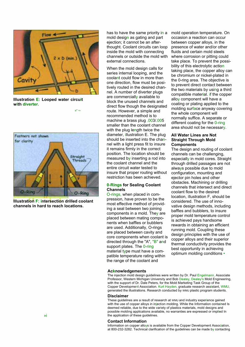
Illustration E: Looped water circuitwith diverter.
a*' •»
has to have the same priority in a mold design as gating and part ejection; it cannot be an after-thought. Coolant circuits can loop inside the mold with connectingchannels or outside the mold with external connections.
When the mold design calls for series internal looping, and the coolant could flow in more thanone direction, flow must be posi-tively routed in the desired chan-nel. A number of diverter plugsare commercially available to block the unused channels and direct flow though the designatedroute. However, a simple andrecommended method is tomachine a brass plug .003/.005smaller than the coolant channelwith the plug length twice the diameter, illustration E. The plug should be inserted into the chan-nel with a light press fit to insureit remains firmly in the correct position. The location should be measured by inserting a rod into the coolant channel and theentire circuit water tested toinsure that proper routing withoutrestriction has been achieved.
0-Rings for Sealing CoolantChannelsO-rings, when placed in com-pression, have proven to be the most effective method of provid-ing a seal between two joiningcomponents in a mold. They are placed between mating compo-nents when baffles or bubblersare used. Additionally, O-ringsare placed between cavity and core components when coolant is directed through the "A", "B" andsupport plates. The 0-ringmaterial type must have a com-patible temperature rating withinthe range of the coolant and
mold operation temperature. On occasion a reaction can occurbetween copper alloys, in the presence of water and/or other fluids and certain mold steelswhere corrosion or pitting could take place. To prevent the possi-bility of this electrolytic actiontaking place, the copper alloy can be chromium or nickel-plated in the 0-ring area. The objective is to prevent direct contact betweenthe two materials by using a thirdcompatible material. if the copperalloy component will have acoating or plating applied to the molding surface anyway coveringthe whole component will normally suffice. A separate or different coating for the 0-ringarea should not be necessary.
All Water Lines are Not Straight Through Mold ComponentsThe design and routing of coolantchannels can be challenging,especially in mold cores. Straight through drilled passages are not always possible due to moldconfiguration, mounting andejector pin holes and other obstacles. Machining or drilling channels that intersect and direct coolant flow to the desiredlocation, illustration F, should be considered. The use of inno-vative design methods, includingbaffles and bubblers, to insureproper mold temperature control is achieved pays handsomerewards in obtaining an efficientrunning mold. Coupling thesedesign principles with the use of copper alloys and their superiorthermal conductivity provides the best opportunity in achievingoptimum molding conditions •
Illustration F: intersection drilled coolant channels in hard to reach locations.
AcknowledgementsThe injection mold design guidelines were written by Dr. Paul Engelmann, Associate Professor, Western Michigan University and Bob Dealey, Dealey's Mold Engineering,with the support of Dr. Dale Peters, for the Mold Marketing Task Group of the Copper Development Association. Kurt Hayden, graduate research assistant, WMU,generated the illustrations. Research conducted by WMU plastic program students.
DisclaimerThese guidelines are a result of research at WMU and industry experience gained with the use of copper alloys in injection molding. While the Information contained Is deemed reliable, due to the wide variety of plastics materials, mold designs and possible molding applications available, no warranties are expressed or implied In the application of these guidelines. »iContact InformationInformation on copper alloys is available from the Copper Development Association,at 800-232-3282. Technical clarification of the guidelines can be made by contacting

Injection Mold DesignGuidelinesSEVENTH IN A SERIES
Maximizing Performance Using Copper Alloys
Leader Pins and Bushings(Aluminum Bronze Copper Alloys)Leader pins and bushings providethe initial alignment of the cavity andcore halves on mold closing. It ismandatory that the leader pins andbushings engage prior to any mold component entering or makingcontact with the opposite mold side.Four pins and bushings are used permold, located at the four comers of the mold base. Sufficient mold basematerial must remain aftermachining the bore to providesupport for the bushing.
Three of the leader pins andbushings are located the samedimension from the edges of the mold base. The fourth bushing isoffset at the zero-zero corner, thecorner of the mold, which will be the top right hand stationary side of themold when viewed from the partingline. The offset, insuring that the mold can not be assembled incor-rectly, is at least one-sixteenth of aninch. Offset's on larger mold bases,or when space allows, is frequentlyone-eighth of an inch.
The most effective and longestlasting combination, compared to steel bushings, mates a case hard-ened groveless leader pin withAmpco 18 or Ampco 21 aluminumbronze leader pin bushings. Overall leader
pin length should be at least the sum of the thickness of the "A" and "B" plate. The bearing length of the bushing should be two to two andone-half times the nominal diameter of the leader pin(See Illustration A) insufficient or excessive bearinglengths will result in prematurefailure. Maintain pin contact with the bushing at the parting line entrance;install the clearance at the back endof the bushing if necessary.
The normal standard "A" series moldconstruction, has the leader pinsinstalled in the "A" plate and the bushings installed in the "B" plate. Reversed pin and bushingplacement is permissible when warranted due to intentional plate movement. Installing bushings in floating plates and using the four leader pin bushings to guide the plates is standard practice in injection mold design.
Leader bushing length should be the plate thickness in which it will be inserted minus .005 to .010 inches.The counter bore for the flange should be installed .015 incheslarger than the bushing to insure that it is not making contact. The plate hole diameter should be machinednominal to .0005 inches oversize to provide for a line-to-line or .0005 interference fit. While a leader pin bushing can be installed in a hole with a greater interference, too tight of a fit will cause the internal diame-ter of the leader pin to collapse,reducing the desired clearancebetween the pin and bushing.
The diameter of the leader pin must be sufficiently large to sup-
Illustration A: Aluminum bronze leader pin bushing with flange

and cores and the moving components. When usingaluminum bronze underneathslides the wear plates shouldextend beyond the bearingarea and be retained outsidethe bearing area. The wearplate should be designedsymmetrical if possible (boltor dowel holes, cam pinclearance slots, etc.), allow-ing the plate to be inverted should chips or other debrisever mar the surface.Aluminum Bronze Slide GibsGuides, either "L" or "T"shaped are used to locateand retain moving mold members. The most commonapplication is with slides,illustration C shows aluminumbronze gibs guiding of a convention slide movement.The mold should be designedfor the slide gibs to guide the moving slide member for the full travel. Depending uponthe weight of the slide carrierand the size of the mold the slide gibs should be longenough to provide accuratealignment of the slide to the mold cavity or core. The gibmust act as a guide over theentire length of travel. They should be doweled using two solid dowels, with a clearancehole through the wear plate,to the mold base or mold component. It then should beheld in place with two or morecap screws with the headsrecessed into the gib.
The gib will serve two func-tions. The first is to preciselyguide the slide in its movement and mating withthe mold cavity and core. Toaccomplish this "Running orSliding Fits" (RC class) is typically used in the mold design. Depending on the accuracy of alignment the standard tolerance rangeusing American NationalStandard institute tables fallsbetween a
port the total weight of the mold while, unfortunately, helping to line up the molding machineplatens. Table A can be used as a guide in selecting leader pin nominal sizes.
Sizes above those normallyconsidered standard usediameters appropriate for theweight of the mold.
Aluminum Bronze Slide wearPlates
Mold movements, those not in the normal line of draw, use movingmechanisms referred to as slides,lifters, wedges, cams or sideactions. These movementsoperate better when riding on an inserted bearing surface material.Typical mold base materialsmake horrible wear surfaces. In the early days of mold building a very hard steel plate was insertedin the mold base to act as a wear surface interface. While effective in providing the hardnessdifferential between the moldbase and moving mold component, the mechanismfrequently costing $1,000 to $10,000 receives all the damage.The wear plate, with a typical costof around $100, should be used both as the bearing area and the sacrificial mold component.
Aluminum bronze wear plates,Illustration B, should be used to act as the bearing surfacebetween mold bases, cavities
Illustration B: Wear plate installed under side or moving mold member
Illustration C: Gibs made fromaluminum bronze guide slides and moving mold memebers
Recommended nominal leader pin and brushing diameter by mold basesizeWidth Mold base lengths (up to)
8 9 10 12 14 16 18 24 26 30 367 7/8 .75 .75 .75 .759 7/8 .75 .75 .75 1.00 1.0 1.00 1.0010 7/8 1.00 1.0 1.00 1.00 1.0011 7/8 1.00 1.0 1.00 1.00 1.0013 3/8 1.0 1.00 1.00 1.00 1.00 1.0014 7/8 1.25 1.25 1.25 1.25 1.25 1.2515 7/8 1.25 1.25 1.25 1.25 1.25 1.2516 1/2 1.25 1.25 1.25 1.25 1.25 1.25
17 7/8 1.25 1.2 1.25 1.25 1.2519 1/2 1.25 1.2 1.25 1.25 1.2523 3/4 1.5 1.50 1.50 1.5025 7/8 1.50 1.50 1.50TO 36 2.00Table A: Nominal diameter of bushings by mold size.

H5 and a H8 for the dimensionbetween the gibs and a g 4 to an f 7 for the slide carrier. As always,when providing clearances in injection molds the overriding factor is to insure against flash while holding the required productdimension. When those two con-siderations have been accountedfor, only then can the application of normal clearances be incorporatedto the mold to achieve the desiredcondition.
The second function is for the gib to retain the slide and keep it from derailing. Clearance up and down can be greater than side to side if the opposite mold side will hold the slide in position in molding. If no contact will be made when the mold is closed, than the slide gibs mustprovide that assistance.
Gibs have two surfaces that could be used to assist in guiding the slide carrier. Only one surfaceshould be used as the bearingguide, typically the top surface. Theother surface should be cleared anadditional .001 of an inch or more to reduce friction.
Aluminum bronze Guided Ejector System BushingsHigh-speed molds using small diameter ejector pins require sup-port for the ejector and ejectorretainer plate to insure smoothoperation. Another effective use of aluminum bronze is in the bushingsused in conjunction with grovelessleader pins installed on the ejector side of the mold. Leader pins, with nominal diameters Of .750, 1.00, 1.25, 1.50 and2.00 inches, are placed at the four corners in the ejector housing. The greater the mold length and the heavier the mold plates, the largerthe nominal diameter of the leader pin should be. (Illustration D).
Common practice is to insert the leader pin head into the supportplate. This provides a safe, handyand convenient method for the mold maker to assemble the ejector system as the ejector plates are supported in the proper position.The only disadvantage to this construction method is if the sup-port plate will have a higher rate of thermal expansion that the ejector plates. When high mold temperatedifferentials are anticipated, mountingthe leader pin heads in the ejector
housing plate reduces interferencecreated by uneven thermal expansionbetween the two components.
When manufacturing guided ejectorbushings, the shoulder is placed closerto the middle of the bushing. A counterbore is machined in the ejector plate totrap the bushing between it and theejector retainer plate. The bushingshould be designed to extend the fullthickness of both the ejector and ejectorretainer plates. The side wall of thebushing should be one-fourth of an inchto provide strength. As the guided ejector system is difficult to access inthe assembled mold, a method tolubricate from the outside of the mold isrecommend. Grease fittings intoconnecting spiral grooves machinedinto the bushing is the preferred methodof providing lubrication to the bearingsurfaces.
Illustration D: Four aluminum bronzebushings with mid-busing flange usedto guide ejector system.
Angle Interlock Face PlatesIjection mold leader pins and bushingsact as a rough alignment system,interlocks are used to provide the final and precision mating of the cavity andcore. TWO styles of interlocks are used. The first is straight interlock and its function is to line up the two moldhalves prior to the mold closing. Theseinterlocks are either mounted on the side of the mold base and are calledstraight side locks or mounted on the face of the mold at the parting line andcalled top mount interlocks. Straightinterlocks normally align the entire moldrather than individual cavities and coresand the interlocking concept and is used when alignment is necessary onmold closing. This system is mandatorywhen using vertical shut offs or tele-scoping cores.
The second style of interlocking is a tapered concept installed in the moldbase or on the cavity and core. Thisinterlocking method is used when the objective is to hold the two mold halvesin register during the mold filling andcooling stage, obviously after the mold has closed. This type of interlocking insures that the mold halfs, when closed will not shift in relationship to each other. Thenominal angle for this interlocking system is typically not less than 10 or more than 15 degrees. The female interlock is almost always on the cavity side of the mold. Placing the female interlock on the side of the mold that runs the warmestreduces the incidence of the mold not closing due to differential of thermal expansion created by the normal practice of running thecavity side of the mold warmer.Larger molds use a double taperedinterlock system where the
interlocks are machined directly into the mold base, or in mono-blockconstruction, the cavity and core blocks.
Aluminum bronze wear plates,illustration E, mounted on the face of one of the interlock serve three extremely important functions. First,they prevent galling, common whentwo similar steel interfaces would normally contact each other, due to the differential in hardness andmaterial composition whileproviding low friction char-acteristics. Next, the aluminum bronze faceplates provide an effi-cient method of fitting and adjustingduring mold construction or at mold maintenance intervals. Last, they are less expensive to replaceshould any damage to the inter-locking system occur over the life of the mold. Aluminum bronzefaceplates should be at least one quarter of an inch thick andmounted with recessed flat head screws.Friction Between MaterialsFriction has been described as the resistance to motion when onecomponent is moved upon another.it typically is defined as "that force which acts between two bodies at their surface of contact, so as to resist their sliding on each other." Every moving part in a mold must overcome friction to perform itsfunction with the least amountofferee. Therefore low coefficientsof friction are a desirable attribute. The measurement used is based on the coefficient of static friction. These values will be higher than those describing sliding friction. Two categories of fric-

Ilustration E: Wear plates used on moldinterlocks.
tion should be viewed. The firstwhen the components do nothave lubrication and the second,when lubrication is used. TableB lists static coefficient of the two materials. In additionallyusing dissimilar materials willprevent galling and transfer of the material from one component to the other. Theuse of aluminum bronze willprovide a superb bearingsurface and will be inexpensive to install and maintain. All moving parts in injection mold, with the exception of ejectorpins and ejector sleeve andcomponents making directcontact with the plastic material should use lubrication. Typically a high temperature lubricationthat will not migrate is recommended.High Wear Areas in MoldsAlthough the copper alloysAA83, AA95 and AA940 aregenerally recommended forcores in plastic forming areas of the mold, there can be applica-tions where Ampco 18 or Ampco 21 is a viable option.One such application is when lifters are used to mold slightundercuts and the mechanism is mounted on the side face of the core. The thermal conductivityrate of the material is better than that of steel, but not as good as the plastics forming alloys. The aluminum bronze, with its greatnon lubricated wear propertiesand low coefficient of friction,has been shown to be the idealmaterial for these applications.Caution should be used not to install delicate detail close toside walls, as the material doesnot have the strength of the AA83, AA95 or AA940 alloys.
Static coefficients of friction whensteel is in contact with steel oraluminum bronze
Material NotLubricated
Lubricated
Steel againststeel
0.8 0.16
Aluminumbronzeagainst steel
0.35 Notmeasurable
Table B: Static coefficient of frictionbetween mold materials.
The mounting, sliding and pivoting ends of lifters is another great application for the aluminum bronzematerials. Wear plates and guidesfor wedges and raising moldmembers all benefit from the ideal bearing surfaces provided by the Ampco 18 or Ampco 21 materials.
In addition to leader pin and guidedejector system bushings, aluminumbronze bearings are used to provide a wear surface for large diameterejector return pins and to supportknock out rods extending through the ejector housing. The material servesas an excellent guide method on racks used in unscrewing molds andmoving cams in molds.
Experience has shown that the Ampco 18 or Ampco 21 aluminumbronze copper alloy is an effectivemethod of providing an excellentround or flat bearing surface in injection molds and plastic tooling. The life of a mold is greatly extended with the application of this materialand the cost of maintenance is reduced when the lowest cost component requires replacement.

Injection Mold DesignGuidelinesEIGHTH IN A SERIES
Maximizing Performance Using Copper Alloys
Protecting copper Alloys With Plating
Frequently various coatings or platings are used in injectionmolds to prevent corrosion or erosion from the plastics attack-ing the mold. Coatings canreduce mold maintenance inter-vals while extend mold life.Copper alloys, AA83, AA95 and AA940 utilized for their highthermal conductivity
rough surface finish will improveslightly when plated and asmooth highly polished surfacewill appear less polished. The plating process will not cover scratches, nicks and surfaceimperfections. Any mold defectsmust be removed prior to plating.
While it is a common and accept-able practice to sample a moldprior to plating, it is necessary toremove all traces of plastic fromthe component and notify theplater that the mold is used. Mold drawings, indicating the moldingsurfaces to be plated, shouldaccompany the components tothe plater. Masking surfaceswhere the plating is not desiredcan and should be noted on themold drawings, if there is a goodreason for not applying plating.However, masking can be a timeconsuming and expensive opera-tion and it is normally a better choice to plate the entire compo-nent when it will not interfere withthe molding process.
Choices for Protecting CopperAlloysA wide variety of platings andcoatings are available to protectyour mold components. Some aremore effective than others andindividual choices will varydepending upon the applicationand experiences with your type of applications. Additionally the quality of a given plating or coat-ing may be very dependant uponthe company that did the work.
Based on studies taking place atWestern Michigan University twotypes of platings are showing themost promise depending upon
properties to improve part quality andreduce cycle times,are no different than tool steels whenprotection is desired.
Copper alloys in the presence of some plastic residues will react with mating steel components andcreate an electriccurrent flow, similar to a battery isolating the copper- to-steel con-tact, Illustration A, with plating eliminatesthe galvanic action between the two materials and
Illustration A: use of copper alloy in cavityfor thermal conductivity and plated to isolateit from the steel cavity.
prevents the formation of small amounts of tarnish that couldtransfer to the plastic part. Typically the insert is completely covered with the plating. Preparing Surfaces for PlatingThe desired SPl surface finish, A-1through D-3, should be applied to the copper alloy prior to shipment to the plating source. The plating will generally duplicate the surfacewhere it is applied. A very

Channels cut into mold components (for forming ribs on theplastic part) create problems in electroplating. When the depth is greater than one half the width,plating thickness will vary considerably and diminish on the sides of the walls as the depthincreases. Illustration D shows a typical condition encountered in molds. The sharp outside and inside corners, coupled with the depth of the channels preventsthe chrome from building upevenly. Illustration E exhibits a more ideal construction methodusing an insert eliminating thechannel depth-to-width problem.Additionally, the generousoutside radius eliminates the problem of excessive outsidecorner build up, while the inside radius reduces corner starvation.When mold components can not be modified to optimize theelectroplating process thenanodes have to be built to get the plating down into deep channels.
Benching of ElectroplatedMold ComponentsMold components must be benched after electroplating. Any overhanging chrome depositsmust be removed prior to sampling the mold or the plasticwill form around the build up and the results will either be stickingof the plastic part or the chrometree breaking off or chippingexposing the parent material.Illustration F shows chipping of chrome in a gate area. Twomethods are normally used to remove the chrome build up. The first is with a hard 600 grit stone and carefully stoning the surface in the direction of draw, removingany chrome build up which wouldcreate an undercut.
The second method, performedby a skilled mold maker, uses a nylon brush mounted in a rotarytool operating at a slow speedwith light pressure and a chromepolish. The surface is gentlyworked, carefully removing only the overhand so as not to destroythe intended plating thickness or reducing adhesion to the mold component. Caution has to be used, as to much pressure and/or high removal rates can causechipping and exposure of the parent material. Electroless NickelThe second category of protec-tion is electroless nickel
the specific application,chrome electroplatingand electroless nickel.The first and most effective protectionagainst wear caused by impingement of glassfilled nylon against coresis a variety of electroplated chrome platings. These chromeplatings fall into one of four categories; standardindustrial hard chrome, industrial hard chrome with its structure filled with a polymer, densi-fied chrome platings andchrome composites likeArmoloy's XADC anodular chromiumcontaining nano-composite of diamond.Chrome ElectroplatingThe electroplatingprocess uses electricalcurrent to deposit the chrome on the mold component surface. Both ferrous and non-ferrous materials con-duct current around the outside of the component and as a result the processattracts more chrome to outside sharp corners than flat surfaces.However, the copperalloys are such great electrical conductors thatcorner build up is accentuated over com-parable steel compo-nents. See Illustration B. TO reduce the build
up, sometimes referred to aschrome trees or dog bones, the use of generous outside radius isrecommended on the components outside corners.Obviously, the plastic part and its function must be able to accept the radius without detrement.Normally a generous radius,outside edge on the mold component and inside edge of the plastic part, adds greatstrength to the part and istypically a great benefit.
This electroplating process also creates problems on sharp insidecorners of the mold component,see Illustration C. A sharp corner,due to current flow, will be starved of chrome. A generous radius on the inside cornersallows for a more even build up and will prevent chipping at the corners.
Illustration B: outside corners illustrating buildup on out-side sharp corners along with thecorrect application of radii.

Illustration C: Sharp inside corners on channels withoutdraftresults in uneven plating. Draft on the walls and radii on the outside corners allow for aneven build up of crome

applied by an auto catalytic (withoutcurrent) process. The advantage of electroless nickel is that the surfaceis covered to a uniform thicknesscompared to most of the electroplating processes. As the deposition is applied uniformly and without current due to the electroless process, special draft angles are not necessary and the process is forgiving on both insideand outside corners. The disadvan-tage is that the hardness of nickel is in the 50 Re range, a lower hard-ness than many of the other plat-ings available. Additionally, nickel is not a great bearing material and it should not be used in applicationswith moving parts.Plating of Holes Electroless nickel has the advan-tage of covering side surfaces of holes or channels with large aspectratios. Sharp inside corners on blind holes are difficult to cover and a radius is recommended on any blind hole. On holes up to .125 inch in diameter the depth is limited to about .750 inch due to problemsassociated with getting the gases out of the hole. There is no practicallimit to the depth of platingelectroless nickel in holes greaterthan .125 inch on conventionalmolds. (Table 1)
Electroplating chrome into holes ismore difficult than applying nickel. Frequently, anodes have to be built to assist in the application process.The cost of constructing the anodecan be a significant additional costnot encountered with electrolessnickel. Maintaining the properposition of the anode also addsdifficulty in the plating process. Not withstanding the cost and difficulty,one plater uses the informationlisted in the following table as a guide to maximum depths ofchrome plating into blind or through holes.
Deposition ThicknessThe best thickness to apply a coating to a mold component is anage-old question and opinions differwidely. Experience and extensivetesting at Western MichiganUniversity shows that a thin layer ofprotection is extremely effective. The first consideration has to be to insure that the plating will adhere tothe patent metal. This favors a thinlayer over a thick layer. The secondconsideration is to the reason whythe plating was applied in the firstplace and if a thicker layer willprovide better protection.
Table 2 lists plating thickness,which have proven to be effective in protecting copper alloys used in plastic forming applications.
Deposition TemperaturesCare must be taken to avoidexposing all materials used in mold construction to excessive heatwhich could stress relieve or annealthe component. The copper alloys should not be exposed to temperatures above recommendedmanufacture specifications,typically around 400 degrees F.The electroless nickel process is typically less than 200 degrees F. Chrome electroplating usually has a process temperature of 185degrees F or less. PVD or CVDprocess can run up to and some-times exceed 400 degrees F.Considerations must to be given to the use of processes that exposecopper alloys to temperaturesapproaching 900 degrees F, such as those found in some titaniumnitride processes. Exposing copperalloys and some other mold alloys to high temperatures
Illustration D: illustration shows the unevenplating build resulting from typical moldconstruction practices. Chrome build up is thickon the outside corners and thin to non-existentin the channels.
for extended times can be detri-mental to their properties.
Reasons for Plating Mold ComponentsCopper alloys are plated to extendperiods between maintenance orcomponent replacement intervalsand to improve part quality. Most plating is applied to protect plasticforming components from erosionand premature failure resulting from running glass or mineral filled plastics. Testing underway at Western Michigan University, using 33% glass filled type 6 nylon in an eight cavity mold, has shown that copper alloy cores protected with some of the chrome processeshave extended component life up to 20 times longer when compared to non-plated P-20 cores.
The second reason is to protect against corrosion. The copperalloys are naturally resistant to attack from most plastics. However, to prevent tarnish and the transferof residue created by the interactionwith steel, plating of copper alloys is an effective prac-
TABLE 2.
PlatingProcess
idealThickness
MaximumThickness
ElectrolessNickel
.0005-.0007 .001
Flash Chrome .0001-.0003 .001
Thin Dense Chrome
.000050-0005
.0005
Thin Dense Chrome withDiamond
.000050-
.0005.0005
*AII dimensions are in inches
Table 1. Depth of Electroplating Chrome in HolesHolediameter
Blind Hole Through Hole
Typical Range MaximumDepth
Typical Range Maximum Depth
.125 0.00-0.75 1.00 0.00-1.50 2.00
.250 0.00-1.50 2.00 0.00-3.00 4.00
.500 0.00-6.00 8.00 0.00-12.00 16.00
.750 0.00-12.00 18.00 0.00-24.00 36.001.00 0.00-24.00 36.00 0.00-48.00 72.00*AII dimensions are in inches

tice. Nickel is recommended over chrome when molding polyvinylchloride, as hydrochloric acid will strip chrome from the componentsurface. Chrome works well with most other plastics.
Another reason for applyingplating is for wear associatedwith stripping abrasive plasticparts from cores. As chrome hasa higher hardness level, it provesto be more effective than nickel.In mold areas where componentsare in moving contact, the nodular chromes tend to workbest. The sliding coefficient of friction of non-lubricated nodularchrome against nodular chrome is around 0.14. This compares to a rating of 0.20 of steel againststeel. Nickel does not hold up as well in rubbing applications.
The last reason for plating is toimprove mold release. Nickel and chrome with impregnatedpolymers are offered by a number of companies as asolution in reducing friction and improving part release. Othercompanies offer wide ranges of platings and coatings in whichthey claim success in resolvingrelease problems. Due to the wide range of mold conditionsand plastic part design, it is difficult to qualify what processworks better. However, if is safeto say that the first priority has to be to allow adequate draft anglesand provide proper ejectionmechanisms as a first step to insure part release. Next, the mold component must be benched properly. This includesremoving all
machining marks and stoning or polishing in the direction of drawwith the proper grits, prior to applying the desired surfacefinish.
The plating should only beapplied after the plastic forming mold surfaces have the proper finish. A coating or plating will not resolve all release and ejectionproblems;especially thosecreated by improper moldfinishes.
Affect on Thermal Conductivityof Copper AlloysExtensive laboratory testing on the affect of nickel or chromeplating on thermal conductivity isscheduled by the CDA. At thistime the experience gained in running thermal studies indicatesthat there is no measurable loss in cooling effectiveness when comparing the same plated and non-plated mold cores. Similarly,no significant change in cycletime, have been reported in situa-tions where molds are sampledwithout plating and then platedand run in production. One theoryis that the high thermal conductivity of the copper alloyovercomes any reduction in heat flow from the plastic part that the thin layer of plating could create. Allowing for Plating ThicknessIn certain situations the thicknessof the plating has to be taken into account in mold design. Fits of inserts, for example, should allow for the increase in size due to plating thickness insuring propermold function. These allowancesare typically in the range of tenths to a few thousands of an inch.
Illustration E: This illustration shows a suggested method Of manufacture that results in a component that can be plated to aneven thickness
Illustration F: Chipping in gate area caused by improper removal of chrome build up at the corners

Injection Mold DesignGuidelinesThis Ninth Design Guideline will address applications of copper alloys in molds
Maximizing Performance using Copper Alloys
Injection Mold Core ApplicationsCopper alloys, specifically AA83, AA95 and AA940 continue to enhance performance, reduce cycletime and cost, and improve part quality in injection moldingapplications. The injection moldcore is responsible for removing the majority of the heat from the injected plastic and mold materialswith high thermal conductivityconsistently outperform thosematerials with low thermal con-ductivity.
Advantages of mold materials with high thermal conductivity includenot only reduction of the cooling phase of the molding process, but also contribute to dimensionalcontrol with less tolerance deviation,less part warpage, fewer molded-instresses and reduced incidence of sink marks.Copper Alloys for CycleReductionThe tremendous thermal conduc-tivity, along with their high densityand excellent tensile strength,makes copper alloys an ideal choicefor a core material. Molders are reporting between 20 and 50% reductions in the cooling portion of the molding cycle. Kodak, forexample in a recent article, reportedthat in a test mold "copper alloycores ran 18 deg F cooler than the 420 stainless steel cores." The cop-per alloys are used in both large and small molds. In large molds,(Picture A), coolant channels are machined into the core similar to ferrous materials. The higher ther-mal conductivity, up to nine timesgreater than some tool steels, con-trols the mold temperature evenlyand closer to the temperature of the circulating media.
Smaller mold cavity and cores(Picture B), where installing coolingchannels in the proper position is a common problem, benefit from the high thermal conductivity of the copper alloys. When coolant cannotbe circulated through the small mold core, channels surrounding the core provide an excellent method of extracting the heat from the plasticpart, allowing for faster cycles.
High cavitation, high-speed molds benefit from the rapid heat removalcharacteristics of the copper alloys.These fast cycling molds frequentlyrunning in single digit seconds, ben-efit greatly from the rapid transfer of heat from the molding surfacethrough small diameter cores. Due to the size of many of these moldcomponents coolant channels areimpossible to install in the normallyrecommended proximity to the molding surfaces. The high thermal conductivity of the copper alloy corestransfer heat effectively whilemaintaining even mold surface tem-peratures. Multiple small diametercore pins, (Picture C), in contact with chill plates have proven to be an extremely effective method of cooling cores in studies conducted atWestern Michigan University. While results from mold-to-mold will vary, the test mold at WMU using the chill plate cooling method, with nocoolant circulating in the cores, runsat less than a six second cycle time. This compares to 15 seconds withtool steel cores and a steel chill plate.Sink Mark ReductionSink marks on injection mold parts,resulting from the delayed solidifi-cation in heavy part sections after
Picture A:
Picture B:
Picture C:

the gate has frozen off, can bereduced by application of highthermally conductive copper alloysin strategic positions around the heavy sections. In thick wall andboss sections, coring out sectionsof plastics with copper alloy corehas proven to be an effectivemethod of both reducing the incidence of sink marks and coolingtimes.
Tighter TolerancesWhen product designs call for tightdimensional tolerances with qualitylevels demanding three or six sigmamolding, all molding parametersmust be closely held. A constantand uniform mold surfacetemperature will provide for thegreatest opportunity to produceparts with the narrowest tolerancerange. The copper alloys, with theirgreat thermal properties coupledwith good mold temperature control,provide the right combination fortolerance control in injection molds.
Injection Mold CavitiesIn situations where plastic shrinksaway from cavity surfaces, coolingconditions are less demanding andthe copper alloys are used more inapplications where "A" side coringis required. Television backs, for example, have large amounts ofdetail cored from the cavity side. inthese molds, cooling cycle timereductions of 25% have beenreported by replacing ferrous inserts with copper alloys. Entire sections of cavities have beeninserted prior to final machining andthe finished cavity detail has beenmachined in assembly reducingmold building, benching andfinishing costs.
Injection Mold SlidesCoolant channels are typicallydifficult to install in slides andmoving members of molds. Theseinternal mold actions are usually inlocations where proper cooling is paramount for the dimensionalstability and/or function of theplastic part. With the sophisticated plastic part design levels demandedfrom today's injections molds, moldsurface temperature control ismandatory in the molding process.(Picture D), shows the use of copper alloys in a four-cavity mold,where due to multiple core drawsthe part interior is formed entirely byslides. The copper alloys are idealchoices for these slides, as most of the heat from the plastic must betransferred through the alloys
to the cooling system.
Core, Sprue Puller and SuckerPinsStandard off the shelf pins madefrom AA83, AA95 or AA940(Picture E) have enjoyed hugesuccess in molds with their ability to transfer heat from the contact areato the base of the pin. A spruepuller pin made from copper alloysrapidly set the puller end of sprueand provides an excellent surfacearea to hold the sprue on theejector side of the mold.
Picture DMaterial saver core pins utilized toremove plastic and cool designatedareas are the most inexpensiveapplications of copper alloys whileperhaps providing the greatestbenefit in reducing the mold cycletime. Three plate molds, where thesucker pins must hold the gate dropfirmly to allow the gate to break,cycle faster when the plastic undercut area sets up quicker.
Cladding or Bimetal InsertsWhen the properties of both ferrousand copper alloys are required for a particular application, swaging ofcopper alloys around materials like420 SS have been used (PictureF). The swaging process insurescomplete thermal contact withoutthe worries of oxidation formingbetween the two materials.
Picture E
Blow Molds Copper alloys, AA83, AA95 andAA940 have superior corrosionresistance in the presence ofpolyvinyl chloride and is the material of choice for clear blowmolded cavities (Picture G). Againthe high thermal conductivity ratesof the copper alloys, coupled withtheir high densities, produce thebest molding cycles. Anotheradvantage is the high degree ofluster possible with the alloys. Picture F
in other applications where neck and tail pinch offs are inserted, the copper alloys are normallyspecified because of their excellenttensile and compressive strengths.These materials continue to provesuperior to aluminum in pinch off applications. Additionally blowmolds that require tight dimensionalcontrol and long mold life specifycopper alloys for their moldmaterial.
Ejector SleevesPicture GThe aluminum bronze materials,
Ampco 18, Ampco 21, with their

excel lent wear characteristics and low
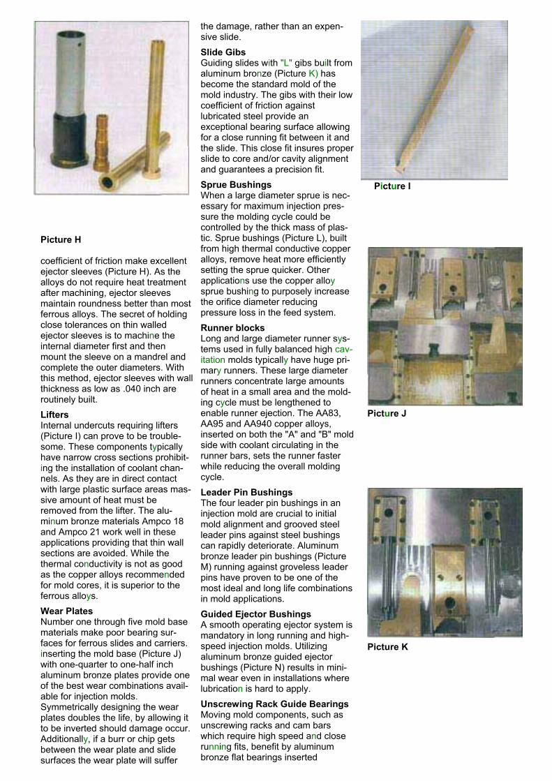
the damage, rather than an expen-sive slide.Slide GibsGuiding slides with "L" gibs built from aluminum bronze (Picture K) hasbecome the standard mold of the mold industry. The gibs with their low coefficient of friction againstlubricated steel provide anexceptional bearing surface allowingfor a close running fit between it and the slide. This close fit insures properslide to core and/or cavity alignmentand guarantees a precision fit. Sprue BushingsWhen a large diameter sprue is nec-essary for maximum injection pres-sure the molding cycle could be controlled by the thick mass of plas-tic. Sprue bushings (Picture L), built from high thermal conductive copperalloys, remove heat more efficiently setting the sprue quicker. Other applications use the copper alloysprue bushing to purposely increasethe orifice diameter reducingpressure loss in the feed system. Runner blocksLong and large diameter runner sys-tems used in fully balanced high cav-itation molds typically have huge pri-mary runners. These large diameterrunners concentrate large amountsof heat in a small area and the mold-ing cycle must be lengthened to enable runner ejection. The AA83, AA95 and AA940 copper alloys,inserted on both the "A" and "B" moldside with coolant circulating in the runner bars, sets the runner fasterwhile reducing the overall moldingcycle.Leader Pin BushingsThe four leader pin bushings in an injection mold are crucial to initial mold alignment and grooved steel leader pins against steel bushingscan rapidly deteriorate. Aluminum bronze leader pin bushings (Picture M) running against groveless leaderpins have proven to be one of the most ideal and long life combinationsin mold applications.Guided Ejector BushingsA smooth operating ejector system ismandatory in long running and high-speed injection molds. Utilizingaluminum bronze guided ejectorbushings (Picture N) results in mini-mal wear even in installations where lubrication is hard to apply.Unscrewing Rack Guide BearingsMoving mold components, such asunscrewing racks and cam bars which require high speed and closerunning fits, benefit by aluminum bronze flat bearings inserted
Picture I
Picture H
coefficient of friction make excellentejector sleeves (Picture H). As the alloys do not require heat treatmentafter machining, ejector sleevesmaintain roundness better than mostferrous alloys. The secret of holding close tolerances on thin walled ejector sleeves is to machine the internal diameter first and then mount the sleeve on a mandrel andcomplete the outer diameters. With this method, ejector sleeves with wallthickness as low as .040 inch are routinely built.LiftersInternal undercuts requiring lifters (Picture I) can prove to be trouble-some. These components typicallyhave narrow cross sections prohibit-ing the installation of coolant chan-nels. As they are in direct contact with large plastic surface areas mas-sive amount of heat must beremoved from the lifter. The alu-minum bronze materials Ampco 18and Ampco 21 work well in these applications providing that thin wall sections are avoided. While the thermal conductivity is not as goodas the copper alloys recommendedfor mold cores, it is superior to the ferrous alloys.Wear PlatesNumber one through five mold basematerials make poor bearing sur-faces for ferrous slides and carriers.inserting the mold base (Picture J)with one-quarter to one-half inch aluminum bronze plates provide one of the best wear combinations avail-able for injection molds.Symmetrically designing the wearplates doubles the life, by allowing it to be inverted should damage occur.Additionally, if a burr or chip gets between the wear plate and slide surfaces the wear plate will suffer
Picture J
Picture K

between the component and mold base. A light coating of hightemperature non-migrating lubricant will provide anexcellent low friction surface.
Runnerless Molding Systems Components
Runnerless molding systems, frequently referred to as hot runners, probes, drops and bushing divergent tips, benefit from the fast heat transfer provided by copper alloys (Picture0). Materials with high rates of thermal conductivity allow the heat source to be some distance from the tip while main-taining and controlling temperatures within a close range.The importance of maintaining uniform tip temperatures in the gate area on an RMS cannot be emphasized enough.Plating of the probe or bushing will extend component life when molding abrasive materials.
Picture L
Picture M Picture O
Picture N