ccs c compiler manual pcd - warburtech.co.uk · ccs c compiler manual ... interrupts ......
TRANSCRIPT

CCS C Compiler Manual PCD
September 2013
ALL RIGHTS RESERVED. Copyright Custom Computer Services, Inc. 2013
ii
Table of Contents Overview .................................................................................................................................... 1
Installation .............................................................................................................................. 1 Technical Support .................................................................................................................. 1 Directories .............................................................................................................................. 2 File Formats ........................................................................................................................... 2 Invoking the Command Line Compiler .................................................................................... 4 PCW Overview ....................................................................................................................... 6 Menu ...................................................................................................................................... 7 Editor Tabs ............................................................................................................................. 7 Slide Out Windows ................................................................................................................. 7 Editor ...................................................................................................................................... 7 Debugging Windows ............................................................................................................... 7 Status Bar .............................................................................................................................. 8 Output Messages ................................................................................................................... 8
Program Syntax ......................................................................................................................... 9 Overall Structure .................................................................................................................... 9 Comment ................................................................................................................................ 9 Trigraph Sequences ..............................................................................................................11 Multiple Project Files .............................................................................................................11 Multiple Compilation Units .....................................................................................................12 Example ................................................................................................................................12
Statements ................................................................................................................................13 if ............................................................................................................................................13 while ......................................................................................................................................13 do-while .................................................................................................................................14 for ..........................................................................................................................................14 switch ....................................................................................................................................15 return .....................................................................................................................................15 goto .......................................................................................................................................15 label ......................................................................................................................................16 break .....................................................................................................................................16 continue .................................................................................................................................16 expr .......................................................................................................................................17 ; .............................................................................................................................................17 stmt .......................................................................................................................................17
Expressions ..............................................................................................................................18 Operators ..............................................................................................................................18 Operator Precedence ............................................................................................................19 Reference Parameters ..........................................................................................................20 Variable Argument Lists ........................................................................................................20 Default Parameters................................................................................................................21 Overloaded Functions ...........................................................................................................21
Data Definitions .........................................................................................................................22 Basic and Special types ........................................................................................................22 Declarations ..........................................................................................................................25 Non-RAM Data Definitions .....................................................................................................26 Using Program Memory for Data ...........................................................................................27 Function Definition .................................................................................................................29

Table of Contents
iii
Functional Overview..................................................................................................................30 I2C ........................................................................................................................................30 ADC ......................................................................................................................................31 Analog Comparator ...............................................................................................................32 CAN Bus ...............................................................................................................................33 CCP1 ....................................................................................................................................35 CCP2, CCP3, CCP4, CCP5, CCP6 .......................................................................................36 Code Profile...........................................................................................................................36 Configuration Memory ...........................................................................................................37 DAC ......................................................................................................................................38 Data Eeprom .........................................................................................................................39 Data Signal Modulator ...........................................................................................................40 External Memory ...................................................................................................................41 General Purpose I/O ..............................................................................................................41 Internal LCD ..........................................................................................................................42 Internal Oscillator ..................................................................................................................43 Interrupts ...............................................................................................................................44 Low Voltage Detect ...............................................................................................................45 PMP/EPMP ...........................................................................................................................46 Power PWM ..........................................................................................................................47 Program Eeprom ...................................................................................................................48 PSP .......................................................................................................................................50 QEI ........................................................................................................................................51 RS232 I/O .............................................................................................................................52 RTOS ....................................................................................................................................54 SPI ........................................................................................................................................56 Timer0 ...................................................................................................................................57 Timer1 ...................................................................................................................................58 Timer2 ...................................................................................................................................59 Timer3 ...................................................................................................................................59 Timer4 ...................................................................................................................................59 Timer5 ...................................................................................................................................60 TimerA ...................................................................................................................................60 TimerB ...................................................................................................................................61 USB .......................................................................................................................................62 Voltage Reference .................................................................................................................65 WDT or Watch Dog Timer .....................................................................................................66 interrupt_enabled() ................................................................................................................67 Stream I/O .............................................................................................................................67
Pre-Processor ...........................................................................................................................70 PRE-PROCESSOR ...............................................................................................................70 _attribute_x ...........................................................................................................................72 #ASM #ENDASM ..................................................................................................................73 #BIT ......................................................................................................................................83 #BUILD ..................................................................................................................................84 #BYTE ...................................................................................................................................84 #CASE ..................................................................................................................................85 _DATE_ .................................................................................................................................86 #DEFINE ...............................................................................................................................86 #DEFINEDINC ......................................................................................................................87 #DEVICE ...............................................................................................................................88

PCD
iv
_DEVICE_ .............................................................................................................................90 #ERROR ...............................................................................................................................90 #EXPORT (options) ...............................................................................................................91 __FILENAME__ ....................................................................................................................92 #FILL_ROM ...........................................................................................................................93 #FUSES ................................................................................................................................93 #HEXCOMMENT ..................................................................................................................94 #ID ........................................................................................................................................94 #IF exp #ELSE #ELIF #ENDIF ..............................................................................................95 #IFDEF #IFNDEF #ELSE #ELIF #ENDIF ..............................................................................96 #IGNORE_WARNINGS .........................................................................................................97 #IMPORT (options)................................................................................................................97 #INCLUDE ............................................................................................................................98 #INLINE .................................................................................................................................99 #INT_xxxx .............................................................................................................................99 __LINE__ ............................................................................................................................ 104 #LIST .................................................................................................................................. 104 #LINE .................................................................................................................................. 104 #LOCATE ............................................................................................................................ 105 #MODULE ........................................................................................................................... 105 #NOLIST ............................................................................................................................. 106 #OCS .................................................................................................................................. 107 #OPT ................................................................................................................................... 107 #ORG .................................................................................................................................. 107 #PIN_SELECT .................................................................................................................... 109 __PCB__ ............................................................................................................................. 111 __ PCM __ .......................................................................................................................... 112 __ PCH __ ........................................................................................................................... 112 #PRAGMA ........................................................................................................................... 113 #PRIORITY ......................................................................................................................... 113 #PROFILE ........................................................................................................................... 113 #RESERVE ......................................................................................................................... 114 #ROM .................................................................................................................................. 115 #SEPARATE ....................................................................................................................... 116 #SERIALIZE ........................................................................................................................ 116 #TASK ................................................................................................................................. 118 __ TIME __ .......................................................................................................................... 119 #TYPE ................................................................................................................................. 119 #UNDEF .............................................................................................................................. 120 #USE CAPTURE ................................................................................................................. 121 #USE DELAY ...................................................................................................................... 122 #USE DYNAMIC_MEMORY ................................................................................................ 123 #USE FAST_IO ................................................................................................................... 123 #USE FIXED_IO .................................................................................................................. 124 #USE I2C ............................................................................................................................ 124 #USE PROFILE() ................................................................................................................ 126 #USE PWM ......................................................................................................................... 126 #USE RS232 ...................................................................................................................... 128 #USE RTOS ....................................................................................................................... 132 #USE SPI ............................................................................................................................ 133 #USE STANDARD_IO ......................................................................................................... 134

Table of Contents
v
#USE TIMER ....................................................................................................................... 135 #USE TOUCHPAD .............................................................................................................. 136 #WARNING ......................................................................................................................... 137 #WORD ............................................................................................................................... 138 #ZERO_RAM ...................................................................................................................... 139
Built-in Functions .................................................................................................................... 140 BUILT-IN FUNCTIONS ........................................................................................................ 140 abs( ) ................................................................................................................................... 146 sin( ) cos( ) tan( ) asin( ) acos() atan() sinh() cosh() tanh() atan2() ...................................... 146 adc_done( ) ......................................................................................................................... 147 assert( ) ............................................................................................................................... 148 atoe ..................................................................................................................................... 149 atof( ) ................................................................................................................................... 149 pin_select() .......................................................................................................................... 150 atoi( ) atol( ) atoi32( ) ........................................................................................................... 151 bit_clear( ) ........................................................................................................................... 152 bit_set( ) .............................................................................................................................. 152 bit_test( ) ............................................................................................................................. 153 brownout_enable( ).............................................................................................................. 154 bsearch( ) ............................................................................................................................ 154 calloc( ) ................................................................................................................................ 155 ceil( ) ................................................................................................................................... 156 clc1_setup_gate() clc2_setup_gate() clc3_setup_gate() clc4_setup_gate() ......................... 156 clc1_setup_input() clc2_setup_input() clc3_setup_input() clc4_setup_input() ...................... 157 clear_interrupt( ) .................................................................................................................. 158 cwg_status( ) ....................................................................................................................... 158 cwg_restart( ) ...................................................................................................................... 159 dac_write( ) ......................................................................................................................... 159 delay_cycles( ) .................................................................................................................... 160 delay_ms( ) ......................................................................................................................... 160 delay_us( ) .......................................................................................................................... 161 disable_interrupts( ) ............................................................................................................. 162 div( ) ldiv( ) .......................................................................................................................... 163 enable_interrupts( ) ............................................................................................................. 164 erase_eeprom( ) .................................................................................................................. 164 erase_program_eeprom( ) ................................................................................................... 165 exp( ) ................................................................................................................................... 165 ext_int_edge( ) .................................................................................................................... 166 fabs( ) .................................................................................................................................. 167 getc( ) getch( ) getchar( ) fgetc( ) ......................................................................................... 167 gets( ) fgets( ) ...................................................................................................................... 168 floor( ) .................................................................................................................................. 169 fmod( ) ................................................................................................................................. 170 printf( ) fprintf( ) .................................................................................................................... 170 putc( ) putchar( ) fputc( ) ...................................................................................................... 172 puts( ) fputs( ) ...................................................................................................................... 173 free( )................................................................................................................................... 173 frexp( ) ................................................................................................................................. 174 get_capture_event() ............................................................................................................ 175 get_capture_time() .............................................................................................................. 175 get_nco_accumulator( ) ....................................................................................................... 175

PCD
vi
get_nco_inc_value( ) ........................................................................................................... 176 get_ticks( ) ........................................................................................................................... 176 get_timerA( )........................................................................................................................ 177 get_timerB( )........................................................................................................................ 177 get_timerx( ) ........................................................................................................................ 178 get_tris_x( ) ......................................................................................................................... 179 getenv( ) .............................................................................................................................. 179 gets( ) fgets( ) ...................................................................................................................... 183 goto_address( ) ................................................................................................................... 184 high_speed_adc_done( ) ..................................................................................................... 184 i2c_init( ) .............................................................................................................................. 185 i2c_isr_state( ) ..................................................................................................................... 186 i2c_poll( ) ............................................................................................................................. 186 i2c_read( ) ........................................................................................................................... 187 i2c_slaveaddr( ) ................................................................................................................... 188 i2c_speed( )......................................................................................................................... 188 i2c_start( ) ........................................................................................................................... 189 i2c_stop( ) ........................................................................................................................... 190 i2c_write( ) ........................................................................................................................... 190 input( ) ................................................................................................................................. 191 input_change_x( ) ................................................................................................................ 192 input_state( ) ....................................................................................................................... 193 input_x( ) ............................................................................................................................. 194 interrupt_active( ) ................................................................................................................ 194 isalnum(char) isalpha(char) isdigit(char) islower(char) isspace(char) isupper(char) isxdigit(char) iscntrl(x) isgraph(x) isprint(x) ispunct(x) .......................................................... 195 isamong( ) ........................................................................................................................... 196 itoa( ) ................................................................................................................................... 197 jump_to_isr( ) ...................................................................................................................... 197 kbhit( ) ................................................................................................................................. 198 label_address( ) ................................................................................................................... 199 labs( ) .................................................................................................................................. 199 lcd_contrast( ) ...................................................................................................................... 200 lcd_load( ) ........................................................................................................................... 200 lcd_symbol( ) ....................................................................................................................... 201 ldexp( ) ................................................................................................................................ 202 log( ) .................................................................................................................................... 202 log10( ) ................................................................................................................................ 203 longjmp( ) ............................................................................................................................ 203 make8( ) .............................................................................................................................. 204 make16( ) ............................................................................................................................ 205 make32( ) ............................................................................................................................ 205 malloc( ) .............................................................................................................................. 206 memcpy( ) memmove( ) ...................................................................................................... 206 memset( ) ............................................................................................................................ 207 modf( ) ................................................................................................................................. 208 _mul( ) ................................................................................................................................. 208 nargs( ) ................................................................................................................................ 209 offsetof( ) offsetofbit( ) ......................................................................................................... 210 output_x( ) ........................................................................................................................... 211 output_bit( ) ......................................................................................................................... 211

Table of Contents
vii
output_drive( ) ..................................................................................................................... 212 output_float( ) ...................................................................................................................... 213 output_high( ) ...................................................................................................................... 214 output_low( )........................................................................................................................ 214 output_toggle( ) ................................................................................................................... 215 perror( ) ............................................................................................................................... 215 port_x_pullups ( ) ................................................................................................................. 216 pow( ) pwr( ) ........................................................................................................................ 217 printf( ) fprintf( ) .................................................................................................................... 217 profileout() ........................................................................................................................... 219 psp_output_full( ) psp_input_full( ) psp_overflow( ) ............................................................. 220 putc( ) putchar( ) fputc( ) ...................................................................................................... 221 putc_send( ); ....................................................................................................................... 221 fputc_send( ); ...................................................................................................................... 221 pwm_off() ............................................................................................................................ 222 pwm_on() ............................................................................................................................ 223 pwm_set_duty() ................................................................................................................... 223 pwm_set_duty_percent ....................................................................................................... 224 pwm_set_frequency ............................................................................................................ 224 qei_get_count( ) .................................................................................................................. 225 qei_set_count( ) ................................................................................................................... 225 qei_status( )......................................................................................................................... 226 qsort( ) ................................................................................................................................. 226 rand( ).................................................................................................................................. 227 rcv_buffer_bytes( )............................................................................................................... 228 rcv_buffer_full( ) .................................................................................................................. 228 read_adc( ) .......................................................................................................................... 229 read_bank( ) ........................................................................................................................ 230 read_calibration( ) ............................................................................................................... 231 read_configuration_memory( ) ............................................................................................. 231 read_eeprom( ) .................................................................................................................... 232 read_extended_ram( ) ......................................................................................................... 232 read_program_memory( ) .................................................................................................... 233 read_external_memory( ) .................................................................................................... 233 read_high_speed_adc( ) ...................................................................................................... 233 read_program_eeprom( ) .................................................................................................... 235 realloc( ) .............................................................................................................................. 235 release_io() ......................................................................................................................... 236 reset_cpu( ) ......................................................................................................................... 237 restart_cause( ) ................................................................................................................... 237 restart_wdt( ) ....................................................................................................................... 238 rotate_left( ) ......................................................................................................................... 239 rotate_right( ) ....................................................................................................................... 239 rtc_alarm_read( ) ................................................................................................................. 240 rtc_alarm_write( ) ................................................................................................................ 240 rtc_read( ) ............................................................................................................................ 241 rtc_write( ) ........................................................................................................................... 242 rtos_await( )......................................................................................................................... 242 rtos_disable( ) ...................................................................................................................... 243 rtos_enable( ) ...................................................................................................................... 243 rtos_msg_poll( ) ................................................................................................................... 244

PCD
viii
rtos_msg_read( ) ................................................................................................................. 244 rtos_msg_send( ) ................................................................................................................ 245 rtos_overrun( ) ..................................................................................................................... 245 rtos_run( ) ............................................................................................................................ 246 rtos_signal( )........................................................................................................................ 246 rtos_stats( ) ......................................................................................................................... 247 rtos_terminate( ) .................................................................................................................. 247 rtos_wait( ) .......................................................................................................................... 248 rtos_yield( ) ......................................................................................................................... 248 set_adc_channel( ) .............................................................................................................. 249 set_nco_inc_value( ) ........................................................................................................... 250 set_power_pwm_override( ) ................................................................................................ 251 set_power_pwmx_duty( ) .................................................................................................... 251 set_pwm1_duty( ) set_pwm2_duty( ) set_pwm3_duty( ) set_pwm4_duty( ) set_pwm5_duty( ) ................................................................................................................ 252 set_ticks( ) ........................................................................................................................... 253 set_timerA( ) ........................................................................................................................ 253 set_timerB( ) ........................................................................................................................ 254 set_timerx( ) ........................................................................................................................ 254 set_tris_x( ) ......................................................................................................................... 255 set_uart_speed( ) ................................................................................................................ 256 setjmp( ) .............................................................................................................................. 257 setup_adc(mode) ................................................................................................................ 257 setup_adc_ports( )............................................................................................................... 258 setup_ccp1( ) setup_ccp2( ) setup_ccp3( ) setup_ccp4( ) setup_ccp5( ) setup_ccp6( ) ....................................................................................................................... 259 setup_clc1() setup_clc2() setup_clc3() setup_clc4() ............................................................ 261 setup_comparator( ) ............................................................................................................ 261 setup_counters( ) ................................................................................................................ 262 setup_cwg( ) ........................................................................................................................ 263 setup_dac( ) ........................................................................................................................ 264 setup_external_memory( ) ................................................................................................... 265 setup_high_speed_adc( ) .................................................................................................... 265 setup_high_speed_adc_pair( ) ............................................................................................ 266 setup_lcd( ) ......................................................................................................................... 267 setup_low_volt_detect( ) ...................................................................................................... 268 setup_nco( ) ........................................................................................................................ 268 setup_opamp1( ) setup_opamp2( ) ...................................................................................... 269 setup_oscillator( ) ................................................................................................................ 269 setup_pmp(option,address_mask) ....................................................................................... 270 setup_power_pwm( ) ........................................................................................................... 271 setup_power_pwm_pins( ) ................................................................................................... 272 setup_psp(option,address_mask) ........................................................................................ 273 setup_pwm1( ) setup_pwm2( ) setup_pwm3( ) setup_pwm4( ) ............................................ 274 setup_qei( ) ......................................................................................................................... 275 setup_rtc( ) .......................................................................................................................... 275 setup_rtc_alarm( ) ............................................................................................................... 276 setup_spi( ) setup_spi2( ) .................................................................................................... 276 setup_timer_A( ) .................................................................................................................. 277 setup_timer_B( ) .................................................................................................................. 277 setup_timer_0( ) .................................................................................................................. 278

Table of Contents
ix
setup_timer_1( ) .................................................................................................................. 279 setup_timer_2( ) .................................................................................................................. 279 setup_timer_3( ) .................................................................................................................. 280 setup_timer_4( ) .................................................................................................................. 281 setup_timer_5( ) .................................................................................................................. 281 setup_uart( ) ........................................................................................................................ 282 setup_vref( ) ........................................................................................................................ 283 setup_wdt( )......................................................................................................................... 283 shift_left( ) ........................................................................................................................... 284 shift_right( ) ......................................................................................................................... 284 sleep( ) ................................................................................................................................ 285 sleep_ulpwu( ) ..................................................................................................................... 286 spi_data_is_in( ) spi_data_is_in2( ) ..................................................................................... 286 spi_init() ............................................................................................................................... 287 spi_prewrite(data); ............................................................................................................... 288 spi_read( ) spi_read2( ) ..................................................................................................... 288 spi_read_16() ...................................................................................................................... 289 spi_read2_16() .................................................................................................................... 289 spi_read3_16() .................................................................................................................... 289 spi_read4_16() .................................................................................................................... 289 spi_speed ............................................................................................................................ 290 spi_write( ) spi_write2( ) ...................................................................................................... 290 spi_xfer( ) ............................................................................................................................ 291 SPII_XFER_IN() .................................................................................................................. 292 sprintf( ) ............................................................................................................................... 292 sqrt( ) ................................................................................................................................... 293 srand( ) ................................................................................................................................ 293 STANDARD STRING FUNCTIONS( ) memchr( ) memcmp( ) strcat( ) strchr( ) strcmp( ) strcoll( ) strcspn( ) strerror( ) stricmp( ) strlen( ) strlwr( ) strncat( ) strncmp( ) strncpy( ) strpbrk( ) strrchr( ) strspn( ) strstr( ) strxfrm( ) ...................................... 294 strtod( ) ................................................................................................................................ 295 strtok( ) ................................................................................................................................ 296 strtol( ) ................................................................................................................................. 297 strtoul( ) ............................................................................................................................... 298 swap( ) ................................................................................................................................ 299 tolower( ) toupper( ) ............................................................................................................. 299 touchpad_getc( ) ................................................................................................................. 300 touchpad_hit( ) .................................................................................................................... 301 touchpad_state( ) ................................................................................................................ 301 tx_buffer_bytes() ................................................................................................................. 302 tx_buffer_full( ) .................................................................................................................... 303 va_arg( ) .............................................................................................................................. 303 va_end( ) ............................................................................................................................. 304 va_start ............................................................................................................................... 305 write_bank( )........................................................................................................................ 305 write_configuration_memory( ) ............................................................................................ 306 write_eeprom( ) ................................................................................................................... 306 write_external_memory( ) .................................................................................................... 307 write_extended_ram( ) ......................................................................................................... 308 write_program_eeprom( ) .................................................................................................... 308 write_program_memory( ) ................................................................................................... 309

PCD
x
Standard C Include Files ......................................................................................................... 311 errno.h ................................................................................................................................. 311 float.h .................................................................................................................................. 311 limits.h ................................................................................................................................. 312 locale.h ................................................................................................................................ 312 setjmp.h ............................................................................................................................... 312 stddef.h ............................................................................................................................... 313 stdio.h.................................................................................................................................. 313 stdlib.h ................................................................................................................................. 313
Error Messages ....................................................................................................................... 314 Compiler Error Messages .................................................................................................... 314
Compiler Warning Messages .................................................................................................. 323 Compiler Warning Messages ............................................................................................... 323
Common Questions & Answers .............................................................................................. 326 How are type conversions handled? .................................................................................... 326 How can a constant data table be placed in ROM? ............................................................. 327 How can I use two or more RS-232 ports on one PIC®? ..................................................... 327 How can the RB interrupt be used to detect a button press? ............................................... 328 How do I directly read/write to internal registers? ................................................................ 329 How do I do a printf to a string? ........................................................................................... 329 How do I get getc() to timeout after a specified time? .......................................................... 330 How do I make a pointer to a function? ................................................................................ 330 How do I put a NOP at location 0 for the ICD? ..................................................................... 330 How do I wait only a specified time for a button press? ....................................................... 331 How do I write variables to EEPROM that are not a byte? ................................................... 331 How does one map a variable to an I/O port? ...................................................................... 331 How does the compiler determine TRUE and FALSE on expressions? ............................... 333 How does the PIC® connect to a PC? ................................................................................. 333 How does the PIC® connect to an I2C device? ................................................................... 334 How much time do math operations take? ........................................................................... 334 Instead of 800, the compiler calls 0. Why? .......................................................................... 335 Instead of A0, the compiler is using register 20. Why? ....................................................... 335 What can be done about an OUT OF RAM error? ............................................................... 335 What is an easy way for two or more PICs® to communicate? ............................................ 336 What is an easy way for two or more PICs® to communicate? ............................................ 337 What is the format of floating point numbers? ...................................................................... 338 Why does the .LST file look out of order? ............................................................................ 339 Why does the compiler show less RAM than there really is? ............................................... 339 Why does the compiler use the obsolete TRIS? .................................................................. 340 Why is the RS-232 not working right? .................................................................................. 340
Example Programs ................................................................................................................. 343 EXAMPLE PROGRAMS ...................................................................................................... 343
Software License Agreement .................................................................................................. 367 SOFTWARE LICENSE AGREEMENT..................................... Error! Bookmark not defined.
1
OVERVIEW
Installation
Insert the CD ROM, select each of the programs you wish to install and follow the on-screen instructions. If the CD does not auto start run the setup program in the root directory. For help answering the version questions see the "Directories" Help topic. Key Questions that may come up:
Keep Settings- Unless you are having trouble select this Link Compiler Extensions- If you select this the file extensions like .c will start the compiler IDE when you double click on files with that extension. .hex files start the CCSLOAD program. This selection can be change in the IDE. Install MP LAB Plug In- If you plan to use MPLAB and you don't select this you will need to download and manually install the Plug-In. Install ICD2, ICD3...drivers-select if you use these microchip ICD units. Delete Demo Files- Always a good idea Install WIN8 APP- Allows you to start the IDE from the WIN8 Start Menu.
Technical Support
Compiler, software, and driver updates are available to download at: http://www.ccsinfo.com/download Compilers come with 30 or 60 days of download rights with the initial purchase. One year maintenance plans may be purchased for access to updates as released. The intent of new releases is to provide up-to-date support with greater ease of use and minimal, if any, transition difficulty. To ensure any problem that may occur is corrected quickly and diligently, it is recommended to send an email to: [email protected] or use the Technical Support Wizard in PCW. Include the version of the compiler, an outline of the problem and attach any files with the email request. CCS strives to answer technical support timely and thoroughly. Technical Support is available by phone during business hours for urgent needs or if email responses are not adequate. Please call 262-522-6500 x32.

PCD
2
Directories
The compiler will search the following directories for Include files. Directories listed on the command line Directories specified in the .CCSPJT file The same directory as the source.directories in the ccsc.ini file
By default, the compiler files are put in C:\Program Files\PICC and the example programs are in \PICC\EXAMPLES. The include files are in PICC\drivers. The device header files are in PICC\devices. The compiler itself is a DLL file. The DLL files are in a DLL directory by default in \PICC\DLL. It is sometimes helpful to maintain multiple compiler versions. For example, a project was tested with a specific version, but newer projects use a newer version. When installing the compiler you are prompted for what version to keep on the PC. IDE users can change versions using Help>about and clicking "other versions." Command Line users use start>all programs>PIC-C>compiler version. Two directories are used outside the PICC tree. Both can be reached with start>all programs>PIC-C.
1.) A project directory as a default location for your projects. By default put in "My Documents." This is a good place for VISTA and up. 2.) User configuration settings and PCWH loaded files are kept in %APPDATA%\PICC
File Formats
.c This is the source file containing user C source code.
.h These are standard or custom header files used to define pins, register, register bits, functions and preprocessor directives.
.pjt This is the older pre- Version 5 project file which contains information related to the project.
.ccspjt This is the project file which contains information related to the project.
.lst
This is the listing file which shows each C source line and the associated assembly code generated for that line. The elements in the .LST file may be selected in PCW under Options>Project>Output Files
CCS Basic Standard assembly instructions
with Opcodes Includes the HEX opcode for each instruction
Old Standard
Symbolic Shows variable names instead of addresses
.sym This is the symbol map which shows each register location and what program variables
Overview
3
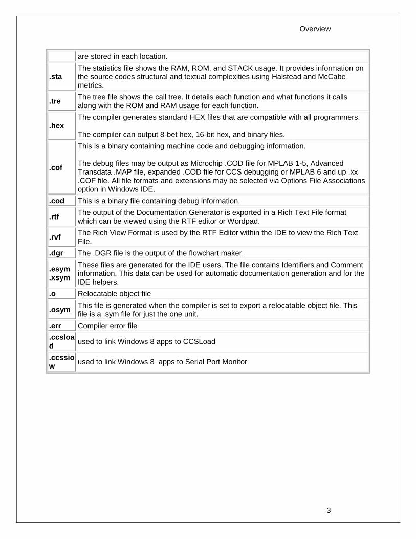
are stored in each location.
.sta The statistics file shows the RAM, ROM, and STACK usage. It provides information on the source codes structural and textual complexities using Halstead and McCabe metrics.
.tre The tree file shows the call tree. It details each function and what functions it calls along with the ROM and RAM usage for each function.
.hex The compiler generates standard HEX files that are compatible with all programmers. The compiler can output 8-bet hex, 16-bit hex, and binary files.
.cof
This is a binary containing machine code and debugging information. The debug files may be output as Microchip .COD file for MPLAB 1-5, Advanced Transdata .MAP file, expanded .COD file for CCS debugging or MPLAB 6 and up .xx .COF file. All file formats and extensions may be selected via Options File Associations option in Windows IDE.
.cod This is a binary file containing debug information.
.rtf The output of the Documentation Generator is exported in a Rich Text File format which can be viewed using the RTF editor or Wordpad.
.rvf The Rich View Format is used by the RTF Editor within the IDE to view the Rich Text File.
.dgr The .DGR file is the output of the flowchart maker.
.esym
.xsym
These files are generated for the IDE users. The file contains Identifiers and Comment information. This data can be used for automatic documentation generation and for the IDE helpers.
.o Relocatable object file
.osym This file is generated when the compiler is set to export a relocatable object file. This file is a .sym file for just the one unit.
.err Compiler error file
.ccsload
used to link Windows 8 apps to CCSLoad
.ccssiow
used to link Windows 8 apps to Serial Port Monitor

PCD
4
Invoking the Command Line Compiler
The command line compiler is invoked with the following command: CCSC [options] [cfilename]
Valid options:
+FB Select PCB (12 bit) -D Do not create debug file
+FM Select PCM (14 bit) +DS Standard .COD format debug file
+FH Select PCH (PIC18XXX) +DM .MAP format debug file
+Yx Optimization level x (0-9) +DC Expanded .COD format debug file
+DF Enables the output of an COFF debug file.
+FS Select SXC (SX) +EO Old error file format
+ES Standard error file -T Do not generate a tree file
+T Create call tree (.TRE) -A Do not create stats file (.STA)
+A Create stats file (.STA) -EW Suppress warnings (use with +EA)
+EW Show warning messages -E Only show first error
+EA Show all error messages and all warnings
+EX Error/warning message format uses GCC's "brief format" (compatible with GCC editor environments)
The xxx in the following are optional. If included it sets the file extension:
+LNxxx Normal list file +O8xxx 8-bit Intel HEX output file
+LSxxx MPASM format list file +OWxxx 16-bit Intel HEX output file
+LOxxx Old MPASM list file +OBxxx Binary output file
+LYxxx Symbolic list file -O Do not create object file
-L Do not create list file
+P Keep compile status window up after compile
+Pxx Keep status window up for xx seconds after compile
+PN Keep status window up only if there are no errors
+PE Keep status window up only if there are errors
+Z Keep scratch files on disk after compile
+DF COFF Debug file
I+="..." Same as I="..." Except the path list is appended to the current list
I="..." Set include directory search path, for example: I="c:\picc\examples;c:\picc\myincludes" If no I= appears on the command line the .PJT file will be used to supply the include file paths.

Overview
5
-P Close compile window after compile is complete
+M Generate a symbol file (.SYM)
-M Do not create symbol file
+J Create a project file (.PJT)
-J Do not create PJT file
+ICD Compile for use with an ICD
#xxx="yyy" Set a global #define for id xxx with a value of yyy, example: #debug="true"
+Gxxx="yyy" Same as #xxx="yyy"
+? Brings up a help file
-? Same as +?
+STDOUT Outputs errors to STDOUT (for use with third party editors)
+SETUP Install CCSC into MPLAB (no compile is done)
sourceline= Allows a source line to be injected at the start of the source file. Example: CCSC +FM myfile.c sourceline=“#include <16F887.h>”
+V Show compiler version (no compile is done)
+Q Show all valid devices in database (no compile is done)
A / character may be used in place of a + character. The default options are as follows: +FM +ES +J +DC +Y9 -T -A +M +LNlst +O8hex -P -Z If @filename appears on the CCSC command line, command line options will be read from the specified file. Parameters may appear on multiple lines in the file. If the file CCSC.INI exists in the same directory as CCSC.EXE, then command line parameters are read from that file before they are processed on the command line. Examples: CCSC +FM C:\PICSTUFF\TEST.C
CCSC +FM +P +T TEST.C

PCD
6
PCW Overview
The PCW IDE provides the user an easy to use editor and environment for developing microcontroller applications. The IDE comprises of many components, which are summarized below. For more information and details, use the Help>PCW in the compiler.. Many of these windows can be re-arranged and docked into different positions.
Overview
7
Menu
All of the IDE's functions are on the main menu. The main menu is divided into separate sections, click on a section title ('Edit', 'Search', etc) to change the section. Double clicking on the section, or clicking on the chevron on the right, will cause the menu to minimize and take less space.
Editor Tabs
All of the open files are listed here. The active file, which is the file currently being edited, is given a different highlight than the other files. Clicking on the X on the right closes the active file. Right clicking on a tab gives a menu of useful actions for that file. )
Slide Out Windows
'Files' shows all the active files in the current project. 'Projects' shows all the recent projects worked on. 'Identifiers' shows all the variables, definitions, prototypes and identifiers in your current project.
Editor
The editor is the main work area of the IDE and the place where the user enters and edits source code. Right clicking in this area gives a menu of useful actions for the code being edited.
Debugging Windows
Debugger control is done in the debugging windows. These windows allow you set breakpoints, single step, watch variables and more.

PCD
8
Status Bar
The status bar gives the user helpful information like the cursor position, project open and file being edited.
Output Messages
Output messages are displayed here. This includes messages from the compiler during a build, messages from the programmer tool during programming or the results from find and searching.

9
PROGRAM SYNTAX
Overall Structure
A program is made up of the following four elements in a file: Comment Pre-Processor Directive Data Definition Function Definition Every C program must contain a main function which is the starting point of the program execution. The program can be split into multiple functions according to the their purpose and the functions could be called from main or the sub-functions. In a large project functions can also be placed in different C files or header files that can be included in the main C file to group the related functions by their category. CCS C also requires to include the appropriate device file using #include directive to include the device specific functionality. There are also some preprocessor directives like #fuses to specify the fuses for the chip and #use delay to specify the clock speed. The functions contain the data declarations,definitions,statements and expressions. The compiler also provides a large number of standard C libraries as well as other device drivers that can be included and used in the programs. CCS also provides a large number of built-in functions to access the various peripherals included in the PIC microcontroller.
Comment
Comments – Standard Comments A comment may appear anywhere within a file except within a quoted string. Characters between /* and */ are ignored. Characters after a // up to the end of the line are ignored. Comments for Documentation Generator The compiler recognizes comments in the source code based on certain markups. The compiler recognizes these special types of comments that can be later exported for use in the documentation generator. The documentation generator utility uses a user selectable template to export these comments and create a formatted output document in Rich Text File Format. This utility is only available in the IDE version of the compiler. The source code markups are as follows. Global Comments These are named comments that appear at the top of your source code. The comment names are case sensitive and they must match the case used in the documentation template. For example: //*PURPOSE This program implements a Bootloader. //*AUTHOR John Doe

PCD
10
A '//' followed by an * will tell the compiler that the keyword which follows it will be the named comment. The actual comment that follows it will be exported as a paragraph to the documentation generator. Multiple line comments can be specified by adding a : after the *, so the compiler will not concatenate the comments that follow. For example: /**:CHANGES 05/16/06 Added PWM loop 05/27.06 Fixed Flashing problem */ Variable Comments A variable comment is a comment that appears immediately after a variable declaration. For example: int seconds; // Number of seconds since last entry long day, // Current day of the month, /* Current Month */ long year; // Year Function Comments A function comment is a comment that appears just before a function declaration. For example: // The following function initializes outputs void function_foo() {
init_outputs(); } Function Named Comments The named comments can be used for functions in a similar manner to the Global Comments. These comments appear before the function, and the names are exported as-is to the documentation generator. For example: //*PURPOSE This function displays data in BCD format void display_BCD( byte n) {
display_routine(); }
Program Syntax
11
Trigraph Sequences
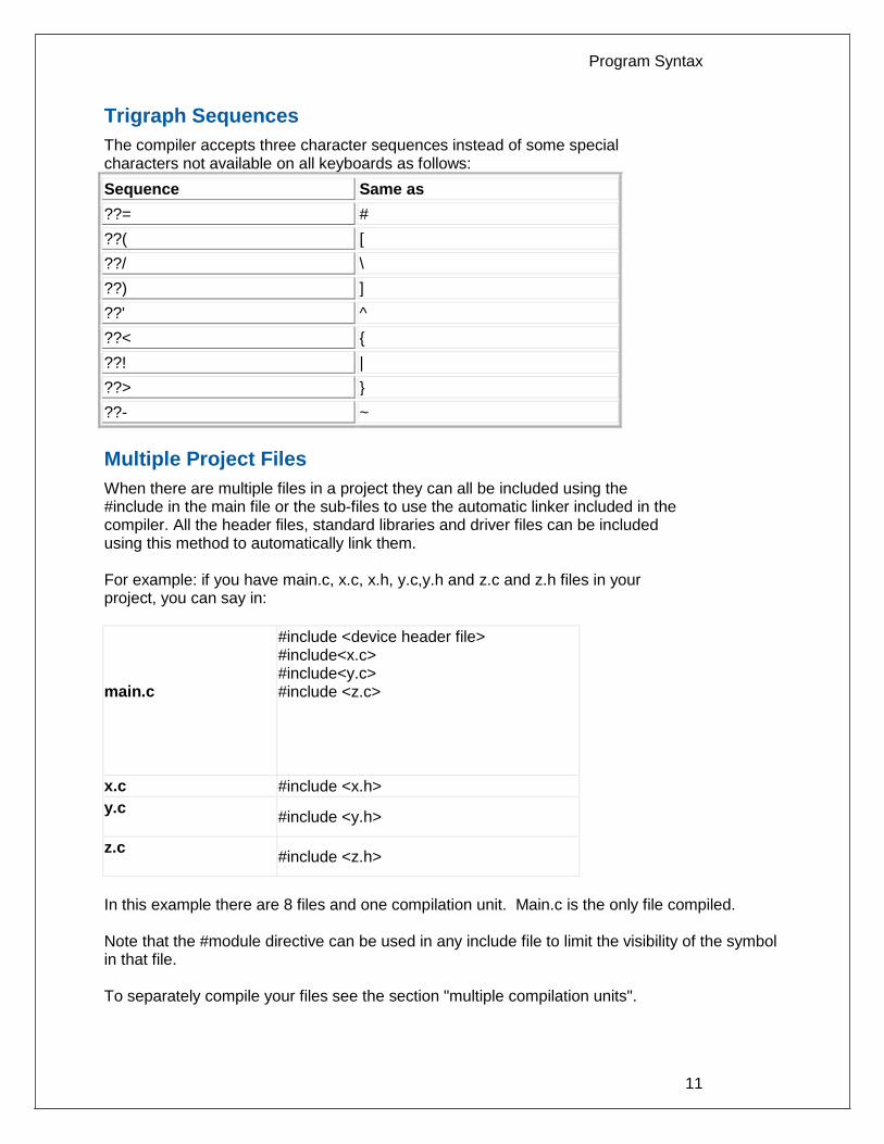
The compiler accepts three character sequences instead of some special characters not available on all keyboards as follows:
Sequence Same as
??= #
??( [
??/ \
??) ]
??' ^
??< {
??! |
??> }
??- ~
Multiple Project Files
When there are multiple files in a project they can all be included using the #include in the main file or the sub-files to use the automatic linker included in the compiler. All the header files, standard libraries and driver files can be included using this method to automatically link them. For example: if you have main.c, x.c, x.h, y.c,y.h and z.c and z.h files in your project, you can say in:
main.c
#include <device header file> #include<x.c> #include<y.c> #include <z.c>
x.c #include <x.h>
y.c
#include <y.h>
z.c
#include <z.h>
In this example there are 8 files and one compilation unit. Main.c is the only file compiled. Note that the #module directive can be used in any include file to limit the visibility of the symbol in that file. To separately compile your files see the section "multiple compilation units".

PCD
12
Multiple Compilation Units
Traditionally, the CCS C compiler used only one compilation unit and multiple files were implemented with #include files. When using multiple compilation units, care must be given that pre-processor commands that control the compilation are compatible across all units. It is recommended that directives such as #FUSES, #USE and the device header file all put in an include file included by all units. When a unit is compiled it will output a relocatable object file (*.o) and symbol file (*.osym). There are several ways to accomplish this with the CCS C Compiler. All of these methods and example projects are included in the MCU.zip in the examples directory of the compiler.
Example
Here is a sample program with explanation using CCS C to read adc samples over rs232: ///////////////////////////////////////////////////////
/// This program displays the min and max of 30, ///
/// comments that explains what the program does, ///
/// and A/D samples over the RS-232 interface. ///
///////////////////////////////////////////////////////
#include <16F887.h> // preprocessor directive that selects the chip
PIC16F887
#fuses NOPROTECT // Code protection turned off
#use delay(crystal=20mhz) // preprocessor directive that specifies the clock
type and speed
#use rs232(baud=9600, xmit=PIN_C6, rcv=PIN_C7) // preprocessor directive that
includes the
// rs232 libraries
void main() { // main function
int i, value, min, max; // local variable declaration
printf("Sampling:"); // printf function included in
the RS232 library
setup_port_a( ALL_ANALOG ); // A/D setup functions- built-
in
setup_adc( ADC_CLOCK_INTERNAL ); // Internal clock always works
set_adc_channel( 0 ); // Set channel to AN0
do { // do forever statement
min=255;
max=0;
for(i=0; i<=30; ++i) { // Take 30 samples
delay_ms(100); // Wait for a tenth of a
second
value = Read_ADC(); // A/D read functions- built-
in
if(value<min) // Find smallest sample
min=value;
if(value>max) // Find largest sample
max=value;
}
printf("\n\rMin: %2X Max: %2X\n\r",min,max);
} while (TRUE);
}

13
STATEMENTS
if
if-else The if-else statement is used to make decisions. The syntax is: if (expr) stmt-1; [else stmt-2;] The expression is evaluated; if it is true stmt-1 is done. If it is false then stmt-2 is done. else-if This is used to make multi-way decisions. The syntax is: if (expr) stmt; [else if (expr) stmt;] ... [else stmt;] The expressions are evaluated in order; if any expression is true, the statement associated with it is executed and it terminates the chain. If none of the conditions are satisfied the last else part is executed. Example: if (x==25)
x=1;
else
x=x+1;
Also See: Statements
while
While is used as a loop/iteration statement. The syntax is:

PCD
14
while (expr) statement The expression is evaluated and the statement is executed until it becomes false in which case the execution continues after the statement. Example: while (get_rtcc()!=0)
putc('n');
Also See: Statements
do-while
do-while: Differs from while and for loop in that the termination condition is checked at the bottom of the loop rather than at the top and so the body of the loop is always executed at least once. The syntax is: do statement while (expr); The statement is executed; the expr is evaluated. If true, the same is repeated and when it becomes false the loop terminates. Also See: Statements , While
for
For is also used as a loop/iteration statement. The syntax is: for (expr1;expr2;expr3) statement The expressions are loop control statements. expr1 is the initialization, expr2 is the termination check and expr3 is re-initialization. Any of them can be omitted. Example: for (i=1;i<=10;++i)
printf("%u\r\n",i);
Also See: Statements

Statements
15
switch
Switch is also a special multi-way decision maker. The syntax is switch (expr) { case const1: stmt sequence; break; ... [default:stmt] } This tests whether the expression matches one of the constant values and branches accordingly. If none of the cases are satisfied the default case is executed. The break causes an immediate exit, otherwise control falls through to the next case. Example: switch (cmd) {
case 0:printf("cmd 0");
break;
case 1:printf("cmd 1");
break;
default:printf("bad cmd");
break; }
Also See: Statements
return
return A return statement allows an immediate exit from a switch or a loop or function and also returns a value. The syntax is: return(expr); Example: return (5);
Also See: Statements
goto
goto The goto statement cause an unconditional branch to the label. The syntax is: goto label;

PCD
16
A label has the same form as a variable name, and is followed by a colon. The goto's are used sparingly, if at all. Example: goto loop;
Also See: Statements
label
label The label a goto jumps to. The syntax is: label: stmnt; Example: loop: i++;
Also See: Statements
break
break. The break statement is used to exit out of a control loop. It provides an early exit from while, for ,do and switch. The syntax is break; It causes the innermost enclosing loop (or switch) to be exited immediately. Example: break;
Also See: Statements
continue
The continue statement causes the next iteration of the enclosing loop(While, For, Do) to begin. The syntax is:

Statements
17
continue; It causes the test part to be executed immediately in case of do and while and the control passes the re-initialization step in case of for. Example: continue;
Also See: Statements
expr
The syntax is: expr; Example: i=1;
Also See: Statements
;
Statement: ; Example: ;
Also See: Statements
stmt
Zero or more semi-colon separated. The syntax is: {[stmt]} Example: {a=1;
b=1;}
Also See: Statements

18
EXPRESSIONS
Operators
+ Addition Operator
+= Addition assignment operator, x+=y, is the same as x=x+y
&= Bitwise and assignment operator, x&=y, is the same as x=x&y
& Address operator
& Bitwise and operator
^= Bitwise exclusive or assignment operator, x^=y, is the same as x=x^y
^ Bitwise exclusive or operator
l= Bitwise inclusive or assignment operator, xl=y, is the same as x=xly
l Bitwise inclusive or operator
?: Conditional Expression operator
- - Decrement
/= Division assignment operator, x/=y, is the same as x=x/y
/ Division operator
== Equality
> Greater than operator
>= Greater than or equal to operator
++ Increment
* Indirection operator
!= Inequality
<<= Left shift assignment operator, x<<=y, is the same as x=x<<y
< Less than operator
<< Left Shift operator
<= Less than or equal to operator
&& Logical AND operator
! Logical negation operator
ll Logical OR operator
%= Modules assignment operator x%=y, is the same as x=x%y
% Modules operator
*= Multiplication assignment operator, x*=y, is the same as x=x*y
* Multiplication operator

Data Definitions
19
~ One's complement operator
>>= Right shift assignment, x>>=y, is the same as x=x>>y
>> Right shift operator
-> Structure Pointer operation
-= Subtraction assignment operator, x-=y, is the same as x=x- y
- Subtraction operator
sizeof Determines size in bytes of operand
Operator Precedence
PIN DESCENDING PRECEDENCE
(expr)
++expr expr++ - -expr expr - -
!expr ~expr +expr -expr
(type)expr *expr &value sizeof(type)
expr*expr expr/expr expr%expr
expr+expr expr-expr
expr<<expr expr>>expr
expr<expr expr<=expr expr>expr expr>=expr
expr==expr expr!=expr
expr&expr
expr^expr
expr | expr
expr&& expr
expr || expr
expr ? expr: expr
lvalue = expr lvalue+=expr lvalue-=expr
lvalue*=expr lvalue/=expr lvalue%=expr
lvalue>>=expr lvalue<<=expr lvalue&=expr
lvalue^=expr lvalue|=expr
expr, expr
(Operators on the same line are equal in precedence)

PCD
20
Reference Parameters
The compiler has limited support for reference parameters. This increases the readability of code and the efficiency of some inline procedures. The following two procedures are the same. The one with reference parameters will be implemented with greater efficiency when it is inline.
funct_a(int*x,int*y){
/*Traditional*/
if(*x!=5)
*y=*x+3;
}
funct_a(&a,&b);
funct_b(int&x,int&y){
/*Reference params*/
if(x!=5)
y=x+3;
}
funct_b(a,b);
Variable Argument Lists
The compiler supports a variable number of parameters. This works like the ANSI requirements except that it does not require at least one fixed parameter as ANSI does. The function can be passed any number of variables and any data types. The access functions are VA_START, VA_ARG, and VA_END. To view the number of arguments passed, the NARGS function can be used.
/*
stdarg.h holds the macros and va_list data type needed for variable
number of parameters.
*/
#include <stdarg.h>
A function with variable number of parameters requires two things. First, it requires the ellipsis (...), which must be the last parameter of the function. The ellipsis represents the variable argument list. Second, it requires one more variable before the ellipsis (...). Usually you will use this variable as a method for determining how many variables have been pushed onto the ellipsis. Here is a function that calculates and returns the sum of all variables:
int Sum(int count, ...)
{
//a pointer to the argument list
va_list al;
int x, sum=0;
//start the argument list
//count is the first variable before the ellipsis

Data Definitions
21
va_start(al, count);
while(count--) {
//get an int from the list
x = var_arg(al, int);
sum += x;
}
//stop using the list
va_end(al);
return(sum);
}
Some examples of using this new function: x=Sum(5, 10, 20, 30, 40, 50);
y=Sum(3, a, b, c);
Default Parameters
Default parameters allows a function to have default values if nothing is passed to it when called.
int mygetc(char *c, int n=100){
}
This function waits n milliseconds for a character over RS232. If a character is received, it saves it to the pointer c and returns TRUE. If there was a timeout it returns FALSE.
//gets a char, waits 100ms for timeout
mygetc(&c);
//gets a char, waits 200ms for a timeout
mygetc(&c, 200);
Overloaded Functions
Overloaded functions allow the user to have multiple functions with the same name, but they must accept different parameters. The return types must remain the same. Here is an example of function overloading: Two functions have the same name but differ in the types of parameters. The compiler determines which data type is being passed as a parameter and calls the proper function.
This function finds the square root of a long integer variable.
long FindSquareRoot(long n){
}
This function finds the square root of a float variable.
float FindSquareRoot(float n){
}
FindSquareRoot is now called. If variable is of long type, it will call the first FindSquareRoot() example. If variable is of float type, it will call the second FindSquareRoot() example.
result=FindSquareRoot(variable);

PCD
22
DATA DEFINITIONS
Basic and Special types
This section describes what the basic data types and specifiers are and how variables can be declared using those types. In C all the variables should be declared before they are used. They can be defined inside a function (local) or outside all functions (global). This will affect the visibility and life of the variables. Basic Types
Range
Type-Specifier Size Unsigned Signed Digits
int1 1 bit number 0 to 1 N/A
1/2
int8 8 bit number 0 to 255 -128 to 127
2-3
int16 16 bit number 0 to 65535 -32768 to 32767
4-5
int32 32 bit number 0 to 4294967295 -2147483648 to 2147483647
9-10
int48 48 bit number 0 to 281474976710655
-140737488355328 to 140737488355327
14-15
int64 64 bit number N/A -9223372036854775808 to 9223372036854775807
18-19
float32
32 bit float -1.5 x 1045 to 3.4 x 1038 7-8
C Standard Type Default Type
short int1
char unsigned int8
int int8
long int16
long long int32
float float32
double N/A
Type-Qualifier
static Variable is globally active and initialized to 0. Only accessible from this compilation unit.
auto Variable exists only while the procedure is active. This is the default and AUTO need not be used.
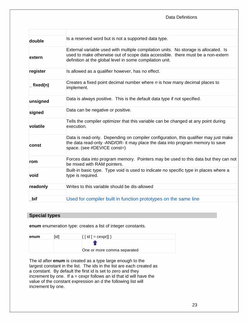
Data Definitions
23
double Is a reserved word but is not a supported data type.
extern
External variable used with multiple compilation units. No storage is allocated. Is used to make otherwise out of scope data accessible. there must be a non-extern definition at the global level in some compilation unit.
register
Is allowed as a qualifier however, has no effect.
_ fixed(n)
Creates a fixed point decimal number where n is how many decimal places to implement.
unsigned Data is always positive. This is the default data type if not specified.
signed Data can be negative or positive.
volatile Tells the compiler optimizer that this variable can be changed at any point during execution.
const
Data is read-only. Depending on compiler configuration, this qualifier may just make the data read-only -AND/OR- it may place the data into program memory to save space. (see #DEVICE const=)
rom Forces data into program memory. Pointers may be used to this data but they can not be mixed with RAM pointers.
void Built-in basic type. Type void is used to indicate no specific type in places where a type is required.
readonly Writes to this variable should be dis-allowed
_bif Used for compiler built in function prototypes on the same line
Special types enum enumeration type: creates a list of integer constants.
enum [id] { [ id [ = cexpr]] }
One or more comma separated
The id after enum is created as a type large enough to the largest constant in the list. The ids in the list are each created as a constant. By default the first id is set to zero and they increment by one. If a = cexpr follows an id that id will have the value of the constant expression an d the following list will increment by one.

PCD
24
For example: enum colors{red, green=2, blue}; // red will be 0, green will be 2 and
// blue will be 3
Struct structure type: creates a collection of one or more variables, possibly of different types, grouped together as a single unit.
struct[*] [id] {
type-qualifier [*] id [:bits]; } [id]
One or more, semi-colon separated
Zero or more
For example: struct data_record {
int a[2];
int b : 2; /*2 bits */
int c : 3; /*3 bits*/
int d;
} data_var; //data_record is a structure type
//data _var is a variable
Union type: holds objects of different types and sizes, with the compiler keeping track of size and alignment requirements. They provide a way to manipulate different kinds of data in a single area of storage.
union[*] [id] { type-qualifier [*] id [:bits]; } [id]
One or more, semi-colon separated
Zero or more
For example: union u_tab {
int ival;
long lval;
float fval;
}; // u_tag is a union type that can hold a float

Data Definitions
25
If typedef is used with any of the basic or special types it creates a new type name that can be used in declarations. The identifier does not allocate space but rather may be used as a type specifier in other data definitions.
typedef [type-qualifier] [type-specifier] [declarator];
For example: typedef int mybyte; // mybyte can be used in
declaration to
// specify the int type
typedef short mybit; // mybyte can be used in
declaration to
// specify the int type
typedef enum {red, green=2,blue}colors; //colors can be used to
declare
//variables of this enum type
__ADDRESS__: A predefined symbol __ADDRESS__ may be used to indicate a type that must hold a program memory address.
For example: ___ADDRESS__ testa = 0x1000 //will allocate 16 bits for test a and
//initialize to 0x1000
Declarations
A declaration specifies a type qualifier and a type specifier, and is followed by a list of one or more variables of that type. For example:
int a,b,c,d;
mybit e,f;
mybyte g[3][2];
char *h;
colors j;
struct data_record data[10];
static int i;
extern long j;
Variables can also be declared along with the definitions of the special types. For example:
enum colors{red, green=2,blue}i,j,k; // colors is the enum type and
i,j,k
//are variables of that type

PCD
26
Non-RAM Data Definitions
CCS C compiler also provides a custom qualifier addressmod which can be used to define a memory region that can be RAM, program eeprom, data eeprom or external memory. Addressmod replaces the older typemod (with a different syntax). The usage is : addressmod
(name,read_function,write_function,start_address,end_address,
share);
Where the read_function and write_function should be blank for RAM, or for other memory should be the following prototype: // read procedure for reading n bytes from the memory starting at
location addr
void read_function(int32 addr,int8 *ram, int nbytes){
}
//write procedure for writing n bytes to the memory starting at
location addr
void write_function(int32 addr,int8 *ram, int nbytes){
}
For RAM the share argument may be true if unused RAM in this area can be used by the compiler for standard variables.
Example: void DataEE_Read(int32 addr, int8 * ram, int bytes) {
int i;
for(i=0;i<bytes;i++,ram++,addr++)
*ram=read_eeprom(addr);
}
void DataEE_Write(int32 addr, int8 * ram, int bytes) {
int i;
for(i=0;i<bytes;i++,ram++,addr++)
write_eeprom(addr,*ram);
}
addressmod (DataEE,DataEE_read,DataEE_write,5,0xff);
// would define a region called DataEE between
// 0x5 and 0xff in the chip data EEprom.
void main (void)
{
int DataEE test;
int x,y;
x=12;
test=x; // writes x to the Data EEPROM
y=test; // Reads the Data EEPROM
}
Note: If the area is defined in RAM then read and write functions are not required, the variables assigned in the memory region defined by the addressmod can be treated as a regular variable in all valid expressions. Any structure or data type can be used with an addressmod. Pointers

Data Definitions
27
can also be made to an addressmod data type. The #type directive can be used to make this memory region as default for variable allocations. The syntax is : #type default=addressmodname // all the variable declarations
that
// follow will use this memory
region
#type default= // goes back to the default mode
For example: Type default=emi //emi is the addressmod name
defined
char buffer[8192];
#include <memoryhog.h>
#type default=
Using Program Memory for Data
CCS C Compiler provides a few different ways to use program memory for data. The different ways are discussed below: Constant Data: The const qualifier will place the variables into program memory. If the keyword const is used before the identifier, the identifier is treated as a constant. Constants should be initialized and may not be changed at run-time. This is an easy way to create lookup tables. The rom Qualifier puts data in program memory with 3 bytes per instruction space. The address used for ROM data is not a physical address but rather a true byte address. The & operator can be used on ROM variables however the address is logical not physical.
The syntax is: const type id[cexpr] = {value}
For example: Placing data into ROM
const int table[16]={0,1,2...15}
Placing a string into ROM const char cstring[6]={"hello"}
Creating pointers to constants const char *cptr;
cptr = string;
The #org preprocessor can be used to place the constant to specified address blocks.
For example: The constant ID will be at 1C00.
#ORG 0x1C00, 0x1C0F
CONST CHAR ID[10]= {"123456789"};
Note: Some extra code will precede the 123456789.
The function label_address can be used to get the address of the constant. The constant variable can be accessed in the code. This is a great way of storing constant data in large programs. Variable length constant strings can be stored into program memory. A special method allows the use of pointers to ROM. This method does not contain extra code at the start of the structure as does constant.
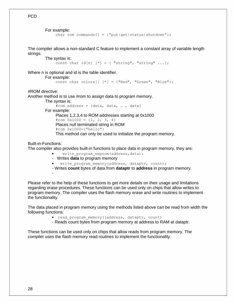
PCD
28
For example: char rom commands[] = {“put|get|status|shutdown”};
The compiler allows a non-standard C feature to implement a constant array of variable length strings.
The syntax is: const char id[n] [*] = { "string", "string" ...};
Where n is optional and id is the table identifier.
For example: const char colors[] [*] = {"Red", "Green", "Blue"};
#ROM directive: Another method is to use #rom to assign data to program memory.
The syntax is: #rom address = {data, data, … , data}
For example: Places 1,2,3,4 to ROM addresses starting at 0x1000 #rom 0x1000 = {1, 2, 3, 4}
Places null terminated string in ROM #rom 0x1000={"hello"}
This method can only be used to initialize the program memory. Built-in-Functions: The compiler also provides built-in functions to place data in program memory, they are:
write_program_eeprom(address,data);
- Writes data to program memory write_program_memory(address, dataptr, count);
- Writes count bytes of data from dataptr to address in program memory. -
Please refer to the help of these functions to get more details on their usage and limitations regarding erase procedures. These functions can be used only on chips that allow writes to program memory. The compiler uses the flash memory erase and write routines to implement the functionality. The data placed in program memory using the methods listed above can be read from width the following functions:
read_program_memory((address, dataptr, count)
- Reads count bytes from program memory at address to RAM at dataptr. These functions can be used only on chips that allow reads from program memory. The compiler uses the flash memory read routines to implement the functionality.

Data Definitions
29
Function Definition
The format of a function definition is as follows:
[qualifier] id ( [type-specifier id] ) { [stmt] }
Optional See Below
Zero or more comma separated. See Data Types
Zero or more Semi-colon separated. See Statements.
The qualifiers for a function are as follows:
VOID
type-specifier
#separate
#inline
#int_.. When one of the above are used and the function has a prototype (forward declaration of the function before it is defined) you must include the qualifier on both the prototype and function definition. A (non-standard) feature has been added to the compiler to help get around the problems created by the fact that pointers cannot be created to constant strings. A function that has one CHAR parameter will accept a constant string where it is called. The compiler will generate a loop that will call the function once for each character in the string. Example:
void lcd_putc(char c ) {
...
}
lcd_putc ("Hi There.");

30
FUNCTIONAL OVERVIEW
I2C
I2C™ is a popular two-wire communication protocol developed by Phillips. Many PIC microcontrollers support hardware-based I2C™. CCS offers support for the hardware-based I2C™ and a software-based master I2C™ device. (For more information on the hardware-based I2C module, please consult the datasheet for you target device; not all PICs support I2C™.)
Relevant Functions:
i2c_start() Issues a start command when in the I2C master mode.
i2c_write(data) Sends a single byte over the I2C interface.
i2c_read() Reads a byte over the I2C interface.
i2c_stop() Issues a stop command when in the I2C master mode.
i2c_poll() Returns a TRUE if the hardware has received a byte in the buffer.
Relevant Preprocessor:
#USE I2C Configures the compiler to support I2C™ to your specifications.
Relevant Interrupts:
#INT_SSP I2C or SPI activity
#INT_BUSCOL Bus Collision
#INT_I2C I2C Interrupt (Only on 14000)
#INT_BUSCOL2 Bus Collision (Only supported on some PIC18's)
#INT_SSP2 I2C or SPI activity (Only supported on some PIC18's)
Relevant Include Files:
None, all functions built-in
Relevant getenv() Parameters:
I2C_SLAVE Returns a 1 if the device has I2C slave H/W
I2C_MASTER Returns a 1 if the device has a I2C master H/W
Example Code:
#define Device_SDA PIN_C3 // Pin defines
#define Device_SLC PIN_C4
#use i2c(master, sda=Device_SDA, scl=Device_SCL)
// Configure Device as Master
..
..

Functional Overview
31
BYTE data; // Data to be transmitted
i2c_start(); // Issues a start command when in the I2C master mode.
i2c_write(data); // Sends a single byte over the I2C interface.
i2c_stop(); // Issues a stop command when in the I2C master mode.
ADC
These options let the user configure and use the analog to digital converter module. They are only available on devices with the ADC hardware. The options for the functions and directives vary depending on the chip and are listed in the device header file. On some devices there are two independent ADC modules, for these chips the second module is configured using secondary ADC setup functions (Ex. setup_ADC2).
Relevant Functions:
setup_adc(mode) Sets up the a/d mode like off, the adc clock etc.
setup_adc_ports(value) Sets the available adc pins to be analog or digital.
set_adc_channel(channel) Specifies the channel to be use for the a/d call.
read_adc(mode) Starts the conversion and reads the value. The mode can also control the functionality.
adc_done() Returns 1 if the ADC module has finished its conversion.
Relevant Preprocessor:
#DEVICE ADC=xx Configures the read_adc return size. For example, using a PIC with a 10 bit A/D you can use 8 or 10 for xx- 8 will return the most significant byte, 10 will return the full A/D reading of 10 bits.
Relevant Interrupts:
INT_AD Interrupt fires when a/d conversion is complete
INT_ADOF Interrupt fires when a/d conversion has timed out
Relevant Include Files:
None, all functions built-in
Relevant getenv() parameters:
ADC_CHANNELS Number of A/D channels
ADC_RESOLUTION Number of bits returned by read_adc
Example Code:
#DEVICE ADC=10
...
long value;
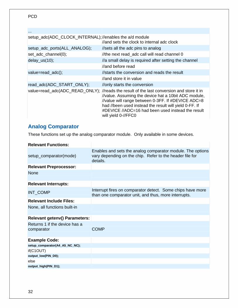
PCD
32
...
setup_adc(ADC_CLOCK_INTERNAL); //enables the a/d module //and sets the clock to internal adc clock
setup_adc_ports(ALL_ANALOG); //sets all the adc pins to analog
set_adc_channel(0); //the next read_adc call will read channel 0
delay_us(10); //a small delay is required after setting the channel
//and before read
value=read_adc(); //starts the conversion and reads the result
//and store it in value
read_adc(ADC_START_ONLY); //only starts the conversion
value=read_adc(ADC_READ_ONLY); //reads the result of the last conversion and store it in //value. Assuming the device hat a 10bit ADC module, //value will range between 0-3FF. If #DEVICE ADC=8 had //been used instead the result will yield 0-FF. If #DEVICE //ADC=16 had been used instead the result will yield 0-//FFC0
Analog Comparator
These functions set up the analog comparator module. Only available in some devices.
Relevant Functions:
setup_comparator(mode) Enables and sets the analog comparator module. The options vary depending on the chip. Refer to the header file for details.
Relevant Preprocessor:
None
Relevant Interrupts:
INT_COMP Interrupt fires on comparator detect. Some chips have more than one comparator unit, and thus, more interrupts.
Relevant Include Files:
None, all functions built-in
Relevant getenv() Parameters:
Returns 1 if the device has a comparator
COMP
Example Code: setup_comparator(A4_A5_NC_NC);
if(C1OUT)
output_low(PIN_D0);
else
output_high(PIN_D1);

Functional Overview
33
CAN Bus
These functions allow easy access to the Controller Area Network (CAN) features included with the MCP2515 CAN interface chip and the PIC18 MCU. These functions will only work with the MCP2515 CAN interface chip and PIC microcontroller units containing either a CAN or an ECAN module. Some functions are only available for the ECAN module and are specified by the work ECAN at the end of the description. The listed interrupts are no available to the MCP2515 interface chip.
Relevant Functions:
can_init(void);
Initializes the CAN module and clears all the filters and masks so that all messages can be received from any ID.
can_set_baud(void);
Initializes the baud rate of the CAN bus to125kHz, if using a 20 MHz clock and the default CAN-BRG defines, it is called inside the can_init() function so there is no need to call it.
can_set_mode (CAN_OP_MODE mode);
Allows the mode of the CAN module to be changed to configuration mode, listen mode, loop back mode, disabled mode, or normal mode.
can_set_functional_mode (CAN_FUN_OP_MODE mode);
Allows the functional mode of ECAN modules to be changed to legacy mode, enhanced legacy mode, or first in firstout (fifo) mode. ECAN
can_set_id(int* addr, int32 id, int1 ext);
Can be used to set the filter and mask ID's to the value specified by addr. It is also used to set the ID of the message to be sent.
can_get_id(int * addr, int1 ext); Returns the ID of a received message.
can_putd (int32 id, int * data, int len, int priority, int1 ext, int1 rtr);
Constructs a CAN packet using the given arguments and places it in one of the available transmit buffers.
can_getd (int32 & id, int * data, int & len, struct rx_stat & stat);
Retrieves a received message from one of the CAN buffers and stores the relevant data in the referenced function parameters.
can_enable_rtr(PROG_BUFFER b);
Enables the automatic response feature which automatically sends a user created packet when a specified ID is received. ECAN
can_disable_rtr(PROG_BUFFER b); Disables the automatic response feature. ECAN
can_load_rtr (PROG_BUFFER b, int * data, int len);
Creates and loads the packet that will automatically transmitted when the triggering ID is received.

PCD
34
ECAN
can_enable_filter(long filter);
Enables one of the extra filters included in the ECAN module. ECAN
can_disable_filter(long filter); Disables one of the extra filters included in the ECAN module. ECAN
can_associate_filter_to_buffer (CAN_FILTER_ASSOCIATION_BUFFERS buffer,CAN_FILTER_ASSOCIATION filter);
Used to associate a filter to a specific buffer. This allows only specific buffers to be filtered and is available in the ECAN module. ECAN
can_associate_filter_to_mask (CAN_MASK_FILTER_ASSOCIATE mask, CAN_FILTER_ASSOCIATION filter);
Used to associate a mask to a specific buffer. This allows only specific buffer to have this mask applied. This feature is available in the ECAN module. ECAN
can_fifo_getd(int32 & id,int * data, int &len,struct rx_stat & stat);
Retrieves the next buffer in the fifo buffer. Only available in the ECON module while operating in fifo mode. ECAN
Relevant Preprocessor:
None
Relevant Interrupts:
#int_canirx This interrupt is triggered when an invalid packet is received on the CAN.
#int_canwake This interrupt is triggered when the PIC is woken up by activity on the CAN.
#int_canerr This interrupt is triggered when there is an error in the CAN module.
#int_cantx0 This interrupt is triggered when transmission from buffer 0 has completed.
#int_cantx1 This interrupt is triggered when transmission from buffer 1 has completed.
#int_cantx2 This interrupt is triggered when transmission from buffer 2 has completed.
#int_canrx0 This interrupt is triggered when a message is received in buffer 0.
#int_canrx1 This interrupt is triggered when a message is received in buffer 1.
Relevant Include Files:
can-mcp2510.c Drivers for the MCP2510 and MCP2515 interface chips
can-18xxx8.c Drivers for the built in CAN module

Functional Overview
35
can-18F4580.c
Drivers for the build in ECAN module
Relevant getenv() Parameters:
none
Example Code:
can_init(); // initializes the CAN bus
can_putd(0x300,data,8,3,TRUE,FALSE); // places a message on the CAN buss with
// ID = 0x300 and eight bytes of data pointed to by
// “data”, the TRUE creates an extended ID, the
// FALSE creates
can_getd(ID,data,len,stat); // retrieves a message from the CAN bus storing the
// ID in the ID variable, the data at the array pointed to by
// “data', the number of data bytes in len, and statistics
// about the data in the stat structure.
CCP1
These options lets to configure and use the CCP module. There might be multiple CCP modules for a device. These functions are only available on devices with CCP hardware. They operate in 3 modes: capture, compare and PWM. The source in capture/compare mode can be timer1 or timer3 and in PWM can be timer2 or timer4. The options available are different for different devices and are listed in the device header file. In capture mode the value of the timer is copied to the CCP_X register when the input pin event occurs. In compare mode it will trigger an action when timer and CCP_x values are equal and in PWM mode it will generate a square wave.
Relevant Functions:
setup_ccp1(mode) Sets the mode to capture, compare or PWM. For capture
set_pwm1_duty(value) The value is written to the pwm1 to set the duty.
Relevant Preprocessor:
None
Relevant Interrupts :
INT_CCP1 Interrupt fires when capture or compare on CCP1
Relevant Include Files:
None, all functions built-in
Relevant getenv() parameters:

PCD
36
CCP1 Returns 1 if the device has CCP1
Example Code:
#int_ccp1
void isr()
{
rise = CCP_1; //CCP_1 is the time the pulse went high
fall = CCP_2; //CCP_2 is the time the pulse went low
pulse_width = fall - rise; //pulse width
}
..
setup_ccp1(CCP_CAPTURE_RE); // Configure CCP1 to capture rise
setup_ccp2(CCP_CAPTURE_FE); // Configure CCP2 to capture fall
setup_timer_1(T1_INTERNAL); // Start timer 1
Some chips also have fuses which allows to multiplex the ccp/pwm on different pins. So check the fuses to see which pin is set by default. Also fuses to enable/disable pwm outputs.
CCP2, CCP3, CCP4, CCP5, CCP6
Similar to CCP1
Code Profile
Profile a program while it is running. Unlike in-circuit debugging, this tool grabs information while the program is running and provides statistics, logging and tracing of it's execution. This is accomplished by using a simple communication method between the processor and the ICD with minimal side-effects to the timing and execution of the program. Another benefit of code profile versus in-circuit debugging is that a program written with profile support enabled will run correctly even if there is no ICD connected. In order to use Code Profiling, several functions and pre-processor statements need to be included in the project being compiled and profiled. Doing this adds the proper code profile run-time support on the microcontroller. See the help file in the Code Profile tool for more help and usage examples.
Relevant Functions:
profileout()
Send a user specified message or variable to be displayed or logged by the code profile tool.
Relevant Pre-Processor:
#use profile()
Global configuration of the code profile run-time on the microcontroller.
#profile Dynamically enable/disable specific elements of the profiler.

Functional Overview
37
Relevant Interrupts:
The profiler can be configured to use a microcontroller's internal timer for more accurate timing of events over the clock on the PC. This timer is configured using the #profile pre-processor command.
Relevant Include Files:
None – all the functions are built into the compiler.
Relevant getenv():
None
Example Code:
#include <18F4520.h> #use delay(crystal=10MHz, clock=40MHz) #profile functions, parameters void main(void) { int adc; setup_adc(ADC_CLOCK_INTERNAL); set_adc_channel(0); for(;;) { adc = read_adc(); profileout(adc); delay_ms(250); } }
Configuration Memory
On all PIC18 Family of chips, the configuration memory is readable and writable. This functionality is not available on the PIC16 Family of devices..
Relevant Functions:
write_configuration_memory (ramaddress, count)
Writes count bytes, no erase needed
or
write_configuration_memory (offset,ramaddress, count)
Writes count bytes, no erase needed starting at byte address offset
read_configuration_memory (ramaddress,count)
Read count bytes of configuration memory
Relevant Preprocessor:
None
Relevant Include Files:

PCD
38
None, all functions built-in
Relevant getenv() parameters:
None
Example Code:
For PIC18f452
int16 data=0xc32;
...
write_configuration_memory(data,2); //writes 2 bytes to the configuration memory
DAC
These options let the user configure and use the digital to analog converter module. They are only available on devices with the DAC hardware. The options for the functions and directives vary depending on the chip and are listed in the device header file.
Relevant Functions:
setup_dac(divisor) Sets up the DAC e.g. Reference voltages
dac_write(value) Writes the 8-bit value to the DAC module
Sets up the d/a mode e.g. Right enable, clock divisor
Writes the 16-bit value to the specified channel
Relevant Preprocessor:
#USE DELAY(clock=20M, Aux: crystal=6M, clock=3M)
Relevant Interrupts:
None
Relevant Include Files:
None, all functions built-in
Relevant getenv() parameters:
None
int8 i=0;
setup_dac (DAC_VSS_VDD);

Functional Overview
39
while (TRUE) {
itt;
dac_write(i);
}
Data Eeprom
The data eeprom memory is readable and writable in some chips. These options lets the user read and write to the data eeprom memory. These functions are only available in flash chips.
Relevant Functions:
(8 bit or 16 bit depending on the device)
read_eeprom(address) Reads the data EEPROM memory location
write_eeprom(address, value) Erases and writes value to data EEPROM location address.
Reads N bytes of data EEPROM starting at memory location address. The maximum return size is int64.
Reads from EEPROM to fill variable starting at address
Reads N bytes, starting at address, to pointer
Writes value to EEPROM address
Writes N bytes to address from pointer
Relevant Preprocessor:
#ROM address={list}
Can also be used to put data EEPROM memory data into the hex file.
write_eeprom = noint Allows interrupts to occur while the write_eeprom() operations is polling the done bit to check if the write operations has completed. Can be used as long as no EEPROM operations are performed during an ISR.
Relevant Interrupts:
INT_EEPROM Interrupt fires when EEPROM write is complete
Relevant Include Files:
None, all functions built-in
Relevant getenv() parameters:
DATA_EEPROM Size of data EEPROM memory.
Example Code:
For 18F452 #rom 0xf00000={1,2,3,4,5}
//inserts this data into the hex file. The data eeprom address //differs for different family of chips. Please refer to the //programming specs to find the right value for the device

PCD
40
write_eeprom(0x0,0x12); //writes 0x12 to data eeprom location 0
value=read_eeprom(0x0); //reads data eeprom location 0x0 returns 0x12
#ROM 0x007FFC00={1,2,3,4,5} // Inserts this data into the hex file
// The data EEPROM address differs between PICs // Please refer to the device editor for device specific values.
write_eeprom(0x10, 0x1337); // Writes 0x1337 to data EEPROM location 10.
value=read_eeprom(0x0); // Reads data EEPROM location 10 returns 0x1337.
Data Signal Modulator
The Data Signal Modulator (DSM) allows the user to mix a digital data stream (the “modulator signal”) with a carrier signal to produce a modulated output. Both the carrier and the modulator signals are supplied to the DSM module, either internally from the output of a peripheral, or externally through an input pin. The modulated output signal is generated by performing a logical AND operation of both the carrier and modulator signals and then it is provided to the MDOUT pin. Using this method, the DSM can generate the following types of key modulation schemes:
Frequency Shift Keying (FSK) Phase Shift Keying (PSK) On-Off Keying (OOK)
Relevant Functions:
(8 bit or 16 bit depending on the device)
setup_dsm(mode,source,carrier)
Configures the DSM module and selects the source signal and carrier signals.
setup_dsm(TRUE)
Enables the DSM module.
setup_dsm(FALSE)
Disables the DSM module.
Relevant Preprocessor: None
Relevant Interrupts: None
Relevant Include Files: None, all functions built-in
Relevant getenv() parameters: None

Functional Overview
41
Example Code:
setup_dsm(DSM_ENABLED | //Enables DSM module with the output enabled and selects UART1
DSM_OUTPUT_ENABLED, //as the source signal and VSS as the high carrier signal and OC1's
DSM_SOURCE_UART1, //PWM output as the low carrier signal.
DSM_CARRIER_HIGH_VSS |
DSM_CARRIER_LOW_OC1);
if(input(PIN_B0)) setup_dsm(FALSE);
Disable DSM module
else setup_dsm(TRUE);
Enable DSM module
External Memory
Some PIC18 devices have the external memory functionality where the external memory can be mapped to external memory devices like (Flash, EPROM or RAM). These functions are available only on devices that support external memory bus.
General Purpose I/O
These options let the user configure and use the I/O pins on the device. These functions will affect the pins that are listed in the device header file.
Relevant Functions:
output_high(pin) Sets the given pin to high state.
output_low(pin) Sets the given pin to the ground state.
output_float(pin) Sets the specified pin to the output mode. This will allow the pin to float high to represent a high on an open collector type of connection.
output_x(value) Outputs an entire byte to the port.
output_bit(pin,value) Outputs the specified value (0,1) to the specified I/O pin.
input(pin) The function returns the state of the indicated pin.
input_state(pin) This function reads the level of a pin without changing the direction of the pin as INPUT() does.
set_tris_x(value)
Sets the value of the I/O port direction register. A '1' is an input and '0' is for output.
input_change_x( ) This function reads the levels of the pins on the port, and compares them to the last time they were read to see if there was a change, 1 if there was, 0 if there wasn't.
Relevant Preprocessor:
#USE STANDARD_IO(port) This compiler will use this directive be default and it will automatically inserts code for the direction register whenever an I/O function like output_high() or input() is used.

PCD
42
#USE FAST_IO(port) This directive will configure the I/O port to use the fast method of performing I/O. The user will be responsible for setting the port direction register using the set_tris_x() function.
#USE FIXED_IO (port_outputs=;in,pin?)
This directive set particular pins to be used an input or output, and the compiler will perform this setup every time this pin is used.
Relevant Interrupts:
None
Relevant Include Files:
None, all functions built-in
Relevant getenv() parameters:
PIN:pb
Returns a 1 if bit b on port p is on this part
Example Code: #use fast_io(b)
...
Int8 Tris_value= 0x0F;
int1 Pin_value;
...
set_tris_b(Tris_value); //Sets B0:B3 as input and B4:B7 as output
output_high(PIN_B7); //Set the pin B7 to High
If(input(PIN_B0)){ //Read the value on pin B0, set B7 to low if pin B0 is high
output_high(PIN_B7);}
Internal LCD
Some families of PIC microcontrollers can drive a glass segment LCD directly, without the need of an LCD controller. For example, the PIC16C92X, PIC16F91X, and PIC16F193X series of chips have an internal LCD driver module.
Relevant Functions:
setup_lcd (mode, prescale, [segments])
Configures the LCD Driver Module to use the specified mode, timer prescaler, and segments. For more information on valid modes and settings, see the setup_lcd( ) manual page and the *.h header file for the PIC micro-controller being used.
lcd_symbol (symbol, segment_b7 ... segment_b0)
The specified symbol is placed on the desired segments, where segment_b7 to segment_b0 represent SEGXX pins on the PIC micro-controller. For example, if bit 0 of symbol is set, then segment_b0 is set, and if segment_b0 is 15, then SEG15 would be set.

Functional Overview
43
lcd_load(ptr, offset, length) Writes length bytes of data from pointer directly to the LCD segment memory, starting with offset.
lcd_contrast (contrast) Passing a value of 0 – 7 will change the contrast of the LCD segments, 0 being the minimum, 7 being the maximum.
Relevant Preprocessor:
None
Relevant Interrupts:
#int_lcd LCD frame is complete, all pixels displayed
Relevant Inlcude Files: None, all functions built-in to the compiler.
Relevant getenv() Parameters:
LCD Returns TRUE if the device has an Internal LCD Driver Module.
Example Program:
// How each segment of the LCD is set (on or off) for the ASCII digits 0 to 9.
byte CONST DIGIT_MAP[10] = {0xFC, 0x60, 0xDA, 0xF2, 0x66, 0xB6, 0xBE, 0xE0, 0xFE, 0xE6};
// Define the segment information for the first digit of the LCD
#define DIGIT1 COM1+20, COM1+18, COM2+18, COM3+20, COM2+28, COM1+28, COM2+20, COM3+18
// Displays the digits 0 to 9 on the first digit of the LCD.
for(i = 0; i <= 9; i++) {
lcd_symbol( DIGIT_MAP[i], DIGIT1 );
delay_ms( 1000 );
}
Internal Oscillator
Many chips have internal oscillator. There are different ways to configure the internal oscillator. Some chips have a constant 4 Mhz factory calibrated internal oscillator. The value is stored in some location (mostly the highest program memory) and the compiler moves it to the osccal register on startup. The programmers save and restore this value but if this is lost they need to be programmed before the oscillator is functioning properly. Some chips have factory calibrated internal oscillator that offers software selectable frequency range(from 31Kz to 8 Mhz) and they have a default value and can be switched to a higher/lower value in software. They are also software tunable. Some chips also provide the PLL option for the internal oscillator.
Relevant Functions:
setup_oscillator(mode, finetune)
Sets the value of the internal oscillator and also tunes it. The options vary depending on the chip and are listed in the device header files.

PCD
44
Relevant Preprocessor:
None
Relevant Interrupts:
INT_OSC_FAIL or INT_OSCF Interrupt fires when the system oscillator fails and the processor switches to the internal oscillator.
Relevant Include Files:
None, all functions built-in
Relevant getenv() parameters:
None
Example Code:
For PIC18F8722
setup_oscillator(OSC_32MHZ); //sets the internal oscillator to 32MHz (PLL enabled)
If the internal oscillator fuse option are specified in the #fuses and a valid clock is specified in the #use delay(clock=xxx) directive the compiler automatically sets up the oscillator. The #use delay statements should be used to tell the compiler about the oscillator speed.
Interrupts
The following functions allow for the control of the interrupt subsystem of the microcontroller. With these functions, interrupts can be enabled, disabled, and cleared. With the preprocessor directives, a default function can be called for any interrupt that does not have an associated ISR, and a global function can replace the compiler generated interrupt dispatcher.
Relevant Functions:
disable_interrupts() Disables the specified interrupt.
enable_interrupts() Enables the specified interrupt.
ext_int_edge() Enables the edge on which the edge interrupt should trigger. This can be either rising or falling edge.
clear_interrupt() This function will clear the specified interrupt flag. This can be used if a global isr is used, or to prevent an interrupt from being serviced.
interrupt_active() This function checks the interrupt flag of specified interrupt and returns true if flag is set.
interrupt_enabled() This function checks the interrupt enable flag of the specified interrupt and returns TRUE if set.
Relevant Preprocessor:
#DEVICE HIGH_INTS= This directive tells the compiler to generate code for high priority

Functional Overview
45
interrupts.
#INT_XXX fast This directive tells the compiler that the specified interrupt should be treated as a high priority interrupt.
Relevant Interrupts:
#int_default This directive specifies that the following function should be called if an interrupt is triggered but no routine is associated with that interrupt.
#int_global This directive specifies that the following function should be called whenever an interrupt is triggered. This function will replace the compiler generated interrupt dispatcher.
#int_xxx This directive specifies that the following function should be called whenever the xxx interrupt is triggered. If the compiler generated interrupt dispatcher is used, the compiler will take care of clearing the interrupt flag bits.
Relevant Include Files: none, all functions built in.
Relevant getenv() Parameters: none
Example Code:
#int_timer0
void timer0interrupt() // #int_timer associates the following function with the
// interrupt service routine that should be called
enable_interrupts(TIMER0); // enables the timer0 interrupt
disable_interrtups(TIMER0); // disables the timer0 interrupt
clear_interrupt(TIMER0); // clears the timer0 interrupt flag
Low Voltage Detect
These functions configure the high/low voltage detect module. Functions available on the chips that have the low voltage detect hardware.
Relevant Functions:
setup_low_volt_detect(mode) Sets the voltage trigger levels and also the mode (below or above in case of the high/low voltage detect module). The options vary depending on the chip and are listed in the device header files.
Relevant Preprocessor:

PCD
46
None
Relevant Interrupts :
INT_LOWVOLT Interrupt fires on low voltage detect
Relevant Include Files:
None, all functions built-in
Relevant getenv() parameters:
None
Example Code:
For PIC18F8722
setup_low_volt_detect (LVD_36|LVD_TRIGGER_ABOVE);
//sets the trigger level as 3.6 volts and
// trigger direction as above. The interrupt
//if enabled is fired when the voltage is
//above 3.6 volts.
PMP/EPMP
The Parallel Master Port (PMP)/Enhanced Parallel Master Port (EPMP) is a parallel 8-bit/16-bit I/O module specifically designed to communicate with a wide variety of parallel devices. Key features of the PMP module are:
· 8 or 16 Data lines · Up to 16 or 32 Programmable Address Lines · Up to 2 Chip Select Lines · Programmable Strobe option · Address Auto-Increment/Auto-Decrement · Programmable Address/Data Multiplexing · Programmable Polarity on Control Signals · Legacy Parallel Slave(PSP) Support · Enhanced Parallel Slave Port Support · Programmable Wait States
Relevant Functions: This will setup the PMP/EPMP module for various mode and
specifies which address lines to be used.
setup_psp (options,address_mask)
This will setup the PSP module for various mode and specifies which address lines to be used.
setup_pmp_csx(options,[offset]) Sets up the Chip Select X Configuration, Mode and Base Address registers
setup_psp_es(options) Sets up the Chip Select X Configuration and Mode registers Write the data byte to the next buffer location.
This will write a byte of data to the next buffer location or will

Functional Overview
47
write a byte to the specified buffer location. Reads a byte of data.
psp_read() will read a byte of data from the next buffer location and psp_read ( address ) will read the buffer location address.
Configures the address register of the PMP module with the destination address during Master mode operation.
This will return the status of the output buffer underflow bit. This will return the status of the input buffers.
psp_input_full() This will return the status of the input buffers. This will return the status of the output buffers.
psp_output_full() This will return the status of the output buffers.
Relevant Preprocessor:
None
Relevant Interrupts :
#INT_PMP Interrupt on read or write strobe
Relevant Include Files:
None, all functions built-in
Relevant getenv() parameters:
None
Example Code:
setup_pmp( PAR_ENABLE | Sets up Master mode with address lines PMA0:PMA7
PAR_MASTER_MODE_1 |
PAR_STOP_IN_IDLE,0x00FF );
If ( pmp_output_full ( ))
{
pmp_write(next_byte);
}
Power PWM
These options lets the user configure the Pulse Width Modulation (PWM) pins. They are only available on devices equipped with PWM. The options for these functions vary depending on the chip and are listed in the device header file.
Relevant Functions:
setup_power_pwm(config) Sets up the PWM clock, period, dead time etc.

PCD
48
setup_power_pwm_pins(module x) Configure the pins of the PWM to be in
Complimentary, ON or OFF mode.
set_power_pwmx_duty(duty) Stores the value of the duty cycle in the PDCXL/H register. This duty cycle value is the time for which the PWM is in active state.
set_power_pwm_override(pwm,override,value)
This function determines whether the OVDCONS or the PDC registers determine the PWM output .
Relevant Preprocessor:
None
Relevant Interrupts:
#INT_PWMTB
PWM Timebase Interrupt (Only available on PIC18XX31)
Relevant getenv() Parameters:
None
Example Code:
....
long duty_cycle, period;
...
// Configures PWM pins to be ON,OFF or in Complimentary mode.
setup_power_pwm_pins(PWM_COMPLEMENTARY ,PWM_OFF, PWM_OFF, PWM_OFF);
//Sets up PWM clock , postscale and period. Here period is used to set the
//PWM Frequency as follows:
//Frequency = Fosc / (4 * (period+1) *postscale)
setup_power_pwm(PWM_CLOCK_DIV_4|PWM_FREE_RUN,1,0,period,0,1,0);
set_power_pwm0_duty(duty_cycle)); // Sets the duty cycle of the PWM 0,1 in
//Complementary mode
Program Eeprom
The Flash program memory is readable and writable in some chips and is just readable in some. These options lets the user read and write to the Flash program memory. These functions are only available in flash chips.
Relevant Functions:
read_program_eeprom(address) Reads the program memory location (16 bit or 32 bit depending on the device).

Functional Overview
49
write_program_eeprom(address, value) Writes value to program memory location address.
erase_program_eeprom(address) Erases FLASH_ERASE_SIZE bytes in program memory.
write_program_memory(address,dataptr,count) Writes count bytes to program memory from dataptr to address. When address is a mutiple of FLASH_ERASE_SIZE an erase is also performed.
read_program_memory(address,dataptr,count)
Read count bytes from program memory at address to dataptr.
Relevant Preprocessor:
#ROM address={list} Can be used to put program memory data into the hex file.
#DEVICE(WRITE_EEPROM=ASYNC) Can be used with #DEVICE to prevent the write function from hanging. When this is used make sure the eeprom is not written both inside and outside the ISR.
Relevant Interrupts:
INT_EEPROM Interrupt fires when eeprom write is complete.
Relevant Include Files:
None, all functions built-in
Relevant getenv() parameters
PROGRAM_MEMORY Size of program memory
READ_PROGRAM Returns 1 if program memory can be read
FLASH_WRITE_SIZE Smallest number of bytes written in flash
FLASH_ERASE_SIZE Smallest number of bytes erased in flash
Example Code:
For 18F452 where the write size is 8 bytes and erase size is 64 bytes
#rom 0xa00={1,2,3,4,5} //inserts this data into the hex file.
erase_program_eeprom(0x1000); //erases 64 bytes strting at 0x1000
write_program_eeprom(0x1000,0x1234); //writes 0x1234 to 0x1000
value=read_program_eeprom(0x1000); //reads 0x1000 returns 0x1234
write_program_memory(0x1000,data,8); //erases 64 bytes starting at 0x1000 as 0x1000 is a multiple
//of 64 and writes 8 bytes from data to 0x1000
read_program_memory(0x1000,value,8); //reads 8 bytes to value from 0x1000
erase_program_eeprom(0x1000); //erases 64 bytes starting at 0x1000
write_program_memory(0x1010,data,8); //writes 8 bytes from data to 0x1000
read_program_memory(0x1000,value,8); //reads 8 bytes to value from 0x1000

PCD
50
For chips where getenv("FLASH_ERASE_SIZE") > getenv("FLASH_WRITE_SIZE")
WRITE_PROGRAM_EEPROM - Writes 2 bytes,does not erase (use ERASE_PROGRAM_EEPROM)
WRITE_PROGRAM_MEMORY - Writes any number of bytes,will erase a block whenever the first (lowest) byte in a block is written to. If the first address is not the start of a block that block is not erased.
ERASE_PROGRAM_EEPROM - Will erase a block. The lowest address bits are not used.
For chips where getenv("FLASH_ERASE_SIZE") = getenv("FLASH_WRITE_SIZE")
WRITE_PROGRAM_EEPROM - Writes 2 bytes, no erase is needed.
WRITE_PROGRAM_MEMORY - Writes any number of bytes, bytes outside the range of the write block are not changed. No erase is needed.
ERASE_PROGRAM_EEPROM - Not available.
PSP
These options let to configure and use the Parallel Slave Port on the supported devices.
Relevant Functions:
setup_psp(mode) Enables/disables the psp port on the chip
psp_output_full() Returns 1 if the output buffer is full(waiting to be read by the external bus)
psp_input_full() Returns 1 if the input buffer is full(waiting to read by the cpu)
psp_overflow() Returns 1 if a write occurred before the previously written byte was read
Relevant Preprocessor:
None
Relevant Interrupts :
INT_PSP Interrupt fires when PSP data is in
Relevant Include Files: None, all functions built-in
Relevant getenv() parameters:

Functional Overview
51
PSP Returns 1 if the device has PSP
Example Code:
while(psp_output_full()); //waits till the output buffer is cleared
psp_data=command; //writes to the port
while(!input_buffer_full()); //waits till input buffer is cleared
if (psp_overflow())
error=true //if there is an overflow set the error flag
else
data=psp_data; //if there is no overflow then read the port
QEI
The Quadrature Encoder Interface (QEI) module provides the interface to incremental encoders for obtaining mechanical positional data.
Relevant Functions:
setup_qei(options, filter,maxcount) Configures the QEI module.
qei_status( ) Returns the status of the QUI module.
qei_set_count(value) Write a 16-bit value to the position counter.
qei_get_count( )
Reads the current 16-bit value of the position counter.
Relevant Preprocessor:
None
Relevant Interrupts :
#INT_QEI Interrupt on rollover or underflow of the position counter.
Relevant Include Files:
None, all functions built-in
Relevant getenv() parameters:
None
Example Code:
int16 Value;
setup_qei(QEI_MODE_X2 | Setup the QEI module
QEI_TIMER_INTERNAL,

PCD
52
QEI_FILTER_DIV_2,QEI_FORWARD);
Value = qei_get_count( ); Read the count.
RS232 I/O
These functions and directives can be used for setting up and using RS232 I/O functionality.
Relevant Functions:
getc() or getch() getchar() or fgetc()
Gets a character on the receive pin(from the specified stream in case of fgetc, stdin by default). Use KBHIT to check if the character is available.
gets() or fgets() Gets a string on the receive pin(from the specified stream in case of fgets, STDIN by default). Use getc to receive each character until return is encountered.
putc() or putchar() or fputc()
Puts a character over the transmit pin(on the specified stream in the case of fputc, stdout by default)
puts() or fputs() Puts a string over the transmit pin(on the specified stream in the case of fputc, stdout by default). Uses putc to send each character.
printf() or fprintf() Prints the formatted string(on the specified stream in the case of fprintf, stdout by default). Refer to the printf help for details on format string.
kbhit() Return true when a character is received in the buffer in case of hardware RS232 or when the first bit is sent on the RCV pin in case of software RS232. Useful for polling without waiting in getc.
setup_uart(baud,[stream])
or
setup_uart_speed(baud,[stream]) Used to change the baud rate of the hardware UART at run-time. Specifying stream is optional. Refer to the help for more advanced options.
assert(condition) Checks the condition and if false prints the file name and line to STDERR. Will not generate code if #DEFINE NODEBUG is used.

Functional Overview
53
perror(message) Prints the message and the last system error to STDERR.
putc_send() or fputc_send() When using transmit buffer, used to transmit data from buffer. See function description for more detail on when needed.
rcv_buffer_bytes() When using receive buffer, returns the number of bytes in buffer that still need to be retrieved.
tx_buffer_bytes() When using transmit buffer, returns the number of bytes in buffer that still need to be sent.
tx_buffer_full() When using transmit buffer, returns TRUE if transmit buffer is full.
receive_buffer_full() When using receive buffer, returns TRUE if receive buffer is full.
Relevant Interrupts:
INT_RDA Interrupt fires when the receive data available
INT_TBE Interrupt fires when the transmit data empty
Some chips have more than one hardware uart, and hence more interrupts.
Relevant Include Files:
None, all functions built-in
Relevant getenv() parameters:
UART Returns the number of UARTs on this PIC
AUART Returns true if this UART is an advanced UART
UART_RX Returns the receive pin for the first UART on this PIC (see PIN_XX)
UART_TX Returns the transmit pin for the first UART on this PIC
UART2_RX Returns the receive pin for the second UART on this PIC
UART2_TX TX – Returns the transmit pin for the second UART on this PIC
Example Code:
/* configure and enable uart, use first hardware UART on PIC */
#use rs232(uart1, baud=9600)
/* print a string */
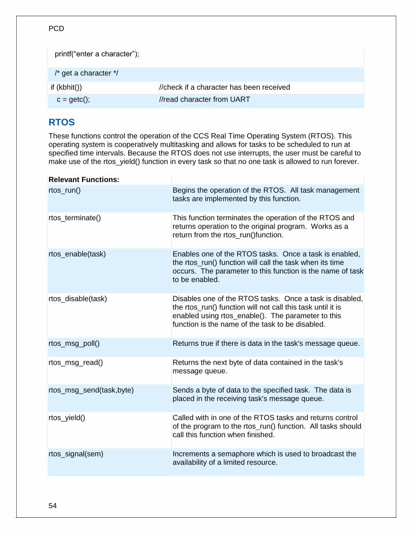
PCD
54
printf(“enter a character”);
/* get a character */
if (kbhit()) //check if a character has been received
c = getc(); //read character from UART
RTOS
These functions control the operation of the CCS Real Time Operating System (RTOS). This operating system is cooperatively multitasking and allows for tasks to be scheduled to run at specified time intervals. Because the RTOS does not use interrupts, the user must be careful to make use of the rtos_yield() function in every task so that no one task is allowed to run forever.
Relevant Functions:
rtos_run() Begins the operation of the RTOS. All task management tasks are implemented by this function.
rtos_terminate() This function terminates the operation of the RTOS and returns operation to the original program. Works as a return from the rtos_run()function.
rtos_enable(task) Enables one of the RTOS tasks. Once a task is enabled, the rtos_run() function will call the task when its time occurs. The parameter to this function is the name of task to be enabled.
rtos_disable(task) Disables one of the RTOS tasks. Once a task is disabled, the rtos_run() function will not call this task until it is enabled using rtos_enable(). The parameter to this function is the name of the task to be disabled.
rtos_msg_poll() Returns true if there is data in the task's message queue.
rtos_msg_read() Returns the next byte of data contained in the task's message queue.
rtos_msg_send(task,byte) Sends a byte of data to the specified task. The data is placed in the receiving task's message queue.
rtos_yield() Called with in one of the RTOS tasks and returns control of the program to the rtos_run() function. All tasks should call this function when finished.
rtos_signal(sem) Increments a semaphore which is used to broadcast the availability of a limited resource.

Functional Overview
55
rtos_wait(sem) Waits for the resource associated with the semaphore to become available and then decrements to semaphore to claim the resource.
rtos_await(expre) Will wait for the given expression to evaluate to true before allowing the task to continue.
rtos_overrun(task) Will return true if the given task over ran its alloted time.
rtos_stats(task,stat) Returns the specified statistic about the specified task. The statistics include the minimum and maximum times for the task to run and the total time the task has spent running.
Relevant Preprocessor:
#USE RTOS(options) This directive is used to specify several different RTOS attributes including the timer to use, the minor cycle time and whether or not statistics should be enabled.
#TASK(options) This directive tells the compiler that the following function is to be an RTOS task.
#TASK
specifies the rate at which the task should be called, the maximum time the task shall be allowed to run, and how large it's queue should be
Relevant Interrupts:
none
Relevant Include Files:
none all functions are built in
Relevant getenv() Parameters:
none
Example Code:
#USE RTOS(timer=0,minor_cycle=20ms)
// RTOS will use timer zero, minor cycle will be 20ms
...
int sem;
...
#TASK(rate=1s,max=20ms,queue=5) // Task will run at a rate of once per second
void task_name(); // with a maximum running time of 20ms and
// a 5 byte queue
rtos_run(); // begins the RTOS
rtos_terminate(); // ends the RTOS
rtos_enable(task_name); // enables the previously declared task.
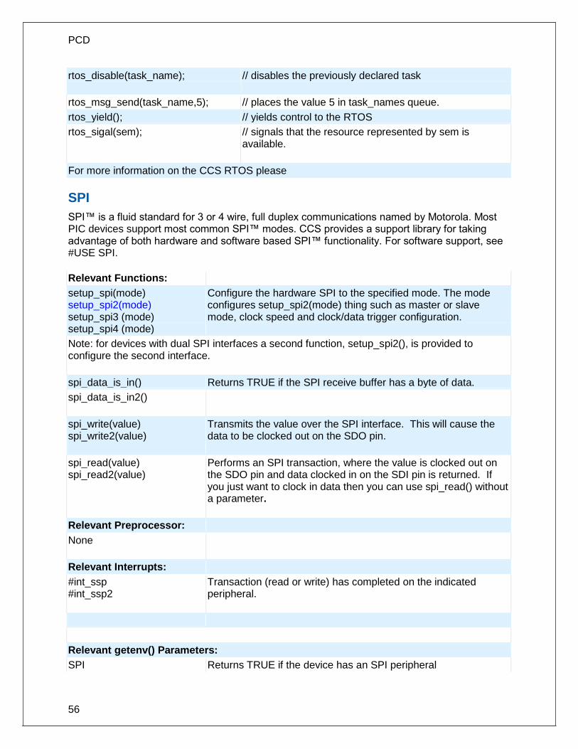
PCD
56
rtos_disable(task_name); // disables the previously declared task
rtos_msg_send(task_name,5); // places the value 5 in task_names queue.
rtos_yield(); // yields control to the RTOS
rtos_sigal(sem); // signals that the resource represented by sem is available.
For more information on the CCS RTOS please
SPI
SPI™ is a fluid standard for 3 or 4 wire, full duplex communications named by Motorola. Most PIC devices support most common SPI™ modes. CCS provides a support library for taking advantage of both hardware and software based SPI™ functionality. For software support, see #USE SPI.
Relevant Functions:
setup_spi(mode) setup_spi2(mode) setup_spi3 (mode) setup_spi4 (mode)
Configure the hardware SPI to the specified mode. The mode configures setup_spi2(mode) thing such as master or slave mode, clock speed and clock/data trigger configuration.
Note: for devices with dual SPI interfaces a second function, setup_spi2(), is provided to configure the second interface.
spi_data_is_in() Returns TRUE if the SPI receive buffer has a byte of data.
spi_data_is_in2()
spi_write(value) spi_write2(value)
Transmits the value over the SPI interface. This will cause the data to be clocked out on the SDO pin.
spi_read(value) spi_read2(value)
Performs an SPI transaction, where the value is clocked out on the SDO pin and data clocked in on the SDI pin is returned. If you just want to clock in data then you can use spi_read() without a parameter.
Relevant Preprocessor:
None
Relevant Interrupts:
#int_ssp #int_ssp2
Transaction (read or write) has completed on the indicated peripheral.
Relevant getenv() Parameters:
SPI Returns TRUE if the device has an SPI peripheral

Functional Overview
57
Example Code:
//configure the device to be a master, data transmitted on H-to-L clock transition
setup_spi(SPI_MASTER | SPI_H_TO_L | SPI_CLK_DIV_16);
spi_write(0x80); //write 0x80 to SPI device
value=spi_read(); //read a value from the SPI device
value=spi_read(0x80); //write 0x80 to SPI device the same time you are reading a value.
Timer0
These options lets the user configure and use timer0. It is available on all devices and is always enabled. The clock/counter is 8-bit on pic16s and 8 or 16 bit on pic18s. It counts up and also provides interrupt on overflow. The options available differ and are listed in the device header file.
Relevant Functions:
setup_timer_0(mode) Sets the source, prescale etc for timer0
set_timer0(value) or set_rtcc(value)
Initializes the timer0 clock/counter. Value may be a 8 bit or 16 bit depending on the device.
value=get_timer0 Returns the value of the timer0 clock/counter
Relevant Preprocessor: None
Relevant Interrupts :
INT_TIMER0 or INT_RTCC Interrupt fires when timer0 overflows
Relevant Include Files:
None, all functions built-in
Relevant getenv() parameters:
TIMER0 Returns 1 if the device has timer0
Example Code:
For PIC18F452
setup_timer_0(RTCC_INTERNAL |RTCC_DIV_2|RTCC_8_BIT);
//sets the internal clock as source //and prescale 2. At 20Mhz timer0
//will increment every 0.4us in this
//setup and overflows every
//102.4us
set_timer0(0); //this sets timer0 register to 0

PCD
58
time=get_timer0(); //this will read the timer0 register
//value
Timer1
These options lets the user configure and use timer1. The clock/counter is 16-bit on pic16s and pic18s. It counts up and also provides interrupt on overflow. The options available differ and are listed in the device header file.
Relevant Functions:
setup_timer_1(mode) Disables or sets the source and prescale for timer1
set_timer1(value) Initializes the timer1 clock/counter
value=get_timer1 Returns the value of the timer1 clock/counter
Relevant Preprocessor:
None
Relevant Interrupts:
INT_TIMER1 Interrupt fires when timer1 overflows
Relevant Include Files:
None, all functions built-in
Relevant getenv() parameters:
TIMER1 Returns 1 if the device has timer1
Example Code:
For PIC18F452
setup_timer_1(T1_DISABLED); //disables timer1
or
setup_timer_1(T1_INTERNAL|T1_DIV_BY_8); //sets the internal clock as source
//and prescale as 8. At 20Mhz timer1 will increment
//every 1.6us in this setup and overflows every
//104.896ms
set_timer1(0); //this sets timer1 register to 0
time=get_timer1(); //this will read the timer1 register value
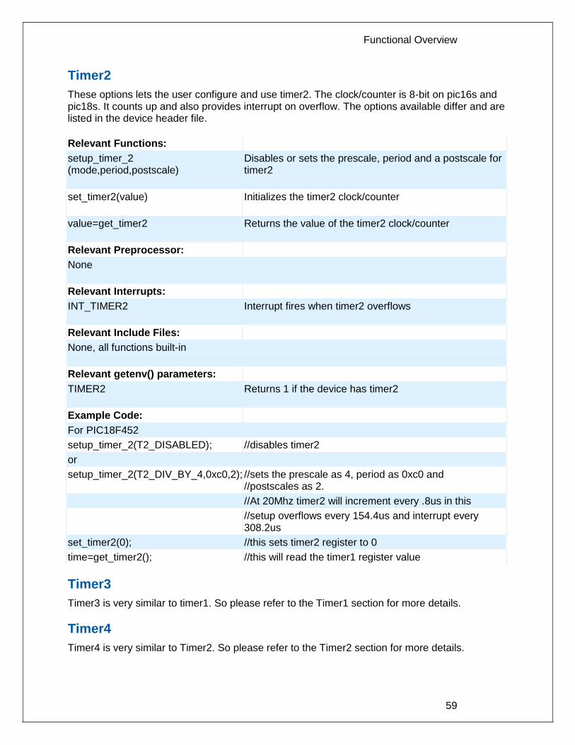
Functional Overview
59
Timer2
These options lets the user configure and use timer2. The clock/counter is 8-bit on pic16s and pic18s. It counts up and also provides interrupt on overflow. The options available differ and are listed in the device header file.
Relevant Functions:
setup_timer_2 (mode,period,postscale)
Disables or sets the prescale, period and a postscale for timer2
set_timer2(value)
Initializes the timer2 clock/counter
value=get_timer2 Returns the value of the timer2 clock/counter
Relevant Preprocessor:
None
Relevant Interrupts:
INT_TIMER2 Interrupt fires when timer2 overflows
Relevant Include Files:
None, all functions built-in
Relevant getenv() parameters:
TIMER2 Returns 1 if the device has timer2
Example Code:
For PIC18F452
setup_timer_2(T2_DISABLED); //disables timer2
or
setup_timer_2(T2_DIV_BY_4,0xc0,2); //sets the prescale as 4, period as 0xc0 and //postscales as 2.
//At 20Mhz timer2 will increment every .8us in this
//setup overflows every 154.4us and interrupt every 308.2us
set_timer2(0); //this sets timer2 register to 0
time=get_timer2(); //this will read the timer1 register value
Timer3
Timer3 is very similar to timer1. So please refer to the Timer1 section for more details.
Timer4
Timer4 is very similar to Timer2. So please refer to the Timer2 section for more details.

PCD
60
Timer5
These options lets the user configure and use timer5. The clock/counter is 16-bit and is available only on 18Fxx31 devices. It counts up and also provides interrupt on overflow. The options available differ and are listed in the device header file.
Relevant Functions:
setup_timer_5(mode) Disables or sets the source and prescale for imer5
set_timer5(value) Initializes the timer5 clock/counter
value=get_timer5 Returns the value of the timer51 clock/counter
Relevant Preprocessor:
None
Relevant Interrupts :
INT_TIMER5 Interrupt fires when timer5 overflows
Relevant Include Files: None, all functions built-in
Relevant getenv() parameters:
TIMER5 Returns 1 if the device has timer5
Example Code:
For PIC18F4431
setup_timer_5(T5_DISABLED) //disables timer5
or
setup_timer_5(T5_INTERNAL|T5_DIV_BY_1); //sets the internal clock as source and //prescale as 1.
//At 20Mhz timer5 will increment every .2us in this
//setup and overflows every 13.1072ms
set_timer5(0); //this sets timer5 register to 0
time=get_timer5(); //this will read the timer5 register value
TimerA
These options lets the user configure and use timerA. It is available on devices with Timer A hardware. The clock/counter is 8 bit. It counts up and also provides interrupt on overflow. The options available are listed in the device's header file.
Relevant Functions:
setup_timer_A(mode) Disable or sets the source and prescale for timerA
set_timerA(value) Initializes the timerA clock/counter

Functional Overview
61
value=get_timerA() Returns the value of the timerA clock/counter
Relevant Preprocessor:
None
Relevant Interrupts :
INT_TIMERA Interrupt fires when timerA overflows
Relevant Include Files: None, all functions built-in
Relevant getenv() parameters:
TIMERA Returns 1 if the device has timerA
Example Code:
setup_timer_A(TA_OFF); //disable timerA
or
setup_timer_A //sets the internal clock as source
(TA_INTERNAL | TA_DIV_8); //and prescale as 8. At 20MHz timerA will increment
//every 1.6us in this setup and overflows every
//409.6us
set_timerA(0); //this sets timerA register to 0
time=get_timerA(); //this will read the timerA register value
TimerB
These options lets the user configure and use timerB. It is available on devices with TimerB hardware. The clock/counter is 8 bit. It counts up and also provides interrupt on overflow. The options available are listed in the device's header file.
Relevant Functions:
setup_timer_B(mode) Disable or sets the source and prescale for timerB
set_timerB(value) Initializes the timerB clock/counter
value=get_timerB() Returns the value of the timerB clock/counter
Relevant Preprocessor:
None
Relevant Interrupts :
INT_TIMERB Interrupt fires when timerB overflows
Relevant Include Files: None, all functions built-in
Relevant getenv() parameters:
TIMERB Returns 1 if the device has timerB
Example Code:
setup_timer_B(TB_OFF); //disable timerB

PCD
62
or
setup_timer_B //sets the internal clock as source
(TB_INTERNAL | TB_DIV_8); //and prescale as 8. At 20MHz timerB will increment
//every 1.6us in this setup and overflows every
//409.6us
set_timerB(0); //this sets timerB register to 0
time=get_timerB(); //this will read the timerB register value
USB
Universal Serial Bus, or USB, is used as a method for peripheral devices to connect to and talk to a personal computer. CCS provides libraries for interfacing a PIC to PC using USB by using a PIC with an internal USB peripheral (like the PIC16C765 or the PIC18F4550 family) or by using any PIC with an external USB peripheral (the National USBN9603 family).
Relevant Functions:
usb_init() Initializes the USB hardware. Will then wait in an infinite loop for the USB peripheral to be connected to bus (but that doesn't mean it has been enumerated by the PC). Will enable and use the USB interrupt.
usb_init_cs() The same as usb_init(), but does not wait for the device to be connected to the bus. This is useful if your device is not bus powered and can operate without a USB connection.
usb_task() If you use connection sense, and the usb_init_cs() for initialization, then you must periodically call this function to keep an eye on the connection sense pin. When the PIC is connected to the BUS, this function will then perpare the USB peripheral. When the PIC is disconnected from the BUS, it will reset the USB stack and peripheral. Will enable and use the USB interrupt.
Note: In your application you must define USB_CON_SENSE_PIN to the connection sense pin.
usb_detach() Removes the PIC from the bus. Will be called automatically by usb_task() if connection is lost, but can be called manually by the user.
usb_attach() Attaches the PIC to the bus. Will be called automatically by usb_task() if connection is made, but can be called manually by the user.
usb_attached() If using connection sense pin (USB_CON_SENSE_PIN), returns TRUE if that pin is high. Else will always return TRUE.
usb_enumerated() Returns TRUE if the device has been enumerated by the PC. If the device has been enumerated by the PC, that means it is in normal operation mode and you can send/receive packets.
usb_put_packet Places the packet of data into the specified endpoint buffer. Returns

Functional Overview
63
(endpoint, data, len, tgl) TRUE if success, FALSE if the buffer is still full with the last packet.
usb_puts (endpoint, data, len, timeout)
Sends the following data to the specified endpoint. usb_puts() differs from usb_put_packet() in that it will send multi packet messages if the data will not fit into one packet.
usb_kbhit(endpoint) Returns TRUE if the specified endpoint has data in it's receive buffer
usb_get_packet (endpoint, ptr, max)
Reads up to max bytes from the specified endpoint buffer and saves it to the pointer ptr. Returns the number of bytes saved to ptr.
usb_gets(endpoint, ptr, max, timeout)
Reads a message from the specified endpoint. The difference usb_get_packet() and usb_gets() is that usb_gets() will wait until a full message has received, which a message may contain more than one packet. Returns the number of bytes received.
Relevant CDC Functions:
A CDC USB device will emulate an RS-232 device, and will appear on your PC as a COM port. The follow functions provide you this virtual RS-232/serial interface
Note: When using the CDC library, you can use the same functions above, but do not use the packet related function such as usb_kbhit(), usb_get_packet(), etc.
usb_cdc_kbhit() The same as kbhit(), returns TRUE if there is 1 or more character in the receive buffer.
usb_cdc_getc() The same as getc(), reads and returns a character from the receive buffer. If there is no data in the receive buffer it will wait indefinitely until there a character has been received.
usb_cdc_putc(c) The same as putc(), sends a character. It actually puts a character into the transmit buffer, and if the transmit buffer is full will wait indefinitely until there is space for the character.
usb_cdc_putc_fast(c) The same as usb_cdc_putc(), but will not wait indefinitely until there is space for the character in the transmit buffer. In that situation the character is lost.
usb_cdc_puts(*str) Sends a character string (null terminated) to the USB CDC port. Will return FALSE if the buffer is busy, TRUE if buffer is string was put into buffer for sending. Entire string must fit into endpoint, if string is longer than endpoint buffer then excess characters will be ignored.
usb_cdc_putready() Returns TRUE if there is space in the transmit buffer for another character.

PCD
64
Relevant Preporcessor:
None
Relevant Interrupts:
#int_usb A USB event has happened, and requires application intervention. The USB library that CCS provides handles this interrupt automatically.
Relevant Include files:
pic_usb.h Hardware layer driver for the PIC16C765 family PICmicro controllers with an internal USB peripheral.
pic18_usb.h Hardware layer driver for the PIC18F4550 family PICmicro controllers with an internal USB peripheral.
usbn960x.h Hardware layer driver for the National USBN9603/USBN9604 external USB peripheral. You can use this external peripheral to add USB to any microcontroller.
usb.h Common definitions and prototypes used by the USB driver
usb.c The USB stack, which handles the USB interrupt and USB Setup Requests on Endpoint 0.
usb_cdc.h A driver that takes the previous include files to make a CDC USB device, which emulates an RS232 legacy device and shows up as a COM port in the MS Windows device manager.
Relevant getenv() Parameters:
USB Returns TRUE if the PICmicro controller has an integrated internal USB peripheral.
Example Code:
Due to the complexity of USB example code will not fit here. But you can find the following examples installed with your CCS C Compiler:
ex_usb_hid.c A simple HID device
ex_usb_mouse.c A HID Mouse, when connected to your PC the mouse cursor will go in circles.
ex_usb_kbmouse.c An example of how to create a USB device with multiple interfaces by creating a keyboard and mouse in one device.
ex_usb_kbmouse2.c An example of how to use multiple HID report Ids to transmit more than

Functional Overview
65
one type of HID packet, as demonstrated by a keyboard and mouse on one device.
ex_usb_scope.c A vendor-specific class using bulk transfers is demonstrated.
ex_usb_serial.c The CDC virtual RS232 library is demonstrated with this RS232 < - > USB example.
ex_usb_serial2.c Another CDC virtual RS232 library example, this time a port of the ex_intee.c example to use USB instead of RS232.
Voltage Reference
These functions configure the votlage reference module. These are available only in the supported chips.
Relevant Functions:
setup_vref(mode | value) Enables and sets up the internal voltage reference value. Constants are defined in the device's .h file.
Relevant Preprocesser: none
Relevant Interrupts: none
Relevant Include Files: none, all functions built-in
Relevant getenv() parameters:
VREF Returns 1 if the device has VREF
Example code:
for PIC12F675
#INT_COMP //comparator interrupt handler void isr() { safe_conditions = FALSE; printf("WARNING!!!! Voltage level is above 3.6V. \r\n"); } setup_comparator(A1_VR_OUT_ON_A2)//sets 2 comparators(A1 and VR and A2 as output) { setup_vref(VREF_HIGH | 15);//sets 3.6(vdd * value/32 + vdd/4) if vdd is 5.0V enable_interrupts(INT_COMP); // enable the comparator interrupt enable_interrupts(GLOBAL); //enable global interrupts }

PCD
66
WDT or Watch Dog Timer
Different chips provide different options to enable/disable or configure the WDT.
Relevant Functions:
setup_wdt() Enables/disables the wdt or sets the prescalar.
restart_wdt() Restarts the wdt, if wdt is enables this must be periodically called to prevent a timeout reset.
For PCB/PCM chips it is enabled/disabled using WDT or NOWDT fuses whereas on PCH device it is done using the setup_wdt function.
The timeout time for PCB/PCM chips are set using the setup_wdt function and on PCH using fuses like WDT16, WDT256 etc. RESTART_WDT when specified in #USE DELAY, #USE I2C and #USE RS232 statements like this #USE DELAY(clock=20000000, restart_wdt) will cause the wdt to restart if it times out during the delay or I2C_READ or GETC.
Relevant Preprocessor:
#FUSES WDT/NOWDT Enabled/Disables wdt in PCB/PCM devices
#FUSES WDT16 Sets ups the timeout time in PCH devices
Relevant Interrupts:
None
Relevant Include Files:
None, all functions built-in
Relevant getenv() parameters:
None
Example Code:
For PIC16F877
#fuses wdt setup_wdt(WDT_2304MS);
while(true){
restart_wdt();
perform_activity();
}
For PIC18F452
#fuse WDT1
setup_wdt(WDT_ON);
while(true){
restart_wdt();
perform_activity();

Functional Overview
67
}
Some of the PCB chips are share the WDT prescalar bits with timer0 so the WDT prescalar constants can be used with setup_counters or setup_timer0 or setup_wdt functions.
interrupt_enabled()
This function checks the interrupt enabled flag for the specified interrupt and returns TRUE if set.
Syntax interrupt_enabled(interrupt);
Parameters interrupt- constant specifying the interrupt
Returns Boolean value
Function The function checks the interrupt enable flag of the specified interrupt and returns TRUE when set.
Availability Devices with interrupts
Requires Interrupt constants defined in the device's .h file.
Examples if(interrupt_enabled(INT_RDA)) disable_interrupt(INT_RDA);
Example Files None
Also see DISABLE_INTERRUPTS(), , Interrupts Overview, CLEAR_INTERRUPT(), ENABLE_INTERRUPTS(),,INTERRUPT_ACTIVE()
Stream I/O
Syntax: #include <ios.h> is required to use any of the ios identifiers.
Output: output: stream << variable_or_constant_or_manipulator ; ________________________________ one or more repeats stream may be the name specified in the #use RS232 stream= option or for the default stream use cout. stream may also be the name of a char array. In this case the data is written to the array with a 0 terminator. stream may also be the name of a function that accepts a single char parameter. In this case the function is called for each character to be output. variables/constants: May be any integer, char, float or fixed type. Char arrays are output as strings and all other types are output as an address of the variable. manipulators: hex -Hex format numbers dec- Decimal format numbers (default) setprecision(x) -Set number of places after the decimal point

PCD
68
setw(x) -Set total number of characters output for numbers boolalpha- Output int1 as true and false noboolalpha -Output int1 as 1 and 0 (default) fixed Floats- in decimal format (default) scientific Floats- use E notation iosdefault- All manipulators to default settings endl -Output CR/LF ends- Outputs a null ('\000')
Examples: cout << "Value is " << hex << data << endl; cout << "Price is $" << setw(4) << setprecision(2) << cost << endl; lcdputc << '\f' << setw(3) << count << " " << min << " " << max; string1 << setprecision(1) << sum / count; string2 << x << ',' << y;
Input: stream >> variable_or_constant_or_manipulator ; ________________________________ one or more repeats stream may be the name specified in the #use RS232 stream= option or for the default stream use cin. stream may also be the name of a char array. In this case the data is read from the array up to the 0 terminator. stream may also be the name of a function that returns a single char and has no parameters. In this case the function is called for each character to be input. Make sure the function returns a \r to terminate the input statement. variables/constants: May be any integer, char, float or fixed type. Char arrays are input as strings. Floats may use the E format. Reading of each item terminates with any character not valid for the type. Usually items are separated by spaces. The termination character is discarded. At the end of any stream input statement characters are read until a return (\r) is read. No termination character is read for a single char input. manipulators: hex -Hex format numbers dec- Decimal format numbers (default) noecho- Suppress echoing strspace- Allow spaces to be input into strings nostrspace- Spaces terminate string entry (default) iosdefault -All manipulators to default settings
Examples: cout << "Enter number: "; cin >> value; cout << "Enter title: "; cin >> strspace >> title; cin >> data[i].recordid >> data[i].xpos >> data[i].ypos >> data[i].sample ; string1 >> data; lcdputc << "\fEnter count"; lcdputc << keypadgetc >> count; // read from keypad, echo to lcd

Functional Overview
69
// This syntax only works with // user defined functions.
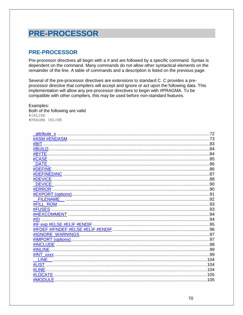
70
PRE-PROCESSOR
PRE-PROCESSOR
Pre-processor directives all begin with a # and are followed by a specific command. Syntax is dependent on the command. Many commands do not allow other syntactical elements on the remainder of the line. A table of commands and a description is listed on the previous page. Several of the pre-processor directives are extensions to standard C. C provides a pre-processor directive that compilers will accept and ignore or act upon the following data. This implementation will allow any pre-processor directives to begin with #PRAGMA. To be compatible with other compilers, this may be used before non-standard features. Examples: Both of the following are valid #INLINE
#PRAGMA INLINE
_attribute_x ...........................................................................................................................72 #ASM #ENDASM ..................................................................................................................73 #BIT ......................................................................................................................................83 #BUILD ..................................................................................................................................84 #BYTE ...................................................................................................................................84 #CASE ..................................................................................................................................85 _DATE_ .................................................................................................................................86 #DEFINE ...............................................................................................................................86 #DEFINEDINC ......................................................................................................................87 #DEVICE ...............................................................................................................................88 _DEVICE_ .............................................................................................................................90 #ERROR ...............................................................................................................................90 #EXPORT (options) ...............................................................................................................91 __FILENAME__ ....................................................................................................................92 #FILL_ROM ...........................................................................................................................93 #FUSES ................................................................................................................................93 #HEXCOMMENT ..................................................................................................................94 #ID ........................................................................................................................................94 #IF exp #ELSE #ELIF #ENDIF ..............................................................................................95 #IFDEF #IFNDEF #ELSE #ELIF #ENDIF ..............................................................................96 #IGNORE_WARNINGS .........................................................................................................97 #IMPORT (options)................................................................................................................97 #INCLUDE ............................................................................................................................98 #INLINE .................................................................................................................................99 #INT_xxxx .............................................................................................................................99 __LINE__ ............................................................................................................................ 104 #LIST .................................................................................................................................. 104 #LINE .................................................................................................................................. 104 #LOCATE ............................................................................................................................ 105 #MODULE ........................................................................................................................... 105

Pre-Processor
71
#NOLIST ............................................................................................................................. 106 #OCS .................................................................................................................................. 107 #OPT ................................................................................................................................... 107 #ORG .................................................................................................................................. 107 #PIN_SELECT .................................................................................................................... 109 __PCB__ ............................................................................................................................. 111 __ PCM __ .......................................................................................................................... 112 __ PCH __ ........................................................................................................................... 112 #PRAGMA ........................................................................................................................... 113 #PRIORITY ......................................................................................................................... 113 #PROFILE ........................................................................................................................... 113 #RESERVE ......................................................................................................................... 114 #ROM .................................................................................................................................. 115 #SEPARATE ....................................................................................................................... 116 #SERIALIZE ........................................................................................................................ 116 #TASK ................................................................................................................................. 118 __ TIME __ .......................................................................................................................... 119 #TYPE ................................................................................................................................. 119 #UNDEF .............................................................................................................................. 120 #USE CAPTURE ................................................................................................................. 121 #USE DELAY ...................................................................................................................... 122 #USE DYNAMIC_MEMORY ................................................................................................ 123 #USE FAST_IO ................................................................................................................... 123 #USE FIXED_IO .................................................................................................................. 124 #USE I2C ............................................................................................................................ 124 #USE PROFILE() ................................................................................................................ 126 #USE PWM ......................................................................................................................... 126 #USE RS232 ...................................................................................................................... 128 #USE RTOS ....................................................................................................................... 132 #USE SPI ............................................................................................................................ 133 #USE STANDARD_IO ......................................................................................................... 134 #USE TIMER ....................................................................................................................... 135 #USE TOUCHPAD .............................................................................................................. 136 #WARNING ......................................................................................................................... 137 #WORD ............................................................................................................................... 138 #ZERO_RAM ...................................................................................................................... 139

PCD
72
_attribute_x
Syntax: _attribute_x
Elements:
x is the attribute you want to apply. Valid values for x are as follows: packed By default each element in a struct or union are padded to be evenly spaced by the size of 'int'. This is to prevent an address violation when accessing an element of struct. See the following example: struct { int8 a; int8 b; } test; On architectures where 'int' is 16bit (such as dsPIC or PIC24 PICmicrocontrollers), 'test' would take 4 bytes even though it is comprised of two 8-bit elements. By applying the 'packed' attribute to this struct then it would take 2 bytes as originally intended: struct __attribute__(packed) { int8 a; int8 b; } test; Care should be taken by the user when accessing individual elements of a packed struct – creating a pointer to 'b' in 'test' and attempting to dereference that pointer would cause an access violation. Any attempts to read/write 'b' should be done in context of 'test' so the compiler knows it is packed: test.b = 5; aligned(y) By default the compiler will alocate a variable in the first free memory location. The aligned attribute will force the compiler to allocate a location for the specified variable at a location that is modulus of the y parameter. For example: int8 array[256] __attribute__(aligned(0x1000)); This will tell the compiler to try to place 'array' at either 0x0, 0x1000, 0x2000, 0x3000, 0x4000, etc.
Purpose To alter some specifics as to how the compiler operates
Examples:
struct attribute__(packed__) { int8 a; int8 b; } test; int8 array[256] __attribute__(aligned(0x1000));
Example Files: None

Pre-Processor
73
#ASM #ENDASM
Syntax: #ASM or #ASM ASIS code #ENDASM
Elements: code is a list of assembly language instructions
Examples:
int_ffind_parity(int data){int count;, result,datal; data1=data; asm MOV #0x08, MOV WF, count CLRF result Loop: MOVF data1,w XORWF result, F RRCF data1,F DECFSZ count,F BRA LOOP MOVLW 0x01 ANDWF resutt, F #end asm retturn (result)'; }
Example Files: ex_glint.c
Also See: None
ADD Wa,Wb,Wd Wd = Wa+Wb
ADD f,W W0 = f+Wd
ADD lit10,Wd Wd = lit10+Wd
ADD Wa,lit5,Wd Wd = lit5+Wa
ADD f,F f = f+Wd
ADD acc Acc = AccA+AccB
ADD Wd,{lit4},acc Acc = Acc+(Wa shifted slit4)
ADD.B lit10,Wd Wd = lit10+Wd (byte)
ADD Wd,{lit4},acc Acc = Acc+(Wa shifted slit4)
ADD.B lit10,Wd Wd = lit10+Wd (byte)
ADD.B f,F f = f+Wd (byte)
ADD.B Wa,Wb,Wd Wd = Wa+Wb (byte)
ADD.B Wa,lit5,Wd Wd = lit5+Wa (byte)
ADD.B f,W W0 = f+Wd (byte)
ADDC f,W Wd = f+Wa+C
ADDC lit10,Wd Wd = lit10+Wd+C
ADDC Wa,lit5,Wd Wd = lit5+Wa+C
ADDC f,F Wd = f+Wa+C
ADDC Wa,Wb,Wd Wd = Wa+Wb+C
ADDC.B lit10,Wd Wd = lit10+Wd+C(byte)
ADDC.B Wa,Wb,Wd Wd = Wa+Wb+C(byte)
ADDC.B Wa,lit5,Wd Wd = lit5+Wa+C(byte)
ADDC.B f,W Wd = f+Wa+C(byte)
ADDC.B f,F Wd = f+Wa+C(byte)
AND Wa,Wb,Wd Wd = Wa.&.Wb

PCD
74
AND lit10,Wd Wd = lit10.&.Wd
AND f,W W0 = f.&.Wa
AND f,F f = f.&.Wa
AND Wa,lit5,Wd Wd = lit5.&.Wa
AND.B f,W W0 = f.&.Wa (byte)
AND.B Wa,Wb,Wd Wd = Wa.&.Wb (byte)
AND.B lit10,Wd Wd = lit10.&.Wd (byte)
AND.B f,F f = f.&.Wa (byte)
AND.B Wa,lit5,Wd Wd = lit5.&.Wa (byte)
ASR f,W W0 = f >> 1arithmetic
ASR f,F f = f >> 1arithmetic
ASR Wa,Wd Wd = Wa >> 1arithmetic
ASR Wa,lit4,Wd Wd = Wa >> lit4arithmetic
ASR Wa,Wb,Wd Wd = Wa >> Wbarithmetic
ASR.B f,F f = f >> 1arithmetic (byte)
ASR.B f,W W0 = f >> 1arithmetic (byte)
ASR.B Wa,Wd Wd = Wa >> 1arithmetic (byte)
BCLR f,B f.bit = 0
BCLR Wd,B Wa.bit = 0
BCLR.B Wd,B Wa.bit = 0 (byte)
BRA a Branch unconditionally
BRA Wd Branch PC+Wa
BRA BZ a Branch if Zero
BRA C a Branch if Carry (no borrow)
BRA GE a Branch if greater than or equal
BRA GEU a Branch if unsigned greater than or equal
BRA GT a Branch if greater than
BRA GTU a Branch if unsigned greater than
BRA LE a Branch if less than or equal
BRA LEU a Branch if unsigned less than or equal
BRA LT a Branch if less than
BRA LTU a Branch if unsigned less than
BRA N a Branch if negative
BRA NC a Branch if not carry (Borrow)
BRA NN a Branch if not negative
BRA NOV a Branch if not Overflow
BRA NZ a Branch if not Zero
BRA OA a Branch if Accumulator A overflow
BRA OB a Branch if Accumulator B overflow
BRA OV a Branch if Overflow
BRA SA a Branch if Accumulator A Saturate

Pre-Processor
75
BRA SB a Branch if Accumulator B Saturate
BRA Z a Branch if Zero
BREAK ICD Break
BSET Wd,B Wa.bit = 1
BSET f,B f.bit = 1
BSET.B Wd,B Wa.bit = 1 (byte)
BSW.C Wa,Wd Wa.Wb = C
BSW.Z Wa,Wd Wa.Wb = Z
BTG Wd,B Wa.bit = ~Wa.bit
BTG f,B f.bit = ~f.bit
BTG.B Wd,B Wa.bit = ~Wa.bit (byte)
BTSC f,B Skip if f.bit = 0
BTSC Wd,B Skip if Wa.bit4 = 0
BTSS f,B Skip if f.bit = 1
BTSS Wd,B Skip if Wa.bit = 1
BTST f,B Z = f.bit
BTST.C Wa,Wd C = Wa.Wb
BTST.C Wd,B C = Wa.bit
BTST.Z Wd,B Z = Wa.bit
BTST.Z Wa,Wd Z = Wa.Wb
BTSTS f,B Z = f.bit; f.bit = 1
BTSTS.C Wd,B C = Wa.bit; Wa.bit = 1
BTSTS.Z Wd,B Z = Wa.bit; Wa.bit = 1
CALL a Call subroutine
CALL Wd Call [Wa]
CLR f,F f = 0
CLR acc,da,dc,pi Acc = 0; prefetch=0
CLR f,W W0 = 0
CLR Wd Wd = 0
CLR.B f,W W0 = 0 (byte)
CLR.B Wd Wd = 0 (byte)
CLR.B f,F f = 0 (byte)
CLRWDT Clear WDT
COM f,F f = ~f
COM f,W W0 = ~f
COM Wa,Wd Wd = ~Wa
COM.B f,W W0 = ~f(byte)
COM.B Wa,Wd Wd = ~Wa (byte)
COM.B f,F f = ~f(byte)
CP W,f Status set for f - W0
CP Wa,Wd Status set for Wb – Wa

PCD
76
CP Wd,lit5 Status set for Wa – lit5
CP.B W,f Status set for f - W0 (byte)
CP.B Wa,Wd Status set for Wb – Wa (byte)
CP.B Wd,lit5 Status set for Wa – lit5 (byte)
CP0 Wd Status set for Wa – 0
CP0 W,f Status set for f – 0
CP0.B Wd Status set for Wa – 0 (byte)
CP0.B W,f Status set for f – 0 (byte)
CPB Wd,lit5 Status set for Wa – lit5 – C
CPB Wa,Wd Status set for Wb – Wa – C
CPB W,f Status set for f – W0 - C
CPB.B Wa,Wd Status set for Wb – Wa – C (byte)
CPB.B Wd,lit5 Status set for Wa – lit5 – C(byte)
CPB.B W,f Status set for f – W0 - C (byte)
CPSEQ Wa,Wd Skip if Wa = Wb
CPSEQ.B Wa,Wd Skip if Wa = Wb (byte)
CPSGT Wa,Wd Skip if Wa > Wb
CPSGT.B Wa,Wd Skip if Wa > Wb (byte)
CPSLT Wa,Wd Skip if Wa < Wb
CPSLT.B Wa,Wd Skip if Wa < Wb (byte)
CPSNE Wa,Wd Skip if Wa != Wb
CPSNE.B Wa,Wd Skip if Wa != Wb (byte)
DAW.B Wd Wa = decimal adjust Wa
DEC Wa,Wd Wd = Wa – 1
DEC f,W W0 = f – 1
DEC f,F f = f – 1
DEC.B f,F f = f – 1 (byte)
DEC.B f,W W0 = f – 1 (byte)
DEC.B Wa,Wd Wd = Wa – 1 (byte)
DEC2 Wa,Wd Wd = Wa – 2
DEC2 f,W W0 = f – 2
DEC2 f,F f = f – 2
DEC2.B Wa,Wd Wd = Wa – 2(byte)
DEC2.B f,W W0 = f – 2 (byte)
DEC2.B f,F f = f – 2 (byte)
DISI lit14 Disable Interrupts lit14 cycles
DIV.S Wa,Wd Signed 16/16-bit integer divide
DIV.SD Wa,Wd Signed 16/16-bit integer divide (dword)
DIV.U Wa,Wd UnSigned 16/16-bit integer divide
DIV.UD Wa,Wd UnSigned 16/16-bit integer divide (dword)
DIVF Wa,Wd Signed 16/16-bit fractional divide

Pre-Processor
77
DO lit14,a Do block lit14 times
DO Wd,a Do block Wa times
ED Wd*Wd,acc,da,db Euclidean Distance (No Accumulate)
EDAC Wd*Wd,acc,da,db Euclidean Distance
EXCH Wa,Wd Swap Wa and Wb
FBCL Wa,Wd Find bit change from left (Msb) side
FEX ICD Execute
FF1L Wa,Wd Find first one from left (Msb) side
FF1R Wa,Wd Find first one from right (Lsb) side
GOTO a GoTo
GOTO Wd GoTo [Wa]
INC f,W W0 = f + 1
INC Wa,Wd Wd = Wa + 1
INC f,F f = f + 1
INC.B Wa,Wd Wd = Wa + 1 (byte)
INC.B f,F f = f + 1 (byte)
INC.B f,W W0 = f + 1 (byte)
INC2 f,W W0 = f + 2
INC2 Wa,Wd Wd = Wa + 2
INC2 f,F f = f + 2
INC2.B f,W W0 = f + 2 (byte)
INC2.B f,F f = f + 2 (byte)
INC2.B Wa,Wd Wd = Wa + 2 (byte)
IOR lit10,Wd Wd = lit10 | Wd
IOR f,F f = f | Wa
IOR f,W W0 = f | Wa
IOR Wa,lit5,Wd Wd = Wa.|.lit5
IOR Wa,Wb,Wd Wd = Wa.|.Wb
IOR.B Wa,Wb,Wd Wd = Wa.|.Wb (byte)
IOR.B f,W W0 = f | Wa (byte)
IOR.B lit10,Wd Wd = lit10 | Wd (byte)
IOR.B Wa,lit5,Wd Wd = Wa.|.lit5 (byte)
IOR.B f,F f = f | Wa (byte)
LAC Wd,{lit4},acc Acc = Wa shifted slit4
LNK lit14 Allocate Stack Frame
LSR f,W W0 = f >> 1
LSR Wa,lit4,Wd Wd = Wa >> lit4
LSR Wa,Wd Wd = Wa >> 1
LSR f,F f = f >> 1
LSR Wa,Wb,Wd Wd = Wb >> Wa
LSR.B f,W W0 = f >> 1 (byte)

PCD
78
LSR.B f,F f = f >> 1 (byte)
LSR.B Wa,Wd Wd = Wa >> 1 (byte)
MAC Wd*Wd,acc,da,dc Acc = Acc + Wa * Wa; {prefetch}
MAC Wd*Wc,acc,da,dc, Acc = Acc + Wa * Wb; {[W13] = Acc}; {prefetch}
MOV W,f f = Wa
MOV f,W W0 = f
MOV f,F f = f
MOV Wd,? F = Wa
MOV Wa+lit,Wd Wd = [Wa +Slit10]
MOV ?,Wd Wd = f
MOV lit16,Wd Wd = lit16
MOV Wa,Wd Wd = Wa
MOV Wa,Wd+lit [Wd + Slit10] = Wa
MOV.B lit8,Wd Wd = lit8(byte)
MOV.B W,f f = Wa (byte)
MOV.B f,W W0 = f (byte)
MOV.B f,F f = f (byte)
MOV.B Wa+lit,Wd Wd = [Wa +Slit10] (byte)
MOV.B Wa,Wd+lit [Wd + Slit10] = Wa (byte)
MOV.B Wa,Wd Wd = Wa (byte)
MOV.D Wa,Wd Wd:Wd+1 = Wa:Wa+1
MOV.D Wa,Wd Wd:Wd+1 = Wa:Wa+1
MOVSAC acc,da,dc,pi Move ? to ? and ? To ?
MPY Wd*Wc,acc,da,dc Acc = Wa*Wb
MPY Wd*Wd,acc,da,dc Square to Acc
MPY.N Wd*Wc,acc,da,dc Acc = -(Wa*Wb)
MSC Wd*Wc,acc,da,dc, Acc = Acc – Wa*Wb
MUL W,f W3:W2 = f * Wa
MUL.B W,f W3:W2 = f * Wa (byte)
MUL.SS Wa,Wd {Wd+1,Wd}= sign(Wa) * sign(Wb)
MUL.SU Wa,Wd {Wd+1,Wd} = sign(Wa) * unsign(Wb)
MUL.SU Wa,lit5,Wd {Wd+1,Wd}= sign(Wa) * unsign(lit5)
MUL.US Wa,Wd {Wd+1,Wd} = unsign(Wa) * sign(Wb)
MUL.UU Wa,Wd {Wd+1,Wd} = unsign(Wa) * unsign(Wb)
MUL.UU Wa,lit5,Wd {Wd+1,Wd} = unsign(Wa) * unsign(lit5)
NEG f,F f = - f
PUSH Wd Push Wa to TOS
PUSH.D Wd PUSH double Wa:Wa + 1 to TOS
PUSH.S PUSH shadow registers
PWRSAV lit1 Enter Power-saving mode lit1
RCALL a Call (relative)

Pre-Processor
79
RCALL Wd Call Wa
REPEAT lit14 Repeat next instruction (lit14 + 1) times
REPEAT Wd Repeat next instruction (Wa + 1) times
RESET Reset
RETFIE Return from interrupt enable
RETLW lit10,Wd Return; Wa = lit10
RETLW.B lit10,Wd Return; Wa = lit10 (byte)
RETURN Return
RLC Wa,Wd Wd = rotate left through Carry Wa
RLC f,F f = rotate left through Carry f
RLC f,W W0 = rotate left through Carry f
RLC.B f,F f = rotate left through Carry f (byte)
RLC.B f,W W0 = rotate left through Carry f (byte)
RLC.B Wa,Wd Wd = rotate left through Carry Wa (byte)
RLNC Wa,Wd Wd = rotate left (no Carry) Wa
RLNC f,F f = rotate left (no Carry) f
RLNC f,W W0 = rotate left (no Carry) f
RLNC.B f,W W0 = rotate left (no Carry) f (byte)
RLNC.B Wa,Wd Wd = rotate left (no Carry) Wa (byte)
RLNC.B f,F f = rotate left (no Carry) f (byte)
RRC f,F f = rotate right through Carry f
RRC Wa,Wd Wd = rotate right through Carry Wa
RRC f,W W0 = rotate right through Carry f
RRC.B f,W W0 = rotate right through Carry f (byte)
RRC.B f,F f = rotate right through Carry f (byte)
RRC.B Wa,Wd Wd = rotate right through Carry Wa (byte)
RRNC f,F f = rotate right (no Carry) f
RRNC f,W W0 = rotate right (no Carry) f
RRNC Wa,Wd Wd = rotate right (no Carry) Wa
RRNC.B f,F f = rotate right (no Carry) f (byte)
RRNC.B Wa,Wd Wd = rotate right (no Carry) Wa (byte)
RRNC.B f,W W0 = rotate right (no Carry) f (byte)
SAC acc,{lit4},Wd Wd = Acc slit 4
SAC.R acc,{lit4},Wd Wd = Acc slit 4 with rounding
SE Wa,Wd Wd = sign-extended Wa
SETM Wd Wd = 0xFFFF
SETM f,F W0 = 0xFFFF
SETM.B Wd Wd = 0xFFFF (byte)
SETM.B f,W W0 = 0xFFFF (byte)
SETM.B f,F W0 = 0xFFFF (byte)
SFTAC acc,Wd Arithmetic shift Acc by (Wa)

PCD
80
SFTAC acc,lit5 Arithmetic shift Acc by Slit6
SL f,W W0 = f << 1
SL Wa,Wb,Wd Wd = Wa << Wb
SL Wa,lit4,Wd Wd = Wa << lit4
SL Wa,Wd Wd = Wa << 1
SL f,F f = f << 1
SL.B f,W W0 = f << 1 (byte)
SL.B Wa,Wd Wd = Wa << 1 (byte)
SL.B f,F f = f << 1 (byte)
SSTEP ICD Single Step
SUB f,F f = f – W0
SUB f,W W0 = f – W0
SUB Wa,Wb,Wd Wd = Wa – Wb
SUB Wa,lit5,Wd Wd = Wa – lit5
SUB acc Acc = AccA – AccB
SUB lit10,Wd Wd = Wd – lit10
SUB.B Wa,lit5,Wd Wd = Wa – lit5 (byte)
SUB.B lit10,Wd Wd = Wd – lit10 (byte)
SUB.B f,W W0 = f – W0 (byte)
SUB.B Wa,Wb,Wd Wd = Wa – Wb (byte)
SUB.B f,F f = f – W0 (byte)
SUBB f,W W0 = f – W0 – C
SUBB Wa,Wb,Wd Wd = Wa – Wb – C
SUBB f,F f = f – W0 – C
SUBB Wa,lit5,Wd Wd = Wa – lit5 - C
SUBB lit10,Wd Wd = Wd – lit10 – C
SUBB.B lit10,Wd Wd = Wd – lit10 – C(byte)
SUBB.B Wa,Wb,Wd Wd = Wa – Wb – C(byte)
SUBB.B f,F f = f – W0 – C (byte)
SUBB.B Wa,lit5,Wd Wd = Wa – lit5 - C(byte)
SUBB.B f,W W0 = f – W0 – C (byte)
SUBBR Wa,lit5,Wd Wd = lit5 – Wa - C
SUBBR f,W W0 = W0 – f – C
SUBBR f,F f = W0 – f – C
SUBBR Wa,Wb,Wd Wd = Wa – Wb - C
SUBBR.B f,F f = W0 – f – C(byte)
SUBBR.B f,W W0 = W0 – f – C(byte)
SUBBR.B Wa,Wb,Wd Wd = Wa – Wb - C(byte)
SUBBR.B Wa,lit5,Wd Wd = lit5 – Wa - C(byte)
SUBR Wa,lit5,Wd Wd = lit5 – Wb
SUBR f,F f = W0 – f
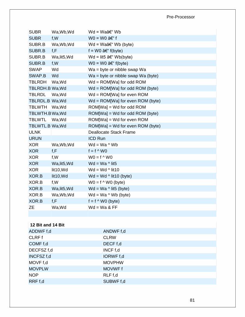
Pre-Processor
81
SUBR Wa,Wb,Wd Wd = Wa– Wb
SUBR f,W W0 = W0 – f
SUBR.B Wa,Wb,Wd Wd = Wa– Wb (byte)
SUBR.B f,F f = W0 – f(byte)
SUBR.B Wa,lit5,Wd Wd = lit5 – Wb(byte)
SUBR.B f,W W0 = W0 – f(byte)
SWAP Wd Wa = byte or nibble swap Wa
SWAP.B Wd Wa = byte or nibble swap Wa (byte)
TBLRDH Wa,Wd Wd = ROM[Wa] for odd ROM
TBLRDH.B Wa,Wd Wd = ROM[Wa] for odd ROM (byte)
TBLRDL Wa,Wd Wd = ROM[Wa] for even ROM
TBLRDL.B Wa,Wd Wd = ROM[Wa] for even ROM (byte)
TBLWTH Wa,Wd ROM[Wa] = Wd for odd ROM
TBLWTH.B Wa,Wd ROM[Wa] = Wd for odd ROM (byte)
TBLWTL Wa,Wd ROM[Wa] = Wd for even ROM
TBLWTL.B Wa,Wd ROM[Wa] = Wd for even ROM (byte)
ULNK Deallocate Stack Frame
URUN ICD Run
XOR Wa,Wb,Wd Wd = Wa ^ Wb
XOR f,F f = f ^ W0
XOR f,W W0 = f ^ W0
XOR Wa,lit5,Wd Wd = Wa ^ lit5
XOR lit10,Wd Wd = Wd ^ lit10
XOR.B lit10,Wd Wd = Wd ^ lit10 (byte)
XOR.B f,W W0 = f ^ W0 (byte)
XOR.B Wa,lit5,Wd Wd = Wa ^ lit5 (byte)
XOR.B Wa,Wb,Wd Wd = Wa ^ Wb (byte)
XOR.B f,F f = f ^ W0 (byte)
ZE Wa,Wd Wd = Wa & FF
12 Bit and 14 Bit
ADDWF f,d ANDWF f,d
CLRF f CLRW
COMF f,d DECF f,d
DECFSZ f,d INCF f,d
INCFSZ f,d IORWF f,d
MOVF f,d MOVPHW
MOVPLW MOVWF f
NOP RLF f,d
RRF f,d SUBWF f,d

PCD
82
SWAPF f,d XORWF f,d
BCF f,b BSF f,b
BTFSC f,b BTFSS f,b
ANDLW k CALL k
CLRWDT GOTO k
IORLW k MOVLW k
RETLW k SLEEP
XORLW OPTION
TRIS k
14 Bit
ADDLW k
SUBLW k
RETFIE
RETURN
f may be a constant (file number) or a simple variable
d may be a constant (0 or 1) or W or F
f,b may be a file (as above) and a constant (0-7) or it may be just a bit variable reference.
k may be a constant expression
Note that all expressions and comments are in C like syntax.
PIC 18
ADDWF f,d ADDWFC f,d ANDWF f,d
CLRF f COMF f,d CPFSEQ f
CPFSGT f CPFSLT f DECF f,d
DECFSZ f,d DCFSNZ f,d INCF f,d
INFSNZ f,d IORWF f,d MOVF f,d
MOVFF fs,d MOVWF f MULWF f
NEGF f RLCF f,d RLNCF f,d
RRCF f,d RRNCF f,d SETF f
SUBFWB f,d SUBWF f,d SUBWFB f,d
SWAPF f,d TSTFSZ f XORWF f,d
BCF f,b BSF f,b BTFSC f,b
BTFSS f,b BTG f,d BC n
BN n BNC n BNN n
BNOV n BNZ n BOV n
BRA n BZ n CALL n,s
CLRWDT - DAW - GOTO n
NOP - NOP - POP -
PUSH - RCALL n RESET -
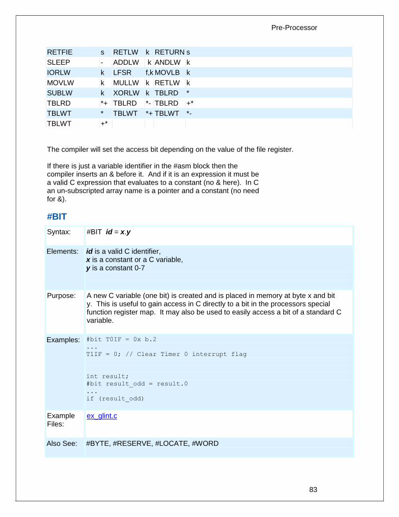
Pre-Processor
83
RETFIE s RETLW k RETURN s
SLEEP - ADDLW k ANDLW k
IORLW k LFSR f,k MOVLB k
MOVLW k MULLW k RETLW k
SUBLW k XORLW k TBLRD *
TBLRD *+ TBLRD *- TBLRD +*
TBLWT * TBLWT *+ TBLWT *-
TBLWT +*
The compiler will set the access bit depending on the value of the file register. If there is just a variable identifier in the #asm block then the compiler inserts an & before it. And if it is an expression it must be a valid C expression that evaluates to a constant (no & here). In C an un-subscripted array name is a pointer and a constant (no need for &).
#BIT
Syntax: #BIT id = x.y
Elements: id is a valid C identifier, x is a constant or a C variable, y is a constant 0-7
Purpose: A new C variable (one bit) is created and is placed in memory at byte x and bit y. This is useful to gain access in C directly to a bit in the processors special function register map. It may also be used to easily access a bit of a standard C variable.
Examples: #bit T0IF = 0x b.2
...
T1IF = 0; // Clear Timer 0 interrupt flag
int result;
#bit result_odd = result.0
...
if (result_odd)
Example Files:
ex_glint.c
Also See: #BYTE, #RESERVE, #LOCATE, #WORD

PCD
84
#BUILD
Syntax: #BUILD(segment = address) #BUILD(segment = address, segment = address) #BUILD(segment = start:end) #BUILD(segment = start: end, segment = start: end) #BUILD(nosleep)
Elements: segment is one of the following memory segments which may be assigned a location: MEMORY, RESET, or INTERRUPT address is a ROM location memory address. Start and end are used to specify a range in memory to be used. start is the first ROM location and end is the last ROM location to be used. nosleep is used to prevent the compiler from inserting a sleep at the end of main() Bootload produces a bootloader-friendly hex file (in order, full block size). NOSLEEP_LOCK is used instead of A sleep at the end of a main A infinite loop.
Purpose: PIC18XXX devices with external ROM or PIC18XXX devices with no internal ROM can direct the compiler to utilize the ROM. When linking multiple compilation units, this directive must appear exactly the same in each compilation unit.
Examples: #build(memory=0x20000:0x2FFFF) //Assigns memory space #build(reset=0x200,interrupt=0x208) //Assigns start
//location
//of reset and
//interrupt
//vectors
#build(reset=0x200:0x207, interrupt=0x208:0x2ff)
//Assign limited space
//for reset and
//interrupt vectors.
#build(memory=0x20000:0x2FFFF) //Assigns memory space
Example Files:
None
Also See: #LOCATE, #RESERVE, #ROM, #ORG
#BYTE
Syntax: #BYTE id = x
Elements: id is a valid C identifier, x is a C variable or a constant
Purpose: If the id is already known as a C variable then this will locate the variable at address

Pre-Processor
85
x. In this case the variable type does not change from the original definition. If the id is not known a new C variable is created and placed at address x with the type int (8 bit) Warning: In both cases memory at x is not exclusive to this variable. Other variables may be located at the same location. In fact when x is a variable, then id and x share the same memory location.
Examples: #byte status = 3
#byte b_port = 6
struct {
short int r_w;
short int c_d;
int unused : 2;
int data : 4 ; } a _port;
#byte a_port = 5
...
a_port.c_d = 1;
Example Files:
ex_glint.c
Also See: #BIT, #LOCATE, #RESERVE, #WORD
#CASE
Syntax: #CASE
Elements: None
Purpose: Will cause the compiler to be case sensitive. By default the compiler is case insensitive. When linking multiple compilation units, this directive must appear exactly the same in each compilation unit. Warning: Not all the CCS example programs, headers and drivers have been tested with case sensitivity turned on.
Examples: #case
int STATUS;
void func() {
int status;
...
STATUS = status; // Copy local status to
//global
}
Example Files:
ex_cust.c

PCD
86
Also See: None
_DATE_
Syntax: __DATE__
Elements: None
Purpose: This pre-processor identifier is replaced at compile time with the date of the compile in the form: "31-JAN-03"
Examples: printf("Software was compiled on ");
printf(__DATE__);
Example Files:
None
Also See: None
#DEFINE
Syntax: #DEFINE id text or #DEFINE id(x,y...) text
Elements: id is a preprocessor identifier, text is any text, x,y and so on are local preprocessor identifiers, and in this form there may be one or more identifiers separated by commas.
Purpose: Used to provide a simple string replacement of the ID with the given text from this point of the program and on. In the second form (a C macro) the local identifiers are matched up with similar identifiers in the text and they are replaced with text passed to the macro where it is used. If the text contains a string of the form #idx then the result upon evaluation will be the parameter id concatenated with the string x. If the text contains a string of the form #idx#idy then parameter idx is concatenated with parameter idy forming a new identifier. Within the define text two special operators are supported: #x is the stringize operator resulting in "x" x##y is the concatination operator resulting in xy

Pre-Processor
87
Examples: #define BITS 8
a=a+BITS; //same as a=a+8;
#define hi(x) (x<<4)
a=hi(a); //same as a=(a<<4);
#define isequal(a,b) (primary_##a[b]==backup_##a[b])
// usage iseaqual(names,5) is the same as
// (primary_names[5]==backup_names[5])
#define str(s) #s
#define part(device) #include str(device##.h)
// usage part(16F887) is the same as
// #include "16F887.h"
Example Files:
ex_stwt.c, ex_macro.c
Also See: #UNDEF, #IFDEF, #IFNDEF
#DEFINEDINC
Syntax: value = definedinc( variable );
Parameters: variable is the name of the variable, function, or type to be checked.
Returns: A C status for the type of id entered as follows: 0 – not known 1 – typedef or enum 2 – struct or union type 3 – typemod qualifier 4 – defined function 5 – function prototype 6 – compiler built-in function 7 – local variable 8 – global variable
Function: This function checks the type of the variable or function being passed in and returns a specific C status based on the type.
Availability: All devices
Requires: None.
Examples: int x, y = 0; y = definedinc( x ); // y will return 7 – x is a local variable
Example Files:
None
Also See: None

PCD
88
#DEVICE
Syntax: #DEVICE chip options #DEVICE Compilation mode selection
Elements: Chip Options-
chip is the name of a specific processor (like: PIC16C74 ), To get a current list of supported devices: START | RUN | CCSC +Q Options are qualifiers to the standard operation of the device. Valid options are:
*=5 Use 5 bit pointers (for all parts)
*=8 Use 8 bit pointers (14 and 16 bit parts)
*=16 Use 16 bit pointers (for 14 bit parts)
ADC=x Where x is the number of bits read_adc() should return
ICD=TRUE Generates code compatible with Microchips ICD debugging hardware.
ICD=n For chips with multiple ICSP ports specify the port number being used. The default is 1.
WRITE_EEPROM=ASYNC Prevents WRITE_EEPROM from hanging while writing is taking place. When used, do not write to EEPROM from both ISR and outside ISR.
WRITE_EEPROM = NOINT Allows interrupts to occur while the write_eeprom() operations is polling the done bit to check if the write operations has completed. Can be used as long as no EEPROM operations are performed during an ISR.
HIGH_INTS=TRUE Use this option for high/low priority interrupts on the PIC® 18.
%f=. No 0 before a decimal pint on %f numbers less than 1.
OVERLOAD=KEYWORD Overloading of functions is now supported. Requires the use of the keyword for overloading.
OVERLOAD=AUTO Default mode for overloading.
PASS_STRINGS=IN_RAM A new way to pass constant strings to a function by first copying the string to RAM and then passing a pointer to RAM to the function.
CONST=READ_ONLY Uses the ANSI keyword CONST definition, making CONST variables read only, rather than located in program memory.
CONST=ROM Uses the CCS compiler traditional keyword

Pre-Processor
89
CONST definition, making CONST variables located in program memory.
NESTED_INTERRUPTS=TRUE Enables interrupt nesting for PIC24, dsPIC30, and dsPIC33 devices. Allows higher priority interrupts to interrupt lower priority interrupts.
NORETFIE ISR functions (preceeded by a #int_xxx) will use a RETURN opcode instead of the RETFIE opcode. This is not a commonly used option; used rarely in cases where the user is writing their own ISR handler.
Both chip and options are optional, so multiple #DEVICE lines may be used to fully define the device. Be warned that a #DEVICE with a chip identifier, will clear all previous #DEVICE and #FUSE settings.
Compilation mode selection- The #DEVICE directive supports compilation mode selection. The valid keywords are CCS2, CCS3, CCS4 and ANSI. The default mode is CCS4. For the CCS4 and ANSI mode, the compiler uses the default fuse settings NOLVP, PUT for chips with these fuses. The NOWDT fuse is default if no call is made to restart_wdt().
CCS4 This is the default compilation mode. The pointer size in this mode for PCM and PCH is set to *=16 if the part has RAM over 0FF.
ANSI Default data type is SIGNED all other modes default is UNSIGNED. Compilation is case sensitive, all other modes are case insensitive. Pointer size is set to *=16 if the part has RAM over 0FF.
CCS2 CCS3
var16 = NegConst8 is compiled as: var16 = NegConst8 & 0xff (no sign extension) Pointer size is set to *=8 for PCM and PCH and *=5 for PCB . The overload keyword is required.
CCS2 only
The default #DEVICE ADC is set to the resolution of the part, all other modes default to 8. onebit = eightbits is compiled as onebit = (eightbits != 0) All other modes compile as: onebit = (eightbits & 1)
Purpose: Chip Options -Defines the target processor. Every program must have exactly one #DEVICE with a chip. When linking multiple compilation units, this directive must appear exactly the same in each compilation unit. Compilation mode selection - The compilation mode selection allows existing code to be compiled without encountering errors created by compiler compliance. As CCS discovers discrepancies in the way expressions are evaluated according to ANSI, the change will generally be made only to the ANSI mode and the next major CCS

PCD
90
release.
Examples:
Chip Options- #device PIC16C74
#device PIC16C67 *=16
#device *=16 ICD=TRUE
#device PIC16F877 *=16 ADC=10
#device %f=.
printf("%f",.5); //will print .5, without the directive it will print
0.5
Compilation mode selection- #device CCS2 // This will set the ADC to the resolution of the
part
Example Files:
ex_mxram.c , ex_icd.c , 16c74.h ,
Also See: read_adc()
_DEVICE_
Syntax: __DEVICE__
Elements: None
Purpose: This pre-processor identifier is defined by the compiler with the base number of the current device (from a #DEVICE). The base number is usually the number after the C in the part number. For example the PIC16C622 has a base number of 622.
Examples: #if __device__==71
SETUP_ADC_PORTS( ALL_DIGITAL );
#endif
Example Files:
None
Also See: #DEVICE
#ERROR
Syntax: #ERROR text #ERROR / warning text #ERROR / information text
Elements: text is optional and may be any text
Purpose: Forces the compiler to generate an error at the location this directive appears in the file. The text may include macros that will be expanded for the display. This may
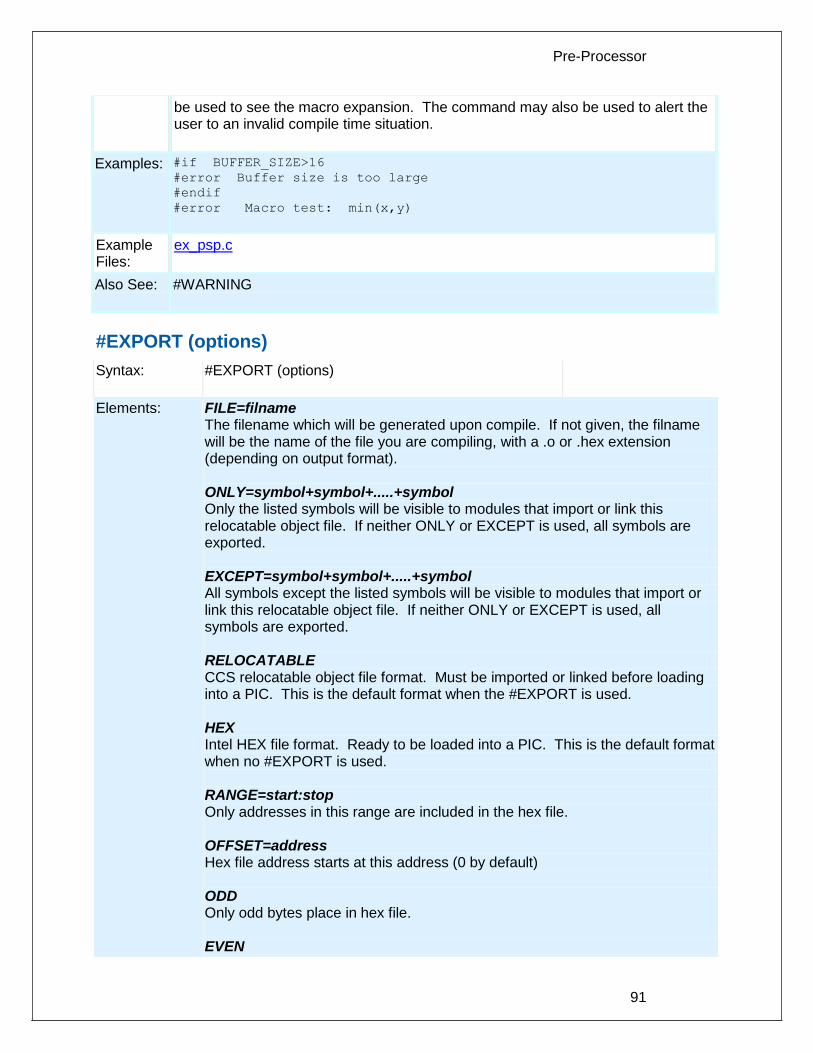
Pre-Processor
91
be used to see the macro expansion. The command may also be used to alert the user to an invalid compile time situation.
Examples: #if BUFFER_SIZE>16 #error Buffer size is too large
#endif
#error Macro test: min(x,y)
Example Files:
ex_psp.c
Also See: #WARNING
#EXPORT (options)
Syntax: #EXPORT (options)
Elements: FILE=filname The filename which will be generated upon compile. If not given, the filname will be the name of the file you are compiling, with a .o or .hex extension (depending on output format). ONLY=symbol+symbol+.....+symbol Only the listed symbols will be visible to modules that import or link this relocatable object file. If neither ONLY or EXCEPT is used, all symbols are exported. EXCEPT=symbol+symbol+.....+symbol All symbols except the listed symbols will be visible to modules that import or link this relocatable object file. If neither ONLY or EXCEPT is used, all symbols are exported. RELOCATABLE CCS relocatable object file format. Must be imported or linked before loading into a PIC. This is the default format when the #EXPORT is used. HEX Intel HEX file format. Ready to be loaded into a PIC. This is the default format when no #EXPORT is used. RANGE=start:stop Only addresses in this range are included in the hex file. OFFSET=address Hex file address starts at this address (0 by default) ODD Only odd bytes place in hex file. EVEN

PCD
92
Only even bytes placed in hex file.
Purpose: This directive will tell the compiler to either generate a relocatable object file or a stand-alone HEX binary. A relocatable object file must be linked into your application, while a stand-alone HEX binary can be programmed directly into the PIC. The command line compiler and the PCW IDE Project Manager can also be used to compile/link/build modules and/or projects. Multiple #EXPORT directives may be used to generate multiple hex files. this may be used for 8722 like devices with external memory.
Examples: #EXPORT(RELOCATABLE, ONLY=TimerTask)
void TimerFunc1(void) { /* some code */ }
void TimerFunc2(void) { /* some code */ }
void TimerFunc3(void) { /* some code */ }
void TimerTask(void)
{
TimerFunc1();
TimerFunc2();
TimerFunc3();
}
/*
This source will be compiled into a relocatable object, but the
object this is being linked to can only see TimerTask()
*/
Example Files: None
See Also:
#IMPORT, #MODULE, Invoking the Command Line Compiler, Multiple Compilation Unit
__FILENAME__
Syntax: __FILENAME__
Elements: None
Purpose: The pre-processor identifier is replaced at compile time with the filename of the file being compiled.
Examples: if(index>MAX_ENTRIES)
printf("Too many entries, source file: "
__FILENAME__ " at line " __LINE__ "\r\n");
Example Files:
None
Also See: _ _ line_ _
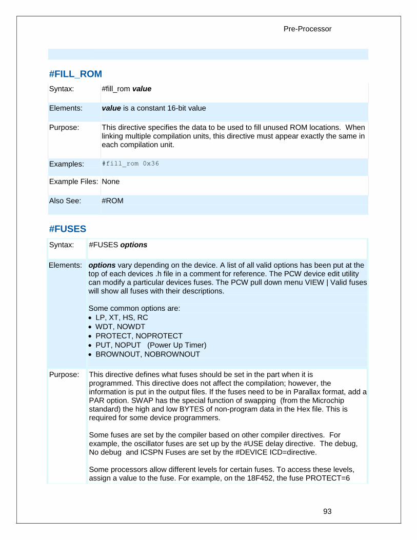
Pre-Processor
93
#FILL_ROM
Syntax: #fill_rom value
Elements: value is a constant 16-bit value
Purpose: This directive specifies the data to be used to fill unused ROM locations. When linking multiple compilation units, this directive must appear exactly the same in each compilation unit.
Examples: #fill_rom 0x36
Example Files: None
Also See: #ROM
#FUSES
Syntax: #FUSES options
Elements: options vary depending on the device. A list of all valid options has been put at the top of each devices .h file in a comment for reference. The PCW device edit utility can modify a particular devices fuses. The PCW pull down menu VIEW | Valid fuses will show all fuses with their descriptions. Some common options are:
LP, XT, HS, RC
WDT, NOWDT
PROTECT, NOPROTECT
PUT, NOPUT (Power Up Timer)
BROWNOUT, NOBROWNOUT
Purpose: This directive defines what fuses should be set in the part when it is programmed. This directive does not affect the compilation; however, the information is put in the output files. If the fuses need to be in Parallax format, add a PAR option. SWAP has the special function of swapping (from the Microchip standard) the high and low BYTES of non-program data in the Hex file. This is required for some device programmers. Some fuses are set by the compiler based on other compiler directives. For example, the oscillator fuses are set up by the #USE delay directive. The debug, No debug and ICSPN Fuses are set by the #DEVICE ICD=directive. Some processors allow different levels for certain fuses. To access these levels, assign a value to the fuse. For example, on the 18F452, the fuse PROTECT=6
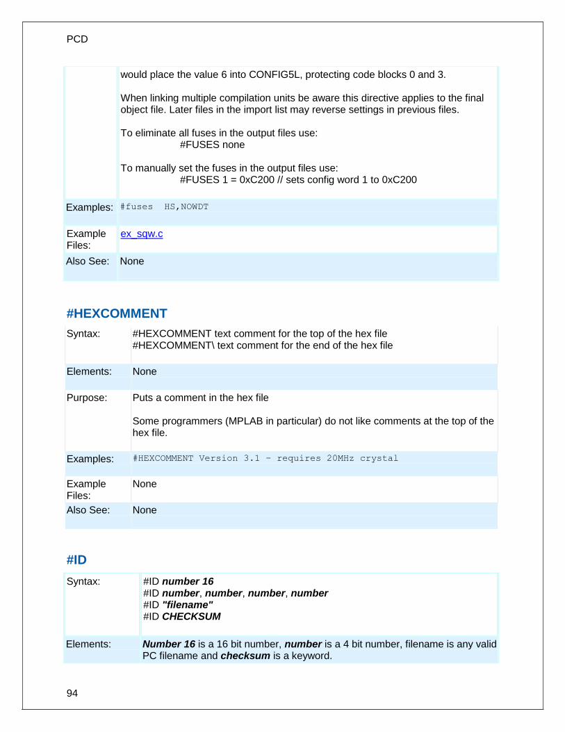
PCD
94
would place the value 6 into CONFIG5L, protecting code blocks 0 and 3. When linking multiple compilation units be aware this directive applies to the final object file. Later files in the import list may reverse settings in previous files. To eliminate all fuses in the output files use: #FUSES none To manually set the fuses in the output files use: #FUSES 1 = 0xC200 // sets config word 1 to 0xC200
Examples: #fuses HS,NOWDT
Example Files:
ex_sqw.c
Also See: None
#HEXCOMMENT
Syntax: #HEXCOMMENT text comment for the top of the hex file #HEXCOMMENT\ text comment for the end of the hex file
Elements: None
Purpose: Puts a comment in the hex file Some programmers (MPLAB in particular) do not like comments at the top of the hex file.
Examples: #HEXCOMMENT Version 3.1 – requires 20MHz crystal
Example Files:
None
Also See: None
#ID
Syntax: #ID number 16 #ID number, number, number, number #ID "filename" #ID CHECKSUM
Elements: Number 16 is a 16 bit number, number is a 4 bit number, filename is any valid PC filename and checksum is a keyword.

Pre-Processor
95
Purpose: This directive defines the ID word to be programmed into the part. This directive does not affect the compilation but the information is put in the output file. The first syntax will take a 16 -bit number and put one nibble in each of the four ID words in the traditional manner. The second syntax specifies the exact value to be used in each of the four ID words . When a filename is specified the ID is read from the file. The format must be simple text with a CR/LF at the end. The keyword CHECKSUM indicates the device checksum should be saved as the ID.
Examples: #id 0x1234
#id "serial.num"
#id CHECKSUM
Example Files: ex_cust.c
Also See: None
#IF exp #ELSE #ELIF #ENDIF
Syntax: #if expr code
#elif expr //Optional, any number may be used code #else //Optional code #endif
Elements: expr is an expression with constants, standard operators and/or preprocessor identifiers. Code is any standard c source code.
Purpose: The pre-processor evaluates the constant expression and if it is non-zero will process the lines up to the optional #ELSE or the #ENDIF.
Note: you may NOT use C variables in the #IF. Only preprocessor identifiers created via #define can be used. The preprocessor expression DEFINED(id) may be used to return 1 if the id is defined and 0 if it is not. == and != operators now accept a constant string as both operands. This allows for compile time comparisons and can be used with GETENV() when it returns a string result.

PCD
96
Examples: #if MAX_VALUE > 255
long value;
#else
int value;
#endif
#if getenv(“DEVICE”)==”PIC16F877”
//do something special for the PIC16F877
#endif
Example Files: ex_extee.c
Also See: #IFDEF, #IFNDEF, getenv()
#IFDEF #IFNDEF #ELSE #ELIF #ENDIF
Syntax: #IFDEF id code
#ELIF code #ELSE code #ENDIF #IFNDEF id code #ELIF code #ELSE code #ENDIF
Elements: id is a preprocessor identifier, code is valid C source code.
Purpose: This directive acts much like the #IF except that the preprocessor simply checks to see if the specified ID is known to the preprocessor (created with a #DEFINE). #IFDEF checks to see if defined and #IFNDEF checks to see if it is not defined.
Examples: #define debug // Comment line out for no debug
...
#ifdef DEBUG
printf("debug point a");
#endif
Example Files: ex_sqw.c
Also See: #IF

Pre-Processor
97
#IGNORE_WARNINGS
Syntax: #ignore_warnings ALL #IGNORE_WARNINGS NONE #IGNORE_WARNINGS warnings
Elements: warnings is one or more warning numbers separated by commas
Purpose: This function will suppress warning messages from the compiler. ALL indicates no warning will be generated. NONE indicates all warnings will be generated. If numbers are listed then those warnings are suppressed.
Examples: #ignore_warnings 203 while(TRUE) {
#ignore_warnings NONE
Example Files:
None
Also See: Warning messages
#IMPORT (options)
Syntax: #IMPORT (options)
Elements: FILE=filname The filename of the object you want to link with this compilation. ONLY=symbol+symbol+.....+symbol Only the listed symbols will imported from the specified relocatable object file. If neither ONLY or EXCEPT is used, all symbols are imported. EXCEPT=symbol+symbol+.....+symbol The listed symbols will not be imported from the specified relocatable object file. If neither ONLY or EXCEPT is used, all symbols are imported. RELOCATABLE CCS relocatable object file format. This is the default format when the #IMPORT is used. COFF COFF file format from MPASM, C18 or C30. HEX Imported data is straight hex data. RANGE=start:stop

PCD
98
Only addresses in this range are read from the hex file. LOCATION=id The identifier is made a constant with the start address of the imported data. SIZE=id The identifier is made a constant with the size of the imported data.
Purpose: This directive will tell the compiler to include (link) a relocatable object with this unit during compilation. Normally all global symbols from the specified file will be linked, but the EXCEPT and ONLY options can prevent certain symbols from being linked. The command line compiler and the PCW IDE Project Manager can also be used to compile/link/build modules and/or projects.
Examples: #IMPORT(FILE=timer.o, ONLY=TimerTask)
void main(void)
{
while(TRUE)
TimerTask();
}
/*
timer.o is linked with this compilation, but only TimerTask() is
visible in scope from this object.
*/
Example Files: None
See Also: #EXPORT, #MODULE, Invoking the Command Line Compiler, Multiple Compilation Unit
#INCLUDE
Syntax: #INCLUDE <filename> or #INCLUDE "filename"
Elements: filename is a valid PC filename. It may include normal drive and path information. A file with the extension ".encrypted" is a valid PC file. The standard compiler #INCLUDE directive will accept files with this extension and decrypt them as they are read. This allows include files to be distributed without releasing the source code.
Purpose: Text from the specified file is used at this point of the compilation. If a full path is not specified the compiler will use the list of directories specified for the project to search for the file. If the filename is in "" then the directory with the main source file is searched first. If the filename is in <> then the directory with the main source file is searched last.

Pre-Processor
99
Examples: #include <16C54.H>
#include <C:\INCLUDES\COMLIB\MYRS232.C>
Example Files: ex_sqw.c
Also See: None
#INLINE
Syntax: #INLINE
Elements: None
Purpose: Tells the compiler that the function immediately following the directive is to be implemented INLINE. This will cause a duplicate copy of the code to be placed everywhere the function is called. This is useful to save stack space and to increase speed. Without this directive the compiler will decide when it is best to make procedures INLINE.
Examples: #inline
swapbyte(int &a, int &b) {
int t;
t=a;
a=b;
b=t;
}
Example Files: ex_cust.c
Also See: #SEPARATE
#INT_xxxx
Syntax: #INT_AD Analog to digital conversion complete
#INT_ADOF Analog to digital conversion timeout
#INT_BUSCOL Bus collision
#INT_BUSCOL2 Bus collision 2 detected
#INT_BUTTON Pushbutton
#INT_CANERR An error has occurred in the CAN module
#INT_CANIRX An invalid message has occurred on the CAN bus

PCD
100
#INT_CANRX0 CAN Receive buffer 0 has received a new message
#INT_CANRX1 CAN Receive buffer 1 has received a new message
#INT_CANTX0 CAN Transmit buffer 0 has completed transmission
#INT_CANTX1 CAN Transmit buffer 0 has completed transmission
#INT_CANTX2 CAN Transmit buffer 0 has completed transmission
#INT_CANWAKE Bus Activity wake-up has occurred on the CAN bus
#INT_CCP1 Capture or Compare on unit 1
#INT_CCP2 Capture or Compare on unit 2
#INT_CCP3 Capture or Compare on unit 3
#INT_CCP4 Capture or Compare on unit 4
#INT_CCP5 Capture or Compare on unit 5
#INT_COMP Comparator detect
#INT_COMP0 Comparator 0 detect
#INT_COMP1 Comparator 1 detect
#INT_COMP2 Comparator 2 detect
#INT_CR Cryptographic activity complete
#INT_EEPROM Write complete
#INT_ETH Ethernet module interrupt
#INT_EXT External interrupt
#INT_EXT1 External interrupt #1
#INT_EXT2 External interrupt #2
#INT_EXT3 External interrupt #3
#INT_I2C I2C interrupt (only on 14000)
#INT_IC1 Input Capture #1
#INT_IC2QEI Input Capture 2 / QEI Interrupt
#IC3DR Input Capture 3 / Direction Change Interrupt
#INT_LCD LCD activity
#INT_LOWVOLT Low voltage detected
#INT_LVD Low voltage detected
#INT_OSC_FAIL System oscillator failed
#INT_OSCF System oscillator failed
#INT_PMP Parallel Master Port interrupt
#INT_PSP Parallel Slave Port data in
#INT_PWMTB PWM Time Base

Pre-Processor
101
#INT_RA Port A any change on A0_A5
#INT_RB Port B any change on B4-B7
#INT_RC Port C any change on C4-C7
#INT_RDA RS232 receive data available
#INT_RDA0 RS232 receive data available in buffer 0
#INT_RDA1 RS232 receive data available in buffer 1
#INT_RDA2 RS232 receive data available in buffer 2
#INT_RTCC Timer 0 (RTCC) overflow
#INT_SPP Streaming Parallel Port Read/Write
#INT_SSP SPI or I2C activity
#INT_SSP2 SPI or I2C activity for Port 2
#INT_TBE RS232 transmit buffer empty
#INT_TBE0 RS232 transmit buffer 0 empty
#INT_TBE1 RS232 transmit buffer 1 empty
#INT_TBE2 RS232 transmit buffer 2 empty
#INT_TIMER0 Timer 0 (RTCC) overflow
#INT_TIMER1 Timer 1 overflow
#INT_TIMER2 Timer 2 overflow
#INT_TIMER3 Timer 3 overflow
#INT_TIMER4 Timer 4 overflow
#INT_TIMER5 Timer 5 overflow
#INT_ULPWU Ultra-low power wake up interrupt
#INT_USB Universal Serial Bus activity
Note many more #INT_ options are available on specific chips. Check the devices .h file for a full list for a given chip.
Elements: None
Purpose: These directives specify the following function is an interrupt function. Interrupt functions may not have any parameters. Not all directives may be used with all parts. See the devices .h file for all valid interrupts for the part or in PCW use the pull down VIEW | Valid Ints The compiler will generate code to jump to the function when the interrupt is detected. It will generate code to save and restore the machine state, and will clear the interrupt flag. To prevent the flag from being cleared add NOCLEAR after the #INT_xxxx. The application program must call ENABLE_INTERRUPTS(INT_xxxx) to initially activate the interrupt along with the

PCD
102
ENABLE_INTERRUPTS(GLOBAL) to enable interrupts. The keywords HIGH and FAST may be used with the PCH compiler to mark an interrupt as high priority. A high-priority interrupt can interrupt another interrupt handler. An interrupt marked FAST is performed without saving or restoring any registers. You should do as little as possible and save any registers that need to be saved on your own. Interrupts marked HIGH can be used normally. See #DEVICE for information on building with high-priority interrupts. A summary of the different kinds of PIC18 interrupts: #INT_xxxx Normal (low priority) interrupt. Compiler saves/restores key registers. This interrupt will not interrupt any interrupt in progress. #INT_xxxx FAST High priority interrupt. Compiler DOES NOT save/restore key registers. This interrupt will interrupt any normal interrupt in progress. Only one is allowed in a program. #INT_xxxx HIGH High priority interrupt. Compiler saves/restores key registers. This interrupt will interrupt any normal interrupt in progress. #INT_xxxx NOCLEAR The compiler will not clear the interrupt. The user code in the function should call clear_interrput( ) to clear the interrupt in this case. #INT_GLOBAL Compiler generates no interrupt code. User function is located at address 8 for user interrupt handling. Some interrupts shown in the devices header file are only for the enable/disable interrupts. For example, INT_RB3 may be used in enable/interrupts to enable pin B3. However, the interrupt handler is #INT_RB. Similarly INT_EXT_L2H sets the interrupt edge to falling and the handler is #INT_EXT.
Examples: #int_ad adc_handler() {
adc_active=FALSE;
}
#int_rtcc noclear
isr() {
...
}
Example Files:
See ex_sisr.c and ex_stwt.c for full example programs.
Also See: enable_interrupts(), disable_interrupts(), #INT_DEFAULT, #INT_GLOBAL, #PRIORITY

Pre-Processor
103
#INT_DEFAULT
Syntax: #INT_DEFAULT
Elements: None
Purpose: The following function will be called if the PIC® triggers an interrupt and none of the interrupt flags are set. If an interrupt is flagged, but is not the one triggered, the #INT_DEFAULT function will get called.
Examples: #int_default default_isr() {
printf("Unexplained interrupt\r\n");
}
Example Files:
None
Also See: #INT_xxxx, #INT_global
#INT_GLOBAL
Syntax: #INT_GLOBAL
Elements: None
Purpose: This directive causes the following function to replace the compiler interrupt dispatcher. The function is normally not required and should be used with great caution. When used, the compiler does not generate start-up code or clean-up code, and does not save the registers.
Examples: #int_global isr() { // Will be located at location 4 for PIC16 chips.
#asm
bsf isr_flag
retfie
#endasm
}
Example Files:
ex_glint.c
Also See: #INT_xxxx

PCD
104
__LINE__
Syntax: __line__
Elements: None
Purpose: The pre-processor identifier is replaced at compile time with line number of the file being compiled.
Examples: if(index>MAX_ENTRIES)
printf("Too many entries, source file: "
__FILE__" at line " __LINE__ "\r\n");
Example Files:
assert.h
Also See: _ _ file_ _
#LIST
Syntax: #LIST
Elements: None
Purpose: #LIST begins inserting or resumes inserting source lines into the .LST file after a #NOLIST.
Examples: #NOLIST // Don't clutter up the list file
#include <cdriver.h>
#LIST
Example Files:
16c74.h
Also See: #NOLIST
#LINE
Syntax: #LINE number file name
Elements: Number is non-negative decimal integer. File name is optional.
Purpose: The C pre-processor informs the C Compiler of the location in your source code. This code is simply used to change the value of _LINE_ and _FILE_ variables.

Pre-Processor
105
Examples: 1. void main(){ #line 10 // specifies the line number that
// should be reported for
// the following line of input
2. #line 7 "hello.c"
// line number in the source file
// hello.c and it sets the
// line 7 as current line
// and hello.c as current file
Example Files:
None
Also See: None
#LOCATE
Syntax: #LOCATE id=x
Elements: id is a C variable, x is a constant memory address
Purpose: #LOCATE allocates a C variable to a specified address. If the C variable was not previously defined, it will be defined as an INT8. A special form of this directive may be used to locate all A functions local variables starting at a fixed location. Use: #LOCATE Auto = address This directive will place the indirected C variable at the requested address.
Examples: // This will locate the float variable at 50-53
// and C will not use this memory for other
// variables automatically located.
float x;
#locate x=0x 50
Example Files:
ex_glint.c
Also See: #BYTE, #BIT, #RESERVE, #WORD
#MODULE
Syntax: #MODULE
Elements: None

PCD
106
Purpose: All global symbols created from the #MODULE to the end of the file will only be visible within that same block of code (and files #INCLUDE within that block). This may be used to limit the scope of global variables and functions within include files. This directive also applies to pre-processor #defines. Note: The extern and static data qualifiers can also be used to denote scope of variables and functions as in the standard C methodology. #MODULE does add some benefits in that pre-processor #DEFINE can be given scope, which cannot normally be done in standard C methodology.
Examples: int GetCount(void); void SetCount(int newCount);
#MODULE
int g_count;
#define G_COUNT_MAX 100
int GetCount(void) {return(g_count);}
void SetCount(int newCount) {
if (newCount>G_COUNT_MAX)
newCount=G_COUNT_MAX;
g_count=newCount;
}
/*
the functions GetCount() and SetCount() have global scope, but the
variable g_count and the #define G_COUNT_MAX only has scope to this
file.
*/
Example Files:
None
See Also: #EXPORT, Invoking the Command Line Compiler, Multiple Compilation Unit
#NOLIST
Syntax: #NOLIST
Elements: None
Purpose: Stops inserting source lines into the .LST file (until a #LIST)
Examples: #NOLIST // Don't clutter up the list file
#include <cdriver.h>
#LIST
Example Files:
16c74.h
Also See: #LIST

Pre-Processor
107
#OCS
Syntax: #OCS x
Elements: x is the clock's speed and can be 1 Hz to 100 MHz.
Purpose: Used instead of the #use delay(clock = x)
Examples: #include <18F4520.h>
#device ICD=TRUE
#OCS 20 MHz
#use rs232(debugger)
void main(){
-------;
}
Example Files:
None
Also See: #USE DELAY
#OPT
Syntax: #OPT n
Elements: All Devices: n is the optimization level 1-11 or by using the word "compress" for PIC18 and Enhanced PIC16 families.
Purpose: The optimization level is set with this directive. This setting applies to the entire program and may appear anywhere in the file. The PCW default is 9 for normal. When Compress is specified the optimization is set to an extreme level that causes a very tight rom image, the code is optimized for space, not speed. Debugging with this level my be more difficult.
Examples: #opt 5
Example Files:
None
Also See: None
#ORG
Syntax: #ORG start, end or
#ORG segment or

PCD
108
#ORG start, end { } or
#ORG start, end auto=0 #ORG start,end DEFAULT or #ORG DEFAULT
Elements: start is the first ROM location (word address) to use, end is the last ROM location, segment is the start ROM location from a previous #ORG
Purpose: This directive will fix the following function, constant or ROM declaration into a specific ROM area. End may be omitted if a segment was previously defined if you only want to add another function to the segment. Follow the ORG with a { } to only reserve the area with nothing inserted by the compiler. The RAM for a ORG'd function may be reset to low memory so the local variables and scratch variables are placed in low memory. This should only be used if the ORG'd function will not return to the caller. The RAM used will overlap the RAM of the main program. Add a AUTO=0 at the end of the #ORG line. If the keyword DEFAULT is used then this address range is used for all functions user and compiler generated from this point in the file until a #ORG DEFAULT is encountered (no address range). If a compiler function is called from the generated code while DEFAULT is in effect the compiler generates a new version of the function within the specified address range.
#ORG may be used to locate data in ROM. #ORG may be used to locate data in ROM. Because CONSTANT are implemented as functions the #ORG should proceed the CONSTANT and needs a start and end address. For a ROM declaration only the start address should be specified. When linking multiple compilation units be aware this directive applies to the final object file. It is an error if any #ORG overlaps between files unless the #ORG matches exactly.
Examples: #ORG 0x1E00, 0x1FFF
MyFunc() {
//This function located at 1E00
}
#ORG 0x1E00
Anotherfunc(){
// This will be somewhere 1E00-1F00
}
#ORG 0x800, 0x820 {}
//Nothing will be at 800-820

Pre-Processor
109
#ORG 0x1B80
ROM int32 seridl_N0=12345;
#ORG 0x1C00, 0x1C0F
CHAR CONST ID[10}= {"123456789"};
//This ID will be at 1C00
//Note some extra code will
//proceed the 123456789
#ORG 0x1F00, 0x1FF0
Void loader (){
.
.
.
}
Example Files: loader.c
Also See: #ROM
#PIN_SELECT
Syntax: #PIN_SELECT function=pin_xx
Elements: function is the Microchip defined pin function name, such as: U1RX (UART1 receive), INT1 (external interrupt 1), T2CK (timer 2 clock), IC1 (input capture 1), OC1 (output capture 1).
INT1 External Interrupt 1
INT2 External Interrupt 2
INT3 External Interrupt 3
T0CK Timer0 External Clock
T3CK Timer3 External Clock
CCP1 Input Capture 1
CCP2 Input Capture 2
T1G Timer1 Gate Input
T3G Timer3 Gate Input
U2RX EUSART2 Asynchronous Receive/Synchronous Receive (also named: RX2)
U2CK EUSART2 Asynchronous Clock Input

PCD
110
SDI2 SPI2 Data Input
SCK2IN SPI2 Clock Input
SS2IN SPI2 Slave Select Input
FLT0 PWM Fault Input
T0CKI Timer0 External Clock Input
T3CKI Timer3 External Clock Input
RX2 EUSART2 Asynchronous Transmit/Asynchronous Clock Output (also named: TX2)
NULL NULL
C1OUT Comparator 1 Output
C2OUT Comparator 2 Output
U2TX EUSART2 Asynchronous Transmit/ Asynchronous Clock Output (also named: TX2)
U2DT EUSART2 Synchronous Transmit (also named: DT2)
SDO2 SPI2 Data Output
SCK2OUT SPIC2 Clock Output
SS2OUT SPI2 Slave Select Output
ULPOUT Ultra Low-Power Wake-Up Event
P1A ECCP1 Compare or PWM Output Channel A
P1B ECCP1 Enhanced PWM Output, Channel B
P1C ECCP1 Enhanced PWM Output, Channel C
P1D ECCP1 Enhanced PWM Output, Channel D

Pre-Processor
111
P2A ECCP2 Compare or PWM Output Channel A
P2B ECCP2 Enhanced PWM Output, Channel B
P2C ECCP2 Enhanced PWM Output, Channel C
P2D ECCP1 Enhanced PWM Output, Channel D
TX2 EUSART2 Asynchronous Transmit/Asynchronous Clock Output (also named: TX2)
DT2 EUSART2 Synchronous Transmit (also named: U2DT)
SCK2 SPI2 Clock Output
SSDMA SPI DMA Slave Select
pin_xx is the CCS provided pin definition. For example: PIN_C7, PIN_B0, PIN_D3, etc.
Purpose: When using PPS chips a #PIN_SELECT must be appear before these peripherals can be used or referenced.
Examples: #pin_select U1TX=PIN_C6
#pin_select U1RX=PIN_C7
#pin_select INT1=PIN_B0
Example Files:
None
Also See: None
__PCB__
Syntax: __PCB__
Elements: None
Purpose: The PCB compiler defines this pre-processor identifier. It may be used to

PCD
112
determine if the PCB compiler is doing the compilation.
Examples: #ifdef __pcb__
#device PIC16c54
#endif
Example Files:
ex_sqw.c
Also See: __PCM__, __PCH__
__ PCM __
Syntax: __PCM__
Elements: None
Purpose: The PCM compiler defines this pre-processor identifier. It may be used to determine if the PCM compiler is doing the compilation.
Examples: #ifdef __pcm__
#device PIC16c71
#endif
Example Files:
ex_sqw.c
Also See: __PCB__, __PCH__
__ PCH __
Syntax: __PCH__
Elements: None
Purpose: The PCH compiler defines this pre-processor identifier. It may be used to determine if the PCH compiler is doing the compilation.
Examples: #ifdef _ _ PCH _ _
#device PIC18C452
#endif
Example Files:
ex_sqw.c

Pre-Processor
113
Also See: __PCB__, __PCM__
#PRAGMA
Syntax: #PRAGMA cmd
Elements: cmd is any valid preprocessor directive.
Purpose: This directive is used to maintain compatibility between C compilers. This compiler will accept this directive before any other pre-processor command. In no case does this compiler require this directive.
Examples: #pragma device PIC16C54
Example Files:
ex_cust.c
Also See: None
#PRIORITY
Syntax: #PRIORITY ints
Elements: ints is a list of one or more interrupts separated by commas. export makes the functions generated from this directive available to other compilation units within the link.
Purpose: The priority directive may be used to set the interrupt priority. The highest priority items are first in the list. If an interrupt is active it is never interrupted. If two interrupts occur at around the same time then the higher one in this list will be serviced first. When linking multiple compilation units be aware only the one in the last compilation unit is used.
Examples: #priority rtcc,rb
Example Files:
None
Also See: #INT_xxxx
#PROFILE

PCD
114
Syntax: #profile options
Elements:
options may be one of the following:
functions Profiles the start/end of functions and all profileout() messages.
functions, parameters Profiles the start/end of functions, parameters sent to functions, and all
profileout() messages.
profileout Only profile profilout() messages.
paths Profiles every branch in the code.
off Disable all code profiling.
on Re-enables the code profiling that was previously disabled with a #profile
off command. This will use the last options before disabled with the off
command.
Purpose: Large programs on the microcontroller may generate lots of profile data, which may make it difficult to debug or follow. By using #profile the user can dynamically control which points of the program are being profiled, and limit data to what is relevant to the user.
Examples:
#profile off
void BigFunction(void)
{
// BigFunction code goes here.
// Since #profile off was called above,
// no profiling will happen even for other
// functions called by BigFunction().
}
#profile on
Example Files:
ex_profile.c
Also See:
#use profile(), profileout(), Code Profile overview
#RESERVE
Syntax: #RESERVE address or #RESERVE address, address, address or
#RESERVE start:end
Elements: address is a RAM address, start is the first address and end is the last address
Purpose: This directive allows RAM locations to be reserved from use by the

Pre-Processor
115
compiler. #RESERVE must appear after the #DEVICE otherwise it will have no effect. When linking multiple compilation units be aware this directive applies to the final object file.
Examples: #DEVICE PIC16C74
#RESERVE 0x60:0X6f
Example Files:
ex_cust.c
Also See: #ORG
#ROM
Syntax: #ROM address = {list}
#ROM type address = {list}
Elements: address is a ROM word address, list is a list of words separated by commas
Purpose: Allows the insertion of data into the .HEX file. In particular, this may be used to program the '84 data EEPROM, as shown in the following example. Note that if the #ROM address is inside the program memory space, the directive creates a segment for the data, resulting in an error if a #ORG is over the same area. The #ROM data will also be counted as used program memory space. The type option indicates the type of each item, the default is 16 bits. Using char as the type treats each item as 7 bits packing 2 chars into every pcm 14-bit word. When linking multiple compilation units be aware this directive applies to the final object file. Some special forms of this directive may be used for verifying program memory: #ROM address = checksum This will put a value at address such that the entire program memory will sum to 0x1248 #ROM address = crc16 This will put a value at address that is a crc16 of all the program memory except the specified address #ROM address = crc8 This will put a value at address that is a crc16 of all the program memory except the specified address
Examples: #rom getnev ("EEPROM_ADDRESS")={1,2,3,4,5,6,7,8} #rom int8 0x1000={"(c)CCS, 2010"}

PCD
116
Example Files:
None
Also See: #ORG
#SEPARATE
Syntax: #SEPARATE
Elements: None
Purpose: Tells the compiler that the procedure IMMEDIATELY following the directive is to be implemented SEPARATELY. This is useful to prevent the compiler from automatically making a procedure INLINE. This will save ROM space but it does use more stack space. The compiler will make all procedures marked SEPARATE, separate, as requested, even if there is not enough stack space to execute.
Examples: #separate
swapbyte (int *a, int *b) {
int t;
t=*a;
*a=*b;
*b=t;
}
Example Files: ex_cust.c
Also See: #INLINE
#SERIALIZE
Syntax: #SERIALIZE(id=xxx, next="x" | file="filename.txt" " | listfile="filename.txt", "prompt="text", log="filename.txt") - or #SERIALIZE(dataee=x, binary=x, next="x" | file="filename.txt" | listfile="filename.txt", prompt="text", log="filename.txt")
Elements: id=xxx - Specify a C CONST identifier, may be int8, int16, int32 or char array Use in place of id parameter, when storing serial number to EEPROM: dataee=x - The address x is the start address in the data EEPROM. binary=x - The integer x is the number of bytes to be written to address specified. -or- string=x - The integer x is the number of bytes to be written to address

Pre-Processor
117
specified. Use only one of the next three options: file="filename.txt" - The file x is used to read the initial serial number from, and this file is updated by the ICD programmer. It is assumed this is a one line file with the serial number. The programmer will increment the serial number. listfile="filename.txt" - The file x is used to read the initial serial number from, and this file is updated by the ICD programmer. It is assumed this is a file one serial number per line. The programmer will read the first line then delete that line from the file. next="x" - The serial number X is used for the first load, then the hex file is updated to increment x by one. Other optional parameters: prompt="text" - If specified the user will be prompted for a serial number on each load. If used with one of the above three options then the default value the user may use is picked according to the above rules. log=xxx - A file may optionally be specified to keep a log of the date, time, hex file name and serial number each time the part is programmed. If no id=xxx is specified then this may be used as a simple log of all loads of the hex file.
Purpose: Assists in making serial numbers easier to implement when working with CCS ICD units. Comments are inserted into the hex file that the ICD software interprets.
Examples: //Prompt user for serial number to be placed
//at address of serialNumA
//Default serial number = 200int8int8 const serialNumA=100;
#serialize(id=serialNumA,next="200",prompt="Enter the serial
number")
//Adds serial number log in seriallog.txt
#serialize(id=serialNumA,next="200",prompt="Enter the serial
number", log="seriallog.txt")
//Retrieves serial number from serials.txt
#serialize(id=serialNumA,listfile="serials.txt")
//Place serial number at EEPROM address 0, reserving 1 byte
#serialize(dataee=0,binary=1,next="45",prompt="Put in Serial
number")
//Place string serial number at EEPROM address 0, reserving 2
bytes
#serialize(dataee=0, string=2,next="AB",prompt="Put in Serial
number")
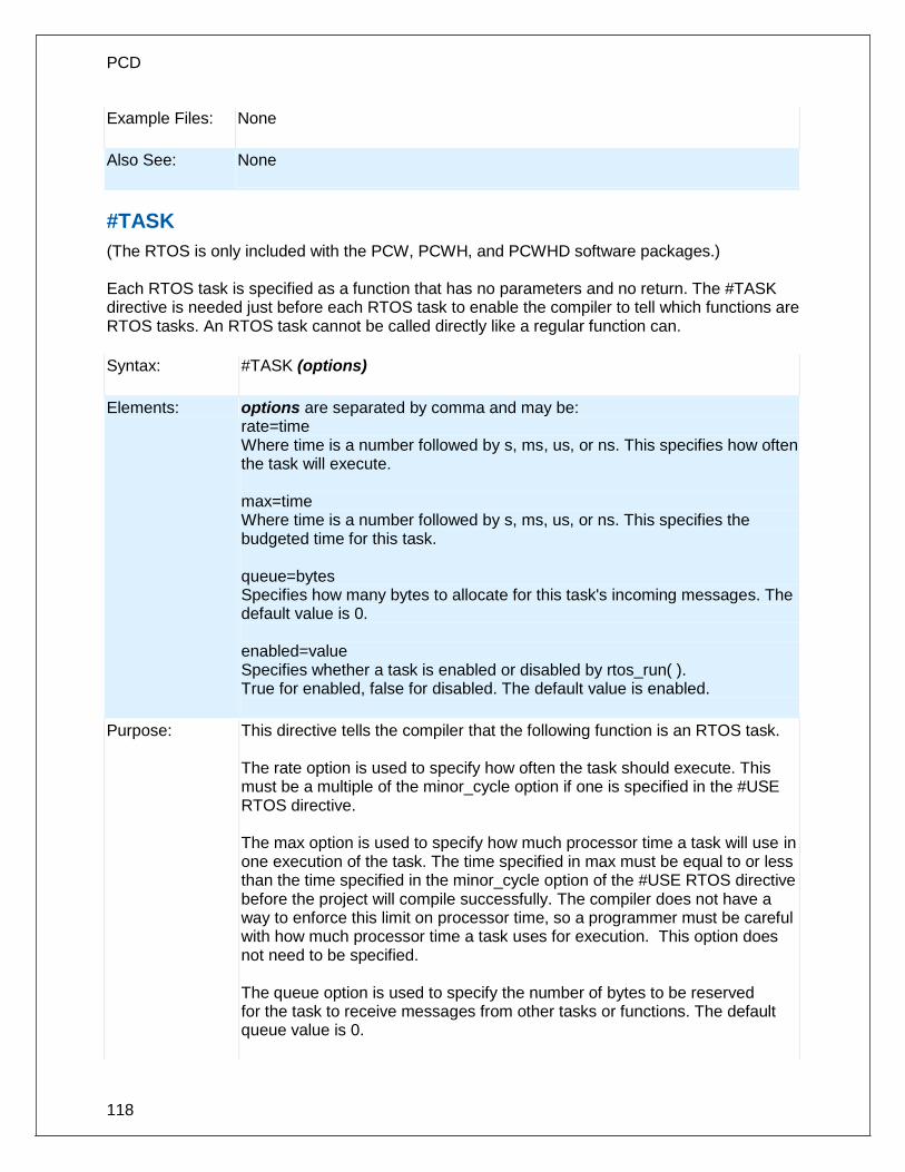
PCD
118
Example Files: None
Also See: None
#TASK
(The RTOS is only included with the PCW, PCWH, and PCWHD software packages.) Each RTOS task is specified as a function that has no parameters and no return. The #TASK directive is needed just before each RTOS task to enable the compiler to tell which functions are RTOS tasks. An RTOS task cannot be called directly like a regular function can.
Syntax: #TASK (options)
Elements: options are separated by comma and may be: rate=time Where time is a number followed by s, ms, us, or ns. This specifies how often the task will execute. max=time Where time is a number followed by s, ms, us, or ns. This specifies the budgeted time for this task. queue=bytes Specifies how many bytes to allocate for this task's incoming messages. The default value is 0. enabled=value Specifies whether a task is enabled or disabled by rtos_run( ). True for enabled, false for disabled. The default value is enabled.
Purpose: This directive tells the compiler that the following function is an RTOS task. The rate option is used to specify how often the task should execute. This must be a multiple of the minor_cycle option if one is specified in the #USE RTOS directive. The max option is used to specify how much processor time a task will use in one execution of the task. The time specified in max must be equal to or less than the time specified in the minor_cycle option of the #USE RTOS directive before the project will compile successfully. The compiler does not have a way to enforce this limit on processor time, so a programmer must be careful with how much processor time a task uses for execution. This option does not need to be specified. The queue option is used to specify the number of bytes to be reserved for the task to receive messages from other tasks or functions. The default queue value is 0.

Pre-Processor
119
Examples: #task(rate=1s, max=20ms, queue=5)
Also See: #USE RTOS
__ TIME __
Syntax: __TIME__
Elements: None
Purpose: This pre-processor identifier is replaced at compile time with the time of the compile in the form: "hh:mm:ss"
Examples: printf("Software was compiled on ");
printf(__TIME__);
Example Files:
None
Also See: None
#TYPE
Syntax: #TYPE standard-type=size #TYPE default=area #TYPE unsigned #TYPE signed
Elements: standard-type is one of the C keywords short, int, long, or default size is 1,8,16, or 32 area is a memory region defined before the #TYPE using the addressmod directive
Purpose: By default the compiler treats SHORT as one bit , INT as 8 bits, and LONG as 16 bits. The traditional C convention is to have INT defined as the most efficient size for the target processor. This is why it is 8 bits on the PIC ® . In order to help with code compatibility a #TYPE directive may be used to allow these types to be changed. #TYPE can redefine these keywords. Note that the commas are optional. Since #TYPE may render some sizes inaccessible (like a one bit int in the above) four keywords representing the four ints may always be used: INT1, INT8, INT16, and INT32. Be warned CCS example programs and include files may not work right if you use #TYPE in your program. This directive may also be used to change the default RAM area used for variable storage. This is done by specifying default=area where area is a addressmod

PCD
120
address space. When linking multiple compilation units be aware this directive only applies to the current compilation unit. The #TYPE directive allows the keywords UNSIGNED and SIGNED to set the default data type.
Examples: #TYPE SHORT= 8 , INT= 16 , LONG= 32
#TYPE default=area
addressmod (user_ram_block, 0x100, 0x1FF);
#type default=user_ram_block // all variable declarations
// in this area will be in
// 0x100-0x1FF
#type default= // restores memory allocation
// back to normal
#TYPE SIGNED
...
void main()
{
int variable1; // variable1 can only take values from -128 to 127
...
...
}
Example Files:
ex_cust.c
Also See: None
#UNDEF
Syntax: #UNDEF id
Elements: id is a pre-processor id defined via #DEFINE
Purpose: The specified pre-processor ID will no longer have meaning to the pre-processor.
Examples: #if MAXSIZE<100
#undef MAXSIZE
#define MAXSIZE 100
#endif

Pre-Processor
121
Example Files:
None
Also See: #DEFINE
#USE CAPTURE
Syntax: #USE CAPTURE(options)
Elements: ICx/CCPx Which CCP/Input Capture module to us. INPUT = PIN_xx Specifies which pin to use. Useful for device with remappable pins, this will cause compiler to automatically assign pin to peripheral. TIMER=x Specifies the timer to use with capture unit. If not specified default to timer 1 for PCM and PCH compilers and timer 3 for PCD compiler. TICK=x The tick time to setup the timer to. If not specified it will be set to fastest as possible or if same timer was already setup by a previous stream it will be set to that tick time. If using same timer as previous stream and different tick time an error will be generated. FASTEST Use instead of TICK=x to set tick time to fastest as possible. SLOWEST Use instead of TICK=x to set tick time to slowest as possible. CAPTURE_RISING Specifies the edge that timer value is captured on. Defaults to CAPTURE_RISING. CAPTURE_FALLING Specifies the edge that timer value is captured on. Defaults to CAPTURE_RISING. CAPTURE_BOTH PCD only. Specifies the edge that timer value is captured on. Defaults to CAPTURE_RISING. PRE=x Specifies number of rising edges before capture event occurs. Valid options are 1, 4 and 16, default to 1 if not specified. Options 4 and 16 are only valid when using

PCD
122
CAPTURE_RISING, will generate an error is used with CAPTURE_FALLING or CAPTURE_BOTH. ISR=x STREAM=id Associates a stream identifier with the capture module. The identifier may be used in functions like get_capture_time(). DEFINE=id Creates a define named id which specifies the number of capture per second. Default define name if not specified is CAPTURES_PER_SECOND. Define name must start with an ASCII letter 'A' to 'Z', an ASCII letter 'a' to 'z' or an ASCII underscore ('_').
Purpose: This directive tells the compiler to setup an input capture on the specified pin using the specified settings. The #USE DELAY directive must appear before this directive can be used. This directive enables use of built-in functions such as get_capture_time() and get_capture_event().
Examples: #USE CAPTURE(INPUT=PIN_C2,CAPTURE_RISING,TIMER=1,FASTEST)
Example Files:
None.
Also See: get_capture_time(), get_capture_event()
#USE DELAY
Syntax: #USE DELAY (options))
Elements: Options may be any of the following separated by commas: clock=speed speed is a constant 1-100000000 (1 hz to 100 mhz). This number can contains commas. This number also supports the following denominations: M, MHZ, K, KHZ. This specifies the clock the CPU runs at. Depending on the PIC this is 2 or 4 times the instruction rate. This directive is not needed if the following type=speed is used and there is no frequency multiplication or division. type=speed type defines what kind of clock you are using, and the following values are valid: oscillator, osc (same as oscillator), crystal, xtal (same as crystal), internal, int (same as internal) or rc. The compiler will automatically set the oscillator configuration bits based upon your defined type. If you specified internal, the compiler will also automatically set the internal oscillator to the defined speed. Configuration fuses are modified when this option is used. Speed is the input frequency. restart_wdt will restart the watchdog timer on every delay_us() and delay_ms() use. clock_out when used with the internal or oscillator types this enables the clockout

Pre-Processor
123
pin to output the clock. fast_start some chips allow the chip to begin execution using an internal clock until the primary clock is stable. lock some chips can prevent the oscillator type from being changed at run time by the software. USB or USB_FULL for devices with a built-in USB peripheral. When used with the type=speed option the compiler will set the correct configuration bits for the USB peripheral to operate at Full-Speed. USB_LOW for devices with a built-in USB peripheral. When used with the type=speed option the compiler will set the correct configuration bits for the USB peripheral to operate at Low-Speed.
Also See: delay_ms(), delay_us()
#USE DYNAMIC_MEMORY
Syntax: #USE DYNAMIC_MEMORY
Elements: None
Purpose: This pre-processor directive instructs the compiler to create the _DYNAMIC_HEAD object. _DYNAMIC_HEAD is the location where the first free space is allocated.
Examples: #USE DYNAMIC_MEMORY
void main ( ){
}
Example Files:
ex_malloc.c
Also See: None
#USE FAST_IO
Syntax: #USE FAST_IO (port)
Elements: port is A, B, C, D, E, F, G, H, J or ALL
Purpose: Affects how the compiler will generate code for input and output instructions that follow. This directive takes effect until another #use xxxx_IO directive is

PCD
124
encountered. The fast method of doing I/O will cause the compiler to perform I/O without programming of the direction register. The compiler's default operation is the opposite of this command, the direction I/O will be set/cleared on each I/O operation. The user must ensure the direction register is set correctly via set_tris_X(). When linking multiple compilation units be aware this directive only applies to the current compilation unit.
Examples: #use fast_io(A)
Example Files:
ex_cust.c
Also See: #USE FIXED_IO, #USE STANDARD_IO, set_tris_X() , General Purpose I/O
#USE FIXED_IO
Syntax: #USE FIXED_IO (port_outputs=pin, pin?)
Elements: port is A-G, pin is one of the pin constants defined in the devices .h file.
Purpose: This directive affects how the compiler will generate code for input and output instructions that follow. This directive takes effect until another #USE XXX_IO directive is encountered. The fixed method of doing I/O will cause the compiler to generate code to make an I/O pin either input or output every time it is used. The pins are programmed according to the information in this directive (not the operations actually performed). This saves a byte of RAM used in standard I/O. When linking multiple compilation units be aware this directive only applies to the current compilation unit.
Examples: #use fixed_io(a_outputs=PIN_A2, PIN_A3)
Example Files:
None
Also See: #USE FAST_IO, #USE STANDARD_IO, General Purpose I/O
#USE I2C
Syntax: #USE I2C (options)
Elements: Options are separated by commas and may be:
MASTER Sets to the master mode
MULTI_MASTER Set the multi_master mode
SLAVE Set the slave mode

Pre-Processor
125
SCL=pin Specifies the SCL pin (pin is a bit address)
SDA=pin Specifies the SDA pin
ADDRESS=nn Specifies the slave mode address
FAST Use the fast I2C specification.
FAST=nnnnnn Sets the speed to nnnnnn hz
SLOW Use the slow I2C specification
RESTART_WDT Restart the WDT while waiting in I2C_READ
FORCE_HW Use hardware I2C functions.
FORCE_SW Use software I2C functions.
NOFLOAT_HIGH Does not allow signals to float high, signals are driven from low to high
SMBUS Bus used is not I2C bus, but very similar
STREAM=id Associates a stream identifier with this I2C port. The identifier may then be used in functions like i2c_read or i2c_write.
NO_STRETCH Do not allow clock streaching
MASK=nn Set an address mask for parts that support it
I2C1 Instead of SCL= and SDA= this sets the pins to the first module
I2C2
Instead of SCL= and SDA= this sets the pins to the second module
NOINIT No initialization of the I2C peripheral is performed. Use I2C_INIT() to initialize peripheral at run time.
Only some chips allow the following:
DATA_HOLD No ACK is sent until I2C_READ is called for data bytes (slave only)
ADDRESS_HOLD No ACK is sent until I2C_read is called for the address byte (slave only)
SDA_HOLD Min of 300ns holdtime on SDA a from SCL goes low
Purpose: CCS offers support for the hardware-based I2CTM and a software-based master I2CTM device.(For more information on the hardware-based I2C module, please consult the datasheet for your target device; not all PICs support I2CTM. The I2C library contains functions to implement an I2C bus. The #USE I2C remains in effect for the I2C_START, I2C_STOP, I2C_READ, I2C_WRITE and I2C_POLL functions until another USE I2C is encountered. Software functions are generated unless the FORCE_HW is specified. The SLAVE mode should only be used with the built-in SSP. The functions created with this directive are exported when using multiple compilation units. To access the correct function use the

PCD
126
stream identifier.
Examples: #use I2C(master, sda=PIN_B0, scl=PIN_B1)
#use I2C(slave,sda=PIN_C4,scl=PIN_C3
address=0xa0,FORCE_HW)
#use I2C(master, scl=PIN_B0, sda=PIN_B1, fast=450000)
//sets the target speed to 450 KBSP
Example Files:
ex_extee.c with 16c74.h
Also See: i2c_poll, i2c_speed, i2c_start, i2c_stop, i2c_slaveaddr, i2c_isr_state, i2c_write, i2c_read, I2C Overview
#USE PROFILE()
Syntax: #use profile(options)
Elements:
options may be any of the following, comma separated:
ICD Default – configures code profiler to use the ICD connection.
TIMER1
Optional. If specified, the code profiler run-time on the microcontroller
will use the Timer1 peripheral as a timestamp for all profile events. If not
specified the code profiler tool will use the PC clock, which may not be
accurate for fast events.
BAUD=x Optional. If specified, will use a different baud rate between the microcontroller and the code profiler tool. This may be required on slow microcontrollers to attempt to use a slower baud rate.
Purpose: Tell the compiler to add the code profiler run-time in the microcontroller and configure the link and clock.
Examples:
#profile(ICD, TIMER1, baud=9600)
Example Files:
ex_profile.c
Also See:
#profile(), profileout(), Code Profile overview
#USE PWM
Syntax: #USE PWM(options)

Pre-Processor
127
Elements: Options are separated by commas and may be:
PWMx or CCPx Selects the CCP to use, x being the module number to use.
OUTPUT=PIN_xx Selects the PWM pin to use, pin must be one of the CCP pins. If device has remappable pins compiler will assign specified pin to specified CCP module. If CCP module not specified it will assign remappable pin to first available module.
TIMER=x Selects timer to use with PWM module, default if not specified is timer 2.
FREQUENCY=x
Sets the period of PWM based off specified value, should not be used if PERIOD is already specified. If frequency can't be achieved exactly compiler will generate a message specifying the exact frequency and period of PWM. If neither FREQUENCY or PERIOD is specified, the period defaults to maximum possible period with maximum resolution and compiler will generate a message specifying the frequency and period of PWM, or if using same timer as previous stream instead of setting to maximum possible it will be set to the same as previous stream. If using same timer as previous stream and frequency is different compiler will generate an error.
PERIOD=x
Sets the period of PWM, should not be used if FREQUENCY is already specified. If period can't be achieved exactly compiler will generate a message specifying the exact period and frequency of PWM. If neither PERIOD or FREQUENCY is specified, the period defaults to maximum possible period with maximum resolution and compiler will generate a message specifying the frequency and period of PWM, or if using same timer as previous stream instead of setting to maximum possible it will be set to the same as previous stream. If using same timer as previous stream and period is different compiler will generate an error.
BITS=x
Sets the resolution of the the duty cycle, if period or frequency is specified will adjust the period to meet set resolution and will generate an message specifying the frequency and duty of PWM. If period or frequency not specified will set period to maximum possible for specified resolution and compiler will generate a message specifying the frequency and period of PWM, unless using same timer as previous then it will generate an error if resolution is different then previous stream. If not specified then frequency, period or previous stream using same timer sets the resolution.
DUTY=x Selects the duty percentage of PWM, default if not specified is 50%.
STREAM=id Associates a stream identifier with the PWM signal. The identifier may be used in functions like pwm_set_duty_percent().
Purpose:
This directive tells the compiler to setup a PWM on the specified pin using the specified frequency, period, duty cycle and resolution. The #USE DELAY directive must appear before this directive can be used. This directive enables use of built-in functions such as

PCD
128
set_pwm_duty_percent(), set_pwm_frequency(), set_pwm_period(), pwm_on() and pwm_off().
Example Files None
Also See:
#USE RS232
Syntax: #USE RS232 (options)
Elements: Options are separated by commas and may be:
STREAM=id Associates a stream identifier with this RS232 port. The identifier may then be used in functions like fputc.
BAUD=x Set baud rate to x
XMIT=pin Set transmit pin
RCV=pin Set receive pin
FORCE_SW Will generate software serial I/O routines even when the UART pins are specified.
BRGH1OK Allow bad baud rates on chips that have baud rate problems.
ENABLE=pin The specified pin will be high during transmit. This may be used to enable 485 transmit.
DEBUGGER Indicates this stream is used to send/receive data though a CCS ICD unit. The default pin used in B3, use XMIT= and RCV= to change the pin used. Both should be the same pin.
RESTART_WDT Will cause GETC() to clear the WDT as it waits for a character.
INVERT Invert the polarity of the serial pins (normally not needed when level converter, such as the MAX232). May not be used with the internal UART.
PARITY=X Where x is N, E, or O.
BITS =X Where x is 5-9 (5-7 may not be used with the SCI).
FLOAT_HIGH The line is not driven high. This is used for open

Pre-Processor
129
collector outputs. Bit 6 in RS232_ERRORS is set if the pin is not high at the end of the bit time.
ERRORS Used to cause the compiler to keep receive errors in the variable RS232_ERRORS and to reset errors when they occur.
SAMPLE_EARLY A getc() normally samples data in the middle of a bit time. This option causes the sample to be at the start of a bit time. May not be used with the UART.
RETURN=pin For FLOAT_HIGH and MULTI_MASTER this is the pin used to read the signal back. The default for FLOAT_HIGH is the XMIT pin and for MULTI_MASTER the RCV pin.
MULTI_MASTER Uses the RETURN pin to determine if another master on the bus is transmitting at the same time. If a collision is detected bit 6 is set in RS232_ERRORS and all future PUTC's are ignored until bit 6 is cleared. The signal is checked at the start and end of a bit time. May not be used with the UART.
LONG_DATA Makes getc() return an int16 and putc accept an int16. This is for 9 bit data formats.
DISABLE_INTS
Will cause interrupts to be disabled when the routines get or put a character. This prevents character distortion for software implemented I/O and prevents interaction between I/O in interrupt handlers and the main program when using the UART.
STOP=X
To set the number of stop bits (default is 1). This works for both UART and non-UART ports.
TIMEOUT=X To set the time getc() waits for a byte in milliseconds. If no character comes in within this time the RS232_ERRORS is set to 0 as well as the return value form getc(). This works for both UART and non-UART ports.
SYNC_SLAVE Makes the RS232 line a synchronous slave, making the receive pin a clock in, and the data pin the data in/out.

PCD
130
SYNC_MASTER Makes the RS232 line a synchronous master, making the receive pin a clock out, and the data pin the data in/out.
SYNC_MATER_CONT Makes the RS232 line a synchronous master mode in continuous receive mode. The receive pin is set as a clock out, and the data pin is set as the data in/out.
UART1 Sets the XMIT= and RCV= to the chips first hardware UART.
UART2
Sets the XMIT= and RCV= to the chips second hardware UART.
NOINIT
No initialization of the UART peripheral is performed. Useful for dynamic control of the UART baudrate or initializing the peripheral manually at a later point in the program's run time. If this option is used, then setup_uart( ) needs to be used to initialize the peripheral. Using a serial routine (such as getc( ) or putc( )) before the UART is initialized will cause undefined behavior.
Serial Buffer Options:
RECEIVE_BUFFER=x Size in bytes of UART circular receive buffer, default if not specified is zero. Uses an interrupt to receive data, supports RDA interrupt or external interrupts.
TRANSMIT_BUFFER=x Size in bytes of UART circular transmit buffer, default if not specified is zero.
TXISR If TRANSMIT_BUFFER is greater then zero specifies using TBE interrupt for transmitting data. Default is NOTXISR if TXISR or NOTXISR is not specified. TXISR option can only be used when using hardware UART.
NOTXISR If TRANSMIT_BUFFER is greater then zero specifies to not use TBE interrupt for transmitting data. Default is NOTXISR if TXISR or NOTXISR is not specified and XMIT_BUFFER is greater then zero
Flow Control Options:
RTS = PIN_xx Pin to use for RTS flow control. When using FLOW_CONTROL_MODE this pin is driven to the active level when it is ready to receive more data. In SIMPLEX_MODE the pin is driven to the active level when it has data to transmit. FLOW_CONTROL_MODE can only be use when using RECEIVE_BUFFER

Pre-Processor
131
RTS_LEVEL=x Specifies the active level of the RTS pin, HIGH is active high and LOW is active low. Defaults to LOW if not specified.
CTS = PIN_xx Pin to use for CTS flow control. In both FLOW_CONTROL_MODE and SIMPLEX_MODE this pin is sampled to see if it clear to send data. If pin is at active level and there is data to send it will send next data byte.
CTS_LEVEL=x Specifies the active level of the CTS pin, HIGH is active high and LOW is active low. Default to LOW if not specified
FLOW_CONTROL_MODE Specifies how the RTS pin is used. For FLOW_CONTROL_MODE the RTS pin is driven to the active level when ready to receive data. Defaults to FLOW_CONTROL_MODE when neither FLOW_CONTROL_MODE or SIMPLEX_MODE is specified. If RTS pin isn't specified then this option is not used.
SIMPLEX_MODE Specifies how the RTS pin is used. For SIMPLEX_MODE the RTS pin is driven to the active level when it has data to send. Defaults to FLOW_CONTROL_MODE when neither FLOW_CONTROL_MODE or SIMPLEX_MODE is specified. If RTS pin isn't specified then this option is not used.
Purpose: This directive tells the compiler the baud rate and pins used for serial I/O. This directive takes effect until another RS232 directive is encountered. The #USE DELAY directive must appear before this directive can be used. This directive enables use of built-in functions such as GETC, PUTC, and PRINTF. The functions created with this directive are exported when using multiple compilation units. To access the correct function use the stream identifier. When using parts with built-in SCI and the SCI pins are specified, the SCI will be used. If a baud rate cannot be achieved within 3% of the desired value using the current clock rate, an error will be generated. The definition of the RS232_ERRORS is as follows: No UART:
Bit 7 is 9th bit for 9 bit data mode (get and put).
Bit 6 set to one indicates a put failed in float high mode. With a UART:
Used only by get:
Copy of RCSTA register except:
Bit 0 is used to indicate a parity error. Warning: The PIC UART will shut down on overflow (3 characters received by the hardware

PCD
132
with a GETC() call). The "ERRORS" option prevents the shutdown by detecting the condition and resetting the UART.
Examples: #use rs232(baud=9600, xmit=PIN_A2,rcv=PIN_A3)
Example Files:
ex_cust.c
Also See: getc(), putc(), printf(), setup_uart( ), RS2332 I/O overview
#USE RTOS
(The RTOS is only included with the PCW and PCWH packages.) The CCS Real Time Operating System (RTOS) allows a PIC micro controller to run regularly scheduled tasks without the need for interrupts. This is accomplished by a function (RTOS_RUN()) that acts as a dispatcher. When a task is scheduled to run, the dispatch function gives control of the processor to that task. When the task is done executing or does not need the processor anymore, control of the processor is returned to the dispatch function which then will give control of the processor to the next task that is scheduled to execute at the appropriate time. This process is called cooperative multi-tasking.
Syntax: #USE RTOS (options)
Elements:
options are separated by comma and may be:
timer=X Where x is 0-4 specifying the timer used by the RTOS.
minor_cycle=time Where time is a number followed by s, ms, us, ns. This is the longest time any task will run. Each task's execution rate must be a multiple of this time. The compiler can calculate this if it is not specified.
statistics Maintain min, max, and total time used by each task.
Purpose:
This directive tells the compiler which timer on the PIC to use for monitoring and when to grant control to a task. Changes to the specified timer's prescaler will effect the rate at which tasks are executed. This directive can also be used to specify the longest time that a task will ever take to execute with the minor_cycle option. This simply forces all task execution rates to be a multiple of the minor_cycle before the project will compile successfully. If the this option is not specified the compiler will use a minor_cycle value that is the smallest possible factor of the execution rates of the RTOS tasks. If the statistics option is specified then the compiler will keep track of the minimum

Pre-Processor
133
processor time taken by one execution of each task, the maximum processor time taken by one execution of each task, and the total processor time used by each task. When linking multiple compilation units, this directive must appear exactly the same in each compilation unit.
Examples: #use rtos(timer=0, minor_cycle=20ms)
Also See: #TASK
#USE SPI
Syntax: #USE SPI (options)
Elements: Options are separated by commas and may be:
MASTER Set the device as the master. (default)
SLAVE Set the device as the slave.
BAUD=n Target bits per second, default is as fast as possible.
CLOCK_HIGH=n High time of clock in us (not needed if BAUD= is used). (default=0)
CLOCK_LOW=n Low time of clock in us (not needed if BAUD= is used). (default=0)
DI=pin Optional pin for incoming data.
DO=pin Optional pin for outgoing data.
CLK=pin Clock pin.
MODE=n The mode to put the SPI bus.
ENABLE=pin Optional pin to be active during data transfer.
LOAD=pin Optional pin to be pulsed active after data is transferred.
DIAGNOSTIC=pin Optional pin to the set high when data is sampled.
SAMPLE_RISE Sample on rising edge.
SAMPLE_FALL Sample on falling edge (default).
BITS=n Max number of bits in a transfer. (default=32)
SAMPLE_COUNT=n Number of samples to take (uses majority vote). (default=1
LOAD_ACTIVE=n Active state for LOAD pin (0, 1).
ENABLE_ACTIVE=n Active state for ENABLE pin (0, 1). (default=0)
IDLE=n Inactive state for CLK pin (0, 1). (default=0)
ENABLE_DELAY=n Time in us to delay after ENABLE is activated. (default=0)
DATA_HOLD=n Time between data change and clock change
LSB_FIRST LSB is sent first.
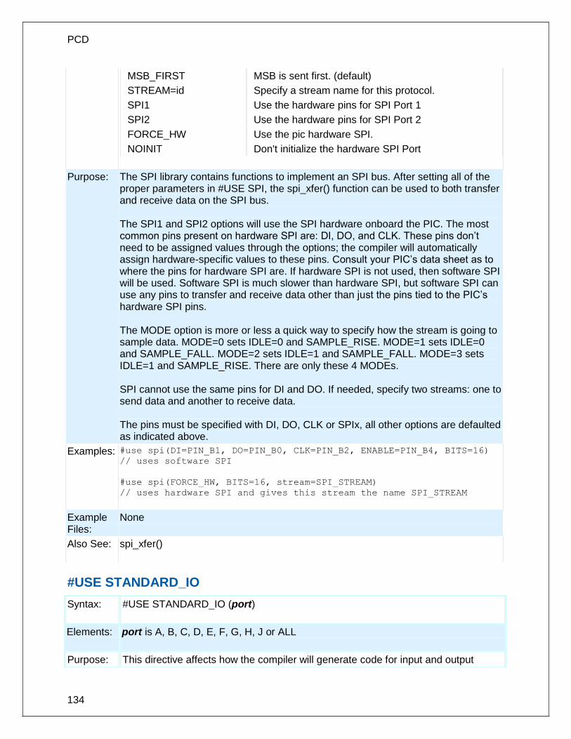
PCD
134
MSB_FIRST MSB is sent first. (default)
STREAM=id Specify a stream name for this protocol.
SPI1 Use the hardware pins for SPI Port 1
SPI2 Use the hardware pins for SPI Port 2
FORCE_HW Use the pic hardware SPI.
NOINIT Don't initialize the hardware SPI Port
Purpose: The SPI library contains functions to implement an SPI bus. After setting all of the proper parameters in #USE SPI, the spi_xfer() function can be used to both transfer and receive data on the SPI bus. The SPI1 and SPI2 options will use the SPI hardware onboard the PIC. The most common pins present on hardware SPI are: DI, DO, and CLK. These pins don’t need to be assigned values through the options; the compiler will automatically assign hardware-specific values to these pins. Consult your PIC’s data sheet as to where the pins for hardware SPI are. If hardware SPI is not used, then software SPI will be used. Software SPI is much slower than hardware SPI, but software SPI can use any pins to transfer and receive data other than just the pins tied to the PIC’s hardware SPI pins. The MODE option is more or less a quick way to specify how the stream is going to sample data. MODE=0 sets IDLE=0 and SAMPLE_RISE. MODE=1 sets IDLE=0 and SAMPLE_FALL. MODE=2 sets IDLE=1 and SAMPLE_FALL. MODE=3 sets IDLE=1 and SAMPLE_RISE. There are only these 4 MODEs. SPI cannot use the same pins for DI and DO. If needed, specify two streams: one to send data and another to receive data. The pins must be specified with DI, DO, CLK or SPIx, all other options are defaulted as indicated above.
Examples: #use spi(DI=PIN_B1, DO=PIN_B0, CLK=PIN_B2, ENABLE=PIN_B4, BITS=16) // uses software SPI
#use spi(FORCE_HW, BITS=16, stream=SPI_STREAM)
// uses hardware SPI and gives this stream the name SPI_STREAM
Example Files:
None
Also See: spi_xfer()
#USE STANDARD_IO
Syntax: #USE STANDARD_IO (port)
Elements: port is A, B, C, D, E, F, G, H, J or ALL
Purpose: This directive affects how the compiler will generate code for input and output

Pre-Processor
135
instructions that follow. This directive takes effect until another #USE XXX_IO directive is encountered. The standard method of doing I/O will cause the compiler to generate code to make an I/O pin either input or output every time it is used. On the 5X processors this requires one byte of RAM for every port set to standard I/O. Standard_io is the default I/O method for all ports. When linking multiple compilation units be aware this directive only applies to the current compilation unit.
Examples: #use standard_io(A)
Example Files:
ex_cust.c
Also See: #USE FAST_IO, #USE FIXED_IO, General Purpose I/O
#USE TIMER
Syntax: #USE TIMER (options)
Elements: TIMER=x Sets the timer to use as the tick timer. x is a valid timer that the PIC has. Default value is 1 for Timer 1. TICK=xx Sets the desired time for 1 tick. xx can be used with ns(nanoseconds), us (microseconds), ms (milliseconds), or s (seconds). If the desired tick time can't be achieved it will set the time to closest achievable time and will generate a warning specifying the exact tick time. The default value is 1us. BITS=x Sets the variable size used by the get_ticks() and set_ticks() functions for returning and setting the tick time. x can be 8 for 8 bits, 16 for 16 bits or 32 for 32bits. The default is 32 for 32 bits. ISR Uses the timer's interrupt to increment the upper bits of the tick timer. This mode requires the the global interrupt be enabled in the main program. NOISR The get_ticks() function increments the upper bits of the tick timer. This requires that the get_ticks() function be called more often then the timer's overflow rate. NOISR is the default mode of operation. STREAM=id Associates a stream identifier with the tick timer. The identifier may be used in functions like get_ticks().
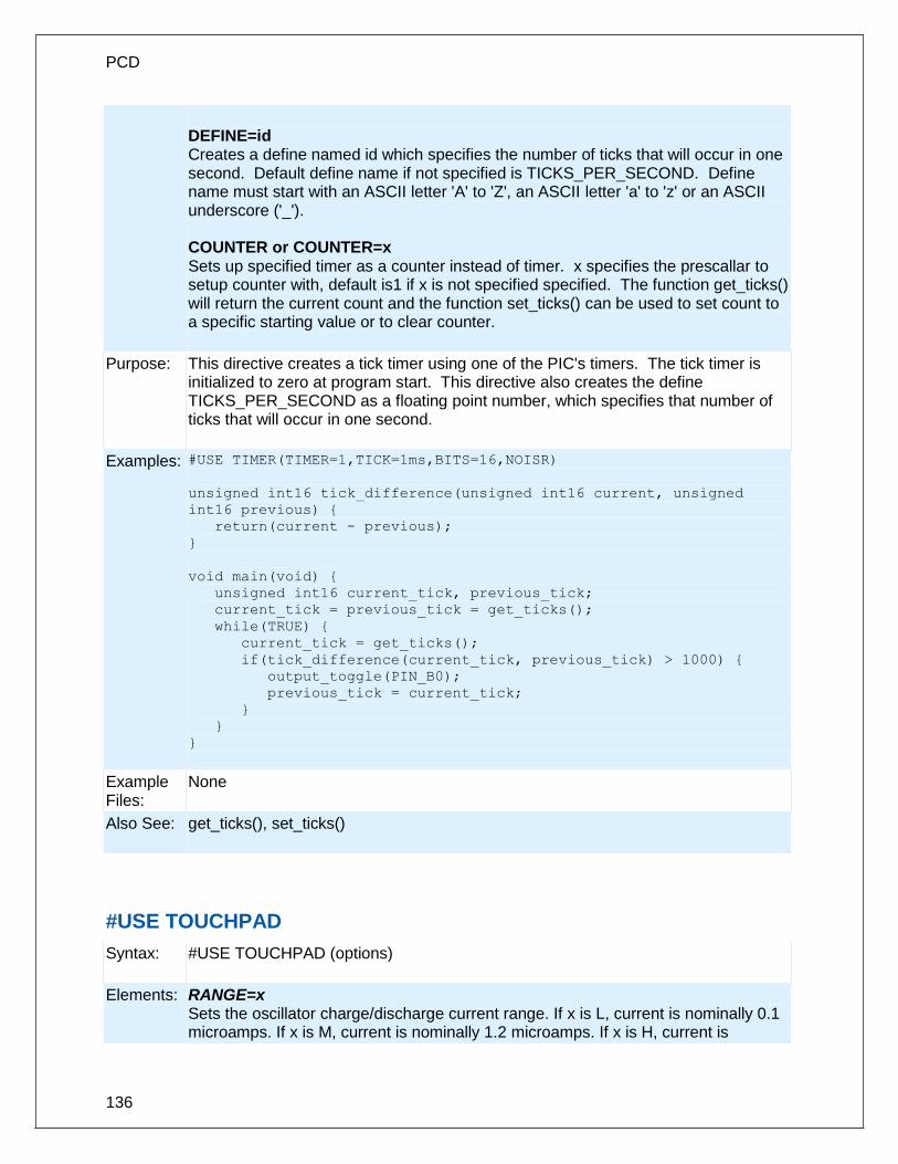
PCD
136
DEFINE=id Creates a define named id which specifies the number of ticks that will occur in one second. Default define name if not specified is TICKS_PER_SECOND. Define name must start with an ASCII letter 'A' to 'Z', an ASCII letter 'a' to 'z' or an ASCII underscore ('_'). COUNTER or COUNTER=x Sets up specified timer as a counter instead of timer. x specifies the prescallar to setup counter with, default is1 if x is not specified specified. The function get_ticks() will return the current count and the function set_ticks() can be used to set count to a specific starting value or to clear counter.
Purpose: This directive creates a tick timer using one of the PIC's timers. The tick timer is initialized to zero at program start. This directive also creates the define TICKS_PER_SECOND as a floating point number, which specifies that number of ticks that will occur in one second.
Examples: #USE TIMER(TIMER=1,TICK=1ms,BITS=16,NOISR)
unsigned int16 tick_difference(unsigned int16 current, unsigned
int16 previous) {
return(current - previous);
}
void main(void) {
unsigned int16 current_tick, previous_tick;
current_tick = previous_tick = get_ticks();
while(TRUE) {
current_tick = get_ticks();
if(tick_difference(current_tick, previous_tick) > 1000) {
output_toggle(PIN_B0);
previous_tick = current_tick;
}
}
}
Example Files:
None
Also See: get_ticks(), set_ticks()
#USE TOUCHPAD
Syntax: #USE TOUCHPAD (options)
Elements: RANGE=x Sets the oscillator charge/discharge current range. If x is L, current is nominally 0.1 microamps. If x is M, current is nominally 1.2 microamps. If x is H, current is

Pre-Processor
137
nominally 18 microamps. Default value is H (18 microamps). THRESHOLD=x x is a number between 1-100 and represents the percent reduction in the nominal frequency that will generate a valid key press in software. Default value is 6%. SCANTIME=xxMS xx is the number of milliseconds used by the microprocessor to scan for one key press. If utilizing multiple touch pads, each pad will use xx milliseconds to scan for one key press. Default is 32ms. PIN=char If a valid key press is determined on “PIN”, the software will return the character “char” in the function touchpad_getc(). (Example: PIN_B0='A') SOURCETIME=xxus (CTMU only) xx is thenumber of microseconds each pin is sampled for by ADC during each scan time period. Default is 10us.
Purpose: This directive will tell the compiler to initialize and activate the Capacitive Sensing Module (CSM)or Charge Time Measurement Unit (CTMU) on the microcontroller. The compiler requires use of the TIMER0 and TIMER1 modules for CSM and Timer1 ADC modules for CTMU, and global interrupts must still be activated in the main program in order for the CSM or CTMU to begin normal operation. For most applications, a higher RANGE, lower THRESHOLD, and higher SCANTIME will result better key press detection. Multiple PIN's may be declared in “options”, but they must be valid pins used by the CSM or CTMU. The user may also generate a TIMER0 ISR with TIMER0's interrupt occuring every SCANTIME milliseconds. In this case, the CSM's or CTMU's ISR will be executed first.
Examples: #USE TOUCHPAD (THRESHOLD=5, PIN_D5='5', PIN_B0='C') void main(void){
char c;
enable_interrupts(GLOBAL);
while(1){
c = TOUCHPAD_GETC(); //will wait until a pin is detected
} //if PIN_B0 is pressed, c will have 'C'
} //if PIN_D5 is pressed, c will have '5'
Example Files:
None
Also See: touchpad_state( ), touchpad_getc( ), touchpad_hit( )
#WARNING
Syntax: #WARNING text
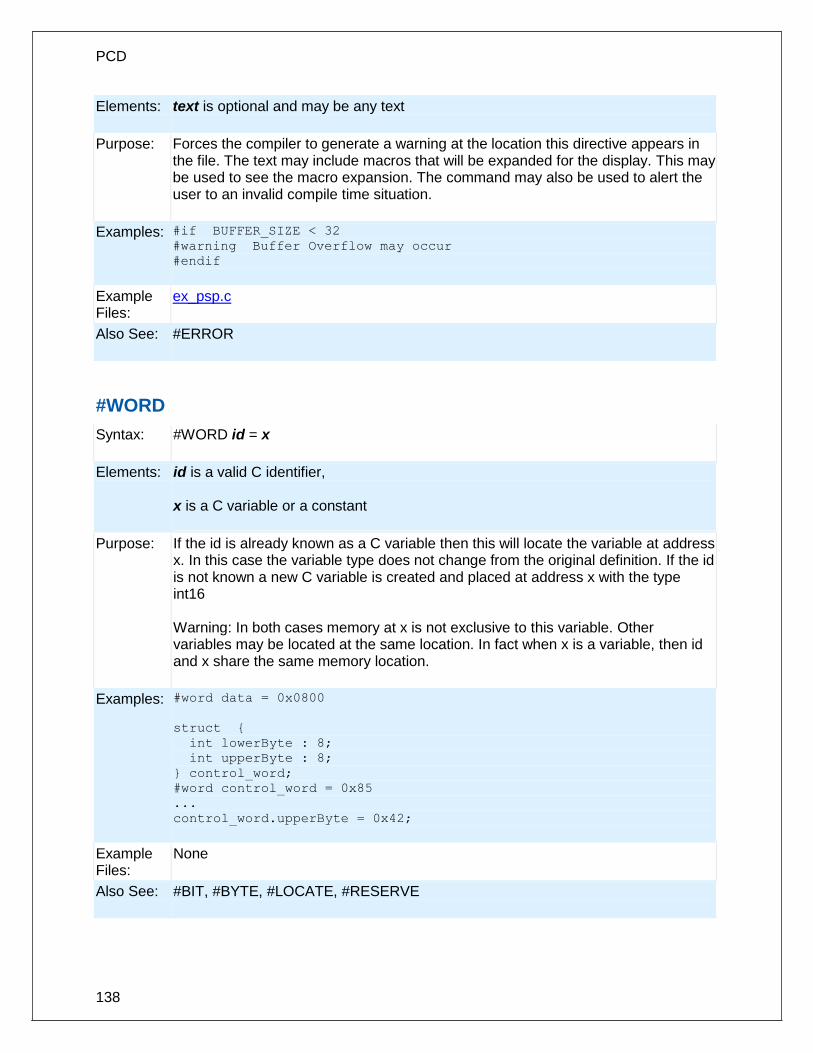
PCD
138
Elements: text is optional and may be any text
Purpose: Forces the compiler to generate a warning at the location this directive appears in the file. The text may include macros that will be expanded for the display. This may be used to see the macro expansion. The command may also be used to alert the user to an invalid compile time situation.
Examples: #if BUFFER_SIZE < 32 #warning Buffer Overflow may occur
#endif
Example Files:
ex_psp.c
Also See: #ERROR
#WORD
Syntax: #WORD id = x
Elements: id is a valid C identifier, x is a C variable or a constant
Purpose: If the id is already known as a C variable then this will locate the variable at address x. In this case the variable type does not change from the original definition. If the id is not known a new C variable is created and placed at address x with the type int16 Warning: In both cases memory at x is not exclusive to this variable. Other variables may be located at the same location. In fact when x is a variable, then id and x share the same memory location.
Examples: #word data = 0x0800
struct {
int lowerByte : 8;
int upperByte : 8;
} control_word;
#word control_word = 0x85
...
control_word.upperByte = 0x42;
Example Files:
None
Also See: #BIT, #BYTE, #LOCATE, #RESERVE

Pre-Processor
139
#ZERO_RAM
Syntax: #ZERO_RAM
Elements: None
Purpose: This directive zero's out all of the internal registers that may be used to hold variables before program execution begins.
Examples: #zero_ram
void main() {
}
Example Files:
ex_cust.c
Also See: None

140
BUILT-IN FUNCTIONS
BUILT-IN FUNCTIONS
The CCS compiler provides a lot of built-in functions to access and use the PIC microcontroller's peripherals. This makes it very easy for the users to configure and use the peripherals without going into in depth details of the registers associated with the functionality. The functions categorized by the peripherals associated with them are listed on the next page. Click on the function name to get a complete description and parameter and return value descriptions.
abs( ) ................................................................................................................................... 146 sin( ) cos( ) tan( ) asin( ) acos() atan() sinh() cosh() tanh() atan2() ...................................... 146 adc_done( ) ......................................................................................................................... 147 assert( ) ............................................................................................................................... 148 atoe ..................................................................................................................................... 149 atof( ) ................................................................................................................................... 149 pin_select() .......................................................................................................................... 150 atoi( ) atol( ) atoi32( ) ........................................................................................................... 151 bit_clear( ) ........................................................................................................................... 152 bit_set( ) .............................................................................................................................. 152 bit_test( ) ............................................................................................................................. 153 brownout_enable( ).............................................................................................................. 154 bsearch( ) ............................................................................................................................ 154 calloc( ) ................................................................................................................................ 155 ceil( ) ................................................................................................................................... 156 clc1_setup_gate() clc2_setup_gate() clc3_setup_gate() clc4_setup_gate() ......................... 156 clc1_setup_input() clc2_setup_input() clc3_setup_input() clc4_setup_input() ...................... 157 clear_interrupt( ) .................................................................................................................. 158 cwg_status( ) ....................................................................................................................... 158 cwg_restart( ) ...................................................................................................................... 159 dac_write( ) ......................................................................................................................... 159 delay_cycles( ) .................................................................................................................... 160 delay_ms( ) ......................................................................................................................... 160 delay_us( ) .......................................................................................................................... 161 disable_interrupts( ) ............................................................................................................. 162 div( ) ldiv( ) .......................................................................................................................... 163 enable_interrupts( ) ............................................................................................................. 164 erase_eeprom( ) .................................................................................................................. 164 erase_program_eeprom( ) ................................................................................................... 165 exp( ) ................................................................................................................................... 165 ext_int_edge( ) .................................................................................................................... 166 fabs( ) .................................................................................................................................. 167 getc( ) getch( ) getchar( ) fgetc( ) ......................................................................................... 167 gets( ) fgets( ) ...................................................................................................................... 168 floor( ) .................................................................................................................................. 169 fmod( ) ................................................................................................................................. 170 printf( ) fprintf( ) .................................................................................................................... 170

Built-in Functions
141
putc( ) putchar( ) fputc( ) ...................................................................................................... 172 puts( ) fputs( ) ...................................................................................................................... 173 free( )................................................................................................................................... 173 frexp( ) ................................................................................................................................. 174 get_capture_event() ............................................................................................................ 175 get_capture_time() .............................................................................................................. 175 get_nco_accumulator( ) ....................................................................................................... 175 get_nco_inc_value( ) ........................................................................................................... 176 get_ticks( ) ........................................................................................................................... 176 get_timerA( )........................................................................................................................ 177 get_timerB( )........................................................................................................................ 177 get_timerx( ) ........................................................................................................................ 178 get_tris_x( ) ......................................................................................................................... 179 getenv( ) .............................................................................................................................. 179 gets( ) fgets( ) ...................................................................................................................... 183 goto_address( ) ................................................................................................................... 184 high_speed_adc_done( ) ..................................................................................................... 184 i2c_init( ) .............................................................................................................................. 185 i2c_isr_state( ) ..................................................................................................................... 186 i2c_poll( ) ............................................................................................................................. 186 i2c_read( ) ........................................................................................................................... 187 i2c_slaveaddr( ) ................................................................................................................... 188 i2c_speed( )......................................................................................................................... 188 i2c_start( ) ........................................................................................................................... 189 i2c_stop( ) ........................................................................................................................... 190 i2c_write( ) ........................................................................................................................... 190 input( ) ................................................................................................................................. 191 input_change_x( ) ................................................................................................................ 192 input_state( ) ....................................................................................................................... 193 input_x( ) ............................................................................................................................. 194 interrupt_active( ) ................................................................................................................ 194 isalnum(char) isalpha(char) isdigit(char) islower(char) isspace(char) isupper(char) isxdigit(char) iscntrl(x) isgraph(x) isprint(x) ispunct(x) .......................................................... 195 isamong( ) ........................................................................................................................... 196 itoa( ) ................................................................................................................................... 197 jump_to_isr( ) ...................................................................................................................... 197 kbhit( ) ................................................................................................................................. 198 label_address( ) ................................................................................................................... 199 labs( ) .................................................................................................................................. 199 lcd_contrast( ) ...................................................................................................................... 200 lcd_load( ) ........................................................................................................................... 200 lcd_symbol( ) ....................................................................................................................... 201 ldexp( ) ................................................................................................................................ 202 log( ) .................................................................................................................................... 202 log10( ) ................................................................................................................................ 203 longjmp( ) ............................................................................................................................ 203 make8( ) .............................................................................................................................. 204 make16( ) ............................................................................................................................ 205 make32( ) ............................................................................................................................ 205 malloc( ) .............................................................................................................................. 206 memcpy( ) memmove( ) ...................................................................................................... 206

PCD
142
memset( ) ............................................................................................................................ 207 modf( ) ................................................................................................................................. 208 _mul( ) ................................................................................................................................. 208 nargs( ) ................................................................................................................................ 209 offsetof( ) offsetofbit( ) ......................................................................................................... 210 output_x( ) ........................................................................................................................... 211 output_bit( ) ......................................................................................................................... 211 output_drive( ) ..................................................................................................................... 212 output_float( ) ...................................................................................................................... 213 output_high( ) ...................................................................................................................... 214 output_low( )........................................................................................................................ 214 output_toggle( ) ................................................................................................................... 215 perror( ) ............................................................................................................................... 215 port_x_pullups ( ) ................................................................................................................. 216 pow( ) pwr( ) ........................................................................................................................ 217 printf( ) fprintf( ) .................................................................................................................... 217 profileout() ........................................................................................................................... 219 psp_output_full( ) psp_input_full( ) psp_overflow( ) ............................................................. 220 putc( ) putchar( ) fputc( ) ...................................................................................................... 221 putc_send( ); ....................................................................................................................... 221 fputc_send( ); ...................................................................................................................... 221 pwm_off() ............................................................................................................................ 222 pwm_on() ............................................................................................................................ 223 pwm_set_duty() ................................................................................................................... 223 pwm_set_duty_percent ....................................................................................................... 224 pwm_set_frequency ............................................................................................................ 224 qei_get_count( ) .................................................................................................................. 225 qei_set_count( ) ................................................................................................................... 225 qei_status( )......................................................................................................................... 226 qsort( ) ................................................................................................................................. 226 rand( ).................................................................................................................................. 227 rcv_buffer_bytes( )............................................................................................................... 228 rcv_buffer_full( ) .................................................................................................................. 228 read_adc( ) .......................................................................................................................... 229 read_bank( ) ........................................................................................................................ 230 read_calibration( ) ............................................................................................................... 231 read_configuration_memory( ) ............................................................................................. 231 read_eeprom( ) .................................................................................................................... 232 read_extended_ram( ) ......................................................................................................... 232 read_program_memory( ) .................................................................................................... 233 read_external_memory( ) .................................................................................................... 233 read_high_speed_adc( ) ...................................................................................................... 233 read_program_eeprom( ) .................................................................................................... 235 realloc( ) .............................................................................................................................. 235 release_io() ......................................................................................................................... 236 reset_cpu( ) ......................................................................................................................... 237 restart_cause( ) ................................................................................................................... 237 restart_wdt( ) ....................................................................................................................... 238 rotate_left( ) ......................................................................................................................... 239 rotate_right( ) ....................................................................................................................... 239 rtc_alarm_read( ) ................................................................................................................. 240

Built-in Functions
143
rtc_alarm_write( ) ................................................................................................................ 240 rtc_read( ) ............................................................................................................................ 241 rtc_write( ) ........................................................................................................................... 242 rtos_await( )......................................................................................................................... 242 rtos_disable( ) ...................................................................................................................... 243 rtos_enable( ) ...................................................................................................................... 243 rtos_msg_poll( ) ................................................................................................................... 244 rtos_msg_read( ) ................................................................................................................. 244 rtos_msg_send( ) ................................................................................................................ 245 rtos_overrun( ) ..................................................................................................................... 245 rtos_run( ) ............................................................................................................................ 246 rtos_signal( )........................................................................................................................ 246 rtos_stats( ) ......................................................................................................................... 247 rtos_terminate( ) .................................................................................................................. 247 rtos_wait( ) .......................................................................................................................... 248 rtos_yield( ) ......................................................................................................................... 248 set_adc_channel( ) .............................................................................................................. 249 set_nco_inc_value( ) ........................................................................................................... 250 set_power_pwm_override( ) ................................................................................................ 251 set_power_pwmx_duty( ) .................................................................................................... 251 set_pwm1_duty( ) set_pwm2_duty( ) set_pwm3_duty( ) set_pwm4_duty( ) set_pwm5_duty( ) ................................................................................................................ 252 set_ticks( ) ........................................................................................................................... 253 set_timerA( ) ........................................................................................................................ 253 set_timerB( ) ........................................................................................................................ 254 set_timerx( ) ........................................................................................................................ 254 set_tris_x( ) ......................................................................................................................... 255 set_uart_speed( ) ................................................................................................................ 256 setjmp( ) .............................................................................................................................. 257 setup_adc(mode) ................................................................................................................ 257 setup_adc_ports( )............................................................................................................... 258 setup_ccp1( ) setup_ccp2( ) setup_ccp3( ) setup_ccp4( ) setup_ccp5( ) setup_ccp6( ) ....................................................................................................................... 259 setup_clc1() setup_clc2() setup_clc3() setup_clc4() ............................................................ 261 setup_comparator( ) ............................................................................................................ 261 setup_counters( ) ................................................................................................................ 262 setup_cwg( ) ........................................................................................................................ 263 setup_dac( ) ........................................................................................................................ 264 setup_external_memory( ) ................................................................................................... 265 setup_high_speed_adc( ) .................................................................................................... 265 setup_high_speed_adc_pair( ) ............................................................................................ 266 setup_lcd( ) ......................................................................................................................... 267 setup_low_volt_detect( ) ...................................................................................................... 268 setup_nco( ) ........................................................................................................................ 268 setup_opamp1( ) setup_opamp2( ) ...................................................................................... 269 setup_oscillator( ) ................................................................................................................ 269 setup_pmp(option,address_mask) ....................................................................................... 270 setup_power_pwm( ) ........................................................................................................... 271 setup_power_pwm_pins( ) ................................................................................................... 272 setup_psp(option,address_mask) ........................................................................................ 273 setup_pwm1( ) setup_pwm2( ) setup_pwm3( ) setup_pwm4( ) ............................................ 274

PCD
144
setup_qei( ) ......................................................................................................................... 275 setup_rtc( ) .......................................................................................................................... 275 setup_rtc_alarm( ) ............................................................................................................... 276 setup_spi( ) setup_spi2( ) .................................................................................................... 276 setup_timer_A( ) .................................................................................................................. 277 setup_timer_B( ) .................................................................................................................. 277 setup_timer_0( ) .................................................................................................................. 278 setup_timer_1( ) .................................................................................................................. 279 setup_timer_2( ) .................................................................................................................. 279 setup_timer_3( ) .................................................................................................................. 280 setup_timer_4( ) .................................................................................................................. 281 setup_timer_5( ) .................................................................................................................. 281 setup_uart( ) ........................................................................................................................ 282 setup_vref( ) ........................................................................................................................ 283 setup_wdt( )......................................................................................................................... 283 shift_left( ) ........................................................................................................................... 284 shift_right( ) ......................................................................................................................... 284 sleep( ) ................................................................................................................................ 285 sleep_ulpwu( ) ..................................................................................................................... 286 spi_data_is_in( ) spi_data_is_in2( ) ..................................................................................... 286 spi_init() ............................................................................................................................... 287 spi_prewrite(data); ............................................................................................................... 288 spi_read( ) spi_read2( ) ..................................................................................................... 288 spi_read_16() ...................................................................................................................... 289 spi_read2_16() .................................................................................................................... 289 spi_read3_16() .................................................................................................................... 289 spi_read4_16() .................................................................................................................... 289 spi_speed ............................................................................................................................ 290 spi_write( ) spi_write2( ) ...................................................................................................... 290 spi_xfer( ) ............................................................................................................................ 291 SPII_XFER_IN() .................................................................................................................. 292 sprintf( ) ............................................................................................................................... 292 sqrt( ) ................................................................................................................................... 293 srand( ) ................................................................................................................................ 293 STANDARD STRING FUNCTIONS( ) memchr( ) memcmp( ) strcat( ) strchr( ) strcmp( ) strcoll( ) strcspn( ) strerror( ) stricmp( ) strlen( ) strlwr( ) strncat( ) strncmp( ) strncpy( ) strpbrk( ) strrchr( ) strspn( ) strstr( ) strxfrm( ) ...................................... 294 strtod( ) ................................................................................................................................ 295 strtok( ) ................................................................................................................................ 296 strtol( ) ................................................................................................................................. 297 strtoul( ) ............................................................................................................................... 298 swap( ) ................................................................................................................................ 299 tolower( ) toupper( ) ............................................................................................................. 299 touchpad_getc( ) ................................................................................................................. 300 touchpad_hit( ) .................................................................................................................... 301 touchpad_state( ) ................................................................................................................ 301 tx_buffer_bytes() ................................................................................................................. 302 tx_buffer_full( ) .................................................................................................................... 303 va_arg( ) .............................................................................................................................. 303 va_end( ) ............................................................................................................................. 304 va_start ............................................................................................................................... 305

Built-in Functions
145
write_bank( )........................................................................................................................ 305 write_configuration_memory( ) ............................................................................................ 306 write_eeprom( ) ................................................................................................................... 306 write_external_memory( ) .................................................................................................... 307 write_extended_ram( ) ......................................................................................................... 308 write_program_eeprom( ) .................................................................................................... 308 write_program_memory( ) ................................................................................................... 309

PCD
146
abs( )
Syntax: value = abs(x)
Parameters: x is a signed 8, 16, or 32 bit int or a float
Returns: Same type as the parameter.
Function: Computes the absolute value of a number.
Availability: All devices
Requires: #INCLUDE <stdlib.h>
Examples: signed int target,actual;
...
error = abs(target-actual);
Example Files: None
Also See: labs()
sin( ) cos( ) tan( ) asin( ) acos() atan() sinh() cosh() tanh() atan2()
Syntax: val = sin (rad) val = cos (rad) val = tan (rad) rad = asin (val) rad1 = acos (val) rad = atan (val) rad2=atan2(val, val) result=sinh(value) result=cosh(value) result=tanh(value)
Parameters: rad is a float representing an angle in Radians -2pi to 2pi. val is a float with the range -1.0 to 1.0. Value is a float
Returns: rad is a float representing an angle in Radians -pi/2 to pi/2 val is a float with the range -1.0 to 1.0. rad1 is a float representing an angle in Radians 0 to pi rad2 is a float representing an angle in Radians -pi to pi

Built-in Functions
147
Result is a float
Function: These functions perform basic Trigonometric functions. sin returns the sine value of the parameter (measured in radians) cos returns the cosine value of the parameter (measured in radians) tan returns the tangent value of the parameter (measured in radians) asin returns the arc sine value in the range [-pi/2,+pi/2] radians acos returns the arc cosine value in the range[0,pi] radians atan returns the arc tangent value in the range [-pi/2,+pi/2] radians atan2 returns the arc tangent of y/x in the range [-pi,+pi] radians sinh returns the hyperbolic sine of x cosh returns the hyperbolic cosine of x tanh returns the hyperbolic tangent of x Note on error handling: If "errno.h" is included then the domain and range errors are stored in the errno variable. The user can check the errno to see if an error has occurred and print the error using the perror function. Domain error occurs in the following cases: asin: when the argument not in the range[-1,+1] acos: when the argument not in the range[-1,+1] atan2: when both arguments are zero Range error occur in the following cases: cosh: when the argument is too large sinh: when the argument is too large
Availability: All devices
Requires: #INCLUDE <math.h>
Examples: float phase;
// Output one sine wave
for(phase=0; phase<2*3.141596; phase+=0.01)
set_analog_voltage( sin(phase)+1 );
Example Files:
ex_tank.c
Also See: log(), log10(), exp(), pow(), sqrt()
adc_done( )
Syntax: value = adc_done();
Parameters: None

PCD
148
Returns: A short int. TRUE if the A/D converter is done with conversion, FALSE if it is still busy.
Function: Can be polled to determine if the A/D has valid data.
Availability: Only available on devices with built in analog to digital converters
Requires: None
Examples: int16 value;
setup_adc_ports(sAN0|sAN1, VSS_VDD);
setup_adc(ADC_CLOCK_DIV_4|ADC_TAD_MUL_8);
set_adc_channel(0);
read_adc(ADC_START_ONLY);
int1 done = adc_done();
while(!done) {
done = adc_done();
}
value = read_adc(ADC_READ_ONLY);
printf(“A/C value = %LX\n\r”, value);
}
Example Files:
None
Also See: setup_adc(), set_adc_channel(), setup_adc_ports(), read_adc(), ADC Overview
assert( )
Syntax: assert (condition);
Parameters: condition is any relational expression
Returns: Nothing
Function: This function tests the condition and if FALSE will generate an error message on STDERR (by default the first USE RS232 in the program). The error message will include the file and line of the assert(). No code is generated for the assert() if you #define NODEBUG. In this way you may include asserts in your code for testing and quickly eliminate them from the final program.
Availability: All devices
Requires: assert.h and #USE RS232

Built-in Functions
149
Examples: assert( number_of_entries<TABLE_SIZE );
// If number_of_entries is >= TABLE_SIZE then
// the following is output at the RS232:
// Assertion failed, file myfile.c, line 56
Example Files:
None
Also See: #USE RS232, RS232 I/O Overview
atoe
Syntax: atoe(string);
Parameters: string is a pointer to a null terminated string of characters.
Returns: Result is a floating point number
Function: Converts the string passed to the function into a floating point representation. If the result cannot be represented, the behavior is undefined. This function also handles E format numbers
Availability: All devices
Requires: #INCLUDE <stdlib.h>
Examples: char string [10];
float32 x;
strcpy (string, "12E3");
x = atoe(string);
// x is now 12000.00
Example Files:
None
Also See:
atoi(), atol(), atoi32(), atof(), printf()
atof( )
Syntax: result = atof (string)
Parameters: string is a pointer to a null terminated string of characters.

PCD
150
Returns: Result is a floating point number
Function: Converts the string passed to the function into a floating point representation. If the result cannot be represented, the behavior is undefined.
Availability: All devices
Requires: #INCLUDE <stdlib.h>
Examples: char string [10];
float x;
strcpy (string, "123.456");
x = atof(string);
// x is now 123.456
Example Files:
ex_tank.c
Also See: atoi(), atol(), atoi32(), printf()
pin_select()
Syntax: pin_select(peripheral_pin, pin, [unlock],[lock])
Parameters: peripheral_pin – a constant string specifying which peripheral pin to map the specified pin to. Refer to #pin_select for all available strings. Using “NULL” for the peripheral_pin parameter will unassign the output peripheral pin that is currently assigned to the pin passed for the pin parameter. pin – the pin to map to the specified peripheral pin. Refer to device's header file for pin defines. If the peripheral_pin parameter is an input, passing FALSE for the pin parameter will unassign the pin that is currently assigned to that peripheral pin. unlock – optional parameter specifying whether to perform an unlock sequence before writing the RPINRx or RPORx register register determined by peripheral_pin and pin options. Default is TRUE if not specified. The unlock sequence must be performed to allow writes to the RPINRx and RPORx registers. This option allows calling pin_select() multiple times without performing an unlock sequence each time. lock – optional parameter specifying whether to perform a lock sequence after writing the RPINRx or RPORx registers. Default is TRUE if not specified. Although not necessary it is a good idea to lock the RPINRx and RPORx registers from writes after all pins have been mapped. This option allows calling pin_select() multiple times without performing a lock sequence each time.
Returns: Nothing.

Built-in Functions
151
Availability: On device with remappable peripheral pins.
Requires: Pin defines in device's header file.
Examples: pin_select(“U2TX”,PIN_B0); //Maps PIN_B0 to U2TX //peripheral pin, performs unlock //and lock sequences. pin_select(“U2TX”,PIN_B0,TRUE,FALSE); //Maps PIN_B0 to U2TX //peripheral pin and performs //unlock sequence. pin_select(“U2RX”,PIN_B1,FALSE,TRUE); //Maps PIN_B1 to U2RX //peripheral pin and performs lock //sequence.
Example Files:
None.
Also See: #pin_select
atoi( ) atol( ) atoi32( )
Syntax: ivalue = atoi(string) or lvalue = atol(string) or i32value = atoi32(string)
Parameters: string is a pointer to a null terminated string of characters.
Returns: ivalue is an 8 bit int. lvalue is a 16 bit int. i32value is a 32 bit int.
Function: Converts the string passed to the function into an int representation. Accepts both decimal and hexadecimal argument. If the result cannot be represented, the behavior is undefined.
Availability: All devices
Requires: #INCLUDE <stdlib.h>
Examples: char string[10];
int x;

PCD
152
strcpy(string,"123");
x = atoi(string);
// x is now 123
Example Files:
input.c
Also See: printf()
bit_clear( )
Syntax: bit_clear(var, bit)
Parameters: var may be a any bit variable (any lvalue) bit is a number 0- 31 representing a bit number, 0 is the least significant bit.
Returns: undefined
Function: Simply clears the specified bit (0-7, 0-15 or 0-31) in the given variable. The least significant bit is 0. This function is the similar to: var &= ~(1<<bit);
Availability: All devices
Requires: Nothing
Examples: int x;
x=5;
bit_clear(x,2);
// x is now 1
Example Files:
ex_patg.c
Also See: bit_set(), bit_test()
bit_set( )
Syntax:
bit_set(var, bit)
Parameters:
var may be a 8,16 or 32 bit variable (any lvalue) bit is a number 0- 31 representing a bit number, 0 is the least significant bit.
Returns: Undefined
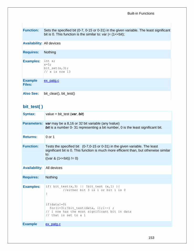
Built-in Functions
153
Function:
Sets the specified bit (0-7, 0-15 or 0-31) in the given variable. The least significant bit is 0. This function is the similar to: var |= (1<<bit);
Availability:
All devices
Requires:
Nothing
Examples:
int x;
x=5;
bit_set(x,3);
// x is now 13
Example Files:
ex_patg.c
Also See:
bit_clear(), bit_test()
bit_test( )
Syntax:
value = bit_test (var, bit)
Parameters:
var may be a 8,16 or 32 bit variable (any lvalue) bit is a number 0- 31 representing a bit number, 0 is the least significant bit.
Returns:
0 or 1
Function:
Tests the specified bit (0-7,0-15 or 0-31) in the given variable. The least significant bit is 0. This function is much more efficient than, but otherwise similar to: ((var & (1<<bit)) != 0)
Availability:
All devices
Requires:
Nothing
Examples:
if( bit_test(x,3) || !bit_test (x,1) ){
//either bit 3 is 1 or bit 1 is 0
}
if(data!=0)
for(i=31;!bit_test(data, i);i--) ;
// i now has the most significant bit in data
// that is set to a 1
Example ex_patg.c

PCD
154
Files:
Also See:
bit_clear(), bit_set()
brownout_enable( )
Syntax:
brownout_enable (value)
Parameters:
value – TRUE or FALSE
Returns:
undefined
Function:
Enable or disable the software controlled brownout. Brownout will cause the PIC to reset if the power voltage goes below a specific set-point.
Availability:
This function is only available on PICs with a software controlled brownout. This may also require a specific configuration bit/fuse to be set for the brownout to be software controlled.
Requires:
Nothing
Examples:
brownout_enable(TRUE);
Example Files:
None
Also See:
restart_cause()
bsearch( )
Syntax: ip = bsearch (&key, base, num, width, compare)
Parameters: key: Object to search for base: Pointer to array of search data num: Number of elements in search data width: Width of elements in search data compare: Function that compares two elements in search data
Returns: bsearch returns a pointer to an occurrence of key in the array pointed to by base. If key is not found, the function returns NULL. If the array is not in order or contains duplicate records with identical keys, the result is unpredictable.
Function: Performs a binary search of a sorted array
Availability: All devices

Built-in Functions
155
Requires: #INCLUDE <stdlib.h>
Examples: int nums[5]={1,2,3,4,5};
int compar(const void *arg1,const void *arg2);
void main() {
int *ip, key;
key = 3;
ip = bsearch(&key, nums, 5, sizeof(int), compar);
}
int compar(const void *arg1,const void *arg2) {
if ( * (int *) arg1 < ( * (int *) arg2) return –1
else if ( * (int *) arg1 == ( * (int *) arg2) return 0
else return 1;
}
Example Files:
None
Also See: qsort()
calloc( )
Syntax: ptr=calloc(nmem, size)
Parameters: nmem is an integer representing the number of member objects size is the number of bytes to be allocated for each one of them.
Returns: A pointer to the allocated memory, if any. Returns null otherwise.
Function: The calloc function allocates space for an array of nmem objects whose size is specified by size. The space is initialized to all bits zero.
Availability: All devices
Requires: #INCLUDE <stdlibm.h>
Examples: int * iptr;
iptr=calloc(5,10);
// iptr will point to a block of memory of
// 50 bytes all initialized to 0.
Example Files:
None
Also See: realloc(), free(), malloc()

PCD
156
ceil( )
Syntax: result = ceil (value)
Parameters: value is a float
Returns: A float
Function: Computes the smallest integer value greater than the argument. CEIL(12.67) is 13.00.
Availability: All devices
Requires: #INCLUDE<math.h>
Examples: // Calculate cost based on weight rounded
// up to the next pound
cost = ceil( weight ) * DollarsPerPound;
Example Files:
None
Also See: floor()
clc1_setup_gate() clc2_setup_gate() clc3_setup_gate() clc4_setup_gate()
Syntax: clc1_setup_gate(gate, mode); clc2_setup_gate(gate, mode); clc3_setup_gate(gate, mode); clc4_setup_gate(gate, mode);
Parameters: gate – selects which data gate of the Configurable Logic Cell (CLC) module to setup, value can be 1 to 4. mode – the mode to setup the specified data gate of the CLC module into. The options are: CLC_GATE_AND CLC_GATE_NAND CLC_GATE_NOR CLC_GATE_OR CLC_GATE_CLEAR CLC_GATE_SET
Returns: Undefined

Built-in Functions
157
Function: Sets the logic function performed on the inputs for the specified data gate.
Availability: On devices with a CLC module.
Returns: Undefined.
Examples: clc1_setup_gate(1, CLC_GATE_AND);
clc1_setup_gate(2, CLC_GATE_NAND);
clc1_setup_gate(3, CLC_GATE_CLEAR);
clc1_setup_gate(4, CLC_GATE_SET);
Example Files: None
Also See: setup_clcx(), clcx_setup_input()
clc1_setup_input() clc2_setup_input() clc3_setup_input() clc4_setup_input()
Syntax: clc1_setup_input(input, selection); clc2_setup_input(input, selection); clc3_setup_input(input, selection); clc4_setup_input(input, selection);
Parameters: input – selects which input of the Configurable Logic Cell (CLC) module to setup, value can be 1 to 4. selection – the actual input for the specified input that is actually connected to the data gates of the CLC module. The options are: CLC_INPUT_0 CLC_INPUT_1 CLC_INPUT_2 CLC_INPUT_3 CLC_INPUT_4 CLC_INPUT_5 CLC_INPUT_6 CLC_INPUT_7
Returns: Undefined.
Function: Sets the input for the specified input number that is actually connected to all four data gates of the CLC module. Please refer to the table CLCx DATA INPUT SELECTION in the device's datasheet to determine which of the above selections corresponds to actual input pin or peripheral of the device.

PCD
158
Availability: On devices with a CLC module.
Returns: Undefined.
Examples: clc1_setup_input(1, CLC_INPUT_0);
clc1_setup_input(2, CLC_INPUT_1);
clc1_setup_input(3, CLC_INPUT_2);
clc1_setup_input(4, CLC_INPUT_3);
Example Files: None
Also See: setup_clcx(), clcx_setup_gate()
clear_interrupt( )
Syntax: clear_interrupt(level)
Parameters: level - a constant defined in the devices.h file
Returns: undefined
Function: Clears the interrupt flag for the given level. This function is designed for use with a specific interrupt, thus eliminating the GLOBAL level as a possible parameter. Some chips that have interrupt on change for individual pins allow the pin to be specified like INT_RA1.
Availability: All devices
Requires: Nothing
Examples: clear_interrupt(int_timer1);
Example Files:
None
Also See: enable_interrupts() , #INT , Interrupts Overview disable_interrupts(), interrupt_actvie()
cwg_status( )
Syntax: value = cwg_status( );
Parameters: None

Built-in Functions
159
Returns: the status of the CWG module
Function: To determine if a shutdown event occured causing the module to auto-shutdown
Availability: On devices with a CWG module.
Examples: if(cwg_status( ) == CWG_AUTO_SHUTDOWN)
cwg_restart( );
Example Files:
None
Also See: setup_cwg( ), cwg_restart( )
cwg_restart( )
Syntax: cwg_restart( );
Parameters: None
Returns: Nothing
Function: To restart the CWG module after an auto-shutdown event occurs, when not using auto-raster option of module.
Availability: On devices with a CWG module.
Examples: if(cwg_status( ) == CWG_AUTO_SHUTDOWN)
cwg_restart( );
Example Files:
None
Also See: setup_cwg( ), cwg_status( )
dac_write( )
Syntax: dac_write (value)
Parameters: Value: 8-bit integer value to be written to the DAC module
Returns: undefined
Function: This function will write a 8-bit integer to the specified DAC channel.
Availability: Only available on devices with built in digital to analog converters.

PCD
160
Requires: Nothing
Examples: int i = 0;
setup_dac(DAC_VDD | DAC_OUTPUT);
while(1){
i++;
dac_write(i);
}
Also See: setup_dac( ), DAC Overview, see header file for device selected
delay_cycles( )
Syntax: delay_cycles (count)
Parameters: count - a constant 1-255
Returns: undefined
Function: Creates code to perform a delay of the specified number of instruction clocks (1-255). An instruction clock is equal to four oscillator clocks. The delay time may be longer than requested if an interrupt is serviced during the delay. The time spent in the ISR does not count toward the delay time.
Availability: All devices
Requires: Nothing
Examples: delay_cycles( 1 ); // Same as a NOP
delay_cycles(25); // At 20 mhz a 5us delay
Example Files:
ex_cust.c
Also See: delay_us(), delay_ms()
delay_ms( )
Syntax: delay_ms (time)
Parameters: time - a variable 0-65535(int16) or a constant 0-65535 Note: Previous compiler versions ignored the upper byte of an int16, now the
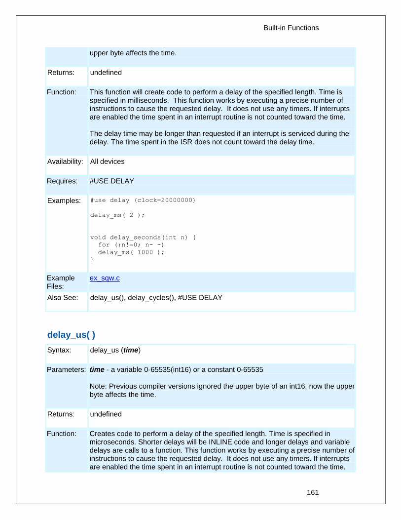
Built-in Functions
161
upper byte affects the time.
Returns: undefined
Function: This function will create code to perform a delay of the specified length. Time is specified in milliseconds. This function works by executing a precise number of instructions to cause the requested delay. It does not use any timers. If interrupts are enabled the time spent in an interrupt routine is not counted toward the time. The delay time may be longer than requested if an interrupt is serviced during the delay. The time spent in the ISR does not count toward the delay time.
Availability: All devices
Requires: #USE DELAY
Examples: #use delay (clock=20000000)
delay_ms( 2 );
void delay_seconds(int n) {
for (;n!=0; n- -)
delay_ms( 1000 );
}
Example Files:
ex_sqw.c
Also See: delay_us(), delay_cycles(), #USE DELAY
delay_us( )
Syntax: delay_us (time)
Parameters: time - a variable 0-65535(int16) or a constant 0-65535 Note: Previous compiler versions ignored the upper byte of an int16, now the upper byte affects the time.
Returns: undefined
Function: Creates code to perform a delay of the specified length. Time is specified in microseconds. Shorter delays will be INLINE code and longer delays and variable delays are calls to a function. This function works by executing a precise number of instructions to cause the requested delay. It does not use any timers. If interrupts are enabled the time spent in an interrupt routine is not counted toward the time.

PCD
162
The delay time may be longer than requested if an interrupt is serviced during the delay. The time spent in the ISR does not count toward the delay time.
Availability: All devices
Requires: #USE DELAY
Examples: #use delay(clock=20000000)
do {
output_high(PIN_B0);
delay_us(duty);
output_low(PIN_B0);
delay_us(period-duty);
} while(TRUE);
Example Files:
ex_sqw.c
Also See: delay_ms(), delay_cycles(), #USE DELAY
disable_interrupts( )
Syntax: disable_interrupts (level)
Parameters: level - a constant defined in the devices .h file
Returns: undefined
Function: Disables the interrupt at the given level. The GLOBAL level will not disable any of the specific interrupts but will prevent any of the specific interrupts, previously enabled to be active. Valid specific levels are the same as are used in #INT_xxx and are listed in the devices .h file. GLOBAL will also disable the peripheral interrupts on devices that have it. Note that it is not necessary to disable interrupts inside an interrupt service routine since interrupts are automatically disabled. Some chips that have interrupt on change for individual pins allow the pin to be specified like INT_RA1.
Availability: Device with interrupts (PCM and PCH)
Requires: Should have a #INT_xxxx, constants are defined in the devices .h file.
Examples: disable_interrupts(GLOBAL); // all interrupts OFF
disable_interrupts(INT_RDA); // RS232 OFF

Built-in Functions
163
enable_interrupts(ADC_DONE);
enable_interrupts(RB_CHANGE);
// these enable the interrupts
// but since the GLOBAL is disabled they
// are not activated until the following
// statement:
enable_interrupts(GLOBAL);
Example Files:
ex_sisr.c, ex_stwt.c
Also See: enable_interrupts(), clear_interrupt (), #INT_xxxx, Interrupts Overview, interrupt_active()
div( ) ldiv( )
Syntax: idiv=div(num, denom) ldiv =ldiv(lnum, ldenom)
Parameters: num and denom are signed integers. num is the numerator and denom is the denominator. lnum and ldenom are signed longs lnum is the numerator and ldenom is the denominator.
Returns: idiv is a structure of type div_t and lidiv is a structure of type ldiv_t. The div function returns a structure of type div_t, comprising of both the quotient and the remainder. The ldiv function returns a structure of type ldiv_t, comprising of both the quotient and the remainder.
Function: The div and ldiv function computes the quotient and remainder of the division of the numerator by the denominator. If the division is inexact, the resulting quotient is the integer or long of lesser magnitude that is the nearest to the algebraic quotient. If the result cannot be represented, the behavior is undefined; otherwise quot*denom(ldenom)+rem shall equal num(lnum).
Availability: All devices.
Requires: #INCLUDE <STDLIB.H>
Examples: div_t idiv;
ldiv_t lidiv;
idiv=div(3,2);
//idiv will contain quot=1 and rem=1
lidiv=ldiv(300,250);
//lidiv will contain lidiv.quot=1 and lidiv.rem=50
Example Files:
None
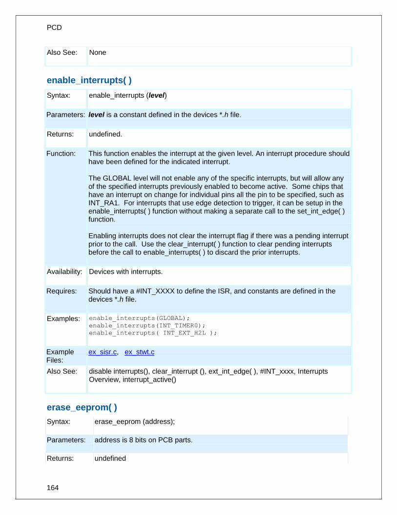
PCD
164
Also See: None
enable_interrupts( )
Syntax: enable_interrupts (level)
Parameters: level is a constant defined in the devices *.h file.
Returns: undefined.
Function: This function enables the interrupt at the given level. An interrupt procedure should have been defined for the indicated interrupt. The GLOBAL level will not enable any of the specific interrupts, but will allow any of the specified interrupts previously enabled to become active. Some chips that have an interrupt on change for individual pins all the pin to be specified, such as INT_RA1. For interrupts that use edge detection to trigger, it can be setup in the enable_interrupts( ) function without making a separate call to the set_int_edge( ) function. Enabling interrupts does not clear the interrupt flag if there was a pending interrupt prior to the call. Use the clear_interrupt( ) function to clear pending interrupts before the call to enable_interrupts( ) to discard the prior interrupts.
Availability: Devices with interrupts.
Requires: Should have a #INT_XXXX to define the ISR, and constants are defined in the devices *.h file.
Examples: enable_interrupts(GLOBAL);
enable_interrupts(INT_TIMER0);
enable_interrupts( INT_EXT_H2L );
Example Files:
ex_sisr.c, ex_stwt.c
Also See: disable interrupts(), clear_interrupt (), ext_int_edge( ), #INT_xxxx, Interrupts Overview, interrupt_active()
erase_eeprom( )
Syntax: erase_eeprom (address);
Parameters: address is 8 bits on PCB parts.
Returns: undefined

Built-in Functions
165
Function: This will erase a row of the EEPROM or Flash Data Memory.
Availability: PCB devices with EEPROM like the 12F519
Requires: Nothing
Examples: erase_eeprom(0); // erase the first row of the EEPROM (8 bytes)
Example Files: None
Also See: write program eeprom(), write program memory(), Program Eeprom Overview
erase_program_eeprom( )
Syntax: erase_program_eeprom (address);
Parameters: address is 16 bits on PCM parts and 32 bits on PCH parts . The least significant bits may be ignored.
Returns: undefined
Function: Erases FLASH_ERASE_SIZE bytes to 0xFFFF in program memory. FLASH_ERASE_SIZE varies depending on the part. For example, if it is 64 bytes then the least significant 6 bits of address is ignored. See write_program_memory() for more information on program memory access.
Availability: Only devices that allow writes to program memory.
Requires: Nothing
Examples: for(i=0x1000;i<=0x1fff;i+=getenv("FLASH_ERASE_SIZE"))
erase_program_memory(i);
Example Files:
None
Also See: write program eeprom(), write program memory(), Program Eeprom Overview
exp( )
Syntax: result = exp (value)

PCD
166
Parameters: value is a float
Returns: A float
Function: Computes the exponential function of the argument. This is e to the power of value where e is the base of natural logarithms. exp(1) is 2.7182818. Note on error handling: If "errno.h" is included then the domain and range errors are stored in the errno variable. The user can check the errno to see if an error has occurred and print the error using the perror function. Range error occur in the following case:
exp: when the argument is too large
Availability: All devices
Requires: #INCLUDE <math.h>
Examples: // Calculate x to the power of y
x_power_y = exp( y * log(x) );
Example Files:
None
Also See: pow(), log(), log10()
ext_int_edge( )
Syntax: ext_int_edge (source, edge)
Parameters: source is a constant 0,1 or 2 for the PIC18XXX and 0 otherwise. Source is optional and defaults to 0. edge is a constant H_TO_L or L_TO_H representing "high to low" and "low to high"
Returns: undefined
Function: Determines when the external interrupt is acted upon. The edge may be L_TO_H or H_TO_L to specify the rising or falling edge.
Availability: Only devices with interrupts (PCM and PCH)
Requires: Constants are in the devices .h file

Built-in Functions
167
Examples: ext_int_edge( 2, L_TO_H); // Set up PIC18 EXT2
ext_int_edge( H_TO_L ); // Sets up EXT
Example Files:
ex_wakup.c
Also See: #INT_EXT , enable_interrupts() , disable_interrupts() , Interrupts Overview
fabs( )
Syntax: result=fabs (value)
Parameters: value is a float
Returns: result is a float
Function: The fabs function computes the absolute value of a float
Availability: All devices.
Requires: #INCLUDE <math.h>
Examples: float result;
result=fabs(-40.0)
// result is 40.0
Example Files: None
Also See: abs(), labs()
getc( ) getch( ) getchar( ) fgetc( )
Syntax: value = getc() value = fgetc(stream) value=getch() value=getchar()
Parameters: stream is a stream identifier (a constant byte)
Returns: An 8 bit character
Function: This function waits for a character to come in over the RS232 RCV pin and returns

PCD
168
the character. If you do not want to hang forever waiting for an incoming character use kbhit() to test for a character available. If a built-in USART is used the hardware can buffer 3 characters otherwise GETC must be active while the character is being received by the PIC®. If fgetc() is used then the specified stream is used where getc() defaults to STDIN (the last USE RS232).
Availability: All devices
Requires: #USE RS232
Examples: printf("Continue (Y,N)?");
do {
answer=getch();
}while(answer!='Y' && answer!='N');
#use rs232(baud=9600,xmit=pin_c6,
rcv=pin_c7,stream=HOSTPC)
#use rs232(baud=1200,xmit=pin_b1,
rcv=pin_b0,stream=GPS)
#use rs232(baud=9600,xmit=pin_b3,
stream=DEBUG)
...
while(TRUE) {
c=fgetc(GPS);
fputc(c,HOSTPC);
if(c==13)
fprintf(DEBUG,"Got a CR\r\n");
}
Example Files:
ex_stwt.c
Also See: putc(), kbhit(), printf(), #USE RS232, input.c, RS232 I/O Overview
gets( ) fgets( )
Syntax: gets (string) value = fgets (string, stream)
Parameters: string is a pointer to an array of characters. Stream is a stream identifier (a constant byte)
Returns: undefined
Function: Reads characters (using getc()) into the string until a RETURN (value 13) is encountered. The string is terminated with a 0. Note that INPUT.C has a more

Built-in Functions
169
versatile get_string function. If fgets() is used then the specified stream is used where gets() defaults to STDIN (the last USE RS232).
Availability: All devices
Requires: #USE RS232
Examples: char string[30];
printf("Password: ");
gets(string);
if(strcmp(string, password))
printf("OK");
Example Files:
None
Also See: getc(), get_string in input.c
floor( )
Syntax: result = floor (value)
Parameters: value is a float
Returns: result is a float
Function: Computes the greatest integer value not greater than the argument. Floor (12.67) is 12.00.
Availability: All devices.
Requires: #INCLUDE <math.h>
Examples: // Find the fractional part of a value
frac = value - floor(value);
Example Files:
None
Also See: ceil()
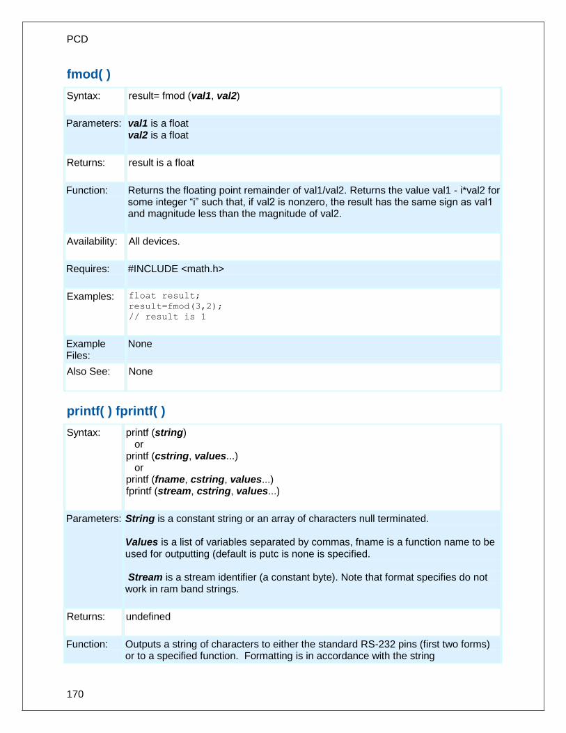
PCD
170
fmod( )
Syntax: result= fmod (val1, val2)
Parameters: val1 is a float val2 is a float
Returns: result is a float
Function: Returns the floating point remainder of val1/val2. Returns the value val1 - i*val2 for some integer “i” such that, if val2 is nonzero, the result has the same sign as val1 and magnitude less than the magnitude of val2.
Availability: All devices.
Requires: #INCLUDE <math.h>
Examples: float result;
result=fmod(3,2);
// result is 1
Example Files:
None
Also See: None
printf( ) fprintf( )
Syntax: printf (string) or printf (cstring, values...) or printf (fname, cstring, values...) fprintf (stream, cstring, values...)
Parameters: String is a constant string or an array of characters null terminated. Values is a list of variables separated by commas, fname is a function name to be used for outputting (default is putc is none is specified. Stream is a stream identifier (a constant byte). Note that format specifies do not work in ram band strings.
Returns: undefined
Function: Outputs a string of characters to either the standard RS-232 pins (first two forms) or to a specified function. Formatting is in accordance with the string
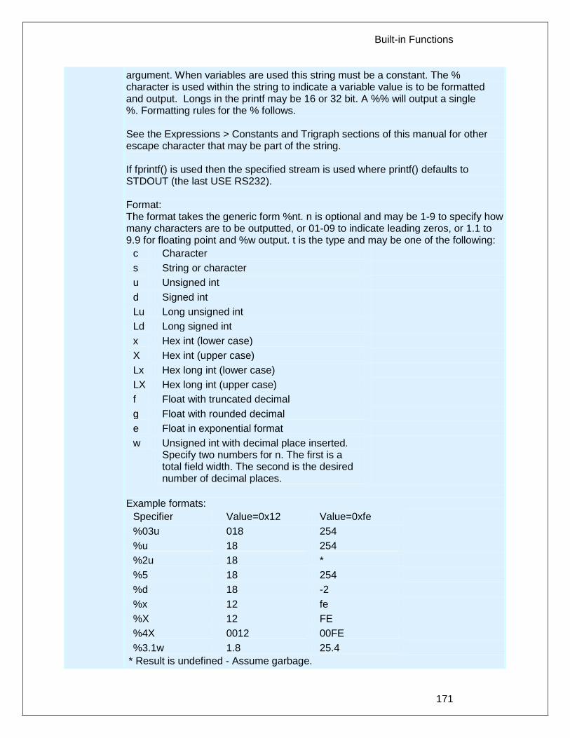
Built-in Functions
171
argument. When variables are used this string must be a constant. The % character is used within the string to indicate a variable value is to be formatted and output. Longs in the printf may be 16 or 32 bit. A %% will output a single %. Formatting rules for the % follows. See the Expressions > Constants and Trigraph sections of this manual for other escape character that may be part of the string. If fprintf() is used then the specified stream is used where printf() defaults to STDOUT (the last USE RS232). Format: The format takes the generic form %nt. n is optional and may be 1-9 to specify how many characters are to be outputted, or 01-09 to indicate leading zeros, or 1.1 to 9.9 for floating point and %w output. t is the type and may be one of the following:
c Character
s String or character
u Unsigned int
d Signed int
Lu Long unsigned int
Ld Long signed int
x Hex int (lower case)
X Hex int (upper case)
Lx Hex long int (lower case)
LX Hex long int (upper case)
f Float with truncated decimal
g Float with rounded decimal
e Float in exponential format
w Unsigned int with decimal place inserted. Specify two numbers for n. The first is a total field width. The second is the desired number of decimal places.
Example formats:
Specifier Value=0x12 Value=0xfe
%03u 018 254
%u 18 254
%2u 18 *
%5 18 254
%d 18 -2
%x 12 fe
%X 12 FE
%4X 0012 00FE
%3.1w 1.8 25.4
* Result is undefined - Assume garbage.

PCD
172
Availability: All Devices
Requires: #USE RS232 (unless fname is used)
Examples: byte x,y,z;
printf("HiThere");
printf("RTCCValue=>%2x\n\r",get_rtcc());
printf("%2u %X %4X\n\r",x,y,z);
printf(LCD_PUTC, "n=%u",n);
Example Files:
ex_admm.c, ex_lcdkb.c
Also See: atoi(), puts(), putc(), getc() (for a stream example), RS232 I/O Overview
putc( ) putchar( ) fputc( )
Syntax: putc (cdata) putchar (cdata) fputc(cdata, stream)
Parameters: cdata is a 8 bit character. Stream is a stream identifier (a constant byte)
Returns: undefined
Function: This function sends a character over the RS232 XMIT pin. A #USE RS232 must appear before this call to determine the baud rate and pin used. The #USE RS232 remains in effect until another is encountered in the file. If fputc() is used then the specified stream is used where putc() defaults to STDOUT (the last USE RS232).
Availability: All devices
Requires: #USE RS232
Examples: putc('*');
for(i=0; i<10; i++)
putc(buffer[i]);
putc(13);
Example Files:
ex_tgetc.c
Also See: getc(), printf(), #USE RS232, RS232 I/O Overview

Built-in Functions
173
puts( ) fputs( )
Syntax: puts (string). fputs (string, stream)
Parameters: string is a constant string or a character array (null-terminated). Stream is a stream identifier (a constant byte)
Returns: undefined
Function: Sends each character in the string out the RS232 pin using putc(). After the string is sent a CARRIAGE-RETURN (13) and LINE-FEED (10) are sent. In general printf() is more useful than puts(). If fputs() is used then the specified stream is used where puts() defaults to STDOUT (the last USE RS232)
Availability: All devices
Requires: #USE RS232
Examples: puts( " ----------- " );
puts( " | HI | " );
puts( " ----------- " );
Example Files:
None
Also See: printf(), gets(), RS232 I/O Overview
free( )
Syntax: free(ptr)
Parameters: ptr is a pointer earlier returned by the calloc, malloc or realloc.
Returns: No value
Function: The free function causes the space pointed to by the ptr to be deallocated, that is made available for further allocation. If ptr is a null pointer, no action occurs. If the ptr does not match a pointer earlier returned by the calloc, malloc or realloc, or if the space has been deallocated by a call to free or realloc function, the behavior is undefined.

PCD
174
Availability: All devices.
Requires: #INCLUDE <stdlibm.h>
Examples: int * iptr;
iptr=malloc(10);
free(iptr)
// iptr will be deallocated
Example Files:
None
Also See: realloc(), malloc(), calloc()
frexp( )
Syntax: result=frexp (value, &exp);
Parameters: value is a float exp is a signed int.
Returns: result is a float
Function: The frexp function breaks a floating point number into a normalized fraction and an integral power of 2. It stores the integer in the signed int object exp. The result is in the interval [1/2 to1) or zero, such that value is result times 2 raised to power exp. If value is zero then both parts are zero.
Availability: All devices.
Requires: #INCLUDE <math.h>
Examples: float result;
signed int exp;
result=frexp(.5,&exp);
// result is .5 and exp is 0
Example Files:
None
Also See: ldexp(), exp(), log(), log10(), modf()

Built-in Functions
175
get_capture_event()
Syntax: result = get_capture_event([stream]);
Parameters: stream – optional parameter specifying the stream defined in #USE CAPTURE.
Returns: TRUE if a capture event occurred, FALSE otherwise.
Function: To determine if a capture event occurred.
Availability: All devices.
Requires: #USE CAPTURE
Examples: #USE CAPTURE(INPUT=PIN_C2,CAPTURE_RISING,TIMER=1,FASTEST) if(get_capture_event()) result = get_capture_time();
Example Files: None
Also See: #use_capture, get_capture_time()
get_capture_time()
Syntax: result = get_capture_time([stream]);
Parameters: stream – optional parameter specifying the stream defined in #USE CAPTURE.
Returns: An int16 value representing the last capture time.
Function: To get the last capture time.
Availability: All devices.
Requires: #USE CAPTURE
Examples: #USE CAPTURE(INPUT=PIN_C2,CAPTURE_RISING,TIMER=1,FASTEST)
result = get_capture_time();
Example Files: None
Also See: #use_capture, get_capture_event()
get_nco_accumulator( )
Syntax: value =get_nco_accumulator( );
Parameters: none
Returns: current value of accumulator.
Availability: On devices with a NCO module.
Examples: value = get_nco_accumulator( );

PCD
176
Example Files: None
Also See: setup_nco( ), set_nco_inc_value( ), get_nco_inc_value( )
get_nco_inc_value( )
Syntax: value =get_nco_inc_value( );
Parameters: None
Returns: - current value set in increment registers.
Availability: On devices with a NCO module.
Examples: value = get_nco_inc_value( );
Example Files:
None
Also See: setup_nco( ), set_nco_inc_value( ), get_nco_accumulator( )
get_ticks( )
Syntax: value = get_ticks([stream]);
Parameters: stream – optional parameter specifying the stream defined in #USE TIMER.
Returns: – a 8, 16 or 32 bit integer. (int8, int16 or int32)
Function: Returns the current tick value of the tick timer. The size returned depends on the size of the tick timer.
Availability: All devices.
Requires: #USE TIMER(options)
Examples:
#USE TIMER(TIMER=1,TICK=1ms,BITS=16,NOISR)
void main(void) {
unsigned int16 current_tick;
current_tick = get_ticks();
}
Example Files:
None

Built-in Functions
177
Also See: #USE TIMER, set_ticks()
get_timerA( )
Syntax: value=get_timerA();
Parameters: none
Returns: The current value of the timer as an int8
Function: Returns the current value of the timer. All timers count up. When a timer reaches the maximum value it will flip over to 0 and continue counting (254, 255, 0, 1, 2, …).
Availability: This function is only available on devices with Timer A hardware.
Requires: Nothing
Examples: set_timerA(0);
while(timerA < 200);
Example Files:
none
Also See: set_timerA( ), setup_timer_A( ), TimerA Overview
get_timerB( )
Syntax: value=get_timerB();
Parameters: none
Returns: The current value of the timer as an int8
Function: Returns the current value of the timer. All timers count up. When a timer reaches the maximum value it will flip over to 0 and continue counting (254, 255, 0, 1, 2, …).
Availability: This function is only available on devices with Timer B hardware.
Requires: Nothing
Examples: set_timerB(0);
while(timerB < 200);
Example Files:
none

PCD
178
Also See: set_timerB( ), setup_timer_B( ), TimerB Overview
get_timerx( )
Syntax: value=get_timer0() Same as: value=get_rtcc() value=get_timer1() value=get_timer2() value=get_timer3() value=get_timer4() value=get_timer5() value=get_timer6() value=get_timer7() value=get_timer8() value=get_timer10() value=get_timer12()
Parameters: None
Returns: Timers 1, 3, 5 and 7 return a 16 bit int. Timers 2 ,4, 6, 8, 10 and 12 return an 8 bit int. Timer 0 (AKA RTCC) returns a 8 bit int except on the PIC18XXX where it returns a 16 bit int.
Function: Returns the count value of a real time clock/counter. RTCC and Timer0 are the same. All timers count up. When a timer reaches the maximum value it will flip over to 0 and continue counting (254, 255, 0, 1, 2...).
Availability: Timer 0 - All devices Timers 1 & 2 - Most but not all PCM devices Timer 3, 5 and 7 - Some PIC18 and Enhanced PIC16 devices Timer 4,6,8,10 and 12- Some PIC18 and Enhanced PIC16 devices
Requires: Nothing
Examples: set_timer0(0);
while ( get_timer0() < 200 ) ;
Example Files:
ex_stwt.c
Also See: set_timerx() , Timer0 Overview , Timer1 Overview , Timer2 Overview , Timer5 Overview

Built-in Functions
179
get_tris_x( )
Syntax: value = get_tris_A(); value = get_tris_B(); value = get_tris_C(); value = get_tris_D(); value = get_tris_E(); value = get_tris_F(); value = get_tris_G(); value = get_tris_H(); value = get_tris_J(); value = get_tris_K()
Parameters: None
Returns: int16, the value of TRIS register
Function: Returns the value of the TRIS register of port A, B, C, D, E, F, G, H, J, or K.
Availability: All devices.
Requires: Nothing
Examples: tris_a = GET_TRIS_A();
Example Files: None
Also See: input(), output_low(), output_high()
getenv( )
Syntax: value = getenv (cstring);
Parameters: cstring is a constant string with a recognized keyword
Returns: A constant number, a constant string or 0
Function: This function obtains information about the execution environment. The following are recognized keywords. This function returns a constant 0 if the keyword is not understood.
FUSE_SET:fffff Returns 1 if fuse fffff is enabled
FUSE_VALID:fffff Returns 1 if fuse fffff is valid
INT:iiiii Returns 1 if the interrupt iiiii is valid

PCD
180
ID Returns the device ID (set by #ID)
DEVICE Returns the device name string (like "PIC16C74")
CLOCK Returns the MPU FOSC
VERSION Returns the compiler version as a float
VERSION_STRING Returns the compiler version as a string
PROGRAM_MEMORY Returns the size of memory for code (in words)
STACK Returns the stack size
SCRATCH Returns the start of the compiler scratch area
DATA_EEPROM Returns the number of bytes of data EEPROM
EEPROM_ADDRESS Returns the address of the start of EEPROM. 0 if not supported by the device.
READ_PROGRAM Returns a 1 if the code memory can be read
ADC_CHANNELS Returns the number of A/D channels
ADC_RESOLUTION Returns the number of bits returned from READ_ADC()
ICD Returns a 1 if this is being compiled for a ICD
SPI Returns a 1 if the device has SPI
USB Returns a 1 if the device has USB
CAN Returns a 1 if the device has CAN
I2C_SLAVE Returns a 1 if the device has I2C slave H/W
I2C_MASTER Returns a 1 if the device has I2C master H/W
PSP Returns a 1 if the device has PSP
COMP Returns a 1 if the device has a comparator
VREF Returns a 1 if the device has a voltage reference

Built-in Functions
181
LCD Returns a 1 if the device has direct LCD H/W
UART Returns the number of H/W UARTs
AUART Returns 1 if the device has an ADV UART
CCPx Returns a 1 if the device has CCP number x
TIMERx Returns a 1 if the device has TIMER number x
FLASH_WRITE_SIZE Smallest number of bytes that can be written to FLASH
FLASH_ERASE_SIZE Smallest number of bytes that can be erased in FLASH
BYTES_PER_ADDRESS Returns the number of bytes at an address location
BITS_PER_INSTRUCTION Returns the size of an instruction in bits
RAM Returns the number of RAM bytes available for your device.
SFR:name Returns the address of the specified special file register. The output format can be used with the preprocessor command #bit. name must match SFR denomination of your target PIC (example: STATUS, INTCON, TXREG, RCREG, etc)
BIT:name Returns the bit address of the specified special file register bit. The output format will be in “address:bit”, which can be used with the preprocessor command #byte. name must match SFR.bit denomination of your target PIC (example: C, Z, GIE, TMR0IF, etc)
SFR_VALID:name Returns TRUE if the specified special file register name is valid and exists for your target PIC (example: getenv("SFR_VALID:INTCON"))
BIT_VALID:name Returns TRUE if the specified special file register bit is valid and exists for your target PIC (example:
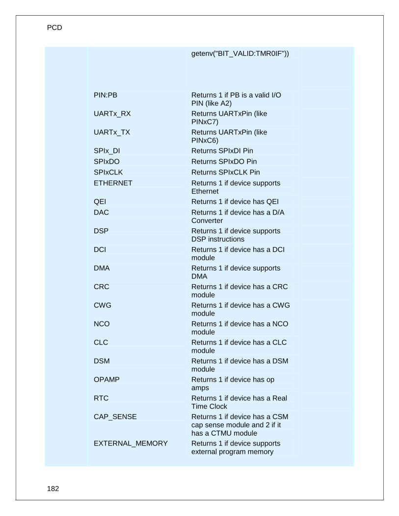
PCD
182
getenv("BIT_VALID:TMR0IF"))
PIN:PB Returns 1 if PB is a valid I/O PIN (like A2)
UARTx_RX Returns UARTxPin (like PINxC7)
UARTx_TX Returns UARTxPin (like PINxC6)
SPIx_DI Returns SPIxDI Pin
SPIxDO Returns SPIxDO Pin
SPIxCLK Returns SPIxCLK Pin
ETHERNET Returns 1 if device supports Ethernet
QEI Returns 1 if device has QEI
DAC Returns 1 if device has a D/A Converter
DSP Returns 1 if device supports DSP instructions
DCI Returns 1 if device has a DCI module
DMA Returns 1 if device supports DMA
CRC Returns 1 if device has a CRC module
CWG Returns 1 if device has a CWG module
NCO Returns 1 if device has a NCO module
CLC Returns 1 if device has a CLC module
DSM Returns 1 if device has a DSM module
OPAMP Returns 1 if device has op amps
RTC Returns 1 if device has a Real Time Clock
CAP_SENSE Returns 1 if device has a CSM cap sense module and 2 if it has a CTMU module
EXTERNAL_MEMORY Returns 1 if device supports external program memory

Built-in Functions
183
Availability: All devices
Requires: Nothing
Examples: #IF getenv("VERSION")<3.050
#ERROR Compiler version too old
#ENDIF
for(i=0;i<getenv("DATA_EEPROM");i++)
write_eeprom(i,0);
#IF getenv("FUSE_VALID:BROWNOUT")
#FUSE BROWNOUT
#ENDIF
#byte status_reg=GETENV(“SFR:STATUS”)
#bit carry_flag=GETENV(“BIT:C”)
Example Files:
None
Also See: None
gets( ) fgets( )
Syntax: gets (string) value = fgets (string, stream)
Parameters: string is a pointer to an array of characters. Stream is a stream identifier (a constant byte)
Returns: undefined
Function: Reads characters (using getc()) into the string until a RETURN (value 13) is encountered. The string is terminated with a 0. Note that INPUT.C has a more versatile get_string function. If fgets() is used then the specified stream is used where gets() defaults to STDIN (the last USE RS232).
Availability: All devices
Requires: #USE RS232
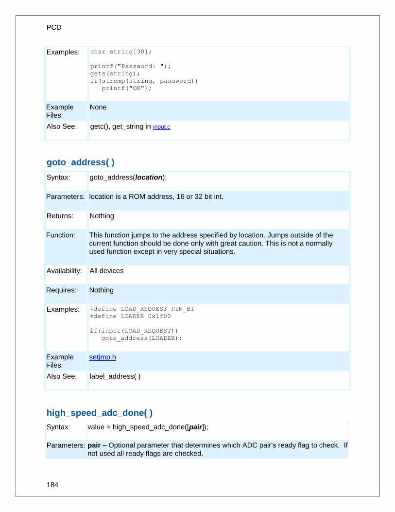
PCD
184
Examples: char string[30];
printf("Password: ");
gets(string);
if(strcmp(string, password))
printf("OK");
Example Files:
None
Also See: getc(), get_string in input.c
goto_address( )
Syntax: goto_address(location);
Parameters: location is a ROM address, 16 or 32 bit int.
Returns: Nothing
Function: This function jumps to the address specified by location. Jumps outside of the current function should be done only with great caution. This is not a normally used function except in very special situations.
Availability: All devices
Requires: Nothing
Examples: #define LOAD_REQUEST PIN_B1
#define LOADER 0x1f00
if(input(LOAD_REQUEST))
goto_address(LOADER);
Example Files:
setjmp.h
Also See: label_address( )
high_speed_adc_done( )
Syntax: value = high_speed_adc_done([pair]);
Parameters: pair – Optional parameter that determines which ADC pair's ready flag to check. If not used all ready flags are checked.

Built-in Functions
185
Returns: An int16. If pair is used 1 will be return if ADC is done with conversion, 0 will be return if still busy. If pair isn't use it will return a bit map of which conversion are ready to be read. For example a return value of 0x0041 means that ADC pair 6, AN12 and AN13, and ADC pair 0, AN0 and AN1, are ready to be read.
Function: Can be polled to determine if the ADC has valid data to be read.
Availability: Only on dsPIC33FJxxGSxxx devices.
Requires: None
Examples: int16 result[2]
setup_high_speed_adc_pair(1, INDIVIDUAL_SOFTWARE_TRIGGER);
setup_high_speed_adc( ADC_CLOCK_DIV_4);
read_high_speed_adc(1, ADC_START_ONLY);
while(!high_speed_adc_done(1));
read_high_speed_adc(1, ADC_READ_ONLY, result);
printf(“AN2 value = %LX, AN3 value = %LX\n\r”,result[0],result[1]);
Example Files:
None
Also See: setup_high_speed_adc(), setup_high_speed_adc_pair(), read_high_speed_adc()
i2c_init( )
Syntax: i2c_init([stream],baud);
Parameters: stream – optional parameter specifying the stream defined in #USE I2C. baud – if baud is 0, I2C peripheral will be disable. If baud is 1, I2C peripheral is initialized and enabled with baud rate specified in #USE I2C directive. If baud is > 1 then I2C peripheral is initialized and enabled to specified baud rate.
Returns: Nothing
Function: To initialize I2C peripheral at run time to specified baud rate.
Availability: All devices.
Requires: #USE I2C
Examples: #USE I2C(MASTER,I2C1, FAST,NOINIT) i2c_init(TRUE); //initialize and enable I2C peripheral to baud rate specified in //#USE I2C i2c_init(500000); //initialize and enable I2C peripheral to a baud rate of 500 //KBPS
Example Files:
None
Also See: I2C_POLL( ), i2c_speed( ), I2C_SlaveAddr( ), I2C_ISR_STATE(_) ,I2C_WRITE( ), I2C_READ( ), _USE_I2C( ), I2C( )

PCD
186
i2c_isr_state( )
Syntax: state = i2c_isr_state(); state = i2c_isr_state(stream);
Parameters: None
Returns: state is an 8 bit int 0 - Address match received with R/W bit clear, perform i2c_read( ) to read the I2C address. 1-0x7F - Master has written data; i2c_read() will immediately return the data 0x80 - Address match received with R/W bit set; perform i2c_read( ) to read the I2C address, and use i2c_write( ) to pre-load the transmit buffer for the next transaction (next I2C read performed by master will read this byte). 0x81-0xFF - Transmission completed and acknowledged; respond with i2c_write() to pre-load the transmit buffer for the next transation (the next I2C read performed by master will read this byte).
Function: Returns the state of I2C communications in I2C slave mode after an SSP interrupt. The return value increments with each byte received or sent. If 0x00 or 0x80 is returned, an i2C_read( ) needs to be performed to read the I2C address that was sent (it will match the address configured by #USE I2C so this value can be ignored)
Availability: Devices with i2c hardware
Requires: #USE I2C
Examples: #INT_SSP
void i2c_isr() {
state = i2c_isr_state();
if(state== 0 ) i2c_read();
i@c_read();
if(state == 0x80)
i2c_read(2);
if(state >= 0x80)
i2c_write(send_buffer[state - 0x80]);
else if(state > 0)
rcv_buffer[state - 1] = i2c_read();
}
Example Files:
ex_slave.c
Also See: i2c_poll, i2c_speed, i2c_start, i2c_stop, i2c_slaveaddr, i2c_write, i2c_read, #USE I2C, I2C Overview
i2c_poll( )
Syntax: i2c_poll() i2c_poll(stream)

Built-in Functions
187
Parameters: stream (optional)- specify the stream defined in #USE I2C
Returns: 1 (TRUE) or 0 (FALSE)
Function: The I2C_POLL() function should only be used when the built-in SSP is used. This function returns TRUE if the hardware has a received byte in the buffer. When a TRUE is returned, a call to I2C_READ() will immediately return the byte that was received.
Availability: Devices with built in I2C
Requires: #USE I2C
Examples: if(i2c-poll())
buffer [index]=i2c-read();//read data
Example Files:
None
Also See: i2c_speed, i2c_start, i2c_stop, i2c_slaveaddr, i2c_isr_state, i2c_write, i2c_read, #USE I2C, I2C Overview
i2c_read( )
Syntax: data = i2c_read(); data = i2c_read(ack); data = i2c_read(stream, ack);
Parameters: ack -Optional, defaults to 1. 0 indicates do not ack. 1 indicates to ack. 2 slave only, indicates to not release clock at end of read. Use when i2c_isr_state () returns 0x80. stream - specify the stream defined in #USE I2C
Returns: data - 8 bit int
Function: Reads a byte over the I2C interface. In master mode this function will generate the clock and in slave mode it will wait for the clock. There is no timeout for the slave, use i2c_poll() to prevent a lockup. Use restart_wdt() in the #USE I2C to strobe the watch-dog timer in the slave mode while waiting.
Availability: All devices.
Requires: #USE I2C
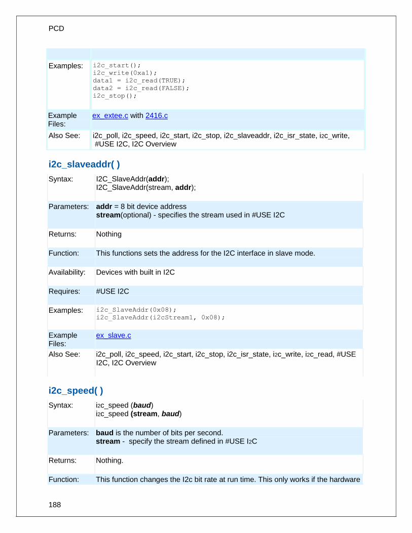
PCD
188
Examples: i2c_start();
i2c_write(0xa1);
data1 = i2c_read(TRUE);
data2 = i2c_read(FALSE);
i2c_stop();
Example Files:
ex_extee.c with 2416.c
Also See: i2c_poll, i2c_speed, i2c_start, i2c_stop, i2c_slaveaddr, i2c_isr_state, i2c_write, #USE I2C, I2C Overview
i2c_slaveaddr( )
Syntax: I2C_SlaveAddr(addr); I2C_SlaveAddr(stream, addr);
Parameters: addr = 8 bit device address stream(optional) - specifies the stream used in #USE I2C
Returns: Nothing
Function: This functions sets the address for the I2C interface in slave mode.
Availability: Devices with built in I2C
Requires: #USE I2C
Examples: i2c_SlaveAddr(0x08);
i2c_SlaveAddr(i2cStream1, 0x08);
Example Files:
ex_slave.c
Also See: i2c_poll, i2c_speed, i2c_start, i2c_stop, i2c_isr_state, i2c_write, i2c_read, #USE I2C, I2C Overview
i2c_speed( )
Syntax: i2c_speed (baud) i2c_speed (stream, baud)
Parameters: baud is the number of bits per second. stream - specify the stream defined in #USE I2C
Returns: Nothing.
Function: This function changes the I2c bit rate at run time. This only works if the hardware

Built-in Functions
189
I2C module is being used.
Availability: All devices.
Requires: #USE I2C
Examples: I2C_Speed (400000);
Example Files:
none
Also See: i2c_poll, i2c_start, i2c_stop, i2c_slaveaddr, i2c_isr_state, i2c_write, i2c_read, #USE I2C, I2C Overview
i2c_start( )
Syntax: i2c_start() i2c_start(stream) i2c_start(stream, restart)
Parameters: stream: specify the stream defined in #USE I2C restart: 2 – new restart is forced instead of start 1 – normal start is performed 0 (or not specified) – restart is done only if the compiler last encountered a I2C_START and no I2C_STOP
Returns: undefined
Function: Issues a start condition when in the I2C master mode. After the start condition the clock is held low until I2C_WRITE() is called. If another I2C_start is called in the same function before an i2c_stop is called, then a special restart condition is issued. Note that specific I2C protocol depends on the slave device. The I2C_START function will now accept an optional parameter. If 1 the compiler assumes the bus is in the stopped state. If 2 the compiler treats this I2C_START as a restart. If no parameter is passed a 2 is used only if the compiler compiled a I2C_START last with no I2C_STOP since.
Availability: All devices.
Requires: #USE I2C
Examples: i2c_start();
i2c_write(0xa0); // Device address
i2c_write(address); // Data to device
i2c_start(); // Restart
i2c_write(0xa1); // to change data direction

PCD
190
data=i2c_read(0); // Now read from slave
i2c_stop();
Example Files:
ex_extee.c with 2416.c
Also See: i2c_poll, i2c_speed, i2c_stop, i2c_slaveaddr, i2c_isr_state, i2c_write, i2c_read, #USE I2C, I2C Overview
i2c_stop( )
Syntax: i2c_stop() i2c_stop(stream)
Parameters: stream: (optional) specify stream defined in #USE I2C
Returns: undefined
Function: Issues a stop condition when in the I2C master mode.
Availability: All devices.
Requires: #USE I2C
Examples: i2c_start(); // Start condition
i2c_write(0xa0); // Device address
i2c_write(5); // Device command
i2c_write(12); // Device data
i2c_stop(); // Stop condition
Example Files:
ex_extee.c with 2416.c
Also See: i2c_poll, i2c_speed, i2c_start, i2c_slaveaddr, i2c_isr_state, i2c_write, i2c_read, #USE I2C, I2C Overview
i2c_write( )
Syntax: i2c_write (data) i2c_write (stream, data)
Parameters: data is an 8 bit int stream - specify the stream defined in #USE I2C
Returns: This function returns the ACK Bit.

Built-in Functions
191
0 means ACK, 1 means NO ACK, 2 means there was a collision if in Multi_Master Mode. This does not return an ACK if using i2c in slave mode.
Function: Sends a single byte over the I2C interface. In master mode this function will generate a clock with the data and in slave mode it will wait for the clock from the master. No automatic timeout is provided in this function. This function returns the ACK bit. The LSB of the first write after a start determines the direction of data transfer (0 is master to slave). Note that specific I2C protocol depends on the slave device.
Availability: All devices.
Requires: #USE I2C
Examples: long cmd;
...
i2c_start(); // Start condition
i2c_write(0xa0);// Device address
i2c_write(cmd);// Low byte of command
i2c_write(cmd>>8);// High byte of command
i2c_stop(); // Stop condition
Example Files:
ex_extee.c with 2416.c
Also See: i2c_poll, i2c_speed, i2c_start, i2c_stop, i2c_slaveaddr, i2c_isr_state, i2c_read, #USE I2C, I2C Overview
input( )
Syntax: value = input (pin)
Parameters: Pin to read. Pins are defined in the devices .h file. The actual value is a bit address. For example, port a (byte 5 ) bit 3 would have a value of 5*8+3 or 43 . This is defined as follows: #define PIN_A3 43 . The PIN could also be a variable. The variable must have a value equal to one of the constants (like PIN_A1) to work properly. The tristate register is updated unless the FAST_IO mode is set on port A. note that doing I/O with a variable instead of a constant will take much longer time.
Returns: 0 (or FALSE) if the pin is low, 1 (or TRUE) if the pin is high
Function: This function returns the state of the indicated pin. The method of I/O is dependent on the last USE *_IO directive. By default with standard I/O before the input is done the data direction is set to input.

PCD
192
Availability: All devices.
Requires: Pin constants are defined in the devices .h file
Examples: while ( !input(PIN_B1) );
// waits for B1 to go high
if( input(PIN_A0) )
printf("A0 is now high\r\n");
int16 i=PIN_B1;
while(!i);
//waits for B1 to go high
Example Files:
ex_pulse.c
Also See: input_x(), output_low(), output_high(), #USE FIXED_IO, #USE FAST_IO, #USE STANDARD_IO, General Purpose I/O
input_change_x( )
Syntax: value = input_change_a( ); value = input_change_b( ); value = input_change_c( ); value = input_change_d( ); value = input_change_e( ); value = input_change_f( ); value = input_change_g( ); value = input_change_h( ); value = input_change_j( ); value = input_change_k( );
Parameters: None
Returns: An 8-bit or 16-bit int representing the changes on the port.
Function: This function reads the level of the pins on the port and compares them to the results the last time the input_change_x( ) function was called. A 1 is returned if the value has changed, 0 if the value is unchanged.
Availability: All devices.
Requires: None
Examples: pin_check = input_change_b( );
Example None

Built-in Functions
193
Files:
Also See: input( ), input_x( ), output_x( ), #USE FIXED_IO, #USE FAST_IO, #USE STANDARD_IO, General Purpose I/O
input_state( )
Syntax: value = input_state(pin)
Parameters: pin to read. Pins are defined in the devices .h file. The actual value is a bit address. For example, port a (byte 5 ) bit 3 would have a value of 5*8+3 or 43 . This is defined as follows: #define PIN_A3 43 .
Returns: Bit specifying whether pin is high or low. A 1 indicates the pin is high and a 0 indicates it is low.
Function: This function reads the level of a pin without changing the direction of the pin as INPUT() does.
Availability: All devices.
Requires: Nothing
Examples: level = input_state(pin_A3);
printf("level: %d",level);
Example Files:
None
Also See: input(), set_tris_x(), output_low(), output_high(), General Purpose I/O
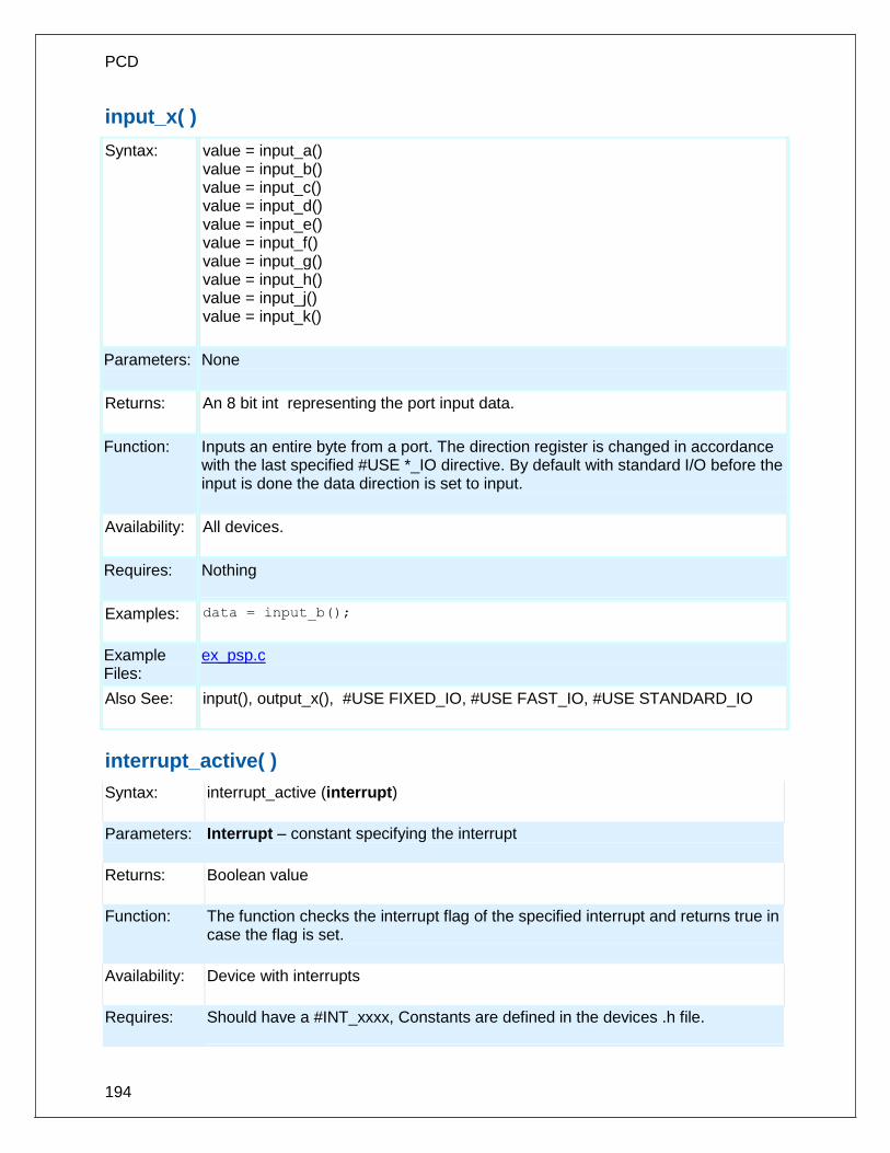
PCD
194
input_x( )
Syntax: value = input_a() value = input_b() value = input_c() value = input_d() value = input_e() value = input_f() value = input_g() value = input_h() value = input_j() value = input_k()
Parameters: None
Returns: An 8 bit int representing the port input data.
Function: Inputs an entire byte from a port. The direction register is changed in accordance with the last specified #USE *_IO directive. By default with standard I/O before the input is done the data direction is set to input.
Availability: All devices.
Requires: Nothing
Examples: data = input_b();
Example Files:
ex_psp.c
Also See: input(), output_x(), #USE FIXED_IO, #USE FAST_IO, #USE STANDARD_IO
interrupt_active( )
Syntax: interrupt_active (interrupt)
Parameters: Interrupt – constant specifying the interrupt
Returns: Boolean value
Function: The function checks the interrupt flag of the specified interrupt and returns true in case the flag is set.
Availability: Device with interrupts
Requires: Should have a #INT_xxxx, Constants are defined in the devices .h file.

Built-in Functions
195
Examples: interrupt_active(INT_TIMER0);
interrupt_active(INT_TIMER1);
Example Files:
None
Also See: disable_interrupts() , #INT , Interrupts Overview clear_interrupt, enable_interrupts()
isalnum(char) isalpha(char) isdigit(char) islower(char) isspace(char) isupper(char) isxdigit(char) iscntrl(x) isgraph(x) isprint(x) ispunct(x)
Syntax: value = isalnum(datac) value = isalpha(datac) value = isdigit(datac) value = islower(datac) value = isspace(datac) value = isupper(datac) value = isxdigit(datac) value = iscntrl(datac) value = isgraph(datac) value = isprint(datac) value = punct(datac)
Parameters: datac is a 8 bit character
Returns: 0 (or FALSE) if datac dose not match the criteria, 1 (or TRUE) if datac does match the criteria.
Function: Tests a character to see if it meets specific criteria as follows:
isalnum(x) X is 0..9, 'A'..'Z', or 'a'..'z'
isalpha(x) X is 'A'..'Z' or 'a'..'z
isdigit(x) X is '0'..'9'
islower(x) X is 'a'..'z'
isupper(x) X is 'A'..'Z
isspace(x) X is a space
isxdigit(x) X is '0'..'9', 'A'..'F', or 'a'..'f
iscntrl(x) X is less than a space
isgraph(x) X is greater than a space
isprint(x) X is greater than or equal to a space
ispunct(x) X is greater than a space and not a letter or number
Availability: All devices.
Requires: #INCLUDE <ctype.h>

PCD
196
Examples: char id[20];
...
if(isalpha(id[0])) {
valid_id=TRUE;
for(i=1;i<strlen(id);i++)
valid_id=valid_id && isalnum(id[i]);
} else
valid_id=FALSE;
Example Files:
ex_str.c
Also See: isamong()
isamong( )
Syntax: result = isamong (value, cstring)
Parameters: value is a character cstring is a constant sting
Returns: 0 (or FALSE) if value is not in cstring 1 (or TRUE) if value is in cstring
Function: Returns TRUE if a character is one of the characters in a constant string.
Availability: All devices
Requires: Nothing
Examples: char x= 'x';
...
if ( isamong ( x,
"0123456789ABCDEFGHIJKLMNOPQRSTUVWXYZ") )
printf ("The character is valid");
Example Files: #INCLUDE <ctype.h>
Also See: isalnum( ), isalpha( ), isdigit( ), isspace( ), islower( ), isupper( ), isxdigit( )

Built-in Functions
197
itoa( )
Syntax: string = itoa(i32value, i8base, string)
Parameters: i32value is a 32 bit int i8base is a 8 bit int string is a pointer to a null terminated string of characters
Returns: string is a pointer to a null terminated string of characters
Function: Converts the signed int32 to a string according to the provided base and returns the converted value if any. If the result cannot be represented, the function will return 0.
Availability: All devices
Requires: #INCLUDE <stdlib.h>
Examples: int32 x=1234;
char string[5];
itoa(x,10, string);
// string is now “1234”
Example Files:
None
Also See: None
jump_to_isr( )
Syntax: jump_to_isr (address)
Parameters: address is a valid program memory address
Returns: No value
Function: The jump_to_isr function is used when the location of the interrupt service routines are not at the default location in program memory. When an interrupt occurs, program execution will jump to the default location and then jump to the specified address.
Availability: All devices
Requires: Nothing
Examples: int_global
void global_isr(void) {

PCD
198
jump_to_isr(isr_address);
}
Example Files:
ex_bootloader.c
Also See: #BUILD
kbhit( )
Syntax: value = kbhit() value = kbhit (stream)
Parameters: stream is the stream id assigned to an available RS232 port. If the stream parameter is not included, the function uses the primary stream used by getc().
Returns: 0 (or FALSE) if getc() will need to wait for a character to come in, 1 (or TRUE) if a character is ready for getc()
Function: If the RS232 is under software control this function returns TRUE if the start bit of a character is being sent on the RS232 RCV pin. If the RS232 is hardware this function returns TRUE if a character has been received and is waiting in the hardware buffer for getc() to read. This function may be used to poll for data without stopping and waiting for the data to appear. Note that in the case of software RS232 this function should be called at least 10 times the bit rate to ensure incoming data is not lost.
Availability: All devices.
Requires: #USE RS232
Examples: char timed_getc() {
long timeout;
timeout_error=FALSE;
timeout=0;
while(!kbhit()&&(++timeout<50000)) // 1/2
// second
delay_us(10);
if(kbhit())
return(getc());
else {
timeout_error=TRUE;
return(0);
}
}
Example ex_tgetc.c

Built-in Functions
199
Files:
Also See: getc(), #USE RS232, RS232 I/O Overview
label_address( )
Syntax: value = label_address(label);
Parameters: label is a C label anywhere in the function
Returns: A 16 bit int in PCB,PCM and a 32 bit int for PCH, PCD
Function: This function obtains the address in ROM of the next instruction after the label. This is not a normally used function except in very special situations.
Availability: All devices.
Requires: Nothing
Examples: start:
a = (b+c)<<2;
end:
printf("It takes %lu ROM locations.\r\n",
label_address(end)-label_address(start));
Example Files:
setjmp.h
Also See: goto_address()
labs( )
Syntax: result = labs (value)
Parameters: value is a 16 bit signed long int
Returns: A 16 bit signed long int
Function: Computes the absolute value of a long integer.
Availability: All devices.
Requires: #INCLUDE <stdlib.h>
Examples: if(labs( target_value - actual_value ) > 500)

PCD
200
printf("Error is over 500 points\r\n");
Example Files: None
Also See: abs()
lcd_contrast( )
Syntax: lcd_contrast ( contrast )
Parameters: contrast is used to set the internal contrast control resistance ladder.
Returns: undefined.
Function: This function controls the contrast of the LCD segments with a value passed in between 0 and 7. A value of 0 will produce the minimum contrast, 7 will produce the maximum contrast.
Availability: Only on select devices with built-in LCD Driver Module hardware.
Requires: None.
Examples: lcd_contrast( 0 ); // Minimum Contrast
lcd_contrast( 7 ); // Maximum Contrast
Example Files:
None.
Also See: lcd_load( ), lcd_symbol( ), setup_lcd( ), Internal LCD Overview
lcd_load( )
Syntax: lcd_load (buffer_pointer, offset, length);
Parameters: buffer_pointer points to the user data to send to the LCD, offset is the offset into the LCD segment memory to write the data, length is the number of bytes to transfer to the LCD segment memory.
Returns: undefined.
Function: This function will load length bytes from buffer_pointer into the LCD segment memory beginning at offset. The lcd_symbol( ) function provides as easier way to write data to the segment memory.

Built-in Functions
201
Availability: Only on devices with built-in LCD Driver Module hardware.
Requires Constants are defined in the devices *.h file.
Examples: lcd_load(buffer, 0, 16);
Example Files:
ex_92lcd.c
Also See: lcd_symbol(), setup_lcd(), lcd_contrast( ), Internal LCD Overview
lcd_symbol( )
Syntax: lcd_symbol (symbol, bX_addr);
Parameters: symbol is a 8 bit or 16 bit constant. bX_addr is a bit address representing the segment location to be used for bit X of the specified symbol. 1-16 segments could be specified.
Returns: undefined
Function: This function loads the bits for the symbol into the segment data registers for the LCD with each bit address specified. If bit X in symbol is set, the segment at bX_addr is set, otherwise it is cleared. The bX_addr is a bit address into the LCD RAM.
Availability: Only on devices with built-in LCD Driver Module hardware.
Requires Constants are defined in the devices *.h file.
Examples: byte CONST DIGIT_MAP[10] = {0xFC, 0x60, 0xDA, 0xF2, 0x66, 0xB6, 0xBE, 0xE0, 0xFE, 0xE6};
#define DIGIT1 COM1+20, COM1+18, COM2+18, COM3+20, COM2+28, COM1+28, COM2+20, COM3+18
for(i = 0; i <= 9; i++) {
lcd_symbol( DIGIT_MAP[i], DIGIT1 );
delay_ms( 1000 );
}
Example Files:
ex_92lcd.c
Also See: setup_lcd(), lcd_load(), lcd_contrast( ), Internal LCD Overview

PCD
202
ldexp( )
Syntax: result= ldexp (value, exp);
Parameters: value is float exp is a signed int.
Returns: result is a float with value result times 2 raised to power exp.
Function: The ldexp function multiplies a floating-point number by an integral power of 2.
Availability: All devices.
Requires: #INCLUDE <math.h>
Examples: float result;
result=ldexp(.5,0);
// result is .5
Example Files:
None
Also See: frexp(), exp(), log(), log10(), modf()
log( )
Syntax: result = log (value)
Parameters: value is a float
Returns: A float
Function: Computes the natural logarithm of the float x. If the argument is less than or equal to zero or too large, the behavior is undefined. Note on error handling: "errno.h" is included then the domain and range errors are stored in the errno variable. The user can check the errno to see if an error has occurred and print the error using the perror function. Domain error occurs in the following cases:
log: when the argument is negative
Availability: All devices

Built-in Functions
203
Requires: #INCLUDE <math.h>
Examples: lnx = log(x);
Example Files:
None
Also See: log10(), exp(), pow()
log10( )
Syntax: result = log10 (value)
Parameters: value is a float
Returns: A float
Function: Computes the base-ten logarithm of the float x. If the argument is less than or equal to zero or too large, the behavior is undefined. Note on error handling: If "errno.h" is included then the domain and range errors are stored in the errno variable. The user can check the errno to see if an error has occurred and print the error using the perror function. Domain error occurs in the following cases:
log10: when the argument is negative
Availability: All devices
Requires: #INCLUDE <math.h>
Examples: db = log10( read_adc()*(5.0/255) )*10;
Example Files:
None
Also See: log(), exp(), pow()
longjmp( )
Syntax: longjmp (env, val)
Parameters: env: The data object that will be restored by this function val: The value that the function setjmp will return. If val is 0 then the function

PCD
204
setjmp will return 1 instead.
Returns: After longjmp is completed, program execution continues as if the corresponding invocation of the setjmp function had just returned the value specified by val.
Function: Performs the non-local transfer of control.
Availability: All devices
Requires: #INCLUDE <setjmp.h>
Examples: longjmp(jmpbuf, 1);
Example Files:
None
Also See: setjmp()
make8( )
Syntax: i8 = MAKE8(var, offset)
Parameters: var is a 16 or 32 bit integer. offset is a byte offset of 0,1,2 or 3.
Returns: An 8 bit integer
Function: Extracts the byte at offset from var. Same as: i8 = (((var >> (offset*8)) & 0xff) except it is done with a single byte move.
Availability: All devices
Requires: Nothing
Examples: int32 x;
int y;
y = make8(x,3); // Gets MSB of x
Example Files:
None
Also See: make16(), make32()

Built-in Functions
205
make16( )
Syntax: i16 = MAKE16(varhigh, varlow)
Parameters: varhigh and varlow are 8 bit integers.
Returns: A 16 bit integer
Function: Makes a 16 bit number out of two 8 bit numbers. If either parameter is 16 or 32 bits only the lsb is used. Same as: i16 = (int16)(varhigh&0xff)*0x100+(varlow&0xff) except it is done with two byte moves.
Availability: All devices
Requires: Nothing
Examples: long x;
int hi,lo;
x = make16(hi,lo);
Example Files:
ltc1298.c
Also See: make8(), make32()
make32( )
Syntax: i32 = MAKE32(var1, var2, var3, var4)
Parameters: var1-4 are a 8 or 16 bit integers. var2-4 are optional.
Returns: A 32 bit integer
Function: Makes a 32 bit number out of any combination of 8 and 16 bit numbers. Note that the number of parameters may be 1 to 4. The msb is first. If the total bits provided is less than 32 then zeros are added at the msb.
Availability: All devices
Requires: Nothing
Examples: int32 x;
int y;
long z;
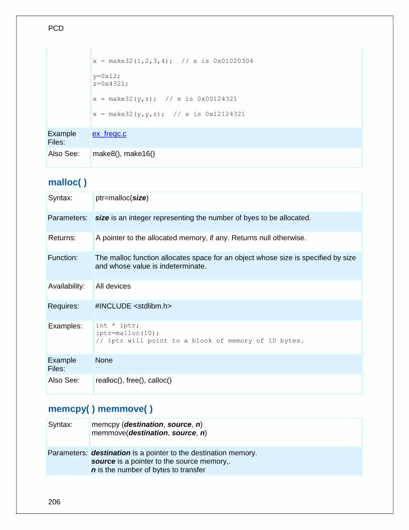
PCD
206
x = make32(1,2,3,4); // x is 0x01020304
y=0x12;
z=0x4321;
x = make32(y,z); // x is 0x00124321
x = make32(y,y,z); // x is 0x12124321
Example Files:
ex_freqc.c
Also See: make8(), make16()
malloc( )
Syntax: ptr=malloc(size)
Parameters: size is an integer representing the number of byes to be allocated.
Returns: A pointer to the allocated memory, if any. Returns null otherwise.
Function: The malloc function allocates space for an object whose size is specified by size and whose value is indeterminate.
Availability: All devices
Requires: #INCLUDE <stdlibm.h>
Examples: int * iptr;
iptr=malloc(10);
// iptr will point to a block of memory of 10 bytes.
Example Files:
None
Also See: realloc(), free(), calloc()
memcpy( ) memmove( )
Syntax: memcpy (destination, source, n) memmove(destination, source, n)
Parameters: destination is a pointer to the destination memory. source is a pointer to the source memory,. n is the number of bytes to transfer
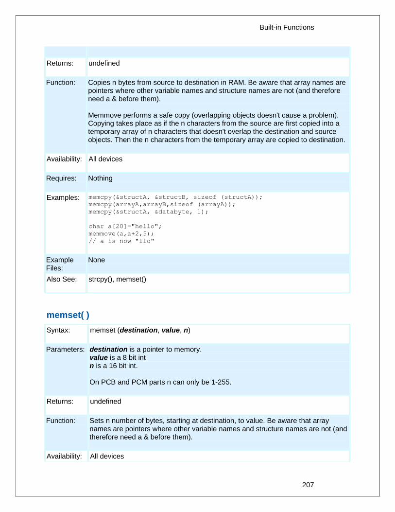
Built-in Functions
207
Returns: undefined
Function: Copies n bytes from source to destination in RAM. Be aware that array names are pointers where other variable names and structure names are not (and therefore need a & before them). Memmove performs a safe copy (overlapping objects doesn't cause a problem). Copying takes place as if the n characters from the source are first copied into a temporary array of n characters that doesn't overlap the destination and source objects. Then the n characters from the temporary array are copied to destination.
Availability: All devices
Requires: Nothing
Examples: memcpy(&structA, &structB, sizeof (structA));
memcpy(arrayA,arrayB,sizeof (arrayA));
memcpy(&structA, &databyte, 1);
char a[20]="hello";
memmove(a,a+2,5);
// a is now "llo"
Example Files:
None
Also See: strcpy(), memset()
memset( )
Syntax: memset (destination, value, n)
Parameters: destination is a pointer to memory. value is a 8 bit int n is a 16 bit int. On PCB and PCM parts n can only be 1-255.
Returns: undefined
Function: Sets n number of bytes, starting at destination, to value. Be aware that array names are pointers where other variable names and structure names are not (and therefore need a & before them).
Availability: All devices

PCD
208
Requires: Nothing
Examples: memset(arrayA, 0, sizeof(arrayA));
memset(arrayB, '?', sizeof(arrayB));
memset(&structA, 0xFF, sizeof(structA));
Example Files:
None
Also See: memcpy()
modf( )
Syntax: result= modf (value, & integral)
Parameters: value is a float integral is a float
Returns: result is a float
Function: The modf function breaks the argument value into integral and fractional parts, each of which has the same sign as the argument. It stores the integral part as a float in the object integral.
Availability: All devices
Requires: #INCLUDE <math.h>
Examples: float result, integral;
result=modf(123.987,&integral);
// result is .987 and integral is 123.0000
Example Files:
None
Also See: None
_mul( )
Syntax: prod=_mul(val1, val2);
Parameters: val1 and val2 are both 8-bit or 16-bit integers
Returns: A 16-bit integer if both parameters are 8-bit integers, or a 32-bit integer if both parameters are 16-bit integers.

Built-in Functions
209
Function: Performs an optimized multiplication. By accepting a different type than it returns, this function avoids the overhead of converting the parameters to a larger type.
Availability: All devices
Requires: Nothing
Examples: int a=50, b=100;
long int c;
c = _mul(a, b); //c holds 5000
Example Files:
None
Also See: None
nargs( )
Syntax: void foo(char * str, int count, ...)
Parameters: The function can take variable parameters. The user can use stdarg library to create functions that take variable parameters.
Returns: Function dependent.
Function: The stdarg library allows the user to create functions that supports variable arguments. The function that will accept a variable number of arguments must have at least one actual, known parameters, and it may have more. The number of arguments is often passed to the function in one of its actual parameters. If the variable-length argument list can involve more that one type, the type information is generally passed as well. Before processing can begin, the function creates a special argument pointer of type va_list.
Availability: All devices
Requires: #INCLUDE <stdarg.h>
Examples: int foo(int num, ...)
{
int sum = 0;
int i;
va_list argptr; // create special argument pointer
va_start(argptr,num); // initialize argptr
for(i=0; i<num; i++)
sum = sum + va_arg(argptr, int);
va_end(argptr); // end variable processing

PCD
210
return sum;
}
void main()
{
int total;
total = foo(2,4,6,9,10,2);
}
Example Files:
None
Also See: va_start( ) , va_end( ) , va_arg( )
offsetof( ) offsetofbit( )
Syntax: value = offsetof(stype, field); value = offsetofbit(stype, field);
Parameters: stype is a structure type name. Field is a field from the above structure
Returns: An 8 bit byte
Function: These functions return an offset into a structure for the indicated field. offsetof returns the offset in bytes and offsetofbit returns the offset in bits.
Availability: All devices
Requires: #INCLUDE <stddef.h>
Examples: struct time_structure {
int hour, min, sec;
int zone : 4;
intl daylight_savings;
}
x = offsetof(time_structure, sec);
// x will be 2
x = offsetofbit(time_structure, sec);
// x will be 16
x = offsetof (time_structure,
daylight_savings);
// x will be 3
x = offsetofbit(time_structure,
daylight_savings);
// x will be 28

Built-in Functions
211
Example Files: None
Also See: None
output_x( )
Syntax: output_a (value) output_b (value) output_c (value) output_d (value) output_e (value) output_f (value) output_g (value) output_h (value) output_j (value) output_k (value)
Parameters: value is a 8 bit int
Returns: undefined
Function: Output an entire byte to a port. The direction register is changed in accordance with the last specified #USE *_IO directive.
Availability: All devices, however not all devices have all ports (A-E)
Requires: Nothing
Examples: OUTPUT_B(0xf0);
Example Files:
ex_patg.c
Also See: input(), output_low(), output_high(), output_float(), output_bit(), #USE FIXED_IO, #USE FAST_IO, #USE STANDARD_IO, General Purpose I/O
output_bit( )
Syntax: output_bit (pin, value)
Parameters: Pins are defined in the devices .h file. The actual number is a bit address. For example, port a (byte 5 ) bit 3 would have a value of 5*8+3 or 43 . This is defined as follows: #define PIN_A3 43 . The PIN could also be a variable. The variable

PCD
212
must have a value equal to one of the constants (like PIN_A1) to work properly. The tristate register is updated unless the FAST_IO mode is set on port A. Note that doing I/O with a variable instead of a constant will take much longer time. Value is a 1 or a 0.
Returns: undefined
Function: Outputs the specified value (0 or 1) to the specified I/O pin. The method of setting the direction register is determined by the last #USE *_IO directive.
Availability: All devices.
Requires: Pin constants are defined in the devices .h file
Examples: output_bit( PIN_B0, 0);
// Same as output_low(pin_B0);
output_bit( PIN_B0,input( PIN_B1 ) );
// Make pin B0 the same as B1
output_bit( PIN_B0,shift_left(&data,1,input(PIN_B1)));
// Output the MSB of data to
// B0 and at the same time
// shift B1 into the LSB of data
int16 i=PIN_B0;
ouput_bit(i,shift_left(&data,1,input(PIN_B1)));
//same as above example, but
//uses a variable instead of a constant
Example Files:
ex_extee.c with 9356.c
Also See: input(), output_low(), output_high(), output_float(), output_x(), #USE FIXED_IO, #USE FAST_IO, #USE STANDARD_IO, General Purpose I/O
output_drive( )
Syntax: output_drive(pin)
Parameters: Pins are defined in the devices .h file. The actual value is a bit address. For example, port a (byte 5 ) bit 3 would have a value of 5*8+3 or 43 . This is defined as follows: #DEFINE PIN_A3 43 .
Returns: undefined
Function: Sets the specified pin to the output mode.

Built-in Functions
213
Availability: All devices.
Requires: Pin constants are defined in the devices.h file.
Examples: output_drive(pin_A0); // sets pin_A0 to output its value
output_bit(pin_B0, input(pin_A0)) // makes B0 the same as A0
Example Files:
None
Also See: input(), output_low(), output_high(), output_bit(), output_x(), output_float()
.
output_float( )
Syntax: output_float (pin)
Parameters: Pins are defined in the devices .h file. The actual value is a bit address. For example, port a (byte 5 ) bit 3 would have a value of 5*8+3 or 43 . This is defined as follows: #DEFINE PIN_A3 43 . The PIN could also be a variable to identify the pin. The variable must have a value equal to one of the constants (like PIN_A1) to work properly. Note that doing I/O with a variable instead of a constant will take much longer time.
Returns: undefined
Function: Sets the specified pin to the input mode. This will allow the pin to float high to represent a high on an open collector type of connection.
Availability: All devices.
Requires: Pin constants are defined in the devices .h file
Examples: if( (data & 0x80)==0 )
output_low(pin_A0);
else
output_float(pin_A0);
Example Files:
None
Also See: input(), output_low(), output_high(), output_bit(), output_x(), output_drive(), #USE FIXED_IO, #USE FAST_IO, #USE STANDARD_IO, General Purpose I/O

PCD
214
output_high( )
Syntax: output_high (pin)
Parameters: Pin to write to. Pins are defined in the devices .h file. The actual value is a bit address. For example, port a (byte 5 ) bit 3 would have a value of 5*8+3 or 43 . This is defined as follows: #DEFINE PIN_A3 43 . The PIN could also be a variable. The variable must have a value equal to one of the constants (like PIN_A1) to work properly. The tristate register is updated unless the FAST_IO mode is set on port A. Note that doing I/O with a variable instead of a constant will take much longer time.
Returns: undefined
Function: Sets a given pin to the high state. The method of I/O used is dependent on the last USE *_IO directive.
Availability: All devices.
Requires: Pin constants are defined in the devices .h file
Examples: output_high(PIN_A0);
Int16 i=PIN_A1;
output_low(PIN_A1);
Example Files:
ex_sqw.c
Also See: input(), output_low(), output_float(), output_bit(), output_x(), #USE FIXED_IO, #USE FAST_IO, #USE STANDARD_IO, General Purpose I/O
output_low( )
Syntax: output_low (pin)
Parameters: Pins are defined in the devices .h file. The actual value is a bit address. For example, port a (byte 5 ) bit 3 would have a value of 5*8+3 or 43 . This is defined as follows: #DEFINE PIN_A3 43 . The PIN could also be a variable. The variable must have a value equal to one of the constants (like PIN_A1) to work properly. The tristate register is updated unless the FAST_IO mode is set on port A. Note that doing I/O with a variable instead of a constant will take much longer time.
Returns: undefined
Function: Sets a given pin to the ground state. The method of I/O used is dependent on the last USE *_IO directive.

Built-in Functions
215
Availability: All devices.
Requires: Pin constants are defined in the devices .h file
Examples: output_low(PIN_A0);
Int16i=PIN_A1;
output_low(PIN_A1);
Example Files:
ex_sqw.c
Also See: input(), output_high(), output_float(), output_bit(), output_x(), #USE FIXED_IO, #USE FAST_IO, #USE STANDARD_IO, General Purpose I/O
output_toggle( )
Syntax: output_toggle(pin)
Parameters: Pins are defined in the devices .h file. The actual value is a bit address. For example, port a (byte 5 ) bit 3 would have a value of 5*8+3 or 43 . This is defined as follows: #DEFINE PIN_A3 43 .
Returns: Undefined
Function: Toggles the high/low state of the specified pin.
Availability: All devices.
Requires: Pin constants are defined in the devices .h file
Examples: output_toggle(PIN_B4);
Example Files:
None
Also See: Input(), output_high(), output_low(), output_bit(), output_x()
perror( )
Syntax: perror(string);
Parameters: string is a constant string or array of characters (null terminated).
Returns: Nothing

PCD
216
Function: This function prints out to STDERR the supplied string and a description of the last system error (usually a math error).
Availability: All devices.
Requires: #USE RS232, #INCLUDE <errno.h>
Examples: x = sin(y);
if(errno!=0)
perror("Problem in find_area");
Example Files:
None
Also See: RS232 I/O Overview
port_x_pullups ( )
Syntax: port_a_pullups (value) port_b_pullups (value) port_d_pullups (value) port_e_pullups (value) port_j_pullups (value) port_x_pullups (upmask) port_x_pullups (upmask, downmask)
Parameters: value is TRUE or FALSE on most parts, some parts that allow pullups to be specified on individual pins permit an 8 bit int here, one bit for each port pin. upmask for ports that permit pullups to be specified on a pin basis. This mask indicates what pins should have pullups activated. A 1 indicates the pullups is on. downmask for ports that permit pulldowns to be specified on a pin basis. This mask indicates what pins should have pulldowns activated. A 1 indicates the pulldowns is on.
Returns: undefined
Function: Sets the input pullups. TRUE will activate, and a FALSE will deactivate.
Availability: Only 14 and 16 bit devices (PCM and PCH). (Note: use SETUP_COUNTERS on PCB parts).
Requires: Nothing
Examples: port_a_pullups(FALSE);
Example ex_lcdkb.c, kbd.c

Built-in Functions
217
Files:
Also See: input(), input_x(), output_float()
pow( ) pwr( )
Syntax: f = pow (x,y) f = pwr (x,y)
Parameters: x and y are of type float
Returns: A float
Function: Calculates X to the Y power. Note on error handling: If "errno.h" is included then the domain and range errors are stored in the errno variable. The user can check the errno to see if an error has occurred and print the error using the perror function. Range error occurs in the following case:
pow: when the argument X is negative
Availability: All Devices
Requires: #INCLUDE <math.h>
Examples: area = pow (size,3.0);
Example Files:
None
Also See: None
printf( ) fprintf( )
Syntax: printf (string) or printf (cstring, values...) or printf (fname, cstring, values...) fprintf (stream, cstring, values...)
Parameters: String is a constant string or an array of characters null terminated. Values is a list of variables separated by commas, fname is a function name to be

PCD
218
used for outputting (default is putc is none is specified. Stream is a stream identifier (a constant byte). Note that format specifies do not work in ram band strings.
Returns: undefined
Function: Outputs a string of characters to either the standard RS-232 pins (first two forms) or to a specified function. Formatting is in accordance with the string argument. When variables are used this string must be a constant. The % character is used within the string to indicate a variable value is to be formatted and output. Longs in the printf may be 16 or 32 bit. A %% will output a single %. Formatting rules for the % follows. See the Expressions > Constants and Trigraph sections of this manual for other escape character that may be part of the string. If fprintf() is used then the specified stream is used where printf() defaults to STDOUT (the last USE RS232). Format: The format takes the generic form %nt. n is optional and may be 1-9 to specify how many characters are to be outputted, or 01-09 to indicate leading zeros, or 1.1 to 9.9 for floating point and %w output. t is the type and may be one of the following:
c Character
s String or character
u Unsigned int
d Signed int
Lu Long unsigned int
Ld Long signed int
x Hex int (lower case)
X Hex int (upper case)
Lx Hex long int (lower case)
LX Hex long int (upper case)
f Float with truncated decimal
g Float with rounded decimal
e Float in exponential format
w Unsigned int with decimal place inserted. Specify two numbers for n. The first is a total field width. The second is the desired number of decimal places.
Example formats:
Specifier Value=0x12 Value=0xfe
%03u 018 254
%u 18 254

Built-in Functions
219
%2u 18 *
%5 18 254
%d 18 -2
%x 12 fe
%X 12 FE
%4X 0012 00FE
%3.1w 1.8 25.4
* Result is undefined - Assume garbage.
Availability: All Devices
Requires: #USE RS232 (unless fname is used)
Examples: byte x,y,z;
printf("HiThere");
printf("RTCCValue=>%2x\n\r",get_rtcc());
printf("%2u %X %4X\n\r",x,y,z);
printf(LCD_PUTC, "n=%u",n);
Example Files:
ex_admm.c, ex_lcdkb.c
Also See: atoi(), puts(), putc(), getc() (for a stream example), RS232 I/O Overview
profileout()
Syntax: profileout(string); profileout(string, value); profileout(value);
Parameters: string is any constant string, and value can be any constant or variable integer. Despite the length of string the user specifies here, the code profile run-time will actually only send a one or two byte identifier tag to the code profile tool to keep transmission and execution time to a minimum.
Returns: Undefined
Function: Typically the code profiler will log and display function entry and exits, to show the call sequence and profile the execution time of the functions. By using profileout(), the user can add any message or display any variable in the code profile tool. Most messages sent by profileout() are displayed in the 'Data Messages' and 'Call Sequence' screens of the code profile tool. If a profileout(string) is used and the first word of string is "START", the code profile tool will then measure the time it takes until it sees the same profileout(string) where the "START" is replaced with "STOP". This measurement is then displayed in the 'Statistics' screen of the code profile tool, using string as the name (without "START" or "STOP")

PCD
220
Availability: Any device.
Requires: #use profile() used somewhere in the project source code.
Examples: // send a simple string. profileout("This is a text string"); // send a variable with a string identifier. profileout("RemoteSensor=", adc); // just send a variable. profileout(adc); // time how long a block of code takes to execute. // this will be displayed in the 'Statistics' of the // Code Profile tool. profileout("start my algorithm"); /* code goes here */ profileout("stop my algorithm");
Example Files:
ex_profile.c
Also See: #use profile(), #profile, Code Profile overview
psp_output_full( ) psp_input_full( ) psp_overflow( )
Syntax: result = psp_output_full() result = psp_input_full() result = psp_overflow() result = psp_error(); //EPMP only result = psp_timeout(); //EPMP only
Parameters: None
Returns: A 0 (FALSE) or 1 (TRUE)
Function: These functions check the Parallel Slave Port (PSP) for the indicated conditions and return TRUE or FALSE.
Availability: This function is only available on devices with PSP hardware on chips.
Requires: Nothing
Examples: while (psp_output_full()) ;
psp_data = command;
while(!psp_input_full()) ;
if ( psp_overflow() )
error = TRUE;
else
data = psp_data;

Built-in Functions
221
Example Files:
ex_psp.c
Also See: setup_psp(), PSP Overview
putc( ) putchar( ) fputc( )
Syntax: putc (cdata) putchar (cdata) fputc(cdata, stream)
Parameters: cdata is a 8 bit character. Stream is a stream identifier (a constant byte)
Returns: undefined
Function: This function sends a character over the RS232 XMIT pin. A #USE RS232 must appear before this call to determine the baud rate and pin used. The #USE RS232 remains in effect until another is encountered in the file. If fputc() is used then the specified stream is used where putc() defaults to STDOUT (the last USE RS232).
Availability: All devices
Requires: #USE RS232
Examples: putc('*');
for(i=0; i<10; i++)
putc(buffer[i]);
putc(13);
Example Files:
ex_tgetc.c
Also See: getc(), printf(), #USE RS232, RS232 I/O Overview
putc_send( );
fputc_send( );
Syntax: putc_send();
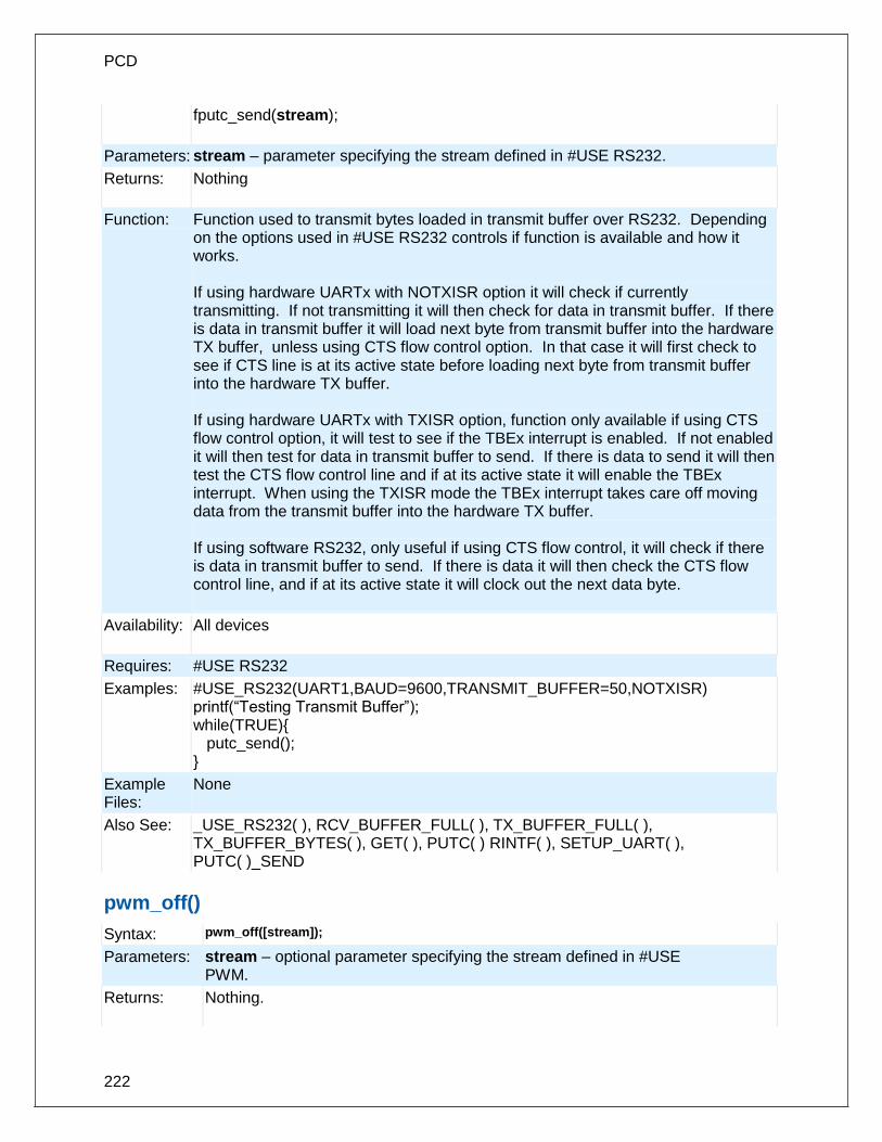
PCD
222
fputc_send(stream);
Parameters: stream – parameter specifying the stream defined in #USE RS232.
Returns: Nothing
Function: Function used to transmit bytes loaded in transmit buffer over RS232. Depending on the options used in #USE RS232 controls if function is available and how it works. If using hardware UARTx with NOTXISR option it will check if currently transmitting. If not transmitting it will then check for data in transmit buffer. If there is data in transmit buffer it will load next byte from transmit buffer into the hardware TX buffer, unless using CTS flow control option. In that case it will first check to see if CTS line is at its active state before loading next byte from transmit buffer into the hardware TX buffer. If using hardware UARTx with TXISR option, function only available if using CTS flow control option, it will test to see if the TBEx interrupt is enabled. If not enabled it will then test for data in transmit buffer to send. If there is data to send it will then test the CTS flow control line and if at its active state it will enable the TBEx interrupt. When using the TXISR mode the TBEx interrupt takes care off moving data from the transmit buffer into the hardware TX buffer. If using software RS232, only useful if using CTS flow control, it will check if there is data in transmit buffer to send. If there is data it will then check the CTS flow control line, and if at its active state it will clock out the next data byte.
Availability: All devices
Requires: #USE RS232
Examples: #USE_RS232(UART1,BAUD=9600,TRANSMIT_BUFFER=50,NOTXISR) printf(“Testing Transmit Buffer”); while(TRUE){ putc_send(); }
Example Files:
None
Also See: _USE_RS232( ), RCV_BUFFER_FULL( ), TX_BUFFER_FULL( ), TX_BUFFER_BYTES( ), GET( ), PUTC( ) RINTF( ), SETUP_UART( ), PUTC( )_SEND
pwm_off()
Syntax: pwm_off([stream]);
Parameters: stream – optional parameter specifying the stream defined in #USE PWM.
Returns: Nothing.

Built-in Functions
223
Function: To turn off the PWM signal.
Availability: All devices.
Requires: #USE PWM
Examples: #USE PWM(OUTPUT=PIN_C2, FREQUENCY=10kHz, DUTY=25) while(TRUE){ if(kbhit()){ c = getc(); if(c=='F') pwm_off(); } }
Example Files:
None
Also See: #use_pwm, pwm_on(), pwm_set_duty_percent(), pwm_set_duty(), pwm_set_frequency()
pwm_on()
Syntax: pwm_on([stream]);
Parameters: stream – optional parameter specifying the stream defined in #USE PWM.
Returns: Nothing.
Function: To turn on the PWM signal.
Availability: All devices.
Requires: #USE PWM
Examples: #USE PWM(OUTPUT=PIN_C2, FREQUENCY=10kHz, DUTY=25)
while(TRUE){
if(kbhit()){
c = getc();
if(c=='O')
pwm_on();
}
}
Example Files:
None
Also See: #use_pwm, pwm_off(), pwm_set_duty_percent(), pwm_set_duty, pwm_set_frequency()
pwm_set_duty()
Syntax: pwm_set_duty([stream],duty);
Parameters: stream – optional parameter specifying the stream defined in #USE

PCD
224
PWM. duty – an int16 constant or variable specifying the new PWM high time.
Returns: Nothing.
Function: To change the duty cycle of the PWM signal. The duty cycle percentage depends on the period of the PWM signal. This function is faster than pwm_set_duty_percent(), but requires you to know what the period of the PWM signal is.
Availability: All devices.
Requires: #USE PWM
Examples: #USE PWM(OUTPUT=PIN_C2, FREQUENCY=10kHz, DUTY=25)
Example Files:
None
Also See: #use_pwm, pwm_on, pwm_off(), pwm_set_frequency(), pwm_set_duty_percent()
pwm_set_duty_percent
Syntax: pwm_set_duty_percent([stream]), percent
Parameters: stream – optional parameter specifying the stream defined in #USE PWM. percent- an int16 constant or variable ranging from 0 to 1000 specifying the new PWM duty cycle, D is 0% and 1000 is 100.0%.
Returns: Nothing.
Function: To change the duty cycle of the PWM signal. Duty cycle percentage is based off the current frequency/period of the PWM signal.
Availability: All devices.
Requires: #USE PWM
Examples: #USE PWM(OUTPUT=PIN_C2, FREQUENCY=10kHz, DUTY=25)
pwm_set_duty_percent(500); //set PWM duty cycle to 50%
Example Files:
None
Also See: #use_pwm, pwm_on(), pwm_off(), pwm_set_frequency(), pwm_set_duty()
pwm_set_frequency
Syntax: pwm_set_frequency([stream],frequency);
Parameters: stream – optional parameter specifying the stream defined in #USE PWM. frequency – an int32 constant or variable specifying the new PWM frequency.

Built-in Functions
225
Returns: Nothing.
Function: To change the frequency of the PWM signal. Warning this may change the resolution of the PWM signal.
Availability: All devices.
Requires: #USE PWM
Examples: #USE PWM(OUTPUT=PIN_C2, FREQUENCY=10kHz, DUTY=25)
pwm_set_frequency(1000); //set PWM frequency to 1kHz
Example Files:
None
Also See: #use_pwm, pwm_on(), pwm_off(), pwm_set_duty_percent, pwm_set_duty()
qei_get_count( )
Syntax: value = qei_get_count( [type] );
Parameters: type - Optional parameter to specify which counter to get, defaults to position counter. Defined in devices .h file as: QEI_GET_POSITION_COUNT QEI_GET_VELOCITY_COUNT
Returns: The 16-bit value of the position counter or velocity counter.
Function: Reads the current 16-bit value of the position or velocity counter.
Availability: Devices that have the QEI module.
Requires: Nothing.
Examples: value = qei_get_counter(QEI_GET_POSITION_COUNT);
value = qei_get_counter();
value = qei_get_counter(QEI_GET_VELOCITY_COUNT);
Example Files:
None
Also See: setup_qei() , qei_set_count() , qei_status().
qei_set_count( )
Syntax: qei_set_count( value );
Parameters: value- The 16-bit value of the position counter.

PCD
226
Returns: void
Function: Write a 16-bit value to the position counter.
Availability: Devices that have the QEI module.
Requires: Nothing.
Examples: qei_set_counter(value);
Example Files: None
Also See: setup_qei() , qei_get_count() , qei_status().
qei_status( )
Syntax: status = qei_status( );
Parameters: None
Returns: The status of the QEI module.
Function: Returns the status of the QEI module.
Availability: Devices that have the QEI module.
Requires: Nothing.
Examples: status = qei_status();
Example Files: None
Also See: setup_qei() , qei_set_count() , qei_get_count().
qsort( )
Syntax: qsort (base, num, width, compare)
Parameters: base: Pointer to array of sort data num: Number of elements width: Width of elements compare: Function that compares two elements
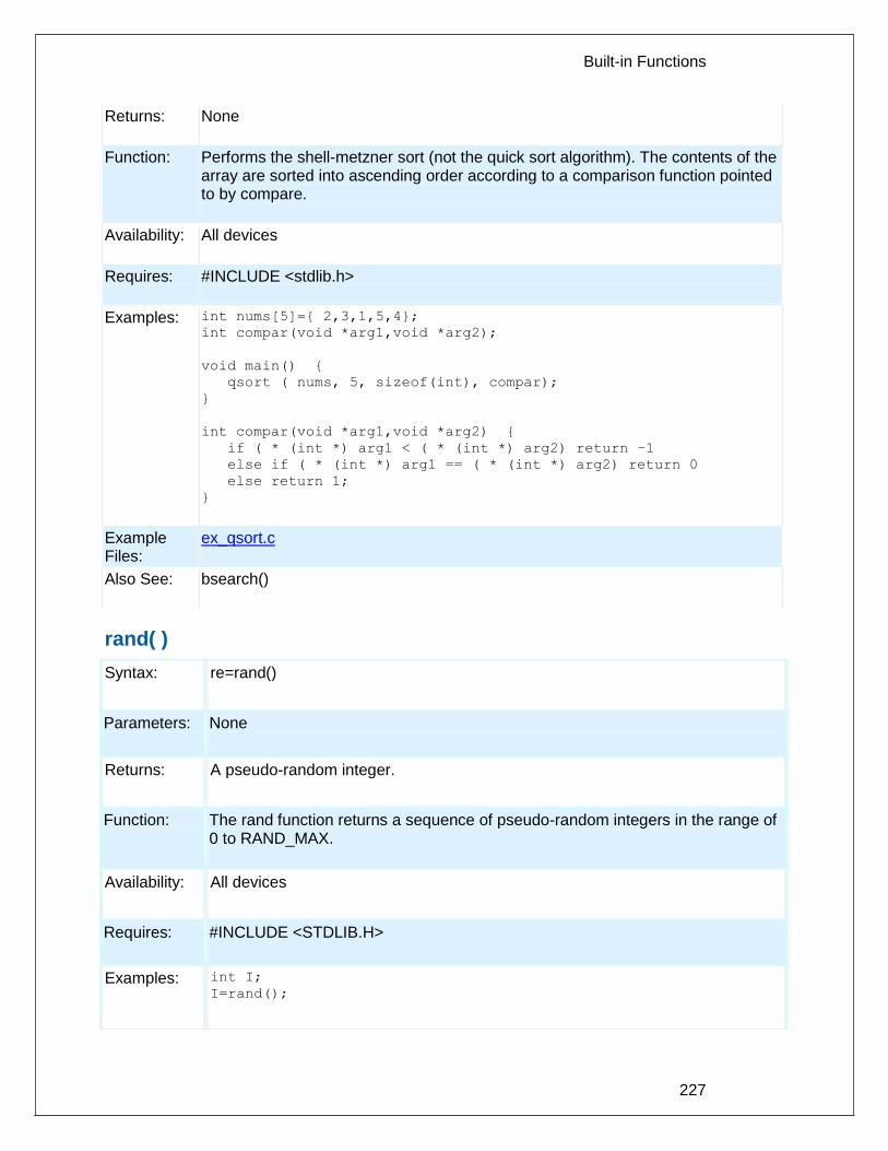
Built-in Functions
227
Returns: None
Function: Performs the shell-metzner sort (not the quick sort algorithm). The contents of the array are sorted into ascending order according to a comparison function pointed to by compare.
Availability: All devices
Requires: #INCLUDE <stdlib.h>
Examples: int nums[5]={ 2,3,1,5,4};
int compar(void *arg1,void *arg2);
void main() {
qsort ( nums, 5, sizeof(int), compar);
}
int compar(void *arg1,void *arg2) {
if ( * (int *) arg1 < ( * (int *) arg2) return –1
else if ( * (int *) arg1 == ( * (int *) arg2) return 0
else return 1;
}
Example Files:
ex_qsort.c
Also See: bsearch()
rand( )
Syntax: re=rand()
Parameters: None
Returns: A pseudo-random integer.
Function: The rand function returns a sequence of pseudo-random integers in the range of 0 to RAND_MAX.
Availability: All devices
Requires: #INCLUDE <STDLIB.H>
Examples: int I;
I=rand();

PCD
228
Example Files:
None
Also See: srand()
rcv_buffer_bytes( )
Syntax: value = rcv_buffer_bytes([stream]);
Parameters: stream – optional parameter specifying the stream defined in #USE RS232.
Returns: Number of bytes in receive buffer that still need to be retrieved.
Function: Function to determine the number of bytes in receive buffer that still need to be retrieved.
Availability: All devices
Requires: #USE RS232
Examples: #USE_RS232(UART1,BAUD=9600,RECEIVE_BUFFER=100) void main(void) { char c; if(rcv_buffer_bytes() > 10) c = getc(); }
Example Files:
None
Also See: _USE_RS232( ), RCV_BUFFER_FULL( ), TX_BUFFER_FULL( ), TX_BUFFER_BYTES( ), GETC( ), PUTC( ) ,PRINTF( ), SETUP_UART( ), PUTC_SEND( )
rcv_buffer_full( )
Syntax: value = rcv_buffer_full([stream]);
Parameters: stream – optional parameter specifying the stream defined in #USE RS232.
Returns: TRUE if receive buffer is full, FALSE otherwise.
Function: Function to test if the receive buffer is full.
Availability: All devices
Requires: #USE RS232
Examples: #USE_RS232(UART1,BAUD=9600,RECEIVE_BUFFER=100) void main(void) { char c; if(rcv_buffer_full())

Built-in Functions
229
c = getc(); }
Example Files:
None
Also See: _USE_RS232( ),RCV_BUFFER_BYTES( ), TX_BUFFER_BYTES( ) ,TX_BUFFER_FULL( ), GETC( ), PUTC( ), PRINTF( ), SETUP_UART( ), PUTC_SEND( )
read_adc( )
Syntax: value = read_adc ([mode])
Parameters: mode is an optional parameter. If used the values may be: ADC_START_AND_READ (continually takes readings, this is the default) ADC_START_ONLY (starts the conversion and returns) ADC_READ_ONLY (reads last conversion result)
Returns: Either a 8 or 16 bit int depending on #DEVICE ADC= directive.
Function: This function will read the digital value from the analog to digital converter. Calls to setup_adc(), setup_adc_ports() and set_adc_channel() should be made sometime before this function is called. The range of the return value depends on number of bits in the chips A/D converter and the setting in the #DEVICE ADC= directive as follows: #DEVICE 8 bit 10 bit 11 bit 12 bit 16 bit ADC=8 00-FF 00-FF 00-FF 00-FF 00-FF ADC=10 x 0-3FF x 0-3FF x ADC=11 x x 0-7FF x x
ADC=16 0FF00 0-FFC0
0-FFEO 0-FFF0 0-FFFF
Note: x is not defined
Availability: This function is only available on devices with A/D hardware.
Requires: Pin constants are defined in the devices .h file.
Examples: setup_adc( ADC_CLOCK_INTERNAL );
setup_adc_ports( ALL_ANALOG );
set_adc_channel(1);
while ( input(PIN_B0) ) {
delay_ms( 5000 );
value = read_adc();
printf("A/D value = %2x\n\r", value);
}
read_adc(ADC_START_ONLY);
sleep();
value=read_adc(ADC_READ_ONLY);

PCD
230
Example Files:
ex_admm.c, ex_14kad.c
Also See: setup_adc(), set_adc_channel(), setup_adc_ports(), #DEVICE, ADC Overview
read_bank( )
Syntax: value = read_bank (bank, offset)
Parameters: bank is the physical RAM bank 1-3 (depending on the device) offset is the offset into user RAM for that bank (starts at 0),
Returns: 8 bit int
Function: Read a data byte from the user RAM area of the specified memory bank. This function may be used on some devices where full RAM access by auto variables is not efficient. For example, setting the pointer size to 5 bits on the PIC16C57 chip will generate the most efficient ROM code. However, auto variables can not be above 1Fh. Instead of going to 8 bit pointers, you can save ROM by using this function to read from the hard-to-reach banks. In this case, the bank may be 1-3 and the offset may be 0-15.
Availability: All devices but only useful on PCB parts with memory over 1Fh and PCM parts with memory over FFh.
Requires: Nothing
Examples: // See write_bank() example to see
// how we got the data
// Moves data from buffer to LCD
i=0;
do {
c=read_bank(1,i++);
if(c!=0x13)
lcd_putc(c);
} while (c!=0x13);
Example Files:
ex_psp.c
Also See: write_bank(), and the "Common Questions and Answers" section for more information.

Built-in Functions
231
read_calibration( )
Syntax: value = read_calibration (n)
Parameters: n is an offset into calibration memory beginning at 0
Returns: An 8 bit byte
Function: The read_calibration function reads location "n" of the 14000-calibration memory.
Availability: This function is only available on the PIC14000.
Requires: Nothing
Examples: fin = read_calibration(16);
Example Files:
ex_14kad.c with 14kcal.c
Also See: None
read_configuration_memory( )
Syntax: read_configuration_memory(ramPtr, n)
Parameters: ramPtr is the destination pointer for the read results count is an 8 bit integer
Returns: undefined
Function: Reads n bytes of configuration memory and saves the values to ramPtr.
Availability: All
Requires: Nothing
Examples: int data[6];
read_configuration_memory(data,6);
Example Files:
None
Also See: write_configuration_memory(), read_program_memory(), Configuration Memory Overview,

PCD
232
read_eeprom( )
Syntax: value = read_eeprom (address )
Parameters: address is an 8 bit or 16 bit int depending on the part
Returns: An 8 bit int
Function: Reads a byte from the specified data EEPROM address. The address begins at 0 and the range depends on the part.
Availability: This command is only for parts with built-in EEPROMS
Requires: Nothing
Examples: #define LAST_VOLUME 10
volume = read_EEPROM (LAST_VOLUME);
Example Files:
None
Also See: write_eeprom(), Data Eeprom Overview
read_extended_ram( )
Syntax: read_extended_ram(page,address,data,count);
Parameters: page – the page in extended RAM to read from address – the address on the selected page to start reading from data – pointer to the variable to return the data to count – the number of bytes to read (0-32768)
Returns: Undefined
Function: To read data from the extended RAM of the PIC.
Availability: On devices with more then 30K of RAM.
Requires: Nothing
Examples: unsigned int8 data[8];
read_extended_ram(1,0x0000,data,8);
Example Files: None

Built-in Functions
233
Also See: read_extended_ram(), Extended RAM Overview
read_program_memory( )
read_external_memory( )
Syntax: READ_PROGRAM_MEMORY (address, dataptr, count ); READ_EXTERNAL_MEMORY (address, dataptr, count );
Parameters: address is 16 bits on PCM parts and 32 bits on PCH parts . The least significant bit should always be 0 in PCM. dataptr is a pointer to one or more bytes. count is a 8 bit integer on PIC16 and 16-bit for PIC18
Returns: undefined
Function: Reads count bytes from program memory at address to RAM at dataptr. B oth of these functions operate exactly the same.
Availability: Only devices that allow reads from program memory.
Requires: Nothing
Examples: char buffer[64];
read_external_memory(0x40000, buffer, 64);
Example Files:
None
Also See: write program memory( ), External memory overview , Program Eeprom Overview
read_high_speed_adc( )
Syntax: read_high_speed_adc(pair,mode,result); // Individual start and read or // read only read_high_speed_adc(pair,result); // Individual start and read read_high_speed_adc(pair); // Individual start only read_high_speed_adc(mode,result); // Global start and read or // read only read_high_speed_adc(result); // Global start and read read_high_speed_adc(); // Global start only
Parameters: pair – Optional parameter that determines which ADC pair number to start and/or read. Valid values are 0 to total number of ADC pairs. 0 starts and/or reads ADC pair AN0 and AN1, 1 starts and/or reads ADC pair AN2 and AN3, etc. If omitted then a global start and/or read will be performed.

PCD
234
mode – Optional parameter, if used the values may be:
· ADC_START_AND_READ (starts conversion and reads result)
· ADC_START_ONLY (starts conversion and returns)
· ADC_READ_ONLY(reads conversion result)
result – Pointer to return ADC conversion too. Parameter is optional, if not used the read_fast_adc() function can only perform a start.
Returns: Undefined
Function: This function is used to start an analog to digital conversion and/or read the digital value when the conversion is complete. Calls to setup_high_speed_adc() and setup_high_speed_adc_pairs() should be made sometime before this function is called. When using this function to perform an individual start and read or individual start only, the function assumes that the pair's trigger source was set to INDIVIDUAL_SOFTWARE_TRIGGER. When using this function to perform a global start and read, global start only, or global read only. The function will perform the following steps:
1. Determine which ADC pairs are set for GLOBAL_SOFTWARE_TRIGGER. 2. Clear the corresponding ready flags (if doing a start). 3. Set the global software trigger (if doing a start). 4. Read the corresponding ADC pairs in order from lowest to highest (if doing a read). 5. Clear the corresponding ready flags (if doing a read).
When using this function to perform a individual read only. The function can read the ADC result from any trigger source.
Availability: Only on dsPIC33FJxxGSxxx devices.
Requires: Constants are define in the device .h file.
Examples: //Individual start and read
int16 result[2];
setup_high_speed_adc(ADC_CLOCK_DIV_4);
setup_high_speed_adc_pair(0, INDIVIDUAL_SOFTWARE_TRIGGER);
read_high_speed_adc(0, result); //starts conversion for AN0 and AN1
and stores
//result in result[0] and result[1]
//Global start and read
int16 result[4];
setup_high_speed_adc(ADC_CLOCK_DIV_4);

Built-in Functions
235
setup_high_speed_adc_pair(0, GLOBAL_SOFTWARE_TRIGGER);
setup_high_speed_adc_pair(4, GLOBAL_SOFTWARE_TRIGGER);
read_high_speed_adc(result); //starts conversion for AN0, AN1,
//AN8 and AN9 and
//stores result in result[0], result
//[1], result[2]
and result[3]
Example Files:
None
Also See: setup_high_speed_adc(), setup_high_speed_adc_pair(), high_speed_adc_done()
read_program_eeprom( )
Syntax: value = read_program_eeprom (address)
Parameters: address is 16 bits on PCM parts and 32 bits on PCH parts
Returns: 16 bits
Function: Reads data from the program memory.
Availability: Only devices that allow reads from program memory.
Requires: Nothing
Examples: checksum = 0;
for(i=0;i<8196;i++)
checksum^=read_program_eeprom(i);
printf("Checksum is %2X\r\n",checksum);
Example Files:
None
Also See: write_program_eeprom(), write_eeprom(), read_eeprom(), Program Eeprom Overview
realloc( )
Syntax: realloc (ptr, size)
Parameters: ptr is a null pointer or a pointer previously returned by calloc or malloc or realloc function, size is an integer representing the number of byes to be allocated.
Returns: A pointer to the possibly moved allocated memory, if any. Returns null otherwise.

PCD
236
Function: The realloc function changes the size of the object pointed to by the ptr to the size specified by the size. The contents of the object shall be unchanged up to the lesser of new and old sizes. If the new size is larger, the value of the newly allocated space is indeterminate. If ptr is a null pointer, the realloc function behaves like malloc function for the specified size. If the ptr does not match a pointer earlier returned by the calloc, malloc or realloc, or if the space has been deallocated by a call to free or realloc function, the behavior is undefined. If the space cannot be allocated, the object pointed to by ptr is unchanged. If size is zero and the ptr is not a null pointer, the object is to be freed.
Availability: All devices
Requires: #INCLUDE <stdlibm.h>
Examples: int * iptr;
iptr=malloc(10);
realloc(iptr,20)
// iptr will point to a block of memory of 20 bytes, if available.
Example Files:
None
Also See: malloc(), free(), calloc()
release_io()
Syntax: release_io();
Parameters: none
Returns: nothing
Function: The function releases the I/O pins after the device wakes up from deep sleep, allowing the state of the I/O pins to change
Availability: Devices with a deep sleep module.
Requires: Nothing
Examples: unsigned int16 restart;
restart = restart_cause();
if(restart == RTC_FROM_DS)
release_io();
Example None

Built-in Functions
237
Files:
Also See: sleep()
reset_cpu( )
Syntax: reset_cpu()
Parameters: None
Returns: This function never returns
Function: This is a general purpose device reset. It will jump to location 0 on PCB and PCM parts and also reset the registers to power-up state on the PIC18XXX.
Availability: All devices
Requires: Nothing
Examples: if(checksum!=0)
reset_cpu();
Example Files:
None
Also See: None
restart_cause( )
Syntax: value = restart_cause()
Parameters: None
Returns: A value indicating the cause of the last processor reset. The actual values are device dependent. See the device .h file for specific values for a specific device. Some example values are: WDT_FROM_SLEEP, WDT_TIMEOUT, MCLR_FROM_SLEEP and NORMAL_POWER_UP.
Function: Returns the cause of the last processor reset.
Availability: All devices
Requires: Constants are defined in the devices .h file.
Examples: switch ( restart_cause() ) {
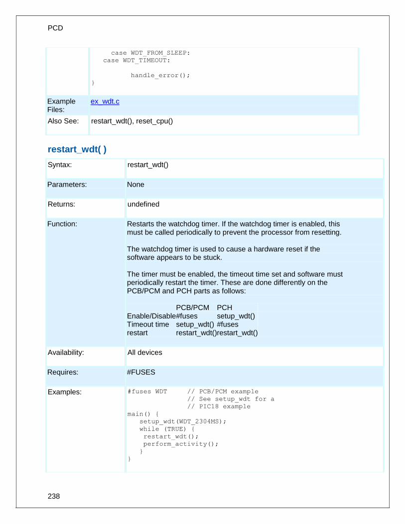
PCD
238
case WDT_FROM_SLEEP:
case WDT_TIMEOUT:
handle_error();
}
Example Files:
ex_wdt.c
Also See: restart_wdt(), reset_cpu()
restart_wdt( )
Syntax: restart_wdt()
Parameters: None
Returns: undefined
Function: Restarts the watchdog timer. If the watchdog timer is enabled, this must be called periodically to prevent the processor from resetting. The watchdog timer is used to cause a hardware reset if the software appears to be stuck. The timer must be enabled, the timeout time set and software must periodically restart the timer. These are done differently on the PCB/PCM and PCH parts as follows: PCB/PCM PCH Enable/Disable #fuses setup_wdt() Timeout time setup_wdt() #fuses restart restart_wdt() restart_wdt()
Availability: All devices
Requires: #FUSES
Examples: #fuses WDT // PCB/PCM example
// See setup_wdt for a
// PIC18 example
main() {
setup_wdt(WDT_2304MS);
while (TRUE) {
restart_wdt();
perform_activity();
}
}

Built-in Functions
239
Example Files:
ex_wdt.c
Also See: #FUSES, setup_wdt(), WDT or Watch Dog Timer Overview
rotate_left( )
Syntax: rotate_left (address, bytes)
Parameters: address is a pointer to memory bytes is a count of the number of bytes to work with.
Returns: undefined
Function:
Rotates a bit through an array or structure. The address may be an array identifier or an address to a byte or structure (such as &data). Bit 0 of the lowest BYTE in RAM is considered the LSB.
Availability: All devices
Requires: Nothing
Examples:
x = 0x86;
rotate_left( &x, 1);
// x is now 0x0d
Example Files:
None
Also See: rotate_right(), shift_left(), shift_right()
rotate_right( )
Syntax: rotate_right (address, bytes)
Parameters: address is a pointer to memory, bytes is a count of the number of bytes to work with.
Returns: undefined
Function: Rotates a bit through an array or structure. The address may be an array identifier or an address to a byte or structure (such as &data). Bit 0 of the lowest BYTE in RAM is considered the LSB.
Availability: All devices

PCD
240
Requires: Nothing
Examples: struct {
int cell_1 : 4;
int cell_2 : 4;
int cell_3 : 4;
int cell_4 : 4; } cells;
rotate_right( &cells, 2);
rotate_right( &cells, 2);
rotate_right( &cells, 2);
rotate_right( &cells, 2);
// cell_1->4, 2->1, 3->2 and 4-> 3
Example Files:
None
Also See: rotate_left(), shift_left(), shift_right()
rtc_alarm_read( )
Syntax: rtc_alarm_read(&datetime);
Parameters: datetime- A structure that will contain the values to be written to the alarm in the RTCC module. Structure used in read and write functions are defined in the device header file as rtc_time_t
Returns: void
Function: Reads the date and time from the alarm in the RTCC module to structure datetime.
Availability: Devices that have the RTCC module.
Requires: Nothing.
Examples: rtc_alarm_read(&datetime);
Example Files:
None
Also See: rtc_read(), rtc_alarm_read(), rtc_alarm_write(), setup_rtc_alarm(), rtc_write(), setup_rtc()
rtc_alarm_write( )
Syntax: rtc_alarm_write(&datetime);

Built-in Functions
241
Parameters: datetime- A structure that will contain the values to be written to the alarm in the RTCC module. Structure used in read and write functions are defined in the device header file as rtc_time_t.
Returns: void
Function: Writes the date and time to the alarm in the RTCC module as specified in the structure date time.
Availability: Devices that have the RTCC module.
Requires: Nothing.
Examples: rtc_alarm_write(&datetime);
Example Files:
None
Also See: rtc_read(), rtc_alarm_read(), rtc_alarm_write(), setup_rtc_alarm(), rtc_write(), setup_rtc()
rtc_read( )
Syntax: rtc_read(&datetime);
Parameters: datetime- A structure that will contain the values returned by the RTCC module. Structure used in read and write functions are defined in the device header file as rtc_time_t.
Returns: void
Function: Reads the current value of Time and Date from the RTCC module and stores the structure date time.
Availability: Devices that have the RTCC module.
Requires: Nothing.
Examples: rtc_read(&datetime);
Example Files:
ex_rtcc.c

PCD
242
Also See: rtc_read(), rtc_alarm_read(), rtc_alarm_write(), setup_rtc_alarm(), rtc_write(), setup_rtc()
rtc_write( )
Syntax: rtc_write(&datetime);
Parameters: datetime- A structure that will contain the values to be written to the RTCC module. Structure used in read and write functions are defined in the device header file as rtc_time_t.
Returns: void
Function: Writes the date and time to the RTCC module as specified in the structure date time.
Availability: Devices that have the RTCC module.
Requires: Nothing.
Examples: rtc_write(&datetime);
Example Files:
ex_rtcc.c
Also See: rtc_read() , rtc_alarm_read() , rtc_alarm_write() , setup_rtc_alarm() , rtc_write(), setup_rtc()
rtos_await( )
The RTOS is only included in the PCW, PCWH and PCWHD software packages.
Syntax: rtos_await (expre)
Parameters: expre is a logical expression.
Returns: None
Function: This function can only be used in an RTOS task. This function waits for expre to be true before continuing execution of the rest of the code of the RTOS task. This function allows other tasks to execute while the task waits for expre to be true.
Availability: All devices
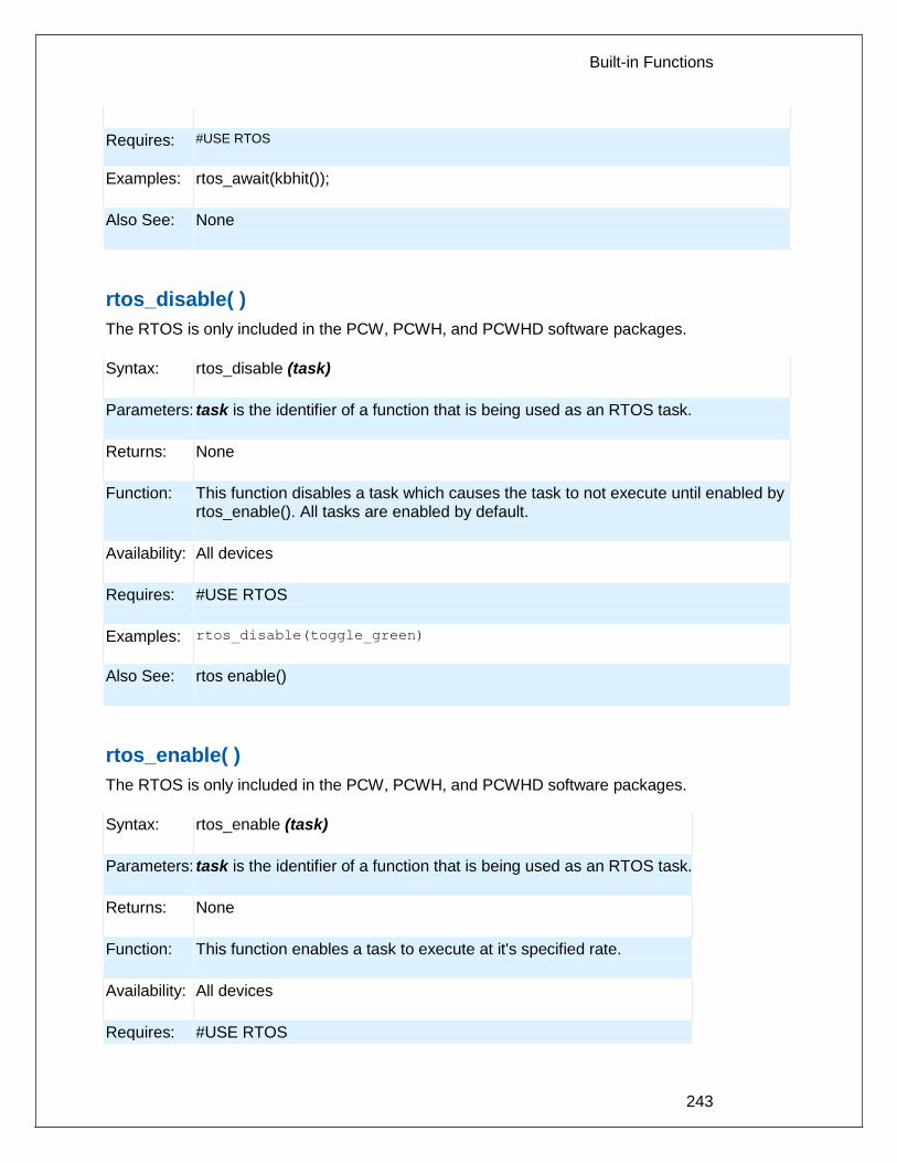
Built-in Functions
243
Requires: #USE RTOS
Examples: rtos_await(kbhit());
Also See: None
rtos_disable( )
The RTOS is only included in the PCW, PCWH, and PCWHD software packages.
Syntax: rtos_disable (task)
Parameters: task is the identifier of a function that is being used as an RTOS task.
Returns: None
Function: This function disables a task which causes the task to not execute until enabled by rtos_enable(). All tasks are enabled by default.
Availability: All devices
Requires: #USE RTOS
Examples: rtos_disable(toggle_green)
Also See: rtos enable()
rtos_enable( )
The RTOS is only included in the PCW, PCWH, and PCWHD software packages.
Syntax: rtos_enable (task)
Parameters: task is the identifier of a function that is being used as an RTOS task.
Returns: None
Function: This function enables a task to execute at it's specified rate.
Availability: All devices
Requires: #USE RTOS

PCD
244
Examples: rtos_enable(toggle_green);
Also See: rtos disable()
rtos_msg_poll( )
The RTOS is only included in the PCW, PCWH and PCWHD software packages.
Syntax: i = rtos_msg_poll()
Parameters: None
Returns: An integer that specifies how many messages are in the queue.
Function: This function can only be used inside an RTOS task. This function returns the number of messages that are in the queue for the task that the rtos_msg_poll() function is used in.
Availability: All devices
Requires: #USE RTOS
Examples: if(rtos_msg_poll())
Also See: rtos msg send(), rtos msg read()
rtos_msg_read( )
The RTOS is only included in the PCW, PCWH and PCWHD software packages.
Syntax: b = rtos_msg_read()
Parameters: None
Returns: A byte that is a message for the task.
Function: This function can only be used inside an RTOS task. This function reads in the next (message) of the queue for the task that the rtos_msg_read() function is used in.
Availability: All devices
Requires: #USE RTOS

Built-in Functions
245
Examples: if(rtos_msg_poll()) {
b = rtos_msg_read();
Also See: rtos msg poll(), rtos msg send()
rtos_msg_send( )
The RTOS is only included in the PCW, PCWH and PCWHD software packages.
Syntax: rtos_msg_send(task, byte)
Parameters: task is the identifier of a function that is being used as an RTOS task byte is the byte to send to task as a message.
Returns: None
Function: This function can be used anytime after rtos_run() has been called. This function sends a byte long message (byte) to the task identified by task.
Availability: All devices
Requires: #USE RTOS
Examples: if(kbhit())
{
rtos_msg_send(echo, getc());
}
Also See: rtos_msg_poll(), rtos_msg_read()
rtos_overrun( )
The RTOS is only included in the PCW, PCWH and PCWHD software packages.
Syntax: rtos_overrun([task])
Parameters: task is an optional parameter that is the identifier of a function that is being used as an RTOS task
Returns: A 0 (FALSE) or 1 (TRUE)
Function: This function returns TRUE if the specified task took more time to execute than it was allocated. If no task was specified, then it returns TRUE if any task ran over it's alloted execution time.

PCD
246
Availability: All devices
Requires: #USE RTOS(statistics)
Examples: rtos_overrun()
Also See: None
rtos_run( )
The RTOS is only included in the PCW, PCWH, and PCWHD software packages.
Syntax: rtos_run()
Parameters: None
Returns: None
Function: This function begins the execution of all enabled RTOS tasks. This function controls the execution of the RTOS tasks at the allocated rate for each task. This function will return only when rtos_terminate() is called.
Availability: All devices
Requires: #USE RTOS
Examples: rtos_run()
Also See: rtos terminate()
rtos_signal( )
The RTOS is only included in the PCW, PCWH and PCWHD software packages.
Syntax: rtos_signal (sem)
Parameters: sem is a global variable that represents the current availability of a shared system resource (a semaphore).
Returns: None
Function: This function can only be used by an RTOS task. This function increments sem to let waiting tasks know that a shared resource is available for use.
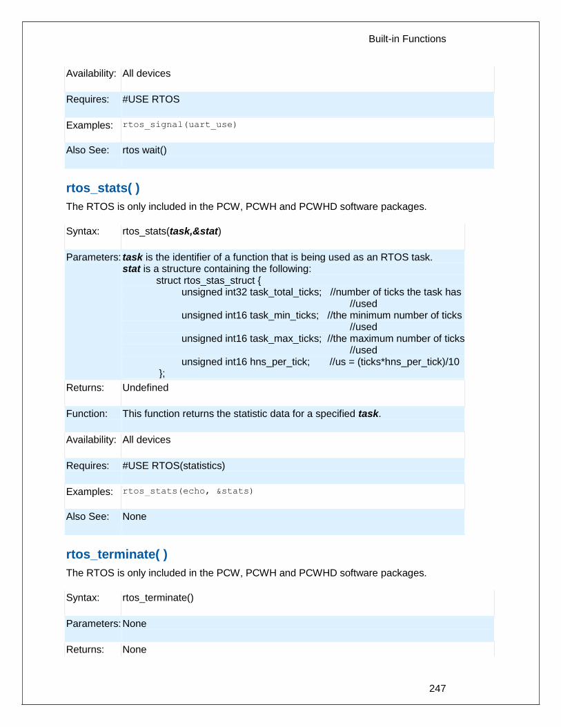
Built-in Functions
247
Availability: All devices
Requires: #USE RTOS
Examples: rtos_signal(uart_use)
Also See: rtos wait()
rtos_stats( )
The RTOS is only included in the PCW, PCWH and PCWHD software packages.
Syntax: rtos_stats(task,&stat)
Parameters: task is the identifier of a function that is being used as an RTOS task. stat is a structure containing the following: struct rtos_stas_struct { unsigned int32 task_total_ticks; //number of ticks the task has //used unsigned int16 task_min_ticks; //the minimum number of ticks //used unsigned int16 task_max_ticks; //the maximum number of ticks //used unsigned int16 hns_per_tick; //us = (ticks*hns_per_tick)/10 };
Returns: Undefined
Function: This function returns the statistic data for a specified task.
Availability: All devices
Requires: #USE RTOS(statistics)
Examples: rtos_stats(echo, &stats)
Also See: None
rtos_terminate( )
The RTOS is only included in the PCW, PCWH and PCWHD software packages.
Syntax: rtos_terminate()
Parameters: None
Returns: None

PCD
248
Function: This function ends the execution of all RTOS tasks. The execution of the program will continue with the first line of code after the rtos_run() call in the program. (This function causes rtos_run() to return.)
Availability: All devices
Requires: #USE RTOS
Examples: rtos_terminate()
Also See: rtos run()
rtos_wait( )
The RTOS is only included in the PCW, PCWH and PCWHD software packages.
Syntax: rtos_wait (sem)
Parameters: sem is a global variable that represents the current availability of a shared system resource (a semaphore).
Returns: None
Function: This function can only be used by an RTOS task. This function waits for sem to be greater than 0 (shared resource is available), then decrements sem to claim usage of the shared resource and continues the execution of the rest of the code the RTOS task. This function allows other tasks to execute while the task waits for the shared resource to be available.
Availability: All devices
Requires: #USE RTOS
Examples: rtos_wait(uart_use)
Also See: rtos signal()
rtos_yield( )
The RTOS is only included in the PCW, PCWH and PCWHD software packages.
Syntax: rtos_yield()
Parameters: None

Built-in Functions
249
Returns: None
Function: This function can only be used in an RTOS task. This function stops the execution of the current task and returns control of the processor to rtos_run(). When the next task executes, it will start it's execution on the line of code after the rtos_yield().
Availability: All devices
Requires: #USE RTOS
Examples: void yield(void)
{
printf(“Yielding...\r\n”);
rtos_yield();
printf(“Executing code after yield\r\n”);
}
Also See: None
set_adc_channel( )
Syntax: set_adc_channel (chan [,neg]))
Parameters: chan is the channel number to select. Channel numbers start at 0 and are labeled in the data sheet AN0, AN1. For devices with a differential ADC it sets the positive channel to use. neg is optional and is used for devices with a differential ADC only. It sets the negative channel to use, channel numbers can be 0 to 6 or VSS. If no parameter is used the negative channel will be set to VSS by default.
Returns: undefined
Function: Specifies the channel to use for the next read_adc() call. Be aware that you must wait a short time after changing the channel before you can get a valid read. The time varies depending on the impedance of the input source. In general 10us is good for most applications. You need not change the channel before every read if the channel does not change.
Availability: This function is only available on devices with A/D hardware.
Requires: Nothing
Examples: set_adc_channel(2);
delay_us(10);
value = read_adc();

PCD
250
Example Files:
ex_admm.c
Also See: read_adc(), setup_adc(), setup_adc_ports(), ADC Overview
set_nco_inc_value( )
Syntax: set_nco_inc_value(value);
Parameters: value- 16-bit value to set the NCO increment registers to (0 - 65535)
Returns: Undefined
Function: Sets the value that the NCO's accumulator will be incremented by on each clock pulse. The increment registers are double buffered so the new value won't be applied until the accumulator rolls-over.
Availability: On devices with a NCO module.
Examples: set_nco_inc_value(inc_value); //sets the new
increment value
Example Files:
None
Also See: setup_nco( ), get_nco_accumulator( ), get_nco_inc_value( )
Syntax: set_open_drain_a(value) set_open_drain_b(value) set_open_drain_c(value) set_open_drain_d(value) set_open_drain_e(value) set_open_drain_f(value) set_open_drain_g(value) set_open_drain_h(value) set_open_drain_j(value) set_open_drain_k(value)
Parameters: value – is a bitmap corresponding to the pins of the port. Setting a bit causes the corresponding pin to act as an open-drain output.
Returns: Nothing
Function Enables/Disables open-drain output capability on port pins. Not all ports or port pins have open-drain capability, refer to devices datasheet for port and pin availability.
Availability On device that have open-drain capability.

Built-in Functions
251
Examples: set_open_drain_b(0x0001); //enables open-drain output on PIN_B0, disable on all //other port B pins.
Example Files:
None.
set_power_pwm_override( )
Syntax: set_power_pwm_override(pwm, override, value)
Parameters: pwm is a constant between 0 and 7 Override is true or false Value is 0 or 1
Returns: undefined
Function: pwm selects which module will be affected. Override determines whether the output is to be determined by the OVDCONS register or the PDC registers. When override is false, the PDC registers determine the output. When override is true, the output is determined by the value stored in OVDCONS. value determines if pin is driven to it's active staet or if pin will be inactive. I will be driven to its active state, 0 pin will be inactive.
Availability: All devices equipped with PWM.
Requires: None
Examples: set_power_pwm_override(1, true, 1); //PWM1 will be
//overridden to active
//state
set_power_pwm_override(1, false, 0); //PMW1 will not be
//overidden
Example Files:
None
Also See: setup_power_pwm(), setup_power_pwm_pins(), set_power_pwmX_duty()
set_power_pwmx_duty( )
Syntax: set_power_pwmX_duty(duty)
Parameters: X is 0, 2, 4, or 6 Duty is an integer between 0 and 16383.
Returns: undefined
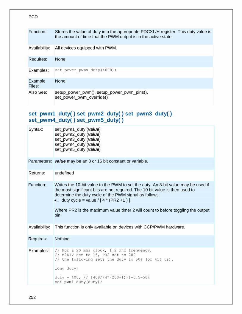
PCD
252
Function: Stores the value of duty into the appropriate PDCXL/H register. This duty value is the amount of time that the PWM output is in the active state.
Availability: All devices equipped with PWM.
Requires: None
Examples: set_power_pwmx_duty(4000);
Example Files:
None
Also See: setup_power_pwm(), setup_power_pwm_pins(), set_power_pwm_override()
set_pwm1_duty( ) set_pwm2_duty( ) set_pwm3_duty( ) set_pwm4_duty( ) set_pwm5_duty( )
Syntax: set_pwm1_duty (value) set_pwm2_duty (value) set_pwm3_duty (value) set_pwm4_duty (value) set_pwm5_duty (value)
Parameters: value may be an 8 or 16 bit constant or variable.
Returns: undefined
Function: Writes the 10-bit value to the PWM to set the duty. An 8-bit value may be used if the most significant bits are not required. The 10 bit value is then used to determine the duty cycle of the PWM signal as follows:
duty cycle = value / [ 4 * (PR2 +1 ) ] Where PR2 is the maximum value timer 2 will count to before toggling the output pin.
Availability: This function is only available on devices with CCP/PWM hardware.
Requires: Nothing
Examples: // For a 20 mhz clock, 1.2 khz frequency,
// t2DIV set to 16, PR2 set to 200
// the following sets the duty to 50% (or 416 us).
long duty;
duty = 408; // [408/(4*(200+1))]=0.5=50%
set_pwm1_duty(duty);

Built-in Functions
253
Example Files:
ex_pwm.c
Also See: setup_ccpX(), CCP1 Overview
set_ticks( )
Syntax: set_ticks([stream],value);
Parameters: stream – optional parameter specifying the stream defined in #USE TIMER value – a 8, 16 or 32 bit integer, specifying the new value of the tick timer. (int8, int16 or int32)
Returns: void
Function: Sets the new value of the tick timer. Size passed depends on the size of the tick timer.
Availability: All devices.
Requires: #USE TIMER(options)
Examples: #USE TIMER(TIMER=1,TICK=1ms,BITS=16,NOISR)
void main(void) {
unsigned int16 value = 0x1000;
set_ticks(value);
}
Example Files:
None
Also See: #USE TIMER, get_ticks()
set_timerA( )
Syntax: set_timerA(value);
Parameters: An 8 bit integer. Specifying the new value of the timer. (int8)
Returns: undefined
Function: Sets the current value of the timer. All timers count up. When a timer reaches the maximum value it will flip over to 0 and continue counting (254, 255, 0, 1, 2, …).

PCD
254
Availability: This function is only available on devices with Timer A hardware.
Requires: Nothing
Examples: // 20 mhz clock, no prescaler, set timer A
// to overflow in 35us
set_timerA(81); // 256-(.000035/(4/20000000))
Example Files:
none
Also See: get_timerA( ), setup_timer_A( ), TimerA Overview
set_timerB( )
Syntax: set_timerB(value);
Parameters: An 8 bit integer. Specifying the new value of the timer. (int8)
Returns: undefined
Function: Sets the current value of the timer. All timers count up. When a timer reaches the maximum value it will flip over to 0 and continue counting (254, 255, 0, 1, 2, …).
Availability: This function is only available on devices with Timer B hardware.
Requires: Nothing
Examples: // 20 mhz clock, no prescaler, set timer B
// to overflow in 35us
set_timerB(81); // 256-(.000035/(4/20000000))
Example Files:
none
Also See: get_timerB( ), setup_timer_B( ), TimerB Overview
set_timerx( )
Syntax: set_timerX(value)
Parameters: A 16 bit integer, specifiying the new value of the timer. (int16)
Returns: void
Function: Allows the user to set the value of the timer.

Built-in Functions
255
Availability: This function is available on all devices that have a valid timerX.
Requires: Nothing
Examples: if(EventOccured())
set_timer2(0);//reset the timer.
Example Files:
None
Returns: undefined
set_tris_x( )
Syntax: set_tris_a (value) set_tris_b (value) set_tris_c (value) set_tris_d (value) set_tris_e (value) set_tris_f (value) set_tris_g (value) set_tris_h (value) set_tris_j (value) set_tris_k (value)
Parameters: value is an 8 bit int with each bit representing a bit of the I/O port.
Returns: undefined
Function: These functions allow the I/O port direction (TRI-State) registers to be set. This must be used with FAST_IO and when I/O ports are accessed as memory such as when a # BYTE directive is used to access an I/O port. Using the default standard I/O the built in functions set the I/O direction automatically. Each bit in the value represents one pin. A 1 indicates the pin is input and a 0 indicates it is output.
Availability: All devices (however not all devices have all I/O ports)
Requires: Nothing
Examples: SET_TRIS_B( 0x0F );
// B7,B6,B5,B4 are outputs
// B3,B2,B1,B0 are inputs
Example Files:
lcd.c
Also See: #USE FAST_IO, #USE FIXED_IO, #USE STANDARD_IO, General Purpose I/O

PCD
256
Parameters: value is an 8 bit int with each bit representing a bit of the I/O port.
Returns: undefined
Function: These functions allow the I/O port direction (TRI-State) registers to be set. This must be used with FAST_IO and when I/O ports are accessed as memory such as when a # BYTE directive is used to access an I/O port. Using the default standard I/O the built in functions set the I/O direction automatically. Each bit in the value represents one pin. A 1 indicates the pin is input and a 0 indicates it is output.
Availability: All devices (however not all devices have all I/O ports)
Requires: Nothing
Examples: SET_TRIS_B( 0x0F );
// B7,B6,B5,B4 are outputs
// B3,B2,B1,B0 are inputs
Example Files:
lcd.c
Also See: #USE FAST_IO, #USE FIXED_IO, #USE STANDARD_IO, General Purpose I/O
Example Files:
lcd.c
Also See: #USE FAST_IO, #USE FIXED_IO, #USE STANDARD_IO, General Purpose I/O
set_uart_speed( )
Syntax: set_uart_speed (baud, [stream, clock])
Parameters: baud is a constant representing the number of bits per second. stream is an optional stream identifier. clock is an optional parameter to indicate what the current clock is if it is different from the #use delay value
Returns: undefined
Function: Changes the baud rate of the built-in hardware RS232 serial port at run-time.

Built-in Functions
257
Availability: This function is only available on devices with a built in UART.
Requires: #USE RS232
Examples: // Set baud rate based on setting
// of pins B0 and B1
switch( input_b() & 3 ) {
case 0 : set_uart_speed(2400); break;
case 1 : set_uart_speed(4800); break;
case 2 : set_uart_speed(9600); break;
case 3 : set_uart_speed(19200); break;
}
Example Files:
loader.c
Also See: #USE RS232, putc(), getc(), setup uart(), RS232 I/O Overview,
setjmp( )
Syntax: result = setjmp (env)
Parameters: env: The data object that will receive the current environment
Returns: If the return is from a direct invocation, this function returns 0. If the return is from a call to the longjmp function, the setjmp function returns a nonzero value and it's the same value passed to the longjmp function.
Function: Stores information on the current calling context in a data object of type jmp_buf and which marks where you want control to pass on a corresponding longjmp call.
Availability: All devices
Requires: #INCLUDE <setjmp.h>
Examples: result = setjmp(jmpbuf);
Example Files:
None
Also See: longjmp()
setup_adc(mode)
Syntax: setup_adc (mode); setup_adc2(mode);

PCD
258
Parameters:
mode- Analog to digital mode. The valid options vary depending on the device. See the devices .h file for all options. Some typical options include:
ADC_OFF
ADC_CLOCK_INTERNAL
ADC_CLOCK_DIV_32
Returns: undefined
Function: Configures the analog to digital converter.
Availability: Only the devices with built in analog to digital converter.
Requires: Constants are defined in the devices .h file.
Examples:
setup_adc_ports( ALL_ANALOG );
setup_adc(ADC_CLOCK_INTERNAL );
set_adc_channel( 0 );
value = read_adc();
setup_adc( ADC_OFF );
Example Files:
ex_admm.c
Also See:
setup_adc_ports(), set_adc_channel(), read_adc(), #DEVICE, ADC Overview, see header file for device selected
setup_adc_ports( )
Syntax: setup_adc_ports (value) setup_adc_ports (ports, [reference])
Parameters: value - a constant defined in the devices .h file ports - is a constant specifying the ADC pins to use reference - is an optional constant specifying the ADC reference to use By default, the reference voltage are Vss and Vdd
Returns: undefined
Function: Sets up the ADC pins to be analog, digital, or a combination and the voltage reference to use when computing the ADC value. The allowed analog pin combinations vary depending on the chip and are defined by using the bitwise OR to concatenate selected pins together. Check the device include file for a complete

Built-in Functions
259
list of available pins and reference voltage settings. The constants ALL_ANALOG and NO_ANALOGS are valid for all chips. Some other example pin definitions are:
Also See: setup_adc(), read_adc(), set_adc_channel(), ADC Overview
setup_ccp1( ) setup_ccp2( ) setup_ccp3( ) setup_ccp4( ) setup_ccp5( ) setup_ccp6( )
Syntax: setup_ccp1 (mode) or setup_ccp1 (mode, pwm) setup_ccp2 (mode) or setup_ccp2 (mode, pwm) setup_ccp3 (mode) or setup_ccp3 (mode, pwm) setup_ccp5 (mode) or setup_ccp5 (mode, pwm) setup_ccp6 (mode) or setup_ccp6 (mode, pwm)
Parameters: mode is a constant. Valid constants are defined in the devices .h file and refer to devices .h file for all options, some options are as follows: Disable the CCP: CCP_OFF Set CCP to capture mode:
CCP_CAPTURE_FE Capture on falling edge
CCP_CAPTURE_RE Capture on rising edge
CCP_CAPTURE_DIV_4 Capture after 4 pulses
CCP_CAPTURE_DIV_16 Capture after 16 pulses
Set CCP to compare mode:
CCP_COMPARE_SET_ON_MATCH Output high on compare
CCP_COMPARE_CLR_ON_MATCH Output low on compare
CCP_COMPARE_INT interrupt on compare
CCP_COMPARE_RESET_TIMER Reset timer on compare
Set CCP to PWM mode:
CCP_PWM Enable Pulse Width Modulator
Constants used for ECCP modules are as follows:
CCP_PWM_H_H
CCP_PWM_H_L
CCP_PWM_L_H
CCP_PWM_L_L
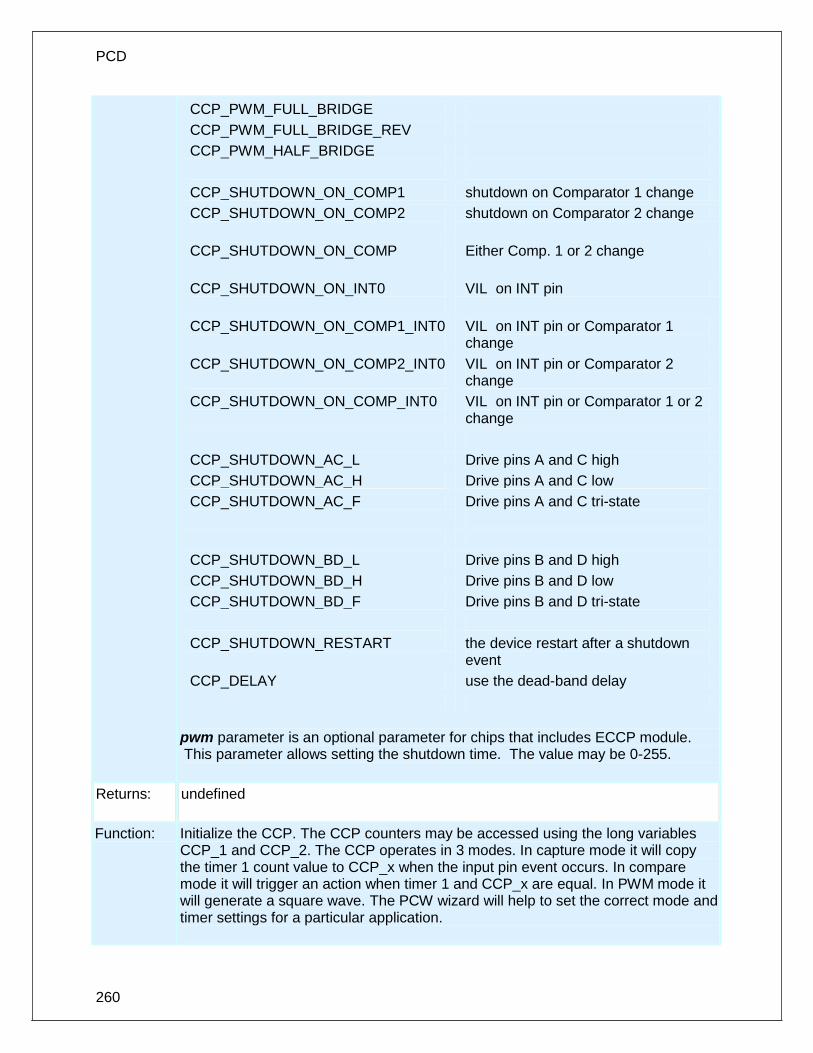
PCD
260
CCP_PWM_FULL_BRIDGE
CCP_PWM_FULL_BRIDGE_REV
CCP_PWM_HALF_BRIDGE
CCP_SHUTDOWN_ON_COMP1 shutdown on Comparator 1 change
CCP_SHUTDOWN_ON_COMP2
shutdown on Comparator 2 change
CCP_SHUTDOWN_ON_COMP
Either Comp. 1 or 2 change
CCP_SHUTDOWN_ON_INT0
VIL on INT pin
CCP_SHUTDOWN_ON_COMP1_INT0
VIL on INT pin or Comparator 1 change
CCP_SHUTDOWN_ON_COMP2_INT0
VIL on INT pin or Comparator 2 change
CCP_SHUTDOWN_ON_COMP_INT0
VIL on INT pin or Comparator 1 or 2 change
CCP_SHUTDOWN_AC_L Drive pins A and C high
CCP_SHUTDOWN_AC_H Drive pins A and C low
CCP_SHUTDOWN_AC_F Drive pins A and C tri-state
CCP_SHUTDOWN_BD_L Drive pins B and D high
CCP_SHUTDOWN_BD_H Drive pins B and D low
CCP_SHUTDOWN_BD_F Drive pins B and D tri-state
CCP_SHUTDOWN_RESTART the device restart after a shutdown event
CCP_DELAY use the dead-band delay
pwm parameter is an optional parameter for chips that includes ECCP module. This parameter allows setting the shutdown time. The value may be 0-255.
Returns: undefined
Function: Initialize the CCP. The CCP counters may be accessed using the long variables CCP_1 and CCP_2. The CCP operates in 3 modes. In capture mode it will copy the timer 1 count value to CCP_x when the input pin event occurs. In compare mode it will trigger an action when timer 1 and CCP_x are equal. In PWM mode it will generate a square wave. The PCW wizard will help to set the correct mode and timer settings for a particular application.

Built-in Functions
261
Availability: This function is only available on devices with CCP hardware.
Requires: Constants are defined in the devices .h file.
Examples: setup_ccp1(CCP_CAPTURE_RE);
Example Files:
ex_pwm.c, ex_ccpmp.c, ex_ccp1s.c
Also See: set_pwmX_duty(), CCP1 Overview
setup_clc1() setup_clc2() setup_clc3() setup_clc4()
Syntax: setup_clc1(mode); setup_clc2(mode); setup_clc3(mode); setup_clc4(mode);
Parameters: mode – The mode to setup the Configurable Logic Cell (CLC) module into. See the device's .h file for all options. Some typical options include: CLC_ENABLED CLC_OUTPUT CLC_MODE_AND_OR CLC_MODE_OR_XOR
Returns: Undefined.
Function: Sets up the CLC module to performed the specified logic. Please refer to the device datasheet to determine what each input to the CLC module does for the select logic function
Availability: On devices with a CLC module.
Returns: Undefined.
Examples: setup_clc1(CLC_ENABLED | CLC_MODE_AND_OR);
Example Files: None
Also See: clcx_setup_gate(), clcx_setup_input()
setup_comparator( )

PCD
262
Syntax: setup_comparator (mode)
Parameters: mode is a constant. Valid constants are in the devices .h file refer to devices .h file for valid options. Some typical options are as follows: A0_A3_A1_A2 A0_A2_A1_A2 NC_NC_A1_A2 NC_NC_NC_NC A0_VR_A1_VR A3_VR_A2_VR A0_A2_A1_A2_OUT_ON_A3_A4 A3_A2_A1_A2
Returns: undefined
Function: Sets the analog comparator module. The above constants have four parts representing the inputs: C1-, C1+, C2-, C2+
Availability: This function is only available on devices with an analog comparator.
Requires Constants are defined in the devices .h file.
Examples: // Sets up two independent comparators (C1 and C2),
// C1 uses A0 and A3 as inputs (- and +), and C2
// uses A1 and A2 as inputs
setup_comparator(A0_A3_A1_A2);
Example Files:
ex_comp.c
Also See: Analog Comparator overview
setup_counters( )
Syntax: setup_counters (rtcc_state, ps_state)
Parameters: rtcc_state may be one of the constants defined in the devices .h file. For example: RTCC_INTERNAL, RTCC_EXT_L_TO_H or RTCC_EXT_H_TO_L ps_state may be one of the constants defined in the devices .h file. For example: RTCC_DIV_2, RTCC_DIV_4, RTCC_DIV_8, RTCC_DIV_16, RTCC_DIV_32, RTCC_DIV_64, RTCC_DIV_128, RTCC_DIV_256, WDT_18MS,

Built-in Functions
263
WDT_36MS, WDT_72MS, WDT_144MS, WDT_288MS, WDT_576MS, WDT_1152MS, WDT_2304MS
Returns: undefined
Function: Sets up the RTCC or WDT. The rtcc_state determines what drives the RTCC. The PS state sets a prescaler for either the RTCC or WDT. The prescaler will lengthen the cycle of the indicated counter. If the RTCC prescaler is set the WDT will be set to WDT_18MS. If the WDT prescaler is set the RTCC is set to RTCC_DIV_1. This function is provided for compatibility with older versions. setup_timer_0 and setup_WDT are the recommended replacements when possible. For PCB devices if an external RTCC clock is used and a WDT prescaler is used then this function must be used.
Availability: All devices
Requires: Constants are defined in the devices .h file.
Examples: setup_counters (RTCC_INTERNAL, WDT_2304MS);
Example Files:
None
Also See: setup wdt(), setup_timer 0(), see header file for device selected
setup_cwg( )
Syntax: setup_cwg(mode,shutdown,dead_time_rising,dead_time_falling)
Parameters: mode- the setup of the CWG module. See the device's .h file for all options. Some typical options include:
CWG_ENABLED CWG_DISABLED CWG_OUTPUT_B CWG_OUTPUT_A
shutdown- the setup for the auto-shutdown feature of CWG module. See the device's .h file for all the options. Some typical options include: CWG_AUTO_RESTART CWG_SHUTDOWN_ON)COMP1 CWG_SHUTDOWN_ON_FLT

PCD
264
CWG_SHUTDOWN_ON_CLC2 dead_time_rising- value specifying the dead time between A and B on the rising edge. (0-63) dead_time_rising- value specifying the dead time between A and B on the falling edge. (0-63)
Returns: undefined
Function: Sets up te CWG module, the auto-shutdown feature of module and the rising and falling dead times of the module.
Availability: All devices with a CWG module.
Examples: setup_cwg(CWG_ENABLED|CWG_OUTPUT_A|CWG_OUTPUT_B|
CWG_INPUT_PWM1,CWG_SHUTDOWN_ON_FLT,60,30);
Example Files:
None
Also See: cwg_status( ), cwg_restart( )
setup_dac( )
Syntax:
setup_dac(mode);
Parameters:
mode- The valid options vary depending on the device. See the devices .h file for all options. Some typical options include: · DAC_OUTPUT
Returns:
undefined
Function:
Configures the DAC including reference voltage.
Availability:
Only the devices with built in digital to analog converter.
Requires:
Constants are defined in the devices .h file.
Examples:
setup_dac(DAC_VDD | DAC_OUTPUT);
dac_write(value);
Example Files:
None

Built-in Functions
265
Also See:
dac_write( ), DAC Overview, See header file for device selected
setup_external_memory( )
Syntax: SETUP_EXTERNAL_MEMORY( mode );
Parameters: mode is one or more constants from the device header file OR'ed together.
Returns: undefined
Function: Sets the mode of the external memory bus.
Availability: Only devices that allow external memory.
Requires: Constants are defined in the device.h file
Examples: setup_external_memory(EXTMEM_WORD_WRITE
|EXTMEM_WAIT_0 );
setup_external_memory(EXTMEM_DISABLE);
Example Files:
None
Also See: WRITE PROGRAM EEPROM() , WRITE PROGRAM MEMORY(), External Memory Overview
setup_high_speed_adc( )
Syntax: setup_high_speed_adc (mode);
Parameters:
mode – Analog to digital mode. The valid options vary depending on the device. See the devices .h file for all options. Some typical options include:
· ADC_OFF
· ADC_CLOCK_DIV_1
· ADC_HALT_IDLE – The ADC will not run when PIC is idle.
Returns: Undefined
Function:
Configures the High-Speed ADC clock speed and other High-Speed ADC options including, when the ADC interrupts occurs, the output result format, the conversion order, whether the ADC pair is sampled sequentially or simultaneously, and whether the dedicated sample and hold is continuously sampled or samples when a trigger event occurs.

PCD
266
Availability: Only on dsPIC33FJxxGSxxx devices.
Requires: Constants are define in the device .h file.
Examples:
setup_high_speed_adc_pair(0, INDIVIDUAL_SOFTWARE_TRIGGER);
setup_high_speed_adc(ADC_CLOCK_DIV_4);
read_high_speed_adc(0, START_AND_READ, result);
setup_high_speed_adc(ADC_OFF);
Example Files:
None
Also See: setup_high_speed_adc_pair(), read_high_speed_adc(), high_speed_adc_done()
setup_high_speed_adc_pair( )
Syntax: setup_high_speed_adc_pair(pair, mode);
Parameters: pair – The High-Speed ADC pair number to setup, valid values are 0 to total number of ADC pairs. 0 sets up ADC pair AN0 and AN1, 1 sets up ADC pair AN2 and AN3, etc. mode – ADC pair mode. The valid options vary depending on the device. See the devices .h file for all options. Some typical options include:
· INDIVIDUAL_SOFTWARE_TRIGGER
· GLOBAL_SOFTWARE_TRIGGER
· PWM_PRIMARY_SE_TRIGGER
· PWM_GEN1_PRIMARY_TRIGGER
· PWM_GEN2_PRIMARY_TRIGGER
Returns: Undefined
Function: Sets up the analog pins and trigger source for the specified ADC pair. Also sets up whether ADC conversion for the specified pair triggers the common ADC interrupt. If zero is passed for the second parameter the corresponding analog pins will be set to digital pins.
Availability: Only on dsPIC33FJxxGSxxx devices.
Requires: Constants are define in the device .h file.
Examples: setup_high_speed_adc_pair(0, INDIVIDUAL_SOFTWARE_TRIGGER);
setup_high_speed_adc_pair(1, GLOBAL_SOFTWARE_TRIGGER);
setup_high_speed_adc_pair(2, 0) – sets AN4 and AN5 as digital
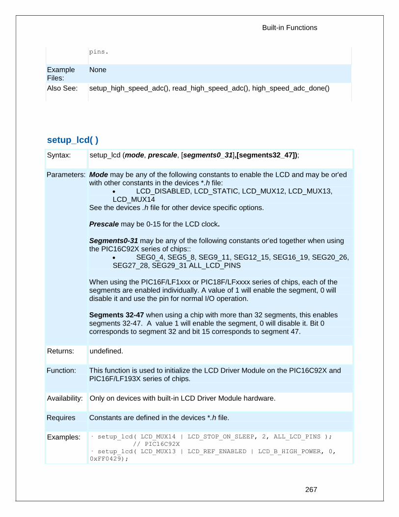
Built-in Functions
267
pins.
Example Files:
None
Also See: setup_high_speed_adc(), read_high_speed_adc(), high_speed_adc_done()
setup_lcd( )
Syntax: setup_lcd (mode, prescale, [segments0_31],[segments32_47]);
Parameters: Mode may be any of the following constants to enable the LCD and may be or'ed with other constants in the devices *.h file:
LCD_DISABLED, LCD_STATIC, LCD_MUX12, LCD_MUX13, LCD_MUX14
See the devices .h file for other device specific options. Prescale may be 0-15 for the LCD clock. Segments0-31 may be any of the following constants or'ed together when using the PIC16C92X series of chips::
SEG0_4, SEG5_8, SEG9_11, SEG12_15, SEG16_19, SEG20_26, SEG27_28, SEG29_31 ALL_LCD_PINS
When using the PIC16F/LF1xxx or PIC18F/LFxxxx series of chips, each of the segments are enabled individually. A value of 1 will enable the segment, 0 will disable it and use the pin for normal I/O operation. Segments 32-47 when using a chip with more than 32 segments, this enables segments 32-47. A value 1 will enable the segment, 0 will disable it. Bit 0 corresponds to segment 32 and bit 15 corresponds to segment 47.
Returns: undefined.
Function: This function is used to initialize the LCD Driver Module on the PIC16C92X and PIC16F/LF193X series of chips.
Availability: Only on devices with built-in LCD Driver Module hardware.
Requires Constants are defined in the devices *.h file.
Examples: · setup_lcd( LCD_MUX14 | LCD_STOP_ON_SLEEP, 2, ALL_LCD_PINS );
// PIC16C92X
· setup_lcd( LCD_MUX13 | LCD_REF_ENABLED | LCD_B_HIGH_POWER, 0,
0xFF0429);

PCD
268
// PIC16F/LF193X – Enables Segments 0, 3, 5, 10, 16, 17,
18, 19, 20, 21, 22, 23
Example Files:
ex_92lcd.c
Also See: lcd_symbol(), lcd_load(), lcd_contrast( ), Internal LCD Overview
setup_low_volt_detect( )
Syntax: setup_low_volt_detect(mode)
Parameters: mode may be one of the constants defined in the devices .h file. LVD_LVDIN, LVD_45, LVD_42, LVD_40, LVD_38, LVD_36, LVD_35, LVD_33, LVD_30, LVD_28, LVD_27, LVD_25, LVD_23, LVD_21, LVD_19 One of the following may be or’ed(via |) with the above if high voltage detect is also available in the device LVD_TRIGGER_BELOW, LVD_TRIGGER_ABOVE
Returns: undefined
Function: This function controls the high/low voltage detect module in the device. The mode constants specifies the voltage trip point and a direction of change from that point (available only if high voltage detect module is included in the device). If the device experiences a change past the trip point in the specified direction the interrupt flag is set and if the interrupt is enabled the execution branches to the interrupt service routine.
Availability: This function is only available with devices that have the high/low voltage detect module.
Requires Constants are defined in the devices.h file.
Examples: setup_low_volt_detect( LVD_TRIGGER_BELOW | LVD_36 );
This would trigger the interrupt when the voltage is below 3.6 volts
setup_nco( )
Syntax: setup_nco(settings,inc_value)
Parameters: settings- setup of the NCO module. See the device's .h file for all options. Some typical options include: · NCO_ENABLE · NCO_OUTPUT · NCO_PULSE_FREQ_MODE
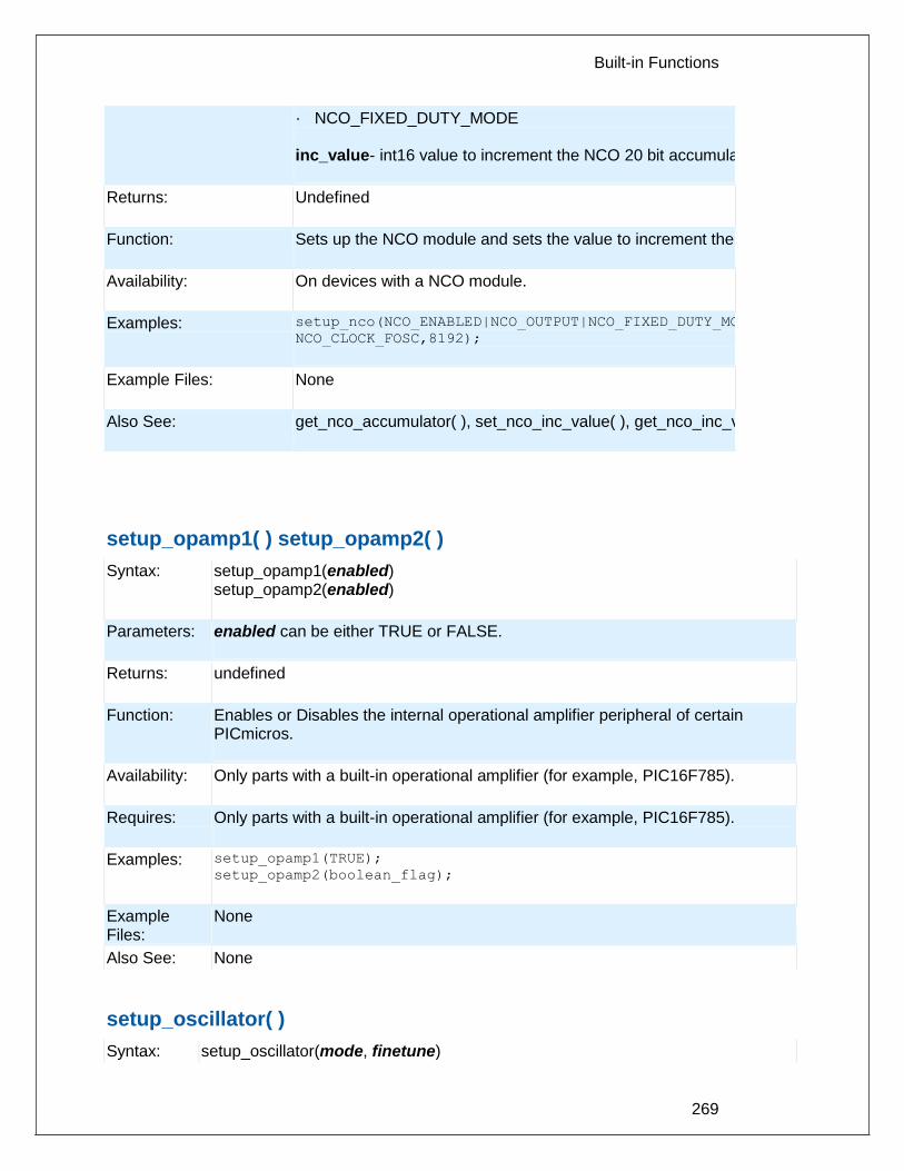
Built-in Functions
269
· NCO_FIXED_DUTY_MODE inc_value- int16 value to increment the NCO 20 bit accumulator by.
Returns: Undefined
Function: Sets up the NCO module and sets the value to increment the 20-bit accumulator by.
Availability: On devices with a NCO module.
Examples: setup_nco(NCO_ENABLED|NCO_OUTPUT|NCO_FIXED_DUTY_MODE|
NCO_CLOCK_FOSC,8192);
Example Files: None
Also See: get_nco_accumulator( ), set_nco_inc_value( ), get_nco_inc_value( )
setup_opamp1( ) setup_opamp2( )
Syntax: setup_opamp1(enabled) setup_opamp2(enabled)
Parameters: enabled can be either TRUE or FALSE.
Returns: undefined
Function: Enables or Disables the internal operational amplifier peripheral of certain PICmicros.
Availability: Only parts with a built-in operational amplifier (for example, PIC16F785).
Requires: Only parts with a built-in operational amplifier (for example, PIC16F785).
Examples: setup_opamp1(TRUE);
setup_opamp2(boolean_flag);
Example Files:
None
Also See: None
setup_oscillator( )
Syntax: setup_oscillator(mode, finetune)

PCD
270
Parameters: mode is dependent on the chip. For example, some chips allow speed setting such as OSC_8MHZ or OSC_32KHZ. Other chips permit changing the source like OSC_TIMER1. The finetune (only allowed on certain parts) is a signed int with a range of -31 to +31.
Returns: Some chips return a state such as OSC_STATE_STABLE to indicate the oscillator is stable .
Function: This function controls and returns the state of the internal RC oscillator on some parts. See the devices .h file for valid options for a particular device. Note that if INTRC or INTRC_IO is specified in #fuses and a #USE DELAY is used for a valid speed option, then the compiler will do this setup automatically at the start of main(). WARNING: If the speed is changed at run time the compiler may not generate the correct delays for some built in functions. The last #USE DELAY encountered in the file is always assumed to be the correct speed. You can have multiple #USE DELAY lines to control the compilers knowledge about the speed.
Availability: Only parts with a OSCCON register.
Requires: Constants are defined in the .h file.
Examples: setup_oscillator( OSC_2MHZ );
Example Files:
None
Also See: #FUSES, Internal oscillator Overview
setup_pmp(option,address_mask)
Syntax: setup_pmp(options,address_mask);
Parameters: options- The mode of the Parallel Master Port that allows to set the Master Port mode, read-write strobe options and other functionality of the PMPort module. See the device's .h file for all options. Some typical options include: · PAR_PSP_AUTO_INC · PAR_CONTINUE_IN_IDLE · PAR_INTR_ON_RW //Interrupt on read write · PAR_INC_ADDR //Increment address by 1 every //read/write cycle · PAR_MASTER_MODE_1 //Master Mode 1

Built-in Functions
271
· PAR_WAITE4 //4 Tcy Wait for data hold after // strobe address_mask- this allows the user to setup the address enable register with a 16-bit value. This value determines which address lines are active from the available 16 address lines PMA0:PMA15.
Returns: Undefined.
Function: Configures various options in the PMP module. The options are present in the device's .h file and they are used to setup the module. The PMP module is highly configurable and this function allows users to setup configurations like the Slave module, Interrupt options, address increment/decrement options, Address enable bits, and various strobe and delay options.
Availability: Only the devices with a built-in Parallel Master Port module.
Requires: Constants are defined in the device's .h file.
Examples: setup_psp(PAR_ENABLE| //Sets up Master mode with address
PAR_MASTER_MODE_1|PAR_ //lines PMA0:PMA7
STOP_IN_IDLE,0x00FF);
Example Files:
None
Also See: setup_pmp( ), pmp_address( ), pmp_read( ), psp_read( ), psp_write( ), pmp_write( ), psp_output_full( ), psp_input_full( ), psp_overflow( ), pmp_output_full( ), pmp_input_full( ), pmp_overflow( ) See header file for device selected
setup_power_pwm( )
Syntax: setup_power_pwm(modes, postscale, time_base, period, compare, compare_postscale, dead_time)
Parameters: modes values may be up to one from each group of the following: PWM_CLOCK_DIV_4, PWM_CLOCK_DIV_16, PWM_CLOCK_DIV_64, PWM_CLOCK_DIV_128 PWM_OFF, PWM_FREE_RUN, PWM_SINGLE_SHOT, PWM_UP_DOWN, PWM_UP_DOWN_INT PWM_OVERRIDE_SYNC PWM_UP_TRIGGER, PWM_DOWN_TRIGGER PWM_UPDATE_DISABLE, PWM_UPDATE_ENABLE

PCD
272
PWM_DEAD_CLOCK_DIV_2, PWM_DEAD_CLOCK_DIV_4, PWM_DEAD_CLOCK_DIV_8, PWM_DEAD_CLOCK_DIV_16 postscale is an integer between 1 and 16. This value sets the PWM time base output postscale. time_base is an integer between 0 and 65535. This is the initial value of the PWM base period is an integer between 0 and 4095. The PWM time base is incremented until it reaches this number. compare is an integer between 0 and 255. This is the value that the PWM time base is compared to, to determine if a special event should be triggered. compare_postscale is an integer between 1 and 16. This postscaler affects compare, the special events trigger. dead_time is an integer between 0 and 63. This value specifies the length of an off period that should be inserted between the going off of a pin and the going on of it is a complementary pin.
Returns: undefined
Function: Initializes and configures the motor control Pulse Width Modulation (PWM) module.
Availability: All devices equipped with motor control or power PWM module.
Requires: None
Examples: setup_power_pwm(PWM_CLOCK_DIV_4 | PWM_FREE_RUN |
PWM_DEAD_CLOCK_DIV_4,1,10000,1000,0,1,0);
Example Files:
None
Also See: set_power_pwm_override(), setup_power_pwm_pins(), set_power_pwmX_duty()
setup_power_pwm_pins( )
Syntax: setup_power_pwm_pins(module0,module1,module2,module3)
Parameters: For each module (two pins) specify: PWM_OFF, PWM_ODD_ON, PWM_BOTH_ON, PWM_COMPLEMENTARY

Built-in Functions
273
Returns: undefined
Function: Configures the pins of the Pulse Width Modulation (PWM) device.
Availability: All devices equipped with a power control PWM.
Requires: None
Examples: setup_power_pwm_pins(PWM_OFF, PWM_OFF, PWM_OFF,
PWM_OFF);
setup_power_pwm_pins(PWM_COMPLEMENTARY,
PWM_COMPLEMENTARY, PWM_OFF, PWM_OFF);
Example Files:
None
Also See: setup_power_pwm(), set_power_pwm_override(),set_power_pwmX_duty()
setup_psp(option,address_mask)
Syntax: setup_psp (options,address_mask); setup_psp(options);
Parameters: Option- The mode of the Parallel slave port. This allows to set the slave port mode, read-write strobe options and other functionality of the PMP/EPMP module. See the devices .h file for all options. Some typical options include: · PAR_PSP_AUTO_INC · PAR_CONTINUE_IN_IDLE · PAR_INTR_ON_RW //Interrupt on read write · PAR_INC_ADDR //Increment address by 1 every //read/write cycle · PAR_WAITE4 //4 Tcy Wait for data hold after //strobe address_mask- This allows the user to setup the address enable register with a 16 bit or 32 bit (EPMP) value. This value determines which address lines are active from the available 16 address lines PMA0: PMA15 or 32 address lines PMAO:PMA31 (EPMP only).
Returns: Undefined.
Function: Configures various options in the PMP/EPMP module. The options are present in the device.h file and they are used to setup the module. The PMP/EPMP module is highly configurable and this function allows users to setup configurations like the Slave mode, Interrupt options, address increment/decrement options, Address

PCD
274
enable bits and various strobe and delay options.
Availability: Only the devices with a built in Parallel Port module or Enhanced Parallel Master Port module.
Requires: Constants are defined in the devices .h file.
Examples: setup_psp(PAR_PSP_AUTO_INC| //Sets up legacy slave
//mode with
PAR_STOP_IN_IDLE,0x00FF ); //read and write buffers
//auto increment.
Example Files:
None
Also See: psp_output_full(), psp_input_full(), psp_overflow(), See header file for device selected.
setup_pwm1( ) setup_pwm2( ) setup_pwm3( ) setup_pwm4( )
Syntax: setup_pwm1(settings); setup_pwm2(settings); setup_pwm3(settings); setup_pwm4(settings);
Parameters: settings- setup of the PWM module. See the device's .h file for all options. Some typical options include: · PWM_ENABLED · PWM_OUTPUT · PWM_ACTIVE_LOW
Returns: Undefined
Function: Sets up the PWM module.
Availability: On devices with a PWM module.
Examples: setup_pwm1(PWM_ENABLED|PWM_OUTPUT);
Example Files:
None
Also See: set_pwm_duty( )

Built-in Functions
275
setup_qei( )
Syntax: setup_qei( options, filter, maxcount );
Parameters: Options- The mode of the QEI module. See the devices .h file for all options Some common options are: · QEI_MODE_X2 · QEI_MODE_X4 filter - This parameter is optional, the user can enable the digital filters and specify the clock divisor. maxcount - Specifies the value at which to reset the position counter.
Returns: void
Function: Configures the Quadrature Encoder Interface. Various settings like mode and filters can be setup.
Availability: Devices that have the QEI module.
Requires: Nothing.
Examples: setup_qei(QEI_MODE_X2|QEI_RESET_WHEN_MAXCOUNT,
QEI_FILTER_ENABLE_QEA|QEI_FILTER_DIV_2,0x1000);
Example Files:
None
Also See: qei_set_count() , qei_get_count() , qei_status()
setup_rtc( )
Syntax: setup_rtc() (options, calibration);
Parameters: Options- The mode of the RTCC module. See the devices .h file for all options Calibration- This parameter is optional and the user can specify an 8 bit value that will get written to the calibration configuration register.
Returns: void
Function: Configures the Real Time Clock and Calendar module. The module requires an external 32.768 kHz clock crystal for operation.
Availability: Devices that have the RTCC module.

PCD
276
Requires: Nothing.
Examples: setup_rtc(RTC_ENABLE | RTC_OUTPUT SECONDS, 0x00);
// Enable RTCC module with seconds clock and no calibration
Example Files:
None
Also See: rtc_read(), rtc_alarm_read(), rtc_alarm_write(), setup_rtc_alarm(), rtc_write(, setup_rtc()
setup_rtc_alarm( )
Syntax: setup_rtc_alarm(options, mask, repeat);
Parameters: options- The mode of the RTCC module. See the devices .h file for all options mask- specifies the alarm mask bits for the alarm configuration. repeat- Specifies the number of times the alarm will repeat. It can have a max value of 255.
Returns: void
Function: Configures the alarm of the RTCC module.
Availability: Devices that have the RTCC module.
Requires: Nothing.
Examples: setup_rtc_alarm(RTC_ALARM_ENABLE, RTC_ALARM_HOUR, 3);
Example Files:
None
Also See: rtc_read(), rtc_alarm_read(), rtc_alarm_write(), setup_rtc_alarm(), rtc_write(), setup_rtc()
setup_spi( ) setup_spi2( )
Syntax: setup_spi (mode) setup_spi2 (mode)

Built-in Functions
277
Parameters: mode may be: SPI_MASTER, SPI_SLAVE, SPI_SS_DISABLED SPI_L_TO_H, SPI_H_TO_L SPI_CLK_DIV_4, SPI_CLK_DIV_16, SPI_CLK_DIV_64, SPI_CLK_T2 SPI_SAMPLE_AT_END, SPI_XMIT_L_TO_H Constants from each group may be or'ed together with |.
Returns: undefined
Function: Initializes the Serial Port Interface (SPI). This is used for 2 or 3 wire serial devices that follow a common clock/data protocol.
Also See: spi_write(), spi_read(), spi_data_is_in(), SPI Overview
setup_timer_A( )
Syntax: setup_timer_A (mode);
Parameters: mode values may be: · TA_OFF, TA_INTERNAL, TA_EXT_H_TO_L, TA_EXT_L_TO_H · TA_DIV_1, TA_DIV_2, TA_DIV_4, TA_DIV_8, TA_DIV_16, TA_DIV_32, TA_DIV_64, TA_DIV_128, TA_DIV_256 · constants from different groups may be or'ed together with |.
Returns: undefined
Function: sets up Timer A.
Availability: This function is only available on devices with Timer A hardware.
Requires: Constants are defined in the device's .h file.
Examples: setup_timer_A(TA_OFF);
setup_timer_A(TA_INTERNAL | TA_DIV_256);
setup_timer_A(TA_EXT_L_TO_H | TA_DIV_1);
Example Files:
none
Also See: get_timerA( ), set_timerA( ), TimerA Overview
setup_timer_B( )
Syntax: setup_timer_B (mode);

PCD
278
Parameters: mode values may be: · TB_OFF, TB_INTERNAL, TB_EXT_H_TO_L, TB_EXT_L_TO_H · TB_DIV_1, TB_DIV_2, TB_DIV_4, TB_DIV_8, TB_DIV_16, TB_DIV_32, TB_DIV_64, TB_DIV_128, TB_DIV_256 · constants from different groups may be or'ed together with |.
Returns: undefined
Function: sets up Timer B
Availability: This function is only available on devices with Timer B hardware.
Requires: Constants are defined in device's .h file.
Examples: setup_timer_B(TB_OFF);
setup_timer_B(TB_INTERNAL | TB_DIV_256);
setup_timer_B(TA_EXT_L_TO_H | TB_DIV_1);
Example Files:
none
Also See: get_timerB( ), set_timerB( ), TimerB Overview
setup_timer_0( )
Syntax: setup_timer_0 (mode)
Parameters: mode may be one or two of the constants defined in the devices .h file. RTCC_INTERNAL, RTCC_EXT_L_TO_H or RTCC_EXT_H_TO_L RTCC_DIV_2, RTCC_DIV_4, RTCC_DIV_8, RTCC_DIV_16, RTCC_DIV_32, RTCC_DIV_64, RTCC_DIV_128, RTCC_DIV_256 PIC18XXX only: RTCC_OFF, RTCC_8_BIT One constant may be used from each group or'ed together with the | operator.
Returns: undefined
Function: Sets up the timer 0 (aka RTCC).
Availability: All devices.

Built-in Functions
279
Requires: Constants are defined in the devices .h file.
Examples: setup_timer_0 (RTCC_DIV_2|RTCC_EXT_L_TO_H);
Example Files:
Also See: get_timer0(), set_timer0(), setup counters()
setup_timer_1( )
Syntax: setup_timer_1 (mode)
Parameters: mode values may be: T1_DISABLED, T1_INTERNAL, T1_EXTERNAL, T1_EXTERNAL_SYNC T1_CLK_OUT T1_DIV_BY_1, T1_DIV_BY_2, T1_DIV_BY_4, T1_DIV_BY_8 constants from different groups may be or'ed together with |.
Returns: undefined
Function: Initializes timer 1. The timer value may be read and written to using SET_TIMER1() and GET_TIMER1()Timer 1 is a 16 bit timer. With an internal clock at 20mhz and with the T1_DIV_BY_8 mode, the timer will increment every 1.6us. It will overflow every 104.8576ms.
Availability: This function is only available on devices with timer 1 hardware.
Requires: Constants are defined in the devices .h file.
Examples: setup_timer_1 ( T1_DISABLED );
setup_timer_1 ( T1_INTERNAL | T1_DIV_BY_4 );
setup_timer_1 ( T1_INTERNAL | T1_DIV_BY_8 );
Example Files:
Also See: get_timer1(), set_timer1() , Timer1 Overview
setup_timer_2( )
Syntax: setup_timer_2 (mode, period, postscale)
Parameters: mode may be one of:

PCD
280
T2_DISABLED, T2_DIV_BY_1, T2_DIV_BY_4, T2_DIV_BY_16 period is a int 0-255 that determines when the clock value is reset, postscale is a number 1-16 that determines how many timer overflows before an interrupt: (1 means once, 2 means twice, and so on).
Returns: undefined
Function: Initializes timer 2. The mode specifies the clock divisor (from the oscillator clock). The timer value may be read and written to using GET_TIMER2() and SET_TIMER2(). Timer 2 is a 8 bit counter/timer.
Availability: This function is only available on devices with timer 2 hardware.
Requires: Constants are defined in the devices .h file.
Examples: setup_timer_2 ( T2_DIV_BY_4, 0xc0, 2);
// At 20mhz, the timer will increment every 800ns,
// will overflow every 154.4us,
// and will interrupt every 308.8us.
Example Files:
Also See: get_timer2(), set_timer2(), Timer2 Overview
setup_timer_3( )
Syntax: setup_timer_3 (mode)
Parameters: Mode may be one of the following constants from each group or'ed (via |) together:
T3_DISABLED, T3_INTERNAL, T3_EXTERNAL, T3_EXTERNAL_SYNC T3_DIV_BY_1, T3_DIV_BY_2, T3_DIV_BY_4, T3_DIV_BY_8
Returns: undefined
Function: Initializes timer 3 or 4.The mode specifies the clock divisor (from the oscillator clock). The timer value may be read and written to using GET_TIMER3() and SET_TIMER3(). Timer 3 is a 16 bit counter/timer.
Availability: This function is only available on devices with timer 3 hardware.
Requires: Constants are defined in the devices .h file.

Built-in Functions
281
Examples: setup_timer_3 (T3_INTERNAL | T3_DIV_BY_2);
Example Files:
None
Also See: get_timer3(), set_timer3()
setup_timer_4( )
Syntax: setup_timer_4 (mode, period, postscale)
Parameters: mode may be one of: T4_DISABLED, T4_DIV_BY_1, T4_DIV_BY_4, T4_DIV_BY_16
period is a int 0-255 that determines when the clock value is reset, postscale is a number 1-16 that determines how many timer overflows before an interrupt: (1 means once, 2 means twice, and so on).
Returns: undefined
Function: Initializes timer 4. The mode specifies the clock divisor (from the oscillator clock). The timer value may be read and written to using GET_TIMER4() and SET_TIMER4(). Timer 4 is a 8 bit counter/timer.
Availability: This function is only available on devices with timer 4 hardware.
Requires: Constants are defined in the devices .h file
Examples: setup_timer_4 ( T4_DIV_BY_4, 0xc0, 2);
// At 20mhz, the timer will increment every 800ns,
// will overflow every 153.6us,
// and will interrupt every 307.2us.
Example Files:
Also See: get_timer4(), set_timer4()
setup_timer_5( )
Syntax: setup_timer_5 (mode)

PCD
282
Parameters: mode may be one or two of the constants defined in the devices .h file. T5_DISABLED, T5_INTERNAL, T5_EXTERNAL, or T5_EXTERNAL_SYNC T5_DIV_BY_1, T5_DIV_BY_2, T5_DIV_BY_4, T5_DIV_BY_8 T5_ONE_SHOT, T5_DISABLE_SE_RESET, or T5_ENABLE_DURING_SLEEP
Returns: undefined
Function: Initializes timer 5. The mode specifies the clock divisor (from the oscillator clock). The timer value may be read and written to using GET_TIMER5() and SET_TIMER5(). Timer 5 is a 16 bit counter/timer.
Availability: This function is only available on devices with timer 5 hardware.
Requires: Constants are defined in the devices .h file.
Examples: setup_timer_5 (T5_INTERNAL | T5_DIV_BY_2);
Example Files:
None
Also See: get_timer5(), set_timer5(), Timer5 Overview
setup_uart( )
Syntax: setup_uart(baud, stream) setup_uart(baud) setup_uart(baud, stream, clock)
Parameters: baud is a constant representing the number of bits per second. A one or zero may also be passed to control the on/off status. Stream is an optional stream identifier. Chips with the advanced UART may also use the following constants: UART_ADDRESS UART only accepts data with 9th bit=1 UART_DATA UART accepts all data Chips with the EUART H/W may use the following constants: UART_AUTODETECT Waits for 0x55 character and sets the UART baud rate to match. UART_AUTODETECT_NOWAIT Same as above function, except returns before 0x55 is received. KBHIT() will be true when the match is made. A call to GETC() will clear the character. UART_WAKEUP_ON_RDA Wakes PIC up out of sleep when RCV goes from high to low

Built-in Functions
283
clock - If specified this is the clock rate this function should assume. The default comes from the #USE DELAY.
Returns: undefined
Function: Very similar to SET_UART_SPEED. If 1 is passed as a parameter, the UART is turned on, and if 0 is passed, UART is turned off. If a BAUD rate is passed to it, the UART is also turned on, if not already on.
Availability: This function is only available on devices with a built in UART.
Requires: #USE RS232
Examples: setup_uart(9600);
setup_uart(9600, rsOut);
Example Files:
None
Also See: #USE RS232, putc(), getc(), RS232 I/O Overview
setup_vref( )
Syntax: setup_vref (mode | value )
Parameters: mode may be one of the following constants: FALSE (off) VREF_LOW for VDD*VALUE/24 VREF_HIGH for VDD*VALUE/32 + VDD/4 any may be or'ed with VREF_A2.
value is an int 0-15.
Also See: Voltage Reference Overview
setup_wdt( )
Syntax: setup_wdt (mode)
Parameters: Constants like: WDT_18MS, WDT_36MS, WDT_72MS, WDT_144MS,WDT_288MS, WDT_576MS, WDT_1152MS, WDT_2304MS For some parts: WDT_ON, WDT_OFF .

PCD
284
Also See:
#FUSES , restart_wdt() , WDT or Watch Dog Timer Overview Internal Oscillator Overview
shift_left( )
Syntax: shift_left (address, bytes, value)
Parameters: address is a pointer to memory. bytes is a count of the number of bytes to work with value is a 0 to 1 to be shifted in.
Returns: 0 or 1 for the bit shifted out
Function: Shifts a bit into an array or structure. The address may be an array identifier or an address to a structure (such as &data). Bit 0 of the lowest byte in RAM is treated as the LSB.
Availability: All devices
Requires: Nothing
Examples: byte buffer[3];
for(i=0; i<=24; ++i){
// Wait for clock high
while (!input(PIN_A2));
shift_left(buffer,3,input(PIN_A3));
// Wait for clock low
while (input(PIN_A2));
}
// reads 24 bits from pin A3,each bit is read
// on a low to high on pin A2
Example Files:
ex_extee.c, 9356.c
Also See: shift_right(), rotate_right(), rotate_left(),
shift_right( )
Syntax: shift_right (address, bytes, value)
Parameters: address is a pointer to memory bytes is a count of the number of bytes to work with value is a 0 to 1 to be shifted in.
Returns: 0 or 1 for the bit shifted out

Built-in Functions
285
Function: Shifts a bit into an array or structure. The address may be an array identifier or an address to a structure (such as &data). Bit 0 of the lowest byte in RAM is treated as the LSB.
Availability: All devices
Requires: Nothing
Examples: // reads 16 bits from pin A1, each bit is read
// on a low to high on pin A2
struct {
byte time;
byte command : 4;
byte source : 4;} msg;
for(i=0; i<=16; ++i) {
while(!input(PIN_A2));
shift_right(&msg,3,input(PIN_A1));
while (input(PIN_A2)) ;}
// This shifts 8 bits out PIN_A0, LSB first.
for(i=0;i<8;++i)
output_bit(PIN_A0,shift_right(&data,1,0));
Example Files:
ex_extee.c, 9356.c
Also See: shift_left(), rotate_right(), rotate_left(),
sleep( )
Syntax: sleep(mode)
Parameters: mode - for most chips this is not used. Check the device header for special options on some chips.
Returns: Undefined
Function: Issues a SLEEP instruction. Details are device dependent. However, in general the part will enter low power mode and halt program execution until woken by specific external events. Depending on the cause of the wake up execution may continue after the sleep instruction. The compiler inserts a sleep() after the last statement in main().
Availability: All devices

PCD
286
Requires: Nothing
Examples: SLEEP();
Example Files:
ex_wakup.c
Also See: reset cpu()
sleep_ulpwu( )
Syntax: sleep_ulpwu(time)
Parameters: time specifies how long, in us, to charge the capacitor on the ultra-low power wakeup pin (by outputting a high on PIN_A0).
Returns: undefined
Function: Charges the ultra-low power wake-up capacitor on PIN_A0 for time microseconds, and then puts the PIC to sleep. The PIC will then wake-up on an 'Interrupt-on-Change' after the charge on the cap is lost.
Availability: Ultra Low Power Wake-Up support on the PIC (example, PIC12F683)
Requires: #USE DELAY
Examples: while(TRUE)
{
if (input(PIN_A1))
//do something
else
sleep_ulpwu(10); //cap will be charged for 10us,
//then goto sleep
}
Example Files:
None
Also See: #USE DELAY
spi_data_is_in( ) spi_data_is_in2( )
Syntax: result = spi_data_is_in() result = spi_data_is_in2()
Parameters: None
Returns: 0 (FALSE) or 1 (TRUE)
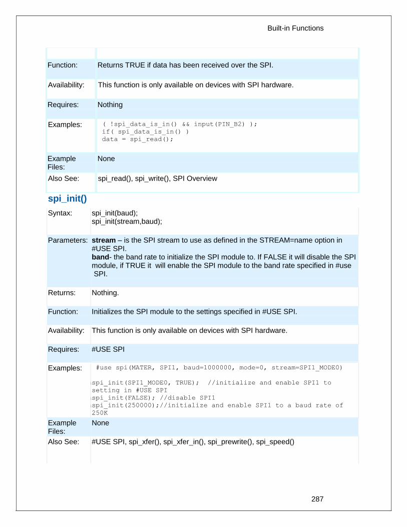
Built-in Functions
287
Function: Returns TRUE if data has been received over the SPI.
Availability: This function is only available on devices with SPI hardware.
Requires: Nothing
Examples: while ( !spi_data_is_in() && input(PIN_B2) );
if( spi_data_is_in() )
data = spi_read();
Example Files:
None
Also See: spi_read(), spi_write(), SPI Overview
spi_init()
Syntax: spi_init(baud); spi_init(stream,baud);
Parameters: stream – is the SPI stream to use as defined in the STREAM=name option in #USE SPI. band- the band rate to initialize the SPI module to. If FALSE it will disable the SPI module, if TRUE it will enable the SPI module to the band rate specified in #use SPI.
Returns: Nothing.
Function: Initializes the SPI module to the settings specified in #USE SPI.
Availability: This function is only available on devices with SPI hardware.
Requires: #USE SPI
Examples: while #use spi(MATER, SPI1, baud=1000000, mode=0, stream=SPI1_MODE0)
spi_inspi_init(SPI1_MODE0, TRUE); //initialize and enable SPI1 to
setting in #USE SPI
spi_inspi_init(FALSE); //disable SPI1
spi_inspi_init(250000);//initialize and enable SPI1 to a baud rate of
250K
Example Files:
None
Also See: #USE SPI, spi_xfer(), spi_xfer_in(), spi_prewrite(), spi_speed()

PCD
288
spi_prewrite(data);
Syntax: spi_prewrite(data); spi_prewrite(stream, data);
Parameters: stream – is the SPI stream to use as defined in the STREAM=name option in #USE SPI. data- the variable or constant to transfer via SPI
Returns: Nothing.
Function: Writes data into the SPI buffer without waiting for transfer to be completed. Can be used in conjunction with spi_xfer() with no parameters to transfer more then 8 bits for PCM and PCH device, or more then 8 bits or 16 bits (XFER16 option) for PCD. Function is useful when using the SSP or SSP2 interrupt service routines for PCM and PCH device, or the SPIx interrupt service routines for PCD device.
Availability: This function is only available on devices with SPI hardware.
Requires: #USE SPI, and the option SLAVE is used in #USE SPI to setup PIC as a SPI slave device
Examples: spi_prewrite(data_out);
Example Files:
ex_spi_slave.c
Also See: #USE SPI, spi_xfer(), spi_xfer_in(), spi_init(), spi_speed()
spi_read( ) spi_read2( )
Syntax: value = spi_read ([data]) value = spi_read2 ([data])
Parameters: data – optional parameter and if included is an 8 bit int.
Returns: An 8 bit int
Function: Return a value read by the SPI. If a value is passed to the spi_read() the data will be clocked out and the data received will be returned. If no data is ready, spi_read() will wait for the data is a SLAVE or return the last DATA clocked in from spi_write(). If this device is the MASTER then either do a spi_write(data) followed by a spi_read() or do a spi_read(data). These both do the same thing and will generate a clock. If there is no data to send just do a spi_read(0) to get the clock. If this device is a SLAVE then either call spi_read() to wait for the clock and data or use_spi_data_is_in() to determine if data is ready.
Availability: This function is only available on devices with SPI hardware.

Built-in Functions
289
Requires: Nothing
Examples: data_in = spi_read(out_data);
Example Files:
ex_spi.c
Also See: spi_write(), , , spi_data_is_in(), SPI Overview
spi_read_16()
spi_read2_16()
spi_read3_16()
spi_read4_16()
Syntax: value = spi_read_16([data]); value = spi_read2_16([data]); value = spi_read3_16([data]); value = spi_read4_16([data]);
Parameters: data – optional parameter and if included is a 16 bit int
Returns: A 16 bit int
Function: Return a value read by the SPI. If a value is passed to the spi_read_16() the data will be clocked out and the data received will be returned. If no data is ready, spi_read_16() will wait for the data is a SLAVE or return the last DATA clocked in from spi_write_16(). If this device is the MASTER then either do a spi_write_16(data) followed by a spi_read_16() or do a spi_read_16(data). These both do the same thing and will generate a clock. If there is no data to send just do a spi_read_16(0) to get the clock. If this device is a slave then either call spi_read_16() to wait for the clock and data or use_spi_data_is_in() to determine if data is ready.
Availability: This function is only available on devices with SPI hardware.
Requires: NThat the option SPI_MODE_16B be used in setup_spi() function, or that the option XFER16 be used in #use SPI(
Examples: data_in = spi_read_16(out_data);
Example Files:
None
Also See: spi_read(), spi_write(), spi_write_16(), spi_data_is_in(), SPI Overview

PCD
290
spi_speed
Syntax: spi_speed(baud); spi_speed(stream,baud); spi_speed(stream,baud,clock);
Parameters: stream – is the SPI stream to use as defined in the STREAM=name option in #USE SPI. band- the band rate to set the SPI module to clock- the current clock rate to calculate the band rate with. If not specified it uses the value specified in #use delay ().
Returns: Nothing.
Function: Sets the SPI module's baud rate to the specified value.
Availability: This function is only available on devices with SPI hardware.
Requires: #USE SPI
Examples: spi_speed(250000); spi_speed(SPI1_MODE0, 250000); spi_speed(SPI1_MODE0, 125000, 8000000);
Example Files:
None
Also See: #USE SPI, spi_xfer(), spi_xfer_in(), spi_prewrite(), spi_init()
spi_write( ) spi_write2( )
Syntax: spi_write([wait],value); spi_write2([wait],value);
Parameters: value is an 8 bit int wait- an optional parameter specifying whether the function will wait for the SPI transfer to complete before exiting. Default is TRUE if not specified.
Returns: Nothing
Function: Sends a byte out the SPI interface. This will cause 8 clocks to be generated. This function will write the value out to the SPI. At the same time data is clocked out data is clocked in and stored in a receive buffer. spi_read() may be used to read the buffer.
Availability: This function is only available on devices with SPI hardware.

Built-in Functions
291
Requires: Nothing
Examples: spi_write( data_out );
data_in = spi_read();
Example Files:
ex_spi.c
Also See: spi_read(), spi_data_is_in(), SPI Overview, spi_write_16(), spi_read_16()
spi_xfer( )
Syntax: spi_xfer(data) spi_xfer(stream, data) spi_xfer(stream, data, bits) result = spi_xfer(data) result = spi_xfer(stream, data) result = spi_xfer(stream, data, bits)
Parameters: data is the variable or constant to transfer via SPI. The pin used to transfer data is defined in the DO=pin option in #use spi. stream is the SPI stream to use as defined in the STREAM=name option in #USE SPI. bits is how many bits of data will be transferred.
Returns: The data read in from the SPI. The pin used to transfer result is defined in the DI=pin option in #USE SPI.
Function: Transfers data to and reads data from an SPI device.
Availability: All devices with SPI support.
Requires: #USE SPI
Examples: int i = 34;
spi_xfer(i);
// transfers the number 34 via SPI
int trans = 34, res;
res = spi_xfer(trans);
// transfers the number 34 via SPI
// also reads the number coming in from SPI
Example Files:
None
Also See: #USE SPI

PCD
292
SPII_XFER_IN()
Syntax: value = spi_xfer_in(); value = spi_xfer_in(bits); value = spi_xfer_in(stream,bits);
Parameters: stream – is the SPI stream to use as defined in the STREAM=name option in #USE SPI. bits – is how many bits of data to be received.
Returns: The data read in from the SPI
Function: Reads data from the SPI, without writing data into the transmit buffer first.
Availability: This function is only available on devices with SPI hardware.
Requires: #USE SPI, and the option SLAVE is used in #USE SPI to setup PIC as a SPI slave device.
Examples: data_in = spi_xfer_in();
Example Files:
ex_spi_slave.c
Also See: #USE SPI, spi_xfer(), spi_prewrite(), spi_init(), spi_speed()
sprintf( )
Syntax: sprintf(string, cstring, values...); bytes=sprintf(string, cstring, values...)
Parameters: string is an array of characters. cstring is a constant string or an array of characters null terminated. Values are a list of variables separated by commas. Note that format specifies do not work in ram band strings.
Returns: Bytes is the number of bytes written to string.
Function: This function operates like printf() except that the output is placed into the specified string. The output string will be terminated with a null. No checking is done to ensure the string is large enough for the data. See printf() for details on formatting.
Availability: All devices.
Requires: Nothing
Examples: char mystring[20];
long mylong;
mylong=1234;

Built-in Functions
293
sprintf(mystring,"<%lu>",mylong);
// mystring now has:
// < 1 2 3 4 > \0
Example Files:
None
Also See: printf()
sqrt( )
Syntax: result = sqrt (value)
Parameters: value is a float
Returns: A float
Function: Computes the non-negative square root of the float value x. If the argument is negative, the behavior is undefined. Note on error handling: If "errno.h" is included then the domain and range errors are stored in the errno variable. The user can check the errno to see if an error has occurred and print the error using the perror function. Domain error occurs in the following cases: sqrt: when the argument is negative
Availability: All devices.
Requires: #INCLUDE <math.h>
Examples: distance = sqrt( pow((x1-x2),2)+pow((y1-y2),2) );
Example Files:
None
Also See: None
srand( )
Syntax: srand(n)
Parameters: n is the seed for a new sequence of pseudo-random numbers to be returned by subsequent calls to rand.

PCD
294
Returns: No value.
Function: The srand() function uses the argument as a seed for a new sequence of pseudo-random numbers to be returned by subsequent calls to rand. If srand() is then called with same seed value, the sequence of random numbers shall be repeated. If rand is called before any call to srand() have been made, the same sequence shall be generated as when srand() is first called with a seed value of 1.
Availability: All devices.
Requires: #INCLUDE <STDLIB.H>
Examples: srand(10);
I=rand();
Example Files:
None
Also See: rand()
STANDARD STRING FUNCTIONS( ) memchr( ) memcmp( ) strcat( ) strchr( ) strcmp( ) strcoll( ) strcspn( ) strerror( ) stricmp( ) strlen( ) strlwr( ) strncat( ) strncmp( ) strncpy( ) strpbrk( ) strrchr( ) strspn( ) strstr( ) strxfrm( )
Syntax: ptr=strcat (s1, s2) Concatenate s2 onto s1
ptr=strchr (s1, c) Find c in s1 and return &s1[i]
ptr=strrchr (s1, c) Same but search in reverse
cresult=strcmp (s1, s2) Compare s1 to s2
iresult=strncmp (s1, s2, n) Compare s1 to s2 (n bytes)
iresult=stricmp (s1, s2) Compare and ignore case
ptr=strncpy (s1, s2, n) Copy up to n characters s2->s1
iresult=strcspn (s1, s2) Count of initial chars in s1 not in s2
iresult=strspn (s1, s2) Count of initial chars in s1 also in s2
iresult=strlen (s1) Number of characters in s1
ptr=strlwr (s1) Convert string to lower case
ptr=strpbrk (s1, s2) Search s1 for first char also in s2
ptr=strstr (s1, s2) Search for s2 in s1
ptr=strncat(s1,s2) Concatenates up to n bytes of s2 onto s1
iresult=strcoll(s1,s2) Compares s1 to s2, both interpreted as appropriate to the current locale.
res=strxfrm(s1,s2,n) Transforms maximum of n characters of s2 and places them in s1, such that strcmp(s1,s2) will give the same result as strcoll(s1,s2)

Built-in Functions
295
iresult=memcmp(m1,m2,n) Compare m1 to m2 (n bytes)
ptr=memchr(m1,c,n) Find c in first n characters of m1 and return &m1[i]
ptr=strerror(errnum) Maps the error number in errnum to an error message string. The parameters 'errnum' is an unsigned 8 bit int. Returns a pointer to the string.
Parameters: s1 and s2 are pointers to an array of characters (or the name of an array). Note that s1 and s2 MAY NOT BE A CONSTANT (like "hi"). n is a count of the maximum number of character to operate on. c is a 8 bit character m1 and m2 are pointers to memory.
Returns: ptr is a copy of the s1 pointer iresult is an 8 bit int result is -1 (less than), 0 (equal) or 1 (greater than) res is an integer.
Function: Functions are identified above.
Availability: All devices.
Requires: #include <string.h>
Examples: char string1[10], string2[10];
strcpy(string1,"hi ");
strcpy(string2,"there");
strcat(string1,string2);
printf("Length is %u\r\n", strlen(string1));
// Will print 8
Example Files:
ex_str.c
Also See: strcpy(), strtok()
strtod( )
Syntax: result=strtod(nptr,& endptr)

PCD
296
Parameters: nptr and endptr are strings
Returns: result is a float. returns the converted value in result, if any. If no conversion could be performed, zero is returned.
Function: The strtod function converts the initial portion of the string pointed to by nptr to a float representation. The part of the string after conversion is stored in the object pointed to endptr, provided that endptr is not a null pointer. If nptr is empty or does not have the expected form, no conversion is performed and the value of nptr is stored in the object pointed to by endptr, provided endptr is not a null pointer.
Availability: All devices.
Requires: #INCLUDE <stdlib.h>
Examples: float result;
char str[12]="123.45hello";
char *ptr;
result=strtod(str,&ptr);
//result is 123.45 and ptr is "hello"
Example Files:
None
Also See: strtol(), strtoul()
strtok( )
Syntax: ptr = strtok(s1, s2)
Parameters: s1 and s2 are pointers to an array of characters (or the name of an array). Note that s1 and s2 MAY NOT BE A CONSTANT (like "hi"). s1 may be 0 to indicate a continue operation.
Returns: ptr points to a character in s1 or is 0
Function: Finds next token in s1 delimited by a character from separator string s2 (which can be different from call to call), and returns pointer to it. First call starts at beginning of s1 searching for the first character NOT contained in s2 and returns null if there is none are found. If none are found, it is the start of first token (return value). Function then searches from there for a character contained in s2.

Built-in Functions
297
If none are found, current token extends to the end of s1, and subsequent searches for a token will return null. If one is found, it is overwritten by '\0', which terminates current token. Function saves pointer to following character from which next search will start. Each subsequent call, with 0 as first argument, starts searching from the saved pointer.
Availability: All devices.
Requires: #INCLUDE <string.h>
Examples: char string[30], term[3], *ptr;
strcpy(string,"one,two,three;");
strcpy(term,",;");
ptr = strtok(string, term);
while(ptr!=0) {
puts(ptr);
ptr = strtok(0, term);
}
// Prints:
one
two
three
Example Files:
ex_str.c
Also See: strxxxx(), strcpy()
strtol( )
Syntax: result=strtol(nptr,& endptr, base)
Parameters: nptr and endptr are strings and base is an integer
Returns: result is a signed long int. returns the converted value in result , if any. If no conversion could be performed, zero is returned.
Function: The strtol function converts the initial portion of the string pointed to by nptr to a signed long int representation in some radix determined by the value of base. The part of the string after conversion is stored in the object pointed to endptr, provided that endptr is not a null pointer. If nptr is empty or does not have the expected form, no conversion is performed and the value of nptr is stored in the object pointed to by endptr, provided endptr is not a null pointer.

PCD
298
Availability: All devices.
Requires: #INCLUDE <stdlib.h>
Examples: signed long result;
char str[9]="123hello";
char *ptr;
result=strtol(str,&ptr,10);
//result is 123 and ptr is "hello"
Example Files:
None
Also See: strtod(), strtoul()
strtoul( )
Syntax: result=strtoul(nptr,endptr, base)
Parameters: nptr and endptr are strings pointers and base is an integer 2-36.
Returns: result is an unsigned long int. returns the converted value in result , if any. If no conversion could be performed, zero is returned.
Function: The strtoul function converts the initial portion of the string pointed to by nptr to a long int representation in some radix determined by the value of base. The part of the string after conversion is stored in the object pointed to endptr, provided that endptr is not a null pointer. If nptr is empty or does not have the expected form, no conversion is performed and the value of nptr is stored in the object pointed to by endptr, provided endptr is not a null pointer.
Availability: All devices.
Requires: STDLIB.H must be included
Examples: long result;
char str[9]="123hello";
char *ptr;
result=strtoul(str,&ptr,10);
//result is 123 and ptr is "hello"
Example Files:
None

Built-in Functions
299
Also See: strtol(), strtod()
swap( )
Syntax: swap (lvalue)
Parameters: lvalue is a byte variable
Returns: undefined - WARNING: this function does not return the result
Function: Swaps the upper nibble with the lower nibble of the specified byte. This is the same as: byte = (byte << 4) | (byte >> 4);
Availability: All devices.
Requires: Nothing
Examples: x=0x45;
swap(x);
//x now is 0x54
Example Files:
None
Also See: rotate_right(), rotate_left()
tolower( ) toupper( )
Syntax: result = tolower (cvalue) result = toupper (cvalue)
Parameters: cvalue is a character
Returns: An 8 bit character
Function: These functions change the case of letters in the alphabet. TOLOWER(X) will return 'a'..'z' for X in 'A'..'Z' and all other characters are unchanged. TOUPPER(X) will return 'A'..'Z' for X in 'a'..'z' and all other characters are unchanged.
Availability: All devices.
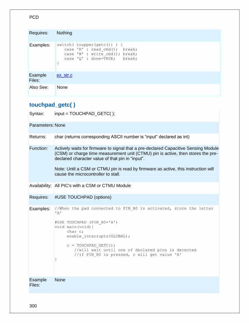
PCD
300
Requires: Nothing
Examples: switch( toupper(getc()) ) {
case 'R' : read_cmd(); break;
case 'W' : write_cmd(); break;
case 'Q' : done=TRUE; break;
}
Example Files:
ex_str.c
Also See: None
touchpad_getc( )
Syntax: input = TOUCHPAD_GETC( );
Parameters: None
Returns: char (returns corresponding ASCII number is “input” declared as int)
Function: Actively waits for firmware to signal that a pre-declared Capacitive Sensing Module (CSM) or charge time measurement unit (CTMU) pin is active, then stores the pre-declared character value of that pin in “input”. Note: Until a CSM or CTMU pin is read by firmware as active, this instruction will cause the microcontroller to stall.
Availability: All PIC's with a CSM or CTMU Module
Requires: #USE TOUCHPAD (options)
Examples: //When the pad connected to PIN_B0 is activated, store the letter
'A'
#USE TOUCHPAD (PIN_B0='A')
void main(void){
char c;
enable_interrupts(GLOBAL);
c = TOUCHPAD_GETC();
//will wait until one of declared pins is detected
//if PIN_B0 is pressed, c will get value 'A'
}
Example Files:
None

Built-in Functions
301
Also See: #USE TOUCHPAD, touchpad_state( )
touchpad_hit( )
Syntax: value = TOUCHPAD_HIT( )
Parameters: None
Returns: TRUE or FALSE
Function: Returns TRUE if a Capacitive Sensing Module (CSM) or Charge Time Measurement Unit (CTMU) key has been pressed. If TRUE, then a call to touchpad_getc() will not cause the program to wait for a key press.
Availability: All PIC's with a CSM or CTMU Module
Requires: #USE TOUCHPAD (options)
Examples: // When the pad connected to PIN_B0 is activated, store the letter
'A'
#USE TOUCHPAD (PIN_B0='A')
void main(void){
char c;
enable_interrupts(GLOBAL);
while (TRUE) {
if ( TOUCHPAD_HIT() )
//wait until key on PIN_B0 is pressed
c = TOUCHPAD_GETC(); //get key that was pressed
} //c will get value 'A'
}
Example Files:
None
Also See:
#USE TOUCHPAD ( ), touchpad_state( ), touchpad_getc( )
touchpad_state( )
Syntax: TOUCHPAD_STATE (state);
Parameters: state is a literal 0, 1, or 2.
Returns: None
Function: Sets the current state of the touchpad connected to the Capacitive Sensing Module (CSM). The state can be one of the following three values:

PCD
302
0 : Normal state 1 : Calibrates, then enters normal state 2 : Test mode, data from each key is collected in the int16 array TOUCHDATA Note: If the state is set to 1 while a key is being pressed, the touchpad will not calibrate properly.
Availability: All PIC's with a CSM Module
Requires: #USE TOUCHPAD (options)
Examples: #USE TOUCHPAD (THRESHOLD=5, PIN_D5='5', PIN_B0='C')
void main(void){
char c;
TOUCHPAD_STATE(1); //calibrates, then enters normal state
enable_interrupts(GLOBAL);
while(1){
c = TOUCHPAD_GETC();
//will wait until one of declared pins is detected
}
//if PIN_B0 is pressed, c will get value 'C'
} //if PIN_D5 is pressed, c will get value '5'
Example Files:
None
Also See:
#USE TOUCHPAD, touchpad_getc( ), touchpad_hit( )
tx_buffer_bytes()
Syntax: value = tx_buffer_bytes([stream]);
Parameters: stream – optional parameter specifying the stream defined in #USE RS232.
Returns: Number of bytes in transmit buffer that still need to be sent.
Function: Function to determine the number of bytes in transmit buffer that still need to be sent.
Availability: All devices
Requires: #USE RS232
Examples: #USE_RS232(UART1,BAUD=9600,TRANSMIT_BUFFER=50) void main(void) { char string[] = “Hello”; if(tx_buffer_bytes() <= 45) printf(“%s”,string); }
Example Files:
None
Also See: _USE_RS232( ), RCV_BUFFER_FULL( ), TX_BUFFER_FULL( ), RCV_BUFFER_BYTES( ), GET( ), PUTC( ) ,PRINTF( ), SETUP_UART( ),

Built-in Functions
303
PUTC_SEND( )
.
tx_buffer_full( )
Syntax: value = tx_buffer_full([stream])
Parameters: stream – optional parameter specifying the stream defined in #USE RS232
Returns: TRUE if transmit buffer is full, FALSE otherwise.
Function: Function to determine if there is room in transmit buffer for another character.
Availability: All devices
Requires: #USE RS232
Examples: #USE_RS232(UART1,BAUD=9600,TRANSMIT_BUFFER=50) void main(void) { char c; if(!tx_buffer_full()) putc(c); }
Example Files:
None
Also See: _USE_RS232( ), RCV_BUFFER_FULL( ), TX_BUFFER_FULL( )., RCV_BUFFER_BYTES( ), GETC( ), PUTC( ), PRINTF( ), SETUP_UART( )., PUTC_SEND( )
va_arg( )
Syntax: va_arg(argptr, type)
Parameters: argptr is a special argument pointer of type va_list type – This is data type like int or char.
Returns: The first call to va_arg after va_start return the value of the parameters after that specified by the last parameter. Successive invocations return the values of the remaining arguments in succession.
Function: The function will return the next argument every time it is called.
Availability: All devices.
Requires: #INCLUDE <stdarg.h>
Examples: int foo(int num, ...)
{
int sum = 0;

PCD
304
int i;
va_list argptr; // create special argument pointer
va_start(argptr,num); // initialize argptr
for(i=0; i<num; i++)
sum = sum + va_arg(argptr, int);
va_end(argptr); // end variable processing
return sum;
}
Example Files:
None
Also See: nargs(), va_end(), va_start()
va_end( )
Syntax: va_end(argptr)
Parameters: argptr is a special argument pointer of type va_list.
Returns: None
Function: A call to the macro will end variable processing. This will facillitate a normal return from the function whose variable argument list was referred to by the expansion of va_start().
Availability: All devices.
Requires: #INCLUDE <stdarg.h>
Examples: int foo(int num, ...)
{
int sum = 0;
int i;
va_list argptr; // create special argument pointer
va_start(argptr,num); // initialize argptr
for(i=0; i<num; i++)
sum = sum + va_arg(argptr, int);
va_end(argptr); // end variable processing
return sum;
}
Example Files:
None
Also See: nargs(), va_start(), va_arg()

Built-in Functions
305
va_start
Syntax: va_start(argptr, variable)
Parameters: argptr is a special argument pointer of type va_list variable – The second parameter to va_start() is the name of the last parameter before the variable-argument list.
Returns: None
Function: The function will initialize the argptr using a call to the macro va_start().
Availability: All devices.
Requires: #INCLUDE <stdarg.h>
Examples: int foo(int num, ...)
{
int sum = 0;
int i;
va_list argptr; // create special argument pointer
va_start(argptr,num); // initialize argptr
for(i=0; i<num; i++)
sum = sum + va_arg(argptr, int);
va_end(argptr); // end variable processing
return sum;
}
Example Files:
None
Also See: nargs(), va_start(), va_arg()
write_bank( )
Syntax: write_bank (bank, offset, value)
Parameters: bank is the physical RAM bank 1-3 (depending on the device) offset is the offset into user RAM for that bank (starts at 0) value is the 8 bit data to write
Returns: undefined
Function: Write a data byte to the user RAM area of the specified memory bank. This function may be used on some devices where full RAM access by auto variables is not efficient. For example on the PIC16C57 chip setting the pointer size to 5 bits will generate the most efficient ROM code however auto variables can not be above 1Fh. Instead of going to 8 bit pointers you can save ROM by using this

PCD
306
function to write to the hard to reach banks. In this case the bank may be 1-3 and the offset may be 0-15.
Availability: All devices but only useful on PCB parts with memory over 1Fh and PCM parts with memory over FFh.
Requires: Nothing
Examples: i=0; // Uses bank 1 as a RS232 buffer
do {
c=getc();
write_bank(1,i++,c);
} while (c!=0x13);
Example Files:
ex_psp.c
Also See: See the "Common Questions and Answers" section for more information.
write_configuration_memory( )
Syntax: write_configuration_memory (dataptr, count)
Parameters: dataptr: pointer to one or more bytes count: a 8 bit integer
Returns: undefined
Function: Erases all fuses and writes count bytes from the dataptr to the configuration memory.
Availability: All PIC18 flash devices
Requires: Nothing
Examples: int data[6];
write_configuration_memory(data,6)
Example Files:
None
Also See: WRITE_PROGRAM_MEMORY(), Configuration Memory Overview
write_eeprom( )
Syntax: write_eeprom (address, value)

Built-in Functions
307
Parameters: address is a (8 bit or 16 bit depending on the part) int, the range is device dependent value is an 8 bit int
Returns: undefined
Function: Write a byte to the specified data EEPROM address. This function may take several milliseconds to execute. This works only on devices with EEPROM built into the core of the device. For devices with external EEPROM or with a separate EEPROM in the same package (like the 12CE671) see EX_EXTEE.c with CE51X.c, CE61X.c or CE67X.c. In order to allow interrupts to occur while using the write operation, use the #DEVICE option WRITE_EEPROM = NOINT. This will allow interrupts to occur while the write_eeprom() operations is polling the done bit to check if the write operations has completed. Can be used as long as no EEPROM operations are performed during an ISR.
Availability: This function is only available on devices with supporting hardware on chip.
Requires: Nothing
Examples: #define LAST_VOLUME 10 // Location in EEPROM
volume++;
write_eeprom(LAST_VOLUME,volume);
Example Files:
ex_intee.c, ex_extee.c, ce51x.c, ce62x.c, ce67x.c
Also See: read_eeprom(), write_program_eeprom(), read_program_eeprom(), data Eeprom Overview
write_external_memory( )
Syntax: write_external_memory( address, dataptr, count )
Parameters: address is 16 bits on PCM parts and 32 bits on PCH parts dataptr is a pointer to one or more bytes count is a 8 bit integer
Returns: undefined
Function: Writes count bytes to program memory from dataptr to address. Unlike write_program_eeprom() and read_program_eeprom() this function does not use

PCD
308
any special EEPROM/FLASH write algorithm. The data is simply copied from register address space to program memory address space. This is useful for external RAM or to implement an algorithm for external flash.
Availability: Only PCH devices.
Requires: Nothing
Examples: for(i=0x1000;i<=0x1fff;i++) {
value=read_adc();
write_external_memory(i, value, 2);
delay_ms(1000);
}
Example Files:
ex_load.c, loader.c
Also See: write_program_eeprom(), erase_program eeprom(), Program Eeprom Overview
write_extended_ram( )
Syntax: write_extended_ram (page,address,data,count);
Parameters: page – the page in extended RAM to write to address – the address on the selected page to start writing to data – pointer to the data to be written count – the number of bytes to write (0-32768)
Returns: undefined
Function: To write data to the extended RAM of the PIC.
Availability: On devices with more then 30K of RAM.
Requires: Nothing
Examples: unsigned int8 data[8] =
{0x01,0x02,0x03,0x04,0x05,0x06,0x07,0x08};
write_extended_ram(1,0x0000,data,8);
Example Files:
None
Also See: read_extended_ram(), Extended RAM Overview
write_program_eeprom( )
Syntax: write_program_eeprom (address, data)

Built-in Functions
309
Parameters: address is 16 bits on PCM parts and 32 bits on PCH parts, data is 16 bits. The least significant bit should always be 0 in PCH.
Returns: undefined
Function: Writes to the specified program EEPROM area. See our write_program_memory() for more information on this function.
Availability: Only devices that allow writes to program memory.
Requires: Nothing
Examples: write_program_eeprom(0,0x2800); //disables program
Example Files:
ex_load.c, loader.c
Also See: read_program_eeprom(), read_eeprom(), write_eeprom(), write_program_memory(), erase_program_eeprom(), Program Eeprom Overview
write_program_memory( )
Syntax: write_program_memory( address, dataptr, count );
Parameters: address is 16 bits on PCM parts and 32 bits on PCH parts . dataptr is a pointer to one or more bytes count is a 8 bit integer on PIC16 and 16-bit for PIC18
Returns: undefined
Function: Writes count bytes to program memory from dataptr to address. This function is most effective when count is a multiple of FLASH_WRITE_SIZE. Whenever this function is about to write to a location that is a multiple of FLASH_ERASE_SIZE then an erase is performed on the whole block.
Availability: Only devices that allow writes to program memory.
Requires: Nothing
Examples: for(i=0x1000;i<=0x1fff;i++) {
value=read_adc();
write_program_memory(i, value, 2);
delay_ms(1000);
}
Example loader.c

PCD
310
Files:
Also See:
write_program_eeprom , erase_program_eeprom , Program Eeprom Overview
Additional Notes:
Clarification about the functions to write to program memory: In order to get the desired results while using write_program_memory(), the block of memory being written to needs to first be read in order to save any other variables currently stored there, then erased to clear all values in the block before the new values can be written. This is because the write_program_memory() function does not save any values in memory and will only erase the block if the first location is written to. If this process is not followed, when new values are written to the block, they will appear as garbage values. For chips where getenv(“FLASH_ERASE_SIZE”) > getenv(“FLASH_WRITE_SIZE”)
write_program_eeprom() - Writes 2 bytes, does not erase (use erase_program_eeprom())
write_program_memory() - Writes any number of bytes, will erase a block whenever the first (lowest) byte in a block is written to. If the first address is not the start of a block that block is not erased.
erase_program_eeprom() - Will erase a block. The lowest address bits are not used.
For chips where getenv(“FLASH_ERASE_SIZE”) = getenv(“FLASH_WRITE_SIZE”)
write_program_eeprom() - Writes 2 bytes, no erase is needed. write_program_memory() - Writes any number of bytes, bytes outside the range of the write block are not changed. No erase is needed. erase_program_eeprom() - Not available

311
STANDARD C INCLUDE FILES
errno.h
errno.h EDOM Domain error value ERANGE Range error value errno error value
float.h
float.h FLT_RADIX: Radix of the exponent representation FLT_MANT_DIG: Number of base digits in the floating point significant FLT_DIG: Number of decimal digits, q, such that any floating point number with q
decimal digits can be rounded into a floating point number with p radix b digits and back again without change to the q decimal digits.
FLT_MIN_EXP: Minimum negative integer such that FLT_RADIX raised to that power minus 1 is a normalized floating-point number.
FLT_MIN_10_EXP: Minimum negative integer such that 10 raised to that power is in the range of normalized floating-point numbers.
FLT_MAX_EXP: Maximum negative integer such that FLT_RADIX raised to that power minus 1 is a representable finite floating-point number.
FLT_MAX_10_EXP: Maximum negative integer such that 10 raised to that power is in the range representable finite floating-point numbers.
FLT_MAX: Maximum representable finite floating point number. FLT_EPSILON: The difference between 1 and the least value greater than 1 that is
representable in the given floating point type. FLT_MIN: Minimum normalized positive floating point number DBL_MANT_DIG: Number of base digits in the floating point significant DBL_DIG: Number of decimal digits, q, such that any floating point number with q
decimal digits can be rounded into a floating point number with p radix b digits and back again without change to the q decimal digits.
DBL_MIN_EXP: Minimum negative integer such that FLT_RADIX raised to that power minus 1 is a normalized floating point number.
DBL_MIN_10_EXP: Minimum negative integer such that 10 raised to that power is in the range of normalized floating point numbers.
DBL_MAX_EXP: Maximum negative integer such that FLT_RADIX raised to that power minus 1 is a representable finite floating point number.
DBL_MAX_10_EXP: Maximum negative integer such that 10 raised to that power is in the range of representable finite floating point numbers.
DBL_MAX: Maximum representable finite floating point number. DBL_EPSILON: The difference between 1 and the least value greater than 1 that is
representable in the given floating point type. DBL_MIN: Minimum normalized positive floating point number. LDBL_MANT_DIG: Number of base digits in the floating point significant LDBL_DIG: Number of decimal digits, q, such that any floating point number with q
decimal digits can be rounded into a floating point number with p radix b digits and back again without change to the q decimal digits.

PCD
312
LDBL_MIN_EXP: Minimum negative integer such that FLT_RADIX raised to that power minus 1 is a normalized floating-point number.
LDBL_MIN_10_EXP: Minimum negative integer such that 10 raised to that power is in the range of normalized floating-point numbers.
LDBL_MAX_EXP: Maximum negative integer such that FLT_RADIX raised to that power minus 1 is a representable finite floating-point number.
LDBL_MAX_10_EXP: Maximum negative integer such that 10 raised to that power is in the range of representable finite floating-point numbers.
LDBL_MAX: Maximum representable finite floating point number. LDBL_EPSILON: The difference between 1 and the least value greater than 1 that is
representable in the given floating point type. LDBL_MIN: Minimum normalized positive floating point number.
limits.h
limits.h
CHAR_BIT: Number of bits for the smallest object that is not a bit_field. SCHAR_MIN: Minimum value for an object of type signed char SCHAR_MAX: Maximum value for an object of type signed char UCHAR_MAX: Maximum value for an object of type unsigned char CHAR_MIN: Minimum value for an object of type char(unsigned) CHAR_MAX: Maximum value for an object of type char(unsigned) MB_LEN_MAX: Maximum number of bytes in a multibyte character. SHRT_MIN: Minimum value for an object of type short int SHRT_MAX: Maximum value for an object of type short int USHRT_MAX: Maximum value for an object of type unsigned short int INT_MIN: Minimum value for an object of type signed int INT_MAX: Maximum value for an object of type signed int UINT_MAX: Maximum value for an object of type unsigned int LONG_MIN: Minimum value for an object of type signed long int LONG_MAX: Maximum value for an object of type signed long int ULONG_MAX: Maximum value for an object of type unsigned long int
locale.h
locale.h
locale.h (Localization not supported) lconv localization structure SETLOCALE() returns null LOCALCONV() returns clocale
setjmp.h
setjmp.h
jmp_buf: An array used by the following functions setjmp: Marks a return point for the next longjmp longjmp: Jumps to the last marked point

Standard C Include Files
313
stddef.h
stddef.h ptrdiff_t: The basic type of a pointer size_t: The type of the sizeof operator (int) wchar_t The type of the largest character set supported (char) (8 bits) NULL A null pointer (0)
stdio.h
stdio.h
stderr The standard error s stream (USE RS232 specified as stream or the first USE RS232) stdout The standard output stream (USE RS232 specified as stream last USE RS232) stdin The standard input s stream (USE RS232 specified as stream last USE RS232)
stdlib.h
stdlib.h
div_t structure type that contains two signed integers (quot and rem). ldiv_t structure type that contains two signed longs (quot and rem EXIT_FAILURE returns 1 EXIT_SUCCESS returns 0 RAND_MAX- MBCUR_MAX- 1 SYSTEM() Returns 0( not supported) Multibyte character and string functions:
Multibyte characters not supported
MBLEN() Returns the length of the string. MBTOWC() Returns 1. WCTOMB() Returns 1. MBSTOWCS() Returns length of string. WBSTOMBS() Returns length of string.
Stdlib.h functions included just for compliance with ANSI C.

314
ERROR MESSAGES
Compiler Error Messages
# ENDIF with no corresponding #IF Compiler found a #ENDIF directive without a corresponding #IF. #ERROR A #DEVICE required before this line The compiler requires a #device before it encounters any statement or compiler directive that may cause it to generate code. In general #defines may appear before a #device but not much more. ADDRESSMOD function definition is incorrect ADDRESSMOD range is invalid A numeric expression must appear here Some C expression (like 123, A or B+C) must appear at this spot in the code. Some expression that will evaluate to a value. Arrays of bits are not permitted Arrays may not be of SHORT INT. Arrays of Records are permitted but the record size is always rounded up to the next byte boundary. Assignment invalid: value is READ ONLY Attempt to create a pointer to a constant Constant tables are implemented as functions. Pointers cannot be created to functions. For example CHAR CONST MSG[9]={"HI THERE"}; is permitted, however you cannot use &MSG. You can only reference MSG with subscripts such as MSG[i] and in some function calls such as Printf and STRCPY. Attributes used may only be applied to a function (INLINE or SEPARATE) An attempt was made to apply #INLINE or #SEPARATE to something other than a function. Bad ASM syntax Bad expression syntax This is a generic error message. It covers all incorrect syntax. Baud rate out of range The compiler could not create code for the specified baud rate. If the internal UART is being used the combination of the clock and the UART capabilities could not get a baud rate within 3% of the requested value. If the built in UART is not being used then the clock will not permit the indicated baud rate. For fast baud rates, a faster clock will be required. BIT variable not permitted here Addresses cannot be created to bits. For example &X is not permitted if X is a SHORT INT. Branch out of range Cannot change device type this far into the code The #DEVICE is not permitted after code is generated that is device specific. Move the #DEVICE to an area before code is generated. Character constant constructed incorrectly Generally this is due to too many characters within the single quotes. For example 'ab' is an error as is '\nr'. The backslash is permitted provided the result is a single character such as '\010' or '\n'.
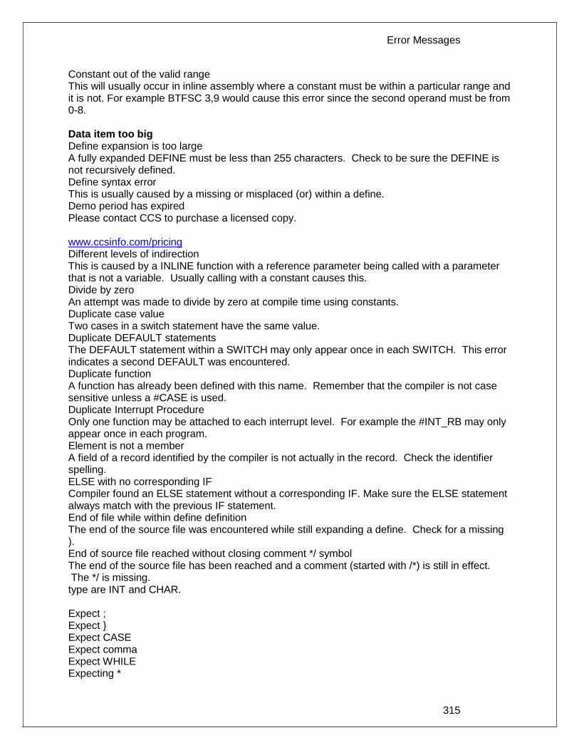
Error Messages
315
Constant out of the valid range This will usually occur in inline assembly where a constant must be within a particular range and it is not. For example BTFSC 3,9 would cause this error since the second operand must be from 0-8. Data item too big Define expansion is too large A fully expanded DEFINE must be less than 255 characters. Check to be sure the DEFINE is not recursively defined. Define syntax error This is usually caused by a missing or misplaced (or) within a define. Demo period has expired Please contact CCS to purchase a licensed copy. www.ccsinfo.com/pricing Different levels of indirection This is caused by a INLINE function with a reference parameter being called with a parameter that is not a variable. Usually calling with a constant causes this. Divide by zero An attempt was made to divide by zero at compile time using constants. Duplicate case value Two cases in a switch statement have the same value. Duplicate DEFAULT statements The DEFAULT statement within a SWITCH may only appear once in each SWITCH. This error indicates a second DEFAULT was encountered. Duplicate function A function has already been defined with this name. Remember that the compiler is not case sensitive unless a #CASE is used. Duplicate Interrupt Procedure Only one function may be attached to each interrupt level. For example the #INT_RB may only appear once in each program. Element is not a member A field of a record identified by the compiler is not actually in the record. Check the identifier spelling. ELSE with no corresponding IF Compiler found an ELSE statement without a corresponding IF. Make sure the ELSE statement always match with the previous IF statement. End of file while within define definition The end of the source file was encountered while still expanding a define. Check for a missing ). End of source file reached without closing comment */ symbol The end of the source file has been reached and a comment (started with /*) is still in effect. The */ is missing. type are INT and CHAR. Expect ; Expect } Expect CASE Expect comma Expect WHILE Expecting *

PCD
316
Expecting : Expecting < Expecting = Expecting > Expecting a ( Expecting a , or ) Expecting a , or } Expecting a . Expecting a ; or , Expecting a ; or { Expecting a close paren Expecting a declaration Expecting a structure/union Expecting a variable Expecting an = Expecting a ] Expecting a { Expecting an array Expecting an identifier Expecting function name Expecting an opcode mnemonic This must be a Microchip mnemonic such as MOVLW or BTFSC. Expecting LVALUE such as a variable name or * expression This error will occur when a constant is used where a variable should be. For example 4=5; will give this error. Expecting a basic type Examples of a basic type are INT and CHAR. Expression must be a constant or simple variable The indicated expression must evaluate to a constant at compile time. For example 5*3+1 is permitted but 5*x+1 where X is a INT is not permitted. If X were a DEFINE that had a constant value then it is permitted. Expression must evaluate to a constant The indicated expression must evaluate to a constant at compile time. For example 5*3+1 is permitted but 5*x+1 where X is a INT is not permitted. If X were a DEFINE that had a constant value then it is permitted. Expression too complex This expression has generated too much code for the compiler to handle for a single expression. This is very rare but if it happens, break the expression up into smaller parts.
Too many assembly lines are being generated for a single C statement. Contact CCS to increase the internal limits. EXTERNal symbol not found EXTERNal symbol type mis-match Extra characters on preprocessor command line Characters are appearing after a preprocessor directive that do not apply to that directive. Preprocessor commands own the entire line unlike the normal C syntax. For example the following is an error: #PRAGMA DEVICE <PIC16C74> main() { int x; x=1;}

Error Messages
317
File cannot be opened Check the filename and the current path. The file could not be opened. File cannot be opened for write The operating system would not allow the compiler to create one of the output files. Make sure the file is not marked READ ONLY and that the compiler process has write privileges to the directory and file. Filename must start with " or < The correct syntax of a #include is one of the following two formats: #include "filename.ext"
#include <filename.ext>
This error indicates neither a " or < was found after #include. Filename must terminate with " or; msg:' ' The filename specified in a #include must terminate with a " if it starts with a ". It must terminate with a > if it starts with a <. Floating-point numbers not supported for this operation A floating-point number is not permitted in the operation near the error. For example, ++F where F is a float is not allowed. Function definition different from previous definition This is a mis-match between a function prototype and a function definition. Be sure that if a #INLINE or #SEPARATE are used that they appear for both the prototype and definition. These directives are treated much like a type specifier. Function used but not defined The indicated function had a prototype but was never defined in the program. Identifier is already used in this scope An attempt was made to define a new identifier that has already been defined. Illegal C character in input file A bad character is in the source file. Try deleting the line and re-typing it. Import error Improper use of a function identifier Function identifiers may only be used to call a function. An attempt was made to otherwise reference a function. A function identifier should have a ( after it. Incorrectly constructed label This may be an improperly terminated expression followed by a label. For example: x=5+
MPLAB:
Initialization of unions is not permitted Structures can be initialized with an initial value but UNIONS cannot be. Internal compiler limit reached The program is using too much of something. An internal compiler limit was reached. Contact CCS and the limit may be able to be expanded. Internal Error - Contact CCS This error indicates the compiler detected an internal inconsistency. This is not an error with the source code; although, something in the source code has triggered the internal error. This problem can usually be quickly corrected by sending the source files to CCS so the problem can be re-created and corrected. In the meantime if the error was on a particular line, look for another way to perform the same operation. The error was probably caused by the syntax of the identified statement. If the error

PCD
318
was the last line of the code, the problem was in linking. Look at the call tree for something out of the ordinary. Interrupt handler uses too much stack Too many stack locations are being used by an interrupt handler. Invalid conversion from LONG INT to INT In this case, a LONG INT cannot be converted to an INT. You can type cast the LONG INT to perform a truncation. For example: I = INT(LI);
Invalid interrupt directive Invalid parameters to built in function Built-in shift and rotate functions (such as SHIFT_LEFT) require an expression that evaluates to a constant to specify the number of bytes. Invalid Pre-Processor directive The compiler does not know the preprocessor directive. This is the identifier in one of the following two places: #xxxxx
#PRAGMA xxxxx
Invalid ORG range The end address must be greater than or equal to the start address. The range may not overlap another range. The range may not include locations 0-3. If only one address is specified it must match the start address of a previous #org. Invalid overload function Invalid type conversion Label not permitted here Library in USE not found The identifier after the USE is not one of the pre-defined libraries for the compiler. Check the spelling. Linker Error: "%s" already defined in "%s" Linker Error: ("%s' Linker Error: Canont allocate memory for the section "%s" in the module "%s", because it overlaps with other sections. Linker Error: Cannot find unique match for symbol "%s" Linker Error: Cannot open file "%s" Linker Error: COFF file "%s" is corrupt; recompile module. Linker Error: Not enough memory in the target to reallocate the section "%s" in the module "%s". Linker Error: Section "%s" is found in the modules "%s" and "%s" with different section types. Linker Error: Unknown error, contact CCS support. Linker Error: Unresolved external symbol "%s" inside the module "%s". Linker option no compatible with prior options. Linker Warning: Section "%s" in module "%s" is declared as shared but there is no shared memory in the target chip. The shared flag is ignored. Linker option not compatible with prior options Conflicting linker options are specified. For example using both the EXCEPT= and ONLY= options in the same directive is not legal. LVALUE required This error will occur when a constant is used where a variable should be. For example 4=5; will give this error. Macro identifier requires parameters

Error Messages
319
A #DEFINE identifier is being used but no parameters were specified, as required. For example: #define min(x,y) ((x<y)?x:y)
When called MIN must have a (--,--) after it such as: r=min(value, 6);
Macro is defined recursively A C macro has been defined in such a way as to cause a recursive call to itself. Missing #ENDIF A #IF was found without a corresponding #ENDIF. Missing or invalid .CRG file The user registration file(s) are not part of the download software. In order for the software to run the files must be in the same directory as the .EXE files. These files are on the original diskette, CD ROM or e-mail in a non-compressed format. You need only copy them to the .EXE directory. There is one .REG file for each compiler (PCB.REG, PCM.REG and PCH.REG). More info: Must have a #USE DELAY before this #USE Must have a #USE DELAY before a #USE RS232 The RS232 library uses the DELAY library. You must have a #USE DELAY before you can do a #USE RS232. No errors The program has successfully compiled and all requested output files have been created. No MAIN() function found All programs are required to have one function with the name main(). No overload function matches No valid assignment made to function pointer Not enough RAM for all variables The program requires more RAM than is available. The symbol map shows variables allocated. The call tree shows the RAM used by each function. Additional RAM usage can be obtained by breaking larger functions into smaller ones and splitting the RAM between them. For example, a function A may perform a series of operations and have 20 local variables declared. Upon analysis, it may be determined that there are two main parts to the calculations and many variables are not shared between the parts. A function B may be defined with 7 local variables and a function C may be defined with 7 local variables. Function A now calls B and C and combines the results and now may only need 6 variables. The savings are accomplished because B and C are not executing at the same time and the same real memory locations will be used for their 6 variables (just not at the same time). The compiler will allocate only 13 locations for the group of functions A, B, C where 20 were required before to perform the same operation. Number of bits is out of range For a count of bits, such as in a structure definition, this must be 1-8. For a bit number specification, such as in the #BIT, the number must be 0-7. Only integers are supported for this operation Option invalid Out of ROM, A segment or the program is too large

PCD
320
A function and all of the INLINE functions it calls must fit into one segment (a hardware code page). For example, on the PIC16 chip a code page is 512 instructions. If a program has only one function and that function is 600 instructions long, you will get this error even though the chip has plenty of ROM left. The function needs to be split into at least two smaller functions. Even after this is done, this error may occur since the new function may be only called once and the linker might automatically INLINE it. This is easily determined by reviewing the call tree. If this error is caused by too many functions being automatically INLINED by the linker, simply add a #SEPARATE before a function to force the function to be SEPARATE. Separate functions can be allocated on any page that has room. The best way to understand the cause of this error is to review the call tree. Parameters must be located in RAM Parameters not permitted An identifier that is not a function or preprocessor macro can not have a ' ( ' after it. Pointers to bits are not permitted Addresses cannot be created to bits. For example, &X is not permitted if X is a SHORT INT. Previous identifier must be a pointer A -> may only be used after a pointer to a structure. It cannot be used on a structure itself or other kind of variable. Printf format type is invalid An unknown character is after the % in a printf. Check the printf reference for valid formats. Printf format (%) invalid A bad format combination was used. For example, %lc. Printf variable count (%) does not match actual count The number of % format indicators in the printf does not match the actual number of variables that follow. Remember in order to print a single %, you must use %%. Recursion not permitted The linker will not allow recursive function calls. A function may not call itself and it may not call any other function that will eventually re-call it. Recursively defined structures not permitted A structure may not contain an instance of itself. Reference arrays are not permitted A reference parameter may not refer to an array. Return not allowed in void function A return statement may not have a value if the function is void. RTOS call only allowed inside task functions Selected part does not have ICD debug capability STDOUT not defined (may be missing #RS 232) An attempt was made to use a I/O function such as printf when no default I/O stream has been established. Add a #USE RS232 to define a I/O stream. Stream must be a constant in the valid range I/O functions like fputc, fgetc require a stream identifier that was defined in a #USE RS232. This identifier must appear exactly as it does when it was defined. Be sure it has not been redefined with a #define. String too long Structure field name required A structure is being used in a place where a field of the structure must appear. Change to the form s.f where s is the structure name and f is a field name.

Error Messages
321
Structures and UNIONS cannot be parameters (use * or &) A structure may not be passed by value. Pass a pointer to the structure using &. Subscript out of range A subscript to a RAM array must be at least 1 and not more than 128 elements. Note that large arrays might not fit in a bank. ROM arrays may not occupy more than 256 locations. This linker function is not available in this compiler version. Some linker functions are only available if the PCW or PCWH product is installed. This type cannot be qualified with this qualifier Check the qualifiers. Be sure to look on previous lines. An example of this error is: VOID X;
Too many array subscripts Arrays are limited to 5 dimensions. Too many constant structures to fit into available space Available space depends on the chip. Some chips only allow constant structures in certain places. Look at the last calling tree to evaluate space usage. Constant structures will appear as functions with a @CONST at the beginning of the name. Too many elements in an ENUM A max of 256 elements are allowed in an ENUM. Too many fast interrupt handlers have been defined Too many fast interrupt handlers have been identified Too many nested #INCLUDEs No more than 10 include files may be open at a time. Too many parameters More parameters have been given to a function than the function was defined with. Too many subscripts More subscripts have been given to an array than the array was defined with. Type is not defined The specified type is used but not defined in the program. Check the spelling. Type specification not valid for a function This function has a type specifier that is not meaningful to a function. Undefined identifier Undefined label that was used in a GOTO There was a GOTO LABEL but LABEL was never encountered within the required scope. A GOTO cannot jump outside a function. Unknown device type A #DEVICE contained an unknown device. The center letters of a device are always C regardless of the actual part in use. For example, use PIC16C74 not PIC16RC74. Be sure the correct compiler is being used for the indicated device. See #DEVICE for more information. Unknown keyword in #FUSES Check the keyword spelling against the description under #FUSES. Unknown linker keyword The keyword used in a linker directive is not understood. Unknown type The specified type is used but not defined in the program. Check the spelling. User aborted compilation USE parameter invalid One of the parameters to a USE library is not valid for the current environment.

PCD
322
USE parameter value is out of range One of the values for a parameter to the USE library is not valid for the current environment. Variable never used Variable of this data type is never greater than this constant
323
COMPILER WARNING MESSAGES
Compiler Warning Messages
#error/warning Assignment inside relational expression Although legal it is a common error to do something like if(a=b) when it was intended to do if(a==b). Assignment to enum is not of the correct type. This warning indicates there may be such a typo in this line: Assignment to enum is not of the correct type If a variable is declared as a ENUM it is best to assign to the variables only elements of the enum. For example: enum colors {RED,GREEN,BLUE} color;
...
color = GREEN; // OK
color = 1; // Warning 209
color = (colors)1; //OK
Code has no effect The compiler can not discern any effect this source code could have on the generated code. Some examples: 1;
a==b;
1,2,3;
Condition always FALSE This error when it has been determined at compile time that a relational expression will never be true. For example: int x;
if( x>>9 )
Condition always TRUE This error when it has been determined at compile time that a relational expression will never be false. For example: #define PIN_A1 41
...
if( PIN_A1 ) // Intended was: if( input(PIN_A1) )
Function not void and does not return a value Functions that are declared as returning a value should have a return statement with a value to be returned. Be aware that in C only functions declared VOID are not intended to return a value. If nothing is specified as a function return value "int" is assumed. Duplicate #define The identifier in the #define has already been used in a previous #define. To redefine an identifier use #UNDEF first. To prevent defines that may be included from multiple source do something like:
#ifndef ID
#define ID text
#endif
Feature not supported
PCD
324
Function never called Function not void and does not return a value. Info: Interrupt level changed Interrupts disabled during call to prevent re-entrancy. Linker Warning: "%s" already defined in object "%s"; second definition ignored. Linker Warning: Address and size of section "%s" in module "%s" exceeds maximum range for this processor. The section will be ignored. Linker Warning: The module "%s" doesn't have a valid chip id. The module will be considered for the target chip "%s". Linker Warning: The target chip "%s" of the imported module "%s" doesn't match the target chip "%s" of the source. Linker Warning: Unsupported relocation type in module "%s". Memory not available at requested location. Operator precedence rules may not be as intended, use() to clarify Some combinations of operators are confusing to some programmers. This warning is issued for expressions where adding() would help to clarify the meaning. For example: if( x << n + 1 )
would be more universally understood when expressed: if( x << (n + 1) )
Option may be wrong Structure passed by value Structures are usually passed by reference to a function. This warning is generated if the structure is being passed by value. This warning is not generated if the structure is less than 5 bytes. For example: void myfunct( mystruct s1 ) // Pass by value - Warning
myfunct( s2 );
void myfunct( mystruct * s1 ) // Pass by reference - OK
myfunct( &s2 );
void myfunct( mystruct & s1 ) // Pass by reference - OK
myfunct( s2 );
Undefined identifier The specified identifier is being used but has never been defined. Check the spelling. Unprotected call in a #INT_GLOBAL The interrupt function defined as #INT_GLOBAL is intended to be assembly language or very simple C code. This error indicates the linker detected code that violated the standard memory allocation scheme. This may be caused when a C function is called from a #INT_GLOBAL interrupt handler. Unreachable code Code included in the program is never executed. For example: if(n==5)
goto do5;
goto exit;
if(n==20) // No way to get to this line
return;
Unsigned variable is never less than zero

Compiler Warning Messages
325
Unsigned variables are never less than 0. This warning indicates an attempt to check to see if an unsigned variable is negative. For example the following will not work as intended: int i;
for(i=10; i>=0; i--)
Variable assignment never used. Variable of this data type is never greater than this constant A variable is being compared to a constant. The maximum value of the variable could never be larger than the constant. For example the following could never be true: int x; // 8 bits, 0-255
if ( x>300)
Variable never used A variable has been declared and never referenced in the code.
Variable used before assignment is made.

326
COMMON QUESTIONS & ANSWERS
How are type conversions handled?
The compiler provides automatic type conversions when an assignment is performed. Some information may be lost if the destination can not properly represent the source. For example: int8var = int16var; Causes the top byte of int16var to be lost. Assigning a smaller signed expression to a larger signed variable will result in the sign being maintained. For example, a signed 8 bit int that is -1 when assigned to a 16 bit signed variable is still -1. Signed numbers that are negative when assigned to a unsigned number will cause the 2's complement value to be assigned. For example, assigning -1 to a int8 will result in the int8 being 255. In this case the sign bit is not extended (conversion to unsigned is done before conversion to more bits). This means the -1 assigned to a 16 bit unsigned is still 255. Likewise assigning a large unsigned number to a signed variable of the same size or smaller will result in the value being distorted. For example, assigning 255 to a signed int8 will result in -1. The above assignment rules also apply to parameters passed to functions. When a binary operator has operands of differing types then the lower order operand is converted (using the above rules) to the higher. The order is as follows:
Float Signed 32 bit Unsigned 32 bit Signed 16 bit Unsigned 16 bit Signed 8 bit Unsigned 8 bit 1 bit
The result is then the same as the operands. Each operator in an expression is evaluated independently. For example: i32 = i16 - (i8 + i8) The + operator is 8 bit, the result is converted to 16 bit after the addition and the - is 16 bit, that result is converted to 32 bit and the assignment is done. Note that if i8 is 200 and i16 is 400 then the result in i32 is 256. (200 plus 200 is 144 with a 8 bit +) Explicit conversion may be done at any point with (type) inserted before the expression to be converted. For example in the above the perhaps desired effect may be achieved by doing: i32 = i16 - ((long)i8 + i8) In this case the first i8 is converted to 16 bit, then the add is a 16 bit add and the second i8 is forced to 16 bit.

Common Questions & Answers
327
A common C programming error is to do something like: i16 = i8 * 100; When the intent was: i16 = (long) i8 * 100; Remember that with unsigned ints (the default for this compiler) the values are never negative. For example 2-4 is 254 (in 8 bit). This means the following is an endless loop since i is never less than 0: int i; for( i=100; i>=0; i--)
How can a constant data table be placed in ROM?
The compiler has support for placing any data structure into the device ROM as a constant read-only element. Since the ROM and RAM data paths are separate in the PIC® , there are restrictions on how the data is accessed. For example, to place a 10 element BYTE array in ROM use: BYTE CONST TABLE [10]= {9,8,7,6,5,4,3,2,1,0};
and to access the table use: x = TABLE [i];
OR x = TABLE [5];
BUT NOT ptr = &TABLE [i];
In this case, a pointer to the table cannot be constructed. Similar constructs using CONST may be used with any data type including structures, longs and floats. Note that in the implementation of the above table, a function call is made when a table is accessed with a subscript that cannot be evaluated at compile time.
How can I use two or more RS-232 ports on one PIC®?
The #USE RS232 (and I2C for that matter) is in effect for GETC, PUTC, PRINTF and KBHIT functions encountered until another #USE RS232 is found. The #USE RS232 is not an executable line. It works much like a #DEFINE. The following is an example program to read from one RS-232 port (A) and echo the data to both the first RS-232 port (A) and a second RS-232 port (B).

PCD
328
#USE RS232(BAUD=9600, XMIT=PIN_B0, RCV=PIN_B1)
void put_to_a( char c ) {
put(c);
}
char get_from_a( ) {
return(getc()); }
#USE RS232(BAUD=9600, XMIT=PIN_B2,RCV=PIN_B3)
void put_to_b( char b ) {
putc(c);
}
main() {
char c;
put_to_a("Online\n\r");
put_to_b("Online\n\r");
while(TRUE) {
c=get_from_a();
put_to_b(c);
put_to_a(c);
}
}
The following will do the same thing but is more readable and is the recommended method:
#USE RS232(BAUD=9600, XMIT=PIN_B0, RCV=PIN_B1, STREAM=COM_A)
#USE RS232(BAUD=9600, XMIT=PIN_B2, RCV=PIN_B3, STREAM=COM_B)
main() {
char c;
fprintf(COM_A,"Online\n\r");
fprintf(COM_B,"Online\n\r");
while(TRUE) {
c = fgetc(COM_A);
fputc(c, COM_A);
fputc(c, COM_B);
}
}
How can the RB interrupt be used to detect a button press?
The RB interrupt will happen when there is any change (input or output) on pins B4-B7. There is only one interrupt and the PIC® does not tell you which pin changed. The programmer must determine the change based on the previously known value of the port. Furthermore, a single button press may cause several interrupts due to bounce in the switch. A debounce algorithm will need to be used. The following is a simple example: #int_rb
rb_isr() {
byte changes;
changes = last_b ^ port_b;
last_b = port_b;
if (bit_test(changes,4 )&& !bit_test(last_b,4)){
//b4 went low
}
if (bit_test(changes,5)&& !bit_test (last_b,5)){
//b5 went low

Common Questions & Answers
329
}
.
.
.
delay_ms (100); //debounce
}
The delay=ms (100) is a quick and dirty debounce. In general, you will not want to sit in an ISR for 100 MS to allow the switch to debounce. A more elegant solution is to set a timer on the first interrupt and wait until the timer overflows. Do not process further changes on the pin.
How do I directly read/write to internal registers?
A hardware register may be mapped to a C variable to allow direct read and write capability to the register. The following is an example using the TIMER0 register: #BYTE timer 0 = 0x 01
timer0= 128; //set timer0 to 128
while (timer 0 ! = 200); // wait for timer0 to reach 200
Bits in registers may also be mapped as follows: #BIT T 0 IF = 0x 0B.2
.
.
.
while (!T 0 IF); //wait for timer0 interrupt
Registers may be indirectly addressed as shown in the following example: printf ("enter address:");
a = gethex ();
printf ("\r\n value is %x\r\n", *a);
The compiler has a large set of built-in functions that will allow one to perform the most common tasks with C function calls. When possible, it is best to use the built-in functions rather than directly write to registers. Register locations change between chips and some register operations require a specific algorithm to be performed when a register value is changed. The compiler also takes into account known chip errata in the implementation of the built-in functions. For example, it is better to do set_tris_ A (0); rather than *0x 85 =0;
How do I do a printf to a string?
The following is an example of how to direct the output of a printf to a string. We used the \f to indicate the start of the string. This example shows how to put a floating point number in a string. main() {
char string[20];
float f;
f=12.345;
sprintf(string,"\f%6.3f",f);
}
PCD
330
How do I get getc() to timeout after a specified time?
GETC will always wait for a character to become available unless a timeout time is specified in the #use rs232(). The following is an example of how to setup the PIC to timeout when waiting for an RS232 character. #include <18F4520.h>
#fuses HS,NOWDT
#use delay(clock=20MHz)
#use rs232(UART1,baud=9600,timeout=500) //timeout = 500 milliseconds, 1/2
second
void main()
{
char c;
while(TRUE)
{
c=getc(); //if getc() timeouts 0 is returned to c
//otherwise receive character is returned to c
if(c) //if not zero echo character back
putc(c);
//user to do code
output_toggle(PIN_A5);
}
}
How do I make a pointer to a function?
The compiler does not permit pointers to functions so that the compiler can know at compile time the complete call tree. This is used to allocate memory for full RAM re-use. Functions that could not be in execution at the same time will use the same RAM locations. In addition since there is no data stack in the PIC®, function parameters are passed in a special way that requires knowledge at compile time of what function is being called. Calling a function via a pointer will prevent knowing both of these things at compile time. Users sometimes will want function pointers to create a state machine. The following is an example of how to do this without pointers: enum tasks {taskA, taskB, taskC};
run_task(tasks task_to_run) {
switch(task_to_run) {
case taskA : taskA_main(); break;
case taskB : taskB_main(); break;
case taskC : taskC_main(); break;
}
}
How do I put a NOP at location 0 for the ICD?
The CCS compilers are fully compatible with Microchips ICD debugger using MPLAB. In order to prepare a program for ICD debugging (NOP at location 0 and so on) you need to add a #DEVICE ICD=TRUE after your normal #DEVICE.

Common Questions & Answers
331
For example: #INCLUDE <16F877.h>
#DEVICE ICD=TRUE
How do I wait only a specified time for a button press?
The following is an example of how to wait only a specific time for a button press. #define PUSH_BUTTON PIN_A4
int1 timeout_error;
int1 timed_get_button_press(void){
int16 timeout;
timeout_error=FALSE;
timeout=0;
while(input(PUSH_BUTTON) && (++timeout<50000)) // 1/2 second
delay_us(10);
if(!input(PUSH_BUTTON))
return(TRUE); //button pressed
else{
timeout_error=TRUE;
return(FALSE); //button not pressed timeout occurred
}
}
How do I write variables to EEPROM that are not a byte?
The following is an example of how to read and write a floating point number from/to EEPROM. The same concept may be used for structures, arrays or any other type.
n is an offset into the EEPROM. For floats you must increment it by 4. For example, if the first float is at 0, the second one should be at 4, and the third at 8.
WRITE_FLOAT_EXT_EEPROM( long int n, float data) {
int i;
for (i = 0; i < 4 ; i++)
write_ ext_ eeprom(i + n, *(((int 8 *)&data + i) ) ;
}
float READ_FLOAT_EXT_EEPROM( long int n) {
int i;
float data;
for (i = 0; i < 4; i++)
*(((int 8 *)&data) + i) = read_ ext_ eeprom(i + n);
return(data);
}
How does one map a variable to an I/O port?
Two methods are as follows:

PCD
332
#byte PORTB = 6 //Just an example, check the
#define ALL_OUT 0 //DATA sheet for the correct
#define ALL_IN 0xff //address for your chip
main() {
int i;
set_tris_b(ALL_OUT);
PORTB = 0;// Set all pins low
for(i=0;i<=127;++i) // Quickly count from 0 to 127
PORTB=i; // on the I/O port pin
set_tris_b(ALL_IN);
i = PORTB; // i now contains the portb value.
}
Remember when using the #BYTE, the created variable is treated like memory. You must maintain the tri-state control registers yourself via the SET_TRIS_X function. Following is an example of placing a structure on an I/O port: struct port_b_layout
{int data : 4;
int rw : 1;
int cd : 1;
int enable : 1;
int reset : 1; };
struct port_b_layout port_b;
#byte port_b = 6
struct port_b_layout const INIT_1 = {0, 1,1, 1,1 };
struct port_b_layout const INIT_2 = {3, 1,1, 1,0 };
struct port_b_layout const INIT_3 = {0, 0,0, 0,0 };
struct port_b_layout const FOR_SEND = {0,0,0, 0,0 };
// All outputs
struct port_b_layout const FOR_READ = {15,0,0, 0,0 };
// Data is an input
main() {
int x;
set_tris_b((int)FOR_SEND); // The constant
// structure is
// treated like
// a byte and
// is used to
// set the data
// direction
port_b = INIT_1;
delay_us(25);
port_b = INIT_2; // These constant structures delay_us(25);
// are used to set all fields
port_b = INIT_3; // on the port with a single
// command
set_tris_b((int)FOR_READ);
port_b.rw=0;
// Here the individual
port_b.cd=1; // fields are accessed
port_b.enable=0; // independently.
x = port_b.data;
Common Questions & Answers
333
port_b.enable=0
}
How does the compiler determine TRUE and FALSE on expressions?
When relational expressions are assigned to variables, the result is always 0 or 1. For example: bytevar = 5>0; //bytevar will be 1
bytevar = 0>5; //bytevar will be 0
The same is true when relational operators are used in expressions. For example: bytevar = (x>y)*4;
is the same as: if( x>y )
bytevar=4;
else
bytevar=0;
SHORT INTs (bit variables) are treated the same as relational expressions. They evaluate to 0 or 1. When expressions are converted to relational expressions or SHORT INTs, the result will be FALSE (or 0) when the expression is 0, otherwise the result is TRUE (or 1). For example: bytevar = 54;
bitvar = bytevar; //bitvar will be 1 (bytevar ! = O)
if(bytevar) //will be TRUE
bytevar = 0;
bitvar = bytevar; //bitvar will be 0
How does the PIC® connect to a PC?
A level converter should be used to convert the TTL (0-5V_ levels that the PIC® operates with to the RS-232 voltages (+/- 3-12V) used by the PIC®. The following is a popular configuration using the MAX232 chip as a level converter.

PCD
334
How does the PIC® connect to an I2C device?
Two I/O lines are required for I2C. Both lines must have pullup registers. Often the I2C device will have a H/W selectable address. The address set must match the address in S/W. The example programs all assume the selectable address lines are grounded.
How much time do math operations take?
Unsigned 8 bit operations are quite fast and floating point is very slow. If possible consider fixed point instead of floating point. For example instead of "float cost_in_dollars;" do "long cost_in_cents;". For trig formulas consider a lookup table instead of real time calculations (see EX_SINE.C for an example). The following are some rough times on a 14-bit PIC®. Note times will vary depending on memory banks used. 20 mhz PIC16
int8 [us] int16 [us] int32 [us]
float [us]

Common Questions & Answers
335
+ 0.6 1.4 3 111.
- 0.6 1.4 3 113.
* 11.1 47.2 132 178.
/ 23.2 70.8 239.2 330.
exp() * * * 1697.3
ln() * * * 2017.7
sin() * * * 2184.5
40 mhz PIC18
int8 [us] int16 [us] int32 [us] float [us]
+ 0.3 0.4 0.6 51.3
- 0.3 0.4 0.6 52.3
* 0.4 3.2 22.2 35.8
/ 11.3 32 106.6 144.9
exp() * * * 510.4
ln() * * * 644.8
sin() * * * 698.7
Instead of 800, the compiler calls 0. Why?
The PIC® ROM address field in opcodes is 8-10 Bits depending on the chip and specific opcode. The rest of the address bits come from other sources. For example, on the 174 chip to call address 800 from code in the first page you will see: BSF 0A,3
CALL 0
The call 0 is actually 800H since Bit 11 of the address (Bit 3 of PCLATH, Reg 0A) has been set.
Instead of A0, the compiler is using register 20. Why?
The PIC® RAM address field in opcodes is 5-7 bits long, depending on the chip. The rest of the address field comes from the status register. For example, on the 74 chip to load A0 into W you will see: BSF 3,5
MOVFW 20
Note that the BSF may not be immediately before the access since the compiler optimizes out the redundant bank switches.
What can be done about an OUT OF RAM error?

PCD
336
The compiler makes every effort to optimize usage of RAM. Understanding the RAM allocation can be a help in designing the program structure. The best re-use of RAM is accomplished when local variables are used with lots of functions. RAM is re-used between functions not active at the same time. See the NOT ENOUGH RAM error message in this manual for a more detailed example. RAM is also used for expression evaluation when the expression is complex. The more complex the expression, the more scratch RAM locations the compiler will need to allocate to that expression. The RAM allocated is reserved during the execution of the entire function but may be re-used between expressions within the function. The total RAM required for a function is the sum of the parameters, the local variables and the largest number of scratch locations required for any expression within the function. The RAM required for a function is shown in the call tree after the RAM=. The RAM stays used when the function calls another function and new RAM is allocated for the new function. However when a function RETURNS the RAM may be re-used by another function called by the parent. Sequential calls to functions each with their own local variables is very efficient use of RAM as opposed to a large function with local variables declared for the entire process at once. Be sure to use SHORT INT (1 bit) variables whenever possible for flags and other boolean variables. The compiler can pack eight such variables into one byte location. The compiler does this automatically whenever you use SHORT INT. The code size and ROM size will be smaller. Finally, consider an external memory device to hold data not required frequently. An external 8 pin EEPROM or SRAM can be connected to the PIC® with just 2 wires and provide a great deal of additional storage capability. The compiler package includes example drivers for these devices. The primary drawback is a slower access time to read and write the data. The SRAM will have fast read and write with memory being lost when power fails. The EEPROM will have a very long write cycle, but can retain the data when power is lost.
What is an easy way for two or more PICs® to communicate?
There are two example programs (EX_PBUSM.C and EX_PBUSR.C) that show how to use a simple one-wire interface to transfer data between PICs®. Slower data can use pin B0 and the EXT interrupt. The built-in UART may be used for high speed transfers. An RS232 driver chip may be used for long distance operations. The RS485 as well as the high speed UART require 2 pins and minor software changes. The following are some hardware configurations.

Common Questions & Answers
337
What is an easy way for two or more PICs® to communicate?
There are two example programs (EX_PBUSM.C and EX_PBUSR.C) that show how to use a simple one-wire interface to transfer data between PICs®. Slower data can use pin B0 and the EXT interrupt. The built-in UART may be used for high speed transfers. An RS232 driver chip may be used for long distance operations. The RS485 as well as the high speed UART require 2 pins and minor software changes. The following are some hardware configurations.

PCD
338
What is the format of floating point numbers?
CCS uses the same format Microchip uses in the 14000 calibration constants. PCW users have a utility Numeric Converter that will provide easy conversion to/from decimal, hex and float in a small window in the Windows IDE. See EX_FLOAT.C for a good example of using floats or float types variables. The format is as follows:
Example Number 0 00 00 00 00 1 7F 00 00 00 -1 7F 80 00 00 10 82 20 00 00 100 85 48 00 00 123.45 85 76 E6 66 123.45E20 C8 27 4E 53 123.45 E-20 43 36 2E 17

Common Questions & Answers
339
Why does the .LST file look out of order?
The list file is produced to show the assembly code created for the C source code. Each C source line has the corresponding assembly lines under it to show the compiler’s work. The
following three special cases make the .LST file look strange to the first time viewer. Understanding how the compiler is working in these special cases will make the .LST file appear quite normal and very useful. 1. Stray code near the top of the program is sometimes under what looks like a non-executable source line. Some of the code generated by the compiler does not correspond to any particular source line. The compiler will put this code either near the top of the program or sometimes under a #USE that caused subroutines to be generated. 2. The addresses are out of order. The compiler will create the .LST file in the order of the C source code. The linker has re-arranged the code to properly fit the functions into the best code pages and the best half of a code page. The resulting code is not in source order. Whenever the compiler has a discontinuity in the .LST file, it will put a * line in the file. This is most often seen between functions and in places where INLINE functions are called. In the case of an INLINE function, the addresses will continue in order up where the source for the INLINE function is located. 3. The compiler has gone insane and generated the same instruction over and over. For example:
...........A=0;
03F: CLRF 15
*
46:CLRF 15
*
051: CLRF 15
*
113: CLRF 15
This effect is seen when the function is an INLINE function and is called from more than one place. In the above case, the A=0 line is in an INLINE function called in four places. Each place it is called from gets a new copy of the code. Each instance of the code is shown along with the original source line, and the result may look unusual until the addresses and the * are noticed.
Why does the compiler show less RAM than there really is?
Some devices make part of the RAM much more ineffective to access than the standard RAM. In particular, the 509, 57, 66, 67,76 and 77 devices have this problem. By default, the compiler will not automatically allocate variables to the problem RAM and, therefore, the RAM available will show a number smaller than expected.

PCD
340
There are three ways to use this RAM: 1. Use #BYTE or #BIT to allocate a variable in this RAM. Do NOT create a pointer to these variables. Example:
#BYTE counter=0x30
2. Use Read_Bank and Write_Bank to access the RAM like an array. This works well if you need to allocate an array in this RAM. Example:
For(i=0;i<15;i++)
Write_Bank(1,i,getc());
For(i=0;i<=15;i++)
PUTC(Read_Bank(1,i));
3. You can switch to larger pointers for full RAM access (this takes more ROM). In PCB add *=8 to the #device and in PCM/PCH add *=16 to the #device. Example:
#DEVICE PIC16C77 *=16
or
#include <16C77.h>
#device *=16
Why does the compiler use the obsolete TRIS?
The use of TRIS causes concern for some users. The Microchip data sheets recommend not using TRIS instructions for upward compatibility. If you had existing ASM code and it used TRIS then it would be more difficult to port to a new Microchip part without TRIS. C does not have this problem, however; the compiler has a device database that indicates specific characteristics for every part. This includes information on whether the part has a TRIS and a list of known problems with the part. The latter question is answered by looking at the device errata. CCS makes every attempt to add new devices and device revisions as the data and errata sheets become available. PCW users can edit the device database. If the use of TRIS is a concern, simply change the database entry for your part and the compiler will not use it.
Why is the RS-232 not working right?
1. The PIC® is Sending Garbage Characters.
A. Check the clock on the target for accuracy. Crystals are usually not a problem but RC oscillators can cause trouble with RS-232. Make sure the #USE DELAY matches the actual clock frequency. B. Make sure the PC (or other host) has the correct baud and parity setting.

Common Questions & Answers
341
C. Check the level conversion. When using a driver/receiver chip, such as the MAX 232, do not use INVERT when making direct connections with resistors and/or diodes. You probably need the INVERT option in the #USE RS232. D. Remember that PUTC(6) will send an ASCII 6 to the PC and this may not be a visible character. PUTC('A') will output a visible character A.
2. The PIC® is Receiving Garbage Characters.
A. Check all of the above. 3. Nothing is Being Sent.
A. Make sure that the tri-state registers are correct. The mode (standard, fast, fixed) used will be whatever the mode is when the #USE RS232 is encountered. Staying with the default STANDARD mode is safest. B. Use the following main() for testing:
main() {
while(TRUE)
putc('U');
}
Check the XMIT pin for activity with a logic probe, scope or whatever you can. If you can look at it with a scope, check the bit time (it should be 1/BAUD). Check again after the level converter.
4. Nothing is being received.
First be sure the PIC® can send data. Use the following main() for testing:
main() {
printf("start");
while(TRUE)
putc( getc()+1 );
}
When connected to a PC typing A should show B echoed back. If nothing is seen coming back (except the initial "Start"), check the RCV pin on the PIC® with a logic probe. You should see a HIGH state and when a key is pressed at the PC, a pulse to low. Trace back to find out where it is lost.
5. The PIC® is always receiving data via RS-232 even when none is being sent.
A. Check that the INVERT option in the USE RS232 is right for your level converter. If the RCV pin is HIGH when no data is being sent, you should NOT use INVERT. If the pin is low when no data is being sent, you need to use INVERT. B. Check that the pin is stable at HIGH or LOW in accordance with A above when no data is being sent.

PCD
342
C. When using PORT A with a device that supports the SETUP_ADC_PORTS function make sure the port is set to digital inputs. This is not the default. The same is true for devices with a comparator on PORT A.
6. Compiler reports INVALID BAUD RATE.
A. When using a software RS232 (no built-in UART), the clock cannot be really slow when fast baud rates are used and cannot be really fast with slow baud rates. Experiment with the clock/baud rate values to find your limits. B. When using the built-in UART, the requested baud rate must be within 3% of a rate that can be achieved for no error to occur. Some parts have internal bugs with BRGH set to 1 and the compiler will not use this unless you specify BRGH1OK in the #USE RS232 directive.

343
EXAMPLE PROGRAMS
EXAMPLE PROGRAMS
A large number of example programs are included with the software. The following is a list of many of the programs and some of the key programs are re-printed on the following pages. Most programs will work with any chip by just changing the #INCLUDE line that includes the device information. All of the following programs have wiring instructions at the beginning of the code in a comment header. The SIOW.EXE program included in the program directory may be used to demonstrate the example programs. This program will use a PC COM port to communicate with the target. Generic header files are included for the standard PIC® parts. These files are in the DEVICES directory. The pins of the chip are defined in these files in the form PIN_B2. It is recommended that for a given project, the file is copied to a project header file and the PIN_xx defines be changed to match the actual hardware. For example; LCDRW (matching the mnemonic on the schematic). Use the generic include files by placing the following in your main .C file: #include <16C74.H> LIST OF COMPLETE EXAMPLE PROGRAMS (in the EXAMPLES directory) EX_14KAD.C An analog to digital program with calibration for the PIC14000 EX_1920.C Uses a Dallas DS1920 button to read temperature EX_8PIN.C Demonstrates the use of 8 pin PICs with their special I/O requirements EX_92LCD.C Uses a PIC16C92x chip to directly drive LCD glass EX_AD12.C Shows how to use an external 12 bit A/D converter EX_ADMM.C A/D Conversion example showing min and max analog readings EX_ADMM10.C Similar to ex_admm.c, but this uses 10bit A/D readings. EX_ADMM_STATS.C Similar to ex_admm.c, but this uses also calculates the mean and standard deviation. EX_BOOTLOAD.C A stand-alone application that needs to be loaded by a bootloader (see ex_bootloader.c for a bootloader).

PCD
344
EX_BOOTLOADER.C A bootloader, loads an application onto the PIC (see ex_bootload.c for an application). EX_CAN.C Receive and transmit CAN packets. EX_CHECKSUM.C Determines the checksum of the program memory, verifies it agains the checksum that was written to the USER ID location of the PIC. EX_CCP1S.C Generates a precision pulse using the PIC CCP module EX_CCPMP.C Uses the PIC CCP module to measure a pulse width EX_COMP.C Uses the analog comparator and voltage reference available on some PIC s EX_CRC.C Calculates CRC on a message showing the fast and powerful bit operations EX_CUST.C Change the nature of the compiler using special preprocessor directives EX_FIXED.C Shows fixed point numbers EX_DPOT.C Controls an external digital POT EX_DTMF.C Generates DTMF tones EX_ENCOD.C Interfaces to an optical encoder to determine direction and speed EX_EXPIO.C Uses simple logic chips to add I/O ports to the PIC EX_EXSIO.C Shows how to use a multi-port external UART chip EX_EXTEE.C Reads and writes to an external EEPROM EX_EXTDYNMEM.C Uses addressmod to create a user defined storage space, where a new qualifier is created that reads/writes to an extrenal RAM device. EX_FAT.C

Example Programs
345
An example of reading and writing to a FAT file system on an MMC/SD card. EX_FLOAT.C Shows how to use basic floating point EX_FREQC.C A 50 mhz frequency counter EX_GLCD.C Displays contents on a graphic LCD, includes shapes and text. EX_GLINT.C Shows how to define a custom global interrupt hander for fast interrupts EX_HPINT.C An example of how to use the high priority interrupts of a PIC18. EX_HUMIDITY.C How to read the humidity from a Humirel HT3223/HTF3223 Humidity module EX_ICD.C Shows a simple program for use with Microchips ICD debugger EX_INTEE.C Reads and writes to the PIC internal EEPROM EX_INTFL.C An example of how to write to the program memory of the PIC. EX_LCDKB.C Displays data to an LCD module and reads data for keypad EX_LCDTH.C Shows current, min and max temperature on an LCD EX_LED.C Drives a two digit 7 segment LED EX_LINBUS_MASTER.C An example of how to use the LINBUS mode of a PIC's EAUSART. Talks to the EX_LINBUS_SLAVE.C example. EX_LINBUS_SLAVE.C An example of how to use the LINBUS mode of a PIC's EAUSART. Talks to the EX_LINBUS_MASTER.C example. EX_LOAD.C Serial boot loader program for chips like the 16F877 EX_LOGGER.C A simple temperature data logger, uses the flash program memory for saving data

PCD
346
EX_MACRO.C Shows how powerful advanced macros can be in C EX_MALLOC.C An example of dynamic memory allocation using malloc(). EX_MCR.C An example of reading magnetic card readers. EX_MMCSD.C An example of using an MMC/SD media card as an external EEPROM. To use this card with a FAT file system, see ex_fat.c EX_MODBUS_MASTER.C An example MODBUS application, this is a master and will talk to the ex_modbus_slave.c example. EX_MODBUS_SLAVE.C An example MODBUS application, this is a slave and will talk to the ex_modbus_master.c example. EX_MOUSE.C Shows how to implement a standard PC mouse on a PIC EX_MXRAM.C Shows how to use all the RAM on parts with problem memory allocation EX_PATG.C Generates 8 square waves of different frequencies EX_PBUSM.C Generic PIC to PIC message transfer program over one wire EX_PBUSR.C Implements a PIC to PIC shared RAM over one wire EX_PBUTT.C Shows how to use the B port change interrupt to detect pushbuttons EX_PGEN.C Generates pulses with period and duty switch selectable EX_PLL.C Interfaces to an external frequency synthesizer to tune a radio EX_POWER_PWM.C How to use the enhanced PWM module of the PIC18 for motor controls. EX_PSP.C Uses the PIC PSP to implement a printer parallel to serial converter

Example Programs
347
EX_PULSE.C Measures a pulse width using timer0 EX_PWM.C Uses the PIC CCP module to generate a pulse stream EX_QSORT.C An example of using the stdlib function qsort() to sort data. Pointers to functions is used by qsort() so the user can specify their sort algorithm. EX_REACT.C Times the reaction time of a relay closing using the CCP module EX_RFID.C An example of how to read the ID from a 125kHz RFID transponder tag. EX_RMSDB.C Calculates the RMS voltage and dB level of an AC signal EX_RS485.C An application that shows a multi-node communication protocol commonly found on RS-485 busses. EX_RTC.C Sets and reads an external Real Time Clock using RS232 EX_RTCLK.C Sets and reads an external Real Time Clock using an LCD and keypad EX_RTCTIMER.C How to use the PIC's hardware timer as a real time clock. EX_RTOS_DEMO_X.C 9 examples are provided that show how to use CCS's built-in RTOS (Real Time Operating System). EX_SINE.C Generates a sine wave using a D/A converter EX_SISR.C Shows how to do RS232 serial interrupts EX_STISR.C Shows how to do RS232 transmit buffering with interrupts EX_SLAVE.C Simulates an I2C serial EEPROM showing the PIC slave mode EX_SPEED.C Calculates the speed of an external object like a model car

PCD
348
EX_SPI.C Communicates with a serial EEPROM using the H/W SPI module EX_SPI_SLAVE.C How to use the PIC's MSSP peripheral as a SPI slave. This example will talk to the ex_spi.c example. EX_SQW.C Simple Square wave generator EX_SRAM.C Reads and writes to an external serial RAM EX_STEP.C Drives a stepper motor via RS232 commands and an analog input EX_STR.C Shows how to use basic C string handling functions EX_STWT.C A stop Watch program that shows how to user a timer interrupt EX_SYNC_MASTER.C EX_SYNC_SLAVE.C An example of using the USART of the PIC in synchronous mode. The master and slave examples talk to each other. EX_TANK.C Uses trig functions to calculate the liquid in a odd shaped tank EX_TEMP.C Displays (via RS232) the temperature from a digital sensor EX_TGETC.C Demonstrates how to timeout of waiting for RS232 data EX_TONES.C Shows how to generate tones by playing "Happy Birthday" EX_TOUCH.C Reads the serial number from a Dallas touch device EX_USB_HID.C Implements a USB HID device on the PIC16C765 or an external USB chip EX_USB_SCOPE.C Implements a USB bulk mode transfer for a simple oscilloscope on an ext USB chip EX_USB_KBMOUSE.C EX_USB_KBMOUSE2.C

Example Programs
349
Examples of how to implement 2 USB HID devices on the same device, by combining a mouse and keyboard. EX_USB_SERIAL.C EX_USB_SERIAL2.C Examples of using the CDC USB class to create a virtual COM port for backwards compatability with legacy software. EX_VOICE.C Self learning text to voice program EX_WAKUP.C Shows how to put a chip into sleep mode and wake it up EX_WDT.C Shows how to use the PIC watch dog timer EX_WDT18.C Shows how to use the PIC18 watch dog timer EX_X10.C Communicates with a TW523 unit to read and send power line X10 codes EX_EXTA.C The XTEA encryption cipher is used to create an encrypted link between two PICs. LIST OF INCLUDE FILES (in the DRIVERS directory) 14KCAL.C Calibration functions for the PIC14000 A/D converter 2401.C Serial EEPROM functions 2402.C Serial EEPROM functions 2404.C Serial EEPROM functions 2408.C Serial EEPROM functions 24128.C Serial EEPROM functions 2416.C Serial EEPROM functions 24256.C Serial EEPROM functions

PCD
350
2432.C Serial EEPROM functions 2465.C Serial EEPROM functions 25160.C Serial EEPROM functions 25320.C Serial EEPROM functions 25640.C Serial EEPROM functions 25C080.C Serial EEPROM functions 68HC68R1 C Serial RAM functions 68HC68R2.C Serial RAM functions 74165.C Expanded input functions 74595.C Expanded output functions 9346.C Serial EEPROM functions 9356.C Serial EEPROM functions 9356SPI.C Serial EEPROM functions (uses H/W SPI) 9366.C Serial EEPROM functions AD7705.C A/D Converter functions AD7715.C A/D Converter functions AD8400.C Digital POT functions

Example Programs
351
ADS8320.C A/D Converter functions ASSERT.H Standard C error reporting AT25256.C Serial EEPROM functions AT29C1024.C Flash drivers for an external memory chip CRC.C CRC calculation functions CE51X.C Functions to access the 12CE51x EEPROM CE62X.C Functions to access the 12CE62x EEPROM CE67X.C Functions to access the 12CE67x EEPROM CTYPE.H Definitions for various character handling functions DS1302.C Real time clock functions DS1621.C Temperature functions DS1621M.C Temperature functions for multiple DS1621 devices on the same bus DS1631.C Temperature functions DS1624.C Temperature functions DS1868.C Digital POT functions ERRNO.H Standard C error handling for math errors FLOAT.H Standard C float constants

PCD
352
FLOATEE.C Functions to read/write floats to an EEPROM INPUT.C Functions to read strings and numbers via RS232 ISD4003.C Functions for the ISD4003 voice record/playback chip KBD.C Functions to read a keypad LCD.C LCD module functions LIMITS.H Standard C definitions for numeric limits LMX2326.C PLL functions LOADER.C A simple RS232 program loader LOCALE.H Standard C functions for local language support LTC1298.C 12 Bit A/D converter functions MATH.H Various standard trig functions MAX517.C D/A converter functions MCP3208.C A/D converter functions NJU6355.C Real time clock functions PCF8570.C Serial RAM functions PIC_USB.H Hardware layer for built-in PIC USB SC28L19X.C Driver for the Phillips external UART (4 or 8 port)

Example Programs
353
SETJMP.H Standard C functions for doing jumps outside functions STDDEF.H Standard C definitions STDIO.H Not much here - Provided for standard C compatibility STDLIB.H String to number functions STDLIBM.H Standard C memory management functions STRING.H Various standard string functions TONES.C Functions to generate tones TOUCH.C Functions to read/write to Dallas touch devices USB.H Standard USB request and token handler code USBN960X.C Functions to interface to Nationals USBN960x USB chips USB.C USB token and request handler code, Also includes usb_desc.h and usb.h X10.C Functions to read/write X10 codes
/////////////////////////////////////////////////////////////////
/// EX_SQW.C ///
/// This program displays a message over the RS-232 and ///
/// waits for any keypress to continue. The program ///
/// will then begin a 1khz square wave over I/O pin B0. ///
/// Change both delay_us to delay_ms to make the ///
/// frequency 1 hz. This will be more visible on ///
/// a LED. Configure the CCS prototype card as follows: ///
/// insert jumpers from 11 to 17, 12 to 18, and 42 to 47. ///
/////////////////////////////////////////////////////////////////
#ifdef __PCB__
#include <16C56.H>
#else
#include <16C84.H>

PCD
354
#endif
#use delay(clock=20000000)
#use rs232(baud=9600, xmit=PIN_A3, rcv=PIN_A2)
main() {
printf("Press any key to begin\n\r");
getc();
printf("1 khz signal activated\n\r");
while (TRUE) {
output_high (PIN_B0);
delay_us(500);
output_low(PIN_B0);
delay_us(500);
}
}
/////////////////////////////////////////////////////////////////
/// EX_STWT.C ///
/// This program uses the RTCC (timer0) and interrupts ///
/// to keep a real time seconds counter. A simple stop ///
/// watch function is then implemented. Configure the ///
/// CCS prototype card as follows, insert jumpers from: ///
/// 11 to 17 and 12 to 18. ///
/////////////////////////////////////////////////////////////////
#include <16C84.H>
#use delay (clock=20000000)
#use rs232(baud=9600, xmit=PIN_A3, rcv=PIN_A2_
#define INTS_PER_SECOND 76 //(20000000/(4*256*256))
byte seconds; //Number of interrupts left
//before a second has elapsed
#int_rtcc //This function is called
clock_isr() { //every time the RTCC (timer0)
//overflows (255->0)
//For this program this is apx
//76 times per second.
if(--int_count==0) {
++seconds;
int_count=INTS_PER_SECOND;
}
}
main() {
byte start;
int_count=INTS_PER_SECOND;
set_rtcc(0);
setup_counters (RTCC_INTERNAL, RTCC_DIV_256);
enable_interrupts (INT_RTCC);
enable_interrupts(GLOBAL)
do {
printf ("Press any key to begin. \n\r");

Example Programs
355
getc();
start=seconds;
printf("Press any key to stop. \n\r");
getc();
printf ("%u seconds. \n\r", seconds-start);
} while (TRUE);
}
/////////////////////////////////////////////////////////////////
/// EX_INTEE.C ///
/// This program will read and write to the ’83 or ’84 ///
/// internal EEPROM. Configure the CCS prototype card as ///
/// follows: insert jumpers from 11 to 17 and 12 to 18. ///
/////////////////////////////////////////////////////////////////
#include <16C84.H>
#use delay(clock-100000000)
#use rs232 (baud=9600, xmit=PIN_A3, rv+PIN_A2)
#include <HEX.C>
main () {
byte i,j,address, value;
do {
printf("\r\n\nEEPROM: \r\n") //Displays contents
for(i=0; i<3; ++i) { //entire EEPROM
for (j=0; j<=15; ++j) { //in hex
printf("%2x", read_eeprom(i+16+j));
}
printf("\n\r");
}
printf ("\r\nlocation to change: ");
address= gethex();
printf ("\r\nNew value: ");
value=gethex();
write_eeprom (address, value);
} while (TRUE)
}
/////////////////////////////////////////////////////////////////
/// Library for a Microchip 93C56 configured for a x8 ///
/// ///
/// org init_ext_eeprom(); Call before the other ///
/// functions are used ///
/// ///
/// write_ext_eeprom(a,d); Write the byte d to ///
/// the address a ///
/// ///
/// d=read_ext_eeprom (a); Read the byte d from ///
/// the address a. ///
/// The main program may define eeprom_select, ///

PCD
356
/// eeprom_di, eeprom_do and eeprom_clk to override ///
/// the defaults below. ///
/////////////////////////////////////////////////////////////////
#ifndef EEPROM_SELECT
#define EEPROM_SELECT PIN_B7
#define EEPROM_CLK PIN_B6
#define EEPROM_DI PIN_B5
#define EEPROM_DO PIN_B4
#endif
#define EEPROM_ADDRESS byte
#define EEPROM_SIZE 256
void init_ext_eeprom () {
byte cmd[2];
byte i;
output_low(EEPROM_DI);
output_low(EEPROM_CLK);
output_low(EEPROM_SELECT);
cmd[0]=0x80;
cmd[1]=0x9;
for (i=1; i<=4; ++i)
shift_left(cmd, 2,0);
output_high (EEPROM_SELECT);
for (i=1; i<=12; ++i) {
output_bit(EEPROM_DI, shift_left(cmd, 2,0));
output_high (EEPROM_CLK);
output_low(EEPROM_CLK);
}
output_low(EEPROM_DI);
output_low(EEPROM_SELECT);
}
void write_ext_eeprom (EEPROM_ADDRESS address, byte data) {
byte cmd[3];
byte i;
cmd[0]=data;
cmd[1]=address;
cmd[2]=0xa;
for(i=1;i<=4;++i)
shift_left(cmd,3,0);
output_high(EEPROM_SELECT);
for(i=1;i<=20;++i) {
output_bit (EEPROM_DI, shift_left (cmd,3,0));
output_high (EEPROM_CLK);
output_low(EEPROM_CLK);
}
output_low (EEPROM_DI);
output_low (EEPROM_SELECT);

Example Programs
357
delay_ms(11);
}
byte read_ext_eeprom(EEPROM_ADDRESS address) {
byte cmd[3];
byte i, data;
cmd[0]=0;
cmd[1]=address;
cmd[2]=0xc;
for(i=1;i<=4;++i)
shift_left(cmd,3,0);
output_high(EEPROM_SELECT);
for(i=1;i<=20;++i) {
output_bit (EEPROM_DI, shift_left (cmd,3,0));
output_high (EEPROM_CLK);
output_low(EEPROM_CLK);
if (i>12)
shift_left (&data, 1, input (EEPROM_DO));
}
output_low (EEPROM_SELECT);
return(data);
}
/////////////////////////////////////////////////////////////////
/// This file demonstrates how to use the real time ///
/// operating system to schedule tasks and how to use ///
/// the rtos_run function. ///
/// ///
/// this demo makes use of the PIC18F452 prototyping board ///
/////////////////////////////////////////////////////////////////
#include <18F452.h>
#use delay(clock=20000000)
#use rs232(baud=9600,xmit=PIN_C6,rcv=PIN_C7)
// this tells the compiler that the rtos functionality will be needed,
that
// timer0 will be used as the timing device, and that the minor cycle for
// all tasks will be 500 miliseconds
#use rtos(timer=0,minor_cycle=100ms)
// each function that is to be an operating system task must have the
#task
// preprocessor directive located above it.
// in this case, the task will run every second, its maximum time to run
is
// less than the minor cycle but this must be less than or equal to the
// minor cycle, and there is no need for a queue at this point, so no
// memory will be reserved.
#task(rate=1000ms,max=100ms)
// the function can be called anything that a standard function can be
called
void The_first_rtos_task ( )
{
printf("1\n\r");
}

PCD
358
#task(rate=500ms,max=100ms)
void The_second_rtos_task ( )
{
printf("\t2!\n\r");
}
#task(rate=100ms,max=100ms)
void The_third_rtos_task ( )
{
printf("\t\t3\n\r");
}
// main is still the entry point for the program
void main ( )
{
// rtos_run begins the loop which will call the task functions above at
the
// schedualed time
rtos_run ( );
}
/////////////////////////////////////////////////////////////////
/// This file demonstrates how to use the real time ///
/// operating system rtos_terminate function ///
/// ///
/// this demo makes use of the PIC18F452 prototyping board ///
/////////////////////////////////////////////////////////////////
#include <18F452.h>
#use delay(clock=20000000)
#use rs232(baud=9600,xmit=PIN_C6,rcv=PIN_C7)
#use rtos(timer=0,minor_cycle=100ms)
// a counter will be kept
int8 counter;
#task(rate=1000ms,max=100ms)
void The_first_rtos_task ( )
{
printf("1\n\r");
// if the counter has reached the desired value, the rtos will
terminate
if(++counter==5)
rtos_terminate ( );
}
#task(rate=500ms,max=100ms)
void The_second_rtos_task ( )
{
printf("\t2!\n\r");
}
#task(rate=100ms,max=100ms)
void The_third_rtos_task ( )
{
printf("\t\t3\n\r");
}
void main ( )
{
// main is the best place to initialize resources the the rtos is
dependent
// upon

Example Programs
359
counter = 0;
rtos_run ( );
// once the rtos_terminate function has been called, rtos_run will
return
// program control back to main
printf("RTOS has been terminated\n\r");
}
/////////////////////////////////////////////////////////////////
/// This file demonstrates how to use the real time ///
/// operating system rtos_enable and rtos_disable functions ///
/// ///
/// this demo makes use of the PIC18F452 prototyping board ///
/////////////////////////////////////////////////////////////////
#include <18F452.h>
#use delay(clock=20000000)
#use rs232(baud=9600,xmit=PIN_C6,rcv=PIN_C7)
#use rtos(timer=0,minor_cycle=100ms)
int8 counter;
// now that task names will be passed as parameters, it is best
// to declare function prototypes so that their are no undefined
// identifier errors from the compiler
#task(rate=1000ms,max=100ms)
void The_first_rtos_task ( );
#task(rate=500ms,max=100ms)
void The_second_rtos_task ( );
#task(rate=100ms,max=100ms)
void The_third_rtos_task ( );
void The_first_rtos_task ( ) {
printf("1\n\r");
if(counter==3)
{
// to disable a task, simply pass the task name
// into the rtos_disable function
rtos_disable(The_third_rtos_task);
}
}
void The_second_rtos_task ( ) {
printf("\t2!\n\r");
if(++counter==10) {
counter=0;
// enabling tasks is similar to disabling them
rtos_enable(The_third_rtos_task);
}
}
void The_third_rtos_task ( ) {
printf("\t\t3\n\r");
}
void main ( ) {
counter = 0;
rtos_run ( );
}

PCD
360
/////////////////////////////////////////////////////////////////
/// This file demonstrates how to use the real time /// /// operating systems messaging functions ///
/// ///
/// this demo makes use of the PIC18F452 prototyping board ///
/////////////////////////////////////////////////////////////////
#include <18F452.h>
#use delay(clock=20000000)
#use rs232(baud=9600,xmit=PIN_C6,rcv=PIN_C7)
#use rtos(timer=0,minor_cycle=100ms)
int8 count;
// each task will now be given a two byte queue
#task(rate=1000ms,max=100ms,queue=2)
void The_first_rtos_task ( );
#task(rate=500ms,max=100ms,queue=2)
void The_second_rtos_task ( );
void The_first_rtos_task ( ) {
// the function rtos_msg_poll will return the number of messages in the
// current tasks queue
// always make sure to check that their is a message or else the read
// function will hang
if(rtos_msg_poll ( )>0){
// the function rtos_msg_read, reads the first value in the queue
printf("messages recieved by task1 : %i\n\r",rtos_msg_read ( ));
// the funciton rtos_msg_send, sends the value given as the
// second parameter to the function given as the first
rtos_msg_send(The_second_rtos_task,count);
count++;
}
}
void The_second_rtos_task ( ) {
rtos_msg_send(The_first_rtos_task,count);
if(rtos_msg_poll ( )>0){
printf("messages recieved by task2 : %i\n\r",rtos_msg_read ( ));
count++;
}
}
void main ( ) {
count=0;
rtos_run();
}
/////////////////////////////////////////////////////////////////
/// This file demonstrates how to use the real time /// /// operating systems yield function ///
/// ///
/// this demo makes use of the PIC18F452 prototyping board ///
/////////////////////////////////////////////////////////////////
#include <18F452.h>
#use delay(clock=20000000)
#use rs232(baud=9600,xmit=PIN_C6,rcv=PIN_C7)
#use rtos(timer=0,minor_cycle=100ms)
#task(rate=1000ms,max=100ms,queue=2)
void The_first_rtos_task ( );
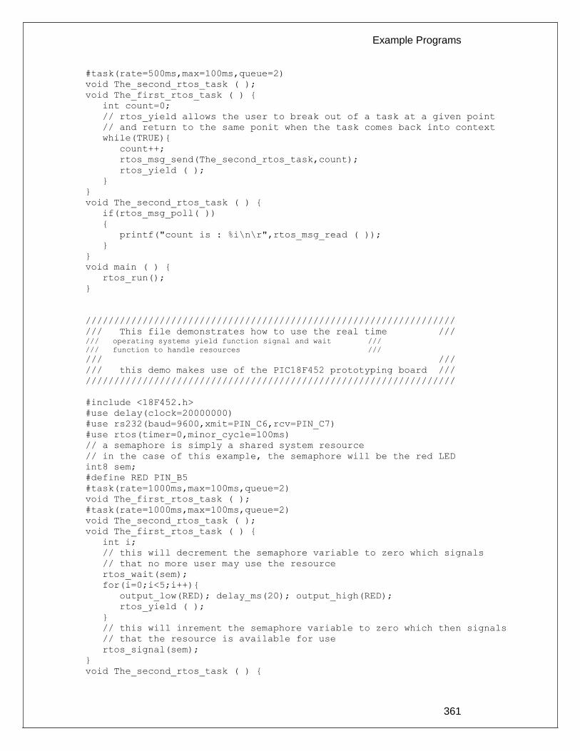
Example Programs
361
#task(rate=500ms,max=100ms,queue=2)
void The_second_rtos_task ( );
void The_first_rtos_task ( ) {
int count=0;
// rtos_yield allows the user to break out of a task at a given point
// and return to the same ponit when the task comes back into context
while(TRUE){
count++;
rtos_msg_send(The_second_rtos_task,count);
rtos_yield ( );
}
}
void The_second_rtos_task ( ) {
if(rtos_msg_poll( ))
{
printf("count is : %i\n\r",rtos_msg_read ( ));
}
}
void main ( ) {
rtos_run();
}
/////////////////////////////////////////////////////////////////
/// This file demonstrates how to use the real time /// /// operating systems yield function signal and wait ///
/// function to handle resources ///
/// ///
/// this demo makes use of the PIC18F452 prototyping board ///
/////////////////////////////////////////////////////////////////
#include <18F452.h>
#use delay(clock=20000000)
#use rs232(baud=9600,xmit=PIN_C6,rcv=PIN_C7)
#use rtos(timer=0,minor_cycle=100ms)
// a semaphore is simply a shared system resource
// in the case of this example, the semaphore will be the red LED
int8 sem;
#define RED PIN_B5
#task(rate=1000ms,max=100ms,queue=2)
void The_first_rtos_task ( );
#task(rate=1000ms,max=100ms,queue=2)
void The_second_rtos_task ( );
void The_first_rtos_task ( ) {
int i;
// this will decrement the semaphore variable to zero which signals
// that no more user may use the resource
rtos_wait(sem);
for(i=0;i<5;i++){
output_low(RED); delay_ms(20); output_high(RED);
rtos_yield ( );
}
// this will inrement the semaphore variable to zero which then signals
// that the resource is available for use
rtos_signal(sem);
}
void The_second_rtos_task ( ) {
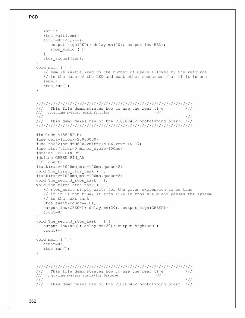
PCD
362
int i;
rtos_wait(sem);
for(i=0;i<5;i++){
output_high(RED); delay_ms(20); output_low(RED);
rtos_yield ( );
}
rtos_signal(sem);
}
void main ( ) {
// sem is initialized to the number of users allowed by the resource
// in the case of the LED and most other resources that limit is one
sem=1;
rtos_run();
}
/////////////////////////////////////////////////////////////////
/// This file demonstrates how to use the real time /// /// operating systems await function ///
/// ///
/// this demo makes use of the PIC18F452 prototyping board ///
/////////////////////////////////////////////////////////////////
#include <18F452.h>
#use delay(clock=20000000)
#use rs232(baud=9600,xmit=PIN_C6,rcv=PIN_C7)
#use rtos(timer=0,minor_cycle=100ms)
#define RED PIN_B5
#define GREEN PIN_A5
int8 count;
#task(rate=1000ms,max=100ms,queue=2)
void The_first_rtos_task ( );
#task(rate=1000ms,max=100ms,queue=2)
void The_second_rtos_task ( );
void The_first_rtos_task ( ) {
// rtos_await simply waits for the given expression to be true
// if it is not true, it acts like an rtos_yield and passes the system
// to the next task
rtos_await(count==10);
output_low(GREEN); delay_ms(20); output_high(GREEN);
count=0;
}
void The_second_rtos_task ( ) {
output_low(RED); delay_ms(20); output_high(RED);
count++;
}
void main ( ) {
count=0;
rtos_run();
}
/////////////////////////////////////////////////////////////////
/// This file demonstrates how to use the real time /// /// operating systems statistics features ///
/// ///
/// this demo makes use of the PIC18F452 prototyping board ///

Example Programs
363
/////////////////////////////////////////////////////////////////
#include <18F452.h>
#use delay(clock=20000000)
#use rs232(baud=9600,xmit=PIN_C6,rcv=PIN_C7)
#use rtos(timer=0,minor_cycle=100ms,statistics)
// This structure must be defined inorder to retrieve the statistical
// information
struct rtos_stats {
int32 task_total_ticks; // number of ticks the task has used
int16 task_min_ticks; // the minimum number of ticks used
int16 task_max_ticks; // the maximum number of ticks ueed
int16 hns_per_tick; // us = (ticks*hns_per_tic)/10
};
#task(rate=1000ms,max=100ms)
void The_first_rtos_task ( );
#task(rate=1000ms,max=100ms)
void The_second_rtos_task ( );
void The_first_rtos_task ( ) {
struct rtos_stats stats;
rtos_stats(The_second_rtos_task,&stats);
printf ( "\n\r" );
printf ( "task_total_ticks : %Lius\n\r" ,
(int32)(stats.task_total_ticks)*stats.hns_per_tick );
printf ( "task_min_ticks : %Lius\n\r" ,
(int32)(stats.task_min_ticks)*stats.hns_per_tick );
printf ( "task_max_ticks : %Lius\n\r" ,
(int32)(stats.task_max_ticks)*stats.hns_per_tick );
printf ("\n\r");
}
void The_second_rtos_task ( ) {
int i, count = 0;
while(TRUE) {
if(rtos_overrun(the_second_rtos_task)) {
printf("The Second Task has Overrun\n\r\n\r");
count=0;
}
else
count++;
for(i=0;i<count;i++)
delay_ms(50);
rtos_yield();
}
}
void main ( ) {
rtos_run ( );
}
/////////////////////////////////////////////////////////////////
/// This file demonstrates how to create a basic command /// /// line using the serial port withought having to stop ///
/// RTOS operation, this can also be considered a ///
/// semi kernal for the RTOS. ///
/// ///

PCD
364
/// this demo makes use of the PIC18F452 prototyping board ///
/////////////////////////////////////////////////////////////////
#include <18F452.h>
#use delay(clock=20000000)
#use rs232(baud=9600,xmit=PIN_C6,rcv=PIN_C7)
#use rtos(timer=0,minor_cycle=100ms)
#define RED PIN_B5
#define GREEN PIN_A5
#include <string.h>
// this character array will be used to take input from the prompt
char input [ 30 ];
// this will hold the current position in the array
int index;
// this will signal to the kernal that input is ready to be processed
int1 input_ready;
// different commands
char en1 [ ] = "enable1";
char en2 [ ] = "enable2";
char dis1 [ ] = "disable1";
char dis2 [ ] = "disable2";
#task(rate=1000ms,max=100ms)
void The_first_rtos_task ( );
#task(rate=1000ms,max=100ms)
void The_second_rtos_task ( );
#task(rate=500ms,max=100ms)
void The_kernal ( );
// serial interupt
#int_rda
void serial_interrupt ( )
{
if(index<29) {
input [ index ] = getc ( ); // get the value in the serial recieve
reg
putc ( input [ index ] ); // display it on the screen
if(input[index]==0x0d){ // if the input was enter
putc('\n');
input [ index ] = '\0'; // add the null character
input_ready=TRUE; // set the input read variable to true
index=0; // and reset the index
}
else if (input[index]==0x08){
if ( index > 1 ) {
putc(' ');
putc(0x08);
index-=2;
}
}
index++;
}
else {
putc ( '\n' );
putc ( '\r' );
input [ index ] = '\0';
index = 0;
input_ready = TRUE;
}

Example Programs
365
}
void The_first_rtos_task ( ) {
output_low(RED); delay_ms(50); output_high(RED);
}
void The_second_rtos_task ( ) {
output_low(GREEN); delay_ms(20); output_high(GREEN);
}
void The_kernal ( ) {
while ( TRUE ) {
printf ( "INPUT:> " );
while(!input_ready)
rtos_yield ( );
printf ( "%S\n\r%S\n\r", input , en1 );
if ( !strcmp( input , en1 ) )
rtos_enable ( The_first_rtos_task );
else if ( !strcmp( input , en2 ) )
rtos_enable ( The_second_rtos_task );
else if ( !strcmp( input , dis1 ) )
rtos_disable ( The_first_rtos_task );
else if ( !strcmp ( input , dis2 ) )
rtos_disable ( The_second_rtos_task );
else
printf ( "Error: unknown command\n\r" );
input_ready=FALSE;
index=0;
}
}
void main ( ) {
// initialize input variables
index=0;
input_ready=FALSE;
// initialize interrupts
enable_interrupts(int_rda);
enable_interrupts(global);
rtos_run();
}


367
SOFTWARE LICENSE AGREEMENT
All materials supplied herein are owned by Custom Computer Services, Inc. (“CCS”) and is protected by copyright law and international copyright treaty. Software shall include, but not limited to, associated media, printed materials, and electronic documentation. These license terms are an agreement between You (“Licensee” ) and CCS for use of the Software (“Software”). By installation, copy, download, or otherwise use of the Software, you agree to be bound by all the provisions of this License Agreement. 1. LICENSE - CCS grants Licensee a license to use in one of the two following options:
1) Software may be used solely by single-user on multiple computer systems; 2) Software may be installed on single-computer system for use by multiple users. Use of Software by additional users or on a network requires payment of additional fees. Licensee may transfer the Software and license to a third party; and such third party will be held to the terms of this Agreement. All copies of Software must be transferred to the third party or destroyed. Written notification must be sent to CCS for the transfer to be valid.
2. APPLICATIONS SOFTWARE - Use of this Software and derivative programs created by Licensee shall be identified as Applications Software, are not subject to this Agreement. Royalties are not be associated with derivative programs.
3. WARRANTY - CCS warrants the media to be free from defects in material and workmanship, and that the Software will substantially conform to the related documentation for a period of thirty (30) days after the date of purchase. CCS does not warrant that the Software will be free from error or will meet your specific requirements. If a breach in warranty has occurred, CCS will refund the purchase price or substitution of Software without the defect.
4. LIMITATION OF LIABILITY AND DISCLAIMER OF WARRANTIES – CCS and its suppliers disclaim any expressed warranties (other than the warranty contained in Section 3 herein), all implied warranties, including, but not limited to, the implied warranties of merchantability, of satisfactory quality, and of fitness for a particular purpose, regarding the Software. Neither CCS, nor its suppliers, will be liable for personal injury, or any incidental, special, indirect or consequential damages whatsoever, including, without limitation, damages for loss of profits, loss of data, business interruption, or any other commercial damages or losses, arising out of or related to your use or inability to use the Software. Licensee is responsible for determining whether Software is suitable for Applications.
©1994-2013 Custom Computer Services, Inc. ALL RIGHTS RESERVED WORLDWIDE
PO BOX 2452 BROOKFIELD, WI 53008 U.S.A.