ccrb/ccrb_1341... · web viewbriefly describe the torque converter, clutch, power shift...
TRANSCRIPT

TRAINING SUPPORT PACKAGE (TSP)
TSP Number / Title
091-91L10-ITRO-E-1 / Power Train Systems
Effective Date 01 Oct 2009
Supersedes TSP(s) / Lesson(s)
All previous 612-62B10 and 612-91L10, ITRO, Power Train Systems TSPs.
TSP Users 612-91L10 / M0313B2, ITRO, Construction Equipment Repairer
Proponent The proponent for this document is the Engineer School.
Improvement Comments
Users are invited to send comments and suggested improvements on DA Form 2028, Recommended Changes to Publications and Blank Forms. Completed forms, or equivalent response, will be mailed or attached to electronic e-mail and transmitted to:
US Army Engineer School ATTN: ATSE-DT 320 MANSCEN Loop, Suite 370 Fort Leonard Wood, MO 65473-8929
Telephone (Comm): (573) 563-4112Telephone (DSN): 676-4112
Security Clearance / Access
Unclassified
Foreign Disclosure Restrictions
FD7. This product/publication has been reviewed by the product developers in coordination with the Fort Leonard Wood, MO / Maneuver Support Center foreign disclosure authority. This product is NOT releasable to students from foreign countries.
PREFACE
Purpose This Training Support Package provides the instructor with a standardized lesson plan for presenting instruction for:
Task Number Task Title
Individual
091-62B-1502 Replace a Driveshaft on an Item of Construction Equipment
091-62B-1503 Replace Universal Joints on an Item of Construction Equipment
091-62B-1506 Replace a Differential on an Item of Construction Equipment
1

091-62B-1507 Replace a Final Drive on an Item of Construction Equipment
091-62B-1508 Repair a Winch Brake on an Item of Construction Equipment
091-62B-1509 Repair Steering Brakes and Clutches on an Item of Construction Equipment
091-62B-1510 Repair a Clutch Assembly on an Item of Construction Equipment
091-62B-1701 Replace a Track on an Item of Construction Equipment
091-62B-1702 Repair a Track Assembly on an Item of Construction Equipment.
2

This TSPContains
TABLE OF CONTENTS
PAGE
Preface............................................................................................................................................ 2
Lesson 1 Section I Administrative Data......................................................................................5Section II Introduction...............................................................................................11
Terminal Learning Objective - Identify Gears, Bearings and Seals on a Power Trains System................................................................................11
Section III Presentation..............................................................................................14Section IV Summary..................................................................................................20Section V Student Evaluation...................................................................................21
Lesson 2 Section I Administrative Data....................................................................................22Section II Introduction...............................................................................................30
Terminal Learning Objective - Identify the components and operation of torque converters, transmissions, planetary gears and clutches.............30
Section III Presentation..............................................................................................32Section IV Summary..................................................................................................53Section V Student Evaluation...................................................................................54
Lesson 3 Section I Administrative Data....................................................................................55Section II Introduction...............................................................................................63
Terminal Learning Objective - Identify differential and axle components and their functions...................................................................63
Section III Presentation..............................................................................................65Section IV Summary..................................................................................................72Section V Student Evaluation...................................................................................73
Lesson 4 Section I Administrative Data....................................................................................74Section II Introduction...............................................................................................82
Terminal Learning Objective - Identify final drive, steering clutch, undercarriage components, and their functions...........................................82
Section III Presentation..............................................................................................84Section IV Summary..................................................................................................93Section V Student Evaluation...................................................................................94
Lesson 5 Section I Administrative Data....................................................................................95Section II Introduction.............................................................................................103
Terminal Learning Objective - Complete a Power Train Systems Examination...............................................................................................103
Section III Presentation............................................................................................105Section IV Summary................................................................................................107Section V Student Evaluation.................................................................................108
Appendix A - Viewgraph Masters (N/A) A -................................................................................1
Appendix B - Test(s) and Test Solution(s) B -.............................................................................1
3

Appendix C - Practical Exercises and Solutions C -....................................................................1
Appendix D - Student Handouts (N/A) D -..................................................................................1
4

Power Train Gears, Bearings and Seals91L10E01 / Version 1
01 Oct 2009
SECTION I. ADMINISTRATIVE DATA
All Courses Including This Lesson
Course Number Version Course Title612-91L10 1 Construction Equipment Repairer612-91L10 2 Construction Equipment Repairer (DRAFT)612-91T10 1 Construction Equipment Repairer (DRAFT)
Task(s)Taught(*) orSupported
Task Number Task Title
INDIVIDUAL 091-62B-1502 Replace a Driveshaft on an Item of Construction Equipment091-62B-1503 Replace Universal Joints on an Item of Construction
Equipment091-62B-1506 Replace a Differential on an Item of Construction Equipment091-62B-1507 Replace a Final Drive on an Item of Construction Equipment
Reinforced Task(s)
Task Number Task Title
Academic Hours
The academic hours required to teach this lesson are as follows:
ResidentHours/Methods
9 hrs 40 mins Conference / Discussion/ Demonstration 23 hrs 10 mins Practical Exercise (Performance)Test 6 hrs 35 minsTest Review 0 hrs 15 mins
Total Hours: 40 hrs
Test Lesson Number
Hours Lesson No.
Testing(to include test review) N/A
Prerequisite Lesson(s)
Lesson Number Lesson Title91L10A01 Course Introduction91L10A02 Shop Safety Procedures91L10A03 Environmental Awareness Procedures91L10A04 Identify Computer Software and Hardware Components91L10A05 AKO Procedures91L10A06 Troubleshooting Logic Tree91L10A07 The Levels of Maintenance and Their Responsibility91L10A08 Utilize Maintenance and Repair Parts Technical
Manuals 91L10A09 Utilize Maintenance Forms and Records91L10A10 Battlefield Damage Assessment and Repair (BDAR)91L10A11 Identify Items of Construction Equipment91L10A12 Identify Test, Measurement and Diagnostic Equipment
(TMDE), general mechanics and special tools.91L10A13 Shop Operations Examination91L10B01 The Fundamentals of Electricity91L10B02 Wiring Diagrams, Schematics, and Automotive
5

Batteries. 91L10B03 Identify Test, Measurement and Diagnostic Equipment
(TMDE)91L10B04 Starting and Charging Systems91L10B05 Electrical Systems Examination91L10C01 Diesel Engine Principles91L10C02 Disassembly/Assembly of a Diesel Engine 91L10C03 Diesel Engine Component Replacement Performance
Evaluation91L10C04 Diesel Engine Systems Written Examination91L10C05 Diesel Engine Test and Adjustment Procedures91L10C06 Diesel Engine Systems Performance Evaluation91L10D01 Hydraulic System Fundamentals91L10D02 Hydraulic Cylinders and Lines91L10D03 Hydraulic Pumps and Control Valves91L10D04 Hydraulic Accumulators91L10D05 Hydraulic Schematics91L10D06 Hydraulic Systems Examination
Clearance Access
Security Level: UnclassifiedRequirements: There are no clearance or access requirements for the lesson.
Foreign Disclosure Restrictions
FD5. This product/publication has been reviewed by the product developers in coordination with the Fort Leonard Wood, MO / Maneuver Support Center foreign disclosure authority. This product is releasable to students from all requesting foreign countries without restrictions.
ReferencesNumber Title Date
Additional Information
29 CFR 1910.1200 Hazard Communication 01 Jul 200329 CFR 1910.132 Personnel Protective
Equipment - General Requirements
01 Jul 2003
29 CFR 1910.133 Eye and Face Protection 01 Jul 200329 CFR 1910.136 Foot Protection 01 Jul 200329 CFR 1910.138 Hand Protection 01 Jul 200329 CFR 1910.95 Occupational Noise
Exposure01 Jul 2003
AR 385-10 The Army Safety Program
23 Aug 2007
EM 385-1-1 Safety and Health Requirements.
03 Nov 2003 Public Domain
FM 3-100.4 Environmental Considerations in Military Operations. MCRP 4-11B
15 Jun 2000 Public Domain
FM 5-19 (FM 100-14) Composite Risk Management.
21 Aug 2006 Public Domain
TM 9-8000 Principles of Automotive Vehicles.
25 Oct 1985 Public Domain
Student Study Assignments
None
Instructor Requirements
ITC certified instructors, MOS 91L20 / 1341 and above or civilian equivalent.
6

Additional Support Name
Stu Ratio Qty Man Hours
Personnel Requirements
None
Equipment Required
IdName
Stu Ratio
Instr Ratio Spt Qty Exp
for Instruction 7000-21-000-0354150" Video Screens
Yes 4 No
7000-21-000-0355Screen Controller
Yes 4 No
7000-21-000-0356Crestron Audio / Video Controller
Yes 1 No
7000-21-000-0357Power Supply
Yes 1 No
7000-21-000-0358Crestron Com Card
Yes 3 No
7000-21-000-0359LCD Projection System
Yes 4 No
7000-21-000-03608x8 RGB Routing Switcher
Yes 1 No
7000-21-000-0361Creston Ethernet Card
Yes 1 No
7000-21-000-0362Creston Input/Output Card
Yes 2 No
7000-21-000-0363Crestron Volume Control Card
Yes 2 No
7000-21-000-0364Crestron Relay Card
Yes 1 No
7000-21-000-0365Crestron RS-232/IR Control Card
Yes 1 No
7000-21-000-0366Crestron Infrared Transmitter
Yes 2 No
7000-21-000-0367Ceiling Speaker System
Yes 16 No
7000-21-000-0368Crestron Lighting Controller
Yes 2 No
7000-21-000-0369Crestron 12" Video Touch Panel
Yes 2 No
7000-21-000-0385Projector Mounting System
Yes 4 No
7000-21-000-0386Audio Power Amplifier
Yes 4 No
7000-21-000-0387Headset Microphone
Yes 2 No
7000-21-000-0388Condenser Microphone
Yes 2 No
7000-21-000-0389Microphone Base
Yes 2 No
7000-21-000-0390Power Conditioner
Yes 2 No
7000-21-000-03918x8 Audio Video Routing Switcher
Yes 1 No
7000-21-000-0392VCR / DVD Player
Yes 2 No
7

7000-21-000-0393VCR / DVD Control Module
Yes 2 No
7000-21-000-0394Wireless Microphone System
Yes 2 No
7000-21-000-0395Lavaliere Microphone
Yes 2 No
7000-21-000-0396Audio Dynamics Processor
Yes 1 No
7000-21-000-0397Microphone Mixer
Yes 2 No
7000-21-000-0398Audio Routing Mixer
Yes 1 No
7000-21-000-039920 Space Security Door
Yes 1 No
7000-21-000-04002-Space Vented Security Panel
Yes 2 No
7000-21-000-0401Document Camera
Yes 2 No
7000-21-000-0402Wireless Mouse
Yes 2 No
7000-21-000-04031x2 RGB Distribution Amplifier
Yes 2 No
7000-21-000-0404Audio/Video/Control Cable and Assemblies
Yes 2 No
7000-21-000-0405Control System Design
Yes 40 No
7000-21-000-0406Smart Board Display Monitor
Yes 2 No
7000-21-000-0407Documentation for Installation Schematics
Yes 10 No
7000-21-000-0408Rack
Yes 1 No
7000-21-000-0409Instructor PC
Yes 2 No
7110-01-202-3674Board, Marker, Dry, Erasable Type
1:1 No 0 No
7195-00-477-5699Stand, Lecture
1:1 No 0 No
* Before Id indicates a TADSS
Materials Required
Instructor Materials: LO 5-3805-262-12TM 9-214TM 9-4910-571-12&PTM 9-8000FOS 40FOS 54Caterpillar Training Guide 33, Basic Power Shift - Planetary GearingCaterpillar Training Guide 44, Basic Power Shift - Torque ConvertersLesson E01
Student Materials: TM 9-214TM 9-8000
8

Student GuidesPens and Pencils
Classroom, Training Area, and Range Requirements
AUTO-AID INST, 1400 SF (Classroom XXI)
Ammunition Requirements Id Name Exp
Stu Ratio
Instr Ratio
Spt Qty
None
Instructional Guidance
NOTE: Before presenting this lesson, instructors must thoroughly prepare by studying this lesson and identified reference material.
Before presenting this lesson:
a. Ensure classroom is available and ready for training.
b. Ensure overhead projector, screen and computer is on hand and ready for instruction.
c. Ensure all materials are on hand and in quantities needed.
d. Read and understand Lesson E01 prior to conducting training.
e. Conduct an Environmental Risk Assessment for this lesson IAW FM 3-100.4, Environmental Considerations in Military Operations.
1) The assessment is to be recorded on the Risk Management Worksheet found in appendix F of FM 3-100.4. FM 5-19, Composite Risk Management, has more information on this worksheet.
2) During the assessment instructors should look for environmental hazards including all activities that may pollute, generate hazardous or solid waste, create negative noise-related effect, degrade archaeological, cultural resources, or negatively affect threatened or endangered species’ habitats.
3) Ensure instructor check Contemporary Operational Environment web site for latest updates.
https://sp.wood.army.mil/sites/Manscen/ENG/1bde/169/ACO2/COA/Tab4.aspx
f. In accordance with AR 385-10, Army Safety Program, Chapter 16, Occupational Safety and Health Program (Workplace Safety):
1) OSHA programs and national consensus standards shall be applicable to and integrated into all Army equipment, systems, operations, and workplaces, CONUS and OCONUS.
2) Military design, specifications, and deployment requirements will comply with OSHA standards where feasible. When no standard exists for military application or the application is not feasible, the Army component will apply mishap risk management component of CRM.
9
3) Military and Army civilian officials at each management level shall promote strong safety programs, safe working conditions, and safe performance to prevent accidents, injuries, and occupational illnesses.
Proponent Lesson Plan Approvals
Name
Shankland, Steven
Rank
SSG
Position
Developer/Writer
Date
27 Dec 2007
King, Ronnie YC-02 Chief, Construction Engineer Branch
27 Dec 2007
Rutledge, Jesse YC-02 Chief, Individual Training Division
27 Dec 2007
SECTION II. INTRODUCTION
Method of Instruction: Conference / Discussion Instructor to Student Ratio is: 1:32 Time of Instruction: 5 mins Media: Large Group Instruction
Motivator NOTE: Show Slide #1
a. Introduction of the instructor and topic of instruction.
NOTE: Show Slide #2 b. Motivational Statement: During previous instruction, you learned how an
internal combustion engines creates power. Now you will be taught how the engine channels the power through the power train to move the equipment.
NOTE: Show Slides #3& 4 (Critical Tasks)
c. State complete action, condition, standards, safety, and environmental considerations.
Terminal Learning Objective
NOTE: Inform the students of the following Terminal Learning Objective requirements.
At the completion of this lesson, you [the student] will:
Action: Correct power train system malfunctions.
Conditions: In a classroom, and at a training site, including COE situations, given items of construction equipment and axle assemblies, technical manuals (TMs) applicable to each item of equipment, PPE, TM 9-214, TM 9-8000, a general mechanic’s tool kit, special tools, Test Measurement and Diagnostic Equipment (TMDE), standard shop equipment, a shop set of #1 common, petroleum, oils, and lubricants (POL), parts, necessary maintenance forms, a pen, and a pencil.
Standards: Perform the following without damage to equipment or the
10
environment, and without injury to personnel:
1. Identify the fundamentals of power trains systems.2. Identify power shift transmission components, their functions, and test and adjustment points.3. Perform power shift transmission troubleshooting, repair, and adjustments.4. Identify differential and axle components, their functions, and adjustment points.5. Perform differential and axle troubleshooting, repair, and adjustments. 6. Identify final drive components, their functions, and adjustment points.7. Perform final drive troubleshooting, repair, and adjustment. 8. Replace a drive shaft on an item of construction equipment or training aid.9. Replace universal joints on an item of construction equipment or training aid.10. Replace a differential on an item of construction equipment or training aid.11. Repair a winch brake on an item of construction equipment or training aid.12. Repair steering brakes and clutches on an item of construction equipment or training aid.13. Repair a clutch assembly on an item of construction equipment or training aid.
Safety Requirements
NOTE: Show slide # 5
There is a possibility of injury while lifting heavy objects during this lesson. Use proper lifting techniques and use lifting devices. Remove all jewelry to include ID tags and wedding bands when working on equipment. Use caution around moving parts. You will wear eye and foot protection when required by the instructor, while working around equipment. You will be provided with and required to wear aural protectors while equipment is in operation. Follow all safety procedures. The use of Personal Protective Equipment (PPE) by students and instructors is mandatory. Further guidance concerning PPE can be found in OSHA regulations 29 CFR 1910.132-138; 29 CFR 1910.132-133; 29 CFR 1910.132 and 138; and 29 CFR 1910.95.
Risk Assessment Level
Low - The risk assessment for this module has been reviewed and signed by the responsible officer. Review the deliberate risk assessment, perform a daily risk assessment, and ensure it is recorded on appropriate forms, signed by authorized command authority, and posted at the training site(s).
Environmental Considerations
NOTE: It is the responsibility of all Soldiers and DA civilians to protect the environment from damage.NOTE: Show slide # 6
There is a possibility of environmental contamination by petroleum oil, lubricants, fuel, and cleaning solvents. You will be briefed on the proper disposal of POL products and how to properly cluan up spills prior to each practical exercise. Ensure spill kits are available and their location identified. Instructors should complete a risk assessment before conducting training, operations, or logistical
11

activities. Risk assessments assist instructors in identifying potential environmental hazards, develop controls, make risk decisions, implement controls, and ensure proper supervision and evaluation.
Evaluation Achieve a minimum score of 80% on a written examination in the time allotted and achieve a ‘GO’ on a performance evaluation in the time alloted. One hour thirty five minutes has been allotted for the written examination and five hours has been allotted for the performance evaluation.
Instructional Lead-In
NOTE: Introduce the lessons contained in this TSP.
1. Identify the Fundamentals of Power Train Systems.2. Identify Power Shift Transmission Components, their functions, and test
and adjustment points.3. Perform Power Shift Transmission Troubleshooting, Repair, and
Adjustments.4. Identify Differential and Axle Components, their functions, and Adjustment
Points.5. Perform Differential and Axle Troubleshooting, Repair and Adjustments.6. Identify Final Drive Components, their functions, and Adjustment Points. 7. Perform Final Drive Troubleshooting, Repair, and Adjustment.
NOTE: Show Slide #7
Introduction Of Power Train Components
The purpose of the power train is to transfer power from the engine to the driven wheels or tracks. Gears, bearings, seals, clutches, transmissions, transfer case, Propeller shafts, differentials and final drives all make up the power train.
NOTE: Show Slides #8-13
NOTE: Briefly describe the torque converter, clutch, power shift transmission, propeller shaft and drive shaft, differential group / axle group and final drive / planetary gears.
NOTE: After the introduction explain the Power Train module polices and rules and conduct a short tour of the training facility.
NOTE: Show Slides #14 & 15 at the beginning of the first ELO presentation.
Enabling Learning Objective
NOTE: Inform the students of the following Enabling Learning Objective requirements.
At the completion of this lesson, you [the student] will:
Action: Identify Gears, Bearings and Seals on a Power Trains System.
Conditions: In a contemporary operational environment, given a presentation on power train gears, bearings and seals, a study guide and a pen or pencil.
Standards: Identify the construction, uses, inspection and maintenance of gears, bearings and seals used in a power train system.
12

Safety Requirements
There is no safety requirements associated with this lesson. Safety alerts, warnings, and reinforcements will be inserted at appropriate teaching points in the lesson where safety issues arise.
Risk Assessment Level
Low - The risk assessment for this module has been reviewed and signed by the responsible officer. Review the deliberate risk assessment, perform a daily risk assessment, and ensure it is recorded on appropriate forms, signed by authorized command authority, and posted at the training site.
Environmental Considerations
NOTE: It is the responsibility of all Soldiers and DA civilians to protect the environment from damage.None
Evaluation
Instructional Lead-In
NOTE: Introduce the lessons contained in this TSP.
Identify Gears, Bearings and Seals.
SECTION III. PRESENTATION
1. Learning Step / Activity 1. Identify Gears, Bearings and Seals.
Method of Instruction: Conference / DiscussionInstructor to Student Ratio: 1:32
Time of Instruction: 1 hr 40 minsMedia: Large Group Instruction
NOTE: Contemporary Operational Environment
At various times during the class, the instructor will stress the importance of the topic by conveying personal experience related to the topic of discussion. The instructor will also answer any questions relating to the experience.
a. Gears:
NOTE: Show Slide #16
1) Because gears play an important part in power trains, gear principles as well as various types of gears used in power trains will be discussed. Gears are used to transmit rotary motion from one shaft to another. These shafts can be parallel or at right angles to each other.
NOTE: Show Slide #17
2) Gears must be firmly fastened to the shaft. One way of fastening the gears to the shaft are by grooves knows as splines. When the gear is pushed onto the shaft, the splines mate and the gear cannot slip off the shaft.
NOTE: Show Slide #18
3) Anytime there is a smaller gear driving a larger gear there is an increase in torque. Anytime there is a larger gear driving a smaller gear there is an increase in sped.
13
NOTE: Show Slide #19
4) Gear ratio.
Gear ratio is a measure of the changes in speed and torque. To determine gear ratio we must compare each gear in a gear set. The bottom of this slide show two gears in mesh. What is this ratio? Since both gears have the same number of teeth the gear ratio is 1:1.
NOTE: Show Slide #20
5) Determining gear ratio: You need to know which one is the drive gear and which one is the driven gear, because you always record the drive gear first. By counting the number of teeth on the driving gear and dividing it by the number of teeth on the driven gear, the gear ratio can be determined. In this slide a large gear with 24 teeth is driving a smaller gear with 12 teeth. What is the gear ratio? The gear ratio is 1:2 and if the power flow were reversed; the gear ratio would also be reversed. When one gear is smaller than the other gear, the smaller gear is called the pinion gear. If the pinion gear becomes the driving gear, the gear ratio is 2:1.
NOTE: Show Slide #21
6) What happens if the teeth number is odd? The drive gear has 13 teeth; the driven gear has 27 teeth. They are recorded as 13:27. What happens when the driving gear is larger than the driven gear? A speed advantage is gained but there is less torque.
NOTE: Show Slide #22
7) Internal and External gears: Gears are basically of two types: internal and external. Internal gears are shaped cylindrically with teeth machined on the inside. External gears are usually circular with teeth around the outside of the gear. There are many subtypes and designs of gears and gear systems. We will discuss some of the most popular gears found in the automotive vehicle.
NOTE: Show example of each type of gear to class as it is discussed.
a) Spur: Spur gears are the most common type of gear. The teeth are machined perpendicular to the axis of rotation. Because of the way the teeth are cut, they are generally noisy during operation and are used to change direction and/ or speed.
b) Helical Gear: The helical gear has teeth machined at an angle to their centerline of rotation. This enables the gear to engage more than one tooth at a time. This type of gear, therefore, is stronger and able to transmit more torque than the spur gear.
c) Bevel gears: Generally used to change direction. Their teeth are machined at angles to the drive centerline to correspond with the angle of input and output shafts. Bevel gears, like spur gears, engage one tooth at a time; therefore, they are not able to transmit large amounts of torque and are noisy during operation.
d) Worm gears: Basically these are two different types of gears designed to mesh at right angles to each other. One gear is shaped similar to a helical gear, while the other is straight with teeth machined in a spiral form around the exterior of the shaft. This configuration produces great gear reduction and quiet operation.
NOTE: Show Slide #23
14
b. Basically there are two categories of bearings: friction and anti-friction. Fiction bearings serve to reduce the friction between moving parts whereas anti-friction bearings eliminates all friction because they depend on rolling contact rather then sliding contact like friction bearings. Essentially, all bearings provide support for moving parts. Bearings have four major jobs: reduce fiction, reduce wear, support a rotating shaft, and provide a replaceable wear surface.
NOTE: Show Slide #24
Bearing Construction: Outer race or cup, inner race or cup, cage, balls or rollers. Bearings should be replaced as a set, which includes both races.
NOTE: Show Slide #25
1) 5 Types of Bearings: Bearings may be dividing into five types: ball, cylindrical roller, tapered roller, and shaped roller and needle roller.
NOTE: Show Slide # 26
2) Ball bearing. Supports less weight than any other bearing. This type of bearing is used for light loads and uses the principle of point contact. It has less of a contact than any other bearing. Point contact means that a very small area of the ball makes contact with the second surface.
NOTE: Show Slide # 27
3) Cylindrical roller bearings: Supports large amounts of weight. These bearings are designed principally to carry radial loads. Cylindrical roller bearings may be made with separable inner races or outer races and with non-separable races.
NOTE: Show Slide # 28
4) Tapered roller bearings: These bearings will handle both radial and thrust loads in any combination. It consists of constructing the rolling elements, as well as the raceways, together so that the working surfaces of the rollers and races will meet at a common point on the axis of the bearings. This is the most common bearings and they are used extensively in automotive transmission systems.
NOTE: Show Slide #29
5) Needle bearings: Needle bearings employ a full roll of rollers. They are used chiefly for slow speed or oscillating applications. In many cases, they run directly upon a hardened and ground shaft, thereby dispensing with the inner race. Associated predominantly with the universal joint on the drive shaft.
NOTE: Show Slide #30
6) Bearing maintenance:
NOTE: Include COE situations here.
a) Dirty bearings must be thoroughly cleaned in a clean work area. Dry cleaning solvent, mineral spirits and paint thinner are a few things used to clean bearings. If the bearings are gummed or caked, soaking the bearings for a few hours or overnight may be necessary. Dry all bearings before repacking them.
b) Dirt and small metal particles can cause increased wear and abrasion on both the inner and
outer races of the bearing. Bearing can be cleaned much easier and more thoroughly when
15
they have been removed from their housing and shaft. Immediately after cleaning, dry all bearings. Always use separate containers for cleaning and final rinsing, and never use cotton waste or dirty cloths to wipe bearings or housings.
NOTE: Show Slides #31, 32 and 33
8) Inspection:
a) Always check for breaks, cracks, scoring, etching and rust.
b) Discoloration is usually caused by lack of lubrication or overheating.
c) Pitting is usually unavoidable, but many factors tend to hasten pitting such as nicking, scoring, brinelling, indenting or the operation of bearing with excessive loads or speeds.
d) Improper lubrication is the main cause of bearing failure. Lubricant must be applied in the proper amounts and at the proper time.
NOTE: Show Slides #34 & 35
c. How do we keep dirt, dust, water, and sand from contaminating bearings?
NOTE: Include COE Situations here.
WITH SEALS: Seals are components that retain fluids in a confined area, keeping dirt and foreign matter from contaminating the fluid. There are two types of seals. Dynamic: used on moving parts. Examples include radial lip seals, ring seals and axle seals. Static: used for creating a seal. Examples include head gaskets, valve cover gaskets and axle flanges. They can be metallic or non-metallic. Synthetic rubber seals are the most common and can operate effectively against fluid pressure from one direction.
NOTE: Show Slide #36
1) Sealants can be a static seal, hardening, non-hardening or tapes.
NOTE: Show Slide #37
2) O-Rings can be both dynamic and static types and are used more and more in today’s equipment because of newer technologies in transmissions, cylinders, engines, pumps and many other components. O-rings work because they are squeezed when installed. The pressure from the fluid causes the final deformation, which causes the elastic o-ring to seal.
3) Maintenance and Installation of O-Rings: O-rings are easily damaged by cutting, or nicking on sharp objects, also by heat, wrong fluids, lack of lubrication, or improper installation. When installing o-rings, always use the right seal that is compatible with the lubrication. Clean off entire area, inspect o-ring grooves and shafts for nicks or burrs and recheck o-ring after installation for correct fit.
NOTE: Show Slides #38
4) Radial lip seals are used on moving parts, again the Primary function is to keep the lubrication in and the contamination out.
a) There are four basic types of radial lip seals:
(1) Single Lip.
16

(2) Single Lip Spring Loaded.
(3) Double Lip Seal.
(4) Double Lip Spring Loaded.
b) To correctly install lip seals, lip must be facing the fluid.NOTE: Show Slide #39
c) Break down of radial lip seals.
(1) Some radial lip seals are made of metal and rubber, such as wheel seals, transmission seals, and differential seals.
(2) There are a few seals that are made of all rubber, depending on their application and position, such as O-rings.
(3) Believe it or not, there are seals that are made exclusively of metal.
NOTE: Show examples.
d. Example of BDAR:
1) Over the last few minutes we discussed the importance of seals. Although it is important to have the proper seal on hand you may have to make your own seals from time to time. Gasket paper is the most common material used but some time you don’t even have that. This brings us to BDAR (Battle Damage Assessment and Repair). You may have to replace static seals on equipment broken down on the battle field but we don’t have any gasket paper so what do you do? Let’s take a look at what you do have.
a) Technical manual cover. b) Manila folder.
c) Card board backing from pack of 2404 or similar form.
d) Any non-corrugated card board like MRE boxes.
2) After you have identified what material to use you need to cut the gasket. Cutting a gasket should be one of the most fundamental mechanical skills that you have. Use your general mechanic tool box ball peen hammer and securely hold the gasket material over the part that needs the gasket. Use the hammer’s flat face, striking the material on the edge with the hammer. Use the rounded end of the hammer to cut curves and bolt holes. This will insure proper fit of the gasket you have just made.
NOTE: Show Slide #40
e. Opportunity for questions.
NOTE: Conduct a check on learning and summarize the learning activity.
Determine if students have learned the material presented by:
1. Soliciting student questions and explanations.
17

2. Asking questions and receiving answers from the students.
3. Correct student misunderstandings.
SECTION IV. SUMMARY
Method of Instruction: Conference / Discussion Instructor to Student Ratio is: 1:32 Time of Instruction: 5 mins Media: Large Group Instruction
Check on Learning
Determine if the students have learned the material presented by soliciting student questions and explanations. Ask the students questions and correct misunderstandings.
Review / Summarize Lesson
NOTE: Show Slide #41
Restate the Terminal Learning Objective (TLO) (Identify Gears, Bearings and Seals on a Power Trains System). Summarize the Learning Steps/Activities.
Identify Gears, Bearings and Seals.
18
SECTION V. STUDENT EVALUATION
Testing Requirements
NOTE: Describe how the student must demonstrate accomplishment of the TLO. Refer student to the Student Evaluation Plan.
Feedback Requirements
NOTE: Feedback is essential to effective learning. Schedule and provide feedback on the evaluation and any information to help answer students' questions about the test. Provide remedial training as needed.
19

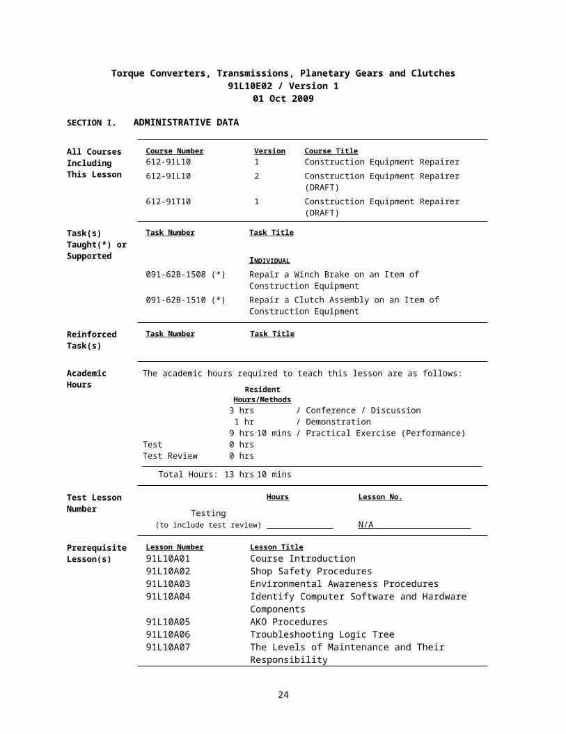
Torque Converters, Transmissions, Planetary Gears and Clutches91L10E02 / Version 1
01 Oct 2009
SECTION I. ADMINISTRATIVE DATA
All Courses Including This Lesson
Course Number Version Course Title612-91L10 1 Construction Equipment Repairer612-91L10 2 Construction Equipment Repairer (DRAFT)612-91T10 1 Construction Equipment Repairer (DRAFT)
Task(s)Taught(*) orSupported
Task Number Task Title
INDIVIDUAL 091-62B-1508 (*) Repair a Winch Brake on an Item of Construction Equipment091-62B-1510 (*) Repair a Clutch Assembly on an Item of Construction
Equipment
Reinforced Task(s)
Task Number Task Title
Academic Hours
The academic hours required to teach this lesson are as follows:
ResidentHours/Methods3 hrs / Conference / Discussion1 hr / Demonstration
9 hrs 10 mins / Practical Exercise (Performance)Test 0 hrsTest Review 0 hrs
Total Hours: 13 hrs 10 mins
Test Lesson Number
Hours Lesson No.
Testing(to include test review) N/A
Prerequisite Lesson(s)
Lesson Number Lesson Title91L10A01 Course Introduction91L10A02 Shop Safety Procedures91L10A03 Environmental Awareness Procedures91L10A04 Identify Computer Software and Hardware Components91L10A05 AKO Procedures91L10A06 Troubleshooting Logic Tree91L10A07 The Levels of Maintenance and Their Responsibility91L10A08 Utilize Maintenance and Repair Parts Technical
Manuals 91L10A09 Utilize Maintenance Forms and Records91L10A10 Battlefield Damage Assessment and Repair (BDAR)91L10A11 Identify Items of Construction Equipment91L10A12 Identify Test, Measurement and Diagnostic Equipment
(TMDE), general mechanics and special tools.91L10A13 Shop Operations Examination91L10B01 The Fundamentals of Electricity91L10B02 Wiring Diagrams, Schematics, and Automotive
Batteries.
20

91L10B03 Identify Test, Measurement and Diagnostic Equipment (TMDE)
91L10B04 Starting and Charging Systems91L10B05 Electrical Systems Examination91L10C01 Diesel Engine Principles91L10C02 Disassembly/Assembly of a Diesel Engine 91L10C03 Diesel Engine Component Replacement Performance
Evaluation91L10C04 Diesel Engine Systems Written Examination91L10C05 Diesel Engine Test and Adjustment Procedures91L10C06 Diesel Engine Systems Performance Evaluation91L10D01 Hydraulic System Fundamentals91L10D02 Hydraulic Cylinders and Lines91L10D03 Hydraulic Pumps and Control Valves91L10D04 Hydraulic Accumulators91L10D05 Hydraulic Schematics91L10D06 Hydraulic Systems Examination91L10E01 Power Train Gears, Bearings and Seals
Clearance Access
Security Level: UnclassifiedRequirements: There are no clearance or access requirements for the lesson.
Foreign Disclosure Restrictions
FD7. This product/publication has been reviewed by the product developers in coordination with the Fort Leonard Wood, MO / Maneuver Support Center foreign disclosure authority. This product is NOT releasable to students from foreign countries.
21

ReferencesNumber Title Date
Additional Information
29 CFR 1910.1200 Hazard Communication 01 Jul 200329 CFR 1910.132 Personnel Protective
Equipment - General Requirements
01 Jul 2003
29 CFR 1910.133 Eye and Face Protection 01 Jul 200329 CFR 1910.136 Foot Protection 01 Jul 200329 CFR 1910.138 Hand Protection 01 Jul 200329 CFR 1910.147 The Control of
Hazardous Energy (Lockout/Tagout).
01 Jul 2003
29 CFR 1910.95 Occupational Noise Exposure
01 Jul 2003
AR 385-10 The Army Safety Program
23 Aug 2007
EM 385-1-1 Safety and Health Requirements.
03 Nov 2003 Public Domain
FM 3-100.4 Environmental Considerations in Military Operations. MCRP 4-11B
15 Jun 2000 Public Domain
FM 5-19 (FM 100-14) Composite Risk Management.
21 Aug 2006 Public Domain
TM 5-2410-237-23 Unit and Direct Support Maintenance for Tracker, Full Tracked, Low Speed: Diesel Engine Driven, Medium Drawbar Pull Tractor with Ripper, Tractor With Winch, Tractor With Ripper and Winterized Cab, Tractor With Winch and Winterized Cab...
15 Jul 2005 EM 0119; Public Domain
TM 5-3805-248-23-1 Unit and Direct Support Maintenance for Scraper, Earth Moving, Motorized, Diesel Engine Driven Model 621B (NSN 3805-01-153-1854) (EIC: EH3).
15 Feb 2006 EM 0115; Public Domain
TM 5-3805-248-23-2 Unit and Direct Support Maintenance for Scraper, Earth Moving, Motorized Diesel Engine Driven Model 621B.
15 Feb 2006 EM 0115; Public Domain
TM 5-3805-290-23-1 Field Maintenance Manual for Loader, Light, Scoop; 2.5 Cubic Yard Multipurpose (MP) Clamshell Bucket, Diesel Engine Driven (DED), 4-Wheel Drive.
30 Nov 2007 Public Domain
22

TM 5-3805-290-23-2 Field Maintenance Manual for Loader, Light, Scoop: 2.5 Cubic Yard Clamshell Bucket, Diesel Engine Driven (DED), 4-Wheel Drive Caterpillar Model 924G.
30 Nov 2007 Public Domain
TM 9-4910-571-12&P Operator's and Organizational Maintenance Manual Including Repair Parts and Special Tools List for Simplified Test Equipment for Internal Combustion Engines (NSN 4910-01-124-2554).
25 Mar 1988 Distribution Restricted
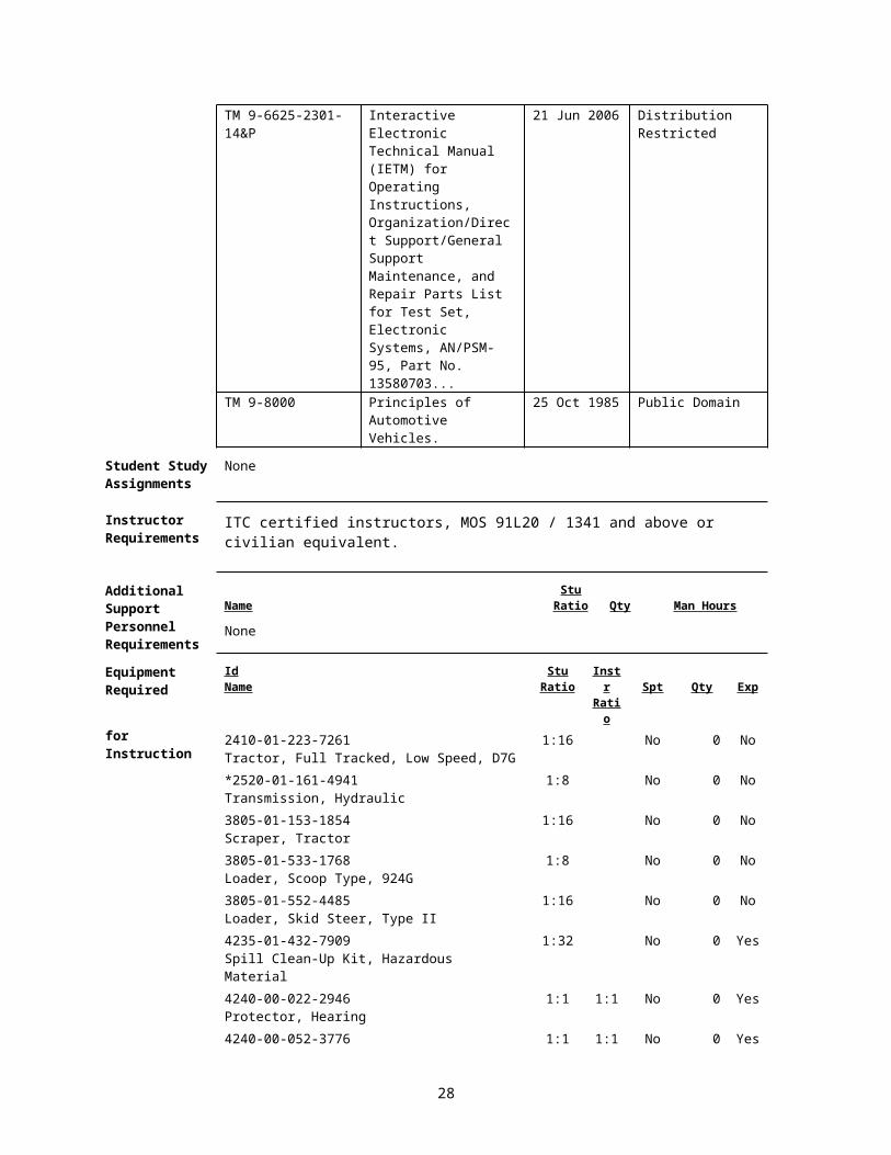
TM 9-6625-2301-14&P
Interactive Electronic Technical Manual (IETM) for Operating Instructions, Organization/Direct Support/General Support Maintenance, and Repair Parts List for Test Set, Electronic Systems, AN/PSM-95, Part No. 13580703...
21 Jun 2006 Distribution Restricted
TM 9-8000 Principles of Automotive Vehicles.
25 Oct 1985 Public Domain
Student Study Assignments
None
Instructor Requirements
ITC certified instructors, MOS 91L20 / 1341 and above or civilian equivalent.
Additional Support Name
Stu Ratio Qty Man Hours
Personnel Requirements
None
Equipment Required
IdName
Stu Ratio
Instr Ratio Spt Qty Exp
for Instruction 2410-01-223-7261Tractor, Full Tracked, Low Speed, D7G
1:16 No 0 No
*2520-01-161-4941Transmission, Hydraulic
1:8 No 0 No
3805-01-153-1854Scraper, Tractor
1:16 No 0 No
3805-01-533-1768Loader, Scoop Type, 924G
1:8 No 0 No
3805-01-552-4485Loader, Skid Steer, Type II
1:16 No 0 No
4235-01-432-7909Spill Clean-Up Kit, Hazardous Material
1:32 No 0 Yes
4240-00-022-2946Protector, Hearing
1:1 1:1 No 0 Yes
4240-00-052-3776Goggles, Industrial
1:1 1:1 No 0 Yes
23
4240-01-253-6042Fountain, Eye and Face Wash
1:32 No 0 No
4910-00-251-6981Creeper, Mechanic's
1:8 No 0 Yes
4910-00-357-5342Table, Work, Automotive Maintenance
1:4 No 0 No
*5180-01-502-9507BDAR Maintainer Kit
1:32 No 0 No
5180-01-548-7634Tool Kit, General Mechanic
1:4 No 0 No
7000-21-000-0354150" Video Screens
Yes 4 No
7000-21-000-0355Screen Controller
Yes 4 No
7000-21-000-0356Crestron Audio / Video Controller
Yes 1 No
7000-21-000-0357Power Supply
Yes 1 No
7000-21-000-0358Crestron Com Card
Yes 3 No
7000-21-000-0359LCD Projection System
Yes 4 No
7000-21-000-03608x8 RGB Routing Switcher
Yes 1 No
7000-21-000-0361Creston Ethernet Card
Yes 1 No
7000-21-000-0362Creston Input/Output Card
Yes 2 No
7000-21-000-0363Crestron Volume Control Card
Yes 2 No
7000-21-000-0364Crestron Relay Card
Yes 1 No
7000-21-000-0365Crestron RS-232/IR Control Card
Yes 1 No
7000-21-000-0366Crestron Infrared Transmitter
Yes 2 No
7000-21-000-0367Ceiling Speaker System
Yes 16 No
7000-21-000-0368Crestron Lighting Controller
Yes 2 No
7000-21-000-0369Crestron 12" Video Touch Panel
Yes 2 No
7000-21-000-0385Projector Mounting System
Yes 4 No
7000-21-000-0386Audio Power Amplifier
Yes 4 No
7000-21-000-0387Headset Microphone
Yes 2 No
7000-21-000-0388Condenser Microphone
Yes 2 No
7000-21-000-0389Microphone Base
Yes 2 No
7000-21-000-0390Power Conditioner
Yes 2 No
24

7000-21-000-03918x8 Audio Video Routing Switcher
Yes 1 No
7000-21-000-0392VCR / DVD Player
Yes 2 No
7000-21-000-0393VCR / DVD Control Module
Yes 2 No
7000-21-000-0394Wireless Microphone System
Yes 2 No
7000-21-000-0395Lavaliere Microphone
Yes 2 No
7000-21-000-0396Audio Dynamics Processor
Yes 1 No
7000-21-000-0397Microphone Mixer
Yes 2 No
7000-21-000-0398Audio Routing Mixer
Yes 1 No
7000-21-000-039920 Space Security Door
Yes 1 No
7000-21-000-04002-Space Vented Security Panel
Yes 2 No
7000-21-000-0401Document Camera
Yes 2 No
7000-21-000-0402Wireless Mouse
Yes 2 No
7000-21-000-04031x2 RGB Distribution Amplifier
Yes 2 No
7000-21-000-0404Audio/Video/Control Cable and Assemblies
Yes 2 No
7000-21-000-0405Control System Design
Yes 40 No
7000-21-000-0406Smart Board Display Monitor
Yes 2 No
7000-21-000-0407Documentation for Installation Schematics
Yes 10 No
7000-21-000-0408Rack
Yes 1 No
7000-21-000-0409Instructor PC
Yes 2 No
7110-01-202-3674Board, Marker, Dry, Erasable Type
1:1 No 0 No
7195-00-477-5699Stand, Lecture
1:1 No 0 No
8405-00-131-6508Coveralls, Men's OG 46M
1:1 Yes 0 No
8430-00-624-3135Boots, Safety, Men's, Size 10 Regular
1:1 Yes 0 No
8435-01-475-6874Boots, Safety, Women's, Size 8 Regular
1:1 Yes 0 No
* Before Id indicates a TADSS
Materials Required
Instructor Materials: TM 5-2410-237-23TM 5-3805-248-23-1TM 5-3805-248-23-2
25

TM 5-3805-262-20TM 5-3805-262-24PTM 5-3805-262-34TM 9-8000FOS 40FOS 54POLCaterpillar Dealer Training Course Guide 27Caterpillar Training Guide 33, Basic Power Shift - Planetary GearingCaterpillar Training Guide 44, Basic Power Shift - Torque Converters29 CFR 1910.1200 Hazard Communication 01 Jul 200329 CFR 1910.132 Personnel Protective Equipment 01 Jul 2003
General Requirements29 CFR 1910.133 Eye and Face Protection 01 Jul 200329 CFR 1910.136 Foot Protection 01 Jul 200329 CFR 1910.138 Hand Protection 01 Jul 200329 CFR 1910.95 Occupational Noise Exposure 01 Jul 2003Hearing ProtectionEye Protection
Student Materials: TM 5-2410-237-23TM 5-3805-248-23-1TM 5-3805-248-23-2TM 5-3805-262-20TM 5-3805-262-24PTM 5-3805-262-34Student GuidesPens and PencilsHearing ProtectionEye ProtectionSafety BootsCoverallsWork Gloves
Classroom, Training Area, and Range Requirements
AUTO-AID INST, 1400 SF (Classroom XXI)VEH MAINT INST
Ammunition Requirements Id Name Exp
Stu Ratio
Instr Ratio
Spt Qty
None
Instructional Guidance
NOTE: Before presenting this lesson, instructors must thoroughly prepare by studying this lesson and identified reference material.
Before presenting this lesson:
a. Ensure classroom is available and ready for training.
b. Ensure overhead projector and computer is on hand and ready for instruction.
c. Ensure all materials are on hand and in quantities needed.
d. Read and understand Lesson E02 prior to conducting training.
26

e. Conduct an Environmental Risk Assessment for this lesson IAW FM 3-100.4, Environmental Considerations in Military Operations.
1) The assessment is to be recorded on the Risk Management Worksheet found in appendix F of FM 3-100.4. FM 5-19, Composite Risk Management, has more information on this worksheet.
2) During the assessment instructors should look for environmental hazards including all activities that may pollute, generate hazardous or solid waste, create negative noise-related effect, degrade archaeological, cultural resources, or negatively affect threatened or endangered species’ habitats.
3) Ensure instructor check Contemporary Operational Environment web site for latest updates.
https://sp.wood.army.mil/sites/Manscen/ENG/1bde/169/ACO2/COA/Tab4.aspx
f. In accordance with AR 385-10, Army Safety Program, Chapter 16, Occupational Safety and Health Program (Workplace Safety):
1) OSHA programs and national consensus standards shall be applicable to and integrated into all Army equipment, systems, operations, and workplaces, CONUS and OCONUS.
2) Military design, specifications, and deployment requirements will comply with OSHA standards where feasible. When no standard exists for military application or the application is not feasible, the Army component will apply mishap risk management component of CRM.
3) Military and Army civilian officials at each management level shall promote strong safety programs, safe working conditions, and safe performance to prevent accidents, injuries, and occupational illnesses.
Proponent Lesson Plan Approvals
Name
Shankland, Steven
Rank
SSG
Position
Developer/Writer
Date
27 Dec 2007
King, Ronnie YC-02 Chief, Construction Engineer Branch
27 Dec 2007
Rutledge, Jesse YC-02 Chief, Individual Training Division
27 Dec 2007
SECTION II. INTRODUCTION
Method of Instruction: Conference / Discussion Instructor to Student Ratio is: 1:32 Time of Instruction: 5 mins Media: Large Group Instruction
Motivator NOTE: Show Slide #1, Introduction
27
a. Introduction of the instructor and topic of instruction.
b. Explain the importance of being able to troubleshoot, repair or replace faulty torque converters, transmissions and clutches.
NOTE: Show Slide #2, TLO
c. State complete action, condition, standards, safety, and environmental considerations.
Terminal Learning Objective
NOTE: Inform the students of the following Terminal Learning Objective requirements.
At the completion of this lesson, you [the student] will:
Action: Identify the components and operation of torque converters, transmissions, planetary gears and clutches.
Conditions: In a contemporary operational environment, given items of construction equipment, training aids, technical manuals (TMs) applicable to each item of equipment, Personal Protective Equipment (PPE), TM 9-214, TM 9-8000, a study guide, a general mechanic’s tool kit, special tools, Test Measurement and Diagnostic Equipment (TMDE), standard shop equipment, a shop set #1 common, petroleum, oils, and lubricants (POL), repair parts, necessary maintenance forms, a pen, and a pencil.
Standards: Identify the components and operation of torque converters, transmissions, planetary gears and clutches. Implement transmission troubleshooting, repair, and adjustments.
Safety Requirements
There is a possibility of injury while lifting heavy objects during this lesson. Use proper lifting techniques and use lifting devices. Remove all jewelry to include ID tags and wedding bands when working on equipment. Use caution around moving parts. You will wear eye and foot protection when required by the instructor, while working around equipment. You will be provided and required to wear aural protectors while equipment is in operation. Follow all safety procedures. The use of Personal Protective Equipment (PPE) by students and instructors is mandatory. Further guidance concerning PPE can be found in OSHA regulations 29 CFR 1910.132; 29 CFR 1910.133; 29 CFR 1910.136; 29 CFR 1910.138; and 29 CFR 1910.95.
Risk Assessment Level
Medium - The risk assessment for this module has been reviewed and signed by the responsible officer. Review the deliberate risk assessment, perform a daily risk assessment, and ensure it is recorded on appropriate forms, signed by authorized command authority, and posted at the training site.
Environmental Considerations
NOTE: It is the responsibility of all Soldiers and DA civilians to protect the environment from damage.There is a possibility of environmental contamination by Petroleum, Oil and Lubricants (POL), fuel, and cleaning solvents. You will be briefed on the proper disposal of POL products and how to properly clean up spills prior to each practical exercise. Ensure spill kits are available and there location identified. Instructors should complete a risk assessment before conducting training, operations, or logistical activities. Risk assessments assist instructors in identifying potential
28

environmental hazards, develop controls, make risk decisions, implement controls, and ensure proper supervision and evaluation.
Evaluation Practical Exercise
Instructional Lead-In
NOTE: Introduce the lessons contained in this TSP.
NOTE: Explain to students that they will learn about the components and functions of the torque converter, power shift transmission and planetary gear.
SECTION III. PRESENTATION
1. Learning Step / Activity 1. Identify the components and operation of the dry clutch and torque converter.
Method of Instruction: Conference / DiscussionInstructor to Student Ratio: 1:32
Time of Instruction: 1 hr 20 minsMedia: Large Group Instruction
NOTE: Contemporary Operational Environment
At various times during the class, the instructor will stress the importance of the topic by conveying personal experience related to the topic of discussion. The instructor will also answer any questions relating to the experience.
NOTE: Show Slide #3
a. A conventional clutch provides a means of connecting and disconnecting the engine from the power train system.
A torque converter is an automatic fluid drive. It transmits engine torque by means of hydraulic force, shifting smoothly through an infinite number of speeds.
b. Basic Power Shift/Torque Converters: Let's look at a typical power train with a power shift transmission.
Power Train Components:
1) Engine.
2) Dry Clutch/Torque Converter.
3) Range Transmission.
4) Transfer Gear Assembly.
5) Drive Shafts.
6) Differentials and Final Drives.
NOTE: Show Slide #4
29

c. Dry Clutch.
1) The dry clutch consists of these components:
a) Flywheel.
Supplies the first friction surface. The smooth face of the flywheel is half of the clamping surface for the clutch disk.
NOTE: Show Slide #5
b) Pressure Plate (Attached to the Engine) DRIVE.
The pressure plate is attached directly to the flywheel and is the second friction surface for the clutch disk. The clutch disk is pinched between the pressure plate and the flywheel with heavy springs, pushing the pressure plate firmly against the clutch disk and forcing the clutch disk to turn with the fly wheel. Only when the release bearing is forced into the fingers of the pressure plate does the clutch disk release from the flywheel by compressing the springs in the pressure plate.
NOTE: Show Slide #6
c) Clutch disk (Attached to the transmission) DRIVEN.
The clutch disk is directly connected to the transmission and has a flexible hub in the center to help absorb the shock of being pinched between the flywheel and pressure plate. The outside of the clutch disk has wear material riveted to it. This friction material is similar to what is found on disk brake pads and wears out over time. This is why clutches need to be adjusted periodically over the life of the clutch disk.
NOTE: Show Slide #7
d) Release Bearing.
The release bearing is forces the pressure plate to release the clutch disk. The release bearing is controlled by the operator through the clutch pedal, either by cable or thru use of a slave cylinder. When the operator pushes the clutch in, the release bearing which rides on the hub and is connected to the throw out fork, rides forward pushing on the clutch release levers, pulling the pressure plate away from the clutch disk, releasing the clutch disk, and removing all drive to the transmission. This allows the operator to shift and stop the vehicle.
NOTE: Show Slide #8
2) The conventional clutch drives the transmission by sandwiching the clutch disk between the flywheel and pressure plate. The dry clutch is used in one vehicle, the Small Emplacement Excavator, and is used extensively on rock crushing units. Dry clutches in construction equipment have been replaced in most applications by torque converters.
NOTE: Show Slide #9
d. The torque converter-torque multiplying transmission provides fluid drive and automatically increases the turning or twisting effort exerted by the engine. The planetary range transmission provides forward and reverse drives in a number of speed ranges.
NOTE: Show Slide #10
30
e. The torque converter is a form of hydraulic coupling used to transmit power from an engine to a drive unit. There is no direct connection between the engine and the driven unit... no flywheel clutch, just the fluid drive mechanism.
There are two types of hydraulic mechanisms used to transmit power: The fluid coupling and the torque converter. Both are fluid drive devices that use the energy of fluid in motion to transmit power.
NOTE: Show Slide #11
f. You are going to hear the work "torque" used often in this lesson. Let’s identify what it means.
1) These tools - the crank, wrench and pry-bar are levers. Levers generate torque. A lever has one or two arms, and in use, pivots around a point called a fulcrum.
2) If the lever is attached to its fulcrum - as is the case with the crank and wrench - a push on its lever arm will twist the fulcrum.
NOTE: Show Slides #12 & 13
3) A push or pull - the applied force - exerted on the end of a wrench will twist the bolt. The twisting effort is torque.
g. Before we find out how torque converters work, let's find out why we use them. What are the advantages of torque converter drives over direct gear drive transmissions? Let's look at some.
NOTE: Show Slide #14
1) First, torque converter drive absorbs shock loads such as those developed in a pusher tractor and a scraper during loading. Other power train shocks and vibrations are cushioned, too.
NOTE: Show Slide #15
2) Torque converter drive keeps the engine from lugging down and stalling when the machine is working. This allows the engine to run the hydraulic system.
NOTE: Show Slide #16
3) When a tractor is dozing, the torque converter automatically provides the high torque multiplications needed to meet the increasing load without shifting. As the dozer "digs in" and slows down, working torque - push power – becomes greater.
NOTE: The instructor may give other advantages of the torque converter such as the need for the flywheel clutch is eliminated, the workload is picked up gradually, and the operator doesn't become as tired because less shifting is required.
NOTE: Transition into the fluid coupling.
h. Fluid Coupling: To understand the torque converter, we must first look at the basic fluid coupling.
i. The main advantage of the fluid coupling is that it eliminates tensional vibration and provides a smooth; jerk less acceleration because of the cushioning of the fluid medium between the two members.
NOTE: Show Slide #17
31

j. How does a fluid coupling work? If we have two electric fans face to face and fairly close together, and one fan is plugged in and running, the other fan will turn. It will be turned by the energy of the moving air from the operating fan.
In this example, the air is the fluid. Because the two fans are not close together and not enclosed, this sort of fluid coupling is not very efficient.
NOTE: Show Slide #18
k. Of course, we know the energy of a liquid in motion is greater than air in motion. Since a liquid weighs more than air, it transmits more force when in motion. To make a more efficient fluid coupling, oil is used as the fluid and the blades are mounted very close together and enclosed in housing.
NOTE: Show Slide #19
l. Here is a type of fluid coupling. The shape is somewhat like a doughnut or an inner tube for a wheel tire.
NOTE: Show Slide #20
m. Disassemble: When we take the coupling apart and separate the two halves, we can see a number of straight, radial blades extending from the inside to the outside edge. The blades on the right are a part of the housing. This part is called the pump or impeller. The blades on the left are part of the turbine.
NOTE: Show Slide #21
n. Turbine: When we take the turbine from the housing, we can see that the back looks more nearly like half a doughnut or an inner tube.
NOTE: Show Slide #22
o. When the turbine on the left is cut along the axis, its cross section will look like the illustration on the right. You will recognize this shape in the following schematic cross section of the fluid coupling.
NOTE: Show Slide #23
p. This schematic represents the fluid coupling. The pump or impeller is shown in red. The pump shaft connects to the engine flywheel. The turbine is shown in blue. The turbine output shaft connects to the drive unit.
The impeller and the turbine both turn in the housing. They are not directly connected together in any way. The housing is filled with oil.
NOTE: Show Slide #24
q. The basic principle of all fluid couplings is fluid at high velocity strikes a turbine and forces it to turn, driving the wheel. Thus torque is transmitted by fluid.
Operation: The fluid coupling consists of an impeller (pump), driven by the engine and a turbine mounted on the transmission input shaft. There is no metallic connection between the two members. The assembly is kept filled with oil under control of a relief valve, by means of high capacity pumps. When the crankshaft and impeller rotate, the oil is thrown by centrifugal force from the center to the outside edge of the impeller between the vanes. This increases the velocity of the oil and increases
32

its energy. The oil then enters the turbine vanes at the outside and flows toward the center, giving a rotating motion to the turbine.
NOTE: Show Slide #25
r. When the oil from the impeller strikes the turbine blades. The energy of the moving oil is absorbed by the turbine and starts the turbine turning.
NOTE: Show Slide #26
s. When the oil starts the turbine turning, as the oil strikes the turbine, it slows down and flows inward toward the center to re-enter the impeller.
When the oil leaves the turbine, it is flowing in the direction opposite the oil flow in the impeller and tends to oppose the impeller. This fact, as you will learn later, is an important difference between the fluid coupling and the torque converter.
NOTE: The heavier yellow arrow represents oil increasing speed and energy as it moves through the impeller. The smaller arrows represent oil slowing down and losing energy to the turbine.
NOTE: Show Slide #27
t. Oil Flow: Now let us look at the flow of oil a little more closely. Basically there are two types of oil flow in a fluid coupling, rotary flow (red arrows) and vortex flow (yellow arrows).
NOTE: Show Slide #28
u. Rotary Flow: This occurs when the oil is traveling with the impeller and the turbine in the direction of rotation. The impeller and the turbine must be traveling at nearly the same speed...like when the machine is "coasting" or when it is being "road" with little or no load. The oil is thrown outward by centrifugal force in both the impeller and the turbine (yellow arrows). The oil simply follows the impeller and turbine around and around (red arrows).
When we have rotary flow, there is minimum "slip" or difference in rotational speed between the impeller and the turbine. The turbine output torque is zero.
NOTE: Show Slide #29
v. Vortex Flow: This occurs when the oil is traveling through the impeller, across the turbine and inward through the turbine back to the impeller. The impeller is turning with the engine; the turbine is stalled or held stationary by a load. The oil traveling across and striking the turbine blades limits oil movement in the direction of rotation with the impeller. The oil flow path would look like a spiral - an imaginary coil of wire.
When we have vortex flow, there is maximum "slip" between the impeller and the turbine. The output torque is greater when the turbine is stalled.
NOTE: Show Slide #30
w. Under normal operating condition, the oil flow in a fluid will combine both rotary and vortex flow. The imaginary oil flow path will be like a coil of wire that loosens or becomes tighter depending upon the amount or degree of "slip" between the impeller and the turbine.
NOTE: Show Slide #31
33

x. To summarize, a fluid coupling transmits torque from the source of power to the driven unit. It consists of an impeller and a turbine, each having straight, flat, radial blades. As the impeller turns, it throws oil outward and across into the turbine blades. The energy of the oil in motion turns the turbine. The oil returns to the center, re-enters the impeller and the cycle is repeated. The fluid coupling cannot multiply torque.
NOTE: Show Slide #32
y. In a fluid coupling the input torque equals the output torque. The ratio is one to one.
z. Now let’s look at the torque converter.
NOTE: Show Slide #33
aa. This is a dozer torque converter. Later you will learn that it includes a torque divider, but for now we will only discuss the torque converter section.
1) This particular torque converter is an "instructional cutaway". The housing is cut away so we can see the working parts inside.
2) The housing turns with the diesel engine. The gear teeth (on the left) mesh with the diesel engine flywheel. The output shaft is on the right.
NOTE: Show Slide #34
ab. The torque converter rotates counter clockwise. In the cutaway section, we see the impeller (red), turbine (blue) and stator (green).
NOTE: Show Slide #35
ac. Looking more closely, we see that the impeller, turbine and stator blades are curved. Remember, a fluid coupling has a straight, flat, radial blade.
NOTE: Show Slide #36
ad. This is a cross section view of the torque converter cutaway showing:
1) The rotating housing.
2) The impeller blades.
3) The turbine.
4) The stator.
NOTE: Show Slide #37
ae. The rotating housing and impeller (red) turn with the engine, the turbine (blue) turns the output shaft, and the stator (green) is fixed-held stationary by the transmission housing. The oil flows upward from the rotating impeller, around the inside of the housing and downward past the turbine. From the turbine, oil is re-directed by the stator back to the impeller.
NOTE: Show Slide #38
af. Now let's look at a schematic of the torque converter. In this schematic, like the torque converter cutaway, the impeller is red, the turbine is blue and the stator and housing is green. The torque
34

converter is a fluid coupling with a stator...stationary reactor...added for torque multiplication. The stator is fastened to the housing. The impeller and turbine both turn around it.
1) The fluid coupling, you remember, doesn't have a stator. And, as the oil strikes the turbine, it is deflected or "bounces" back in a direction opposite the impeller. This oil still in motion has energy, but this energy opposes or acts against the impeller.
2) By adding a stator to our basic fluid coupling, we put this "lost energy" to work. As the oil strikes the turbine and is deflected in a direction opposite the impeller, the stator re-directs the oil into the impeller so the remaining energy is added to the impeller output. This increases or multiplies input torque. Thus, we have a torque converter...torque changer.
NOTE: Show Slide #39
ag. Operation: Like the fluid coupling, the torque converter impeller rotates with the engine, pushes the oil outward and across in the direction of rotation, striking the turbine blades.
NOTE: Show Slide #40
ah. The energy of the oil from the impeller turns the turbine. After striking the turbine the oil flows inward. As the oil leaves the turbine, it is moving in a direction opposite impeller rotation. The stator causes the oil to change direction, adding its energy to the oil flow in the impeller. This multiplies torque.
NOTE: Show Slide #41
ai. Illustrated here (left) is the flow sequence through a section of the converter:
(1) Impeller, (2) Turbine, (3) Stator - oil leaving turbine, and (4) stator-oil re-directed to enter impeller. Also, illustrated is a cross section (right of the torque converter for reference. The numbers (both left and right) correspond to indicate flow sequence.
As the impeller turns, the oil is being pumped by the impeller (1) striking the turbine blades (2). The energy of the oil in motion is transmitted to the turbine in the form of torque, turning the turbine. The oil is deflected by the turbine (2) and leaves in the direction opposite to the flow of oil from the impeller. This would act against the impeller, but the stator (3) re-directs the oil from the turbine (2). The oil, re-directed by the stator (4) enters the impeller in the direction of rotation adding to the impeller oil output, increasing torque.
NOTE: Show Slide #42
aj. Let's return to the torque converter cutaway again. Following the yellow arrows, we see the oil flow pushed outward from the impeller and around the housing into the turbine. It flows through the turbine transmitting torque to the output shaft as it leaves the turbine blades.
NOTE: Show Slides #43 & 44
ak. The oil strikes the stator, which re-directs it toward the direction of impeller rotation. The flow is guided upward to re-enter the impeller. This cycle is repeated over and over.
NOTE: Show Slide #45
al. In a torque converter, the input torque plus the reaction from the stator equals output torque. The output torque is greater than the input torque. Again, torque multiplication is the result of the stator redirecting the oil from the turbine into the impeller. The energy of this oil is added to oil entering the impeller.
35

NOTE: Show Slide #46
am. Various torque-multiplying units, like the torque converter, are combined with planetary range transmissions to make Power Shift Transmissions suited to different kinds of work. Wheel loaders, for example, work on short, fast cycles. They crowd, dig, reverse and turn, dump, back away and crowd the pile again. They don't move far, but they move fast, cycling a couple of times a minute.
NOTE: Show Slide #47
an. Here is the Wheel Loader Power Train. All power shift transmissions in loaders consist of a torque converter (red) coupled to a planetary range transmission (yellow). With this arrangement the operator can crowd the pile hard without stalling or lugging down the engine. Because the engine does not lug down, power is maintained for the hydraulic system.
NOTE: Show Slide #48
ao. The transmission oil supplies oil for the loader torque converter operation pump. The oil inlet port is just above the output shaft. The oil outlet port is in the converter support below the output shaft. Arrows indicate the oil flow in the torque converter. Oil must be maintained under pressure in the torque converter to reduce or minimize cavitations. Cavitations reduce converter efficiency. Cavitations are the formation of oil vapor bubbles around the blades.
NOTE: Show Slide #49
ap. This is a schematic of a simplified torque converter oil system. Besides being the medium for transmitting power, oil is necessary to reduce cavitations, carry away heat, and to lubricate torque converter components.
1) The torque converter oil system is usually combined with the transmission oil system. The typical oil system will consist of:
a) A hydraulic control valve.
b) Pressure relief valve.
c) Torque converter-inlet and outlet.
d) Orifice.
e) Oil cooler.
f) Oil sump.
g) Magnetic screen.
h) Oil pump.
i) Oil filter.
2) This completes the basic construction and operation of the torque converter.
NOTE: Show Slide #50, The End
NOTE: Conduct a check on learning and summarize the learning activity.
36

Determine if students have learned the material presented by:
1. Soliciting student questions and explanations.
2. Asking questions and receiving answers from the students.
3. Correct student misunderstandings.
2. Learning Step / Activity 2. Observe torque converter operation.
Method of Instruction: DemonstrationInstructor to Student Ratio: 1:16
Time of Instruction: 25 minsMedia: Training Aid
Instructor will demonstrate the movement of the fluid thru each individual component of the torque converter showing the movement and fluid flow from the impeller thru the turbine and finally into the stator. The instructor will insure the students understand the fluid flow thru the torque converter and how the stator increases torque by redirecting the fluid back into the same direction of the impeller when the turbine is slowed or stalled.
NOTE: Conduct a check on learning and summarize the learning activity.
Determine if students have learned the material presented by:
1. Soliciting student questions and explanations.
2. Asking questions and receiving answers from the students.
3. Correct student misunderstandings.
3. Learning Step / Activity 3. Identify power shift transmission / planetary gear components and their functions.
Method of Instruction: Conference / DiscussionInstructor to Student Ratio: 1:32
Time of Instruction: 1 hr 20 minsMedia: Large Group Instruction
NOTE: Contemporary Operational Environment
At various times during the class, the instructor will stress the importance of the topic by conveying personal experience related to the topic of discussion. The instructor will also answer any questions relating to the experience.
NOTE: Show Slide #1 a. Introduction of the instructor and topic of instruction. b. During your previous instructions, you learned the purpose of the Torque Converter and how it
creates extreme amounts of torque. Now, with this powerful component attached to (or mounted in
37

front of) our next major component we are able to use its full hydraulic to mechanical torque to increase torque smoothly to our transmission. This transmission can be referred to as the “Range Transmission” but is best known as the “Power Shift Transmission”, because of the power it receives from the torque converter. Now you will learn the principal functions of each component of the power shift transmission, how to rebuild one, and how it operates.
NOTE: Show Slide #2
c. Basic Power Shift Transmission/Planetary Gearing.
1) The purpose of a power shift transmission:
a) It allows you to shift into a different gear without interrupting the flow of power.
b) It enables you to change the vehicle direction and speed.
c) It provides gear ratio selection.
NOTE: Show Slide #3
2) The shifting console and lever on the operator's right or left represents one of the most significant developments in the history of earthmoving equipment...the power shift transmission. Here you can see that we control it by use of a lever. Some equipment has more than one lever to control the power shift transmission. Here, just this one will control both direction and speed.
NOTE: Show Slide #4
3) Power shift application: Power shift is now available in almost every type of earthmoving vehicle, and its popularity is increasing rapidly. Here we show you four. Three of the four, the MW24C Bucket Loader, the D7G Dozer, and the 621B Scraper will be used in some type of practical exercise dealing with the power shift transmission. Just looking at the outer casing of the Power Shift Transmission, however doesn’t do a whole lot for a 62B mechanic. What do we, as 62B mechanics, need to do?
NOTE: Show Slide #5
4) Clutch assembly: Removed from its housing, a power shift range transmission consists of a stack of clutches and planetary gear set that are mounted together in this manner. There are four clutches in this transmission. Let's look at the components of one of these clutches.
NOTE: Show Slide #6
5) Bronze Clutch Discs that have teeth on the inner diameter.
NOTE: Show Slide #7
6) Steel Clutch Plates that have notches on the outer diameter. They engage with pins mounted to the clutch house to prevent the steel clutch plates from rotating.
NOTE: Show Slide #8
7) Shown separately, the heavy yellow piece on the right is the clutch housing and a seal that sits in a groove of the housing. The piece in front of the housing that is yellow is the piston, but the piece right in front of it is a seal that sit in a groove of the piston. In front, and to the left of the piston is a bronze-faced disc, followed by a steel plate. The number of discs and plates will vary between
38

different clutches and different transmissions, but the discs and plates are always arranged alternately within the clutch.
NOTE: Show Slide #9
8) Completed Clutch Pack: Shown together, the heavy piece on the bottom is the clutch housing. Notice that the bronze disc plates are engaged with the ring gear, and that the steel plate’s notches are engaged with the pins that are receded into the clutch housing to prevent them from rotating.
NOTE: Show Slide #10
9) Power Flow: Oil is forced between the housing and the piston and into the oil groove in the piston. Oil pressure moves the piston to the right against the red disc and blue steel plates. The piston continues to move to the right until all of the red discs and blue plates are completely engaged and the spring compressed. Notice that the red discs are splined to the outer diameter of the ring gear. When the red discs and the blue plates are engaged, the ring gear is stopped.
NOTE: Show Slide #11
10) The hand, here, is acting like a clutch. It is holding the ring gear. When the sun gear is driving, and the ring gear is held, the planet gears will walk around the inside of the ring gear producing power. Any time you see a hand, lock, and or a red circle, power is being achieved by way of what was discuss in slide #11.
NOTE: Show Slide #12
11) Planet Gear Component: #1. Planetary Gears, some system have three, some four. #2. Planetary Carrier holds planet gears in place and provides an axis of rotation. #3. Ring Gear rotates and provides and surface of contact for planetary gear. #4. Sun Gear splined to the input or output shaft. Take a moment and establish this set-up of gears firmly in your minds.
NOTE: Show Slide #13
12) Lets examine the rotational relationship of the planet gears and the sun gear. In this case, the planet gears rotate in the opposite direction of the rotation of the sun gear. Take a moment and establish this relationship firmly in your minds. If the white ring gear is held so it cannot move, and the sun gear is driving, the planet gears will walk around the sun gear and inside the ring gear. Remember, in a planetary set, one member must drive, one member must be held, and the third member will transmit power.
NOTE: Show Slide #14
13) Another planetary gear set configuration is the addition of outer planetary gears, shown here in yellow. The yellow planet gears rotate in the same direction as the sun gear and ring gear. The ring gear would be driven and would be the member that transmits power, but it will be in reverse. Let’s examine the rotational relationship of this set-up. Let's see how these planetary gear sets are utilized in a power shift range transmission.
NOTE: Show Slide #15
14) There is a clutch and a planetary set for each transmission speed and for both directions, forward and reverse. This view shows the general arrangement of the clutches and planetary gear sets. Let's look at a simplified range transmission to see how the planetary gear sets and clutches actually transmit power.
39
NOTE: Show Slide #16
15) Operation: Each direction has a clutch and a planetary gearing set - reverse and forward; and each speed has a clutch and planetary set. We are going to work with a two-speed range transmission - second and first speeds.
a) Engine power is transmitted to the red input shaft by way of the torque converter or torque divider. The sun gears for reverse and forward are mounted to the input shaft and rotate whenever the input shaft is being driven. The gray piece in the center is a center carrier and carries the planet gears for forward and second speed.
b) The blue shaft is the output shaft, and the sun gears for the speed planetary sets are mounted on the output shaft.
c) Remember the arrangement of the planetary sets from the engine. Reverse, forward, second speed, and first speed. Let's break this model transmission into two parts, direction gears and speed gears.
NOTE: Show Slide #17
16) The direction half of the transmission:
a) Reverse and forward: Power is transmitted from the engine to the red input shaft. Which of these yellow ring gears is the reverse ring? Which is the forward ring?
b) This part of the transmission is now engaged in forward gear. The red input shaft is being driven and since the red sun gears are mounted on the input shaft, they, the sun gears, are also being driven. The reverse sun gear, the one on the left, is forcing its planet gears to rotate; but they are not transmitting power.
(1) Remember: For a planetary set to transmit power, drive; one member must drive, one member must be held, and the third member will then be driven. Since nothing is being held in the first planetary, no power is being transmitted.
(2) However, the second clutch has been engaged and has stopped the ring gear. The second sun gear is driving its planet gears. Since the ring gear is being held, the planet gears are being forced to revolve around the inside of the ring gear. The planet gears, then, will drive the carrier on which they are mounted; and the carrier will rotate in the direction indicated by the arrow.
(3) Look at this power flow again to be sure that you understand it.
NOTE: Show Slide #18
17) Again, showing the directional half of the transmission, we can see that something has been changed. The carrier for the first (reverse) planetary has been stopped by a clutch and the red input shaft is driving the first sun gear. The first sun gear is driving the green planet gears. What is happening to the reverse ring gear? The planet gears are driving it because the planet gears are forced to rotate in place.
a) They cannot revolve around the sun gear, because the carrier that holds them is stopped. With the green planet gears driving the reverse ring gear, we can see that the middle carrier is also being driven because it is attached to the reverse right gear. All components shown in red are transmitting power.
40

b) Notice the direction in which the large red carrier is now rotating. It rotates in the opposite direction of the input shaft.
18) Power Flow: Trace the flow of power in this scene. Where is the power input? What is being held? Which member is transmitting power?
NOTE: Instructor will insure that students understand the power flow before continuing.
NOTE: Show Slide #19
19) Now, looking at the speed gear half of the range transmission, we can see that the ring gear for second speed is stopped. The connecting carrier is rotating and causing the second speed planet gear to revolve around the inside of the ring gear. Since the ring gear is being held, and the planet gears are driving, the sun gear for second speed is being driven.
The ring gear for first speed, on the right, is idling, and its planetary gear set is not transmitting power.
NOTE: Show Slide #20
20) In first gear, the center (connecting) carrier is being driven. In turn, the center carrier is driving the red second speed ring gear. Notice that the second ring gear serves as the carrier mount for the first speed planet gears. When the red second speed ring gear is turning, it forces the first speed planet gears to "walk" around the inside of the first speed ring gear. Since the first speed ring gear is stopped by its clutch, the planet gears will drive the first speed sun gear.
NOTE: The load on the output shaft is restraining the second and first speed sun gears. This restriction in power is why the second speed ring is driven.
21) Lets review the first speed action. The center carrier is being driven. It drives the second speed ring gear, which, in turn, drives the first speed planet gears. Since the first speed ring gear is held by its clutch, the planet gears will walk around the inside of the ring gear; and they will drive the first speed sun gear and the output shaft.
NOTE: Show Slide #21
22) Looking again at our basic range transmission, we should remember that it consists of two principal gearing groups, a direction group which determines whether the vehicle will move forward or in reverse, and a speed group, which determines how fast the vehicle will move in either direction. Take a good look at the arrangement of the individual planetary gear sets and remember their order.
NOTE: Be sure that every student knows the planetary arrangement at this time before beginning a discussion of gearing combinations.
NOTE: Show Slide #22
23) Which ring gear is being held in this scene? It is the forward ring gear, reverse ring gear, second speed ring gear, first speed ring gear?
NOTE: Show Slide #23
Follow the power flow in this scene.
a) The input shaft is being driven. Nothing is being held in the reverse planetary set, but we can see that the forward ring gear is being held. What does this signify?
41
b) With the forward ring gear clutch engaged, and the sun gear being driven, the forward planet gears are being driven. The forward planet gears cause the center, connecting carrier to rotate; and the center carrier will force the second speed planet gears to rotate. But, what happens in the speed gear group? Exactly nothing! Neither of the two speed ring gears is held, so there will not be any power delivered to the output shaft. The speed planetary gears are idling, because nothing is being held.
NOTE: Show Slide #24
24) Here we have a different situation. The first speed ring gear has been stopped.
Let's trace the power flow:
a) The input shaft is being driven, but nothing is being held in the direction gears group. Since nothing is being held, nothing is being driven. The center carrier is not going to deliver any power back to the speed gear group. Consequently, the engagement of the first speed ring gear clutch is not going to cause anything to happen. No power is being delivered to the output shaft. The transmission is in neutral.
b) These last two scenes have indicated a primary principle in caterpillar power shift. Both a direction ring gear clutch and a speed ring gear clutch must be engaged before the transmission will deliver any power through the output shaft.
NOTE: Show Slide #25
25) Which ring gears are being held in this scene?
a) Forward and First Speed. The input shaft is driven. Nothing happens in the reverse planetary, because nothing is being held. The forward ring gear is stopped, so the rotating sun gear forces the planet gears to walk around the inside of the forward ring gear. The forward planet gears are mounted on the center carrier, so the center carrier is forced to turn.
b) The rotating center carrier forces the second speed planet gears to drive the second speed ring gear. The second speed ring gear then turns the first speed planet gears. Since the first speed ring gear is being held, the planet gears drive the first speed sun gear and delivers power to the output shaft. The vehicle will now move forward in first speed.
NOTE: Show Slide #26
26) In this scene, we can see what the gearing selection is: forward, second speed.
Input power from the input shaft causes the forward sun gear to drive the forward planet gears. Since the forward ring gear clutch is holding the ring gear, the planet gears will walk around the inside of the forward ring gear and cause the center carrier to rotate. The center carrier forces the second speed planet gears to walk around the inside of the second speed ring gear. Since the second speed ring gear is held, the planet gears force the sun gear to rotate. Power is then transmitted to the output shaft.
NOTE: Show Slide #27
27) What gear combination is this? Reverse - Second Speed.
a) Notice that the reverse carrier is being held, not the ring gear. This means that the input shaft and reverse sun gear are forcing the reverse planet gears to rotate, but - the reverse planet gears cannot walk around the inside of the reverse ring gear for two reasons: The
42

carrier holding the planet gears is being held by a clutch, and the reverse ring gear is not being held. Consequently, it is the ring gear that is forced to rotate and transfer the power to the center carrier. Do you understand how the reverse ring gear transfers power to the center carrier?
b) The center carrier will rotate and cause the second speed planet gears to walk around inside of the ring gear. The second speed ring gear is being held, so the planet gears will drive the sun gear and the output shaft.
c) Notice that the output rotation is reversed from the input rotation.
NOTE: Show Slide #28
28) We can readily see that this transmission is in Reverse, but which speed clutch is engaged? First Speed.
Remember that in reverse the carrier is held, and the planet gears rotate in place and drive the reverse ring gear. The reverse ring gear in turn, causes the center carrier to rotate and drive the second speed ring gear. The second speed ring gear is connected to the carrier of the first speed planetary set, so the first speed planetary gears are driven. Since the first speed ring gear is held, the planet gears walk around the inside of the ring gear and drive the first speed sun gear and the output shaft.
29) Power Shift Transmission:
Description: So far we have been examining a highly simplified power shift transmission in order to obtain a basic understanding of the relationship of the planetary gear set. At this point, we will start construction of a more realistic transmission. Let's begin with the basic components of a typical transmission.
NOTE: Show Slide #29
30) Major Input Components:
The red half of this shaft is the Input Shaft. The input shaft also holds the reverse and forward sun gears. As you will recall, the simplified transmission that we just examined has its sun gears arranged on the shaft in similar fashion.
NOTE: Show slide #30
31) Major Output Components:
The blue shaft is the Output Shaft. It holds the sun gears for second and first speeds. The flared end of the shaft is mounted to the universal joint.
NOTE: Show Slide #31
Here we show both shafts. Let’s begin our process of building a simplified power shift transmission.
NOTE: Show Slide #32
32) What’s next??? Planetary Gears: Let's add some planetary gears to each sun gear and start building up a basic range transmission. Numbers are often given to these planetary gear sets. Starting from the left, the input side, they are numbered one, two, three, and four.
43

NOTE: Show Slide #33
33) Planetary carrier: We now start adding carriers for the planet gears. This is a typical carrier. Notice that the planet gears are supported by large round shafts mounted in the carrier housing. Carriers, as you will learn, appear in many shapes and sizes; but they all perform the same function - they are the supports for planetary gear shafts.
NOTE: Show Slide #34
Now we can add it to our system to make it look like this.
NOTE: Show Slide #35
34) What is the next carrier? The Center Carrier.
Center carrier operation: The center carrier is the component that connects the red input - direction shaft and the blue output- speed shaft, and it contains the planet gears for forward and second speed.
NOTE: Show Slide #36
Now we can add it to our system to make it look like this.
NOTE: Show Slide #37
35) What’s next? Front carrier: Here, we have added a front carrier for the first speed planetary gear set. Half of the carrier is cut away so that you can see how it is mounted and how it holds the planet gears.
NOTE: Show Slide #38
36) Starting from the left, the input side, they are numbered one, two, three, and four. Remember they are referred to as numbers rather than names such as: reverse, forward, first speed, and second speed. What else didn’t we name? Clutch Housing, Inner Seal, Outer Seal, Piston, Bronze Discs, Steel Plates, Ring Gear. Take a moment to familiarize yourself with the arrangement of the carriers, shafts, and planet gears.
NOTE: Show Slide #39
What do we need to complete this transmission? We need to put the entire assembly into a protective steel housing. Let's add these components now.
NOTE: Show Slide #40
37) Power shift range transmission: This is the range transmission cut in two. A service manual illustration will look essentially like this only there is less color. At first glance this scene looks complicated, but you should be able to identify several parts that you are familiar with.
a) The red shaft is the input shaft, and the reverse forward sun gears are mounted on it. The blue shaft is the output shaft, and the second speed and the first speed sun gears are mounted on it. The green parts are the planetary gears, and the gray pieces are the carriers. The front carrier on the left; the center carrier in the middle which carries the forward planet gears and the second speed planet gears; and on the right is the rear, or first speed carrier.
b) The small pink part in the center carrier is a lubrication tube that transfers oil through the center of the transmission. The tan areas represent the housing; and the clutches, shown in
44
light tan, are arranged around their respective planetary gear sets. The yellow parts are the ring gears. There is a connecting gear between the reverse planet gears and the forward carrier. This will be explained later.
NOTE: Show Slide #41
38) Forward and Second Speed Flow of Power: The red line in this scene represents the flow of power through the range transmission. The red circles in the area of the clutches designate the clutches that are engages. The second and third clutches, are engaged. However, the machine will be going in a Forward and Second speed.
a) Power enters through the red input shaft. The first, or reverse planetary gear set, is idling because nothing is being held. However, the second clutch, the forward clutch, is engaged and holding the ring gear. The red sun gear for forward is driving and the clutch is holding the ring gear, so the planet gears will force the gray center carrier to rotate.
b) The gray center carrier also holds the planet gears for the third planetary gear set, which is the second speed planetary, so the second speed planet gears are rotating. Notice that the second speed clutch is holding the ring gear. Consequently, the planet gears are forced to walk around the inside of the ring gear and they will force the sun gear to rotate and to transmit power to the blue output shaft.
NOTE: Show Slide #42
39) Forward - First Speed: Power enters through the red input shaft. The first, or reverse, planetary set is idling; but the clutch for forward is holding the forward ring gear. Since the forward sun gear is driving the forward planet gears, they will walk around the inside of the ring gear. Since the forward planet gears are mounted in the center carrier, they force the center carrier to rotate. Follow the red lines through the center carrier. Since the number three, or the second, planet gears are also mounted in the center carrier, they will rotate with the center carrier. The number three planet gears are now driving the number three-ring gear. Notice that the yellow, number three-ring gear extends to your right and splines to the left side of the rear carrier. Consequently, the rotation of the number three-ring gear will force the rear carrier to rotate. The green, number four, planet gears, since they are mounted in the rear carrier, will be forced to rotate. Number four, yellow, ring gear, on the far right, is being held by its clutch. This means that the number four planet gears will walk around inside of their ring gear, and they will drive the number four-sun gear and the shaft.
NOTE: Trace the power flow again for this scene.
NOTE: Show Slide #43
40) What gear combination do you see here? Reverse - Second Speed. Trace the power flow depicted in this scene.
41) There is no great mystery surrounding the power shift transmission. It is essentially a series of planetary gear sets surrounded by clutches. These clutches stop and hold ring gears or carriers, and thus allows power to be transmitted through the planetary sets. Power cannot be transmitted unless both a direction and a speed clutch have been engaged. Power shift range transmissions vary in size and configuration; but essentially, they all modify and transmit power in the same manner.
NOTE: Show Slide #44
42) What gear combination do you see here? Reverse-First Speed.
45

Notice how the first clutch (on the left) holds the ring gear that is splined to the reverse carrier. This ring gear, in turn, holds the reverse carrier in place so that it cannot rotate. The input shaft and the reverse sun gear will then drive the reverse planet gears. The planet gears will rotate in place and thus drive the yellow ring gear. This ring gear is splined to the left side of the center carrier so it forces the center carrier and the number two planet gears to rotate. There is no power being transmitted in the number two planetary set because nothing is being held. The center carrier rotates and causes the number three planet gear's to drive their ring gear. The number three ring gear is splined to the left end of the rear carrier, so the rear carrier and its planet gears also revolve. Since the number four clutch is engaged, holding the ring gear, the number four planet gear drives the number four sun gear and the output shaft. Result: reverse - first speed.
NOTE: Show Slide #45, The End
NOTE: Conduct a check on learning and summarize the learning activity.
Determine if students have learned the material presented by:
1. Soliciting student questions and explanations.
2. Asking questions and receiving answers from the students.
3. Correct student misunderstandings.
4. Learning Step / Activity 4. Observe power shift transmission operation.
Method of Instruction: DemonstrationInstructor to Student Ratio: 1:16
Time of Instruction: 25 minsMedia: Training Aid
This demonstration will be conducted as a round robin at two stations. 12 minutes are allotted for each station. After 12 minutes, the students will rotate.
a. Station #1: Transmission Component Identification and Inspection.
The instructor will:
1) Explain how to identify the forward and reverse planetaries.
2) Remove the piston, explain how it works and identify the inner and outer seals.
3) Explain how the clutch plates work together.
4) Show students how to inspect the clutch piston, inner and outer seals and inspect the clutch plates according to the technical manual.
b. Station #2: Transmission Operation.
The instructor will:
1) Turn on the operational transmission training aid and walk the students through the operation of the transmission.
46
2) Engage the gears one at a time and explain how the transmission engages different gears.
NOTE: Conduct a check on learning and summarize the learning activity.
Determine if students have learned the material presented by:
1. Soliciting student questions and explanations.
2. Asking questions and receiving answers from the students.
3. Correct student misunderstandings.
5. Learning Step / Activity 5. Implement transmission troubleshooting, repair, and adjustments.
Method of Instruction: Practical Exercise (Performance)Instructor to Student Ratio: 1:4
Time of Instruction: 9 hrs 10 minsMedia: Training Aid
Practical Exercise Instructions.
a. Give detailed instructions on what is expected during the practical exercise IAW Appendix B.
b. Ensure students have required materials and references IAW Appendix C.
c. Clarify students’ questions.
d. Conduct the practical exercise IAW Appendix C.
e. Check on students’ progress and provide assistance as necessary throughout the exercise.
f. Ensure students’ complete the practical exercise within the allotted time.
g. Provide solutions to the practical exercise.
NOTE: Conduct a check on learning and summarize the learning activity.
SECTION IV. SUMMARY
Method of Instruction: Conference / Discussion Instructor to Student Ratio is: 1:32 Time of Instruction: 5 mins Media: Large Group Instruction
Check on Learning
Determine if the students have learned the material presented by soliciting student questions and explanations. Ask the students questions and correct misunderstandings.
Review / NOTE: Show Slide #46
47

Summarize Lesson Restate the Terminal Learning Objective (TLO) (Identify the components and
operation of torque converters, transmissions, planetary gears and clutches). Summarize the Learning Steps/Activities.
1. Identify the components and operation of the dry clutch and torque converter.
2. Observe torque converter operation.
3. Identify power shift transmission / planetary gear components and their functions.
4. Observe power shift transmission operation.
5. Implement transmission troubleshooting, repair, and adjustments.
48
SECTION V. STUDENT EVALUATION
Testing Requirements
NOTE: Describe how the student must demonstrate accomplishment of the TLO. Refer student to the Student Evaluation Plan.
Feedback Requirements
NOTE: Feedback is essential to effective learning. Schedule and provide feedback on the evaluation and any information to help answer students' questions about the test. Provide remedial training as needed.
49
Differentials and Axles91L10E03 / Version 1
01 Oct 2009
SECTION I. ADMINISTRATIVE DATA
All Courses Including This Lesson
Course Number Version Course Title612-91L10 1 Construction Equipment Repairer612-91L10 2 Construction Equipment Repairer (DRAFT)612-91T10 1 Construction Equipment Repairer (DRAFT)
Task(s)Taught(*) orSupported
Task Number Task Title
INDIVIDUAL 091-62B-1502 (*) Replace a Driveshaft on an Item of Construction Equipment091-62B-1503 (*) Replace Universal Joints on an Item of Construction
Equipment091-62B-1506 (*) Replace a Differential on an Item of Construction Equipment
Reinforced Task(s)
Task Number Task Title
Academic Hours
The academic hours required to teach this lesson are as follows:
ResidentHours/Methods
1 hr 5 mins / Conference / Discussion30 mins / Demonstration
5 hrs 30 mins / Practical Exercise (Performance)Test 0 hrsTest Review 0 hrs
Total Hours: 7 hrs 15 mins
Test Lesson Number
Hours Lesson No.
Testing(to include test review) N/A
Prerequisite Lesson(s)
Lesson Number Lesson Title91L10A01 Course Introduction91L10A02 Shop Safety Procedures91L10A03 Environmental Awareness Procedures91L10A04 Identify Computer Software and Hardware Components91L10A05 AKO Procedures91L10A06 Troubleshooting Logic Tree91L10A07 The Levels of Maintenance and Their Responsibility91L10A08 Utilize Maintenance and Repair Parts Technical
Manuals 91L10A09 Utilize Maintenance Forms and Records91L10A10 Battlefield Damage Assessment and Repair (BDAR)91L10A11 Identify Items of Construction Equipment91L10A12 Identify Test, Measurement and Diagnostic Equipment
(TMDE), general mechanics and special tools.91L10A13 Shop Operations Examination91L10B01 The Fundamentals of Electricity91L10B02 Wiring Diagrams, Schematics, and Automotive
50

Batteries. 91L10B03 Identify Test, Measurement and Diagnostic Equipment
(TMDE)91L10B04 Starting and Charging Systems91L10B05 Electrical Systems Examination91L10C01 Diesel Engine Principles91L10C02 Disassembly/Assembly of a Diesel Engine 91L10C03 Diesel Engine Component Replacement Performance
Evaluation91L10C04 Diesel Engine Systems Written Examination91L10C05 Diesel Engine Test and Adjustment Procedures91L10C06 Diesel Engine Systems Performance Evaluation91L10D01 Hydraulic System Fundamentals91L10D02 Hydraulic Cylinders and Lines91L10D03 Hydraulic Pumps and Control Valves91L10D04 Hydraulic Accumulators91L10D05 Hydraulic Schematics91L10D06 Hydraulic Systems Examination91L10E01 Power Train Gears, Bearings and Seals91L10E02 Torque Converters, Transmissions, Planetary Gears and
Clutches
Clearance Access
Security Level: UnclassifiedRequirements: There are no clearance or access requirements for the lesson.
Foreign Disclosure Restrictions
FD5. This product/publication has been reviewed by the product developers in coordination with the Fort Leonard Wood, MO / Maneuver Support Center foreign disclosure authority. This product is releasable to students from all requesting foreign countries without restrictions.
51
ReferencesNumber Title Date
Additional Information
29 CFR 1910.1200 Hazard Communication 01 Jul 200329 CFR 1910.132 Personnel Protective
Equipment - General Requirements
01 Jul 2003
29 CFR 1910.133 Eye and Face Protection 01 Jul 200329 CFR 1910.136 Foot Protection 01 Jul 200329 CFR 1910.138 Hand Protection 01 Jul 200329 CFR 1910.147 The Control of
Hazardous Energy (Lockout/Tagout).
01 Jul 2003
29 CFR 1910.95 Occupational Noise Exposure
01 Jul 2003
AR 385-10 The Army Safety Program
23 Aug 2007
EM 385-1-1 Safety and Health Requirements.
03 Nov 2003 Public Domain
FM 3-100.4 Environmental Considerations in Military Operations. MCRP 4-11B
15 Jun 2000 Public Domain
FM 5-19 (FM 100-14) Composite Risk Management.
21 Aug 2006 Public Domain
TM 5-3805-290-23-1 Field Maintenance Manual for Loader, Light, Scoop; 2.5 Cubic Yard Multipurpose (MP) Clamshell Bucket, Diesel Engine Driven (DED), 4-Wheel Drive.
30 Nov 2007 Public Domain
TM 5-3805-290-23-2 Field Maintenance Manual for Loader, Light, Scoop: 2.5 Cubic Yard Clamshell Bucket, Diesel Engine Driven (DED), 4-Wheel Drive Caterpillar Model 924G.
30 Nov 2007 Public Domain
TM 5-3805-290-23P Field Maintenance Manual Repair Parts and Special Tools List (RPSTL) for Loader, Light, Scoop: 2.5 Cubic Yard Multipurpose (MP) Clamshell Bucket, Diesel Engine Driven (DED), 4-Wheel Drive.
30 Nov 2007 Public Domain
TM 9-8000 Principles of Automotive Vehicles.
25 Oct 1985 Public Domain
Student Study Assignments
None
Instructor Requirements
ITC certified instructors, MOS 91L20 / 1341 and above or civilian equivalent.
52

Additional Support Name
Stu Ratio Qty Man Hours
Personnel Requirements
None
Equipment Required
IdName
Stu Ratio
Instr Ratio Spt Qty Exp
for Instruction 2410-01-565-2605Tractor, Full Tracked, Low Speed, D7RII
1:16 No 0 No
*2520-01-093-5841Axle Assembly, Automotive, Driving
1:8 No 0 No
*2520-01-149-1051Spider, U-Joint, Vehicular
1:8 No 0 No
*2520-01-181-6423Transmission, Hydraulic
1:16 No 0 No
*2520-01-191-6515Center Prop Shaft Assembly
1:16 No 0 No
*2520-01-440-4495Propeller Shaft
1:16 No 0 No
*2520-01-455-4722Final Drive, Vehicular
1:16 No 0 No
*2530-01-167-8052Steering Unit Assembly
1:16 No 0 No
2590-01-228-5802Stand, Vehicle Support
1:8 No 0 Yes
*3010-01-060-7087Prop Shaft with U-Joint
1:16 No 0 No
3805-01-533-1768Loader, Scoop Type, 924G
1:16 No 0 No
3805-01-560-2384Grader, Road, Motorized, 120M
1:16 No 0 No
3950-00-449-7005Trestle, Hoist, Portable
1:16 No 0 No
4235-01-432-7909Spill Clean-Up Kit, Hazardous Material
1:32 No 0 Yes
4240-00-052-3776Goggles, Industrial
1:1 1:1 No 0 Yes
4240-01-253-6042Fountain, Eye and Face Wash
1:32 No 0 No
4910-00-251-6981Creeper, Mechanic's
1:8 No 0 Yes
4910-01-265-0401Stand, Vehicle Support, 10 ton
1:2 No 0 No
5120-01-396-6072Wrench, Torque, 3/4"
1:16 No 0 No
*5180-01-502-9507BDAR Maintainer Kit
1:32 No 0 No
5180-01-548-7634Tool Kit, General Mechanic
1:4 No 0 No
7000-21-000-0354150" Video Screens
Yes 4 No
7000-21-000-0355Screen Controller
Yes 4 No
7000-21-000-0356Crestron Audio / Video Controller
Yes 1 No
53

7000-21-000-0357Power Supply
Yes 1 No
7000-21-000-0358Crestron Com Card
Yes 3 No
7000-21-000-0359LCD Projection System
Yes 4 No
7000-21-000-03608x8 RGB Routing Switcher
Yes 1 No
7000-21-000-0361Creston Ethernet Card
Yes 1 No
7000-21-000-0362Creston Input/Output Card
Yes 2 No
7000-21-000-0363Crestron Volume Control Card
Yes 2 No
7000-21-000-0364Crestron Relay Card
Yes 1 No
7000-21-000-0365Crestron RS-232/IR Control Card
Yes 1 No
7000-21-000-0366Crestron Infrared Transmitter
Yes 2 No
7000-21-000-0367Ceiling Speaker System
Yes 16 No
7000-21-000-0368Crestron Lighting Controller
Yes 2 No
7000-21-000-0369Crestron 12" Video Touch Panel
Yes 2 No
7000-21-000-0386Audio Power Amplifier
Yes 4 No
7000-21-000-0387Headset Microphone
Yes 4 No
7000-21-000-0388Condenser Microphone
Yes 2 No
7000-21-000-0389Microphone Base
Yes 2 No
7000-21-000-0390Power Conditioner
Yes 2 No
7000-21-000-03918x8 Audio Video Routing Switcher
Yes 2 No
7000-21-000-0392VCR / DVD Player
Yes 1 No
7000-21-000-0393VCR / DVD Control Module
Yes 2 No
7000-21-000-0394Wireless Microphone System
Yes 2 No
7000-21-000-0395Lavaliere Microphone
Yes 2 No
7000-21-000-0396Audio Dynamics Processor
Yes 2 No
7000-21-000-0397Microphone Mixer
Yes 1 No
7000-21-000-0398Audio Routing Mixer
Yes 2 No
7000-21-000-039920 Space Security Door
Yes 1 No
54
7000-21-000-04002-Space Vented Security Panel
Yes 1 No
7000-21-000-0401Document Camera
Yes 2 No
7000-21-000-0402Wireless Mouse
Yes 2 No
7000-21-000-04031x2 RGB Distribution Amplifier
Yes 2 No
7000-21-000-0404Audio/Video/Control Cable and Assemblies
Yes 2 No
7000-21-000-0405Control System Design
Yes 2 No
7000-21-000-0406Smart Board Display Monitor
Yes 40 No
7000-21-000-0407Documentation for Installation Schematics
Yes 2 No
7000-21-000-0408Rack
Yes 10 No
7000-21-000-0409Instructor PC
Yes 2 No
7110-01-202-3674Board, Marker, Dry, Erasable Type
1:1 No 0 No
7195-00-477-5699Stand, Lecture
1:1 No 0 No
8405-00-131-6508Coveralls, Men's OG 46M
1:1 Yes 0 No
8415-00-268-7868Gloves, Work, Men's and Women's
1:1 Yes 0 No
8430-00-624-3135Boots, Safety, Men's, Size 10 Regular
1:1 Yes 0 No
8435-01-475-6874Boots, Safety, Women's, Size 8 Regular
1:1 Yes 0 No
* Before Id indicates a TADSS
Materials Required
Instructor Materials: TM 5-2350-262-20-1TM 5-2350-262-20-2TM 5-3805-262-20TM 5-3805-262-24PTM 5-3805-262-34TM 9-214TM 9-8000FOS 40FOS 5429 CFR 1910.1200 Hazard Communication 01 Jul 200329 CFR 1910.132 Personnel Protective 01 Jul 2003
Equipment –General Requirements
29 CFR 1910.133 Eye and Face Protection 01 Jul 200329 CFR 1910.136 Foot Protection 01 Jul 200329 CFR 1910.138 Hand Protection 01 Jul 200329 CFR 1910.95 Occupational Noise 01 Jul 2003
ExposureEye Protection
55

Hearing Protection
Student Materials: TM 5-2350-262-20-1TM 5-2350-262-20-2TM 5-3805-262-20TM 5-3805-262-24PTM 5-3805-262-34TM 9-214TM 9-8000LO 5-3805-262-12Student GuidesPens and PencilsHearing ProtectionEye ProtectionSafety BootsCoverallsWork Gloves
Classroom, Training Area, and Range Requirements
AUTO-AID INST, 1400 SF (Classroom XXI)VEH MAINT INST
Ammunition Requirements Id Name Exp
Stu Ratio
Instr Ratio
Spt Qty
None
Instructional Guidance
NOTE: Before presenting this lesson, instructors must thoroughly prepare by studying this lesson and identified reference material.
Before presenting this lesson:
a. Ensure classroom is available and ready for training.
b. Ensure overhead projector, screen, and computers are ready for instruction.
c. Ensure all materials are on hand and in quantities needed.
d. Read and understand Lesson E03 prior to conducting training.
e. Conduct an Environmental Risk Assessment for this lesson IAW FM 3-100.4, Environmental Considerations in Military Operations.
1) The assessment is to be recorded on the Risk Management Worksheet found in appendix F of FM 3-100.4. FM 5-19, Composite Risk Management, has more information on this worksheet.
2) During the assessment instructors should look for environmental hazards including all activities that may pollute, generate hazardous or solid waste, create negative noise-related effect, degrade archaeological, cultural resources, or negatively affect threatened or endangered species’ habitats.
3) Ensure instructor check Contemporary Operational Environment web site for latest updates.
https://sp.wood.army.mil/sites/Manscen/ENG/1bde/169/ACO2/COA/
56

Tab4.aspx
f. In accordance with AR 385-10, Army Safety Program, Chapter 16, Occupational Safety and Health Program (Workplace Safety):
1) OSHA programs and national consensus standards shall be applicable to and integrated into all Army equipment, systems, operations, and workplaces, CONUS and OCONUS.
2) Military design, specifications, and deployment requirements will comply with OSHA standards where feasible. When no standard exists for military application or the application is not feasible, the Army component will apply mishap risk management component of CRM.
3) Military and Army civilian officials at each management level shall promote strong safety programs, safe working conditions, and safe performance to prevent accidents, injuries, and occupational illnesses.
Proponent Lesson Plan Approvals
Name
Shankland, Steven
Rank
SSG
Position
Developer/Writer
Date
27 Dec 2007
King, Ronnie YC-02 Chief, Construction Engineer Branch
27 Dec 2007
Rutledge, Jesse YC-02 Chief, Individual Training Division
27 Dec 2007
SECTION II. INTRODUCTION
Method of Instruction: Conference / Discussion Instructor to Student Ratio is: 1:32 Time of Instruction: 5 mins Media: Large Group Instruction
Motivator NOTE: Show Slide #1, Introduction
a. Introduction of the instructor and topic of instruction
b. State complete action, condition, standards, safety, and environmental considerations.
NOTE: Show Slide #2, TLO
c. Explain the importance of being able to identify differential and axle components and their functions.
Terminal Learning Objective
NOTE: Inform the students of the following Terminal Learning Objective requirements.
At the completion of this lesson, you [the student] will:
Action: Identify differential and axle components and their functions.
57
Conditions: In a contemporary operational environment, given TM 5-3805-262-20, TM 5-3805-262-34, TM 9-8000, a student guide, instruction on identifying differential and axle components and their functions, items of construction equipment, training aids, a general mechanics tool kit, special tools, TMDE, PPE, and a pen and pencil.
Standards: Identify differential and axle components and their functions. Replace a drive shaft, universal joints and a differential on an item of construction equipment or training aid. Perform all operations without damage to the equipment or environment and without injury to personnel.
Safety Requirements
There is a possibility of injury while lifting heavy objects during this lesson. Use proper lifting techniques and use lifting devices. Remove all jewelry to include ID tags and wedding bands when working on equipment. Use caution around moving parts. You will wear eye and foot protection when required by the instructor, while working around equipment. You will be provided and required to wear aural protectors while equipment is in operation. Follow all safety procedures. The use of Personal protective Equipment (PPE) by students and instructors is mandatory. Further guidance concerning PPE can be found in OSHA regulations 29 CFR 1910.132; 29 CFR 1910.133; 29 CFR 1910.136; 29 CFR 1910.138; and 29 CFR 1910.95.
Risk Assessment Level
Medium - The risk assessment for this module has been reviewed and signed by the responsible officer. Review the deliberate risk assessment, perform a daily risk assessment, and ensure it is recorded on appropriate forms, signed by authorized command authority, and posted at the training site.
Environmental Considerations
NOTE: It is the responsibility of all Soldiers and DA civilians to protect the environment from damage.There is a possibility of environmental contamination by Petroleum, Oil and Lubricants (POL), fuel, and cleaning solvents. You will be briefed on the proper disposal of POL products and how to properly clean up spills prior to each practical exercise. Ensure spill kits are available and there location identified. Instructors should complete a risk assessment before conducting training, operations, or logistical activities. Risk assessments assist instructors in identifying potential environmental hazards, develop controls, make risk decisions, implement controls, and ensure proper supervision and evaluation.
Evaluation Practical Exercise
Instructional Lead-In
NOTE: Introduce the lessons contained in this TSP.
SECTION III. PRESENTATION
1. Learning Step / Activity 1. Identify differential and axle components and their functions.
Method of Instruction: Conference / DiscussionInstructor to Student Ratio: 1:32
Time of Instruction: 45 minsMedia: Large Group Instruction
58
NOTE: Contemporary Operational Environment
At various times during the class, the instructor will stress the importance of the topic by conveying personal experience related to the topic of discussion. The instructor will also answer any questions relating to the experience.
a. The engine provides the torque to move the vehicle; let’s see how the engine torque is transferred to the drive wheels. We will do this by examining the propeller shaft.
NOTE: Show Slide #3
b. Propeller Shaft:
1) Purpose: The power, having been transmitted through an angle by means of a universal joint, is next carried along the power train by a device known as a propeller shaft, or drive shaft. Propeller shaft is the most commonly used term, however either may be used.
2) Propeller shafts may be solid or tubular. A solid shaft is somewhat stronger than a hollow shaft of the same diameter, but a hollow shaft is much stronger than a solid shaft of the same weight.
NOTE: Show Slide #4
c. Slip Joints:
1) Purpose: Because flexing of the suspension causes the axle housing to move forward and backward, and up and down, some provisions must be made to allow the propeller shaft to contract and expand. A device known as a slip joint provides the necessary telescopic action for the propeller shaft.
2) Construction: A slip joint consists of a male and female spline, a grease seal, and a lubrication fitting. The male spline is an integral part of the propeller shaft and the female portion is fixed to a universal joint directly behind the transmission or transfer case. As the axle housing moves backwards and forward, the slip joint gives freedom of movement in a horizontal direction and yet is capable of transmitting rotary motion.
NOTE: Show Slide #5
d. Location: The propeller shaft connects the power flow from the transmission to the differentials with universal joints that permit the shaft to be installed at varying angles.
NOTE: Show Slides #6 and 7
e. Purpose:
1) Transmit torque to the Axles: One function of the differential is to transmit engine torque to the drive axles.
2) Provide a gear reduction: Gear reduction is gained by the different sizes of gears used in the differential assembly, a smaller gear driving a larger gear.
3) Provide independent wheel speed: Independent wheel speed is probably the most important use of the differential. This way the drive axles may rotate freely and simultaneously at varying speeds at the same time. This is important particularly if the vehicle is not moving in a straight line. As a result, there is less wear and tear on the vehicle’s tires.
NOTE: Show Slide #8
59

f. Location: The differential can also be located in the front of a vehicle. This slide illustrates where they are located, one is in the rear of the truck and one is in the front and rear of the loader.
NOTE: Show Slide #9
g. Pinion drive gear: The first component we will look at in the differential is the pinion drive gear, which is meshed with the differential drive ring gear inside the differential and is driven by the vehicle drive shaft.
NOTE: Show Slide #10
h. Ring Gear: With the ring gear and the pinion gear, a 90-degree change of power flow is achieved.
NOTE: Show Slide #11
i. Gears working together: Here the pinion is working in conjunction with the ring gear. A differential is not simply used to change the direction of the power flow. That could be accomplished with the pinion and ring gears as shown here with the pinion being connected to the propeller shaft and the ring gear splined to the axle.
NOTE: Show Slides #12 & 13
j. Let’s take a look at an imaginary vehicle traveling down the highway and making 180-degree turn.
1) With a solid axle it is not possible for one wheel to travel a greater distance than the other without some tire slippage.
2) Also, the vehicle with the solid axle would continue in a straight line. Both rear wheels would be traveling at the same speed at the same time and front wheels would be forcing the vehicle around the turn. This would cause both the front and rear wheels to wear excessively. Many of the other stresses and strains would not be evident until a component such as the axle failed.
NOTE: Show Slide #14
k. To improve operation in turns, the inner drive wheel must slow down; the outer wheel thus turns at a higher speed. Power is basically transmitted to one wheel only. To do this we must divide power to both sides so that independent wheel speed may be achieved.
NOTE: Show Slide #15
l. Here we see that the differential housing is being bolted directly to the ring gear. This is the first step in achieving a differential assembly.
NOTE: Show Slide #16
m. Now that we have our differential housing bolted to our bevel ring gear we have to add the remaining components to it.
NOTE: Show Slide #17
n. Each axle fits through the side of the housing and into the side gear on each side of the differential. These two gears are known as side gears. In a differential these gears are splined to the axles and held in place by snap rings in some cases.
NOTE: Show Slide #18
60
o. To develop the differential one step further, a hole is drilled through both sides of the housing. Then a pin is inserted. This can serve as an axle for four more gears in the housing.
NOTE: Show Slide #19
p. The last gears to be covered are the differential spider gears. There can be up to four spider gears in the differential. In this slide we have cut the housing so you can see how the spider gears are mounted on the pin. This completes the components within the conventional differential.
NOTE: Show Slide #20
q. The components that make up the conventional differential are the pinion drive gear, ring gear, housing, spider pin, spider gear, side gear and the axles.
NOTE: Show Slide #21
r. When we drive the vehicle down the highway the power is divided equally to both drive wheels. Remember that the spider gears and the side gears are the components that allow independents wheel speeds in a conventional differential.
NOTE: Show Slide #22
s. Here is an illustration of a pinion and ring gear showing how the gears sets are matched. Note that the number of teeth stamped on each gear must be the same.
NOTE: Show Slide #23
t. With the conventional differential, a splash type lubrication system is utilized. Oil is picked up and splashed up around the gears. 80-90 wt oil is used for the lubrication.
NOTE: Show Slide #24, Components of No-Spin Differential
u. No-spin Differential. Purpose: To provide a means of improving traction effort at the driving wheels. When one wheel tends to slip from loss of traction, it is necessary that the differential prevents actual slippage and supply torque to the driving wheels only to extent that the wheels can utilize the torque without slipping. The components used are much the same as the components used in the conventional differential.
NOTE: Show Slide #25
v. Construction: First look at the spider and center cam assembly. Notice the square teeth for clutch engagement around the outside and the tapered teeth for disengagement on the inner cam.
NOTE: Show Slide #26
w. The cam is held in place by a snap ring, which allows movement. The cam key restricts this movement. You can see how a slight movement is enough to cause the teeth to rise out of their grooves due to misalignment allowing independent wheel speed.
As you can see, the driven clutch member has the same square teeth around the outside to mesh with the spider cam assembly. There are two of these assemblies, one on each side. On the inside, there are holdout rings which do just that. As the twisting motion moves the two pieces, the driven clutch member rides up on the hold out rings and slides smoothly around.
61

The driven clutch member is disengaged by a slight twist causing the driven clutch member to move outward.
NOTE: Show Slide #27
x. Next are the spring retainers, springs, and side members, two of each. The spring retainer's ride on the inside lip of the driven clutch member applying spring pressure from the spring to keep tension on the driven clutch remember. This is done in order to force it back into its normal position during non-turning situations. The spring retainer is splined externally into the driven clutch member. The springs maintain pressure on both sides of the spring retainer and the side gear. The side gears are splined internally to the axles and are powered by the axles. They are also externally splined to the driven clutch members during turns. These are the components of the no-spin differential; now take a close up look at the right turn, left turn, and straight-line operation.
NOTE: Show Slide #28
y. Here is a closer look of how the teeth are separated by the cam and holdout ring. The three different positions of the no-spin are shown. In the center, the vehicle would be going straight down the highway. Notice the position of the driven clutch members. The position to the left is while making a left turn. Notice the right driven clutch member has ridden up on the cam assembly, disengaging or freewheeling, the right differential. The driven clutch members allow independent wheel speed.
NOTE: Show Slide #29, Engaged and Disengaged
NOTE: Show Slide #30, Picture of a Scraper
z. Conventional Differential with Differential Lock.
NOTE: Use COE situations here.
Purpose: A differential lock directs power equally to both wheels by locking out the differential. This prevents the usual loss of traction when one wheel is slipping. The conventional with the differential lock is used in two different types of equipment in our inventory. They are the 621B Scraper/Earthmover and the 130G Grader.
NOTE: Show Slide #31
aa. This is another example from a 621B; the lock or clutch mechanism can be engaged by the use of a foot pedal.
NOTE: Show Slide #32
ab. This locks one axle to the housing by engaging the "dog tooth" gears. While engaged there is no differential action because the side gear is locked into the spider gear and housing.
NOTE: Show Slide #33
ac. Operation: The operator of the equipment controls the operation of the differential lock. It is activated by electric over hydraulics. There is a toggle switch located in the grader operator compartment. When activated it pushes on a clutch piston, forcing the clutch plates and disks together. When locked together it locks the right side gear to the housing, so as it rotates it also rotates all the gears within the differential. The only time the differential lock is used is in straight operation.
NOTE: Show Slide #34
62
ad. Axles. Purpose: Supports the weight of the vehicle and also drives the wheels connected to it. Construction equipment utilizes both front and rear wheel drive vehicles. We will cover three types of rear drive axles, one at a time.
NOTE: Show Slide #35
1) Semi-floating: The first axle we will cover is the semi-floating axle. This axle supports 50% of the vehicles weight. This means that 50% of the weight of the vehicle is on the axle itself. When looking at this axle, the bearings ride on the axle. Also, the hub is directly mounted to the axle. If the axle should break, the vehicle would lose a wheel.
2) Three Quarter Floating: The next axle we will discuss only supports 25% of the vehicles weight. This is the three quarter floating axle. The bearings now ride on the outside of the axle housing and the hub is still directly mounted to the axle. If the axle should break, the vehicle would lose a wheel.
3) The Full Floating: This axle does not support any vehicle weight. Full floating means that all bearings are mounted to the axle housing. At the end of the axle, there is a gear called the sun gear. This gear works in conjunction with a planetary carrier gear and ring gear. This is the same type of planetary gear set that was covered in the powershift transmission class.
NOTE: Show Slide #36
a) Constant Velocity Joint: Now let's look at the different types of front axles in use today. Here we have the constant velocity universal joint. This axle is used as a steering axle. It is a full floating axle.
b) Cardan Axle: The last of the steering axles we will cover is the Cardan Axle. It is used as a steering axle and a full floating axle. It is nothing more than a splined solid steel shaft with universal joints.
NOTE: Conduct a check on learning and summarize the learning activity.
Determine if students have learned the material presented by:
1. Soliciting student questions and explanations.
2. Asking questions and receiving answers from the students.
3. Correct student misunderstandings.
2. Learning Step / Activity 2. Observe conventional and no-spin differential operation.
Method of Instruction: DemonstrationInstructor to Student Ratio: 1:16
Time of Instruction: 30 minsMedia: Training Aid
a. Instructors will divide the class into two groups.
b. One group will be taken to the conventional differential cutaway and one group to the no-spin differential cutaway.
63

c. Instructors will point out the construction of the differentials and demonstrate their operation to the class. Ask questions of the class and answer any questions they may have.
d. Groups will rotate after 15 minutes.
e. After the demonstration, transition to practical exercise.
NOTE: Conduct a check on learning and summarize the learning activity.
Determine if students have learned the material presented by:
1. Soliciting student questions and explanations.
2. Asking questions and receiving answers from the students.
3. Correct student misunderstandings.
3. Learning Step / Activity 3. Implement differential and axle troubleshooting, repair, replacement, and adjustment.
Method of Instruction: Practical Exercise (Performance)Instructor to Student Ratio: 1:4
Time of Instruction: 5 hrs 30 minsMedia: Training Aid
Practical Exercise Instructions.
a. Give detailed instructions on what is expected during the practical exercise IAW Appendix C.
b. Ensure students have required materials and references IAW Appendix C.
c. Clarify students’ questions.
d. Conduct the practical exercise IAW Appendix C.
e. Check on students’ progress and provide assistance as necessary throughout the exercise.
f. Ensure students’ complete the practical exercise within the allotted time.
g. Provide solutions to the practical exercise.
NOTE: Conduct a check on learning and summarize the learning activity.
Determine if students have learned the material presented by:
1. Soliciting student questions and explanations.
2. Asking questions and receiving answers from the students.
3. Correct student misunderstandings.
64

SECTION IV. SUMMARY
Method of Instruction: Conference / Discussion Instructor to Student Ratio is: 1:32 Time of Instruction: 5 mins Media: Large Group Instruction
Check on Learning
Determine if the students have learned the material presented by soliciting student questions and explanations. Ask the students questions and correct misunderstandings.
Review / Summarize Lesson
NOTE: Show Slide #37
Restate the Terminal Learning Objective (TLO) (Identify differential and axle components and their functions). Summarize the Learning Steps/Activities.
1. Identify differential and axle components and their functions.
2. Observe conventional and no-spin differential operation.
3. Implement differential and axle troubleshooting, repair, replacement, and adjustment.
65

SECTION V. STUDENT EVALUATION
Testing Requirements
NOTE: Describe how the student must demonstrate accomplishment of the TLO. Refer student to the Student Evaluation Plan.
Feedback Requirements
NOTE: Feedback is essential to effective learning. Schedule and provide feedback on the evaluation and any information to help answer students' questions about the test. Provide remedial training as needed.
66
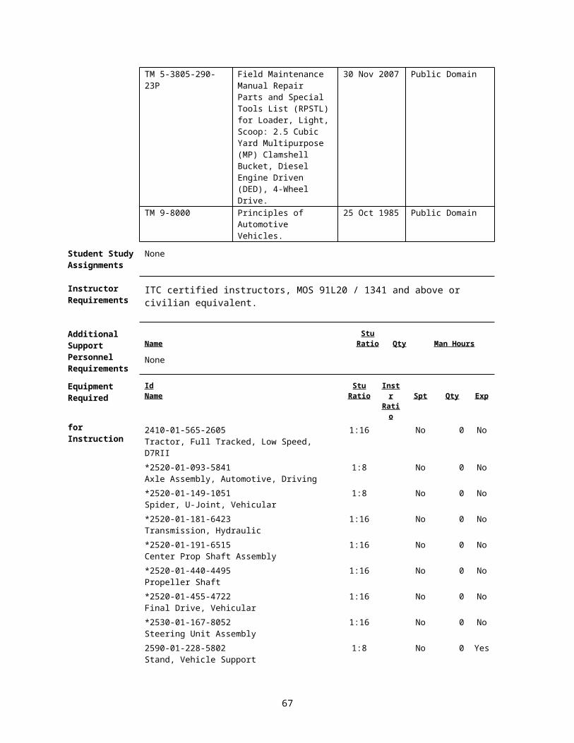
Final Drives91L10E04 / Version 1
01 Oct 2009
SECTION I. ADMINISTRATIVE DATA
All Courses Including This Lesson
Course Number Version Course Title612-91L10 1 Construction Equipment Repairer612-91L10 2 Construction Equipment Repairer (DRAFT)612-91T10 1 Construction Equipment Repairer (DRAFT)
Task(s)Taught(*) orSupported
Task Number Task Title
INDIVIDUAL 091-62B-1507 (*) Replace a Final Drive on an Item of Construction Equipment091-62B-1509 (*) Repair Steering Brakes and Clutches on an Item of
Construction Equipment091-62B-1701 (*) Replace a Track on an Item of Construction Equipment091-62B-1702 (*) Repair a Track Assembly on an Item of Construction
Equipment.
Reinforced Task(s)
Task Number Task Title
Academic Hours
The academic hours required to teach this lesson are as follows:
ResidentHours/Methods
1 hr 10 mins / Conference / Discussion1 hr 10 mins / Demonstration
8 hrs / Practical Exercise (Performance)Test 0 hrsTest Review 0 hrs
Total Hours: 10 hrs 20 mins
Test Lesson Number
Hours Lesson No.
Testing(to include test review) N/A
Prerequisite Lesson(s)
Lesson Number Lesson Title91L10A01 Course Introduction91L10A02 Shop Safety Procedures91L10A03 Environmental Awareness Procedures91L10A04 Identify Computer Software and Hardware Components91L10A05 AKO Procedures91L10A06 Troubleshooting Logic Tree91L10A07 The Levels of Maintenance and Their Responsibility91L10A08 Utilize Maintenance and Repair Parts Technical
Manuals 91L10A09 Utilize Maintenance Forms and Records91L10A10 Battlefield Damage Assessment and Repair (BDAR)91L10A11 Identify Items of Construction Equipment91L10A12 Identify Test, Measurement and Diagnostic Equipment
(TMDE), general mechanics and special tools.91L10A13 Shop Operations Examination
67
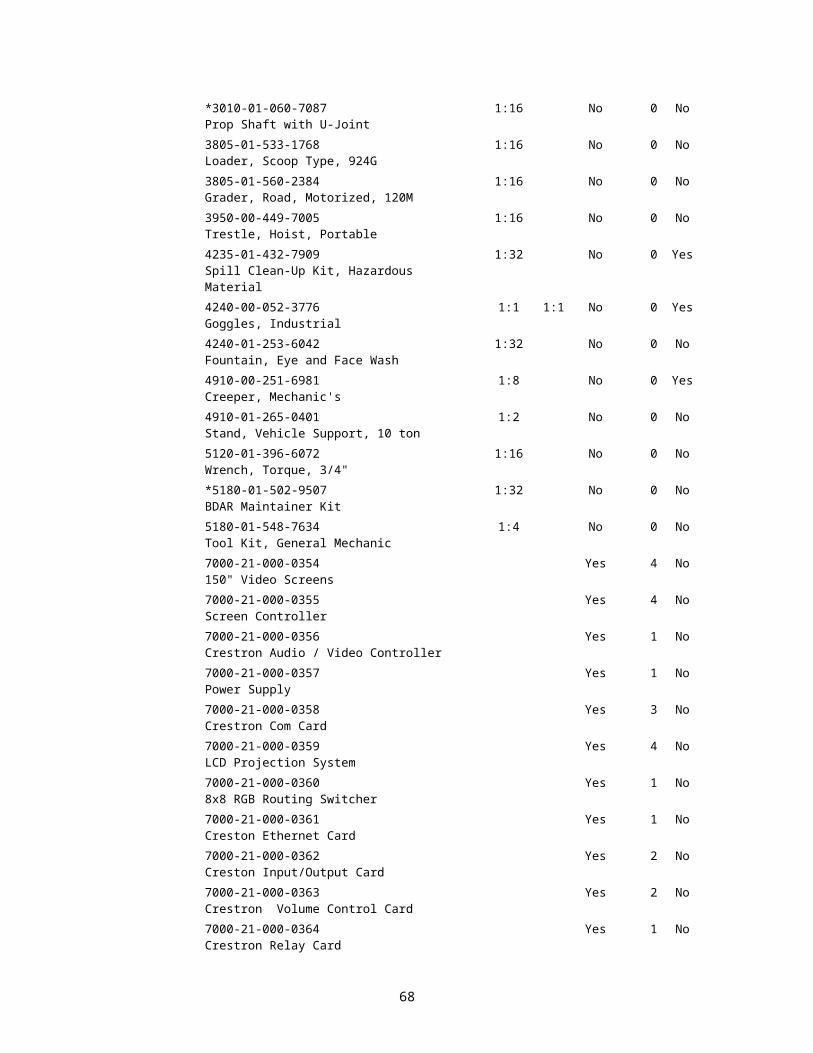
91L10B01 The Fundamentals of Electricity91L10B02 Wiring Diagrams, Schematics, and Automotive
Batteries. 91L10B03 Identify Test, Measurement and Diagnostic Equipment
(TMDE)91L10B04 Starting and Charging Systems91L10B05 Electrical Systems Examination91L10C01 Diesel Engine Principles91L10C02 Disassembly/Assembly of a Diesel Engine 91L10C03 Diesel Engine Component Replacement Performance
Evaluation91L10C04 Diesel Engine Systems Written Examination91L10C05 Diesel Engine Test and Adjustment Procedures91L10C06 Diesel Engine Systems Performance Evaluation91L10D01 Hydraulic System Fundamentals91L10D02 Hydraulic Cylinders and Lines91L10D03 Hydraulic Pumps and Control Valves91L10D04 Hydraulic Accumulators91L10D05 Hydraulic Schematics91L10D06 Hydraulic Systems Examination91L10E01 Power Train Gears, Bearings and Seals91L10E02 Torque Converters, Transmissions, Planetary Gears and
Clutches91L10E03 Differentials and Axles
Clearance Access
Security Level: UnclassifiedRequirements: There are no clearance or access requirements for the lesson.
Foreign Disclosure Restrictions
FD5. This product/publication has been reviewed by the product developers in coordination with the Fort Leonard Wood, MO / Maneuver Support Center foreign disclosure authority. This product is releasable to students from all requesting foreign countries without restrictions.
68

ReferencesNumber Title Date
Additional Information
29 CFR 1910.1200 Hazard Communication 01 Jul 200329 CFR 1910.132 Personnel Protective
Equipment - General Requirements
01 Jul 2003
29 CFR 1910.133 Eye and Face Protection 01 Jul 200329 CFR 1910.136 Foot Protection 01 Jul 200329 CFR 1910.138 Hand Protection 01 Jul 200329 CFR 1910.147 The Control of
Hazardous Energy (Lockout/Tagout).
01 Jul 2003
29 CFR 1910.95 Occupational Noise Exposure
01 Jul 2003
AR 385-10 The Army Safety Program
23 Aug 2007
EM 385-1-1 Safety and Health Requirements.
03 Nov 2003 Public Domain
FM 3-100.4 Environmental Considerations in Military Operations. MCRP 4-11B
15 Jun 2000 Public Domain
FM 5-19 (FM 100-14) Composite Risk Management.
21 Aug 2006 Public Domain
TM 5-2350-262-20-1 Unit Maintenance Manual Vol 1 of 3 for Armored Combat Earthmover (ACE), M9 (NSN 2350-00-808-7100).
03 Jan 1997 EM 0035; Public Domain
TM 5-2350-262-20-2 Unit Maintenance Manual, Vol 2 of 3 for Armored Combat Earthmover (ACE), M9 (NSN 2350-00-808-7100).
03 Jan 1997 EM 0035; Public Domain
TM 5-2410-237-23 Unit and Direct Support Maintenance for Tracker, Full Tracked, Low Speed: Diesel Engine Driven, Medium Drawbar Pull Tractor with Ripper, Tractor With Winch, Tractor With Ripper and Winterized Cab, Tractor With Winch and Winterized Cab...
15 Jul 2005 EM 0119; Public Domain
TM 5-3805-248-23-1 Unit and Direct Support Maintenance for Scraper, Earth Moving, Motorized, Diesel Engine Driven Model 621B (NSN 3805-01-153-1854) (EIC: EH3).
15 Feb 2006 Public Domain
TM 5-3805-248-23-2 Unit and Direct Support Maintenance for Scraper, Earth Moving, Motorized Diesel Engine Driven Model 621B.
15 Feb 2006 Public Domain
Student Study None
69

Assignments
Instructor Requirements
ITC certified instructors, MOS 91L20 / 1341 and above or civilian equivalent.
Additional Support Name
Stu Ratio Qty Man Hours
Personnel Requirements
None
Equipment Required
IdName
Stu Ratio
Instr Ratio Spt Qty Exp
for Instruction 2410-01-223-7261Tractor, Full Tracked, Low Speed, D7G
1:16 No 0 No
*2520-01-093-5841Axle Assembly, Automotive, Driving
1:16 No 0 No
*2520-01-181-6423Transmission, Hydraulic
1:16 No 0 No
*2520-01-440-4495Propeller Shaft
1:16 No 0 No
*2520-01-455-4722Final Drive, Vehicular
1:16 No 0 No
2530-01-075-8292Drift Pin, Track
1:16 No 0 Yes
*2530-01-167-8052Steering Unit Assembly
1:16 No 0 No
2590-01-228-5802Stand, Vehicle Support
1:8 No 0 Yes
3805-01-153-1854Scraper, Tractor
1:16 No 0 No
3950-01-007-0781Crane, Floor, Portable, 4000 lb Capacity
1:16 No 0 No
4235-01-432-7909Spill Clean-Up Kit, Hazardous Material
1:32 No 0 Yes
4240-00-052-3776Goggles, Industrial
1:1 1:1 No 0 Yes
4240-01-253-6042Fountain, Eye and Face Wash
1:32 No 0 No
4930-00-253-2478Lubricating Gun, Hand
1:8 No 0 Yes
5120-00-204-1999Wrench Set, Socket 3/4 Inch Drive
1:8 No 0 No
5120-00-251-4489Hammer, Hand
1:16 No 0 No
5120-00-640-6364Wrench, Torque 175 FT-LB
1:8 No 0 No
*5180-01-502-9507BDAR Maintainer Kit
1:32 No 0 No
5180-01-548-7634Tool Kit, General Mechanic
1:4 No 0 No
6230-00-146-8898Light, Extension
1:8 No 0 Yes
*62B10E01V1Crawler Undercarriage Introduction, Part 1 (Video Film)
1:32 No 0 No
70
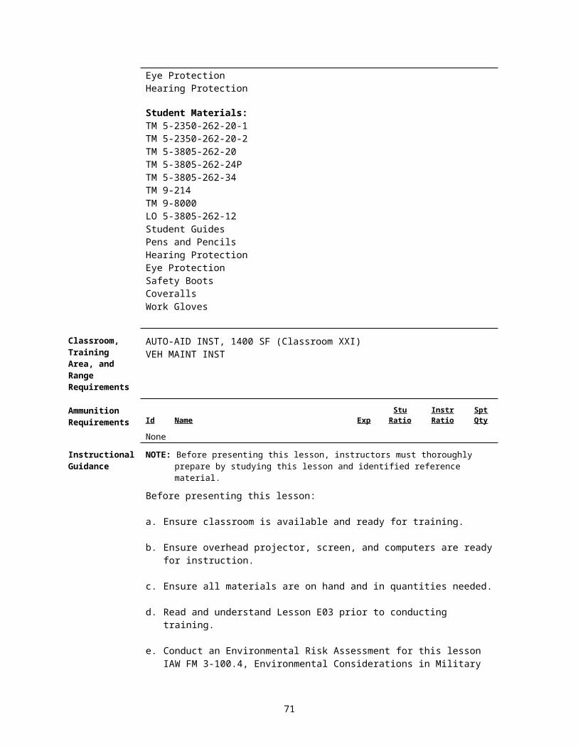
*62B10E01V2Crawler Undercarriage Wear, Part 2 (Video Film)
1:32 Yes 0 No
7000-21-000-0354150" Video Screens
Yes 4 No
7000-21-000-0355Screen Controller
Yes 4 No
7000-21-000-0356Crestron Audio / Video Controller
Yes 1 No
7000-21-000-0357Power Supply
Yes 1 No
7000-21-000-0358Crestron Com Card
Yes 3 No
7000-21-000-0359LCD Projection System
Yes 4 No
7000-21-000-03608x8 RGB Routing Switcher
Yes 1 No
7000-21-000-0361Creston Ethernet Card
Yes 1 No
7000-21-000-0362Creston Input/Output Card
Yes 2 No
7000-21-000-0363Crestron Volume Control Card
Yes 2 No
7000-21-000-0364Crestron Relay Card
Yes 1 No
7000-21-000-0365Crestron RS-232/IR Control Card
Yes 1 No
7000-21-000-0366Crestron Infrared Transmitter
Yes 2 No
7000-21-000-0367Ceiling Speaker System
Yes 16 No
7000-21-000-0368Crestron Lighting Controller
Yes 2 No
7000-21-000-0369Crestron 12" Video Touch Panel
Yes 2 No
7000-21-000-0385Projector Mounting System
Yes 4 No
7000-21-000-0386Audio Power Amplifier
Yes 4 No
7000-21-000-0387Headset Microphone
Yes 2 No
7000-21-000-0388Condenser Microphone
Yes 2 No
7000-21-000-0389Microphone Base
Yes 2 No
7000-21-000-0390Power Conditioner
Yes 2 No
7000-21-000-03918x8 Audio Video Routing Switcher
Yes 1 No
7000-21-000-0392VCR / DVD Player
Yes 2 No
7000-21-000-0393VCR / DVD Control Module
Yes 2 No
7000-21-000-0394Wireless Microphone System
Yes 2 No
71
7000-21-000-0395Lavaliere Microphone
Yes 2 No
7000-21-000-0396Audio Dynamics Processor
Yes 1 No
7000-21-000-0397Microphone Mixer
Yes 2 No
7000-21-000-0398Audio Routing Mixer
Yes 1 No
7000-21-000-039920 Space Security Door
Yes 1 No
7000-21-000-04002-Space Vented Security Panel
Yes 2 No
7000-21-000-0401Document Camera
Yes 2 No
7000-21-000-0402Wireless Mouse
Yes 2 No
7000-21-000-04031x2 RGB Distribution Amplifier
Yes 2 No
7000-21-000-0404Audio/Video/Control Cable and Assemblies
Yes 2 No
7000-21-000-0405Control System Design
Yes 40 No
7000-21-000-0406Smart Board Display Monitor
Yes 40 No
7000-21-000-0407Documentation for Installation Schematics
Yes 10 No
7000-21-000-0408Rack
Yes 10 No
7000-21-000-0409Instructor PC
Yes 2 No
7110-01-202-3674Board, Marker, Dry, Erasable Type
1:1 No 0 No
7195-00-477-5699Stand, Lecture
1:1 No 0 No
8405-00-131-6508Coveralls, Men's OG 46M
1:1 Yes 0 No
8415-00-268-7868Gloves, Work, Men's and Women's
1:1 Yes 0 No
8430-00-624-3135Boots, Safety, Men's, Size 10 Regular
1:1 Yes 0 No
8435-01-475-6874Boots, Safety, Women's, Size 8 Regular
1:1 Yes 0 No
9140-00-286-5295Diesel Fuel, 5 gallon
1:32 No 0 Yes
9150-01-197-7693Grease, Automotive and Artillery
1:32 No 0 Yes
* Before Id indicates a TADSS
Materials Required
Instructor Materials: TM 5-2350-262-20-1TM 5-2350-262-20-2TM 5-2410-237-23TM 5-3805-248-23-1TM 5-3805-248-23-2
72

TM 9-214TM 9-8000FOS 40FOS 54POL29 CFR 1910.1200 Hazard Communication 01 Jul 200329 CFR 1910.132 Personnel Protective 01 Jul 2003
Equipment –General Requirements
29 CFR 1910.133 Eye and Face Protection 01 Jul 200329 CFR 1910.136 Foot Protection 01 Jul 200329 CFR 1910.138 Hand Protection 01 Jul 200329 CFR 1910.95 Occupational Noise 01 Jul 2003
ExposureHearing ProtectionEye Protection
Student Materials: TM 5-2350-262-20-1TM 5-2350-262-20-2TM 5-2410-237-23TM 5-3805-248-23-1TM 5-3805-248-23-2TM 9-214TM 9-8000Student GuidesPens and PencilsHearing ProtectionEye ProtectionSafety BootsCoveralls
Classroom, Training Area, and Range Requirements
AUTO-AID INST, 1400 SF (Classroom XXI)VEH MAINT INST
Ammunition Requirements Id Name Exp
Stu Ratio
Instr Ratio
Spt Qty
None
Instructional Guidance
NOTE: Before presenting this lesson, instructors must thoroughly prepare by studying this lesson and identified reference material.
Before presenting this lesson:
a. Ensure classroom is available and ready for training.
b. Ensure overhead projector, screen, and computers are ready for instruction.
c. Ensure all materials are on hand and in quantities needed.
d. Read and understand Lesson E04 prior to conducting training.
e. Conduct an Environmental Risk Assessment for this lesson IAW FM 3-100.4, Environmental Considerations in Military Operations.
73
1) The assessment is to be recorded on the Risk Management Worksheet found in appendix F of FM 3-100.4. FM 5-19, Composite Risk Management, has more information on this worksheet.
2) During the assessment instructors should look for environmental hazards including all activities that may pollute, generate hazardous or solid waste, create negative noise-related effect, degrade archaeological, cultural resources, or negatively affect threatened or endangered species’ habitats.
3) Ensure instructor check Contemporary Operational Environment web site for latest updates.
https://sp.wood.army.mil/sites/Manscen/ENG/1bde/169/ACO2/COA/Tab4.aspx
f. In accordance with AR 385-10, Army Safety Program, Chapter 16, Occupational Safety and Health Program (Workplace Safety):
1) OSHA programs and national consensus standards shall be applicable to and integrated into all Army equipment, systems, operations, and workplaces, CONUS and OCONUS.
2) Military design, specifications, and deployment requirements will comply with OSHA standards where feasible. When no standard exists for military application or the application is not feasible, the Army component will apply mishap risk management component of CRM.
3) Military and Army civilian officials at each management level shall promote strong safety programs, safe working conditions, and safe performance to prevent accidents, injuries, and occupational illnesses.
Proponent Lesson Plan Approvals
Name
Shankland, Steven
Rank
SSG
Position
Developer/Writer
Date
27 Dec 2007
King, Ronnie YC-02 Chief, Construction Engineer Branch
27 Dec 2007
Rutledge, Jesse YC-02 Chief, Individual Training Division
27 Dec 2007
SECTION II. INTRODUCTION
Method of Instruction: Conference / Discussion Instructor to Student Ratio is: 1:32 Time of Instruction: 5 mins Media: Large Group Instruction
Motivator NOTE: Show Slide #1, Introduction
a. Introduction of the instructor and topic of instruction.
b. State complete action, condition, standards, safety, and environmental
74

considerations.
NOTE: Show Slide #2, TLO
c. Explain the importance of being able to identify, troubleshoot, repair and replace final drives and final drive components.
Terminal Learning Objective
NOTE: Inform the students of the following Terminal Learning Objective requirements.
At the completion of this lesson, you [the student] will:
Action: Identify final drive, steering clutch, undercarriage components, and their functions.
Conditions: In a contemporary operational environment, given items of construction equipment, training aids, a general mechanics tool kit, special tools, TMDE, PPE, TM 9-8000, TM 5-2410-237-23, TM 5-2350-262-10 & 20, TM 5-3805-248-23-1 & 23-2 and TM 5-3805-262-20 & 34.
Standards: Identify, locate, and adjust/replace steering clutch, final drive and undercarriage components on an item of construction equipment or training aid. Perform all operations without damage to equipment or injury to personnel.
Safety Requirements
There is a possibility of injury while lifting heavy objects during this lesson. Use proper lifting techniques and use lifting devices. Remove all jewelry to include ID tags and wedding bands when working on equipment. Use caution around moving parts. You will wear eye and foot protection when required by the instructor, while working around equipment. You will be provided and required to wear aural protectors while equipment is in operation. Follow all safety procedures. The use of Personal protective Equipment (PPE) by students and instructors is mandatory. Further guidance concerning PPE can be found in OSHA regulations 29 CFR 1910.132; 29 CFR 1910.133; 29 CFR 1910.136; 29 CFR 1910.138; and 29 CFR 1910.95.
Risk Assessment Level
Medium - The risk assessment for this module has been reviewed and signed by the responsible officer. Review the deliberate risk assessment, perform a daily risk assessment, and ensure it is recorded on appropriate forms, signed by authorized command authority, and posted at the training site.
Environmental Considerations
NOTE: It is the responsibility of all Soldiers and DA civilians to protect the environment from damage.There is a possibility of environmental contamination by Petroleum, Oil and Lubricants (POL), fuel, and cleaning solvents. You will be briefed on the proper disposal of POL products and how to properly clean up spills prior to each practical exercise. Ensure spill kits are available and there location identified. Instructors should complete a risk assessment before conducting training, operations, or logistical activities. Risk assessments assist instructors in identifying potential environmental hazards, develop controls, make risk decisions, implement controls, and ensure proper supervision and evaluation.
75

Evaluation Practical Exercise
Instructional Lead-In
NOTE: Show Slide #1
NOTE: Introduce the lessons contained in this TSP.
SECTION III. PRESENTATION
1. Learning Step / Activity 1. Identify steering clutch and final drive components.
Method of Instruction: Conference / DiscussionInstructor to Student Ratio: 1:32
Time of Instruction: 25 minsMedia: Large Group Instruction
NOTE: Contemporary Operational Environment
At various times during the class, the instructor will stress the importance of the topic by conveying personal experience related to the topic of discussion. The instructor will also answer any questions relating to the experience.
NOTE: Show Slide #3
a. In your previous instruction you learned about differentials and axles and how they transmit power to the wheels. Now you will learn how that same power is transmitted to the tracks or wheels on construction equipment by way of the final drive. The final drive creates the largest amount of torque increase which construction equipment requires in order to move heavy loads.
b. Power Flow.
The power flows from the engine, through the torque converter and the transmission, to the bevel gear. The power then flows through the steering clutch where it can be controlled before ending at the final drive assembly.
NOTE: Show Slide #4
c. Bevel Gear Assembly.
The power from the engine travels thru the transmission and is then transmitted 90 degrees to each steering clutch assembly by the bevel gear. This is similar to a differential in a wheeled vehicle. The power then moves through the steering clutches to the final drives. The steering clutches, when released, allows the tractor to turn.
NOTE: Show Slide #5
d. Steering Clutch and Brake Assembly.
1) With a steering clutch engaged, the force of the springs keeps the disk assemblies and steel plates against the pressure plate, allowing power to move from the inner drum through the disks to the outer drum (brake drum). The steering clutches are normally engaged.
2) When one steering control lever is pulled back it operates a hydraulic piston, which pushes on the spring retainer compressing the springs. At the same time, the spring retainer pushes on the
76

pressure plate releasing the pressure, which normally keeps the clutch engaged. The steering clutch has now been disengaged allowing the inside track to move independently.
NOTE: Show Slide #6
3) To pivot the tractor, one steering control linkage must be pulled completely to the rear. This will operate the hydraulic piston as explained in the previous slide, disengaging the steering clutch assembly. In addition to the steering clutch being disengaged the control lever operates a hydraulic valve that engages the brake assembly. The brake assembly consists of two band-type brakes that wrap around the brake drum. When engaged, the brake bands make contact with the brake drum, braking the inside track. This allows the tractor to pivot steer.
4) Each track has a steering clutch and brake assembly which operates independently. The brakes can also be controlled by the use of the brake pedals.
NOTE: Show Slide #7
e. Final Drive.
1) The final drive is basically a reduction gear assembly that converts the engine speed into powerful torque, capable of moving extremely heavy loads. The final drive provides the largest amount of torque increase, which allows the other components to carry a relatively light torque load extending the service life of the power train components. Remember, although engine speed is reduced, torque is increased.
NOTE: Show Slide #8
2) Components of the Double Reduction Final Drive.
a) The final drive has two reduction stages. The first stage takes place between the final drive pinion gear and the cluster gear. An idler gear is attached to the cluster gear; so, when the cluster gear turns, the idler gear turns. The second increase takes place between the idler gear and the final drive gear.
b) The D7G uses a dead shaft (a shaft that does not rotate) that only supports the final drive gear and sprocket assemblies.
NOTE: Show Slide #9
c) On the inside and outside of the drive sprocket, there is a set of duo-cone seals that have a metal ring and a rubber o-ring. The metal ring is the part that is the sealing surface while the o-ring holds the seal in place.
d) The bearing cage is the container for the outer tapered bearing which is also connected to the mounting flange.
NOTE: Show Slide #10
f. Final Drive Lubrication System Track-Type Tractor.
A pump lubrication system is used on the D7G’s final drive. Oil is pumped through a passage in the sprocket shaft to lubricate the components within the bearing cage. A ball check valve prevents dirty oil from being pumped out of the filter when the tractor is backing up.
We have been looking at the final drive system of a track-type tractor; now let’s look at the final drive system for a wheeled vehicle.
77

NOTE: Show Slide #11
g. Planetary Final Drive.
1) Wheel loaders, scrapers, and the 25-ton crane feature axle and differential drive systems, but they still require extensive engine speed reduction while increasing torque for driving power. There isn’t much room behind their wheel covers to accommodate a bulky and heavy final drive assembly so planetary gearing is used.
2) The final drive planetary gear system in this final drive is no different than the planetary gear systems found in the power-shift transmission. We will only briefly discuss this type of final drive since you already have a basic concept of the planetary gear system.
a) The ring gear is fastened to the final drive hub, which is fastened to the axle housing.
b) The ring gear is held in a stationary position.
c) Planetary gears are held by the planetary carrier, which is fastened to the wheel assembly.
d) The sun gear is fastened to the axle shaft, which is turned by the differential. The axle shaft provides the power driving the sun gear.
e) The ring gear is held, which makes the planetary gears and planetary carrier walk around in the ring gear.
f) Since the planetary carrier is attached to the hub assembly the power is transmitted to the wheel.
NOTE: Show Slide #12
3) 621B Scraper Power Flow.
The planetary final drive assembly on the 621B Scraper is a little different. Instead of the planetary carrier attaching to the hub assembly, it uses a “Driver” that connects to both the planetary carrier and the hub assembly to transmit the power to the wheels.
NOTE: Show Slide #13
h. Final Drive Lubrication, 621B.
Wheeled vehicle final drives are lubricated through the hub assembly by the splash method.
NOTE: Conduct a check on learning and summarize the learning activity.
Determine if students have learned the material presented by:
1. Soliciting student questions and explanations.
2. Asking questions and receiving answers from the students.
3. Correct student misunderstandings.
78
2. Learning Step / Activity 2. Identify undercarriage components and their functions.
Method of Instruction: Conference / DiscussionInstructor to Student Ratio: 1:32
Time of Instruction: 25 minsMedia: Large Group Instruction
NOTE: Show Slide #14
a. We now move into our next learning activity, the Undercarriage. We will be looking at the undercarriage of the D7G Dozer. The undercarriage is an essential part of the vehicles ability to perform as an earthmover.
NOTE: Show Slide #15
b. Components of the Undercarriage.
1) The components of the undercarriage are the equalizer bar, track rollers, track carrier rollers, tracks front idlers, track roller frames, track adjusters, and recoil springs.
2) The front idlers, track rollers, and track carrier rollers use seals to prevent loss of lubricant and to keep out foreign material.
3) The track roller frames are fastened to the final drive bearing cage and to the steering clutch and bevel gear case. The track rollers, track carrier rollers, tracks, front idlers, track adjusters, and recoil springs are fastened to the track roller frames.
4) The track carrier roller provides the track between the sprocket and the front idler.
5) The track rollers are in contact with the inside of the track links.
6) The front idlers put the tracks in position in front of the track rollers. They also keep the tracks in alignment with the sprockets. The adjustment of the tracks is done with the movement of the front idlers.
NOTE: Show Slide #16
c. The undercarriage connects to the body and final drives. Two track assemblies are kept in parallel alignment by the diagonal brace.
Each track assembly can move up or down by itself
NOTE: Show Slide #17
d. Track Shoe Grousers.
1) The grouser shoes consist of a steel plate with one or more grouser. Depending on the machine application these grousers are different in height and width.
a) The purpose of the grouser is to penetrate the ground and give the machine more traction. b) The shoe, grouser tips and overlap are hardened. The core is softer than the rest of the
material. The softer material provides for flexibility and prevents the material from cracking or breaking. It also provides a base for rebuilding the shoes by welding on new grousers.
79
c) The tracks make direct ground contact, which makes the track-type tractor actually walk.
NOTE: Show Slide #18
2) Track shoes are bolted to the track links.
a) Four bolts and nuts are needed for one shoe on all track-type tractors. The track links are designed that the square nuts are seated in the structure of the link.
b) The track links are sealed and lubricated. They are comprised of links that are connected by bushings, and pins.
NOTE: Show Slide #19
3) The track shoe bolts, naturally, have to be tightened with a torque wrench. Torque specifications are found in the technical manuals.
The bolts need to be retightened periodically to prevent the shoes from coming loose.
NOTE: Show Slide #20
4) The master link is composed of two interlocking parts and is held together by cap screws.
NOTE: Show Slide #21
e. Sprocket Segments.
1) Wear is difficult to measure. Use the sprocket gauge to measure wear to determine if you need to replace any teeth segments. The segments are tempered like the track shoe, soft core and hardened outside.
2) Teeth segments come in either three or five segments. They can be replaced without removing the track. Remove the rock guard, and then move the vehicle forward until one segment can be unbolted, removed and replaced. Move the vehicle forward again until all segments have been replaced.
NOTE: Show Slide #22
f. Track Guiding and Roller Guards.
Track-type tractors are equipped with track guiding guards. Some, if working in certain ground conditions, can be equipped with track rolling guards.
1) The front and rear of each track roller frame is equipped with guiding guards. These guards
protect the tracks, idlers, sprockets, and rollers from rocks and debris.
a) This protection is considered by many people to be the primary purpose of the track guiding guards.
b) They assist the center flange of the idler in keeping the track links in line.
c) The front guiding guards also receive the track from the idler and hold it in line for the first roller and subsequently all rollers.
2) The track roller guards and center-guiding guards are a continuation of the front and rear guards.
80

a) They hold the track in line between the rollers when uneven surfaces under the track shoes tend to push the rails out of line when the machine is turning.
b) They also extend the track life when the machine is working in rock.
NOTE: Show Slide #23
g. Track Adjusters.
1) Every track-type tractor is equipped with two track adjusters, one for each track. They are mounted on top of the track roller frame behind the idler.
2) There are two types of track adjusters used: hydraulic track adjusters on large machines and mechanical track adjusters used on small machines.
a) The purpose of the adjusters is to tighten or to loosen the tracks. They also have to maintain correct track tension to compensate for track wear.
b) The adjusting mechanism consists of the following components: A cylinder bolted to the piston rod, which connects to the yoke assembly and idler. The cylinder flange contains two valve assemblies, one fill valve and one relief valve. Inside the cylinder is a piston. Between the piston and the base of the front pilot is a sleeve. In front of the piston, where the cylinder is connected to the recoil rod, is a cavity. This cavity is filled with oil or grease.
NOTE: Show Slide #24
3) The cylinder flange contains two valve assemblies, one fill valve and one relief valve.
4) Track adjustment is made by adding grease to the cavity through the fill valve. This moves the recoil rod and the front idler toward the front of the machine. The movement of the recoil rod and front idler tightens the track. The tension on the track is released by a relief valve.
NOTE: Show Slide #25
5) The adjusters consist of a yoke assembly, which is connected to the idler bearing housing. Connected to the yoke is the recoil rod. The rod has a flange that is bolted to a cylinder assembly. The cylinder assembly is part of the track adjusting mechanism. It extends into the recoil spring assembly, which is mounted between two stops on the track roller frame and is normally in compression. The force of the springs is not against the track. The force against the track for setting of the track curve (sag) is controlled by the track adjuster.
6) If rocks or debris get between the track and the rollers, idler or sprocket, the recoil rod moves toward the rear of the machine. The movement of the recoil rod tightens the track. Since the grease in the cavity cannot be put in compression, the piston and bolt move toward the rear of the machine. The bolt pushes the pilot toward the rear of the machine. The Pilot pushes on the spring. This puts the spring in compression. The movement of the pilot and the compression of the spring prevent too much tension on the track. A nut is used to keep the spring in compression when it is installed in the machine.
NOTE: Show Slide #26
7) Adjusting the track is important to maintain long life of track components.
8) The track on the D7G dozer must be adjusted to the terrain it is working on. The vehicle must be operated for a short period of time in the terrain and then the track must be adjusted. This is to
81

allow for earth materials that will pack into the track assembly and over tighten the track. Each time the vehicle is moved to a new type of terrain the tracks must be adjusted.
9) When adjusting the track do not use a compressed air grease gun to adjust the track. Blown seals will result.
NOTE: Conduct a check on learning and summarize the learning activity.
Determine if students have learned the material presented by:
1. Soliciting student questions and explanations.
2. Asking questions and receiving answers from the students.
3. Correct student misunderstandings.
3. Learning Step / Activity 3. Observe the operation of final drive components.
Method of Instruction: DemonstrationInstructor to Student Ratio: 1:16
Time of Instruction: 30 minsMedia: Training Aid
Instructor will demonstrate the operation of the final drives ensuring students understand the operation of single reduction and double reduction final drives. Instructor will show the power flow from the driving axles thru the steering clutches and into the final drive.
NOTE: Conduct a check on learning and summarize the learning activity.
Determine if students have learned the material presented by:
1. Soliciting student questions and explanations.
2. Asking questions and receiving answers from the students.
3. Correct student misunderstandings.
4. Learning Step / Activity 4. Observe the configuration and function of undercarriage components
Method of Instruction: DemonstrationInstructor to Student Ratio: 1:16
Time of Instruction: 30 minsMedia: Training Aid
Instructors will show and describe the undercarriage components and there function with special attention paid to the dozer and how the dozer rides on its suspension. Instructors will also point out the front and rear rock guards and how they wear faster then the center section rock guards. Instructors will also point out all rollers carriers and sprockets and how they wear.
82

NOTE: Conduct a check on learning and summarize the learning activity.
Determine if students have learned the material presented by:
1. Soliciting student questions and explanations.
2. Asking questions and receiving answers from the students.
3. Correct student misunderstandings.
5. Learning Step / Activity 5. Implement final drive component repair, replacement and adjustments.
Method of Instruction: Practical Exercise (Performance)Instructor to Student Ratio: 1:4
Time of Instruction: 8 hrs Media: Training Aid
Practical Exercise Instructions.
a. Give detailed instructions on what is expected during the practical exercise IAW Appendix C.
b. Ensure students have required materials and references IAW Appendix C.
c. Clarify students’ questions.
d. Conduct the practical exercise IAW Appendix C.
e. Check on students’ progress and provide assistance as necessary throughout the exercise.
f. Ensure students’ complete the practical exercise within the allotted time.
g. Provide solutions to the practical exercise.
NOTE: Conduct a check on learning and summarize the learning activity.
SECTION IV. SUMMARY
Method of Instruction: Conference / Discussion Instructor to Student Ratio is: 1:32 Time of Instruction: 5 mins Media: Large Group Instruction
Check on Learning
Determine if the students have learned the material presented by soliciting student questions and explanations. Ask the students questions and correct misunderstandings.
Review / Summarize Lesson
Restate the Terminal Learning Objective (TLO) (Identify differential and axle components and their functions). Summarize the Learning Steps/Activities.
1. Identify differential and axle components and their functions.
83

2. Observe conventional and no-spin differential operation.
3. Implement differential and axle troubleshooting, repair, replacement, and adjustment.
84
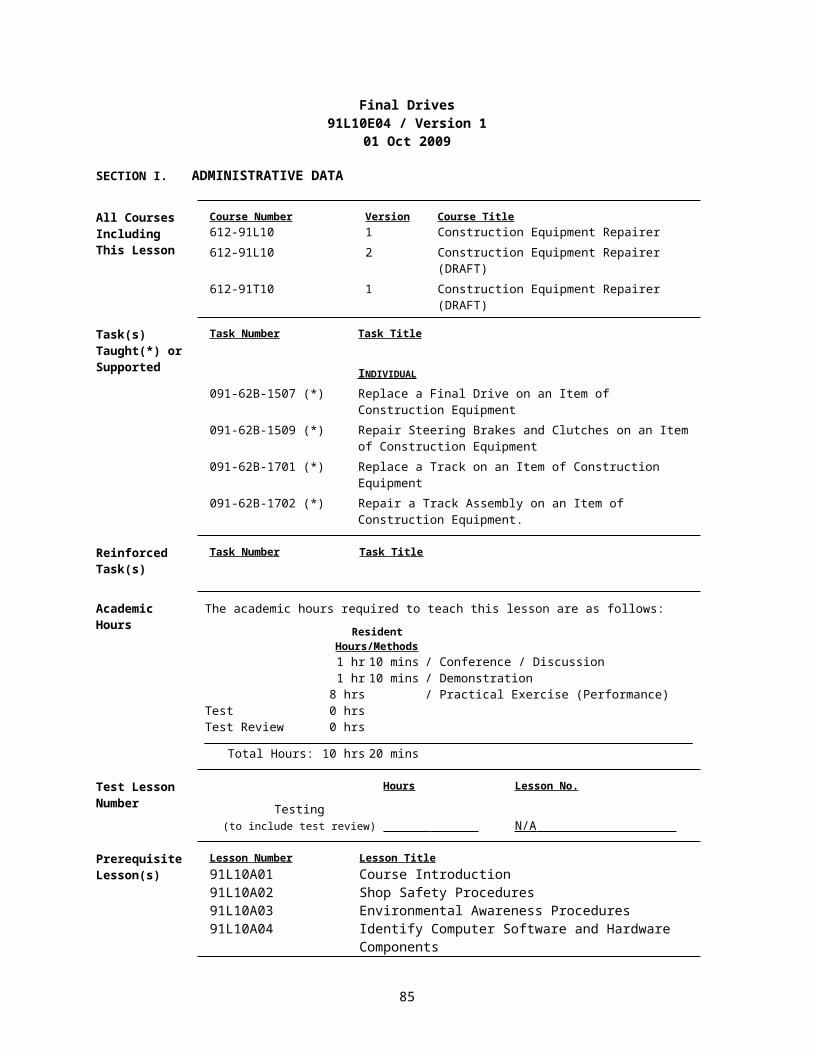
SECTION V. STUDENT EVALUATION
Testing Requirements
NOTE: Describe how the student must demonstrate accomplishment of the TLO. Refer student to the Student Evaluation Plan.
Feedback Requirements
NOTE: Feedback is essential to effective learning. Schedule and provide feedback on the evaluation and any information to help answer students' questions about the test. Provide remedial training as needed.
85

Power Train Systems Examination91L10E05 / Version 1
01 Oct 2009
SECTION I. ADMINISTRATIVE DATA
All Courses Including This Lesson
Course Number Version Course Title612-91L10 1 Construction Equipment Repairer612-91L10 2 Construction Equipment Repairer (DRAFT)612-91T10 1 Construction Equipment Repairer (DRAFT)
Task(s)Taught(*) orSupported
Task Number Task Title
INDIVIDUAL 091-62B-1502 (*) Replace a Driveshaft on an Item of Construction Equipment091-62B-1507 (*) Replace a Final Drive on an Item of Construction Equipment091-62B-1509 (*) Repair Steering Brakes and Clutches on an Item of
Construction Equipment091-62B-1702 (*) Repair a Track Assembly on an Item of Construction
Equipment.
Reinforced Task(s)
Task Number Task Title
Academic Hours
The academic hours required to teach this lesson are as follows:
ResidentHours/Methods
10 mins / Conference / DiscussionTest 6 hrs 15 minsTest Review 30 mins
Total Hours: 7 hrs 5 mins
Test Lesson Number
Hours Lesson No.
Testing(to include test review) N/A
Prerequisite Lesson(s)
Lesson Number Lesson Title91L10A01 Course Introduction91L10A02 Shop Safety Procedures91L10A03 Environmental Awareness Procedures91L10A04 Identify Computer Software and Hardware Components91L10A05 AKO Procedures91L10A06 Troubleshooting Logic Tree91L10A07 The Levels of Maintenance and Their Responsibility91L10A08 Utilize Maintenance and Repair Parts Technical
Manuals 91L10A09 Utilize Maintenance Forms and Records91L10A10 Battlefield Damage Assessment and Repair (BDAR)91L10A11 Identify Items of Construction Equipment91L10A12 Identify Test, Measurement and Diagnostic Equipment
(TMDE), general mechanics and special tools.91L10A13 Shop Operations Examination91L10B01 The Fundamentals of Electricity91L10B02 Wiring Diagrams, Schematics, and Automotive
86

Batteries. 91L10B03 Identify Test, Measurement and Diagnostic Equipment
(TMDE)91L10B04 Starting and Charging Systems91L10B05 Electrical Systems Examination91L10C01 Diesel Engine Principles91L10C02 Disassembly/Assembly of a Diesel Engine 91L10C03 Diesel Engine Component Replacement Performance
Evaluation91L10C04 Diesel Engine Systems Written Examination91L10C05 Diesel Engine Test and Adjustment Procedures91L10C06 Diesel Engine Systems Performance Evaluation91L10D01 Hydraulic System Fundamentals91L10D02 Hydraulic Cylinders and Lines91L10D03 Hydraulic Pumps and Control Valves91L10D04 Hydraulic Accumulators91L10D05 Hydraulic Schematics91L10D06 Hydraulic Systems Examination91L10E01 Power Train Gears, Bearings and Seals91L10E02 Torque Converters, Transmissions, Planetary Gears and
Clutches91L10E03 Differentials and Axles91L10E04 Final Drives
Clearance Access
Security Level: UnclassifiedRequirements: There are no clearance or access requirements for the lesson.
Foreign Disclosure Restrictions
FD5. This product/publication has been reviewed by the product developers in coordination with the Fort Leonard Wood, MO / Maneuver Support Center foreign disclosure authority. This product is releasable to students from all requesting foreign countries without restrictions.
87

ReferencesNumber Title Date
Additional Information
29 CFR 1910.1200 Hazard Communication 01 Jul 200329 CFR 1910.132 Personnel Protective
Equipment - General Requirements
01 Jul 2003
29 CFR 1910.133 Eye and Face Protection 01 Jul 200329 CFR 1910.136 Foot Protection 01 Jul 200329 CFR 1910.138 Hand Protection 01 Jul 200329 CFR 1910.147 The Control of
Hazardous Energy (Lockout/Tagout).
01 Jul 2003
29 CFR 1910.95 Occupational Noise Exposure
01 Jul 2003
AR 385-10 The Army Safety Program
23 Aug 2007
EM 385-1-1 Safety and Health Requirements.
03 Nov 2003 Public Domain
FM 3-100.4 Environmental Considerations in Military Operations. MCRP 4-11B
15 Jun 2000 Public Domain
FM 5-19 (FM 100-14) Composite Risk Management.
21 Aug 2006 Public Domain
TM 5-2410-237-23 Unit and Direct Support Maintenance for Tracker, Full Tracked, Low Speed: Diesel Engine Driven, Medium Drawbar Pull Tractor with Ripper, Tractor With Winch, Tractor With Ripper and Winterized Cab, Tractor With Winch and Winterized Cab...
15 Jul 2005 Public Domain
TM 5-3805-248-23-1 Unit and Direct Support Maintenance for Scraper, Earth Moving, Motorized, Diesel Engine Driven Model 621B (NSN 3805-01-153-1854) (EIC: EH3).
15 Feb 2006 Public Domain
TM 5-3805-248-23-2 Unit and Direct Support Maintenance for Scraper, Earth Moving, Motorized Diesel Engine Driven Model 621B.
15 Feb 2006 Public Domain
TM 5-3805-290-23-1 Field Maintenance Manual for Loader, Light, Scoop; 2.5 Cubic Yard Multipurpose (MP) Clamshell Bucket, Diesel Engine Driven (DED), 4-Wheel Drive.
30 Nov 2007 Public Domain
88

TM 5-3805-290-23-2 Field Maintenance Manual for Loader, Light, Scoop: 2.5 Cubic Yard Clamshell Bucket, Diesel Engine Driven (DED), 4-Wheel Drive Caterpillar Model 924G.
30 Nov 2007 Public Domain
TM 9-8000 Principles of Automotive Vehicles.
25 Oct 1985 Public Domain
Student Study Assignments
None
Instructor Requirements
ITC certified instructors, MOS 91L20 / 1341 and above or civilian equivalent.
Additional Support Name
Stu Ratio Qty Man Hours
Personnel Requirements
None
Equipment Required
IdName
Stu Ratio
Instr Ratio Spt Qty Exp
for Instruction 2410-01-223-7261Tractor, Full Tracked, Low Speed, D7G
1:16 No 0 No
*2520-01-093-5841Axle Assembly, Automotive, Driving
1:4 No 0 No
*2520-01-440-4495Propeller Shaft
1:16 No 0 No
*2520-01-455-4722Final Drive, Vehicular
1:16 No 0 No
2590-01-228-5802Stand, Vehicle Support
1:8 No 0 Yes
3805-01-153-1854Scraper, Tractor
1:16 No 0 No
3805-01-533-1768Loader, Scoop Type, 924G
1:16 No 0 No
3950-00-449-7005Trestle, Hoist, Portable
1:16 No 0 No
3950-01-007-0781Crane, Floor, Portable, 4000 lb Capacity
1:16 No 0 No
4235-01-432-7909Spill Clean-Up Kit, Hazardous Material
1:32 No 0 Yes
4240-00-022-2946Protector, Hearing
1:1 1:1 No 0 Yes
4240-00-052-3776Goggles, Industrial
1:1 1:1 No 0 Yes
4240-01-253-6042Fountain, Eye and Face Wash
1:32 No 0 No
4910-00-251-6981Creeper, Mechanic's
1:4 No 0 Yes
4910-00-357-5342Table, Work, Automotive Maintenance
1:4 No 0 No
4910-01-265-0401Stand, Vehicle Support, 10 ton
1:2 No 0 No
5120-00-605-3926Fixture, Track Connecting, Full Tracked Vehicle
1:16 No 0 No
89
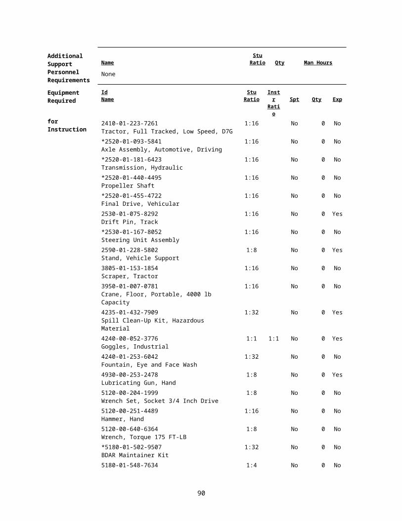
5180-01-548-7634Tool Kit, General Mechanic
1:4 No 0 No
5810-01-523-6682Computer, Laptop, Ruggedized (MIL-STD -810f Compliant), Workstation KG-235
1:4 No 0 No
6230-00-146-8898Light, Extension
1:8 No 0 Yes
7000-21-000-0354150" Video Screens
Yes 4 No
7000-21-000-0355Screen Controller
Yes 4 No
7000-21-000-0356Crestron Audio / Video Controller
Yes 1 No
7000-21-000-0357Power Supply
Yes 1 No
7000-21-000-0358Crestron Com Card
Yes 3 No
7000-21-000-0359LCD Projection System
Yes 4 No
7000-21-000-03608x8 RGB Routing Switcher
Yes 1 No
7000-21-000-0361Creston Ethernet Card
Yes 1 No
7000-21-000-0362Creston Input/Output Card
Yes 2 No
7000-21-000-0363Crestron Volume Control Card
Yes 2 No
7000-21-000-0364Crestron Relay Card
Yes 1 No
7000-21-000-0365Crestron RS-232/IR Control Card
Yes 1 No
7000-21-000-0366Crestron Infrared Transmitter
Yes 2 No
7000-21-000-0367Ceiling Speaker System
Yes 16 No
7000-21-000-0368Crestron Lighting Controller
Yes 2 No
7000-21-000-0369Crestron 12" Video Touch Panel
Yes 2 No
7000-21-000-0385Projector Mounting System
Yes 4 No
7000-21-000-0386Audio Power Amplifier
Yes 4 No
7000-21-000-0387Headset Microphone
Yes 2 No
7000-21-000-0388Condenser Microphone
Yes 2 No
7000-21-000-0389Microphone Base
Yes 2 No
7000-21-000-0390Power Conditioner
Yes 2 No
7000-21-000-03918x8 Audio Video Routing Switcher
Yes 1 No
7000-21-000-0392 Yes 2 No
90

VCR / DVD Player7000-21-000-0393VCR / DVD Control Module
Yes 2 No
7000-21-000-0394Wireless Microphone System
Yes 2 No
7000-21-000-0395Lavaliere Microphone
Yes 2 No
7000-21-000-0396Audio Dynamics Processor
Yes 1 No
7000-21-000-0397Microphone Mixer
Yes 2 No
7000-21-000-0398Audio Routing Mixer
Yes 1 No
7000-21-000-039920 Space Security Door
Yes 1 No
7000-21-000-04002-Space Vented Security Panel
Yes 2 No
7000-21-000-0401Document Camera
Yes 2 No
7000-21-000-0402Wireless Mouse
Yes 2 No
7000-21-000-04031x2 RGB Distribution Amplifier
Yes 2 No
7000-21-000-0404Audio/Video/Control Cable and Assemblies
Yes 2 No
7000-21-000-0405Control System Design
Yes 40 No
7000-21-000-0406Smart Board Display Monitor
Yes 2 No
7000-21-000-0407Documentation for Installation Schematics
Yes 10 No
7000-21-000-0408Rack
Yes 1 No
7000-21-000-0409Instructor PC
Yes 2 No
7110-00-273-8785Chair, Straight
1:1 1:1 No 0 Yes
7110-01-135-1988Table, Office, 60x30x29
1:2 1:1 No 0 Yes
7110-01-202-3674Board, Marker, Dry, Erasable Type
1:1 No 0 No
7125-01-084-6955Cabinet, Storage
1:32 No 0 No
7195-00-477-5699Stand, Lecture
1:1 No 0 No
7510-00-281-5234Pencil
1:1 1:1 No 0 Yes
8405-00-131-6508Coveralls, Men's OG 46M
1:1 Yes 0 No
8415-00-268-7868Gloves, Work, Men's and Women's
1:1 Yes 0 No
8430-00-624-3135Boots, Safety, Men's, Size 10 Regular
1:1 Yes 0 No
8435-01-475-6874 1:1 Yes 0 No
91

Boots, Safety, Women's, Size 8 Regular
* Before Id indicates a TADSS
Materials Required
Instructor Materials: TM 5-2350-262-20-1TM 5-2350-262-20-2TM 5-2410-237-23TM 5-3805-248-23-1TM 5-3805-248-23-2TM 5-3805-262-20TM 5-3805-262-24PTM 5-3805-262-34TM 9-214TM 9-8000FOS 40Caterpillar Dealer Training Course Guide 27Caterpillar Training Guide 33, Basic Power Shift - Planetary GearingCaterpillar Training Guide 44, Basic Power Shift - Torque Converters29 CFR 1910.1200 Hazard Communication 01 Jul 200329 CFR 1910.132 Personnel Protective 01 Jul 2003
Equipment –General Requirements
29 CFR 1910.133 Eye and Face Protection 01 Jul 200329 CFR 1910.136 Foot Protection 01 Jul 200329 CFR 1910.138 Hand Protection 01 Jul 200329 CFR 1910.95 Occupational Noise 01 Jul 2003
ExposureHearing ProtectionEye Protection
Student Materials: TM 5-2350-262-20-1TM 5-2350-262-20-2TM 5-2410-237-23TM 5-3805-248-23-1TM 5-3805-248-23-2TM 5-3805-262-20TM 5-3805-262-24PTM 5-3805-262-34TM 9-214TM 9-8000Student GuidesPens and PencilsHearing ProtectionEye ProtectionSafety BootsCoverallsWork Gloves
Classroom, Training Area, and Range Requirements
AUTO-AID INST, 1400 SF (Classroom XXI)VEH MAINT INST
92

Ammunition Requirements Id Name Exp
Stu Ratio
Instr Ratio
Spt Qty
None
Instructional Guidance
NOTE: Before presenting this lesson, instructors must thoroughly prepare by studying this lesson and identified reference material.
Before presenting this lesson:
a. Ensure classroom is available and ready for training.
b. Ensure overhead projector, screen, and computers are ready for instruction.
c. Ensure all materials are on hand and in quantities needed.
d. Read and understand Lesson E05 prior to conducting training.
e. Conduct an Environmental Risk Assessment for this lesson IAW FM 3-100.4, Environmental Considerations in Military Operations.
1) The assessment is to be recorded on the Risk Management Worksheet found in appendix F of FM 3-100.4. FM 5-19, Composite Risk Management, has more information on this worksheet.
2) During the assessment instructors should look for environmental hazards including all activities that may pollute, generate hazardous or solid waste, create negative noise-related effect, degrade archaeological, cultural resources, or negatively affect threatened or endangered species’ habitats.
3) Ensure instructor check Contemporary Operational Environment web site for latest updates.
https://sp.wood.army.mil/sites/Manscen/ENG/1bde/169/ACO2/COA/Tab4.aspx
f. In accordance with AR 385-10, Army Safety Program, Chapter 16, Occupational Safety and Health Program (Workplace Safety):
1) OSHA programs and national consensus standards shall be applicable to and integrated into all Army equipment, systems, operations, and workplaces, CONUS and OCONUS.
2) Military design, specifications, and deployment requirements will comply with OSHA standards where feasible. When no standard exists for military application or the application is not feasible, the Army component will apply mishap risk management component of CRM.
3) Military and Army civilian officials at each management level shall promote strong safety programs, safe working conditions, and safe performance to prevent accidents, injuries, and occupational illnesses.
93
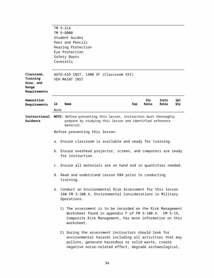
Proponent Lesson Plan Approvals
Name
Shankland, Steven
Rank
SSG
Position
Developer/Writer
Date
27 Dec 2007
King, Ronnie YC-02 Chief, Construction Engineer Branch
27 Dec 2007
Rutledge, Jesse YC-02 Chief, Individual Training Division
27 Dec 2007
SECTION II. INTRODUCTION
Method of Instruction: Conference / Discussion Instructor to Student Ratio is: 1:32 Time of Instruction: 5 mins Media: Large Group Instruction
Motivator NOTE: Show Slide #1, TLO
a. Introduction of the instructor and topic of instruction.
b. State the complete action, condition, standards, safety, and environmental considerations.
c. Stress the importance of passing the written and hands-on evaluation.
Terminal Learning Objective
NOTE: Inform the students of the following Terminal Learning Objective requirements.
At the completion of this lesson, you [the student] will:
Action: Complete a Power Train Systems Examination.
Conditions: In a contemporary operational environment, given items of construction equipment and training aids, technical manuals (TMs) applicable to each item of equipment, TM 9-214, TM 9-8000, a general mechanic’s tool kit, special tools, Test Measurement and Diagnostic Equipment (TMDE), standard shop equipment, petroleum, oils, and lubricants (POL), parts, PPE, a pen and pencil, a test booklet, AIMS answer sheet, and a student guide.
Standards: Identify the fundamentals of power train systems. Identify differential, axle, final drive and power shift transmission components, their functions, test and adjustment points. Perform power train troubleshooting, repair, replacement of faulty components and adjustments without damage to equipment or the environment and without injury to personnel.
Safety Requirements
There is a possibility of injury while lifting heavy objects during this lesson. Use proper lifting techniques and use lifting devices. Remove all jewelry to include ID tags and wedding bands when working on equipment. Use caution around moving parts. You will wear eye and foot protection when required by the instructor, while working around equipment. You will be provided and required to wear aural protectors while equipment is in operation. Follow all safety procedures. The use of Personal protective Equipment (PPE) by students and instructors is mandatory.
94

Further guidance concerning PPE can be found in OSHA regulations 29 CFR 1910.132; 29 CFR 1910.133; 29 CFR 1910.136; 29 CFR 1910.138; and 29 CFR 1910.95.
Risk Assessment Level
Medium - The risk assessment for this module has been reviewed and signed by the responsible officer. Review the deliberate risk assessment, perform a daily risk assessment, and ensure it is recorded on appropriate forms, signed by authorized command authority, and posted at the training site.
Environmental Considerations
NOTE: It is the responsibility of all Soldiers and DA civilians to protect the environment from damage.There is a possibility of environmental contamination by Petroleum, Oil and Lubricants (POL), fuel, and cleaning solvents. You will be briefed on the proper disposal of POL products and how to properly clean up spills prior to each practical exercise. Ensure spill kits are available and there location identified. Instructors should complete a risk assessment before conducting training, operations, or logistical activities. Risk assessments assist instructors in identifying potential environmental hazards, develop controls, make risk decisions, implement controls, and ensure proper supervision and evaluation.
Evaluation Achieve a minimum score of 80% on a written examination in the time allotted and achieve a GO on a performance evaluation in the time allotted. One hour thirty minutes has been allotted for the written examination and five hours has been allotted for the performance evaluation.
Instructional Lead-In
NOTE: Introduce the lessons contained in this TSP.
SECTION III. PRESENTATION
1. Learning Step / Activity 1. Complete a Power Train Systems Written Examination.
Method of Instruction: TestInstructor to Student Ratio: 1:32
Time of Instruction: 1 hr 30 minsMedia: Large Group Instruction
a. Give detailed instructions on test procedures IAW Appendix B.
b. Ensure students have required materials and references IAW Appendix B
c. Clarify students’ questions.
d. Conduct the test IAW Appendix B.
e. Check on students’ progress and provide assistance as necessary during the exam
f. Ensure students turn test booklets and tests in within the allotted time IAW Appendix B
g. Conduct a test review IAW Appendix B.
NOTE: Conduct a check on learning and summarize the learning activity.
95

2. Learning Step / Activity 2. Complete a Power Train Systems Examination Test Review.
Method of Instruction: Test ReviewInstructor to Student Ratio: 1:32
Time of Instruction: 20 minsMedia: Large Group Instruction
a. Test Review.
1) Have students return to the classroom.
2) Explain the purpose of the test review.
b. Conduct a test review IAW Appendix B.
NOTE: Conduct a check on learning and summarize the learning activity.
3. Learning Step / Activity 3. Complete a Power Train Systems Performance Evaluation.
Method of Instruction: TestInstructor to Student Ratio: 1:4
Time of Instruction: 4 hrs 35 minsMedia: Training Aid
a. Give detailed instructions on what is expected during the evaluation IAW Appendix B.
b. Ensure students have required materials and references IAW Appendix B.
c. Clarify students’ questions.
d. Conduct the evaluation IAW Appendix B.
e. Check on students’ progress and provide assistance as necessary throughout the evaluation.
f. Ensure students complete the evaluation within the allotted time IAW Appendix B.
g. Complete student evaluation and review IAW Appendix B.
NOTE: Conduct a check on learning and summarize the learning activity.
4. Learning Step / Activity 4. Complete a Power Train Systems Performance Evaluation Test Review.
Method of Instruction: Test ReviewInstructor to Student Ratio: 1:4
Time of Instruction: 10 minsMedia: Training Aid
NOTE: Conduct a check on learning and summarize the learning activity.
96

SECTION IV. SUMMARY
Method of Instruction: Conference / Discussion Instructor to Student Ratio is: 1:32 Time of Instruction: 5 mins Media: Large Group Instruction
Check on Learning
Determine if the students have learned the material presented by soliciting student questions and explanations. Ask the students questions and correct misunderstandings.
Review / Summarize Lesson
Restate the Terminal Learning Objective (TLO) (Complete a Power Train Systems Examination). Summarize the Learning Steps/Activities.
1. Complete Power Train Systems Written Examination.
2. Complete a Power Train Systems Examination Test Review.
3. Complete a Power Train Systems Performance Evaluation.
4. Complete a Power Train Systems Performance Evaluation Test Review.
97

SECTION V. STUDENT EVALUATION
Testing Requirements
NOTE: Describe how the student must demonstrate accomplishment of the TLO. Refer student to the Student Evaluation Plan.
Feedback Requirements
NOTE: Feedback is essential to effective learning. Schedule and provide feedback on the evaluation and any information to help answer students' questions about the test. Provide remedial training as needed.
98

Appendix A - Viewgraph Masters (N/A)
A-1

Appendix B - Test(s) and Test Solution(s)
TEST QUESTION(S) FOR LESSON 5: 91L10E05 version 1
1. TLO ( 1) [1] Multiple Choice / 1.6 {-}a. Test Administration Procedures.
1) Distribute tests and answer sheets.
2) Inform students not to open test booklet until told to do so.
3) Have students enter their complete names, rank, course, class#, section, date, SSNs, and the exam number on the top of the answer sheet.
4) Inform students of the following:
a) They must achieve a minimum score of 80% on this test. If you fail to receive the minimum score you will be counseled and re-tested. If you pass the retest the highest score you will receive is 80%. If you fail the retest you will be referred to your company commander, recommending restart with another class.
b) On the answer sheet provided, fill in your response to each of the questions contained in the exam.
c) This is an open note, open book test. All course materials can be used.
d) DO NOT WRITE IN THIS TEST BOOKLET.
e) No talking during the examination.
f) Do not begin until told to do so.
g) When you have completed the exam, turn in the test booklet, any scratch paper, and your answer sheet to the instructor. Move to the break area until told to return to the classroom.
5) Ask students if they have any questions pertaining to the test.
6) Give students START and STOP times.
7) Have students begin the test.
8) Ensure a minimum of one instructor is present in classroom during testing.
9) As students finish, collect their test materials and send them to the break area.
10) When time expires, have remaining students immediately stop testing. Collect all test material and send students to the break area.
11) Grade all remaining tests.
b. Conduct a Test Review.
Ask the following questions and allow appropriate time for responses:
1) Was all the test information understood?
B-1

2) Were all the questions on the examination understood?
3) Did the test reflect the contents of the lesson plan and the information taught?
4) Does any portion of the class need more or less time, clarification, or practical exercise?
5) What percentage of students missed any one question? Check each question and clarify as needed.
6) Was the time for the examination adequate?
c. Post the Test Results.
Record each student's performance on the student performance record and maintain in the course office.
2. TLO ( 3) [2] Performance / 4.9 {-}
Test Administration Guide
TSP: 091-E-ITRO Module: Power Trains
Examination Number: 1 Focus Area: Power Trains Performance Evaluation
Test Sites: 4 Testing Period: 5 Hours
Evaluator to Student Ratio: 1 to 4 Students Per Test Site: 1- 2
Task: Correct Power Train System Malfunctions.
Tasks Referenced
Method of Testing Task Title
091-62B-1502 Performance Evaluation Replace a Driveshaft on an Item of Construction Equipment091-62B-1506 Performance Evaluation Replace a Differential on an Item of Construction
Equipment091-62B-1507 Performance Evaluation Replace a Final Drive on Item of Construction Equipment091-62B-1509 Performance Evaluation Repair Steering Brakes and Clutches on an Item of
Construction Equipment
1. Administrative Procedures.
a. Evaluators will prepare the test evaluation sites prior to administering the examination.
Testing sites preparation requirements:
1) Inspect the evaluation site for completeness.
2) Ensure equipment is available and on site.
B-2

QTY Number Title2410-01-223-7261 Tractor, Full Tracked, Low speed, W/ Winch 2520-01-093-5841 Axle Assembly, Automotive, Driving2520-01-440-4495 Propeller Shaft2520-01-455-4722 Final Drive, Vehicular2590-01-228-5802 Stand Vehicle Support3805-01-150-4814 Loader Scoop Type3950-00-449-7005 Trestle, Hoist, Portable3950-01-007-0781 Crane, Floor, Portable, 4000lb Capacity4235-01-432-7909 Spill Clean-up Kit, Hazardous material, Tote Bag
32 EA 4240-00-022-2946 Protector, Hearing32 EA 4240-00-052-3776 Goggles, Industrial
4240-01-253-6042 Fountain, Eye and Face Wash4940-00-251-6981 Creeper, Mechanics4910-00-357-5342 Table, Work, Automotive Maintenance4910-00-754-0705 Shop Equipment, Automotive Vehicle, Basic4910-01-265-0401 Stand, Vehicle Support, 10 Ton5120-00-204-1999 Wrench Set, Socket ¾ Inch Drive5120-00-640-6364 Wrench, Torque, 0-175lbs5120-01-229-9134 Wrench, Spanner5120-01-396-6072 Wrench, Torque, 3/45180-01-454-3787 Tool Kit, General Mechanics6130-01-251-6828 Charger, Battery6230-00-146-8898 Light Extension7110-00-273-8785 Chair, Straight 7110-01-135-1988 Table, Office, 60x30x297110-01-202-3674 Board, Marker, Dry Erasable type7125-01-084-6955 Cabinet, Storage, Flammable7510-01-281-5234 Pencil8145-00-268-7868 Gloves, Work, Men’s and Women’s8430-00-624-3135 Boot’s, Safety, Men’s8435-01-475-6874 Boot’s, Safety, Women’s
B-3
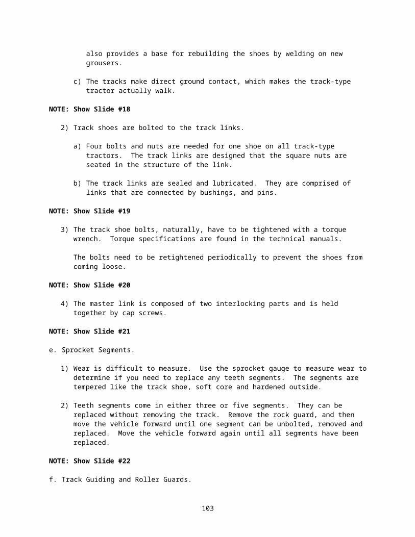
b. Testing site preparation setup:
SITE #1: Adjust Steering Clutch Levers and linkage (D7G).
1) Instructors will insure:
Linkage is out of adjustment.
2) Testing work station will consist of the following items:
a) Tape Measure.
b) Tool box with needed tools.
c) Current Technical Manuals.
d) D7G Dozer.
SITE #2: Adjust D7G Dozer Steering Brakes.
1) Testing Site Preparation.
None.
2) Testing work station will consist of the following items:
a) Tool box with needed tools.
b) Current Technical Manuals.
c) D7G Dozer.
SITE #3: Replace a Final Drive.
1) Testing Site Preparation.
None.
2) Each Test station will consist of the following items:
a) Tool Bag with needed tools.
b) Current Technical Manuals.
c) Lifting Device.
d) Empty can for removed bolts.
SITE #4: Replace a Rear Drive Shaft.
1) Testing Site Preparation.
None.
2) Test work station will consist of the following items:
B-4
a) Tool Box with needed tools.
b) Current Technical Manual.
c) MW24C Loader.
d) Creepers.
e) Work Light.
c. Test Administration Procedures:
1) Explain the importance of passing this test.
2) Inform the students that the complete task will be performed for evaluation regardless if a NO GO is received immediately.
3) Tell students that any safety violation that may cause injury to personnel, or damage to equipment will result in immediate termination of the test and an automatic NO GO for the task.
4) Tell students what tasks will be evaluated.
5) Remind students that the tasks of repairing a clutch assembly, replacing a drive shaft, replacing u-joints, replacing a differential, repairing and replacing a track and repairing a winch brake were evaluated during PEs.
Station One:
Adjust Steering Clutch Linkage on a D7G.
Station Two:
Adjust D7G Steering Brakes.
Station Three:
Replace a Final Drive.
Station Four:
Replace a Rear Drive Shaft.
6) Inform the students of retest policy.
a) Students that fail will be counseled.
b) One retest will be given, and with the commander’s approval, a second retest may be administered.
c) Students will receive additional training prior to retest.
d) Students will receive a retest only on tasks failed.
7) Allow students to ask questions.
B-5

d. Performance Evaluation.
Inform the students the following:
1) Inform students that a GO on all performance measures is required to receive a GO for the action.
2) Inform students that if they find a fault, report it to the instructor for further guidance.
3) Inform students of the time they will have to complete each station.
4) Inform students that there are four stations.
5) Operate the equipment as required for the student.
6) Allow students to ask questions.
7) Have students start the evaluation.
8) Evaluate students’ performance and annotate results on the evaluation checklist.
9) Upon completion of the evaluation, critique students' performance.
10) If student passed, inform him/her of next training location.
11) If student failed, inform him/her of when and where the retraining and retest will be conducted.
12) Allow students to ask questions.
2. Performance Steps.
NOTE: Students will be evaluated on completing the task correctly and in the proper sequence, NOT to time.
SITE #1:
a. The evaluator will complete a briefing on the general procedures and safety governing the administration of the tests.
CAUTION: Inform the students that:
1) The evaluator will explain to the students what the standards are for that site, and assign them to a Dozer.
2) Safety is top priority and will be monitored and enforced throughout this performance exercise. Use hearing and eye protection when needed. Use correct lifting procedures and adhere to all safety warnings, cautions, notes, and from instructors. Any safety violation will result in immediate termination of the test and a NO-GO.
b. This test was designed to measure your knowledge of Power Trains. You will be assigned a work station, with needed tools, a problem, and a Technical Manual. The performance exercise at this station will be 15 minutes, and you will be tested individually.
SITE #2:
B-6
a. The evaluator will complete a briefing on the general procedures and safety governing the administration of the tests.
CAUTION: Inform the students that:
1) The evaluator will explain to the students what the standards are for that site, and assign them to a Dozer.
2) Safety is top priority and will be monitored and enforced throughout this performance exercise. Use hearing and eye protection when needed. Use correct lifting procedures and adhere to all safety warnings, cautions, notes, and from instructors. Any safety violation will result in immediate termination of the test and a NO-GO.
b. This test was designed to measure your knowledge of Power Trains. You will be assigned a work station, with needed tools, a problem, and a Technical Manual. You will be tested individually.
SITE #3:
a. The evaluator will complete a briefing on the general procedures and safety governing the administration of the tests.
CAUTION: Inform the students that: 1) The evaluator will break students up into teams of two (2), explain to the students what the
standards are for this site, and assign them to an axle assembly. Explain to students that they will be working together for safety purposes but will be evaluated individually.
2) Safety is top priority and will be monitored and enforced throughout this performance exercise. Use hearing and eye protection when needed. Use correct lifting procedures and adhere to all safety warnings, cautions, notes, and from instructors. Any safety violation will result in immediate termination of the test and a NO-GO.
b. This test was designed to measure your knowledge of Power Trains. You will be assigned a work station, with needed tools, a problem, and a Technical Manual. You will be tested in teams of two, (for safety purposes).
SITE #4:
a. The evaluator will complete a briefing on the general procedures and safety governing the administration of the tests.
CAUTION: Inform the students that:
1) The evaluator will break students up into teams of two (2), explain to the students what the standards are for this site, and assign them to a station. Explain to students that they will be working together for safety purposes but will be evaluated individually.
2) Safety is top priority and will be monitored and enforced throughout this performance exercise. Use hearing and eye protection when needed. Use correct lifting procedures and adhere to all safety warnings, cautions, notes, and from instructors. Any safety violation will result in immediate termination of the test and a NO-GO.
b. This test was designed to measure your knowledge of Power Trains. You will be assigned a work station, with needed tools, a problem, and a Technical Manual. You will be tested in teams of two, (for safety purposes).
B-7

3. Evaluation.
a. Evaluators will provide the following information at the test sites.
1) A GO on all performance measures is required to receive a GO for that task.
2) The observer will sign the performance measure sheet after they critique the students.
b. Students receiving a 1st time NO GO will be retrained and retested on the same day. A second time failure will result in an immediate counseling using DA Form 4856. The student will be required to retest the following morning on a different task. A 3rd failure will result in a recommendation to the command to retain the student for additional training in the next class.
SITE #1:
On command to begin from the evaluator, the student will complete all the steps in this task. The evaluator will observe the students as they perform the task to insure they follow all performance steps and ensure they are done safely. Evaluators will score each person by a GO or NO-GO rating, and provide the student with feedback on their performance. If the student fails, student will be retrained and retested in the performance task.
SITE #2:
On command to begin from the evaluator, the student will complete all the steps in this task. The evaluator will observe the students as they perform the task to insure they follow all performance steps and ensure they are done safely. Evaluators will score each person by a GO or NO-GO rating, and provide the student with feedback on their performance. If the student fails, student will be retrained and retested in the performance task.
SITE #3:
On command to begin from the evaluator, the student will complete all the steps in this task. The evaluator will observe the students as they perform the task to insure they follow all performance steps and ensure they are done safely. Evaluators will score each person by a GO or NO-GO rating, and provide the student with feedback on their performance. If the student fails, student will be retrained and retested in the performance task.
SITE #4:
On command to begin from the evaluator, the student will complete all the steps in this task. The evaluator will observe the students as they perform the task to insure they follow all performance steps and ensure they are done safely. Evaluators will score each person by a GO or NO-GO rating, and provide the student with feedback on their performance. If the student fails, student will be retrained and retested in the performance task.
c. The Evaluator will sign the performance measure test sheet after their critique.
d. All student performance measure test sheets will be retained for a period of one year.
4. Evaluation Test Sheets.
References:
TM 5-2410-237-23TM 5-3805-248-23-1
B-8

TM 5-3805-248-23-2TM 5-3805-262-20TM 5-3805-262-24PTM 5-3805-262-34TM 9-214TM 9-8000
5. Lessons Learned Questions.
a. What worked well—or didn’t work well—either for this task or with the team?
b. What needs to be done over or differently?
c. What surprises did the team have to deal with?
d. What task circumstances were not anticipated?
Tasks Numbers Task Title091-62B-1502 Replace a driveshaft on an item of construction equipment091-62B-1503 Replace Universal Joints on an Item of Construction Equipment 091-62B-1507 Replace a Final Drive on an Item of Construction Equipment091-62B-1509 Repair Steering Brakes and Clutches on an Item of Construction
Equipment
Task Success Factors That Supported Success
Task Shortcoming Recommended Solutions
Reviewed By:
_____________________________________Annex Chief
_____________________________________Chief Instructor Maintenance Training Division
B-9

B-10

Action: Complete a Power Train Systems Performance Evaluation.
Conditions: At a training site, given items of construction equipment and training aids, technical manuals (TMs) applicable to each item of equipment, a general mechanic’s tool kit, special tools, Test Measurement and Diagnostic Equipment (TMDE), standard shop equipment, petroleum, oils, and lubricants (POL), parts, PPE, a pen and pencil and a student guide.
Standards: Replace components on an item of construction equipment or training aid and verify they are fully functional. Perform all operations in the correct sequence without damage to equipment or the environment, and without injury to personnel.
B-11

NAME: CLASS #:
UNIT:
ATTEMPT #:
Station #1: Adjust Steering Clutch Levers and Linkage (D7G) .
GO NO GO
Performance Steps:
1. All safety procedures followed:
a. Removed watches, ID tags and rings.b. Hearing protection worn if vehicle was running.
2. Utilized applicable reference(s).
3. Utilized a wrench to loosen nuts (5).
4. Pushed levers (9) all the way toward the front of the machine against bumpers so distance’ (A) between the center line of handles (1) and the face of the dash is 2.50+0.12".
5. Checked rod 12 between the centerline of the pins to see if it is 18.50+0.02".
6. Performed all steps in proper sequence without damage to equipment or injury to personnel.
Evaluator’s Overall Rating:
Evaluator’s Comments:
Evaluator's Signature: ____________________________________
Date: ___________________________________
B-12

NAME: CLASS #:
UNIT:
ATTEMPT #:
Station #2: Adjust D7G Steering Brakes.
Performance Measures GO NO GO
1. All safety procedures followed:
a. Removed watches, ID tags and rings.b. Hearing protection worn if vehicle was running.
2. Utilized applicable reference(s).
3. Utilized a wrench to remove three cap screws and washers from covers.
4. Removed the cover from the final drive case to gain access to brake adjusting nut.
5. Utilized a wrench to turn the brake band adjusting nut clockwise until band is tight and then loosen 1 ½ turns (9clicks) counterclockwise.
6. Replaced cover and three cap screws.
7. Performed all steps in proper sequence without damage to equipment or injury to personnel.
Evaluator’s Overall Rating:
Evaluator’s Comments:
Evaluator's Signature: _____________________________
Date: ___________________________________
B-13

NAME: CLASS #:
UNIT:
ATTEMPT #:
Station #3: Replace a final drive.
Performance Measures GO NO GO
1. All safety procedures followed:
a. Removed watches, ID tags and rings.b. Safety boots worn.
2. Utilized applicable reference(s).
3. Removed bolts holding final drive cover.
4. Removed final drive cover with slide puller.
5. Removed sector plates.
6. Removed planetary gears with t-handles.
7. Removed axle.
8. Replace axle.
9. Replaced Planetary gears into the hub.
10. Installed sector plates.
11. Installed final drive covers.
12. Replaced all bolts.
13. Performed all steps in proper sequence without damage to equipment or injury to personnel.
Evaluator’s Overall Rating:
Evaluator’s Comments:
Evaluator's Signature: ____________________________________
Date: ___________________________________
B-14

B-15
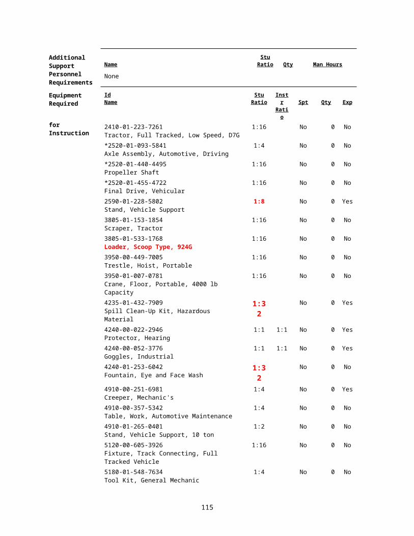
NAME: CLASS #:
UNIT:
ATTEMPT #:
Station #4: Replace a Rear Drive Shaft (This task will be 2:1 for safety reasons).
Performance Measures GO NO GO
1. All safety procedures followed:
a. Removed watches, ID tags and rings.b. Hearing protection worn if vehicle was running.c. Safety boots worn.d. Eye protection worn when under vehicle.
2. Used applicable reference(s).
3. Removed 8 cap screws holding drive shaft to transmission yoke and differential yoke.
4. Pushed the halves together and Removed rear drive shaft from the vehicle.
5. Positioned the rear drive shaft so that sliding yoke is near the front of the vehicle.
6. Positioned the universal joint on the transmission yoke, and install the four cap screws finger tight.
7. Pulled halves of drive shaft apart and position the universal joint on the differential yoke and install 4 cap screws finger tight.
8. Tightened the 8 cap screws.
Evaluator’s Overall Rating:Evaluator’s Comments:
Evaluator's Signature: ____________________________________
Date: ___________________________________
B-16

TEST ANSWER(S) FOR LESSON 5: 91L10E05 version 1
1. TLO ( 1) [1]
2. TLO ( 3) [2]
B-17
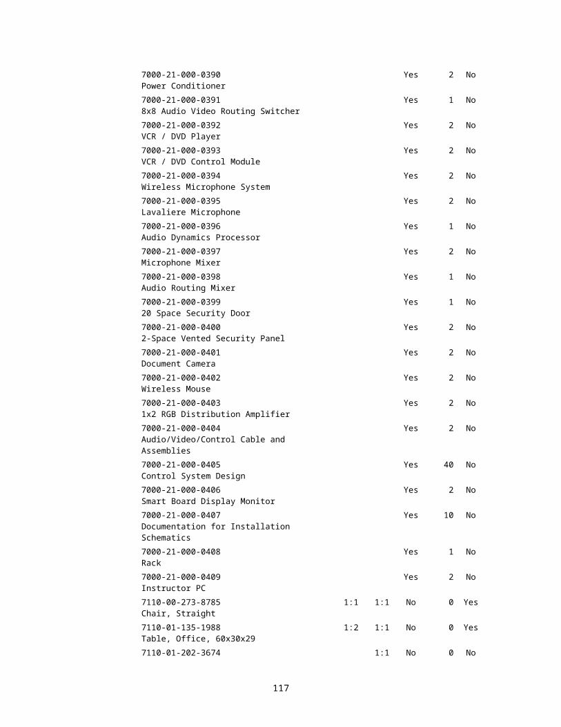
Appendix C - Practical Exercises and Solutions
PRACTICAL EXERCISE(S)/SOLUTION(S) FOR LESSON 2: 91L10E02 version 1
PRACTICAL EXERCISE SHEET 91L10E02PE1
Title Implement Transmission Troubleshooting, Repair, and Adjustments.
Lesson Number / Title
91L10E02 version 1 / Torque Converters, Transmissions, Planetary Gears and Clutches
Introduction Introduce the instructors for this practical exercise and inform the students of the subject being covered.
Motivator In order to be a competent construction equipment repairer, you must understand and be able to perform power shift transmission troubleshooting, repair and adjustments. During this practical exercise, you will be introduced to some the techniques used to do this.
Learning Step/Activity
NOTE: The instructor should inform the students of the following Learning Step/Activity requirements. (TLO Step 5)
At the completion of this lesson, you [the student] will:Action: Implement transmission troubleshooting, repair, and adjustments.
Safety Requirements
There is a possibility of injury while lifting heavy objects during this lesson. Use proper lifting techniques and use lifting devices. Remove all jewelry to include ID tags and wedding bands when working on equipment. Use caution around moving parts. You will wear eye and foot protection when required by the instructor, while working around equipment. You will be provided and required to wear aural protectors while equipment is in operation. Follow all safety procedures. The use of Personal protective Equipment (PPE) by students and instructors is mandatory. Further guidance concerning PPE can be found in OSHA regulations 29 CFR 1910.132; 29 CFR 1910.133; 29 CFR 1910.136; 29 CFR 1910.138; and 29 CFR 1910.95.
Risk Assessment
Medium - The risk assessment for this module has been reviewed and signed by the responsible officer. Review the deliberate risk assessment, perform a daily risk assessment, and ensure it is recorded on appropriate forms, signed by authorized command authority, and posted at the training site.
Environmental Considerations
There is a possibility of environmental contamination by Petroleum, Oil, and Lubricants (POL), fuel, and cleaning solvents. You will be briefed on the proper disposal of POL products and how to properly clean up spills prior to each practical exercise. Ensure spill kits are available and there location identified. Instructors should complete a risk assessment before conducting training, operations, or logistical activities. Risk assessments assist instructors in identifying potential environmental hazards, develop controls, make risk decisions, implement controls, and ensure proper supervision and evaluation.
Evaluation Practical Exercise
Instructional Lead-In
NOTE: Briefly review the general safety requirements, risk assessments, and environmental considerations associated with this lesson.
C-1

Explain to students:
a. Safety is a top priority and will be monitored and enforced throughout this practical exercise.
b. This practical exercise is 9 hours long and will consist of four stations with multiple requirements.
c. The stations will be conducted in a round robin style.
d. You will be working in groups of four, one group per item of equipment.
e. An instructor will start and operate the equipment as required.
f. You must read all safety warnings.
g. A safety briefing will be given at each station pertinent to that station.
h. If you have any questions or problems during this practical exercise contact an instructor prior to continuing.
Resource Requirements
Instructor Materials:
TM 5-2410-237-23TM 5-2420-224-20-1TM 5-3805-248-23-1 & 23-2TM 5-3805-262-20TM 5-3805-262-24PTM 5-3805-262-34TM 9-8000FOS 40FOS 54POLCaterpillar Dealer Training Course Guide 27Caterpillar Training Guide 33, Basic Power Shift - Planetary GearingCaterpillar Training Guide 44, Basic Power Shift - Torque Converters29 CFR 1910.1200 Hazard Communication 01 Jul 200329 CFR 1910.132 Personnel Protective 01 Jul 2003
Equipment –General Requirements
29 CFR 1910.133 Eye and Face Protection 01 Jul 200329 CFR 1910.136 Foot Protection 01 Jul 200329 CFR 1910.138 Hand Protection 01 Jul 200329 CFR 1910.95 Occupational Noise 01 Jul 2003
ExposureHearing Protection
Eye Protection
Student Materials: TM 5-2410-237-23TM 5-2420-224-20-1TM 5-3805-248-23-1 & 23-2TM 5-3805-262-20TM 5-3805-262-24P
C-2

TM 5-3805-262-34Student GuidesPens and PencilsHearing ProtectionEye ProtectionSafety BootsCoveralls
Work Gloves
Special Instructions
Instructor will:
a. Perform a safety briefing at each station pertinent to that station.
b. Start and operate equipment for students as required.
c. Ensure safety is monitored and enforced throughout this practical exercise.
d. Ensure each station has the applicable Technical Manuals (TMs) and forms as required.
e. Ensure all PPE is available at the appropriate stations.
f. Ensure all required tools are at each station.
g. Ensure that each station has a copy of the practical exercise applicable for that station.
h. Assist students as required.
Instructors will inform the students that:
At Station One (621B Scrapers), students will locate in the TM and inform the instructor on the procedures for performing a Transmission Shift Point Adjustment IAW TM 5-3805-248-23-1 & 23-2. No jewelry, ID tags, or rings will be worn during this PE. Eye protection must be worn while running tests. Hearing protection must be worn while the engine is running.
At Station Two (MW24C Loaders), students will perform a Transmission Pressure Check for Slow or Erratic Transmission Shifting IAW TM 5-3805-262-34 and TM 9-4910-571-12&P. No jewelry, ID tags, or rings will be worn during this PE. Eye protection must be worn while running tests. Hearing protection must be worn while the engine is running.
At Station Three (Power Shift Transmission D7G), students will be given the problem of Incorrect Response to Transmission Selector Movement IAW TM 5-2410-237-23. No jewelry, ID tags, or rings will be worn during this PE. Eye protection must be worn while running tests. Hearing protection must be worn while the engine is running.
Students will be walked through the winch brake adjustment.
At Station Four, students will use TM 5-2410-237-23, WP 0245 15, page 0245 15-1 and disassemble, inspect, identify the components, and reassemble the D7 transmission. This will help them identify the transmission components, how they work together, how the components wear and the problems they can cause.
C-3

ProceduresStation #1:
At this station, you have a 621B Scraper that is not shifting properly. Locate in TM 5-3805-248-23-1, the fault “WHEN CHANGING GEARS, THE TRANSMISSION STAYS IN A PREVIOUS GEAR” and inform the instructor of the first probable cause.
Students read and understand all warnings and cautions.
When told to do so, perform the test with TMDE provided.
Check the governor oil pressure IAW TM 5-3805-248-23-1 AND 23-2 and test #50 IAW TM 9-4910-571-12&P.
Inform the instructor of the results.
Shut down and disconnect TMDE when told to do so.
C-4

Station #2:
At this station, you have a MW24C Scoop Loader that has slow or erratic transmission shifting. Using TM 5-3805-262-20, locate "Troubleshooting". Under "Transmission", locate "Slow or erratic transmission shifting".
Students read and understand all warnings and cautions. When told to do so, perform steps #1 through #3 IAW the TM Troubleshooting Guide.
Inform the instructor of the requirements for step #4 IAW the TM Troubleshooting Guide.
Answer the instructor’s questions and wait for further guidance.
Using TM 5-3805-262-34, locate "Troubleshooting". Under "Transmission", locate "Slow or erratic transmission shifting".
Inform the instructor of the steps to follow IAW the TM Troubleshooting Guide.
When told to do so, perform the test with TMDE provided.
Check the transmission oil pressure IAW TM 5-3805-262-34 and test #50 IAW TM 9-4910-571-12&P.
Annotate all readings using the example below:
Position Book Results Actual Results
N 135 psi.
R 135 psi.
F 135 psi.
H 125-132 psi.
Inform instructor of the results.
Shut down and disconnect TMDE when told to do so.
C-5

Station #3:
At this station, you have D7G Bulldozer that HAS, INCORRECT RESPONSE TO TRANSMISSION SELECTOR MOVEMENT. Using TM 5-2410-237-23, locate "Troubleshooting". Under "Symptom Index", locate UNDER TRANSMISSION TROUBLESHOOTING “INCORRECT RESPONSE TO TRANSMISSIONSELECTOR MOVEMENT".
Students read and understand all warnings and cautions.
Inform the instructor of the steps to follow IAW the TM Troubleshooting Guide.CHECK TRANSMISSION OIL LEVEL IN ACCORDANCE WITH WP 0107 00
When told to do so, check the transmission shift lever adjustment and adjust, if needed.
D7G Dozer Winch Brake: the student should refer to TM 5-2410-237-23 and with the instructor's guidance, perform a winch brake adjustment.
C-6

Station #4:
At this station, you have a D7 transmission that you will disassemble, inspect the components, explain the operation of the components to the instructor and reassemble the transmission.
Students read and understand all warnings and cautions.
Feedback Requirements
C-7

SOLUTION FORPRACTICAL EXERCISE SHEET 91L10E02PE1
Station #1:
Student should have located in TM 5-3805-248-23-1, TABLE OF CONTENTS PAGE i, TROUBLESHOOTING SYMPTOM INDEX ON PAGE 008 00-2, UNDER TRANSMISSION, FAULT NUMBER 8, “WHEN CHANGING GEARS, THE TRANSMISSION STAYS IN A PREVIOUS GEAR” ON PAGE 0013 00-3.
STEP 1 IS CHECK SHIFT POINTS ADJUSTMENT (WP 0285 00) IN TM 5-3805-248-23-2. THE ACTUAL ADJUSTMENT STARTS ON PAGE 0285 00-4.
Performed pressure test with TMDE provided.
Checked the governor oil pressure IAW TM 5-3805-248-23-2 and test #50 IAW TM 9-4910-571-12&P.
Informed the instructor of the results.
Station #2:
The student should have referred to page 2-85 in TM 5-3805-262-34. Inform the student that the transmission oil level has been checked and is OK. The transducer and adapter may already be installed or you may have the students install the adapter. The student should have properly hooked up the TMDE using the correct transducer, and performed an OFF-SET Test. Operate the equipment for the student. The student should have instructed you what to do IAW the TM. The student should have conducted a pressure test IAW TM 9-4910-571-12&P. You may stop the test after the first reading or complete all ranges. If the pressure is not 135 psi, ask the students what the causes may be, i.e. cold oil, not up to operating temperature, etc.
Station #3:
The student should have used TM 5-2410-237-23 to locate "INCORRECT RESPONSE TO TRANSMISSION SELECTOR LEVER MOVEMENT", Malfunction 2, under Transmission in the “Troubleshooting Symptom Index", located ON PAGE 0005 00-3.This will send them to page 0006 00-17.
Informed the instructor as to which steps were followed, IAW the TM Troubleshooting Guide.
STUDENTS SHOULD HAVE CHECKED THE TRANSMISSION OIL LEVEL IN ACCORDANCE WITH (WP 0107 00).
THE INSTRUCTOR WILL HAVE STUDENTS PERFORM TRANSMISSION SHIFT LINKAGE ADJUSTMENT IAW TM 5-2410-237-23, (WP 0104 00).
The student should have referred to TM 5-2410-237-23 and with the instructor's guidance, performed a winch brake, adjustment.
Informed instructor of the results.
Station #4:
D7G Transmission: The student should have disassembled, identified and inspected the components, explained the operation of the components and reassembled the transmission.
C-8

PRACTICAL EXERCISE(S)/SOLUTION(S) FOR LESSON 3: 91L10E03 version 1
PRACTICAL EXERCISE SHEET 91L10E03PE1
Title Implement differential and axle troubleshooting, repair, replacement, and adjustment.
Lesson Number / Title
91L10E03 version 1 / Differentials and Axles
Introduction Introduce the instructors for this practical exercise and inform the students of the subject being covered.
Motivator In order to be a competent construction equipment repairer, you must understand and be able to perform differential and axle troubleshooting, repair and adjustments. During this practical exercise, you will be introduced to some of the techniques used to do this.
Learning Step/Activity
NOTE: The instructor should inform the students of the following Learning Step/Activity requirements. (TLO Step 3)
At the completion of this lesson, you [the student] will:Action: Implement differential and axle troubleshooting, repair, replacement,
and adjustment.
Safety Requirements
There is a possibility of injury while lifting heavy objects during this lesson. Use proper lifting techniques and use lifting devices. Remove all jewelry to include ID tags and wedding bands when working on equipment. Use caution around moving parts. You will wear eye and foot protection when required by the instructor, while working around equipment. You will be provided and required to wear aural protectors while equipment is in operation. Follow all safety procedures. The use of Personal protective Equipment (PPE) by students and instructors is mandatory. Further guidance concerning PPE can be found in OSHA regulations 29 CFR 1910.132; 29 CFR 1910.133; 29 CFR 1910.136; 29 CFR 1910.138; and 29 CFR 1910.95.
Risk Assessment
Medium - The risk assessment for this module has been reviewed and signed by the responsible officer. Review the deliberate risk assessment, perform a daily risk assessment, and ensure it is recorded on appropriate forms, signed by authorized command authority, and posted at the training site.
Environmental Considerations
There is a possibility of environmental contamination by Petroleum, Oil, and Lubricants (POL), fuel, and cleaning solvents. You will be briefed on the proper disposal of POL products and how to properly clean up spills prior to each practical exercise. Ensure spill kits are available and there location identified. Instructors should complete a risk assessment before conducting training, operations, or logistical activities. Risk assessments assist instructors in identifying potential environmental hazards, develop controls, make risk decisions, implement controls, and ensure proper supervision and evaluation.
Evaluation Practical Exercise
Instructional Lead-In
NOTE: Briefly review the general safety requirements, risk assessments, and environmental considerations associated with this lesson.
C-9

Explain to students:
a. Safety is a top priority and will be monitored and enforced throughout this practical exercise.
b. This practical exercise is 5 hours 30 minutes long and will consist of 3 stations with multiple requirements.
c. The stations will be conducted in a round robin style.
d. You will be working in groups of four, one group per item of equipment.
e. An instructor will start and operate the equipment as required.
f. You must read all safety warnings.
g. A safety briefing will be given at each station pertinent to that station.
h. If you have any questions or problems during this practical exercise contact an instructor prior to continuing.
Resource Requirements
Instructor Materials:
TM 5-2350-262-20-1TM 5-2350-262-20-2TM 5-3805-262-20TM 5-3805-262-24PTM 5-3805-262-34TM 9-214TM 9-8000FOS 40FOS 5429 CFR 1910.1200 Hazard Communication 01 Jul 200329 CFR 1910.132 Personnel Protective 01 Jul 2003
Equipment –General Requirements
29 CFR 1910.133 Eye and Face Protection 01 Jul 200329 CFR 1910.136 Foot Protection 01 Jul 200329 CFR 1910.138 Hand Protection 01 Jul 200329 CFR 1910.95 Occupational Noise 01 Jul 2003
ExposureEye Protection
Hearing Protection
Student Materials: TM 5-2350-262-20-1TM 5-2350-262-20-2TM 5-3805-262-20TM 5-3805-262-24PTM 5-3805-262-34TM 9-214TM 9-8000LO 5-3805-262-12Student Guides
C-10

Pens and PencilsHearing ProtectionEye ProtectionSafety BootsCoveralls
Work Gloves
Special Instructions
Instructor will:
a. Instructors will walk students through each station of the round robin and:
1) Point out the location of all necessary tools and equipment.
2) Demonstrate the requirements for each station.
3) Demonstrate the correct use of tools/TMDE for each station.
b. Perform a safety briefing at each station pertinent to that station.
c. Start and operate equipment for students as required.
d. Ensure safety is monitored and enforced throughout this practical exercise.
e. Ensure each station has the applicable Technical Manuals (TMs) and forms as required.
f. Ensure all PPE is available at the appropriate stations.
g. Ensure all required tools are at each station.
h. Ensure that each station has a copy of the practical exercise applicable for that station.
i. Assist students as required.
Instructors will inform the students that:
At station one (MW24C loader), you will correct excessive drive shaft vibration of the front drive shaft and lubricant leaking from front differential carrier. No jewelry, ID tags, or rings will be worn during this PE. Eye protection, safety boots and coveralls must be worn while performing this PE.
At station two, you will replace a differential and axle assembly. No jewelry, ID tags, or rings will be worn during this PE. Safety boots must be worn while performing this PE.
At station three (M9 ACE), you will correct excessive noise or vibration and excessive engine vibration. No jewelry, ID tags, or rings will be worn during this PE. Safety boots must be worn while performing this PE.
ProceduresStation #1:
At this station, you have an MW24C Loader with excessive drive shaft (propeller) vibration of the rear drive shaft. Using TM 5-3805-262-20, determine and correct the fault.
C-11

Students read and understand all warnings and cautions.
Locate "Troubleshooting", and then locate "Excessive Drive Shaft Vibration". When told to do so, perform steps #1 through #5 IAW the TM Troubleshooting Guide.
Answer the instructor’s questions and wait for further guidance.
Inform the instructor of the results.
C-12
Station #2:
At this station, you have an axle assembly. Following the instructor’s guidance, you are to remove an axle shaft, final drive and differential, inspect them per the instructor’s guidance and replace them.
Students read and understand all warnings and cautions.
C-13

Station #3:
At this station, you have an M9 ACE with excessive noise or vibration and excessive engine vibration. Using TM 5-2350-262-20-1 and TM 5-2350-262-20-2 determine and correct the faults.
Locate "Troubleshooting" in TM 5-2350-262-20-1 and then locate "Excessive Noise or Vibration" or "Engine Vibrates Excessively".
Students read and understand all warnings and cautions.
When told to do so, perform steps #1 and #2 IAW the TM Troubleshooting Guide.
Inform instructor what further steps the TM Troubleshooting Guide leads you to.
Answer the instructor’s questions and wait for further guidance.
Feedback Requirements
C-14

SOLUTION FORPRACTICAL EXERCISE SHEET 91L10E03PE1
Station #1:
The student should have located "Troubleshooting" on pg. 3-3, and then located "Excessive Drive Shaft Vibration" on pg. 3-109. When told to do so, performed steps #1 through #5 IAW the TM Troubleshooting Guide.
Answered the instructor’s questions and waited for further guidance.
Informed the instructor of the results.
Have Students Remove Rear Drive Shaft.
Station #2:
Using the applicable manual, the instructor will guide the students through the disassembly of the axle assembly, removing the axle shaft, final drive and differential and replacing the differential, axle and final drive assembly.
Station #3:
The student should have located "Troubleshooting" in TM 5-2350-262-20-1 and then located "Excessive Noise or Vibration" or "Engine Vibrates Excessively".
When told to do so, performed steps #1 and #2 IAW the TM Troubleshooting Guide.
Informed instructor what further steps the TM Troubleshooting Guide led them to.
Answered the instructor’s questions and waited for further guidance.
Removed and installed the driveshaft IAW TM 5-2350-262-20-2.
C-15
PRACTICAL EXERCISE(S)/SOLUTION(S) FOR LESSON 4: 91L10E04 version 1
PRACTICAL EXERCISE SHEET 91L10E04PE1
Title Implement final drive component repair, replacement and adjustments.
Lesson Number / Title
91L10E04 version 1 / Final Drives
Introduction Introduce the instructors for this practical exercise and inform the students of the subject being covered.
Motivator In order to be a competent construction equipment repairer, you must understand and be able to perform final drive troubleshooting, repair and adjustments. During this practical exercise, you will be introduced to some the techniques used to do this.
Learning Step/Activity
NOTE: The instructor should inform the students of the following Learning Step/Activity requirements. (TLO Step 5)
At the completion of this lesson, you [the student] will:Action: Implement final drive component repair, replacement and
adjustments.
Safety Requirements
There is a possibility of injury while lifting heavy objects during this lesson. Use proper lifting techniques and use lifting devices. Remove all jewelry to include ID tags and wedding bands when working on equipment. Use caution around moving parts. You will wear eye and foot protection when required by the instructor while working around equipment. You will be provided and required to wear aural protectors while equipment is in operation. Follow all safety procedures. The use of Personal protective Equipment (PPE) by students and instructors is mandatory. Further guidance concerning PPE can be found in OSHA regulations 29 CFR 1910.132; 29 CFR 1910.133; 29 CFR 1910.136; 29 CFR 1910.138; and 29 CFR 1910.95.
Risk Assessment
Medium - The risk assessment for this module has been reviewed and signed by the responsible officer. Review the deliberate risk assessment, perform a daily risk assessment, and ensure it is recorded on appropriate forms, signed by authorized command authority, and posted at the training site.
Environmental Considerations
There is a possibility of environmental contamination by Petroleum, Oil and Lubricants (POL), fuel, and cleaning solvents. You will be briefed on the proper disposal of POL products and how to properly clean up spills prior to each practical exercise. Ensure spill kits are available and there location identified. Instructors should complete a risk assessment before conducting training, operations, or logistical activities. Risk assessments assist instructors in identifying potential environmental hazards, develop controls, make risk decisions, implement controls, and ensure proper supervision and evaluation.
Evaluation Practical Exercise
Instructional Lead-In
NOTE: Briefly review the general safety requirements, risk assessments, and environmental considerations associated with this lesson.
Explain to students:
C-16

a. Safety is a top priority and will be monitored and enforced throughout this practical exercise.
b. This practical exercise consists of four stations with multiple requirements.
c. The stations will be conducted in a round robin style.
d. You will be working in groups of four, one group per item of equipment.
e. An instructor will start and operate the equipment as required.
f. You must read all safety warnings.
g. A safety briefing will be given at each station pertinent to that station.
h. If you have any questions or problems during this practical exercise contact an instructor prior to continuing.
Resource Requirements
Instructor Materials:
TM 5-2350-262-20-1TM 5-2350-262-20-2TM 5-2410-237-20TM 5-2410-237-34TM 5-3805-248-23-1TM 5-3805-248-23-2TM 9-214TM 9-8000FOS 40FOS 54POL29 CFR 1910.1200 Hazard Communication 01 Jul 200329 CFR 1910.132 Personnel Protective 01 Jul 2003
Equipment –General Requirements
29 CFR 1910.133 Eye and Face Protection 01 Jul 200329 CFR 1910.136 Foot Protection 01 Jul 200329 CFR 1910.138 Hand Protection 01 Jul 200329 CFR 1910.95 Occupational Noise 01 Jul 2003
ExposureHearing Protection
Eye Protection
Student Materials: TM 5-2350-262-20-1TM 5-2350-262-20-2TM 5-2410-237-23TM 5-3805-248-23-1TM 5-3805-248-23-2TM 9-214TM 9-8000Student GuidesPens and Pencils
C-17

Hearing ProtectionEye ProtectionSafety Boots
Coveralls
Special Instructions
Inform the students the allotted time for this PE is 8 hours.
Perform a safety briefing at each station pertinent to that station.
Start and operate equipment for students as required.
Ensure safety is monitored and enforced throughout this Practical Exercise.
Ensure each station has the applicable Technical Manuals (TMs) as required.
Ensure all PPE is available at the appropriate stations.
Ensure all required equipment and tools are at each station.
Ensure that each station has a copy of the Practical Exercise sheet pertinent to the station.
Assist students as required.
Explain to the students that:
At Station One (621B Scraper), students will remove, disassemble, inspect, reassemble, and replace the 621B final drive assembly IAW TM 5-3805-248-23-1& 23-2. No jewelry, ID tags, or rings will be worn during this PE. Eye protection, safety boots and coveralls must be worn while performing this PE. Work gloves will be worn while removing and reassembling heavy components.
At Station Two (D7G Dozer), students will perform a steering clutch, steering brake, track and winch brake repair IAW TM 5-3805-237-23. No jewelry, ID tags, or rings will be worn during this PE.
At Station Three (M9 ACE Mock-Ups), students will disconnect and connect a final drive assembly IAW TM 5-2350-262-20-1 and TM 5-2350-262-20-2. No jewelry, ID tags, or rings will be worn during this PE.
At Station Four (D7G Dozer), students will repair a track, adjust a track, and replace a track shoe. No jewelry, ID tags, or rings will be worn during this PE. Eye protection, safety boots and coveralls must be worn while performing this PE. Work gloves will be worn while removing and reassembling heavy components.
ProceduresStation #1:
At this station, you have a 621B Scraper. Using TM 5-3805-248-23-1& 23-2 and following the instructor’s guidance, you will remove, disassemble, inspect, reassemble and replace the final drive assembly.
Students read and understand all warnings and cautions.
C-18

Station #2:
At this station, you have a D7G Dozer. Using TM 5-3805-237-23 and following the instructor's guidance, you will perform a steering brake and steering clutch linkage adjustment.
Students read and understand all warnings and cautions.
C-19
Station #3:
At this station, you have a final drive M9 ACE Mock-Up. Following the instructor’s guidance and TM 5-2350-262-20-1 and 20-2, you will disconnect and reconnect the final drive assembly.
Students read and understand all warnings and cautions.
C-20
Station #4:
At this station, you have a D7G Dozer with an unserviceable track or track component. You are to replace the unserviceable track or component, and adjust the track (IAW) TM 5-2410-237-23. Follow all warnings and instructor’s guidance.
Students read and understand all warnings and cautions.
Feedback Requirements
C-21

SOLUTION FORPRACTICAL EXERCISE SHEET 91L10E04PE1
Station #1:
There are no correct solutions for this Practical Exercise. The sole purpose of this period of instruction is to provide students with the experience of successfully removing, disassembling, inspecting, and reassembling a final drive assembly on a 621B Scraper IAW TM 5-3805-248-23-1 & 23-2.
Station #2:
The student should have referred to TM 5-3805-237-23 and followed the instructor's guidance, performed a steering brake and steering clutch linkage adjustment. The instructor will explain how to adjust the track on a D7G Dozer.
Station #3:
There are no correct solutions for this Practical Exercise. The sole purpose of this period of instruction is to provide students with the experience of successfully disconnecting and reconnecting a final drive assembly on an M9 ACE Mock-Up IAW TM 5-2350-262-20-2.
Station #4:
The student should have referred to TM 5-2410-237-23, page 0132 00-1, inspect the tracks and undercarriage, then to page 0143 00-1 track replacement. Following the instructor’s guidance and the instructions in the TM, the student should break and connect one track and be talked through on how to adjust the track.
C-22

Appendix D - Student Handouts (N/A)
D-1