ccna final project file to b printed
DESCRIPTION
CCNA project reportTRANSCRIPT

NETWORK ESSENTIALS
Computer network is an interconnection of two or more computers and peripherals such as printer and faxes.
Computer network allows the user to share and transfer information using cables or modem with a network.
NEED FOR COMPUTER NETWORK
Computer network allows the user to share data with other users in a network for example printers and faxes. Printer can be installed on one computer and can be accessed by other users in a network by this the need of installing the printer is avoided on individual computers. This results in cost effectiveness.
Computer network also allows the user to communicate with each other using instant messaging tools to share ideas, files or solve queries.
TYPES OF NETWORKS
1

LOCAL AEA NETWORK (LAN)
A local area network (LAN) is a computer network covering a small physical area, like a home, office, or small groups of buildings, such as a school, or an airport. The defining characteristics of LANs, in contrast to wide area networks (WANs), include their usually higher data-transfer rates, smaller geographic area, and lack of a need for leased telecommunication lines.
Switched Ethernet is the most common Data Link Layer implementation on local area
networks. At the Network Layer, the Internet Protocol (i.e. TCP/IP) has become the standard.
Smaller LANs generally consist of one or more switches linked to each other—often at least
one is connected to a router, cable modem, or ADSL modem for Internet access.
Larger LANs are characterized by their use of redundant links with switches using
the spanning tree protocol to prevent loops, their ability to manage differing traffic types
via quality of service (QoS), and to segregate traffic with VLANs. Larger LANs also contain
a wide variety of network devices such as switches, firewalls, routers, load balancers, and
sensors.[9]
LANs may have connections with other LANs via leased lines, leased services, or by
tunneling across the Internet using virtual private network technologies. Depending on how
the connections are established and secured in a LAN, and the distance involved, a LAN may
also be classified as METROPOLITAN AREA NETWORK (MAN)
CAMPUS AREA NETWORK (CAN)
A campus network is a computer network made up of an interconnection of local area
networks (LANs) within a limited geographical area.[1][2] The networking equipments
(switches, routers) and transmission media (optical fiber, copper plant, Cat5 cabling etc) are
almost entirely owned (by the campus tenant / owner: an enterprise, university, government
etc).
In the case of a university campus-based campus network, the network is likely to link a
variety of campus buildings including; academic departments, the university library and
student residence halls.
METROPOLITAN AREA NETWORK (MAN)
A metropolitan area network (MAN) is a large computer network that usually spans a city
or a large campus. A MAN usually interconnects a number of local area networks (LANs)
2

using a high-capacity backbone technology, such as fiber-optical links, and provides up-link
services to wide area networks (or WAN) and the Internet.
The IEEE 802-2001 standard describes a MAN as being
A MAN is optimized for a larger geographical area than a LAN, ranging from several blocks of buildings to entire cities. MANs can also depend on communications channels of moderate-to-high data rates. A MAN might be owned and operated by a single organization, but it usually will be used by many individuals and organizations. MANs might also be owned and operated as public utilities. They will often provide means for internetworking of local networks.
WIDE AREA NETWORK (WAN)
A wide area network (WAN) is a computer network that covers a broad area (i.e., any network whose communications links cross metropolitan, regional, or national boundaries). This is in contrast with personal area networks (PANs), local area networks (LANs), campus area networks (CANs), or metropolitan area networks (MANs) which are usually limited to a room, building, campus or specific metropolitan area (e.g., a city) respectively.
WANs are used to connect LANs and other types of networks together, so that users and computers in one location can communicate with users and computers in other locations. Many WANs are built for one particular organization and are private. Others, built by Internet service providers, provide connections from an organization's LAN to the Internet. WANs are often built using leased lines. At each end of the leased line, a router connects to the LAN on one side and a hub within the WAN on the other. Leased lines can be very expensive. Instead of using leased lines, WANs can also be built using less costly circuit switching or packet switching methods.
Network protocols including TCP/IP deliver transport and addressing functions. Protocols including Packet over SONET/SDH, MPLS, ATM and Frame relay are often used by service providers to deliver the links that are used in WANs. X.25was an important early WAN protocol, and is often considered to be the "grandfather" of Frame Relay as many of the underlying protocols and functions of X.25 are still in use today (with upgrades) by Frame Relay.
There are also several ways to connect NonStop S-series servers to WANs, including via the
ServerNet Wide Area Network (SWAN) or SWAN 2 concentrator, which provides WAN
client connectivity to servers that have Ethernet ports and appropriate communications
software. You can also use the Asynchronous Wide Area Network (AWAN) access server,
which offers economical asynchronous-only WAN access. Several options are available for
WAN connectivity:
Options: Description Advantage Disadvantage Bandwidth Sample Protocols
3

s s Range Used
Leased Point-to-Point
connection between
two computers or
LANs.
Most
Secure
Expensive
PPP, HDLC, SDLC, HNAS
Circuit
Switchin
g
A dedicated circuit
path is created
between end points.
Best example is dial-
up connections
Less Expensive
Call Setup28 - 144 kbps
PPP,ISDN
Packet
Switchin
g
Devices transport
packets via a shared
single
point-to-point/point-
to-multipoint link
across a carrier
internetwork. Variable
length packets are
transmitted over PVC
or SVC
(Permanent/Switched
Virtual Circuits (SVC)
Shared media across link
X.25 Frame-Relay
Cell
Relay
Similar to packet
switching, but uses
fixed length cells.
Data is divided in
fixed-length cells and
transported across
virtual circuits
Best for
simultaneo
us use of
voice and
data
Overhead can
be
considerable
ATM
Transmission rates usually range from 1200 bps to 24 Mbps, although some connections such
as ATM and Leased lines can reach speeds greater than 156 Mbps. Typical communication
links used in WANs are telephone lines, microwave links & satellite channels.
Recently with the proliferation of low cost of Internet connectivity many companies and
organizations have turned to VPN to interconnect their networks, creating a WAN in that
4

way. Companies such as Cisco, New Edge Networks and Check Point offer solutions to
create VPN networks.
TOPOLOGIES
Topology is a pattern of computer devices and describes the way in which these devices are connected. Topology can be physical or logical. Physical topology refers to the physical structure of network, while a logical topology determines the way in which the data actually passes through the network from one device to the other.
TYPES OF TOPOLOGIES
(1) Star topology(2) Bus topology(3) Ring topology(4) Mesh topology(5) Tree topology(6) Hybrid topology
STAR TOPOLOGY
Star networks are one of the most common computer network topologies. In its simplest
form, a star network consists of one central switch, hub or computer, which acts as a conduit
to transmit messages. Thus, the hub and leaf nodes, and the transmission lines between them,
form a graph with the topology of a star. If the central node is passive, the originating node
must be able to tolerate the reception of an echo of its own transmission, delayed by the two-
way transmission time (i.e. to and from the central node) plus any delay generated in the
central node. An active star network has an active central node that usually has the means to
prevent echo-related problems.
5

The star topology reduces the chance of network failure by connecting all of the systems to a
central node. When applied to a bus-based network, this central hub rebroadcasts all
transmissions received from any peripheral node to all peripheral nodes on the network,
sometimes including the originating node. All peripheral nodes may thus communicate with
all others by transmitting to, and receiving from, the central node only. The failure of a
transmission line linking any peripheral node to the central node will result in the isolation of
that peripheral node from all others, but the rest of the systems will be unaffected.
It is also designed with each node (file servers, workstations, and peripherals) connected
directly to a central network hub, switch, or concentrator.
Data on a star network passes through the hub, switch, or concentrator before continuing to
its destination. The hub, switch, or concentrator manages and controls all functions of the
network. It is also acts as a repeater for the data flow. This configuration is common
with twisted pair cable. However, it can also be used with coaxial cable or optical fibre cable.
Advantages
Better performance: Star topology prevents the passing of data packets through an
excessive number of nodes. At most, 3 devices and 2 links are involved in any
communication between any two devices. Although this topology places a huge overhead
on the central hub, with adequate capacity, the hub can handle very high utilization by
one device without affecting others.
Isolation of devices: Each device is inherently isolated by the link that connects it to the
hub. This makes the isolation of individual devices straightforward and amounts to
disconnecting each device from the others. This isolation also prevents any non-
centralized failure from affecting the network.
Benefits from centralization: As the central hub is the bottleneck, increasing its
capacity, or connecting additional devices to it, increases the size of the network very
easily. Centralization also allows the inspection of traffic through the network. This
facilitates analysis of the traffic and detection of suspicious behavior.
Simplicity: This topology is easy to understand, establish, and navigate. Its simplicity
obviates the need for complex routing or message passing protocols. Also, as noted
earlier, the isolation and centralization it allows simplify fault detection, as each link or
device can be probed individually.
Easy to install and wire.
Easy to detect faults and to remove parts.
No disruptions to the network when connecting or removing devices.
6

Disadvantages
The primary disadvantage of a star topology is the high dependence of the system on the
functioning of the central hub. While the failure of an individual link only results in the
isolation of a single node, the failure of the central hub renders the network inoperable,
immediately isolating all nodes. The performance and scalability of the network also depend
on the capabilities of the hub. Network size is limited by the number of connections that can
be made to the hub, and performance for the entire network is capped by its throughput.
While in theory traffic between the hub and a node is isolated from other nodes on the
network, other nodes may see a performance drop if traffic to another node occupies a
significant portion of the central node's processing capability or throughput. Furthermore,
wiring up of the system can be very complex and high costing.
BUS TOPOLOGY
A bus network topology is a network architecture in which a set of clients are connected via
a shared communications line, called a bus. There are several common instances of the bus
architecture, including one in the motherboard of most computers, and those in some versions
of Ethernet networks.
Bus networks are the simplest way to connect multiple clients, but may have problems when
two clients want to transmit at the same time on the same bus. Thus systems which use bus
network architectures normally have some scheme of collision handling or collision
avoidance for communication on the bus, quite often using Carrier Sense Multiple Access or
the presence of a bus master which controls access to the shared bus resource.
A true bus network is passive – the computers on the bus simply listen for a signal; they are
not responsible for moving the signal along. However, many active architectures can also be
described as a "bus", as they provide the same logical functions as a passive bus; for example,
7

switched Ethernet can still be regarded as a logical network, if not a physical one. Indeed, the
hardware may be abstracted away completely in the case of a software bus.
With the dominance of switched Ethernet over passive Ethernet, passive bus networks are
uncommon in wired networks. However, almost all current wireless networks can be viewed
as examples of passive bus networks, with radio propagation serving as the shared passive
medium.
The bus topology makes the addition of new devices straightforward. The term used to
describe clients is station or workstation in this type of network. Bus network topology uses a
broadcast channel which means that all attached stations can hear every transmission and all
stations have equal priority in using the network to transmit data.
The Ethernet bus topology works like a big telephone party line — before any device can
send a packet, devices on the bus must first determine that no other device is sending a packet
on the cable. When a device sends its packet out over the bus, every other network card on
the bus sees and reads the packet. Ethernet’s scheme of having devices communicate like
they were in chat room is called Carrier Sense Multiple Access/ Collision Detection
(CSMA/CD). Sometimes two cards talk (send packets) at the same time. This creates a
collision, and the cards themselves arbitrate to decide which one will resend its packet first.
All PCs on a bus network share a common wire, which also means they share the data
transfer capacity of that wire – or, in tech terms, they share its bandwidth.
This creates an interesting effect. Ten PCs chatting on a bus each get to use a much higher
proportion of its total bandwidth than, for instance, 100 PCs on the same bus (in this case,
one – tenth compared to one – hundredth). The more PCs on a bus, the more likely you’ll
have a communication traffic jam.
Advantages
Easy to implement and extend.
Easy to install.
Well-suited for temporary or small networks not requiring high speeds (quick setup).
Cheaper than other topologies.
Cost effective; only a single cable is used.
Easy identification of cable faults.
Reduced weight due to fewer wires.
8

Disadvantages
Limited cable length and number of stations.
If there is a problem with the cable, the entire network breaks down.
Maintenance costs may be higher in the long run.
Performance degrades as additional computers are added or on heavy traffic (shared
bandwidth).
Proper termination is required (loop must be in closed path).
Significant Capacitive Load (each bus transaction must be able to stretch to most distant
link).
It works best with limited number of nodes.
Slower data transfer rate than other topologies.
Only one packet can remain on the bus during one clock pulse.
RING TOPOLOGY
A ring network is a network topology in which each node connects to exactly two other
nodes, forming a single continuous pathway for signals through each node - a ring. Data
travels from node to node, with each node along the way handling every packet.
Because a ring topology provides only one pathway between any two nodes, ring networks
may be disrupted by the failure of a single link. A node failure or cable break might isolate
every node attached to the ring. FDDI networks overcome this vulnerability by sending data
on a clockwise and a counterclockwise ring: in the event of a break data is wrapped back onto
the complementary ring before it reaches the end of the cable, maintaining a path to every
node along the resulting "C-Ring". 802.5 networks -- also known as IBM Token Ring
9

networks -- avoid the weakness of a ring topology altogether: they actually use
a star topology at the physical layer and a Multistation Access Unit (MAU) toimitate a ring at
the datalink layer.
Many ring networks add a "counter-rotating ring" to form a redundant topology. Such "dual
ring" networks include Spatial Reuse Protocol, Fiber Distributed Data Interface (FDDI),
and Resilient Packet Ring.
Advantages
Very orderly network where every device has access to the token and the opportunity to
transmit
Performs better than a star topology under heavy network load
Can create much larger network using Token Ring
Does not require network server to manage the connectivity between the computers
Disadvantages
One malfunctioning workstation or bad port in the MAU can create problems for the
entire network
Moves, adds and changes of devices can affect the network
Network adapter cards and MAU's are much more expensive than Ethernet cards and
hubs
Much slower than an Ethernet network under normal load.
Misconceptions
"Token Ring is an example of a ring topology." 802.5 (Token Ring) networks do not use
a ring topology at layer 1. As explained above, IBM Token Ring (802.5)
networks imitate a ring at layer 2 but use a physical star at layer 1.
"Rings prevent collisions." The term "ring" only refers to the layout of the cables. It is
true that there are no collisions on an IBM Token Ring, but this is because of the layer 2
Media Access Control method, not the physical topology (which again is a star, not a
ring.) Token passing, not rings, prevents collisions.
"Token passing happens on rings." Token passing is a way of managing access to the
cable, implemented at the MAC sublayer of layer 2. Ring topology is the cable layout at
layer one. It is possible to do token passing on a bus (802.4) a star (802.5) or a ring
(FDDI). Token passing is not restricted to rings.
10

11

MESH TOPOLOGY
Mesh networking is a type of networking wherein each node in the network may act as an
independent router, regardless of whether it is connected to another network or not. It allows
for continuous connections and reconfiguration around broken or blocked paths by “hopping”
from node to node until the destination is reached. A mesh network whose nodes are all
connected to each other is a fully connected network. Mesh networks differ from other
networks in that the component parts can all connect to each other via multiple hops, and they
generally are not mobile. Mesh networks can be seen as one type of ad hoc network. Mobile
ad hoc networks (MANET) and mesh networks are therefore closely related, but MANET
also have to deal with the problems introduced by the mobility of the nodes. Mesh networks
are self-healing: the network can still operate when one node breaks down or a connection
goes bad. As a result, the network may typically be very reliable, as there is often more than
one path between a source and a destination in the network. Although mostly used in wireless
scenarios, this concept is also applicable to wired networks and software interaction. The
animation at the right illustrates how wireless mesh networks can self form and self heal.
Wireless mesh networks were originally developed for military applications and are typical of
mesh architectures. Over the past decade the size, cost, and power requirements of radios has
12

declined, enabling more radios to be included within each device acting as a mesh node. The
additional radios within each node enable it to support multiple functions such as client
access, backhaul service, and scanning (required for high speed handover in mobile
applications). Additionally, the reduction in radio size, cost, and power has enabled the mesh
nodes to become more modular—one node or device now can contain multiple radio cards or
modules, allowing the nodes to be customized to handle a unique set of functions and
frequency bands.
TREE TOPOLOGY
Tree topology is also known as a hierarchical network.
The type of network topology in which a central 'root' node (the top level of the hierarchy) is
connected to one or more other nodes that are one level lower in the hierarchy (i.e., the
second level) with a point-to-point link between each of the second level nodes and the top
level central 'root' node, while each of the second level nodes that are connected to the top
level central 'root' node will also have one or more other nodes that are one level lower in the
hierarchy (i.e., the third level) connected to it, also with a point-to-point link, the top level
central 'root' node being the only node that has no other node above it in the hierarchy (The
hierarchy of the tree is symmetrical.) Each node in the network having a specific fixed
number, of nodes connected to it at the next lower level in the hierarchy, the number, being
referred to as the 'branching factor' of the hierarchical tree.This tree has individual peripheral
nodes.
1. A network that is based upon the physical hierarchical topology must have at least three
13

levels in the hierarchy of the tree, since a network with a central 'root' node and only one
hierarchical level below it would exhibit the physical topology of a star.
2. A network that is based upon the physical hierarchical topology and with a branching
factor of 1 would be classified as a physical linear topology.
3. The branching factor, f, is independent of the total number of nodes in the network and,
therefore, if the nodes in the network require ports for connection to other nodes the total
number of ports per node may be kept low even though the total number of nodes is large –
this makes the effect of the cost of adding ports to each node totally dependent upon the
branching factor and may therefore be kept as low as required without any effect upon the
total number of nodes that are possible.
4. The total number of point-to-point links in a network that is based upon the physical
hierarchical topology will be one less than the total number of nodes in the network.
5. If the nodes in a network that is based upon the physical hierarchical topology are required
to perform any processing upon the data that is transmitted between nodes in the network,
the nodes that are at higher levels in the hierarchy will be required to perform more
processing operations on behalf of other nodes than the nodes that are lower in the
hierarchy. Such a type of network topology is very useful and highly recommended.
HYBRID TOPOLOGY
Hybrid networks use a combination of any two or more topologies in such a way that the
resulting network does not exhibit one of the standard topologies (e.g., bus, star, ring, etc.).
For example, a tree network connected to a tree network is still a tree network, but two star
networks connected together exhibit a hybrid network topology. A hybrid topology is always
produced when two different basic network topologies are connected. Two common
examples for Hybrid network are: star ring network and star bus network
A Star ring network consists of two or more star topologies connected using
a multistation access unit (MAU) as a centralized hub.
A Star Bus network consists of two or more star topologies connected using a bus trunk
(the bus trunk serves as the network's backbone).
While grid networks have found popularity in high-performance computing applications,
some systems have used genetic algorithms to design custom networks that have the fewest
possible hops in between different nodes. Some of the resulting layouts are nearly
incomprehensible, although they function quite well.
14

NETWORKING
OSI (Open System Interconnection)
The Open Systems Interconnection model (OSI model) is a product of the Open Systems Interconnection effort at the International Organization for Standardization. It is a way of sub-dividing a communications system into smaller parts called layers. A layer is a collection of conceptually similar functions that provide services to the layer above it and receives services from the layer below it. On each layer an instance provides services to the instances at the layer above and requests service from the layer below.
For example, a layer that provides error-free communications, across a network provides the
path needed by applications above it, while it calls the next lower layer to send and receive
packets that make up the contents of the path. Conceptually two instances at one layer are
connected by a horizontal protocol connection on that layer.
Layer 1: Physical Layer
The Physical Layer defines the electrical and physical specifications for devices. In
particular, it defines the relationship between a device and a transmission medium, such as a
copper or optical cable. This includes the layout of pins, voltages, cable
specifications, hubs, repeaters, network adapters, host bus adapters (HBAs used in storage
area networks) and more.
15

To understand the function of the Physical Layer, contrast it with the functions of the Data
Link Layer. Think of the Physical Layer as concerned primarily with the interaction of a
single device with a medium, whereas the Data Link Layer is concerned more with the
interactions of multiple devices (i.e., at least two) with a shared medium. Standards such
as RS-232 do use physical wires to control access to the medium.
The major functions and services performed by the Physical Layer are:
Establishment and termination of a connection to a communications medium.
Participation in the process whereby the communication resources are effectively shared
among multiple users.
Modulation, or conversion between the representation of digital data in user equipment
and the corresponding signals transmitted over a communications channel. These are
signals operating over the physical cabling (such as copper and optical fiber) or over
a radio link.
Ethernet incorporates both this layer and the Data Link Layer. The same applies to other
local-area networks, such as token ring, FDDI, ITU-T G.hn and IEEE 802.11, as well as
personal area networks such as Bluetooth.
Layer 2: Data Link Layer
The Data Link Layer provides the functional and procedural means to transfer data between
network entities and to detect and possibly correct errors that may occur in the Physical
Layer. Originally, this layer was intended for point-to-point and point-to-multipoint media,
characteristic of wide area media in the telephone system. Local area network architecture,
which included broadcast-capable multiaccess media, was developed independently of the
ISO work in IEEE Project 802. IEEE work assumed sublayering and management functions
not required for WAN use. In modern practice, only error detection, not flow control using
sliding window, is present in data link protocols such as Point-to-Point Protocol (PPP), and,
on local area networks, the IEEE 802.2 LLC layer is not used for most protocols on the
Ethernet, and on other local area networks, its flow control and acknowledgment mechanisms
are rarely used. Sliding window flow control and acknowledgment is used at the Transport
Layer by protocols such as TCP, but is still used in niches where X.25 offers performance
advantages.
Layer 3: Network Layer
The Network Layer provides the functional and procedural means of transferring variable
length data sequences from a source to a destination via one or more networks, while
maintaining the quality of service requested by the Transport Layer. The Network Layer
16

performs network routing functions, and might also perform fragmentation and reassembly,
and report delivery errors. Routers operate at this layer—sending data throughout the
extended network and making the Internet possible. This is a logical addressing scheme –
values are chosen by the network engineer. The addressing scheme is not hierarchical.
A number of layer management protocols belong to the Network Layer. These include
routing protocols, multicast group management, Network Layer information and error, and
Network Layer address assignment. It is the function of the payload that makes these belong
to the Network Layer, not the protocol that carries them.
Layer 4: Transport Layer
The Transport Layer provides transparent transfer of data between end users, providing
reliable data transfer services to the upper layers. The Transport Layer controls the reliability
of a given link through flow control, segmentation/desegmentation, and error control. Some
protocols are state and connection oriented. This means that the Transport Layer can keep
track of the segments and retransmit those that fail. The Transport layer also provides the
acknowledgement of the successful data transmission and if no error free data was transferred
then sends the next data.
Although not developed under the OSI Reference Model and not strictly conforming to the
OSI definition of the Transport Layer, typical examples of Layer 4 are the Transmission
Control Protocol (TCP) and User Datagram Protocol (UDP).
Of the actual OSI protocols, there are five classes of connection-mode transport protocols
ranging from class 0 (which is also known as TP0 and provides the least features) to class 4
(TP4, designed for less reliable networks, similar to the Internet). Class 0 contains no error
recovery, and was designed for use on network layers that provide error-free connections.
Class 4 is closest to TCP, although TCP contains functions, such as the graceful close, which
OSI assigns to the Session Layer.
Perhaps an easy way to visualize the Transport Layer is to compare it with a Post Office, which deals with the dispatch and classification of mail and parcels sent. Do remember, however, that a post office manages the outer envelope of mail. Higher layers may have the equivalent of double envelopes, such as cryptographic presentation services that can be read by the addressee only. Roughly speaking, tunneling protocols operate at the Transport Layer, such as carrying non-IP protocols such as IBM's SNA or Novell's IPX over an IP network, or end-to-end encryption with IPsec. While Generic Routing Encapsulation (GRE) might seem to be a Network Layer protocol, if the encapsulation of the payload takes place only at endpoint, GRE becomes closer to a transport protocol that uses IP headers but contains complete frames or packets to deliver to an endpoint. L2TP carries PPP frames inside transport packet.
17

Layer 5: Session Layer
The Session Layer controls the dialogues (connections) between computers. It establishes,
manages and terminates the connections between the local and remote application. It provides
for full-duplex, half-duplex, or simplex operation, and establishes check pointing,
adjournment, termination, and restart procedures. The OSI model made this layer responsible
for graceful close of sessions, which is a property of the Transmission Control Protocol, and
also for session check pointing and recovery, which is not usually used in the Internet
Protocol Suite. The Session Layer is commonly implemented explicitly in application
environments that use remote procedure calls.
Layer 6: Presentation Layer
The presentation layer provides a variety of coding and conversion functions that are applied
to application layer data. These functions ensure that information sent from the application
layer of one system would be readable by the application layer of another system thus
the Presentation Layer establishes context between Application Layer entities, in which the
higher-layer entities may use different syntax and semantics if the presentation service
provides a mapping between them. If a mapping is available, presentation service data units
are encapsulated into session protocol data units, and passed down the stack.
This layer provides independence from data representation (e.g., encryption) by translating
between application and network formats. The presentation layer transforms data into the
form that the application accepts. This layer formats and encrypts data to be sent across a
network. It is sometimes called the syntax layer.
Layer 7: Application Layer
The Application Layer is the OSI layer closest to the end user, which means that both the OSI
application layer and the user interact directly with the software application. This layer
interacts with software applications that implement a communicating component. Such
application programs fall outside the scope of the OSI model. Application layer functions
typically include identifying communication partners, determining resource availability, and
synchronizing communication. When identifying communication partners, the application
layer determines the identity and availability of communication partners for an application
with data to transmit. When determining resource availability, the application layer must
decide whether sufficient network or the requested communication exists. In synchronizing
communication, all communication between applications requires cooperation that is
managed by the application layer. Some examples of application layer implementations
include Hypertext Transfer Protocol (HTTP), File Transfer Protocol (FTP), Simple Mail
Transfer Protocol (SMTP) and X.400 Mail.
18

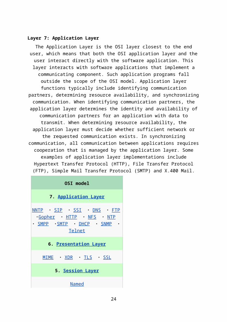
OSI model
7. Application Layer
NNTP · SIP · SSI · DNS · FTP ·Gopher · H
TTP · NFS · NTP · SMPP ·SMTP · DHCP ·
SNMP · Telnet
6. Presentation Layer
MIME · XDR · TLS · SSL
5. Session Layer
Named
Pipes · NetBIOS · SAP · SIP ·L2TP · PPTP
4. Transport Layer
TCP · UDP · SCTP · DCCP
3. Network Layer
IP · ICMP · IPsec · IGMP · IPX ·AppleTalk
2. Data Link Layer
ARP · CSLIP · SLIP · Ethernet · Frame
relay · ITU-T G.hn DLL · PPP
1. Physical Layer
RS-232 · RS-449 · V.35 · V.34 · I.430 ·I.431
· T1 · E1 · POTS · SONET/SDH ·OTN · DS
L · 802.11a/b/g/n PHY ·802.15.x PHY · ITU-
T G.hn PHY ·Ethernet · USB · Bluetooth
19

Networking Medias
Network media refers to media mainly used in computer networks such as the Internet. Network media is essentially driven by technological development, emerging from the internet as a non-centralized medium in the late nineties; the term has more recently begun to be applied to both the arts and industry. The following features distinguish Network Media from classical media, such as broadcast media and the printed press:
Comparing Media Types
The choice of media type affects the type of network interface cards installed, the speed of the network, and the ability of the network to meet future needs. Table below compares the features of the common network media, including UTP, STP, coaxial cable, fiber-optic, and wireless connections.Comparing Media Types
Media Type
Maximum Segment Length
Speed Comparative Cost
Advantages Disadvantages
UTP 100 meters 10 Mbps
100 Mbps
Least expensive Easy to in-stall, widely available, widely used
Susceptible to interference; can cover only a limited distance
STP 100 meters 10–100 Mbps
More expensive than UTP
Reduced crosstalk, less sus-ceptible to EMI than UTP or Thinnet
Difficult to work with; can cover only a limited distance
Coaxial 500 meters (Thicknet)
185 meters (Thinnet)
10–100 Mbps
Relatively inexpensive, but more costly than UTP
Less sus-ceptible to EMI than other types of copper media
Difficult to work with (Thicknet); limited bandwidth; limited application (Thinnet); damage to cable can bring down entire network
20

Media Type
Maximum Segment Length
Speed Comparative Cost
Advantages Disadvantages
Coaxial 500 meters (Thicknet)
185 meters (Thinnet)
10–100 Mbps
Relatively inexpensive, but more costly than UTP
Less susceptible to EMI than other types of copper media
Difficult to work with (Thicknet); limited bandwidth; limited application (Thinnet); damage to cable can bring down entire network
Fiber-optic
3 km and further (sin-gle-mode)
2 km and further (multimode)
10–1000 Mbps (sin-gle-mode)
100 Mbps–9.92 Gbps (multimode)
Expensive Cannot be tapped easily, so security is bet-ter; can be used over great dis-tances; not susceptible to EMI; higher data rate than coaxial and twisted-pair
Difficult to terminate
Wireless 50 km—global
1–54 Mbps Expensive Does not require in-stallation of media
Susceptible to atmospheric conditions
Twisted-Pair Cable
Twisted-pair is a copper wire-based cable that can be either shielded or unshielded. Twisted- pair is the most common media for network connectivity. Unshielded twisted-pair (UTP) cable, as shown, is a four-pair wire. Each of the eight individual copper wires in UTP cable is covered by an insulating material. In addition, the wires in each pair are twisted around each other. The advantage of UTP cable is its ability to cancel interference, because the twisted-wire pairs limit signal degradation from electromagnetic interference (EMI) and radio frequency interference (RFI). To further reduce crosstalk between the pairs in UTP cable, the
number of twists in the wire pairs varies. UTP, as well as shielded twisted-pair (STP) cable, must follow precise specifications as to how many twists or braids are permitted per meter.
Unshielded Twisted-Pair Cable
21

UTP cable is used in a variety of networks. When used as a networking medium, UTP cable has four pairs of either 22- or 24-gauge copper wire. UTP used as a networking medium has an impedance of 100 ohms, differentiating it from other types of twisted-pair wiring such as that used for telephone wiring. Because UTP cable has an external diameter of approximately 0.43 cm (0.17 inches), its small size can be advantageous during installation. Also, because UTP can be used with most of the major networking architectures, it continues to grow in popularity.
Several categories of UTP cable exist:
Category 1—Used for telephone communications; not suitable for transmitting data
Category 2—Capable of transmitting data at speeds of up to 4 Mbps
Category 3—Used in 10BASE-T networks; can transmit data at speeds up to 10 Mbps
Category 4—Used in Token Ring networks; can transmit data at speeds up to 16 Mbps
Category 5—Capable of transmitting data at speeds up to 100 Mbps
Category 5e—Used in networks running at speeds up to 1000 Mbps (1 Gbps)
Category 6—Consists of four pairs of 24-gauge copper wires that can transmit data at speeds up to 1000 Mbps
Shielded Twisted-Pair Cable
Shielded twisted-pair (STP) cable, as shown in Figure 4-2, combines the techniques of shielding and the twisting of wires to further protect against signal degradation. Each pair of wires is wrapped in a metallic foil. The four pairs of wires are then wrapped in an overall metallic braid or foil, usually 150-ohm cable. Specified for use in Ethernet network installations, STP reduces electrical noise both within the cable (pair-to-pair coupling, or crosstalk) and from outside the cable (EMI and RFI). Token Ring network topology uses STP. When you consider using UTP and STP for your network media, consider the following:
Speed of either media type is usually satisfactory for local-area distances.
22

Both are the least-expensive media for data communication. UTP is less expensive than STP.
Because most buildings are already wired with UTP, many transmission standards are adapted to use it to avoid costly rewiring with an alternative cable type. Twisted-pair cabling is the most common networking cabling.
Coaxial Cable
Coaxial cable consists of a hollow outer cylindrical conductor that surrounds a single inner wire conducting element. This section describes the characteristics and uses of coaxial cable. As shown in Figure, the single inner wire located in the center of a coaxial cable is a copper conductor, surrounded by a layer of flexible insulation. Over this insulating material is a woven copper braid or metallic foil that acts both as the second wire in the circuit and as a shield for the inner conductor. This second layer, or shield, can help reduce the amount of outside interference. An outer jacket covers this shield. The BNC connector shown looks
much like a cable-television connector and connects to an older NIC with a BNC interface. Coaxial cable supports 10 to 100 Mbps and is relatively inexpensive, although more costly than UTP. Coaxial cable can be laid over longer distances than twisted-pair cable. For example, Ethernet can run approximately 100 meters using twisted-pair cable, but 500 meters using
coaxial cable.
Coaxial cable offers several advantages for use in LANs. It can be run with fewer boosts from repeaters, which regenerate the signals in a network so that they can cover greater distances between network nodes than either STP or UTP cable. Coaxial cable is less expensive than fiber optic cable, and the technology is well known. It has been used for many years for all types of data communication. When you work with cable, consider its size. As the thickness, or diameter, of the cable increases, so does the difficulty in working with it. Cable must often be pulled through existing conduits and troughs that are limited in size. Coaxial cable comes in a variety of sizes. The largest diameter, frequently referred to as Thicknet, was specified for use as Ethernet backbone cable because historically it had greater transmission length and noise rejection characteristics. However, Thicknet cable can be too rigid to install easily in some environments because of its thickness. Generally, the more difficult the network media is to install, the more expensive it is to install. Coaxial cable is more expensive to install than twisted-pair cable, and Thicknet cable is almost with an outside diameter of only 0.35 cm, sometimes referred to as Thinnet, was used in Ethernet networks. It was especially useful for cable installations that required the cable to make many twists and turns. Because Thinnet was easier to install, it was also cheaper to install. Thus, it was also referred to as Cheapernet.
Fiber-Optic Cable
Fiber-optic cable is a networking medium capable of conducting modulated light trans-mission. This section describes the types, characteristics, and uses of fiber-optic cable. Fiber-optic cable used for networking consists of two fibers encased in separate sheaths. Viewing it in cross section, it can be seen that each optical fiber is surrounded by layers of protective buffer material: usually a plastic shield, then a plastic such as Kevlar, and finally, an outer jacket that provides protection for the entire cable. The plastic conforms to appropriate fire and building codes. The purpose of the Kevlar is to furnish additional cushioning and
23
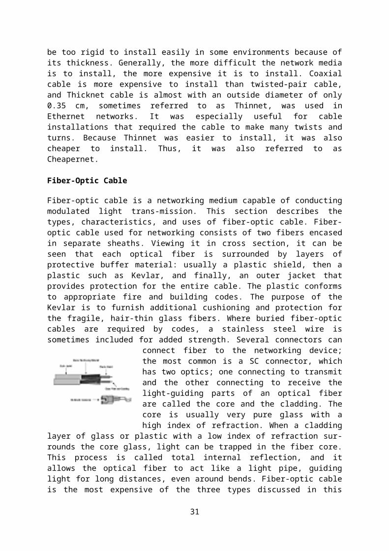
protection for the fragile, hair-thin glass fibers. Where buried fiber-optic cables are required by codes, a stainless steel wire is sometimes included for added strength. Several connectors
can connect fiber to the networking device; the most common is a SC connector, which has two optics; one connecting to transmit and the other connecting to receive the light-guiding parts of an optical fiber are called the core and the cladding. The core is usually very pure glass with a high index of refraction. When a cladding layer of glass or plastic with a low index of refraction surrounds the core glass, light can be trapped in the fiber core. This process is called total internal reflection, and it allows the optical fiber to act like a light pipe, guiding light for long distances, even around bends. Fiber-optic
cable is the most expensive of the three types discussed in this lesson, but it supports higher rate line speeds. Fiber-optic cable does not carry electrical impulses as copper wire does. Instead, signals that represent bits are converted into pulses of light. Two types of fiber-optic cable exist:
Single-mode—Single-mode fiber-optic cable allows only one mode (or wavelength) of light to propagate through the fiber. This type of cable is capable of higher band-width and greater distances than multimode and is often used for campus backbones. Single-mode cable uses lasers as the light-generating method and is more expensive than multimode cable. The maximum cable length of single-mode cable is 60+ km (37+ miles).
Multimode—Multimode fiber-optic cable allows multiple modes of light to propagate through the fiber. Multimode cable is often used for workgroup applications, using light emitting diodes (LEDs) as light-generating devices. The maximum length of multimode cable is 2 km (1.2 miles).
The characteristics of the different media have a significant impact on the speed of data transfer. Although fiber-optic cable is more expensive, it is not susceptible to EMI and is capable of higher data rates than any of the other types of networking media discussed here. Fiber-optic cable is also more secure because it does not emit electrical signals that could be received by external devices.
Wireless Communications
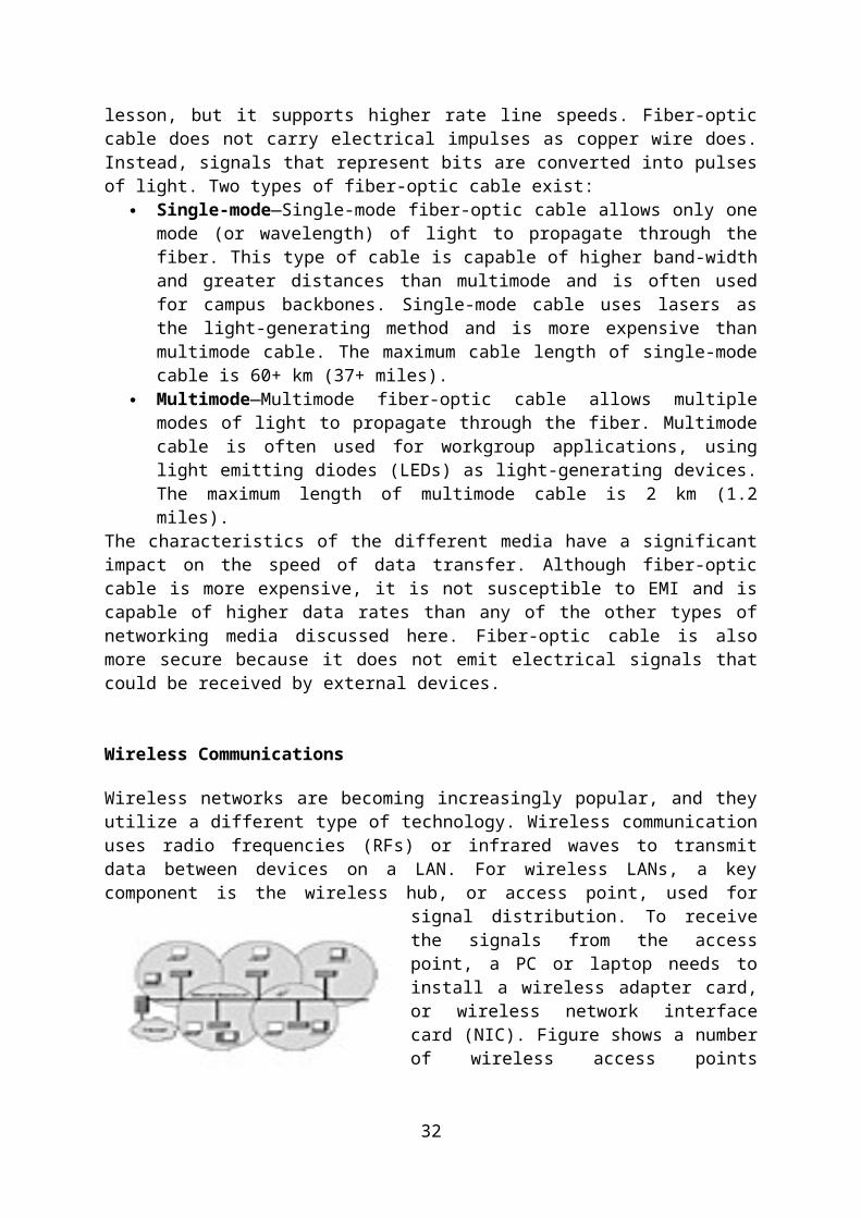
Wireless networks are becoming increasingly popular, and they utilize a different type of technology. Wireless communication uses radio frequencies (RFs) or infrared waves to transmit data between devices on a LAN. For wireless LANs, a key component is the
wireless hub, or access point, used for signal distribution. To receive the signals from the access point, a PC or laptop needs to install a wireless adapter card, or wireless network interface card (NIC). Figure shows a number of wireless access points connected to an Ethernet backbone to provide access to the Internet.
Wireless Access Points
24

Wireless signals are electromagnetic waves that can travel through the vacuum of outer space and through a medium such as air. No physical medium is necessary for wireless signals, making them a versatile way to build a network. They use portions of the RF spectrum to transmit voice, video, and data. Wireless frequencies range from 3 kHz to 300 GHz. The data-transmission rates range from 9 kbps to 54 Mbps. Figure 4-6 shows the electromagnetic spectrum chart.
Electromagnetic Spectrum
Electromagnetic waves are differentiated by their frequency. Low-frequency electro-magnetic waves have a long wavelength (the distance from one peak to the next on the sine wave), while high-frequency electromagnetic waves have a short wavelength. Some common applications of wireless data communication include the following:
Accessing the Internet using a cellular phone Home or business Internet connection over satellite Beaming data between two handheld computing devices Wireless keyboard and mouse for the PC
Another common application of wireless data communication is the wireless LAN (WLAN), which is built in accordance with Institute of Electrical and Electronic Engineers (IEEE) 802.11 standards. WLANs typically use radio waves (for example, 902 MHz), microwaves (for example, 2.4 GHz), and infrared (IR) waves (for example, 820 nm) for communication. Wireless technologies are a crucial part of the future of networking.
25

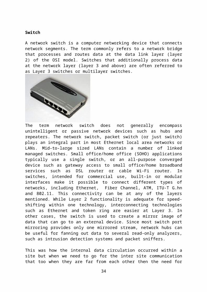
Switch
A network switch is a computer networking device that connects network segments. The term commonly refers to a network bridge that processes and routes data at the data link layer (layer 2) of the OSI model. Switches that additionally process data at the network layer (layer 3 and above) are often referred to as Layer 3 switches or multilayer switches.
The term network switch does not generally encompass unintelligent or passive network devices such as hubs and repeaters. The network switch, packet switch (or just switch) plays an integral part in most Ethernet local area networks or LANs. Mid-to-large sized LANs contain a number of linked managed switches. Small office/home office (SOHO) applications typically use a single switch, or an all-purpose converged device such as gateway access to small office/home broadband services such as DSL router or cable Wi-Fi router. In switches, intended for commercial use, built-in or modular interfaces make it possible to connect different types of networks, including Ethernet, Fiber Channel, ATM, ITU-T G.hn and 802.11. This connectivity can be at any of the layers mentioned. While Layer 2 functionality is adequate for speed-shifting within one technology, interconnecting technologies such as Ethernet and token ring are easier at Layer 3. In other cases, the switch is used to create a mirror image of data that can go to an external device. Since most switch port mirroring provides only one mirrored stream, network hubs can be useful for fanning out data to several read-only analyzers, such as intrusion detection systems and packet sniffers.
This was how the internal data circulation occurred within a site but when we need to go for the inter site communication that too when they are far from each other then the need for router becomes essential as with the help of its VPN (virtual private network) we could easily do that and that too efficiently but too make it more economical its always preferred to go for some service provider.
Routers
Routers are used to tie multiple networks together. For example, you would use a router to connect your networked computers to the Internet and thereby share an Internet connection among many users. The router will act as a dispatcher, choosing the best route for your information to travel so that you receive it quickly.Routers analyze the data being sent over a network, change how it is packaged and send it to another network or over a different type of network. They connect your business to the outside world, protect your information from security threats, and can even decide which computers get priority over others.
26

Depending on your business and your networking plans, you can choose from routers that include different capabilities. These can include functions such as:
o Firewall: specialized software that examines incoming data and protects your business network against attacks
o Virtual Private Network (VPN): A way to allow remote employees to safely access your network remotely
o IP Phone network : Combine your company's computer and telephone network using voice and conferencing technology, to simplify and unify your communications
Now this was the way we made network and connected it with other networks so that our motto of interconnection between different sites was achieved and there was proper flow of the data going on as far that organization was concerned now this was not where all ended as network management was also to be done which include:
Setting up servers running various applications needed for that organization
Installing workstations for that organizations employees
Setting other IT equipments like scanners , printers etc
Software management for that company
IP addressing scheme implemented
Firewall and intrusion protection system
Installation of IP based cameras to monitor entire proceedings at various sites.
27

IP ADDRESSING
One of the most important topics in any discussion of TCP/IP is IP addressing. An IP address is a numeric identifier assigned to each machine on an IP network. It designates the specific location of a device on the network. An IP address is a software address, not a hardware address—the latter is hard-coded on a network interface card (NIC) and used for finding hosts on a local network. IP addressing was designed to allow hosts on one network to communicate with a host on a different network regardless of the type of LANs the hosts are participating in.
IP Terminology
Bit
A bit is one digit, either a 1 or a 0.
Byte
A byte is 7 or 8 bits, depending on whether parity is used.
Octet
An octet, made up of 8 bits, is just an ordinary 8-bit binary number.
Network address
This is the designation used in routing to send packets to a remote network—for example, 10.0.0.0, 172.16.0.0, and 192.168.10.0.
Broadcast address
The address used by applications and hosts to send information to all nodes on a network is called the broadcast address. Examples include 255.255.255.255, which is all networks, all nodes; 172.16.255.255, which is all subnets and hosts on network 172.16.0.0; and 10.255.255.255, which broadcasts to all subnets and hosts on network 10.0.0.0.
The Hierarchical IP Addressing Scheme
An IP address consists of 32 bits of information. These bits are divided into four sections, referred to as octets or bytes, each containing 1 byte (8 bits). IP address can be written using one of three methods:
-Dotted-decimal, as in 172.16.30.56-Binary, as in 10101100.00010000.00011110.00111000-Hexadecimal, as in AC.10.1E.38
28

Network Addressing
The network address uniquely identifies each network. Every machine on the same network shares that network address as part of its IP address. In the IP address 172.16.30.56, for example, 172.16 is the network address. The node address is assigned to, and uniquely identifies, each machine on a network. This part of the address must be unique because it identifies a particular machine—an individual—as opposed to a network, which is a group. This number can also be referred to as a host address.In the sample IP address 172.16.30.56, the 30.56 is the node address. The designers of the Internet decided to create classes of networks based on network size. For the small number of networks possessing a very large number of nodes, they created the rank Class A network. At the other extreme is the Class C network, which is reserved for the numerous networks with a small number of nodes. The class distinction for networks between very large and very small is predictably called the Class B network. Subdividing an IP address into a network and node address is determined by the class designation of one’s network.
Class D: Multicast
Class E: Research
Network Address Range: Class A
The designers of the IP address scheme said that the first bit of the first byte in a Class A network address must always be off, or 0. This means a Class A address must be between 0 and 127 in the first byte, inclusive.
Consider the following network address:0xxxxxxxIf we turn the other 7 bits all off and then turn them all on, we’ll find the Class A range of network addresses:00000000 = 001111111 = 127So, a Class A network is defined in the first octet between 0 and 127, and it can’t be less or more.
29

Network Address Range: Class B
In a Class B network, the RFCs state that the first bit of the first byte must always be turned on but the second bit must always be turned off. If you turn the other 6 bits all off and then all on, you will find the range for a Class B network:10000000 = 12810111111 = 191
So, a Class B network is defined when the first byte is configured from 128 to 191.
Network Address Range: Class C
For Class C networks, the RFCs define the first 2 bits of the first octet as always turned on, but the third bit can never be on. Following the same process as the previous classes, convert from binary to decimal to find the range. Here’s the range for a Class C network:11000000 = 19211011111 = 223So, an IP address that starts at 192 and goes to 223, it is a Class C IP address.
Network Address Ranges: Classes D and E
The addresses from 224 to 255 are reserved for Class D and E networks. Class D (224–239) is used for multicast addresses and Class E (240–255) for scientific purposes.
Reserved IP Addresses
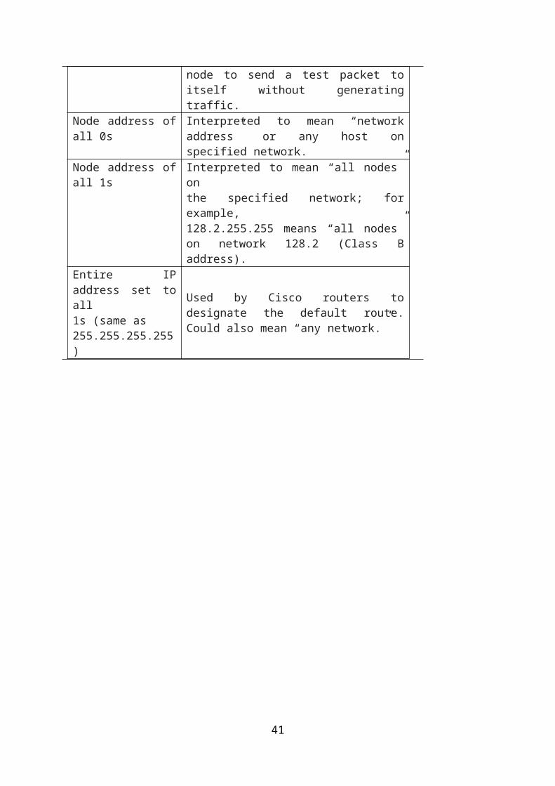
Address FunctionNetwork address of all 0s Interpreted to mean “this network or segment.”
Network address of all 1s
Interpreted to mean “all networks.”
Network 127.0.0.1 Reserved for loopback tests.Designates local node and allow node to send a test packet to itself without generating traffic.
Node address of all 0s Interpreted to mean “network address” or any host on specified network.
Node address of all 1s Interpreted to mean “all nodes” onthe specified network; for example,128.2.255.255 means “all nodes” on network 128.2 (Class B address).
Entire IP address set to all1s (same as255.255.255.255)
Used by Cisco routers to designate the default route. Could also mean “any network.”
30
Class A Addresses
In a Class A network address, the first byte is assigned to the network address and the three remaining bytes are used for the node addresses. The Class A format is as follows:
network.node.node.node
For example, in the IP address 49.22.102.70, the 49 is the network address and 22.102.70 is the node address. Every machine on this particular network would have the distinctive network address of 49.
Class A network addresses are 1 byte long, with the first bit of that byte reserved and the 7 remaining bits available for manipulation (addressing). As a result, the maximum number of Class A networks that can be created are 128. Why? Because the remaining seven bits can be
either a 0 or a 1, thus 27, or 128.
The network address of all 0s (0000 0000) is reserved to designate the default route. Additionally, the address 127, which is reserved for diagnostics, can’t be used either, which means that only the numbers 1 to 126 can be used to designate Class A network addresses. This means the actual number of usable Class A network addresses is 128 minus 2, or 126.
The IP address 127.0.0.1 is used to test the IP stack on an individual node and cannot be used as a valid host address. Each Class A address has 3 bytes (24-bit positions) for the node
address of a machine. This means there are 224—or 16,777,216—unique combinations and, therefore, precisely that many possible unique node addresses for each Class A network. Because node addresses with the two patterns of all 0s and all 1s are reserved, the actual
maximum usable number of nodes for a Class A network is 224 minus 2, which equals 16,777,214.
Class A Valid Host IDs
Here’s an example of how to figure out the valid host IDs in a Class A network address:
All host bits off is the network address: 10.0.0.0.All host bits on is the broadcast address: 10.255.255.255.
The valid hosts are the numbers in between the network address and the broadcast address: 10.0.0.1 through 10.255.255.254.
Class B Addresses
In a Class B network address, the first 2 bytes are assigned to the network address and the remaining 2 bytes are used for node addresses. The format is as follows:
network.network.node.node
For example, in the IP address 172.16.30.56, the network address is 172.16 and the node address is 30.56.
31
With a network address being 2 bytes (8 bits each), there would be 216 unique combinations.But the Internet designers decided that all Class B network addresses should start with the binary digit 1, then 0. This leaves 14 bit positions to manipulate, therefore 16,384 (that is,
214) unique Class B network addresses.
A Class B address uses 2 bytes for node addresses. This is 216 minus the two reserved patterns (all 0s and all 1s), for a total of 65,534 possible node addresses for each Class B network.
Class B Valid Host IDs
All host bits turned off is the network address: 172.16.0.0.All host bits turned on is the broadcast address: 172.16.255.255.
The valid hosts would be the numbers in between the network address and the broadcast address: 172.16.0.1 through 172.16.255.254.
Class C Addresses
The first 3 bytes of a Class C network address are dedicated to the network portion of the address, with only 1 measly byte remaining for the node address. Here’s the format:
network.network.network.node
Using the example IP address 192.168.100.102, the network address is 192.168.100 and the node address is 102.
In a Class C network address, the first three bit positions are always the binary 110. The calculation is as follows: 3 bytes, or 24 bits, minus 3 reserved positions leaves 21 positions.
Hence, there are 221, or 2,097,152, possible Class C networks.
Each unique Class C network has 1 byte to use for node addresses. This leads to 28 or 256, minus the two reserved patterns of all 0s and all 1s, for a total of 254 node addresses for each Class C network.
Class C Valid Host IDs
All host bits turned off is the network ID: 192.168.100.0.All host bits turned on is the broadcast address: 192.168.100.255.
The valid hosts would be the numbers in between the network address and the broadcast address: 192.168.100.1 through 192.168.100.254.
32

SUBNETTING
CHOOSING A CLASS
ADDRESSCLASS
STARTING BITS(FIRST BYTE)
START ADDRESS
FINISH ADDRESS
NETWORKEXITING PER CLASS
HOSTS PER NETWORK
CLASS A 0 0.0.0.0 126.255.255.255
125 16777216
CLASS B 10 128.0.0.0 191.255.255.255
16384 65532
CLASS C 110 192.0.0.0 223.255.255.255
2097152 254
SUNBET MASK = DEFINES NETWORK ID AND HOST ID. AND ALSO CLASS.EX.IP ADD.= 192.168.100.20
SUBNET MASK = 255.255.255.0
MEANS IST, 2nd and 3rd octets are net id and last octet is host id.CLASS A = 255.0.0.0CLASS B = 255.255.0.0CLASS C = 255.255.255.0
For the subnet address scheme to work, every machine on the network must know which part of the host address will be used as the subnet address. This is accomplished by assigning a subnet mask to each machine. A subnet mask is a 32-bit value that allows the recipient of IP packets to distinguish the network ID portion of the IP address from the host ID portion of the IP address. The network administrator creates a 32-bit subnet mask composed of 1s and 0s. The 1s in the subnet mask represent the positions that refer to the network or subnet addresses. Not all networks need subnets, meaning they use the default subnet mask. This is basically the same as saying that a network doesn’t have a subnet address. Table 3.1 shows the default subnet masks for Classes A, B, and C. These default masks cannot change. In other words, you can’t make a Class B subnet mask read 255.0.0.0. If you try, the host will read that address as invalid and usually won’t even let you type it in.
For a Class A network, you can’t change the first byte in a subnet mask; it must read 255.0.0.0 at a minimum. Similarly, you cannot assign 255.255.255.255, as this is all 1s—a broadcast address. A Class B address must start with 255.255.0.0, and a Class C has to start with 255.255.255.0.
33
Class FormatDefault Subnet Mask
A network.node.node.node 255.0.0.0
B network.network.node.node 255.255.0.0
C network.network.network.node 255.255.255.0
PRIVATE IP ADDRESSES OR FREE IP's:-
CLASS A - 10.0.0.0 - 10.255.255.254CLASS B - 172.16.0.0 - 172.31.255.254CLASS C - 192.168.0.0 - 192.168.255.254
INVALID IP ADDRESSES:-
0.0.0.0 and 255.255.255.255
APIPA ADDRESSES (AUTOMATIC PRIVATE IP ADDRESSING)
169.254.0.1 - 169.254.255.254
LOOPBACK ADDRESSES - FOR check ur own NIC
127.0.0.1 - 127.255.255.254
MEDIA COMPARISION
Different types of medium are used for communication purpose. The characteristics of each medium are given below:
Characteristics UTP STP Coaxial Cables Fiber Optic Cables
Bandwidth 10 Mbps-100Mbps
10Mbps-100Mbps
10 Mbps 100Mbps-1Gbps
Maximum cable 100 meters 100 meters 200-500 meters or kilometers
2 km -100 segment
Interference rating
Poor Better than UTP
Better than twistedpair wires
Very good as compared toAny other cable
Installation cost Cheap Costly than UTP
Costly than twistedpair wires
Mostly costly to install
Bend radius 360degrees/ feet
360degrees/ feet
360degrees/ feetor 30 degrees/feet
30 degrees/feet
Security Low Low Low High
34

Variable Length Subnet Masks (VLSMs)
To take one network and create many networks using sub-net masks of different lengths on different types of network designs is called VLSM networking.
Why Bother with VLSM Design?
Suppose, you have just been hired by a new company and need to add on to the existing network. There is no problem with starting over with a new IP address scheme. Should you use a VLSM classless network or a classful network?
Let’s just say you happen to have plenty of address space because you are using the Class A 10.0.0.0 private network address in your corporate environment and can’t even come close to imagining that you’d ever run out of IP addresses. Why would you want to bother with the VLSM design process?
Because by creating contiguous blocks of addresses to specific areas of your network, you can then easily summarize your network and keep route updates with a routing protocol to a minimum. Why would anyone want to advertise hundreds of networks between buildings when you can just send one summary route between buildings and achieve the same result? Summarization, also called Supernetting, provides route updates in the most efficient way possible by advertising many routes in one advertisement instead of individually.
35

TCP/IP SERVICES
TCP/IP
TCP/IP is not a single protocol. It is a suite of protocols. A group of many protocols refers to as TCP/IP.
Some of the important TCP/IP protocols are
TCP : -It is used to transport data from one PC to another.
IP : -It helps in transporting data through an internetwork,i.e.,from one network to another.
FTP (File Transfer Protocol) : -It is used to transfer files from one PC to another. It is areliable protocol widely used in Internet to download/upload files.
TFTP (Trivial File Transfer Protocol) : -It is a load and unreliable protocol used to transfer files.It is faster than FTP.
DNS : -It is used to translate computer names into ip addresses.
DHCP : -It is used to assign ip addresses to computers automatically.
BOOTP (Bootstrap protocol) :-It is used to assign ip address to a client automatically and also used to send an operating system to the client in case of diskless workstations.
HTTP : -It is used to access websites from the Web Server on the client PC.
ARP (Address Resolution Protocol) : -It is used to translate MAC address into ip address.
r - ARP (reverse ARP) :-It is used to translate ip addresses into MAC addresses.
Telnet : -It is used to access a remote computer and to do administrative tasks on it using a commandline interface.
SNMP (Simple Network Management Protocol) : -It is used to analyse and monitor network traffic.
36

INTRODUCTION TO ROUTER
It is an intelligent device. It works on networks layer. It is used for internet work communication, packet switching, packet filtering and path selection. It has no of broadcast and collision domain. By default router does not broadcast. Router understands different topology and protocols. It works on full duplex mode.
ROUTER represents a separate network.
The Network layer (also called layer 3) manages device addressing, tracks the location of devices on the network, and determines the best way to move data, which means that the Network layer must transport traffic between devices that aren’t locally attached. Routers (layer 3 devices) are specified at the Network layer and provide the routing services within an internetwork. It happens like this: First, when a packet is received on a router interface, the destination IP address is checked. If the packet isn’t destined for that particular router, it will look up the destination network address in the routing table. Once the router chooses an exit interface, the packet will be sent to that interface to be framed and sent out on the local network. If the router can’t find an entry for the packet’s destination network in the routing table, the router drops the packet. Two types of packets are used at the Network layer: data and route updates.
Data packets Used to transport user data through the internetwork. Protocols used to support data traffic are called routed protocols; examples of routed protocols are IP and IPv6.
Route update packets Used to update neighboring routers about the networks connected to all routers within the internetwork. Protocols that send route update packets are called routing protocols; examples of some common ones are RIP, RIPv2, EIGRP, and OSPF. Route update packets are used to help build and maintain routing tables on each router.
Network addresses Protocol-specific network addresses. A router must maintain a routing table for individual routing protocols because each routing protocol keeps track of a network with a different addressing scheme (IP, IPv6, and IPX, for example).
3.2
37

Interface The exit interface a packet will take when destined for a specific network.
Metric It is the distance to the remote network. Different routing protocols use different ways of computing this distance
Routers break up broadcast domains, which mean that by default, broadcasts aren’t forwarded. Routers also break up collision domains, but you can also do that using layer 2 (Data Link layer) switches. Because each interface in a router represents a separate network, it must be assigned unique network identification numbers, and each host on the network connected to that router must use the same network number.
A router in an internetwork
o Each router interface is a broadcast domain. Routers break up broadcast domains by default and provide WAN services.
o Routers, by default, will not forward any broadcast or multicast packets.
o Routers use the logical address in a Network layer header to determine the next hop router to forward the packet to.
o Routers can use access lists, created by an administrator, to control security on the types of packets that are allowed to enter or exit an interface.
o Routers can provide layer 2 bridging functions if needed and can simultaneously route through the same interface.
o Routers provide connections between virtual LANs (VLANs).
The term routing is used for taking a packet from one device and sending it through the network to another device on a different network. Routers don’t really care about hosts— they only care about networks and the best path to each network. The logical network address of the destination host is used to get packets to a network through a routed network, and then the hardware address of the host is used to deliver the packet from a router to the correct destination host.
To be able to route packets, a router must know, at a minimum, the following:o Destination addresso Neighbor routers from which it can learn about remote networkso Possible routes to all remote networks.
38

TYPES OF ROUTER MEMORY
ROM:- Rom:- Read Only Memory – Bootstrap/POST Maintains instructions for power-on self test (POST) diagnostics Stores bootstrap program and basic operating system software Mini IOS
EEPROM 1:- Is a type of electronically erasable, programmable ROM. Holds the operating system image (IOS) Allows software to be updated without removing and replacing chips on the
processor Retains content when router is powered down or restarted
Can store multiple versions of IOS software
NVRAM :- Provides storage for the startup configuration file Retains content when router is powered down or restarted Configuration Register
– 16 bit register which decides boot sequence
RAM:- Random Access Memory, also called dynamic RAM (DRAM) Stores routing tables Holds ARP cache Performs packet buffering (shared RAM) Provides temporary memory for the configuration file of the router while the router
is powered on Loses content when router is powered down or restarted
MODES OF ROUTER
39

Router has three main modes of router:-1. User Mode2. Privilege Mode3. Global/Configuration Mode
Global Mode is further classified as:(a.) Router Mode(b.) Line Mode(c.) Interface Mode
40
MODES FUNCTION
USER By default user is in this mode.It is denoted as Router >.
PRIVILEGE This mode is used to check the configuration.It is denoted as Router #
GLOBAL Configurations are done in this mode.It is denoted as Router(config) #
MODES FUNCTION
ROUTER It is denoted asRouter (config-router)#
LINE It is denoted asRouter(config-line) #
INTERFACE It is denoted asRouter(config-if) #
BASIC COMMANDS
Command for user mode to privilege mode- enable
Command for privilege mode to user mode- disable
Command for privilege mode to global- configure terminal
Command for global mode to privilege mode- exit
PRIVILEGE MODE COMMANDS
1. show ip interface brief - for showing ip interfaces in brief2. show running-configuration – for checking running condition of RAM3. show startup-configuration – for checking the status of RAM4. show ip route – for checking routing table5. show version – for checking the status of version6. show interface – for all details of all interfaces present7. show ip protocols – for details of protocols8. show history – display last few commands entered9. show clock – for showing clock10. terminal history size 50 – to change size of number of commands shown in
history to 50.
41

ROUTING AND ROUTING PROTOCOLS
TYPES OF ROUTING
STATIC ROUTINGStatic routing is the simplest form of routing, but it is a manual process and does not work well when the routing information has to be changed frequently or needs to be configured on a large number of routing devices (routers).
DEFAULT ROUTINGDefault routing is used to send packets with a remote destination network not in the routing table to the next-hop router.
DYNAMIC ROUTINGDynamic routing protocols are software applications that dynamically discover network destinations and how to get to them.
There are two classifications of protocols
IGP - Interior Gateway Protocol. The name used to describe the fact that each system on the internet can choose its own routing protocol. RIP and OSPF are interior gateway protocols.
EGP - Exterior Gateway Protocol. Used between routers of different systems. There are two of these, the first having the same name as this protocol description:
42
TYPES OF ROUTING
STATIC ROUTING
DEFAULT ROUTING
DYNAMIC ROUTING

TYPES OF DYNAMIC ROUTING PROTOCOLS
RIP IGRP EIGRP BGP IS-IS OSPF
ROUTING INFORMATION PROTOCOL (RIP)
RIP (Routing Information Protocol)
RIP is a true distance-vector routing protocol. RIP sends the complete routing table out to all active interfaces every 30 seconds. RIP uses hop count to determine the best path to a remote network, but it has a maximum allowable hop count of 15, by default meaning that 16 is deemed unreachable. RIP works well in a small network, but it’s inefficient on large networks with slow WAN links or on networks with a large number of routers installed.
There are two versions of RIP namely RIPv1 and RIPv2. RIPv1 sends classful updates and it sends update on broadcast address 255.255.255.255 whereas RIPv2 can send classless updates also and it uses multicast address 224.0.0.9 to update.
RIP Timers
RIP supports four types of timers as follows:
(a) Update Timer : It is the time interval between the updates exchange by the router to the neighbor routes. It is by default set to 30 sec.
43
(b) Hold Down Timer : It is the time interval which is used to keep the network as active when it is not receiving information about network. By default the hold down timer is 180 seconds.
(c) Invalid Timer : It is the time duration after which router will declare network as down or invalid. It declares the router down or invalid after 180 seconds from the time hello packet was received.
(d) Flush Timer : It is a timer which is used to flush the entry i.e. delete the entry of invalid network from routing table. By default it is 240 seconds.
Drawbacks of RIP
RIP has no knowledge of subnet addressing It takes a long time to stabilize after a router or link failure. Uses more broadcasting than OSPF requiring more network bandwidth.
Open Shortest Path First (OSPF)
OSPF (RFC 1257) is a link state protocol rather than a distance vector protocol. It tests the status of its link to each of its neighbors and sends the acquired information to them. It stabilizes after a route or link failure faster than a distance vector protocol based system. OSPF uses IP directly, not relying on TCP or UDP. OSPF can:
Have routes based on IP type of service (part of IP header message) such as FTP or Telnet.
Support subnets. Assign cost to each interface based on reliability, round trip time, etc. Distribute traffic evenly over equal cost routes. Uses multicasting. Costs for specific hops can be set by administrators. Adjacent routers swap
information instead of broadcasting to all routers.
OSPF (Open Shortest Path First)
This is the open standard routing protocol i.e. any vendor can use this. Suppose if there are different vendor’s router and a very large network is to be employed then only OSPF is the solution. OSPF works by using Dijkstra algorithm also known as shortest path first (SPF) algorithm. OSPF converges very quickly, although not as quickly as EIGRP and it supports equal cost routes to the destination. It has unlimited hop count. It is a link state routing protocol.
Packet Types
44

1) Hello packet : This packet provides dynamic neighbor discovery and maintain neighbor relationships. Hello packets are addressed to 224.0.0.5
2) Link State Advertisement : LSA is used to advertise the network to neighbor.
3) DBD : DBD is database descriptor packet. It sends a list of router IDs from whom the router has an LSA and the current sequence number. This information is used to compare information about the network.
4) LSR : Link State Request follows DBD to ask for any missing LSAs.
5) LSU : Link State Update replies to a link state request with the requested data.
6) LSAck : Link State Acknowledgement confirms receipt of link state information.
Neighborship
Following are the steps which are passed through the formation of neighbors:
1) Blocked : Initially all routers are in blocked state and in this state no information has been received from the neighbor.
2) Init : This state indicates that the router has received a hello packet from its neighbor, but the receiving router’s ID was not included in the hello packet.
3) 2-Way : This state indicates that bi-drectional communication has been established between two routers. In this DR/BDR election takes place.
DR/BDR
In OSPF, in any broadcast link, DR/BDR is elected. DR is known as designated router and BDR is backup designated router. In this protocol all the updates are transferred to DR/BDR in a broadcast link and DR will forward the update to everyone in broadcast link. This decreases the update flooding when there is no DR/BDR routers. When a DR router goes down then BDR takes its place and becomes DR and new BDR is elected. BDR always listen and keeps an eye on DR.
The router which starts first with OSPF enabled will become DR and the second will become BDR. This is by default. If in some case all routers start simultaneously then the router with highest router priority will become the DR. if priority is same, which is same by default, then the router with highest router ID will become DR and second highest will become the BDR. DR/BDR election is on interface basis. Updates to DR/BDR are transmitted on multicast address 224.0.0.5 and DR sends the reply on 224.0.0.6
Exstart State: In this state the master/slave are selected which is temporary only. Master/slave are made for proper communication to establish between routers.Exchange State: In this state the DBD packets are exchanged. First the master sends its dat to
45

slave and slave acknowledges and after that slave transmits and master acknowledges.
Loading State: In this state, the actual exchange of link state information occurs. Alsowhen there is something new in the network the update takes place at this stage only i.e. loading takes place.
Full state: In this state, routers are fully adjacent with each other i.e. neighborship has been established. All the network LSAs are exchanged and the router databases are fully synchronized.
Router ID
Router ID is the unique name of router. It is like IP address only i.e. 32 bit. There are two ways of providing router a router ID viz manually and automatically.
Manually: Providing router the router ID manually, is given by a command which is given under OSPF process as follows:Router(config)#router OSPF <process no.>Router(config-router)#router id <ID as A.B.C.D>
Automatically: If manually router ID is not given then router itself assigns the ID. First it checks the loopbacks. If loopbacks are there then highest loopback address is assigned to the router as router ID. If loopbacks are not present then it checks the active interface and assigns the highest IP as router ID. If there are no active interfaces and loopbacks then OSPF process won’t run.
OSPF Areas
If there are huge number of routers in a network then in OSPF they can be grouped to a particular area. In OSPF each router has full map of a network. So larger the network, larger the map will be and more the processing each router will take. Now that large network can be divided into smaller areas in which every router now keeps the map of those router present in its area.
To communicate between different areas there must be area ‘0’ in between them which is known as backbone area. The routers which connects two areas are known as ABR (area border router). The router which connects different autonomous systems is known ASBR (autonomous system border router). Area is formed on the interface basis.
OSPF Tables
a) Adjancy Table : In this table the list of all the neighbor routers with their router ID is present with whom the adjancy has been established.
b) Database Table : In this table whole topology table is present i.e. the routers which arepresent in a network are stored in this table.
46

c) Forwarding Table : This table is also known as routing table. In this all the best path to routers are stored so that whenever packet comes to a router, the router sees the routing table and forward the packet immediately.
Wild Card Bits
Wild card bits or wild card mask is derived from subnet mask by subtracting subnet mask from 255.255.255.255 e.g. if a subnet mask is 255.255.255.240 then the wild card bit will be 0.0.0.15
Border Gateway Protocol (BGP)
Described by RFC 1267, 1268, and 1497. It uses TCP as a transport protocol. When two systems are using BGP, they establish a TCP connection, then send each other their BGP routing tables. BGP uses distance vectoring. It detects failures by sending periodic keep alive messages to its neighbours every 30 seconds. It exchanges information about reachable networks with other BGP systems including the full path of systems that are between them.
Interior Gateway Routing Protocol (IGRP)
IGRP is a distance vector interior-gateway protocol (IGP). Distance vector routing protocols call for each router to send all or a portion of its routing table in a routing update message at regular intervals to each of its neighbouring routers. As routing information proliferates through the network, routers can calculate distances to all nodes within the internetwork.
Enhanced Interior Gateway Routing Protocol (EIGRP)
The Enhanced Interior Gateway Routing Protocol (EIGRP), referred to as an advanced Distance Vector protocol, offers radical improvements over IGRP. Traditional DV protocols such as RIP and IGRP exchange periodic routing updates with all their neighbors, saving the best distance (or metric) and the vector (or next hop) for each destination. EIGRP differs in that it saves not only the best (least-cost) route but all routes, allowing convergence to be much quicker. Further, EIGRP updates are sent only upon a network topology change; updates are not periodic.It is a cisco proprietary protocol. It supports classless updates. It is a hybrid routing because it has a characteristics of both distance vector and link state protocol. It sends distance vector updates containing information about networks plus the cost of reaching them from the perspective of the advertising router. It has link state characteristics as well – it synchronizes routing tables between neighbors at startup and then sends specific updates only when topology changes occur. EIGRP has a maximum hop count of 255 but by default it is set to 100.It is the only protocol that supports unequal cost load balancing. It uses DUAL (diffusing update algorithm) algorithm to find best path. This protocol also has information about backup path. EIGRP has fastest convergence time. Its hello timer is 5 sec and dead timer is 15 sec.
47
EIGRP has five packet types as:
a) Hello Packet: Hello packet establishes the neighborship and maintains the neighborship.
b) Update Packet : Update packets are used to exchange information about network.
c) Query Packets : These packets are used to send the request to neighbor about network.
d) Reply Packet : It is used to send the response of query packet.
e) Ack Packet : These packets are used to send the acknowledgement for update, query, and reply packet.
EIGRP has three tables to maintain:
1) Neighbor Table : It keeps the list of its neighbors in the neighbor table. This table also contains the neighbors IP address, Interface, SRTT (smooth round trip time), RTO (retransmission time out) timer, and it also contains the uptime of a neighborship. It only trusts the routes coming from a neighbor. If the router who’s entry is not listed in neighbor table, EIGRP will not accept its update.
2) Topology Table : All the routes which are learnt by an EIGRP router are kept in topology table. It contains the backup routes to a destination.
3) Routing Table : It contains the list of best paths for a destination. Only this is the table which is used by router to forward packet for destination. From here the route is taken and the packet is forwarded.
EIGRP metric is Bandwidth, Load, Delay, MTU (maximum transfer unit), and Reliability. By default bandwidth and delay are used.
IS-IS: Intermediate System to Intermediate System Routing Protocol
Intermediate System-to-Intermediate System (IS-IS) is a routing protocol developed by the ISO. It is a link-state protocol where IS (routers) exchange routing information based on a single metric to determine network topology. It behaves similar to Open Shortest Path First (OSPF) in the TCP/IP network.
48
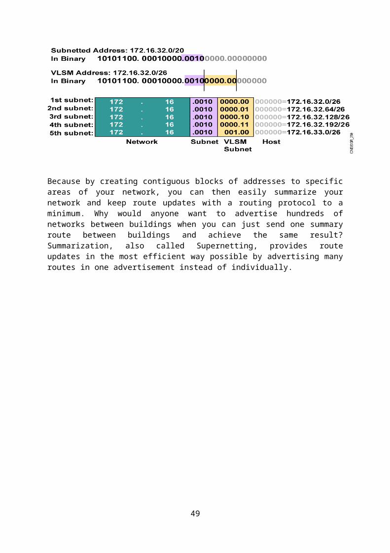
ACL (Access Control List)
Access control list is used to provide the packet filtering function in the network. ACL is used to permit or deny the unwanted packets or they can be used to control that which network will or will not be advertised by dynamic routing protocol.
The packet is always compared with each line of the access list in sequential order.
The packet is compared with lines of the access list only until a match is made. Once the packet matches the condition on a line of the access list, the packet is acted upon and no further comparison takes place.
There is an implicit “deny” at the end of each access list i.e. if a packet doesn’t match the condition on any of the lines in the access list, the packet will be discarded.
There are two main types of access list:1) Standard Access List2) Extended Access List
Standard Access List
Standard IP access list filter network traffic by examining the source IP address in a packet. Standard access lists are created by using the access list numbers 1 to 99 or 1300 to 1999. Access list types are generally differentiated using a number. Based on the number used when the access list is created, the router knows which type of syntax to expect as the list is entered.
The access list is first created and applied on the interface as shown below:
49

Extended Access List
Extended access list checks source IP, destination IP, and protocol like TCP, UDP, IP etc. On the basis of all these things the packet is either permit or deny as per the list created. Extended access list range is 100 to 199 or 2000 to 2699.For best results standard access list should be applied near the destination and extended access list should be applied near the source.The configuration of extended access list is as:
50

Network Address Translation/ Port Address Translation (NAT/PAT)
In computer networking, network address translation (NAT) is the process of
modifying network address information in datagram (IP) packet headers while in transit
across a traffic routing device for the purpose of remapping one IP address space into
another.
Most often today, NAT is used in conjunction with network masquerading (or IP
masquerading) which is a technique that hides an entire IP address space, usually consisting
of private network IP addresses (RFC 1918), behind a single IP address in another, often
public address space. This mechanism is implemented in a routing device that
uses stateful translation tables to map the "hidden" addresses into a single IP address and
readdresses the outgoing Internet Protocol (IP) packets on exit so that they appear to originate
from the router. In the reverse communications path, responses are mapped back to the
originating IP address using the rules ("state") stored in the translation tables. The translation
table rules established in this fashion are flushed after a short period unless new traffic
refreshes their state.
As described, the method enables communication through the router only when the
conversation originates in the masqueraded network, since this establishes the translation
tables. For example, a web browser in the masqueraded network can browse a website
outside, but a web browser outside could not browse a web site in the masqueraded network.
However, most NAT devices today allow the network administrator to configure translation
table entries for permanent use. This feature is often referred to as "static NAT" or port
forwarding and allows traffic originating in the "outside" network to reach designated hosts
in the masqueraded network.
In the mid-1990s NAT became a popular tool for alleviating the problem of IPv4 address
exhaustion. It has become a standard, indispensable feature in routers for home and small-
office Internet connections.
Most systems using NAT do so in order to enable multiple hosts on a private network to
access the Internet using a single public IP address (see gateway). However, NAT breaks the
originally envisioned model of IP end-to-end connectivity across the Internet, introduces
complications in communication between hosts, and affects performance.
NAT obscures an internal network's structure: all traffic appears to outside parties as if it
originated from the gateway machine.
Network address translation involves over-writing the source or destination IP address and
usually also the TCP/UDP port numbers of IP packets as they pass through the router.
Checksums (both IP and TCP/UDP) must also be rewritten as a result of these changes.
51

There are two levels of network address translation.
Basic NAT. This involves IP address translation only, not port mapping.
PAT (Port Address Translation). Also called simply "NAT" or "Network Address Port
Translation, NAPT". This involves the translation of both IP addresses and port numbers.
All Internet packets have a source IP address and a destination IP address. Both or either of
the source and destination addresses may be translated.
Some Internet packets do not have port numbers: for example, ICMP packets. However, the
vast bulk of Internet traffic is TCP and UDP packets, which do have port numbers. Packets
which do have port numbers have both a source port number and a destination port number.
Both or either of the source and destination ports may be translated.
NAT which involves translation of the source IP address and/or source port is called source
NAT or SNAT. This re-writes the IP address and/or port number of the computer which
originated the packet.
NAT which involves translation of the destination IP address and/or destination port number
is called destination NAT or DNAT. This re-writes the IP address and/or port number
corresponding to the destination computer.
SNAT and DNAT may be applied simultaneously to Internet packets.
Full-cone NAT, also known as one-to-one NAT
Once an internal address
(iAddr:iPort) is mapped to an
external address (eAddr:ePort),
any packets from iAddr:iPort will
be sent through eAddr:ePort.
Any external host can send
packets to iAddr:iPort by sending
packets to eAddr:ePort.
52

(Address) restricted cone NAT
Once an internal address
(iAddr:iPort) is mapped to an
external address (eAddr:ePort),
any packets from iAddr:iPort will
be sent through eAddr:ePort.
An external host (hAddr:any) can
send packets to iAddr:iPort by
sending packets to eAddr:ePort
only if iAddr:iPort has previously
sent a packet to hAddr:any.
"Any" means the port number
doesn't matter.
Port-restricted cone NAT
Like an address restricted cone NAT,
but the restriction includes port
numbers.
Once an internal address
(iAddr:iPort) is mapped to an
external address (eAddr:ePort),
any packets from iAddr:iPort will
be sent through eAddr:ePort.
An external host (hAddr:hPort)
can send packets to iAddr:iPort
by sending packets to
eAddr:ePort only if iAddr:iPort
has previously sent a packet to
hAddr:hPort.
Symmetric NAT
Requests from internal IP address
and port combinations to
different external IP address and
port pairs are mapped to the
external NAT address on a
unique port. This also applies to
53

all requests from the same host to
different destinations.
Only an external host that
receives a packet from an internal
host can send a packet back.
NAT and TCP/UDP
"Pure NAT", operating on IP alone, may or may not correctly parse protocols that are totally
concerned with IP information, such as ICMP, depending on whether the payload is
interpreted by a host on the "inside" or "outside" of translation. As soon as the protocol stack
is climbed, even with such basic protocols as TCP and UDP, the protocols will break unless
NAT takes action beyond the network layer.
The major transport layer protocols, TCP and UDP, have a checksum that covers all the data they carry, as well as the TCP/UDP header, plus a "pseudo-header" that contains the source and destination IP addresses of the packet carrying the TCP/UDP header. For an originating NAT to successfully pass TCP or UDP, it must recompute the TCP/UDP header checksum based on the translated IP addresses, not the original ones, and put that checksum into the TCP/UDP header of the first packet of the fragmented set of packets. The receiving NAT must recompute the IP checksum on every packet it passes to the destination host, and also recognize and recompute the TCP/UDP header using the retranslated addresses and pseudo-header. This is not a completely solved problem. One solution is for the receiving NAT to reassemble the entire segment and then recompute a checksum calculated across all packets.
STATIC NAT
Static NAT is a simple one-to-one mapping of private and public addresses. This is required to support inbound connections from your public network into your private network. For each local address defined, there has to be an associated globally unique address.
54

Dynamic NAT
Dynamic NAT can only be used to establish connections from within the private network out to the public network. A pool of network addresses is maintained and used when an outbound connection is made. Each connection is assigned a unique public address. The maximum number of simultaneous connections is equal to the number of public addresses in the pool. This is similar to a one-to-one correspondence between addresses. Dynamic NAT allows you to communicate with the Internet through a dynamic NAT address. The figure below illustrates Dynamic NAT.
55

DRAWBACKS
Hosts behind NAT-enabled routers do not have end-to-end connectivity and cannot
participate in some Internet protocols. Services that require the initiation of TCP connections
from the outside network, or stateless protocols such as those using UDP, can be disrupted.
Unless the NAT router makes a specific effort to support such protocols, incoming packets
cannot reach their destination. Some protocols can accommodate one instance of NAT
between participating hosts ("passive mode" FTP, for example), sometimes with the
assistance of an application-level gateway, but fail when both systems are separated from the
Internet by NAT. Use of NAT also complicates tunneling protocols such as IPsec because
NAT modifies values in the headers which interfere with the integrity checks done
by IPsec and other tunneling protocols.
End-to-end connectivity has been a core principle of the Internet, supported for example by
the Internet Architecture Board. Current Internet architectural documents observe that NAT is
a violation of the End-to-End Principle, but that NAT does have a valid role in careful design.
56

There is considerably more concern with the use of IPv6 NAT, and many IPv6 architects
believe IPv6 was intended to remove the need for NAT.
Because of the short-lived nature of the stateful translation tables in NAT routers, devices on
the internal network lose IP connectivity typically within a very short period of time unless
they implement NAT keep-alive mechanisms by frequently accessing outside hosts. This
dramatically shortens the power reserves on battery-operated hand-held devices and has
thwarted more widespread deployment of such IP-native Internet-enabled devices.
BENFITS
The primary benefit of IP-masquerading NAT is that it has been a practical solution to the
impending exhaustion of IPv4 address space. Even large networks can be connected to the
Internet with as little as a single IP address. The more common arrangement is having
machines that require end-to-end connectivity supplied with a routable IP address, while
having machines that do not provide services to outside users behind NAT with only a few IP
addresses used to enable Internet access.
Some have also called this exact benefit a major drawback, since it delays the need for the
implementation of IPv6
57

SWITCHING BASICS
Network Interface Card
A network interface card, network adapter, network interface controller (NIC), or LAN adap-ter is a computer hardware component designed to allow computers to communicate over a computer network. It is both an OSI layer 1 (physical layer) and layer 2 (data link layer) device, as it provides physical access to a networking medium and provides a low-level addressing system through the use of MAC addresses.
Various functions which a switch performs:-
Address learning Layer 2 switches and bridges remember the source hardware address of each frame received on an interface, and they enter this information into a MAC database called a forward/filter table.
Forward/filter decisions When a frame is received on an interface, the switch looks at the destination hardware address and finds the exit interface in the MAC database. The frame is only forwarded out the specified destination port.
Loop avoidance If multiple connections between switches are created for redundancy purposes, network loops can occur. Spanning Tree Protocol (STP) is used to stop network loops while still permitting redundancy.
Address LearningWhen a switch is first powered on, the MAC forward/filter table is empty, as shown in figure.
Empty forward/filter table on a switchMAC Forward/Filter Table
E0/0: E0/1: E0/2: E0/3:
58

Host A Host B Host C Host D
When a device transmits and an interface receives a frame, the switch places the frame’s source address in the MAC forward/filter table, allowing it to remember which interface the sending device is located on. The switch then has no choice but to flood the network with this frame out of every port except the source port because it has no idea where the destination device is actually located. If a device answers this flooded frame and sends a frame back, then the switch will take the source address from that frame and place that MAC address in its database as well, associating this address with the interface that received the frame. Since the switch now has both of the relevant MAC addresses in its filtering table, the two devices can now make a point-to-point connection. The switch doesn’t need to flood the frame as it did the first time because now the frames can and will be forwarded only between the two devices. This is exactly the thing that makes layer 2 switches better than hubs. In a hub network, all frames are forwarded out all ports every time— no matter what. Following figure shows the processes involved in building a MAC database.
How switches learn hosts’ locations
MAC Forward/Filter Table
E0/0: 0000.8c01.000AE0/1: 0000.8c01.000BE0/2:E0/3:
59
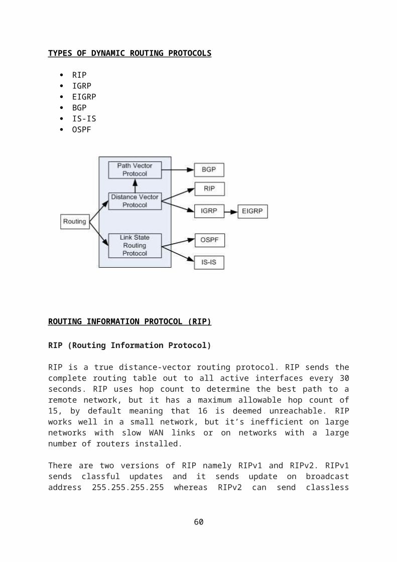
Host A sends a frame to Host B. Host A’s MAC address is 0000.8c01.000A;Host B’s MAC address is 0000.8c01.000B.
The switch receives the frame on the E0/0 interface and places the source address in the MAC address table. Since the destination address is not in the MAC database, the frame is forwarded out all interfaces—except the source port. Host B receives the frame and responds to Host A. The switch receives this frame on interface E0/1 and places the source hardware address in the MAC database. Host A and Host B can now make a point-to-point connection and only the two devices will receive the frames. Hosts C and D will not see the frames, nor are their MAC addresses found in the database because they haven’t yet sent a frame to the switch. If Host A and Host B don’t communicate to the switch again within a certain amount of time, the switch will flush their entries from the database to keep it as current as possible.
Forward/Filter Decisions
When a frame arrives at a switch interface, the destination hardware address is compared to the forward/filter MAC database. If the destination hardware address is known and listed in the database, the frame is only sent out the correct exit interface. The switch doesn’t transmit the frame out any interface except for the destination interface. This preserves bandwidth on the other network segments and is called frame filtering. But if the destination hardware address is not listed in the MAC database, then the frame is flooded out all active interfaces except the interface the frame was received on. If a device answers the flooded frame, the MAC database is updated with the device’s location (interface). If a host or server sends a broadcast on the LAN, the switch will flood the frame out all active ports except the source port by default. Remember, the switch creates smaller collision domains, but it’s still one large broadcast domain by default.
Forward/filter tableSwitch#sh mac address-table1 0005.dccb.d74b Fa0/41 000a.f467.9e80 Fa0/51 000a.f467.9e8b Fa0/6
60
Since Host A’s MAC address is not in the forward/filter table, the switch will add the source address and port to the MAC address table and then forward the frame to Host D. If Host D’sMAC address was not in the forward/filter table, the switch would have flooded the frame out all ports except for port Fa0/3.
Now let’s take a look at the output of a show mac address-table:
Switch#sh mac address-tableVlan
Mac Address Type Ports
1 0005.dccb.d74b DYNAMIC Fa0/1
1 000a.f467.9e80 DYNAMIC Fa0/3
1 000a.f467.9e8b DYNAMIC Fa0/4
1 000a.f467.9e8c DYNAMIC Fa0/3
1 0010.7b7f.c2b0 DYNAMIC Fa0/3
1 0030.80dc.460b DYNAMIC Fa0/3
1 0030.9492.a5dd DYNAMIC Fa0/1
1 00d0.58ad.05f4 DYNAMIC Fa0/1
Loop Avoidance
Redundant links between switches are a good idea because they help prevent complete network failures in the event one link stops working. This is because frames can be flooded down all redundant links simultaneously, creating network loops as well as other evils. Here’s a list of some of the ugliest problems:
If no loop avoidance schemes are put in place, the switches will flood broadcasts endlessly throughout the internetwork. This is sometimes referred to as a broadcast storm.
61
Broadcast storm
SPANNING TREE PROTOCOL (STP)
STP is a bridge-to-bridge protocol used to maintain a loop-free network. STP establishes a root bridge, a root port, and designated ports. With STP, the root bridge has the lowest bridge ID, which is made up of the bridge’s
priority and MAC address. With STP, ports transition through four states: blocking, listening, learning, and
forwarding. If a change occurs to the network topology, STP maintains connectivity by
transitioning some blocked ports to the forwarding state. RSTP significantly speeds the recalculation of the spanning tree when the network
topology changes.
Spanning-Tree Operation
• One root bridge per network• One root port per non-root bridge• One designated port per segment• Non-designated ports are unused
62
63

VLANS (Virtual LANs)
A VLAN permits a group of users to share a common broadcast domain regardless of their physical location in the internetwork. VLAN improve performance and security in switched networks.
A Catalyst switch operates in a network like a traditional bridge. Each VLAN configured on the switch implements address learning, forwarding/filtering decisions, and loop avoidance mechanisms.
Ports belonging to a VLAN are configured with a membership mode that determines to which VLAN they belong. Catalyst switches support two VLAN membership modes: static and dynamic.
The IEEE 802.1Q protocol is used to transport frames for multiple VLANs between switches and routers, and for defining VLAN topologies.
64

WAN (Wide Area Network) and Protocols involved
Below figures shows the different WAN connection types that can be used to connect distant devices.
WAN connection types
Synchronous serial
Here’s a list explaining the different WAN connection types:
Leased lines These are usually referred to as a point-to-point or dedicated connection. A leased line is a pre-established WAN communications path that goes from the CPE through the DCE switch, then over to the CPE of the remote site. The CPE enables DTE networks to communicate at any time with no cumbersome setup procedures to muddle through before transmitting data.
When you’ve got plenty of cash, this is really the way to go because it uses synchronous serial lines up to 45Mbps. HDLC and PPP encapsulations are frequently used on leased lines.
Circuit switching When you hear the term circuit switching, think phone call. The big advantage is cost—you only pay for the time you actually use. No data can transfer before an end-to-end connection is established. Circuit switching uses dial-up modems or ISDN and is used for low-bandwidth data transfers.
Packet switching This is a WAN switching method that allows you to share bandwidth with other companies to save money. Packet switching can be thought of as a network that’s designed to look like a leased line yet charges you more like circuit switching. But less cost isn’t always better—there’s definitely a downside: If you need to transfer data constantly, just forget about this option. Instead, get yourself a leased line. Packet switching will only work
65

for you if your data transfers are the bursty type—not continuous. Frame Relay and X.25 are packet-switching technologies with speeds that can range from 56Kbps up to T3 (45Mbps).
Frame Relay A packet-switched technology that made its debut in the early 1990s, Frame Relay is a high-performance Data Link and Physical layer specification. It’s pretty much a successor to X.25, except that much of the technology in X.25 used to compensate for physical errors (noisy lines) has been eliminated. An upside to Frame Relay is that it can be more cost effective than point-to-point links, plus it typically runs at speeds of 64Kbps up to 45Mbps (T3). Another Frame Relay benefit is that it provides features for dynamic bandwidth allocation and congestion control.
HDLC High-Level Data-Link Control (HDLC) was derived from Synchronous Data Link Control (SDLC), which was created by IBM as a Data Link connection protocol. HDLC works at the Data Link layer and creates very little overhead compared to LAPB. It wasn’t intended to encapsulate multiple Network layer protocols across the same link—the HDLC header doesn’t contain any identification about the type of protocol being carried inside the HDLC encapsulation. Because of this, each vendor that uses HDLC has its own way of identifying the Network layer protocol, meaning each vendor’s HDLC is proprietary with regard to its specific equipment.
PPP Point-to-Point Protocol (PPP) is a pretty famous, industry-standard protocol. Because all multiprotocol versions of HDLC are proprietary, PPP can be used to create point-to-point links between different vendors’ equipment. It uses a Network Control Protocol field in the Data Link header to identify the Network layer protocol and allows authentication and multi-link connections to be run over asynchronous and synchronous links.
66

IP Version-6
Internet Protocol version 6 (IPv6) is a version of the Internet Protocol that is designed to succeed IPv4, the first publicly used implementation, which is still in dominant use currently. It is an Internet Layer protocol for packet-switched internetworks. The main driving force for the redesign of Internet Protocol is the foreseeable IPv4 address exhaustion.IPv6 has a vastly larger address space than IPv4. This results from the use of a 128-bit address, whereas IPv4 uses only 32 bits. The new address space thus supports 2128
(about 3.4×1038) addresses. This expansion provides flexibility in allocating addresses and routing traffic and eliminates the primary need for network address translation (NAT), which gained widespread deployment as an effort to alleviate IPv4 address exhaustion.
IPv6 also implements new features that simplify aspects of address assignment (stateless
address autoconfiguration) and network renumbering (prefix and router announcements)
when changing Internet connectivity providers. The IPv6 subnet size has been standardized
by fixing the size of the host identifier portion of an address to 64 bits to facilitate an
automatic mechanism for forming the host identifier from Link Layer media addressing
information (MAC address).
IPv4 exhaustion
Estimates of the time frame until complete exhaustion of IPv4 addresses varied widely. In
2003, Paul Wilson (director of APNIC) stated that, based on then-current rates of
deployment, the available space would last for one or two decades. In September 2005, a
report by Cisco Systems suggested that the pool of available addresses would dry up in as
little as 4 to 5 years. As of May 2009, a daily updated report projected that the IANA pool of
unallocated addresses would be exhausted in June 2011, with the various Regional Internet
Registries using up their allocations from IANA in March 2012. There is now consensus
among Regional Internet Registries that final milestones of the exhaustion process will be
passed in 2010 or 2011 at the latest, and a policy process has started for the end-game and
post-exhaustion era.
Features and Differences From IPv4
In most regards, IPv6 is a conservative extension of IPv4. Most transport- and application-
layer protocols need little or no change to operate over IPv6; exceptions are application
protocols that embed internet-layer addresses, such as FTP or NTPv3.
IPv6 specifies a new packet format, designed to minimize packet-header processing. Since
the headers of IPv4 packets and IPv6 packets are significantly different, the two protocols are
not interoperable.
67

Larger address space
The most important feature of IPv6 is a much larger address space than that of IPv4:
addresses in IPv6 are 128 bits long, compared to 32-bit addresses in IPv4.
An illustration of an IP address (version 6), in hexadecimal and binary.
The very large IPv6 address space supports a total of 2128 (about 3.4×1038) addresses—or
approximately 5×1028 (roughly 295) addresses for each of the roughly 6.8 billion (6.8×10⁹)
people alive in 2010.
the longer addresses allow a better, systematic, hierarchical allocation of addresses and
efficient route aggregation. With IPv4, complex Classless Inter-Domain Routing (CIDR)
techniques were developed to make the best use of the small address space. Renumbering an
existing network for a new connectivity provider with different routing prefixes is a major
effort with IPv4. With IPv6, however, changing the prefix announced by a few routers can in
principle renumber an entire network since the host identifiers (the least-significant 64 bits of
an address) can be independently self-configured by a host.
The size of a subnet in IPv6 is 264 addresses (64-bit subnet mask), the square of the size of the
entire IPv4 Internet. Thus, actual address space utilization rates will likely be small in IPv6,
but network management and routing will be more efficient because of the inherent design
decisions of large subnet space and hierarchical route aggregation.
IPv6 Addressing and Expressions
Now we will understand how IP addresses are structured and used. We have already read about the fact that at 128 bits, an IPv6 address is much larger than an IPv4 address. Because of this, as well as the new ways the addresses can be used, it is believed that IPv6 will be more complicated to manage. But it is not true. Following is a figure which has a sample IPv6 address broken down into sections.
68
Shortened Expression
There are few tricks to help rescue us when writing these long addresses. For one thing, we can actually leave out parts of the address to abbreviate it, but to get away with doing that we have to follow a couple of rules.First, we can drop any leading zeros in each of the individual blocks. After we do that, the sample address from earlier would then look like this:2001:db8:3c4d:12:0:0:1234:56abInterface ID2001:0db8:3c4d:0012:0000:0000:1234:56abGlobal prefix Subnet
Again referring to our sample address, we can remove the two blocks of zeros by replacing them with double colons, like this:2001:db8:3c4d:12:: 1234:56abWe replaced the blocks of all zeros with double colons. So if the address has four blocks of zeros and each of them were separated, we just don't get to replace them all; the rule is that we can only replace one contiguous block with double colon.For example:2001:0000:0000:0012:0000:0000:1234:56abAnd we just can’t do this:2001::12::1234:56ab
Instead, this is the best that we can do:2001::12:0:0:1234:56abThe reason why the above example is our best shot is that if we remove two sets of zeros, the device looking at the address will have no way of knowing where the zeros go back in. Basically, the router would look at the incorrect address and say, “Well, do I place two blocks into the first set of double colons and two into the second set, or do I place three blocks into the first set and one block into the second set?” And on and on it would go because the information the router needs just isn’t there.
Address Types
We’re all familiar with IPv4’s unicast, broadcast, and multicast addresses that basically define who or at least how many other devices we’re talking to. Broadcasts, as we know, have been eliminated in IPv6 because of their cumbersome inefficiency.So let’s find out what each of these types of IPv6 addressing and communication methods do for us.
Unicast
Packets addressed to a unicast address are delivered to a single interface. For load balancing, multiple interfaces can use the same address. There are a few different types of unicast addresses, but we don’t need to get into that here.
Global unicast addresses
These are your typical publicly routable addresses, and they’re the same as they are in IPv4.
69

Link-local addresses
These are like the private addresses in IPv4 in that they’re not meant to be routed. Think of them as a handy tool that gives you the ability to throw a temporary LAN together for meetings or for creating a small LAN that’s not going to be routed but still needs to share and access files and services locally.
Unique local addresses
These addresses are also intended for non-routing purposes, but they are nearly globally unique, so it’s unlikely you’ll ever have one of them overlap. Unique local addresses were designed to replace site-local addresses, so they basically do almost exactly what IPv4 private addresses do—allow communication throughout a site while being routable to multiple local networks. Site-local addresses were denounced as of September 2004.
Multicast
Again, same as in IPv4, packets addressed to a multicast address are delivered to all interfaces identified by the multicast address. Sometimes people call them one-to-many addresses. It’s really easy to spot a multicast address in IPv6 because they always start with FF.
Anycast
Like multicast addresses, an anycast address identifies multiple interfaces, but there’s a big difference: the anycast packet is only delivered to one address—actually, to the first one it finds defined in terms of routing distance. And again, this address is special because you can apply a single address to more than one interface. You could call them one-to-one-of many addresses, but just saying “anycast” is a lot easier.
Special Addresses
There are a plenty of special, reserved addresses in IPv6 they are there in IPv4. Let’s go over them now.They’re all special or reserved for specific use, but unlike IPv4, IPv6 gives us a galaxy of addresses, so reserving a few here.
0:0:0:0:0:0:0:0
Equals ::. This is the equivalent of IPv4’s 0.0.0.0, and is typically the source address of a host when you’re using stateful configuration.
0:0:0:0:0:0:0:1
Equals ::1. The equivalent of 127.0.0.1 in IPv4.
70

0:0:0:0:0:0:192.168.100.1
This is how an IPv4 address would be written in a mixed IPv6/IPv4 network environment.
2000::/3
The global unicast address range.
FC00::/7
The unique local unicast range.
FE80::/10
The link-local unicast range.
FF00::/8
The multicast range.
3FFF:FFFF::/32
Reserved for examples and documentation.
2001:0DB8::/32
Also reserved for examples and documentation.
2002::/16
Used with 6to4, which is the transition system—the structure that allows IPv6 packets to be transmitted over an IPv4 network without the need to configure explicit tunnels.
71

Wi-Fi
Wi-Fi is the name for the popular wireless networking technology that uses radio waves to provide wireless high-speed Internet and network connections. The Wi-Fi Alliance, the organization that owns the Wi-Fi (registered trademark) term specifically defines Wi-Fi as any "wireless local area network (WLAN) products that are based on the Institute of Electrical and Electronics Engineers' (IEEE) 802.11 standards."
The deregulation of certain radio-frequencies for unlicensed spread spectrum deployment enabled the development of Wi-Fi products, Wi-Fi's onetime competitor HomeRF, Bluetooth, and many other products such as some types of cordless telephones.
The inventors initially intended to use the technology for cashier systems; the first wireless products were brought on the market under the name WaveLAN with raw data rates of 1 Mbit/s and 2 Mbit/s.
Below are some basic facts and pieces of information related to Wi-Fi which will help you
understand Wi-Fi much better and easier.
1. Wi-Fi is a wireless technology that lets digital devices such as PC’s, laptops,
mobile phones to connect and access internet through a router without any
physical association with the wired network(LAN).Interestingly,’Wireless
Fidelity’,as such does not mean anything.It was actually a branding strategy
by the governing Alliance to make their service a bit more catchy and “Hi-Fi”.
2. Wi-Fi hotspots are the access points through which wireless internet is
accessed. Restaurants, coffee-shops, food joints offer free hotspots within their
premises as a mode of attraction. More hotspots correspond to more coverage
and heavy usage support(higher bandwidth support).
3. To establish a Wi-Fi connectivity, the two primary conditions are Wireless
adapter at user’s end(within the laptop or PC) and a Wi-Fi router(externally
placed).Most of new laptops and desktop computers come with built-in
wireless adapter.
4. Wi-Fi networks are very limited in range. A typical Wi-Fi router might have a
range of 30 m(~100 ft) indoor and 90 m(295 ft) outdoor. Range also varies
with selected frequency band. Wi-Fi in the 2.4 GHz frequency band has
slightly better range than Wi-Fi in the 5 GHz frequency band.
5. Wi-Fi is much more prone to security abuse than wired LAN.As the level of
openness is quite high, Wi-Fi’s encryption methods face continuous failure in
front of easily available softwares such as Aircrack. This is the reason why
private Wi-Fi networks prefer employing ‘Whitelist IP Usage’ only.
72

Initially, Wi-Fi was used in place of only the 2.4GHz 802.11b standard, however the Wi-Fi Alliance has expanded the generic use of the Wi-Fi term to include any type of network or WLAN product based on any of the 802.11 standards, including 802.11b, 802.11a, dual-band, and so on, in an attempt to stop confusion about wireless LAN interoperability.
Wi-Fi works with no physical wired connection between sender and receiver by using radio frequency (RF) technology, a frequency within the electromagnetic spectrum associated with radio wave propagation. When an RF current is supplied to an antenna, an electromagnetic field is created that then is able to propagate through space. The cornerstone of any wireless network is an access point (AP). The primary job of an access point is to broadcast a wireless signal that computers can detect and "tune" into. In order to connect to an access point and join a wireless network, computers and devices must be equipped with wireless network adapters
Wi-Fi is supported by many applications and devices including video game consoles, home networks, PDAs, mobile phones, major operating systems, and other types of consumer electronics. Any products that are tested and approved as "Wi-Fi Certified" (a registered trademark) by the Wi-Fi Alliance are certified as interoperable with each other, even if they are from different manufacturers. For example, a user with a Wi-Fi Certified product can use any brand of access point with any other brand of client hardware that also is also "Wi-Fi Certified". Products that pass this certification are required to carry an identifying seal on their packaging that states "Wi-Fi Certified" and indicates the radio frequencyband used (2.5GHz for 802.11b, 802.11g, or 802.11n, and 5GHz for 802.11a).
73

Wireless Technology Standards
Because there are multiple technology standards for wireless networking, it pays to do your homework before buying any equipment. The most common wireless technology standards include the following:
802.11b: The first widely used wireless networking technology, known as 802.11b (more commonly called Wi-Fi), first debuted almost a decade ago, but is still in use.
802.11g: In 2003, a follow-on version called 802.11g appeared offering greater performance (that is, speed and range) and remains today's most common wireless networking technology.
802.11n: Another improved standard called 802.11n is currently under development and is scheduled to be complete in 2009. But even though the 802.11n standard has yet to be finalized, you can still buy products based on the draft 802.11n standard, which you will be able to upgrade later to the final standard.
74

All of the Wi-Fi variants (802.11b, g and n products) use the same 2.4 GHz radio frequency, and as a result are designed to be compatible with each other, so you can usually use devices based on the different standards within the same wireless network. The catch is that doing so often requires special configuration to accommodate the earlier devices, which in turn can reduce the overall performance of the network. In an ideal scenario you'll want all your wireless devices, the access point and all wireless-capable computers, to be using the same technology standard and to be from the same vendor whenever possible.
A General Misconception
A common misconception is that the term Wi-Fi is short for "wireless fidelity ," however this is not the case. Wi-Fi is simply a trademarked term meaning IEEE 802.11x
75

COMMANDS TO SET PASSWORDS ON A ROUTER
To set password on privilege mode:-
Router(config)#enable password daviet
(In encrypted form),
Router(config)#enable secret daviet
To set password on console port:-
Router(config)# line console 0
Router(config-line)#password daviet
Router(config-line)#login
To set password on telnet port:-
Router(config)#line vty 0 4
Router(config-line)#password daviet
To encrypt all the passwords:-
Router(config)#service password encryption
HOW TO BREAK PASSWORD ON A ROUTER
Sometimes the user forgets the password set by him on a router. To avoid such inconvenience in the use of routers, below is given the method to break the password on a router.
As we know that, when a router boots up, it takes all of the previous data from its non-volatile memory which flows in the following way:
76

This is due to the default registered value (i.e, 0x2102) being provided by Cisco to the router while manufacturing it.
If we change this registered value from 0x2102 to 0x2142, then the router while booting up will not demand any passwords being set up previously by the user because now it doesn’t takes the data present in NVRAM.
Commands required:-
While booting up, Press Ctrl+ Pause Break - to switch from USER MODE to ROMMOM MODE.
Rommon>confreg 0x2142
Rommon>reset
Router>enable
Router#configure terminal
Router(config)#copy startup-config running-config
Now,all the data from startup configuration has got copied in the running configuration. Thus, now we can set up cancel all previous passwords and set up new passwords.
Now, we have to follow the same procedure to again change the registered value from 0x2142 to 0x2102 so that the router follows its previous method of booting up.
Thus, now we have canceled the previous passwords on the router and set up new ones without knowing the previous passwords.
77

ROUTER CONFIGURATION
1 Configure routers2 Access Routers through Telnet3 Security4 Wi-Fi5 Switching database(vlan database)6 Trunking7 Firewall8 Configuration of routers through Propriety protocol’s(eigrp vlsm)
HOW TO START CONFIGURE ROUTER
78

CONFIGURE ROUTERS
To configure router first time through HyperTerminal using rollover cable Router configuration process commands-:
1. Start the HyperTerminal .exe program (hypertrm.exe). Click on START, then ACCESSORIES, then COMMUNICATIONS, then HYPERTERMINAL, then chose the HyperTerminal entry that does not have an .ht extension.
2. This brings up this dialog. Enter a Name (like 'Direct-Com-1)Chose an ICON - whatever you wishClick OK
3. This dialog then appears. Click the selection arrow on the "Connect using" listbox, and select the COM port your modem is connected to-not the modemname. When you select the COM port, the phone number to dial boxes are grayed.Click OK
79

4. The COM port properties box comes up. For 56k modems, make sure that you set the Bits per second to 2400
The other defaults shown here are correctClick OK
5. You now get the HyperTerminal window where you are able to control your modem with commands.
80

FUTURE SCOPE
Here are some examples of the skills students will be able to perform after completing CCNA course:
81

BIBLIOGRAPHY
Books:-
Stevens W Richard., “TCP/IP Illustrated Volume - I”Pearson Education, Second Edition.Strebe Mathew, Tata McGraw Hill, Seventh EditionCCNA: Cisco Certified Networking Associate, Study Guide, Todd LemmleNetworking Essentials Module-III, JETKING Curriculum.
Sites:-
www.4shared.com
www.rapidshare.com
www.about.com
http://en.wikipedia.org/wiki/
82