ccna (200 - 125) - atnedu.lk · ccna (200 - 125) page 1 of 89 atn education copy rights @ 2018....
TRANSCRIPT

CCNA
(200 - 125)
Page 1 of 89 ATN Education copy rights @ 2018

CCNA
(200 - 125)
Page 2 of 89 ATN Education copy rights @ 2018
Contents CISCO DEVICE SYMBOLS ....................................................................................................................... 6
Cisco System History ................................................................................................................................ 7
Cisco Career Certification ......................................................................................................................... 7
The Network ................................................................................................................................................. 7
Network Devices ................................................................................................................................... 8
Collision Domain ...................................................................................................................................... 9
Broadcast Domain ..................................................................................................................................... 9
Types of Networks .................................................................................................................................. 10
LAN (Local Area Network) ................................................................................................................ 10
WAN (Wide Area Network) ............................................................................................................... 10
MAN (Metropolitan Area Network) ................................................................................................... 10
TAN (Tiny Area Network) ................................................................................................................. 10
CAN (Campus Area Network) ............................................................................................................ 10
SAN (Storage Area Network) ............................................................................................................. 10
PAN (Personal Area Network) ........................................................................................................... 10
HAN (Home Area Network) ............................................................................................................... 10
Network Topology .................................................................................................................................. 10
Telecommunications methods ................................................................................................................ 11
Internet Protocol (IP) Addressing ........................................................................................................... 11
Versions of IP address......................................................................................................................... 12
IP Types .................................................................................................................................................. 13
IP Ranges ................................................................................................................................................ 13
IP Scopes ................................................................................................................................................. 14
MAC Address (Media Access Control) .................................................................................................. 14
Subnetting ............................................................................................................................................... 15
IPv4 subnetting ................................................................................... Error! Bookmark not defined.
Subnet Mask ........................................................................................................................................ 16
Router Booting Process ........................................................................................................................... 18
Basic Command-line Interface................................................................................................................ 19
Troubleshooting and Show commands ................................................................................................... 20
Secure CISCO Router and Switch .......................................................................................................... 21
Cisco Discovery Protocol (CDP) ............................................................................................................ 22

CCNA
(200 - 125)
Page 3 of 89 ATN Education copy rights @ 2018
Link Layer Discovery protocol (LLDP) /IEEE 802.1AB ....................................................................... 23
Trivially File Transfer Protocol (TFTP) ................................................................................................. 23
Cabling .................................................................................................................................................... 24
Network Technician Tool kits ................................................................................................................ 25
Network Reference model .......................................................................................................................... 26
Open System Interconnecting ................................................................................................................. 26
Protocol data unit (PDUs) ................................................................................................................... 27
Switching ................................................................................................................................................ 33
Address Resolution Protocol (ARP) ................................................................................................... 34
Spanning-Tree Protocol (STP) ................................................................................................................ 35
How to STP works? ............................................................................................................................ 35
STP port cost ....................................................................................................................................... 35
Bridge protocol data unit (BPDU) ...................................................................................................... 36
STP port stages ................................................................................................................................... 36
Verifying spanning-tree ...................................................................................................................... 36
Spanning-tree port fast ........................................................................................................................ 37
Uplink fast ........................................................................................................................................... 37
Backbone fast ...................................................................................................................................... 38
RSTP ....................................................................................................................................................... 39
VLAN ..................................................................................................................................................... 40
TYPES of VLANs .............................................................................................................................. 41
TRUNKING ............................................................................................................................................ 42
INTER-VLAN Routing....................................................................................................................... 43
Inter vlan Routing with MLS (Multilayer- switch) ............................................................................. 44
VTP (Virtual Trunking Protocol) ........................................................................................................ 45
Ether channel .......................................................................................................................................... 47
PORT-SECURITY ................................................................................................................................. 48
Routing .................................................................................................................................................... 49
Interior Gateway Protocol (IGB) ........................................................................................................ 50
Exterior Gateway Protocol (EGP) ....................................................................................................... 50
Static route .......................................................................................................................................... 51
Default route ....................................................................................................................................... 52
Dynamic routing protocol ................................................................................................................... 52
RIP (Routing Information Protocol) ................................................................................................... 53

CCNA
(200 - 125)
Page 4 of 89 ATN Education copy rights @ 2018
EIGRP (Enhanced Interior Gateway Routing Protocol) ..................................................................... 55
OSPF (Open Shortest Path First) ........................................................................................................ 57
OSPF in Broadcast system .................................................................................................................. 61
ACCESS CONTROL LIST .................................................................................................................... 62
NAT & PAT ............................................................................................................................................ 63
NAT (Network Address Translation) ................................................................................................. 63
PAT (Port address Translation)........................................................................................................... 65
IPV6 ........................................................................................................................................................ 66
Shorting IPV6 address ........................................................................................................................ 66
Types of IPV6 address ........................................................................................................................ 67
IPV6 Routing ...................................................................................................................................... 68
IPV6 routing types .............................................................................................................................. 68
Static & default routing ....................................................................................................................... 68
RIPng .................................................................................................................................................. 69
F H R P ................................................................................................................................................... 71
DHCP (Dynamic Host Configuration Protocol) ..................................................................................... 72
SPAN (Switchport Analyzer).................................................................................................................. 73
Quality of services (QOS) ....................................................................................................................... 74
WAN ....................................................................................................................................................... 76
............................................................................................................................................................ 76
Leased line .......................................................................................................................................... 77
Packet switched ................................................................................................................................... 77
Virtual circuit ...................................................................................................................................... 77
Frame Relay Topologies ..................................................................................................................... 78
Modern WAN Connection .................................................................................................................. 79
Metro Ethernet Client.......................................................................................................................... 80
Virtual Privet Network (VPN) ................................................................................................................ 80
VPN Types .......................................................................................................................................... 80
Data Confidentiality ............................................................................................................................ 81
Data Integrity ...................................................................................................................................... 81
Data Origin Authentication ................................................................................................................. 81
VSAT (Very Small Aperture Terminal) ............................................................................................. 81
How VSAT work .................................................................................................................................... 81
Option to Connect an Internet ................................................................................................................. 81

CCNA
(200 - 125)
Page 5 of 89 ATN Education copy rights @ 2018
Dial – Up Internet Access ................................................................................................................... 81
DSL (Digital Subscriber Line) ............................................................................................................ 81
Cable ....................................................................................................................................................... 82
VPN over Internet ............................................................................................................................... 82
DMVPN (Dynamic Multipoint VPN) ................................................................................................. 83
IPsec VPN ............................................................................................................................................... 84
VPN Example ..................................................................................................................................... 84
What is IPsec? ..................................................................................................................................... 84
VPN types ........................................................................................................................................... 85
Monitoring .............................................................................................................................................. 86
SYS log ............................................................................................................................................... 86
AAA (authentication authorization accounting) ..................................................................................... 87
External authentication with using AAA ............................................................................................ 87
AAA .................................................................................................................................................... 87
Local vs Sever based authentication ....................................................................................................... 88
Local authentication ............................................................................................................................ 88
Sever based authentication .................................................................................................................. 88
Layer 2 security........................................................................................................................................... 89

CCNA
(200 - 125)
Page 6 of 89 ATN Education copy rights @ 2018
CISCO DEVICE SYMBOLS
CCNA
(200 - 125)
Page 7 of 89 ATN Education copy rights @ 2018
CISCO System History
CISCO Systems was founded in December 1984 by Leonard Bosack, who was in charge
of the Stanford University computer science department computers, and Sandy Lerner,
who managed the Graduate School of Business computers.
CISCO is a Vendor company.
CISCO Career Certification CISCO Systems also sponsors a line of IT professional certifications for CISCO’s products.
There are five levels of certification: Entry (CCENT), Associate (CCNA / CCDA), Professional
(CCNP / CCDP), Expert (CCIE / CCDE), and recently Architect (CCAr). These certifications are
available in different paths such as, Routing & Switching, Design, Network Security, Service
Provider, Service Provider Operations, Storage Networking, Collaboration, Datacenter, Voice and
Wireless.
The Network
What is Network?
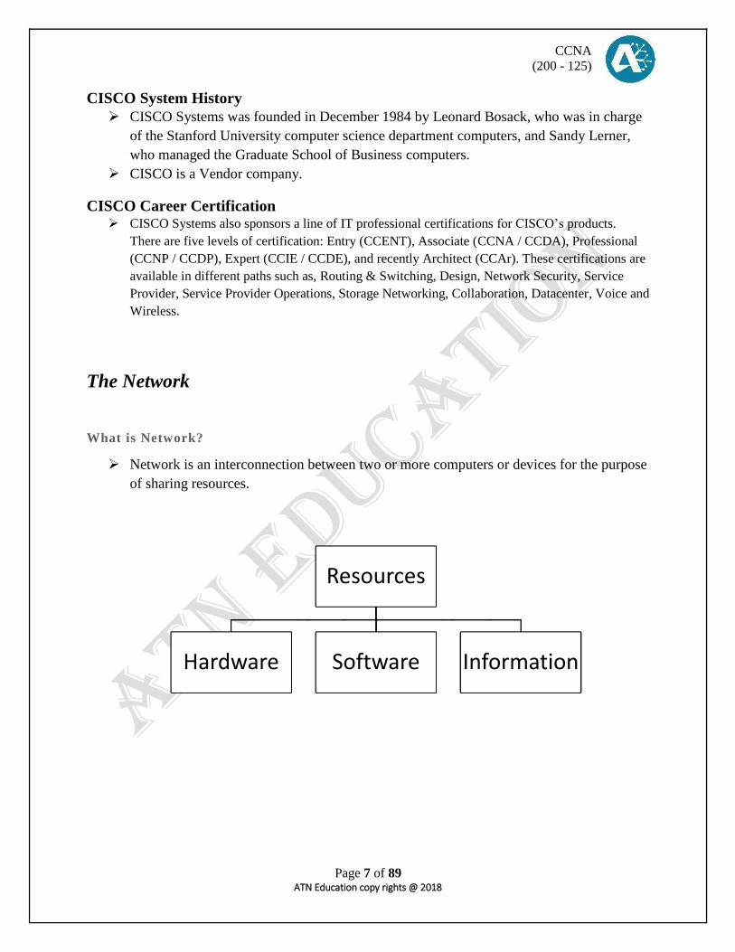
Network is an interconnection between two or more computers or devices for the purpose
of sharing resources.
Resources
Hardware Software Information
CCNA
(200 - 125)
Page 8 of 89 ATN Education copy rights @ 2018
Network Devices
Network Devices are the components that are used to interconnect multiple
computing devices to form a network, in order to share files or resources.
Repeater
o An electronic device that receives incoming electrical or wireless or optical signals that
are weak or lower in strength and retransmits it at a higher level or higher power. The
physical layer of the OSI model (Layer 1).
Hub
o It is a device which is used to connect multiple computers in order to create a single LAN
network. A hub has 4, 8, 12, 24, 48 ports. This is belongs to physical layer of the OSI
model (Layer 1).
Bridge
o It is a device which is used to connect to different computing device and also used to
divide a large network into small segments. This is belongs to Data Link layer of the OSI
reference model (Layer 2).
Switch
o A network switch generally contains more intelligence. Switches are capable of
inspecting data packets as they are received by determining the source and destination
devices of each packet, and forwarding them appropriately. By delivering messages only
to the connected device intended. Switch operates at the Data Link layer of the OSI
model (Layer 2).
Router
o Routers are used to connect two or more networks together. Routers have sophisticated
routing table which can determine the best route to get information from one network to
another. Routers are used to create separate broadcast domains. Routers belongs to the
Network Layer of the OSI model (Layer 3).

CCNA
(200 - 125)
Page 9 of 89 ATN Education copy rights @ 2018
Comparison between Hub, Switch and Router)
HUB
SWITCH
ROUTER
Single collision domain Each port has a collision domain Each port has a collision domain
Single broadcast domain Single broadcast domain Each port has a broadcast domain
Unmanageable Manageable and unmanageable Manageable and unmanageable
No security In – built security In – built security
Collision Domain
A collision domain is a set of interfaces for which a frame is sent by one interface could
result in a collision with a frame sent by any other interfaces in the same collision
domain.
Broadcast Domain
A broadcast domain is a set of interfaces for which a broadcast frame is sent by one
interface and it’s received by all other interfaces in the same broadcast domain.

CCNA
(200 - 125)
Page 10 of 89 ATN Education copy rights @ 2018
Types of Networks
LAN (Local Area Network)
LAN is a network which is implemented in a single geographical location.
WAN (Wide Area Network)
WAN is a network which is implemented among two or more geographical location.
MAN (Metropolitan Area Network)
A WAN implemented in a city by using fiber optic cables can be identified as MAN.
TAN (Tiny Area Network)
A LAN implemented by using maximum number of FIVE computers can be identified as
TAN.
CAN (Campus Area Network)
A WAN is implemented among universities or schools or military campus is called as
CAN.
SAN (Storage Area Network)
A WAN’s backup network
PAN (Personal Area Network)
Between home PC’s & Phones.
HAN (Home Area Network)
Networking between Home PC’s & other devices. (Intelligent Homes)

CCNA
(200 - 125)
Page 11 of 89 ATN Education copy rights @ 2018
Telecommunications methods
Duplex / Full Duplex
Communication in both directions simultaneously.
E.g. Telephone Calls
Half Duplex
Communication in both directions, but one direction at a time.
E.g. Walkie-Talkie
Simplex
Communication in one direction only.
E.g. a Radio Broadcast
Addressing method Unicast
Communication between a sender and a receiver.
Multicast
Communication between a sender and selected group of receivers.
Broadcast
Communication between a sender and all receivers in a network.

CCNA
(200 - 125)
Page 12 of 89 ATN Education copy rights @ 2018
Internet Protocol (IP) Addressing
Versions of IP address
I. IPv4
II. IPv6 (Brief CCNA)
IPv4
o An IP address (Internet Protocol) is a binary number that uniquely identifies computer and
other devices on a TCP/IP address can be private for use on a local area network (LAN)-
or public-for use on the internet or other wide area network (WAN).
o - IP addresses can be determined the statically-assigned to a computer by a system
administrator or dynamically assigned by DHCP (Dynamic Host Configuration Protocol).
o - Two IP addressing standards are in use today. The IPv4 standard is most familiar to
people and supported everywhere on the network, but the newer IPv6 standard is gradually
replacing it. IPv4 addresses consist of 4bytes (32bits), while IPv6 are 16bytes (128bits)
long.

CCNA
(200 - 125)
Page 13 of 89 ATN Education copy rights @ 2018
IP Types
Static IP
o Manually assign IP address in the TCP/IP Properties Page.
TCP: - Transmission Control Protocol
IP: - Internet Protocol
Dynamic IP
o Automatically assign IP address by the DHCP server or Operating System.
o Will be automatically changed.
APIPA
o Automatic Private IP Address.
o Which is given by the Operating System.
o Usually will be class B range.
o NID – 169.254 HID – 169.254.x.x
Example – 169.254.230.12
IP Ranges
Public Range
o Used in the internet / WAN connections for registered networks.
o Have to buy from an ISP.
Private Range
o Used in the intranet / LAN connections for unregistered networks.
o No need to buy from an ISP.
o Can be assign by the network admin or DHCP server.

CCNA
(200 - 125)
Page 14 of 89 ATN Education copy rights @ 2018
IP Scopes
Class A 1.0.0.0 - 126.255.255.255
10.0.0.0 - 10.255.255.255
Loopback / Stack testing
127.0.0.0 -- 127.255.255.255
Class B 128.0.0.0 - 191.255.255.255
172.16.0.0 - 172.31.255.255
Class C 192.0.0.0 - 223.255.255.255
192.168.0.0 - 192.168.255.255
*Class D : Reserved for Multicast
224.0.0.0 to 239.255.255.255
*Class E : Reserved for Experimental purpose
240.0.0.0 to 255.255.255.255
MAC Address (Media Access Control)
o This is a hardware address which is burned-in to the Network Interface Card. This
address cannot be changed. (MAC is a Physical address)
o First 24bits called as OUI; Last 24bits called as NIC
o OUI – Organizationally Unique Identifier
o NIC – Network Interface Controller
o Size – 48bits.
o Format - Hexadecimal.

CCNA
(200 - 125)
Page 15 of 89 ATN Education copy rights @ 2018
Subnetting We use subnetting to reduce IP wastages. Subnetting is all about taking the default mask of the IP and
extending it. (Extending – Increasing the network bits and decreasing the host bits.)
Classes Assignable IP address Class A 16, 777,214 (224 – 2)
Class B 65 ,534 (216 – 2)
Class C 254 (28 – 2)
On a WAN link,
Converting decimal into binary
128 + 64 + 32 + 16 + 8 + 4 + 2 + 1
192
168
1
1
192.168.1.0/24
192.168.1.1 192.168.1.2
*Wasted IP Address range: - 192.168.1.3 to 192.168.3.254
CCNA
(200 - 125)
Page 16 of 89 ATN Education copy rights @ 2018
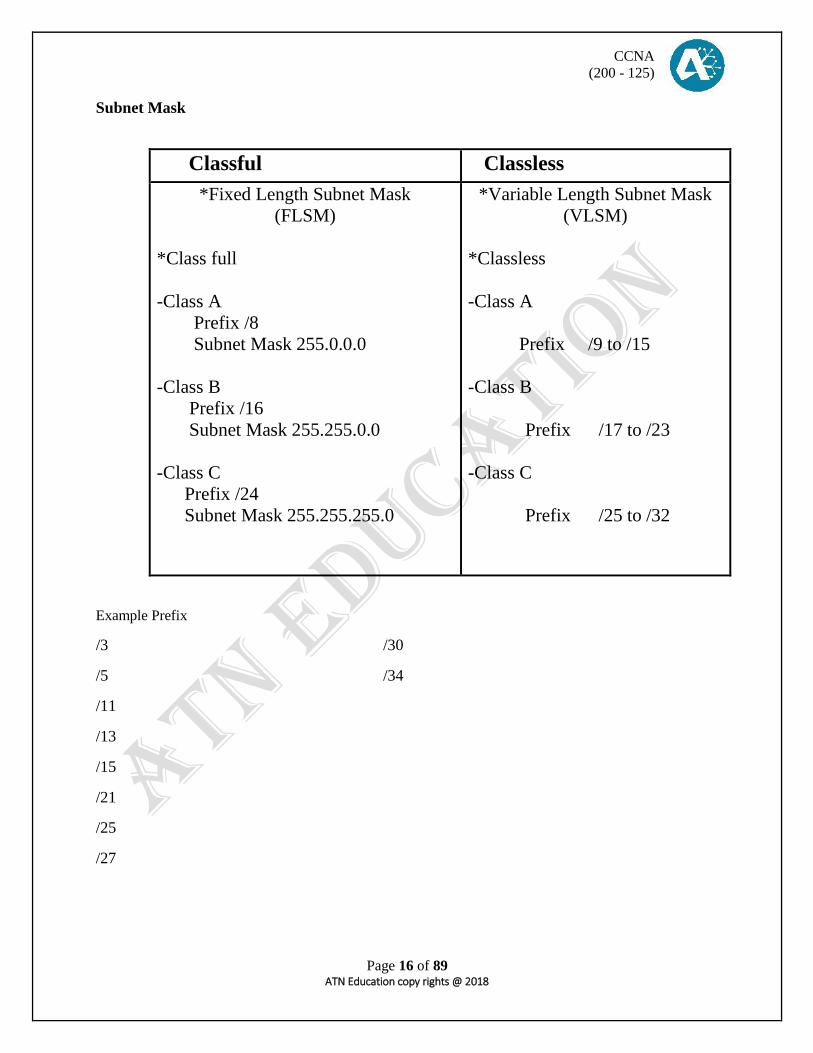
Subnet Mask
Classful Classless
*Fixed Length Subnet Mask
(FLSM)
*Class full
-Class A
Prefix /8
Subnet Mask 255.0.0.0
-Class B
Prefix /16
Subnet Mask 255.255.0.0
-Class C
Prefix /24
Subnet Mask 255.255.255.0
*Variable Length Subnet Mask
(VLSM)
*Classless
-Class A
Prefix /9 to /15
-Class B
Prefix /17 to /23
-Class C
Prefix /25 to /32
Example Prefix
/3 /30
/5 /34
/11
/13
/15
/21
/25
/27

CCNA
(200 - 125)
Page 17 of 89 ATN Education copy rights @ 2018
Variable length Subnet mask
Network bits cannot be changed but host bit can be changed.
Find subnet mask
o Add the network bits.
Find network address
o All host bits are “0”
Find first address
o All host bits are “0” except last one is “1”
Find last address
o All host bits are “1” except last one is “0”
Find broadcast address
o All host bits are “1”
Number of Host
o 2h – 2 (“h” - Host Bits)
Number of sub networks
o 2n (“n” - Network Bits)
*192.168.1.0 /24
128 + 64 + 32 + 16 + 8 + 4 + 2 + 1
1 1 0 0 0 0 0 0 Subnet mask :
Network address :
Frist address :
Last address :
Broadcast address :
No .of Host bits :
No .of network bits :

CCNA
(200 - 125)
Page 18 of 89 ATN Education copy rights @ 2018
Router Booting Process
Step 01 – The router performs a power-on-self-test (POST) to discover the hardware components and
verify that all components are working properly.
Step 02 – The router copies a bootstrap program from ROM into RAM and runs the bootstrap program.
Step 03 – The bootstrap program decides which IOS image to load into RAM loads that IOS. After
loading the IOS image, the bootstrap program hands over control of router hardware to newly loaded IOS.
Step 04 – After the bootstrap program loaded to IOS, Now IOS find the configuration file (Typically the
startup-config file in the NVRAM) and load it into RAM as the running-config.

CCNA
(200 - 125)
Page 19 of 89 ATN Education copy rights @ 2018
Basic Command-line Interface
Basic modes
User mode: hostname>
Privilege mode: hostname#
Global configuration mode: hostname(config)#
Basic configuration
Hostname configuration
Hostname (config) #Hostname (any name)
Banner configuration
Hostname (config) #banner motd $ welcome $
Router Configuration
G.M # Interface GigEthernet 0/0
#IP address 192.168.1.1 255.255.255.0
#No shutdown
Switch configuration
G.M #Interface VLAN 1
#IP address 192.168.1.2 255.255.255.0
#No shutdown
Hostname> enable
Hostname# configure terminal

CCNA
(200 - 125)
Page 20 of 89 ATN Education copy rights @ 2018
Troubleshooting and Show commands
Check the IOS version and the device information
Hostname #Show version
Check the Flash memory
Hostname #Show flash
Check the RAM (Example Output…)
Hostname #Show running-config
Check the NVRAM (Example Output…)
Hostname #Show startup-config
Check the Address Resolution Protocol (ARP) table
Hostname #Show IP ARP
Hostname #Show ARP
Check the Media Access Control (MAC) table (Switch)
Hostname #Show mac address-table
Hostname #Show mac address-table
Check the Routing table (Router) Hostname #Show IP ARP
Set the clock in Router Router #Clock set 11:00:00 01 Jan 2018

CCNA
(200 - 125)
Page 21 of 89 ATN Education copy rights @ 2018
Secure CISCO Router and Switch
Configure a line console password
Router (config) #Line console 0
Router (config-line) #Password cisco
Router (config-line) #login
Configuring enable password and enable secret
Enable Password: - Router (config) #Enable password cisco
Enable Secret: - Router (config) #Enable secret cisco123
Configure a terminal connection to the router
Router (config) #Line vty 0 4
Router (config-line) #Password cisco
Router (config-line) #login
Configure an auxiliary password
Router (config) #line aux 0
Router (config-line) #password cisco
Router (config-line) #login

CCNA
(200 - 125)
Page 22 of 89 ATN Education copy rights @ 2018
Cisco Discovery Protocol (CDP)
The Cisco Discovery Protocol is a proprietary Data Link Layer and Network Layer protocol developed by
Cisco Systems. It is used to share information about other directly connected Cisco equipment, such as
the operating system version and IP address. CDP can also be used for On-Demand Routing, which is a
method of including routing information in CDP announcements so that dynamic routing protocols do not
need to be used in simple networks.
o Global CDP information: Sending CDP packets every 60 seconds
Sending a hold time value of 180 seconds
CDP show commands
Hostname #Show CDP
Hostname #Show CDP neighbors
Hostname #show CDP entry *
Hostname #show CDP neighbors detail
Enable and disable CDP
Hostname (config) #CDP run
Hostname (config) #No CDP run
CDP timers and version
Hostname (config) #CDP timer 50
Hostname (config) #CDP hold time 120
Hostname (config) #CDP advertise-v2
C I S C O
C I S C O C I S C O

CCNA
(200 - 125)
Page 23 of 89 ATN Education copy rights @ 2018
Link Layer Discovery protocol (LLDP) /IEEE 802.1AB
o An industry Standard protocol that allows network devices supporting Link layer
discovery protocol (that are layer 2 adjacent) to dynamically discover one or other.
Trivially File Transfer Protocol (TFTP)
The Trivially File Transfer Protocol (TFTP) is an internet software utility for transferring files that is the
simpler to use than the file Transfer protocol (FTP) but less capable.it is use where user authentication
and directory visibility are not required. TFTP uses the user datagram protocol (UDP) rather than the
transmission control protocol (TCP) TFTP is described formally in request for comment (RFC) 1350.
TFTP Command
Save file from RAM to TFTP
Hostname #Copy running-config tftp:
Save file from NVRAM to TFTP
Hostname #Copy startup-config tftp:
Save file from FLASH to TFTP
Hostname #Copy flash: tftp:
Upload file from TFTP to RAM
Hostname #Copy tftp: running-config
Upload file from TFTP to NVRAM
Hostname #Copy tftp: startup-config
Upload file from TFTP to FLASH
Hostname #Copy tftp: flash:
Save file from RAM to NVRAM
Hostname #Copy running-config startup-config
C I S C O
NON-CISCO NON-CISCO

CCNA
(200 - 125)
Page 24 of 89 ATN Education copy rights @ 2018
Cabling
Transmission media
WIRED WIRELESS
*Coaxial -Thin
-Thick
*Twisted Pair -Shielded Twisted Pair
-Unshielded Twisted
pair
*Fiber Optic
-Single mode Fiber
-Multi mode Fiber
*Infrared
*Bluetooth
*Wi-Fi
*Wi-Max
Network Devices
MAC NON_MAC
*N I C
*Router
*Network Provider
*Hub
*Bridge
*Switch

CCNA
(200 - 125)
Page 25 of 89 ATN Education copy rights @ 2018
Network Technician Tool kits
Crimping Tool
Cable Tester
Punch down tool
RJ-45 Connectors
UTP-cable
STRIGHT THROGH CABLE
(mac to non-mac)
CROSSOVER CABLE
(mac-mac/non-mac-non-mac)
ROLLOVER CABLE
(console)
White orange - white orange
Orange - Orange
White green - White green
Blue - Blue
White Blue - white Blue
Green - Green
White Brown - white brown
Brown - Brown
White Orange - white Green
Orange - Green
White Green - White Orange
Blue - Blue
White Blue - White Blue
Green - Orange
White Brown - White Brown
Brown – Brown
White orange - Brown
Orange - White brown
White Green - Green
Blue - White Blue
White Blue - Blue
Green - White green
White Brown - Orange
Brown - White Orange
+++

CCNA
(200 - 125)
Page 26 of 89 ATN Education copy rights @ 2018
Network Reference model
*Open System Interconnection (OSI model)
-Theoretical model
-Has 7 Architectural layer
-Protocol independent standard
*Transmission Control Protocol / Internet Protocol (TCP / IP)
-Model around which internet is developed
-Has 4 Architectural layers
-Protocols depended standard
Application
Application Presentation
Session
Transport Transport
Network Network
Data link
Physical Network interface

CCNA
(200 - 125)
Page 27 of 89 ATN Education copy rights @ 2018
Open System Interconnecting -Developed by the International Organization for Standardization and introduced around 1980.
-It’s a layered architecture (consists of 7 layers) which defines and explains how the
communication happens in between 2 or more network devices within the organization or internet
each layer defines a set of functions in data communication.
Application
Presentation Software layer
Session
Transport
Network hardware layer
Data link
Physical
Protocol data unit (PDUs)
-The names given to data of different layer of the OSI model.
Transport - Segments
Network - Packets
Data link - Frames
Physical - Bits

CCNA
(200 - 125)
Page 28 of 89 ATN Education copy rights @ 2018
APPLICATION LAYER (Layer 7)
-Providing on interface for the users to interact with application services or networking
services. (Ex. Web server)
-Identification of services is done using port numbers port is a logical communication
channel port number is a 16 bits identifier.
Total no port = 0 - 65,535
Reserved port =1 - 1023
Unreserved port= 1024 - 65,535
Services Port Number
HTTP
FTP
SMTP
TELNET
TFTP
80
21
25
23
69
PRESENTATION LAYER (Layer 6)
-Responsible for defining a standard format for the data it deals with data presentation.
-Encoding: Decoding
Ex. ACSII, EBCDIC (text)
JPG, GIF, TIFF (Graphic)
MIDI, WAV (voice)
MPEG, DAT, AVI (video)
-Encryption: Decryption
Ex. DES, 3-DES, AES
-Compression: Decompression
Ex. Predictor, stacker, MPPC
SESSION LAYER (layer 5)
-It’s responsible for establishing, maintaining and terminating the session.
-It deals with session or interconnecting between the applications session ID is used to
identify a session or interaction. (Ex. RPC, SQC, NFS)
APPLICATION LAYER PROTOCOL inside
TCP / IP
Application
Presentation Application
Session

CCNA
(200 - 125)
Page 29 of 89 ATN Education copy rights @ 2018
Application Layer
Provides and Interface between software running on a computer and the network itself. Example
for this layer.
HTTP : Hypertext Transfer protocol
TELNET : Telecommunication Transfer Protocol
FTP : File Transfer Protocol
TFTP : Trivial file Transfer Protocol
SMTP : Simple Mail Transfer Protocol
SNMP : Simple Network Management protocol
DHCP : Dynamic Host Configuration Protocol
DNS : Domain Name System
HTTP : Allows to access webpage
: http://www.google.com
FTP : It allows you to transfer files from one machine to another.
: It also allows access to both directories and files.
: It uses TCP for data transfer and ends slow but reliable.
TELNET : Telnet is use for terminal immolation. Its allows user sitting on a remote
machine
To access the resource of another machine.
SMTP : Allows you to send and receive emails messages.
TFTP : This is stripped down version of FTP.
: It has no directory browsing abilities.
: It can only send & receive.
: It uses UDP for data transfer & hence faster but not reliable.
SNMP : enable a center management of network. Its works with TCP/IP.
: using SNMP an administrator can watch the entire network.
: It uses UDP for transportation of the data.
DHCP : Dynamically assigns IP address to hosts.
: Also provide DNs and Gateway information if needed.
DNS : DNS resolves FQDN with IP address.
: DNS allows you to use a domain name to specify & IP address.
: It maintains a database for IP address and hostnames.

CCNA
(200 - 125)
Page 30 of 89 ATN Education copy rights @ 2018
TRANSPORT LAYER (Layer 4)
-Responsible for End-to-end transportation of data between the application.
-The major functions describe at the transport layer are……
01. Identifying Service
02. Multiplexing and De-multiplexing
03. Segmentation
04. Sequencing and Reassembling
05. Error connection
06. Flow control
(01) Identifying Service
o Services are identified at this layer with the help of port numbers.
o The major protocols which takes care of data transportation at transport layers are………
T C P
U D P
T C P U D P
* Transmission Control Protocol
* Connection oriented
* Reliable communication (with ACK’S)
* Slower data Transportation
* Protocol number is 6
Ex. HTTP, FTP, SMTP
* User Datagram protocol
* Connection less
* Unreliable communication (no ACK’S)
* Faster data transportation
* Protocol number is 17
Ex. DNS, DHCP, TFTP
(02). Multiplexing and De-multiplexing

CCNA
(200 - 125)
Page 31 of 89 ATN Education copy rights @ 2018
(03). Flow control
NETWORK LAYER (layer 3)
- Its responsible for end-to-end transportation of data across multiple networks.
- Logical addressing and path determination (routing) are described at this layer.
- The protocols work at network layers are…….
Routed protocols and Routing Protocols.
Routed Protocols
- Routed protocols acts as data carries and defines logical addressing.
Ex. IP, IPX, APPLE Talk…etc.
Routing Protocols
-Routing protocols perform path determination (routing).
-Devices work at network layer are router, Multilayer switch.
Ex. RIP, EIGRP, OSPF, BGP...etc.
DATA LINK LAYER (layer 2)
-Its responsible for end-to-end delivery of data between the devices on a LAN network
segment.
-Data link layer comprises of two sub layers.
-It deals with hardware addresses (MAC address)
-It also provides ERROR DETECATION using CRC (Cycle Redundancy Check) and
FRAMING (Encapsulation).
-Derives works at data link layer are switches

CCNA
(200 - 125)
Page 32 of 89 ATN Education copy rights @ 2018
PHYSICAL LAYER (layer 1)
-It deals with physical transmission of binary data on the gives media. (Ex. copper, Fiber,
wireless)
-It also deals with electrical, mechanical and functional specification of the devices
media.
COPPER : Electrical signals of different voltages.
FIBER : Light pluses of different wave length.
WIRELESS : Radio frequency waves.
.
Application (Data) Application
Presentation (Data) Presentation
Session (Data) Session
Transport (Segment) Transport
Network (Packet) Network
Data Link (Frame) Data Link
Physical (Bits) Physical
L/ H S / H Data IP / H L/ H L/ H S / H Data IP / H L/ H

CCNA
(200 - 125)
Page 33 of 89 ATN Education copy rights @ 2018
Switching Address Learning
Forward and Filtering
Loop Avoidance
Address Learning
-Layer 2 switches and bridges remember the source MAC address of each frame
received on an interface, and enter this information into a MAC-table called a
forward and filter table.
Forward and Filtering
-When a frame is received on an interface, the switches looks at the destination
MAC address and finds the exit interface in the MAC-table the frame is only
forwarded out this specified destination port.
Port
Port
MAC address
MAC address
Fa 0/1 AAAA
Fa 0/2 BBBB
Fa 0/3 DDDD
EEEE
Fa 0/4 CCCC
Fa 0/1 AAAA
BBBB
CCCC
Fa 0/2 DDDD
Fa 0/3 EEEE
SW1
SW2

CCNA
(200 - 125)
Page 34 of 89 ATN Education copy rights @ 2018
Address Resolution Protocol (ARP)
-To communicate between 2 host, we need a MAC address if you wish to send data through
10.1.1.3 the ARP will drop the MAC address of the devices which are connected and it will have
updated it to database from the destination MAC will be figure out the data will be send.
Source IP
10.1.1.1
Destination IP
10.1.1.3
Source MAC
AAAA
Destination
MAC
?
Data
(…………)
Loop Avoidance
-If multiple connection between switches are created for redundancy purposes, network loops can
occur, spanning-tree protocol (STP) is used to stop network loops while still permitting
redundancy.
Bridging Loops
*Redundant link between switches provide redundancy also possibility to
create loops when switches do broadcast
*Broadcast storm
*MAC table instability
*multiple frame transmission
*Bridging loops
Bridging loops solution?
SPANNING-TREE
PROTOCOL

CCNA
(200 - 125)
Page 35 of 89 ATN Education copy rights @ 2018
Spanning-Tree Protocol (STP) -STP stops the loop which occurs when you have multiple links between switches.
-STP avoids broadcast storms, multiple frame copies for database and MAC-table
instability.
-STP is open standard protocol (IEEE 802.1D)
-STP is enable by default on all cisco switches.
How to STP works?
- Selecting the root bridge
* The bridge with the best bridge ID (lowest)
* Bridge ID= priority, MAC address of the switch.
* Out of all the switches in the network one is selected.
- As a root bridge that becomes the circle point in the network
- Every LAN will have only one root bridge for all remain switches will be considering as
non-root bridges.
Selecting the root port
- Shortest path to the root bridge
- Every non-root bridge looks the best way to go to root bridge
- Least cost (speed)
- The lowest forwarding switch ID (priority + MAC))
- Lowest forwarding physical port number.
- Every non-root bridge there is only one root port.
STP port cost
Link speed / Load
width
Port cost
10 MBPS
100 MBPS
1 GBPS
10 GBPS
100
19
4
2
Selecting designated port
-Least cost
-Least local switch ID
-Lowest local physical port number
-One designated port is selected per segment

CCNA
(200 - 125)
Page 36 of 89 ATN Education copy rights @ 2018
Selecting block port
-All non-root and non-designated port are block port.
Bridge Protocol Data Unit (BPDU)
- All switches exchange information through what is called as bridge protocol data unit
- Hello = BPDUs are sent every 2 seconds
- Max age (Dead) = 20 seconds
- Forward delay (listing +learning time= 15 second)
- A BPDUs contains information regarding ports switches port priority and address.
STP port stages
- Blocking 20 seconds / no limits
- Listening 15 se
- Learning 15 sec
- Forwarding no limits
- Disable no limits
Verifying spanning-tree
PM #Show spanning-tree
P.M #Show spanning-tree vlan (VLAN ID)
PM #Show spanning-tree root

CCNA
(200 - 125)
Page 37 of 89 ATN Education copy rights @ 2018
Spanning-tree port fast
- Cisco – proprietary enhancement to spanning-tree
- Helps speed up network convergence on access ports
- Port causes port to enter the spanning tree forwarding state immediately, by passing (skipping)
the listening and learning states.
NOTE : Port fast should be used only when connecting a single end station to a switch port.
: If you enable port fast on a port connected to another networking devices, such as a switch, it
can create network loops.
PORT FAST CONGIGURATION
Port by port
GM #Interface range …….. ……….
#Spanning-tree port fast
Globally
GM #Spanning-tree port fast default
Uplink fast
- Uplink fast is for speeding convergence when a direct link failure on an uplink switch
face.
- When uplink fast is enable it is enable for the entire switch.
Listening : 15 sec
Learning : 15 sec
Forwarding : 20 sec
1 sec
GM #Spanning-tree uplink fast
*This command is not allowed on root bridge switch when uplink fast is configure the bridge
priority is changed to 49152. So that this switch will not root be selected as a root.

CCNA
(200 - 125)
Page 38 of 89 ATN Education copy rights @ 2018
Backbone fast -Backbone fast can reduce the maximum convergence delay only from 15 to 30 second.
GM #Spanning-tree backbone fast
PM #Show spanning-tree
BPDU GUARD
- BPDU guard prevents loops if another switch is attached to a port fast (access) port.
- When BPDU guard is enable on an interface it is put into an error disable state (basically
shutdown) if a BPDU received on that interface.
- It can be enable at ether config mode effects all (Port fast interface) or at interface mode.
- Port fast does not need to be enable for it to be configure at a specific interface.
GM #Spanning-tree portfast bpdu guard default
PM #Spanning-tree bpdu guard enable
BPDU filter
GM #Spanning-tree portfast bpdu filter default
- If a port fast interface received any BPDUs it is taken out of port fast status.
- The interface still sends some BPDU at the link up.
- If a BPDU is received the interface losses its port fast status
- BPDU filtering is disable
*IM #Spanning-tree bpdu filter enable
- The interface doesn’t send any BPDU + ignores the received one.
- The port is not shutdown this basically disable STP on the interface.

CCNA
(200 - 125)
Page 39 of 89 ATN Education copy rights @ 2018
RSTP * IEEE 802.1W is a standard way of speeding STP convergence.
* Inbuilt features of port fast, uplink fast, backbone fast path calculation remains same as STP.
RSTP port states
Comparison between 802.1D & 802.1W
STP port steps RSTP port steps
Disable
Blocking
Listing
Learning
Forwarding
Discarding
Discarding
Discarding
learning
forwarding
Discarding : frames are dropped, no addresses are learned (link down/blocking/during sync)
Learning : frames are dropped, but addresses are learned
Forwarding : frame is forwarded.
RSTP port roles
1. Root port
- The best path to root (same as STP)
2. Designation port
- Same role as with STP
3. Alternate port
- A backup to the root path.
- Less desirable path to the root.
- Operates in discarding state
- Same as uplink fast (legacy).
4. Backup port
- A backup to the designated port
- The backup port applies only when a single switch has to links to the segment
(collision domain).
- To have two links to the same collision domain, the switch must be attached to
a hub.
- Multiple links attached to the network segment.
- Actives if primary designated frames.
5. disable port
- Not used in the spanning-tree.
6. Edge port
- Connected only to an end user.
- Equivalent to port fast in STP.
- Maintain edge status as long as no BPDU received (with BPDU filter).

CCNA
(200 - 125)
Page 40 of 89 ATN Education copy rights @ 2018
BPDU different in STP
- In regular STP, BPDU are originated by the root and relayed by each switch.
- In RSTP, each switch originates BPDUs, Whether or not it receives a BPDU on its root port.
- Previously is done by Rapid previously on catalyst switches Hello =2 sec, dead = 6 sec.
RSTP configure
GM` #Spanning-0tree mode Rapid-PVST
VLAN - Divides a single broadcast into multiple broadcast domain.
- A layer 2 security.
- VLAN 1 is the default.
- VLAN can be created from 2 – 1002.
- Can be configured on a manageable switch only.
Benefits for VLAN
- Limit the number of broadcast.
- Better performance.
- Security.
Point-to-Point

CCNA
(200 - 125)
Page 41 of 89 ATN Education copy rights @ 2018
TYPES of VLANs
- Static VLAN.
- Dynamically VLAN.
Static VLAN
- Static VLANs are based on port number.
- Need to manually assign a port on a switch through a VLAN.
- One port can be a member of only one VLAN.
VLAN config
GM #vlan ………………………
#Name …………………….
Assign port to vlan
GM #Interface ….. ………….
#Switchport mode access
#Switchport access vlan ………..
GM #Interface range ……….. ……….
#Switchport mode access
#Switchport access vlan ………….
Dynamic VLAN
- Dynamically VLANs are based on the MAC address of a pc.
- Switch automatically assign the port to a VLAN.
- Each port can be a member of multiple VLANs.
- For dynamic VLAN configuration, a software called VMPS. (VLAN member policy server) is
needed.

CCNA
(200 - 125)
Page 42 of 89 ATN Education copy rights @ 2018
TRUNKING - A single VLAN can span over multiple switches.
Types of links / ports
Access link
- Connecting to end devices.
- Port of one VLAN.
Trunk links
- Does not belong to any VLAN.
- Carries multiple VLAN traffic.
- Link between 2 switches.
Frame Tagging
- In order to make sure that same VLAN users on different switches communicate with each other
there is a method of tagging happens on trunk links.
- Tag is added before a frame is send and removed once it is received on trunk link.
- Frame tagging happens only on the trunk links.
Trunking protocols
I S L (Inter Switch Link) IEEE 802.1Q
- It’s a cisco proprietary.
- It adds 30 bytes of tag.
- Maximum 1000 VLANs.
- Open standard.
- Only 4-byte tag will be added to original frame.
- Maximum 4096 VLANs.
Trunk configuration
*Switch 2950 & below (option 1) *Switch 3550-above (option 2)
G.M #Interface Fastethernet 0/0 G.M #Interface fastethernet 0/0
#switchport mode trunk #Switchport trunk encapsulation dot1q
#Switchport mode trunk
VLAN = Broadcast Domain = Subnet

CCNA
(200 - 125)
Page 43 of 89 ATN Education copy rights @ 2018
INTER-VLAN Routing
- Packets in one VLAN cannot across another VLAN.
- To transfer packets between vlan you must use layer 3 devices.
- Router must have a physical or logical connection to each VLAN so that it can forward packets
Between them.
- Inter-VLAN routing can be performed by on external router that connects to each of the VLANs
on switch.
Inter-vlan methods
- Ligancy method (spate physical gateway on a router).
- Router on a stick.
- Using multilayer switch (layer 3).
Inter-VLAN routing using a router (router on a stick)
Router configuration
G.M #Interface fastethernet 0/0
#No shutdown
G.M #Interface fastethernet 0/0
#Encapsulation dot1q (vlan ID)
#IP address 192.168.1.1 255.255.255.0

CCNA
(200 - 125)
Page 44 of 89 ATN Education copy rights @ 2018
Inter VLAN Routing with MLS (Multilayer- switch)
G.M #IP routing
Extended vlan
- Cisco refers to be vlan between 1025 – 4096 on extended range vlan.
- Cisco catalyst switches support extended range VLANs under the following, VTP cannot be
used for vlan management (VTP must be configured in transparent mode or it will be off)
Voice vlan
-a vlan that be configured on a cisco catalyst switch for the purpose of carrying voice packets to
End from IP phones.
G.M #Interface fastethernet 0/0
#Switchport voice vlan (vlan ID)
Default vlan configuration
- The voice vlan feature is disabled by default.
- You should configure voice vlan on switch access port.
- The voice vlan should be present and be active on the switch for the IP phone to connect the
communication on the voice vlan.
-The port fast feature is automatically enabled when voice vlan is configured.
- Use PM #Show vlan command to see whether the vlan is present.

CCNA
(200 - 125)
Page 45 of 89 ATN Education copy rights @ 2018
Native vlan
- If a packet is received on a dot1q link that doesn’t have vlan tag it is assured that it belongs to
native vlan.
- Default NATIVE vlan s is VLANs.
G.M #Interface fastethernet 0/0
#Switchport mode trunk
#Switchport trunk native vlan (vlan ID)
Native vlan best properties
- Best practice to configure the native vlan ID to vlan 666 to 999 and to ensure that this vlan is
not used anywhere in the network.
- No ports should be assigned to the native vlan.
- And attack a who attacks to use the vlan. Hopping attack will end up in a dead vlan that has no
cost to leverage.
VTP (Virtual Trunking Protocol)
- VTP is a cisco propriety protocol used to share configure with multiple switches to maintain
consistency to out that network.
- VTP manage the addition, dedication and remaining of vlans across the network from a center
point of control.
- Information will be pass only if switches connected with fastethernet or higher ports.
- Also, must be trunk link.
- Switches should be configured with same domain.

CCNA
(200 - 125)
Page 46 of 89 ATN Education copy rights @ 2018
VTP Trunking protocol
VTP requirement to transfer data
- Same VTP domain
- Trunk links
- Password
VTP mode Description
1. SERVER
2. CLIENT
3. TRANSPERENT
* Can be used to create, modify and delete vlans
file.
* Updates its vlan data base based on received
advertisement.
* Forward received VTP massage.
* Can originate advertisement
* Can’t be used to create modify and delete vlans
file.
* Updates its vlan data base based on received
advertisement.
* Forward received VTP massage.
* Can originate VTP advertisement
* Can be used to create modify and delete vlans
file.
* Doesn’t updates its vlan data base based on
received advertisement.
* Forward received VTP massage.
* Doesn’t originate VTP advertisement
Configuration revision number
-VTP advertise via VTP including a version after switches vlan database, which gets increment
by one for any changes mode to the vlan database.
VTP configuration
GM #vtp mode (server/transparent/client)
GM #vtp domain ccna
GM #vtp password CISCO123
GM #vtp version 2
Show commands
PM #Show vtp status
PM #Show vtp password

CCNA
(200 - 125)
Page 47 of 89 ATN Education copy rights @ 2018
Ether channel - Used to aggregate bandwidth between multiple L2 & L3 interfaces.
- Ether channel increases bandwidth for provides redundancy by aggregating individual links
between switches.
- Ether channel load balance traffic over all the links in the bundling.
- Up to 8 links can be used to combine into one logical link.
- Ether chancel can be configured as layer 2 or layer 3.
- Port channel is the logical instance of the physical interfaces.
Ether channel mode
- Ether channel can be dynamically configured between switches using two protocols.
*PAgP (port aggregation protocol) – cisco propriety
*LACP (link aggregation control protocol) –open standard
Guidelines for Ether channel configuration
- Interfaces in the channel do not have to be physically next to each other or on the same module.
- All ports must be on same speed for duplex.
- All port in the bundle should be enabled.
- None of the bundle ports can be a spam port.
- Assign an IP address to the logical port channel interface not the physical ones. (if using a
layer3 ether channel).
- Put all bundle ports in the same vlan or make them all trunks.
- If they are trunks they must all carry he same vlans and use the same Trunking mode.
- The configuration you apply to the port channel interface a effects the entire Ether channel.
-the configuration you apply to a physical interface effects only that interface.
PAgP port Negotiation
PAgP ON AUTO DESIRABLE
ON √ × ×
AUTO × × √
DESIRABLE × √ √
LACP port Negotiation
LACP ON PASSIVE ACTIVE
ON √ × ×
PASSIVE × × √

CCNA
(200 - 125)
Page 48 of 89 ATN Education copy rights @ 2018
ACTIVE × √ √
Ether channel configuration
GM #Interface range fastethernet 0/11-12
#Channel-group (group-no) mode (on/auto/desirable/passive/active)
Verification
PM #Show etherchannel
PORT SECURITY - It means blocking unknown person login to the switch by default the MAC address will be
dynamically appear on your database which can stop by on your port-security.
- There 3 violations are,
1. Shutdown : It put the port into error –disable state.
2. Restrict : Ignores all the traffic interface and count the violation.
3. Protect : Ignores all the traffic interface and doesn’t count the violation.
Port-security configuration
GM #Interface fastethernet 0/0
#Switchport mode access
#Switchport port-security
#Switchport port-security maximum (number)
#Switchport port-security mac-address _ _ _ _ _ _ _ _ _ _
#Switchport port-security violation (restrict/protect/shutdown)
P.M #Show port-security
Fa 0/11
Fa 0/12
Fa 0/11
Fa 0/12
Switch MAC-address use sticky

CCNA
(200 - 125)
Page 49 of 89 ATN Education copy rights @ 2018
Routing -Forwarding of packets from one network to another network.
Routing
IGP EGP
Static default dynamically
-MANNUAL -R I P
-NET.ADMIN -IGRP
-MOST SECURE -OSPF
-DELAY to CONFIG -IS – IS
-RISKY -EIGRP
IGP : Interior Gateway Protocol
EGP : Exterior Gateway Protocol
BGP : Border Gateway Protocol
RIP : Routing Information Protocol
IGRP : Interior Gateway Routing Protocol
OSPF : Open shortest path First
IS-IS : Intermediate system Intermediate system
EIGRP : Enhanced Interior Gateway Routing Protocol
Dynamic
Classful Classless
-R I P -R I P V2
-I G R P -EIGRP
-IS – IS
-OSPF

CCNA
(200 - 125)
Page 50 of 89 ATN Education copy rights @ 2018
Interior Gateway Protocol (IGB)
- It’s used to exchange routing information with routers in the same autonomous system.
Exterior Gateway Protocol (EGP)
- Its used to communicate between different autonomous systems.
Administrative distance
Router Source Administrative Distance
Directly connected
Static
EIGRP
IGRP
OSPF
IS-IS
RIP
External EIGRP
Internal BGP
Unknown
0
1
90
100
110
115
120
170
200
25

CCNA
(200 - 125)
Page 51 of 89 ATN Education copy rights @ 2018
Static route
Advantages are
IP configure by administrative.
It is secured and fast.
No band with usage.
No much CPU process.
Disadvantages are
Administrative has to understand the whole network before implementing.
If one route is down in a network.
If can’t be implemented to a usage network.
The administrative has to reconfigure all the router in the network.
GM #Interface serial 0/0/0
#IP address 10.1.1.1 255.255.255.0
#Clock rate 64000 (only DCE port)
#Bandwidth 64
#No shutdown
GM #IP default-gateway (router-IP)
Static Configuration
GM #IP route (designated network) (subnet mask) (next hop IP)
PM #Show controller serial 0/0/0

CCNA
(200 - 125)
Page 52 of 89 ATN Education copy rights @ 2018
Default route
A default routing protocol its configure for unknown destination
GM #IP route (destination network) (subnet mask) (next hop IP)
Dynamic routing protocol
Advantages of dynamic over static.
Works with advertisement of directly connected network.
No need to know the destination.
Update the tropology changes dynamically.
Administrative work is reduced.
Used for large organization.
Neighbor router exchange routing information and build the routing table automatically.
Distance vector Link state vector Hybrid vector
Works with Bellman
ford's algorithm.
Periodic update.
Full routing tables are
exchange.
Full class routing
protocol.
Update are through
broadcast.
Less overhead.
Easy to configure.
Works with Dijkstra’s
algorithm.
Link state update and
incremented update.
Missing router are
exchange.
Class less routing
protocol.
Updates are through multi
caste.
More overhead.
Difficult to configure.
Works with Dual
algorithm.
Incremented
update.
Missing router are
exchange.
Class less routing
protocol.
Updates are
through multi
caste.
Less overhead.
Easy to configure.

CCNA
(200 - 125)
Page 53 of 89 ATN Education copy rights @ 2018
RIP (Routing Information Protocol)
Advantages of RIP
Used for small organization.
Exchange interior routing table for every 30 seconds.
No authentication.
Supports authentication.
Disadvantages of RIP
Bandwidth utilization is very high has broadcast for every 30 seconds.
Works only on hop count not considering bandwidth.
Not scalable on hop count is only 15.
Slow convergence.
GM #Router rip
#Network _ _ _ _ _ _ _ _
#Version 2
RIP V1 RIP V2
Open standard.
Class full routing protocol.
Updates are broadcast via
255.255.255.255
Metric hop count.
Maximum hop count 15.
Open standard.
Class less routing protocol.
Uses multi caste address of 224.0.0.9
Metric hop count.
Maximum hop count 15.

CCNA
(200 - 125)
Page 54 of 89 ATN Education copy rights @ 2018

CCNA
(200 - 125)
Page 55 of 89 ATN Education copy rights @ 2018
EIGRP (Enhanced Interior Gateway Routing Protocol) Advance distance vector. (Hybrid Protocol)
Standard protocol.
Class less routing protocol.
Include all features of IGRP.
Maximum hop count is 255. (Default by 100)
Administrative distance is 90.
Flexible network design.
Multi caste and unique caste instant of broadcast address.
100% Loop free class less routing.
Easy configuration for the LANs and WANs.
EIGRP table
1. Neighbor table
Contains distance directly connected neighbors.
2. Topology table
List of all the best routs learn from each neighbor.
3. Routing table
The best route for destination.
Update are through multicast 224.0.0.10
Hello packets are send every 5 seconds.
Convergence rate is fast.
Supports IP, IPX and apple talk protocol.
Supports equal cost and un equal cost load balancing.
It was dual (Diffusing update algorithm).
A B
224.0.0.10 (hello)
ACK 224.0.0.10 (Hello)
Updates
Updates
Best port
Best port

CCNA
(200 - 125)
Page 56 of 89 ATN Education copy rights @ 2018
EIGRB metric EIGRB packets 1. Bandwidth - Allows (every 5 seconds, Dead in 15 seconds)
2. Delay - Updates quarries replay acknowledgement.
3. Load
4. Maximum transmission units
5. Reliability
K values
K1 : 1
K2 : 0
K3 : 1
K4 : 0
K5 : 0
Dual (diffusing update algorithm)
Total cost from local router to destination
Cost from local router to AD of net hop router plus cost between the local router and the
next hop router
Flexible distance
A calculation made by EIGRB to determine the best loop minimize free port to network
Advertise distance
Cost from the next hop router to the destination
EIGRB also free calculate the second-best route is stratified the flexibility
Successor a route : The primary route to a network based on the having the lowest flexible distance
of all route in the EIGRP topology table.
Feasible successor a route : A backup a route to a network based on the route having the second
lowest feasible distance in the EIGRP topology table
*the feasible condition must be met.
Neighbor AD FD
R2 100 1100
R3 100 600

CCNA
(200 - 125)
Page 57 of 89 ATN Education copy rights @ 2018
Feasible condition : Before a route can become a feasible successor a route its advertised distance
has to be lower than the disable distance of the successor route.
GM #Router eigrp (autonomous no)
#Network _ _ _ _ _ _ _
#No auto-summary
OSPF (Open Shortest Path First)
Its open standard protocol.
It’s a link state protocol.
It was Dijkstra’s algorithm.
It has hop count unlimited
Metric calculation cost.
Administrative distance is 110.
It’s a classless routing protocol.
Its supports VLANs and CIDR.
Its support only equal cost load balancing.
Introducing concept area to fast management and the control traffic.
Updates are sends true multicast address.
Fast convergence.
Send “hello” packets every 10 sec.
Dead time equals “hello” into 4.
Incremental updates.
Neighbors process adjacency
- Neighbors are routers that, address on the same network links exchange hello massages.
- Adjacency are routers that, are neighbors have exchange link state update(LSUs) and data description (DD)
Hello
224.0.0.5
Hello
224.0.0.5
DD
DD
LSUs
LSUs

CCNA
(200 - 125)
Page 58 of 89 ATN Education copy rights @ 2018
I'm 30.0.0.1 and I see no one
I'm 30.0.0.2 and I see 10.0.0.1
I'll start exchange became I have router ID 1.1.1.1
I'll start exchange became I have highest router ID 2.2.2.2
Summary D B D
Summary D B D
Thanks for Information
I need the complete entry for 40.0.0.0, 50.0.0.0
Here is entry for 40.0.0.0, 50.0.0.0
I need the complete entry for 10.0.0.0, 20.0.0.0
Here is entry for 10.0.0.0, 20.0.0.0
Thanks for Information
Router ID.
- It’s the name of the router can configure manually using router ID command.
- The highest IP address of the active physical interface of the routers router ID.
- If logical interface configures the highest ip address of the logical interface is router ID
OSPF process.
- To become a neighbor hello, are, subnet mask and authentication should be match.
OSPF table
1. Neighbor table
- It also known as adjacency table.
- Conations list of directly connected router (neighbors).
2. Database table
- Typically refer to as LSDB (link state database).
2 way
state
Exterad state
Exchange
state
loading
state
state
Hello
Hell
o D D
D D
LS
Ack
LS
Ack LS
Request LS
Request
LS
Update
LS
Request
LS
Ack

CCNA
(200 - 125)
Page 59 of 89 ATN Education copy rights @ 2018
- Contains information about all the possible router to the networks with the area.
3. Routing table
- Contain list of best ports of each destination.

CCNA
(200 - 125)
Page 60 of 89 ATN Education copy rights @ 2018
OSPF AREA
- All the routers maintain same database
- Any changes import all the routers
- Area is logical grouping of router
- Minimize the size of database
- Restrict any changes within that areas (not flood outside areas)
- Routers within the same area participation in algorithms.
- OSPF avoids Hierarchical networks deigns with multiple different areas.
RULES
- Must have one area called as area “zero-0” (its backbone area)
- All the area must connect to area zer0
- At least one area border router should be there.
- Interface of the both routers facing must be in the same area.
Advantage of OSPF
- Open standard
- No hop count limitation
- Loop free
- Fast convergence
Disadvantages of OSPF
- Complex designs
- Consumes more CPU discovers
- Supports only equal cost balancing
- Support only IP protocol does not work on IPvX and Appletalk.
Single Area OSPF

CCNA
(200 - 125)
Page 61 of 89 ATN Education copy rights @ 2018
OSPF in Broadcast system
Designation router and backup router designation election (DR-BDR)
- Highest router ID
- Highest router priority (default 1)
OSPF packets types
- Hello
- Database description =DD
- Link state request =LSR
- Link state updates =LSU
- Link state acknowledgement=LS Ack
LSA Packets types
1. LSA type one : Router LSA (directly connected router)
2. LSA type two : Network LSA (DE & BDR process)
3. LSA type three : Summary LSA (ABR summary router)
4. LSA type four : Summary ASBR LSA
5. LSA type five : Autonomous System External LSA
6. LSA type six : Multicast OSPF LSA (not support & not used)
7. LSA type seven : Not saw stubby area LSA
8. LAS type eight : External Attribute LSA for BGP
Backup
update
10.0.0.0 update

CCNA
(200 - 125)
Page 62 of 89 ATN Education copy rights @ 2018
GM #Router ospf (autonomous no)
#Network (network address) (wildcard mask) area (area no)
ACCESS CONTROL LIST - ACL is a set of rules which will allowed or deny is specific traffic moving through the router.
- It is layer 3 security which control the flow of the traffic from one router to another
- It’s also called as packet filtering firewall.
Types of ACL
Number Named
Standard Extended Standard Extended
STANDARD ACL EXTENDARD ACL
*The access-list number range is 1-99
*Can block a network, host and subnet
*All services are block
*Implemented close to the destination
*Filtering is done based on only sources IP
addresses
* The access-list number range is 100-199
*Can allowed or deny a network, host and services
*Selected services can be block implemented
closes to the source
*Filtering is done based on source IP, destination
IP, and protocol and port number.
How to get wildcard mask?
255.255.255.255
255.255.255.0
0. 0. 0. 255

CCNA
(200 - 125)
Page 63 of 89 ATN Education copy rights @ 2018
ACL RULES
- Works in sequential order.
- All deny statement should be given first.
- There should be at least on permit statement.
- Can have one access list per interface per direction.
- To access list per interface one in “inbound” direction and one in “outbound” direction.
- Any time a new earlier added to the access list. If will be replace of the bottom of the list (using
a text editor for access list is highly suggested)
- You can’t remove one line from on access list
NAT & PAT
NAT (Network Address Translation)
- NAT is the method of translation of private IP address into public IP address.
- In order to communicate with interface, we must have registered public IP address.
Address translation was originality develop to solve to problems
*To handle a shortage of IPv4 address
*High network address in secure
Private IP range
Class A : 10.0.0.0 – 10.255.255.255
Class B : 172.16.0.0 – 172.31.255.255
Class C : 192.168.0.0 – 192.168.255.255
Types of NAT
* Static NAT
* Dynamic NAT
* PAT – NAT

CCNA
(200 - 125)
Page 64 of 89 ATN Education copy rights @ 2018
Static NAT
- One to one mapping done manually.
- For every private IP needs on register IP address.
Static (ISP) GM #IP route (public network) (subnet mask) (next hop IP)
Default (R1) GM #IP route (any network) (any subnet) (next hop IP)
G.M #IP nat inside source static (private range) (public range)
R1 configuration
G.M #Interface fastethernet 0/0
#IP nat inside
GM #Interface serial 0/0/0
#IP nat outside

CCNA
(200 - 125)
Page 65 of 89 ATN Education copy rights @ 2018
PAT (Port address Translation)
GM #Access-list (ACL no) permit (network address) (wildcard mask)
GM #IP nat pool (name) (start IP) (end IP) netmask (subnet mask)
GM #IP nat source list (ACL no) pool (pool name) overload
R1 configuration
GM #Interface fastethernet 0/0
#IP nat inside
GM #Interface serial 0/0/0
#IP nat outside

CCNA
(200 - 125)
Page 66 of 89 ATN Education copy rights @ 2018
IPV6
* Layer address space.
* No more need for NAT.
* Aggregation based address hierarchy.
* No more broadcast.
* Stateless auto configuration.
* Build in support for mobile IP & IPsec security.
* Rich translation.
* Easy IP address remembering.
* Capability to have multiple address per interface.
Shorting IPV6 address

CCNA
(200 - 125)
Page 67 of 89 ATN Education copy rights @ 2018
Types of IPV6 address
1. Unicast
2. Multicast
3. Any cast
UNICAST
Global unicast
Global unicast by IANA
- Like public IP (routable)
- Starts with 2000: :/3
- The first bit 001 assign by IPNA
Local unicast
- Like private IP (routable)
- Starts with FC 00: :/7
- There not routable in the IPv6 internet
- Start with ip the FC 00 in the first two number.
Link local
- Default IPV6 address on every IPV6 enable interface (non-routable)
- Routers do not forward packets with link local address
MULTICAST
- In IPV6 multicast address will be starting with FF00:: /18
ANYCAST
- An anycast address is an address that is assign to a set of interfaces that typically belong to
different nodes.
- Similar to multicast, identify multiple interfaces but sends to only one which ever it finds first.
- Unique local & global unicast address can be used as any cast
GM #Interface fastethernet 0/0
#IPv6 address (ipv6 – prefix/ prefix length any cast)

CCNA
(200 - 125)
Page 68 of 89 ATN Education copy rights @ 2018
Assign IPv6
*static configures (manual)
GM #Interface fastethernet 0/0
#IPv6 address FC00:11:11:11::1 /64
*auto configure
- State full (via DHCP)
- Stateless (devices get IPv6 address by including the MAC address)
IPV6 Routing
- IPv6 user the same type of routing protocols as IPV4
- With some slight modification to account for specific requirement of IPv6
IPV6 routing types
- Static :
- RIPng :
- IS-IS :
- OSPF v3 :
- MP-BGP :
- EIGRP :
CISCO IOS support all of this
- IPv6 routing has to be enable before using any routing process as by default IPV6 routing is
disable for IPv6.
-to enable IPv6 routing
GM #IPv6 unicast-routing
Static & default routing
-Syntax for routing static & default routing is similar in IPv6 when compared with IPV4
- Static route configuration
GM# IPv6 route (destination network) (next hop IP address/exiting interface serial)
- Default route configuration
GM #IPv6 route (destination network) (next hop IP address/exiting interface serial)

CCNA
(200 - 125)
Page 69 of 89 ATN Education copy rights @ 2018
RIPng
- Same as IPv4
- Distance vector is hop radiator
- Updated features of IPv6
*users ipv6 for transport
*ipv6 prefix, next hop ipv6 address
*user the multicast group FF 02: 9 for RIP updates
*updates are sent on UDP port 521
RIPng configuration
GM #IPv6 router rip (process ID)
GM #Interface (interface type) (no)
#IPv6 rip (process ID) enable
PM #Show ipv6 protocols

CCNA
(200 - 125)
Page 70 of 89 ATN Education copy rights @ 2018
OSPF V3
OSPF V3 configuration
GM #IPv6 router ospf (process ID)
#Router-id (router ID)
GM #Interface (types) (ID)
#IPv6 ospf (process ID) area (area no)
PM #Show ipv6 ospf neighbor
EIGRP V3
GM #Interface loopback (no)
#IP address (IP) (mask)
GM #IPv6 router eigrp (autonomous system)
#No shutdown
#eigrp router-id (ID) - default take optional
GM #Interface (types) (no)
#IPv6 (protocol) (autonomous system)
PM #Show ipv6 eigrp neighbor
PM #Show ipv6 route

CCNA
(200 - 125)
Page 71 of 89 ATN Education copy rights @ 2018
F H R P *our first hop router was suddenly down FHRP helps to connect a router to redundancy and get
back easier.
HSRP : Hot Standby Router protocol
VRRP : Virtual Router Redundancy Protocol
GLBP : gateway load Balancing protocol
Protocol Features HSRP VRRP GLBP
1. Scope
2. Load balancing
3. Multicast ADDRESS
4. Transport port no
5. Group
Mac address
6. IPv6 support
7. Election
8. Timers
9. Preempt
10. Router role
Cisco propriety
No
V1-224.0.0.2
V2-224.0.0.102
UDP 1985
0000.0C07.ACxx
Yes
Active router (highest priority by default
100 highest IP address)
HELLO 3sec
HOLD 10sec
By default, preempt it
disable if active router
is down & up again
preempted should be
configured to become
an active router again
One active router
One stand by router
One or more listen router
IEEE standard
No
V2-224.0.0.18
UDP 112
0000.5E00.01xx
No
Master Router (highest priority by default 100
highest IP address)
Advertisement 1sec
Master down time
By default, preempt is on
in VRRP if active router
is down & up again it will
automatically become a
master router.
One active router
One or more backup router
Cisco propriety
Yes
V2-224.0.0.102
UDP 3222
0007.B4xx.xxxx
Yes
Active Virtual (gateway by default 100 highest
priority highest IP address)
HELLO 3sec
HOLD 10sec
By default, preempt it
disable if active router is
down & up again
preempted should be
configured to become an
active router again
Up to 1-24 virtual router
(GLBP group)
One active virtual gateway
(AVG)
Up to 4 active virtual forwarder
(AVF)

CCNA
(200 - 125)
Page 72 of 89 ATN Education copy rights @ 2018
HSRP configuration
GM #Interface (type) (no)
#Stand-by (group no) Ip (IP address)
#Stand-by (group no) permit
#Stand-by (group no) priority ( )
DHCP (Dynamic Host Configuration Protocol) - Allows a server to dynamically distribute IP addresses and configuration information to clients.
1. IP address
2. Subnet mask
3. Default gateway
4. DNS server
Advantages are,
* Centrality network clients
* Easy a IP address management
* Reduced network administrative
* Large network support.
Definition DHCP : Perfect method of letting IPv6 address to host on large network reduced the
work or network support staff and virtually eliminates entry errors.

CCNA
(200 - 125)
Page 73 of 89 ATN Education copy rights @ 2018
DHCP process DHCP discover (IP address Request)
client DHCP Offer (IP address offer)
DHCP Request (Ip address selection) DHCP server
DHCP Ack (IP address acknowledgement)
DHCP configuration
R1 configuration
GM #Interface fast Ethernet 0/0
#IP address (IP address) (subnet mask)
#No shutdown
GM #IP dhcp pool (name)
#Network (network address) (subnet)
#Default-router (IP address)
#dns-server (IP address)
#dns-server (IP address)
GM #IP dhcp excluded-address (IP address)
#IP dhcp excluded-address (IP address)
#IP dhcp excluded-address (IP address)
R2 configuration
GM #Interface fastethernet 0/1
#IP address dhcp
#No shutdown
PM #Show IP interface brief
SPAN (Switchport Analyzer) - CISCO catalyst switches support a method of directly all traffic from a source port or source
VLAN to a single port.

CCNA
(200 - 125)
Page 74 of 89 ATN Education copy rights @ 2018
Quality of services (QOS) - QOS means converged network quality issues.
Converged traffic characters
* Consistent small packet voice flow completes with busty data flow
* Critical traffic must be prioritized
* Voice and video are time sensitive
* Brief out areas are not accepted
QOS tool
Lack of bandwidth
* Maximum available bandwidth equals the bandwidth of the slowest lack.
* Multiple flow is complete for the same bandwidth resulting in much less bandwidth being
available to one single application.
* A lack in bandwidth can have performance impact on network applications.
Packet loss
* Tail drops occur when the output quarry is full
* Tail drops are common and happen when a link is cogeneses
Eg:
Telephone call
-“I cannot understand you your voice is breaking down”
Tele conference
-“the picture is very jerky voice is not synchronize”
Publishing company
-“the file is corrupt”
Delay
Processing delay
-The limits its takes for a router to take the packets from and input interface,
examination and put it into the output quarry of the output interface.
Queuing delay
-The time a packet resides in the output queue of a router.
Serialization delay
-The time it takes to place bits on the wire.
Propagation delay
-The time it takes for the packet to cross the link from one end to the other.
Jitter
* Packets from the source will reach the destination with different delays
* Jitter is generally cost by congregation in the IP network
* The congregation can occur either at the router interfaces or in a provider or carry a network. If
the circuit as not been provision correctly.

CCNA
(200 - 125)
Page 75 of 89 ATN Education copy rights @ 2018
QOS mechanism
* Clarification : Supported by a class oriented QOS mechanism.
* Marking : Used to packets based on clarification
* Conjunction management : Used to priorities the permission of the packets with a queuing
mechanism on each interface.
* Conjunction avoidance : Used to drop packets easily to avoid conjunction later in the
network
* Policing : Used to enforce a rate limit by dropping or marking down
packets.
* Shaping : Used to enforce a rate limit by delaying packets using buffers.

CCNA
(200 - 125)
Page 76 of 89 ATN Education copy rights @ 2018
WAN
WAN Connection Types
1. Leased line
2. Circuit switched
3. Packet switched

CCNA
(200 - 125)
Page 77 of 89 ATN Education copy rights @ 2018
Leased line
Permanent connection for the destination.
Used for short or long distance.
Bandwidth is fixed.
Available 24/7
Uses analog circuit.
Always same port is used for destination.
Chargers are fixed whether used or not.
Packet switched
Uses existing service provider to provide connectivity.
Cost effective solution for leased line.
Leased line VS Frame relay
Number of interfaces
Cost
Ease of management
Virtual circuit
Connections in Frame Relay are provided by Virtual Circuit.
Multiple logical connections on same physical connection.
DLCI (Data Link Connection Identifier)
Identifier virtual circuit.
Range (16-1007) given by service provider.
Local DLCI maps with remote IP access.
Manual or Automatic mapping.
LMI (Local Management Interface)
Keep alive message used between router and frame relay switch for checking the connectivity.
LMI Types
Cisco (default)
ANSI
Q933.A
Frame Relay Network Types
Point to Point
Point to Multipoint
SLA (Service Level Agreement)
An agreement between a service provider and their customers describe in the level of service the
provider guaranties for a specific connection.
CIR (Committed Information Rate)
A bandwidth amounts a service provider guaranties to be available on a certain percentage of the
time on a customer virtual circuit.

CCNA
(200 - 125)
Page 78 of 89 ATN Education copy rights @ 2018
Frame Relay Point to Point Configuration
Router configuration
GM #Interface serial (serial no)
#No shutdown
#IP address (IP address) (subnet)
#Encapsulation frame-relay
FRS configuration
GM #Frame-relay switching
#Interface serial (serial no)
#No shutdown
#Encapsulation frame-relay
#Frame-relay interface-type (DCE)
#Frame-relay (DLCI no0 (interface type)
Frame Relay Topologies

CCNA
(200 - 125)
Page 79 of 89 ATN Education copy rights @ 2018
Point to Multipoint Configuration
Router configuration
GM #Interface serial (serial no)
#No shutdown
#IP address (IP) (Subnet)
#Encapsulation frame-relay
FRS configuration
Modern WAN Connection
MPLS (Multiprotocol Label Switching)
Metro Ethernet
Virtual Private Network (VPN)
DSL
Cable
VSAT

CCNA
(200 - 125)
Page 80 of 89 ATN Education copy rights @ 2018
Metro Ethernet Client
Initially ethernet was only restrict to LAN.
Used fiber standard support for a long distance.
Over count both speed and distance.
Service provider standard use in ethernet in WAN.
-Support high speed up to 100Mbps or Gbps. (Frame Relay up to 44Mbps)
-Customer end users ethernet interfaces (Increase of service)
Device use are Metro Ethernet Switches ‘
ME 3400
ME 3800 x
ME 4900
Virtual Private Network (VPN) Provide connection between two or more private networks across a public network such as the
internet.
A VPN connection access the internet is similar to a wide area network (WAN) between in the
sites
Need to have registered public IP to identify VPN connection over internet.
Cost effective.
VPN Types
Side to Side VPN
Allow a company to connect its remote sites to the co-operate backbone securely internet.
Remote Access VPN
Allow remote users like telecommunicates to securely access to cooperate network where ever
and whenever they need to
Security on VPN
VPN users IPsec to provide secure communication over internet.
IPsec is an industry wide standard suite of protocol and algorithm.
Allow for secure data transmission over an IP based network.

CCNA
(200 - 125)
Page 81 of 89 ATN Education copy rights @ 2018
Data Confidentiality
o Ensure no one see the information (uses strong encryption algorithm)
Data Integrity
o Ensure that the data has not been altered during transmission (uses hashing algorithms)
Data Origin Authentication
o Authenticate in source in the IP set packet send.
VSAT (Very Small Aperture Terminal)
All the private WAN services discussed so far in this chapter happen to use some kind of cabling.
The location that needs a WAN connection are in place where known service provider offering a
WAN connection.
Island where the population is too small to justifies expensive under water cabling or maybe the
terrain does not allow for cables to be run.
How VSAT work
The VSAT dish sight outside pointed at a specific satellite and its cable to a special router
interface with the router inside the building.
VSAT is flexible and rapidly deployable satellite communication platform which can be install
almost everywhere to deliver data, voice, video and internet access.
It only needs to have a clear line of sight to the satellite.
Option to Connect an Internet
Dial – up
DSL
Cable
Dial – Up Internet Access
Allows one service at a time (Voice / Internet)
Offers low speed internet access (Maximum 56Kbps)
Unstable dial-up connection
DSL (Digital Subscriber Line)
Traditional telephone companies to deliver high speed data and sometimes video over twisted
pair copper telephone wires.
20 times this speed of dial-up connection.
DSL uses your existing phone wiring it doesn't tie up our phone line.
DSL access multiplexer it separate voice and data traffic.

CCNA
(200 - 125)
Page 82 of 89 ATN Education copy rights @ 2018
Cable
Internet connection using cable
Uses the existing Cable T.V. (CATV) to send data
Back end connectivity is build based on fiber or coaxial cable.
Uses cable modem
Supports high speed and longer distance compared to DSL.
VPN over Internet
GRE (Generic Routing Encapsulation)
Allows to have virtual point to point tunnel.
It’s used when packets need to be send from one network to another over the internet or in secure
network.
Tunneling protocol develop by Cisco.
Support encapsulation of a wide variety of network layer protocol inside point to point link
(Multicast & IPv6)
A GRE tunnel is not encrypted.
GRE tunnels are much easier to config.
GRE Lab
GRE Configuration
G.M #Interface tunnel (Tunnel no)
#IP address (IP) (subnet)
#Tunnel source (source physical interface IP)
#Tunnel destination (destination physical interface IP)
Drawbacks GRE
Classic GRE tunnel (Point to Point)
Manual tunnels
Not scalable
No encryption
Static IP on all end points

CCNA
(200 - 125)
Page 83 of 89 ATN Education copy rights @ 2018
DMVPN (Dynamic Multipoint VPN)
Introducing is Cisco late 2000
This technology has been developed to address needs for automatically created VPN tunnels
when dynamic IP addresses on the spokes are in use.
This is pure hub & spoke topology where are all branches make communicate in each other s
mGRE interfaces to not have a tunnel destination.
Keep in cost low, minimizing configuration compete city an increasing flexibility
DMVPN is combination of following technologies
1. mGRE (Multipoint GRE)
2. Next Hop Resolution Protocol (NHRP)
3. Dynamic Routing Protocol (RIP, EIGRP, OSPF, BGP)
4. Dynamic IPsec encryption
mGRE (Multi-Point GRE)
No tunnel destination
User tunnel source and
Tunnel can have many end points.
Using single tunnel interface.
The end points can be configured as GRE or mGRE
Mapping is done by NHRP protocol
NHRP Message
1. NHRP registration request
Spoke registration with NBMA tunnel IP to next hop server
Required to build spoke to hub tunnel
2. NHRP resolution request
Spoke query for NBMA & tunnel IP of another spoke
Required to build spoke to spoke tunnel
3. NHRP re direct
Server answer spoke data plane packet through it
Used in DMVPN phase 3 to build spoke to spoke tunnels (needed if we have spoke to
spoke traffic)

CCNA
(200 - 125)
Page 84 of 89 ATN Education copy rights @ 2018
IPsec VPN
VPN Example
VPN replace dedicated point to point links with excluded point to point links that share common
infrastructure
Customer use VPN’s primary to reduce their operational cost
Example: F.25, frame relay, ATM, GRE, DMVPN, IPsec, IPLS, L2TPV3
What is IPsec?
Internet protocol security (IPsec) is a of protocols develop by the internet engineering task force
(IETF)
Allows 2 or more host to communicate in secure manner by authenticating & encrypting each IP
packet of a communication session,
Scale from small to very large networks
Is available in cisco IOS software version 11.3(T) & later
Included in PIX firewall version 5.0, ASA firewall
IPsec security features
IPsec is the only standard layer 3 technology that provides,
Data Confidentiality
Data integrity
Authentication
Reply protection
Authentication
Provides conformation about data stream origin
Data Integrity
No-one can modify the data (Hashing algorithm)
Data Confidentiality
Contains are not visible to third parties
No snooping or wiretapping (using encryption)
Reply protection
Ensuring packets received only once security service where the receiver can reject old or
duplicate packets in order to defined reply attacks

CCNA
(200 - 125)
Page 85 of 89 ATN Education copy rights @ 2018
VPN types
Site to site VPN
Allow a company to connect its remote sites to the co-operate backbone securely internet
Remote site VPN
Allow remote clusters to securely access the co-operate network where ever & whenever they
need to

CCNA
(200 - 125)
Page 86 of 89 ATN Education copy rights @ 2018
Monitoring
SYS log
-the router can use SYS log forward log message external Sys log servers 4 storage
GM #Logging (syslog server IP)
#Logging trap (security types)
PM #Show logging
SERCURITY NAMES
0
1
2
3
4
5
6
7
Emergency
Alerts
Critical
Errors
Warning
Notification
Information
Debugging
SNMP (simple network management protocol)
A protocol used to monitor configure and receive alerts form management network devices.
GM #SNMP – Server community (string name)
#SNMP – Server location (location)
#SNMP – Server host (SNMP manager IP) version (No) (string name)
#SNMP – Server enable traps
Manager
Information
Base

CCNA
(200 - 125)
Page 87 of 89 ATN Education copy rights @ 2018
AAA (authentication authorization accounting) Version security
1 community string
2 community string
3 encryption, authentication
External authentication with using AAA
Draw backs of local authentication
-Username and password stored locally
-No synchronized control
-More administrative task
-Not scalable
Using external server based authentication
-Username and password are stored in remote server
-Allows synchronized authentication
-Reduce administrative task
-Scalable
AAA
Authentication : who are you?
Authorization : which resources the user is allowed to access and witch operation the
user is allowed to performed.
Accounting : what did you to spend it on
Server based AAA authentication
-Both RADIUS and TACACS + or client / server AAA protocol
-Authenticated username and password
-Determine if a user is allowed to connect to the client.
*TACACS+ or RADIUS protocol are used to communicate between the client & AAA security
server.
TACACS + (terminal Access Controller Access Control system-open standard)
RADIUS (Remote Authentication Dial in User Service-CISCO most secured)

CCNA
(200 - 125)
Page 88 of 89 ATN Education copy rights @ 2018
Local vs Sever based authentication
Local authentication
* The user establishes a connection with the router.
* The router prunes the users for a username & password authentication the user using a local
database.
Sever based authentication
* The user establishes a connection with the router.
*The router prunes the users for a username & password
* The router passes the username & password to the cisco secure ACS (Access Control System)
* The cisco secured ACS authenticate the user, the user is authorized to access the router
(administrative access) or the network based on information found in the cisco secure ACS
database.
AAA (authentication configuration)
GM #AAA new-model
#AAA authentication login
GM #Line console 0
#login authentication default
Local authentication
GM #Username password
#TACAS – Server host
#TACAS – Server key (password)

CCNA
(200 - 125)
Page 89 of 89 ATN Education copy rights @ 2018
Layer 2 security 1. Layer to attacks
MAC table over flow attacks
VLAN attacks
Spoofing attacks (MAC, IP, ARP, and DHCP)
2. Rough network devices
Wireless hub
Wireless routers
Access switches
Hubs
3. Switch security
Port security
DHCP snooping
IP source guard
Dynamic ARP inspection
Strom control