ccat-prime: designs and status of the first light 280 ghz
TRANSCRIPT
CCAT-prime: Designs and Status of the First Light 280 GHzMKID Array and Mod-Cam Receiver
Cody J. Duella, Eve M. Vavagiakisa, Jason Austermannb, Scott C. Chapmanc, Steve K.Choia,d, Nicholas F. Cotharde, Brad Doberb, Patricio Gallardoa, Jiansong Gaob, Christopher
Groppif, Terry L. Herterd, Zachary B. Hubera, Johannes Hubmayrb, Doug Johnstoneg,h,Yaqiong Lia,i, Philip Mauskopff, Jeff McMahonj, Michael D. Niemacka,d,i, Thomas Nikolak,
Kayla Rossik, Sara Simonl, Adrian K. Sinclairf, Gordon J. Staceyd, Michael Vissersb, JordanWheelerb, and Bugao Zoue
aDepartment of Physics, Cornell University, Ithaca, NY, 14853, USAbQuantum Sensors Group, NIST, Boulder, CO, 80305, USA
cDepartment of Physics and Atmospheric Science, Dalhousie University, Halifax, NS, B3H4R2, Canada
dDepartment of Astronomy, Cornell University, Ithaca, NY, 14853, USAeDepartment of Applied Physics, Cornell University, Ithaca, 14853, NY, USA
fSchool of Earth and Space Exploration, Arizona State University, Tempe, AZ, 85281, USAgNational Research Council, Herzberg Astronomy and Astrophysics, Victoria, BC, V9E 2E7,
CanadahDepartment of Physics and Astronomy, University of Victoria, Victoria, BC, V8P 5C2,
CanadaiKavli Institute at Cornell for Nanoscale Science, Cornell University, Ithaca, NY, 14853, USAjDepartment of Astronomy and Astrophysics, University of Chicago, Chicago, IL, 60637, USA
kCornell Center for Astrophysics and Planetary Sciences, Cornell University, Ithaca, NY,14853, USA
lFermi National Accelerator Laboratory, Batavia, IL, 60510, USA
ABSTRACT
The CCAT-prime project’s first light array will be deployed in Mod-Cam, a single-module testbed and firstlight cryostat, on the Fred Young Submillimeter Telescope (FYST) in Chile’s high Atacama desert in late 2022.FYST is a six-meter aperture telescope being built on Cerro Chajnantor at an elevation of 5600 meters toobserve at millimeter and submillimeter wavelengths.1 Mod-Cam will pave the way for Prime-Cam, the primaryfirst generation instrument, which will house up to seven instrument modules to simultaneously observe thesky and study a diverse set of science goals from monitoring protostars to probing distant galaxy clusters andcharacterizing the cosmic microwave background (CMB). At least one feedhorn-coupled array of microwavekinetic inductance detectors (MKIDs) centered on 280 GHz will be included in Mod-Cam at first light, withadditional instrument modules to be deployed along with Prime-Cam in stages. The first 280 GHz detectorarray was fabricated by the Quantum Sensors Group at NIST in Boulder, CO and includes 3,456 polarization-sensitive MKIDs. Current mechanical designs allow for up to three hexagonal arrays to be placed in each singleinstrument module. We present details on this first light detector array, including mechanical designs and coldreadout plans, as well as introducing Mod-Cam as both a testbed and predecessor to Prime-Cam.
Keywords: kinetic inductance detectors, detector arrays, CCAT-prime, Fred Young Submillimeter Telescope,cosmic microwave background, cryogenics, mechanical design, millimeter and submillimeter astrophysics
Further author information: (Send correspondence to C.J.D.) E-mail: [email protected], Telephone: 1 607 255 0833
arX
iv:2
012.
1041
1v2
[as
tro-
ph.I
M]
13
Jan
2021

1. INTRODUCTION
The Fred Young Submillimeter Telescope (FYST) is a six-meter, off-axis, crossed-Dragone telescope offeringa wide field-of-view and high-throughput that is currently being built by the CCAT-prime collaboration∗ toobserve at millimeter and submillimeter wavelengths.1,2 FYST (pronounced “feast”) is being built near thesummit of Cerro Chajnantor at an elevation of 5600 meters in the Atacama Desert of northern Chile. First lightis expected in late 2022. Planned broadband, polarimetric surveys at five different frequency bands (220, 280,350, 410, and 850 GHz) along with simultaneous spectroscopic surveys (with R ∼ 100 from 210 to 420 GHz)will take advantage of FYST’s combination of wide field-of-view, a low emissivity telescope, and extraordinaryatmospheric conditions.1,2
Figure 1. (Left) A cross-section of FYST with optics focused into the receiver cabin.3 (Right) A model of the Prime-Camcryostat with a potential instrument module configuration.4
With FYST’s unparalleled survey capabilities in the submillimeter, CCAT-prime will target a diverse set ofscience goals in cosmology and far-infrared astronomy.2 These include:
• Investigating the formation, growth, and large-scale structure of the first star-forming galaxies throughspectroscopic intensity mapping of the red-shifted [CII] line;
• Improving constraints on primordial gravitational waves and new particle species obtainable from ob-servations of the cosmic microwave background (CMB) by characterizing signal-limiting foreground dustpolarization across multiple wavelengths;
• Probing fundamental physics such as dark energy and the sum of the neutrino masses through the Sunyaev-Zel’dovich (SZ) effect;
• Revealing the effects of active galactic nuclei-star formation feedback in clusters by measuring the SZ signalfor more than 1000 galaxy clusters;
• Tracing the history of dusty star formation by combining photometric measurements from CCAT-primesurveys with those made at optical and near-infrared wavelengths.
Much of the first-generation science goals will be tackled by Prime-Cam (shown in Figure 1), an instrumentthat has been previously detailed in Vavagiakis et. al. (2018) [3], which is capable of holding up to sevenindependent instrument modules for simultaneous observations†. However, as Prime-Cam is unlikely to be ready
∗CCAT-prime is an international consortium including researchers from the USA, Canada, Germany, and Chile.†Additionally, a two-color heterodyne array receiver, CHAI (the CCAT-prime Heterodyne Array Instrument) will
occupy 25% of FYST’s observing time over the first five years of operation.

at first light, the first 280 GHz array will be tested and deployed within Mod-Cam, a single-module testbed andfirst light instrument. The initial array will capitalize on advances in the fabrication of large format arrays ofbackground-limited polarimeters5–7 to deliver nearly 3,500 feedhorn-coupled, polarization-sensitive detectors ona single 15 cm wafer and will lay the foundation for the eventual 100,000+ detectors that will be deployed onPrime-Cam. This first light array is described here in detail along with a description of Mod-Cam.
2. FIRST LIGHT DETECTOR ARRAY
2.1 Detectors
While the full deployment of Prime-Cam will be able to hold up to seven independent instrument moduleswith three detector arrays in each, at first light and for commissioning the telescope we will deploy Mod-Cam’ssingular instrument module with a single 280 GHz array. Additional detector arrays and instrument modules areunder development for deployment alongside the 280 GHz array or shortly following in Prime-Cam, including anadditional broadband module centered on 850 GHz and the spectrometer module EoR-Spec.8
As with all arrays currently planned for CCAT-prime, the first light array will use microwave kinetic induc-tance detectors (MKIDs). An MKID is a superconducting resonator that derives a significant fraction of its totalinductance from the kinetic inductance of an absorbing strip.9,10 As photons strike the absorbing element of thedetector, they break Cooper pairs and create quasiparticles, causing a change in the inductance and a resultantshift in the resonant frequency and quality factor.
Figure 2. (Left) Close up view of several pixels from the first light MKID array. (Center) Top of the completed first light280 GHz array, which is approximately 13 cm wide. (Right) Bottom of the first light array.
The initial array (seen in Figure 2) contains 3,456 feedhorn-coupled, polarization-sensitive MKIDs fabricatedfrom TiN on a hexagonal 550-µm thick, 15 cm diameter silicon-on-insulator wafer. It is optimized for observinga ∼60-GHz wide band centered at 280 GHz with background-limited sensitivity.4 Fabrication of the first arraywas recently completed by the Quantum Sensors Group at the National Institute of Standards and Technology(NIST) in Boulder, CO. They were able to draw heavily on the experience gained through work on detectors forthe BLAST-TNG11,12 and TolTEC6,7 receivers. The resonators share the same design as the 280 GHz detectorsdesigned for TolTEC, with minor adjustments in the absorber geometry to account for CCAT-prime’s slightlylower atmospheric loading.
2.2 Focal Plane Assembly Mechanical Designs
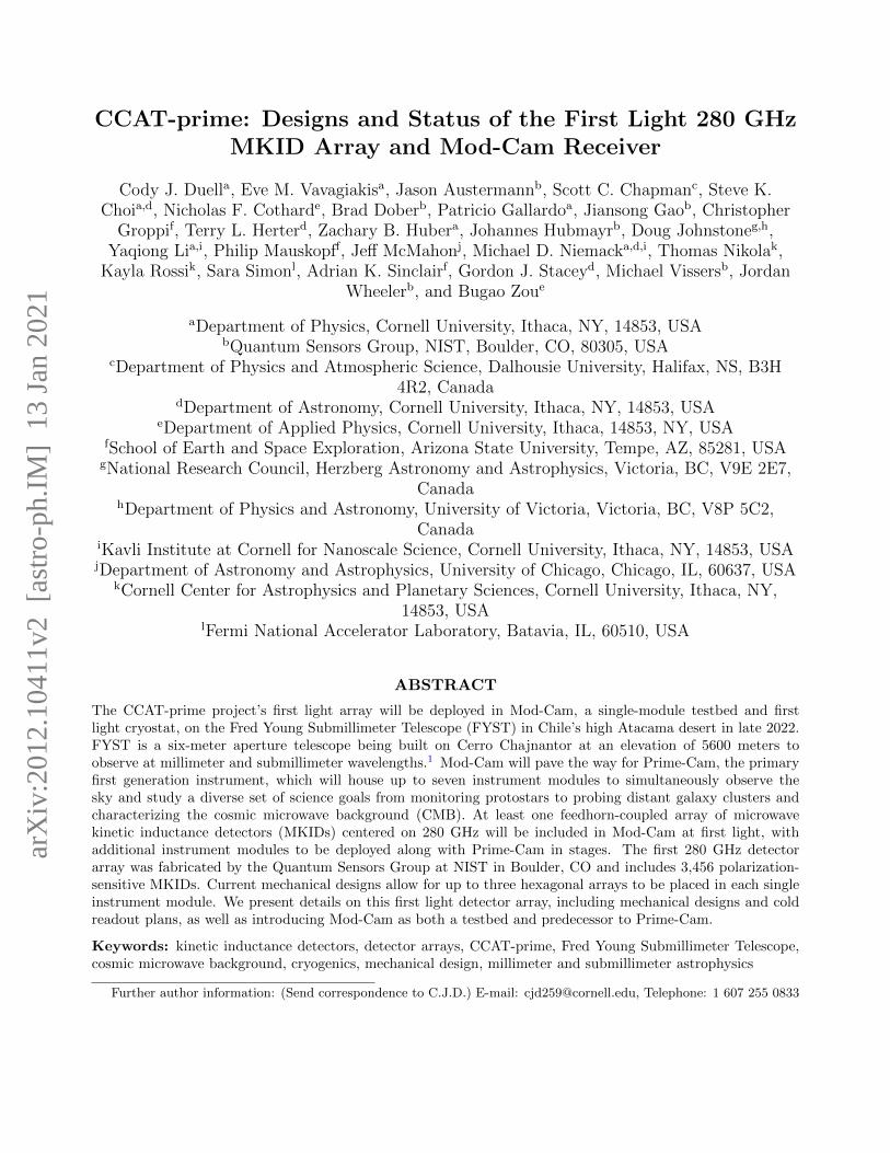
The detector array is being mounted within a focal plane assembly that also holds the aluminum-machinedfeedhorns. This mechanical assembly (shown in Figure 3) serves to set the alignment between the detectorsand the feedhorns, couple the detectors with the RF lines for readout, and provide heatsinking to the dilutionrefrigerator so as to keep the entire assembly stable at the detectors’ 100 mK operating temperature. Thehexagonal design allows for packing three arrays within a single instrument module, keeping all three as nearas possible to the center of the instrument’s focal plane. Designing and machining the mechanical componentsto meet the relatively strict alignment tolerances while minimizing risk of damaging the detector wafer duringcooldowns provided several significant challenges.
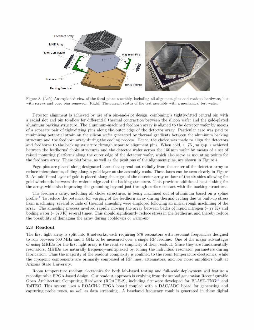
Figure 3. (Left) An exploded view of the focal plane assembly, including all alignment pins and readout hardware, butwith screws and pogo pins removed. (Right) The current status of the test assembly with a mechanical test wafer.
Detector alignment is achieved by use of a pin-and-slot design, combining a tightly-fitted central pin witha radial slot and pin to allow for differential thermal contraction between the silicon wafer and the gold-platedaluminum backing structure. The aluminum-machined feedhorn array is aligned to the detector wafer by meansof a separate pair of tight-fitting pins along the outer edge of the detector array. Particular care was paid tominimizing potential strain on the silicon wafer generated by thermal gradients between the aluminum backingstructure and the feedhorn array during the cooling process. Hence, the choice was made to align the detectorsand feedhorns to the backing structure through separate alignment pins. When cold, a 75 µm gap is achievedbetween the feedhorns’ choke structures and the detector wafer across the 150 mm wafer by means of a set ofraised mounting platforms along the outer edge of the detector wafer, which also serve as mounting points forthe feedhorn array. These platforms, as well as the positions of the alignment pins, are shown in Figure 4.
Pogo pins are placed along designated lanes that spread out radially from the center of the detector array toreduce microphonics, sliding along a gold layer as the assembly cools. These lanes can be seen clearly in Figure2. An additional layer of gold is placed along the edges of the detector array on four of the six sides allowing forgold wirebonds between the wafer’s edge and the backing structure. This provides additional heat sinking forthe array, while also improving the grounding beyond just through surface contact with the backing structure.
The feedhorn array, including all choke structures, is being machined out of aluminum based on a splineprofile.7 To reduce the potential for warping of the feedhorn array during thermal cycling due to built-up stressfrom machining, several rounds of thermal annealing were employed following an initial rough machining of thearray. The annealing process involved rapidly moving the array between baths of liquid nitrogen (∼77 K) andboiling water (∼373 K) several times. This should significantly reduce stress in the feedhorns, and thereby reducethe possibility of damaging the array during cooldowns or warm-up.
2.3 Readout
The first light array is split into 6 networks, each requiring 576 resonators with resonant frequencies designedto run between 500 MHz and 1 GHz to be measured over a single RF feedline. One of the major advantagesof using MKIDs for the first light array is the relative simplicity of their readout. Since they are fundamentallyresonators, MKIDs are naturally frequency-multiplexed by tuning the individual resonator parameters duringfabrication. Thus the majority of the readout complexity is confined to the room temperature electronics, whilethe cryogenic components are primarily comprised of RF lines, attenuators, and low noise amplifiers built atArizona State University.
Room temperature readout electronics for both lab-based testing and full-scale deployment will feature areconfigurable FPGA-based design. Our readout approach is evolving from the second generation ReconfigurableOpen Architecture Computing Hardware (ROACH-2), including firmware developed for BLAST-TNG13 andTolTEC. This system uses a ROACH-2 FPGA board coupled with a DAC/ADC board for generating andcapturing probe tones, as well as data streaming. A baseband frequency comb is generated in these digital
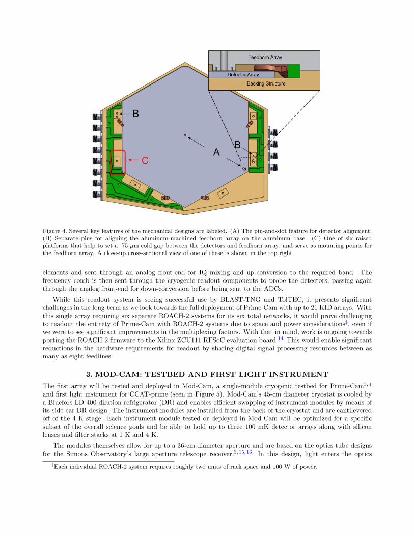
Figure 4. Several key features of the mechanical designs are labeled. (A) The pin-and-slot feature for detector alignment.(B) Separate pins for aligning the aluminum-machined feedhorn array on the aluminum base. (C) One of six raisedplatforms that help to set a 75 µm cold gap between the detectors and feedhorn array. and serve as mounting points forthe feedhorn array. A close-up cross-sectional view of one of these is shown in the top right.
elements and sent through an analog front-end for IQ mixing and up-conversion to the required band. Thefrequency comb is then sent through the cryogenic readout components to probe the detectors, passing againthrough the analog front-end for down-conversion before being sent to the ADCs.
While this readout system is seeing successful use by BLAST-TNG and TolTEC, it presents significantchallenges in the long-term as we look towards the full deployment of Prime-Cam with up to 21 KID arrays. Withthis single array requiring six separate ROACH-2 systems for its six total networks, it would prove challengingto readout the entirety of Prime-Cam with ROACH-2 systems due to space and power considerations‡, even ifwe were to see significant improvements in the multiplexing factors. With that in mind, work is ongoing towardsporting the ROACH-2 firmware to the Xilinx ZCU111 RFSoC evaluation board.14 This would enable significantreductions in the hardware requirements for readout by sharing digital signal processing resources between asmany as eight feedlines.
3. MOD-CAM: TESTBED AND FIRST LIGHT INSTRUMENT
The first array will be tested and deployed in Mod-Cam, a single-module cryogenic testbed for Prime-Cam3,4
and first light instrument for CCAT-prime (seen in Figure 5). Mod-Cam’s 45-cm diameter cryostat is cooled bya Bluefors LD-400 dilution refrigerator (DR) and enables efficient swapping of instrument modules by means ofits side-car DR design. The instrument modules are installed from the back of the cryostat and are cantileveredoff of the 4 K stage. Each instrument module tested or deployed in Mod-Cam will be optimized for a specificsubset of the overall science goals and be able to hold up to three 100 mK detector arrays along with siliconlenses and filter stacks at 1 K and 4 K.
The modules themselves allow for up to a 36-cm diameter aperture and are based on the optics tube designsfor the Simons Observatory’s large aperture telescope receiver.3,15,16 In this design, light enters the optics
‡Each individual ROACH-2 system requires roughly two units of rack space and 100 W of power.
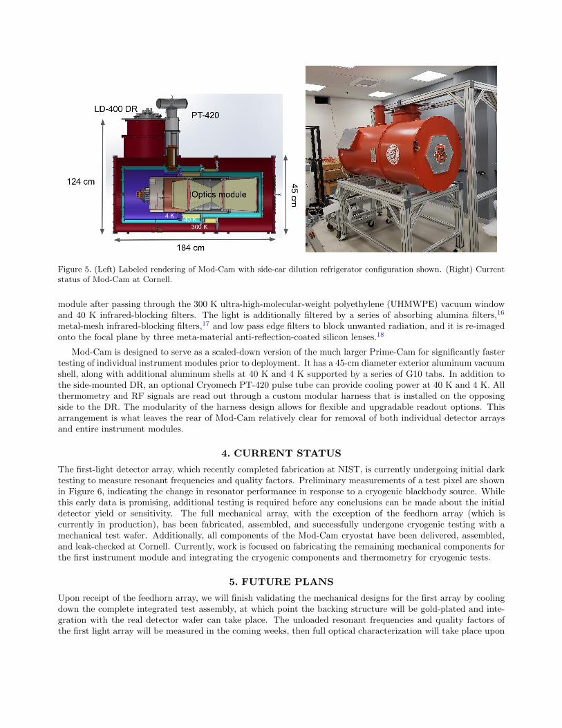
Figure 5. (Left) Labeled rendering of Mod-Cam with side-car dilution refrigerator configuration shown. (Right) Currentstatus of Mod-Cam at Cornell.
module after passing through the 300 K ultra-high-molecular-weight polyethylene (UHMWPE) vacuum windowand 40 K infrared-blocking filters. The light is additionally filtered by a series of absorbing alumina filters,16
metal-mesh infrared-blocking filters,17 and low pass edge filters to block unwanted radiation, and it is re-imagedonto the focal plane by three meta-material anti-reflection-coated silicon lenses.18
Mod-Cam is designed to serve as a scaled-down version of the much larger Prime-Cam for significantly fastertesting of individual instrument modules prior to deployment. It has a 45-cm diameter exterior aluminum vacuumshell, along with additional aluminum shells at 40 K and 4 K supported by a series of G10 tabs. In addition tothe side-mounted DR, an optional Cryomech PT-420 pulse tube can provide cooling power at 40 K and 4 K. Allthermometry and RF signals are read out through a custom modular harness that is installed on the opposingside to the DR. The modularity of the harness design allows for flexible and upgradable readout options. Thisarrangement is what leaves the rear of Mod-Cam relatively clear for removal of both individual detector arraysand entire instrument modules.
4. CURRENT STATUS
The first-light detector array, which recently completed fabrication at NIST, is currently undergoing initial darktesting to measure resonant frequencies and quality factors. Preliminary measurements of a test pixel are shownin Figure 6, indicating the change in resonator performance in response to a cryogenic blackbody source. Whilethis early data is promising, additional testing is required before any conclusions can be made about the initialdetector yield or sensitivity. The full mechanical array, with the exception of the feedhorn array (which iscurrently in production), has been fabricated, assembled, and successfully undergone cryogenic testing with amechanical test wafer. Additionally, all components of the Mod-Cam cryostat have been delivered, assembled,and leak-checked at Cornell. Currently, work is focused on fabricating the remaining mechanical components forthe first instrument module and integrating the cryogenic components and thermometry for cryogenic tests.
5. FUTURE PLANS
Upon receipt of the feedhorn array, we will finish validating the mechanical designs for the first array by coolingdown the complete integrated test assembly, at which point the backing structure will be gold-plated and inte-gration with the real detector wafer can take place. The unloaded resonant frequencies and quality factors ofthe first light array will be measured in the coming weeks, then full optical characterization will take place upon

Figure 6. Preliminary data taken at NIST showing the noise performance (left) and resonator response (right) of a recentlycompleted test pixel as a function of loading power from a cryogenic blackbody. In both cases, optical power is roughlyestimated due to uncertainties in the optical chain, and systematic noise sources have not been removed.
integration with the assembly at Cornell using a Fourier Transform Spectrometer and a cold load. Mod-Camwill soon undergo cryogenic tests in preparation for integration of the first light instrument module.
6. CONCLUSION
CCAT-prime’s first light 280 GHz array and focal plane module is well on its way to completion for use on theupcoming Fred Young Submillimeter Telescope. With nearly 3,500 background-limited, polarization-sensitiveMKIDs coupled to FYST’s high throughput optics within Mod-Cam, it will pave the way for the more than100,000 detectors that will eventually be deployed in Prime-Cam by the CCAT-prime collaboration. We presentedhere the detectors, mechanical designs, and readout plans for this first light array, along with an introductionto and overview of Mod-Cam which will serve as a precursor to Prime-Cam and cryogenic testbed for all ofPrime-Cam’s instrument modules.
ACKNOWLEDGMENTS
CCAT-prime funding has been provided by Cornell University, the Fred M. Young Jr. Charitable Fund, theGerman Research Foundation (DFG) through grant number INST 216/733-1 FUGG, the Univ. of Cologne,the Univ. of Bonn, and the Canadian Atacama Telescope Consortium. EMV acknowledges support from theNSF GRFP under Grant No. DGE-1650441. MDN acknowledges support from NSF award AST-1454881. NFCacknowledges support from a NASA Space Technology Research Fellowship. SKC acknowledges support fromNSF award AST-2001866. YL acknowledges support from the Kavli Institute at Cornell for Nanoscale Science.
Work supported by the Fermi National Accelerator Laboratory, managed and operated by Fermi ResearchAlliance, LLC under Contract No. DE-AC02-07CH11359 with the U.S. Department of Energy. The U.S. Govern-ment retains and the publisher, by accepting the article for publication, acknowledges that the U.S. Governmentretains a non-exclusive, paid-up, irrevocable, world-wide license to publish or reproduce the published form ofthis manuscript, or allow others to do so, for U.S. Government purposes.
REFERENCES
[1] Stacey, G. J., Aravena, M., Basu, K., Battaglia, N., Beringue, B., Bertoldi, F., Bond, J. R., Breysse,P., Bustos, R., Chapman, S., Chung, D. T., Cothard, N., Erler, J., Fich, M., Foreman, S., Gallardo, P.,Giovanelli, R., Graf, U. U., Haynes, M. P., Herrera-Camus, R., Herter, T. L., Hlozek, R., Johnstone, D.,Keating, L., Magnelli, B., Meerburg, D., Meyers, J., Murray, N., Niemack, M., Nikola, T., Nolta, M.,Parshley, S. C., Riechers, D. A., Schilke, P., Scott, D., Stein, G., Stevens, J., Stutzki, J., Vavagiakis,

E. M., and Viero, M. P., “CCAT-Prime: science with an ultra-widefield submillimeter observatory on CerroChajnantor,” in [Ground-based and Airborne Telescopes VII ], Marshall, H. K. and Spyromilio, J., eds.,10700, 482 – 501, International Society for Optics and Photonics, SPIE (2018).
[2] Aravena, M., Austermann, J., Basu, K., Battaglia, N., Beringue, B., Bertoldi, F., Bond, J. R., Breysse,P., Bustos, R., Chapman, S., Choi, S., Chung, D., Cothard, N., Dober, B., Duell, C., Duff, S., Dunner,R., Erler, J., Fich, M., Fissel, L., Foreman, S., Gallardo, P., Gao, J., Giovanelli, R., Graf, U., Haynes,M., Herter, T., Hilton, G., Hlozek, R., Hubmayr, J., Johnstone, D., Keating, L., Komatsu, E., Magnelli,B., Mauskopf, P., McMahon, J., Meerburg, P. D., Meyers, J., Murray, N., Niemack, M., Nikola, T., Nolta,M., Parshley, S., Puddu, R., Riechers, D., Rosolowsky, E., Simon, S., Stacey, G., Stevens, J., Stutzki, J.,Engelen, A. V., Vavagiakis, E., Viero, M., Vissers, M., Walker, S., and Zou, B., “Astro2020 apc white paper:The ccat-prime submillimeter observatory,” (2019).
[3] Vavagiakis, E. M., Ahmed, Z., Ali, A., Basu, K., Battaglia, N., Bertoldi, F., Bond, R., Bustos, R., Chapman,S. C., Chung, D., Coppi, G., Cothard, N. F., Dicker, S., Duell, C. J., Duff, S. M., Erler, J., Fich, M., Galitzki,N., Gallardo, P. A., Henderson, S. W., Herter, T. L., Hilton, G., Hubmayr, J., Irwin, K. D., Koopman, B. J.,McMahon, J., Murray, N., Niemack, M. D., Nikola, T., Nolta, M., Orlowski-Scherer, J., Parshley, S. C.,Riechers, D. A., Rossi, K., Scott, D., Sierra, C., Silva-Feaver, M., Simon, S. M., Stacey, G. J., Stevens, J. R.,Ullom, J. N., Vissers, M. R., Walker, S., Wollack, E. J., Xu, Z., and Zhu, N., “Prime-Cam: a first-lightinstrument for the CCAT-prime telescope,” in [Millimeter, Submillimeter, and Far-Infrared Detectors andInstrumentation for Astronomy IX ], Zmuidzinas, J. and Gao, J.-R., eds., 10708, 187 – 202, InternationalSociety for Optics and Photonics, SPIE (2018).
[4] Choi, S. K., Austermann, J., Basu, K., Battaglia, N., Bertoldi, F., Chung, D. T., Cothard, N. F., Duff,S., Duell, C. J., Gallardo, P. A., Gao, J., Herter, T., Hubmayr, J., Niemack, M. D., Nikola, T., Riechers,D., Rossi, K., Stacey, G. J., Stevens, J. R., Vavagiakis, E. M., Vissers, M., and Walker, S., “Sensitivityof the Prime-Cam Instrument on the CCAT-Prime Telescope,” Journal of Low Temperature Physics 199,1089–1097 (May 2020).
[5] Hubmayr, J., Beall, J., Becker, D., Cho, H.-M., Devlin, M., Dober, B., Groppi, C., Hilton, G. C., Irwin,K. D., Li, D., Mauskopf, P., Pappas, D. P., Van Lanen, J., Vissers, M. R., Wang, Y., Wei, L. F., andGao, J., “Photon-noise limited sensitivity in titanium nitride kinetic inductance detectors,” Applied PhysicsLetters 106(7), 073505 (2015).
[6] Austermann, J., Beall, J., Bryan, S. A., Dober, B., Gao, J., Hilton, G., Hubmayr, J., Mauskopf, P.,McKenney, C., Simon, S. M., Ullom, J., Vissers, M., and Wilson, G. W., “Large format arrays of kineticinductance detectors for the TolTEC millimeter-wave imaging polarimeter (Conference Presentation),” in[Millimeter, Submillimeter, and Far-Infrared Detectors and Instrumentation for Astronomy IX ], 10708,107080U, International Society for Optics and Photonics (July 2018).
[7] Austermann, J. E., Beall, J. A., Bryan, S. A., Dober, B., Gao, J., Hilton, G., Hubmayr, J., Mauskopf,P., McKenney, C. M., Simon, S. M., Ullom, J. N., Vissers, M. R., and Wilson, G. W., “Millimeter-WavePolarimeters Using Kinetic Inductance Detectors for TolTEC and Beyond,” Journal of Low TemperaturePhysics 193, 120–127 (Nov. 2018).
[8] Cothard, N. F., Choi, S. K., Duell, C. J., Herter, T., Hubmayr, J., McMahon, J., Niemack, M. D., Nikola,T., Sierra, C., Stacey, G. J., Vavagiakis, E. M., Wollack, E. J., and Zou, B., “The Design of the CCAT-primeEpoch of Reionization Spectrometer Instrument,” Journal of Low Temperature Physics 199, 898–907 (May2020).
[9] Mazin, B. A., Day, P. K., LeDuc, H. G., Vayonakis, A., and Zmuidzinas, J., “Superconducting kineticinductance photon detectors,” in [Highly Innovative Space Telescope Concepts ], MacEwen, H. A., ed., 4849,283 – 293, International Society for Optics and Photonics, SPIE (2002).
[10] Day, P. K., LeDuc, H. G., Mazin, B. A., Vayonakis, A., and Zmuidzinas, J., “A broadband superconductingdetector suitable for use in large arrays,” Nature 425, 817–821 (Oct. 2003).
[11] Dober, B., Austermann, J. A., Beall, J. A., Becker, D., Che, G., Cho, H. M., Devlin, M., Duff, S. M.,Galitzki, N., Gao, J., Groppi, C., Hilton, G. C., Hubmayr, J., Irwin, K. D., McKenney, C. M., Li, D.,Lourie, N., Mauskopf, P., Vissers, M. R., and Wang, Y., “Optical Demonstration of THz, Dual-PolarizationSensitive Microwave Kinetic Inductance Detectors,” Journal of Low Temperature Physics 184, 173–179(July 2016).
[12] Galitzki, N., Ade, P., Angile, F. E., Ashton, P., Austermann, J., Billings, T., Che, G., Cho, H.-M., Davis,K., Devlin, M., Dicker, S., Dober, B. J., Fissel, L. M., Fukui, Y., Gao, J., Gordon, S., Groppi, C. E.,Hillbrand, S., Hilton, G. C., Hubmayr, J., Irwin, K. D., Klein, J., Li, D., Li, Z.-Y., Lourie, N. P., Lowe,I., Mani, H., Martin, P. G., Mauskopf, P., McKenney, C., Nati, F., Novak, G., Pascale, E., Pisano, G.,Santos, F. P., Scott, D., Sinclair, A., Soler, J. D., Tucker, C., Underhill, M., Vissers, M., and Williams, P.,“Instrumental performance and results from testing of the BLAST-TNG receiver, submillimeter optics, andMKID detector arrays,” in [Millimeter, Submillimeter, and Far-Infrared Detectors and Instrumentation forAstronomy VIII ], Holland, W. S. and Zmuidzinas, J., eds., 9914, 108 – 118, International Society for Opticsand Photonics, SPIE (2016).
[13] Gordon, S., Dober, B., Sinclair, A., Rowe, S., Bryan, S., Mauskopf, P., Austermann, J., Devlin, M., Dicker,S., Gao, J., Hilton, G. C., Hubmayr, J., Jones, G., Klein, J., Lourie, N. P., McKenney, C., Nati, F., Soler,J. D., Strader, M., and Vissers, M., “An open source, fpga-based lekid readout for blast-tng: Pre-flightresults,” Journal of Astronomical Instrumentation 05(04), 1641003 (2016).
[14] Sinclair, A. K., Browning, T., Miles, L. R., Jamison, T. L., Stephenson, R., Hoh, J., Bryan, S., Mauskopf,P. D., Smith, J., Bradley, D., and Mazin, B., “Development of a Reconfigurable Readout for Superconduct-ing Arrays (Conference Poster),” in [Proceedings of the 18th International Workshop on Low TemperatureDetectors ], Journal of Low Temperature Physics (July 2019).
[15] Zhu, N., Orlowski-Scherer, J. L., Xu, Z., Ali, A., Arnold, K. S., Ashton, P. C., Coppi, G., Devlin, M. J.,Dicker, S., Galitzki, N., Gallardo, P. A., Henderson, S. W., Ho, S.-P. P., Hubmayr, J., Keating, B., Lee,A. T., Limon, M., Lungu, M., Mauskopf, P. D., May, A. J., McMahon, J., Niemack, M. D., Piccirillo, L.,Puglisi, G., Rao, M. S., Salatino, M., Silva-Feaver, M., Simon, S. M., Staggs, S., Thornton, R., Ullom,J. N., Vavagiakis, E. M., Westbrook, B., and Wollack, E. J., “Simons Observatory large aperture telescopereceiver design overview,” in [Millimeter, Submillimeter, and Far-Infrared Detectors and Instrumentationfor Astronomy IX ], Zmuidzinas, J. and Gao, J.-R., eds., 10708, 259 – 273, International Society for Opticsand Photonics, SPIE (2018).
[16] Dicker, S. R., Gallardo, P. A., Gudmundsson, J. E., Mauskopf, P. D., Ali, A., Ashton, P. C., Coppi, G.,Devlin, M. J., Galitzki, N., Ho, S. P., Hill, C. A., Hubmayr, J., Keating, B., Lee, A. T., Limon, M., Matsuda,F., McMahon, J., Niemack, M. D., Orlowski-Scherer, J. L., Piccirillo, L., Salatino, M., Simon, S. M., Staggs,S. T., Thornton, R., Ullom, J. N., Vavagiakis, E. M., Wollack, E. J., Xu, Z., and Zhu, N., “Cold opticaldesign for the large aperture Simons’ Observatory telescope,” in [Ground-based and Airborne TelescopesVII ], Marshall, H. K. and Spyromilio, J., eds., 10700, 1064 – 1076, International Society for Optics andPhotonics, SPIE (2018).
[17] Tucker, C. E. and Ade, P. A. R., “Thermal filtering for large aperture cryogenic detector arrays,” in[Millimeter and Submillimeter Detectors and Instrumentation for Astronomy III ], Zmuidzinas, J., Holland,W. S., Withington, S., and Duncan, W. D., eds., 6275, 239 – 247, International Society for Optics andPhotonics, SPIE (2006).
[18] Datta, R., Munson, C. D., Niemack, M. D., McMahon, J. J., Britton, J., Wollack, E. J., Beall, J., Devlin,M. J., Fowler, J., Gallardo, P., Hubmayr, J., Irwin, K., Newburgh, L., Nibarger, J. P., Page, L., Qui-jada, M. A., Schmitt, B. L., Staggs, S. T., Thornton, R., and Zhang, L., “Large-aperture wide-bandwidthantireflection-coated silicon lenses for millimeter wavelengths,” Appl. Opt. 52, 8747–8758 (Dec 2013).