cc mis installation and maintenance
TRANSCRIPT

Call Center Management Information SystemCC MIS Installation and Maintenance
Release 6.0.1 Standard 2.0 May 2007
297-2671-545

Call Center Management Information SystemCC MIS Installation and Maintenance
Publication number: 297-2671-545
Product release: 6.0.1
Document release: Standard 2.0Date: May 2007
Copyright © 2007 Nortel Networks. All Rights Reserved
The information in this document is subject to change without notice. The statements, configurations, technical data, and recommendations in this document are believed to be accurate and reliable, but are presented without express or implied warranty. Users must take full responsibility for their applications of any products specified in this document. The information in this document is proprietary to Nortel Networks.
Trademarks
*Nortel Networks, the Nortel Networks logo, the Globemark, ACD, DMS, and Meridian Call Center MIS are trademarks of Nortel Networks.
*Microsoft, MS, MS-DOS, Windows, Windows NT, Windows 95, Windows 98, Windows 2000, Windows XP, and Microsoft Exchange are registered trademarks of Microsoft Corporation.
Red Hat Enterprise Linux is a trademark of Red Hat Inc.
Adobe and Acrobat are registered trademarks of Adobe Systems Incorporated.All other trademarks and registered trademarks are the property of their respective owners.
The process of transmitting data and call messaging between the Call Center Management Information System server and the switch or the system is proprietary to Nortel Networks. Any other use of the data and the transmission process is a violation of the user license unless specifically authorized in writing by Nortel Networks prior to such use. Violations of the license by alternative usage of any portion of this process or the related hardware constitutes grounds for an immediate termination of the license and Nortel Networks reserves the right to seek all allowable remedies for such breach.
European Regulatory Compliance and CE Marking
The equipment is CE marked, identifying compliance with the relevant EU Directives, 89/336/EEC for ElectroMagnetic Compatibility and 73/23/EEC for Safety.

This product is intended for deployment in a light industrial, non-domestic environment and complies with the relevant EMC standards, EN55022 (class A) and EN50082-1. Since this is class A equipment, in a domestic environment this equipment may cause radio interference in which case the user may be required to take adequate measures.


CC MIS Installation and Maintenance v
Revision history
May 2007 Standard 2.0 for Release 6.0.1
June 2005 Standard 1.0 for Release 6.0.
June 2002 Standard version for Release 5.2.

vi Call Center Management Information System
Standard 2.0

CC MIS Installation and Maintenance vii
Contents
1 How to get help 13
2 About this document 15
3 CC MIS requirements 21Overview. . . . . . . . . . . . . . . . . . . . . . . . . . . . . . . . . . . . . . . . . . . . . . . . . . . 22Hardware requirements for the CC MIS server . . . . . . . . . . . . . . . . . . . . . 23Operating system requirements . . . . . . . . . . . . . . . . . . . . . . . . . . . . . . . . . 28Third-party software guidelines . . . . . . . . . . . . . . . . . . . . . . . . . . . . . . . . . 29Remote support . . . . . . . . . . . . . . . . . . . . . . . . . . . . . . . . . . . . . . . . . . . . . . 33Technical support . . . . . . . . . . . . . . . . . . . . . . . . . . . . . . . . . . . . . . . . . . . . 34Preinstallation requirements . . . . . . . . . . . . . . . . . . . . . . . . . . . . . . . . . . . . 35Data migration . . . . . . . . . . . . . . . . . . . . . . . . . . . . . . . . . . . . . . . . . . . . . . 55
4 CC MIS overview 57Description of CC MIS . . . . . . . . . . . . . . . . . . . . . . . . . . . . . . . . . . . . . . . . 58CC MIS interfaces . . . . . . . . . . . . . . . . . . . . . . . . . . . . . . . . . . . . . . . . . . . 59Features added or modified in Release 6.0 . . . . . . . . . . . . . . . . . . . . . . . . . 61
5 Installing CC MIS 67Installing the CC MIS server software . . . . . . . . . . . . . . . . . . . . . . . . . . . . 68Installing the CC MIS client software . . . . . . . . . . . . . . . . . . . . . . . . . . . . 86Upgrading the CC MIS server operating system . . . . . . . . . . . . . . . . . . . . 99
6 Accessing maintenance functions 105Introduction to the Maintenance and Administration interface . . . . . . . . 106Setting up a new CC MIS system (overview). . . . . . . . . . . . . . . . . . . . . . 112Logging on . . . . . . . . . . . . . . . . . . . . . . . . . . . . . . . . . . . . . . . . . . . . . . . . 114Changing your password . . . . . . . . . . . . . . . . . . . . . . . . . . . . . . . . . . . . . 117

Contents Standard 2.0
viii Call Center Management Information System
Logging off . . . . . . . . . . . . . . . . . . . . . . . . . . . . . . . . . . . . . . . . . . . . . . . . 119Maintenance and Administration menus and screens. . . . . . . . . . . . . . . . 120
7 Configuring the CC MIS application 131Introduction. . . . . . . . . . . . . . . . . . . . . . . . . . . . . . . . . . . . . . . . . . . . . . . . 132Accessing the Configuration main menu . . . . . . . . . . . . . . . . . . . . . . . . . 133System configuration . . . . . . . . . . . . . . . . . . . . . . . . . . . . . . . . . . . . . . . . 135Switch link configuration . . . . . . . . . . . . . . . . . . . . . . . . . . . . . . . . . . . . . 140Terminal server configuration . . . . . . . . . . . . . . . . . . . . . . . . . . . . . . . . . 148Disk storage . . . . . . . . . . . . . . . . . . . . . . . . . . . . . . . . . . . . . . . . . . . . . . . 151SNMP configuration . . . . . . . . . . . . . . . . . . . . . . . . . . . . . . . . . . . . . . . . . 154System configuration reports . . . . . . . . . . . . . . . . . . . . . . . . . . . . . . . . . . 157
8 Shutdown, startup, reboot, and power down 161Introduction. . . . . . . . . . . . . . . . . . . . . . . . . . . . . . . . . . . . . . . . . . . . . . . . 162Shut down the CC MIS application . . . . . . . . . . . . . . . . . . . . . . . . . . . . . 164Start up the CC MIS application. . . . . . . . . . . . . . . . . . . . . . . . . . . . . . . . 166Power down the system . . . . . . . . . . . . . . . . . . . . . . . . . . . . . . . . . . . . . . 168Power up the system . . . . . . . . . . . . . . . . . . . . . . . . . . . . . . . . . . . . . . . . . 170Reboot the system. . . . . . . . . . . . . . . . . . . . . . . . . . . . . . . . . . . . . . . . . . . 172
9 Backing up, restoring, and importing data 175Introduction. . . . . . . . . . . . . . . . . . . . . . . . . . . . . . . . . . . . . . . . . . . . . . . . 176Backup directory. . . . . . . . . . . . . . . . . . . . . . . . . . . . . . . . . . . . . . . . . . . . 178Backing up customer data. . . . . . . . . . . . . . . . . . . . . . . . . . . . . . . . . . . . . 181Restoring customer data . . . . . . . . . . . . . . . . . . . . . . . . . . . . . . . . . . . . . . 186Importing data. . . . . . . . . . . . . . . . . . . . . . . . . . . . . . . . . . . . . . . . . . . . . . 191
10 Local partitions 197Introduction. . . . . . . . . . . . . . . . . . . . . . . . . . . . . . . . . . . . . . . . . . . . . . . . 198Partition task list . . . . . . . . . . . . . . . . . . . . . . . . . . . . . . . . . . . . . . . . . . . . 203Adding and deleting partitions . . . . . . . . . . . . . . . . . . . . . . . . . . . . . . . . . 209Partition options . . . . . . . . . . . . . . . . . . . . . . . . . . . . . . . . . . . . . . . . . . . . 213Disk allocation . . . . . . . . . . . . . . . . . . . . . . . . . . . . . . . . . . . . . . . . . . . . . 220Storage Calculator. . . . . . . . . . . . . . . . . . . . . . . . . . . . . . . . . . . . . . . . . . . 224Connection parameters . . . . . . . . . . . . . . . . . . . . . . . . . . . . . . . . . . . . . . . 229

May 2007 Contents
CC MIS Installation and Maintenance ix
Serial terminals . . . . . . . . . . . . . . . . . . . . . . . . . . . . . . . . . . . . . . . . . . . . . 231Wallboards . . . . . . . . . . . . . . . . . . . . . . . . . . . . . . . . . . . . . . . . . . . . . . . . 233Static LAN Terminals . . . . . . . . . . . . . . . . . . . . . . . . . . . . . . . . . . . . . . . . 236Master supervisor privileges . . . . . . . . . . . . . . . . . . . . . . . . . . . . . . . . . . . 238Partition startup and shutdown . . . . . . . . . . . . . . . . . . . . . . . . . . . . . . . . . 248
11 Networked CC MIS 251Introduction. . . . . . . . . . . . . . . . . . . . . . . . . . . . . . . . . . . . . . . . . . . . . . . . 252System configuration . . . . . . . . . . . . . . . . . . . . . . . . . . . . . . . . . . . . . . . . 258Physical network configuration . . . . . . . . . . . . . . . . . . . . . . . . . . . . . . . . 259Partition configuration . . . . . . . . . . . . . . . . . . . . . . . . . . . . . . . . . . . . . . . 266Virtual network configuration . . . . . . . . . . . . . . . . . . . . . . . . . . . . . . . . . 271
12 Monitoring system functions 277Introduction. . . . . . . . . . . . . . . . . . . . . . . . . . . . . . . . . . . . . . . . . . . . . . . . 278Logs . . . . . . . . . . . . . . . . . . . . . . . . . . . . . . . . . . . . . . . . . . . . . . . . . . . . . 279View system monitor . . . . . . . . . . . . . . . . . . . . . . . . . . . . . . . . . . . . . . . . 287Trace Switch Link. . . . . . . . . . . . . . . . . . . . . . . . . . . . . . . . . . . . . . . . . . . 303Physical Network Login . . . . . . . . . . . . . . . . . . . . . . . . . . . . . . . . . . . . . . 319
13 Switch configuration data updates 323Introduction. . . . . . . . . . . . . . . . . . . . . . . . . . . . . . . . . . . . . . . . . . . . . . . . 324Accessing the Update Switch Configuration Data screen . . . . . . . . . . . . 325
14 SNMP MIB transfer 327Introduction. . . . . . . . . . . . . . . . . . . . . . . . . . . . . . . . . . . . . . . . . . . . . . . . 328Accessing the SNMP Transfer screen . . . . . . . . . . . . . . . . . . . . . . . . . . . 329
A Switch link datafill requirements 333Introduction. . . . . . . . . . . . . . . . . . . . . . . . . . . . . . . . . . . . . . . . . . . . . . . . 334Office parameters . . . . . . . . . . . . . . . . . . . . . . . . . . . . . . . . . . . . . . . . . . . 335Data link datafill . . . . . . . . . . . . . . . . . . . . . . . . . . . . . . . . . . . . . . . . . . . . 336Standard datafill example . . . . . . . . . . . . . . . . . . . . . . . . . . . . . . . . . . . . . 344

Contents Standard 2.0
x Call Center Management Information System
B TCP/X.25 bridge devices 351Introduction. . . . . . . . . . . . . . . . . . . . . . . . . . . . . . . . . . . . . . . . . . . . . . . . 352TCP/X.25 bridge solutions . . . . . . . . . . . . . . . . . . . . . . . . . . . . . . . . . . . . 353
C TCP/IP switch links using ARN 355Introduction. . . . . . . . . . . . . . . . . . . . . . . . . . . . . . . . . . . . . . . . . . . . . . . . 356Regional requirements . . . . . . . . . . . . . . . . . . . . . . . . . . . . . . . . . . . . . . . 357Purpose . . . . . . . . . . . . . . . . . . . . . . . . . . . . . . . . . . . . . . . . . . . . . . . . . . . 359Feature definition . . . . . . . . . . . . . . . . . . . . . . . . . . . . . . . . . . . . . . . . . . . 360Before you begin. . . . . . . . . . . . . . . . . . . . . . . . . . . . . . . . . . . . . . . . . . . . 364Installing the Advanced Remote Node (ARN) . . . . . . . . . . . . . . . . . . . . . 365Configuring the Ethernet link on the ARN. . . . . . . . . . . . . . . . . . . . . . . . 379Installing Site Manager . . . . . . . . . . . . . . . . . . . . . . . . . . . . . . . . . . . . . . . 388Configuring an X.25 link on the ARN . . . . . . . . . . . . . . . . . . . . . . . . . . . 396CC MIS TCP/IP switch link configuration. . . . . . . . . . . . . . . . . . . . . . . . 422Postinstallation activities . . . . . . . . . . . . . . . . . . . . . . . . . . . . . . . . . . . . . 426References. . . . . . . . . . . . . . . . . . . . . . . . . . . . . . . . . . . . . . . . . . . . . . . . . 430
D System Configuration reports 431Introduction. . . . . . . . . . . . . . . . . . . . . . . . . . . . . . . . . . . . . . . . . . . . . . . . 432Available reports. . . . . . . . . . . . . . . . . . . . . . . . . . . . . . . . . . . . . . . . . . . . 433
E System Log messages 455Standard error messages . . . . . . . . . . . . . . . . . . . . . . . . . . . . . . . . . . . . . 456General messages . . . . . . . . . . . . . . . . . . . . . . . . . . . . . . . . . . . . . . . . . . . 460MAPA messages. . . . . . . . . . . . . . . . . . . . . . . . . . . . . . . . . . . . . . . . . . . . 467DMSLINK messages . . . . . . . . . . . . . . . . . . . . . . . . . . . . . . . . . . . . . . . . 482CCLINK messages . . . . . . . . . . . . . . . . . . . . . . . . . . . . . . . . . . . . . . . . . . 495RPTGEN messages. . . . . . . . . . . . . . . . . . . . . . . . . . . . . . . . . . . . . . . . . . 497CFGDB messages . . . . . . . . . . . . . . . . . . . . . . . . . . . . . . . . . . . . . . . . . . . 499CFGMGR messages . . . . . . . . . . . . . . . . . . . . . . . . . . . . . . . . . . . . . . . . . 501USRIF messages . . . . . . . . . . . . . . . . . . . . . . . . . . . . . . . . . . . . . . . . . . . . 514STSMGR messages . . . . . . . . . . . . . . . . . . . . . . . . . . . . . . . . . . . . . . . . . 520CFGUTIL messages . . . . . . . . . . . . . . . . . . . . . . . . . . . . . . . . . . . . . . . . . 525DMS Simulator messages . . . . . . . . . . . . . . . . . . . . . . . . . . . . . . . . . . . . . 531WINSERVER messages . . . . . . . . . . . . . . . . . . . . . . . . . . . . . . . . . . . . . . 540AGE messages . . . . . . . . . . . . . . . . . . . . . . . . . . . . . . . . . . . . . . . . . . . . . 544

May 2007 Contents
CC MIS Installation and Maintenance xi
BAR messages . . . . . . . . . . . . . . . . . . . . . . . . . . . . . . . . . . . . . . . . . . . . . 547WALLBOARD messages. . . . . . . . . . . . . . . . . . . . . . . . . . . . . . . . . . . . . 551MAINT messages . . . . . . . . . . . . . . . . . . . . . . . . . . . . . . . . . . . . . . . . . . . 552SCHEDULER messages. . . . . . . . . . . . . . . . . . . . . . . . . . . . . . . . . . . . . . 557DDBSERV messages . . . . . . . . . . . . . . . . . . . . . . . . . . . . . . . . . . . . . . . . 558
F Historical database 561

Contents Standard 2.0
xii Call Center Management Information System

CC MIS Installation and Maintenance 13
C h a p t e r 1
How to get help
This section explains how to get help for Nortel products and services.
Getting help from the Nortel Web site
The best way to get technical support for Nortel products is from the Nortel Technical Support Web site:
www.nortel.com/support
This site provides quick access to software, documentation, bulletins, and tools to address issues with Nortel products. From this site, you can:
download software and related toolsdownload technical documents, release notes, and product bulletinssign up for automatic notification of new software and documentationsearch the Technical Support Web site and Nortel Knowledge Base for answers to technical issuesopen and manage technical support cases
Getting help over the phone from a Nortel Solutions Center
If you do not find the information you require on the Nortel Technical Support Web site, and you have a Nortel support contract, you can also get help over the phone from a Nortel Solutions Center.
In North America, call 1-800-4NORTEL (1-800-466-7835).

How to get help Standard 2.0
14 Call Center Management Information System
Outside North America, go to the following Web site to obtain the phone number for your region:
www.nortel.com/callus
Getting help from a specialist by using an Express Routing Code
You can use an Express Routing Code (ERC) to quickly route your call to the appropriate support specialist. To locate the ERC for your product or service, go to:
www.nortel.com/erc
Getting help through a Nortel distributor or reseller
If you purchased a service contract for your Nortel product from a distributor or authorized reseller, contact the technical support staff for that distributor or reseller.

CC MIS Installation and Maintenance 15
C h a p t e r 2
About this document
In this chapterSubject . . . . . . . . . . . . . . . . . . . . . . . . . . . . . . . . . . . . . . . . . . . . . . . . . . 16
Applicable systems . . . . . . . . . . . . . . . . . . . . . . . . . . . . . . . . . . . . . . . . . 16
Intended audience . . . . . . . . . . . . . . . . . . . . . . . . . . . . . . . . . . . . . . . . . 16
Conventions . . . . . . . . . . . . . . . . . . . . . . . . . . . . . . . . . . . . . . . . . . . . . . 16
Related information . . . . . . . . . . . . . . . . . . . . . . . . . . . . . . . . . . . . . . . . . 18

About this document Standard 2.0
16 Call Center Management Information System
Subject
This Nortel Technical Publication (NTP) is an operations guideline for the systems maintenance engineer of a Call Center Management Information System (CC MIS) linked to an MSL-100 (Meridian 1 Options 111-211), Digital Multiplex Switch (DMS)-500, or DMS-100 supporting the Batch Change Supplement (BCS) 35 and BCS 43 protocol versions.
The ACD-MIS Interface Specification version that corresponds to each BCS version is as follows:
BCS 35 = Version 9BCS 43 = Version 11
Nortel recommends that you use BCS 43 (if available) on your switch.
Applicable systems
The CC MIS application manages the agents who handle Automatic Call Distribution (ACD) calls. The CC MIS is linked to an MSL-100 (Meridian 1 Options 111-211), DMS-500, or DMS-100 switch.
Intended audience
This document contains procedures to help system engineers maintain the CC MIS system. This document is also a resource for anyone involved in the planning, installation, configuration, or maintenance of the CC MIS application.
Conventions
The switch supporting CC MIS (the MSL-100, the DMS-500, or the DMS-100) is called a DMS-ACD throughout this NTP.

May 2007 About this document
CC MIS Installation and Maintenance 17
Table 1 lists the typographic conventions that are used throughout this guide.
Note: The function keys associated with a command are listed on the lower portion of the appropriate screen. Procedures in this NTP provide the name of the function key. The screens show examples of function keys with their associated commands. The function key number depends on the type of terminal and emulation mode being used. See each program screen for the actual function key to press to select the applicable command.
Table 2 lists typographic conventions that are used in the procedures in this guide.
Table 1: Typographic conventions
Key sequence Function
<Return> Words in angled brackets represent a specific key on your keyboard that you press.
[Commands] Words in square brackets represent one of the keys available to you from the function key menu.
Table 2: Conventions used in procedures
Key sequence Function
Type xyz Bold letters represent the keys that you press in the action part of the procedure. <enter> means that you press the Enter key after you press the function key.
Notice Words in this font represent a system response to the actions in the procedure.

About this document Standard 2.0
18 Call Center Management Information System
Related information
This section explains where you can find additional information about CC MIS.
NTPsThe following NTPs contain additional information to supplement this document:
CC MIS System Description (297-2671-150)CC MIS Getting Started Guide (297-2671-175)CC MIS Release Notes (297-2671-211)ACD MIS Interface Specifications, Version 11 (NT MIS-Q209-2) DMS-100 Common Customer Data Schema (297-1001-451)MDC Customer Data Schema (297-2001-451)Meridian SL-100 ACD General Description (555-4101-100)Meridian SL-100 ACD Load Management (555-4101-102)Meridian SL-100 ACD Management Information Interface (555-4101-103)Meridian SL-100 ACD Feature Operation and Testing (555-4101-300)Meridian SL-100 ACD MMI and Feature Implementation (555-4101-310)Meridian SL-100 Network ACD General Description (555-8101-100)
For more information about ACD, see the following NTPs:
ACD Product Guide (297-2041-010)ACD Server Product Guide (297-2041-011) ACD Planning and Engineering Guide (297-2041-101)ACD Planning and Engineering Guide - Canada (297-2041-104) ACD Administration Guide (297-2041-301)

May 2007 About this document
CC MIS Installation and Maintenance 19
ACD Translations (297-2041-350)ACD Maintenance Guide (297-2041-500) ACD Trouble Locating and Clearing Procedures (297-2041-503)M5212 ACD Set General Description (297-2041-900) ACD End-User Load Management (297-2041-901) Network ACD General Description (up to BCS 34) (555-8101-100)
OnlineTo access Nortel documentation online, click the Technical Documentation link under Support on the Nortel home page:
www.nortel.com/documentation
CD-ROMTo obtain Nortel documentation on CD-ROM, contact your Nortel customer representative.

About this document Standard 2.0
20 Call Center Management Information System

CC MIS Installation and Maintenance 21
C h a p t e r 3
CC MIS requirements
In this chapterOverview . . . . . . . . . . . . . . . . . . . . . . . . . . . . . . . . . . . . . . . . . . . . . . . . . 22
Hardware requirements for the CC MIS server . . . . . . . . . . . . . . . . . . . . 23
Operating system requirements . . . . . . . . . . . . . . . . . . . . . . . . . . . . . . . 28
Third-party software guidelines. . . . . . . . . . . . . . . . . . . . . . . . . . . . . . . . 29
Remote support . . . . . . . . . . . . . . . . . . . . . . . . . . . . . . . . . . . . . . . . . . . 33
Technical support . . . . . . . . . . . . . . . . . . . . . . . . . . . . . . . . . . . . . . . . . . 34
Preinstallation requirements . . . . . . . . . . . . . . . . . . . . . . . . . . . . . . . . . . 35
Data migration. . . . . . . . . . . . . . . . . . . . . . . . . . . . . . . . . . . . . . . . . . . . . 55

CC MIS requirements Standard 2.0
22 Call Center Management Information System
Overview
The Call Center Management Information System (CC MIS) application manages the agents who handle Automatic Call Distribution (ACD) calls.
Before you install the CC MIS application, ensure that the system meets the following requirements and guidelines:
hardware requirements operating system requirementssoftware requirementsthird-party software guidelinespreinstallation requirements
You cannot upgrade a system from Release 5.2 to Release 6.0; however, you can import data from a Release 5.2 system to a Release 6.0 system using an import tool that is available in CC MIS Release 6.0. For more information, see “Data migration” on page 55.
CC MIS Software CD-ROM
The CC MIS Software CD-ROM includes the following:
CC MIS server application softwareCC MIS client application softwareCC MIS NTPspreinstallation script (for server-side installation)Adobe Acrobat Reader 5.0.5 (for viewing NTPs)technical bulletins

May 2007 CC MIS requirements
CC MIS Installation and Maintenance 23
Hardware requirements for the CC MIS server
CC MIS Release 6.0.1 operates on hardware that is supplied by the customer or platform vendor independent (PVI) hardware. Use the information in Table 3 to select a suitable platform. CC MIS hardware must meet or exceed a set of minimum and recommended (where possible) requirements, as outlined in Table 3. Table 3: Hardware requirements for CC MIS server (Part 1 of 4)
Hardware Supported minimum Notes
CPU Intel Pentium 4 processor or Intel XEON processor
For optimal performance, the average CPU utilization must not exceed 50 percent over at least a 15-minute time interval.
Random access memory (RAM)
1 GB minimum 2 GB is required for more than 1000 supervisors.
Hard disk space
36 GB minimum Additional hard disk space is dependent on installation size.
Hard diskpartitioning
1 physical drive
Hard disk type
Small Computer System Interface (SCSI) or Integrated Drive Electronics (IDE)
Nortel recommends SCSI.

CC MIS requirements Standard 2.0
24 Call Center Management Information System
Hard disk speed
Speed of 7200 revolutions per minute (rpm) from manufacturer’s specification
Nortel recommends 10 000 rpm SCSI drives for installations of 1000 agents or more.
Redundant array of independent disks (RAID)
RAID-1 (type 1) controller recommended
The RAID-1 controller provides:
disk data redundancyerror detection and correction
Note: Software RAID is not supported
Floppy disk drive Not required
Optical drive 1 DVD-ROM Nortel recommends that the CC MIS server has a DVD-ROM drive for installing operating system and application software.
Serial ports 1 serial port (for modem access)
Optional: A second serial port can be required for an uninterruptible power supply (UPS).
Parallel port Not required
Table 3: Hardware requirements for CC MIS server (Part 2 of 4)
Hardware Supported minimum Notes

May 2007 CC MIS requirements
CC MIS Installation and Maintenance 25
X.25 Not directly supported on the CC MIS server.
X.25 switch connectivity (when required) is achieved through the use of a TCP/X.25 bridge device, configured to bridge between an IP connection from the CC MIS to an X.25 connection to the switch.For more information, see Appendix B, “TCP/X.25 bridge devices.”.
Universal serial bus (USB)
Optional Can be required for UPS support.
Network interface 1 network interface card (NIC)
NIC must be 100 Mb/s EthernetOptional: Nortel recommends 2 NICs (if you want supervisor traffic on a separate LAN from switch traffic)
Video card/monitor 1 video card and 1 monitor
The monitor must have a minimum resolution of 800 x 600 pixels.
Keyboard 1 keyboard
Mouse 1 mouse
Table 3: Hardware requirements for CC MIS server (Part 3 of 4)
Hardware Supported minimum Notes

CC MIS requirements Standard 2.0
26 Call Center Management Information System
UPS purpose and requirements
You can use a UPS with the CC MIS Linux server. A UPS provides the following benefits:
Reduction in data loss—A UPS shuts down the server gracefully if an interruption in AC power occurs. A graceful shutdown prevents data corruption and reduces the risk of data loss.Reduction in power dips and spikes—The UPS regulates AC power supplied to the server.
Note: Any data backups that are running at the time of a shutdown are unusable.
Modem 1 external modem (requires a serial port)
A modem is not required if an alternative method for remote support is provided. (For example, Telnet from another system in the network.)
Backup/Restore Optional: A separate system on the network that supports the Network File System (NFS) or Samba shared file systems can be used to store CC MIS backup data.
Another option is to use a separate physical disk as the location for backups.
Table 3: Hardware requirements for CC MIS server (Part 4 of 4)
Hardware Supported minimum Notes

May 2007 CC MIS requirements
CC MIS Installation and Maintenance 27
If a UPS is attached to the CC MIS server, the UPS must meet the following requirements:
provide at least 10 minutes of power to stop all services and shut down the serverphysically fit within the workplacehave minimal environmental impactapply power to the CC MIS server when line voltage reaches a stable staterecharge before powering up the server (if the server is down for a long time)be compatible with the operating system running on the CC MIS servermeet all local regulatory requirements Note: For the European market, the UPS must generate a pure sine wave AC waveform.have hot-swappable batteriesNote: Replacement or capacity upgrades of the batteries must not interrupt service.connect to the CC MIS server through a serial port on the server platform or through a network card or USB port, depending on the implementationcannot affect the CC MIS application software. The UPS software must not replace software or drivers installed on the CC MIS server with different versions. Note: Install only the basic software functions necessary for the operation of the UPS. Do not install advanced features, as they can impact the CC MIS server software. The UPS software must be compatible with the version of the operating system used by the CC MIS server.
If UPS software is installed on the CC MIS server, it must conform to the guidelines listed in this document for third-party utilities (see “Third-party software guidelines” on page 29). The installation, testing, and support of the UPS software is the responsibility of the customer.

CC MIS requirements Standard 2.0
28 Call Center Management Information System
Operating system requirements
This section describes the operating system requirements for the CC MIS server and the CC MIS clients.
CC MIS server
The CC MIS server must be running Red Hat Enterprise Linux Version 3 or Version 4. At this time, only the English version is supported.
Nortel ensures that the CC MIS application is compatible with the latest Red Hat Enterprise Linux operating system updates.
CC MIS clients
Each CC MIS client must run one of the following operating systems:
Windows XP ProfessionalWindows 2000 Professional
Note: Windows Vista is not currently supported.

May 2007 CC MIS requirements
CC MIS Installation and Maintenance 29
Third-party software guidelines
Due to the mission-critical, real-time processing performed by CC MIS, do not install other application-class software on the server. You can install utility-class software on the server, provided it conforms to the set of guidelines starting on page 30.
Application-class software applications
In general, application-class software requires a certain amount of system resources, and therefore must not be installed on any server running CC MIS.
The installation of third-party applications can cause the CC MIS server application to operate outside known engineering limits, and can therefore create potential unknown system problems (for example, CPU contentions, increased network traffic loading, or disk access degradations).
Utility-class software applications
Third-party utility-class software applications (such as hardware diagnostics or backup tools) are permitted on the CC MIS server. Generally, third-party utility-class software applications require less system resources during the normal operation of a CC MIS server application. However, there are exceptions, such as screen savers, which can cause system problems and degrade performance.
Antivirus software is classified as a utility-class software application and is subject to a set of guidelines. For more information about antivirus software guidelines, see “Generic guidelines for utility-class software applications” on page 30 and “Antivirus software guidelines” on page 31.
ATTENTION Do not install application-class software on the CC MIS server.

CC MIS requirements Standard 2.0
30 Call Center Management Information System
Generic guidelines for utility-class software applicationsUtility-class software applications must meet the following guidelines:
During run time, the utility software must not consume a significant amount of CPU resources, as this can impact the operation of the CC MIS application. Nortel recommends that the utility consume less than 1 percent of the CPU resources during normal operation.The utility must not lower the minimum amount of free hard-disk space required by CC MIS and the Linux operating system. The utility must not cause any improper software shutdowns or out-of-sequence shutdowns.The utility must not administer the CC MIS server application.Disk compression utilities must not be used.The installation or uninstallation of third-party software must not affect or conflict with the CC MIS. If such conflicts occur, you may need to rebuild the server.
The implementation personnel must perform tests to ensure these conditions and recommendations are met prior to placing the CC MIS into production. Nortel support personnel can ask for the results of the testing during fault diagnosis. As part of the fault diagnosis process, Nortel can ask the distributor or end user to remove third-party software.

May 2007 CC MIS requirements
CC MIS Installation and Maintenance 31
Antivirus software guidelinesNortel acknowledges that customers’ security policies can require the installation of antivirus software on the CC MIS server.
As a result, Nortel tested the following antivirus software packages to ensure co-residency with CC MIS:
McAfee LinuxShield (recommended)eTrust Antivirus
Generic guidelines for the use of antivirus software are as follows:
You must install the CC MIS application before you install the antivirus software. When the antivirus software is installed, it is the responsibility of the implementation personnel to perform testing with the antivirus software in accordance with the "Generic guidelines for utility-class software applications" as outlined on page 30.You must schedule virus scans to run during off-peak hours. The scan must not start on the hour. The infected file quarantine policy on both the server and client must not affect the CC MIS application. Do not configure the antivirus software to automatically deal with suspected infected files.
Do not connect the CC MIS application platform directly to the Internet to download virus definitions or file updates. Instead, download virus definitions and file updates to another location on your customer network, and then manually load them from this interim location onto the CC MIS application platform.
ATTENTION In the event that infected files are located, do not attempt to replace or remove them. Contact your local Nortel support representative for assistance in determining if the files are part of the CC MIS application or a critical system file.

CC MIS requirements Standard 2.0
32 Call Center Management Information System
Nortel recommends that you scan all files, CD-ROMs, and floppy disks prior to installing or uploading to the CC MIS server to minimize any exposure to infected files from outside sources.Running antivirus scan software can place an additional load on the CC MIS server application platform. Run performance monitoring tools on the server to gauge CPU utilization. If the antivirus software scan causes the platform average CPU utilization to exceed the recommended percentage for longer than 20 minutes, do not load the antivirus software onto the CC MIS application server platform.
Notes:
1. Nortel does not provide configuration support for antivirus software, but Nortel does offer guidance where possible. Direct any questions about the antivirus software to the appropriate vendor.
2. If performance or functionality issues are raised to Nortel support personnel, as part of the fault diagnosis process, Nortel can ask the customer or distributor to remove third-party utility software or antivirus software.

May 2007 CC MIS requirements
CC MIS Installation and Maintenance 33
Remote support
If you require support for the CC MIS application, Nortel support personnel must be able to access the system remotely.
Remote support can be performed using one of the following methods:
a Virtual Private Network (VPN) where Nortel recommends the Nortel VPN Router 1100customer-supplied equipment that can establish a Telnet connection with the CC MIS servera direct dial-up connection to the CC MIS server
The CC MIS Maintenance and Administration application interface is text-based; therefore, remote desktop software is not required for remote technical support.
For more information, see “Setting up remote access to the server” on page 43.

CC MIS requirements Standard 2.0
34 Call Center Management Information System
Technical support
All hardware diagnostics are the responsibility of the hardware vendor. Check with the hardware manufacturer’s instructions and recommendations before performing any hardware-related procedure.
It is the responsibility of the distributor or end user to verify that the selected server is ready to receive the CC MIS application prior to installing and configuring the CC MIS application. This verification includes the following:
Ensure that the server conforms to specifications as listed in this NTP.Ensure that the operating system is functional (for example, the server boots correctly and can connect to the network).
The distributor or end user must make an effort to rule out hardware faults before reporting problems to Nortel.
During the course of problem diagnosis, Nortel Global Networks Technical Support (GNTS) can ask to see the results of tests performed on the hardware if issues are escalated to Nortel.
Nortel GNTS can request the removal of certain software utilities if it is deemed necessary as part of the fault investigation process.

May 2007 CC MIS requirements
CC MIS Installation and Maintenance 35
Preinstallation requirements
This section provides platform setup guidance prior to the installation of the CC MIS application.
Before you install the CC MIS application software, perform the following steps to ensure that the platform meets the requirements of the CC MIS application:
Ensure that all necessary Linux packages are installed.Set up remote access to the server.Create file systems for the CC MIS application and data.Prepare a backup storage location for the CC MIS application.
This section provides recommendations for performing these preinstallation steps; however, it is the customer’s responsibility to determine the exact configuration to use and operations to perform.
Nortel recommends that you refer to the Red Hat Enterprise Linux documentation for detailed information regarding any configuration task related to the operating system. The documentation is available on the Red Hat Documentation CD-ROM or on the Red Hat Web site.

CC MIS requirements Standard 2.0
36 Call Center Management Information System
Checking for required packages
The CC MIS application depends on the Linux packages listed in Table 4 for proper operation.Table 4: Linux packages (Part 1 of 2)
Package Description/requirement
pdksh Public domain korn shellMost of the shell scripts included in the CC MIS application are written for the korn shell. This package is mandatory. You must install this package before you install the CC MIS application.
mgetty Dial-up modem interfaceThis package provides dial-up access to the Linux system in the event that you require Nortel support for the CC MIS application.If Nortel access to the system is provided through some other means (for example, Telnet from another server), then this package is not required. Otherwise, you can use the Red Hat Package Manager (rpm) tool to install the mgetty package from the Red Hat installation CD-ROMs before you install the CC MIS application. You can obtain detailed configuration information for the mgetty program from the program manual pages (also known as “man pages”) after you install the mgetty package.This package is optional.
Note: Man pages is the UNIX term for manual pages. You can view the manual pages, or man pages, by using the man command. For example, to look up information about the mgetty package, enter the command man mgetty at the UNIX command prompt.

May 2007 CC MIS requirements
CC MIS Installation and Maintenance 37
You can use the rpm command to test for the existence of these packages.
The format of the command is: rpm –q <package_name>
For example, the command used to check for the existence of the pdksh package is as follows: rpm –q pdksh
net-snmp Simple Network Management Protocol (SNMP) agentIf you purchased the CC MIS SNMP option, install a Linux SNMP package to provide support for the standard MIB-2 management information. The CC MIS application does not provide the standard MIB-2 information directly, but redirects incoming SNMP requests for variables within MIB-2 to the SNMP daemon provided by the Linux operating system.
Note: MIB stands for Management Information Base.
This package is optional. This package is not required if you do not use SNMP to monitor the CC MIS application platform. Otherwise, you can use the Red Hat Package Manager (rpm) tool to install the net-snmp package from the Red Hat installation CD-ROMs before you install CC MIS.
Table 4: Linux packages (Part 2 of 2)
Package Description/requirement

CC MIS requirements Standard 2.0
38 Call Center Management Information System
Network configuration
The CC MIS server requires a minimum of one network interface. The network interface is used for the following purposes:
provides supervisors with access to the system using the CC MIS clientconnects to the ACD switch using a TCP/X.25 bridge device as an IP-to-X.25 bridgenetworks CC MIS systems together to form a networked call center system
Multiple network interfacesThe CC MIS application can use multiple network interfaces if more than one interface is available on the server. However, if multiple CC MIS systems are networked together, only the network interface identified by the system host name is used for internode networking functions.
Note: The remainder of this section uses the term primary to indicate this interface.
Static IP addressYou must configure all network interfaces on the CC MIS server with static IP addresses. Do not configure the network interfaces on the CC MIS server using Dynamic Host Configuration Protocol (DHCP).
Network firewallsThe CC MIS application is designed to work with the built-in Linux personal firewall that is based on iptables (iptables is the interface to the IP packet filter rules in the Linux kernel). Use the Security Level Configuration tool (redhat-config-securitylevel) to set up the firewall because it offers the easiest method of setting up this firewall.
Note: For more information about iptables, see the iptables manual page.

May 2007 CC MIS requirements
CC MIS Installation and Maintenance 39
If the personal firewall is used on the system, Nortel recommends that you set up and configure the firewall before you run the CC MIS application. Nortel also recommends that you allow the Telnet service to pass through the firewall if Telnet will be used to provide remote access to the system.
When the CC MIS application is running, the application modifies the firewall rules as required to allow connections to be received on the various IP ports used by the application. If the CC MIS application is running when you use the Security Level Configuration Tool to configure the firewall, any firewall rules that CC MIS created can be lost, requiring you to restart CC MIS to recreate them.
Table 5 provides a list of all IP ports used by the CC MIS application to listen for inbound connections (or packets for any of the user datagram protocol [UDP] ports). Use the information in Table 5 to set up any firewalls that exist between CC MIS network components.
Table 5: IP ports used by the CC MIS application for inbound connections (Part 1 of 4)
Protocol/port IP interface Name Description
UDP/161 Any SNMP CC MIS takes over the SNMP port to listen for SNMP requests from external network management systems. This port is open only if you purchased the CC MIS SNMP option.
UDP/20005 Primary only Network (N/W) Messaging
This port is used for messaging between networked CC MIS systems. This port is open only if you purchased the CC MIS networking option.

CC MIS requirements Standard 2.0
40 Call Center Management Information System
TCP/20001 Any Static Clients
CC MIS listens on this port for inbound connections from CC MIS supervisor clients that use the LAN-to-Host connection method. This is an older client interface that requires the following:
The client IP address must be fixed.The client IP address must be configured in the CC MIS configuration utility. The configuration indicates that the client at this IP address must be associated with a specific CC MIS partition.
TCP/20002 Any Dynamic Clients
CC MIS listens on this port for inbound connections from CC MIS supervisor clients that use the LAN-to-Partition connection method. With this client interface, the client can specify which CC MIS partition to connect to, provided the client can provide the access password for the partition. The IP address of the client does not need to be datafilled on the CC MIS server. Therefore, clients that get their IP address from a DHCP server can connect to the CC MIS server regardless of their IP address.
Table 5: IP ports used by the CC MIS application for inbound connections (Part 2 of 4)
Protocol/port IP interface Name Description

May 2007 CC MIS requirements
CC MIS Installation and Maintenance 41
TCP/20006 Primary only N/W Services
This port is used to establish connections between CC MIS network nodes for purposes such as obtaining data for network reports. This port is open only if you purchased the CC MIS networking option.
TCP/20007 Primary only N/W Statistics
This port is used to transmit real-time ACD statistical information between networked CC MIS nodes. This port is open only if you purchased the CC MIS networking option.
TCP/20009 Any DB Export The CC MIS server uses this port to connect and retrieve one or more partition databases (DB) to move a partition from one CC MIS server to another.
TCP/201XX Any N/W Database
A CC MIS Network Access Partition (NAP) uses this port to gain access to the definitions database of a partition being monitored by the NAP. The XX value in the port number represents the partition number of the partition that is listening on the port.
Table 5: IP ports used by the CC MIS application for inbound connections (Part 3 of 4)
Protocol/port IP interface Name Description

CC MIS requirements Standard 2.0
42 Call Center Management Information System
Setting up the standard SNMP agent
As mentioned in the section “Checking for required packages” on page 36, the optional SNMP feature within CC MIS relies on the Linux SNMP package (net-snmp) to provide support for MIB-2. By default, installation of the net-snmp package does not start the standard SNMP agent. If MIB-2 support is required, you must configure the standard SNMP agent to run when the server is booted.
You can configure the standard SNMP agent to start when the server is booted by editing the /etc/init.d/snmpd service initialization file. Ensure that the line near the top of this file that begins with # chkconfig: appears as follows:
# chkconfig: 2345 50 50
The entry 2345 indicates that the SNMP agent starts whenever the system enters run levels 2 through 5.
After you edit the /etc/init.d/snmpd service initialization file, use the chkconfig command to configure the startup of the SNMP agent as follows: chkconfig snmpd reset
TCP/202XX Any N/W Load Management
A CC MIS NAP uses this port to perform load management operations on a partition being monitored by the NAP. The XX value in the port number represents the partition number of the partition that is listening on the port.
Table 5: IP ports used by the CC MIS application for inbound connections (Part 4 of 4)
Protocol/port IP interface Name Description

May 2007 CC MIS requirements
CC MIS Installation and Maintenance 43
For more information about the chkconfig command, see the chkconfig manual page.
Setting up remote access to the server
Nortel recommends remote access to the CC MIS server for support purposes. Remote access to the server can be provided through any of the following methods:
a direct dial-up connection to the CC MIS servera common dial-up facility that provides Telnet access to the CC MIS servera Virtual Private Network (VPN)
Either of these connections can require setup or configuration, or both, after the operating system installation.
Direct dial-up accessIf you use a direct dial-up connection for remote access, you must verify the following:
Ensure that the mgetty package is installed on the system (see “Checking for required packages” on page 36). After the mgetty package is installed, consult the manual page for detailed configuration information about the mgetty package. For most installations, the mgetty configuration involves the creation of a new entry in the /etc/inittab file. The entry is similar to the following:
em:2345:respawn:/sbin/mgetty -D modem F38400
Telnet accessIf you use the Telnet option for remote access to the server, you must install and configure a Telnet server on the CC MIS server.

CC MIS requirements Standard 2.0
44 Call Center Management Information System
By default, a Telnet server that provides Kerberos authentication is installed if you accept the default installation options when you install the Red Hat Enterprise Linux operating system. This Telnet server is part of the krb5-workstation package. The standard Telnet server (non-Kerberos) is available in the telnet-server package.
After you install a Telnet package, you must configure it before you can use it to access the system. The Telnet server is typically accessed through the Internet services daemon (xinetd). To configure the Internet services daemon to enable the selected Telnet server, you must provide a service configuration file in the /etc/xinetd.d directory. You can obtain detailed information about the operation and configuration of the Internet services daemon through the Red Hat documentation or using the xinetd and xinetd.conf manual pages. The xinetd.conf manual page provides sample service configuration files for many of the common Internet services.
“Example of service configuration file for the Kerberos Telnet server” on page 44 and “Example of service configuration file for the standard Telnet server” on page 45 show usable examples of service configuration files for the Kerberos and standard Telnet servers.
Note: These service configuration files are examples only. You can use them as is or modify them to suit the needs of the environment in which the CC MIS server is installed.
Example of service configuration file for the Kerberos Telnet serverservice telnet{
socket_type = streamwait = nouser = rootserver = /usr/kerberos/sbin/telnetdlog_on_failure += USERIDdisable = noserver_args = -a off}

May 2007 CC MIS requirements
CC MIS Installation and Maintenance 45
Example of service configuration file for the standard Telnet serverservice telnet{
socket_type = streamwait = nonice = 10user = rootserver = /usr/sbin/in.telnetddisable = no
}
Whenever you make a change to a service configuration file, the xinetd daemon process must be notified of the change so that it can reload its configuration. Use the xinetd server control script to perform this notification.
Sending a reload notification to the xinetd process# /etc/init.d/xinetd reload
Reloading configuration: [ OK ]
Setting up CC MIS application and data file systems
In Linux, file systems are used to partition the physical disk space into usable segments. These segments can then be used for a particular purpose. File systems are also used to add disk space to the system when the need for additional space arises.
The CC MIS application uses file systems for both of these purposes. Nortel recommends that you use separate file systems for the application software and the application data.
Nortel also recommends that you install the CC MIS application into a file system that is dedicated to the CC MIS application. This file system must reside on a local disk (it cannot reside on a network share or NFS) and must be at least 300 MB in size. CC MIS uses the file system for the following purposes:

CC MIS requirements Standard 2.0
46 Call Center Management Information System
All application executable files reside in this file system.The configuration database resides in this file system.All interprocess communication files are located in this file system.Temporary file space is located in this file system.
Installing the CC MIS application in its own file system safeguards both the operating system and the application by ensuring that the CC MIS application cannot consume more disk space than it should, and by ensuring that other applications cannot affect the operation of the CC MIS application (in terms of disk space consumption).
In addition to the CC MIS application file system, Nortel recommends that you assign another file system for the storage of CC MIS data. The size of this file system must be 2 GB or greater, depending on the size of the call center, the number of CC MIS partitions for which data is stored on the file system, and the data retention periods selected. CC MIS does not require that the data for all partitions be located in the same file system; however, the data for a single partition cannot be split across file systems. Therefore, as you add partitions to the system, you can add disk storage as a new file system to provide the data storage for the new partitions. In addition, you can move the data for a particular partition among file systems using the CC MIS Configuration utility.
To ensure that the data is always available to the application and to decrease access time, all data storage file systems used by CC MIS must reside on a local disk.
Table 6 is a suggested hierarchy for the file systems associated with the CC MIS application.Table 6: Suggested directory hierarchy for CC MIS file systems (Part 1 of 2)
Directory Description
/mis directory in the root file system
/mis/system mount-point for the CC MIS application file system

May 2007 CC MIS requirements
CC MIS Installation and Maintenance 47
To create the necessary file systems and directory structure, you must be familiar with disk partitioning concepts and the commands and configuration files listed in Table 7.
Note: The Red Hat Linux System Administration Guide provides detailed information about file systems and disk partitioning. The guide is a reference for setting up the file systems required by CC MIS.
/mis/data subdirectory in /mis for data file system mount-points
/mis/data/fs1 mount-point for the first CC MIS data file system
/mis/backup mount-point for the CC MIS backup file system
Table 7: Disk partitioning commands and configuration files
Command/ configuration file Description
parted Partition editorUsed to create disk partitions.
mkfs Used to build a file system on a disk partition.
e2label Used to add a unique label to a Linux file system.
mkdir Used to create the directories used as file system mount-points.
/etc/fstab File system configuration file.
mount Used to manually mount a file system.
Table 6: Suggested directory hierarchy for CC MIS file systems (Part 2 of 2)
Directory Description

CC MIS requirements Standard 2.0
48 Call Center Management Information System
Setting up a CC MIS backup location
You can back up all databases associated with the CC MIS application, either on a nightly basis or on demand. These backups occur while the system is running with little or no impact on the operation of the system. The backups are stored in another file system that is separate and distinct from the file system containing the application and any of the data file systems. Unlike the data file systems, you can use a nonlocal file system as the location for the CC MIS backups (for example, an NFS or Samba file system).
As a general guideline, the size of the backup file system must be approximately twice the size of the combined data storage requirements for all partitions on the CC MIS system. The automatic nightly backup performed by the system does not delete the backup from the previous night until the current backup is complete. As a result, near the completion of the nightly backup, two complete backups exist in the backup file system for a short period of time. When the current backup is complete, the previous backup is removed from the system.
The following databases are, or can be, included in the nightly backup:
Configuration database—This small database (approximately 20 KB) contains global CC MIS configuration information (such as switch link definitions and partition definitions). This database is always included in the nightly backup. Partition databases—Each partition, except NAP partitions, contains two databases: a definitions database and a historical data database.
Definitions database—This database contains items such as report and display definitions, agent definitions, schedules, and ACD group definitions. Supervisors use the CC MIS system to define these items. Historical data database—This database contains the statistical information gathered from the switch and is stored over some period of time. The historical data database is the larger of the two partition databases.
Note: Because NAP partitions do not store any historical data, they do not contain a historical data database.

May 2007 CC MIS requirements
CC MIS Installation and Maintenance 49
Each partition contains a configuration option that indicates which of the partition databases to include in each nightly backup. Under normal circumstances, you must include both of the partition databases in the nightly backup; however, you can omit one or both of these databases from the backup in the following situations:
In the case of a training partition, it may make sense to disable backups because the definitions and data associated with the partition are not critical to the operation of the call center.When the data storage location is located on a RAID volume, it may make sense to back up only the definitions database. Because the RAID provides protection against physical disk failures and the CC MIS application is in control of the historical data, the only protection provided by a backup is in the case of accidental deletion of definitions by a supervisor. Even then, because you cannot restore only a selected definition or type of definition, the restoration of the definitions database from a backup should be considered only as a last resort.
You must consider these special situations when deciding on a backup strategy for the system.
If you use an NFS or Samba file system as the backup location, you must ensure that the ccmis user account on the CC MIS system can write to this file system, as this is the user ID under which the backup and restore process runs.

CC MIS requirements Standard 2.0
50 Call Center Management Information System
In either case, you need to create a new entry in the /etc/fstab file to describe the network file system and to mount the file system automatically each time the system is booted. Table 8 provides examples of fstab entries for NFS and Samba file systems. These are examples only; the exact parameters can differ depending on the network in which the CC MIS system is located.Table 8: Examples of fstab entry for the backup file system
Example of fstab entry for an NFS-based backup file system:
<somehost>:/<somedir> /mis/backup nfs rw,bg 0 0
Where:<somehost> is the host name or IP address of the server containing the file system to be mounted.<somedir> is the mountpoint of the file system exported using NFS./mis/backup is the local mountpoint of the NFS file system.
Note: For more information about the use of NFS file systems, see the nfs manual page.
Example of fstab entry for a Samba-based backup file system:
//<somehost>/<somedir> /mis/backup smbfs credentials=/etc/creds,dmask=0770,rw 0 0
Where:<somehost> is the host name or IP address of the server containing the file system to be mounted.<somedir> is the directory shared by <somehost>./mis/backup is the local mountpoint of the Samba file system./etc/creds is the name of a file containing the user name and password of a user defined on <somehost>. For security purposes, the file must be owned by user root and have read-write permissions for the root user only (that is, 0600 or -rw------- permissions).
Note: For more information about the use of Samba file systems, see the smbmount manual page.

May 2007 CC MIS requirements
CC MIS Installation and Maintenance 51
Note: Some configuration is required on the server that exports the file system; however, the configuration details are outside the scope of this document.
Preinstallation script file
The CC MIS Software CD-ROM contains a script file that tests the suitability of the platform running the CC MIS application. You can run the script file (named preinstall) in stand-alone mode or during the installation of the CC MIS application.
Run the preinstallation script to verify that the system is properly configured for the CC MIS application. The preinstallation script starts on page 52.

CC MIS requirements Standard 2.0
52 Call Center Management Information System
*********************************************************CC MIS Release 6.0.0.RTM.31 Pre-installation Verification***********************************************************
System Information -----------------------------------------------------
Platform Type...................... i386Processor Type..................... i686Operating System................... GNU/LinuxKernel Version..................... 2.4.21-32.ELHost Name.......................... ccmis1 (192.168.1.1)CC MIS Keycode Serial Number........ XXXXXXXX
Note: The CC MIS Keycode Serial Number is derived from the Media Access Control (MAC) address.
Package Prerequisites-----------------------------------------------------
Korn shell (required)........ [OK] pdksh-5.2.14-21)SNMP (optional).............. [OK] net-snmp-5.0.9-2.30E.12)Dialup Support (optional)..... [INACTIVE](mgetty-1.1.30-3)
Application Installation Location-------------------------------------------------------
Application installing to: /mis/system
Initial Data Storage file system (Local Only)-------------------------------------------------------
Please enter the number of the file system where the CC MIS application data will be stored.
Note: It is recommended that the application data be stored on a different file system than the application.

May 2007 CC MIS requirements
CC MIS Installation and Maintenance 53
Select data storage file system [8]: 6
The file system selected for data storage has 9845 MB of available space.
Do you want to dedicate the entire file system for data storage? (yes/no): y
Data Backup File System (Local or Remote)-------------------------------------------------------
Please enter the number of the file system where theCC MIS application data will be backed up to.
Note: The data backup file system cannot be the sameas the file system used to store the application data.
FILE SYSTEM-----------
TYPE----
AVAIL MB--------
TOTAL MB--------
1. /tmp ext3 918 MB 1012 MB
2. /usr ext3 6955 MB 9837 MB
3. /var ext3 9215 MB 9837 MB
4. /home ext3 2365 MB 2525 MB
5. /mis/system ext3 1952 MB 2108 MB
6. /mis/data/fs1 ext3 9313 MB 9845 MB
7. /mis/data/fs2 ext3 3706 MB 3938 MB
8. /mis/backup ext3 24147 MB 25472 MB

CC MIS requirements Standard 2.0
54 Call Center Management Information System
Select data backup file system [8]:
The /mis/backup file system has been selected as the location to store CC MIS backups. At this point you can choose to direct the backups to the root of this file system or to a subdirectory within this file system. A subdirectory is not required if this file system will be dedicated for receiving CC MIS backups. Otherwise, it is recommended that a subdirectory be specified to keep the CC MIS backups separate from other files stored on this file system.
Enter a directory path relative to /mis/backup in which CC MIS backups are to be stored, or simply press <Enter> to place CC MIS backups at the root of the file system.
Backup subdirectory? <ENTER pressed here>
Pre-installation Summary: Passed (with 2 warnings)
The pre-installation report is available in: /tmp/CCMIS_PI_Report.txt
Would you like to view it now? (yes/no): n
FILE SYSTEM-----------
TYPE----
AVAIL MB--------
TOTAL MB--------
1. /tmp ext3 918 MB 1012 MB
2. /usr ext3 6955 MB 9837 MB
3. /var ext3 9215 MB 9837 MB
4. /home ext3 2365 MB 2525 MB
5. /mis/system ext3 1952 MB 2108 MB
6. /mis/data/fs1 ext3 9313 MB 9845 MB
7. /mis/data/fs2 ext3 3706 MB 3938 MB
8. /mis/backup ext3 24147 MB 25472 MB
9. None N/A 0 MB 0 MB

May 2007 CC MIS requirements
CC MIS Installation and Maintenance 55
Data migration
For CC MIS Release 6.0, you can migrate data from a system running CC MIS 5.2 or later to a system running CC MIS Release 6.0.
The Backup and Restore Utilities menu contains a new Import function (for Release 6.0), with which you can import data from a system running Release 5.2 or later. You can import selected CC MIS databases from other CC MIS systems over a TCP/IP connection.
For details about migrating data from a CC MIS Release 5.2 system to a CC MIS Release 6.0 system, see Procedure 26 on page 193.

CC MIS requirements Standard 2.0
56 Call Center Management Information System

CC MIS Installation and Maintenance 57
C h a p t e r 4
CC MIS overview
In this chapterDescription of CC MIS . . . . . . . . . . . . . . . . . . . . . . . . . . . . . . . . . . . . . . 58
CC MIS interfaces . . . . . . . . . . . . . . . . . . . . . . . . . . . . . . . . . . . . . . . . . . 59
Features added or modified in Release 6.0 . . . . . . . . . . . . . . . . . . . . . . 61

CC MIS overview Standard 2.0
58 Call Center Management Information System
Description of CC MIS
The Call Center Management Information System (CC MIS) application manages the agents who handle Automatic Call Distribution (ACD) calls. CC MIS helps supervisors plan, manage, and monitor their ACD operation by collecting statistics on the performance of equipment and personnel.
Networked CC MIS
The Networked CC MIS feature is available in Release 6.0. You must purchase this feature and enable it in customer options. When enabled, the Configuration menu in the Maintenance interface contains commands for defining a CC MIS network. For information about setting up CC MIS nodes for network access, see “Networked CC MIS” on page 251.

May 2007 CC MIS overview
CC MIS Installation and Maintenance 59
CC MIS interfaces
CC MIS consists of two interfaces: supervisor terminals and a maintenance console.
Supervisor terminals
Supervisors manage their agents through menus accessed at a supervisor terminal. The terminal is a personal computer (PC) running Windows 2000 Professional or Windows XP Professional. The terminal is defined as a supervisor terminal linked to a CC MIS Linux server. CC MIS online Help contains procedures to assist supervisors in using CC MIS.
Supervisors can display information on wallboards. The CC MIS application supports a variety of monochrome or multicolor LED wallboards from Spectrum Corporation, as well as Daktronics and Generic wallboards. Wallboards are mounted on the wall of an ACD group office. Supervisors use the wallboards to notify agents of statistical and administrative information.
For more information about the Supervisor interface, see the CC MIS Getting Started Guide (297-2671-175).
Maintenance console
Engineers maintain CC MIS through the maintenance console.
Engineers log on to the CC MIS server, using the ccmis user ID, to configure and maintain the CC MIS application (either at the physical console associated with the server [consisting of a monitor, a keyboard, and a mouse], or through dial-up or Telnet access to the server). The Maintenance interface is text-based for easy remote access.

CC MIS overview Standard 2.0
60 Call Center Management Information System
When you log on to the CC MIS server at the physical console, Nortel recommends that you use one of the text-based virtual consoles. Each Linux system has seven virtual consoles, which are accessed by pressing [Ctrl]-[Alt]-[Fx] at any time, where Fx is one of the function keys (F1–F7). Virtual consoles 1 through 6 are text-based consoles and virtual console 7 is the graphical console. Most operating system configuration is performed through the graphical console, using the configuration tools supplied with the operating system.
Engineers can use the Maintenance interface to perform the following functions:
perform diagnosticsadjust CC MIS configuration and logon parameters to the switch add and delete partitions view and print logsperform routine backup, restore, and software upgrade functions for the CC MIS systemestablish and modify CC MIS network parameters

May 2007 CC MIS overview
CC MIS Installation and Maintenance 61
Features added or modified in Release 6.0
CC MIS Release 6.0 consists of the CC MIS Release 5.x feature set, including maintenance Release 5.2 and its associated patch releases.
Release 6.0 ports the CC MIS software to the Linux operating system. CC MIS Release 6.0 is a software-only solution. The purchase and maintenance of the system hardware is the customer’s responsibility.
Note: Release 6.0 does not support the Motorola 88K/SVR4 and PowerPC/AIX platforms.
In Release 6.0, the Maintenance interface provides the following enhancements and changes:
Direct X.25 connection to the switch is not supported. Links to the switch must be made using a TCP/X.25 bridge device, configured to provide an IP-to-X.25 bridge. You cannot configure an X.25 switch link on a Linux system. Instead, you can define live TCP/IP switch links and simulator links. For more information, see “TCP/IP switch links using ARN” on page 355.Backup to a tape drive is not supported. Instead, you use a user-specified directory to back up CC MIS. You can configure the directory to point to any device that can be mounted as a Linux file system, including an additional hard disk, a mounted Network File System (NFS), or any other network storage device that can be configured as a file system.CC MIS does not use printers configured on the CC MIS server to print reports generated within a customer partition. The Microsoft Windows printer interface provides a standard interface for printing CC MIS reports. Printing from the CC MIS Maintenance and Administration interface is directed to the system default printer. The current set of configuration reports available within the CC MIS configuration utility can be printed to any client-attached printer, sent to an e-mail address (if Sendmail is configured), or saved as a text file on disk.

CC MIS overview Standard 2.0
62 Call Center Management Information System
With some exceptions, you can enter host names anywhere you can enter an IP address. To use host names, you must configure a name resolution protocol on the server (Domain Name Service [DNS] or Network Information Service [NIS]).

May 2007 CC MIS overview
CC MIS Installation and Maintenance 63
Interface modifications
Table 9 outlines the modifications to the CC MIS Maintenance and Administration interface for Release 6.0. Table 9: CC MIS Maintenance and Administration interface modifications
Interface Modification
Main menu The Operating System Configuration menu option is removed.
Note: In previous releases, this menu option was displayed only on PowerPC platforms.
Run State Utilities A Reboot menu option is added.
Backup and Restore Utilities
An Import menu option is added.With this option, you can import selected CC MIS databases from other CC MIS systems over a TCP/IP connection. CC MIS Release 6.0 systems can import data from systems running Release 5.2 or later.
Backup to a tape drive is no longer supported. CC MIS data is backed up to a user-specified directory.
System Upgrade Utilities
No modifications.
Diagnostics For a list of modifications, see Table 10 on page 64.
Modify Password No modifications.
Configuration For a list of modifications, see Table 11 on page 65.

CC MIS overview Standard 2.0
64 Call Center Management Information System
Table 10 outlines the changes to the Diagnostics utility and its menu options.Table 10: Diagnostics menu interface modifications
Interface Modification
Display Free Disk Space
This option is removed.
Logs The Print Logs option is removed from the Logs screen.The Print command now prints to the system default printer.
Reset Modem Port The Release 5.2 option is removed.
Link Trace The Link Trace option is renamed Trace Switch Link.The Print Link Trace option is removed from the menu. The Print command now prints to the system default printer.
X.25 Diagnostics This option is removed.
TCP/IP Switch Link This option is removed.
Test Individual I/O Ports
This option is removed.
View System Monitor The IP Port Status screen now displays a complete list of all IP ports the CC MIS application currently has open.

May 2007 CC MIS overview
CC MIS Installation and Maintenance 65
Table 11 outlines the changes to the Configuration utility and its menu options. Table 11: Configuration menu interface modifications (Part 1 of 2)
Interface Modification
Configuration main menu
The Configuration utility starts in Display Only mode. To make an update, you must change to the Updates Allowed mode using the Get Update Access Rights menu option.
An inactivity timeout is added to the Updates Allowed mode of the Configuration utility. If the inactivity timer expires (after 2 minutes), the user is removed from the Configuration Utility and returned to the Maintenance and Administration main menu.The inactivity timeout period is set to 2 minutes with an “Exiting in nn seconds” indicator appearing in the status line (top line of the display) during the last 30 seconds of this timeout period.
System Configuration The System Name, CC MIS Network Name, and Backup Directory fields are listed on this screen.The LAN Parameters section is removed, as this type of configuration is performed using the operating system utilities.
The Maintenance Printer Definition section is removed.
A user-specified backup directory can be configured. This new feature replaces the backup to tape option.

CC MIS overview Standard 2.0
66 Call Center Management Information System
Physical Network Configuration
No modifications.
Switch Link Configuration
No modifications.
Terminal Server Configuration
No modifications.
Partition Configuration A Host Email Support option is added to the the Configuration Options > Partition Options screen. With the Host Email Support option, you can send reports using e-mail directly from the CC MIS server.
Printers is removed from the Configuration Options screen.
Disk Allocation Is renamed Disk Storage.
An Add key is added to the bottom of the Disk Storage screen. This key allows you to add a new file system to the CC MIS for storing data.
SNMP Configuration No modifications.
Reports You can send configuration reports to any printer on CC MIS, including partition printers that are configured on supervisor PCs.
E-mail and disk file options are supported.
Table 11: Configuration menu interface modifications (Part 2 of 2)
Interface Modification

CC MIS Installation and Maintenance 67
C h a p t e r 5
Installing CC MIS
In this chapterInstalling the CC MIS server software. . . . . . . . . . . . . . . . . . . . . . . . . . . 68
Installing the CC MIS client software . . . . . . . . . . . . . . . . . . . . . . . . . . . 86
Upgrading the CC MIS server operating system. . . . . . . . . . . . . . . . . . . 99

Installing CC MIS Standard 2.0
68 Call Center Management Information System
Installing the CC MIS server software
There are two types of CC MIS systems:
networked stand-alone
If you are installing CC MIS Release 6.0 server software for the first time, the order for installation is as follows:
Review the “Preinstallation requirements” on page 35.Perform the installation of the CC MIS server software.See “Installing the CC MIS server software on a new system” on page 76.Configure the system. See “Configuring the CC MIS application” on page 131.Create the partitions. See “Local partitions” on page 197. Note: Networked CC MIS systems must configure physical nodes and virtual nodes for network access partitions (NAP) as described in “Networked CC MIS” on page 251.
Preparing for installation
This procedure gathers the information needed to configure the historical database for each partition (excluding training partitions and network access partitions).
Note: These parameters are used solely for computing disk storage and do not affect the operation within CC MIS. The exception is the storage duration (time and date intervals) parameters, which also affect when data is deleted from the disk.

May 2007 Installing CC MIS
CC MIS Installation and Maintenance 69
Table 12 defines the parameters for the Data Storage Worksheet and provides their limits. Table 12: Data storage parameters (Part 1 of 8)
Parameter Defines
Number of ACD groups
The average number of ACD groups that can be datafilled to the pool assigned to the CC MIS system.Limits: 1–n, inclusive; where n is the number of ACD groups configured in the partition options screen. The license keycode defines the maximum number of groups and positions supported at a particular installation based on purchased options. CC MIS does not allow you to exceed these maximums.
Avg source ACD-DNs/group
The average number of source supplementary directory numbers (DN) that can provide calls for each ACD group.Limits: 1–9999, inclusive.
Note: This field specifies the average number of supplementary DNs that provide calls for each ACD group in this partition. Supplementary DNs that can overflow to other ACD groups must be counted once for the ACD group in which they are configured, plus once more for each possible ACD group to which they can overflow.

Installing CC MIS Standard 2.0
70 Call Center Management Information System
Avg active positions The average number of positions that can be active at any time. Limits: 1–n, inclusive; where n is the number of positions configured in the partition options screen.
Note: The license keycode defines the maximum number of groups and positions supported at a particular installation based on purchased options. CC MIS does not allow you to exceed these maximums.
Avg agents per day The average number of agents that log on to CC MIS each day. Limits: 1–9999, inclusive.
Avg agent events/agent/day
The expected number of agent events that can occur for each agent on each day. An agent event is defined as a log on, log off, walkaway, or return from walkaway. Limits: 2–9999, inclusive.
Average LOB code/group
The expected number of line-of-business (LOB) codes used by an ACD group.Limits: 0–100, inclusive.
Average walk codes/group
The expected number of walkaway codes used by an ACD group.Limits: 0–100, inclusive.
Table 12: Data storage parameters (Part 2 of 8)
Parameter Defines

May 2007 Installing CC MIS
CC MIS Installation and Maintenance 71
Avg source groups/dest group
The expected number of combinations of source ACD groups and destination ACD groups for which calls either overflow or are transferred. Limits: 1–9999, inclusive. If there is no overflow or transfer, set this value to 1. When there are no transfers and no overflow abilities except for enhanced overflow, each group can overflow to four groups and itself, for a total of 5. In this case, set this value to 5. If it is known that each group does not overflow to all groups on the average, you can decrease this value. If there are transfer calls and other overflow mechanisms in addition to enhanced overflow, increase this number. Use a conservative number to avoid filling up the database.
Note: This parameter is a guide for the system to set the database storage to allow for the number of records determined by the factor. The system does not check that this guideline has been exceeded. If the system has not been engineered to match the actual requirements, the database storage can be exceeded.
Table 12: Data storage parameters (Part 3 of 8)
Parameter Defines

Installing CC MIS Standard 2.0
72 Call Center Management Information System
Note: This parameter is used strictly to determine the number of records in the INTERVAL overflow table. The system has a hard-coded factor of 60 percent to compute the number of records in the daily, weekly, and monthly tables. For example, if the interflow is set to 5 (and there are 21 groups), then 105 records are allocated for each interval overflow table. For the daily, weekly, and monthly tables, 105 multiplied by 1.6 (or 168) records are allocated. This is due to the fact that some source/destination combinations may not occur during an interval but may occur some time during a day. If the 60 percent value is low based on expected call patterns, increase the interflow parameter to cover this.
Position moves per day The expected number of agent position reassignments that can occur in a day. This value is expressed as a percentage of the number of active positions. Limits: 0–100, inclusive.
ACD-DN reassigns per day
The expected number of supplementary directory number (SDN) reassignments that can occur in a day. This value is expressed as a percentage of the number of active SDNs.Limits: 0–100, inclusive.Verify that SDN = Number of primary and supplementary DNs to store.
Disk Space for Agent Trace
The amount of disk space that is reserved for storing Agent Trace data.Values: Specified in megabytes (MB).
Table 12: Data storage parameters (Part 4 of 8)
Parameter Defines

May 2007 Installing CC MIS
CC MIS Installation and Maintenance 73
Walkaway Statistics This parameter indicates whether or not Walkaway statistics data is stored. If you select None for this parameter, no data is stored in the Walkway Statistics group and there is no data for any of the standard Walkaway by Group reports. If you select By Agent, the statistics are gathered for the agent.If you select By Group, the statistics are gathered for the group.Values: None, By Agent, or By Group.
ACD-DN Statistics This parameter indicates whether data is stored by ACD-DN. If you select None for this parameter, no data is stored in the ACD-DN Statistics group and there is no data for any of the Standard ACD-DN reports. If you select By Agent, the statistics are gathered for the agent.If you select By Group, the statistics are gathered for the group.Values: None, By Agent, or By Group.
Table 12: Data storage parameters (Part 5 of 8)
Parameter Defines

Installing CC MIS Standard 2.0
74 Call Center Management Information System
LOB Statistics This parameter indicates whether line-of-business (LOB) statistics data is stored.If you select None for this parameter, no agent data is stored in the LOB Statistics group and there is no agent data for any of the standard LOB by Agent Reports. The By Agent setting collects LOB statistics at the agent level.The By Group setting collects LOB statistics at the group level.Values: None, By Agent, or By Group.
Note: If you select By Group for this parameter, the LOB statistics are not collected at the agent level of detail.
Interval data stored for The number of days for which interval data is stored.
Note: Shift reports are generated from interval data. If a supervisor requests a shift report requiring data that extends beyond the time interval data is stored, no data is found for the report.
Limits: 0–9999, inclusive.
Table 12: Data storage parameters (Part 6 of 8)
Parameter Defines

May 2007 Installing CC MIS
CC MIS Installation and Maintenance 75
Daily data stored for The number of days for which daily data is stored. Daily storage is historical data with a granularity of 24 hours (midnight to midnight). Note: Period reports use daily data to complete the period statistics. If a supervisor requests a period report requiring data that extends beyond the time daily data is stored, no data is found for the report.Limits: 0–9999, inclusive.
Weekly data stored for The number of weeks for which weekly data is stored. Weekly storage is historical data with a granularity of 7 days.Limits: 0–9999, inclusive.
Monthly data stored for The number of months for which monthly data is stored. Monthly storage is historical data with a granularity of one calendar month. Limits: 0–9999, inclusive.
Agent event data stored for
The number of days for which agent log events are stored. Agent log events include agent logons and logoffs and are reported on the agent log reports. Limits: 0–9999, inclusive.
Agent trace data stored for
The number of days for which agent trace log events are stored. Agent trace log events are events that are reported on the agent trace event log reports. Limits: 0–9999, inclusive.
Table 12: Data storage parameters (Part 7 of 8)
Parameter Defines

Installing CC MIS Standard 2.0
76 Call Center Management Information System
Installing the CC MIS server software on a new system
Perform the steps in Procedure 1 on page 77 to install the CC MIS server software on a new system.
Note: The instructions provided in Procedure 1 are based on the recommended directory structure as described in “Setting up CC MIS application and data file systems” on page 45 and “Setting up a CC MIS backup location” on page 48. If you choose a different directory structure or directory names, or both, for the installation of the CC MIS application, you must modify Procedure 1 accordingly.
Number of shifts The number of agent shifts that occur in a 24-hour period. Limits: 1–5, inclusive.
Operational days per week
The number of days (out of seven) in which there is some group active in the partition pool that CC MIS is monitoring.Limits: 1–7, inclusive.
Operational hours per day
Note: Not used if Flexible Intervals are enabled.
The number of hours (out of 24) in which there is some group active in the partition pool that CC MIS is monitoring. Limits: 1–24, inclusive.
ATTENTION Nortel highly recommends that personnel familiar with the Linux operating system perform the initial installation of CC MIS Release 6.0.
Table 12: Data storage parameters (Part 8 of 8)
Parameter Defines

May 2007 Installing CC MIS
CC MIS Installation and Maintenance 77
Procedure 1: Installing the CC MIS server software on a new system
1 Ensure the following:
The system is ready and the Linux operating system is installed.
The required file system directory structure is created as described in “Preinstallation requirements” on page 35.
Note: The following CC MIS installation is a sample installation. This sample installation uses the recommended directory structure as described in “Preinstallation requirements” on page 35. That is, there is a /mis directory with three subdirectories: system, data, and backup.
2 Insert the CC MIS Software CD-ROM in to the CD-ROM drive.
3 At the login prompt, log on as root and enter the root password.
4 Check the permissions on the CC MIS mount-point directories. The permissions must allow proper access (rwxrwxrwx) for all three of the CC MIS directories (application, data, and backup).
Type the following commands to change to the /mis directory and then list the directories found in the /mis directory:
cd /mis
ls -l
The system responds with the following information:
total 12drwxrwxrwx 3 root root 4096 Feb 28 13:29 backupdrwxrwxrwx 4 root root 4096 Feb 28 13:25 datadrwxrwxrwx 3 root root 4096 Feb 28 13:28 system
5 Ensure that the backup and system mount-point directories display the proper permissions (drwxrwxrwx) in the first column of the display (shown in Step 4).
If the proper permissions are not displayed, enter the following command to correct the permissions:
chmod 0777 backup data system

Installing CC MIS Standard 2.0
78 Call Center Management Information System
Continue by checking the data file system mount-point by entering the following command:
ls -l data
The system responds with the following information:
total 4
drwxrwxrwx 3 root root 4096 Mar 30 18:42 fs1
6 Ensure that the data mount-point directory displays the proper permissions (drwxrwxrwx) in the first column of the display (shown in Step 4).
If the proper permissions are not displayed, enter the following command to correct the permissions:
chmod 0777 data/fs1
7 Enter the following command to change directory to the root of the file system that will contain the CC MIS application:
cd system
8 Enter the following commands to mount the CD-ROM file system (/mnt/cdrom) and list the contents of the lnx directory on the CD-ROM:
# mount /mnt/cdrom# ls -l /mnt/cdrom/lnx
Note: If the CD-ROM is already mounted, you may receive an error message indicating that the mount command failed because the device is already mounted.
The system responds with information similar to the following:
total 15988-r-xr-xr-x 1 root root 16343040 Feb 28 09:18 ccmis-6.0.0-31.i386.tar-r-xr-xr-x 1 root root 28520 Feb 28 09:18 preinstall
Note: The name of the ccmis .tar file depends on the actual release and build number of the CC MIS application.

May 2007 Installing CC MIS
CC MIS Installation and Maintenance 79
9 Enter the following command to verify that you are in the correct installation directory.
# pwd
Verify that the correct directory (/mis/system) is displayed.
/mis/system
10 Type the following command to extract the contents of the .tar file, which is located in the lnx directory. Note that the name of the .tar file changes depending on the release of the CC MIS application being installed. The name of the .tar file is ccmis-6.0.0-31.i386.tar in this sample installation.
# tar xf /mnt/cdrom/lnx/ccmis-6.0.0-31.i386.tar
The system extracts the files from the .tar file.
11 Enter the following list command to verify that the contents of the .tar file were successfully extracted. The list command lists the contents of the current directory.
# ls -l
The system responds with the following information:
total 84drwxrwxr-x 2 8531 273 4096 Feb 28 09:18 bindrwxrwxr-x 2 8531 273 4096 Feb 28 09:18 cfgdbdrwxrwxr-x 2 8531 273 4096 Feb 28 09:18 ddbdrwxrwxr-x 3 8531 273 4096 Feb 28 09:18 etcdrwxrwxr-x 2 8531 273 4096 Feb 28 09:18 installdrwxrwxr-x 3 8531 273 4096 Feb 28 09:18 ipcdrwxrwxr-x 2 8531 273 4096 Feb 28 09:18 logsdrwx------ 2 root root 16384 Feb 28 13:28 lost+founddrwxrwxr-x 3 8531 273 4096 Feb 28 09:18 maintdrwxrwxr-x 2 8531 273 4096 Feb 28 09:18 mibsdrwxrwxr-x 2 8531 273 4096 Feb 28 09:18 operationsdrwxrwxr-x 4 8531 273 4096 Feb 28 09:18 pcswdrwxrwxr-x 3 8531 273 4096 Feb 28 09:18 spooldrwxrwxr-x 7 8531 273 4096 Feb 28 09:18 templatesdrwxrwxr-x 4 8531 273 4096 Feb 28 09:18 textdrwxrwxr-x 2 8531 273 4096 Feb 28 09:18 tmp

Installing CC MIS Standard 2.0
80 Call Center Management Information System
12 Enter the following command to change directory to the install directory.
cd install
The install directory was extracted from the .tar file. The install directory contains the installation scripts used to install the CC MIS application. When in the install directory, the actual installation of the application is initiated with the ./install command.
13 Enter the following command to start the installation.
./install
The preinstallation script runs to verify that the system is properly configured for the CC MIS application. For more information, see “Preinstallation script file” on page 51.
After the preinstallation script runs, the CC MIS Release 6.0 installation script begins.

May 2007 Installing CC MIS
CC MIS Installation and Maintenance 81
*****************************************************CC MIS Release 6.0.0.RTM.13 Installation*****************************************************
The CC MIS installation media may now be removed from the drive and stored in a secure place.
There were warnings generated during the pre-installation stage. You can choose to proceed with the installation now, or quit at this point and address the warnings before trying the installation again.
Are you ready to proceed with the installation? (yes/quit)
14 Type y to start the installation.
The system continues the installation.
To correctly perform the installation it is important that the date and time on this system is set correctly. Please verify, and correct if necessary, the current date and time of this system.
Is the date and time Mon Feb 28 13:58:37 CST 2005 correct? (yes/no/quit)
15 Verify the date and time.
Type y if the date and type are correct. (Proceed to Step 16.)
Type n if the date and time are incorrect.
The following prompt appears:
Enter the correct date and time [mmddHHMMyyyy]:
When you set a new date and time, the Is the date and time correct prompt in Step 14 reappears.

Installing CC MIS Standard 2.0
82 Call Center Management Information System
16 Enter the password for the ccmis account.
The system displays the following message:
You must now supply an initial password for the "ccmis" account.
Changing password for user ccmis.
The system displays the following prompts.
New password: Retype new password:
17 Enter the password for the ccmis account, and then retype the password to confirm.
The system displays the following messages:
passwd: all authentication tokens updated successfully.
Setting file permissions and ownerships:File permissions and ownerships have been set
Starting Call Center MIS error logging: [ OK ]
CONFIG database installation:CONFIG database installation completed
SNMP installation:SNMP installation completed.

May 2007 Installing CC MIS
CC MIS Installation and Maintenance 83
Standard definitions installation:Installation of standard definitions completed.
The system displays the following license keycode messages:
A license keycode must be installed before the CC MIS system can be started. The license keycode enables the options that were purchased for use with this system. You must have a keycode that was generated specifically for this system which has the serial number listed below:
System Serial Number: XXXXXXXX
Note: The System Serial Number is derived from the MAC address.
Do you wish to install a keycode at this time? (yes/no)
18 Type y to install the license keycode.
The system continues to display the license keycode messages:
You must now supply the keycode you received to activate the options/capacities you purchased. This keycode consists of five blocks of four characters.
Note: You must type the keycode EXACTLY as you received it. The case of the letters in the keycode is important.
Once entered, the keycode will be validated and the features enabled by it will be displayed, allowing you to confirm that the keycode was entered correctly.

Installing CC MIS Standard 2.0
84 Call Center Management Information System
19 Enter the license keycode in the format xxxx xxxx xxxx xxxx. The keycode must be typed exactly as it was received.
Enter the keycode: xxxx xxxx xxxx xxxx xxxx
The system displays the options associated with the license keycode.
Note: The following are sample keycode option settings.
The option settings are:
Are these options correct? (yes/no/quit)
20 Type y to accept the options.
The system displays the following messages:
The license keycode has been installed
Press RETURN to continue
System Serial Number : XXXXXXXX
License Keycode : S2Q5 3432 ADWN PQKR E1FA
Customer Identification Number
: 1000
Link Redundancy : ENABLED
TCP/IP Links : ENABLED
Data Export : ENABLED
Language Support : ENABLED
Auto. Position Reassignment
: ENABLED
SNMP Support : ENABLED
Flexible Intervals : ENABLED
Networking : ENABLED
Maximum ACD Groups : 1024
Maximum Positions : 9999
Maximum Wallboard Chains : 64
Maximum Logins : 2048
Maximum NAPS : 4
Maximum Local Partitions : 48
Maximum Switch Links : 12

May 2007 Installing CC MIS
CC MIS Installation and Maintenance 85
21 Press <enter>.
The CC MIS application is installed.
22 To configure the CC MIS application, you must log on to the CC MIS Maintenance and Administration interface using the ccmis account. For details about the Maintenance and Administration interface, see “Accessing maintenance functions” on page 105.

Installing CC MIS Standard 2.0
86 Call Center Management Information System
Installing the CC MIS client software
The CC MIS client software is also known as the Supervisor Interface. The CC MIS supervisor terminal (client PC) runs on Windows 2000 Professional and Windows XP Professional.
Types of CC MIS client software installations
You can install the CC MIS client software on a supervisor terminal (client PC) in one of two ways: per-machine installation or per-user installation.
When the CC MIS installation is performed by an administrative user, the user can choose either of these installation types by selecting either the Everyone or Just me option buttons that appear in the Select Installation Folder window (see Figure 2 on page 91) of the installation program.When the installation is performed by a user without administrative access rights, the user can perform only the per-user installation and no options appear in the Select Installation Folder window (see Figure 3 on page 91) of the installation program.
Per-machine installationIn the per-machine installation, the CC MIS client software is installed by a Windows user who has administrative access rights. This user can install the software in the common Program Files folder on the computer. A single instance of the application exists on the computer and all users of that computer can run the application.
When you run the CC MIS client software from a per-machine installation, it affects the operation of the Client Services component of the application. The Client Services component provides the ability to configure a Windows printer (along with file and e-mail report destinations) into the CC MIS application such that any CC MIS supervisor can send reports to these report destinations as long as the client application is running. Client Services also

May 2007 Installing CC MIS
CC MIS Installation and Maintenance 87
provides a similar capability for wallboards that are physically connected to the supervisor terminal to be exposed to the CC MIS application as a whole. When run from a per-machine installation, the following restrictions apply to the setup and use of the Client Services component:
The initial configuration of CC MIS Client Services must be performed when logged on to Windows as a user with administrative privileges. The selection of client services that this client can provide (such as saving reports to disk, printing reports, e-mailing reports, or displaying messages on PC-attached wallboards) is restricted to users with administrative privileges. Client services are available on the Services tabNonadministrative users can make changes to the computer name field or any of the parameters found on the other tabs of the Client Services dialog box.After these administrator-level tasks are complete, any Windows user can run the CC MIS client software, regardless of privilege level.
In a per-machine installation, the Client Services component is a shared resource whose exposed services can only be changed by an administrative Windows user. Any report destinations and wallboards configured in the Client Services component in this per-machine installation are active whenever any user of the shared PC runs the CC MIS client.
Per-user installationIn the per-user installation, the CC MIS client software can be accessed only by the user that installed it (unless another user also installs it). Any user can perform a per-user installation of the software.
Unlike the per-machine installation, a typical user running a per-user installation of the CC MIS client software can make changes to the Client Services component without requiring administrative privileges. However, each per-user installation of the application on the same PC appears as a separate supervisor terminal to the CC MIS server. For example, if user A and user B each install the CC MIS client software and configure Client Services on a shared PC, then when user A is logged on and using the CC MIS client, only the report destinations (or wallboards) configured in

Installing CC MIS Standard 2.0
88 Call Center Management Information System
Client Services by user A are active. Reports sent to any of the report destinations configured by supervisor B are queued for printing until user B logs on and starts the CC MIS client. Likewise, any wallboards configured by user B do not receive any messages or updates from the CC MIS server.
Installing the CC MIS client software on a new supervisor terminal
Use Procedure 2 on page 88 to install the CC MIS client software on the supervisor terminals. The standard (English) version of Microsoft Windows 2000 Professional or Windows XP Professional software must be installed before you perform this procedure.
The CC MIS Software CD-ROM is required to perform Procedure 2.Procedure 2: Installing the CC MIS client software on a supervisor terminal
1 Ensure that the Microsoft Windows operating system software is installed on the supervisor terminal.
2 Place the CC MIS Software CD-ROM in the CD-ROM drive.
If the setup program does not run automatically, you can use one of the following methods to start it:
Use the Windows Explorer program to open the Win folder on the CD-ROM, and then double-click the setup.exe file.
On the Start menu, select Run. The Run dialog box appears. In the Open box, type D:\Win\setup.exe (substitute the drive letter of your CD-ROM drive if it is not drive D), and then click OK.
The Install Initialization window appears.
After the initialization is complete, the Welcome window appears (see Figure 1).

May 2007 Installing CC MIS
CC MIS Installation and Maintenance 89
Figure 1: Call Center MIS 6.0 Setup Wizard — Welcome window
3 Click Next.
The Select Installation Folder window appears:
Figure 2 on page 91 appears if you have administrative rights (you are a Windows administrative user).
You can install the CC MIS client software in the default folder displayed in this window (the default folder in Figure 2 is the C:\Program Files\Nortel Networks\Call Center MIS 6.0 folder).
You can also install the software on the PC for everyone’s use or your own use (see the Everyone and Just me options buttons in Figure 2). The Everyone option button corresponds to the per-machine installation and the Just me option button corresponds to the per-user installation.
Installing CC MIS Standard 2.0
90 Call Center Management Information System
Figure 3 on page 91 appears if you do not have administrative rights (a normal Windows user).
The Everyone and Just me options buttons are not included in this window. When the CC MIS client software is installed by a normal user, it is installed as a per-user installation. In this case, the installed CC MIS program is available only to the user who installs the program.
A normal user may have to change the default folder where the CC MIS client software is installed (if the user does not have the access rights to create files in the Program Files folder). As a normal user, you must have write privileges to the new folder you select for the software installation; otherwise the installation fails. Figure 3 shows a sample folder location.

May 2007 Installing CC MIS
CC MIS Installation and Maintenance 91
Figure 2: Select Installation Folder window — User with administrative rights (Administrative user)
Figure 3: Select Installation Folder window — User without administrative rights (Normal user)

Installing CC MIS Standard 2.0
92 Call Center Management Information System
4 Verify that the information in the Folder box is correct.
If the folder location is correct, skip to Step 7 on page 92.
If the folder location is incorrect, go to Step 5.
5 Click Browse.
The Browse for Folder window appears (see Figure 4 on page 92).
Figure 4: Browse for Folder
6 Browse to the correct folder location and click OK.
7 In the Select Installation Folder window, click Next.
The Confirm Installation window appears (see Figure 5).

May 2007 Installing CC MIS
CC MIS Installation and Maintenance 93
Figure 5: Confirm Installation
8 Click Next.
The Installing Call Center MIS 6.0 appears (see Figure 6 on page 93).
Figure 6: Installing Call Center MIS 6.0
When the installation is complete, the Installation Complete window appears (see Figure 7).

Installing CC MIS Standard 2.0
94 Call Center Management Information System
Figure 7: Installation Complete
9 Click Close to close the Installation Wizard.
10 Click Start > Programs > Call Center MIS to launch the Call Center MIS 6.0 application.
The CC MIS Main window appears. If a red rectangle appears around the Connection Status icon (see Figure 8), the CC MIS client is not connected to the CC MIS server. A green rectangle indicates a connection between the CC MIS client and server (see Figure 9).
Figure 8: CC MIS Main window - not connected

May 2007 Installing CC MIS
CC MIS Installation and Maintenance 95
Figure 9: CC MIS Main window - connected
11 To verify the CC MIS version, select Session > About CC MIS.
Verify the version number in the dialog box, and then click OK to close the dialog box.
12 To log on to the Supervisor Interface, select Session > Login.
The CC MIS Login window appears (see Figure 10).
Figure 10: CC MIS Login
13 Enter the Login ID and password, and then click OK.
The Security Notice dialog box appears (see Figure 11).
ATTENTION The following steps require that the CC MIS server software is installed and configured on the CC MIS server. You cannot log on to the supervisor terminal and work in the Supervisor Interface unless the CC MIS server is installed and configured.

Installing CC MIS Standard 2.0
96 Call Center Management Information System
14 Read the notice and click OK.
Figure 11: Security Notice
The CC MIS 6.0 Supervisor interface appears (see Figure 12).
Figure 12: CC MIS interface
For detailed information and procedures for using the CC MIS Supervisor interface, see the CC MIS Getting Started Guide (297-2671-175).

May 2007 Installing CC MIS
CC MIS Installation and Maintenance 97
Upgrading CC MIS on an existing supervisor terminal
The installation media is not required for PCs already running Release 3.2 or later of the Windows-based CC MIS client software. After CC MIS Release 6.0 is installed and configured on the CC MIS server, PCs running earlier versions of the software are prompted to download and automatically install the upgrade when they connect to the server. Following the download of the installation program from the server, the installation proceeds as described in the section “Installing the CC MIS client software on a new supervisor terminal” on page 88.
Configuring a supervisor terminal to receive data export files
Perform the steps in Procedure 3 to set up the supervisor terminal to receive data export files.Procedure 3: Setting up a supervisor terminal to receive data export files
1 Define the supervisor terminal in the CC MIS system.
2 On the supervisor PC, select the Session > Setup > Client Services option from the Supervisor interface CC MIS main menu.
3 Select the Services tab.
4 Select the CC MIS can save text reports as files on this computer option.
5 In the Provide the name by which CC MIS should refer to this computer box, enter a name for the client computer.
6 Select the Filing tab to specify where to save the reports on the computer.
Note: For field descriptions on the Client Services dialog box, see the online Help. The options on the Filing tab specify how files are saved on the computer.
7 After you define the report services, from the CC MIS main menu, select Reports > Parameters.
The Report Parameter Definition window appears.
8 From the Content Style list, select Data Export Report.

Installing CC MIS Standard 2.0
98 Call Center Management Information System
9 From the Output To list, select the item identified as <computer name> (File), where <computer name> is the name of the computer defined in Step 3. Then specify the file name.
10 Select the settings for other the fields in the Report Parameter Definition window.
11 Select Report > Generate to create the report file.
The file is placed in the directory specified in the Client Services dialog box.

May 2007 Installing CC MIS
CC MIS Installation and Maintenance 99
Upgrading the CC MIS server operating system
CC MIS 6.0.1 introduces support for Red Hat Enterprise Linux Version 4. This section describes how to upgrade your CC MIS server from Red Hat Enterprise Linux Version 3 to Version 4.
Before you begin
Perform the following tasks to prepare for the upgrade to Red Hat Enterprise Linux Version 4:
1. Upgrade the CC MIS application to a version that supports Red Hat Enterprise Linux Version 4 (for example, upgrade from CC MIS Release 6.0 to Release 6.0.1). This upgrade contains required software to support the new operating system.
2. Capture all relevant network settings, including the following:
host nameIP addresses (for each network interface card [NIC])network maskdefault gatewayDNS servers
3. Run the df -h command to list all of the configured file systems. Note which devices map to each of the mounted file systems. The following is an example of a typical file system mapping:
ATTENTION This upgrade procedure removes all operating system-related files. Make note of all customizations that were made to your system before you perform the upgrade.

Installing CC MIS Standard 2.0
100 Call Center Management Information System
Operating system file systems/dev/sda2 /home
/dev/sda3 /boot
/dev/sda5 /usr
/dev/sda6 /var
/dev/sda8 /tmp
/dev/sda9 /
CC MIS application file systems/dev/sda10 /mis/system
/dev/sda11 /mis/data/disk1
/dev/sda12 /mis/backup
4. Make a copy of important system configuration files that were changed manually. For example, you can create a new subdirectory in the /mis/system file system, and then copy the files to the new subdirectory. The upgrade procedure leaves the /mis/system file system untouched.
The following is a sample listing of configuration files that you may have customized. There may be others, depending on your installation.
/ect/fstab/ect/hosts/ect/securetty/ect/inittab/ect/exports/ect/init.d/<any files that you added or changed>
Because the format of these files can change, Nortel recommends that you do not copy these files over the newly installed files after the upgrade is complete.
5. Perform a full backup of your CC MIS data. Although this upgrade procedure leaves the data intact, things can go wrong. For details about backing up the CC MIS data, see “Backing up customer data” on page 181.

May 2007 Installing CC MIS
CC MIS Installation and Maintenance 101
Upgrading the operating system
This procedure does not outline all of the screens and steps involved in the installation of Red Hat Enterprise Linux Version 4. Follow the instructions provided by Red Hat to install your system, using these instructions for guidance along the way.
1 Insert Disk 1 of the Red Hat Enterprise Linux Version 4 media set into the optical drive.
2 From the CC MIS Run State menu, use the Power Down command to power down the system.
3 Boot the system from the disk in the optical drive.
You are prompted to perform a media check. Nortel recommends that you perform this check to ensure that the system can read all disks in the installation media set.
4 When a screen appears that asks whether you are performing a fresh install or an upgrade, choose the fresh install option.
5 When the Disk Partitioning Setup screen appears, choose Manually partition with Disk Druid.
The Disk Druid displays the current partitioning of the drive.
6 Using the file system information you saved earlier (or the information found by the disk partitioning software), select one of the following options for each of the partitions that appears:
Operating system file systems—Select Format Partition and assign the previous file system name to that partition.
CC MIS application file systems—Select Leave Unchanged and assign the previous file system name to the partition to have it mounted again following the installation.
7 When you reach the Package Selection screen, choose Custom to select only the packages required by CC MIS or by your organization. Nortel recommends that you choose the following package sets for a CC MIS server installation:
X Window System
GNOME Desktop

Installing CC MIS Standard 2.0
102 Call Center Management Information System
Editors (vim only)
Windows File Server (if you require Samba for backup)
Legacy Network Server (if you require Telnet to log on remotely). Use the Details page to select only the legacy components that you require.
Administration Tools
Printing Support
8 Follow the on-screen instructions to finish the installation and setup of the new operating system on the server.
After the installation is complete and the server reboots, Nortel recommends that you connect to the Red Hat network to install any updates that were made available after the Red Hat installation media was created.
Reinstalling CC MIS
After you install Red Hat Enterprise Linux Version 4, perform the following steps to reinstall CC MIS on the system.
1 Log on as root.
2 Change the current directory to the CC MIS install directory (/mis/system/install).
3 Run the CC MIS preinstallation script (./preinstall) to ensure that the operating system is configured correctly for use with CC MIS.
4 If the preinstallation script reports any errors, correct these errors before you proceed.
Note: Ensure that the preinstallation script correctly identifies the IP address of the system. If you correct all errors before you install CC MIS, you reduce the chance of encountering problems with the installation.
5 After you correct any preinstallation problems, run the CC MIS installation script from the installation directory (./install) to install CC MIS in the new operating system environment.

May 2007 Installing CC MIS
CC MIS Installation and Maintenance 103
The upgrade procedure is now complete and the CC MIS application is running on the system.

Installing CC MIS Standard 2.0
104 Call Center Management Information System

CC MIS Installation and Maintenance 105
C h a p t e r 6
Accessing maintenance functions
In this chapterIntroduction to the Maintenance and Administration interface . . . . . . . 106
Setting up a new CC MIS system (overview) . . . . . . . . . . . . . . . . . . . . 112
Logging on . . . . . . . . . . . . . . . . . . . . . . . . . . . . . . . . . . . . . . . . . . . . . . 114
Changing your password. . . . . . . . . . . . . . . . . . . . . . . . . . . . . . . . . . . . 117
Logging off . . . . . . . . . . . . . . . . . . . . . . . . . . . . . . . . . . . . . . . . . . . . . . 119
Maintenance and Administration menus and screens . . . . . . . . . . . . . 120

Accessing maintenance functions Standard 2.0
106 Call Center Management Information System
Introduction to the Maintenance and Administration interface
You can access the maintenance functions of the CC MIS application through the maintenance console. You can access the Maintenance interface and its functions either at the physical console associated with the server or through dial-up or Telnet access to the server.
You configure and maintain the CC MIS application by logging on to the CC MIS server using the ccmis user ID. The Maintenance interface is text-based for easy remote access.
This chapter contains the following information and procedures:
CC MIS Maintenance and Administration menuslogging on to and off of CC MIS Maintenance and Administrationaccessing the online Helpchanging the maintenance password
Maintenance and Administration menus
The functions of the Maintenance and Administration interface are available through a series of menus and user interface screens.
Menu mapFigure 13 on page 107 shows the overall structure of the menus and screens found in the Maintenance and Administration interface. The actual menu commands displayed on your system depend on which features are enabled.

May 2007 Accessing maintenance functions
CC MIS Installation and Maintenance 107
Figure 13: Hierarchy of the Maintenance and Administration menus
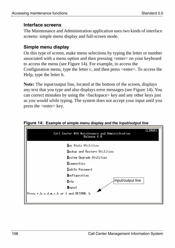
Accessing maintenance functions Standard 2.0
108 Call Center Management Information System
Interface screensThe Maintenance and Administration application uses two kinds of interface screens: simple menu display and full-screen mode.
Simple menu displayOn this type of screen, make menu selections by typing the letter or number associated with a menu option and then pressing <enter> on your keyboard to access the menu (see Figure 14). For example, to access the Configuration menu, type the letter c, and then press <enter>. To access the Help, type the letter h.
Note: The input/output line, located at the bottom of the screen, displays any text that you type and also displays error messages (see Figure 14). You can correct mistakes by using the <backspace> key and any other keys just as you would while typing. The system does not accept your input until you press the <enter> key.
Figure 14: Example of simple menu display and the input/output line
Input/output line

May 2007 Accessing maintenance functions
CC MIS Installation and Maintenance 109
Full-screen modeOn this type of screen, make menu selections using the function keys, arrow keys, and page up/down keys (see Figure 15). For example, to access the Help screen (in Figure 15), press the F4 function key.
There are two ways to select a menu item in a full-screen mode interface:
highlight the option using the up/down arrow keystype the number of the option and press the <enter> key
You can use several control commands in full-screen mode, including the following:
Ctrl-R—redraws a screen Ctrl-T—allows you to select a new terminal type
Figure 15: Example of full-screen mode (Configuration menu screen)
Function command line

Accessing maintenance functions Standard 2.0
110 Call Center Management Information System
Accessing pop-up menusVarious screens have pop-up menus associated with them, which list the available options. Access a pop-up menu by pressing its associated function key listed at the bottom of the menu screen.
Function keys, also called soft keys, operate as toggles. The key that selects the function is the same key that deselects or clears that function.
Paging through a screen or menuIn some instances, a menu can have many options from which to select. Use the following commands to move to the top or bottom of the menu or screen:
0-PgUp (or up arrow)—to page to the top of the menu or screen0-PgDn (or down arrow)—to page to the bottom of the menu or screenFor some terminal types, you use Ctrl-F and Ctrl-B to page forward and backward, respectively.
Function keys and commandsThe function keys associated with a command are listed on the lower portion of the appropriate screen. The procedures in this NTP provide the name of the function key and the screens show examples of function keys with associated commands.
Notes:
1. The actual function key depends on the type of terminal and emulation mode being used. See your program screen for the actual function key to press to select the desired command.
2. In some cases, there are too many function keys to fit on the function key line. When this occurs, a special function key labeled >> appears on the right side of the function key line. Press this function key to view the additional function keys.

May 2007 Accessing maintenance functions
CC MIS Installation and Maintenance 111
Effect of the CC MIS operating state on the menu systemThe availability of certain functions depends on the state of CC MIS. The majority of the functions are available at all times; however, some functions are available only when CC MIS is shut down, while other functions are available only when CC MIS is operating.
Partitions can be running or stopped. Stopping one partition does not affect the running status of other partitions.
The CC MIS application can be running or shut down. For the most part, the CC MIS shutdown is automatic. When you request a function that requires that you shut down CC MIS, the software prompts you to confirm the CC MIS shutdown. The confirmation gives you control over the state of CC MIS. Table 13 identifies the functions that require CC MIS to shut down and whether the shutdown is automatic.
The Maintenance and Administration interface takes into account the state of CC MIS and alters its menus accordingly. For example, the menu options on the Run State Utilities screen change with the state of the CC MIS application. An example of this changing menu option is as follows:
Startup the CC MIS Application (when CC MIS is shut down)Shutdown the CC MIS Application (when CC MIS is running)
Table 13: Functions requiring CC MIS to shut down
FunctionManual
shutdownAutomatic shutdown
Load new software version — X
Install license keycode
Note: You must manually restart CC MIS any time following the installation of a new license keycode.
X —
Change CC MIS network name in the Configuration > System Configuration screen
X —

Accessing maintenance functions Standard 2.0
112 Call Center Management Information System
Setting up a new CC MIS system (overview)
To set up a new system, proceed through the menus to access the Configuration menu. After you install the system and log on successfully, select the Configuration option from the Maintenance and Administration main menu. This causes the Configuration menu to appear. After the Configuration menu appears, proceed as follows:
Non-network
1. Configure the system.(See “Configuring the CC MIS application” on page 131.)
2. Configure the switch links.(See “Configuring the CC MIS application” on page 131.)
3. Configure disk storage.(See “Disk storage” on page 151.)
4. Configure partitions (local). (See “Local partitions” on page 197.)
Network
1. Configure the system. (See “Configuring the CC MIS application” on page 131 and “Networked CC MIS” on page 251.)
2. Configure the switch links.(See “Networked CC MIS” on page 251.)
3. Configure disk storage.(See “Disk storage” on page 151.)

May 2007 Accessing maintenance functions
CC MIS Installation and Maintenance 113
4. Configure the physical network.(See “Networked CC MIS” on page 251.)
5. Configure partitions. (See “Local partitions” on page 197 and NAPs in “Networked CC MIS” on page 251.)

Accessing maintenance functions Standard 2.0
114 Call Center Management Information System
Logging on
Log on to CC MIS Maintenance and Administration to perform the following tasks:
configure the applicationmonitor the operation of the applicationinstall software upgrades
The user ID is ccmis and the password is defined during the C MIS installation.
After a successful logon, the system displays the Call Center MIS Maintenance and Administration main menu (see Figure 16). Figure 16: Call Center MIS Maintenance and Administration main menu

May 2007 Accessing maintenance functions
CC MIS Installation and Maintenance 115
Constraints
You log on to Linux when you log on to the Maintenance and Administration interface.
Note: This is not the same as a supervisor logging on to CC MIS from a supervisor terminal.
ATTENTION Unauthorized Use of ConsoleEnsure that you log off of your session when you are not using the Maintenance and Administration interface. Anyone can change your password through the Modify Password function of the main menu. This terminal provides direct access to CC MIS configuration. Improper use of this tool can cause a system outage. Be cautious about leaving your maintenance console logged on.

Accessing maintenance functions Standard 2.0
116 Call Center Management Information System
Logging on to the Maintenance and Administration interface
Perform the steps in Procedure 4 to log on to the CC MIS Maintenance and Administration interface.Procedure 4: Logging on to the Maintenance and Administration interface
1 Verify that the system and maintenance console are on.
The system displays the following prompt:
Console Login:
2 Type ccmis at the prompt.
The system displays the following prompt:
Password:
3 Type the password.
Note: For security purposes, no characters appear as you type the password.
If the logon is successful, the system displays the Maintenance and Administration main menu (see Figure 16 on page 114).
If the logon is unsuccessful, the system displays the following message:
Login incorrect login:
Repeat Step 1 to Step 3 or contact your system administrator for the password.

May 2007 Accessing maintenance functions
CC MIS Installation and Maintenance 117
Changing your password
Your password protects access to maintenance functions. You can change the password to maintain secured access to system functions and, ultimately, to the system configuration.
Changing the ccmis password
Perform the steps in Procedure 5 to change your password.Procedure 5: Changing the ccmis password
1 On the Maintenance and Administration main menu, type m to access the Modify Password screen.
The system displays the following prompt:
Do you want to change the CC MIS maintenance password? (yes/no)
2 Enter y (for yes) to change the password or enter n (for no) to keep the existing password.
If you enter n is entered, the Maintenance and Administration main menu reappears.
If y is entered, the system displays the following prompt:
Enter a new password.
New password:
3 Enter a new password.
Note: You must enter a minimum of one character.
ATTENTION! Both the user ID (ccmis) and the password are case-sensitive. For example, the password SUPR1 is not the same as supr1.
Accessing maintenance functions Standard 2.0
118 Call Center Management Information System
The system displays the following prompt:
Re-enter new password:
4 Reenter the password to confirm your change.
The system returns to the Maintenance and Administration main menu.
Note: If you fail to confirm the new password (after three attempts), the system cancels the password change and you are directed back to the Maintenance and Administration main menu.
.
UNAUTHORIZED USE OF CONSOLE — DO NOT LEAVE YOUR CONSOLE LOGGED ON AND UNATTENDED.
Anyone with access to the console can change the password using the Modify Password function on the Maintenance and Administration main menu. The console provides direct access to the CC MIS configuration. Improper use of this tool can cause a system outage.If you log off of the maintenance console (without knowing that your password has been changed), you cannot log back on to Maintenance and Administration without obtaining the new password from the individual who changed the password.

May 2007 Accessing maintenance functions
CC MIS Installation and Maintenance 119
Logging off
Log off of the Maintenance and Administration interface after you complete your work. Never leave the console unattended and logged on. Logging off protects the system configuration.
Logging off of the ccmis account and CC MIS Maintenance and Administration interface
Perform the steps in Procedure 6 to log off of the CC MIS Maintenance and Administration interface.Procedure 6: Logging off of the ccmis account and CC MIS Maintenance and Administration interface
On the Maintenance and Administration main menu, press l to log off of the Maintenance and Administration main menu.
The system returns to the following prompt:
Console Login:

Accessing maintenance functions Standard 2.0
120 Call Center Management Information System
Maintenance and Administration menus and screens
This section outlines the menus and screens available in the CC MIS Maintenance and Administration interface.
Call Center MIS Maintenance and Administration main menu
The main menu for the Call Center MIS Maintenance and Administration interface (see Figure 17) appears when you log on to CC MIS.
To access a menu option on the main menu, type the letter (r, b, s, d, m, c, h, or l) associated with the option, and then press <enter>.Figure 17: Maintenance and Administration main menu

May 2007 Accessing maintenance functions
CC MIS Installation and Maintenance 121
Run State Utilities menu
Type the letter r on the main menu to access the Run State Utilities menu (see Figure 18).
The Run State Utilities menu provides access to commands used for startup and shutdown of the CC MIS application and individual partitions. You can reboot or power down the CC MIS server. The menu also contains the Update Switch Configuration Data command.Figure 18: Run State Utilities menu

Accessing maintenance functions Standard 2.0
122 Call Center Management Information System
Backup and Restore Utilities menu
Type the letter b on the main menu to access the Backup and Restore Utilities menu (see Figure 19).
The backup and restore menu provides access to commands used to do the following:
Backup customer data. Restore data in the event of data corruption.Import selected CC MIS databases from other CC MIS systems over a TCP/IP connection. CC MIS Release 6.0 systems can import data from CC MIS systems running 5.2 or later.
Figure 19: Backup and Restore Utilities menu

May 2007 Accessing maintenance functions
CC MIS Installation and Maintenance 123
System Upgrade Utilities menu
Type the letter s on the main menu to access the System Upgrade Utilities menu (see Figure 20).
The System Upgrade Utilities menu provides access to commands used for loading new software versions, displaying license information, and installing license keycodes.Figure 20: System Upgrade Utilities menu

Accessing maintenance functions Standard 2.0
124 Call Center Management Information System
Diagnostics menu
Type the letter d on the main menu to access the Diagnostics menu (see Figure 21).
The Diagnostics menu provides access to diagnostic programs for CC MIS such as logs, the system monitor, and tracing switch links. Figure 21: Diagnostics menu

May 2007 Accessing maintenance functions
CC MIS Installation and Maintenance 125
Modify Password screen
Type the letter m on the main menu to access the Modify Password screen (see Figure 22).
You can change the password for the ccmis user ID on this screen. For details about changing the user ID, see Procedure 5 on page 117.Figure 22: Modify Password screen

Accessing maintenance functions Standard 2.0
126 Call Center Management Information System
Configuration menu
Type the letter c on the main menu to access the Configuration menu (see Figure 23).
The Configuration menu operates in two modes: Display Only and Updates Allowed. The Configuration menu starts in Display Only mode. If you need to make a change, use the Get Update Access Rights option to change to Updates Allowed mode.
Use the Configuration menu to configure the CC MIS application, including setting up switch links, adding or deleting partitions, and changing disk storage parameters.Figure 23: Configuration menu

May 2007 Accessing maintenance functions
CC MIS Installation and Maintenance 127
Help
You can access the online Help (see Figure 24) from the main menu by typing the letter h. The online Help is also available from all of the Maintenance and Administration menus. Figure 24: Sample online Help screen
The system displays the help information that is available for the current menu or screen. That is, the information available from the Help menu changes depending on the menu or screen from which you access the Help. When the Help system is displayed on your console, the Maintenance and Administration menus and functions are not available.
The procedure for accessing the online Help depends on the type of screen from which you are navigating:
To access the online Help from a simple display menu screen, see Procedure 7 on page 128.To access the online Help from full-screen mode, see Procedure 8 on page 129.

Accessing maintenance functions Standard 2.0
128 Call Center Management Information System
Accessing Help from simple display menusPerform the steps in Procedure 7 to access the Help facility from simple display menus.
Procedure 7: Accessing online Help in maintenance menus (from simple menu display screens)
1 Type h (Help) to access the online Help, and then press <enter>.
The system displays Help information for the menu options on the current page (see Figure 24 on page 127).
Note: To access the online Help from the Maintenance interface when it is in full-screen mode, see Procedure 8 on page 129.
2 Press the space bar or <enter> key to scroll through the online Help text.
3 To go back to the previous page, type -1 and press <enter>.
Note: The Help screens for menu windows are presented on-screen using the UNIX more command. (The more command is transparent to the user). Type h to view a list of possible more commands. Press <enter> to exit this list and return to the Help text.
4 Type q (Quit) to exit the online Help.

May 2007 Accessing maintenance functions
CC MIS Installation and Maintenance 129
Accessing Help from full-screen modePerform the steps in Procedure 8 to access the online Help from full-screen mode.
When the interface is in full-screen mode, you access the online Help by using the Help function key. The Help command is located in the lower portion of the screen. The Help function key can appear as <Help>=Help, f9=Help, or another designated function key xx=Help.
For example, the Configuration screen is a full-screen display (see Figure 15 on page 109). Procedure 8: Accessing the online Help from full-screen mode
1 Press the <Help> key (or appropriate function key) to access the Help screen.
2 Depending on your terminal type, use one of the following methods to scroll through the help text.
Prev Scrn - Returns to the previous screen.Next Scrn - Moves to the next screen.
OR
Page Up - Returns to the previous screen.Page Down - Moves to the next screen
OR
Up arrow - Scrolls up one line.Down arrow - Scrolls down one line.
Note: The available key names depend on terminal type.
3 Press the Help function key again to exit the online Help.
Logoff
To log off of the CC MIS Maintenance and Administration application, press the letter l on the main menu.

Accessing maintenance functions Standard 2.0
130 Call Center Management Information System

CC MIS Installation and Maintenance 131
C h a p t e r 7
Configuring the CC MIS application
In this chapterIntroduction . . . . . . . . . . . . . . . . . . . . . . . . . . . . . . . . . . . . . . . . . . . . . . 132
Accessing the Configuration main menu. . . . . . . . . . . . . . . . . . . . . . . . 133
System configuration. . . . . . . . . . . . . . . . . . . . . . . . . . . . . . . . . . . . . . . 135
Switch link configuration . . . . . . . . . . . . . . . . . . . . . . . . . . . . . . . . . . . . 140
Terminal server configuration . . . . . . . . . . . . . . . . . . . . . . . . . . . . . . . . 148
Disk storage . . . . . . . . . . . . . . . . . . . . . . . . . . . . . . . . . . . . . . . . . . . . . 151
SNMP configuration . . . . . . . . . . . . . . . . . . . . . . . . . . . . . . . . . . . . . . . 154
System configuration reports . . . . . . . . . . . . . . . . . . . . . . . . . . . . . . . . 157

Configuring the CC MIS application Standard 2.0
132 Call Center Management Information System
Introduction
Through the Configuration main menu (see Figure 25 on page 134), you can access submenus where you can define or alter parameters related to CC MIS system configuration.
The usual sequence of steps for configuring a CC MIS system are as follows:
1. System Configuration—Specify the system name, the CC MIS network name, and the backup directory.
2. Switch Link Configuration—Select the link type and specify link information.
3. Terminal Server Configuration—Specify local area network (LAN)-based terminal servers available for CC MIS.
4. Disk Storage—If needed, specify additional storage directories.
5. Partition Configuration—Add a partition, and then specify the following:
Connection ParametersPartition OptionsDisk AllocationStorage CalculatorSerial TerminalsStatic LAN TerminalsWallboardsMaster Privilege Definition

May 2007 Configuring the CC MIS application
CC MIS Installation and Maintenance 133
Accessing the Configuration main menu
You access all configuration functions from the Configuration main menu.
Perform the steps in Procedure 9 to access the Configuration main menu.Procedure 9: Accessing the Configuration main menu and switching between Display Only and Updates Allowed modes
1 Access the Maintenance and Administration main menu.
2 Type c to access the Configuration main menu.
The system displays the Configuration main menu (see Figure 25 on page 134) in Display Only mode (see Figure 25 on page 134).
Note: The Physical Network Configuration option is displayed only on a networked node.
3 To make changes in the Configuration main menu, select the Get Update Access Rights option to switch from Display Only mode to Updates Allowed mode.
The Configuration screen and menu changes (see Figure 26). The screen is now in Updates Allowed mode and option 2 changed to Release Update Access Rights.
Note: Updates Allowed mode uses a 2-minute inactivity timer. If the timer expires, you are removed from the Configuration screen and returned to the Maintenance and Administration main menu.

Configuring the CC MIS application Standard 2.0
134 Call Center Management Information System
Figure 25: Configuration menu (in Display Only mode)
Figure 26: Configuration menu (in Updates Allowed mode)

May 2007 Configuring the CC MIS application
CC MIS Installation and Maintenance 135
System configuration
The System Configuration screen contains system-wide data. This is the first screen you use when setting up a new system. Information contained in this screen includes the system name, CC MIS network name (if networking is enabled), and the backup directory.
Note: You must shut down the system to change the CC MIS network name.
Perform the steps in Procedure 10 to access the System Configuration screen.Procedure 10: Accessing the System Configuration screen
1 Access the Maintenance and Administration main menu.
2 Type c to access the Configuration main menu.
The system displays the Configuration main menu in Display Only mode.
3 Select Get Access Updates Rights to switch to Updates Allowed mode.
4 Select System Configuration.
The System Configuration screen appears (see Figure 27 on page 136).

Configuring the CC MIS application Standard 2.0
136 Call Center Management Information System
Figure 27: System Configuration screen
Field descriptions
Table 14 describes the System Configuration screen fields.Table 14: System Configuration field descriptions (Part 1 of 2)
Field Description
System Name The System Name field specifies the name of the CC MIS system that appears at the top of each Configuration Report.This name can be up to 16 characters in length. Only uppercase and lowercase letters (a-z, A-Z) and numbers (0-9) can be used.

May 2007 Configuring the CC MIS application
CC MIS Installation and Maintenance 137
CC MIS Network Name The CC MIS Network Name field appears only if you purchased the networking option. The Network Name is used for messaging among nodes in the CC MIS Physical Network. All nodes in a network must have the same CC MIS Network Name. You can edit this field only when the system is down. Only uppercase and lowercase letters (a-z, A-Z) and numbers (0-9) can be used.
Backup Directory The Backup Directory field specifies the directory in which CC MIS backs up its databases. The directory provided must be an existing directory with write permission for the CC MIS application. The length of the directory name is restricted to a maximum of 50 characters.If the Backup Directory field is left empty, nightly/automatic backups do not occur and you cannot perform ad hoc/manual backups.
Table 14: System Configuration field descriptions (Part 2 of 2)
Field Description

Configuring the CC MIS application Standard 2.0
138 Call Center Management Information System
Port Allocation
The Port Allocation screen provides a system-wide view of serial ports allocated on the system (serial ports are provided through terminal servers) and identifies the partition to which they are allocated.
To change the port allocations, you must press the Port Configuration function key listed at the bottom of the System Configuration screen (Configuration > System Configuration > Port Allocation).
Serial ports are allocated on the Serial Terminal screen. Access this screen using the Partition Configuration > Configuration Options > Serial Terminals option. For more information, see “Serial terminals” on page 231.Wallboard ports are allocated on the Wallboards screen. Access this screen using the Partition Configuration > Configuration Options > Wallboards option. For more information, see “Wallboards” on page 233.
Perform the steps in Procedure 11 to view the Port Allocation screen.Procedure 11: Accessing the Port Allocation screen
1 Access the Maintenance and Administration main menu.
2 Type c to access the Configuration main menu.
The system displays the Configuration main menu in Display Only mode.
3 Select System Configuration to access the System Configuration screen.
The System Configuration screen appears (see Figure 27 on page 136).
4 Press the Port Allocation function key listed at the bottom of the System Configuration screen.
The Port Allocation screen appears (see Figure 28 on page 139).
Note: The Port Allocation screen is a Display Only screen (even when in Updates Allowed mode).

May 2007 Configuring the CC MIS application
CC MIS Installation and Maintenance 139
Figure 28: Port Allocation screen
5 When you finish viewing the Port Allocation screen, press the Exit function key to return to the main menu.

Configuring the CC MIS application Standard 2.0
140 Call Center Management Information System
Switch link configuration
The CC MIS server connects to the DMS-ACD in one of two ways:
direct IP connectionTCP/IP bridge device (bridge between an IP connection from the CC MIS server to an X.25 connection to the switch)
For more information about TCP/IP bridge devices, see Appendix B, “TCP/X.25 bridge devices.”
After you establish a connection between the server and the switch, you can configure the switch links on the CC MIS server.
You can create multiple link definitions using the Switch Link Configuration screen. There are two types of links:
Live TCP/IP links (see page 143)Simulator links (see page 147)
This function provides a means of defining logical links that can be used by a partition. The number of link definitions that you can define on a system depends on the license keycode.
Perform the steps in Procedure 12 to access the Switch Link Configuration screen.Procedure 12: Accessing the Switch Link Configuration screen
1 Access the Maintenance and Administration main menu.
2 Type c to access the Configuration main menu.
The system displays the Configuration main menu (see Figure 25 on page 134).
3 Select Get Access Updates Rights to switch to Updates Allowed mode.
4 Select Switch Link Configuration.

May 2007 Configuring the CC MIS application
CC MIS Installation and Maintenance 141
The Switch Link Configuration screen appears (see Figure 29 on page 141).
Link Number—Displays the link number assigned to the link that you are defining. This number is assigned when the link is saved.
Link Type—Indicates whether the link is a Live TCP/IP link or a Simulator link. A live link is used in either precut or product mode to connect to an ACD switch. A Simulator link is used in either training or precut mode to run the internal switch simulator to simulate call traffic for training purposes.
Figure 29: Switch Link Configuration screen—initial
5 Press the Options function key.
A menu offers the choice of Simulator or Live TCP/IP link (see Figure 30).

Configuring the CC MIS application Standard 2.0
142 Call Center Management Information System
Figure 30: Switch Link Configuration — Simulator or Live TCP/IP pop-up menu
6 Select the link type:
If you select Simulator as the link type, see “Simulator link” on page 147 for more information.
If you select Live TCP/IP as the link type, see “Live TCP/IP link” on page 143 for more information.
Commands menu
The Switch Link Configuration screen has the following commands available in the Commands menu:
ExitClear the formRead an existing link definitionSave link definitionDelete an existing link definition

May 2007 Configuring the CC MIS application
CC MIS Installation and Maintenance 143
Live TCP/IP link
If you select Live TCP/IP as the link type from the Options command function key, the remainder of the fields are displayed on the screen. The Switch Link Configuration screen for a Live TCP/IP link appears as shown in Figure 31. For more information about this screen, see “Live TCP/IP link fields” on page 144.Figure 31: Switch Link Configuration screen - Live TCP/IP link
You specify the Live TCP/IP link definitions to obtain a live connection to the DMS/MSL-100.
ACD data linkFor CC MIS to communicate with the DMS-ACD, the CC MIS must establish datalink connections with the DMS-ACD over which agent and call event messages can pass. An ACD data link is associated with only one ACD pool.

Configuring the CC MIS application Standard 2.0
144 Call Center Management Information System
To successfully connect to the switch, you must obtain certain information from the DMS-ACD and use it to complete the fields in the switch link definition. This information is as follows:
The user ID and password used to log on to the switch.The ACD pool name and password to associate with this link (from the ACDMISPL table on the switch).The ACD subpool names and passwords for this ACD pool (from the ACDMISSP table on the switch). Note: The subpool information is not required in the switch link definition, but it is required when defining the “Connection Parameters” for partitions using this switch link (see “Connection parameters” on page 229).
Live TCP/IP link fieldsTable 15 describes some of the fields on the Live TCP/IP Link screen.Table 15: Fields on the Live TCP/IP Link screen (Part 1 of 3)
Field Description
Link Number Displays the link number assigned to the link that is being defined. The link number is assigned when the link is saved.
Link Type Indicates that the link is a Live TCP/IP link. A live link is used in either precut or product mode to connect to an ACD switch.
Enabled Used to enable or disable the link. The default is Enabled.
ACD User ID and ACD User Password
The user ID and password used to log on to the switch.
ACD Pool Name and ACD Pool Password
The name and password of the ACD pool to associate with this switch link. This can be found in ACDMISPL table on the switch.

May 2007 Configuring the CC MIS application
CC MIS Installation and Maintenance 145
Reinit Time Specifies a time (in 24-hour format) at which the system requests reinitialization from the switch. Reinitialization automatically picks up any additions or deletions made to the switch datafill (such as new or deleted positions, groups or subgroups). The reinitialization time must be during off hours and preferably after the CC MIS midnight processing is completem, for example, 2:00 a.m.Leave this field blank when no daily reinitialization is required.
Synchronize to Switch Time and Timezone Adjustment
Used to set the time for the system and to adjust time zone differences.
Note: Partitions on a single node can have different time zones than the rest of the system. Use the Partition Options screen to set this feature.
Note: Any time zone adjustments for the link must be relative to the base time zone set for the server (and not to any of the partitions).
Switch Code Allows three additional digits to be prepended to all directory numbers (DNs) received from the switch. This field is normally left blank. However, you must specify this field if the CC MIS networking feature is used in a private network where duplicate DNs that appear on more than one switch are used. Using a unique switch code for each switch in the private network, CC MIS can make the duplicated DNs unique, thereby allowing the CC MIS networking feature to operate properly.
Table 15: Fields on the Live TCP/IP Link screen (Part 2 of 3)
Field Description

Configuring the CC MIS application Standard 2.0
146 Call Center Management Information System
For additional information, see “Switch link datafill requirements” on page 333.
Primary Link Specifies the IP address and port number to connect to for this link.
Secondary link Specifies a second IP address and port number to use to connect to the switch in the event that a connection cannot be established using the primary IP address and port number.This field is available only if the link redundancy option is enabled by the license keycode. You can leave this field blank if link redundancy is not required for this live link definition.
Table 15: Fields on the Live TCP/IP Link screen (Part 3 of 3)
Field Description

May 2007 Configuring the CC MIS application
CC MIS Installation and Maintenance 147
Simulator link
If you choose Simulator as the link type, the Enabled and Simulator Configuration fields appear on the screen. Figure 32 shows the Switch Link Configuration screen for a Simulator link.Figure 32: Switch Link Configuration screen - Simulator link
You specify Simulator link definitions to set aside a link number to specify that a partition should connect to the simulator.
Note: The configuration information is explained in the online Help. Press the Help function key to view the Help text for this screen.

Configuring the CC MIS application Standard 2.0
148 Call Center Management Information System
Terminal server configuration
You can use the Terminal Server Configuration screen (see Figure 33) to specify LAN-based terminal servers that are available for CC MIS. Figure 33: Terminal Server Configuration screen
Perform the steps in Procedure 13 to add and configure a terminal server.Procedure 13: Adding and configuring a terminal server
1 Access the Maintenance and Administration main menu.
2 Type c to access the Configuration main menu.
The system displays the Configuration main menu (see Figure 25 on page 134).
3 Select Get Access Updates Rights to switch to Updates Allowed mode.
4 Select Terminal Server Configuration.
The Terminal Server Configuration screen appears (see Figure 34 on page 149).
5 To add a new terminal server, press the Add function key.

May 2007 Configuring the CC MIS application
CC MIS Installation and Maintenance 149
A dialog box appears on the screen in which you can enter the IP address for the terminal server (see Figure 34).
Figure 34: Adding a terminal server
6 Enter the IP address of the terminal server.
7 Change the Base TCP Port from 8000 (the default) to 8001.
8 To configure a terminal server, press the Configure function key.
The screen shown in Figure 35 appears. Follow the instructions on the screen to enter and configure the terminal server.

Configuring the CC MIS application Standard 2.0
150 Call Center Management Information System
Figure 35: Configuring a terminal server
When the configuration is complete, the Terminal Server Configuration screen reappears.
9 To edit the fields of a terminal server listed on the Terminal Server Configuration screen, first navigate to the field, and then press the Edit Field function key (see Figure 36 on page 150).
Figure 36: Editing a field on the Terminal Server Configuration screen

May 2007 Configuring the CC MIS application
CC MIS Installation and Maintenance 151
Disk storage
The Disk Storage screen is a system-wide configuration option that can be required before creating partitions. The installation script creates an initial entry in the Disk Storage screen for the storage of partition data; however, as the system grows you can add additional file systems to provide space for new partitions.
On the Disk Storage screen, you can assign disks to partitions, view disk usage statistics, alter size limits of partitions, and move partitions between disks.
Perform the steps in Procedure 14 to access the Disk Storage screen.Procedure 14: Accessing the Disk Storage screen
1 Access the Maintenance and Administration main menu.
2 Type c to access the Configuration main menu.
The system displays the Configuration main menu (see Figure 25 on page 134).
3 Select Get Access Updates Rights to switch to Updates Allowed mode.
4 Select Disk Storage.
The Disk Storage screen appears (see Figure 37 on page 152).

Configuring the CC MIS application Standard 2.0
152 Call Center Management Information System
Figure 37: Disk Storage
5 Press the Disk Usage Section function key.
The screen focus shifts to the Disk Usage Statistics area in the lower portion of the screen (see Figure 38) and the function keys change.
Figure 38: Disk Usage Statistics

May 2007 Configuring the CC MIS application
CC MIS Installation and Maintenance 153
6 To add another file system, press the Add function key.
The Add Disk Storage menu appears (see Figure 39).
Figure 39: Add Disk Storage
7 Enter the Directory where this physical device is mounted.
Note: Leave the Disk Size field as 0 MB, as this allocates all of the disk space for CC MIS storage. To limit the amount of disk space used by the CC MIS application, specify the space limitation (in megabytes).
8 Press the Commands function key.
9 Press the Submit function key to save the new directory.

Configuring the CC MIS application Standard 2.0
154 Call Center Management Information System
SNMP configuration
With the Simple Network Management Protocol (SNMP) feature, an SNMP-based network management system (NMS) can monitor both the CC MIS system and the ACD call center operation.
Notes:
1. The optional SNMP feature is enabled by the license keycode. If the feature is not enabled, this screen is not available on the system.
2. CC MIS only supports Version 1 of the SNMP protocol.
You can use the SNMP Configuration screen to set up three communities and to specify addresses of SNMP managers. The configuration defined through this screen allows access to the system-wide SNMP information provided by CC MIS, including the standard MIB-2.
You enable the SNMP feature for a partition through the Partition Configuration menu by accessing the Partition Options screen for a selected partition (see “Local partitions” on page 197).
The SNMP feature has a reporting option that you can use to print a system report for SNMP configuration (see “SNMP Configuration report” on page 449). You can access this option through the Reports command on the Configuration main menu.
ATTENTION! Due to the technical nature of the SNMP feature, Nortel recommends that administrators and users of this feature have a background in network management and the SNMP protocol.
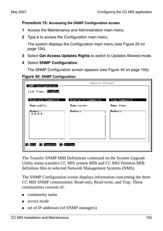
May 2007 Configuring the CC MIS application
CC MIS Installation and Maintenance 155
Procedure 15: Accessing the SNMP Configuration screen
1 Access the Maintenance and Administration main menu.
2 Type c to access the Configuration main menu.
The system displays the Configuration main menu (see Figure 25 on page 134).
3 Select Get Access Updates Rights to switch to Updates Allowed mode.
4 Select SNMP Configuration.
The SNMP Configuration screen appears (see Figure 40 on page 155).
Figure 40: SNMP Configuration
The Transfer SNMP MIB Definitions command on the System Upgrade Utility menu transfers CC MIS system MIB and CC MIS Partition MIB definition files to selected Network Management Systems (NMS).
The SNMP Configuration screen displays information concerning the three CC MIS SNMP communities: Read-only, Read-write, and Trap. These communities consists of:
community nameaccess modeset of IP addresses (of SNMP managers)

Configuring the CC MIS application Standard 2.0
156 Call Center Management Information System
Use the SNMP Configuration screen to define Network Management Systems (NMS) that can access to the system-wide information defined by the Management Information Bases (MIBs). The two types of MIBs are:
CC MIS system MIBMIB-2 (standard MIB)
Field descriptionsTable 16 describes theSNMP Configuration screen fields. Table 16: SNMP field descriptions
Field Description
Community The communities are as follows:Read-only—Lists the IP addresses of SNMP managers that can query MIB variables.Read-write—Lists the IP addresses of SNMP managers that can both query and set MIB variables.Trap—Lists the IP addresses of SNMP managers that receive traps generated by the system MIBs.
Name This name can be 1 to 15 characters in length. You can use any character except the vertical bar. Nortel recommends that you do not use the same name for the Read-only and Read-write communities. When they both have the same name, the Read-write community member list is searched first.
Members This area lists the IP addresses of SNMP managers that have access to the community. An entry of 0.0.0.0 indicates that all SNMP managers are considered part of that community.
Note: The 0.0.0.0 value cannot be used in the Trap community because CC MIS needs an explicit list of IP addresses to which traps are sent.

May 2007 Configuring the CC MIS application
CC MIS Installation and Maintenance 157
System configuration reports
System configuration reports provide a record of system configuration changes and setup. Select the Reports option from the Configuration menu to access system configuration reports. Procedure 16: Accessing reports
1 Access the Maintenance and Administration main menu.
2 Type c to access the Configuration main menu.
The system displays the Configuration main menu (see Figure 25 on page 134).
3 Select Reports.
The Report menu appears (see Figure 41).
4 Press the Options function key to display a list of available reports.
Figure 41: Configuration Reports
5 Type the number associated with the report you want to view.
Note: A system default printer must be defined to print system configuration reports directly from the CC MIS server.

Configuring the CC MIS application Standard 2.0
158 Call Center Management Information System
The following system configuration reports are available:
System Configuration Report
Port Allocation Report
Switch Link Configuration Report
Terminal Server Configuration Report
Partition Configuration Report
Disk Allocation Report
Connection Parameters Report
Partition Options Report
Static LAN Terminals Configuration Report
Serial Terminals Configuration Report
Wallboard Configuration Report
Storage Parameters Report
Interval Configuration Report (available only if you purchase the Flexible Intervals option)
Simulator Configuration Report
SNMP Configuration Report(available only if you purchase the SNMP Support option)
Physical Network Configuration Report(available only if you purchase the Networking option)
Virtual Network Configuration Report(available only if you purchase the Networking option)
Master Privilege Override
Master Privilege Definition
All Reports
Note: For examples of these reports, see “System Configuration reports” on page 431.
6 Navigate to the Destination field and press the Options function key.

May 2007 Configuring the CC MIS application
CC MIS Installation and Maintenance 159
7 Select one of the following destinations for the report.
System Default Printer—This option sends the report directly from the CC MIS server to the system default printer. Go to Step 9.
Partition—If you select this option, you can select a partition defined on the system and then select any one of the report destinations defined within that partition. If you send the report to a partition device, two additional fields appear on the screen (Partition and Send To), in which you can select the partition and the device within that partition. Go to Step 8.
Figure 42: Destination options

Configuring the CC MIS application Standard 2.0
160 Call Center Management Information System
8 If you selected Partition in Step 7, do the following:
a. Press the Options function key to display a list of available partitions and then select the partition.
b. Navigate to the Send To field and press the Options function key to display a list of defined output devices. These devices can be one of three possible types: Printer, File, or Email.
c. Select the output device.
If you select a File device, the File Name field appears where you can enter the name of a file in which to save the report. Nortel recommends that you use a .txt file extension. If you do not enter a file name in this field, the default file name as specified in the Client Services Setup on that PC is used.
If you select an Email device, the Email Addr field appears. Enter the e-mail address (in the form <user>@<host>) of the recipient receiving the report.
9 Press the Commands function key, and then select the Generate option to generate the report.

CC MIS Installation and Maintenance 161
C h a p t e r 8
Shutdown, startup, reboot, and power down
In this chapterIntroduction . . . . . . . . . . . . . . . . . . . . . . . . . . . . . . . . . . . . . . . . . . . . . . 162
Shut down the CC MIS application . . . . . . . . . . . . . . . . . . . . . . . . . . . . 164
Start up the CC MIS application . . . . . . . . . . . . . . . . . . . . . . . . . . . . . . 166
Power down the system . . . . . . . . . . . . . . . . . . . . . . . . . . . . . . . . . . . . 168
Power up the system. . . . . . . . . . . . . . . . . . . . . . . . . . . . . . . . . . . . . . . 170
Reboot the system . . . . . . . . . . . . . . . . . . . . . . . . . . . . . . . . . . . . . . . . 172

Shutdown, startup, reboot, and power down Standard 2.0
162 Call Center Management Information System
Introduction
This chapter contains procedures for the shut down, start up, reboot, and power down CC MIS commands and functionality. These commands are available from the Run State Utilities menu (see Figure 43). Figure 43: Run State Utilities menu
Update Switch Configuration Data command
For information about this menu command, see “Switch configuration data updates” on page 323.
Partition Startup and Shutdown command
You start up and shut down CC MIS from the Run State Utilities menu. You can also perform these tasks from the Partition Configuration screen (see “Local partitions” on page 197).

May 2007 Shutdown, startup, reboot, and power down
CC MIS Installation and Maintenance 163
Shutdown/Startup of the CC MIS Application command
You must shut down CC MIS shutdown before you can perform certain functions through the maintenance console.
Note: CC MIS is automatically shut down for functions requiring shutdown.
The shutdown command leaves the operating system and other non-CC MIS software running. For more details, see “Shut down the CC MIS application” on page 164.
After you shut down CC MIS, you must start up the CC MIS application. For more details, see “Start up the CC MIS application” on page 166.
Power Down/Up the System
The Power Down the System command removes power from CC MIS server. You select the power down command from the Run State Utilities menu.
The Power Up the System command returns power to the CC MIS server.
Note: After you power down the system, use the power button to power up the CC MIS server.
For more details, see “Power down the system” on page 168 and “Power up the system” on page 170.
Reboot the System
The Reboot the System command allows support personnel to remotely reboot the system without on-site intervention. That is, a local person at the remote site is not required to reboot the system.
For more details, see “Reboot the system” on page 172.
Shutdown, startup, reboot, and power down Standard 2.0
164 Call Center Management Information System
Shut down the CC MIS application
The Shutdown the CC MIS Application command shuts down the CC MIS application, leaving the operating system, non-CC MIS programs, and CC MIS maintenance software running.
Note: To shut down both the CC MIS software and the Linux operating system, use the Power Down the System command.
If you request a maintenance function that can only be performed with CC MIS shut down, the maintenance and administration software automatically shuts down CC MIS. You do not need to shut down the system manually.
An exception is when you change the the Network Name, which requires manual shutdown.
Perform the steps in Procedure 17 on page 165 to manually shut down CC MIS.
ATTENTION Advise supervisors that you are shutting down the CC MIS application. Supervisors do not have access to CC MIS after you shut down the system. CC MIS supervisors are automatically logged off if you shut down the CC MIS system.

May 2007 Shutdown, startup, reboot, and power down
CC MIS Installation and Maintenance 165
Procedure 17: Manually shutting down the CC MIS application
1 Ensure that CC MIS is operating (that is, the application is running).
2 Access the Maintenance and Administration main menu.
3 Type r to display the Run State Utilities menu.
4 From the Run State Utilities menu, type s to shut down the CC MIS application.
The following warning message appears:
WARNING!Proceeding with this operation will bring down all CC MIS software.
Ready? (yes/quit)
5 Type y to proceed with the shutdown.
Note: To cancel the shutdown and return to the Run State Utilities menu, type q.
If you select y, the system displays the following message:
CC MIS terminating. . .CC MIS has been shutdown.Use the Startup the CC MIS Application command to restart it.Press RETURN to continue.
6 Press <enter>.
The Run State Utilities menu appears.
Note: Because the CC MIS application is shut down, the Run State Utilities menu changes to include the Startup the CC MIS Application option (instead of the Shutdown the CC MIS Application option).

Shutdown, startup, reboot, and power down Standard 2.0
166 Call Center Management Information System
Start up the CC MIS application
The Startup the CC MIS Application command starts up CC MIS after it is shut down (not powered down).
Perform the steps in Procedure 18 to start up the CC MIS application. Procedure 18: Starting up the CC MIS application
1 Access the Maintenance and Administration main menu.
2 Type r to display the Run State Utilities menu.
3 Type s to start up the CC MIS application.
Note: The CC MIS application must be shut down for the Startup the CC MIS Application command to appear in the Run State Utilities menu.
The system displays the following messages:
Start the CC MIS systemIs the date and time [date and time] correct? (yes/no/quit)
Note: To cancel the startup of the CC MIS application and return to the Run State Utilities menu, type q.
4 If the date and time are correct, skip to Step 6. If the time and date are incorrect, type n.
The system displays the following prompt:
Enter the correct time and date [mmddHHMMyy]:
5 Enter the correct time and date in the mmddHHMMyy format and press the <enter> key.
The system displays the following message again:
Is the date and time [date and time] correct? (yes/no/quit)
Note: You specify the time and date for the system at this prompt. The date and time are not read from the switch unless the link is

May 2007 Shutdown, startup, reboot, and power down
CC MIS Installation and Maintenance 167
synchronized with the switch. If the system experiences drifting time, you must shut down and restart it and reset the date and time.
6 Enter y to indicate that the date and time are correctly set.
The system displays the following messages:
Starting CC MIS. . . .
CC MIS has been started.
Press RETURN to continue.
7 Press <enter>.
The system displays the Run State Utilities menu. Because the CC MIS application is started, the Run State Utilities menu changes to include the Shutdown the CC MIS Application command (instead of the Startup the CC MIS Application command).

Shutdown, startup, reboot, and power down Standard 2.0
168 Call Center Management Information System
Power down the system
The Power Down the System command powers down both the CC MIS application and the Linux operating system. Power down the CC MIS server when you want to do one of the following:
stop all software that is running on the server remove power from the system to service hardware or move the system
Perform the steps in Procedure 19 to power down CC MIS. Procedure 19: Powering down the CC MIS system
1 Access the Maintenance and Administration main menu.
2 Type r to display the Run State Utilities menu.
3 Type d to power down the system.
This command powers down both the CC MIS system and the Linux operating system. The system displays the following warning messages:
Prepare the system for powering down.
This command shuts down the CC MIS system (if it is currently running), then shuts down the operating system in preparation for removing power from the system.
Ready (yes/quit)?

May 2007 Shutdown, startup, reboot, and power down
CC MIS Installation and Maintenance 169
4 Type y to power down the system.
Note: To quit and return to the Run State Utilities menu, type q.
The ccmis user is logged off as the operating system takes over the process of shutting down the system.
If you are remotely logged on when the power down command was issued, the following messages appear.
If you are logged on to the system console, the operating system displays several additional messages on the console as it stops all running services and processes.
The system displays the following messages:
CC MIS terminating ...
Beginning operating system shutdown.
SHUTDOWN startedTues Feb6 14:11:40 CDT 2005
THE SYSTEM IS BEING SHUT DOWN NOW ! ! !
Log off now or risk your files being damaged.
Power down.
5 Turn off the system power using the power button on the front of the server after the message “Power down.” appears.
6 If you powered down the system to perform a hardware maintenance operation, Nortel recommends that you unplug the power cord from the wall outlet or UPS.
.
CAUTION
Risk of corrupted filesAfter you complete Step 4, you must wait for the message “Power down” before you proceed to Step 5.
Failure to wait can result in corrupted files on the disk.

Shutdown, startup, reboot, and power down Standard 2.0
170 Call Center Management Information System
Power up the system
Use the following procedure to power up the CC MIS system, including the CC MIS application, after it is powered down using the Power Down the System command.
Note: Perform only Step 1 if the CC MIS application was running prior to the system being powered down. Perform all of the steps if the CC MIS application was shut down prior to the system being powered down.
Procedure 20: Powering up the CC MIS system
1 Turn on power using the power button on the server.
Note: System startup can take several minutes.
After the system startup is complete, the system displays the following prompt:
Console login:
2 Type ccmis.
The system displays the password prompt:
Password:
3 Type the password.
The Maintenance and Administration main menu appears.
4 Type r to select the Run State Utilities option.
The Run State Utilities menu appears.

May 2007 Shutdown, startup, reboot, and power down
CC MIS Installation and Maintenance 171
5 Type s to start up the CC MIS application.
The system displays the following messages:
Start the CC MIS systemTime:Date:Ready? (yes/quit)
6 Type y.
Note: To cancel the startup and return to the Run State Utilities Menu, type q.
The system displays the following messages:
Starting CC MIS. . . .CC MIS has been started. Press RETURN to continue.
7 Press <enter>.
The system displays the Run State Utilities menu. Because the CC MIS application is started, the Run State Utilities menu changes to include the Shut Down the CC MIS Application command (instead of the Startup the CC MIS application command).

Shutdown, startup, reboot, and power down Standard 2.0
172 Call Center Management Information System
Reboot the system
The Reboot the System command allows support personnel to remotely reboot the system without on-site intervention. That is, a local person at the remote site is not required to reboot the system.
Perform the steps in Procedure 21 to reboot the system.Procedure 21: Rebooting the system
1 Access the Maintenance and Administration main menu.
2 Type r to display the Run State Utilities menu.
3 Enter r to reboot the system.
The system displays the following warning messages:
Shutdown the system and restart
This command shuts down the CC MIS application (if it is currently running), then shuts down and restarts the operating system.
Ready? (yes/quit)
4 Type y to reboot the system.
Note: To quit and return to the Run State Utilities menu, type q.
The system displays the following messages:
Broadcast message from root (pts/0) (Tue Mar 1 08:07:58 2005):
The system is going down for reboot NOW!
System reboot requested. You will now be logged out.
Press RETURN to continue.
5 Press <enter>.
The Maintenance and Administration interface is logged off.

May 2007 Shutdown, startup, reboot, and power down
CC MIS Installation and Maintenance 173
6 After the system reboots, you can reconnect and log back on to the Maintenance and Administration interface (see Procedure 4 on page 116).

Shutdown, startup, reboot, and power down Standard 2.0
174 Call Center Management Information System

CC MIS Installation and Maintenance 175
C h a p t e r 9
Backing up, restoring, and importing data
In this chapterIntroduction . . . . . . . . . . . . . . . . . . . . . . . . . . . . . . . . . . . . . . . . . . . . . . 176
Backup directory . . . . . . . . . . . . . . . . . . . . . . . . . . . . . . . . . . . . . . . . . . 178
Backing up customer data. . . . . . . . . . . . . . . . . . . . . . . . . . . . . . . . . . . 181
Restoring customer data. . . . . . . . . . . . . . . . . . . . . . . . . . . . . . . . . . . . 186
Importing data . . . . . . . . . . . . . . . . . . . . . . . . . . . . . . . . . . . . . . . . . . . . 191

Backing up, restoring, and importing data Standard 2.0
176 Call Center Management Information System
Introduction
You can perform the following functions from the Backup and Restore Utilities menu (see Figure 44 on page 177):
back up customer data from a directoryrestore customer data from a directoryimport data from selected CC MIS databases from other CC MIS systems (to a Release 6.0 system)
You can perform backup and restore functions only when the CC MIS application is running.
You can perform backup functions when the affected partitions are running or stopped. Restore and import functions require that the destination partition is stopped while you perform the operation. The software stops the affected partitions as needed to perform the restore or import operation.

May 2007 Backing up, restoring, and importing data
CC MIS Installation and Maintenance 177
Perform the steps in Procedure 22 to access the backup and restore utilities.Procedure 22: Accessing the Backup and Restore Utilities menu
1 Access the Maintenance and Administration main menu.
2 Type b to access the Backup And Restore Utilities menu.
The system displays the Backup and Restore Utilities menu (see Figure 44).
Figure 44: Backup and Restore Utilities menu

Backing up, restoring, and importing data Standard 2.0
178 Call Center Management Information System
Backup directory
Release 6.0 supports the backup and restore of the CC MIS databases to and from any file system that configure through the System Configuration screen (that is, you specify a directory where the backups are stored).
You can configure this directory to point to any device that can be mounted as a Linux file system. This can include an additional hard drive, an NFS mounted file system, or any other network storage device that can be configured as a file system.
Note: Backup to a tape drive is not supported in Release 6.0, as the amount of data that can be stored on a single tape cartridge is limited.
Configuring the backup directory
Before you can perform backups, you must specify a backup directory. Configure the directory to receive backups in the Configuration > System Configuration screen.
Note: Upon initial installation of the CC MIS application, the backup directory is empty if you did not supply a backup directory as part of the installation, therefore disabling all backups. In this situation, an error log is generated when the nightly backup runs to indicate that no backup directory is specified.

May 2007 Backing up, restoring, and importing data
CC MIS Installation and Maintenance 179
Use Procedure 23 to configure the backup directory.Procedure 23: Configuring the backup directory
1 Access the Maintenance and Administration main menu.
2 Type c to access the Configuration menu.
3 Select Get Access Update Rights (this switches the mode from Display Only to Updates Allowed).
4 Select System Configuration.
The System Configuration screen appears (see Figure 45 on page 179).
Figure 45: System Configuration screen
5 Navigate to the Backup Directory field.
The function key options at the bottom of the screen change.
6 Press the Edit field function key.
Note: You can also type the new directory name and press <enter> without using the Edit field function key.
7 Enter or edit the backup directory.

Backing up, restoring, and importing data Standard 2.0
180 Call Center Management Information System
The Backup Directory field specifies the directory into which CC MIS backs up its databases. The directory provided must be an existing directory having write permissions for the CC MIS application. The length of the directory name is restricted to a maximum of 50 characters.
If the Backup Directory field is left empty, nightly/automatic backups cannot occur and you cannot perform ad hoc/manual backups.
8 After you specify the directory, press the End editing function key.
9 Press the Commands function key.
The Exit/Save and Exit pop-up menu appears.
10 Select Save and Exit.
You are returned to the Configuration screen.
11 Select Exit to return to the Maintenance and Administration main menu.

May 2007 Backing up, restoring, and importing data
CC MIS Installation and Maintenance 181
Backing up customer data
The Backup command stores information from the CC MIS databases in a directory. You can back up customer data only when the CC MIS system is operating. The customer data backup records the following information:
definitions database for selected partitionsdata database for selected partitionsconfiguration database
There are two types of backup: automatic backup and manual backups.
Note: There is no difference between manual and automatic backups when you select all options during a manual backup.
Automatic backups
The CC MIS application automatically performs backups every 24 hours, if the Nightly Backups option is enabled for the partition. The application backs up every partition for which this option is enabled (see “Local partitions” on page 197).
Note: The terms automatic backup and nightly backup are interchangeable.
The nightly backup occurs after the completion of the midnight processing in which the interval data for the current day is merged to form the daily data for the day. In the case where partitions are defined with a time zone specification for which midnight occurs later than for the base system, the backup is delayed until all partitions complete their midnight processing.
At a minimum, the nightly backup includes the application-wide configuration database. In addition, partition databases are included in the backup set according to the Nightly Backups option for each of the defined partitions.

Backing up, restoring, and importing data Standard 2.0
182 Call Center Management Information System
To verify that your nightly automatic database backup is successful, view the error log and look for one of the following messages:
Nightly Backup was successfulNightly Backup failed
Manual backups
Manual backups provide additional control over what the system backs up. The manual selections for Backup and Restore are as follows:
For configuration-only backup and restore—This backs up and restores the information defined through the maintenance configuration screens.For partition/definition database only—This backs up and restores the information defined through administration, reports, displays, and configuration screens, including all definitions that are created by the supervisor.For partition/data database only—This backs up only historical statistics. This is the data used in the custom and standard reports. This is not data shown on real-time displays. (This is not applicable for NAPs.)
Note: The terms manual backup and ad hoc backup are interchangeable.

May 2007 Backing up, restoring, and importing data
CC MIS Installation and Maintenance 183
Backup screen
The Backup screen is available through the Backup and Restore Utilities > Backup menu option.
Figure 46 shows a sample Backup screen with a sample ad hoc backup set. The upper portion of the screen shows the Backup Specification and the lower portion of the screen shows the Backup Status.Figure 46: Backup screen
Backup Specification
The default Backup value is Yes for the configuration database. The default Backup value for each partition is Yes if the nightly backup for the partition is enabled (see “Local partitions” on page 197). The default Backup value for NAPs is Yes for the definitions database only.
Backup StatusThe lower portion of the screen displays information messages about the current backup.

Backing up, restoring, and importing data Standard 2.0
184 Call Center Management Information System
Backup screen commandsTable 17 describes the commands that are available on the Backup screen by pressing the Commands function key.
Backing up dataUse the steps in Procedure 24 on page 185 to perform a backup.
Notes:
Procedure 24 backs up only CC MIS data; it does not store information from the ACD database tables on the DMS-ACD. You can perform a backup only when the CC MIS system is operating.
Table 17: Backup screen commands
Command Function
Exit Exits the current screen
Start backup Initiates an ad hoc backup
Cancel backup Cancels the current backup (after confirmation)
View backup log Allows you to view the backup log without having to go through the Logs screen

May 2007 Backing up, restoring, and importing data
CC MIS Installation and Maintenance 185
Procedure 24: Backing up data
1 Access the Maintenance and Administration main menu.
2 Type b to access the Backup and Restore Utilities menu.
3 Type b to back up customer data.
The Backup screen appears.
4 Move the cursor to the backup field for the partition.
5 Press the Options function key.
The Options pop-up menu appears, showing the following options:
1. No2. Yes3. Yes (Definition Only)4. Yes (Data Only)
6 Select the required setting.
7 Press the Commands function key to display the Commands menu.
The Commands pop-up menu appears, showing the following options:
1. Exit2. Start backup3. Cancel backup4. View backup log
8 Select the Start backup command.
9 View the Backup Status portion of the screen for important information and messages regarding the progress of the backup. For example, the messages can include the following:
Ad hoc backup in progress.Last back up completed successfully.
10 When the backup is complete, select Exit from the Commands menu to exit the Backup screen.
The Backup and Restore Utilities menu appears.

Backing up, restoring, and importing data Standard 2.0
186 Call Center Management Information System
Restoring customer data
You can use the Restore command to restore customer data from a backup directory in the event of a disk crash or other data corruption. This process loads backup copies of the CC MIS database from the backup directory and replaces existing databases.
Therefore, restore customer data only if the existing data is corrupt or is no longer valid.
This procedure restores the following information from the backup directory:
definitions database for selected partitionsdata database for selected partitions (not applicable for NAPs)configuration database
Note: You can restore data from a backup directory only when the CC MIS software is operating.
If the system crashes and you must restore all data, you must perform the restore in the following in order:
1. Restore the configuration data.
2. Restore both the partition/definitions database and partition/data database to restore all data for all partitions.
ATTENTION Ensure that the software release of CC MIS used to create your backup matches the software release of CC MIS that restores the data. The system automatically performs this check and cannot restore data if the backup was created by a different version of software.

May 2007 Backing up, restoring, and importing data
CC MIS Installation and Maintenance 187
The Restore screen
The Restore screen is available through the Backup and Restore Utilities > Restore menu options.
Figure 47 on page 188 shows a sample Restore screen with a sample ad hoc restore set. The upper portion of the screen shows the Restore Specification and the lower portion of the screen shows the Restore Status.
.
WARNING
Risk of improper database sizeWhen you restore a database from a backup directory, the size of the historical database for each partition in the backup directory must be the same size or smaller than the configured storage limit.
ATTENTION Restoring a backup that was performed prior to hardware changes (for example, removal of a hard disk) can result in configuration problems.

Backing up, restoring, and importing data Standard 2.0
188 Call Center Management Information System
Figure 47: Restore screen
Restore Specification You cannot restore the configuration database and the partition databases at the same time. First, restore the configuration database, and then restore the partitions. Configuration adjustments can be required between the restore of the configuration database and the partitions if, for example, the set of file systems for storing partition data is different from the set that is in the saved configuration.
Restore StatusThe lower portion of the screen displays information messages about the current restoration.
ATTENTION You cannot perform the restore process for the configuration database if any partitions are running. The restore function automatically shuts down partitions as required.

May 2007 Backing up, restoring, and importing data
CC MIS Installation and Maintenance 189
Restore screen commandsTable 18 describes the commands that are available on the Restore screen by pressing the Commands function key.
Restoring dataPerform the steps in Procedure 25 to restore data.
Procedure 25: Restoring data
1 Access the Maintenance and Administration main menu.
2 Type b to access the Backup and Restore Utilities menu.
3 Type r to restore customer data.
The Restore screen appears.
Note: You cannot perform the restore process for the configuration database if any partitions are running. Restoration of a partition also requires that you stop that partition. You are prompted to shut down the partitions, as needed.
4 On the Restore screen, identify the configuration database or partition data to restore. (Use the Options function key to display the Options menu.)
5 Press the Commands function key to display the commands menu.
6 Select the Start Restore command.
Table 18: Restore screen commands
Command Function
Exit Exits the current screen
Start restore from nightly backup
Initiates a restore from a nightly (automatic) backup
Start restore from ad hoc backup
Initiates a restore from an ad hoc (manual) backup
View restore log Allows you to view the restore log without having to go through the Logs screen

Backing up, restoring, and importing data Standard 2.0
190 Call Center Management Information System
7 Select one of the following options: start the restore from a nightly (automatic) backup or start the restore from an ad hoc (manual) backup.
A dialog box appears that can include the following messages:
Warning: the existing contents of each database being restored will be removed immediately before the database is restored from the backup.
Warning: restoring the configuration database with a different hardware configuration than the current system may have undesirable results.
Warning: restoring the configuration database will shutdown ALL partitions.
Are you sure? (y/q)
8 Type y to restore data.
Note: Type q to cancel the restore process.
9 During the restore process, view the Restore Information area of the Restore screen for important information and messages regarding the progress of the restore.
10 To exit the Backup screen, press the Commands function key and select the Exit option.
The Backup and Restore Utilities menu appears.
Note: You must manually restart any partitions that were stopped by the Restore process.

May 2007 Backing up, restoring, and importing data
CC MIS Installation and Maintenance 191
Importing data
The Import screen is available through the Backup and Restore Utilities > Import menu option.
You can use the Import screen to import partition databases from a remote system. Importing partition databases is useful when moving partitions from one system to another to consolidate operations or when migrating to a more powerful system.
Note: Due to the difference in remote platforms, you cannot import the CC MIS configuration database using the Import option.
Figure 48 shows a sample Import screen. The upper portion of the screen shows the Import Specification and the lower portion of the screen shows the Import Status.Figure 48: Import screen

Backing up, restoring, and importing data Standard 2.0
192 Call Center Management Information System
Import Specification The upper portion of the Import screen displays a scrollable list of partitions for which you can specify an import. This list contains all the partitions configured on the CC MIS system.
You cannot import data into a partition if that partition is running. Partitions are stopped as needed, after receiving confirmation. After the import process is complete, you must manually restart any partitions that were stopped by the import process.
Import StatusThe lower portion of the Import screen displays information messages about the current import (if an import is running).
Import screen commandsTable 18 describes the commands that are available on the Import screen by pressing the Commands function key.Table 19: Import screen commands
Command Function
Exit Exits the current screen
Start import Initiates an import
Cancel import Cancels the current import (after a confirmation prompt)
View import log Allows you to view the import log without having to go through the Logs screen

May 2007 Backing up, restoring, and importing data
CC MIS Installation and Maintenance 193
You use the Set Remote System function key to supply the IP address of the remote CC MIS system to use as the source of the databases.
You use the Import field to select the data to import if an import operation is started. The following choices are available for each partition:
No (the default value)YesYes (definitions database only)Yes (data database only)
You use the Remote Partition field to enter the number of the partition on the remote system that supplies the databases to import into the local partition. Procedure 26: Importing data from a remote system
1 Ensure that the remote system is running CC MIS Release 5.2 or later and is connected to the network.
2 Ensure that the partition (on the Release 6.0 system) into which you want to import the data is defined and has sufficient disk space to receive the imported data (from the remote system).
3 Access the Maintenance and Administration main menu.
4 Type b to access the Backup and Restore Utilities menu.
5 Type i to access the Import screen.
The Import screen appears.
ATTENTION You can use the import operation to import databases from remote systems that are running the same software release as the local system or an earlier release. If the remote system is running a later software release than the current system, the import does not proceed. The remote system must be running CC MIS Release 5.2 or later.

Backing up, restoring, and importing data Standard 2.0
194 Call Center Management Information System
6 On the Import screen, navigate to the partition into which you want to import the data.
Note: You cannot import data into a partition if that partition is running. Partitions are stopped as needed, after receiving confirmation. You must manually restart any partitions stopped by the import process.
7 Use the Options function key to select the database to use for the import.
8 Press the key associated with the Set Remote Partition function key at the bottom of the screen when focus is sent to the Remote Partition field (that is, the field is highlighted).
The Set Remote Partition window appears (see Figure 49).
Figure 49: Set Remote Partition window
9 Type the IP address of the remote system, and then press <enter>.
10 Press the Commands function key to display the Commands menu.
11 Select the Start Import command.
Messages about the import appear in the Import Status portion of the screen (see Figure 50 on page 195).

May 2007 Backing up, restoring, and importing data
CC MIS Installation and Maintenance 195
Figure 50: Import Status
Note: You need not remain in the screen while the import is in progress. You can leave the screen and then return to check on the progress of the import.
12 When the import is complete, press the Commands function key, and then select the Exit command to exit the Import screen.
The Backup and Restore Utilities menu appears.
13 Press q to return to the Maintenance and Administration main menu.

Backing up, restoring, and importing data Standard 2.0
196 Call Center Management Information System

CC MIS Installation and Maintenance 197
C h a p t e r 1 0
Local partitions
In this chapterIntroduction . . . . . . . . . . . . . . . . . . . . . . . . . . . . . . . . . . . . . . . . . . . . . . 198
Partition task list . . . . . . . . . . . . . . . . . . . . . . . . . . . . . . . . . . . . . . . . . . 203
Adding and deleting partitions. . . . . . . . . . . . . . . . . . . . . . . . . . . . . . . . 209
Partition options . . . . . . . . . . . . . . . . . . . . . . . . . . . . . . . . . . . . . . . . . . 213
Disk allocation. . . . . . . . . . . . . . . . . . . . . . . . . . . . . . . . . . . . . . . . . . . . 220
Storage Calculator . . . . . . . . . . . . . . . . . . . . . . . . . . . . . . . . . . . . . . . . 224
Connection parameters. . . . . . . . . . . . . . . . . . . . . . . . . . . . . . . . . . . . . 229
Serial terminals . . . . . . . . . . . . . . . . . . . . . . . . . . . . . . . . . . . . . . . . . . . 231
Wallboards . . . . . . . . . . . . . . . . . . . . . . . . . . . . . . . . . . . . . . . . . . . . . . 233
Static LAN Terminals. . . . . . . . . . . . . . . . . . . . . . . . . . . . . . . . . . . . . . . 236
Master supervisor privileges . . . . . . . . . . . . . . . . . . . . . . . . . . . . . . . . . 238
Partition startup and shutdown . . . . . . . . . . . . . . . . . . . . . . . . . . . . . . . 248

Local partitions Standard 2.0
198 Call Center Management Information System
Introduction
You can configure multiple partitions on a single CC MIS server. Think of each partition as a complete CC MIS system that serves a single customer. You can define two types of partitions on a CC MIS system:
Local partitions—Local partitions provide access to DMS-ACD functionality that is directly connected to the CC MIS server on which they are defined. This chapter discusses local partitions.Network Access Partitions (NAP)—NAPS provide consolidated access to one or more local partitions in the network. See “Networked CC MIS” on page 251 to set up the network and establish NAPs.
The portion of the DMS-ACD that is accessible to a local partition is limited to the ACD groups and positions that are assigned to a single ACD subpool within the ACD pool defined for the switch link that the partition is associated with. The switch link and subpool associated with the local partition are defined in the Connection Parameters screen.
Modes of operation
Partitions can run in different modes within the CC MIS application. One partition can run in product mode while another runs in training mode. Converting a partition from one mode to another does not affect other partitions.
Partitions can operate in the following modes:
setup modetraining modeprecut modeproduct mode

May 2007 Local partitions
CC MIS Installation and Maintenance 199
When you first create a partition, the partition is in setup mode. The partition cannot be transitioned out of setup mode until enough datafill is completed to allow the transition. The CC MIS application does not allow a partition to be transitioned out of setup mode if any required datafill is missing.
Training modeWhen a partition is in training mode, supervisors can train on the product without affecting live calls. In training mode, no connection exists between the partition and the DMS-ACD, and only training data is collected and reported.
When a partition is in training mode, CC MIS interacts with the simulator to provide training data. The simulator uses call scenarios and configuration control typical to the ACD environment. During training, supervisors can adjust load management values and move position assignments through the configuration control capability of CC MIS. As a result, the simulator generates ACD switch responses that are identical to ACD processing in a live environment.
Precut modeWhen a partition is in precut mode, system engineers can enter all administration data into the new partition databases in preparation for transition to product mode. While running a partition in precut mode, A partition in precut mode can run with a simulator link; however, Nortel recommends that you use the live link to access the real switch configuration information while you define various system definitions are being defined (such as scopes and ACD group definitions). During precut mode, the following information is established:
link and subpool parametersdatabase storage parametersACD group names, agent names, and threshold valuessupervisor profiles, privilege levels, and scope definitionscustom report definitions, display definitions, and schedules

Local partitions Standard 2.0
200 Call Center Management Information System
Although CC MIS collects statistical data while in precut mode, this data is deleted upon transition to product mode. In precut mode, you can establish parameters that affect the collection of statistics (such as threshold definitions) prior to going live. After you define these parameters, the transition to product mode removes the statistical information captured during precut mode so that the data collected prior to establishing the proper threshold values does not skew reports that are generated in product mode.
Product modeIn product mode, CC MIS establishes a connection between the local partition and the DMS-ACD and begins collecting live data based on the configuration of its ACD groups and agents. The transition to product mode erases all statistical data captured by the partition in precut mode.
Operating states
Partitions run in one of four modes: setup, training, precut, or product. In addition, each partition can be in one of two operating states:
running stopped
The default mode and state of a newly added partition is setup and stopped, respectively. Partitions in setup mode cannot be running.
You can change the mode of a partition by selecting a new mode from the menu while on the Mode field (see Figure 51 on page 201).

May 2007 Local partitions
CC MIS Installation and Maintenance 201
Figure 51: Modes of a partition
You can initiate changes when the partition is in either a running or stopped state. Partitions in a stopped state can be changed from one mode to another mode with no additional datafill or other changes required. If you change the mode while the partition is running, the partition is stopped and the system attempts to start the partition in the new mode.
Note: Changing the mode of a partition can also involve changes to either the data or definitions database.
Requirements for a running state
The following list describes the requirements for a running partition in any of the three available modes (training, precut, or product):
You must select a valid switch link in the Connection Parameters screen. For training mode, you can select only the simulator link. For product mode, you can select only live links. You must define partition options.You must select a valid disk for partition data storage in the Disk Allocation screen.

Local partitions Standard 2.0
202 Call Center Management Information System
You must set data storage parameters (for example, number of groups and positions, storage durations) in the Storage Calculator screen. You can define the number of days, weeks, or months that data is stored before it is automatically purged from the database.
Note: If you do not want to collect and store historical data, enter zero values on the Storage Calculator screen.

May 2007 Local partitions
CC MIS Installation and Maintenance 203
Partition task list
To set up a partition, you must complete the following tasks:
1. Configure the system and define a simulator or live link. (See “Configuring the CC MIS application” on page 131.)
2. Add a partition.(See “Adding a partition” on page 209.)
3. Set up partition options.(See “Partition options” on page 213.)
4. Select a link number, subpool name, and password.(See “Connection parameters” on page 229.)
5. Allocate a disk to this partition.(See “Disk allocation” on page 220.)
6. Set data storage parameters.(See “Storage Calculator” on page 224.)

Local partitions Standard 2.0
204 Call Center Management Information System
Accessing the Partition Configuration screen
You can access the Partition Configuration screen from the Configuration menu.Procedure 27: Accessing the Partition Configuration screen
1 Access the Maintenance and Administration main menu.
2 Type c to access the Configuration main menu.
The system displays the Configuration main menu.
3 Select Get Access Updates Rights to switch to Updates Allowed mode.
4 Select Partition Configuration (see Figure 52).
Figure 52: Configuration menu
The system displays the Partition Configuration screen (see Figure 53 on page 205).

May 2007 Local partitions
CC MIS Installation and Maintenance 205
Figure 53: Partition Configuration screen
You can access the following functions through the Partition Configuration screen:
adding and deleting a partition
connection parameters
partition options
disk allocation
storage calculator
configuring serial terminals
configuring static LAN terminals
configuring wallboards
setting master privilege definitions level and overrides

Local partitions Standard 2.0
206 Call Center Management Information System
Partition Configuration commands
Table 20 describes the commands that are available using the function keys on the Partition Configuration screen:Table 20: Partition Configuration function commands
Command Function
Exit Exits the current screen
Configuration Options Displays a menu for accessing other functions such as partition options and disk allocation
Add Partition Displays a pop-up area in which you specify the name of the partition to add
Delete Partition Deletes the partition and all of its associated resources from the system
Validate Partition Displays a message in the lower portion of the screen indicating whether the partition is valid for the current mode and state

May 2007 Local partitions
CC MIS Installation and Maintenance 207
Partition Configuration — Configuration Options
Figure 54 shows the Configuration Options pop-up menu, which appears when the you press the Configuration Options function key.Figure 54: Configuration Options
Table 21 describes the options available using the Configuration Options function key. You must configure the options in the order listed.Table 21: Partition configuration options (Part 1 of 2)
Option Function
Connection Parameters Displays the Connection Parameters screen
Partition Options Displays the Partition Options screen
Disk Allocation Displays the Disk Allocation screen
Storage Calculator Displays the Storage Calculator screen
Serial Terminals Displays the Serial Terminals Configuration screen
Static LAN Terminals Displays the LAN Terminals screen

Local partitions Standard 2.0
208 Call Center Management Information System
Wallboards Displays the Wallboard setup screen
Master Privilege Definition Displays the Master Privilege Definition screen
Table 21: Partition configuration options (Part 2 of 2)
Option Function

May 2007 Local partitions
CC MIS Installation and Maintenance 209
Adding and deleting partitions
Use the procedures in the following sections to add or delete a partition.
Adding a partition
Use the Partition Configuration screen to define the partitions. Partition names can be up to 16 characters in length.
The initial settings for a new partition are Mode=Setup and State=Stopped.
Perform the steps in Procedure 28 to access the Partition Configuration screen and add a partition.Procedure 28: Adding a partition
1 Access the Maintenance and Administration main menu.
2 Type c to access the Configuration main menu.
The system displays the Configuration main menu.
3 Select Get Access Updates Rights to switch to Updates Allowed mode.
4 Select Partition Configuration.
The system displays the Partition Configuration screen.
5 Select the Add Partition function key.
The Add Partition dialog box appears (see Figure 55 on page 210).
There are two partition types, Local and NAP. Local is the default partition type. (NAPs are defined in “Networked CC MIS” on page 251.)

Local partitions Standard 2.0
210 Call Center Management Information System
Figure 55: Add Partition
6 Enter a Partition Name (up to 16 characters).
7 Press the Commands function key and then press 2 to submit and add the partition.
The partition is added to the list of partitions (see Figure 56).
Figure 56: Added Partition

May 2007 Local partitions
CC MIS Installation and Maintenance 211
8 Press the Configuration Options function key to access the Configuration Options menu. For more details, see “Partition options” on page 213.
Deleting a partition
Perform the steps in Procedure 29 to access the Partition Configuration menu and delete a partition.Procedure 29: Deleting a partition
1 Access the Maintenance and Administration main menu.
2 Type c to access the Configuration main menu.
The system displays the Configuration main menu.
3 Select Get Access Updates Rights to switch to Updates Allowed mode.
4 Select Partition Configuration.
The system displays the Partition Configuration screen.
5 Press the Delete Partition function key.
The Delete which Partition menu appears (see Figure 57).
Figure 57: Delete which Partition pop-up

Local partitions Standard 2.0
212 Call Center Management Information System
6 Select the partition to delete.
The deletion confirmation prompt appears (see Figure 58).
Figure 58: Delete partition confirmation pop-up
7 Type y to delete the partition.
The partition and its associated system resources are deleted.
The Partition Configuration screen reappears.

May 2007 Local partitions
CC MIS Installation and Maintenance 213
Partition options
Use the Partition Options screen to specify a subset of capabilities for a single partition (see Figure 59 on page 214).
For changes to take effect immediately, you must shut down and restart the partition (except for changes to Nightly Backup, Max Supervisor Connections, Maximum Logins, Host Email Support, and Dynamic LAN Terminal Access and associated password).
To the right of each Maximum xxx field, a set of square brackets indicates the range of available resources. These available resources are calculated by the system-wide limits minus the resources already in use by other partitions. Therefore, the valid range for any field (with a numeric value) is the system limits defined in the license keycode minus the sum of the values of all other partitions. The values for each field for all partitions are added together and compared to the system limit.
Perform the steps in Procedure 30 to access the Partition Options screen.Procedure 30: Accessing the Partition Options screen
1 Access the Maintenance and Administration main menu.
2 Type c to access the Configuration main menu.
The system displays the Configuration main menu.
3 Select Get Access Updates Rights to switch to Updates Allowed mode.
4 Select Partition Configuration.
The system displays the Partition Configuration screen.
5 Press the Configuration Options function key
The system displays the Configuration Options menu.

Local partitions Standard 2.0
214 Call Center Management Information System
6 Select Partition Options.
The system displays the Partition Options screen (see Figure 59).
Figure 59: Partition Options — <partition name> screen
Table 22 describes the fields on the Partition Options screen.Table 22: Partition options screen fields (Part 1 of 6)
Parameter Description
Data Export Enables or disables the CC MIS Data Export feature for the partition.
Language Support Enables or disables support for multiple languages on the partition.
Note: This feature is optional.

May 2007 Local partitions
CC MIS Installation and Maintenance 215
Nightly Backups Configures automated nightly backups for this partition.
Disabled—No nightly backups occur for this partition.Enabled—All partition data is backed up.Definitions Only—Only the partition definitions database is backed up. This is useful when the data database is very large and is already protected by a RAID device. Backing up definitions allows for recovery from accidental deletion of definitions.Data Only—Only the partition historical data database is backed up.
Automatic Position Reassignment
Enables or disables the ability to automatically reassign the agents associated with this partition to specified groups based on their logon IDs.
SNMP Support Enables or disables the SNMP feature for the selected partition.
Note: This feature is optional.
Flexible Intervals Enables or disables flexible intervals for the partition.
Note: This feature is optional.
Table 22: Partition options screen fields (Part 2 of 6)
Parameter Description

Local partitions Standard 2.0
216 Call Center Management Information System
Host Email Support Enables or disables e-mail support for the partition.When enabled, supervisors in this partition can send reports by e-mail directly from the CC MIS server. This option depends on the UNIX Sendmail program. The program must be installed on the server. You can enable this option in one of two ways:
Reports in Body—Sends the report embedded in the body of the e-mail message.Reports as Attachments—Sends the report as an attachment to the e-mail message.
Maximum ACD Groups
Maximum number of ACD groups the partition can datafill in the Storage Calculator.
Maximum Positions Maximum number of agent positions the partition can datafill in the Storage Calculator.
Maximum Wallboard Chains
Maximum number of wallboard ports the partition can use. A zero value indicates that the Wallboard option is not enabled.
Maximum Supervisor Connections
Maximum number of connections, including both serial and LAN connections, that this partition can have at one time. This information limits the number of running processes on the system. This value must be greater than or equal to the Maximum Logins value.
Maximum Logins Maximum number of supervisors that can log on to the system for the partition at a given time. This value must be less than or equal to the Maximum Supervisor Connections value.
Table 22: Partition options screen fields (Part 3 of 6)
Parameter Description

May 2007 Local partitions
CC MIS Installation and Maintenance 217
Custom Time Zone Specification
Allows a partition to run in a different time zone than the rest of the system. Leave this field blank if the system time zone setting is appropriate for the partition. If you specify a custom time zone, use one of two formats depending on whether the time zone uses Daylight Savings Time.
Time zones without Daylight Savings Time:
STD offset The STD string specifies the name of the time zone and must be three or more alphabetic characters. The offset string immediately follows STD and specifies the time value add to the local time to get Coordinated Universal Time (UTC). The offset is positive if the local time zone is west of the prime meridian and negative if it is east. The hour must be between 0 and 24, and the minutes and seconds must be between 0 and 59.
Time zones with Daylight Savings Time:
STD offset DST [offset][,start[/time],end[/time]] The specification contains no spaces. The initial STD and offset specify the standard time zone, as described above. The DST string and offset specify the name and offset for the corresponding Daylight Savings Time zone. If the offset is omitted, it defaults to 1 hour ahead of standard time.
Table 22: Partition options screen fields (Part 4 of 6)
Parameter Description

Local partitions Standard 2.0
218 Call Center Management Information System
The start field specifies when Daylight Savings Time goes into effect and the end field specifies when the change is made back to standard time. These fields can have the following formats:
Jn—This specifies the Julian day with n between 1 and 365. February 29 is never counted, even in leap years. n—This specifies the Julian day with n between 1 and 365. February 29 is counted in leap years. Mm.w.d—This specifies day d (0 <= d <= 6) of week w (1 <= w <= 5) of month m (1 <= m <= 12). Week 1 is the first week in which day d occurs and week 5 is the last week in which day d occurs. Day 0 is Sunday.
The time fields specify when, in the local time currently in effect, the change to the other time occurs. If omitted, the default is 02:00:00.
Dynamic LAN Terminal Access
Allows supervisor terminals in the Windows interface to connect to a specified partition without the IP address being defined in the Static LAN Terminals screen. When enabled, any client PC can access the partition, provided the user knows the name or number of the partition and the partition Access Password. Enabling this option allows client PCs that are assigned a random IP address by a DHCP server to access the partition without constantly changing the IP address assignment for the PC in the Static LAN Terminals screen.
Table 22: Partition options screen fields (Part 5 of 6)
Parameter Description

May 2007 Local partitions
CC MIS Installation and Maintenance 219
Access Password This field sets the access password for this partition. This password is required when the Dynamic LAN Terminal Access option is enabled. This password is case-sensitive. A change to this option or its associated password takes effect immediately and does not require a shutdown or a restart of the partition.
Table 22: Partition options screen fields (Part 6 of 6)
Parameter Description
Local partitions Standard 2.0
220 Call Center Management Information System
Disk allocation
Partition data must reside on one disk (file system). However, a disk can contain several partitions. Therefore, you must set resource limits for each partition. You can assign a disk to a partition in the Disk Allocation screen (see Figure 60 on page 221).
In addition, you can use the Storage Calculator to compute the appropriate size limit for a partition or change the size limit for a partition.
The Disk Allocation screen is available from the Configuration main menu, as well as from the Configuration Options key on the Partition Configuration screen. Use Procedure 31 to access the Disk Allocation screen.Procedure 31: Accessing the Disk Allocation screen (from the Partition Configuration screen)
1 Access the Maintenance and Administration main menu.
2 Type c to access the Configuration main menu.
The system displays the Configuration main menu.
3 Select Get Access Updates Rights to switch to Updates Allowed mode.
4 Select Partition Configuration.
The system displays the Partition Configuration screen.
5 Press the Configuration Options function key
The system displays the Configuration Options menu.

May 2007 Local partitions
CC MIS Installation and Maintenance 221
6 Select Disk Allocation.
The system displays the Disk Allocation screen (see Figure 60).
Figure 60: Disk Allocation screen
When you move a partition to a new disk, the Partition Moving prompt appears on the upper portion of the screen along with the ID of the partition being moved.
Perform the steps in Procedure 32 to assign a disk or move a partition from one disk to another.Procedure 32: Assigning a disk
1 In the Disk Allocation screen, navigate to the Disk No. field.
2 Enter the disk number on which the partition is to reside.
Note: Select a disk that has enough space. Check the Disk Usage Statistics to see which disk has adequate space.

Local partitions Standard 2.0
222 Call Center Management Information System
Table 23 defines the Disk Allocation screen parameters and gives their limits.Table 23: Disk Allocation screen parameters (Part 1 of 2)
Option Defines
Disk Allocation This area of the screen shows disk allocation based on the configured partitions.
Partition Name The name of the partition as defined in the Partition Configuration screen.
Size Limit The maximum space (in megabytes) allocated for storage of the partition data. You can change this value on this screen or you can change it using the Storage Calculator.
Space In Use The number of megabytes of the allocated space for the partition that is currently used by the partition.
% In Use The percentage of the allocated space for the partition that is currently in use. Computed as follows: Space In Use / Size Limit x 100.
Disk No. The disk number on which the partition data resides. Use this field to move a partition to a new disk.
% Disk Alloc The portion of the entire disk that is allocated to the partition. Computed as follows: Size Limit / Disk Size x 100.

May 2007 Local partitions
CC MIS Installation and Maintenance 223
Disk Usage Statistics
This area indicates the sizes of the disk and the amount of available space for each disk.
Mount Directory The directory where the physical device is mounted.
Disk Size The sum of all allocated partitions on a disk plus the remaining space available for allocation (in megabytes).
Available Space The disk size minus the sum of all allocated partitions on the disk.
%Full The percentage of the total disk size that is allocated.
Num Partitions The number of partitions that are set up on this disk.
Table 23: Disk Allocation screen parameters (Part 2 of 2)
Option Defines

Local partitions Standard 2.0
224 Call Center Management Information System
Storage Calculator
You can view or modify the data storage parameters of the historical database for a selected partition on the Storage Calculator screen.
Access the Storage Calculator screen using the function key on the Disk Allocation screen or from the Configuration Options menu in the Partition Configuration screen.
Perform the steps in Procedure 33 to review the database parameters.Procedure 33: Reviewing database parameters
1 Access the Maintenance and Administration main menu.
2 Type c to access the Configuration main menu.
The system displays the Configuration main menu.
3 Select Get Access Updates Rights to switch to Updates Allowed mode.
4 Select Partition Configuration.
The system displays the Partition Configuration screen.
5 Press the Configuration Options function key
The system displays the Configuration Options menu.
6 Select Disk Allocation.
The system displays the Disk Allocation screen (see Figure 60 on page 221).
7 Press the Storage Calculator function key.
The system displays the Storage Calculator screen (see Figure 61 on page 225).

May 2007 Local partitions
CC MIS Installation and Maintenance 225
Figure 61: Storage Calculator screen
8 Review the parameters.
9 Press the Commands function key and select Exit to return to the Configuration main menu.
Changing data storage parameters
You can change data storage parameters with the Storage Calculator. After you adjust the parameters, the system calculates if enough disk space exists in the partition for the database you defined before the you reconfigure the database. The system does not let you save the results of this customization process unless the calculated Disk Required value is less than the amount of space available.
After these values are entered and accepted, the historical database is built or reconfigured, based on the given values for the partition. The system ensures that the database configuration values are not exceeded for the number of ACD groups, definable agents, and active agents. If these values are exceeded, the system generates a warning log message, continues to store data in the database, and removes the oldest data from the database.
For data storage parameters and their limits, see Table 12 on page 69.

Local partitions Standard 2.0
226 Call Center Management Information System
Perform the steps in Procedure 34 to change the size of the database.Procedure 34: Changing data storage parameters
1 Access the Maintenance and Administration main menu.
2 Type c to access the Configuration main menu.
The system displays the Configuration main menu.
3 Select Get Access Updates Rights to switch to Updates Allowed mode.
4 Select Partition Configuration.
The system displays the Partition Configuration screen.
5 Select the Configuration Options function key
The system displays the Configuration Options menu.
6 Select Disk Allocation.
The system displays the Disk Allocation screen (see Figure 60 on page 221).
7 Select the Storage Calculator function key.
The system displays the Storage Calculator screen (see Figure 61 on page 225).
8 Change the Data Storage parameters as required.
9 Use the Commands function key to save and exit (or to exit without saving).
Note: Press the Analyze Configuration function key if you want the system to calculate your data storage parameters. The Analyze Configuration function key allows the Storage Calculator to analyze (and then display) the recommended values for your system based on the data received from the switch and on your system configuration.
Interval Configuration
Use the Interval Configuration screen to customize the intervals used for each hour of the day. This screen provides you with capabilities to customize the optional Flexible Intervals feature. If this feature is not enabled by the license keycode, this screen is not available on the system.

May 2007 Local partitions
CC MIS Installation and Maintenance 227
For local partitions, select the Interval Configuration function key on the Storage Calculator screen (Configuration > Partition Configuration > Configuration Options > Storage Calculator > Interval Configuration) to display the Interval Configuration screen. For NAPs, select the Interval Configuration option from the Configuration Options menu.
Figure 62 shows the Interval Configuration screen.Figure 62: Interval Configuration screen
The amount of disk space available and the amount required to store data for the selected intervals appears on the Interval Configuration screen under the Disk Space column (see Figure 62). You can edit the Size Limit field in this screen.
The Storage Calculator initially sets the amount of space required based on the default setting (30 minutes) for intervals. Valid values are 5, 10, 15, 30, and 60 minutes. Leave the field blank if you want to use the default setting.
Note: If you intend to use more frequent intervals (5, 10, or 15 minutes), additional disk space is required.

Local partitions Standard 2.0
228 Call Center Management Information System
Issues concerning Interval Configuration lengths
1. If you are using the Networking feature, try to use the same interval lengths on each partition. This provides for more concise data reporting when requesting interval-based reports.
2. Using more frequent intervals (5, 10, and 15) requires more storage disk space. Ensure that your system has adequate disk space to store the requested interval data. Insufficient disk spaces results in some data being discarded.

May 2007 Local partitions
CC MIS Installation and Maintenance 229
Connection parameters
Use the Connection Parameters screen (see Figure 63 on page 230) to enter information relating to a partition connection to a switch or the internal simulator.
Perform the steps in Procedure 35 to access the Connection Parameters screen.Procedure 35: Accessing the Connection Parameters screen
1 Access the Maintenance and Administration main menu.
2 Type c to access the Configuration main menu.
The system displays the Configuration main menu.
3 Select Get Access Updates Rights to switch to Updates Allowed mode.
4 Select Partition Configuration.
The system displays the Partition Configuration screen.
5 Select the Configuration Options function key
The system displays the Configuration Options menu.
6 Select Connection Parameters.
The system displays the Connection Parameters screen (see Figure 63 on page 230).

Local partitions Standard 2.0
230 Call Center Management Information System
Figure 63: Connection Parameters screen
Table 24 describes the fields on the Connection Parameters screen.Table 24: Connection Parameters screen fields
Parameter Description
Switch Link You select the value from a list of defined links. This field determines the ACD pool or simulator to which the partition connects.
ACD Subpool Name You can select a name from a list or manually enter a name in this field.
ACD Subpool Password Administrators provide the passwords for live links.
Note: You can obtain the ACD subpool name and password from the datafill in the ACDMISSP table on the DMS-ACD. This field does not appear for a simulator link.

May 2007 Local partitions
CC MIS Installation and Maintenance 231
Serial terminals
You can use the Serial Terminals screen to add, delete, or modify serially connected supervisor terminals for a partition in the CC MIS system.
Note: A supervisor can add, change, or delete terminals while the CC MIS software is running.
Adding, deleting, or changing a serial terminal
Use the Add or Delete function keys to add or remove a serial terminal. To change a value in one of the fields, select the value and press the Options function key to select a value from the Options menu.
Perform the steps in Procedure 36 to add a serial terminal.Procedure 36: Adding a serial terminal
1 Access the Maintenance and Administration main menu.
2 Type c to access the Configuration main menu.
The system displays the Configuration main menu.
3 Select Get Access Updates Rights to switch to Updates Allowed mode.
4 Select Partition Configuration.
The system displays the Partition Configuration screen.
5 Select the Configuration Options function key
The system displays the Configuration Options menu.
6 Select Serial Terminals.
The system displays the Serial Terminal screen.
7 Select the Add function key to add a new serial terminal.
The Select terminal port pop-up appears (see Figure 64 on page 232).

Local partitions Standard 2.0
232 Call Center Management Information System
Figure 64: Adding a serial terminal
8 Select a terminal and press <enter>.
The new selection is added to the Serial Terminals screen.
Note: The baud rate and modem control settings are configured on the terminal server; therefore, these options no longer appear in CC MIS Release 6.0.
9 To add comments that describe the location of the terminal, do the following:
a. Select the Comments field.
b. Type a comment.
Note: The Comments field is optional.
10 Select the Commands function key, and then select Save and Exit from the menu to save the configuration.

May 2007 Local partitions
CC MIS Installation and Maintenance 233
Wallboards
Supervisors use wallboards to display messages. Three types of wallboards are supported: Spectrum, Daktronics, and Generic.
When adding wallboards, you can chain multiple wallboards (up to five) together on one port or assign one wallboard to a port.
To add a wallboard, you must know its device number used as the address for the wallboard. This number is assigned to the wallboard during manufacturing. To see the address number for Daktronics wallboards, unplug the device from its power source and then plug it in again. For Spectrum wallboards, the address is programmed using the remote keypad (a remote control device).
Constraints
CC MIS supports a maximum of five wallboard devices for each port. These devices can be chained together on a common port, or each wallboard can be configured on its own port. Ports that are not assigned to supervisor terminals can be used as wallboard ports.
Wallboards are optional and may not be available on your system.
Adding a wallboard
Perform the steps in Procedure 37 to add a wallboard.Procedure 37: Adding a wallboard
1 Access the Maintenance and Administration main menu.
2 Type c to access the Configuration main menu.
The system displays the Configuration main menu.
3 Select Get Access Updates Rights to switch to Updates Allowed mode.

Local partitions Standard 2.0
234 Call Center Management Information System
4 Select Partition Configuration.
The system displays the Partition Configuration screen.
5 Select the Configuration Options function key.
The system displays the Configuration Options menu.
6 Select Wallboards.
The system displays the Wallboards screen.
7 On the Wallboards screen, select the Add function key.
The Select wallboard port pop-up appears (see Figure 65).
Figure 65: Wallboard Configuration screen
8 Select the port for the wallboard.
9 Edit the settings in each field, as required, by selecting the field and pressing the Options function key. The Options menu appears, with valid options for that field. (The connectivity type is not displayed for terminal server ports.)
a. Select the connectivity type (Direct or Modem).
b. Select the model type (Spectrum, Daktronics, or Generic).

May 2007 Local partitions
CC MIS Installation and Maintenance 235
c. Enter the address for the wallboard:
Spectrum—two-digit number (01–99 set by the remote keypad)
Daktronics—a six-digit number (supplied in the wallboard)Generic—not meaningful and is automatically set to 1 by the system
d. Press the Edit Field function key and enter name in the Name field.
e. Press the End Editing function key.
10 Select the Commands function key, and then select Save and Exit to save the configuration.
Changing the configuration of a wallboard
You can change the configuration of a wallboard or rename a wallboard. Use the steps in Procedure 37 on page 233 to access the Wallboard screen, and then edit the configuration using the Options and Edit Field function keys, as applicable.
To move a wallboard from one port to another, remove the current definition of the wallboard and then add the wallboard definition at the other port using the steps in Procedure 37.
Only one type of wallboard can be used on a port. A total of five wallboards are supported for each port. (Only one generic wallboard for each port is supported.)
Removing a wallboard from the system
Use the Delete function key to remove a wallboard from the system.

Local partitions Standard 2.0
236 Call Center Management Information System
Static LAN Terminals
Each partition can have a set of datafilled LAN IP addresses that are connected as supervisor stations for that partition. Use the Static LAN Terminals screen to enter these IP addresses.
The following limitations apply to the Static LAN Terminals screen:
Two partitions cannot share the same IP address.There is no limit to the number of static LAN terminal IP addresses that you can define on this screen. However, the number of active terminals is limited at run time by the Max Supervisor Connections parameter.
Adding LAN Terminals
Perform the steps in Procedure 38 to access the Static LAN Terminals screen to add LAN clients.Procedure 38: Adding Static LAN terminals
1 Access the Maintenance and Administration main menu.
2 Type c to access the Configuration main menu.
The system displays the Configuration main menu.
3 Select Get Access Updates Rights to switch to Updates Allowed mode.
4 Select Partition Configuration.
The system displays the Partition Configuration screen.
5 Select the Configuration Options function key
The system displays the Configuration Options menu.
6 Select Static LAN Terminals.
The system displays the Static LAN Terminals screen.
7 Press the Add function key.
The Add pop-up menu appears (see Figure 66).

May 2007 Local partitions
CC MIS Installation and Maintenance 237
Figure 66: Static LAN Terminals screen (with add text)
8 Enter the IP address or range of IP addresses (see the format shown on the screen for entering ranges).
Deleting static LAN terminals
Perform the steps in Procedure 39 to delete static LAN terminals.Procedure 39: Deleting static LAN terminals
1 Access the Static LAN Terminals screen using Step 1 to Step 6 from Procedure 38 on page 236.
The system displays the Static LAN Terminals screen.
2 Select the static LAN terminal you want to delete, and then press the Delete function key.
3 Press the Commands function key, and then select the Save and Exit option to delete the terminal.

Local partitions Standard 2.0
238 Call Center Management Information System
Master supervisor privileges
Use the master supervisors privilege definition to disable supervisor privileges on a partition. (The definition default setting enables all privileges.) If a supervisor privilege is disabled in the master privilege definition for the partition, that privilege is disabled for all supervisors in that partition. However, individual supervisors can be assigned an override whereby their privileges are not restricted by the master privilege definition.
The master privilege definition comprises several screens. You can access the first screen from the Configuration Options menu in the Partition Configuration screen. This screen lists selections to set privileges in any of the five privilege areas that make up the master privilege definition and a selection to set supervisor overrides.
Perform the steps in Procedure 40 to access the Master Privilege Definition screen.
Note: Partitions must be running to access the Master Privilege Definition screen.
Procedure 40: Accessing the Master Privilege Definition screen
1 Access the Maintenance and Administration main menu.
2 Type c to access the Configuration main menu.
The system displays the Configuration main menu.
3 Select Get Access Updates Rights to switch to Updates Allowed mode.
4 Select Partition Configuration.
The system displays the Partition Configuration screen.
5 Select a partition.
6 Press the Configuration Options function key.
The system displays the Configuration Options menu.
7 Select Master Privilege Definition.

May 2007 Local partitions
CC MIS Installation and Maintenance 239
The system displays the Master Privilege Definition screen (see Figure 67).
Figure 67: Master Privilege Definition screen
8 When you select any option on the Master Privilege Definition screen, a secondary screen appears. You use the Master Privilege Definition screen to set the appropriate privileges or supervisor overrides. The privileges and overrides that are available are:
Display Privileges (see page 240)
Report Privileges (see page 241)
Configuration Control Privileges (see page 242)
Supervisor Privileges (see page 243)
Administration Privileges (see page 244)
Data Access Privileges (see page 245)
Supervisor Overrides (see page 246)

Local partitions Standard 2.0
240 Call Center Management Information System
Display Privileges
Figure 68 shows the Display Privileges screen.
The commands available in this screen are Exit and Save and Exit. The values for each option on this screen are Yes and No.
Note: The Alarms privilege appears when the SNMP option is enabled for the partition.
Figure 68: Display Privileges screen

May 2007 Local partitions
CC MIS Installation and Maintenance 241
Report Privileges
Figure 69 shows the Report Privileges screen.
The commands available in this screen are Exit and Save and Exit. The values for each option on this screen are Yes and No.Figure 69: Report Privileges screen

Local partitions Standard 2.0
242 Call Center Management Information System
Configuration control privileges
Figure 70 shows the Config Control Privileges screen.
The commands available in this screen are Exit and Save and Exit. The values for each option on this screen are Yes and No.Figure 70: Configuration Control Privileges screen

May 2007 Local partitions
CC MIS Installation and Maintenance 243
Supervisor privileges
Figure 71 shows the Supervisor Privileges screen.
The commands available in this screen are Exit and Save and Exit. The values for each option on this screen are Yes and No.Figure 71: Supervisor Privileges screen

Local partitions Standard 2.0
244 Call Center Management Information System
Administration privileges
Figure 72 shows the Administration Privileges screen.
The commands available in this screen are Exit and Save and Exit. The values for each option on this screen are Yes and No.Figure 72: Administration Privileges screen

May 2007 Local partitions
CC MIS Installation and Maintenance 245
Data access privileges
Figure 73 shows the Data Access Privileges screen.
The commands available in this screen are Exit and Save and Exit. The values for each option on this screen are Yes and No.Figure 73: Data Access Privilege screen

Local partitions Standard 2.0
246 Call Center Management Information System
Supervisor overrides
Figure 74 shows the Supervisor Overrides screen.
The commands available in this screen are Exit and Save and Exit. The values for each option on this screen are Yes and No.
Supervisor IDs must first be defined in Supervisor Definition (in the CC MIS Supervisor Interface) for them to appear on the Supervisor Overrides screen. This screen displays all supervisors that are currently defined.
You cannot add or delete supervisor IDs in this screen. You can assign an override to supervisors so that their privileges are not restricted by the master privilege definition. Figure 74: Supervisor Override screen

May 2007 Local partitions
CC MIS Installation and Maintenance 247
Table 25 lists the field descriptions for the Supervisor Overrides screen.Table 25: Supervisor Overrides field descriptions
Field Description
Supervisor Name The name of the supervisor (as defined in the definitions database).
ID The ID of the supervisor (as defined in the definitions database).
Master Override Whether the supervisor has master privileges. The values for this field are:
No—Privileges are restricted by the master privilege definition (default).Yes—Privileges are not restricted by the master privilege definition.

Local partitions Standard 2.0
248 Call Center Management Information System
Partition startup and shutdown
You can use the following two screens to change the status of a partition:
Partition Startup and Shutdown (see Figure 75 on page 248)Partition Configuration (see Figure 76 on page 249)
You can change the state of a partition by specifying either Running or Stopped.
Perform the steps in Procedure 41 to change the state of a partition.Procedure 41: Changing the state of a partition
1 Access the Maintenance and Administration main menu.
2 Type r to access the Run State Utilities menu.
The system displays the Run State Utilities menu (see Figure 75).
Figure 75: Run State Utilities menu
3 Type p to access the Partition Startup and Shutdown screen.
The system displays the Partition Startup and Shutdown screen (see Figure 76).

May 2007 Local partitions
CC MIS Installation and Maintenance 249
Figure 76: Partition Startup and Shutdown screen
4 Select the partition you want to change.
5 Press the Options function key to display the Options menu.
6 Select the required state (Running or Stopped) for the partition.
7 If the CC MIS partition is running, the system prompts for confirmation before changing the state of the partition to stopped (see Figure 77 on page 250).
Type y to stop the selected partition.
Type n if you do not want to stop the selected partition.
If the CC MIS partition is stopped, the system prompts for confirmation before changing the state of the partition to running (see Figure 78 on page 250).
Type y to start the selected partition.
Type n if you do not want to start the selected partition.

Local partitions Standard 2.0
250 Call Center Management Information System
Figure 77: Confirmation before stopping a partition
Figure 78: Confirmation before starting a partition

CC MIS Installation and Maintenance 251
C h a p t e r 1 1
Networked CC MIS
In this chapterIntroduction . . . . . . . . . . . . . . . . . . . . . . . . . . . . . . . . . . . . . . . . . . . . . . 252
System configuration. . . . . . . . . . . . . . . . . . . . . . . . . . . . . . . . . . . . . . . 258
Physical network configuration . . . . . . . . . . . . . . . . . . . . . . . . . . . . . . . 259
Partition configuration . . . . . . . . . . . . . . . . . . . . . . . . . . . . . . . . . . . . . . 266
Virtual network configuration. . . . . . . . . . . . . . . . . . . . . . . . . . . . . . . . . 271

Networked CC MIS Standard 2.0
252 Call Center Management Information System
Introduction
This chapter presents information about how to configure components for a CC MIS network. To establish a network, the Networking feature must be enabled in your license keycode.
CC MIS allows separate CC MIS systems to be networked. Supervisors can view or consolidate real-time or historical data from one or more local partitions in the network. Figure 79 illustrates a high-level view of the Networking feature. Figure 79: Example of networked CC MIS
DMS DMS
DMS
DMS
DMSDMS
Supervisor X
Supervisor
LAN/WAN/PSN
CC MIS
1
CC MIS
2
CC MIS
3
CC MIS
4
297-AAA3098

May 2007 Networked CC MIS
CC MIS Installation and Maintenance 253
Key terms
Table 26 defines the terms used throughout this chapter.Table 26: Terms used in networked CC MIS (Part 1 of 2)
Term Definition
Network access partition (NAP)
A partition that provides consolidated access to one or more local partitions in the network.
Note: NAPs can only exist on a CC MIS system whose license keycode allows at least one NAP to be defined.
Local partition A partition that provides access to local data only.
Network A collection of nodes. Depending on the type of network (physical or virtual), the nodes can be the actual servers or partitions.
Physical network A network of CC MIS systems.
Note: All systems must be running the same CC MIS software release (or a compatible release). The IP addresses of the host systems are specified in the Physical Network screen.
With CC MIS Release 6.0, a network can comprise CC MIS Release 6.0 or CC MIS Release 5.2 systems or both. However, in a mixed-release network, different versions of the CC MIS client must be used to access the different versions of the CC MIS servers.
Virtual network A network that consists of local partitions that can be accessed by the NAP (defined in the Virtual Network screen).

Networked CC MIS Standard 2.0
254 Call Center Management Information System
Network node A physical node with networked CC MIS capabilities.
Physical node A physical CC MIS system.
Virtual node A partition in a CC MIS virtual network. This is a local partition.
System (node) The CC MIS host platform (computer).
Table 26: Terms used in networked CC MIS (Part 2 of 2)
Term Definition

May 2007 Networked CC MIS
CC MIS Installation and Maintenance 255
Overview of a network
Figure 80 depicts an application of the Networking CC MIS feature. The four nodes each run separate CC MIS systems with one or more partitions defined. Three supervisors (supervisors A, B, and D) have a direct connection to a NAP and one supervisor (supervisor C) connects only to a local partition.
Note: Solid lines indicate direct connections. Dashed lines indicate the ability of NAP to view partitions defined in the virtual network for the NAP.
Figure 80: Network overview
Views in the networkBased on the configuration in Figure 80, each supervisor can view the following partitions:
Supervisor A—Through NAP 1A can view Partition 1A, Partition 1C, Partition 2A, and Partition 4B.Supervisor B—Through NAP 1B can view Partition 1A, Partition 1B, and Partition 1C.
Supervisor A
Supervisor B
Supervisor C Supervisor D
297-AAA3099
NA
P 1
A
Pa
rt
it
io
n 1
A
Pa
rt
it
io
n 1
B
Pa
rt
it
io
n 1
C
NA
P 1
B
NA
P 3
Pa
rt
it
io
n 4
A
Pa
rt
it
io
n 4
B
Pa
rt
it
io
n 4
C
Pa
rt
it
io
n 2
A
Pa
rt
it
io
n 2
BCC MIS 1 CC MIS 2 CC MIS 3 CC MIS 4

Networked CC MIS Standard 2.0
256 Call Center Management Information System
Supervisor C—Is a local supervisor and can only view Partition 2B.Supervisor D—Through NAP 3 can view Partition 1B, Partition 4A, and Partition 4C.
Steps for establishing a network
Use the following basic steps to establish a network:
1. Ensure that the Network feature for the CC MIS system is enabled.
Note: This feature is enabled by the keycode entered into the system. The two customer options that enable this feature are Networking and Maximum NAPs. The Networking option is required on all nodes in the network and a non-zero Maximum NAPs value is required on any node that defines a NAP partition.
2. Set up the network configuration using the System Configuration command from the Configuration menu. (Specify a CC MIS network name.) You must perform this step on all nodes in the network.
3. Define the physical network using the Physical Network Configuration command. (Identify all of the CC MIS systems to include in the network.) You must perform this step on all nodes in the network.
4. Define local partitions (see “Local partitions” on page 197).
5. Define the NAP (using Partition Configuration), and then specify all of the virtual nodes (local partitions) that the NAP can access in the network using the Virtual Network Configuration option from the Configuration Options menu.
6. Define the intervals for the NAP by using the Interval Configuration screen (if enabled) from the Configuration Options menu (see “Local partitions” on page 197).

May 2007 Networked CC MIS
CC MIS Installation and Maintenance 257
The Configuration menu contains the commands needed to establish a network. Figure 81 shows the Configuration menu.Figure 81: Configuration menu

Networked CC MIS Standard 2.0
258 Call Center Management Information System
System configuration
The System Configuration screen contains system-wide data. This is the first screen you access when you set up a new system. Information contained in this screen includes the system name, the CC MIS network name, and the backup directory. See Procedure 10 on page 135 to access the System Configuration screen.
You can secure a networked CC MIS by using a network name. The Network Name field in the System Configuration screen supports the definition and security of the network.
The system examines the network name received in a message to determine if a message should be processed. Messages that are received without a correct network name are discarded.
Note: The Network Name field appears when the Networking feature is enabled. You must shut down the system to edit this CC MIS Network Name field. See Procedure 10 on page 135 in the "System configuration" section to set the CC MIS network name.
ATTENTION All nodes belonging to a particular network must have the same network name.

May 2007 Networked CC MIS
CC MIS Installation and Maintenance 259
Physical network configuration
Various components of CC MIS need to know the node ID and address (IP address or host name) of CC MIS systems within the physical network. Nodes that have NAP partitions that gather information from other nodes must use this screen to specify the addresses of those nodes in the physical network configuration.
The views of the physical network can vary from node to node depending upon whether NAP partitions are used, and to which remote nodes the local node has access.
Select Physical Network Configuration from the Configuration main menu to display the Physical Network Configuration screen. Procedure 42: Accessing the Physical Network Configuration
1 Access the Maintenance and Administration main menu.
2 Type c to access the Configuration main menu.
The system displays the Configuration main menu.
3 Select Physical Network Configuration.
The system displays the Physical Network Configuration screen (see Figure 82 on page 260) only if the System Name and CC MIS Network Name are both configured in the System Configuration screen (see Procedure 10 on page 135).

Networked CC MIS Standard 2.0
260 Call Center Management Information System
Figure 82: Physical Network Configuration screen
The local node (Node ID 0) is listed as part of the physical network configuration. Initially, the node name and address are collected by the system configuration. (The address field cannot be changed.)
Note: When the system is down, the System Down text string appears in the upper-left corner of the screen. The string appears in all configuration screens until the system starts.

May 2007 Networked CC MIS
CC MIS Installation and Maintenance 261
Table 27 describes the fields in the Physical Network Configuration screen.
Table 28 describes the function keys associated with the Physical Network Configuration screen.
Table 27: Physical Network Configuration screen fields
Field Description
Physical Node Name
A descriptive name for the node. This name is not associated with the System Name in the System Configuration screen.
Node ID A one- to two-digit ID that CC MIS uses to identify a physical node on the network. This ID is assigned by the system and cannot be modified.
Address The IP address or host name of the node.
Table 28: Physical Network configuration function keys (Part 1 of 2)
Key Description
Exit Exits the current screen.
Edit Field Allows you to edit or modify information in the selected field.
Add Node Adds a node to the physical network. Displays a window prompting for the information for the new node.
Note: If the maximum number of nodes is reached, the Add Node key does not appear.

Networked CC MIS Standard 2.0
262 Call Center Management Information System
Delete Node Deletes a node from the physical network. Displays a list of physical nodes from which you select a node to delete. A confirmation screen appears before the selected node is deleted.
Note: The Delete Node key is available only when nodes are defined.
Table 28: Physical Network configuration function keys (Part 2 of 2)
Key Description

May 2007 Networked CC MIS
CC MIS Installation and Maintenance 263
Adding and deleting nodesProcedure 43: Adding a node to the physical network
1 To add a node to the physical network, select the Add Node command (function key).
The Add Node menu appears (see Figure 83).
Figure 83: Add Node menu
2 Enter the Node Name and Node Address.
3 Select the Commands function key.
4 Select the Submit option to add the node or select Cancel to cancel the add action.
Figure 84 on page 264 shows the Add Node Commands menu.
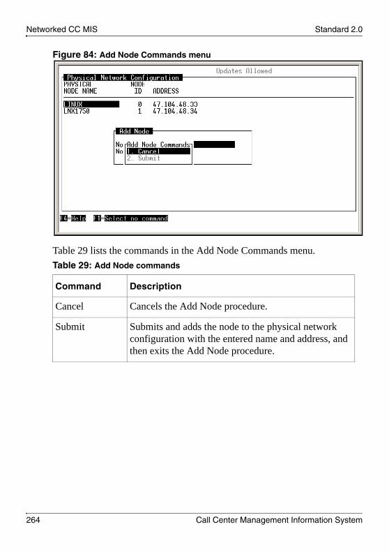
Networked CC MIS Standard 2.0
264 Call Center Management Information System
Figure 84: Add Node Commands menu
Table 29 lists the commands in the Add Node Commands menu.Table 29: Add Node commands
Command Description
Cancel Cancels the Add Node procedure.
Submit Submits and adds the node to the physical network configuration with the entered name and address, and then exits the Add Node procedure.

May 2007 Networked CC MIS
CC MIS Installation and Maintenance 265
Procedure 44: Deleting a node from the physical network
1 To delete a node from the physical network, select the Delete Node command (function key).
The Delete which physical node menu appears (see Figure 85).
Figure 85: Delete node menu
2 Select the node to delete from the list of nodes.
ATTENTION The following issues concern the deletion of a physical node:
You cannot delete a physical node if it is still referenced in a virtual network configuration (on this system). Deleting a physical node does not affect physical network or virtual network configurations on other CC MIS systems.

Networked CC MIS Standard 2.0
266 Call Center Management Information System
Partition configuration
When the network feature is enabled, you can define two types of partitions: local and Network Access Partition (NAP).
Local partitions are located on the physical node that stores CC MIS data (see “Local partitions” on page 197). NAPs are used to provide consolidated network-wide access to a set of local partitions in the network. NAPs can be added only if the Networking feature is enabled and the maximum number of NAPs is set greater than zero. Unlike local partitions, NAPs do not receive data from the switch, do not store data, and therefore, do not require any data storage parameters. You must define a NAP to access network CC MIS data. You can add NAPs only to a network node. This chapter describes the process for defining NAPs and establishing networks.
Figure 86: Partition Configuration screen

May 2007 Networked CC MIS
CC MIS Installation and Maintenance 267
Table 30 describes the function keys available on the Partition Configuration screen.Table 30: Function key commands
Key Description
Exit Exits the current screen.
Add Partition Adds a partition. A window appears in which you can select the partition type (Local or NAP) and enter the partition name.
Note: If NAPs are not allowed on the system (Maximum NAPs = 0), the partition type field does not appear in the pop-up window and the partition name is entered as described in Chapter 7, “Configuring the CC MIS application.”.
Delete Partition Deletes a partition. A window appears in which you can select the partition to delete. A confirmation window appears before the partition is deleted.
Note: The Delete Partition key is available only if a partition is configured.

Networked CC MIS Standard 2.0
268 Call Center Management Information System
Figure 87 shows the Partition Configuration screen with the Add Partition window and Partition Type pop-up menu.Figure 87: Add Partition options menu
Note: Select Local or NAP partition type from the pop-up menu. If the limits for both partition types are reached, the Add Partition function key does not appear on the screen. If the limit for only one partition type is reached, the function key appears on the screen. By default, the Partition Type field displays the partition type that has not reached its limit. If neither partition limit is reached, the default type is set to Local.
Figure 88 on page 269 shows the Partition Configuration screen with the Add Partition and Add Partition Commands menus displayed.

May 2007 Networked CC MIS
CC MIS Installation and Maintenance 269
Figure 88: Add Partition and Add Partition Commands menus
The commands in the Add Partition Commands menu are listed in Table 31.
Perform the steps in Procedure 45 to access the Partition Configuration menu and add a NAP.Procedure 45: Adding a NAP
1 Access the Maintenance and Administration main menu.
2 Type c to access the Configuration main menu.
The system displays the Configuration main menu.
3 Select Get Access Update Rights to switch to Updates Allowed mode.
Table 31: Add Partition Commands
Command Description
Cancel Cancels the Add Partition procedure.
Submit Adds the partition to the Partition Configuration screen and exits the Add Partition procedure.

Networked CC MIS Standard 2.0
270 Call Center Management Information System
4 Select Partition Configuration.
The system displays the Partition Configuration screen.
5 Press the Add Partition function key.
6 Press the Options functions key to display the Local/NAP pop-up menu and select NAP as the Partition Type.
7 Enter a Partition Name for the partition to add. The name can be up to 16 characters in length.
8 Press the Commands function key.
9 Select Submit to save the NAP.
Note: You can set a NAP can only to Setup or Product mode.

May 2007 Networked CC MIS
CC MIS Installation and Maintenance 271
Virtual network configuration
Use the Virtual Network Configuration screen to define which local partitions can be accessed from a NAP partition. These partitions comprise the virtual network with which the NAP is associated.
Figure 89 shows the Virtual Network Configuration screen.Figure 89: Virtual Network Configuration screen

Networked CC MIS Standard 2.0
272 Call Center Management Information System
Table 32 describes the fields on the Virtual Network Configuration screen.
Table 33 describes the function keys on the Virtual Network Configuration screen.
Table 32: Virtual Network Configuration field descriptions
Field Description
Physical Node Name The name of a physical node.
Physical Node ID The ID of a physical node.
Local Partition Name The name of the local partition on the physical node that can be accessed through the NAP.
Local Partition ID The ID of the local partition.
Partition Code An editable field in which you can enter a four character alphanumeric partition identifier.
Note: This identifier is used in a network to create unique agent IDs, subgroups, and position IDs.
Table 33: Virtual Network Configuration function keys (Part 1 of 2)
Key Description
Exit Exits the current screen.
Add Partition Adds a partition to the virtual network. This command displays a list of Physical Node/Local Partition pairs from which you can select a partition to add. Partitions that are already selected appear dimmed.

May 2007 Networked CC MIS
CC MIS Installation and Maintenance 273
Figure 90 shows the Add which partition to network menu.Figure 90: Add which partition to network menu
Delete Partition Deletes a partition from the virtual network. This command displays a list of Physical Node/Local Partition pairs from which to select a partition to delete. A prompt appears before the partition is deleted. This key does not appear if no partitions currently exist in the virtual network.
Table 33: Virtual Network Configuration function keys (Part 2 of 2)
Key Description

Networked CC MIS Standard 2.0
274 Call Center Management Information System
Figure 91 shows the Delete which partition from network menu.Figure 91: Delete which partition from network menu

May 2007 Networked CC MIS
CC MIS Installation and Maintenance 275
Figure 92 shows the Confirmation pop-up menu for the partition to delete. Figure 92: Delete partition from network confirmation pop-up

Networked CC MIS Standard 2.0
276 Call Center Management Information System
Deleting a partition
When you delete a partition in a network, you do not delete occurrences of that partition in the virtual network configuration on other nodes in the network or on the NAPs on the local node.
Note: This configuration information is not automatically deleted because nodes can be disconnected or down during configuration changes.
The following conventions are used when the partition name for a partition on a remote node cannot be determined:
If the partition has been deleted, the partition name appears as (DELETED).If the physical node is down, any partition names associated with the node appear as (UNAVAILABLE).
Perform the steps in Procedure 29 on page 211 to access the Partition Configuration menu and delete a partition.

CC MIS Installation and Maintenance 277
C h a p t e r 1 2
Monitoring system functions
In this chapterIntroduction . . . . . . . . . . . . . . . . . . . . . . . . . . . . . . . . . . . . . . . . . . . . . . 278
Logs . . . . . . . . . . . . . . . . . . . . . . . . . . . . . . . . . . . . . . . . . . . . . . . . . . . 279
View system monitor . . . . . . . . . . . . . . . . . . . . . . . . . . . . . . . . . . . . . . . 287
Trace Switch Link . . . . . . . . . . . . . . . . . . . . . . . . . . . . . . . . . . . . . . . . . 303
Physical Network Login. . . . . . . . . . . . . . . . . . . . . . . . . . . . . . . . . . . . . 319

Monitoring system functions Standard 2.0
278 Call Center Management Information System
Introduction
A number of CC MIS diagnostic tools are available through the Maintenance and Administration interface. This chapter provides procedures for the utilities available through the CC MIS Diagnostics screen.
Accessing the Diagnostics screen
Perform the steps in Procedure 46 to access the Diagnostics screen.Procedure 46: Accessing the Diagnostic menu
1 Access the Maintenance and Administration main menu.
2 Type d to access the Diagnostics screen.
The system displays the Diagnostics screen (see Figure 93).
Note: The screen shown in Figure 93 appears when CC MIS is running and when you are not dialed in remotely.
Figure 93: Diagnostics screen (when the software is running)

May 2007 Monitoring system functions
CC MIS Installation and Maintenance 279
Logs
The CC MIS system keeps many log files, which are available through the Diagnostics > Logs screen. CC MIS maintains the following log types:
System log—This log contains log messages generated by the CC MIS system. It contains informational and system error logs.Maintenance log—This log contains log messages generated by the Maintenance interface.Install log—This log contains information and errors pertaining to the installation process.Backup log—This log contains information and errors generated during the backup process.Restore log—This log contains information and errors generated during the restore process.Import log—This logs contains information and errors generated during the import process.
Perform the steps in Procedure 47 to select a log file.Procedure 47: Selecting a log file
1 Access the Maintenance and Administration main menu.
2 Type d to access the Diagnostics screen.
The system displays the Diagnostics screen.
3 Type l to display the Logs screen.
The system displays the Logs screen and the System Logs are displayed by default.
4 Press the Options function key.
The system displays the Log Files menu (see Figure 93 on page 278).

Monitoring system functions Standard 2.0
280 Call Center Management Information System
Figure 94: System Logs screen
5 Select a log file and press <enter>.
The choices are:
System log
Maintenance log
Install log
Backup log
Restore log
Import log

May 2007 Monitoring system functions
CC MIS Installation and Maintenance 281
Table 34 defines the fields on the Logs screen. Table 34: Logs screen fields
Parameter Description
Log Displays the name of the selected log file. Use the Options function key to select a different log file.
Partitions Used to select log messages for viewing or printing based on the partition with which the message is associated. The list of partitions can include one or more partition numbers or ranges separated by spaces. (For example, 0 2-5 7 12-14. ALL can be used to select all partitions.)
Note: The base partition is zero.
Start Time and Date The starting range (date and time) for the log messages to include.
End Time and Date The end range (date and time) for the log messages. Messages that occur after this date and time are not included.

Monitoring system functions Standard 2.0
282 Call Center Management Information System
Viewing a log
You can use the Commands menu to view the selected log file. For the system log, you can enter a date and time to view only those logs within the specified time range. You can also select specific partitions or all partitions.
Perform the steps Procedure 48 to view a log.Procedure 48: Viewing a log
1 Access the Maintenance and Administration main menu.
2 Type d to access the Diagnostics screen.
The system displays the Diagnostics screen.
3 Type l to display the Logs screen.
The system displays the Logs screen with System Logs selected by default.
4 Press the Options function key.
The system displays the list of available log files.
5 Select a log and press <enter>.
6 Use the Edit field function key to specify the partitions and start and end time ranges.
7 Press the Commands function key.
The system displays the commands available for selected log file.
8 Select the View command and press <enter>.
The system displays the viewer screen for the selected log.
9 When you finish viewing the log file, press the Exit function key to return to the Logs screen.
While viewing a log, you can perform a search on a string or expression contained in the log by pressing the Search key. In the search window, you can enter the following information:
the string or regular expression to search forwhether the search is case-sensitive (case-insensitive is the default)

May 2007 Monitoring system functions
CC MIS Installation and Maintenance 283
whether you want to do a text search or a regular expression search (text search is the default)the search options (these include search forward from cursor, search backward from cursor, search forward from top of file [default], and search backward from bottom of file)
The commands available when using the search option are Abort (default) and Search.
Abort returns you to the log viewer screen and cancels the search. Search initiates the search with the parameters that you specified.
After a search is complete, the Search Again key is activated in the log viewer screen. This option allows you to continue the previously performed search.

Monitoring system functions Standard 2.0
284 Call Center Management Information System
Monitoring a log
You can use the Monitor command to monitor the System Log or Maintenance Log as messages are received.
Note: The Monitor command is available only for the System Log and Maintenance Log. It is not available for the Install, Backup, Restore, or Import logs.
If the CC MIS system discontinues logging due to file size restrictions, you can use this command to view the log messages that are generated but not logged in the system log.
The Monitor command displays the last few logs on the screen and continues to monitor for new log messages. Log messages appear at the bottom of the list, scrolling the list up. The monitor data is not scrollable.
Perform the steps in Procedure 49 to monitor a log.Procedure 49: Monitoring a log
1 Access the Maintenance and Administration main menu.
2 Type d to access the Diagnostics screen.
The system displays the Diagnostics screen.
3 Type l to display the Logs screen.
The system displays the Logs screen with System Logs selected by default.
4 Press the Options function key.
The system displays the list of available log files.
5 Select either System log or Maintenance log and press <enter>.
6 Press the Commands function key.
The system displays the commands available for selection.
7 Select the Monitor command and press <enter>.
The system displays the Monitor screen for the selected log.

May 2007 Monitoring system functions
CC MIS Installation and Maintenance 285
8 Press <Ctrl>+c.
9 Press Exit to return to the Logs screen.
Printing a logThe Print command prints the selected log file. If you selected date and time filtering or partition on the System Log, only those messages within the entered date and time range are printed to the configured system default printer.
Perform the steps in Procedure 50 to print a log.Procedure 50: Printing a log
1 Access the Maintenance and Administration main menu.
2 Type d to access the Diagnostics screen.
The system displays the Diagnostics screen.
3 Type l to display the Logs screen.
The system displays the Logs screen with System Logs selected by default.
4 Press the Options function key.
The system displays the list of logs files available.
5 Select a log and press <enter>.
6 Press the Commands function key.
The system displays the commands available for selection.
7 Select the Print command and press <enter>.
The system sends the selected log to the default system printer.

Monitoring system functions Standard 2.0
286 Call Center Management Information System
Canceling the log printout
The Cancel Printing command cancels a previously requested log printout. Perform the steps in Procedure 51 to cancel a log printout.Procedure 51: Cancelling a log printout
1 Access the Maintenance and Administration main menu.
2 Type d to access the Diagnostics screen.
The system displays the Diagnostics screen.
3 Type l to display the Logs screen.
The system displays the Logs screen and the System Log is displayed by default.
4 Press the Options function key.
The system displays the list of available log files.
5 Select the log that is printing and press <enter>.
6 Press the Commands function key.
The system displays the commands available for selection.
7 Select the Cancel Printing command and press <enter>.
The system cancels the print job currently in progress.

May 2007 Monitoring system functions
CC MIS Installation and Maintenance 287
View system monitor
The System Monitor screen consists of up to seven status screens (depending on the type of partition):
Program (see page 288)Lock (see page 292)Partition (see page 294)Physical node (see page 301)Virtual node (see page 302)IP Port (see page 297)CPU Utilization (see page 299)
You can select the View System Monitor command from the Diagnostics screen.
Use the Commands menu to access the various status screens on the System Monitor screen. Pressing a function key displays the Commands menu. When you select a status screen, the System Monitor screen is redrawn with the selected status.
You can select how often the System Monitor updates its real-time information from the Commands menu. Valid refresh rates are 1 to 60 seconds in 1-second increments. The default is 5 seconds.

Monitoring system functions Standard 2.0
288 Call Center Management Information System
Program status
The Program Status screen appears by default when you select the View System Monitor command on the Diagnostics screen (see Figure 95).
Use Procedure 52 to view the System Monitor.Procedure 52: Accessing the System Monitor screen and selecting a status screen
1 Access the Maintenance and Administration main menu.
2 Type d to access the Diagnostics screen.
The system displays the Diagnostics screen.
3 Type v to display the System Monitor screen.
The System Monitor — Program Status screen appears as the default setting.
4 To change the view to another status screen, select the status option from the Commands menu (see Figure 95).
Figure 95: Program Status screen with Commands menu

May 2007 Monitoring system functions
CC MIS Installation and Maintenance 289
Table 35 defines the Program Status screen fields. Table 35: Program Status screen fields (Part 1 of 3)
Parameter Description
Program Name The name of the program.
CL Class S represents static (meaning that the program never goes away) and class T represents transient (meaning the program appears only when requested).
Flags The status flags are listed below (in order from left to right). The dash (-) indicates the flag is turned off or is reserved.No. Char. Description_________________________________________1. M The program is the current master time
source.2. A The program has acquired a source of
reliable time.3. S The program is a potential source of reliable
time.4. T The program is sensitive to abrupt time
change.5. 2 If the n flag (described below) is set; the
program that requested this program is sent a USR2 signal when this program dies.
6. 1 If the n flag (described below) is set; the program that requested this program is sent a USR1 signal when this program dies.

Monitoring system functions Standard 2.0
290 Call Center Management Information System
7. c A socket connection exists between this program and the program that requested it.
8. d The program is terminated if the program requesting it dies.
9. n The program that requested this program is notified when this program dies.
10. x The program is performing processing during which its normal sanity period is extended.
11. s The program is suspended (only applicable for static programs).
12. t This is the template for this program.
State The current state of program. Valid states are:
Run—Program is runningReady—Ready to runInit—InitializedKillP—Kill is pendingDying—System is killing program
User The CC MIS supervisor ID of the user using the program.
Service ID The ID assigned to each program. The format is <partition ID>.<process ID>
Requestor The service ID of the program requesting this program.
Table 35: Program Status screen fields (Part 2 of 3)
Parameter Description

May 2007 Monitoring system functions
CC MIS Installation and Maintenance 291
Prio The priority at which the program is running. The format is <priority type> <priority number>. Valid priority types are TS (time share) and RT (real-time). Processes with lower priority numbers are given higher priority. This column is blank for transient programs that have not been started.
Sanity The amount of time left before a program must report sanity again. Programs that do not report within the Sanity time are killed.
Lower portion of screen
Partition Type The partition type. A BASE program serves all partitions. A CUST or NAP program is an invocation of a program for a particular partition.
Start Prio The priority with which the program starts.
Transient Class The program transient class (USERS, REPORTS, PCWALLBOARDS, or None).
Args The arguments that were passed to the program when it started.
Table 35: Program Status screen fields (Part 3 of 3)
Parameter Description

Monitoring system functions Standard 2.0
292 Call Center Management Information System
Lock Status
You select the Lock Status option from the Commands menu. The System Monitor screen is redrawn to display the lock status (see Figure 96).Figure 96: Lock Status screen
Table 36 defines the Lock Status screen fields.Table 36: Lock Status screen fields (Part 1 of 2)
Parameter Description
Partition Number and type of partition (Base or Cust) in the format Partn ID: BASE or CUST.
Lock Name Name of the lock (for example, SYSDB or HBD_AGED).
Type Type of lock (database or resource).
Max Maximum number of locks granted on the resource. Blank indicates unlimited locks allowed.

May 2007 Monitoring system functions
CC MIS Installation and Maintenance 293
Status Current status states are: UnlockedSharedExclusive
GR Number of locks granted.
WT Number of programs waiting for a lock on that resource.
Note: The lower portion of the screen displays additional information about the lock. GR is the list of programs that have been granted a lock. WT is a list of programs that are waiting for a lock.
Table 36: Lock Status screen fields (Part 2 of 2)
Parameter Description

Monitoring system functions Standard 2.0
294 Call Center Management Information System
Partition status
When you select the Partition Status option from the Commands menu, the System Monitor screen is redrawn to display the partition status (see Figure 97).Figure 97: Partition Status screen
Table 37 defines the Partition Status screen fields.Table 37: Partition Status screen fields (Part 1 of 3)
Parameter Description
Type Type of partition (Base or Cust).
Flags Four flags are: d—deletings—partition stoppedn—partition is network accessiblet—template for this partition
Note: The dash (-) indicates that the flag is turned off.

May 2007 Monitoring system functions
CC MIS Installation and Maintenance 295
ID Numeric ID of the partition.
Parent ID of the parent partition of the partition.
Status Three status states are: Active—Online and workingReady— Stopped or not yet startedDying—In process of being shut down or deleted
Progs Active Number of programs running in the partition.
Time Zone The time zone.
CPU Time Total CPU time used by programs in this partition since it was created.
CPU % Percentage of CPU time currently being used by programs in this partition.This value is updated every 2 seconds.
Transient Program Class Information
When a partition is selected, additional information concerning transient programs for that partition appears in this area.
Class Transient class of REPORTS, USERS, or PCWALLBOARDS.
Limit The maximum number of each transient class allowed for this partition.
Active The count of programs of each transient class currently active.
Table 37: Partition Status screen fields (Part 2 of 3)
Parameter Description

Monitoring system functions Standard 2.0
296 Call Center Management Information System
Environment window
When a partition is selected, additional information concerning the partition appears in the lower portion of the screen when you select the Environment function key. An example of the information displayed about the selected partition is as follows:
CUSTDATA=/misdata/disk1/cust002
IPC=/mis/ipc/cust002
CUSTDB=/misdata/disk1/cust002/sysdb
...
...
Table 37: Partition Status screen fields (Part 3 of 3)
Parameter Description

May 2007 Monitoring system functions
CC MIS Installation and Maintenance 297
IP port status
When you select the IP Port Status option from the Commands menu, the System Monitor screen is redrawn to display IP port status (see Figure 98).Figure 98: Port Status screen
Table 38 describes the IP Port Status screen fields.Table 38: IP Port Status screen fields (Part 1 of 2)
Parameter Description
Port ID The protocol and port number of the IP port.
Function A brief functional description of the port.
Status If tthe system has opened the port, the status displays Active. Otherwise the status field is blank.
Connects The number of valid connection attempts on the port since the system started.

Monitoring system functions Standard 2.0
298 Call Center Management Information System
Bad Addr The number of connection attempts on the port from unconfigured PCs.
Bad State The number of invalid connection attempts that failed because the partition the user was attempting to connect to was down.
> Limit The number of valid connection attempts where connection would exceed the transient program limit for the partition.
Table 38: IP Port Status screen fields (Part 2 of 2)
Parameter Description

May 2007 Monitoring system functions
CC MIS Installation and Maintenance 299
CPU utilization
When you select the CPU Utilization option from the Commands menu, the System Monitor screen is redrawn to display CPU utilization (see Figure 99).Figure 99: CPU Utilization screen
Table 39 describes the CPU Utilization status screen fields.Table 39: CPU Utilization screen fields (Part 1 of 2)
Parameter Description
Program Name The name of the program.
Service ID The ID assigned to each program. The format is <partition ID>.<process ID>. Partition ID 0 is reserved for the base partition. This column is blank for transient programs that have not yet started.

Monitoring system functions Standard 2.0
300 Call Center Management Information System
KBytes The amount of memory in kilobytes currently used by the program. This number includes attached shared memory, so the total number can be greater than the total number of kilobytes used by all programs in this list.
CPU TIME Total CPU time used by the program since it started.
Percentage Utilization — Inst
Percentage of CPU usage during the last 5 seconds.
Percentage Utilization — Life
Percentage of CPU usage since the system started.
Percentage Utilization— Avg
Percentage of CPU usage since reset (refer to Reset averages key—see page 300).
Percentage Utilization — Period
Time since reset (refer to Reset averages key—see page 300).The lower portion of the screen displays the CPU Time and Percentage Utilization values for the entire CC MIS system.The Reset averages key resets the PERIOD counter and the AVG PERCENTAGE counter for the program the cursor is positioned on, for the total CPU utilization, or for all programs and the total CPU utilization (depending on which is selected).
Table 39: CPU Utilization screen fields (Part 2 of 2)
Parameter Description

May 2007 Monitoring system functions
CC MIS Installation and Maintenance 301
Additional System Monitor screens
The Physical Node Status and Virtual Node Status screens are available from the System Monitor Commands menu when the Networking feature is enabled.
Physical Node StatusFigure 100 shows the Physical Node Status screen.
Figure 100: Physical Node Status screen

Monitoring system functions Standard 2.0
302 Call Center Management Information System
Virtual Node StatusFigure 100 shows the Virtual Node Status screen. This screen displays information concerning the partitions (virtual nodes) that are included in the network.
Figure 101: Virtual Node Status screen

May 2007 Monitoring system functions
CC MIS Installation and Maintenance 303
Trace Switch Link
You can use the Trace Switch Link command to capture the messages sent between the ACD switch and the CC MIS system for debugging purposes. The output from the Trace Switch Link command is a useful diagnostic tool for determining the interactions between the ACD switch and the downstream processor.
Note: The Trace Switch Link command can capture the initialization data received from the host switch in a Link Trace file. When Trace Switch Link is started and stopped, the on or off state is written to a file that CC MIS can check upon startup. If Trace Switch Link is on when CC MIS starts, the system can immediately begin the Trace Switch Link and the initialization data is captured and can be analyzed.
Perform the steps in Procedure 53 to access the Link Trace screen.Procedure 53: Accessing the Link Trace screen
1 Access the Maintenance and Administration main menu.
2 Type d to access the Diagnostics screen.
The system displays the Diagnostics screen.
3 Type t to access the Link Trace screen.
The system displays the Link Trace screen (see Figure 102 on page 304).

Monitoring system functions Standard 2.0
304 Call Center Management Information System
Figure 102: CC MIS Link Trace screen
Table 40 describes the menu options on the Link Trace screen. Table 40: Link Trace menu options (Part 1 of 2)
Menu option Descriptions
Start Link TraceStop Link Trace
This command starts the Link Trace.This command stops the Link Trace after it was started with the Start Link Trace command. When the Link Trace is stopped, this command is replaced with Start Link Trace.
View Link Trace This command displays the hexadecimal Link Trace file (see Figure 105 on page 307). Use the Exit function key to exit the viewer.

May 2007 Monitoring system functions
CC MIS Installation and Maintenance 305
View Translated Link Trace
This command displays the translated version of the Link Trace file. When you select this command, the Message Translator Filter screen appears (see Figure 108 on page 312). You can use this screen to select the types of messages to translate from their hexadecimal representation to a readable format. More help is available from the Message Translator Filter screen.
Print Link Trace This command prints the untranslated hexadecimal Link Trace file to the default system printer.
Print Translated Link Trace
This command prints the translated version of the Link Trace file to the default system printer. When you select this command, the Message Translator Filter screen appears. Choose which types of messages to translate from their hexadecimal representation to a readable format and print. More help is available from the Message Translator Filter screen.
Select Different Link This screen provides the capability to select a different link for the Link Trace commands.
Table 40: Link Trace menu options (Part 2 of 2)
Menu option Descriptions

Monitoring system functions Standard 2.0
306 Call Center Management Information System
Figure 103 shows a sample Link Trace screen. A prompt appears at which you can specify the link number for which tracing is desired.Figure 103: Link Trace screen (multiple links)
Note: The commands listed on the Link Trace screen relate to the link displayed in the title.
When multiple links are defined, a prompt appears requesting you to select the link on which the Link Trace commands are to operate. Figure 103 shows the prompt that appears the first time you select the Link Trace command.
Use the Select Different Link command on the Link Trace menu (see Figure 102 on page 304) to select a different link for the Link Trace commands. Use the View Translated Link Trace and Print Translated Link Trace commands to choose which type of messages to translate from their hexadecimal representation to a readable format.
Figure 104 on page 307 is an example of the Message Translator Filter screen.

May 2007 Monitoring system functions
CC MIS Installation and Maintenance 307
Figure 104: CC MIS Message Translator Filter screen
When Link Trace translating is turned on, the hexadecimal notation in the Link Trace file is translated into a readable format. You can use the translated version of Link Trace if a protocol guide is not available to interpret the hexadecimal file.
Figure 105 shows an example of the untranslated Link Trace file. Figure 106 on page 308 shows an example of the same messages in the translated form.Figure 105: Untranslated Link Trace file example

Monitoring system functions Standard 2.0
308 Call Center Management Information System
Figure 106: Translated Link Trace file example
In Figure 105 on page 307 and Figure 106, messages marked by dsp are messages sent from the downstream processor (CC MIS) to the ACD host switch. Those marked with swx are messages sent from the ACD host switch to the downstream processor. The InvokedID acts as a sequence number that associates individual operation invocations with operation results.

May 2007 Monitoring system functions
CC MIS Installation and Maintenance 309
Starting and stopping the Link Trace
The Start Link Trace command is a toggle command that allows Link Trace to be turned on and off. When Link Trace is turned on, the command is Stop Link Trace. When the Link Trace is turned off, the command is Start Link Trace.
Perform the steps in Procedure 54 to use the Start/Stop Link Trace command.Procedure 54: Starting and stopping a Link Trace
1 Access the Maintenance and Administration main menu.
2 Type d to access the Diagnostics screen.
The system displays the Diagnostics screen.
3 Enter t to access the Link Trace screen.
The system displays the Link Trace screen.
4 Enter the link number.
Note: The link number is specified only if multiple links can be traced.
5 Press s and <enter> to start the Link Trace.
The system turns Link Trace on.
Note: If Link Trace is on, the Link Trace screen displays the Stop Link Trace command instead of Start Link Trace. To stop the Link Trace after it is activated, press s and <enter>.

Monitoring system functions Standard 2.0
310 Call Center Management Information System
Viewing the Link Trace
Use the View Link Trace command to view the untranslated hexadecimal Link Trace file. Perform the steps in Procedure 55 to use the View Link Trace command.
Note: The View Link Trace command is available only if a trace file exists.
Procedure 55: Viewing a Link Trace
1 Access the Maintenance and Administration main menu.
2 Type d to access the Diagnostics screen.
The system displays the Diagnostics screen.
3 Enter t to access the Link Trace screen.
The system displays the Link Trace screen.
4 Type v to view a Link Trace.
The system displays the Trace Dump screen with the untranslated hexadecimal Link Trace file.
Figure 107: Trace dump

May 2007 Monitoring system functions
CC MIS Installation and Maintenance 311
Viewing the translated Link Trace
Use the View Translated Link Trace command to view the translated version of the Link Trace file, instead of the hexadecimal file. When you choose this command, the Message Translator Filter screen appears, in which you can choose which messages to translate for viewing.
Perform the steps in Procedure 56 to use the View Translated Link Trace command.
Note: This command is available only if a Link Trace file exists.
Procedure 56: Viewing a translated Link Trace file
1 Access the Maintenance and Administration main menu.
2 Type d to access the Diagnostics screen.
The system displays the Diagnostics screen.
3 Enter t to access the Link Trace screen.
The system displays the Link Trace screen.
4 Type vt to view the translated Link Trace.
The system displays the Message Translator Filter screen (see Figure 108 on page 312).

Monitoring system functions Standard 2.0
312 Call Center Management Information System
Figure 108: Message Translator Filter screen
5 Type p to proceed with the View command.
The system displays the Translated Trace file (see Figure 109).
Figure 109: Translated Link Trace file

May 2007 Monitoring system functions
CC MIS Installation and Maintenance 313
Using the Search function
You can use the Search command on the Translated Trace screen to search for a specific entry within the Link Trace file. The Search command is located at the bottom of the Translated Trace screen.
The Search screen (as shown in Figure 110) appears when you press the Search function key. Figure 110: Search screen
To access instructions for using the Search function, press the Options function key.

Monitoring system functions Standard 2.0
314 Call Center Management Information System
Figure 111: Search options pop-up

May 2007 Monitoring system functions
CC MIS Installation and Maintenance 315
Printing the Link Trace file
You can print the untranslated hexadecimal Link Trace file using the Print Link Trace command.
Note: This command is available only if a trace file exists and the system default printer is configured.
Perform the steps in Procedure 57 to use the Print Link Trace command.Procedure 57: Printing a Link Trace file
1 Access the Maintenance and Administration main menu.
2 Type d to access the Diagnostics screen.
The system displays the Diagnostics screen.
3 Type t to access the Link Trace screen.
The system displays the Link Trace screen.
4 Type p to access the Print Link Trace.
The system sends the current Link Trace file to the system default printer.

Monitoring system functions Standard 2.0
316 Call Center Management Information System
Printing the translated Link Trace
Use the Print Translated Link Trace command to print the translated Link Trace file, rather than the untranslated hexadecimal file.
Note: This command is available only if a Link Trace file exists and the system default printer is configured.
When you select this command, the Message Translator Filter screen appears, in which you can choose which messages to translate and print.
Perform the steps in Procedure 58 to use the Print Translated Link Trace command.Procedure 58: Printing a translated Link Trace file
1 Access the Maintenance and Administration main menu.
2 Type d to access the Diagnostics screen.
The system displays the Diagnostics screen.
3 Type t to access the Link Trace screen.
The system displays the Link Trace screen.
4 Type pt to access the Print Translated Link Trace.
The system displays the Message Translator Filter screen.
5 Type p to proceed with the Print command.
The system sends the translated Link Trace file to the system default printer.

May 2007 Monitoring system functions
CC MIS Installation and Maintenance 317
Canceling Link Trace printing
You can cancel the printing of a Link Trace file with the Cancel Printing command.
Note: The Cancel Printing command is available only if you printed a Link Trace file.
Perform the steps in Procedure 59 to use the Cancel Printing command.Procedure 59: Cancelling Link Trace printing
1 Access the Maintenance and Administration main menu.
2 Type d to access the Diagnostics screen.
The system displays the Diagnostics screen.
3 Type t to access the Link Trace screen.
The system displays the Link Trace screen.
4 Press c and <Return>.
The system cancels the current Link Trace print job.

Monitoring system functions Standard 2.0
318 Call Center Management Information System
Selecting a different Link
Use the Select Different Link command to select a different link for the trace commands.
Perform the steps in Procedure 60 to use the Select Different Link command.Procedure 60: Selecting a different link for Link Trace
1 Access the Maintenance and Administration main menu.
2 Type d to access the Diagnostics screen.
The system displays the Diagnostics screen.
3 Type t to access the Link Trace screen.
The system displays the Link Trace screen.
4 Press l to access the Select Different Link option.
The system displays the Trace Link screen (see Figure 112).
Figure 112: Trace Link screen
5 Enter the new link number.
The Link Trace screen appears.

May 2007 Monitoring system functions
CC MIS Installation and Maintenance 319
Physical Network Login
The Physical Network Login option is available on the Diagnostics screen when the Networking feature is enabled.
The Physical Network Login screen (Figure 113) appears when you select the Physical Network Login option. This screen provides access to other nodes in your physical network.
Use the steps in Procedure 61 to access the Physical Network Login screen.Procedure 61: Physical Network Login screen
1 Access the Maintenance and Administration main menu.
2 Type d to access the Diagnostics screen.
The system displays the Diagnostics screen.
3 Type p to access the Physical Network Login screen.
The system displays the Physical Network Login screen (see Figure 113).
Figure 113: Physical Network Login screen

Monitoring system functions Standard 2.0
320 Call Center Management Information System
4 To log on to a physical node in the network, use the arrow keys to select the appropriate node, and then press the Commands function key.
A commands menu appears, from which you can exit or log on through Telnet (see Figure 114).
Figure 114: Commands menu
5 Select the Telnet option.
The login prompt appears (see Figure 115 on page 321).

May 2007 Monitoring system functions
CC MIS Installation and Maintenance 321
Figure 115: Login prompt
6 Enter your logon information.

Monitoring system functions Standard 2.0
322 Call Center Management Information System

CC MIS Installation and Maintenance 323
C h a p t e r 1 3
Switch configuration data updates
In this chapterIntroduction . . . . . . . . . . . . . . . . . . . . . . . . . . . . . . . . . . . . . . . . . . . . . . 324
Accessing the Update Switch Configuration Data screen. . . . . . . . . . . 325

Switch configuration data updates Standard 2.0
324 Call Center Management Information System
Introduction
Use the Update Switch Configuration Data command to manually initiate an update of ACD configuration data received from the switch. This function causes the CC MIS system to request that the switch resend all initialization data for a selected link to the CC MIS system. This command is useful for updating the CC MIS ACD configuration information after you add or delete ACD groups, positions, or subgroups on the switch.
This is the same function that runs automatically each day at the time defined by the Reinit Time field in the Switch Link Definition screen (see “Switch link configuration” on page 140).

May 2007 Switch configuration data updates
CC MIS Installation and Maintenance 325
Accessing the Update Switch Configuration Data screen
Perform the steps in Procedure 62 to access the Update Switch Configuration Data screen.Procedure 62: Accessing the Update Switch Configuration Data screen
1 Access the Maintenance and Administration main menu.
2 Type r to select Run State Utilities.
The system displays the Run State Utilities menu (see Figure 116 on page 325).
Figure 116: Run State Utilities menu
3 Type u to select the Update Switch Configuration Data command.
The system displays the Update Switch Configuration screen.
For single links, enter y to run the switch configuration update for the specified link (or type q to quit without running the update). Figure 117 on page 326 shows an example of the prompt for a single link.

Switch configuration data updates Standard 2.0
326 Call Center Management Information System
For multiple links, enter the link number of the link to update (or type q to quit without running the update). Figure 118 shows an example of the prompt for multiple links
Note: Reinitialization of a link affects only partitions using that link.
Figure 117: Update Switch Configuration screen (single link)
Figure 118: Update Switch Configuration screen (multiple links)

CC MIS Installation and Maintenance 327
C h a p t e r 1 4
SNMP MIB transfer
In this chapterIntroduction . . . . . . . . . . . . . . . . . . . . . . . . . . . . . . . . . . . . . . . . . . . . . . 328
Accessing the SNMP Transfer screen. . . . . . . . . . . . . . . . . . . . . . . . . . 329

SNMP MIB transfer Standard 2.0
328 Call Center Management Information System
Introduction
You can use the Transfer SNMP MIB Definitions command on the System Upgrade Utility menu to transfer the CC MIS System MIB and CC MIS Partition MIB definition files to selected Network Management Systems (NMS).
Note: The Transfer SNMP MIB Definitions command appears on this menu only when the SNMP option is enabled for the system.

May 2007 SNMP MIB transfer
CC MIS Installation and Maintenance 329
Accessing the SNMP Transfer screen
Perform the steps in Procedure 63 to access the SNMP Transfer screen.Procedure 63: Accessing the SNMP Transfer screen
1 Access the Maintenance and Administration main menu.
2 Type s to access the System Upgrade Utilities menu.
The system displays the System Upgrade Utilities menu (see Figure 119).
Figure 119: System Upgrade Utilities menu
3 Type t to select the Transfer SNMP MIB Definitions command.
The SNMP MIB Transfer Definition screen appears (see Figure 120).

SNMP MIB transfer Standard 2.0
330 Call Center Management Information System
Figure 120: Transfer SNMP MIB definitions to a Network Management System
4 During the SNMP transfer session, you are prompted for the following information:
a. MIBs to be transferred: You can transfer just the system MIB, just the partition MIB, or both. (If you select the partition MIB, one MIB file is transferred for each partition defined on the CC MIS system.)
b. IP address: The IP address of the computer to which the files are transferred.
c. user ID: The user ID on the remote computer to which the MIB files are transferred.
d. target directory: The directory in which to place the MIB definition files on the remote computer.
e. password: The password for the specified user on the remote computer.
Figure 121 on page 331 show a sample SNMP transfer session.

May 2007 SNMP MIB transfer
CC MIS Installation and Maintenance 331
Figure 121: Sample SNMP transfer session

SNMP MIB transfer Standard 2.0
332 Call Center Management Information System

CC MIS Installation and Maintenance 333
A p p e n d i x A
Switch link datafill requirements
In this appendixIntroduction . . . . . . . . . . . . . . . . . . . . . . . . . . . . . . . . . . . . . . . . . . . . . . 334
Office parameters . . . . . . . . . . . . . . . . . . . . . . . . . . . . . . . . . . . . . . . . . 335
Data link datafill. . . . . . . . . . . . . . . . . . . . . . . . . . . . . . . . . . . . . . . . . . . 336
Standard datafill example . . . . . . . . . . . . . . . . . . . . . . . . . . . . . . . . . . . 344

Switch link datafill requirements Standard 2.0
334 Call Center Management Information System
Introduction
This appendix outlines the switch datafill required to properly configure a data link to the CC MIS system.

May 2007 Switch link datafill requirements
CC MIS Installation and Maintenance 335
Office parameters
The following office parameters can affect CC MIS data links to the switch:
NOP_USERID_SECURITY_ACCESS — Table OFCENGThis parameter configures restricted access to the switch by user ID. By default, this parameter is set to N. Set this field to Y to restrict access to the switch, and then configure the following:
1. Define the user ID and password for the switch using the PERMIT command. The user ID and password fields must match the ACD User ID and ACD User Password fields. These fields are defined in the CC MIS switch link definition that is used to access this switch. Switch link definitions are defined through the Configuration menu in the CC MIS Maintenance and Administration interface.
2. Define the applications that can be accessed by the user defined in table NOPUSERS. The only application that is required for ACDMIS is ACDMIS_APPL.
ACD_MIS_OUT_EVENT_BUFFER_SIZE — Table OFCENGThis parameter is required to determine the outgoing event buffer size allocated for ACDMIS sessions. Specify a value between 100 and 200. The default value is 110. For high traffic links, Nortel recommends that you use 200.NOS_QUANTITY_OF_SVCS — Table OFCENGThe maximum number of ACDMIS sessions on a switch is equal to the value of this parameter or the value of MAX_ACDMIS_SESSIONS, whichever is the lower value. Specify a value between 1 and 60. The default value is 5.MAX_ACDMIS_SESSIONS — Table OFCOPTThis specifies the maximum number of ACDMIS sessions on the switch. Specify a value between 0 and 60. The default value is 5.
All other datafill is standard as described in “Data link datafill” on page 336.

Switch link datafill requirements Standard 2.0
336 Call Center Management Information System
Data link datafill
This section describes the standard datafill requirements on the switch for an ACDMIS data link to CC MIS.
The majority of the datafill is the same regardless of the type of switch equipment that is used to make the connection (that is, Enhanced Multi-Protocol Controller [EMPC] card or Input/Output Module [IOM]). Where a different value is required in the datafill based on the type of equipment used, the differences are noted.
If a value in Table 41 is in italics, the value is a variable that must be determined from the switch configuration for the site. Table 41: Data link datafill (Part 1 of 8)
Switch Table Field Value Description
MPC MPCNO n The MPC numberThis number is assigned sequentially in the table.
MPCIOC n The Input/Output Controller (IOC) on which the MPC card resides.
IOCCT n The bottom circuit number of the MPC card determined by the position in the IOC. The number must be a multiple of four.

May 2007 Switch link datafill requirements
CC MIS Installation and Maintenance 337
EQ 1X89BB Indicates EMPC-type equipment (the older 1X89BA card can also be used).
FX30AA Indicates IOM-type equipment.
DLDFILE MPCnnnxx The download file for MPC equipment. Select the latest available load that supports the X2584 protocol.
IOM$LOAD The download file for IOM equipment.
MPCLINK LINKKEY n The MPC number and link number.
MPCNO n The number assigned to the MPC card. This number must match the number assigned in the MPC table.
LINKNO n For EMPC, specify which of the two synchronous MPC links is used (2 or 3).
3 For IOM, always specify a value of 3.
LINKALM Y Turns on link alarms.
Table 41: Data link datafill (Part 2 of 8)
Switch Table Field Value Description

Switch link datafill requirements Standard 2.0
338 Call Center Management Information System
PRTCLDAT X2584 Specifies the 1984 version of the X.25 standard.
LINKNABL 0 Specifies 0 as the number of minutes a link can remain in the enabling state before it is busied out and reset.
CONVNABL 0 Specifies 0 as the number of minutes data transmission on the link can remain enabled without restarting the link.
L2WINDOW 7 Specifies the frame window size as 7.
L3DATA P256 Specifies the packet size as 256 bytes.
NODETYPE DTE Specifies the datalink to act as a DTE.
CLKSRCE EXTERNAL Specifies that external clocking is used.
SVCS2WAY 2 Specifies that there are two 2-way switched virtual circuits.
Table 41: Data link datafill (Part 3 of 8)
Switch Table Field Value Description

May 2007 Switch link datafill requirements
CC MIS Installation and Maintenance 339
ELECSPEC RS232 or V35
Specifies the connection to use. Use RS232 if the RS-232 connector is used. Use V35 if the V.35 connector is used.
T1_10MS 150 Specifies the Ack timeout.
T2_10MS 20 Specifies the send Ack guideline.
L3WINDOW 7 Specifies that the packet window size is 7.
THRUPUT T48000 Specifies that the output throughput class is T48000.
L3ACK 10 Specifies that the Level 3 Ack timer is 10.
Note: Ignore the L3ACK switch warning when datafilling this parameter.
SVCDNA nnnnnnnn Specify an eight-digit X.121 address for this datalink.
Table 41: Data link datafill (Part 4 of 8)
Switch Table Field Value Description

Switch link datafill requirements Standard 2.0
340 Call Center Management Information System
GDLADEV APPLN NOP Specifies that NOP is used as the data transfer application.
DEVICE MPC Specifies MPC as the device that can be associated with the data transfer application.
NOPADDR INDEX n Assign a number from 0–63 to identify the ACD MIS data link from which the switch receives data.
UNIT n Specify the MPC number previously assigned in the MPC table.
LINK n Specify the MPC data link previously assigned in the MPCLINK table.
ADDRESS nnnnnnnn Specify the Network Operations System Address of the data link. The address must match what was previously defined in the MPCLINK table.
PROTOCOL 0 0 0 0 Valid protocol entry.
Table 41: Data link datafill (Part 5 of 8)
Switch Table Field Value Description

May 2007 Switch link datafill requirements
CC MIS Installation and Maintenance 341
NOPAPPLN DNAKEY xxxxxxxx The Data Network Address. The address must match what was previously defined in the NOPADDR table.
APPLNS ALL or ONLY
Enter ONLY if you want the Remote Operation service to restrict which applications a Data Network Address is authorized to access.
APPLICATION_ID
ACDMIS_APPL
Enter ACDMIS_APPL only if APPLNS = ONLY.
Table 41: Data link datafill (Part 6 of 8)
Switch Table Field Value Description

Switch link datafill requirements Standard 2.0
342 Call Center Management Information System
ACDMISPL POOL xxxxxxxx The ACD pool name. The name must match the value that is configured on the CC MIS for the switch link.
PASSWORD xxxxxxxx The ACD pool password. The password must match the value that is configured on the CC MIS for the switch link.
PROTOCOL BCSnn Specifies which ACD MIS protocol to run. Supported protocols are BCS 35 and BCS 43. Nortel recommends BCS 43.
OUTEVENT 200 Specifies the maximum number of events held in the outgoing buffer.
BUNDLING Y Specifies whether messages are bundled together in outgoing packets for better performance.
Table 41: Data link datafill (Part 7 of 8)
Switch Table Field Value Description

May 2007 Switch link datafill requirements
CC MIS Installation and Maintenance 343
ACDMISSP SUBPOOL xxxxxxxx The ACD subpool name. The name must match the value that is configured on the CC MIS.
PASSWORD xxxxxxxx The ACD subpool password. The password must match the value that is configured on the CC MIS.
POOL xxxxxxxx This value must match the value that was previously configured in the ACDMISPL table.
Table 41: Data link datafill (Part 8 of 8)
Switch Table Field Value Description

Switch link datafill requirements Standard 2.0
344 Call Center Management Information System
Standard datafill example
Table 42 shows an example of minimum datafill for a switch with the typical values specified. Table 42 is a duplication of Table 41 on page 336 with example values assigned to the various parameters.
This configuration set should ensure that a valid set of parameters exists on the switch for operation with CC MIS. Some of the link tables (that is, MPC and MPCLINK) vary from switch to switch depending site-specific configuration.Table 42: Data link datafill example (Part 1 of 7)
Switch Table Field Value Description
MPC MPCNO 6 The MPC numberThe number is assigned sequentially in the table.
MPCIOC 2 The IOC on which the MPC card resides.
IOCCT 20 The bottom circuit number of the MPC card determined by the position in the IOC. Must be a multiple of four.
EQ 1X89BB 1X89BB indicates EMPC type equipment.
DLDFILE MPC403AC For EMPC card supporting the X2584 protocol.

May 2007 Switch link datafill requirements
CC MIS Installation and Maintenance 345
MPCLINK LINKKEY 6 The MPC number and the link number.
MPCNO 6 The number assigned to the MPC card. This number must match the number assigned in the MPC table.
LINKNO 2 Specify which of the two synchronous MPC links is used (2 or 3).
LINKALM Y Turns on link alarms.
PRTCLDAT X2584 Specifies the 1984 version of the X.25 standard.
LINKNABL 0 Specifies 0 as the number of minutes a link can remain in the enabled state before it is busied out and reset.
CONVNABL 0 Specifies 0 as the number of minutes that data transmission on the link that can remain enabled without restarting the link.
L2WINDOW 7 Specifies the frame window size as 7.
L3DATA P256 Specifies the packet size as 256 bytes.
Table 42: Data link datafill example (Part 2 of 7)
Switch Table Field Value Description

Switch link datafill requirements Standard 2.0
346 Call Center Management Information System
NODETYPE DTE Specifies the datalink to act as a DTE.
CLKSRCE EXTERNAL Specifies that external clocking is used.
SVCS2WAY 2 Specifies that there is two 2-way switched virtual circuits.
ELECSPEC RS232 Specifies that the connection is RS232.
N2 20 Specifies the frame retransmission count is 20.
T1_10MS 150 Specifies the Ack timeout is 1.5 seconds.
T2_10MS 20 Specifies that the send Ack guideline is 20.
T4_S 2 Specifies that the idle frame transmission time is 2.
T3_S 10 Specifies that the idle link timer is 10.
L3WINDOW 7 Specifies that the packet window size is 7.
THRUPUT T48000 Specifies that the output throughput class is T48000.
Table 42: Data link datafill example (Part 3 of 7)
Switch Table Field Value Description

May 2007 Switch link datafill requirements
CC MIS Installation and Maintenance 347
L3ACK 10 Specifies the Level 3 Ack timer is10.
SVCDNA 23456789 Specify an eight digit X.121 address for this datalink.
GDLADEV APPLN NOP Specifies NOP as the data transfer application that is used.
DEVICE MPC Specifies MPC as the device that is associated with the data transfer application.
Table 42: Data link datafill example (Part 4 of 7)
Switch Table Field Value Description

Switch link datafill requirements Standard 2.0
348 Call Center Management Information System
NOPADDR INDEX 18 Assign the identify the ACD MIS data link from which the switch receives data.
UNIT 6 Specify the MPC number previously assigned in the MPC table.
LINK 2 Specify the MPC data link previously assigned in the MPCLINK table.
ADDRESS 23456789 Specify the Network Operations System Address of the data link. This address must match what was previously defined in the MPCLINK table.
PROTOCOL 0 0 0 0 Valid protocol entry.
Table 42: Data link datafill example (Part 5 of 7)
Switch Table Field Value Description

May 2007 Switch link datafill requirements
CC MIS Installation and Maintenance 349
NOPAPPLN DNAKEY 98765432 The Data Network Address. Must be the same as what was previously defined in the NOPADDR table.
APPLNS ALLor ONLY
Enter ONLY if you wish the Remote Operation service to restrict which applications a Data Network Address is authorized to access.
APPLICATION_ID
ACDMIS_APPL
Enter ACDMIS_APPL only if field APPLNS = ONLY.
ACDMISPL POOL ACDPOOL1 The ACD pool name.
PASSWORD ACDACD The ACD pool password.
PROTOCOL BCS43 Set the ACDMIS protocol to BCS 43.
OUTEVENT 200 Set the value representing the number of events held in the outgoing buffer.
BUNDLING Y Enables message bundling.
Table 42: Data link datafill example (Part 6 of 7)
Switch Table Field Value Description

Switch link datafill requirements Standard 2.0
350 Call Center Management Information System
ACDMISSP SUBPOOL ACDSUB1 The ACD subpool name.
PASSWORD ACDACD The ACD subpool password.
POOL ACDPOOL1 Set the ACD pool.
Table 42: Data link datafill example (Part 7 of 7)
Switch Table Field Value Description

CC MIS Installation and Maintenance 351
A p p e n d i x B
TCP/X.25 bridge devices
In this appendixIntroduction . . . . . . . . . . . . . . . . . . . . . . . . . . . . . . . . . . . . . . . . . . . . . . 352
TCP/X.25 bridge solutions . . . . . . . . . . . . . . . . . . . . . . . . . . . . . . . . . . 353

TCP/X.25 bridge devices Standard 2.0
352 Call Center Management Information System
Introduction
Where X.25 switch connectivity is required, you must use a TCP/IP bridge device, configured to bridge between an IP connection from the CC MIS server to an X.25 connection to the switch (see Figure 122).Figure 122:
This appendix provides recommended solutions for the TCP/X.25 bridge device.
DMS-100 CC MISTCP/X.25
bridge
device
EMPC or IOM port
TCP/IPX.25

May 2007 TCP/X.25 bridge devices
CC MIS Installation and Maintenance 353
TCP/X.25 bridge solutions
Nortel ARN
The Nortel Advanced Remote Node (ARN) is legacy equipment that you can use to provide the IP to X.25 bridge between the CC MIS server and the DMS-ACD. The Nortel ARN retires August, 2007.
For more information about installing and configuring the ARN, see Appendix C, “TCP/IP switch links using ARN.”
Other tested solutions
Nortel has tested the following original manufacturer equipment (OEM) solutions for use as a TCP/X.25 bridge device with CC MIS:
Develcon Athena Access (www.develcon.com)FarSite Communications FarLinx TCP-X25 Gateway (www.farsite.co.uk)
For more information about configuring the Develcon Athena Access or the FarSite Communications FarLinx TCP-X.25 Gateway, see the relevant Distributor Technical Reference (DTR) documents. DTRs are available on the Nortel Partner Information Center Web site at www.nortel.com/pic.

TCP/X.25 bridge devices Standard 2.0
354 Call Center Management Information System

CC MIS Installation and Maintenance 355
A p p e n d i x C
TCP/IP switch links using ARN
In this appendixIntroduction . . . . . . . . . . . . . . . . . . . . . . . . . . . . . . . . . . . . . . . . . . . . . . 356
Regional requirements . . . . . . . . . . . . . . . . . . . . . . . . . . . . . . . . . . . . . 357
Purpose. . . . . . . . . . . . . . . . . . . . . . . . . . . . . . . . . . . . . . . . . . . . . . . . . 359
Feature definition . . . . . . . . . . . . . . . . . . . . . . . . . . . . . . . . . . . . . . . . . 360
Before you begin . . . . . . . . . . . . . . . . . . . . . . . . . . . . . . . . . . . . . . . . . . 364
Installing the Advanced Remote Node (ARN). . . . . . . . . . . . . . . . . . . . 365
Configuring the Ethernet link on the ARN. . . . . . . . . . . . . . . . . . . . . . . 379
Installing Site Manager . . . . . . . . . . . . . . . . . . . . . . . . . . . . . . . . . . . . . 388
Configuring an X.25 link on the ARN . . . . . . . . . . . . . . . . . . . . . . . . . . 396
CC MIS TCP/IP switch link configuration . . . . . . . . . . . . . . . . . . . . . . . 422
Postinstallation activities . . . . . . . . . . . . . . . . . . . . . . . . . . . . . . . . . . . . 426
References . . . . . . . . . . . . . . . . . . . . . . . . . . . . . . . . . . . . . . . . . . . . . . 430

TCP/IP switch links using ARN Standard 2.0
356 Call Center Management Information System
Introduction
This appendix is an installation tool intended for Nortel personnel only. This appendix provides a guide for installing and configuring the Advanced Remote Node (ARN) router to provide X.25 connectivity to the DMS switch from the Ethernet interface on a CC MIS server.
The ARN can be used with CC MIS Software Release 5.1 and later.
ATTENTION As of June 30, 2007, the ARN portfolio, along with the associated hardware and cables, is no longer orderable as part of a CC MIS solution. For more information, see the Product Advisory Alert Bulletin Announcing the Call Center Management Information System (CC MIS) Replacement Options for the Advanced Remote Node (ARN) Router (PAA-2007-0045-Global). You can access this bulletin from the Nortel Partner Information Center Web site (www.nortel.com/pic).

May 2007 TCP/IP switch links using ARN
CC MIS Installation and Maintenance 357
Regional requirements
The following section describes the regional requirements for your equipment.
USA requirements only
Federal Communications Commission (FCC) Compliance Notice: Radio Frequency Notice This equipment generates, uses, and can radiate radio-frequency energy. If you do not install and use this equipment according to the instruction manual, this product may interfere with radio communications. This product has been tested and found to comply with the limits for a Class A computing device, pursuant to Subpart J of Part 15 of FCC Rules.
Operation is subject to the following two conditions:
1. This device may not cause harmful interference.
2. This device must accept any interference received, including interference that may cause undesired operation.
Operating this equipment in a residential area is likely to interfere with radio communications; in which case, the user, at their own expense, must correct the interference. Shielded-compliant cables must be used with this unit to ensure compliance with the Class A limits.

TCP/IP switch links using ARN Standard 2.0
358 Call Center Management Information System
European requirements only
EN 55 022 Declaration of ConformanceThis is to certify that the Bay Networks products in this book are shielded against the generation of radio interference in accordance with the application of Council Directive 89/336/EEC, Article 4a. Conformity is declared by the application of EN 55 022:1987 Class A (CISPR 22:1985/BS 6527:1988). This is a Class A product. In a domestic environment this product may cause radio interference in which case the user may be required to take adequate measures.
EN 55 022 Declaration of ConformanceThis is to certify that the Bay Networks products in this book are shielded against the generation of radio interference in accordance with the application of Council Directive 89/336/EEC, Article 4a. Conformity is declared by the application of EN 55 022:1987 Class B (CISPR 22:1985/BS 6527:1988).

May 2007 TCP/IP switch links using ARN
CC MIS Installation and Maintenance 359
Purpose
This appendix describes how to install and configure a DMS ACDMIS link using a Nortel Advanced Remote Node router (formerly known as BayStack ARN) as an X.25 protocol converter. This protocol conversion allows the CC MIS server to communicate with the DMS switch using the native Ethernet interface on the server, rather than using an integrated X.25 communications module.
The CC MIS ability to communicate with the DMS switch using TCP/IP over Ethernet was introduced in Release 5.1 of the CC MIS product.

TCP/IP switch links using ARN Standard 2.0
360 Call Center Management Information System
Feature definition
Background
The reliability of DMS X.25 MIS links can be affected by the serial communication equipment that composes the physical link (such as modems, DSUs, and cable connections). Failures in these transmission components result in loss of data. Reducing the complexity of these connections improves the reliability of the links.
Objective
This feature provides an alternative link configuration method by which X.25 is bridged to the TCP/IP protocol using an ARN router.
Note: The feature does not provide a direct TCP/IP connection to the DMS. The existing dedicated X.25 links are still required. However, the new router can be co-located with the DMS, allowing for the elimination of the data communication equipment (such as modems and DSUs) required due to the distance between the DMS and CC MIS server.

May 2007 TCP/IP switch links using ARN
CC MIS Installation and Maintenance 361
Hardware components
The hardware components are listed in the following tables:
Table 43: "Router component list"Table 44: “Power cords” on page 362Table 45: “44-Pin serial cables” on page 362Table 46: “Field Replacement components” on page 363
Table 43: Router component list
Item Part number Description Notes
1 A0540168 CC MIS ARN package, consisting of:CV1001014 ARN 10/100M-TX UTP Base Unit (16M DRAM)CV0008094-15.5 ARN IP Access Suite (16M PC card)AP0000023-15.5 Site Manager 15.5 CD-ROM
Base requirement
2 See Table 44 on page 362
Power cordChoose a power cord from Table 44 on page 362.
Base requirement
3 CV0004001 ARN Serial Adapter ModuleChoose a cable for the X.25 link from Table 44 on page 362.
One Link.Maximum 2 per ARN.
4 CV0004011 ARN Tri Serial Expansion ModuleChoose a cable for each X.25 link from Table 45 on page 362.
Three links.Maximum 1 per ARN.

TCP/IP switch links using ARN Standard 2.0
362 Call Center Management Information System
Note: Other regional power cords are available.
Table 44: Power cords
Part number Description
AA0020023 Power cord 10A-110/120V North America
AA0020007 Power cord 10A/220-230V Europe
AA0020019 Power cord 10A/240V British
AA0020021 Power cord 12A/100V Japan
Table 45: 44-Pin serial cables (Part 1 of 2)
Part number Description Notes
DCE Cables (Direct Connection to Switch)
AA0018064 (7943)
Female RS-232 SDLC Pass-Thru (15 ft)
For direct connection to any of:IOC shelf NT1X61AD with cable NT0X26LYIOC shelf NT1X61AG with cable NT0X96GSIOM smart connector NTFX34AA
AA0018068 (7944)
Female V.35 SDLC Pass-Thru (15 ft)
For direct connection to any of:IOC shelf NT1X61AD with cable NT0X96EFIOC shelf NT1X61AG with cable NT0X96HGIOM smart connector NTFX35AA

May 2007 TCP/IP switch links using ARN
CC MIS Installation and Maintenance 363
Note: A gender changer adaptor can be used if the opposite gender connector is required.
DTE Cables (Modem Connection to Switch)
AA0018049 (7826)
Male RS-232 Standard DTE (15 ft)
For an RS-232 connection to a synchronous modem.
AA0018060 (7220)
Male V.35 Standard DTE (15 ft)
For a V.35 connection to a synchronous modem.
Table 46: Field Replacement components
Part number Description Replacement for
CV0011001 ARN Serial Adapter Module CV0004001
CV0011011 ARN Tri Serial Expansion Module
CV0004011
Table 45: 44-Pin serial cables (Part 2 of 2)
Part number Description Notes

TCP/IP switch links using ARN Standard 2.0
364 Call Center Management Information System
Before you begin
Before you use this appendix, you must coordinate with the CC MIS administrator and the network administrator for the site at which you are installing the router. You must do the following:
Assign an IP address (and subnet mask) to the router.Determine the IP address of the PC to use as the router site manager.Determine the first hop IP address of your network (default gateway).Determine if the router will be rack-mounted or sit on a shelf.Determine the distance between the DMS MPC/EMPC card and the router.Determine the availability of 120 VAC power supply to the router.

May 2007 TCP/IP switch links using ARN
CC MIS Installation and Maintenance 365
Installing the Advanced Remote Node (ARN)
This section describes how to install the ARN. Topics include the following:
preparing to install the ARNinstalling the ARNconnecting communication cablesconnecting a management consoleconnecting a modemconnecting the power cableinstalling the flash memory card
Note: The installation instructions in this appendix assume that wiring is already installed on the premises using common cable system practices. Your exact installation procedure can differ slightly, depending on your particular cable system.
Verify shipping contents
Verify that the items in the shipping container match those on the packing list.
Note: The packing list is affixed to the shipping container.
Ensure the shipping container (also see Figure 123 on page 366) contains the following items. This list is for the ARN only. Other items (that is, Serial Expansion Modules and cables) may be in separate shipping containers.
One power cable for connecting the ARN to a wall outlet.One cable kit (Order No. 110310) for connecting an optional local console or modem. The console/modem cable kit contains one 15-ft AT standard molded serial cable (with DB-9 receptacle to DB-25 plug

TCP/IP switch links using ARN Standard 2.0
366 Call Center Management Information System
connectors) and one null modem crossover adapter (with DB-25 to DB-25 receptacle connectors).Two flange brackets and eight #6 flathead screws.Four #10 cagenut screws and washers for rack-mounting the ARN.Four rubber feet (for table-top operation).
Figure 123: Accessories in the ARN shipping container

May 2007 TCP/IP switch links using ARN
CC MIS Installation and Maintenance 367
Supplying equipment
You may need items that are not part of the ARN accessory package. Before you install the ARN hardware, ensure that you have all the cables, tools, and other equipment that you need.
CablesUnless they were specifically ordered, the cables necessary for your network configuration are not part of the ARN accessory package. If you do not have the proper cables, contact your network administrator.
Service consoleYou can attach an optional VT-100 console (or equivalent) to the ARN to monitor the results of startup diagnostics and perform manual boot configurations. Or you can attach any AT-compatible modem to allow remote dial-in access to diagnostics and configuration.
Note: To use the Netboot, Directed Netboot, or Local Boot configuration options (see “Before you begin” on page 364), you must have a local terminal connected the first time the ARN powers up.
Mounting hardwareTo rack-mount the ARN, you need a Phillips screwdriver and an electronic enclosure rack that meets the following specifications:
heavy-duty steel constructionElectronic Industries Association (EIA) standard hole-spacingwidth of 19 in. (48.26 cm) and depth of 24 in. (60.96 cm)
If the rack does not have threaded rail holes, you must use cagenuts (see Figure 123 on page 366) with the cagenut screws.

TCP/IP switch links using ARN Standard 2.0
368 Call Center Management Information System
Verifying site requirements
The installation site must provide a certain amount of free space around the ARN to dissipate heat, as detailed in Table 47.
Installing the ARN
When you are ready to install the ARN in its final location, you can:
Position the ARN on a flat, sturdy, horizontal surface.Mount the ARN in an electronic enclosure rack.
Positioning the ARN on a flat surfaceWhen positioning the ARN on a flat surface, make sure that the surface is:
large enough for the ARN to operate properlysturdy enough to support the combined weight of the ARN and any cables that you connect
Nortel recommends that you place the self-adhesive, rubber feet on the bottom of the ARN chassis (shipped with the ARN). These feet not only protect the surface on which you position the ARN, they provide added friction against the weight of any cables that you attach to the device.
Table 47: Installation space requirements
Width Depth (minimum) Depth (for servicing)
22.5 in (57.2 cm) 15 in (38.1 cm) 25 in (63.5 cm)
.
CAUTION
Risk of electrical shockYou must use grounded electrical power outlets with the ARN.

May 2007 TCP/IP switch links using ARN
CC MIS Installation and Maintenance 369
Rack-mounting the ARNTo rack-mount the ARN, follow the steps in Procedure 64. For this procedure, you need the following:
four #10 cagenut screws and washers (shipped with the ARN)two flange brackets and eight #6 flathead screws (shipped with the ARN)a Phillips screwdriveran electronic enclosure rack
Note: If the rack does not have threaded rail holes, you must supply and attach four cagenuts.
Procedure 64: Rack-mounting the ARN
1 Attach a flange bracket to both sides of the ARN.
On each side of the chassis, do the following:
a. Align the holes in the longer end of the flange bracket with the mounting holes near the front panel of the ARN (see Figure 124 on page 370).
b. Insert a #6 flathead screw through each hole and into the ARN.
c. Tighten the four screws with a Phillips screwdriver.

TCP/IP switch links using ARN Standard 2.0
370 Call Center Management Information System
Figure 124: Attaching flange brackets to rack-mount the ARN

May 2007 TCP/IP switch links using ARN
CC MIS Installation and Maintenance 371
2 Align the holes in the shorter end of the flange bracket with the holes in the front vertical supports of the rack (see Figure 125).
Figure 125: Installing the ARN in an electronic enclosure rack
3 Insert a cagenut screw through each bracket hole and into the corresponding holes in the rack.
4 Tighten each cagenut screw with a Phillips screwdriver.

TCP/IP switch links using ARN Standard 2.0
372 Call Center Management Information System
Connecting communications cables
Connecting a management consoleThe management console interface is a DB9 port on the back of the ARN labeled console. The console is used to perform initial setup of the ARN, including setup of the IP address of the ARN and related information.
Figure 126: Connecting a console cable
To connect a PC running terminal emulation software or a terminal to the console port, the following equipment is required:
A serial cable with a female DB9 connector for the ARN end and an appropriate connector on the PC or terminal end depending on the requirements of the PC (or terminal).A null modem adaptor to be inserted in either end of the cable.

May 2007 TCP/IP switch links using ARN
CC MIS Installation and Maintenance 373
Perform the steps in Procedure 65 to connect the PC (or terminal) to the management console port.Procedure 65: Connecting the PC (or terminal) to the management console port
1 Connect the cable from the console port of the ARN (see Figure 126 on page 372) to an available COM port on the PC (or terminal).
2 Use the terminal emulation software communications setup screen (or terminal setup screen) to configure the communications settings as follows:
9600 baud
8 data bits
1 stop bit
no parity
Connecting to an Ethernet interfaceYou can connect an Ethernet cable to any ARN base or expansion module that contains an Ethernet interface option. Each Ethernet interface option offers two Ethernet interface types—an AUI transceiver interface or a 10Base-T interface.
Note: You can use only one Ethernet interface on an ARN base or expansion module at any time. For example, you can connect to either the AUI transceiver interface or the 10Base-T interface on a base module, but you cannot use both interfaces at the same time.
To connect an Ethernet AUI transceiver cable to an AUI interface, use Procedure 66 on page 374.
To connect an Ethernet AUI transceiver cable to a 10Base-T interface, use Procedure 67 on page 375.

TCP/IP switch links using ARN Standard 2.0
374 Call Center Management Information System
Procedure 66: Connecting an AUI Interface
1 Connect an Ethernet AUI drop cable to the interface labeled AUI (see Figure 127).
2 Secure the AUI cable using the slide lock on the interface.
3 Connect the other end of the cable to an Ethernet transceiver.
Figure 127: Connecting an AUI cable
ATTENTION Connecting the ARN AUI interface directly to the AUI interface on an Ethernet station violates IEEE 802.3 standards. The AUI interface is designed only for connection to a transceiver. The cable must have a 15-position D-SUB receptacle.

May 2007 TCP/IP switch links using ARN
CC MIS Installation and Maintenance 375
Procedure 67: Connecting a 10Base-T Interface
1 To connect an unshielded twisted-pair (UTP) cable to the base module or expansion module 10Base-T Ethernet interface, insert the UTP jack into the RJ-45 interface, as shown in Figure 128.
Figure 128: Connecting a 10Base-T Ethernet cable
Connecting to a serial interfaceThe ARN supports up to nine serial interfaces. You can connect:
up to seven 50-pin serial cables to an ARN that contains a 7-Serial Expansion Moduleup to three 44-pin serial cables to an ARN that contains a Tri-Serial Expansion Moduleone 44-pin serial cable to each Serial Adapter Module (the ARN can support two)
Follow the steps in Procedure 68 to connect to a serial interface.Procedure 68: Connecting to a serial interface
1 Locate the X.25 interface cable.
The cable has a 25-pin connector on one end and a 44- or 50-pin connector on the other. A gender changer can be required.
2 Connect the cable to a serial interface.
The serial interfaces on an ARN expansion module are labeled COM or COM3, COM4, COM5, and so on (see Figure 129). The 44- or 50-pin connector is attached to the interface.

TCP/IP switch links using ARN Standard 2.0
376 Call Center Management Information System
Figure 129: Connecting serial cables to an expansion module
3 Secure the cable to the interface using the capture screws on the cable.
4 Connect the 25-pin connector of each cable to the existing X.25 link.
Connecting the power cable
Use the steps in Procedure 69 to connect the power cable.Procedure 69: Connecting the Power Cable
1 Connect the power cable to the power connector on the ARN back panel (see Figure 130 on page 377).
2 Connect the remote end of the power cable to a grounded outlet.
ATTENTION Ensure that the power switch is in the OFF (0) position before you connect the power cable.

May 2007 TCP/IP switch links using ARN
CC MIS Installation and Maintenance 377
Figure 130: Connecting the power cable
Installing the flash memory card
A flash memory card (see Figure 131) provides storage capability for the Nonvolatile File System (NVFS) in the ARN. When you remove a formatted memory card, the NVFS automatically removes access to the card. When you insert and format a card or insert an already formatted card, the NVFS automatically provides access.Figure 131: Flash memory card

TCP/IP switch links using ARN Standard 2.0
378 Call Center Management Information System
Before starting the ARN, install the flash memory card supplied with the router by following the steps in Procedure 70.Procedure 70: Installing the flash memory card
1 Position the card with the label facing up and the INSERT arrow pointing toward the card receptacle.
2 Insert the card into the receptacle.
Figure 132 shows how to insert the flash memory card in an ARN.
3 Gently push the card until it fits snugly into place.
Note: If the card is new and you did not obtain it from Nortel, you must format the card before you write to it. You can format the card using Site Manager or the format command available with the Bay Networks Technician Interface.
Figure 132: Inserting the flash memory card in the ARN receptacle
Note: For instructions, see the Using Technician Interface Software manual . This manual is available at the following Web site: http://www25.nortelnetworks.com/library/tpubs/nav/router/soft1420.htm

May 2007 TCP/IP switch links using ARN
CC MIS Installation and Maintenance 379
Configuring the Ethernet link on the ARN
After you complete the procedures in this section, the router can communicate with the network management station over the IP network. You are then ready to install the Site Manager software, as described in the next section.
Each procedure step requires you to do one of the following things:
Enter a number that corresponds to a selection.Enter y for Yes; n for No; q for Quit.Enter a word or phrase referred to as a text string.Press <Return> to accept the default displayed in square brackets [].
You must press the Return key after entering one of the previous responses.
Connecting to the IP network
When you obtained your router, you also received a cable to connect the router to your IP network.
To connect the cable from the router to the IP network, follow the steps in Procedure 71.Procedure 71: Connecting router cable
1 Connect the cable to a router connector.
2 Connect the cable to the network connector.
Note: Ensure the cable is connected to the 10Base-T or AUI interface as described in “Connecting a management console” on page 372. The network connection depends on your LAN or WAN configuration.

TCP/IP switch links using ARN Standard 2.0
380 Call Center Management Information System
Logging on to the Technician Interface
When you connect to a Nortel router and establish a terminal session, the Technician Interface Login prompt appears. The Technician Interface is a command line interface provided with every Nortel router.
You use the Technician Interface to:
View the router file system.Configure a new router to use the Local Boot option.Run the Quick Start Installation script (inst_arn.bat).Enter commands to manage your router and its MIB variables.
To use the Technician Interface, follow the steps in Procedure 72.Procedure 72: Using the Technician Interface
1 Turn on power to the router and allow it to boot completely without interruption.
The boot process is complete when a login prompt appears on the console.
2 Type Manager at the login prompt.
Note: The log on ID is case-sensitive; ensure that you type the uppercase letter M.
By default, there is no password on the Manager account so no password prompt appears.
The Technician Interface prompt consists of the slot and the console where it is physically connected followed by the dollar sign ($). For example, if the Technician Interface is running on slot 2, console 1, the prompt is:
[2:1]$
Note: To log off the Technician Interface, type logout at the prompt.

May 2007 TCP/IP switch links using ARN
CC MIS Installation and Maintenance 381
Configuring the ARN router for local boot
When shipped from the factory, the ARN router is configured to run EZ-Install during the ARN router boot sequence. EZ-Install attempts to boot the ARN from the serial interfaces using various protocols. Because this application of the ARN router always gets its configuration locally from the installed flash memory, you can significantly reduce boot time by configuring the ARN to use the local boot option.
At the Technician Interface prompt type:bconfig config local
Configuring the Ethernet link
Start the Quick Start Installation scriptAt the Technician Interface prompt, type:
inst_arn.bat
Note: The following screen information can differ from actual screen content depending on the components installed in the router.
Before you begin this procedure, you should gather the network information listed below:
Do you wish to continue? (y/n)[y]: y <return>
You Need to Know This Information:
For Example:
Communication type and connector number
Ethernet XCVR1
IP address of initial IP network interface
192.32.10.189
Subnet mask of initial IP network interface
255.255.255.0
IP address of Site Manager workstation
192.32.10.100

TCP/IP switch links using ARN Standard 2.0
382 Call Center Management Information System
Select the module number that has the Ethernet port
Enter the module number [1]: 1 <return>
Configure RMON data collection
Enable the RMON Data Collection Module? [y]: n <return>
Enter the circuit name
Recommended Circuit Name: E11
Enter circuit name [E11]: <return>
Accept the default circuit name.
IP configurationSpecify the IP configuration information for the network interface.
Enter IP address in dotted decimal notation: ###.###.###.### <return>
Enter IP subnetwork mask in dotted decimal notation: ###.###.###.### <return>
Module Module ID Description
1 8728 10/100BASE-TX Ethernet on Base Module
2 8736 Serial on Adapter Module 1
3 0 on Adapter Module 2
4 8848 Tri-Serial on Expansion Module
IP Configuration menu
IP address format: ###.###.###.###
IP subnetwork mask format:
###.###.###.###
Example: 255.255.255.0

May 2007 TCP/IP switch links using ARN
CC MIS Installation and Maintenance 383
IP routing protocol configurationBecause the ARN router is typically not on the same network as the Site Manager workstation, you must configure an IP routing protocol to manage the ARN remotely. In most cases, a static route is set up on the router; however, in some cases RIP can be used. This section describes both methods.
If a default gateway (or route) was provided by the customer, choose the static route method; otherwise, configure the RIP protocol. The last step in the configuration process tests the IP interface. If you configure RIP and the test fails, you must repeat the configuration using a static route.
Configuring IP routing using a static route
Is the router connected to the same local area network as the Site Manager
workstation? (Y./n)[n]: n <return>
IP Routing Protocol Configuration Menu--------------------------------------1. RIP2. OSPF3. Static Route to Site Manager.
Enter Routing Protocol Number [1]: 3 <return>
Destination Network [0.0.0.0]: <return>
Destination Network Mask[0.0.0.0]: <return>Next Hop Address: ###.###.###.### <return>
Enter the IP address of the first portal into the network (that is, the first gateway into the routers on the corporate LAN). It must be on the same network as the router.
Follow the default route for unknown subnets? (y/n)[n]: y <return>
Are the values specified correct? (y/n)[n]: y <return>
Answer y if the values scrolled across the screen are correct. Answer n if the values are incorrect.

TCP/IP switch links using ARN Standard 2.0
384 Call Center Management Information System
Configuring IP routing using RIP
Is the router connected to the same local area network as the Site Manager
workstation? (y/n)[n]: n <return>
IP Routing Protocol Configuration Menu--------------------------------------1. RIP2. OSPF3. Static Route to Site Manager.
Enter Routing Protocol Number [1]: 1 <return>
RIP listens to a specific route to the network or subnet where Site Manager is located. If you also want RIP to listen to the default route (0.0.0.0) then answer y at the following prompt. The default route is useful when no specific route is available in the RIP updates received by this router.
Should RIP listen to the default route? (y/n)[n]: y <return>
Follow the default route for unknown subnets? (y/n)[n]:y <return>
Specify the version of RIP. The default is to run RIP1. RIP2 runs RIP2 without the automatic aggregation of subnets that RIP1 provides. RIP2_AGGR provides the automatic aggregation of subnets for RIP2.
1. RIP12. RIP23. RIP2_AGGR
Enter Routing Protocol Number [1]: 1 <return>
RIP Configuration Complete

May 2007 TCP/IP switch links using ARN
CC MIS Installation and Maintenance 385
SNMP community management
Setting up SNMP community management is optional.
It allows you to limit control of this router to a single Site Manager workstation at a given IP address. The default is to allow any Site Manager from any workstation to manage and to configure the router.
Note: You can later configure this using Site Manager.
Do you wish to set SNMP community management? (y/n)[n]: y <return>
Enter IP address of Site Manager workstation: ###.###.###.### <return>
Enter SNMP management community name [public]: XXXXXX <return>
Note: For security reasons, do not leave as public.
Disable the TFTP serverTo improve security, Nortel recommends that you do not enable the TFTP server.
Do you want to enable TFTP? (y/n)[n]: n <return>
Disable the FTP serverTo improve security, Nortel recommends that you do not enable the FTP server.
Do you want to enable FTP? (y/n)[n]: n <return>
Enable the Technician Interface using TelnetIf you enable the Technician Interface using Telnet, router problems can be debugged from the CC MIS server. Nortel highly recommends that you enable the Telnet interface; however it can be disabled, if the customer prefers, without impacting the functionality of the ARN router.
Do you want to enable TI TELNET? (y/n)[n]: y <return>
TI TELNET enabled.

TCP/IP switch links using ARN Standard 2.0
386 Call Center Management Information System
Disable the HTTP (Web) serverTo improve security, Nortel recommends that you do not enable the HTTP server.
Do you want to enable the HTTP (Web) server? (y/n)[n]: n <return>
Save the configuration file
Configuration Summary---------------------Net Module: ARN_TX_N100Module Number: 1Connector: 1Slot: 1Circuit Name: E11IP address: ###.###.###.###IP subnetwork mask: ###.###.###.###Destination addr.: 0.0.0.0Destination Mask: 0.0.0.0Next Hop Address: ###.###.###.###TI TELNET: YesSite Manager’s IP: ###.###.###.###SNMP Community name: XXXXXHTTP Server: No
Press [RETURN] to continue: <return>
The Quick-Start configuration of the router is now complete and active.
Do you wish to save this configuration to a file? (y/n)[y]: y <return>
Default file name is startup.cfg on the current volume.
NOTE: Do *NOT* name this file ’config’. Later, you may wish to rename this file ’config’ after you perform a named boot and verify its operation.
Enter file name [startup.cfg]: ccmis.cfg <return>

May 2007 TCP/IP switch links using ARN
CC MIS Installation and Maintenance 387
Test the IP interface configurationAfter entering the configuration file, the router tries to ping itself and the Site Manager.
IP Interface ###.###.###.### is up.
Testing local IP interface.
ping -IP ###.###.###.### -r5IP ping: ###.###.###.### is alive (size = 16 bytes)IP ping: ###.###.###.### is alive (size = 16 bytes)IP ping: ###.###.###.### is alive (size = 16 bytes)IP ping: ###.###.###.### is alive (size = 16 bytes)IP ping: ###.###.###.### is alive (size = 16 bytes)
This test attempts to ping the Site Manager workstation.
NOTE: If routing has not yet converged, an attempt to ping the Site Manager workstation may fail. If this happens, you may either enter a new IP address or quit and wait a short period of time and try again from the TI command line.
Do you wish to setup another port/module? (y/n)[y]: n <return>
Note: If the router can ping itself but not the Site Manager, go through the configuration once again, this time using a static route instead of the RIP routing protocol.

TCP/IP switch links using ARN Standard 2.0
388 Call Center Management Information System
Installing Site Manager
Use the Site Manager software management tool to configure, manage, and monitor the ARN.
Note: Site Manager communicates with the ARN using the SNMP protocol. Therefore, if a firewall exists between the PC running Site Manager and the ARN, the firewall must be configured to pass the SNMP protocol or Site Manager cannot communicate with the ARN.
Before it can operate, the ARN hardware must boot a software image. The software image is a group of executable files that operate the protocols that the network requires. This image is called arn.exe. The software image comprises the following executable startup files:
A krnl_arn.exe (for the ARN) that contains the operating system kernel.Application files—executable files needed to perform the functions specified in the configuration file. All application files have .exe file name extensions. (For example, the router needs an ipx.exe executable file to run IPX.)String files—compressed ASCII files needed when you use the Technician Interface to display the event log or Management Information Base (MIB) object names. Groups of string files remain in compressed format within the an.exe or arn.exe file until needed.
To bridge and route traffic, the ARN also needs a configuration file that is tailored to your network. A configuration file is a binary system file that contains hardware and software configuration data. The default configuration file is named config.

May 2007 TCP/IP switch links using ARN
CC MIS Installation and Maintenance 389
Inspecting the upgrade kit
Check your upgrade kit to ensure that it contains the following BayRS and Site Manager Version 15.xx components:
CD containing BayRS and Site Manager softwareCD containing the online documentation libraryPrinted versions of the following guides:
BayRS Release Notes and Site Manager Release Notes
Read Me First (if applicable)
Task Map
BCC Quick Reference
Known Anomalies
Document Change Notice (DCN) (if applicable)BayRS and Site Manager Software Installation

TCP/IP switch links using ARN Standard 2.0
390 Call Center Management Information System
Site Manager upgrade prerequisites
Site Manager is a graphical user interface (GUI) for performing router configuration and management over an IP network. To run Site Manager Version 15.xx, the PC on which it is installed must meet the hardware and software requirements listed in Table 48.Table 48: Site Manager system requirements
Platform Hardware and software requirements
PC, Windows 98 486 PC (Pentium recommended)Microsoft ® Windows ® 98 16 MB of RAM (minimum)85 MB of free disk spaceMicrosoft TCP/IP and compatible network adapters and driverCD-ROM driveVGA monitor (SuperVGA monitor recommended)
PC, WindowsNT/2000/XP
486/100 (Pentium workstation recommended)Windows NT ® Version 4.016 MB of RAM (minimum)85 MB of free disk spaceMicrosoft TCP/IP and compatible network adapters and driverCD-ROM driveVGA monitor (SuperVGA monitor recommended)

May 2007 TCP/IP switch links using ARN
CC MIS Installation and Maintenance 391
Preinstallation procedures for a Windows 98 PC
Updating TCP/IP, network adapters, and driversSite Manager for Windows 98 requires the Microsoft TCP/IP protocol stack provided with Windows 98 and a compatible network adapter and driver. If you purchased a PC with Windows 98 and a network adapter installed, most likely you have the correct TCP/IP protocol stack, network adapter, and driver. Go to “Testing TCP/IP” on page 392.
To add or update a protocol, network adapter, or driver, see the appropriate documentation and support from Microsoft and the adapter manufacturer. Protocol and driver updates are added from the Network option of the Control Panel. New network adapters and their drivers are added from the Add New Hardware option of the Control Panel.
Windows 98 attempts to match a driver to the network adapter installed on your PC. If it cannot match a compatible driver, you must update the driver. Contact the adapter manufacturer for the latest drivers. Microsoft and other Windows 98 Web sites may also have updated drivers.
See the Resource Kit that came with your version of Windows for additional technical information about these issues. A hard copy is available from Microsoft Press.
Preparing the Network Control PanelIn addition to obtaining the supported TCP/IP protocol, network adapters, and drivers, you need to configure the Network option of the Control Panel with the required information for your network.
Choose Control Panel > Network > TCP/IP > Properties to display the TCP/IP properties menu, which contains tabs for the following information:
IP addressWINS configurationGatewayBindingsAdvanced

TCP/IP switch links using ARN Standard 2.0
392 Call Center Management Information System
DNS configuration
See your Windows 98 Help or documentation for information about setting the parameters in these windows.
Testing TCP/IPBefore installing Site Manager, use Procedure 73 to send a ping request to the router to ensure that your computer TCP/IP function is running.
Procedure 73: Testing TCP/IP
1 From the Start menu, choose Programs > MS-DOS Prompt.
2 Enter the following command to ping your router.
ping <ip_address> (where the <ip_address> is the IP address of your router)
Messages appear at the prompt indicating whether replies were received. Replies verify that your Microsoft TCP/IP protocol stack is functional.
Preinstallation procedures for a Windows NT/2000/XP PC
Preparing the Network Control PanelBefore installing Site Manager, send a ping request to the router to make sure that your computer TCP/IP function is running, using the same steps as in Procedure 73 on page 392.

May 2007 TCP/IP switch links using ARN
CC MIS Installation and Maintenance 393
Loading and starting Site Manager
To install the Nortel Site Manager software from a CD, use the steps in Procedure 74Procedure 74: Installing the Site Manager software
1 Insert the Nortel Site Manager CD into your CD-ROM drive.
2 Select Start > Run to access the Run window.
3 Type the CD-ROM drive, path, and executable file as follows:
<CD-ROM_drive>:\ms_win\setup.exe
Note: Drive D is usually the CD-ROM drive. However, enter your drive letter if it is not D.
4 Click OK.
Note: You can also use the Browse button, Windows Explorer, or My Computer to select the CD-ROM drive and the path to the ms_win directory, and then click setup.exe.
5 If you are prompted to do so, enter the path to the directory where the TCP/IP services file is located.
Note: This prompt only occurs on Windows NT/2000/XP systems. The TCP/IP services file is different from the services.exe file. If the TCP/IP services file is not located in the default directory, (C:\WINNT\system32\drivers\etc), the installation script prompts you for the directory.
The installation script prompts you for the directory in which you want to install Site Manager.
ATTENTION If you are installing a new version of Site Manager, be aware that the installation overwrites the C:\windows\siteman.ini file. If you plan to run more than one version of Site Manager on the same workstation, copy the existing siteman.ini file under a new name, then edit the newly installed siteman.ini file to include the information from the previous versions.

TCP/IP switch links using ARN Standard 2.0
394 Call Center Management Information System
6 Enter the name of the directory in which to install Site Manager, or accept the default directory (C:\WF).
The Site Manager files are installed in the chosen directory. When the installation is complete, the following prompt appears:
Create Windows program group/items automatically?
7 To add Site Manager to the Start > Programs menu, click Yes.
This option allows you to start Site Manager after installation by choosing Start > Programs > Site Manager > PC_Site Manager.
Note: If you do not want Site Manager to appear on the Start > Programs menu, click No.
The following prompt appears:
Do you want to start Site Manager now?
8 Click Yes to start Site Manager.
The Router Connection Options window appears.
9 Enter the IP address and SNMP community of the initial router interface created during the Quick-Start procedure.
10 Click OK to display the main Site Manager window (see Figure 133 on page 395).

May 2007 TCP/IP switch links using ARN
CC MIS Installation and Maintenance 395
Figure 133: Site Manager window
After you successfully install and start Site Manager, see Configuring and Managing Routers with Site Manager for more information. This document is available at the following Web site: http://www25.nortelnetworks.com/library/tpubs/nav/router/soft1420.htm

TCP/IP switch links using ARN Standard 2.0
396 Call Center Management Information System
Configuring an X.25 link on the ARN
This section describes the procedure for configuring an X.25 link on the ARN router. After the link is configured on the ARN, the CC MIS system can connect to the DMS switch through the ARN.
Before starting this procedure, you need the following information:
The COM port on the ARN router to use for this link.The DNA of the NOP link on the DMS switch (an eight-digit X.121 address). It can be found in DMS tables MPCLINK and NOPADDR.The required X.25 link speed (9600, 19200 or 56K baud).Whether the X.25 link to the switch uses a direct cable connection or synchronous modems.The TCP port number to assign to this link (in the range 12304 to 16399). CC MIS connects to this port to initiate a connection to the switch.
Starting Site Manager on the PC
To start Site Manager, use the steps in Procedure 75.Procedure 75: Starting the Site Manager application
1 On the Windows Start menu, choose Programs > Site Manager > PC_Site Manager.
The main Site Manager window appears (see Figure 133 on page 395).

May 2007 TCP/IP switch links using ARN
CC MIS Installation and Maintenance 397
Adding the router to Site Manager
When you start Site Manager for the first time (that is, no routers are configured) the Router Connection Options window appears automatically, in which you can enter the IP address of the first router. If Site Manager is being used to manage multiple routers, you may have to open the Router Connection Options window manually to add any new routers you want to configure. To do this, select the Options > Connections menu.
If the router you want to configure already appears in the Well-Known Connections list, you do not need to add it again and you can proceed to the next section. Otherwise, make sure the Router Connection Options window appears (see Figure 134).Figure 134: Router Connection Options window
To add the router to Site Manager, follow the steps in Procedure 76.Procedure 76: Adding a router to Site Manager
1 In the Node Name/IP Address field, type the IP address of the router.
2 In the Identity field, enter the SNMP community name you defined for the router in “SNMP community management” on page 385.
3 Accept the default values for the remaining fields in the window.

TCP/IP switch links using ARN Standard 2.0
398 Call Center Management Information System
4 Click OK.
Site Manager connects to the router and opens the main Site Manager window (see Figure 135 on page 398). It also adds the router IP address to the Well-Known Connections list on the main Site Manager window.
Connecting to the router
If the router you want to configure already appears in the Well-Known Connections list of the main Site Manager window (see Figure 135), click the router to connect to it. If the router is not there, or the Router Connection Options window appears, use the procedure in “Adding the router to Site Manager” on page 397 to add it.Figure 135: Site Manager main window

May 2007 TCP/IP switch links using ARN
CC MIS Installation and Maintenance 399
If the word Up appears beside the router in the connections list, Site Manager can communicate with the router. If Down appears, you must check the router IP configuration or the router cabling, or both, to determine why Site Manager cannot communicate with the router.
About ARN configuration files
Router configuration information is stored in a file on the router itself. Several configurations can be saved on the router by creating different configuration files. When the router boots up from a power off condition, it looks for a configuration file named config and uses the information found in this file to configure the router. For this reason, it is best to avoid making changes to this file directly. The procedures described in this document always save the configuration to a file named ccmis.cfg while it is being created and tested. When the configuration is verified to work, it is copied to the config file so that if the ARN is power cycled, it boots the last tested version of the ccmis.cfg file.
A configuration file named ti_arn.cfg resides on the ARN that is a copy of the original config file as it was shipped from the factory. If you ever need to go back to a clean configuration, ti_arn.cfg can be booted or copied over the config file.
There are two ways to use Site Manager to modify a router configuration. The first method (Remote File method) allows you to select a particular configuration file on the router, make changes to it, and then save it back to the file. The router must then be rebooted to begin running the modified configuration. The second method (Dynamic method) modifies the running configuration and can be saved to a file when all necessary changes are made. The Dynamic configuration method is used in this document to perform router configuration because the Remote File method requires that the Trivial File Transfer Protocol (TFTP) is used between the router and the Site Manager PC to transfer the configuration file to and from the router. Because many companies disable the TFTP protocol in their network because of its insecure nature, the Dynamic configuration option is a more universally available method.

TCP/IP switch links using ARN Standard 2.0
400 Call Center Management Information System
The steps in “Configuring the Ethernet link on the ARN” on page 379 created a ccmis.cfg configuration file on the router, which the router should be running at this point if all the steps in this document were followed sequentially. If you want to make sure that the router is running a particular configuration file (for example, ccmis.cfg), you can use Procedure 77 to boot the router using a specified configuration file.Procedure 77: Booting the router
1 From the main Site Manager window, select Administration > Boot Router.
The Boot Router window appears (see Figure 136).
Figure 136: Boot Router window
2 Specify a Boot Image of arn.exe.
3 Specify the Configuration file as ccmis.cfg.
4 Click Boot.
5 When prompted, click Yes to proceed with the boot.
The router boot process takes approximately 60 seconds. During this time, Site Manager cannot connect to the router.

May 2007 TCP/IP switch links using ARN
CC MIS Installation and Maintenance 401
Starting the Configuration Manager
When you connect to the router from the main Site Manager window, Site Manager displays administrative information in the main Site Manager window (see Figure 135). At this point you can use the Configuration Manager to change the configuration information for the router.
To begin making changes to the router configuration, use the steps in Procedure 78.Procedure 78: Changing the router configuration
1 In the Well-Known Connections list, select the IP address of the router.
2 In the main Site Manager window, choose Tools > Configuration Manager > Dynamic.
The Configuration Manager window appears (see Figure 137). Use this window to change the configuration of the router.
Figure 137: Configuration Manager window

TCP/IP switch links using ARN Standard 2.0
402 Call Center Management Information System
Adding a new X.25 link
You can use the steps in Procedure 79 to configure the first X.25 link on the ARN router and to configure additional links on an already operational ARN. You must first identify the COM port on the ARN to which the cables for this link will be attached. This COM port should be marked as unused in the main Configuration Manager window.Procedure 79: Adding a new X.25 link
1 In the Configuration Manager window, click the COM port to which the DMS link will connect.
The Add Circuit window appears (see Figure 138 on page 402). This window provides a default name for the new circuit (for example, S11 for the COM1 port), which identifies the physical location of the port. Nortel recommends that you accept the default circuit name.
Figure 138: Add Circuit window
2 Click OK.
The WAN Protocols window appears (see Figure 139 on page 403).

May 2007 TCP/IP switch links using ARN
CC MIS Installation and Maintenance 403
Figure 139: WAN Protocols window
3 Select X25, and then click OK.
The X25 Packet Config window appears (see Figure 140) with an initial set of parameters that must be configured before detailed configuration can be performed.
Figure 140: Initial X25 Packet Config window

TCP/IP switch links using ARN Standard 2.0
404 Call Center Management Information System
4 In the PDN X.121/E.164 Address field, enter the eight-digit DNA of the switch.
5 Click Details to fill in the rest of the required X.25 packet parameters according to Table 49, “X.25 Packet Configuration Parameter Values,” on page 405.
Note: The X25 Packet Config window changes slightly to allow access to all X.25 packet parameters (see Figure 141 on page 404).
Figure 141: Detailed X25 Packet Config window

May 2007 TCP/IP switch links using ARN
CC MIS Installation and Maintenance 405
Table 49: X.25 Packet Configuration Parameter Values (Part 1 of 3)
Parameter name Value
Note: You must change parameter values shown in bold from the default values.
Enable Enable
Network Address Type PDN_NETWORK
PDN X.121/E.164 Address <DNA from the switch> (set in initial window)
Sequence Size MOD8
Restart Procedure Type DCE_RESTART
Default Tx/Rx Window Size 7
Default Tx/Rx Pkt Length 256
Number of PVC Channels 0
Number of Incoming SVC Channels 0
Number of Bidirectional SVC Channels
2
Bidirectional SVC LCN Start 1 (set automatically after changing field above)
Number of Outgoing SVC Channels 0
T1 Timer 60
T2 Timer 180
T3 Timer 200
T4 Timer 200

TCP/IP switch links using ARN Standard 2.0
406 Call Center Management Information System
Flow Control Negotiation OFF
Max Window Size 7
Max Packet Length 256
Tx/Rx Throughput Class Negotiation
<depends on link speed> (see Table 50 on page 407)
Throughput Class Negotiation OFF
Max Throughput Class <depends on link speed> (see Table 50 on page 407)
Network User Identification OFF
Incoming Calls Accept ON
Outgoing Calls Accept ON
Fast Select Accept OFF
Reverse Charge Accept OFF
Fast Select OFF
Reverse Charging OFF
CUG Selection OFF
CUG Outgoing Access OFF
CUG Bilateral Selection OFF
RPOA Selection OFF
Charging Information OFF
Transit Delay OFF
Table 49: X.25 Packet Configuration Parameter Values (Part 2 of 3)
Parameter name Value

May 2007 TCP/IP switch links using ARN
CC MIS Installation and Maintenance 407
6 Click OK.
The X25 Service Configuration window appears (see Figure 142 on page 408).
Full Addressing ON
Acceptance Format BASIC
Release Format BASIC
CCITT Conformance DXE1984
Network Standard NONE
Statistics Computation DISABLE
Client Response Timer 120
Client PDU Size 4096
Table 50: X.25 Link speed packet parameters
Link speedTx/Rx throughput class negotiation
Max throughput class
9600 THRCLASS9600 9600
19200 THRCLASS19200 19200
56000 THRCLASS48K 48K
Table 49: X.25 Packet Configuration Parameter Values (Part 3 of 3)
Parameter name Value

TCP/IP switch links using ARN Standard 2.0
408 Call Center Management Information System
Figure 142: X25 Service Configuration window
7 Click Add.
The X25 Service window appears (see Figure 143 on page 409).

May 2007 TCP/IP switch links using ARN
CC MIS Installation and Maintenance 409
Figure 143: X25 Service window
8 Configure the parameters in the X25 Service window according to Table 51.
9 Click OK.
The IPEX Mapping Table Configuration window appears (see Figure 144 on page 410).
Table 51: X.25 Service Parameter Values
Parameter name Value
Note: You must change parameter values shown in bold from the default values.
Type IPEX
Service VC Type SVC

TCP/IP switch links using ARN Standard 2.0
410 Call Center Management Information System
Figure 144: IPEX Mapping Table Configuration window
10 Click Add.
The IPEX Mapping Add window appears (see Figure 145).
Figure 145: IPEX Mapping Add window

May 2007 TCP/IP switch links using ARN
CC MIS Installation and Maintenance 411
11 Configure the parameters in this window according to Figure 52.
12 Click OK.
The IPEX Mapping Parameters window appears (see Figure 146).
Figure 146: IPEX Mapping Parameters window
Table 52: IPEX Mapping Add window parameters
Parameter name Value
Note: You must change parameter values shown in bold from the default values.
Source Connection Type TCP
Mapping Type GATEWAY
TCP Circuit Name <use the same circuit name from “Enter the circuit name” on page 382> (for example, E11)
TCP Header Type NONE

TCP/IP switch links using ARN Standard 2.0
412 Call Center Management Information System
13 Configure the parameters in this window according to Table 53.
14 Click OK.
The IPEX Mapping Table Configuration window (see Figure 147 on page 413) reappears.
Table 53: IPEX Mapping parameters
Parameter name Value
Note: You must change parameter values shown in bold from the default values.
Local TCP Port <TCP port number that CC MIS will connect to> (must be in the range 12304 – 16399)
Destination Connection Type
SVC
Source X.121 Address <the DNA from the switch>
Destination X.121 Address
<the same DNA from the switch>
X.25 Call User Data 00000000 (eight zeros)

May 2007 TCP/IP switch links using ARN
CC MIS Installation and Maintenance 413
Figure 147: IPEX Mapping Table Configuration window (after IPEX mapping added)
15 Configure the parameters in this window according to Table 54.
Table 54: IPEX Mapping Table Configuration parameters
Parameter name Value
Note: You must change parameter values shown in bold from the default values.
Enable Enable
Source X.121 Address <DNA from switch>(set in previous step)
Destination X.121 Address <DNA from switch>(set in previous step)
Client Queue Size 8192

TCP/IP switch links using ARN Standard 2.0
414 Call Center Management Information System
16 Click Done.
You are returned to Configuration Manager window, where the COM port just configured should now be white (used) instead of blue.
17 Click the COM port again.
The Edit Connector window appears (see Figure 148).
Figure 148: Edit Connector window
X.25 Call User Data 00000000 (set in previous step)
Idle Session Timer 120
Keep Alive Retransmit Timer 3
Keep Alive Retransmit Count 5
Header Type NONE
Translate Calling X.121 Address <leave blank>
Table 54: IPEX Mapping Table Configuration parameters
Parameter name Value
Note: You must change parameter values shown in bold from the default values.

May 2007 TCP/IP switch links using ARN
CC MIS Installation and Maintenance 415
18 Click Edit Line.
The Edit SYNC Parameters window appears (see Figure 149).
Figure 149: Edit SYNC Parameters window
19 Configure the parameters in this window according to Table 55.
Table 55: Edit SYNC Parameters (Part 1 of 3)
Parameter name Value
Note: You must change parameter values shown in bold from the default values.
Enable ENABLE
BOFL DISABLE
BOFL Timeout 5
MTU 1024
Promiscuous DISABLE

TCP/IP switch links using ARN Standard 2.0
416 Call Center Management Information System
Clock Source <depends on connection type> (see Table 56 on page 417)
Internal Clock Speed <depends on connection type> (see Table 56 on page 417)
External Clock Speed <depends on connection type> (see Table 56 on page 417)
Signal Mode BALANCED
RTS Enable DISABLE
Service LAPB
Min Frame Spacing 1
Local Address 1
Remote Address 3
WAN Protocol LAPB
CRC Size 16 BIT
Sync Media Type DEFAULT
Sync Polling ENABLE
Sync Line Coding NRZ
Cable Type NULL
Extended Address DISABLE
Table 55: Edit SYNC Parameters (Part 2 of 3)
Parameter name Value
Note: You must change parameter values shown in bold from the default values.

May 2007 TCP/IP switch links using ARN
CC MIS Installation and Maintenance 417
20 Select LAPB.
The Edit LAPB Parameters window appears (see Figure 150 on page 418).
Remote Loopback Detection
DISABLE
Sync B Channel Override DEFAULT
Hold Down Time 0
WAN Serial Interface Type
SYNC
Table 56: SYNC parameters dependent on connection type
ParameterDirect connection (ARN co-located with switch)
Modem connection (ARN co-located with CC MIS)
Clock Source INTERNAL EXTERNAL
Internal Clock Speed
9600, 19200 or 56K depending on desired link speed
<blank>
External Clock Speed
<blank> Enter link speed (for example< 9600, 19200 or 56000)
Table 55: Edit SYNC Parameters (Part 3 of 3)
Parameter name Value
Note: You must change parameter values shown in bold from the default values.

TCP/IP switch links using ARN Standard 2.0
418 Call Center Management Information System
Figure 150: Edit LAPB Parameters window
21 Configure the parameters in this window according to the following table.
Table 57: Edit LAPB Parameters (Part 1 of 2)
Parameter name Value
Note: You must change parameter values shown in bold from the default values.
Enable ENABLE
Station Type DCE
Control Field MODULO 8
Max N1 Frame Size <octets> 512
Window Size 7
Max N2 Retries 10
Max T1 Ack Timer (tenths of secs) 15

May 2007 TCP/IP switch links using ARN
CC MIS Installation and Maintenance 419
22 Click OK, and then click Done in the Edit Connector window.
23 Select File > Save As and enter ccmis.cfg as the file name, then click Save.
24 Click OK in the warning dialog box that appears regarding overwriting an existing file.
25 Select File > Exit from the Configuration Manager menu.
The router configuration process is now complete.
Max T2 Ack Timer (secs) 3
Max T3 Disconnect Timer (secs) 60
Initial Link Setup Action ACTIVE
Enable Rx/TX of XID Frames DISABLE
Idle RR Frames ON
Command/Response DCE
Wan Protocol X25
Network Link Type NET2
Table 57: Edit LAPB Parameters (Part 2 of 2)
Parameter name Value
Note: You must change parameter values shown in bold from the default values.

TCP/IP switch links using ARN Standard 2.0
420 Call Center Management Information System
Activating the configuration
To activate the new configuration, you must reboot the router. Procedure 80 boots the router using the new ccmis.cfg configuration file created previously, allowing the configuration to be tested before it is made permanent.Procedure 80: Rebooting the router to activate the router configuration
1 From the main Site Manager window, select Administration > Boot Router.
The Boot Router window appears (see Figure 151).
Figure 151: Boot Router window
2 Specify a Boot Image of arn.exe.
3 Specify the Configuration file as ccmis.cfg.
4 Click Boot.
5 When prompted, click Yes to proceed with the boot.
The router boot process takes approximately 60 seconds. During this time, Site Manager cannot connect to the router.

May 2007 TCP/IP switch links using ARN
CC MIS Installation and Maintenance 421
Making the configuration permanent
To make the configuration changes permanent, you must rename the ccmis.cfg file to config (using Procedure 81). This allows the router to automatically boot with the new configuration in the event of a power failure. Make this change only after you complete the steps in “CC MIS TCP/IP switch link configuration” on page 422 and verify that the configuration is correct. The File Manager Tool in Site Manager does not provide a rename function, but you can use the Copy command to make this change.Procedure 81: Renaming the ccmis.cfg file to config
1 Make a backup of the config file using Commands/Copy (F6).
2 Copy ccmis.cfg to config.

TCP/IP switch links using ARN Standard 2.0
422 Call Center Management Information System
CC MIS TCP/IP switch link configuration
DMS message bundling
The DMS side of the link must be configured according to existing configuration guidelines with one important exception. Any link which is to be made using an ARN must have message bundling enabled on the switch side to achieve the proper performance levels. This option bundles individual messages together into a single X.25 packet during periods of high message traffic, resulting in fewer packets being delivered to the ARN.
To enable the message bundling option on the link, you must set the BUNDLING option to “Y” for the ACD pool in table ACDMISPL (see the following example).
Example:
TABLE: ACDMISPL>add
ENTER Y TO CONTINUE PROCESSING OR N TO QUIT>yPOOL:>pool3PASSWORD:>ccmisPROTOCOL:>bcs43OUTEVENT: 200>200BUNDLING:>yTUPLE TO BE ADDED:POOL3 CCMIS BCS43 200 YENTER Y TO CONFIRM, N TO REJECT OR E TO EDIT.>yWARNING! CCMIS RELEASE 2.0 OR ABOVE REQUIRED.TUPLE ADDED

May 2007 TCP/IP switch links using ARN
CC MIS Installation and Maintenance 423
TABLE: ACDMISPL>lis allTOP
POOL PASSWORD PROTOCOL OUTEVENT BUNDLING-----------------------------------------POOL1 ACDMIS BCS43 200 NPOOL2 NACDMIS BCS32 200 NPOOL3 CCMIS BCS43 200 Y
CC MIS switch link definition
Use the CC MIS Maintenance interface to enter the Switch Link Configuration screen (Configuration > Switch Link Configuration). Figure 152 shows the Configuration menu.Figure 152: CC MIS Configuration menu

TCP/IP switch links using ARN Standard 2.0
424 Call Center Management Information System
Figure 153: CC MIS Switch Link Configuration screen
Use the Switch Link Configuration screen (shown in Figure 153) to create a Live TCP/IP switch link definition. The switch link configuration parameter values can be set as needed (use the Help function key to get a description of the various fields in the link definition).
Note: The link IP Address should be set to the IP address of the router and the port should be the same as the Local TCP Port value provisioned in the IPEX Mapping Parameters screen (see Figure 146 on page 411).
Upon successful creation of the link definition, the connection to the DMS through the ARN router should be established. To verify this, access the CC MIS system logs and look for informational logs that indicate that the CC MIS was able to connect to the switch. Sample logs are shown in the next section.

May 2007 TCP/IP switch links using ARN
CC MIS Installation and Maintenance 425
Sample CC MIS switch link connection logs
CC MIS generates the following system logs when the link definition is successfully created and connection to the switch is established.
EVENT at 02/11/12 14:36:07 CSTConnected to switch <47.104.48.45:15000>Process: dmslink (1930) Partition: 0 Instance: Link 5 (ACDPOOL1)Source: dms_lan.c, handle_lan_events, 258
EVENT at 02/11/12 14:36:09 CSTSuccessfully logged onto switchProcess: dmslink (1930) Partition: 0 Instance: Link 5 (ACDPOOL1)Source: dms_in.c, handle_return_result, 458
EVENT at 02/11/12 14:36:09 CSTRequesting start of call data transfer...Process: dmslink (1930) Partition: 0 Instance: Link 5 (ACDPOOL1)Source: dms_out.c, encode_RO, 259
EVENT at 02/11/12 14:36:09 CSTCall data transfer beginning...Process: dmslink (1930) Partition: 0 Instance: Link 5 (ACDPOOL1)Source: dms_in.c, handle_return_result, 757

TCP/IP switch links using ARN Standard 2.0
426 Call Center Management Information System
Postinstallation activities
After the configuration of the ARN is complete, you can perform some optional activities to enhance the security of the router or debug problems.
Setting passwords
Passwords must be set on all ARN router accounts to prevent access from unauthorized users. The ARN contains two user accounts: User and Manager. The Technician Interface is used to set passwords on these accounts.Procedure 82: Setting or changing passwords
1 Log on to the Technician Interface using the Manager account.
2 At the Technician Interface prompt, type password to change the password for the Manager account.
You are prompted for the old and new passwords as follows:
password <enter>Changing password for ManagerOld password: (just press return if no password has been set)New Password: XXXXXXXX <enter>Retype new password: XXXXXXXX <enter> Manager password changed.
3 If there was no password previously set on the Manager account, press <enter> at the old password prompt.
4 Change the password on the User account as follows:
password User <enter>Changing password for User
New Password: XXXXXXXX <enter>Retype new password: XXXXXXXX <enter>User password changed.

May 2007 TCP/IP switch links using ARN
CC MIS Installation and Maintenance 427
Setting the date and time
Having a correct date and time set on the ARN is useful if the router logs ever need to be consulted. The date and time (and time zone) can be set from the Technician Interface. The time zone setting is the number of hours offset from Greenwich Mean Time (GMT), with offsets west of GMT expressed as negative values.
To check the current date, time and time zone settings:
date <return>Dec 10, 2004 12:23:45 [GMT]
To set a new date and time (leaving the time zone setting unchanged):
Date 12/11/03 10:15 <return>Dec 11, 2004 10:15:03 [GMT]
To set a new date, time and time zone:
Date 12/11/04 10:15 -6 <return>Dec 11, 2004 10:15:03 [GMT-6]
Useful debugging commands
This section briefly describes some useful debugging commands. All commands are available from the Technician Interface. More complete and detailed information can be found in the Using Technician Interface Software document, which can be found at the following Web site:http://www25.nortelnetworks.com/library/tpubs/nav/router/soft1420.htm
Displaying the events log fileTo view all events in the current log file:
log
To view only events related to the CC MIS switch link setup (the -e parameter sets entities you are interested in seeing logs for):
log -eTCP -eIPEX -eX25

TCP/IP switch links using ARN Standard 2.0
428 Call Center Management Information System
To view additional debug logs (the -f parameter sets a filter for the severity of events to be viewed, where f=fault, t=trace, w=warning, i=informational, and d=debug):
log -fftwid -eTCP -eIPEX -eX25
Clearing the events log fileTo debug a current problem it is often useful to clear the current log file so that only new events appear in the log.
To clear the current log file:
clearlog <return>clearlog: Slot 1 confirmed.
Displaying X.25 status informationTo debug the X.25 side of the router connection, several variations of the “show sync” command can be used to display X.25 status information.
To display general status information:
show sync stats <return>Receive Receive Transmit Transmit Total
Slot Conn Circuit Bytes Frames Bytes Frames Errors---- ---- ------- ----- ------ ----- ------ ------1 1 S11 0 0 0 0 0 1 entry(s) found
To display cable lead status:
show sync eia_status <return>Slot Conn Circuit RTS CTS DSR DCD DTR---- ---- -------- --- --- --- --- ---1 1 S11 H* H* H* L H* 1 entry(s) found

May 2007 TCP/IP switch links using ARN
CC MIS Installation and Maintenance 429
To display receive errors:
show sync rx_errors <return>Bad Runt Frame Frames Overflow
Slot Conn Circuit Frames Frames Rejects Too Long Frames---- ---- -------- ------ ------- ------ ------ ---------1 1 S11 0 0 0 0 0 1 entry(s) found
Displaying TCP connection informationTo debug the TCP side of the router connection, you can use the show tcp command as follows:
show tcp connections <return>The current TCP connections :
Local Remote Local IP Port Remote IP Port State -------- ---- --------- ---- -------0.0.0.0 23 0.0.0.0 0 Listen0.0.0.0 15000 0.0.0.0 0 Listen

TCP/IP switch links using ARN Standard 2.0
430 Call Center Management Information System
References
The following documents are references for the information presented in this appendix:
Installing and Operating BayStack ARN Routers
Note: This document can be found at the following Web site: http://www25.nortelnetworks.com/library/tpubs/nav/router/baystack.htm#arnConfiguring BayStack Remote Access
Quick-Starting Routers
Configuring and Managing Routers with Site Manager
Cable Guide
Using Technician Interface Software
Note: This document can be found at the following Web site: http://www25.nortelnetworks.com/library/tpubs/nav/router/soft1420.htm

CC MIS Installation and Maintenance 431
A p p e n d i x D
System Configuration reports
In this appendix Introduction . . . . . . . . . . . . . . . . . . . . . . . . . . . . . . . . . . . . . . . . . . . . . 432
Available reports . . . . . . . . . . . . . . . . . . . . . . . . . . . . . . . . . . . . . . . . . 433

System Configuration reports Standard 2.0
432 Call Center Management Information System
Introduction
System Configuration reports provide a record of system configuration changes and setup. You can access the System Configuration reports through the Maintenance interface by selecting the Reports option from the Configuration menu (see Figure 154). Figure 154: Configuration menu

May 2007 System Configuration reports
CC MIS Installation and Maintenance 433
Available reports
The following reports are available:
System Configuration ReportPort Allocation ReportSwitch Link Configuration ReportPartition Configuration ReportDisk Allocation ReportConnection Parameters ReportPartition Options ReportTerminal Server ReportStatic LAN Terminal Configuration ReportSerial Terminal Configuration ReportWallboard Configuration ReportStorage Parameters ReportSimulator Configuration ReportSNMP Configuration ReportInterval Configuration ReportPhysical Network Configuration (Network)Virtual Network Configuration (Network)Master Privilege Definition Master Privilege Override All Reports
Notes:
The SNMP Configuration report is available only if the SNMP option is enabled for the system.

System Configuration reports Standard 2.0
434 Call Center Management Information System
The Virtual Network Configuration and Physical Network Configuration reports are available only when the Networking option is enabled.
System Configuration report
The System Configuration report provides information regarding the system name, backup directory, and IP address.
Note: If the node is in a network node, the Network Name field is included in the report.
SYSTEM CONFIGURATION REPORT Page 1
LINUX Date: 03/28/05 Time: 16:31:54
System Name: LINUXCC MIS Network Name: CCMISNETBackup Directory: /mis/backup

May 2007 System Configuration reports
CC MIS Installation and Maintenance 435
Port Allocation report
The Port Allocation report provides information regarding the node ports, partition assignments, modem access, baud, and device type. This information was entered by means of the maintenance configuration screen for system configuration.
PORT ALLOCATION REPORT Page 1
LINUX Date: 03/28/05 Time: 16:31:54
PORT PARTITION DEVICE TYPE
mists1-0 Training 1 Supervisor Terminal mists1-1mists1-2mists1-3mists1-4mists1-5mists1-6mists1-7mists1-8mists1-9mists1-10mists1-11mists1-12mists1-13mists1-14mists1-15

System Configuration reports Standard 2.0
436 Call Center Management Information System
Switch Link Configuration report
The Switch Link Configuration report provides information regarding the node switch link definitions, link types, X.121 address, pool assignments, passwords, and reinitialization time. This information was entered by means of the maintenance configuration screen for switch link configuration.
SWITCH LINK CONFIGURATION REPORT Page 1
LINUX Date: 03/28/05 Time: 16:31:54
=======================================================
Link Number....................... 1Link Type......................... SimulatorEnabled........................... Yes
Simulator Configuration.... Small, overflow, 2 subpool (5Kcph)
=======================================================
Link Number....................... 2Link Type......................... Live TCP/IPEnabled........................... NoACD User ID....................... ACDMISACD User Password................. ACDMISACD Pool Name..................... ACDPOOL0ACD Pool Password................. ACDPOOL0Reinit Time.......................Synchronize to Switch Time........ NoTimezone Adjustment............... 0:00Switch Code.......................
--- TCP/IP LINK CONFIGURATION PARAMETERS ---
Link IP Address Port-------------- --------------------- -----Primary......... bpvev003 10003
=======================================================

May 2007 System Configuration reports
CC MIS Installation and Maintenance 437
Link Number....................... 3Link Type......................... Live TCP/IPEnabled........................... NoACD User ID....................... ACDMISACD User Password................. ACDMISACD Pool Name..................... ACDPOOL1ACD Pool Password................. ACDPOOL1Reinit Time.......................Synchronize to Switch Time........ NoTimezone Adjustment............... 0:00Switch Code.......................
--- TCP/IP LINK CONFIGURATION PARAMETERS ---
Link IP Address Port|-------------- --------------------- -----Primary......... bpvev003 10003

System Configuration reports Standard 2.0
438 Call Center Management Information System
Partition Configuration report
The Partition Configuration report provides information regarding the node's logical partitions, partition assignments, modes and current state. This information was entered by means of the maintenance configuration screen for partition configuration.
PARTITION CONFIGURATION REPORT Page 1
LINUX Date: 03/28/05 Time: 16:31:54
SWITCH LINK
PARTITION NAME
MODE STATE ID DISK NUMBER/TYPE/POOL
Training 1 Training Running 1 1 1/Simulator
Dallas Product Running 2 1 2/Live/ACDPOOL0
Training 2 Training Running 3 1 1/Simulator
Fort Worth Product Running 4 1 2/Live/ACDPOOL0
Metroplex Product Running 5 1 (NAP)

May 2007 System Configuration reports
CC MIS Installation and Maintenance 439
Disk Allocation report
The Disk Allocation report provides information regarding the system disk resources, partition allocations, and disk usage. This information was entered by means of the maintenance configuration screen for partition configuration.
DISK ALLOCATION REPORT Page 1
LINUX Date: 03/28/05 Time: 16:31:54
DISK USAGE STATISTICS Page 2
PARTITION NAME
SIZE LIMIT
SPACE IN USE
% IN USE DISK NO. % DISKALLOC
Training 1 700M 69M 10 1 36
Dallas 800M 51M 6 1 41
Training 2 70M 56M 80 1 4
Fort Worth 100M 51M 51 1 5
Metroplex 50M 50M 100 1 3
DISK NUM
MOUNT DIRECTORY DISK SIZE
AVAIL SPACE
% FULL NO. PARTITIONS
1 /mis/data/fs1 1968M 248M 87 5

System Configuration reports Standard 2.0
440 Call Center Management Information System
Connection Parameters report
The Connection Parameters report provides information regarding a partition's logical connection to a switch link pool, subpool (and their names), and password information. Only local partitions are listed because NAPs do not have switch connections. This information was entered by means of the maintenance configuration screen for partition configuration.
CONNECTION PARAMETERS REPORT Page 1
LINUX Date: 03/28/05 Time: 16:31:54
PARTITION NAME
SWITCHLINKID
NUMBER/TYPE/POOL
ACDSUBPOOLNAME
ACDSUBPOOLPASSWORD
Training 1 1 1/Simulator ACDSP0
Dallas 2 2/Live/ACDPOOL0 ACDSP1 ACDSP1
Training 2 3 1/Simulator ACDSP1
Fort Worth 4 2/Live/ACDPOOL0 ACDSP0 ACDSP0
Metroplex 5 (NAP Partition)

May 2007 System Configuration reports
CC MIS Installation and Maintenance 441
Partition Options report
The Partition Options report provides information regarding options that are specified for a particular partition. This information was entered by means of the maintenance configuration screen for partition configuration.
PARTITION OPTIONS REPORT Page 1
LINUX Date: 03/28/05 Time: 16:31:54
=======================================================Training 1
Data Export : ENABLEDLanguage Support : ENABLEDNightly Backups : ENABLEDAutomatic Position Reassignment : ENABLEDSNMP Support : ENABLEDFlexible Intervals : ENABLEDHost Email Support : DISABLEDMaximum ACD Groups : 10Maximum Positions : 100Maximum Wallboard Chains : 4Maximum Supervisor Connections : 4Maximum Logins : 4Dynamic LAN Terminal Access : ENABLEDCustom Time Zone Specification :

System Configuration reports Standard 2.0
442 Call Center Management Information System
Terminal Server Configuration report
The Terminal Server Configuration report provides information regarding configured terminal servers. This information was entered by means of the maintenance configuration screen for terminal server configuration.
TERMINAL SERVER CONFIGURATION REPORT Page 1
LINUX Date: 03/28/05 Time: 16:31:54
IP ADDRESS NAME BASE TCP PORT #PORTS
47.104.48.30 mists1 8000 16

May 2007 System Configuration reports
CC MIS Installation and Maintenance 443
Static LAN Terminals report
The Static LAN Terminals report provides information regarding static LAN ports (and their partition assignments), IP addresses, and comments. This information was entered by means of the maintenance configuration screen for partition configuration.
STATIC LAN TERMINALS REPORT Page 1
LINUX Date: 03/28/05 Time: 16:31:54
=======================================================Training 1IP ADDRESS (OR RANGE) COMMENT
=======================================================DallasIP ADDRESS (OR RANGE) COMMENT47.102.112.198 johndoe

System Configuration reports Standard 2.0
444 Call Center Management Information System
Serial Terminal report
The Serial Terminal report provides information regarding serial ports, connectivity, and comments for a partition. This information was entered by means of the maintenance configuration screen for partition configuration.
SERIAL TERMINAL CONFIGURATION REPORT Page 1
LINUX Date: 03/28/05 Time: 16:31:54
=======================================================Training 1PORT CONNECTIVITY COMMENTmists1-0 TERM-SERVER This is a test.
=======================================================DallasPORT CONNECTIVITY COMMENT

May 2007 System Configuration reports
CC MIS Installation and Maintenance 445
Wallboard Configuration report
The Wallboard Configuration report provides information regarding wallboards (and their port assignments) and device information for a partition. This information was entered by means of the maintenance configuration screen for partition configuration.
WALLBOARD CONFIGURATION REPORT Page 1
LINUX Date: 03/28/05 Time: 16:31:54
=======================================================Training 1
=======================================================Dallas
PORT CONNECTIVITY MODEL ADDRESS NAME
m337_c0d15 DIRECT 9600 Daktronics 004343 Dak Wallboard
m337_c0d20 MODEM 9600 Generic 1 Wallboard Gen
PORT CONNECTIVITY MODEL ADDRESS NAME
m337_c0d26 DIRECT 9600 Spectrum 22 RDJR_Cube_WB

System Configuration reports Standard 2.0
446 Call Center Management Information System
Storage Parameters report
The Storage Parameters report provides information regarding data storage sizing and durations for a local partition. This information was entered by means of the maintenance configuration screen for partition configuration. (This report does not apply to NAPs.)
STORAGE PARAMETERS REPORT Page 1
LINUX Date: 03/28/05 Time: 16:31:54
=======================================================Training 1
SIZING PARAMETERS STORAGE DURATION
Number of ACD groups..........10 Interval data...........30 DAYS
Avg source ACD-DNs/group......42 Daily data.............180 DAYS
Avg active positions.........100 Weekly data............53 WEEKS
Avg agents per day...........100 Monthly data..........13 MONTHS
Avg agent events/agent/day....32 Agent Event data........14 DAYS
Avg LOB codes/group............3 Agent Trace data........14 DAYS
Avg walk codes/group...........3
Avg source groups/dest group...3 HOURS OF OPERATION
Position moves per day........5%
ACD-DN reassigns per day......5% Number of Shifts..............3
Disk space for Agent Trace...7MB Days per week.................7
OPTIONAL STATISTICS GROUPS DISK SPACE
Walkaway Statistics.....By Agent Disk Available...........948 MB
ACD-DN Statistics.......By Agent Size Limit...............700 MB
LOB Statistics..........By Agent Disk Required............624 MB

May 2007 System Configuration reports
CC MIS Installation and Maintenance 447
Interval Configuration Report
The Interval Configuration Report provides information that was entered through the Interval Configuration screen through the Maintenance interface.
INTERVAL CONFIGURATION REPORT Page 1
LINUX Date: 03/28/05 Time: 16:31:54
======================================================
Time----------
Interval Length-----------------
Time---------
Interval Length----------------
Training 1
00:00 30 12:00 30
01:00 30 13:00 30
02:00 30 14:00 30
03:00 30 15:00 30
04:00 30 16:00 30
05:00 30 17:00 30
06:00 30 18:00 30
07:00 30 19:00 30
08:00 30 20:00 30
09:00 30 21:00 30
10:00 30 22:00 30
11:00 30 23:00 30

System Configuration reports Standard 2.0
448 Call Center Management Information System
Simulator Configuration report
The Simulator Configuration report provides information regarding simulator subpools and their defined switch configurations. The information for this report is derived from the parameters supplied on the system tape for the simulator.
SIMULATOR CONFIGURATION REPORT Page 1
LINUX Date: 03/28/05 Time: 16:31:54
=======================================================
Simulator Configuration: 8 mixed size subpools with overflow (5Kcph)
Number of Subpools: 8
Number of ACD Groups: 60
Number of Positions: 500
Calls per hour: 5000
=======================================================
Simulator Configuration: Small, overflow, 2 subpool (5Kcph)
Number of Subpools: 2
Number of ACD Groups: 10
Number of Positions: 100
Calls per hour: 5000
=======================================================
Simulator Configuration: Small, overflow, 1 subpool (manual)
Number of Subpools: 1
Number of ACD Groups: 5
Number of Positions: 50
Calls per hour: 0

May 2007 System Configuration reports
CC MIS Installation and Maintenance 449
SNMP Configuration report
The SNMP Configuration report provides a hardcopy of the contents of the SNMP Configuration screen.
Note: The SNMP report is only available if the SNMP option is enabled for the system.
SNMP CONFIGURATION REPORT Page 1
LINUX Date: 03/28/05 Time: 16:31:54
Link Traps: Disabled
COMMUNITY NAME COMMUNITY MEMBERS
public 0.0.0.0
secure
traps

System Configuration reports Standard 2.0
450 Call Center Management Information System
Physical Network Configuration report
The Physical Network Configuration report provides a hardcopy of the contents of the Physical Network Configuration screen.
PHYSICAL NETWORK CONFIGURATION REPORT Page 1
LINUX Date: 03/28/05 Time: 16:31:54
PHYSICAL NODE NAME NODE ID ADDRESS
LINUX 0 47.104.48.33
LNX1750 1 47.104.48.34

May 2007 System Configuration reports
CC MIS Installation and Maintenance 451
Virtual Network Configuration report
The Virtual Network Configuration report provides a hardcopy of the contents of the virtual network configuration screen.
VIRTUAL NETWORK CONFIGURATION REPORT Page 1
LINUX Date: 03/28/05 Time: 16:31:54
=======================================================Metroplex
PHYSICAL NODE NAME
NODE ID
LOCAL PARTITION NAME
PTN ID
PTN CODE
LINUX 0 Fort Worth 4 0
LNX1750 1 Ptn-Live 2 1

System Configuration reports Standard 2.0
452 Call Center Management Information System
Master Privilege Override report
The Master Privilege Override report provides a hardcopy of the contents of the master privilege override screen.
MASTER PRIVILEGE OVER-RIDE REPORT Page 1
LINUX Date: 03/28/05 Time: 16:31:55
======================================================= Training 1
SUPERVISOR NAME ID MASTER OVER-RIDE?
Supervisor 1 1 No
Supervisor 2 2 No
Administrator 11 11 No
Administrator 22 22 No
Bill Smith 100 No
Mary Matthew 102 No
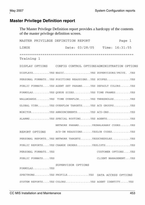
May 2007 System Configuration reports
CC MIS Installation and Maintenance 453
Master Privilege Definition report
The Master Privilege Definition report provides a hardcopy of the contents of the master privilege definition screen.
MASTER PRIVILEGE DEFINITION REPORT Page 1
LINUX Date: 03/28/05 Time: 16:31:55
=======================================================Training 1
DISPLAY OPTIONS CONFIG CONTROL OPTIONSADMINISTRATION OPTIONS
DISPLAYS..........YES BASIC................YES SUPERVISORS/PRIVS. .YES
PERSONAL FORMATS..YES POSITIONS REASSIGNS..YES SCOPES..............YES
PUBLIC FORMATS....YES AGENT SET PARAMS.....YES DEFAULT COLORS......YES
FORMULAS..........YES QUEUE SIZES..........YES TIME FRAMES.........YES
WALLBOARDS........YES TIME OVERFLOW.......YES THRESHOLDS..........YES
GLOBAL VIEW.......YES OVERFLOW TARGETS.....YES ACD GROUPS..........YES
MONITOR...........YES ANNOUNCEMENTS........YES ACD-DNS.............YES
ALARMS............YES SPECIAL ROUTING......YES AGENTS..............YES
NETWORK PARAMS........YESWALKAWAY CODES......YES
REPORT OPTIONS ACD-DN REASSIGNS......YESLOB CODES...........YES
PERSONAL REPORTS..YES NETWORK TARGETS.......YESSCHEDULES...........YES
PUBLIC REPORTS....YES CHANGE ORDERS.........YESLISTS...............YES
PERSONAL FORMATS..YES CUSTOMER OPTIONS....YES
PUBLIC FORMATS....YES CLIENT MANAGEMENT...YES
FORMULAS..........YES
SUPERVISOR OPTIONS
SPECTRUMS.........YES PROFILE.............YES DATA ACCESS OPTIONS
SYSTEM REPORTS....YES COLORS...............YES AGENT IDENTITY.....YES

System Configuration reports Standard 2.0
454 Call Center Management Information System
GLOBAL VIEW.......YES MESSAGING............YES AGENT PERFORMANCE..YES
MONITOR...........YES
NOTE: Privileges listed as NO* are not available for this partition.

CC MIS Installation and Maintenance 455
A p p e n d i x E
System Log messages
In this appendixStandard error messages . . . . . . . . . . . . . . . . . . . . . . . . . . . . . . . . . . . 456
General messages . . . . . . . . . . . . . . . . . . . . . . . . . . . . . . . . . . . . . . . . 460
MAPA messages. . . . . . . . . . . . . . . . . . . . . . . . . . . . . . . . . . . . . . . . . . 467
DMSLINK messages. . . . . . . . . . . . . . . . . . . . . . . . . . . . . . . . . . . . . . . 482
CCLINK messages . . . . . . . . . . . . . . . . . . . . . . . . . . . . . . . . . . . . . . . . 495
RPTGEN messages . . . . . . . . . . . . . . . . . . . . . . . . . . . . . . . . . . . . . . . 497
CFGDB messages . . . . . . . . . . . . . . . . . . . . . . . . . . . . . . . . . . . . . . . . 499
CFGMGR messages. . . . . . . . . . . . . . . . . . . . . . . . . . . . . . . . . . . . . . . 501
USRIF messages . . . . . . . . . . . . . . . . . . . . . . . . . . . . . . . . . . . . . . . . . 514
STSMGR messages . . . . . . . . . . . . . . . . . . . . . . . . . . . . . . . . . . . . . . . 520
CFGUTIL messages . . . . . . . . . . . . . . . . . . . . . . . . . . . . . . . . . . . . . . . 525
DMS Simulator messages. . . . . . . . . . . . . . . . . . . . . . . . . . . . . . . . . . . 531
WINSERVER messages . . . . . . . . . . . . . . . . . . . . . . . . . . . . . . . . . . . . 540
AGE messages . . . . . . . . . . . . . . . . . . . . . . . . . . . . . . . . . . . . . . . . . . . 544
BAR messages . . . . . . . . . . . . . . . . . . . . . . . . . . . . . . . . . . . . . . . . . . . 547
WALLBOARD messages . . . . . . . . . . . . . . . . . . . . . . . . . . . . . . . . . . . 551
MAINT messages . . . . . . . . . . . . . . . . . . . . . . . . . . . . . . . . . . . . . . . . . 552
SCHEDULER messages. . . . . . . . . . . . . . . . . . . . . . . . . . . . . . . . . . . . 557
DDBSERV messages . . . . . . . . . . . . . . . . . . . . . . . . . . . . . . . . . . . . . . 558

System Log messages Standard 2.0
456 Call Center Management Information System
Standard error messages
Introduction
This section contains a list of standard error messages generated by the CC MIS product. These messages can be generated by any of the subsystems of the CC MIS product. The messages can be any of the following, depending on the conditions under which these errors are generated:
informational messageswarning messagesfatal messages
Note: The CC MIS product runs on a Down Stream Processor, therefore the error messages do not appear in the switch log.
Log actions
The following log actions are the possible actions that you should perform when a log message is generated. Each log message specification indicates one or more action codes. Perform the actions in the order listed. If an action fails to resolve or determine the problem, perform the next action on the list.
The actions are:
A Possible installation problem. If the system was installed recently, reinstall system. Otherwise, contact TAS - supply complete log messages.
B Contact TAS - supply complete log messages.
C Use database Storage Calculator to readjust database storage parameters. The Storage Calculator is accessed through the Maintenance interface by selecting the configuration then data storage menu items. Additionally, the hours of operation parameters can require adjustment.

May 2007 System Log messages
CC MIS Installation and Maintenance 457
D Potential hardware or operating system failure. Contact hardware vendor with system error message and port name.
E Contact design support prior to reboot of system. Supply complete log messages.
F Possible connectivity problem to switch. Verify all connections and communication equipment between CC MIS and switch.
G Re-enable link in Maintenance Interface through Diagnostics > Switch Link Definition.
H Verify switch datafill parameters.
I Check/verify switch datafill and status of MPC/EMPC.
J No action required; normal operation of system. If problems are evident, check for other log messages.
K Check/verify MIS session status on switch.
L Potential problem only. Check other log messages carefully. If this log message occurs frequently, contact design support and supply all log messages.
M Verify consistency of Network Operation Services (NOS) logon parameters and switch datafill.
N Verify that all CC MIS partitions are configured with a valid subpool name.
O Verify that switch datafill parameters do not exceed CC MIS limits.
P Verify switch datafill parameters do not exceed database storage calculator parameters.
Q Verify switch datafill. Contact switch support.
R May be caused by excessive switch or MIS activity. Monitor for other log messages.
S Check/verify switch hardware components (IOC, MPC/EMPC).

System Log messages Standard 2.0
458 Call Center Management Information System
T Potential synchronization problem between switch and MIS. If switch datafill has been altered since last MIS re-initialization, then re-initialize MIS using the “Update Switch Configuration Data” command from the “Run State Utilities” maintenance menu.
U Check/verify report parameters.
V Verify system default printer has been defined. Verify settings in the CC MIS Supervisor Interface for customer and/or supervisor default printers.
W Consult the backup log.
X Adjust report parameters.
Y Check connectivity between CC MIS server and client software.
Z Check for compatibility of Windows interface software and CC MIS server software.
AA Consult the restore log.
AB Check CC MIS configuration.
AC Check Agent Definitions for valid APR configuration.
AD Discontinue use of the Call Park feature.
AE Verify that switch datafill uses only one login ID partition per subpool.
AF The backup did not complete and may need to be restarted and monitored.
AG The restore did not complete and the system may be in an unknown state. The restore may need to be restarted and closely monitored.
AH Deselect translation of unneeded messages and retry.
AI Check/verify configuration.

May 2007 System Log messages
CC MIS Installation and Maintenance 459
Standard log format
All log messages use the following format (note that portions within square brackets [ ] appear only when appropriate):
<message type> at <date> <time><message text>Process: <process> (<pid>)[Partition:<partition>][Instance:<instance>]Source: <module>, <function>, <line>[<other info>][<other info>]
where:
<message type> = FATAL, WARNING, EVENT <date> = current date (MM/DD/YY) <time> = current time (HH:MM:SS)<message text> = see list that follows<process> = link_read, display, hdc, and so on<pid> = UNIX process ID of the process calling log function<partition> = partition number in which the process is running<instance> = indicates which instance of a process (for processes which may have multiple invocations)<module> = module that generated the log message<function> = function that generated the log message<line> = line number within module at which error occurred<other info> = can include items such as an operating system code for operating system errors
The error message text may contain [XX], 'YYYY', or both, which denote any numeric or string, respectively.

System Log messages Standard 2.0
460 Call Center Management Information System
General messages
The following messages can be generated by any process within CC MIS.
Database read failure [xx] — table: yyyy An error occurred while reading data from the table specified in the “yyyy” field. “xx” gives the database error code. (Action Code: B)
Database write failure [xx] — table: yyyyAn error occurred while writing data to the table specified in the “yyyy” field. “xx” gives the database error code. (Action Code: B)
Database deletion failure [xx] — table: yyyy An error occurred while trying to delete a record from the table specified in the “yyyy” field. “xx” gives the database error code. (Action Code: B)
Database connect failure [xx]An error occurred while trying to connect to the database server process to perform a database operation. “xx” gives the database error code. (Action Code: B)
Database table lookup failure [xx] — table: yyyyAn error occurred while trying to obtain database structure information for the table specified in the “yyyy” field. “xx” gives the database error code. (Action Code: B)
Database record lookup failure [xx] — rectype: yyyyAn error occurred while trying to obtain database structure information for the record type specified in the “yyyy” field. “xx” gives the database error code. (Action Code: B)
May 2007 System Log messages
CC MIS Installation and Maintenance 461
Database record lookup failure [xx] — table: yyyyAn error occurred while trying to obtain database structure information for the record type used in the database table specified in the “yyyy” field. “xx” gives the database error code. (Action Code: B)
Database record count failure [xx] — table: yyyyAn error occurred while trying to obtain the count of records in the database table specified in the “yyyy” field. “xx” gives the database error code. (Action Code: B)
Database record enumeration failure [xx] — table: yyyyAn error occurred while trying to enumerate the records in the database table specified in the “yyyy” field. “xx” gives the database error code. (Action Code: B)
Database record parse failure [xx] — table: yyyyAn error occurred while trying to parse a record in the database table specified in the “yyyy” field. “xx” gives the database error code. (Action Code: B)
Connection to database server not establishedAn attempt was made to perform a database request when no connection to the database server had been established. (Action Code: B)
Failed to send request to database serverAn error occurred when attempting to send a database request message to the database server. (Action Code: B)
Failed to receive response from database serverAn error occurred when attempting to read a database response message from the database server. (Action Code: B)
Unexpected message received from database serverThe program received a message from the database server that it did not expect. (Action Code: B)

System Log messages Standard 2.0
462 Call Center Management Information System
File mapping failure — file: xxxxxFollowing a database enumeration request in which the resulting records were to be sorted, the program experienced an error attempting to map the results file named in the “xxxxx” field into its address space. (Action Code: B)
File unmapping failure — file: xxxxxFollowing a database enumeration request in which the resulting records were to be sorted, the program experienced an error attempting to unmap the results file named in the “xxxxx” field from its address space. (Action Code: B)
Language record parse error — type: xxxxxThe program encountered a language record that it was unable to parse. The type of the record being parsed is named in the “xxxxx” field. (Action Code: B)
Main record parse error — type: xxxxx, field: nnThe program encountered a main database record that it was unable to parse. The type of the record being parsed is named in the “xxxxx” field, and the field number which could not be parsed is given in the “nn” field. (Action Code: B)
Poll failedThe “poll” system call returned an error code. (Action Code: B)
I/O port open error - port: yyyyIndicates that the program was unable to open the I/O port identified by “yyyy”. The “system error” description should provide additional information as to the reason for the error. (Action Code: D)
I/O port setup error Indicates that the program was unable to properly set the communications parameters for its I/O port. The “system error” description should provide additional information as to the reason for the error. (Action Code: D)

May 2007 System Log messages
CC MIS Installation and Maintenance 463
I/O port read error Indicates that the program was unable to read from its associated I/O port. The “system error” description should provide additional information as to the reason for the error. (Action Code: D)
I/O port write errorIndicates that the program was unable to write to its associated I/O port. The “system error” description should provide additional information as to the reason for the error. (Action Code: D)
File open error - file: yyyy Indicates that the program was unable to open the file specified by “yyyy”. (Action Code: B)
Freopen error - file: yyyyIndicates that the program was unable to reopen the file specified by “yyyy”. (Action Code: B)
File create error - file: yyyyIndicates that the program was unable to create the file specified by “yyyy”. (Action Code: B)
File write error - file: yyyyIndicates that the program was unable to write to the file specified by “yyyy”. (Action Code: B)
Pipe creation error - pipe: yyyy Indicates that the program was unable to create the named pipe specified by “yyyy”. Named pipes are used for communicating between programs. (Action Code: B)
Pipe open error - pipe: yyyyIndicates that the program was unable to open the named pipe specified by “yyyy”. Named pipes are used for communicating between programs. (Action Code: B)

System Log messages Standard 2.0
464 Call Center Management Information System
Pipe write error - pipe: yyyyThe program was unable to write to the named pipe specified by “yyyy”. (Action Code: B)
Pipe read error - pipe: yyyyThe program was unable to read from the named pipe specified by “yyyy”. (Action Code: B)
Memory allocation failureThe program was unable to allocate any additional memory. (Action Code: B)
Unable to create a new processThe program was unable to create a new process. This could indicate that there are a large number of defunct or runaway processes in the system. A system reboot may alleviate the problem. (Action Code: E)
Unable to start “yyyy” programThe program was unable to start the specified program. The “system error” description should provide additional information as to the reason for the error. (Action Code: B)
yyyy environment variable not foundThe specified environment variable was not found. This indicates that the program encountering the error is being run in the wrong environment. This is a design error which should only occur during software development. (Action Code: B)
SIGHUP: Hang-up signal receivedThe process received a hang-up signal. This log message should never occur. (Action Code: B)
SIGINT: Interrupt signal receivedThe process received an interrupt signal. This log message should never occur. (Action Code: B)

May 2007 System Log messages
CC MIS Installation and Maintenance 465
SIGILL: Illegal instructionAn illegal instruction was executed by the process. This log message should never occur. However, it could be associated with memory problems, potential disk failure, or installation errors. (Action Code: A, E)
SIGFPE: Floating-point exceptionAn invalid floating point operation occurred. (Action Code: B)
SIGEMT: Unexpected signalA process received an unexpected emulation trap signal. (Action Code: B)
SIGBUS: Bus errorA bus error occurred. This is typically generated by an invalid memory pointer but may also be generated by faulty memory. (Action Code: B)
SIGSYS: Bad argument to system callA system call was executed with invalid parameters. (Action Code: B)
SIGPIPE: Write to pipe with no read processA write was issued to a IPC pipe but the reader process is no longer active. (Action Code: L)
SIGQUIT: Unexpected signalA process received an unexpected signal to quit. (Action Code: L)
SIGTERM: Process terminatedThis message is normally generated by processes as they are terminating. (Action Code: J)
SIGSEGV: Segmentation violationThis message may be generated due to an invalid memory pointer. It may also be generated due to hardware problems. (Action Code: B)
SIGIOT: IOT trapAn I/O trap was received on an input or output operation. (Action Code: B)

System Log messages Standard 2.0
466 Call Center Management Information System
SIGTRAP: Trace trapThis message is generated if processes are being traced. This signal should never occur. (Action Code: B)
Socket creation failed - type: AF_UNIX/STREAMIndicates that the program was unable to create a new socket. The “other info” line may include additional information. (Action Code: B)
Socket bind failed - socket: yyyyIndicates that the program was unable to bind the socket to the file specified by “yyyy”. (Action Code: B)
Socket listen failed - socket: yyyyIndicates that the program was unable to set the socket up as a listen socket. The “yyyy” field specifies the name of the socket. (Action Code: B)
Socket connect failed - socket: yyyyIndicates that the program was unable to connect to the listen socket specified by “yyyy”. (Action Code: B)
Socket accept failed - socket: yyyyIndicates that the program was unable to accept a connection to the listen socket specified by “yyyy”. (Action Code: B)
Lock error (nn) - lock: yyyyAn error occurred (specified by the “nn” field) getting the lock specified by “yyyy”. (Action Code: B)
File stat error - file: yyyyAn error occurred retrieving file status information on the file specified by “yyyy”. (Action Code: B)
Unexpected signal: nnAn unexpected signal was received by the process. The signal value is specified by “nn”. (Action Code: B)

May 2007 System Log messages
CC MIS Installation and Maintenance 467
MAPA messages
Introduction
This section contains the error messages generated by the MAPA subsystem of the CC MIS product.
Note: The CC MIS product runs on a Down Stream Processor, therefore the error messages do not appear in the switch log.
Informational messages
This section lists the informational messages that may be generated by the master “ccmis” process. These messages are produced as part of normal system operation to indicate the occurrence of significant events.
Clock has been synchronized to network time MAPA has completed synchronizing the time on the local node with the network time. (Action Code: J)
Node nnn (xxxxxx) is UPThe remote node whose ID and name are given by “nnn” and “xxxxxx” respectively is now operational. (Action Code: J)
Starting network time synchronization... MAPA is starting to synchronize the time on the local node with the network time. This log only appears during system start-up. (Action Code: J)
System shutdown completedMAPA has completed the orderly shutdown of the system and is exiting without error. This occurs when the system is shut down. (Action Code: J)
System startup initiatedMAPA is starting the orderly startup of the system. (Action Code: J)

System Log messages Standard 2.0
468 Call Center Management Information System
Warning messages
This section lists the warning messages that may be generated by the MAPA process. These messages usually indicate an unusual condition that can be appropriately handled by the MAPA process, and which does not prevent the MAPA process from continuing operation.
Accept failed on connection socket - type: xxxxxxMAPA was unable to accept a connection request as part of the startup of a connection-oriented service. The “xxxxxx” field indicates either AF_UNIX or AF_INET depending on whether the connection request was internal or external respectively. (Action Code: B)
Accept failed on socket for “xxxxxx” portMAPA was unable to accept a connection request on the TCP port whose logical name is given by the “xxxxxx” field. Currently, these ports are used for establishing connections from LAN connected supervisor workstations but their use may be expanded in future releases. The name of the port gives an indication of the type of service that is provided by that port. MAPA will attempt to correct the problem by re-creating the socket for this port.(Action Code: L)
Asked to add client xxxxxx to unknown partition “nnn”The system attempted to register the LAN-connected PC whose IP address is given by “xxxxxx” against the partition whose ID is given by “nnn”. (Action Code: B)
Asked to add client xxxxxx to unknown port “xxxxxx”The system attempted to register the LAN-connected PC whose IP address is given by “xxxxxx” against an unknown TCP port named “xxxxxx”. (Action Code: B)
Asked to add duplicate node ID “nnn”A request was made to add a network node to the system using a node ID that is already in use. (Action Code: L)

May 2007 System Log messages
CC MIS Installation and Maintenance 469
Asked to add duplicate node address “xxxxxx”A request was made to add a network node to the system using a node address that is already in use. (Action Code: L)
Asked to add service for unknown program “xxxxxx”MAPA was requested to begin monitoring a program whose name (given by “xxxxxx”) is unknown to MAPA. (Action Code: B)
Asked to change maximum on lock in unknown partition “nnn”A request was received to change the maximum for a lock in a unknown partition. The unknown partition ID is given by “nnn” in the log message. (Action Code: B)
Asked to change maximum on unknown lock “nnn:xxxxxx”A request was received to change the maximum for an unknown partition/lock combination. The “nnn:xxxxxx” field in the log message specifies the partition ID and lock name. (Action Code: B)
Asked to delete all clients in unknown partition “nnn”A request was received to delete all IP address registrations against the partition whose ID is given by “nnn”. (Action Code: B)
Asked to delete local nodeA network node deletion request was received which specified the local node as the node to be deleted. (Action Code: B)
Asked to delete unknown node ID “nnn” A network node deletion request was received which specified an unknown node to be deleted. (Action Code: L)
Asked to delete unknown partition “nnn”A partition deletion request was received for a unknown partition. (Action Code: L)

System Log messages Standard 2.0
470 Call Center Management Information System
Asked to disable networking for unknown partition “nnn”A request was received to disable networking for an unknown partition. (Action Code: B)
Asked to enable networking for unknown partition “nnn” A request was received to enable networking for an unknown partition. (Action Code: B)
Asked to lock “xxxxxx” in unknown partition “nnn”A lock request was received to lock the “xxxxxx” resource in an unknown partition whose ID is given by “nnn”. (Action Code: B)
Asked to register xxxxxx “nnn” against unknown partition “ppp”A request was received to register an IPC object against an unknown partition. The IPC object being registered is identified by:
xxxxxx — Specifies the type of IPC object, where SHMID identifies a shared memory segment, SEMID identifies a semaphore, and MSGID identifies a message queue.nnn — Specifies the ID number of the IPC object.
(Action Code: B)
Asked to run “xxxxxx” in inactive partition “nnn”A request was received to run program “xxxxxx” in a partition which is currently in the stopped state. (Action Code: L)
Asked to run “xxxxxx” in unknown partition “nnn”A request was received to run program “xxxxxx” in a partition which is unknown. (Action Code: L)
Asked to run “xxxxxx” on unknown node “nnn”A request was received to run program “xxxxxx” on a node which is unknown. (Action Code: L)

May 2007 System Log messages
CC MIS Installation and Maintenance 471
Asked to set environment for unknown partition “nnn”A request was received to set an environment variable in a unknown partition. (Action Code: B)
Asked to set process limit for unknown class “xxxxxx”A request was received to change the process limit for an unknown transient program class. (Action Code: L)
Asked to set process limit for unknown partition “nnn”A request was received to change a transient process limit for an unknown partition. (Action Code: L)
Asked to start unknown partition “nnn”A request was received to start an unknown partition. (Action Code: L)
Asked to start unknown program “xxxxxx”A request was received to start an unknown program. The name of the program is identified by “xxxxxx”. (Action Code: L)
Asked to stop unknown partition “nnn”A request was received to stop an unknown partition. (Action Code: L)
Asked to unlock “xxxxxx” in unknown partition “nnn”A request was received to unlock the resource identified by “xxxxxx” in an unknown partition. (Action Code: L)
Clock synchronization failed MAPA was unable to set the local system clock to the average network time. (Action Code: B)
Connection timeout expiredA timeout occurred while creating the connection for a connection-oriented service. (Action Code: B)

System Log messages Standard 2.0
472 Call Center Management Information System
Dependent program “nnn” not found for program “xxxxxx”The program description for the program named “xxxxxx” specifies that it is dependent on an unknown program whose program number is given by “nnn”. (Action Code: B)
Environment space exhausted for partition “nnn”There is no more space available for storing private environment variables for the partition whose number is “nnn”. (Action Code: B)
Error reading service ID from connection socket - bytes=nA request for a connection-oriented service has failed because the complete service ID (4 bytes long) could not be read from the connection socket. MAPA was able to read only “n” bytes of the service ID. (Action Code: B)
Failed to kill program xxxxxx (nnn)MAPA was unable to kill the program named “xxxxxx” and process ID is “nnn”. (Action Code: L)
Failed to set RT priority - pid: ppp, priority: nnnMAPA was unable to set a real-time priority for the process whose process ID is given by “ppp”. The requested real-time priority value was “nnn”. (Action Code: B)
Failed to set TS priority - pid: nnn, priority: nnnMAPA was unable to set a time-sharing priority for the process whose process ID is given by “ppp”. The requested time-sharing priority value was “nnn”. (Action Code: B)
Halt request received - shutdown startingA halt request was received. MAPA is proceeding with graceful system shutdown. (Action Code: J)
Lock “nnn:xxxxxx” is unknownA lock request was received for an unknown lock. “nnn:xxxxxx” is the partition number and name of the unknown lock. (Action Code: B)

May 2007 System Log messages
CC MIS Installation and Maintenance 473
MAPA message queue found in IPC registryIndicates that MAPA found its own message queue identifier in the list of message queues to be deleted upon program or partition termination. MAPA automatically removes this object from the list.(Action Code: L)
MAPA shared memory found in IPC registryIndicates that MAPA found its own shared memory segment identifier in the list of shared memory segments to be deleted upon program or partition termination. MAPA automatically removes this object from the list. (Action Code: L)
Network response timeout - message type: xxxxxx No response was received within the allotted timeout period for a message sent to a remote node. The type of message is “xxxxxx”. (Action Code: B)
No network time available - using nodal time Indicates that MAPA was unable to find any other nodes on the network during system startup and is therefore using the current time of the system instead of setting the system time to the average time of all other nodes on the network. (Action Code: J)
No object type in IPC register request from process nnnThe type of Inter-Process Communication (IPC) object was not specified in an IPC object registration request. “nnn” is the process ID of the program which sent the request. (Action Code: B)
Nodal time adjustment failed MAPA was unable to make an adjustment to the nodal time to bring it in line with the network time. (Action Code: B)
Node nnn (xxxxxx) not responding A node in the network is not responding to messages sent to it. “nnn” is the node ID number and “xxxxxx” is the node name. (Action Code: L)

System Log messages Standard 2.0
474 Call Center Management Information System
Node table is full No more node table slots are available for a new node. (Action Code: B)
Partition “nnn” already existsA request was received to create a partition which already exists. (Action Code: L)
Program “nnn (xxxxxx)” asked to kill unknown service “[nnn.]PPP.ppppp”MAPA received a request to kill a program that it does not know about. The program is identified by a two- or three-part identifier as follows:
nnn — Specifies the node ID on which the program is running. This part of the identifier does not appear if the program is on the local node.PPP — Identifies the partition ID in which the program is running.ppppp — Identifies the Unix process ID of the program.
(Action Code: B)
Program “nnn (xxxxxx)” attempted to register MAPA message queueThe identified program asked MAPA to register MAPA’s own message queue for deletion upon program or partition termination. “xxxxxx” and “nnn” is the name and process ID of the program making the request. (Action Code: L)
Program “nnn (xxxxxx)” attempted to register MAPA shared memoryThe identified program asked MAPA to register MAPA’s own shared memory segment for deletion upon program or partition termination. “xxxxxx” and “nnn” is the name and process ID of the program making the request. (Action Code: L)
Partition table is fullNo more partition table slots are available for a new partition. (Action Code: B)

May 2007 System Log messages
CC MIS Installation and Maintenance 475
Partition type “xxxxxx” not foundA request was received to create a partition of a type that is not known. “xxxxxx” is the invalid partition type. (Action Code: B)
Program xxxxxx (nnn) aborted: ddddddddddddddddThe program specified has aborted abnormally. “xxxxxx” and “nnn” is the name and process ID of the aborted program, and “dddddddddddddddd” is the description of the abort cause. (Action Code: B)
Program xxxxxx (nnn) is deadThe program specified has died. xxxxxx= program name, (nnn)= programs process ID. (Action Code: B)
Program xxxxxx (nnn) is insaneThe program specified was declared insane and will be killed by MAPA. xxxxxx= program name, (nnn)= programs process ID. (Action Code: B)
Program table is fullNo more program table slots are available for a new program instance. (Action Code: B)
Received “xxxxxx” from unrecognized program “nnn (pppppp)”The message xxxxxx was received from an unrecognized program with process ID of (nnn) and program name of (pppppp). (Action Code: L)
Remote program xxxxxx (nnn.PPP.ppppp) is insane A program started on a remote node in the network has been declared insane and will by killed by MAPA. “xxxxxx” is the name of the program and “nnn.PPP.ppppp” is the program service ID as follows:
nnn — Specifies the node ID on which the program is running.PPP — Identifies the partition ID in which the program is running.ppppp — Identifies the Unix process ID of the program.
(Action Code: B)

System Log messages Standard 2.0
476 Call Center Management Information System
Service addition request from unknown program “nnn”A request was received to register an already running process with MAPA but the process sending the request is unknown to MAPA. (Action Code: B)
Socket receive failed MAPA was unable to receive a message from a remote node.(Action Code: B)
Socket send failed MAPA was unable to send a message to a remote node. (Action Code: B)
Unable to bind address for xxxxxx stream socketMAPA was unable to bind an address to the stream socket whose type is given by “xxxxxx”. The “xxxxxx” field indicates either AF_UNIX or AF_INET depending on whether the socket is for internal or external communication respectively. (Action Code: B)
Unable to bind address for message socket MAPA was unable to bind an address to the message socket used to communicate with other nodes in the network. (Action Code: B)
Unable to create xxxxxx stream socketMAPA was unable to create a stream socket whose type is given by “xxxxxx”. The “xxxxxx” field indicates either AF_UNIX or AF_INET depending on whether the socket is for internal or external communication respectively. (Action Code: B)
Unable to create listen queue for stream socketThe queue used to listen for requests on a stream socket could not be created. (Action Code: B)
Unable to create message socket MAPA was unable to create the message socket used to communicate with other nodes in the network. (Action Code: B)

May 2007 System Log messages
CC MIS Installation and Maintenance 477
Unable to determine ID of priority class “xx”MAPA was unable to determine the numeric ID of the priority class given by “xx”. “xx” is either “TS” for the time-sharing priority class, or “RT” for the real-time priority class. (Action Code: B)
Unable to set system timeA failure occurred trying to set a new system time. (Action Code: B)
Unauthorized connection attempt on port “xxxxxx” from nnn.nnn.nnn.nnnA connection attempt was received on the TCP port whose name is given by “xxxxxx” from an IP address which is not authorized to connect to this system. The IP address of the unauthorized user is given by “nnn.nnn.nnn.nnn”. (Action Code: AB)
Unexpected acknowledgment for message type nnn, txid=xxx An acknowledgment message was received which was not expected. The type and transaction ID of the message being acknowledged is given by the “nnn” and “xxx” fields respectively. (Action Code: B)
Unknown message type “xxx” received from “nnn”Mapa received a message which it is not able to parse. (Action Code: B)
Unknown service ID “xxxxxx” in SRVC_BEGUN message A remote node has indicated that it has started a service on behalf of the local node that the local node is not aware of. (Action Code: B)
Unknown service ID “xxxxxx” in connection requestA request for a connection-oriented service has failed because the service ID read from the connection socket could not be found in the program table. (Action Code: B)

System Log messages Standard 2.0
478 Call Center Management Information System
Fatal error messages
Fatal error messages are generated by MAPA in response to conditions which prevent the process from continuing normal execution. This section lists these error messages.
Directory “xxxxxx” does not existA change directory command failed to find the specified directory. (Action Code: B)
Entry nnn in LOCKS section has invalid lock typeThe file which describes the software configuration of the system contains an invalid instruction. Specifically, an invalid lock type was specified for item number “nnn” in the LOCKS section of the file. (Action Code: B)
Entry nnn in LOCKS section is invalidThe file which describes the software configuration of the system contains an invalid instruction. Specifically, item number “nnn” in the LOCKS section of the file could not be parsed. (Action Code: B)
Entry nnn in PARTITIONS section is invalidThe file which describes the software configuration of the system contains an invalid instruction. Specifically, item number “nnn” in the PARTITIONS section of the file could not be parsed. (Action Code: B)
Entry nnn in PORTS section is invalidThe file which describes the software configuration of the system contains an invalid instruction. Specifically, item number “nnn” in the PORTS section of the file could not be parsed. (Action Code: B)
Entry nnn in PROGRAMS section has invalid classThe file which describes the software configuration of the system contains an invalid instruction. Specifically, an invalid program class was specified in item number “nnn” in the PROGRAMS section of the file. (Action Code: B)

May 2007 System Log messages
CC MIS Installation and Maintenance 479
Entry nnn in PROGRAMS section has invalid transient program classThe file which describes the software configuration of the system contains an invalid instruction. Specifically, an invalid transient program class was specified in item number “nnn” in the PROGRAMS section of the file. (Action Code: B)
Entry nnn in PROGRAMS section is invalidThe file which describes the software configuration of the system contains an invalid instruction. Specifically, item number “nnn” in the PROGRAMS section of the file could not be parsed. (Action Code: B)
Entry nnn in XPROG_CLASSES section is invalidThe file which describes the software configuration of the system contains an invalid instruction. Specifically, item number “nnn” in the XPROG_CLASSES section of the file could not be parsed.(Action Code: B)
Failed to re-create connection socket - type: xxxxxxThe attempt to recreate a connection socket in an attempt to recover from an earlier “Socket accept failure” has failed. (Action Code: B)
Invalid tag “xxxxxx” in GENERAL section of config fileThe file which describes the software configuration of the system contains an invalid instruction. Specifically, an invalid parameter name was found in the GENERAL section of the file. (Action Code: B)
Invalid section name “xxxxxx” in configuration fileThe file which describes the software configuration of the system contains an invalid instruction. Specifically, an invalid section was found in the file. (Action Code: B)
Lock table is fullThe lock table has become full. No more locks could be created. (Action Code: B)

System Log messages Standard 2.0
480 Call Center Management Information System
Message receive failed - queue ID: nnnMessage queue read failed for some reason other than no messages in queue. “nnn” is the message queue identifier of the MAPA message queue. (Action Code: B)
Message send failed - queue ID: nnn, msgtype: ttt, pid: pppMessage queue send failed for some reason other than message queue was full. The message queue identifier on which the send was attempted is given by “nnn”. The type of message being sent was “ttt” and the process to which it was being sent was “ppp”. (Action Code: B)
Missing -c <configuration file> argumentMAPA was invoked without the -c argument which tells it the file name of its configuration file. (Action Code: B)
Missing section in configuration fileThe file which describes the software configuration of the system is missing a required section. (Action Code: B)
No partitions definedNo partitions were defined in the software configuration file. (Action Code: B)
No programs definedNo programs were defined in the software configuration file.(Action Code: B)
Partition table is fullToo many partition types were specified in the software configuration file. (Action Code: B)
Port table is fullToo many TCP ports were specified in the software configuration file. (Action Code: B)

May 2007 System Log messages
CC MIS Installation and Maintenance 481
Program table is fullToo many programs were specified in the software configuration file. (Action Code: B)
Record nnn in physical node table is invalid Record number “nnn” in the physical node table which describes the nodes in the network could not be parsed. (Action Code: B)
Transient program class table is fullThe file which describes the software configuration of the system contains an invalid instruction. Specifically, too many transient program classes were defined. (Action Code: B)
Unknown program “xxxxxx” associated with TCP port ppppppThe file which describes the software configuration of the system contains an invalid instruction. Specifically, the program used to service a request on the TCP port named “pppppp” was not described in the PROGRAMS section of the configuration file. (Action Code: B)

System Log messages Standard 2.0
482 Call Center Management Information System
DMSLINK messages
Introduction
This section contains the error message generated by the DMSLINK subsystem of the CC MIS product.
Note: The CC MIS product runs on a Down Stream Processor, therefore the error messages do not appear in the switch log.
Informational messages
The following messages do not indicate an error condition but are used as notification of significant events which occur as part of normal operation.
Call data transfer beginning...The switch has acknowledged the request to begin transferring call event data. (Action Code: J)
Connected to switch <ip_addr:port>The CC MIS system has successfully connected to the switch identified by the given IP address and port number. (Action Code: J)
End of initialization data download...The switch has completed the initialization data download. (Action Code: J)
Initialization data download beginning...The switch has responded to the request to send initialization data and is about to start the initialization data download. (Action Code: J)
Initiating a nosLogon...DMSLINK is sending a nosLogon request to the switch. (Action Code: J)

May 2007 System Log messages
CC MIS Installation and Maintenance 483
Initiating a nosLogout...DMSLINK is sending a nosLogout request to the switch. (Action Code: J)
LINK TRACING IS NOW OFFLink messages in both directions are now being logged to the link data trace file. (Action Code: J)
LINK TRACING IS NOW ONLink message tracing has been turned off and the trace file has been closed. (Action Code: J)
Requesting initialization...DMSLINK is requesting initialization data from the switch. (Action Code: J)
Requesting start of call data transfer...DMSLINK is requesting the switch to begin sending call event data. (Action Code: J)
Warning messages This section lists the warning messages that may be generated by the DMSLINK process. These messages usually indicate an unusual condition that can be appropriately handled by the DMSLINK process, and which does not prevent the DMSLINK process from continuing execution.
<ro type> is not a valid operation at this timeA Remote Operation (RO) of type <ro type> was received from the switch at a time that was not appropriate (for example, an initialization data RO was received when no dspRequestInit request has been issued). (Action Code: F, K, B)

System Log messages Standard 2.0
484 Call Center Management Information System
ACD group <primary dn> associated with unknown subpool number nnA switchSendAcdGroupData message was received from the switch that referenced a subpool for which CC MIS has not received a switchSendSubPoolData message for. (Action Code: F, R)
ACD group configuration overflow errorThe merging of newly received initialization data with configuration information obtained from a previous initialization sequence has resulted in too many ACD groups in the configuration. This indicates a software problem in the CC MIS system. (Action Code: B)
ACD-DN configuration overflow errorThe merging of newly received initialization data with configuration information obtained from a previous initialization sequence has resulted in too many ACD-DNs in the configuration. This indicates a software problem in the CC MIS system. (Action Code: B)
Accept failedA request to accept a new application connection to this DMSLINK process has failed.(Action Code: B)
Already Logged on - Logging offIn attempting to log on to the switch, it was discovered that the switch believes the DSP is already logged on. The DSP now requests a logoff and restarts the logon sequence. (Action Code: L)
Application resource shortage error - type: nnnThe switch is reporting an application resource shortage error of a type that is not recognized by the DSP. 'nn' gives the unrecognized reason code contained in the error message. No action is taken by DMSLINK other than reporting the error. (Action Code: Q)

May 2007 System Log messages
CC MIS Installation and Maintenance 485
Associate request received for unknown subpool “<subpool name>”DMSLINK received a request from another process to associate itself with a subpool that is not in the configuration information received from the switch. (Action Code: N)
Bad value in RO: rrrrrrr, field: ffffff, value: vvvvv An illegal value has been detected in an RO received from the switch. “rrrrrr” identifies the type of RO, “ffffff” gives the field within the RO, and “vvvvv” gives the illegal value. DMSLINK attempts to continue regardless of the error. (Action Code: S, B)
Data receive local failure on <LAN>An error occurred while attempting to read data from the TCP/IP switch link. (Action Code: AC, F, B)
Dump in progress - LM request deniedThis error indicates that a DMS image is currently being taken and all load management requests will be rejected. This error condition is passed back to the CCLINK process in the response to its request. (Action Code: J)
Error message received for unknown invoke ID nnnDMSLINK received a ReturnError message from the switch for an Invoke message that DMSLINK does not believe to be outstanding to the switch. (Action Code: L)
Hard limit of nnn ACD groups reachedIndicates that more than “nnn” unique ACD groups exist in the ACD pool to which the CC MIS has been associated. All further ACD groups will be silently discarded. The ACD group limit is determined from the options configured on the software load tape. (Action Code: O)

System Log messages Standard 2.0
486 Call Center Management Information System
Hard limit of nnnn ACD-DNs reachedIndicates that more than “nnnn” unique ACD-DNs exist in the ACD pool to which the CC MIS has been associated. All further ACD-DNs are silently discarded. The ACD-DN limit is determined from the options configured on the software load tape (17 x number of ACD groups configured). (Action Code: O)
Hard limit of nnnn positions reachedIndicates that more than “nnnn” unique position IDs exist in the ACD pool to which the CC MIS has been associated. All further position IDs will be silently discarded. The position limit is determined from the options configured on the software load tape. (Action Code: O)
Hard limit of nnnn subgroups reachedIndicates that more than “nnnn” unique subgroups exist in the ACD pool to which the CC MIS has been associated. All further subgroups will be silently discarded. The subgroup limit is determined from the options configured on the software load tape (number of positions configured / 2). (Action Code: O)
Hard limit of nnn subpools reachedIndicates that more than “nnn” unique subpools exist in the ACD pool to which the CC MIS has been associated. All further subpools will be silently discarded. The subgroup limit is currently set to 128. (Action Code: O)
Illegal message type xx received on OOB pipeDMSLINK received an unrecognized message on the out-of-band events pipe from the simulator. The illegal message type is given by the 'xx' field in the error message. This message is simply ignored. (Action Code: L)
Illegal message type [nn] received from applicationAn illegal message type was received by DMSLINK from another CC MIS application. The message will be ignored. (Action Code: B)

May 2007 System Log messages
CC MIS Installation and Maintenance 487
Invalid argument error - type: nn The switch is reporting an invalid argument error of a type that is not recognized by the DSP. 'nn' gives the unrecognized reason code contained in the error message. No action is taken by DMSLINK other than reporting the error. (Action Code: L)
Invalid arguments passed - ignored The DMSLINK process has been invoked with invalid arguments. The invalid arguments have been ignored. (Action Code: B)
Invalid NOP protocol versionThe switch has rejected a log on request because the NOP protocol version requested by the DSP is invalid. (Action Code: I)
Invalid line in initialization fileAt least one invalid line was found in the initialization file. (Action Code: B)
Invalid subpool password - LM request deniedA load management request has been denied because the subpool password as read from the configuration database does not match the password datafilled on the switch for the specified subpool. This error condition is passed back to the CCLINK process in the response to its request. (Action Code: M)
LINK TRACE FILE SIZE LIMIT REACHEDThe link trace data file for this link has reached its maximum file size. Link data tracing has been terminated. (Action Code: J)
Lost connection to switchDMSLINK has lost communication with the switch. (Action Code: L, F)
Lost synchronization on input data streamDMSLINK has lost synchronization on the input data stream and will attempt to resynchronize. (Action Code: L)

System Log messages Standard 2.0
488 Call Center Management Information System
No Remote Load Management processThe switch could not create the Remote Load Management process to service a load management request from the DSP. This error condition is passed back to the CCLINK process in the response to its request. (Action Code: Q)
No buffers availableThe switch has run out of buffer space for ACD-MIS ROs. No action is taken by DMSLINK other than reporting the error. (Action Code: Q)
Non-control message received on unassociated socketAn application program has sent a non-control message on a socket connection to DMSLINK before it has associated itself with a particular subpool. (Action Code: B)
Operation sequence error - type: nnThe switch is reporting an operation sequence error of a type that is not recognized by the DSP. 'nn' gives the unrecognized reason code contained in the error message. No action is taken by DMSLINK other than reporting the error. (Action Code: L)
Pool already associated - Logging offThe pool with which the DSP is attempting to associate itself is already associated with another DSP. DMSLINK will initiate a logoff sequence before terminating itself. (Action Code: M, Q)
Position nnnn unexpectedly moved to another ACD groupAn event message was received for position “nnnn” which indicates that it is now in an ACD group which is different from the ACD group that the CC MIS system believes it to be in. This could be caused by lost messages on the X.25 link. (Action Code: F)

May 2007 System Log messages
CC MIS Installation and Maintenance 489
Position configuration overflow errorThe merging of newly received initialization data with configuration information obtained from a previous initialization sequence has resulted in too many positions in the configuration. This indicates a software problem in the CC MIS system. (Action Code: B)
Posn nnnn moved with call active: ssssssssss -> ddddddddddThe CC MIS system has determined that position “nnnn” was moved via load management with an ACD call active. The ACD group in which the call was answered is given by “ssssssssss” and the new ACD group is given by “dddddddddd”. Call timings will be split between the two ACD groups with all call time after the time of the error message being logged against the new ACD group. (Action Code: J)
Posn nnnn moved with call presented: ssssssssss -> ddddddddddThe CC MIS system has determined that position “nnnn” was moved via load management with an ACD call presented to the agent. The ACD group in which the call was originally received is given by “ssssssssss” and the new ACD group is given by “dddddddddd”. All statistics for this call will be logged against the new ACD group. (Action Code: J)
RO rejected by DSP - type: tttttttt, code: cccccccA badly formatted RO was received by the DSP and has been rejected. The “tttttt” field identifies the type problem encountered (General, Invoke, ReturnResult, or ReturnError) and the “cccccc” field provides the specific problem code. The hexadecimal dump of the received message will follow in the error log. (Action Code: M, B, Q)
RO rejected by switch - type: tttttttt, code: cccccccThe switch rejected an RO sent by DMSLINK. The “tttttt” field identifies the type problem encountered (General, Invoke, ReturnResult, or ReturnError) and the “cccccc” field provides the specific problem code. (Action Code: M, B)

System Log messages Standard 2.0
490 Call Center Management Information System
Reject message received for unknown invoke ID nnnDMSLINK received a Reject message from the switch for an Invoke message that DMSLINK does not believe to be outstanding to the switch. (Action Code: L)
Response timeout on <ro type> request - retrying...DMSLINK has not received a response from the switch for the message whose type is given by <ro type>. DMSLINK will retry the request up to three times before giving up and re-establishing the link. (Action Code: L)
Result message received for unknown invoke ID nnnDMSLINK received a return result for an invoke message numbered “nnn” which does not appear to have been generated by CC MIS. (Action Code: Q)
Searching for a link...Connection attempts have failed on all links to the switch. DMSLINK continues to attempt to establish a connection. (Action Code: F, I, S)
Simulator process has diedThe simulator process for this link has died. DMSLINK will automatically restart it. (Action Code: B)
Subgroup configuration overflow errorThe merging of newly received initialization data with configuration information obtained from a previous initialization sequence has resulted in too many subgroups in the configuration. This indicates a software problem in the CC MIS system. (Action Code: B)
Subpool nnn is using the “Call Park” featureDMSLINK has determined that the “Call Park” feature is being used in subpool number “nnn”. Use of this feature is not supported by CC MIS and causes invalid statistics to be gathered. (Action Code: AD)

May 2007 System Log messages
CC MIS Installation and Maintenance 491
Subpool nnn uses multiple (mmm) login ID partitionsDMSLINK has determined that the multiple login ID partitions are being used in subpool number “nnn”. This will cause statistics for the same agent IDs in different login ID partitions to be accumulated under the same agent ID in the CC MIS historical database. (Action Code: AD)
Subpool configuration overflow errorThe merging of newly received initialization data with configuration information obtained from a previous initialization sequence has resulted in too many subpools in the configuration. This indicates a software problem in the CC MIS system. (Action Code: B)
Switch is running a different NOP protocol version (xxxxx)The switch is running a protocol version than is that being used by DMSLINK. Some messages may fail when DMSLINK attempts to decode them. (Action Code: M)
Switch not responding...terminating sessionIndicates that a message has been retransmitted to the switch the maximum number of times without receiving a response. DMSLINK is now terminating the existing session with the switch and will attempt to re-establish it. (Action Code: F)
Synchronization regained after skipping nnn bytesDMSLINK has regained synchronization on the input data stream from the switch after skipping over “nnn” bytes of data. Some data has been lost. (Action Code: F)
System problem error - type: nnThe switch is reporting a system problem error of a type that is not recognized by the DSP. 'nn' gives the unrecognized reason code contained in the error message. No action is taken by DMSLINK other than reporting the error. (Action Code: Q)

System Log messages Standard 2.0
492 Call Center Management Information System
Time changed backwardsThe system clock has been changed backwards. Historical data accumulated around the time of this error log should not be trusted. (Action Code: B)
Too many ROs outstanding from DSPThe switch has indicated that it currently has too many unprocessed Remote Operations outstanding to be able to process the one just sent by the DMSLINK process. This error would indicate a problem with the switch because DMSLINK does not allow more outstanding ROs to be sent to the switch than can be handled by the switch according to the ACD-MIS protocol specification. No action is taken by DMSLINK other than reporting the error. (Action Code: Q)
Updating physical link configurationDMSLINK has been notified of a potential change in the status of its X.25 port. This log appears when the “X.25 Diagnostics” screen is used to disable or enable an X.25 link. (Action Code: J)
Value range error in non-LM requestThe switch is reporting a value range error in a request that is not a load management request. No action is taken by DMSLINK other than reporting this error. For LM request messages encountering a value range error, this error condition is passed back to the CCLINK process for appropriate handling. (Action Code: L)
Fatal error messages
Fatal error messages are generated by DMSLINK in response to conditions which prevent the process from continuing normal execution. This section lists these error messages.
ACD pool protocol “xxxxx” is not supportedThe ACD pool protocol datafilled on the switch for this link is invalid. (Action Code: Q)

May 2007 System Log messages
CC MIS Installation and Maintenance 493
Data transmit local failure on <LAN>An error occurred while attempting to write data to the switch link. (Action Code: F, B)
Invalid parameter [c] in initialization fileAn invalid parameter was found in the initialization file. The invalid parameter is identified by “[c]” in the error message. (Action Code: B)
Invalid pool passwordThe password for the pool as read from the system database does not match the password datafilled on the switch for the pool. (Action Code: M)
Invalid pool protocolThe switch is not running the correct protocol version. (Action Code: M)
Maximum logons exceededThe switch has disallowed the DSP's request to log on because it already has the maximum number of simultaneous logons in progress. (Action Code: K, S)
Missing parameter in initialization fileAt least one parameter is missing from the initialization file specified by the “-f” option used to invoke the DMSLINK process. (Action Code: B)
Unable to open startup file: xxxxxxDMSLINK was unable to open the startup configuration file specified by the “-f” option used to invoke the DMSLINK process. (Action Code: B)
Unable to start ACDMIS application on switchThe switch is returning an invalid argument error stating that it does not recognize the application ID. (Action Code: Q)
Unable to start simulator processDMSLINK was unable to start the simulator process for a simulated link. (Action Code: B)

System Log messages Standard 2.0
494 Call Center Management Information System
Undefined pool nameThe pool name as read from the system database does not match any ACD pool datafilled on the switch. (Action Code: M)
User ID or password is invalidThe user ID or password as read from the system database does not agree with any user ID/password combination programmed on the switch. The request for the start-up of the ACD-MIS application has been denied. (Action Code: M)
Wrong switch state for requestThe switch is indicating that it is in the wrong state to accept a request from the DSP. To re-synchronize the switch and the DSP, DMSLINK will initiate a logoff/logon sequence followed by a re-initialization. (Action Code: Q)

May 2007 System Log messages
CC MIS Installation and Maintenance 495
CCLINK messages
Introduction
This section lists the error/warning messages that may be generated by CCLINK. These messages usually indicate an unusual condition that has occurred within CC MIS software.
Warning error messages
This section lists the warning messages that may be generated by the CCLINK process. These messages usually indicate an unusual condition that can be appropriately handled by the CCLINK process, and which does not prevent the CCLINK process from continuing execution.
Invalid CC message receivedCCLINK received an unknown message. (Action Code: B)
Configuration Control transaction log is corruptedThe Configuration Control transaction log has become corrupted. (Action Code: B)
Switch connection abortedThe switch aborted its connection. (Action Code: B)
Switch connection has aborted; retrying...The switch has aborted its connection, CCLink is attempting to reconnect. (Action Code: B)
Unable to send LM command to switchThe switch did not accept the load management command. (Action Code: B)

System Log messages Standard 2.0
496 Call Center Management Information System
Fatal error messages
Fatal error messages are generated by CCLINK in response to conditions which prevent the process from continuing normal execution. This section lists the error message.
Subpool yyyy on link nnnn does not existThe subpool yyyy does not exist on link nnnn. (Action Code: H)

May 2007 System Log messages
CC MIS Installation and Maintenance 497
RPTGEN messages
Introduction
This section contains the error message generated by the RPTGEN subsystem of the CC MIS product.
Note: The CC MIS product runs on a Down Stream Processor, therefore the error messages do not appear in the switch log.
Warning messages
This section lists the warning messages that may be generated by the RPTGEN process. These messages usually indicate an unusual condition that can be appropriately handled by the RPTGEN process, and which does not prevent the RPTGEN process from continuing execution.
Unable to print: rptgen tabular outputA failure was received from the call to print_job. (Action Code: L)
Unable to print: rptgen eventlog output A failure was returned by the call to print_job. (Action Code: L)
Unable to lock DATA databaseRPTGEN was unable to obtain a lock on the data database. (Action Code: L)
Unable to unlock DATA database RPTGEN was unable to release the lock on the data database. (Action Code: L)

System Log messages Standard 2.0
498 Call Center Management Information System
The following errors are all warning messages dealing with file close and file unlink errors. These errors occur when the system calls fclose and unlink return bad return codes. (Action Code: B)
Unable to close file: stdout. Unable to unlink graphic report intermediate file. Unable to close file: graphic preview file. Unable to close graphic report intermediate file.
Fatal error messages
Fatal error messages are generated by RPTGEN in response to conditions which prevent the process from continuing normal execution. This section lists these error messages.
Unable to read file: graphic report intermediate file A system call to fgets returned a bad return code. (Action Code: B)
Invalid report number requestedA report was requested that doesn’t exist. (Action Code: U)
Unable to find delimiter characterDisplay was unable to find the delimiter character, and is therefore unable to print the report. (Action Code: B)

May 2007 System Log messages
CC MIS Installation and Maintenance 499
CFGDB messages
Introduction
This section contains the error messages generated by the CFGDB subsystem of the CC MIS product.
Note: The CC MIS product runs on a Down Stream Processor, therefore the error messages do not appear in the switch log.
Warning messages
This section lists the warning messages that may be generated by the CFGDB process. These messages usually indicate an unusual condition that can be appropriately handled by the CFGDB process, and which does not prevent the CFGDB process from continuing execution. Although not fatal, many of these warnings indicate a serious condition that may require attention.
Unable to lock configuration databaseAn error occurred trying to lock the configuration database. (Action Code: B)
Unable to obtain CONFDB read lockAn error occurred trying to obtain a read lock on the configuration database. (Action Code: B)
Unable to obtain CONFDB write lockAn error occurred trying to obtain a write lock on the configuration database. (Action Code: B)
Unable to unlock configuration databaseAn error occurred trying to unlock the configuration database. (Action Code: B)

System Log messages Standard 2.0
500 Call Center Management Information System
Fatal error messages
Fatal error messages are generated by CFGDB in response to conditions which prevent the process from continuing normal execution. This section lists these error messages.
Options file read errorAn error occurred trying to read the global options file. (Action Code: B)
Unable to determine my customer ID numberAn error occurred trying to determine the partition ID from the environment. (Action Code: B)
Error parsing record in yyyyAn error occurred trying to parse a record in the specified file. (Action Code: B)
File seek error - file: yyyyAn error occurred trying to seek to a location in the specified file. (Action Code: B)
File stat failure - file: yyyyAn error occurred trying to stat the specified file. (Action Code: B)
File tell error - file: yyyyAn error occurred trying to perform an ftell on the specified file. (Action Code: B)

May 2007 System Log messages
CC MIS Installation and Maintenance 501
CFGMGR messages
Introduction
This section contains the error messages generated by the CFGMGR subsystem of the CC MIS product.
Note: The CC MIS product runs on a Down Stream Processor, therefore the error messages do not appear in the switch log.
Warning messages
This section lists the warning messages that may be generated by the CFGMGR process. These messages usually indicate an unusual condition that can be appropriately handled by the CFGMGR process, and which does not prevent the CFGMGR process from continuing execution. Although not fatal, many of these warnings indicate a serious condition that may require attention.
Could not flush message bufferAn error occurred trying to flush the message buffer. (Action Code: B)
Could not make socket non-blockingAn error occurred trying to make a socket non-blocking. (Action Code: B)
Could not write message to cfgmgrAn error occurred trying to write a message to the cfgmgr. (Action Code: B)
COMPORTS table access failure (rc = xxxx)An error occurred trying to access the COMPORTS database table. (Action Code: B)
CUST_INFO table access failed for custID xxxx (rc = xxxx)An error occurred trying to access the CUST_INFO database table. (Action Code: B)

System Log messages Standard 2.0
502 Call Center Management Information System
CUST_INFO table access failed for partition xxxxAn error occurred trying to access the CUST_INFO database table. (Action Code: B)
CUST_INFO table access failure (rc = xxxx)An error occurred trying to access the CUST_INFO database table.
(Action Code: B)
CUST_INFO update fails for partition xxxx after move (rc = xxxx)An error occurred trying to access the COMPORTS database table. (Action Code: B)
Cannot use link number xxxx (max is xxxx)The specified link number is greater than the maximum number of links allowed. (Action Code: B)
Could not add partition xxxxAn error occurred trying to add the specified partition. (Action Code: B)
Could not allocate disk xxxx for partition xxxxAn error occurred trying to add the specified disk for the specified partition. (Action Code: B)
Could not calculate free space on disk xxxxAn error occurred trying to calculate the free space on the specified disk. (Action Code: B)
Could not determine move completion status for partition xxxxAn error occurred trying to determine the move completion status for the specified partition. (Action Code: B)
Could not reset reinit time for link xxxxAn error occurred trying to reset the reinitialization time for the specified partition. (Action Code: B)

May 2007 System Log messages
CC MIS Installation and Maintenance 503
Could not restart partition xxxx after the moveAn error occurred trying to restart the specified partition after it was moved. (Action Code: B)
Could not transition partition xxxx to correct modeAn error occurred trying to transition the specified partition to the correct mode. (Action Code: B)
Failed to remove data database for partition xxxxAn error occurred trying to remove the data database for the specified partition. (Action Code: B)
Failed to send move acknowledgment to PID xxxxAn error occurred trying to send the move acknowledgment to the specified process ID. (Action Code: B)
Failed to set up system database for partition xxxxAn error occurred trying to set up the system database for the specified partition. (Action Code: B)
Insufficient space on disk to change partition size to xxxx megsAn error occurred trying to set up the system database for the specified partition. (Action Code: B)
Insufficient space to add partition xxxx to diskNum xxxxThere is insufficient space to add the specified partition to the specified disk. (Action Code: B)
Invalid message type (xxxx)An invalid message was received. (Action Code: B)
LANCONNECTS table access failure (rc = xxxx)Unable to access record in the LANCONNECTS table. (Action Code: B)
LINK_DEF Table access failure (rc = xxxx)Unable to access record in the LINK_DEF table. (Action Code: B)

System Log messages Standard 2.0
504 Call Center Management Information System
No further move processing will be performed for partition xxxxNo further move processing will occur for the specified partition due to an error trying to determine the move completion status. (Action Code: B)
Port xxxx not found in PortTblThe specified port was not found in the port table. (Action Code: B)
Service execution for “age -c” fails (rc = xxxx)An error occurred trying to execute “age -c”. (Action Code: B)
cfgmgr socket interface not initializedThe cfgmgr socket interface is not initialized. (Action Code: B)
client_add fails for partition xxxx, IP yyyy, mistext (rc = xxxx)An error occurred trying to add a text based LAN client. (Action Code: B)
client_add fails for partition xxxx, IP yyyy, miswindows (rc = xxxx)An error occurred trying to add a windows based LAN client.(Action Code: B)
client_delete fails for IP yyyy, mistext (rc = xxxx)An error occurred trying to delete a text based LAN client. (Action Code: B)
client_delete fails for IP yyyy, miswindows (rc = xxxx)An error occurred trying to delete a windows based LAN client.(Action Code: B)
could not de-register yyyy shared memory segment with MAPA (rc = xxxx)An error occurred trying to de-register a shared memory segment with MAPA. (Action Code: B)

May 2007 System Log messages
CC MIS Installation and Maintenance 505
could not register yyyy shared memory segment with MAPA (rc = xxxx)An error occurred trying to register a shared memory segment with MAPA. (Action Code: B)
could no restart partition xxxx after mode changeAn error occurred trying to restart the specified partition after a mode change. (Action Code: B)
could not stop partition xxxx to change modesAn error occurred trying to stop the specified partition so that a mode change could be performed. (Action Code: B)
partition xxxx must be assigned a disk to change modesThe partition must be assigned a disk before changing modem.(Action Code: AI)
partition ID xxxx out of range [1..xxxx]The specified partition ID is out of range. (Action Code: B)
partition_delete fails for partition xxxx (rc = xxxx)An error occurred trying to delete the specified partition. (Action Code: B)
received delete message for unknown partition “xxxx”A delete message was received for an unknown partition. (Action Code: B)
request_service fails for program yyyy (rc = xxxx)A request_service failed for the specified program. (Action Code: B)
CUST_INFO access failure (partition=xxxx; rc=xxxx)Unable to access record in the CUST_INFO table. (Action Code: B)
Cannot start partition xxxx in SETUP modeCannot start a partition in SETUP mode. (Action Code: AI)
System Log messages Standard 2.0
506 Call Center Management Information System
DBSTORAGE table access failure (rc = xxxx)Unable to access record in the DBSTORAGE table. (Action Code: B)
DBSTORAGE table not initialized for partition xxxxThe DBSTORAGE table is not initialized for the specified partition.(Action Code: B)
LINK_DEF table access failure (linkNum=xxxx; rc=xxxx)Unable to access record in the LINK_DEF table. (Action Code: B)
Link number xxxx not foundThe specified link number was not found. (Action Code: B)
Live type link required to start partition xxxx in product modeYou must have a live link to start a partition in product mode. (Action Code: AI)
No more partitions using a live link may be started (max = xxxx)The maximum number of live partitions has already been reached. (Action Code: AI)
No subpool name defined for partition xxxxThere is no subpool name defined for the specified partition. (Action Code: AI)
No subpool password defined for partition xxxxThere is no subpool password defined for the specified partition. (Action Code: AI)
STOREPARMS table access failure (custID = xxxx, rc = xxxx)Unable to access record in the STOREPARMS table. (Action Code: B)
Simulator type link required to start partition xxxx in training modeYou must have a simulator link to start a partition in training mode. (Action Code: AI)

May 2007 System Log messages
CC MIS Installation and Maintenance 507
invalid partition mode (partition=xxxx; mode=xxxx)The partition has an invalid mode. (Action Code: B)
no disk selected for partition xxxxThere is no disk selected for the specified partition. (Action Code: B)
no link selected for partition xxxxThere is no link selected for the specified partition. (Action Code: B)
partition number xxx out of rangeThe partition number is out of range. (Action Code: B)
Could not flush message bufferAn error occurred trying to flush the message buffer. (Action Code: B)
Could not make socket non-blockingAn error occurred trying to make the socket non-blocking. (Action Code: B)
Unrecognized message xxxx received from xxxxAn unrecognized message is received. (Action Code: B)
cfgmgr closing socket to cfgutil (cfgutil PID = xxxx)An error occurred closing the socket to the cfgutil process. (Action Code: B)
completion acknowledgment fails (type = xxxx, sequence = xxxx)An error occurred trying to send a completion acknowledgment. (Action Code: B)
lost connection with clientThe connection was lost with the client. (Action Code: B)
message acknowledgment fails (type = xxxx, sequence = xxxx)An error occurred trying to send a message acknowledgment. (Action Code: B)

System Log messages Standard 2.0
508 Call Center Management Information System
socket read errorA socket read error occurred. (Action Code: B)
COMPORTS table access failureUnable to access record in the COMPORTS table. (Action Code: B)
CUST_INFO table access failure (custID = xxxx; rc = xxxx)Unable to access record in the CUST_INFO table. (Action Code: B)
Could not create ager signal file “yyyy”An error occurred trying to create the ager signal file. (Action Code: B)
DBSTORAGE table access failureUnable to access record in the DBSTORAGE table. (Action Code: B)
DISKS table access failure (diskNum = xxxx; rc = xxxx)Unable to access record in the DISKS table. (Action Code: B)
Error xxxx deleting from DBSTORAGE tableThe specified error occurred trying to delete a record from the DBSTORAGE table. (Action Code: B)
Error xxxx deleting record yyyy from LANCONNECTS tableThe specified error occurred trying to delete a record from the LANCONNECTS table. (Action Code: B)
Error xxxx deleting record (key xxxx) from CUST_INFO tableThe specified error occurred trying to delete a record from the CUST_INFO table. (Action Code: B)
Error xxxx deleting record (key xxxx) from CUST_OPTIONS tableThe specified error occurred trying to delete a record from the CUST_OPTIONS table. (Action Code: B)

May 2007 System Log messages
CC MIS Installation and Maintenance 509
Error xxxx deleting record (key xxxx) from STOREPARMS tableThe specified error occurred trying to delete a record from the STOREPARMS table. (Action Code: B)
Error xxxx deleting record (key xxxx) from WALLBOARDS tableThe specified error occurred trying to delete a record from the WALLBOARDS table. (Action Code: B)
LANCONNECTS table access failureUnable to access record in the LANCONNECTS table. (Action Code: B)
PRINTERS table access failureUnable to access record in the PRINTERS table. (Action Code: B)
WALLBOARDS table access failureUnable to access record in the WALLBOARDS table. (Action Code: B)
COMPORTS table access failure (rc = xxxx)Unable to access record in the COMPORTS table. (Action Code: B)
CUST_INFO table access failure (custID = xxxx; rc = xxxx)Unable to access record in the CUST_INFO table. (Action Code: B)
CUST_OPTIONS table access failure (custID = xxxx; rc = xxxx)Unable to access record in the CUST_OPTIONS table. (Action Code: B)
Cannot initialize partition xxxxUnable to initialize the specified partition. (Action Code: B)
Creation of partition xxxx fails (rc = xxxx)Unable to create the specified partition. (Action Code: B)
DISKS table access failure (diskNum = xxxx; rc = xxxx)Unable to access record in the DISKS table. (Action Code: B)

System Log messages Standard 2.0
510 Call Center Management Information System
Failed to set partition limit for partition xxxx (rc = xxxx)An error occurred trying to set the limits for the specified partition. (Action Code: B)
LANCONNECTS tale access failure (rc = xxxx)Unable to access record in the LANCONNECTS table. (Action Code: B)
LINK_DEF table access failure (rc = xxxx)Unable to access record in the LINK_DEF table. (Action Code: B)
client_add fails (yyyy, xxxx, mistext)Unable to add a text based LAN client. (Action Code: B)
client_add fails (yyyy, xxxx, miswindows)Unable to add a windows based LAN client. (Action Code: B)
get_partition_state fails for partition xxxxUnable to determine the state of the specified partition. (Action Code: B)
Error occurred communicating with MAPAUnable to report initialization to MAPA. (Action Code: B)
STDTbl entry not foundUnable to find the service ID entry in the service ID table. (Action Code: B)
Cannot start partition xxxxError trying to start the specified partition. (Action code: B)
Configuration problem for partition xxxxThere is a configuration problem with the specified partition. (Action Code: B)
Failed to retrieve CUST_INFO record for partition xxxx (rc = xxxx)Error trying to retrieve a record from the CUST_INFO table for the specified partition. (Action Code: B)

May 2007 System Log messages
CC MIS Installation and Maintenance 511
Failed to retrieve LINK_DEF record (xxxx) for partition xxxx (rc = xxxx)Error trying to retrieve a record from the LINK_DEF table for the specified partition. (Action Code: B)
Unable to start partition xxxxError trying to start the specified partition. (Action Code: B)
Unable to stop partition xxxxError trying to stop the specified partition. (Action Code: B)
request_service fails for “yyyy” (rc = xxxx)Request service failed for the specified service. (Action Code: B)
SID table size consistency errorThere is an inconsistency in the size of the service ID table. (Action Code: B)
lan clients table size consistency errorThere is an inconsistency in the size of the lan clients table. (Action Code: B)
link table size consistency errorThere is an inconsistency in the size of the link table. (Action Code: B)
Caught SIGCHLD from death of unknown process (PID = xxxx)The SIGCHLD signal was received from the death of an unknown process. (Action Code: B)
Could not create ager signal file “yyyy”Error trying to create the ager signal file. (Action Code: B)
Could not make directory “yyyy”Error trying to create the specified directory. (Action Code: B)

System Log messages Standard 2.0
512 Call Center Management Information System
More than xxxx wallboards defined on port xxxxThere are more than the specified number of wallboards defined on the port. (Action Code: B)
Re-initialization response error occurred for link xxxxA re-initialization response error occurred for the specified link. (Action Code: B)
SIGTERM: process terminatedThe SIGTERM signal was received. (Action Code: J)
Unable to connect to link xxxxError trying to connect to the specified link. (Action Code: B)
cfgdb: error xxxx reading yyyy tableAn error occurred trying to read the specified table. (Action Code: B)
non-implemented error message class (xxxx)An unrecognized error return value was received. (Action Code: B)
Unknown hard ID (xxxx) received on wallboard commands pipeAn unknown wallboard hard ID was received. (Action Code: B)
Informational messages
The following messages do not actually indicate an error condition but are used as notification of significant events that occur as part of normal operation.
caught SIGUSR1: updating internal state tablesReceived the SIGUSR1 signal after a backup occurred indicating that the internal state tables will be updated. (Action Code: L)
caught SIGUSR2: reinitialization static language shared memoryCFGMGR received a signal to reload the static language shared memory segment. (Action Code: L)

May 2007 System Log messages
CC MIS Installation and Maintenance 513
Move of partition xxxx beginningThe move of the specified partition has started. (Action Code: J)
Move of partition xxxx failedThe move of the specified partition has failed. (Action Code: B)
Move of partition xxxx successfulThe move of the specified partition was successful. (Action Code: J)
Fatal error messages
Fatal error messages are generated by CFGMGR in response to conditions which prevent the process from continuing normal execution. This section lists the error message.
Unable to communicate with MAPAError trying to communicate with MAPA while trying to (re)start programs. (Action Code: B)

System Log messages Standard 2.0
514 Call Center Management Information System
USRIF messages
Introduction
This section contains the error messages generated by the USRIF subsystem of the CC MIS product. USRIF writes the messages to its 'Standard Error' device. The error messages may contain [XX] and/or 'YYYY', which denote any numeric and/or string, respectively.
Warning messages
This section lists the warning messages that may be generated by the USRIF subsystem. These messages usually indicate an unusual condition that can be appropriately handled by the process, and which does not prevent the process from continuing execution.
Too many help screens. Help will appear out of sync with current screen. Help screens have nested too deeply (beyond MAX_STACK_TAGS-1). When this occurs, the additional levels are ignored. The visible effect of this is help text that does not match the screen where help is being sought.(Action Code: B)
No '=' found in keyboard description entry Entry in <term>.KD file is improperly formatted. (Action Code: B)
No terminating '\' found for keyboard label A key translation specification in the <term>.KD file contains only the name of the key. (Action Code: B)
Keystroke sequence missing The sequence of characters sent from the keyboard for this key is missing from the <term>.KD file. (Action Code: B)

May 2007 System Log messages
CC MIS Installation and Maintenance 515
Logical function key definition is missing The key translation sequence for a required key is missing. (Action Code: B)
Periodic function list is full An attempt to add another function to the list of functions periodically activated while awaiting keyboard input has failed because the list is full. (Action Code: B)
Invalid window number A request was made to redraw a non-existent window. (Action Code: B)
Window does not correspond to a menu Request made to redraw a window that is not a menu. (Action Code: B)
Failed to determine spool pipe status Was unable to determine status of the pipe serving the print spooler.(Action Code: B)
Bad ACDTERMCAP parameter: missing '#' for numeric parameterThe specification for a numeric parameter in the ACDTERMCAP file is missing a required number sign (#). (Action Code: B)
Bad ACDTERMCAP parameter: string parameter lacks '='The specification for a string parameter in the ACDTERMCAP file is missing a required equal sign (=). (Action Code: B)
Bad ACDTERMCAP parameter: Illegal escape character Only a character from the set Eenlrtbfs^\,;01234567 can be escaped using the backslash. (Action Code: B)
No '=' found in video attribute entry The entry in the <term>.VA file is improperly formatted. (Action Code: B)
Invalid attribute name in video attribute file Unknown attribute name specified in <term>.VA file. (Action Code: B)
System Log messages Standard 2.0
516 Call Center Management Information System
Duplicate video attribute Video specification has already been defined in <term>.VA file. (Action Code: B)
Logical video attribute definition is missing One of the video attributes was not defined for the selected terminal type. (Action Code: B)
No '=' found in special character entry The entry in the <term>.SC file is improperly formatted. (Action Code: B)
Logical character code is invalid The internal character code is not within the range of 1 to 254.(Action Code: B)
Physical character code is invalid The external character code is not within the range of 1 to 254. (Action Code: B)
Unable to open special character file Either the <term>.SC file couldn't be located or its access rights prohibited read access. (Action Code: B)
Table form has not yet been created Attempt to animate a table form that has not been created. (Action Code: B)
Invalid character following '^' In <term>.VA file, character being control-shifted is not in the set of @, A-Z, a-z, [, \, ], ^, or _. (Action Code: B)
Invalid token Token being converted is not an octal number. (Action Code: B)
Value of token exceeds 377 octal The token's value as specified in the <term>.VA file exceeds 377 octal. (Action Code: B)

May 2007 System Log messages
CC MIS Installation and Maintenance 517
Missing definition for video attributeA definition for a video attribute is missing. (Action Code: AI)
Invalid monochrome attribute specificationAn invalid monochrome attribute was specified. (Action Code: AI)
Missing foreground color specificationA foreground color specification is missing. (Action Code: AI)
Missing background color specificationA background color specification is missing. (Action Code: AI)
Invalid foreground color specificationAn invalid foreground color was specified. (Action Code: AI)
Invalid background color specificationAn invalid background color was specified. (Action Code: AI)
Fatal error messages
Fatal error messages are generated by USRIF in response to conditions that prevent the process from continuing normal execution. This section lists these error messages.
Cannot acquire memory from system There exists an insufficient amount of system memory to create the key handling information tables. (Action Code: B)
Invalid logical key name in keyboard file In initializing key translation specifications in the <term>.KD file, an unknown key name has been encountered. (Action Code: B)
Pathname of keyboard description file is unknown No kF entry, usually in the form of kF=<term>.KD, was specified in the product termcap file. (Action Code: B)

System Log messages Standard 2.0
518 Call Center Management Information System
Unable to open keyboard description file Either the <term>.KD file could not be found or read access was not allowed. (Action Code: B)
Error reading keyboard description file Though the <term>.KD file was found and read access was available, an error occurred while reading the file. (Action Code: B)
Unable to create error message virtual screen Attempt to create the one-line error dialog window on the bottom of the screen was unsuccessful. (Action Code: B)
Keyboard description file is empty The <term>.KD file contained no properly formatted key translation specifications. (Action Code: B)
Menu does not contain any menu items Request was made to create a menu that has no items defined. (Action Code: B)
Unable to open ACD-MIS termcap fileThe file defined by environment variable ACDTERMCAP could not be found or its access rights prohibited reading it. (Action Code: B)
Pathname of video attributes file is unknown The aF entry in the ACDTERMCAP file was not specified. (Action Code: B)
Unable to open video attributes file The aF entry in the ACDTERMCAP file was given incorrectly such that the video attributes file can not be found. (Action Code: B)
Error reading video attributes file Though the <term>.VA file could be found and had read access rights available, an error occurred in reading the file. (Action Code: B)

May 2007 System Log messages
CC MIS Installation and Maintenance 519
Error reading special characters file Though the <term>.SC file was located and allowed read access, an error occurred during reading it. (Action Code: B)
Could not set terminal into raw mode Attempt to reset standard input parameters failed. (Action Code: B)
Non-contiguous CELL array This error indicates that the DSP's memory allocation for c types char and byte are not equal. (Action Code: B)
Too many virtual screens The number of defined virtual screens has reached its maximum number. (Action Code: B)
Too many windows The number of defined windows has reached its maximum number.(Action Code: B)
Number of windows is inconsistent The window counter indicates that at least one window slot should be available, but the window number array is full. (Action Code: B)
No entry found in ACDTERMCAP file for yyyyThe specified term setting is not valid, or is not supported.(Action Code: AI)
Memory allocation failureThe process was unable to allocate enough memory. (Action Code: B)

System Log messages Standard 2.0
520 Call Center Management Information System
STSMGR messages
Introduction
This section contains the error messages generated by the STSMGR subsystem of the CC MIS product.
The error messages may contain [XX] and/or 'YYYY', which denote any numeric and/or string, respectively.
Warning messages
This section lists the warning messages that may be generated by the STSMGR process. These messages usually indicate an unusual condition that can be appropriately handled by the process, and which does not prevent the process from continuing execution.
Maximum number of ACD groups (nnn) exceeded Initialization data has been received for more than the maximum number of ACD groups. “nnn” specifies the current maximum. (Action Code: O)
Maximum number of positions (nnn) exceeded Initialization data has been received for more than the maximum number of agent positions. “nnn” specifies the current maximum. (Action Code: O)
Maximum number of supervisors (nnn) exceeded Initialization data has been received for more than the maximum number of supervisor positions. “nnn” specifies the current maximum. (Action Code: O)
Can’t get Database LockSTSMGR Manager was unable to acquire the database lock. (Action Code: L)

May 2007 System Log messages
CC MIS Installation and Maintenance 521
Database is full. No further records are being saved.The database has reached its maximum size, and can no longer save data. (Action Code: C)
Database open error: “yyyy” : yyyyThe STSMGR process was unable to open the ACDDN statistics interval file. File name “yyyy” with database error yyyy. (Action Code: B)
Errors dumping to “yyyy” : xxxx OK, XXXX BADWhen dumping yyyy, STSMGR was able to write xxxx records, and was unable to write XXXX records. (Action Code: B)
Request for AGE -c failedSTSMGR was unable to call age -c. (Action Code: B)
Request for aging failedThe request for database aging failed. (Action Code: B)
Unable to lock data database for writingSTSMGR was unable to establish a lock on the data database to enable writing. (Action Code: B)
Unable to unlock data databaseSTSMGR was unable to unlock the data database. (Action Code: B)
VFG xxxx is used in xxxx ACD groupsThe VFG entry xxxx is used in more than one ACD groups. (Action Code: B)
Connection to link has been terminatedThe DMSLINK process that STSMGR was connected to died. (Action Code: L)
Invalid command line argument - ignoredAn invalid command line argument was specified. (Action Code: B)

System Log messages Standard 2.0
522 Call Center Management Information System
Request for aging failedThe STSMGR request for aging failed. (Action Code: B)
***Call duration less than zeroThe call duration time was less than zero. (Action Code:)
Error [xxxx] moving agent [xxxx] into assigned APR subgroup [xxxx]An error occurred while trying to move an agent into their assigned APR subgroup. (Action Code: I)
Error [xxxx] returning position [xxxx] to prior subgroup [xxxx]An error occurred trying to return position xxxx to its prior subgroup xxxx. (Action Code: I)
Error [xxxx] sending request assign agent [xxxx] to assigned APR subgroup [xxxx]An error occurred while attempting to request a move agent. (Action Code: I)
Error [xxxx] sending request to return position [xxxx] to prior subgroup [xxxx]An error occurred. (Action Code: I)
Sample duration [xxxx seconds] exceeds sample intervalThe calculated duration of a real-time statistics sample exceeds the configured sample interval of 2 seconds (possibly due to a performance bottleneck on the server). (Action Code: R)
Error reading partition optionsAn error occurred while trying to read the partition options. (Action Code: B)
ACD stat duration less than zeroThe ACD stat duration is less than zero. (Action Code: R)

May 2007 System Log messages
CC MIS Installation and Maintenance 523
DN Call duration less than zeroA DN call duration was less than zero. (Action Code: R)
Invalid APR subgroup [xxxx] configured for agent [xxxx]An invalid APR subgroup is configured for agent xxxx. (Action Code: AC)
Fatal error messages
Fatal error messages are generated by STSMGR in response to conditions which prevent the process from continuing normal execution. This section lists these error messages.
Can’t get database storage limitSTSMGR was unable to determine the database storage limit. (Action Code: B)
Subpool yyyy on link xxxx does not existThe subpool yyyy on link xxxx does not exist. (Action Code: AI)
STOREPARMS table access failed (rc = xxxx)STSMGR encountered an error while trying to access the storage parameters. (Action Code: B)
Informational messages
The following messages do not actually indicate an error condition but are used as notification of significant events which occur as part of normal operation.
Transitioning to Daylight Savings TimeThe STSMGR process has switched to Daylight Savings Time. (Action Code: J)
Transitioning to Standard TimeThe STSMGR process has switched to standard time. (Action Code: J)

System Log messages Standard 2.0
524 Call Center Management Information System
AGE request has been issuedAn AGE request has been issued. (Action Code: J)
AGE -c request has been issuedAn AGE -c request has been issued. (Action Code: J)
Closing ACDDN statistics interval fileOccurs when the storage parameters are updated. (Action Code: J)
Closing LOB statistics interval fileOccurs when the storage parameters are updated. (Action Code: J)
Closing Walkaway statistics interval fileOccurs when the storage parameters are updated. (Action Code: J)
Database is no longer full. Records will now be savedThe Database now has space to add new records. (Action Code: J)
Opening ACDDN statistics interval fileOccurs when the storage parameters are updated. (Action Code: J)
Opening LOB statistics interval fileOccurs when the storage parameters are updated. (Action Code: J)
Opening Walkaway statistics interval fileOccurs when the storage parameters are updated. (Action Code: J)
Storing LOB data by groupOccurs when data is changed from store by agent to store by group. (Action Code: J)

May 2007 System Log messages
CC MIS Installation and Maintenance 525
CFGUTIL messages
Introduction
This section contains the error messages generated by the CFGUTIL subsystem of the CC MIS product. The error messages may contain [XX] and/or 'YYYY', which denote any numeric and/or string, respectively.
Warning messages
This section lists the warning messages that may be generated by the CFGUTIL process. These messages usually indicate an unusual condition that can be appropriately handled by the process, and which does not prevent the process from continuing execution.
CUST_OPTS table access failure (custID=xx; rc=xx)Error reading CUST_OPTS database table. (Action Code: B)
DBSTORAGE table access failure (rc = xxxx)Error reading DBSTORAGE database table. (Action Code: B)
DBSTORAGE table not initialized for partition xxDBSTORAGE database table not initialized properly for this partition. (Action Code: B)
Error reading configuration data baseAn error occurred trying to read from the configuration database.(Action Code: B)
Error creating SWXIF socketError trying to communicate withe the DMSLINK process.(Action Code: B)

System Log messages Standard 2.0
526 Call Center Management Information System
Cannot decrease size limit below disk required in storage calc (xxxx mb)Size limit must be greater than or equal to disk required in Storage Calculator. (Action Code: AI)
Not enough space availableNot enough room on the disk for the partition. (Action Code: AI)
Error getting partition runstateError determining the state of the partition. (Action Code: B)
Error deleting LANCONNECTS entry for yyyyError deleting database record in LANCONNECTS table. (Action Code: B)
Error updating LANCONNECTS entry for yyyyError updating database record in LANCONNECTS table. (Action Code: B)
Error deleting printer entryAn error occurred while trying to delete the printer defined on the LAN client. (Action Code: B)
Error from sigaction() while setting SIG_IGN of SIGPIPEError trying to set ignore option on SIGPIPE signal. (Action Code: B)
Error locking lock fileAn error occurred trying to open the lock file. (Action Code: B)
Error opening lock fileAn error occurred trying to open the lock file. (Action Code: B)
Error reading ptn_moving fileAn error occurred trying to determine if a partition is moving.(Action Code: B)

May 2007 System Log messages
CC MIS Installation and Maintenance 527
Error updating configuration databaseAn error occurred trying to update the configuration database. (Action Code: B)
Error adding partitionError adding a partition to the system. (Action Code: B)
Error changing mode of partitionError changing the mode of a partition. (Action Code: B)
Operation failedAn error occurred while trying to update the switch links. (Action Code: B)
Unable to read customer options fileAn error occurred trying to read the customer options file. (Action Code: B)
Unable to open yyyy fileAn error occurred trying to open the specified file. (Action Code: B)
Unable to read yyyy fileAn error occurred trying to read from the specified file. (Action Code: B)
Error changing runstate for partition xxxxAn error occurred changing the state of the specified partition.(Action Code: B)
Error disabling all changesAn error occurred trying to disable changes to all partitions.(Action Code: B)
Error enabling all changesAn error occurred trying to enable changes to all partitions. (Action Code: B)

System Log messages Standard 2.0
528 Call Center Management Information System
Error getting runstate for partition xxAn error occurred determining the state of the specified partition. (Action Code: B)
Unable to get operation result from CfgMgrUnsuccessful in receiving a response from the Configuration Manager. (Action Code: B)
Error getting partition runstateAn error occurred trying to determine the state of a partition. (Action Code: B)
Error starting partition(s)An error occurred trying to start the partition. (Action Code: B)
Error stopping partition(s)An error occurred trying to stop the partition. (Action Code: B)
Operation successfulOperation requested was performed successfully. (Action Code: J)
Operation failedOperation requested failed. (Action Code: B)
Changes disabled on a partition basisChanges are disabled for a particular partition. (Action Code: J)
Partitions in SETUP mode may not be startedTrying to start a partition in SETUP mode failed. (Action Code: AI)
A SIMULATOR type link is required for this operationOperation requires a simulator link. (Action Code: AI)
A LIVE type link is required for this operationOperation requires a live link. (Action Code: AI)

May 2007 System Log messages
CC MIS Installation and Maintenance 529
Database access failure occurredError accessing database. (Action Code: B)
An internal system error occurredInternal system error. (Action Code: B)
Partition ID out of valid rangeAn operation was requested for a partition ID that is out of range. (Action Code: B)
No disk selected for this partition dataThe partition has no disk defined. (Action Code: AI)
Database not properly initializedThe database is not properly initialized. (Action Code: B)
A subpool name is requiredA subpool name is required for the requested operation to be performed successfully. (Action Code: AI)
A subpool password is requiredA subpool password is required for the requested operation to be performed successfully. (Action Code: AI)
The maximum number of live partitions are already runningAttempting to start a partition when the maximum number of live partitions are already running. (Action Code: B)
Cannot start a partition that is not installedAttempting to start a partition that is not properly configured in the database. (Action Code: B)
Could not stop this running partitionError trying to stop partition. (Action Code: B)

System Log messages Standard 2.0
530 Call Center Management Information System
MAPA could not start this partitionMAPA encountered an error trying to start specified partition. (Action Code: B)
Fatal error messages
Fatal error messages are generated by MPSA in response to conditions which prevent the process from continuing normal execution. This section lists these error messages.
List error detectedInternal storage error detected. (Action Code: B)
Invalid arguments passedInvalid arguments were passed to the CFGUTIL program. (Action Code: B)
Error calculating required storageAn error occurred while trying to calculate the required storage. Action Code: B)
Error changing storage parametersAn error occurred trying to update the configuration database.(Action Code: B)

May 2007 System Log messages
CC MIS Installation and Maintenance 531
DMS Simulator messages
Introduction
This section contains the error messages generated by the DMS Simulator. Note that these messages only appear when the CC MIS system is in Training mode.
The error messages may contain [XX] and/or 'YYYY', which denote any numeric and/or string, respectively.
Warning messages
This section lists the warning messages that may be generated by the DMS Simulator. These messages usually indicate an unusual condition that can be appropriately handled by the process, and which does not prevent the process from continuing execution.
call_q->length = xxxx Attempted to read first call in an empty queue. (Action Code: L)
Directory number xxxxxxxxxx not found - call discarded Called number could not be found. (Action Code: L)
Invalid position No matching position ID found for the reassign position request. (Action Code: L)
RO rejected by simulator Invalid RO received by DMSSIM. (Action Code: B)
RO rejected by DSP This error message is sent any time the DSP rejects an RO. (Action Code: B)

System Log messages Standard 2.0
532 Call Center Management Information System
Unable to decode NOP message - HEX dump follows Unable to decode an incoming OPDU. (Action Code: B)
Lost synchronization on input data stream Lost synchronization while reading OPDUs in input data stream. (Action Code: B)
List Error: Appending NULL data Attempt made to append null data to doubly linked list. (Action Code: B)
List Error: Appending linked data Attempt made to append previously linked data to doubly linked list. (Action Code: B)
List Error: Inserting NULL data Attempt made to insert null data into doubly linked list. (Action Code: B)
List Error: Inserting linked data Attempt made to insert previously linked data into doubly linked list. (Action Code: B)
List Error: Deleting unlinked data Attempt made to delete previously linked data from doubly linked list. (Action Code: B)
Illegal message type xx DMSSIM received an unrecognized message. (Action Code: B)
Invalid Argument Error: [xx]An OPDU was received of this type with code [xx]. (Action Code: B)
OPDU: Invalid Argument Error: [xx]An OPDU was received of this type with code [xx]. (Action Code: B)
Operation Sequence Error: [xx] An OPDU was received of this type with code [xx]. (Action Code: B)

May 2007 System Log messages
CC MIS Installation and Maintenance 533
OPDU: Operation Sequence Error: [xx]An OPDU was received of this type with code [xx]. (Action Code: B)
Application Resource Shortage Error: [xx]An OPDU was received of this type with code [xx]. (Action Code: B)
OPDU: Application Resource Shortage Error: [xx]An OPDU was received of this type with code [xx]. (Action Code: B)
System Problem Error: [xx]An OPDU was received of this type with code [xx]. (Action Code: B)
OPDU: System Problem Error: [xx]An OPDU was received of this type with code [xx]. (Action Code: B)

System Log messages Standard 2.0
534 Call Center Management Information System
Command Error: Call Profile <yyyy> not found
Command Error: Invalid Call Queue <xxxx>
Command Error: Invalid Call Rate <xxxx>
Command Error: Invalid Group ACDDN <yyyy>
Command Error: Invalid VFG index <xxxx>
Command Error: Invalid number of agents <xxxx>
Command Error: Position ID <xxxx> out of range
Command Error: Unknown Position ID <xxxx>
Command Error: Unknown Position event <xxxx>
Command Error Walk/LOB/Agent code <xxxx> out of range
Error on application connection socket <xxxx>
Illegal Command message type <xxxx>
Illegal Control message type <xxxx>
Illegal Loadmgmt message type <xxxx>
Illegal Response message type <xxxx>
Illegal message type <xxxx>
LoadMGMT Error: Cannot reassign ACDDN <yyyy> to new subpool
LoadMGMT Error: Invalid ACDDN <yyyy>

May 2007 System Log messages
CC MIS Installation and Maintenance 535
LoadMGMT Error: Invalid ACDDN Line Priority <xxxx>
LoadMGMT Error: Invalid ACDDN Trunk Priority <xxxx>
LoadMGMT Error: Invalid ACDDN priority <xxxx>
LoadMGMT Error: Invalid Active State <xxxx>
LoadMGMT Error: Invalid Agent ID <xxxx>
LoadMGMT Error: Invalid Agent ID range <xxxx> to <xxxx>
LoadMGMT Error: Invalid Audio Index <xxxx>
LoadMGMT Error: CIF Route <xxxx>
LoadMGMT Error: Call Transfer Queue Size <xxxx>
LoadMGMT Error: FIAudio group <xxxx>
LoadMGMT Error: FOAudio group <xxxx>
LoadMGMT Error: Invalid Feature CHG_ACTIVATECHG_DWRPTIMECHG_FIAUDIO_GROUPCHG_FOAUDIO_GROUPCHG_MSQSTYPECHG_ORGANNCHG_TMDTHRTECHG_TMDTHRTE_TIME

System Log messages Standard 2.0
536 Call Center Management Information System
LoadMGMT Error: Invalid Group ACDDN <xxxx>
LoadMGMT Error: Invalid Number of Overflow Groups <xxxx>
LoadMGMT Error: Invalid Line of Business Code <xxxx>
LoadMGMT Error: Invalid MSQS Threshold type <xxxx>
LoadMGMT Error: Invalid MSQS Threshold Value <xxxx>
LoadMGMT Error: Invalid Threshold Sequence
LoadMGMT Error: Invalid Maximum CQ Size <xxxx>
LoadMGMT Error: Invalid Maximum Logical Queue Size <xxxx>
LoadMGMT Error: Invalid Maximum Queue Threshold <xxxx>
LoadMGMT Error: Invalid Maximum Wait <xxxx>
LoadMGMT Error: Invalid NSAudio group <xxxx>
LoadMGMT Error: Invalid Nite Service Route <xxxx>
LoadMGMT Error: Invalid ORGANN value <xxxx>
LoadMGMT Error: Invalid Overflow Group ACDDN <yyyy>
LoadMGMT Error: Invalid Overflow Start value <xxxx>
LoadMGMT Error: Invalid Overflow Type value <xxxx>
LoadMGMT Error: Invalid Preference Weight Factor <xxxx>
LoadMGMT Error: Invalid Priority Promotion time <xxxx>
LoadMGMT Error: Invalid RI Factor <xxxx>

May 2007 System Log messages
CC MIS Installation and Maintenance 537
LoadMGMT Error: Invalid Recorded Announcement <xxxx>
LoadMGMT Error: Invalid Service value <xxxx>
LoadMGMT Error: Invalid Subpool number <xxxx>
LoadMGMT Error: Invalid Threshold Route <xxxx>
LoadMGMT Error: Invalid Time Delay Overflow Threshold value <xxxx>
LoadMGMT Error: Invalid Time Delay Threshold Route <xxxx>
LoadMGMT Error: Invalid Time Delay Threshold Time <xxxx>
LoadMGMT Error: Invalid Variable Wrap-up Time <xxxx>
LoadMGMT Error: Invalid number of display digits <xxxx>
LoadMGMT Error: Invalid position ID <xxxx>
LoadMGMT Error: Invalid supervisor ID <xxxx>
LoadMGMT Error: Invalid target ACDDN <yyyy>
Socket <xxxx> Information block not found
Illegal console message type <xx>
Instance <yyyy>> is invalid or out of range [1.999]
Unrecognized option <yyyy> in command line
OPDU: Application Resource Shortage Error <xxxx>
OPDU: Invalid Argument Error <xxxx>

System Log messages Standard 2.0
538 Call Center Management Information System
OPDU: Operation Sequence Error <xxxx>
OPDU: System Problem Error <xxxx>
Illegal Command message type <xxxx> received from dmssim
Illegal Control message type <xxxx> received from dmssim
Illegal Error message <xxxx> received from dmssim
Illegal Loadmgmt message type <xxxx> received from dmssim
Illegal Response message type <xxxx> received from dmssim
Illegal message type <xxxx> received from dmssim
Unrecognized option <yyyy> in command line
MSG Error; Already in use
MSG Error: Bad Profile
MSG Error: Bad Value
MSG Error: Exec, Can not run new process
MSG Error: Fork, Can not run new process
MSG Error: Transfer failed
MSG Error: Unknown Type-m megs must be in the range 1 to 100-p port must be either 0 or 1-u cpu must be in the range 2 to 5Application Resource Shortage Error; xxxxInvalid Argument Error: xxxx

May 2007 System Log messages
CC MIS Installation and Maintenance 539
Lost synchronization on output data streamOperation Sequence Error: xxxxRO rejected by simRO rejected by simtest, kind <xxxx> code <xxxx>System Problem Error: xxxxUnable to decode NOP message - Hex dump followsUnrecognized option <yyyy> in command line
Fatal error messages
Fatal error messages are generated by the DMS Simulator in response to conditions which prevent the process from continuing normal execution. This section lists the error message.
Unrecognized option <yyyy> in command lineAn illegal command option was given to the program. (Action Code: B)

System Log messages Standard 2.0
540 Call Center Management Information System
WINSERVER messages
Introduction
This section contains error messages generated by the Windows Server Process of the CC MIS product.
Note: The CC MIS product runs on a Down Stream Processor, therefore the error messages do not appear in the switch log.
This section lists only those messages that are unique to the Windows Server Process. Messages listed in “Standard error messages” on page 456 may also be generated by this process.
Warning messages
This section lists the warning messages that may be generated by WINSERVER. These messages usually indicate an unusual condition that can be appropriately handled by the process, and which does not prevent the process from continuing execution.
Message checksum is invalidA message was received with an invalid checksum. No action is required unless a large number of these errors are generated. In this case, the quality of the serial connections should be increased. (Action Code: L, Y)
Message length field is invalid A message was received with a corrupted length field. No action is required unless a large number of these errors are generated. In this case, the quality of the serial connections should be increased. (Action Code: L, Y)
Received packet is too longA packet was received that was greater than 4096 bytes in length. If the error occurs very infrequently, then it could be due to transmission errors, otherwise it indicates a design error. (Action Code: L)

May 2007 System Log messages
CC MIS Installation and Maintenance 541
Acknowledgment timeout - session terminatedAn acknowledgment for a transmitted message has not been received within the acknowledgment timeout period. The Windows Server process is assuming that the link has been disconnected or the client process has terminated and is terminating the current session. This log indicates that the system is automatically logging a supervisor off. (Action Code: Y)
Poll timeout - session terminatedAn acknowledgment for a periodic polling message has not been received within the poll timeout period. The Windows Server process is assuming that the link has been disconnected or the client process has terminated and is terminating the current session. This log indicates that the system is automatically logging a supervisor off. (Action Code: Y)
Unable to create print spoolerA print spooler could not be created to support the addition of a Windows-based local printer to the system. Previous error logs should provide additional information on the cause of the error. (Action Code: L, B)
Unable to delete print spoolerThe print spooler associated with a Windows-based local printer could not be deleted from the system. Previous error logs should provide additional information on the cause of the error. (Action Code: L, B)
Unable to start printer creation requestA request to start the creation of a Windows-based local printer has failed. This error indicates a corrupt system or a software design error. (Action Code: B)
Unable to start printer deletion requestA request to start the deletion of a Windows-based local printer has failed. This error indicates a corrupt system or a software design error. (Action Code: B)

System Log messages Standard 2.0
542 Call Center Management Information System
Invalid file type found in preview fileWhen the supervisor’s preview report was opened for viewing, an invalid file type was found. This may indicate a corrupted file on disk. The next time this supervisor generates a preview report, the problem should disappear. (Action Code: B)
Invalid packet type [xx] receivedA packet was received that contained an invalid packet type, where “xx” is the hexadecimal packet type code in error. If the error occurs very infrequently, then it could be due to transmission errors, otherwise it indicates that the version of the client software is incompatible with the host software. (Action Code: Y, Z)
Database read request for unknown table: xxThe Windows Server process received a database read request for a table that it does not recognize. This probably indicates that the client software version is newer than the host software version. (Action Code: Z, B)
Database delete request for unknown table: xxThe Windows Server process received a database delete request for a table that it does not recognize. This probably indicates that the client software version is newer than the host software version. (Action Code: Z, B)
Database write request for unknown table: xxThe Windows Server process received a database write request for a table that it does not recognize. This probably indicates that the client software version is newer than the host software version. (Action Code: Z, B)
Unrecognized message (0xnnnn) receivedA message was received that is unrecognized. “nnnn” gives the hexadecimal message type code. This probably indicates that the client software version is newer than the host software version. (Action Code: Z, B)

May 2007 System Log messages
CC MIS Installation and Maintenance 543
Invalid file ID [0xnnnn] in WIN_XFER_RQSTA request to transfer a file to the PC has failed because the ID of the requested file is unknown. This probably indicates that the client software version is newer than the host software version. (Action Code: Z, B)
Unable to send command to modemWINSERVER was unable to send a command to the modem. (Action Code: D)
Unable to obtain SYSTEM database lockThe process was unable to obtain a system database lock which is needed to update the database. (Action Code: B)
Informational messages
The following messages do not actually indicate an error condition but are used as notification of significant events which occur as part of normal operation.
yyyy has logged inThis message is logged whenever a supervisor logs in to the CC MIS system. The yyyy is replaced by the supervisor name. (Action Code: J)
yyyy has logged outThis message is logged whenever a supervisor logs out of the CC MIS system. The yyyy is replaced by the supervisor name. (Action Code: J)
Fatal messages
Fatal error messages are generated by WINSERV in response to conditions which prevent the process from continuing normal execution. This section lists these error messages.
Invalid arguments passedInvalid parameters were specified on the command line that was used to start the WINSERV process. (Action Code: B)

System Log messages Standard 2.0
544 Call Center Management Information System
AGE messages
Introduction
This section contains error messages generated by the Automatic Historical Data Compaction Process of the CC MIS product.
Note: The CC MIS product runs on a Down Stream Processor, therefore the error messages do not appear in the switch log.
This section lists only those messages which are unique to the Automatic Historical Compaction Process. Messages listed in “Standard error messages” on page 456 may also be generated by this process.
Warning messages
This section lists the warning messages that may be generated by AGE. These messages usually indicate an unusual condition that can be appropriately handled by the process, and which does not prevent the process from continuing execution.
Could not remove ager signal file “yyyy”AGE was unable to remove ager signal file. (Action Code: B)
Could not reduce database sizeAGE was unable to remove data to make more space. (Action Code: C)
Can’t read storage limits for yyyy yyyyAn error was encountered when reading the config db. (Action Code: B)
Could not create ager signal file “yyyy”AGE was unable to create the ager signal file. (Action Code: B)
Unable to lock HDB_AGED databaseCannot lock the AGED portion of the database. (Action Code: B)

May 2007 System Log messages
CC MIS Installation and Maintenance 545
Informational messages
The following messages do not actually indicate an error condition but are used as notification of significant events which occur as part of normal operation.
Compacting LOB data in: yyyyThis message is logged whenever the storage options are changed from store by agent, to store by group. (Action Code: J)
Compacting LOB interval data in: yyyyThis message is logged when the interval data is compacted at midnight. (Action Code: J)
The following log messages are generated when AGE has been updated to new storage parameters. (Action Code: J)
ACDDN statistics disabled: Removing data files.ACDDN statistics enabled.LOB statistics disabled: Removing data files.LOB statistics enabled: Storing by Agent.LOB statistics enabled: Storing by Group.LOB statistics enabled: no storing by group.Walkaway statistics disabled: Removing data files.Walkaway statistics enabled.
Removing file yyyyA file was removed due to day limits or database size limits. (Action Code: J)

System Log messages Standard 2.0
546 Call Center Management Information System
Fatal messages
Fatal error messages are generated by AGE in response to conditions which prevent the process from continuing normal execution. This section lists these error messages.
Failure to initialize AGEAGE was unable to obtain a lock on the database. (Action Code: B)
STOREPARMS table access failed (rc = xxxx)Errors were encountered when reading the config database. (Action Code: B)

May 2007 System Log messages
CC MIS Installation and Maintenance 547
BAR messages
Introduction
This section contains error messages generated by the Backup and Restore (BAR) Process of the CC MIS product.
Note: The CC MIS product runs on a Down Stream Processor, therefore the error messages do not appear in the switch log.
This section lists only those messages which are unique to the Backup and Restore Process. Messages listed in “Standard error messages” on page 456 may also be generated by this process.
Warning messages
This section lists the warning messages that may be generated by BAR. These messages usually indicate an unusual condition that can be appropriately handled by the process, and which does not prevent the process from continuing execution.
Nightly backup failed: yyyyThis message is logged whenever a restore is started through the maintenance Restore screen. (Action Code: J)
Nightly backup failedThis message is logged whenever the nightly backup fails after it has been successfully initialized. (Action Code: W)
Ad hoc backup failedThis message is logged whenever an ad hoc backup fails. (Action Code: W)
Restore FailedThis message is logged whenever a restore fails. (Action Code: AA)

System Log messages Standard 2.0
548 Call Center Management Information System
Error starting mis_niteAn error occurred invoking the nightly cleanup script. (Action Code: B)
Get service status error: nnA request to MAPA for service status information returned an error. The error code is specified by the “nn” field. (Action Code: B)
Service request for yyyy failed. Return value nnA request to MAPA to start the program “yyyy” failed. The return value is specified by the “nn” field. (Action Code: B)
Terminating current nightly backup (timed out)The nightly backup timed out and was terminated. (Action Code: AF)
Terminating current ad hoc backup (timed out)An ad hoc backup timed out and was terminated. (Action Code: AF)
Terminating current restore (timed out)A restore timed out and was terminated. (Action Code: AG)
Error creating utility elementAn error occurred initializing communication with a BARUTIL process. (Action Code: B)
Error finding utility elementAn error occurred communicating with a BARUTIL process.(Action Code: B)
Received message from unregistered utilityAn error occurred communicating with a BARUTIL process.(Action Code: B)
Received unsolicited replyAn error occurred communicating with the BARMGR process. (Action Code: B)

May 2007 System Log messages
CC MIS Installation and Maintenance 549
Informational messages
The following messages do not actually indicate an error condition but are used as notification of significant events which occur as part of normal operation.
Ad hoc backup beginning This message is logged whenever an ad hoc backup is started through the maintenance Backup screen. (Action Code: J)
Ad hoc backup completedThis message is logged whenever an ad hoc backup is completed. (Action Code: J)
Nightly backup beginningThis message is logged whenever the nightly automatic backup is started. (Action Code: J)
Nightly backup completedThis message is logged whenever the nightly automatic backup is completed. (Action Code: J)
Restore beginningThis message is logged whenever a restore is started through the maintenance Restore screen. (Action Code: J)
Restore completedThis message is logged whenever a restore is completed. (Action Code: J)
Import beginningThis message is logged whenever an import is started through the maintenance Import screen. (Action Code: J)
Import completeThis message is logged whenever an import completes. (Action Code: J)

System Log messages Standard 2.0
550 Call Center Management Information System
Fatal error messages
Fatal error messages are generated by the BAR process in response to conditions which prevent the process from continuing normal execution. This section lists these error messages.
Error initializing utility listAn error occurred initializing an internal list. (Action Code: B)
Bad message from barmgrAn error occurred communicating with the BARMGR process.(Action Code: B)

May 2007 System Log messages
CC MIS Installation and Maintenance 551
WALLBOARD messages
Introduction
This section contains error messages generated by the Wallboard Process of the CC MIS product. The Wallboard Process writes the messages to their 'Standard Error' device. The error messages may contain [XX] and/or 'YYYY', which denote any numeric and/or string, respectively.
This section lists only those messages which are unique to the Wallboard Process. Messages listed in “Standard error messages” on page 456 may also be generated by this process.
Fatal error messages
Fatal error messages are generated by a Wallboard process in response to conditions which prevent the process from continuing normal execution. This section lists these error messages.
Invalid baud rate An invalid baud rate was specified on the command line. This error message is only possible in the debugging version of the software. (Action Code: B)
invalid arguments passed Invalid parameters were specified on the command line that was used to start the wallboard process. (Action Code: B)

System Log messages Standard 2.0
552 Call Center Management Information System
MAINT messages
Introduction
This section contains error messages generated by the Maintenance process of the CC MIS product. The Maintenance process writes the messages to their 'Standard Error' device. The error messages may contain [XX] and/or 'YYYY', which denote any numeric and/or string, respectively.
This section lists only those messages which are unique to the Maintenance Process. Messages listed in “Standard error messages” on page 456 may also be generated by this process.
Warning messages
This section lists the warning messages that may be generated by Maint. These messages usually indicate an unusual condition that can be appropriately handled by the process, and which does not prevent the process from continuing execution.
Bad return code from cfg_db_next_link_def: xxxxA link is tagged as having trace file, yet it cannot be found. (Action Code: B)
Partition outside range 0..xxxxA partition was detected that exceeds the number of current partitions. (Action Code: B)
Error closing index fileMaint was unable to close the log index file. (Action Code: B)

May 2007 System Log messages
CC MIS Installation and Maintenance 553
Error removing index fileMaint was unable to remove and initialize the log index file. (Action Code: B)
Unknown logger command: xxxx (data xxxx)An unknown command was sent to Maint log controller. (Action Code: B)
Write to system log file returned an error xxxx times yesterdayThe Maint process writes to the system log yesterday, returned errors xxxx times. (Action Code: L)
Wrote to system log file xxxx times yesterday without a lockThe Maint process wrote to the system log file xxxx times yesterday without obtaining a lock. (Action Code: L)
Fragmented log record - file: yyyyThe log file size is not a multiple of the error message size, the file is damaged. (Action Code: B)
Error reading next record offset - file: yyyyThere was an error reading the next record in the log file. (Action Code: B)
Error reading current day offset - file: yyyyThere was an error reading the offset of the start of the current day in the log file. (Action Code: B)
Invalid next record offset - xxxxThe next record in the log file is located at an invalid offset. (Action Code: B)
Invalid current day offset - xxxxThe current day offset read from the log file is invalid. (Action Code: B)
Invalid date in yyyyAnd invalid date was encountered. (Action Code: B)

System Log messages Standard 2.0
554 Call Center Management Information System
Informational messages
The following messages do not actually indicate an error condition but are used as notification of significant events which occur as part of normal operation.
Processed xxxx dynamic debug messagesMaint processed xxxx dynamic debug messages. (Action Code: J)
Stopped logging dynamic debug messagesMaint stopped logging dynamic debug messages. (Action Code: J)
Fatal error messages
Fatal error messages are generated by a Maint process in response to conditions which prevent the process from continuing normal execution. This section lists these error messages.
Invalid Group DN filter: yyyyAn invalid group DN filter was specified on the command line.(Action Code: B)
Invalid Position ID filter: yyyyAn invalid position ID filter was specified on the command line. (Action Code: B)
Invalid Agent ID filter: yyyyAn invalid agent ID filter was specified on the command line. (Action Code: B)
Unknown Option: yyyyAn unknown option was specified on the command line. (Action Code: B)
An output file must be specifiedAn output file must be specified. (Action Code: B)

May 2007 System Log messages
CC MIS Installation and Maintenance 555
Position, agent, and group filtering are mutually exclusiveOnly one type of filtering may be specified. (Action Code: B)
Size of translated file exceeds pre-determined size The size of the link trace file has exceeded the maximum pre-determined size. (Action Code: B)
Invalid optionAn invalid option was specified on the command line to the dynamic debugging module. (Action Code: B)
Missing argumentThe required number of arguments were not found in the command line of the dynamic debugging module. (Action Code: B)
Too many argumentsToo many arguments were sent to the dynamic debugging module. (Action Code: B)
Unknown argument: yyyyAn invalid argument was sent to the dynamic debugging module. (Action Code: B)
System Run State must be specifiedThe system run state must be sent to the dynamic debugging module. (Action Code: B)
Missing error pipe argument (-e)The command line to the system log controller did not include the error pipe specification. (Action Code: B)
Missing log command pipe argument (-c)The command line to the system log controller did not include the log command pipe specification. (Action Code: B)

System Log messages Standard 2.0
556 Call Center Management Information System
Missing log index file argument (-i)The command line to the system log controller did not include the log index argument. (Action Code: B)
Missing log file argument (-l)The command line to the system log controller did not include the log file argument. (Action Code: B)
File stat error - file: yyyyMaint was unable to determine the file size of the indicated file. (Action Code: B)
Fatal error from get_syslog_info: xxxxMaint system log received a fatal error from get_syslog_info. (Action Code: B)
Bad return code from get_syslog_info: xxxxA bad return code was received from get_syslog_info. (Action Code: B)
Parent process has become “init”The parent process has been restarted. (Action Code: B)
Invalid argument - yyyyAn invalid argument was passwd to cfg_if. (Action Code: B)
Invalid optionAn invalid was passwd to cfg_if. (Action Code: B)
List error detectedAn element in a list was not found. (Action Code: B)

May 2007 System Log messages
CC MIS Installation and Maintenance 557
SCHEDULER messages
Introduction
This section contains error messages generated by the SCHEDULER process of the CC MIS product. The Maintenance process writes the messages to their 'Standard Error' device. The error messages may contain [XX] and/or 'YYYY', which denote any numeric and/or string, respectively.
This section lists only those messages that are unique to the SCHEDULER Process. Messages listed in “Standard error messages” on page 456 may also be generated by this process.
Warning messages
This section lists the warning messages that may be generated by Scheduler. These messages usually indicate an unusual condition that can be appropriately handled by the process, and which does not prevent the process from continuing execution.
No response from CCLINKScheduler timed out trying to run a change order. (Action Code: R)
Fatal error messages
Fatal error messages are generated by the Scheduler process in response to conditions which prevent the process from continuing normal execution. This section lists these error messages.
Pipe stat failure - pipe: yyyyScheduler was unable to determine the status of the pipe. (Action Code: R)

System Log messages Standard 2.0
558 Call Center Management Information System
DDBSERV messages
Introduction
This section contains error messages generated by the Definitions Database Server (DDBSERV) Process of the CC MIS product.
Note: The CC MIS product runs on a Down Stream Processor, therefore the error messages do not appear in the switch log.
This section lists only those messages that are unique to the Definitions Database Server Process. Messages listed in “Standard error messages” on page 456 may also be generated by this process.
Warning messages
This section lists the warning messages that may be generated by DDBSERV. These messages usually indicate an unusual condition that can be appropriately handled by the process, and which does not prevent the process from continuing execution.
Current database changed during linear passWhile enumerating the records in a particular database table, the database server detected a change in the current table. The enumeration function is aborted. (Action Code: B)
Database delete failed — table: xxxxx, key: yyyyyThe database server was unable to delete the record whose key value is “yyyyy” from database table “xxxxx”. (Action Code: B)
Database open error - database: xxxxxThe database server was unable to open the database file specified by “xxxxx”. (Action Code: B)

May 2007 System Log messages
CC MIS Installation and Maintenance 559
Database write access denied - database: xxxxxThe database server attempted to perform a write operation on the read-only database file specified in “xxxxx”. (Action Code: B)
Duplicate entry in dblimits file on line: xxA duplicate record limit entry was found on line “xx” in the database limits file. (Action Code: B)
Invalid class specification in dblimits file on line: xxA record limit specification for an invalid record class was found on line “xx” in the database limits file. (Action Code: B)
Invalid limit value in dblimits file on line: xxAn invalid record limit value was found on line “xx” in the database limits file. (Action Code: B)
Invalid record name - name: xxxxxA database operation was attempted on a record name that is unknown to the database server. The name of this record is given in the “xxxxx” field. (Action Code: B)
Invalid table name - name: xxxxxA database operation was attempted on a table name that is unknown to the database server. The name of this table is given in the “xxxxx” field. (Action Code: B)
Invalid table name in dblimits file on line: xxA limit specification for an unknown database table was found on line “xx” of the database limits file. (Action Code: B)
Missing field in dblimits file on line: xxAn incomplete limit specification was found on line “xx” of the database limits file. (Action Code: B)

System Log messages Standard 2.0
560 Call Center Management Information System
Too many languages selectedThe database server found that there were more than three languages enabled on the system. The excess languages have been automatically disabled. (Action Code: B)
Unable to lock definitions database: xxxxxThe database server was unable to get an exclusive lock on the definitions database for the reason indicated in the “xxxxx” field. (Action Code: B)
Unrecognized database command received - type: xxThe database server received an invalid message type from a client program. The invalid message type is given in the “xx” field. (Action Code: B)
Fatal error messages
Fatal error messages are generated by the Definitions Database Server process in response to conditions that prevent the process from continuing normal execution. This section lists these error messages.
No Standard/Custom designation specified for table xxThe database schema does not indicate either a standard or a custom component in the database for the table specified by “xx”. (Action Code: B)
Unable to determine current language selectionsThe database server failed to determine which languages are enabled in the system. (Action Code: A)
Unable to determine supported languagesThe database server failed to determine what languages are supported on the system. (Action Code: A)

CC MIS Installation and Maintenance 561
A p p e n d i x F
Historical database
This appendix describes the database requirements for different entities within the historical database. You can use the values in Table 58 to determine the database storage requirements for the historical database.Table 58: Historical database tables (Part 1 of 2)
Table # of bytes Record key
i_ovrflow 168 source group, destination group, day, interval
i_group 776 destination group, day, interval
i_agent 164 agent ID, supervisor ID, destination group, day, interval
i_lob 32 destination group, LOB code, day, interval, agent, subgroup
i_acddn 120 source ACD-DN, source group, day, interval
i_WALK 24 source group, day, interval, walk code
d_ovrflww_ovrflwm_ovrflw
160 source group, destination group, day (or week or month)
d_groupw_groupm_group
768 destination group, day (or week or month)

Historical database Standard 2.0
562 Call Center Management Information System
A record is stored in the database for each unique key as determined from Table 58 on page 561. For example, if an agent is moved to another supervisor within an interval, two records exist for that agent ID within the interval because the two supervisor IDs cause two distinct keys (with all other portions of the key being identical).
A record only exists if there is data associated with the key. For example, if no calls are processed in a particular group within an interval, then no i_accddn record is stored in the database for that group in that interval. This means that during periods in which there is no switch activity or the link is down, no records are stored in the database. Reports generated do not contain data for this time period.
d_agent 164 agent ID, supervisor ID, destination group, day (or week or month)
w_agentm_agent
164 agent ID, supervisor ID, destination group, week (or month)
d_lobw_lobm_lob
28 destination group, LOB code, interval, agent, subgroup
d_acddnw_acddnm_acddn
120 source ACD-DN, source group, day (or week or month)
d_WALKw_WALKm_WALK
24 source group, day (or week or month), walk code
l_agent 16 agent ID, event (login, logout, walkaway, return from walkaway), day, time
Table 58: Historical database tables (Part 2 of 2)
Table # of bytes Record key

May 2007 Historical database
CC MIS Installation and Maintenance 563
The database is preallocated using the database Storage Calculator. It is allocated with enough space to handle the storage parameters specified. Additionally, the database is compressed to maximize storage potential. The average compression ratio of 54% is reflected in Storage Calculator values.
The overhead for a boot disk is 350 MB. The overhead for each partition is 50 MB.
The database Storage Calculator preallocates disk storage for historical data based on parameters supplied in the Storage Calculator screen. The values in Table 59 are determined and are referenced for computing disk storage requirements. Table 59: Historical database values (Part 1 of 2)
Value Description
ACD_GROUPS Number of ACD groups to store
SDNS Number of primary and supplementary DNs to store
POSITIONS Number of active positions
AGENTS Number of agent IDs
AGENTS_EVENTS Number of agent events (logon, logoff, walkaway) per day
AVG_LOBS_GROUP Average number of LOB codes entered per group
AVG_WALKS_GROUP
Average number of Walkaway codes entered per group
POSITION_REASSIGNS_PERCENTAGE
Percent of active agent positions reassigned each day

Historical database Standard 2.0
564 Call Center Management Information System
DN_REASSIGNS_PERCENTAGE
Percent of Supplementary DNs reassigned each day
STORE_DN_STATS Yes/No flag for storage of SDN statistics group (all or none)
STORE_LOB_STATS Yes/No flag for storage of LOB statistics by agent (by group, by agent, or none)
STORE_WALK_STATS
Yes/No flag for storage of Walkaway statistics (all or none)
SHIFTS Number of shifts per day
HOURS_PER_DAY Number of hours per day
DAYS_PER_WEEK Number of days per week
KEEP_INTERVAL Number of days to keep interval data
KEEP_DAILY Number of days to keep daily data
KEEP_WEEKLY Number of weeks to keep weekly data
KEEP_MONTHLY Number of weeks to keep monthly data
KEEP_LOG_EVENTS Number of days to keep agent log event data
SRC_DEST_INTERFLOW_FACTOR
Expected number of source/destination group combinations
DISK_OVERHEAD Disk overhead for operating system, application software temporary storage for reports, and so on.
Table 59: Historical database values (Part 2 of 2)
Value Description

May 2007 Historical database
CC MIS Installation and Maintenance 565
Historical database equations
The historical database storage is computed as follows:
If STORE_LOB_STATS = ‘Agent’
else If STORE_LOB_STATS = ‘GROUP’
else
If STORE_WALK_STATS = ‘Agent’Walk_grp_interval = Agt_grp_spv_interval x AVG_WALKS_GROUP
Walk_grp_day = AVG_WALKS_GROUP x Agt_grp_spv_day x
If STORE_WALK_STATS = ‘Group’Walk_grp_interval = ACD_GROUPS x AVG_WALKS_GROUP
Agt_Grp_Spv_Interval =
POSITIONS 1 POSITION_REASSIGNS_PERCENTAGE100
---------------------------------------------------------------------------------------------------------------+⎝ ⎠⎛ ⎞×
Agt_Grp_Spv_Day Agt_Grp_Spv_Interval SHIFTS×=
Src_Dest_Grps_Interval ACD_GROUPS SRC_DST_INTERFLOW_FACTOR×=
Src_Dest_Grps_Day Src_Dest_Grps_Interval 1.6×=
LOB_Grp_Interval Agt_Grp_Spv_Interval AVG_LOBS_GROUP×=
LOB_Grp_Day AVG_LOBS_GROUP Agt_Grp_Spv_Day× 53---×=
LOB_Grp_Interval ACD_GROUPS AVG_LOBS_GROUP×=
LOB_Grp_Day LOB_Grp_Interval53---×=
LOB_Grp_Interval 0=
LOB_Grp_Day = 0
53---

Historical database Standard 2.0
566 Call Center Management Information System
Walk_grp_day = Walk_grp_interval x
elseWalk_grp_interval = 0
Walk_grp_day = 0
if STORE_DN_STATS = ‘GROUP’Num_sdn_interval =
(ACD_GROUPS + (DNS x )) x Intervals_Day
Num_sdn_day = ACD_GROUPS + (DNS x DN_REASSIGNS_PERCENTAGE)
else if STORE_DN_STATS = ‘AGENT’
53---
Intervals_Day HOURS_PER_DAY 2×=
Days_of_Int_Data =
KEEP_INTERVALdiv7( ) DAYS_PER_WEEK KEEP_INTERVALmod7( )+×( )
Intervals_to_Store Days_of_Int_Data Intervals_Day×=
Days_to_Store = KEEP_DAILYdiv7( ) DAYS_PER_WEEK KEEP_DAILYmod7( )+×( )
Num_i_ovrflw Src_Dest_Grps_Interval Intervals_to_Store×=
Num_i_group ACD_GROUPS Intervals_to_Store×=
Num_i_agent Agt_Grp_Spv_Interval Intervals_to_Store×=
Num_i_lob LOB_Grp_Interval Intervals_to_Store×=
DN_REASSIGNS_PERCENTAGE Interval_Day

May 2007 Historical database
CC MIS Installation and Maintenance 567
Num_sdn_interval =
(ACD_GROUPS + (DNS x )) x
Intervals_Day X
Num_sdn_day = (ACD_GROUPS + (DNS x DN_REASSIGNS_PERCENTAGE)) x
else
DN_REASSIGNS_PERCENTAGE Interval_Day
Agt_Grp_Spv_Interval ACD_GROUPS
Agt_Grp_Spv_Interval ACD_GROUPS
Num_sdn_interval 0=
Num_sdn_day 0=
Num_i_acddn Num_sdn_interval Days_of_Int_Data×=
Num_i_walk Walk_Grp Intervals_to_Store×=
Num_d_ovrflw Src_Dest_Grps_Day Days_to_Store×=
Num_d_group ACD_GROUPS Days_to_Store×=
Num_d_agent Agt_Grps_Spv_Day Days_to_Store×=
Num_d_lob LOB_Grp_Day Days_to_Store×=
Num_d_acddn Num_sdn_day Days_to_Store×=
Num_d_walk Walk_Grp Days_to_Store×=
Num_w_ovrflw Src_Dest_Grps_Day KEEP_WEEKLY×=
Num_w_group ACD_GROUPS KEEP_WEEKLY×=
Num_w_agent Agt_Grps_Spv_Day KEEP_WEEKLY×=
Num_w_lob LOB_Grp_Day KEEP_WEEKLY×=
Num_w_acddn Num_sdn_day KEEP_WEEKLY×=

Historical database Standard 2.0
568 Call Center Management Information System
Interval Storage = (sizeof(i_overflw)xNum_i ovrflw)+(sizeof(i_group) x Num_i_group) + (sizeof(i_agent) x Num_i_agent)+(sizeof(i_lob) x Num_i_lob)
+(sizeof(i_acddn)xNum_i_acddn)+(sizeof(i_walk) x Num_i_walk)
Daily_Storage = (sizeof (d_ovrflw x Num_d_ovrflw)+sizeof(d_group) xNum_d_group)
+ (sizeof(d_agent) x Num_d_agent)+(sizeof(d_lob) x Num_d_lob)
+(sizeof(d_acddn)xNum_d_acddn)+(sizeof(d_walk) x Num_d_walk)
Weekly Storage = (sizeof(w_overflw)xNum_w ovrflw)+(sizeof(w_group)x Num_w_group)
+ (sizeof(w_agent) x Num_w_agent)+(sizeof(w_lob) x Num_w_lob) +(sizeof(w_acddn)xNum_w_acddn)+(sizeof(w_walk) x Num_i_walk)
Daily_Storage = (sizeof (m_ovrflw x Num_m_ovrflw) + sizeof(m_group)xNum_m_group)
+ (sizeof(m_agent)x Num_m_agent)+(sizeof(m_lob)xNum_m_lob)
+(sizeof(m_acddn)xNum_m_acddn)+(sizeof(m_walk)xNum_m_walk)
Num_w_walk Walk_Grp KEEP_WEEKLY×=
Num_m_ovrflw Src_Dest_Grps_Day KEEP_MONTHLY×=
Num_m_group ACD_GROUPS KEEP_MONTHLY×=
Num_m_agent Agt_Grps_Spv_Day KEEP_MONTHLY×=
Num_m_lob LOB_Grp_Day KEEP_MONTHLY×=
Num_m_acddn Num_sdn_day KEEP_MONTHLY×=
Num_m_walk Walk_Grp KEEP_MONTHLY×=
Num_d_event AGENT_EVENTS AGENTS KEEP_LOG_EVENTS××=
Log_Event_Storage =
sizeof d_event( ) AGENT_EVENTS AGENTS KEEP_LOG_EVENTS×××
Data_Storage =
Interval_Storage Daily_Storage Weekly_Storage+ + +Monthly_Storage Log_Event_Storage+

May 2007 Historical database
CC MIS Installation and Maintenance 569
The total space required for the partition is the resulting ‘Disk_Required_by_Partition’ value from the above equation.
Disk_Required_by_Partition Data_Storage Partition_Overhead+=

Call Center Management Information SystemCC MIS Installation and Maintenance
Copyright © 2007 Nortel Networks. All Rights Reserved
The information in this document is subject to change without notice. The statements, configurations, technical data, and recommendations in this document are believed to be accurate and reliable, but are presented without express or implied warranty. Users must take full responsibility for their applications of any products specified in this document. The information in this document is proprietary to Nortel Networks.
The process of transmitting data and call messaging between the Call Center Management Information System server and the switch or system is proprietary to Nortel Networks. Any other use of the data and the transmission process is a violation of the user license unless specifically authorized in writing by Nortel Networks prior to such use. Violations of the license by alternative usage of any portion of this process or the related hardware constitutes grounds for an immediate termination of the license and Nortel Networks reserves the right to seek all allowable remedies for such breach.
Publication number: 297-2671-545Product release: 6.0.1
Document release: Standard 2.0
Date: May 2007
To provide feedback or report a problem in this document, go to www.nortel.com/documentfeedback.