cbntr4l q:ntral new york mbmdribs lines york … · one of the reasons buchanan first installed...
TRANSCRIPT
CBNTR4L NEW YORK
Q:NTRAL LINES MBMDRIBS
NEW YORK CENTRAL
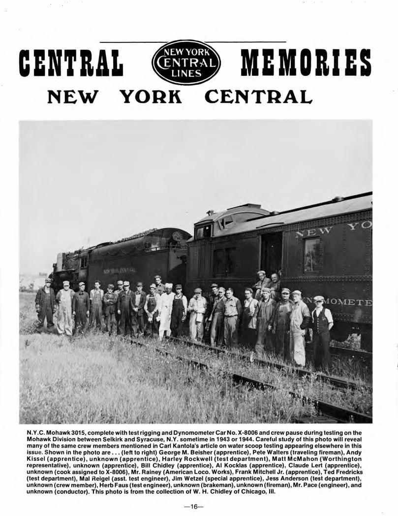
N.Y .C. Mohawk 3015, complete with test rigging and Dynamometer Car No. X-8006 and crew pause during testing on the Mohawk Division between Selkirk and Syracuse, N.Y. sometime in 1943 or 1944. Careful study of this photo will reveal many of the same crew members mentioned in Carl Kantola's article on water scoop testing appearing elsewhere in this issue. Shown in the photo are ... (left to right) George M. Beisher (apprentice), Pete Walters (traveling fireman), Andy Kissel (apprentice), unknown (apprentice), Harley Rockwell (test department), Matt McMahon (Worthington representative), unknown (apprentice), Bill Chidley (apprentice), AI Kocklas (apprentice), Claude Lert (apprentice) , unknown (cook assigned to X-8006), Mr. Rainey (American Loco. Works), Frank Mitchell Jr. (apprentice), Ted Fredricks (test department), Mal Reigel (asst. test engineer), Jim Wetzel (special apprentice), Jess Anderson (test department), unknown (crew member), Herb Faus (test engineer), unknown (brakeman), unknown (fireman), Mr. Pace (engineer), and unknown (conductor). This photo is from the collection of W. H. Chidley of Chicago, Ill.
-16-

SOME NOTES ON THE HISTORY OF WATER SCOOPS AND TRACK PANS
by Edward L. May
Some early railroad tomes ascribe the introduction in the U.S. of this method of replenishing dwindling tender water to the Pennsylvania Railroad, though we have it from contemporary reports in the Railroad Gazette that it was first introduced here by William Buchanan on the Hudson River road in I 870. Regardless , it had been used as early as I 857 on the London & North Western Railway of England and later on the Great Northern of England . In the United States, besides the New York Central and Pennsy, other roads to use track pans at certain high-speed , non-stop main line locations were the Jersey Central , Reading, and B&O between Jersey City and Washington (The Royal Blue Line), the New Haven on its Shore Line Route, and the Milwaukee Road between Chicago and Milwaukee. However, foot for foot of track pan length, no road could compare with the eastern trunk line giants, New York Central and Pennsylvania.
One of the reasons Buchanan first installed pans on the Hudson Div., if we are to believe Railroad Gazette, was to save precious running time in competing with the Pennsy's shorter route New York to Chicago. It does seem to stretch the imagination to suggest that these two roads were already competing speedwise for the New York / Chicago passenger dollar as early as I 870, or even that the water level route was not
at an advantage over the Pennsy's over the Alleghenies despite the longer route miles.
The early track pans were of both wooden and sheet iron construction and approximately 600 feet in length . Thirty miles per hour was deemed the best running speed for jerking' water, and the scoops of those days were manually operated by the fireman. Troughs were inclined at the ends to reduce damage should the fireman neglect to raise the scoop in time, and despite various other experiments to reduce broken scoops this proved best. To reduce dust the track between the rails where the troughs were located was sodded and a steam pipe was run lengthwise along the bottom of the trough to prevent winter freezing. In later years cobblestone pavement was put under the ballast as well as on the surface of the roadway, in the ditches, and over the shoulders of the bank so that the whole structure was protected from the wash caused by the tender scoop. In the beginning it was thought that this watering method might even be adaptable to supply cattle while being transported .
Other advantages than just obviating the stopping for water were presented by the pans. Savings in tender weight or allowing for greater coal capacity also aided longer running and allowed the engineman and fireman time for oiling or exam in-
N.Y .C. J-3a 5440 at the Tivoli, N.Y. track pans on August 30, 1941 pulling the first section of train No. 58, "The Niagara." Edward L. May Collection
-17-
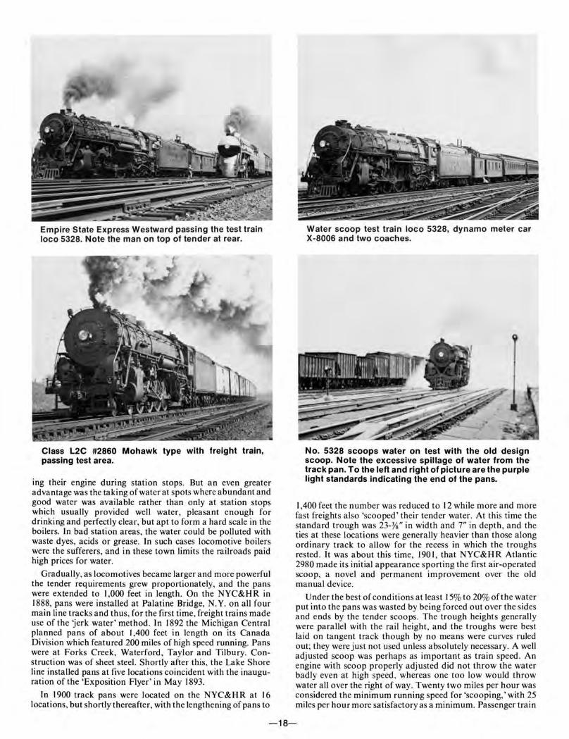
Empire State Express Westward passing the test train loco 5328. Note the man on top of tender at rear.
Class L2C #2860 Mohawk type with freight train, passing test area.
ing their engine during station stops. But an even greater advantage was the taking of water at spots where abundant and good water was available rather than only at station stops which usually provided well water, pleasant enough for drinking and perfectly clear, but apt to form a hard scale in the boilers. In bad station areas, the water could be polluted with waste dyes, acids or grease. In such cases locomotive boilers were the sufferers, and in these town limits the railroads paid high prices for water.
Gradually, as locomotives became larger and more powerful the tender requirements grew proportionately, and the pans were extended to I ,000 feet in length. On the NYC&H R in 1888, pans were installed at Palatine Bridge, N.Y. on all four main line tracks and thus, for the first time, freight trains made use of the 'jerk water' method . In 1892 the Michigan Central planned pans of about I ,400 feet in length on its Canada Division which featured 200 miles of high speed running. Pans were at Forks Creek, Waterford, Taylor and Tilbury. Construction was of sheet steel. Shortly after this, the Lake Shore line installed pans at five locations coincident with the inauguration of the 'Exposition Flyer' in May 1893.
In 1900 track pans were located on the NYC&H R at 16 locations, but shortly thereafter, with the lengthening of pans to
Water scoop test train loco 5328, dynamo meter car X-8006 and two coaches.
No. 5328 scoops water on test with the old design scoop. Note the excessive spillage of water from the track pan. To the left and right of picture are the purple light standards indicating the end of the pans.
I 400 feet the number was reduced to 12 while more and more f~st freights also 'scooped' their tender water. At this time the standard trough was 23-Ys" in width and 7" in depth , and the ties at these locations were generally heavier than those along ordinary track to allow for the recess in which the troughs rested. It was about this time, 1901, that NYC&HR Atlantic 2980 made its initial appearance sporting the first air-operated scoop, a novel and permanent improvement over the old manual device.
Under the best of conditions at least 15% to 20% of the water put into the pans was wasted by being forced out over the sides and ends by the tender scoops. The trough heights generally were parallel with the rail height , and the troughs were best laid on tangent track though by no means were curves ruled out; they were just not used unless absolutely necessary. A well adjusted scoop was perhaps as important as train speed. An engine with scoop properly adjusted did not throw the water badly even at high speed, whereas one too low would throw water all over the right of way . Twenty two miles per hour was considered the minimum running speed for 'scooping,' with 25 miles per hour more satisfactory as a minimum. Passenger train
-18-
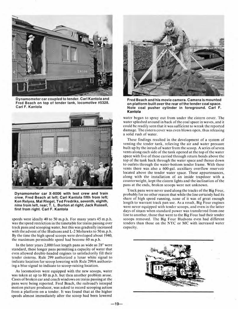
Dynamometer car coupled to tender. Carl Kantola and Fred Beach on top of tender tank, locomotive #5328. Carl F. Kantola
Dynamometer car X-8006 with test crew and train crew. Fred Beach at left; Carl Kantola fifth from left; Ken Relyea, Mal Riegel, Ted Fredriks, seventh, eighth, nine from left, rear; T. L. Burton at right; Jack Russell, first from right. Carl F. Kantola
speeds were ideally 40 to 50 m.p.h. For many years 45 m.p.h. was the speed restriction in the timetable for trains passing over track pans and scooping water, but this was gradually increased with the advent of the Hudsons and L-2 Mohawks to 50 m.p.h. By the time the high speed scoops were developed about 1940, the maximum permissible speed had become 60 m.p.h.
In the later years 2,000foot length pans as wide as 28" were standard , these longer pans permitting a capacity of water that even allowed double-headed engines to satisfactorily fill their tender cisterns. Rule 299 authorized a lunar white signal to indicate location for scoop lowering with Rule 299A authorizing a blue signal to indicate to scoop-raising location.
As locomotives were equipped with the new scoops, water was taken at up to 80 m.p.h. but then another problem arose. Cases of broken car and coach windows on trains passing at the pans were being reported . Fred Beach, the railroad's intrepid motion picture producer, was asked to record scooping action from a platform on a tender. It was found that at the higher speeds almost immediately after the scoop had been lowered
-19-
Fred Beach and his movie camera. Camera is mounted on platform built over the rear of the tender coal space. Note coal pusher cylinder in foreground. Carl F. Kantola
water began to spray out from under the cistern cover. The water splashed around in back of the coal space in waves, and it could be readily seen that it was sufficient to wreak the reported damage. The cistern cover was even blown open, thus releasing a solid rush of water.
These findings resulted in the development of a system of venting the tender tank, relieving the air and water pressure built up by the inrush of water from the scoop. A series of seven vents along each side of the tank opened at the top of the water space with five of these carried through return bends above the top of the tank back through the water space and thence down to outlets through the water-bottom tender frame . With these vents there was also a 600-gal. auxiliary overflow reservoir located above the tender water space. These appurtenances, along with the installation of an inside trapdoor with a counterweight, kept the cistern lights and the inclination of the pans at the ends, broken scoops were not unknown.
Track pans were never used along the tracks of the Big Four, probably for no other reason that while the line certainly had its share of high speed running, none of it was of great enough length to warrant track pan use. As a result , Big Four engines were never equipped with tender scoops, and even in the latter days of ste;:tm when standard power was transferred from one line to another, those that went to the Big Four had their tender scoops removed. The Big Four Hudsons even had different tenders than those on the NYC or MC with increased water capacity.
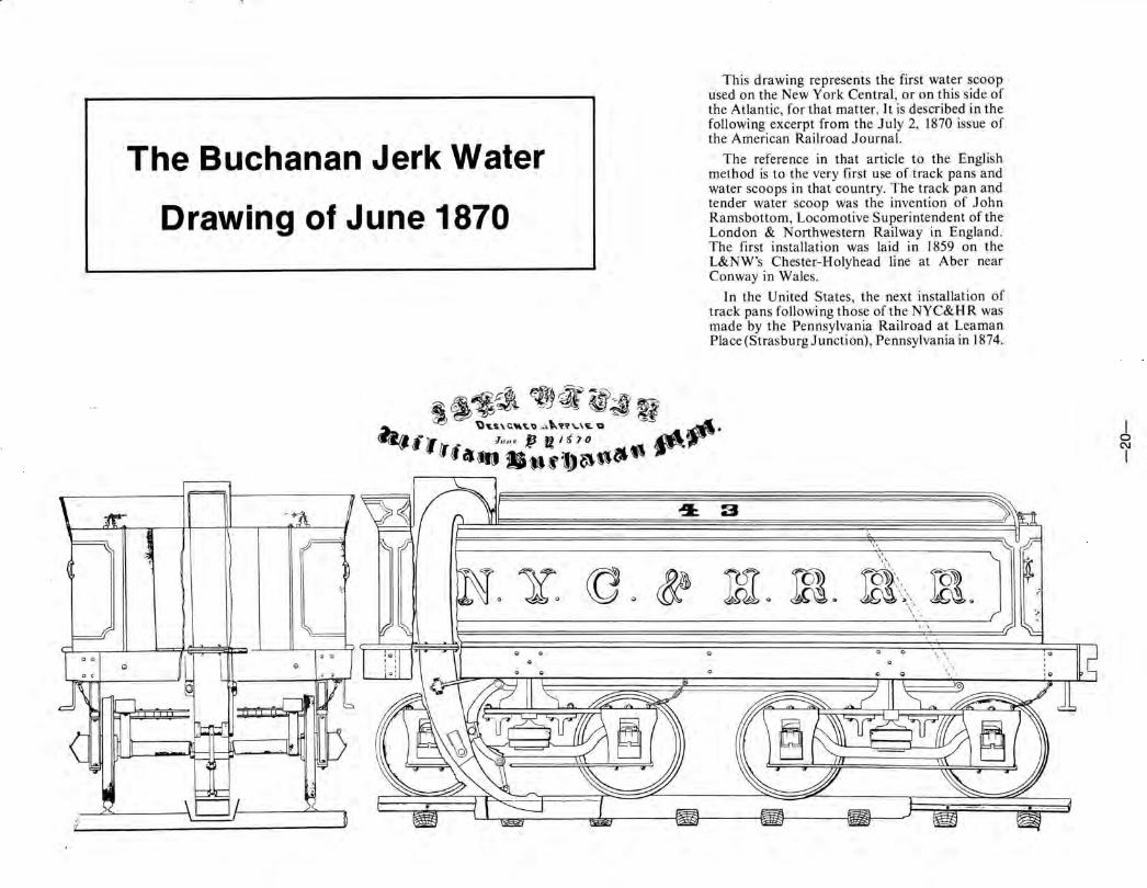
The Buchanan Jerk Water
Drawing of June 1870
This drawing represents the first water scoop used on the New York Central, or on this side of the Atlantic, for that matter. It is described in the following excerpt from the July 2, 1870 issue of the American Railroad Journal.
The reference in that article to the English method is to the very first use of track pans and water scoops in that country. The track pan and tender water scoop was the invention of John Rams bottom, Locomotive Superintendent of the London & Northwestern Railway in England . The first installation was laid in 1859 on the L&NW's Chester-Holyhead line at Aber near Conway in Wales.
In the United States, the next installation of track pans following those of the NYC&H R was made by the Pennsylvania Railroad at Leaman Place (Strasburg Junction), Pennsylvania in 1874.
'. \
0 '.'
I 0 C\1
I
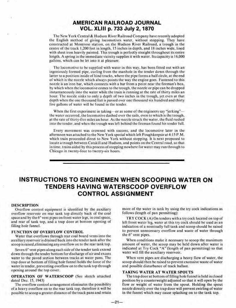
AMERICAN RAILROAD JOURNAL VOL. XLIII p. 733 July 2, 1870
The New York Central & Hudson River Railroad Company have recently adopted the English method of giving locomotives water, without stopping. They have constructed at Montrose station, on the Hudson River Railroad, a trough in the centre of the track I ,200 feet in length, 15 inches in depth, and 18 inches wide, lined with sheet iron heavily painted . This trough is perfectly straight throughout its entire length. A spring in the immediate vicinity supplies it with water. Its capacity is 16,000 gallons, which can be let into it at pleasure.
The locomotive to be supplied with water in this way, has been fitted out with an ingeniously formed pipe, curling from the manhole in the tender down through the latter to a position inside of hind trucks, where the pipe forms a half circle, at the end of which is the nozzle which always points the way the engine goes. Fastened to this nozzle is an iron bar, which connects with a bar from a point near the fireman's box, by which when the locomotive comes to the trough, the nozzle or pipe can be dropped instantaneously into the water while the train is running at the rate of thirty miles an hour. The nozzle sinks to only a depth of two inches in the trough, yet even at that depth when the one thousand feet is passed over one thousand six hundred and thirty five gallons of water will be found in the tender.
When the first experiment in taking- or as some of the engineers say "jerking"the water occurred, the locomotive dashed over the rails, even to which is the trough, at the rate of thirty-five miles an hour. As the nozzle struck the water, the fluid rushed into the tender, and when the trough was left behind the fireman found his tender full.
Every movement was crowned with success, and the locomotive later in the afternoon was attached to the New York special which left Poughkeepsie at 4: 15 P.M. which train proceeded direct to New York without stopping. It is next proposed to locate a trough between Catskill and Hudson, and points on the Central road, so that in time, trains aided by this process of stopping nowhere for water may run through to Chicago in twenty-four to twenty-six hours.
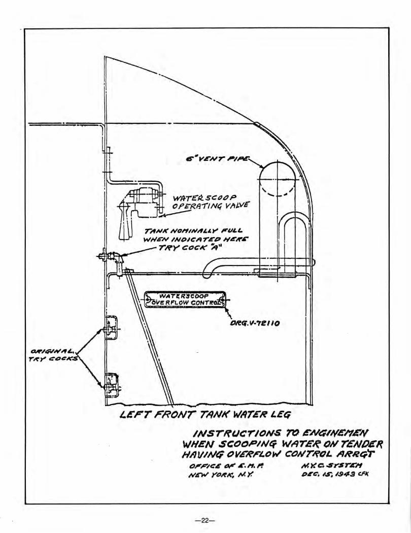
INSTRUCTIONS TO ENGINEMEN WHEN SCOOPING WATER ON TENDERS HAVING WATERSCOOP OVERFLOW
CONTROL ASSIGNMENT
DESCRIPTION Overflow control equipment is identified by the auxiliary
overflow reservoir on rear tank top directly back of the coal space and by the 6" vent pipes on front water legs , in coal space, and rear of tank top, and a trap door at bottom opening of filling hole funnel.
FUNCTION OF OVERFLOW CONTROL Water that overflows through rear coal board vents into the
auxiliary reservoir is drained back into the tender tank after the scoop is raised ,eliminating any overflow on to the rear tank top.
Seven 6" vent pipes along each side of the tender tank extend down through the tender bottom for discharge of air and excess water to the paved section between tracks at water pans. The trap door at bottom of filling hole funnel holds the force of the water in tender, preventing overflow on to the tank top through opening around the top cover.
OPERATION OF WATERSCOOP (See sketch attached dated Dec. 15, 1943)
The overflow control arrangement eliminates the possibility of a heavy overflow on to the rear tank top, therefore it will be possible to scoop a greater distance of the track pans and retain
more of t~e water in tank by using the try cock indications as follows (length of pan permitting):
TRY COCK (A) On tenders with a try cock located on top of left front water leg, water at this try cock should be used as an indication of a nominally full tank and scoop should be raised to prevent unnecessary overflow and waste of water through the 6" vent pipes.
When conditions make it necessary to scoop the maximum amount of water, the scoop may be held down after water is indicated at Try Cock "A" (length of pan permitting) so that water will fill the auxiliary reservoir.
When vent pipes are discharging a heavy flow of water, the scoop should then be raised to prevent excessive waste of water and possible disturbance of track ballast.
TAKING WATER AT WATER SPOUTS The trap door at bottom of filling hole funnel is held in closed
position by a counterweight adjusted so that it will open by the flow or weight of water from the spout. Holding the spout nozzle directly over the trap door will prevent swirling of water in the funnel which may cause splashing on to the tank top.
-21-
-~-
' . • W'lfTE"R.SCtldP A£. OF'E:RII-r"/Nt; VJttVE
· ·~ lffL. ~ I\ \ \ rANK NoHINAI.J.t" PuLL.
4JJ WHEN ~NDit:A-rED H4'H'6" THYCOCK ~·•
0/e(f.ll·?l! II()
1.£FT ri?ONr T'ANK WATER LEt:;
INSTRIJCriONS. 1rJ EN4,}(4'/1EIV WHEN .SCfJOPII.Jfl kiATE~ 0# Y£NO£R HAVINt; OVG'~ri.DW COI/7/ffiL ARRt;.'T
0,-j/#'/t:l evt" .C. H. I'! ,vrw ye~~~ MY.
-22-
H.)( C. .SYSrE/"1 DI'C. I~ 1.943 CFJ(

,
~~~--------------4-/~'-'----------~~ t-< 1511 WJorH opSt::t:JoP -J ~~
~ TOP OF /f'A-IL~ ~ !·•
- - - - ~r--- ~ -~"i__- -I---
~ -~~ - f- - - ~ - - .... , - -- r---- - -.. ~ ~C\1
- 1--- . - ~~ -t- - -- -- r-- - --- -- ~ ____,..--K- ~---- -- -; - - ----It----
-1' -------~a,- -- ----
""--""'- I " " '1' S£ALE" ~sf t:Fil
CR05S SEC/ION t:J~ TRRCK PIJN SIIOW/Nt; WlfTET? SCOOP OV/L!NE IN 1111-XINV/'1 SCtJtJPINt; POSITION
-23-
~ PAN Q Nil.
~ I
~ :s 2 ~
3
~ ~ C) • .. " 5
" u Ill 7 :;) IJ ~ 8 q: ).
Ill 9
tO
II) II
... ~ /2
13
,.,. 0 IS a LJ ...1 ,. 0 ~
17
~ Q: IB .... ,... ., l..j 19 ~
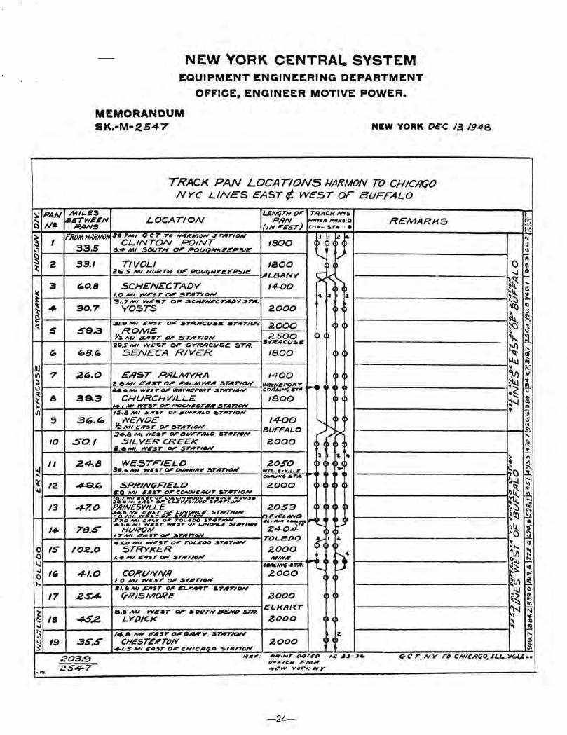
NEW YORK CENTRAL SYSTEM EQUIPMENT ENGINEERING DEPARTMENT
OFFICE, ENGINEER MOTIVE POWER.
MEMORANDUM SK.·M·%547 NEW YORK DEC. 13. 1948
TRACK PAN LOCATIONS HAI?MON TO CHIC/It';() NYC LINES EAST¢ WEST OF BUFFALO
MI~ES L£Nf;l"NOF TRACKN•s BETWEEN LOCATION PRN 1111/ITIIf PlfN .. O ReMARKS
P./INS !{IN FEET) co~• ~rill · •
FROMHMMOII , • . ,,..., 9 t: 7' 7'11 N-'VHIII'ION J .,.197'10/V t I~ 33.5 CLINTON P01NT 1800
~ ... Ml S~'T'H 01'" POI./G+IIrFEPSIE
33.1 TIVOLI I BOO p 2~ . S /WI NQ~trH 01'" POVt;Hit'~EPS/e ,.LBAN'r' ~ <
"O.B SCHENECTADY 14-00· (~ (~ 1.0 /WI W£ST eN" STRTION 4 3 I .1. '!JI. 7MI. W<if'5T 0~ .5CHENECTAII'i'.STIII.
30.7 YOST.S 2.000 <P <
..51.8MI ~,.~.,. o' ~y"";vcu~.- .sr;rrtav 2.000 ( 59.3 ROME. ) ( Y&MI E-"'T 01' STA'T'IQN' 2500
ae.s ,.., ..,.£sr 0' .s.,..RJ<9c"'s.e STA'. 5YRACIJSI!
"8.~ S£NECA RIVeR 1800 )
-2~.0 ERST· P"LMYRA 1400 )
2 .8/WI FAST o;r PNLIIAYH;r STATION ~;cy;,~ ~ • 4 , -~ ~&4M• w1•r- ..,,.,_ANJr .sr-.TION
39.3 CHURCHVILLE I BOO cp H .l Ml W~!JT Q, R'OCHISTitr ~T;f77~ IS.3 Ml 1/i';fSr D,.I~A~o ar,.r1oN'
3(0. '- WE' NO£ 14-00 'r--. p )
IS!""'' ~·As r o,r :)7'"'lrtDN BUFF'AL.O ~ -3+.8 ..... , wear o,r~v,-,.~o STAT;~ ;""'
SO. / .SILVER CREEK 2000 ~ ( p cp 11.6-. IIVI~T o,- ST;fTION
J I a " 2.4-.8 WESTFIELD 2050 p ) ~ ....
3•.6MI W6'5r' 01' 04/N~I;flf' :)T,TIOIIf Wn1.1Yt'ILL6 CCMC..M'O ..5 ;4, •
~cO .SPHINfiFIELO i!OOO c c ) ,0 Ml ~lf!JT Oo" ~ONNI"'UT Sr;rTION ~7 ,., •tt•r ~ COI&.~,,.,~o• '""'•Mt!~..::/'., ...
47.0 PAiNE:s'Yil.L£ c..s.,, ... ~N/1 sr .. r, 2053 cp ) ( ~ ) ~··,...";"' ,#;~; B ~.z:~f ~rHTION ILVEL.NVD -:..~~ ~', ~.::r ,..o:.r.o.; :~ ~~~~~, .. r,.., I£ ... Jif14 ~ ........ ~l. c ~ ·~
78.S HVRON z.t~-o.t'• ) c r 1.7_, ~r,.•r 01" :sr;rrtON TOL.~DO ct; I a.
~s.o _, tNISr o,. r~- :sr;rr,_ ) ( p
102.0 STRYKER 2.000 /. 4 Ml EAS r - ~TAT/ON' Mlllf;r l tf ~-""" .,...,, ~
41.0 CORVIVN,II zooo / . 0 /WI WI~T O'~rATitlllf ~ (~
.I •• MI .EAST Q' ei-A'-T ST,TION
2.5'.4- (ji?ISMORt: 2000 cp cp
8.6/W/ we:sr ~ sovrN 6£111'# SnP. ELKAR.r
4$.2. LYDICK zooo ~ cp /4-.8 hH ~,~.,. ~G-'11' .ST#T/OIV I £.
3S'.S CIIESTEtf'TO/V 2000 > (~ +1.5 IWl EAI:JT' OF" CHICRt;O S.Tifn~
t {~ '" 'II J 1.1
~ 0 ai ~ \11
~~ -~
cS ~~ 10 ::..
~ I)
~ 1:!
~ ~. ... ~ d ~~-. ~ ·~ .... "~t <:li ~
~
!l'l \1
~l ~
~ il ~ ..... loi ,.-.J
" ~, o· "' !1 ~I ~ I
~ ~ Vi
~C> ~ ~~ ;:; I
C)~ ~ ~ ~::5 ... ~ttl ~
" 'llj_ R. 0
* ~~--~ 14V)
~ ~ ... ~- "' ~U') ~ ~ 0
\ ~ ..... .!!?, ~-.I "' ~ ~
~ to. ai Oi
203.9 'f., .. P~INT Qil9r6'p ;.;! ,.,~ . .Jr. t; C' T. Ill.,.. Tt' CNICRr;O, ~LL.. . ~(;.J,.l. •• P,.,.,.:.r c""'R
...... ZS4-7 ""'~!'"' VfiPKNY
-24-
~ .. ~
~ ... 1,
~
~ ~
~
I~ 1--
~ \!>
~ ~
-... n
~
PAN N2
I
2.
3
4
5
6
7
8 -9
10
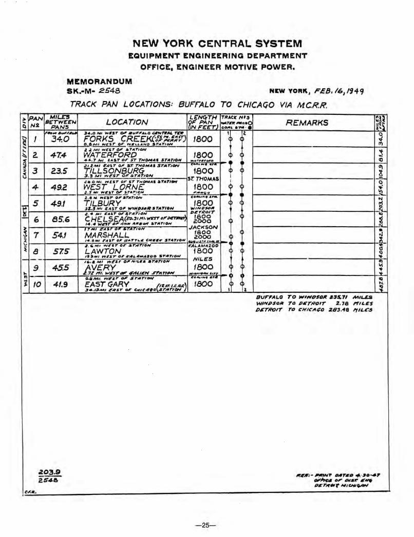
NEW VOAK CENTRAL SYSTEM EQUIPMENT ENGINEERING DEPARTMENT
OFFICE, ENGINEER MOTIVE POWER.
MEMORANDUM SK.•M• 2S48 NEW YORKJ FEB~/61 1949
TRACK PAN LOCATIONS: BUFrALO TO CHICAGO VIA MCR.R. MILES
LOCATION L~Nq.TH TRACIC HI:S
BcTWc£N ~f PAN """'"'-"•Q REMARKS PANS 'N F'£~T)
G-£ ·-· · · 1"_ ... _,.#611 .Jo£,0 /WI IN&'ST 0' ~~~''A•O ~f'II/W. rtrJr I a 34.0 FORKS CRE£KC1P~:~:;r) I BOO <P
8 ~MI WEST o,r W&'UANO STATION
Z .l Ml WICST 0' .T.IITION
47.4 WATERFORD 1800 (~ +4-. 7 Nl EAST 0/f' ST TN~AI STATION fl/llf""r""'OIIfo ; iUZMI EI!IST 0' ST. TNOMAJ STATION •- ... ,. •r"'
23.5 I'LML;~9!1§P~f11(~N ·- 1800 5T. THOMAS
.!16 .0 IWI . .VE5T OF 5T THOMAS ATA'TION I
49.2 WEST LORN£ reoo (~ Z .S 411 W&'ST 0' .ITA!:I~N-- ,.,.~"" ••• l . 8 M ..,EST O/f'aTATION Co.e41""'• ......
4-9.1 TILBURY fBOO <P (
31-J Ml £"5T 01' llll'fiiPU/IISTA'TION WINOS<>A
z.• ~~ liAiT -STAriDN D~TROIT
BS.b CHELSEA(SD·''"'· I/(5TT'o,..~ 1800 14 . .. W6frO'.!INIIIA,..- IOTATION eooo (
I 7MI /~!'AS. 01/0 :tijrAriON JACKSON
54.1 MARSHALL taoo 2000
14 . tJ.WI I'AST 01' UAorT .. II ~R-Ill' ~TilT/ON [.....,.,,~,,.. ......... ~ Z·"""' WE5rolf'SrNrloN KAl-AMAZOO
57.5 LAWTON 1800 <P If~ ... / lllll~r 0, lr41.JIMA1100 a rATION
NIL.ES '"· • Mt wEsr o,.,.,,,,. •r,rtoN
45.5 AY!.~Xrlllf'"~"t'Di '"''"_,
f800 (~ Atll6/lll,...,. .,,.r
~~ 0./AMI. WEST- STIIIriOI+/ ~·~~~., .. ., .. 41.9 EAST GARY l~cn:t.e.R-R) 1800 (~
~4.1~-~ .EAST - ~""lt'J/IfiO SrJ/IrlfJN z. BVF",AI..O TO WIHDSQ/t ·3~11 MIL£& WINPS0/11 TO P~TRtUT Z. 78 l"fiL£S D&THOIT TO CHIOII;O :Z83,<f8 'fiL£".$
c·~ ~!~
0 -I IT)
~ co
i 0 .,.: 'tL N ~ -~ i-~ d Q ... Ill It{
: IQ N.
~
~03.9 lrlfK;- ~.,. ~N~r•• .,._ .,o-41' 2.54& ,.~ .,,. .,.5.,. ... ..,.
•~"r~.,r 14#/CNtfiAN
CF.Ir.,
-25-
Speed Of Train M.P.H.
65 75
65 75 80
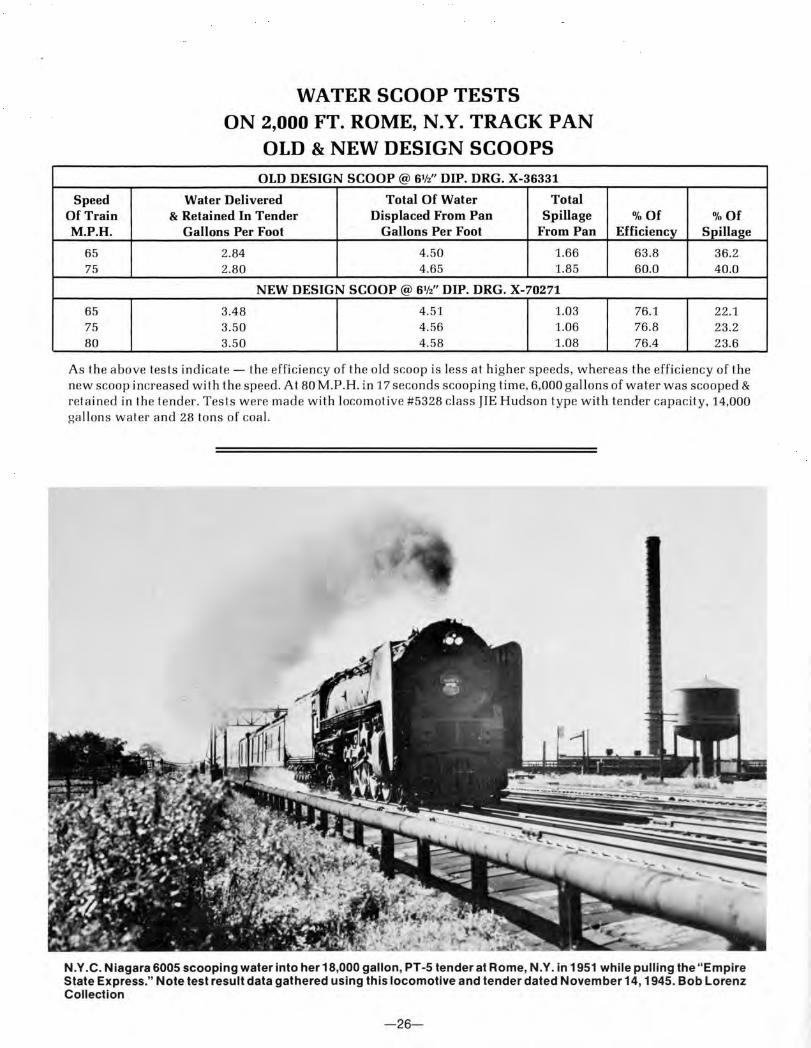
WATER SCOOP TESTS ON 2,000 FT. ROME, N.Y. TRACK PAN
OLD & NEW DESIGN SCOOPS
OLD DESIGN SCOOP @ 6W' DIP. DRG. X-36331
Water Delivered Total Of Water Total & Retained In Tender Displaced From Pan Spillage
Gallons Per Foot Gallons Per Foot From Pan
2.84 4.50 1.66 2.80 4.65 1.85
NEW DESIGN SCOOP@ 6W' DIP. DRG. X-70271
3.48 4.51 1.03 3.50 4.56 1.06 3.50 4.58 1.08
%Of % Of Efficiency Spillage
63 .8 36.2 60.0 40.0
76.1 22.1 76.8 23.2 76.4 23.6
As the a bove tests indica te- th e efficiency of the old scoop is less at higher speeds, whereas the efficiency of the new scoop increased w ith the speed. At 80 M.P.H . in 17 seconds scooping time, 6,000 gallons of water w as scooped & retained in the tender. T es ts w ere made with locomotive #5328 class JIE Hudson type with tender capacity, 14,000 ga ll ons water and 28 tons of coa l.
N.Y .C. Niagara 6005 scooping water into her 18,000 gallon, PT -5 tender at Rome, N.Y. in 1951 while pulling the "Empire State Express." Note test result data gathered using this locomotive and tender dated November 14, 1945. Bob Lorenz Collection
-26-
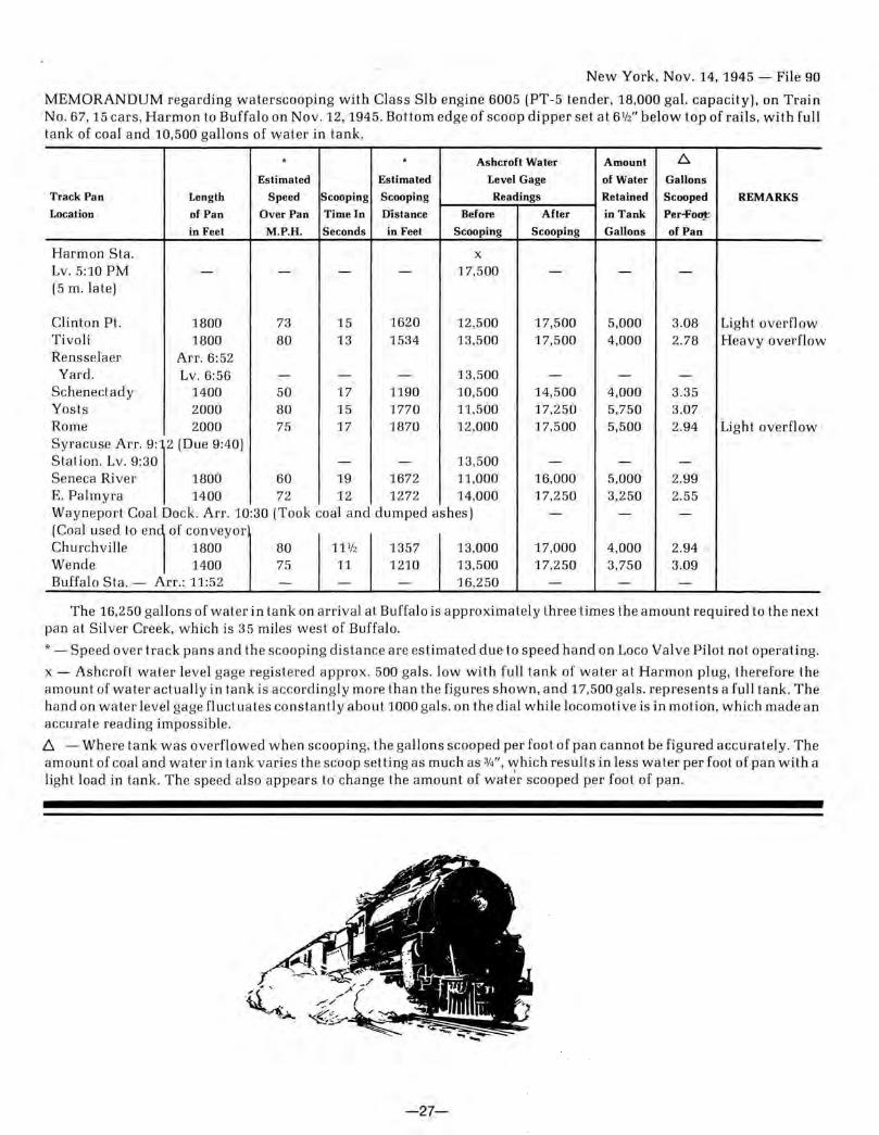
New York, Nov. 14, 1945- File 90
MEMORANDUM regarding waterscooping with Class Sib engine 6005 (PT-5 tender, 18,000 ga l. capacity), on Train No. 67, 15 cars, Harmon to Buffa lo on Nov. 12, 1945. Bottom edge of scoop dipper set at 61fz" below top of rails, wit h fu ll tank of coal and 10,500 gallons of water in tank .
. . Ashcroft Wa ter Amount L::,.
Estimated Estimated Level Gage of Water Gallons
Track Pan Length Speed Scooping Scooping Readings Retained Scooped REMARKS
Location of Pa n Over Pan Time In Distance Before After in Ta nk Per-+'o!J!.."
in Feet M.P.H. Seconds in Feet Scooping Scooping Gallons of Pan
Harmon Sta. X
Lv. 5:10PM - - - - 17,500 - - -(5 m. late]
Clinton Pt. 1800 73 15 1620 12,500 17,500 5,000 3.08 Ligh t overflow Tivoli 1800 80 13 1534 13,500 17,500 4,000 2.78 Heavy overflo w Rensse laer Arr. 6:52 Yard . Lv. 6:56 - - - 13,500 - - -
Schenectady 1400 50 17 1190 10,500 14,500 4,000 3.35 Yosts 2000 80 15 1770 11,500 17,250 5,750 3.07 Rome 2000 75 17 1870 12,000 17,500 5,500 2.94 Light overflow Sycacu" An. g,r (Due 9'40) Station. Lv. 9:30 - - 13,500 - - -Seneca River 1800 60 19 1672 11,000 16,000 5,000 2.99 E. Palmyra 1400 72 12 1272 14,000 17,250 3,250 2.55 Wayneport Coal Dock. Arr. 10:30 (Took coal and dumped ashes) - - -(Coal ""d to en~ of conveyoc Churchville 1800 80 111fz 1357 13,000 17,000 4,000 2.94 Wende 1400 75 11 1210 13,500 17,250 3,750 3.09 Buffalo Sta.- Arr.: 11:52 - - - 16,250 - - -
The 16,250 gallons of water in tank on arriva l at Buffalo is approximately three times the amount required to the next pan at Silver Creek, which is 35 miles west of Buffalo.
* - Speed over track pans a nd the scooping distance are estimated due to speed hand on Loco Va lve Pilot not operating.
x- Ashcroft water leve l gage registered approx. 500 gals. low with full tank of water at Harmon plug, therefore the amount of water actually in tank is accordingly more than the figures shown, and 17,500 gals. represe nts a full tank. The hand on water level gage fluctuates constant ly about 1000 gals. on the dia l while locomotive is in motion, which made an accurate reading impossible.
~ - Where tank was overflowed when scooping, the ga ll ons scooped per foot of pan cannot be figured accurately. The amount of coal and water in tank varies the scoop setting as much as 3/4'', which results in less water per foot of pan w ith a light load in tank . The speed also appears to change the amount of wat~r scooped per foot of pan.
-27-