cavity filters & duplexers - hutton communications the industry leading brands of both bird...
TRANSCRIPT

Cavity Filters & DuplexersYou’re heard, loud and clear.
Bird® Technologies Group (BTG) is a global, innovative supplier
of RF products, systems, services and educational solutions.
Combining the industry leading brands of both Bird Electronic
and TX RX Systems in one company reinforces the BTG
commitment to providing RF Measurement and Management in
Your World.
Our portfolio includes hardware, software, components and services. We
offer these innovative products and services through our industry lead-
ing product line brands, Bird Electronic Corp and TX RX Systems. We
provide test instruments that are highly accurate, rugged and easy to
use. Industry leading components and products such as site analyzers,
wattmeters, digital sensors, samplers, antennas, signal boosters,
and tower mounted amplifiers. Furthermore, we offer dependable
engineering, calibration and educational services for land mobile radio,
cellular, semiconductor, broadcast, medical, military and government
applications.
All BTG products can be serviced and calibrated by the Bird Service
Center (BSC). BSC provides a full range of service and support. With over
130 years of combined product and calibration experience, our service
technicians and product experts offer reliable service and customer care.
Bird Service Centers and Service Partners are located World Wide
providing a full range of service and support for your Bird Products.
Catalogs offered by Bird Technologies Group(To view or download go to www.bird-technologies.com)
Bird General Catalog
RF & Microwave Components Catalog
Transmit Combiners Catalog
Cavity Filters & Duplexers Catalog
Antennas Catalog
Tower Top Amplifiers, Receiver Multicouplers & Preselectors Catalog
Isolators & Loads Catalog
In-Building Coverage Catalog (Signal Boosters & Accessories)
Bird® Technologies Group combines the industry leading brands of both Bird Electronic and TX RX Systems and is a global, innovative supplier of RF products,systems, services and educational solutions. Bird® Technologies Group reserved the right to modify specifications or discontinue any product without notice.
You’re heard, loud and clear.
30303 Aurora Rd. :: Solon, OH 44139 :: 866.695.4569 :: www.bird-technologies.com
©2009 Bird Technologies GroupCavDup-10142009

tel: 866.695.4569 fax: 716.549.4772 e: [email protected] Technologies group reserVes The righT To ModiFY speciFicATions or disconTinue AnY producT WiThouT noTice TerMs And condiTions posTed on hTTp://WWW.Bird-Technologies.coM/sAles/BTg_Tc.pdF
Cavity Filtersresonant cavity filters are the primary building blocks of duplexers, multicouplers and preselectors. however, their use is not lim-ited to these specific applications. individual or cascaded cavities may be used for a variety of interference fighting chores, such as cleaning up the performance of existing filter systems that have inadequate isolation or off-channel interference rejection. At crowded antenna sites, cavity filters are ideal for quieting noisy transmitters or for preventing transmitter iM mixing. receiver front-end selectivity can be greatly enhanced by the use of additional filtering, thus eliminating many desensitization, iM, and overload problems.
When used in conjunction with a spectrum analyzer or service monitor, cavity filters can allow a detailed analysis of lower-level transmitter noise. This lower-level noise is one of the major sources of interference at multi-transmitter sites. cavity filters can stand alone as pieces of test equipment for analyzing many receiver iM problems and can also help determine the best type of filter to use for a permanent fix.
Four types of cavity filters are designed and manufactured by TX rX systems: Bandpass, T-pass®, Vari-notch® and series-notch®. each uses a specific type of loop assembly which provides the desired frequency response. The Vari-notch® and series-notch® filters use one loop assembly per cavity and incorporates a tuning capacitor. The Bandpass and Tpass® designs utilize 2 loop assemblies per cavity.
Cavity FiltersIntroduction & Construction
1
silver plated connectors with gold pins reduce the risk of intermod; especially at higher frequencies
silver plated probes insure conductivity even if corrosion occurs
nickel plated invar has high temperature coefficient and resists rust
push/pull tuning (not threaded) mechanism stays on frequency when locked down.
Temperature compensation stem keeps cavity on frequency
slotted probe fingers insure excellent contact between stationary and moveable probes
heliarc welded end cap = one piece construction which maximizes ‘Q’
Field adjustable loops allow changes in selectivity as well as circuit style
Fine tuning rod provides an easy way to optimize tuning

tel: 866.695.4569 fax: 716.549.4772 e: [email protected] Technologies group reserVes The righT To ModiFY speciFicATions or disconTinue AnY producT
WiThouT noTice TerMs And condiTions posTed on hTTp://WWW.Bird-Technologies.coM/sAles/BTg_Tc.pdF
Cavity FiltersTheory of Operation and Applications
BaNDPassThe Bandpass cavity passes one narrow band of frequencies and attenuates all others with increasing attenuation above and below the pass frequency. it is equivalent to a parallel-tuned circuit and is most often used for general transmitter spurious clean-up or a sharpening of a single receiver front end selectivity with or without amplification. TX rX bandpass cavities (4”, 6”, 8” and 10”) have adjustable selectivity characteristics (rotatable loops) to allow a trade-off between insertion loss (0.5--3.0 dB) and selectivity. Maximum power handling is typically determined by insertion loss setting.
t-Pass®
T-pass® is a variation of the Bandpass cavity used for our expandable multicoupler applications. its general characteristics are nearly identical to a bandpass cavity but the output loop has a pair of n-connectors so it can easily be coupled to other channels.
series NOtCH®
The series-notch® passes a relatively wide band of frequencies while rejecting a very narrow band of frequencies. it is equivalent to a series-tuned circuit. notch depth is variable from 15 - 25 dB. pass and notch frequencies must be known so that the optimum loop assembly can be used. This is the best filter for very close separations (200 Khz to 400 Khz) in uhF applications.
vari-NOtCH®
The Vari-notch® design passes a relatively narrow band of frequencies and rejects (notches out) a relatively wide frequency band. equivalent to a combination series-tuned and parallel-tuned circuit, this filter has a greater notch depth than the series-notch® design. The notch depth is adjustable but varies with passband insertion loss (0.3dB or 0.6dB typical) and the difference between pass and notch frequencies. Vari-notch® is ideal for moderately close to wide separations (400 Khz and greater) in uhF applications.
CasCaDiNG FiltersAll cavity types mentioned above may be cascaded to achieve an arithmetic sum of individual filter attenuation. up to 6 dB of additional attenuation can be achieved when the proper length of cable is used to interconnect the cavities. (This additional 6 dB does not occur in the filter passband but only at frequencies where moderate to high attenuation occurs.) A TX rX system specialist can assist you in ordering the proper length of interconnecting cable for your frequencies.
2
Various low-loss high-rejection Models to choose FromAll loop plate/connector assemblies are silver-or Alballoy®-plated for low iMWelded cavity construction and silver-plated tunable probe and loops give superior pass and reject characteristics

tel: 866.695.4569 fax: 716.549.4772 e: [email protected] Technologies group reserVes The righT To ModiFY speciFicATions or disconTinue AnY producT WiThouT noTice TerMs And condiTions posTed on hTTp://WWW.Bird-Technologies.coM/sAles/BTg_Tc.pdF
Cavity FiltersBandpass108-174 MHz
3
sPeCiFiCatiONs, eleCtriCalModel Number/ Frequency range
11-35-0111-35-0211-35-0511-35-0611-36-0111-36-02
108-136 Mhz108-136 Mhz108-136 Mhz108-136 Mhz132-150 Mhz132-150 Mhz
Max. pwr., percavity, @ 0.5 dB il
270 Watts
Max. pwr., percavity, @ 3.0 dB il
60 Watts
impedance 50 ohms
vsWr 1.25:1 max.
Cavity length (electrical)
1/4l
temperature range -30 to + 60 c°
Cavity size, diameter (inches)
11-35-0111-35-0211-35-0511-35-0611-36-0111-36-02
6.6256.62510106.6256.625
Number of Cavities 11-35-0111-35-0211-35-0511-35-0611-36-0111-36-02
121212
Connectors n
Dimensions, HxWxD (inches)
11-35-0111-35-0211-35-0511-35-0611-36-0111-36-02
31.5x6.625x6.62531.5x6.625x6.62533.5x10x1033.5x10x1026 x6.625x6.62526 x6.625x6.625
shipping Weight 11-35-0111-35-0211-35-0511-35-0611-36-0111-36-02
20 lbs42 lbs27 lbs56 lbs15 lbs30 lbs
sPeCiFiCatiONs, eleCtriCalModel Number/ Frequency range
11-36-0511-36-0611-37-0111-37-0211-37-0511-37-0611-37-09
132-150 Mhz132-150 Mhz144-174 Mhz144-174 Mhz144-174 Mhz144-174 Mhz144-174 Mhz
Max. pwr., per cavity, @ 0.5 dB il 11-37-09
270 Watts 100 Watts
Max. pwr., per cavity, @ 3.0 dB il 11-37-09
60 Wattsn/A
impedance 50 ohms
vsWr 1.25:1 max.
Cavity length (electrical)
1/4l
temperature range -30 to + 60 c°
Cavity size, diameter (inches)
11-36-0511-36-0611-37-0111-37-0211-37-0511-37-0611-37-09
10106.256.2510104
Number of Cavities 11-36-0511-36-0611-37-0111-37-0211-37-0511-37-0611-37-09
1212121
Connectors n
Dimensions, HxWxD (inches)
11-36-0511-36-0611-37-0111-37-0211-37-0511-37-0611-37-09
26 x10 x1026 x10 x1026 x6.625x6.62526 x6.625x6.62526 x10 x1026 x10 x1015 x 4 x 4
shipping Weight 11-36-0511-36-0611-37-0111-37-0211-37-0511-37-0611-37-09
21 lbs44 lbs15 lbs30 lbs21 lbs44 lbs5 lbs
Model 11-35-01
Frequency (MHz)
Atte
nuat
ion
(dB
)
Frequency (MHz)
Atte
nuat
ion
(dB
)
Model 11-36-05
Frequency (MHz)
Atte
nuat
ion
(dB
)
Model 11-36-01
Frequency (MHz)
Atte
nuat
ion
(dB
)
Model 11-37-01

tel: 866.695.4569 fax: 716.549.4772 e: [email protected] Technologies group reserVes The righT To ModiFY speciFicATions or disconTinue AnY producT
WiThouT noTice TerMs And condiTions posTed on hTTp://WWW.Bird-Technologies.coM/sAles/BTg_Tc.pdF
Cavity FiltersBandpass
225-400 / 406-512 MHz
4
sPeCiFiCatiONs, eleCtriCal
Model Number/ Frequency range
11-53-0111-65-2611-70-0111-70-0211-70-0511-70-0611-70-0911-70-1111-70-12
225-400 Mhz406-420 Mhz450-470 Mhz450-470 Mhz450-470 Mhz450-470 Mhz450-470 Mhz450-470 Mhz450-470 Mhz
Max. pwr., per cavity, @ 0.5 dB il
11-53-0111-65-2611-70-0111-70-0211-70-0511-70-0611-70-0911-70-1111-70-12
100 Watts 270 Watts270 Watts270 Watts270 Watts270 Watts100 Watts270 Watts270 Watts
Max. pwr., per cavity, @ 3.0 dB il
11-53-0111-65-2611-70-0111-70-0211-70-0511-70-0611-70-0911-70-1111-70-12
100 Watts60 Watts60 Watts60 Watts60 Watts60 Wattsn/A60 Watts60 Watts
impedance 50 ohms
vsWr 1.25:1 max.
Cavity length (electrical)
11-53-0111-65-2611-70-0111-70-0211-70-0511-70-0611-70-0911-70-1111-70-12
3/4l3/4l1/4l1/4l1/4l1/4l1/4l1/4l3/4l3/4l
temperature range -30 to + 60 c°
Cavity size, diameter (inches)
11-53-0111-65-2611-70-0111-70-0211-70-0511-70-0611-70-0911-70-1111-70-12
8106.256.25101046.256.25
Number of Cavities 11-53-0111-65-2611-70-0111-70-0211-70-0511-70-0611-70-0911-70-1111-70-12
121212112
Connectors11-70-09
nBnc
Dimensions, HxWxD (inches)
11-53-0111-65-2611-70-0111-70-0211-70-0511-70-0611-70-0911-70-1111-70-12
25x8x826 x10x1011.5x6.625x6.62511.5x6.625x6.62512.5x10x1012.5x10x109x4x426x6.625x6.62526x6.625x6.625
shipping Weight 11-53-0111-65-2611-70-0111-70-0211-70-0511-70-0611-70-0911-70-1111-70-12
8.6 lbs43 lbs8 lbs16 lbs11 lbs23 lbs4 lbs12 lbs25 lbs
sPeCiFiCatiONs, eleCtriCal
Model Number/ Frequency range
11-70-2511-70-2611-69-0111-69-0211-69-0511-69-0611-69-0911-69-1111-69-12
450-470 Mhz450-470 Mhz470-512 Mhz470-512 Mhz470-512 Mhz470-512 Mhz470-512 Mhz470-512 Mhz470-512 Mhz
Max. pwr., per cavity, @ 0.5 dB il 11-69-09
270 Watts100 Watts
Max. pwr., per cavity, @ 3.0 dB il 11-69-09
60 Wattsn/A
impedance 50 ohms
vsWr 1.25:1 max.
Cavity length (electrical)
11-70-2511-70-2611-69-0111-69-0211-69-0511-69-0611-69-0911-69-1111-69-12
3/4l3/4l1/4l1/4l1/4l1/4l1/4l1/4l3/4l3/4l
temperature range -30 to + 60 c°
Cavity size, diameter (inches)
11-70-2511-70-2611-69-0111-69-0211-69-0511-69-0611-69-0911-69-1111-69-12
10106.256.25101041010
Number of Cavities 11-70-2511-70-2611-69-0111-69-0211-69-0511-69-0611-69-0911-69-1111-69-12
121212112
Connectors11-69-09
nBnc
Dimensions, HxWxD (inches)
11-70-2511-70-2611-69-0111-69-0211-69-0511-69-0611-69-0911-69-1111-69-12
26x10x1026 x10x1011.5x6.625x6.62511.5x6.625x6.62512.5x10x1012.5x10x109x4x412.5x10x1026x10x10
shipping Weight 11-70-2511-70-2611-69-0111-69-0211-69-0511-69-0611-69-0911-69-1111-69-12
21 lbs43 lbs8 lbs16 lbs11 lbs23 lbs4 lbs21 lbs43 lbs
Frequency (MHz)
Atte
nuat
ion
(dB
)
Model 11-70-26
Frequency (MHz)
Atte
nuat
ion
(dB
)
Model 11-70-25
Frequency (MHz)
Atte
nuat
ion
(dB
)
Model 11-70-12
Frequency (MHz)
Atte
nuat
ion
(dB
)
Model 11-70-11

tel: 866.695.4569 fax: 716.549.4772 e: [email protected] Technologies group reserVes The righT To ModiFY speciFicATions or disconTinue AnY producT WiThouT noTice TerMs And condiTions posTed on hTTp://WWW.Bird-Technologies.coM/sAles/BTg_Tc.pdF
Cavity FiltersBandpass746-960 MHz
5
sPeCiFiCatiONs, eleCtriCal
Model Number/Frequency range
11-83B-1111-83B-1211-86-1111-86-12
746-869 Mhz746-869 Mhz806-821 Mhz806-821 Mhz
Max. pwr., per cavity, @ 0.5 dB il
270 Watts
Max. pwr., per cavity, @ 3.0 dB il
60 Watts
impedance 50 ohms
vsWr 1.25:1 max.
Cavity length (electrical)
3/4l
temperature range -30 to + 60 c°
Cavity size, diameter (inches)
6.625
Number of Cavities 11-83B-1111-83B-1211-86-1111-86-12
1212
Connectors n
Dimensions, HxWxD (inches)
11-83B-1111-83B-1211-86-1111-86-12
14x6.625x6.62514x6.625x6.62513x6.625x6.62513x6.625x6.625
shipping Weight 11-83B-1111-83B-1211-86-1111-86-12
10 lbs19 lbs9 lbs18 lbs
sPeCiFiCatiONs, eleCtriCal
Model Number/ Frequency range
11-87-1111-87-1211-88-1111-88-1211-90-05
851-866 Mhz851-866 Mhz806-960 Mhz806-960 Mhz806-960 Mhz
Max. pwr., per cavity, @ 0.5 dB il
270 Watts
Max. pwr., per cavity, @ 3.0 dB il
60 Watts
impedance 50 ohms
vsWr 1.25:1 max.
Cavity length (electrical)
3/4l
temperature range -30 to + 60 c°
Cavity size, diameter (inches)
6.625
Number of Cavities 11-87-1111-87-1211-88-1111-86-1211-90-05
12121
Connectors n Dimensions, HxWxD (inches)
11-87-1111-87-1211-88-1111-86-1211-90-05
13x6.625x6.62513x6.625x6.62513x6.625x6.62513x6.625x6.6256.5x4x4
shipping Weight 11-87-1111-87-1211-88-1111-86-1211-90-05
9 lbs18 lbs9 lbs18 lbs3 lbs
Frequency (MHz)
Atte
nuat
ion
(dB
)
Model 11-86-11
Frequency (MHz)
Atte
nuat
ion
(dB
)
Model 11-87-11
Frequency (MHz)
Atte
nuat
ion
(dB
)
Model 11-88-11
Frequency (MHz)
Atte
nuat
ion
(dB
)
Model 11-90-05

tel: 866.695.4569 fax: 716.549.4772 e: [email protected] Technologies group reserVes The righT To ModiFY speciFicATions or disconTinue AnY producT
WiThouT noTice TerMs And condiTions posTed on hTTp://WWW.Bird-Technologies.coM/sAles/BTg_Tc.pdF
Cavity FiltersSeries Notch
108-174 MHz
6
Frequency (MHz)
Atte
nuat
ion
(dB
)
Model 20-35-02
Frequency (MHz)
Atte
nuat
ion
(dB
)
Model 20-37-01
Frequency (MHz)
Atte
nuat
ion
(dB
)
Model 20-37-05
Frequency (MHz)
Atte
nuat
ion
(dB
)
Model 20-37-06
Model Number/ Frequency range
20-35-01 20-36-01 20-37-01 20-37-05
108-136 Mhz 132-150 Mhz 144-174 Mhz 144-174 Mhz
insertion loss vs. Frequency separations / with single cavity, notch depth @ 15 dB / with single cavity, notch depth @ 20 dB
20-35-01
20-36-01
20-37-01
20-37-05
100 khz / <1.0 dB /<1.5 dB 250 khz / <0.2 dB / <0.3 dB 500 khz / <0.2 dB / <0.2 dB 1 Mhz / <0.2 dB / <0.2 dB 100 khz / <1.0 dB / <1.5 dB 250 khz / <0.2 dB / <0.3 dB 500 khz / <0.2 dB / <0.2 dB 1 Mhz / <0.2 dB / <0.2 dB 100 khz / <1.0 dB / <1.8 dB 250 khz / <0.2 dB / <0.3 dB 500 khz / <0.2 dB / <0.2 dB 1 Mhz / <0.2 dB / <0.2 dB 50 khz / <0.2 dB / - 100 khz / - / <1.0 dB 250 khz / <0.2 dB / <0.2 dB 500 khz / <0.2 dB / <0.2 dB 1 Mhz / <0.2 dB / <0.2 dB
impedance 50 ohms vsWr 1.5:1 max. Max. pwr. (Watts) @ stated separation
20-37-05
60, 250, 350, 350 80, 150, 350, 350, 350
Cavity length (electrical)
1/4l
temperature range, °C
-30 to + 60
Cavity size, diameter 20-37-05
6.625” 10”
Number of Cavities
1
Cavity Height (inches)
20-35-01
20-36-01 20-37-01 20-37-05
31.5; w / tuning rod extended, 43 max. 26, w / tuning rod extended, 38 max. 26, w / tuning rod extended, 38 max. 26, w / tuning rod extended, 38 max.
Width 20-37-05
6.625” 10”
Depth 20-37-05
6.625” 10”
Connectors n Weight, lbs. 20-35-01
20-36-01 20-37-01 20-37-05
18 17 17 22
Model Number / Frequency range
20-35-02 20-36-02 20-37-02 20-37-06
108-136 Mhz 132-150 Mhz 144-174 Mhz 144-175 Mhz
insertion loss vs. Frequency separations
20-37-06
100 khz, 250 khz, 500 khz, 1 Mhz 50 khz, 100 khz, 250 khz, 500 khz, 1 Mhz
with single cavity, notch depth @ 15 dB 20-37-06
<2.0 dB, <0.6 dB, <0.5 dB, <0.4 dB <3.5 dB, - , <0.5 dB, <0.5 dB, <0.4 dB
with single cavity, notch depth @ 20 dB
20-35-02 20-36-02 20-37-02 20-37-06
<3.0 dB, <0.8 dB, <0.5 dB, <0.4 dB <3.0 dB, <0.8 dB, <0.5 dB, <0.4 dB <3.6 dB, <0.8 dB, <0.5 dB, <0.4 dB -, <2.0 dB, <0.6 dB, <0.5 dB, <0.4 dB
impedance 50 ohms vsWr 1.5:1 max. Max. pwr. (Watts) @ stated separation
20-37-06
60, 250, 350, 350 80, 150, 350, 350, 350
Cavity length (electrical)
1/4l
temperature range, °C
-30 to + 60
Cavity size, diameter
20-37-06
6.625” 10”
Number of Cavities
2
Cavity Height (inches)
20-35-02 20-36-02 20-37-02 20-37-06
31.5; w/ tuning rod extended, 43 max. 26, w/ tuning rod extended, 38 max. 26, w/ tuning rod extended, 38 max. 26, w/ tuning rod extended, 38 max.
Width 20-37-06
6.625” 10”
Depth 20-37-06
6.625” 10”
Connectors n
Weight, lbs. 20-35-02 20-36-02 20-37-02 20-37-06
36 34 34 45

tel: 866.695.4569 fax: 716.549.4772 e: [email protected] Technologies group reserVes The righT To ModiFY speciFicATions or disconTinue AnY producT WiThouT noTice TerMs And condiTions posTed on hTTp://WWW.Bird-Technologies.coM/sAles/BTg_Tc.pdF
Cavity FiltersSeries Notch450-470 MHz
7
Frequency (MHz)
Atte
nuat
ion
(dB
)
Model 20-70-01
Frequency (MHz)
Atte
nuat
ion
(dB
)
Model 20-70-02
Model 20-70-25
Frequency (MHz)
Atte
nuat
ion
(dB
)
Frequency (MHz)
Atte
nuat
ion
(dB
)
Model 20-70-26
sPeCiFiCatiONs, eleCtriCal
Model Number /Frequency range
20-70-0120-70-25
450-470 Mhz450-470 Mhz
Frequency separations vs. insertion loss / With single cavity, notch depth @ 15 dB /With single cavity, notch depth @ 20 dB
20-70-01
20-70-25
175 khz / 1.5 dB / -250 khz / 0.7 dB / 1.5 dB 275 khz / - / 1.2 dB 500 khz / 0.2 dB / 0.4 dB1 Mhz / 0.1 dB / 0.1 dB100 khz / 1.2 dB / -200 khz / - / 0.5 dB250 khz / 0.4 dB / 0.4 dB500 khz / <0.1 dB / 0.1 dB1 Mhz / <0.1 dB / <0.1 dB
impedance 50 ohms
vsWr 1:5:1 max.
Cavity length (electrical)
20-70-0120-70-25
1/4l3/4l
temperature range
-30 to + 60 c°
Cavity size, diameter
20-70-0120-70-25
6.625”10”
Number of Cavities
1
Cavity Height (inches)
20-70-01
20-70-25
11.5, w/tuning rod extended, 16.5 max.25, w/tuning rod extended, 37 max.
Width x Depth 20-70-0120-70-25
6.625” x 6.625”10” x 10”
Connectors n
Weight lbs. 20-70-0120-70-25
1121
sPeCiFiCatiONs, eleCtriCal
Model Number /Frequency range
20-70-0220-70-26
450-470 Mhz450-470 Mhz
Frequency separations vs. insertion loss /With dual cavity, notch depth @ 34 dB /With dual cavity, notch depth @ 44 dB
20-70-02
20-70-26
175 khz / 3.0 dB / - 250 khz / 1.5 dB / 3.1 dB275 khz / - / 2.6 dB500 khz / 0.5 dB / 1.0 dB1 Mhz / 0.4 dB / 0.4 dB100 khz / 2.6 dB / -200 khz / - / 1.5 dB250 khz / 1.0 dB / 1.0 dB500 khz / 0.3 dB / 0.4 dB1 Mhz / 0.3 dB / 0.3 dB
impedance 50 ohms
vsWr 1:5:1 max.
Max. pwr. (Watts) @ stated separation
20-70-02
20-70-26
35354012035055100180350350
Cavity length (electrical)
20-70-0220-70-26
1/4l3/4l
temperature range
-30 to + 60 c°
Cavity size, diameter
20-70-0220-70-26
6.625”10”
Number of Cavities
2
Cavity Height (inches)
20-70-02
20-70-26
11.5, w/tuning rod extended, 16.5 max.26, w/tuning rod extended, 37 max.
Width x Depth 20-70-0220-70-26
6.625” x 6.625”10” x 10”
Connectors n
Weight lbs. 20-70-0220-70-26
2344

tel: 866.695.4569 fax: 716.549.4772 e: [email protected] Technologies group reserVes The righT To ModiFY speciFicATions or disconTinue AnY producT
WiThouT noTice TerMs And condiTions posTed on hTTp://WWW.Bird-Technologies.coM/sAles/BTg_Tc.pdF
Cavity FiltersVari-Notch108-174 MHz
8
Frequency (MHz)
Atte
nuat
ion
(dB
)
Model 15-37-05
Frequency (MHz)
Atte
nuat
ion
(dB
)
Model 15-37-09
Frequency (MHz)
Atte
nuat
ion
(dB
)
Model 15-36-01
sPeCiFiCatiONs, eleCtriCal
Model Number /Frequency range
15-35-0115-35-0515-36-01
106-136 Mhz108-136 Mhz132-150 Mhz
Minimum separation (Pass-to-Notch)
15-35-0115-35-0515-36-01
175 khz130 khz140 khz
Frequency separation /attenuation vs. Pass-to-Notch
15-35-01
15-35-05
15-36-01
174 khz / 24 dB250 khz / 30 dB 500 khz / 39 dB 1 Mhz / 46 dB130 khz / 24 dB250 khz / 34 dB500 khz / 43 dB1 Mhz / 47 dB140 khz / 19 dB250 khz / 27 dB500 khz / 37 dB1 Mhz / 45 dB
Power rating 300 Watts
impedance 50 ohms
vsWr 1:25:1 max.
Cavity length (electrical)
1/4l
temperature range
-30 to + 60 c°
Cavity size, diameter
15-35-0115-35-0515-36-01
6.625”10”6.625”
Number of Cavities
1
Connectors 15-35-0115-35-0515-36-01
nnBnc
Cavity Height (inches)
15-35-01
15-35-05
15-36-01
31.5, w/tuning rod extended, 44 max.33.5, w/tuning rod extended, 48 max.26, w/tuning rod extended, 38 max
Width x Depth 15-35-0115-35-0515-36-01
6.625” x 6.625”10” x 10”6.625” x 6.625”
shipping Weight lbs.
15-35-0115-35-0515-36-01
202717
sPeCiFiCatiONs, eleCtriCal
Model Number /Frequency range
15-36-0515-37-0115-37-0515-37-09
132-150 Mhz144-174 Mhz144-174 Mhz144-174 Mhz
Minimum separation (Pass-to-Notch)
15-36-0515-37-0115-37-0515-37-09
100 khz170 khz120 khz320 khz
Frequency separation /attenuation vs. Pass-to-Notch
15-36-05
15-37-01
15-37-05
15-37-09
100 khz / 19 dB250 khz / 33 dB500 khz / 42 dB 1 Mhz / 47 dB170 khz / 22 dB250 khz / 27 dB500 khz / 37 dB1 Mhz / 45 dB120 khz / 20 dB250 khz / 32 dB500 khz / 41 dB1 Mhz / 47 dB320 khz / 18 dB500 khz / 24 dB1 Mhz / 35 dB2 Mhz / 44 dB
Power rating15-37-09
300 Watts150 Watts
impedance 50 ohms
vsWr 1:25:1 max.
Cavity length (electrical) 15-37-09
1/4l1/4l low pass
temperature range
-30 to + 60 c°
Cavity size, diameter
15-36-0515-37-0115-37-0515-37-09
10”6.625”10”4”
Number of Cavities
1
Connectors n
Cavity Height (inches)
15-37-09
26, w/tuning rod extended, 38 max.15, w/tuning rod extended, 20 max.
Width x Depth 15-36-0515-37-0115-37-0515-37-09
10” x 10”6.625” x 6.625”10” x 10”4” x 4”
shipping Weight lbs.
15-36-0515-37-0115-37-0515-37-09
2317235

tel: 866.695.4569 fax: 716.549.4772 e: [email protected] Technologies group reserVes The righT To ModiFY speciFicATions or disconTinue AnY producT WiThouT noTice TerMs And condiTions posTed on hTTp://WWW.Bird-Technologies.coM/sAles/BTg_Tc.pdF
Cavity FiltersVari-Notch406-512 MHz
9
Frequency (MHz)
Atte
nuat
ion
(dB
)
Model 15-65-01
Model 15-69-01
Frequency (MHz)
Atte
nuat
ion
(dB
)
sPeCiFiCatiONs, eleCtriCal
Model Number/Frequency range
15-65-0115-65-2115-65-2215-69-0115-69-21
406-430 Mhz406-430 Mhz406-430 Mhz470-512 Mhz470-512 Mhz
Minimum separation (Pass-to-Notch)
15-65-0115-65-2115-65-2215-69-0115-69-21
250 khz1 Mhz500 khz300 khz1 Mhz
Frequency separation /attenuation vs. Pass-to-Notch
15-65-01
15-65-21
15-65-22
15-69-01
15-69-21
250 khz / 20 dB 500 khz / 26 dB1 Mhz / 35 dB2 Mhz / 42 dB1 Mhz / 23 dB2 Mhz / 32 dB3 Mhz / 48 dB500 khz / 19 dB1 Mhz / 26 dB2 Mhz / 38 dB5 Mhz / 47 dB300 khz / 16 dB500 khz / 23 dB1 Mhz / 33 dB2 Mhz / 42 dB1 Mhz / 23 dB2 Mhz / 32 dB3 Mhz / 48 dB
Power rating
15-65-0115-65-2115-65-2215-69-0115-69-21
300 Watts150 Watts150 Watts300 Watts150 Watts
impedance 50 ohms
vsWr 1:25:1 max.
Cavity length (electrical) 15-65-22
1/4l1/4l high selectivity
temp. range -30 to + 60 c°
Cavity size, diameter
15-65-0115-65-2115-65-2215-69-0115-69-21
6.625”4”4”6.625”4”
Number of Cavities
1
Connectors 15-65-0115-65-2115-65-2215-69-0115-69-21
nBnc BncnBnc
Cavity Height (inches)
15-65-0115-65-2115-65-2215-69-01
15-69-21
11.5, w/tuning rod extended, 16.5 max10, w/tuning rod extended, 13 max.10, w/tuning rod extended, 13 max.11.5, w/tuning rod extended, 16.5 max.9, w/tuning rod extended, 13 max.
Width x Depth
15-65-0115-65-2115-65-2215-69-0115-69-21
6.625 x 6.6254 x 44 x 46.625 x 6.6254 x 4
shipping Weight lbs.
15-65-0115-65-2115-65-2215-69-0115-69-21
6 4484

tel: 866.695.4569 fax: 716.549.4772 e: [email protected] Technologies group reserVes The righT To ModiFY speciFicATions or disconTinue AnY producT
WiThouT noTice TerMs And condiTions posTed on hTTp://WWW.Bird-Technologies.coM/sAles/BTg_Tc.pdF
10
Frequency (MHz)
Atte
nuat
ion
(dB
)
Model 15-70-01
Atte
nuat
ion
(dB
)
Model 15-70-25
Frequency (MHz)
sPeCiFiCatiONs, eleCtriCal
Model Number/Frequency range
15-69-2215-70-0115-70-1115-70-2115-70-2215-70-25
470-512 Mhz450-470 Mhz450-470 Mhz450-470 Mhz450-470 Mhz450-470 Mhz
Minimum separation (Pass-to-Notch)
15-69-2215-70-0115-70-1115-70-2115-70-2215-70-25
500 khz250 khz250 khz1 Mhz500 khz250 khz
Frequency separation / attenuation vs. Pass-to-Notch
15-69-22
15-70-01
15-70-11
15-70-21
15-70-22
15-70-25
500 khz / 19 dB1 Mhz / 26 dB2 Mhz / 38 dB5 Mhz / 47 dB250 khz / 14 dB500 khz / 24 dB1 Mhz / 34 dB2 Mhz / 42 dB250 khz / 19 dB500 khz / 29 dB1 Mhz / 38 dB 2 Mhz / 45 dB1 Mhz / 23 dB2 Mhz / 32 dB3 Mhz / 48 dB250 khz / 19 dB500 khz / 26 dB1 Mhz / 38 dB2 Mhz / 47 dB250 khz / 24 dB500 khz / 34 dB1 Mhz / 42 dB2 Mhz / 47 dB
Power rating 15-69-2215-70-0115-70-1115-70-2115-70-2215-70-25
150 Watts300 Watts300 Watts150 Watts150 Watts300 Watts
impedance 50 ohms
vsWr 1:25:1 max.
Cavity length (electrical)
15-69-2215-70-0115-70-1115-70-2115-70-2215-70-25
1/4l high selectivity1/4l3/4l 1/4l1/4l high selectivity3/4l
temp. range -30 to + 60 c°
Cavity FiltersVari-Notch
470-512 MHz
Cavity size, diameter
15-69-2215-70-0115-70-1115-70-2115-70-2215-70-25
4”6.625”6.625”4”4”10”
Number of Cavities
1
Connectors 15-69-2215-70-0115-70-1115-70-2115-70-2215-70-25
Bnc nnBnc Bncn
Cavity Height (inches)
15-69-2215-70-0115-70-1115-70-2115-70-2215-70-25
9, w/tuning rod extended, 13 max1.15, w/tuning rod extended, 16.5 max26, w/tuning rod extended, 37 max10.5, w/tuning rod extended, 13 max10.5, w/tuning rod extended, 13 max26, w/tuning rod extended, 37 max
Width x Depth
15-69-2215-70-0115-70-1115-70-2115-70-2215-70-25
4 x 46.625 x 6.6256.625 x 6.6254 x 44 x 410 x 10
shipping Weight lbs.
15-69-2215-70-0115-70-1115-70-2115-70-2215-70-25
48114421

tel: 866.695.4569 fax: 716.549.4772 e: [email protected] Technologies group reserVes The righT To ModiFY speciFicATions or disconTinue AnY producT WiThouT noTice TerMs And condiTions posTed on hTTp://WWW.Bird-Technologies.coM/sAles/BTg_Tc.pdF
11
Cavity FiltersVari-Notch890-960 MHz
15-88-12-DM
Markers 1: 928.600 MHz
1.4 dB insertion loss23.0 dB return loss2: 929.000 MHz
40.8 dB reject
!
Frequency (MHz)
Atte
nuat
ion
(dB
)
15-88-12-DM
Markers 1: 928.400 MHz
1.4 dB insertion loss29.0 dB return loss2: 929.000 MHz
28.0 dB reject3: 932.000 MHz
28.0 dB reject
!
Frequency (MHz)
Atte
nuat
ion
(dB
)
15-88-12-DM
Markers1: 928.000 MHz
1.4 dB insertion loss24.8 dB return loss2: 929.000 MHz
63.0 dB reject
!
Atte
nuat
ion
(dB
)
Frequency (MHz)
sPeCiFiCatiONs, eleCtriCal
Model Number/Frequency range
15-88-0115-88-0215-88-1115-88-1215-88-12dM
890-960 Mhz890-960 Mhz890-960 Mhz890-960 Mhz890-960 Mhz
Minimum separation (Pass-to-Notch)
15-88-0115-88-0215-88-1115-88-1215-88-12dM
500 khz1.45 Mhz500 khz400 khz400 khz
Frequency separation / attenuation vs. Pass-to-Notch
15-88-01
15-88-02
15-88-11
15-88-12
15-88-12dM
500 khz / 15 dB1 Mhz / 23 dB2 Mhz / 31 dB10 Mhz / 48 dB 1.45 Mhz / 24 dB2 Mhz / 29 dB10 Mhz / 51 dB500 khz / 22 dB1 Mhz / 32 dB2 Mhz / 40 dB10 Mhz / 45 dB500 khz / 50 dB1 Mhz / 70 dB2 Mhz / 86 dB10 Mhz / 96 dB400 khz / 39 dB500 khz / 45 dB600 khz / 50 dB1 Mhz / 60 dB
Power rating 15-88-0115-88-0215-88-1115-88-1215-88-12dM
150 Watts150 Watts300 Watts300 Watts250 Watts, 400 Watts*
impedance 50 ohms
vsWr 1:25:1 max.
Cavity length (electrical)
15-88-0115-88-0215-88-1115-88-1215-88-12dM
1/4l low pass1/4l high pass3/4l 3/4l 3/4l
temperature range -30 to + 60 c°
Cavity size, diameter 15-88-0115-88-0215-88-1115-88-1215-88-12dM
4”4”6.625”6.625”6.625”
Number of Cavities 15-88-0115-88-0215-88-1115-88-1215-88-12dM
11122
Connectors 15-88-0115-88-0215-88-1115-88-1215-88-12dM
Bnc Bnc nnn
Cavity Height (inches) 15-88-0115-88-0215-88-1115-88-1215-88-12dM
6.5, w/tuning rod extended, 10 max6.5, w/tuning rod extended, 10 max13, w/tuning rod extended, 19 max13, w/tuning rod extended, 19 max17.5, w/tuning rod extended, 23 max
Width x Depth15-88-12dM
4 x 46.625 x 6.625
shipping Weight lbs. 15-88-0115-88-0215-88-1115-88-1215-88-12dM
3391817
15-88-12-DM
Atte
nuat
ion
(dB
) Markers1: 928.000 MHz
1.0 dB insertion loss32.5 dB return loss2: 929.000 MHz
33.0 dB reject3: 932.000 MHz
33.5 dB reject
!
Frequency (MHz)
tel: 866.695.4569 fax: 716.549.4772 e: [email protected] Technologies group reserVes The righT To ModiFY speciFicATions or disconTinue AnY producT
WiThouT noTice TerMs And condiTions posTed on hTTp://WWW.Bird-Technologies.coM/sAles/BTg_Tc.pdF
Cavity FiltersLoop Kits
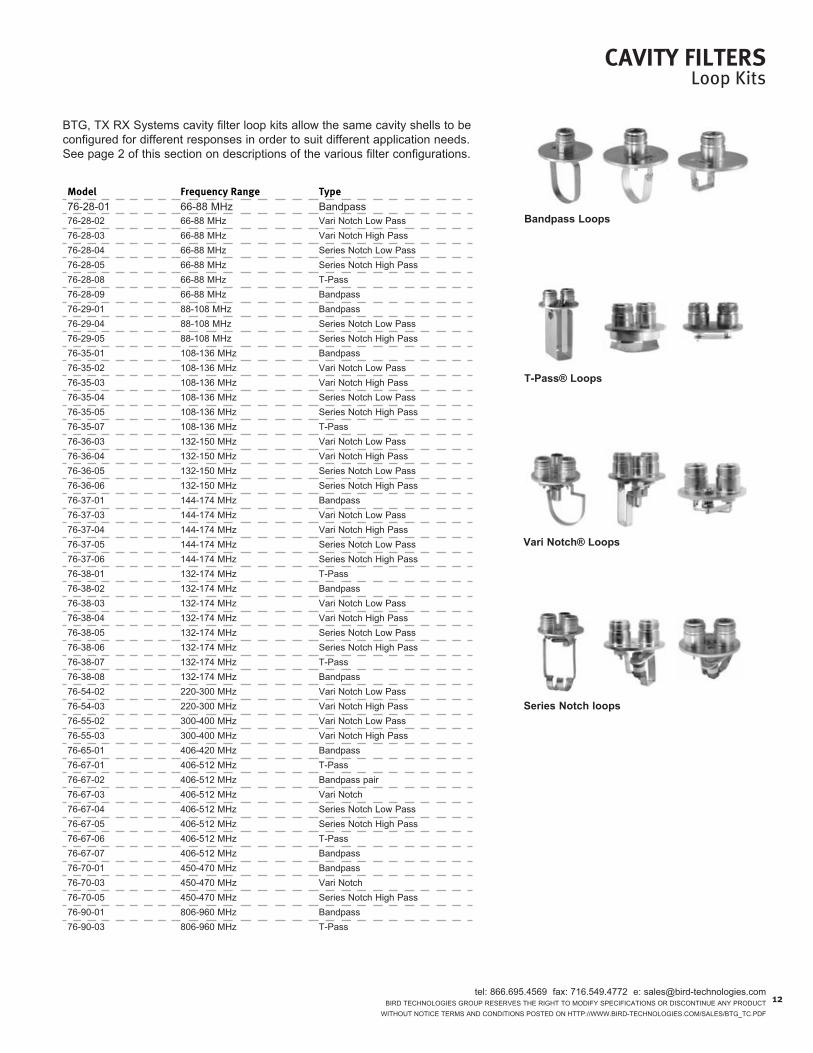
Model Frequency range type76-28-01 66-88 Mhz Bandpass76-28-02 66-88 Mhz Vari notch low pass76-28-03 66-88 Mhz Vari notch high pass76-28-04 66-88 Mhz series notch low pass76-28-05 66-88 Mhz series notch high pass76-28-08 66-88 Mhz T-pass76-28-09 66-88 Mhz Bandpass76-29-01 88-108 Mhz Bandpass76-29-04 88-108 Mhz series notch low pass76-29-05 88-108 Mhz series notch high pass76-35-01 108-136 Mhz Bandpass76-35-02 108-136 Mhz Vari notch low pass76-35-03 108-136 Mhz Vari notch high pass76-35-04 108-136 Mhz series notch low pass76-35-05 108-136 Mhz series notch high pass76-35-07 108-136 Mhz T-pass76-36-03 132-150 Mhz Vari notch low pass76-36-04 132-150 Mhz Vari notch high pass76-36-05 132-150 Mhz series notch low pass76-36-06 132-150 Mhz series notch high pass76-37-01 144-174 Mhz Bandpass76-37-03 144-174 Mhz Vari notch low pass76-37-04 144-174 Mhz Vari notch high pass76-37-05 144-174 Mhz series notch low pass76-37-06 144-174 Mhz series notch high pass76-38-01 132-174 Mhz T-pass76-38-02 132-174 Mhz Bandpass76-38-03 132-174 Mhz Vari notch low pass76-38-04 132-174 Mhz Vari notch high pass76-38-05 132-174 Mhz series notch low pass76-38-06 132-174 Mhz series notch high pass76-38-07 132-174 Mhz T-pass76-38-08 132-174 Mhz Bandpass76-54-02 220-300 Mhz Vari notch low pass76-54-03 220-300 Mhz Vari notch high pass76-55-02 300-400 Mhz Vari notch low pass76-55-03 300-400 Mhz Vari notch high pass76-65-01 406-420 Mhz Bandpass76-67-01 406-512 Mhz T-pass76-67-02 406-512 Mhz Bandpass pair76-67-03 406-512 Mhz Vari notch76-67-04 406-512 Mhz series notch low pass76-67-05 406-512 Mhz series notch high pass76-67-06 406-512 Mhz T-pass76-67-07 406-512 Mhz Bandpass76-70-01 450-470 Mhz Bandpass76-70-03 450-470 Mhz Vari notch76-70-05 450-470 Mhz series notch high pass76-90-01 806-960 Mhz Bandpass76-90-03 806-960 Mhz T-pass
BTg, TX rX systems cavity filter loop kits allow the same cavity shells to be configured for different responses in order to suit different application needs. see page 2 of this section on descriptions of the various filter configurations.
Bandpass Loops
T-Pass® Loops
Vari Notch® Loops
Series Notch loops
12

tel: 866.695.4569 fax: 716.549.4772 e: [email protected] Technologies group reserVes The righT To ModiFY speciFicATions or disconTinue AnY producT WiThouT noTice TerMs And condiTions posTed on hTTp://WWW.Bird-Technologies.coM/sAles/BTg_Tc.pdF
13
DuPlexers 30-960 MHz
38-36-01A38-37-01A
28-70-15h
A duplexer (or diplexer as they are sometimes called) is a 3-port device most commonly used to allow a transmitter and receiver, operating on different frequencies, to share a common antenna while operating simultaneously. The filters that make up the duplexer isolate the transmitter from the receiver by doing two important functions - the most important is filtering out any transmitter noise sidebands that are being generated on the receive frequency. The second function is protecting the receiver from transmitter carrier overload. The amount of isolation necessary is dependent upon the TX to rX frequency spacing. As the frequencies get closer, a higher value of isolation is required.
At high-band VhF and uhF, the TX rX Vari-notch® design is the most com-monly used. Vari-notch® provides a low-loss pseudo-bandpass characteristic that can exist very close to a deep notch. proven low-loss and low-noise con-struction techniques are used such as welded cavity construction; silver-plated loops, Alballoy®-plated integrated loop plates and connectors; as well as a unique fingerstock-free high-conductivity silver-plated tuning probe. our 4” and 6.625” diameter cavities are constructed of hardened aluminum which, unlike most copper cavities, resists denting and associated detuning.
At 700/800/900 Mhz where there are large guard bands and multiple frequen-cies per system, the Bandpass duplexer fills the bill nicely. The combline filter design is both low-loss and space-efficient. For duplexing a single repeater, the TX rX Vari-notch® design is still the product of choice. Vari-notch® provides a low-loss pseudo-bandpass characteristic that can exist very close to a deep notch. proven low-loss and low-noise construction techniques are used such as welded cavity construction; silver-plated loops, Alballoy®-plated integrated loop plates and connectors; as well as a unique fingerstock-free high-conductivity silver-plated tuning probe. our cavities are constructed of hardened aluminum which, unlike most copper cavities, resists denting and associated detuning.
28-52-02A28-56c-02A

tel: 866.695.4569 fax: 716.549.4772 e: [email protected] Technologies group reserVes The righT To ModiFY speciFicATions or disconTinue AnY producT
WiThouT noTice TerMs And condiTions posTed on hTTp://WWW.Bird-Technologies.coM/sAles/BTg_Tc.pdF
electrical: Temperature range: -30° to +60° cimpedance: 50 ohmsVsWr: 1.3:1
eleCtriCal MeCHaNiCalFrequency range(MHz)
Model Number MinimumFreq.separation(MHz)
Powerrating(W)
isolation(dB)*
insertionloss(dB)
No. ofCavities
Cavity size H(in)
W(in)
D(in)
tx & rx PortConnectors
antennaConnectors
shippingWeight(lbs)
30-40 28-13-01F 0.3 400 90 1.5 4 6.625” diA. 132 19 15 n n 25038-50 28-14-01F 0.3 400 90 1.5 4 6.625” diA. 101 19 15 n n 26050-54 28-25-92358 0.5 250 100 1.5/1.0 4 6.625” diA. 76/193 19 15 n n(F) 185
Tx high
Tx low
132-150 Tx high
Tx low
38-36-01A 4.5 100 70 0.9 4 2” sQ. 5.25 19 7.25 Bnc n 1030-36-01A 3.0 100 100 1.4/1.5 6 2” sQ. 5.25 19 7.25 Bnc n 1430-36-02A 3.0 100 100 1.4/1.5 6 2” sQ. 5.25 19 7.25 Bnc n 1474-36-02A 3.0 400 57 1.35 4 6.625” diA. 33 19 ±7.5 n n 5030-36-03A 1.5 100 80/90 1.4/2.2 6 2” sQ. 5.25 19 7.25 Bnc n 1430-36-04A 1.5 100 80/90 1.4/2.2 6 2” sQ. 5.25 19 7.25 Bnc n 1428-36-02A 0.5 400 85 1.5 4 6.625” diA. 33 19 ±7.5 n n 5028-36-11e 0.3 400 100 2.2 6 6.625” diA. 33 24 ±7.5 n n 75
Tx high
Tx low
144-174
Tx high Tx low
38-37-01A 4.5 100 70 0.9 4 2” sQ. 5.25 19 7.25 Bnc n 1030-37-01A 3.0 100 100 1.4/1.5 6 2” sQ. 5.25 19 7.25 Bnc n 1430-37-02A 3.0 100 100 1.4/1.5 6 2” sQ. 5.25 19 7.25 Bnc n 1428-37-07A 3.0 400 85 0.7 4 4” diA. 5.25 19 +4.5 -15.5 n n 22
28-37-07c 3.0 400 85 0.7 4 4” diA. 9.5 19 10.50 n n 2474-37-02A 3.0 400 57 1.35 4 6.625” diA. 33 19 ±7.5 n n 5030-37-03A 1.5 100 80/90 1.4/2.2 6 2” sQ. 5.25 19 7.25 Bnc n 1430-37-04A 1.5 100 80/90 1.4/2.2 6 2” sQ. 5.25 19 7.25 Bnc n 1428-37-06A 1.0 125 75 1.2 4 4” diA. 5.25 19 +4.5 -15.5 n n 2228-37-06c 1.0 125 75 1.2 4 4” diA. 9.5 19 10.5 n n 2428-37-04A 0.5 125 65 1.8 4 4” diA. 5.25 19 +4.5 -15.5 n n 2228-37-04c 0.5 125 65 1.8 4 4” diA. 9.5 19 10.5 n n 2428-37-02A 0.5 400 85 1.5 4 6.625” diA. 33 19 ±7.5 n n 5028-37-02A-din 0.5 400 85 1.5 4 6.625” diA. 33 19 ±7.5 n 7/16 din 5028-37-11e 0.3 400 100 2.2 6 6.625” diA. 33 24 ±7.5 n n 75
215-250 28-52-02A 1.6 250 90 1.2 4 4” diA. 5.25 19 +3 -15 n n 19380-420 28-56c-02A 3.0 350 80 0.8 4 4” diA. 5.25 19 +3-9 n n 19
406-430
28-65-01A 1.5 350 90 1.5 4 6.625” diA. 17 19 ±7.5 n n 3728-65-02A 3.0 350 80 0.8 4 4” diA. 5.25 19 +3-9 n n 1428-65-02B 3.0 350 80 0.8 4 4” diA. 5.25 19 12 n n 1628-65-05A 0.7 350 100 2.2 6 6.625” diA. 34 19 ±7.5 n n 7528-65-07A 3.0 250 85 1.25 4 4” diA. 5.25 19 +3-9 n n 1428-65-07B 3.0 250 85 1.25 4 4” diA. 5.25 19 12 n n 1628-65-08A 4.5 100 80 1.2 4 1.25” x 2” recT. 1.75 19 ±2.5 Bnc n 528-65-09A 2.5 100 80 1.8 6 1.25” x 2” recT. 3.5 19 ±2.5 Bnc n 728-65-10h 4.5 100 80 1.2 4 1.25” x 2” recT. 2.7 5.12 7.4 Bnc uhF 5
442-450
26-66-01A 6.0 100 70 1.2 2 coMBline 10 21.5 7.5 n n 1228-66-02A 5.0 350 100 0.6 4 4” diA. 5.25 19 +3-9 n n 1428-66-02B 5.0 350 100 0.6 4 4” diA. 5.25 19 12 n n 1628-66-04h 5.0 100 80 1.2 4 1.25” x 2” recT. 2.7 5.12 7.4 n uhF 5
450-470
28-70-01A 1.5 350 90 1.5 4 6.625” diA. 17 19 ±7.5 n n 3728-70-02A 5.0 350 100 0.6 4 4” diA. 5.25 19 +3-9 n n 1428-70-02B 5.0 350 100 0.6 4 4” diA. 5.25 19 12 n n 1628-70-07A 0.7 350 100 2.2 6 6.625” diA. 34 19 ±7.5 n n 5528-70-09A 5.0 250 100 1.25 4 4” diA. 5.25 19 +3-9 n n 1428-70-09B 5.0 250 100 1.25 4 4” diA. 5.25 19 12 n n 1628-70-14A 5.0 100 80 1.2 4 1.25” x 2” recT. 1.75 19 ±2.5 Bnc n 528-70-15h 5.0 100 80 1.2 4 1.25” x 2” recT. 2.7 5.12 7.4 Bnc uhF 5
DuPlexersTechnical Specifications
30-512 MHz
*specifications for duplexers of unsymmetrical construction or response are listed as follows: isolation: noise suppression/carrier suppressioninsertion loss: Tx loss/rx loss
14

tel: 866.695.4569 fax: 716.549.4772 e: [email protected] Technologies group reserVes The righT To ModiFY speciFicATions or disconTinue AnY producT WiThouT noTice TerMs And condiTions posTed on hTTp://WWW.Bird-Technologies.coM/sAles/BTg_Tc.pdF
15
DuPlexersTechnical Specifications764-1300 MHz
eleCtriCal MeCHaNiCal
Frequency range(MHz)
Model Number MinimumFreq.separation(MHz)
Powerrating(Watts)
isolation(dB)*
insertionloss (dB)
No. ofCavities
Cavity size H” W” D” tx & rxPortConnectors
antennaConnectors
shippingWeight(lbs.)
470-512
28-69-01A 1.5 350 90 1.5 4 6.625” diA. 17 19 ±7.5 n n 37
28-69-02A 3.0 350 80 0.8 4 4” diA. 5.25 19 +3-9 n n 14
28-69-02B 3.0 350 80 0.8 4 4” diA. 5.25 19 12 n n 16
28-69-04A 0.7 350 100 2.2 6 6.625” diA. 34 19 ±7.5 n n 55
764-806
28-83e-01A 30 125 60/90 0.8/0.8 4 4” diA. 5.25 19 +3-6.5 n n 10
28-83e-01B 30 125 60/90 0.8/0.8 4 4” diA. 5.25 19 10 n n 10
806-869
26-89-03A 45 600 45/77 0.5/1.0 n/A coMBline 5.25 19 +7-2 n n 14
26-89A-01A 45 600 35/90 0.5/1.5 n/A coMBline 5.25 19 +7-2 n n 15
26-89A-05A 45 600 35/110 0.5/1.0 n/A coMBline 5.25 19 +7-2 n n 16
28-89-01A 45 125 90/90 0.8/0.8 4 4” diA. 5.25 19 +3-6.5 n n 10
28-89-01B 45 125 90/90 0.8/0.8 4 4” diA. 5.25 19 10 n n 12
890-960
26-88-01A 39 600 55/100 0.6/1.2 4 coMBline & 4” diA. 5.25 19 +7-6.5 n n 15
28-88-01A 3.6 125 90/90 1.25/1.25 4 4” diA. 5.25 19 +3-6.5 n n 10
28-88-01B 3.6 125 90/90 1.25/1.25 4 4” diA. 5.25 19 10 n n 12
28-88-04A 39 125 90/90 0.8/0.8 4 4” diA. 5.25 19 +3-6.5 n n 10
28-88-04B 39 125 90/90 0.8/0.8 4 4” diA. 5.25 19 10 n n 12
1215-130028-97-01A 12 125 100 1.0 4 4” diA. 5.25 19 +3-6.5 n n 13
28-97-01B 12 125 100 1.0 4 4” diA. 5.25 19 10 n n 13
1.2 -1.3 ghz 36-97-07053-A 12 100 50 1.3/1.3 4 4” diA. 10.5 19 8.9 n n 13
*specifications for duplexers of unsymmetrical construction or response are listed as follows:isolation: noise suppression/carrier suppressioninsertion loss: Tx loss/rx loss
general specificationselectrical: Temperature range: -30° to + 60° cimpedance: 50 ohms, VsWr: 1.3:1
tel: 866.695.4569 fax: 716.549.4772 e: [email protected] Technologies group reserVes The righT To ModiFY speciFicATions or disconTinue AnY producT
WiThouT noTice TerMs And condiTions posTed on hTTp://WWW.Bird-Technologies.coM/sAles/BTg_Tc.pdF
reFereNCeDuplexer Trouble Shooting Aid
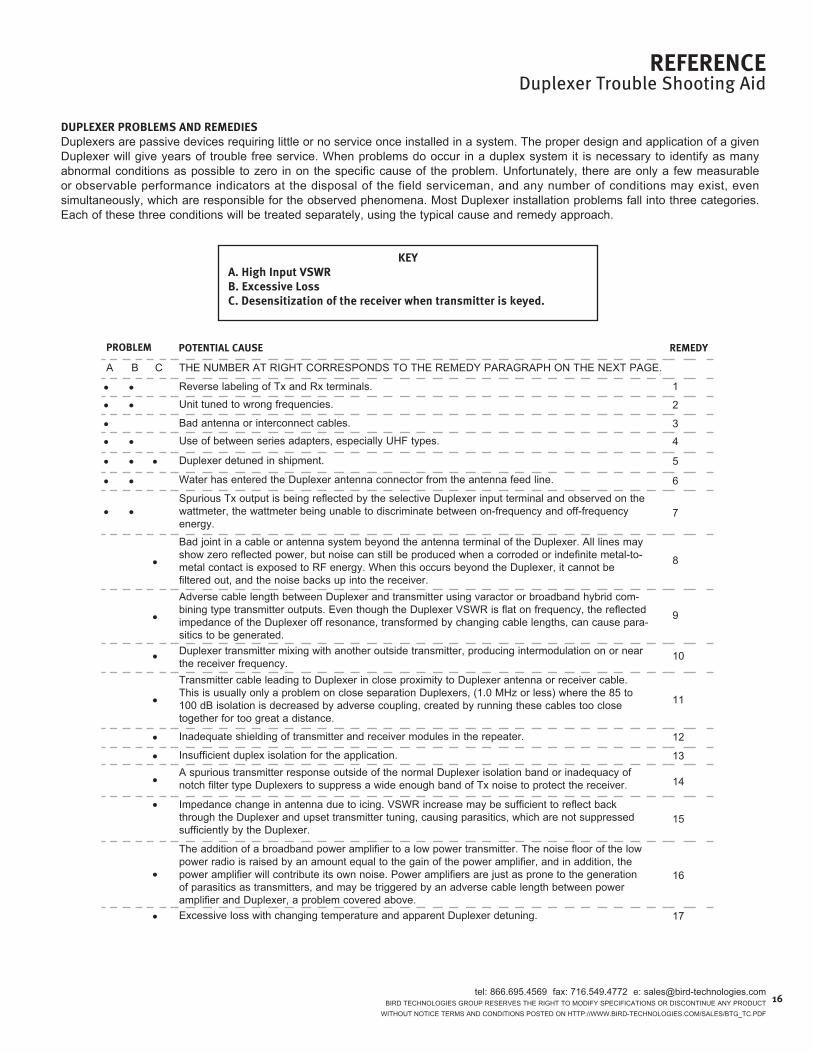
DuPlexer PrOBleMs aND reMeDiesduplexers are passive devices requiring little or no service once installed in a system. The proper design and application of a given duplexer will give years of trouble free service. When problems do occur in a duplex system it is necessary to identify as many abnormal conditions as possible to zero in on the specific cause of the problem. unfortunately, there are only a few measurable or observable performance indicators at the disposal of the field serviceman, and any number of conditions may exist, even simultaneously, which are responsible for the observed phenomena. Most duplexer installation problems fall into three categories. each of these three conditions will be treated separately, using the typical cause and remedy approach.
Keya. High input vsWrB. excessive lossC. Desensitization of the receiver when transmitter is keyed.
PrOBleM POteNtial Cause reMeDy
A B c The nuMBer AT righT corresponds To The reMedY pArAgrAph on The neXT pAge.
• • reverse labeling of Tx and rx terminals. 1
• • unit tuned to wrong frequencies. 2
• Bad antenna or interconnect cables. 3
• • use of between series adapters, especially uhF types. 4
• • • duplexer detuned in shipment. 5
• • Water has entered the duplexer antenna connector from the antenna feed line. 6
• • spurious Tx output is being reflected by the selective duplexer input terminal and observed on the wattmeter, the wattmeter being unable to discriminate between on-frequency and off-frequency energy.
7
• Bad joint in a cable or antenna system beyond the antenna terminal of the duplexer. All lines may show zero reflected power, but noise can still be produced when a corroded or indefinite metal-to- metal contact is exposed to rF energy. When this occurs beyond the duplexer, it cannot be filtered out, and the noise backs up into the receiver.
8
• Adverse cable length between duplexer and transmitter using varactor or broadband hybrid com- bining type transmitter outputs. even though the duplexer VsWr is flat on frequency, the reflected impedance of the duplexer off resonance, transformed by changing cable lengths, can cause para- sitics to be generated.
9
• duplexer transmitter mixing with another outside transmitter, producing intermodulation on or near the receiver frequency.
10
• Transmitter cable leading to duplexer in close proximity to duplexer antenna or receiver cable. This is usually only a problem on close separation duplexers, (1.0 Mhz or less) where the 85 to 100 dB isolation is decreased by adverse coupling, created by running these cables too close together for too great a distance.
11
• inadequate shielding of transmitter and receiver modules in the repeater. 12
• insufficient duplex isolation for the application. 13
• A spurious transmitter response outside of the normal duplexer isolation band or inadequacy of notch filter type duplexers to suppress a wide enough band of Tx noise to protect the receiver. 14
• impedance change in antenna due to icing. VsWr increase may be sufficient to reflect back through the duplexer and upset transmitter tuning, causing parasitics, which are not suppressed sufficiently by the duplexer.
15
•
The addition of a broadband power amplifier to a low power transmitter. The noise floor of the low power radio is raised by an amount equal to the gain of the power amplifier, and in addition, the power amplifier will contribute its own noise. power amplifiers are just as prone to the generation of parasitics as transmitters, and may be triggered by an adverse cable length between power amplifier and duplexer, a problem covered above.
16
• excessive loss with changing temperature and apparent duplexer detuning. 17
16

tel: 866.695.4569 fax: 716.549.4772 e: [email protected] Technologies group reserVes The righT To ModiFY speciFicATions or disconTinue AnY producT WiThouT noTice TerMs And condiTions posTed on hTTp://WWW.Bird-Technologies.coM/sAles/BTg_Tc.pdF
17
1. Tune a signal generator to the receive frequency and inject it into the antenna terminal, sampling for the signal at each equipment terminal. reverse the labels if necessary. it may be that the unit was ordered to the reverse frequencies. if so, the label will indicate this. if the duplexer is symmetri-cal in design (usually indicated by the same number of Tx and rx filter sections) just reverse the equipment labels and operate. generally, no damage will be done to the duplexer when operated in reverse for a short time period. if other adverse symptoms appear, contact the factory.
2. check the unit label. if needed, the duplexer may be fieldtuned. consult the instructions and/or the factory if the duplexer is still under warranty or beyond field tuning capa-bility.
3. check cable, by substitution, using a termaline wattmeter, or a thruline wattmeter into a known good load. check the antenna line input for reflected power.
4. To eliminate high input VsWr reduce the number of between series adapters by making up proper interconnect cables. uhF connectors are non-constant impedance, and certain combinations can transform a 1.1:1 VsWr into a 2.0:1, or vice versa.
5. consult the instruction manual for field tuning procedures, or the factory, if the unit is still under warranty or beyond field tuning capability. (We trust that our products will not be prone to this problem).
6. consult the factory. The affected antenna cables may be field replaceable, or a “baking out” process may be possible.
7. To prove this condition, place a bandpass filter between the Tx and duplexer to clean up the spurious, and put the wattmeter between the bandpass filter and the duplexer to measure reflected power from the duplexer. The bandpass filter selectivity should be equal to or better than that of the duplexer at about the 3.0 dB points.
8. operate the duplex system into a dummy load. if no desensitization occurs, check out all lines, antennas, and look for potential bad joints close to the radiating antenna where re-radiation of noise may be possible back into the antenna system receiver. loose metal-to-metal contacts on tower guying systems have also been known to create sys-tem noise. note the effect of vibrating tower guys on system noise.
9. change the length of cable between the transmitter andduplexer, traversing through a half wave in increments of between 1 and 2 inches until the desensitization ceases or is minimal. A ferrite isolator will also cure this condition when it is installed between the transmitter and duplexer. however, this is a much more expensive remedy.
10. if the iM is in the duplex transmitter, a ferrite isolator in the duplex transmitter line (noT antenna line) will show this by either reducing or eliminating it. More isolation can be obtained by cascading isolators if needed. however, iM of this magnitude indicates the system should be studied for possible revision to reduce the production of this iM.
11. cables such as rg-8a/u and rg-213/u should be kept at least 3-4” apart over 5’-10’ runs. use of double shielded cable will reduce the susceptibility to this problem.
12. consult the radio manufacturer. This condition can be verified by operating the transmitter into a dummy load while injecting a minimum quieting signal into the receiver. some radios require special modifications before they are suitable for repeater operation.
13. if this problem is suspected, contact the radio manufac-turer for recommended duplex isolation for Tx noise suppres-sion and carrier suppression. duplexer isolation should be measured first per instruction manual to verify rated specifi-cations are present. if more duplex isolation is required, con-tact TX rX sYsTeMs for recommended filtering.
14. consult the factory. Bandpass filter tests can be made toconfirm this. in extreme cases, adjustments to the transmitter may be required.
15. either de-ice the antenna, or use an antenna less sensi-tive to ice. A ferrite isolator can also be put at the transmitter output to improve the impedance match. Ferrite isolators can-not be put in antenna lines, as they will attenuate rx signals.
16. A mismatch may possibly be reduced by lengthening the cable which runs between the power amplifier output and the duplexer input until the receiver desensitization disappears, as follows:30 Mhz to 512 Mhz rAngeBnc or n type adapters may be inserted in the original cable, one at a time and not to exceed a total of 1/2 wave-length, until desensitization disappears.800 Mhz to 1.3 ghz rAngeprepare a cable length 3/4” longer than the original cable andinsert. if desensitization does not disappear, repeat with cables each 3/4” longer than the previous length, not to exceed 1/2 wavelength.
17. We find that this cause most commonly relates to shiftingimpedance of the transmitter or power amplifier with tem-perature. The duplexer appears detuned, since a “conjugate match” (canceling reactance, and matching resistance com-ponent) is approached by shifting the duplexer passband above or below the 50 ohm point, as determined by an increase in output power on the wattmeter. in this case, tem-perature control of the room is the only answer, other than upgrading the transmitter.
FielD serviCe reMeDies FOr PrOBleMs listeD ON PreviOus PaGe
reFereNCeDuplexer Trouble Shooting Aid

tel: 866.695.4569 fax: 716.549.4772 e: [email protected] Technologies group reserVes The righT To ModiFY speciFicATions or disconTinue AnY producT
WiThouT noTice TerMs And condiTions posTed on hTTp://WWW.Bird-Technologies.coM/sAles/BTg_Tc.pdF
isOlatiON Curves FOr Data reFereNCe traNsMitter/reCeiverThe curves shown below for use with filters, duplexers, and multicouplers, indicate the amount of isolation or attenuation required between a typical 100 watt transmitter and its associated receiver at the Tx (carrier suppression) and rx (noise suppression) frequency which will result in no more than a 1 db degradation of the 12 db sinAd sensitivity.
note: These are only “typical curves. When accuracy is required, consult the radio manufacturer.
reFereNCeTNRD Curves
18

tel: 866.695.4569 fax: 716.549.4772 e: [email protected] Technologies group reserVes The righT To ModiFY speciFicATions or disconTinue AnY producT WiThouT noTice TerMs And condiTions posTed on hTTp://WWW.Bird-Technologies.coM/sAles/BTg_Tc.pdF
19
reFereNCeLoss Nomographs
REFLECTED POWER (WATTS)
REFLECTED POWER (WATTS)
FOR
WA
RD
PO
WER
(WA
TTS)
OUTPUT POWER (WATTS)
INPU
T PO
WER
(WA
TTS)
INSERTION LOSS (Db)
BTg, TX rX systems offers this convenient means of determining ten insertion loss of Filter, duplexers, Multicouplers, and related products. it should be remembered that the field accuracy of wattmeter readings is subject to considerable variance due to rF connector VsWr and basic wattmeter accuracy, particularly at low end scale readings. however, allowing for these variances, this graph should prove to be a useful reference.
For lower power levels, divide both scales by 10 (5 to 50 watts)
For other power levels, multiply both scales by the same multiplier

tel: 866.695.4569 fax: 716.549.4772 e: [email protected] Technologies group reserVes The righT To ModiFY speciFicATions or disconTinue AnY producT
WiThouT noTice TerMs And condiTions posTed on hTTp://WWW.Bird-Technologies.coM/sAles/BTg_Tc.pdF
reFereNCedB Conversion
CONversiON taBle
poWer And VolTAge rATios To dBTo AccounT For The sign oF The deciBelFor positive (+) values of the decibel - Both voltage and power ratios are greater than unity. use the two right hand columns.For negative (-) values of the decibel - Both voltage and power ratios are less than unity. use the two left hand columns.
voltageratio
Powerratio <-- - dB + -->
voltageratio
Powerratio
1.0000 1.0000 0 1.0000 1.00000.9886 0.9772 0.1 1.0116 1.02330.9772 0.9550 0.2 1.0233 1.04710.9661 0.9333 0.3 1.0351 1.07150.9550 0.9120 0.4 1.0471 1.09650.9441 0.8913 0.5 1.0593 1.12200.9333 0.8710 0.6 1.0715 1.14820.9226 0.8511 0.7 1.0839 1.17490.9120 0.8318 0.8 1.0965 1.20230.9016 0.8128 0.9 1.1092 1.23030.8913 0.7943 1 1.1220 1.25890.8810 0.7762 1.1 1.1350 1.28820.8710 0.7586 1.2 1.1482 1.31830.8610 0.7413 1.3 1.1614 1.34900.8511 0.7244 1.4 1.1749 1.38040.8414 0.7079 1.5 1.1885 1.41250.8318 0.6918 1.6 1.2023 1.44540.8222 0.6761 1.7 1.2162 1.47910.8128 0.6607 1.8 1.2303 1.51360.8035 0.6457 1.9 1.2445 1.54880.7943 0.6310 2 1.2589 1.58490.7852 0.6166 2.1 1.2735 1.62180.7762 0.6026 2.2 1.2882 1.65960.7674 0.5888 2.3 1.3032 1.69820.7586 0.5754 2.4 1.3183 1.73780.7499 0.5623 2.5 1.3335 1.77830.7413 0.5495 2.6 1.3490 1.81970.7328 0.5370 2.7 1.3646 1.86210.7244 0.5248 2.8 1.3804 1.90550.7161 0.5129 2.9 1.3964 1.94980.7079 0.5012 3 1.4125 1.99530.6998 0.4898 3.1 1.4289 2.04170.6918 0.4786 3.2 1.4454 2.08930.6839 0.4677 3.3 1.4622 2.1380
voltageratio
Powerratio <-- - dB + -->
voltageratio
Powerratio
0.6761 0.4571 3.4 1.4791 2.18780.6683 0.4467 3.5 1.4962 2.23870.6607 0.4365 3.6 1.5136 2.29090.6531 0.4266 3.7 1.5311 2.34420.6457 0.4169 3.8 1.5488 2.39880.6383 0.4074 3.9 1.5668 2.45470.6310 0.3981 4 1.5849 2.51190.6237 0.3890 4.1 1.6032 2.57040.6166 0.3802 4.2 1.6218 2.63030.6095 0.3715 4.3 1.6406 2.69150.6026 0.3631 4.4 1.6596 2.75420.5957 0.3548 4.5 1.6788 2.81840.5888 0.3467 4.6 1.6982 2.88400.5821 0.3388 4.7 1.7179 2.95120.5754 0.3311 4.8 1.7378 3.02000.5689 0.3236 4.9 1.7579 3.09030.5623 0.3162 5 1.7783 3.16230.5559 0.3090 5.1 1.7989 3.23590.5495 0.3020 5.2 1.8197 3.31130.5433 0.2951 5.3 1.8408 3.38840.5370 0.2884 5.4 1.8621 3.46740.5309 0.2818 5.5 1.8836 3.54810.5248 0.2754 5.6 1.9055 3.63080.5188 0.2692 5.7 1.9275 3.71540.5129 0.2630 5.8 1.9498 3.80190.5070 0.2570 5.9 1.9724 3.89050.5012 0.2512 6 1.9953 3.98110.4955 0.2455 6.1 2.0184 4.07380.4898 0.2399 6.2 2.0417 4.16870.4842 0.2344 6.3 2.0654 4.26580.4786 0.2291 6.4 2.0893 4.36520.4732 0.2239 6.5 2.1135 4.46680.4677 0.2188 6.6 2.1380 4.57090.4624 0.2138 6.7 2.1627 4.6774
voltageratio
Powerratio <-- - dB + -->
voltageratio
Powerratio
0.4571 0.2089 6.8 2.1878 4.78630.4519 0.2042 6.9 2.2131 4.89780.4467 0.1995 7 2.2387 5.01190.4416 0.1950 7.1 2.2646 5.12860.4365 0.1905 7.2 2.2909 5.24810.4315 0.1862 7.3 2.3174 5.37030.4266 0.1820 7.4 2.3442 5.49540.4217 0.1778 7.5 2.3714 5.62340.4169 0.1738 7.6 2.3988 5.75440.4121 0.1698 7.7 2.4266 5.88840.4074 0.1660 7.8 2.4547 6.02560.4027 0.1622 7.9 2.4831 6.16600.3981 0.1585 8 2.5119 6.30960.3936 0.1549 8.1 2.5410 6.45650.3890 0.1514 8.2 2.5704 6.60690.3846 0.1479 8.3 2.6002 6.76080.3802 0.1445 8.4 2.6303 6.91830.3758 0.1413 8.5 2.6607 7.07950.3715 0.1380 8.6 2.6915 7.24440.3673 0.1349 8.7 2.7227 7.41310.3631 0.1318 8.8 2.7542 7.58580.3589 0.1288 8.9 2.7861 7.76250.3548 0.1259 9 2.8184 7.94330.3508 0.1230 9.1 2.8510 8.12830.3467 0.1202 9.2 2.8840 8.31760.3428 0.1175 9.3 2.9174 8.51140.3388 0.1148 9.4 2.9512 8.70960.3350 0.1122 9.5 2.9854 8.91250.3311 0.1096 9.6 3.0200 9.12010.3273 0.1072 9.7 3.0549 9.33250.3236 0.1047 9.8 3.0903 9.54990.3199 0.1023 9.9 3.1261 9.77240.3162 0.1000 10 3.1623 10.00000.1778 0.0316 11 5.6234 31.6228
20

tel: 866.695.4569 fax: 716.549.4772 e: [email protected] Technologies group reserVes The righT To ModiFY speciFicATions or disconTinue AnY producT WiThouT noTice TerMs And condiTions posTed on hTTp://WWW.Bird-Technologies.coM/sAles/BTg_Tc.pdF
reFereNCePower Conversion Chart & Free Space Path Loss
Power Conversion ChartdBm to dBw to Watts to volts
dBm dBw Watts Volts (50 ohm)80 50 100 kW 223675 45 31.6 kW 125770 40 10.0 kW 70765 35 3.16 kW 39860 30 1000 22455 25 316 12650 20 100 70.745 15 31.6 39.840 10 10.0 22.438 8 6.31 17.836 6 3.98 14.134 4 2.51 11.232 2 1.58 8.9030 0 1.00 7.0729 -1 0.79 6.3028 -2 0.63 5.6227 -3 0.50 5.0126 -4 0.40 4.4625 -5 0.32 3.9824 -6 0.25 3.5423 -7 0.20 3.1622 -8 0.16 2.8221 -9 0.13 2.5120 -10 0.10 2.2419 -11 79 mW 1.99
Power Conversion ChartdBm to dBw to Watts to volts
dBm dBm Watts Volts (50 ohm)18 -12 63 mW 1.7817 -13 50 mW 1.5816 -14 40 mW 1.4115 -15 32 mW 1.2614 -16 25 mW 1.1213 -17 20 mW 1.0012 -18 16 mW 0.89011 -19 13 mW 0.79310 -20 10 mW 0.7079 -21 7.9 mW 0.6308 -22 6.3 mW 0.5627 -23 5.0 mW 0.5016 -24 4.0 mW 0.4465 -25 3.2 mW 0.3984 -26 2.5 mW 0.3543 -27 2.0 mW 0.3162 -28 1.6 mW 0.2821 -29 1.3 mW 0.2510 -30 1.0 mW 0.224-5 -35 316 uW 0.126-10 -40 100 uW 0.071-15 -45 31.6 uW 0.040-20 -50 10 uW 0.022-25 -55 3.16 uW 0.013-30 -60 1 uW 0.007
21

tel: 866.695.4569 fax: 716.549.4772 e: [email protected] Technologies group reserVes The righT To ModiFY speciFicATions or disconTinue AnY producT
WiThouT noTice TerMs And condiTions posTed on hTTp://WWW.Bird-Technologies.coM/sAles/BTg_Tc.pdF
path length(miles)
path loss in dB: Frequency in Mhz
50 150 170 450 500 800 9000.1 50.58 60.12 61.21 69.66 70.58 74.66 75.680.25 58.54 68.08 69.17 77.62 78.54 82.62 83.640.5 64.56 74.10 75.19 83.64 84.56 88.64 89.661 70.58 80.12 81.21 89.66 90.58 94.66 95.682 76.60 86.14 87.23 95.68 96.60 100.68 101.713 80.12 89.66 90.75 99.21 100.12 104.20 105.234 82.62 92.16 93.25 101.71 102.62 106.70 107.735 84.56 94.10 95.19 103.64 104.56 108.64 109.666 86.14 95.68 96.77 105.23 106.14 110.22 111.257 87.48 97.02 98.11 106.57 107.48 111.56 112.598 88.64 98.18 99.27 107.73 108.64 112.72 113.759 89.66 99.21 100.29 108.75 109.66 113.75 114.7710 90.58 100.12 101.21 109.66 110.58 114.66 115.6812 92.16 101.71 102.79 111.25 112.16 116.25 117.2714 93.50 103.04 104.13 112.59 113.50 117.58 118.6116 94.66 104.20 105.29 113.75 114.66 118.74 119.7718 95.68 105.23 106.31 114.77 115.68 119.77 120.7920 96.60 106.14 107.23 115.68 116.60 120.68 121.7130 100.12 109.66 110.75 119.21 120.12 124.20 125.2340 102.62 112.16 113.25 121.71 122.62 126.70 127.7350 104.56 114.10 115.19 123.64 124.56 128.64 129.66
Free sPaCe PatH lOss estiMatOr
ForMulA: path loss (dB) = 36.6 + 20 log (Mhz) + 20 log (miles)
22
reFereNCeFree Space Path Loss

Cavity Filters & DuplexersYou’re heard, loud and clear.
Bird® Technologies Group (BTG) is a global, innovative supplier
of RF products, systems, services and educational solutions.
Combining the industry leading brands of both Bird Electronic
and TX RX Systems in one company reinforces the BTG
commitment to providing RF Measurement and Management in
Your World.
Our portfolio includes hardware, software, components and services. We
offer these innovative products and services through our industry lead-
ing product line brands, Bird Electronic Corp and TX RX Systems. We
provide test instruments that are highly accurate, rugged and easy to
use. Industry leading components and products such as site analyzers,
wattmeters, digital sensors, samplers, antennas, signal boosters,
and tower mounted amplifiers. Furthermore, we offer dependable
engineering, calibration and educational services for land mobile radio,
cellular, semiconductor, broadcast, medical, military and government
applications.
All BTG products can be serviced and calibrated by the Bird Service
Center (BSC). BSC provides a full range of service and support. With over
130 years of combined product and calibration experience, our service
technicians and product experts offer reliable service and customer care.
Bird Service Centers and Service Partners are located World Wide
providing a full range of service and support for your Bird Products.
Catalogs offered by Bird Technologies Group(To view or download go to www.bird-technologies.com)
Bird General Catalog
RF & Microwave Components Catalog
Transmit Combiners Catalog
Cavity Filters & Duplexers Catalog
Antennas Catalog
Tower Top Amplifiers, Receiver Multicouplers & Preselectors Catalog
Isolators & Loads Catalog
In-Building Coverage Catalog (Signal Boosters & Accessories)
Bird® Technologies Group combines the industry leading brands of both Bird Electronic and TX RX Systems and is a global, innovative supplier of RF products,systems, services and educational solutions. Bird® Technologies Group reserved the right to modify specifications or discontinue any product without notice.
You’re heard, loud and clear.
30303 Aurora Rd. :: Solon, OH 44139 :: 866.695.4569 :: www.bird-technologies.com
©2009 Bird Technologies GroupCavDup-10142009