cav controllers 47504 neukirchen-vluyn trox gmbh
TRANSCRIPT
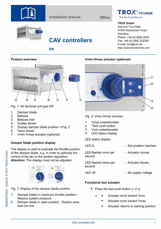
Product overview
Fig. 1: Air terminal unit type EN
1 Damper blade2 Bellows3 Bellows inlet4 Scales sticker5 Display damper blade position ðFig. 26 Hand wheel7 Vmin-/Vmax actuator (optional)
Damper blade position display
The display is used to evaluate the throttle positionof the damper blade, e.g. in order to optimise thecontrol of the fan or the section regulation.Attention: The display must not be adjusted.
Fig. 2: Display of the damper blade position
1 Damper blade in maximum throttle position -Reduce system pressure
2 Damper blade in open position - System pres-sure too low
Vmin-/Vmax actuator (optional)
Fig. 3: Vmin-/Vmax actuator
1 Vmax potentiometer2 'Test' push button3 Vmin potentiometer4 LED status display
LED status display:
LED lit - Set position reached
LED flashes once persecond
- Actuator moves
LED flashes twice persecond
- Actuator blocks
LED off - No supply voltage
Functional test actuator
Press the test push button (> 2 s)
ð Actuator turns toward Vmin Actuator turns toward Vmax Actuator returns to starting position
Installation manual GB/en
CAV controllersEN
TROX GmbHHeinrich-Trox-Platz47504 Neukirchen-VluynGermanyPhone: +49 (0) 2845 2020Fax: +49 (0) 2845 202265E-mail: [email protected]://www.troxtechnik.com
A000
0007
5031
, 12/
2019
, © 2
017
TRO
X G
mbH
CAV controllers EN 1

Important notes
Information on the installation manual
This manual enables operating or service personnelto correctly install the product described below andto use it safely and efficiently.
It is essential that these individuals read and fullyunderstand this manual before starting any work.The basic prerequisite for safe working is to complywith the safety notes and all instructions in thismanual.
The local regulations for health and safety at workand general safety regulations also apply.
Correct use
CAV controllers of the type EN are used for con-stant volume flow control in supply and extract airducts of ventilation and ventilation systems.
Do not use CAV controllers in extract air systems incommercial kitchens unless the extract air has beencleaned as much as possible with high-efficiencyaerosol separators; see VDI 2052.
The installation of air terminal devices in humidrooms, areas with potentially explosive atmos-pheres or rooms with dust-laden or aggressive airhas to be assessed for each individual case.
TROX Technical Service
To ensure that your request is processed as quicklyas possible, please keep the following informationready:
Product name TROX order number Delivery date Brief description of the fault
Online www.troxtechnik.com
Phone +49 2845 202-400
Qualified staff
HVAC technicianHVAC technicians are individuals who have suffi-cient professional or technical training in the fieldthey are working in to enable them to carry out theirassigned duties at the level of responsibility allo-cated to them and in compliance with the relevantguidelines, safety regulations and instructions.HVAC technicians are individuals who have in-depth knowledge and skills related to HVAC sys-tems; they are also responsible for the professionalcompletion of the work under consideration.
HVAC technicians are individuals who have suffi-cient professional or technical training, knowledgeand actual experience to enable them to work onHVAC systems, understand any potential hazardsrelated to the work under consideration, and recog-nise and avoid any risks involved.
Skilled qualified electricianSkilled qualified electricians are individuals whohave sufficient professional or technical training,knowledge and actual experience to enable them towork on electrical systems, understand any poten-tial hazards related to the work under consideration,and recognise and avoid any risks involved.
Personal protective equipment
Personal protective equipment must be worn forany work in order to reduce health or safety haz-ards to the minimum.
The appropriate protective equipment for a job mustbe worn for as long as the job takes.
Industrial safety helmet
Industrial safety helmets protect the head fromfalling objects, suspended loads, and the effects ofstriking the head against stationary objects.
Important notes
CAV controllers EN2

Protective gloves
Protective gloves protect hands from friction, abra-sions, punctures, deep cuts, and direct contact withhot surfaces.
Safety shoes
Safety shoes protect the feet against crushing,falling parts, and slipping on slippery ground.
Limitation of liability
The information in this manual has been compiledwith reference to the applicable standards andguidelines, the state of the art, and our expertiseand experience of many years.
The manufacturer does not accept any liability fordamages resulting from:
Non-compliance with this manual Incorrect use Operation or handling by untrained individuals Unauthorised modifications
The actual scope of delivery may differ from theinformation in this manual for special constructions,additional order options or as a result of recenttechnical changes.
Transport and storage
Delivery check
Upon delivery, carefully remove the packaging andcheck the unit for transport damage and complete-ness. In case of any damage or an incomplete ship-ment, contact the shipping company and your sup-plier immediately. Put the product back into itspackaging after the delivery check to protect it fromdust and contamination.
Fixing and installation material
Fixing and installation material is not part of thesupply package (unless stated otherwise), buthas to be provided by others; it has to be suitablefor the installation situation.
Transport on site
CAUTION!
Danger of injury from sharp edges, sharp cor-ners and thin sheet metal parts!Sharp edges, sharp corners and thin sheet metalparts may cause cuts or grazes.
– Be careful when carrying out any work.– Wear protective gloves, safety shoes and a
hard hat.
Please note:
Be careful when unloading or moving theproduct, and pay attention to the symbols andinformation on the packaging.
If possible, take the product in its transportpackaging up to the installation location.
Use only lifting and transport gear designed forthe required load.
Always secure the load against tipping andfalling.
Transport and storage
CAV controllers EN 3

Do not move bulky items just by yourself. Gethelp to prevent injuries and damage.
Only lift or hold the control unit at the housing,not at the damper blade, at the flow rateadjustment or at the actuator.
Storage
Please note:
Store the product only in its original packaging Protect the product from the effects of weather
Protect the product from humidity, dust andcontamination
Storage temperature: -10 °C to 50 °C. Relative humidity: 95% max., no condensation
Packaging
Properly dispose of packaging material.
Technical dataNominal sizes 200 × 100 to 600 × 600 mm
Volume flow rate range 39 – 3500 l/s or 140 – 12600 m³/h
Volume flow rate controlrange
Approx. 25 to 100% of thenominal volume flow rate
Scale accuracy ± 4%
Minimum differential pres-sure
50 Pa
Maximum differential pres-sure
1000 Pa
Operating temperature 10 – 50 °C
Technical data actuator
Actuator E01 E02 E03
Supply voltage 24 VAC/DC
230 VAC/DC
24 VAC/DC
Mains frequency AC: 50/60 Hz
Power rating DC: 2.5 W; AC: 4.5 VA
Protection level IP42
IEC protectionclass
III II III
Setpoint valuesignal input
– – 0 – 10 VDC, Ra >100 kΩ
Actual valuesignal output
– – 0 – 10 V DC,
max. 0.5 mA
Ambient temper-ature
10-50 °C
Ambient humidity 5-90% rF
Technical data
CAV controllers EN4
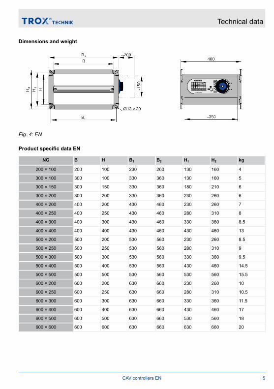
Dimensions and weight
Fig. 4: EN
Product specific data EN
NG B H B1 B2 H1 H2 kg
200 × 100 200 100 230 260 130 160 4
300 × 100 300 100 330 360 130 160 5
300 × 150 300 150 330 360 180 210 6
300 × 200 300 200 330 360 230 260 6
400 × 200 400 200 430 460 230 260 7
400 × 250 400 250 430 460 280 310 8
400 × 300 400 300 430 460 330 360 8.5
400 × 400 400 400 430 460 430 460 13
500 × 200 500 200 530 560 230 260 8.5
500 × 250 500 250 530 560 280 310 9
500 × 300 500 300 530 560 330 360 9.5
500 × 400 500 400 530 560 430 460 14.5
500 × 500 500 500 530 560 530 560 15.5
600 × 200 600 200 630 660 230 260 10
600 × 250 600 250 630 660 280 310 10.5
600 × 300 600 300 630 660 330 360 11.5
600 × 400 600 400 630 660 430 460 17
600 × 500 600 500 630 660 530 560 18
600 × 600 600 600 630 660 630 660 20
Technical data
CAV controllers EN 5

Fig. 5: EN-D (with acoustic cladding)
Product specific data EN-D
NG B H B1 B2 H1 H2 kg
200 × 100 200 100 230 260 130 160 6.5
300 × 100 300 100 330 360 130 160 8
300 × 150 300 150 330 360 180 210 9
300 × 200 300 200 330 360 230 260 10
400 × 200 400 200 430 460 230 260 12
400 × 250 400 250 430 460 280 310 13
400 × 300 400 300 430 460 330 360 14
400 × 400 400 400 430 460 430 460 18
500 × 200 500 200 530 560 230 260 14
500 × 250 500 250 530 560 280 310 14.5
500 × 300 500 300 530 560 330 360 15.5
500 × 400 500 400 530 560 430 460 20.5
500 × 500 500 500 530 560 530 560 22
600 × 200 600 200 630 660 230 260 15.5
600 × 250 600 250 630 660 280 310 16.5
600 × 300 600 300 630 660 330 360 18
600 × 400 600 400 630 660 430 460 23
600 × 500 600 500 630 660 530 560 25
600 × 600 600 600 630 660 630 660 27.5
Technical data
CAV controllers EN6

Installation
Installation orientation
Any installation orientation.When installing in horizontal ducting, the operatingside (rotary knob) must be arranged laterally (right/left) or below.
Observe airflow direction!
Upstream conditions
The volume flow rate accuracy of CAV controllersapplies to a straight upstream section of the duct.Bends, junctions or a narrowing or widening of theduct cause turbulence that may affect volume flowrate measurement. Depending on the respectiveinstallation situation, information on the straight ductsection upstream of the control unit must beobserved.Duct connections, e.g. branches off the main duct,must comply with EN 1505.
Horizontal duct Vertical duct
Bend Bend
Junction Junction
Free air intake only with a straight duct section of1B upstream.
Attaching sealing tape
To achieve the tightness class of the ducting,sealing tapes have to be installed between theducting and the controller at both sides of theflange, e.g. self-adhesive sealing tape.
Ensure that the sealing tape (Fig. 6/1) is attachedflush with the flange.
Fig. 6: Attaching the sealing tape to the flange
Installation
CAV controllers EN 7
Installing the controller
Personnel: HVAC technician
Protective equipment: Industrial safety helmet Protective gloves Safety shoes
Before you install the product, take suitable precau-tions to protect air distribution components fromcontamination during installation (VDI 6022). If thisis not possible, at least cover the product or takeother precautions to protect it from contamination.In this case you have to ensure that the productcannot be started. Ensure that all components areclean before you install them. If necessary, cleanthem thoroughly. If you have to interrupt the installa-tion procedure, protect all openings from theingress of dust or moisture.
For installation please note:
Fix the product only to load-bearing structuralelements.
Load suspension systems only with the weightof the product. Adjacent components and con-necting ducts must be supported separately.
Use only approved and adequately sized fixingmaterial (fixing material is not included in thesupply package).
For maintenance or adjustment work, thedevice must be accessible after installation.
Important: If there is a risk that the controllercould be subject to mechanical impact duringoperation, protect it accordingly; protection hasto be provided by others.
Be careful to not damage the controller accidentally:
Handle the unit with care. Lift the unit only by lifting the entire casing. Never lift the unit by the damper blade, rotary
knob or actuator.
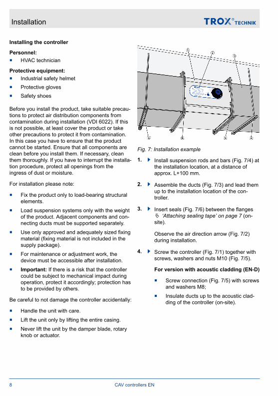
Fig. 7: Installation example
1. Install suspension rods and bars (Fig. 7/4) atthe installation location, at a distance ofapprox. L+100 mm.
2. Assemble the ducts (Fig. 7/3) and lead themup to the installation location of the con-troller.
3. Insert seals (Fig. 7/6) between the flangesÄ ‘Attaching sealing tape’ on page 7 (on-site).
Observe the air direction arrow (Fig. 7/2)during installation.
4. Screw the controller (Fig. 7/1) together withscrews, washers and nuts M10 (Fig. 7/5).
For version with acoustic cladding (EN-D)
Screw connection (Fig. 7/5) with screwsand washers M8;
Insulate ducts up to the acoustic clad-ding of the controller (on-site).
Installation
CAV controllers EN8

Wiring
DANGER!
Danger of electric shock! Do not touch any livecomponents! Electrical equipment carries a dan-gerous electrical voltage.
– Only skilled qualified electricians are allowedto work on the electrical system.
– Switch off the power supply before workingon any electrical equipment.
Installation instructions
For installation, the supply voltage and, if neces-sary, signal lines, must be connected for electricalactuators.
The connection is made according to the informa-tion given on the actuators or connection diagramsin this manual. These must be observed for project-specific wiring diagrams. The voltage ranges andthe terminal connections specified on the actuatorsmust be observed!
Personnel: Skilled qualified electrician
Please note during installation:
Legal and official regulations, in particular VDEguidelines.
Consideration of the technical connection rules(TCR) of the local network operators.
Wiring work for supply voltage and signal lineson site.
The rating and manufacture of customer-sideconnections and wiring must be carried out inaccordance with the recognised rules of elec-trical engineering.
Observe wiring guidelines and project-specificcircuit diagrams of the actuators.
The electrical connection to the actuator mayonly be made if the installation has been car-ried out correctly.
The 24 V supply voltage may only be suppliedwith a safety transformer.
If several actuators are connected to a 24 Vmains supply, it must be ensured that acommon zero or ground line is defined and notinterchanged.
The actuator contains no parts that can bereplaced or repaired by the user and may onlybe opened by the manufacturer.
Lay connecting cables in such a way that theycannot be accidentally damaged by mechan-ical impact or by heat.
Terminals for 0.5 – 2.5 mm², cables, rigid andflexible, AWG 22–10
Strain relief
Devices that are permanently installed in buildingsare stationary electrical equipment for which nostrain relief on the connecting cables is prescribed.
Connection diagram Vmin / Vmax switchingE01, E02
Fig. 8: Connection diagrams actuator E01, E02
1 1-wire control2 3-point control
S1 S2 Function
– Pos. 0 Actuator has stopped (undefined posi-tion)
open Pos. 2 Vmin
Closed Pos. 3 Vmax
Wiring
CAV controllers EN 9

Colour assignment of the connecting cablesE01, E02
Pos. Colour Connection AC DC
1 BU Supply N GND
2 BN Supply L +
3 BK Switch input L +
Connection diagram variable volume flow E03
Fig. 9: Constant control input signal E03
1 Room temperature controller2 Actual value output (value to be set)
Colour assignment of the connecting cablesE03
Pos. Colour Connection AC DC
1 BU Supply N GND
2 BN Supply L +
3 BK Signal w
4 GY Signal U
Room temperature control Fig. 9
A suitable room temperature controller or a DDCoutstation with 0-10 VDC output 2-wire (terminals 1and 3) connected. With a common supply voltage of24 V, note that terminal 1 is also ground for the con-trol signal.
Override control: With 24 VDC at terminal 3, thevolume flow rate set at the Vmax potentiometer isstarted.
Initial commissioning
Before you start commissioning:
Ensure that the device or unit has been cor-rectly fixed and connected to the ducting.
Ensure that the devices or units as well as theventilation system are clean and that there areno residual matter and foreign objects.
Important: If there is a risk that the controllercould be subject to mechanical impact duringoperation, protect it accordingly; protection hasto be provided by others.
For commissioning see also VDI 6022, part 1 – 'Hy-giene requirements for ventilation and air-condi-tioning systems and units'.
Volume flow rate setting ranges
Nominal size [l/s] (m³/h)
min max min max
200 × 100 39 164 140 590
300 × 100 65 260 234 936
300 × 150 82 460 295 1656
300 × 200 120 515 432 1854
400 × 200 200 875 720 3150
500 × 200 180 900 648 3240
600 × 200 225 1010 810 3636
400 × 250 200 885 720 3186
500 × 250 235 1190 846 4284
600 × 250 300 1310 1080 4716
400 × 300 310 1280 1116 4608
500 × 300 365 1580 1314 5688
600 × 300 350 1750 1260 6300
400 × 400 400 1750 1440 6300
500 × 400 360 1800 1296 6480
600 × 400 450 2020 1620 7272
500 × 500 470 2380 1692 8568
600 × 500 600 2620 2160 9432
600 × 600 700 3500 2520 12600
Initial commissioning
CAV controllers EN10

Setting the volume flow rate
Sufficient duct pressure must be ensured for alloperating conditions and for all control units. Themeasurement points for fan speed control must beselected accordingly.
Fig. 10: Setting the volume flow rate
1. Using the volume flow rate scale (Fig. 10/1),determine the setting value (1-10) for thedesired volume flow rate (l/s, m³/h, or cfm).
2. Loosen the hexagon socket screw(Fig. 10/3).
3. Set the rotary knob to the determined valueof the setting scale (Fig. 10/2) and fix it withthe hexagon socket screw (Fig. 10/3).
No further measurement or adjustment isnecessary.
Setting Vmin/Vmax actuators
Fig. 11: Setting the volume flow rate
Factory setting:
Vmin: 4
Vmax: 8
1. Using the volume flow rate scale (Fig. 11/1),determine the setting value (1-10) for thedesired volume flow rate (l/s, m³/h, or cfm).
2. Set the desired value at the Vmin potentiom-eter (Fig. 11/3).
3. Set the desired value at the Vmax potenti-ometer (Fig. 11/2).
4. Carry out a functional test using the testpush button and check the scale positionreached for the preset volume flow after themotorised adjustment process.
Initial commissioning
CAV controllers EN 11

Example for actuator E01, E02:
Given data:
EN 300x200– Vmin 432 m³/h– Vmax 1854 m³/h
Volume flow rate night-time operation 800m³/h
Volume flow rate day-time operation 1600m³/h
Settings according to scale Fig. 11:
Vmin potentiometer: 4.5
Vmax potentiometer: 9
Characteristics E03
Fig. 12: Characteristics of the control signal
1 Scale setting2 Setpoint value wVmin: 0 V ð scale setting 4.5Vmax: 10 V ð scale setting 9
Fig. 13: Characteristic actual value signal
1 Scale setting2 Actual value UVmin: 4.5 VVmax: 9 V
Actual value signal
The actual value signal of actuator variant E03corresponds to the current actuator position inthe scale range and is not a measure of theactual volume flow rate, since the CAV controllerdoes not measure the volume flow rate but onlycontrols it using the aerodynamic forces.
Initial commissioning
CAV controllers EN12

Maintenance and cleaning
Maintenance
It is the system owner's duty to set up a mainte-nance schedule, taking the actual operating condi-tions (contamination, operating time etc.) of theventilation system into consideration.
Important: Do not lubricate the bearings of thedamper blade.
Maintenance jobs to be carried out regularly:
Visually check the controller for contamination,damage and corrosion. Remove contamina-tion; if the controller has been damaged, or ifthere is any corrosion, replace the controller.
Check the fixing of the controller and of theconnected ductwork.
Replacement parts and retrofit
Incorrect replacement parts
WARNING!
Risk of injury from the use of incorrectreplacement parts!Incorrect or faulty replacement parts pose a riskto health and safety, and their use can causemalfunction, damage to property and total failureof equipment.
– Use only original replacement parts fromTROX.
Retrofit of electric actuator
The EN controller can easily be retrofitted with anelectric actuator.
Order code for retrofit kits:
NR-VAV-EN-E01 24 V AC / DC actuator min / maxswitching
NR-VAV-EN-E02 230 V AC / DC actuator min / maxswitching
NR-VAV-EN-E03 24 V AC / DC constant actuator forvariable operation
Cleaning
Please note:
The cleaning intervals given in the VDI 6022standard apply.
Clean surfaces with a damp cloth. Use only common household cleaners, do not
use any aggressive cleaning agents. Do not use cleaning agents that contain
chlorine.
Maintenance and cleaning
CAV controllers EN 13

CAV controllers EN14