cav 8 digital tv 2012 web.ppt - instituto de...
TRANSCRIPT

Audiovisual Communications, Fernando Pereira, 2012
DIGITAL TELEVISIONDIGITAL TELEVISION
Fernando Pereira
Instituto Superior Técnico
Audiovisual Communications, Fernando Pereira, 2012
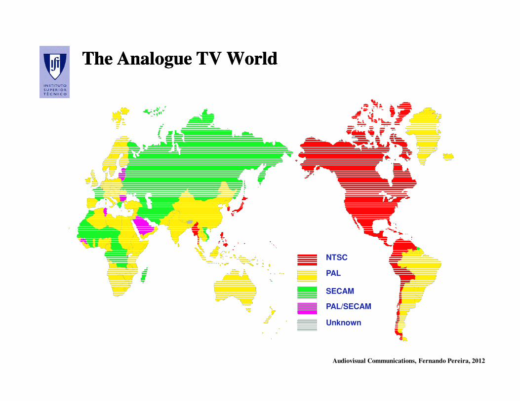
The Analogue TV WorldThe Analogue TV WorldThe Analogue TV WorldThe Analogue TV World
NTSC
PAL
SECAM
PAL/SECAM
Unknown
Audiovisual Communications, Fernando Pereira, 2012
TV Digital: What is it Really ?TV Digital: What is it Really ?TV Digital: What is it Really ?TV Digital: What is it Really ?
All the information – video, audio, data - arrives to our houses as a
discrete sequence of (pre-defined) symbols which together allow to
resynthesize the original information with a minimum acceptable
quality !
Audiovisual Communications, Fernando Pereira, 2012
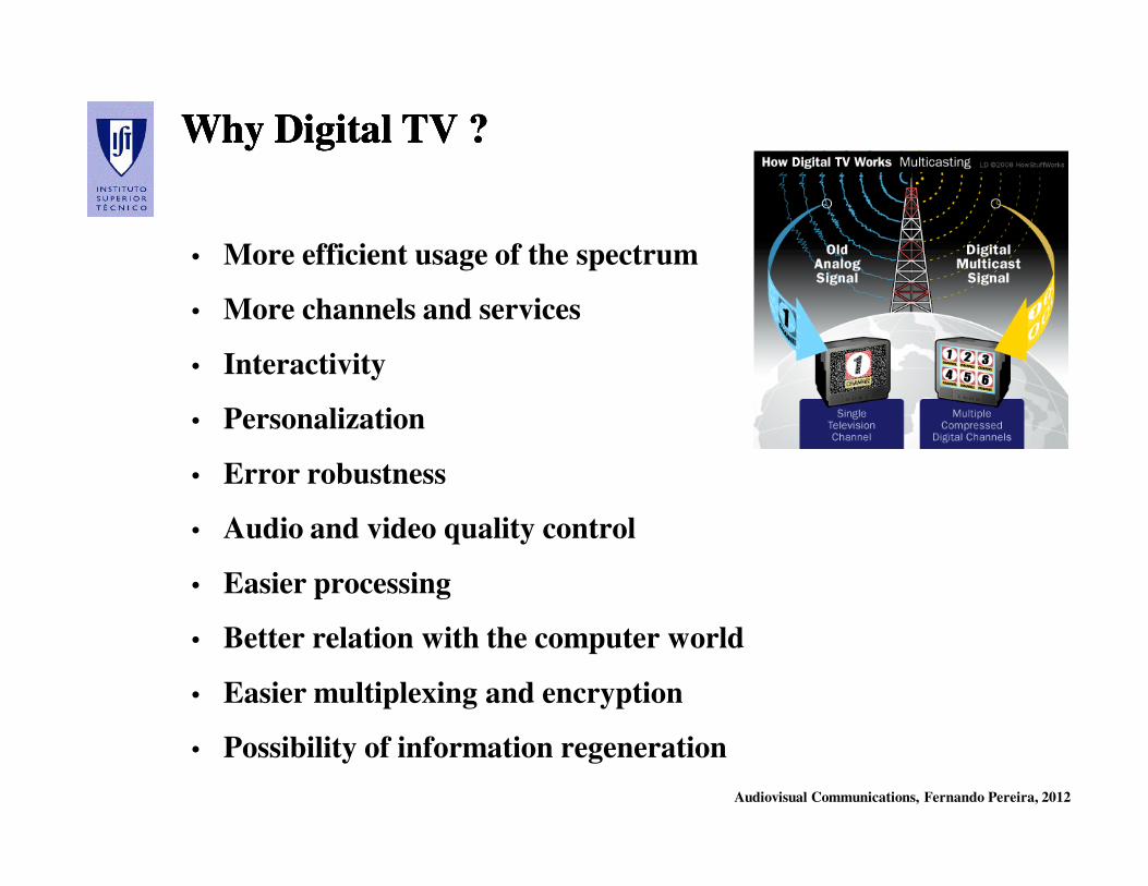
Why Digital TV ?Why Digital TV ?Why Digital TV ?Why Digital TV ?
• More efficient usage of the spectrum
• More channels and services
• Interactivity
• Personalization
• Error robustness
• Audio and video quality control
• Easier processing
• Better relation with the computer world
• Easier multiplexing and encryption
• Possibility of information regeneration
Audiovisual Communications, Fernando Pereira, 2012
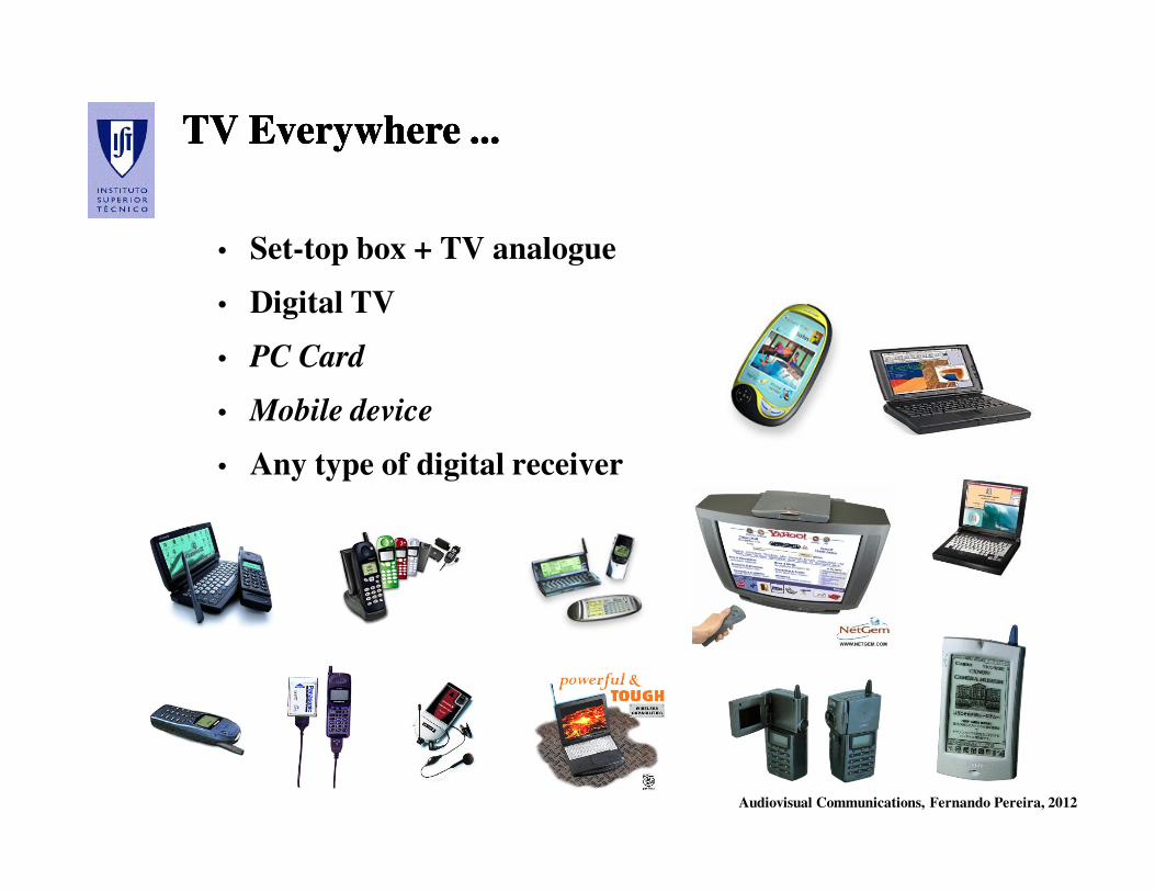
TV Everywhere ... TV Everywhere ... TV Everywhere ... TV Everywhere ...
• Set-top box + TV analogue
• Digital TV
• PC Card
• Mobile device
• Any type of digital receiver

Audiovisual Communications, Fernando Pereira, 2012
The Digital Domestic ScenarioThe Digital Domestic ScenarioThe Digital Domestic ScenarioThe Digital Domestic Scenario
DVD VCR
PCTelevision
Int.Rec.Dec.
SatelliteCable
Terrestrial ADSL...
Audiovisual Communications, Fernando Pereira, 2012
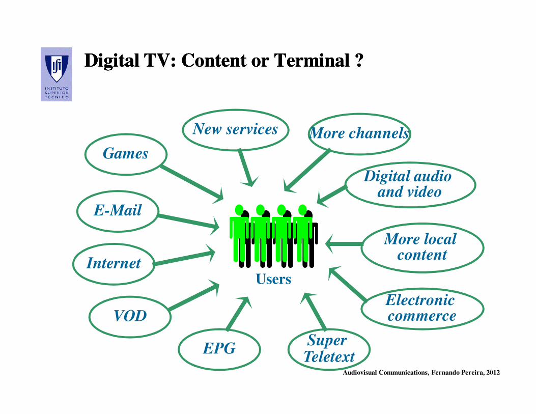
Digital TV: Content or Terminal ? Digital TV: Content or Terminal ? Digital TV: Content or Terminal ? Digital TV: Content or Terminal ?
Users
Games
Internet
VOD
EPGSuper Teletext
Electronic commerce
More local content
Digital audio and video
More channelsNew services

Audiovisual Communications, Fernando Pereira, 2012
Which Arguments Convince the Users ?Which Arguments Convince the Users ?Which Arguments Convince the Users ?Which Arguments Convince the Users ?
• Satisfaction of important needs / added value / functionalities
• Interoperability at the application level – users don’t care
much about the specific technical solution
• Quality and reliability
• Facility of usage
• Low cost of usage and equipment
• Variety and quality of content
• Interactivity
Audiovisual Communications, Fernando Pereira, 2012
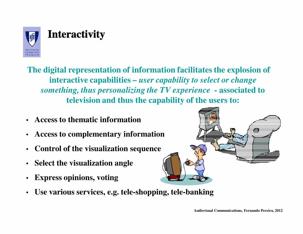
InteractivityInteractivityInteractivityInteractivity
The digital representation of information facilitates the explosion of
interactive capabilities – user capability to select or change
something, thus personalizing the TV experience - associated to
television and thus the capability of the users to:
• Access to thematic information
• Access to complementary information
• Control of the visualization sequence
• Select the visualization angle
• Express opinions, voting
• Use various services, e.g. tele-shopping, tele-banking
Audiovisual Communications, Fernando Pereira, 2012
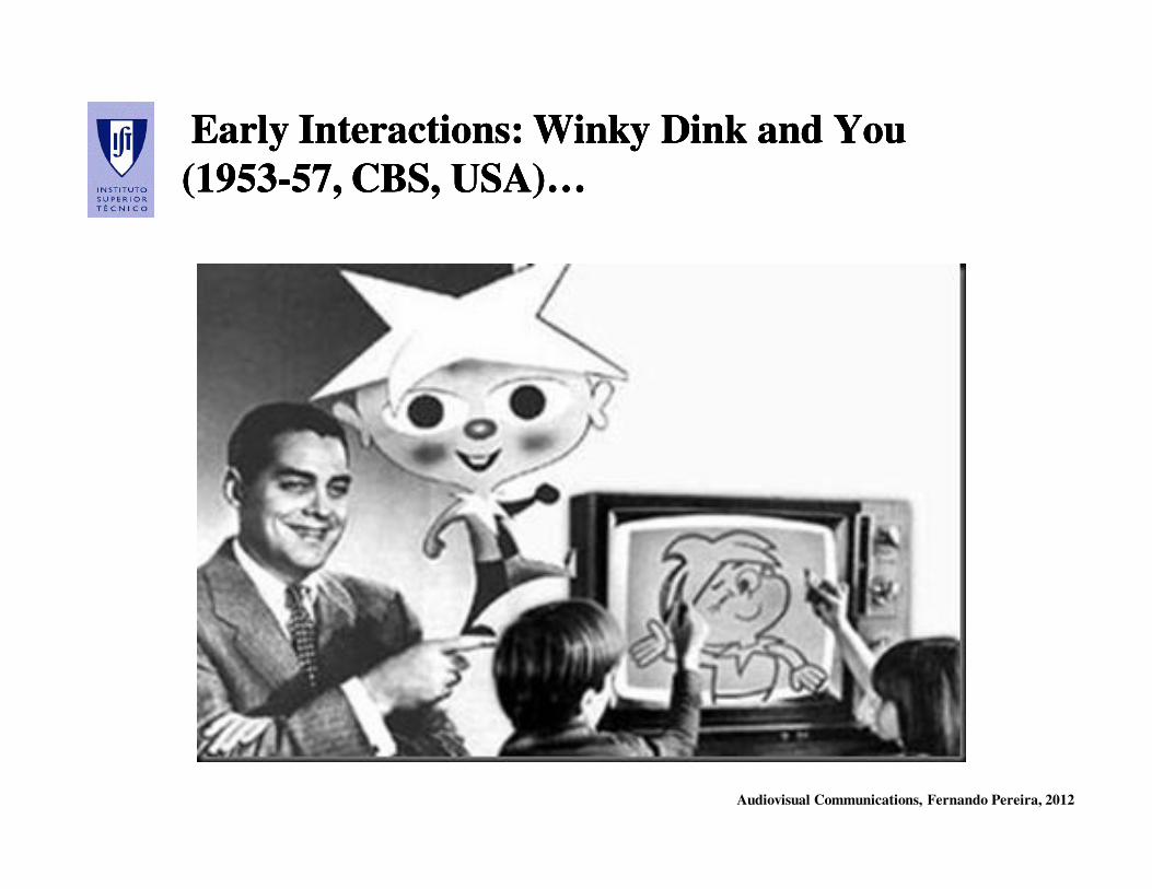
Early Interactions: Early Interactions: WinkyWinky Dink and You Dink and You
(1953(1953--57, CBS, USA)…57, CBS, USA)…
Early Interactions: Early Interactions: WinkyWinky Dink and You Dink and You
(1953(1953--57, CBS, USA)…57, CBS, USA)…

Audiovisual Communications, Fernando Pereira, 2012
Types of InteractivityTypes of InteractivityTypes of InteractivityTypes of Interactivity
• Low Interactivity – Zapping,
audio control
• Medium Interactivity – Defines
the program but does not change
it, e.g.VOD, teletext
• High Interactivity – Changes the
program, e.g. program
personalization, definition of end,
mix with Internet
Moreover, interactivity does not always require to use a feedback channel …

Audiovisual Communications, Fernando Pereira, 2012
BroadcastBroadcast MonocastMonocast
PassivityPassivity InteractivityInteractivity
Fixed schedulesFixed schedules Programs on Programs on demand, boxesdemand, boxes
AnalogueAnalogue DigitalDigital
Monthly Monthly subscriptionsubscription Pay per viewPay per view
TeletextTeletext World Wide WebWorld Wide Web
ZappersZappers EPGs, EPGs, personalizationpersonalization
Television: How is it Changing ?Television: How is it Changing ?Television: How is it Changing ?Television: How is it Changing ?
Audiovisual Communications, Fernando Pereira, 2012
Digital TVDigital TV
TechnologiesTechnologies
Audiovisual Communications, Fernando Pereira, 2012
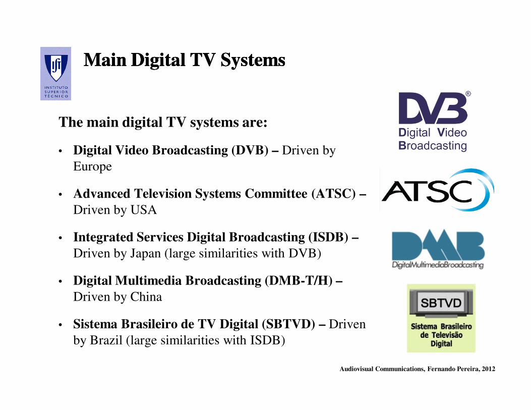
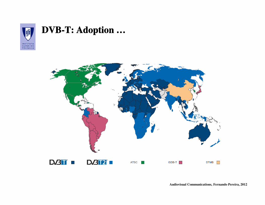
Main Digital TV SystemsMain Digital TV SystemsMain Digital TV SystemsMain Digital TV Systems
The main digital TV systems are:
• Digital Video Broadcasting (DVB) – Driven by
Europe
• Advanced Television Systems Committee (ATSC) –
Driven by USA
• Integrated Services Digital Broadcasting (ISDB) –
Driven by Japan (large similarities with DVB)
• Digital Multimedia Broadcasting (DMB-T/H) –
Driven by China
• Sistema Brasileiro de TV Digital (SBTVD) – Driven
by Brazil (large similarities with ISDB)
Audiovisual Communications, Fernando Pereira, 2012
What is DVB ?What is DVB ?What is DVB ?What is DVB ?
• Consortium with 220 members from 30 countries (at the
beginning mainly European), formed in September 1993:
- Content producers
- Equipment manufacturers
- Telecom operators
- Regulation organizations
with the objective to define standards for digital television
broadcasting over several transmission channels.
• Joint Technical Committee of ETSI / CENELEC / EBU
Audiovisual Communications, Fernando Pereira, 2012
DVB: Initial ObjectivesDVB: Initial ObjectivesDVB: Initial ObjectivesDVB: Initial Objectives
• High quality digital video delivery (up to HDTV)
• Delivery with good quality of TV programs using narrow
bandwidth channels and increase the number of programs in
current channels
• Reception in pocket terminals equipped with small reception
antennas (portable reception)
• Mobile reception with good quality of TV programs
• Possibility of easy transmission over various telecom networks
and integration with the PC world
Audiovisual Communications, Fernando Pereira, 2012
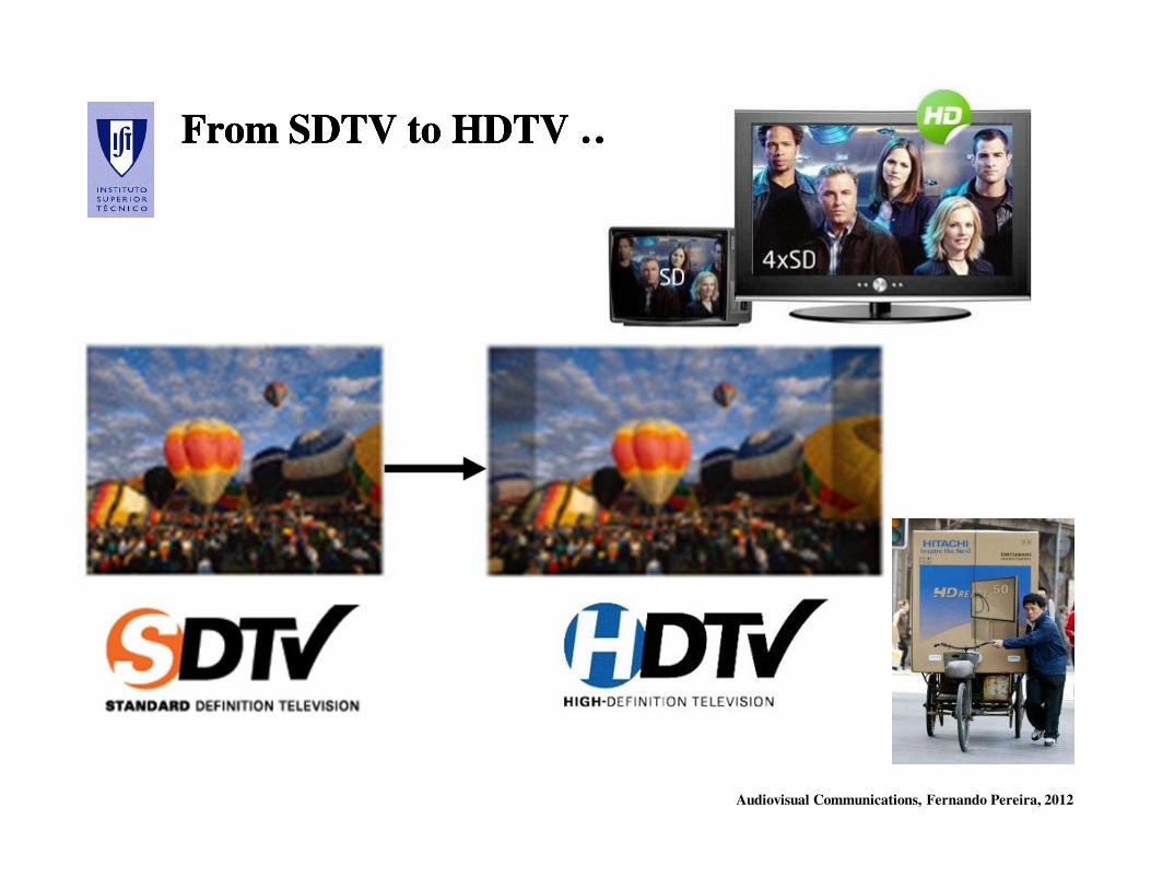
From SDTV to HDTV …From SDTV to HDTV …From SDTV to HDTV …From SDTV to HDTV …

Audiovisual Communications, Fernando Pereira, 2012
The New DVB Vision: Combining Worlds …The New DVB Vision: Combining Worlds …The New DVB Vision: Combining Worlds …The New DVB Vision: Combining Worlds …
DVB’s vision is to build a content environment
that combines the stability and
interoperability of the world of broadcast with
the vigor, innovation, and multiplicity of
services of the world of the Internet.”
DVB, 2000

Audiovisual Communications, Fernando Pereira, 2012
The DVB Scenarios and StandardsThe DVB Scenarios and StandardsThe DVB Scenarios and StandardsThe DVB Scenarios and Standards
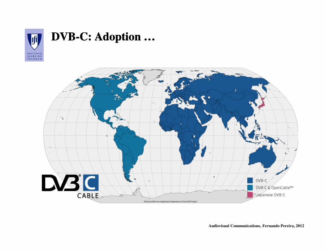
• Cable: DVB-C (1994), DVB-C2 (2008)
• Satellite: DVB-S (1997), DVB-S2 (2005)
• Terrestrial: DVB-T (1997), DVB-T2 (2008)
• DVB-MHP (Multimedia Home Platform,
2000) – middleware tools allowing to use a
single set-top box for all services and
applications (hardware abstraction)
• Portable: DVB-H (2004)
• ...
Audiovisual Communications, Fernando Pereira, 2012
DVBDVB--C: Adoption …C: Adoption …DVBDVB--C: Adoption …C: Adoption …
Audiovisual Communications, Fernando Pereira, 2012
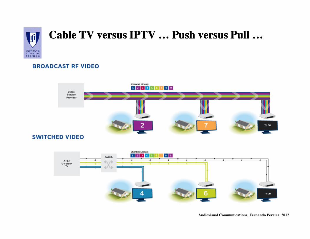
Cable TV versus IPTV … Push versus Pull …Cable TV versus IPTV … Push versus Pull …Cable TV versus IPTV … Push versus Pull …Cable TV versus IPTV … Push versus Pull …

Audiovisual Communications, Fernando Pereira, 2012
DVBDVB--S: Adoption …S: Adoption …DVBDVB--S: Adoption …S: Adoption …
Audiovisual Communications, Fernando Pereira, 2012
DVBDVB--T: Adoption …T: Adoption …DVBDVB--T: Adoption …T: Adoption …
Audiovisual Communications, Fernando Pereira, 2012
DVB TechnologiesDVB Technologies

Audiovisual Communications, Fernando Pereira, 2012
The DVB SpecificationsThe DVB SpecificationsThe DVB SpecificationsThe DVB Specifications
The DVB specifications – also ETSI standards – define all the modules
in the television delivery chain which need a normative specification;
this is made both by using available standards defined by other
standardization bodies and developing new (DVB) specifications.
The main modules specified are:
• Audio and Video Source Coding - MPEG-2 Audio and MPEG-2 Video
are adopted; later also H.264/AVC has been adopted
• Synchronization and Multiplexing - MPEG-2 Systems is adopted
• Channel Coding
• Modulation
• Conditional Access
Audiovisual Communications, Fernando Pereira, 2012
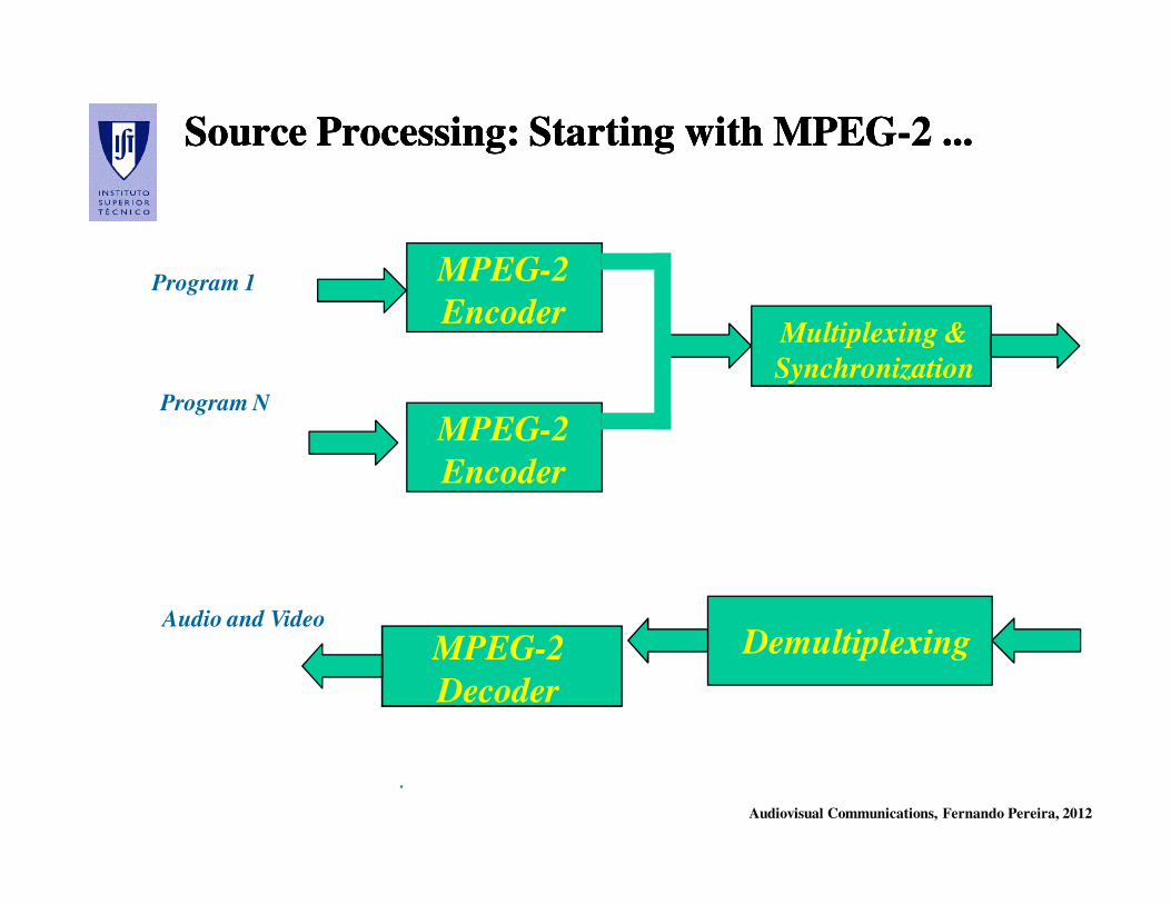
Source Processing: Starting with MPEGSource Processing: Starting with MPEG--2 ...2 ...Source Processing: Starting with MPEGSource Processing: Starting with MPEG--2 ...2 ...
MPEG-2
Encoder
MPEG-2
Encoder
Multiplexing &
Synchronization
MPEG-2
Decoder
Demultiplexing
Program 1
Program N
Audio and Video
.
Audiovisual Communications, Fernando Pereira, 2012
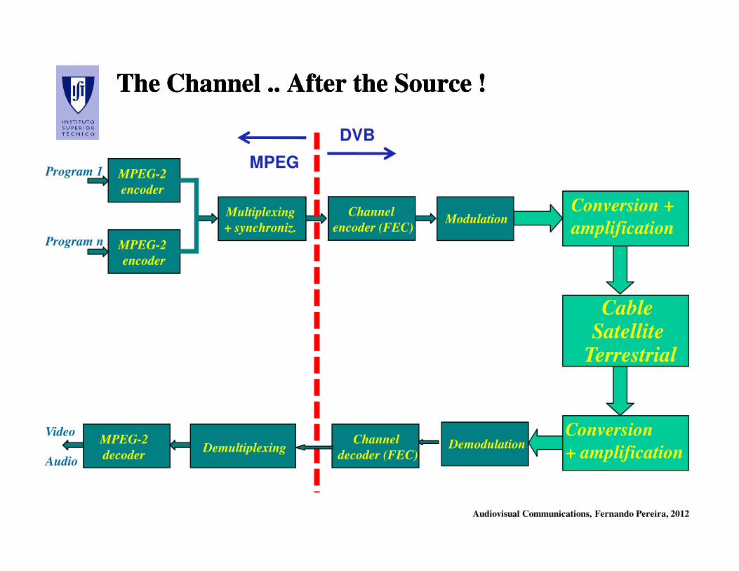
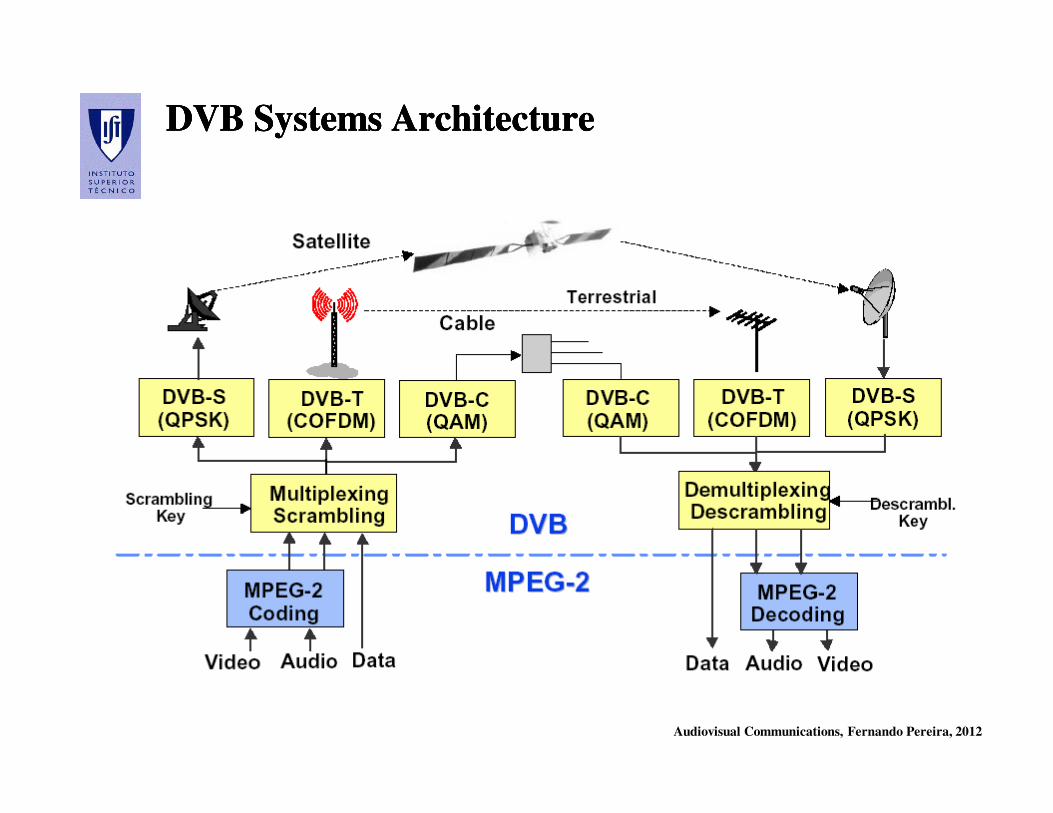
The Channel .. After the Source !The Channel .. After the Source !The Channel .. After the Source !The Channel .. After the Source !
Conversion
+ amplification
CableSatellite
Terrestrial
Conversion +
amplification
Video
Audio
Program 1
Program n
MPEG-2
encoder
MPEG-2
encoder
Multiplexing
+ synchroniz.
MPEG-2
decoderDemultiplexing
Modulation
Demodulation
Channel
encoder (FEC)
Channel
decoder (FEC)
MPEG
DVB
Audiovisual Communications, Fernando Pereira, 2012
MPEGMPEG--2 Standard2 Standard

Audiovisual Communications, Fernando Pereira, 2012
MPEGMPEG--2: Objectivos2: ObjectivosMPEGMPEG--2: Objectivos2: Objectivos
Generic Coding of Moving Pictures and Associated Audio
Audio and video coding for high quality transmission and storage,
e.g. high and medium definition television.
• The ISO/IEC MPEG-2 Video standard is a joint development with
ITU-T where it is designated as Recommendation H.262.
• The MPEG-2 standard should have covered audiovisual coding up
to 10 Mbit/s, leaving to MPEG-3 the higher rates and definitions.
However, since the MPEG-2 standard addressed well the HDTV
space, MPEG-3 was never defined and MPEG-2 lost its upper
bitrate limit.
Audiovisual Communications, Fernando Pereira, 2012
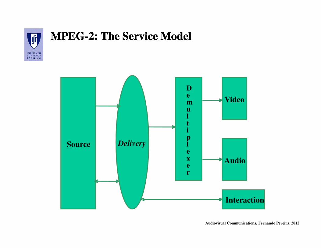
MPEGMPEG--2: The Service Model2: The Service ModelMPEGMPEG--2: The Service Model2: The Service Model
Source Delivery
Video
Audio
Interaction
Demul t iplexer
Audiovisual Communications, Fernando Pereira, 2012
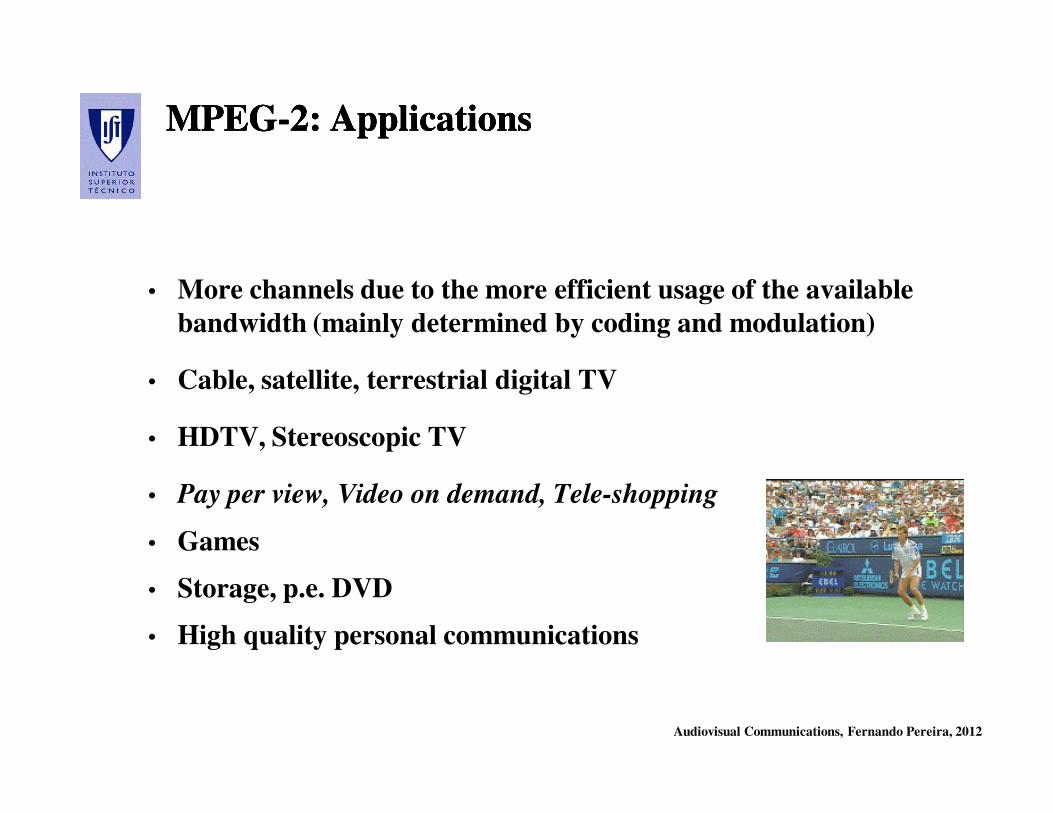
MPEGMPEG--2: Applications2: ApplicationsMPEGMPEG--2: Applications2: Applications
• More channels due to the more efficient usage of the available
bandwidth (mainly determined by coding and modulation)
• Cable, satellite, terrestrial digital TV
• HDTV, Stereoscopic TV
• Pay per view, Video on demand, Tele-shopping
• Games
• Storage, p.e. DVD
• High quality personal communications
Audiovisual Communications, Fernando Pereira, 2012
MPEGMPEG--2: Which Advantages ?2: Which Advantages ?MPEGMPEG--2: Which Advantages ?2: Which Advantages ?
• Offers more channels, e.g. thematic channels, regional channels
• Offers various angles of visualization, e.g. in the transmission of
music or sports
• Introduction of high definition television
• Introduction of stereoscopic television
• Offers a large variety of television related services, e.g. VOD
• Releases bandwidth allocated to terrestrial TV, notably for the
expansion of mobile networks
Audiovisual Communications, Fernando Pereira, 2012
MPEGMPEG--2 Standard: Organization 2 Standard: Organization MPEGMPEG--2 Standard: Organization 2 Standard: Organization
•• Part 1 Part 1 -- SYSTEMSSYSTEMS – Specified the multiplexing, synchronization and
protection of coded elementary bitstreams (audio, video and data).
•• Part 2 Part 2 -- VIDEOVIDEO – Specifies the coded representation of video signals.
•• Part 3 Part 3 -- AUDIOAUDIO - Specifies the coded representation of audio signals.
•• Part 4 Part 4 –– CONFORMANCE TESTINGCONFORMANCE TESTING – Specifies compliance tests for
decoders and streams.
•• Part 5 Part 5 –– REFERENCE SOFTWAREREFERENCE SOFTWARE – Includes software implementing
the technical specification parts.
•• Part 6 Part 6 -- DSMDSM--CC (Digital Storage Media CC (Digital Storage Media –– Command Control)Command Control) -
Specifies user management and control protocols; they constitute and
extension of the Systems parts.

Audiovisual Communications, Fernando Pereira, 2012
MPEGMPEG--2 Standard2 Standard
Part 1: Systems Part 1: Systems
Audiovisual Communications, Fernando Pereira, 2012
MPEGMPEG--2 Systems: Objective2 Systems: ObjectiveMPEGMPEG--2 Systems: Objective2 Systems: Objective
MPEGMPEG--2 Systems has the basic objective to combine and 2 Systems has the basic objective to combine and
synchronize one or more coded audio and video synchronize one or more coded audio and video bitstreamsbitstreams
in a single multiplexed in a single multiplexed bitstreambitstream. .
The main objectives of this standards regard:
• Multiplexing of various streams, e.g. audio and video from one
program or several programs together
• Synchronization between streams, e.g. audio and video from one
program or several programs
Audiovisual Communications, Fernando Pereira, 2012
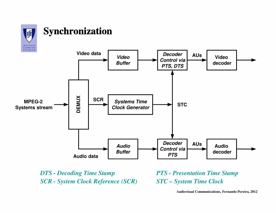
SynchronizationSynchronizationSynchronizationSynchronization
DTS - Decoding Time Stamp PTS - Presentation Time Stamp
SCR - System Clock Reference (SCR) STC – System Time Clock
DecoderControl via
PTS
Decoder
Control via
PTS, DTS
AUs
STCMPEG-2
Systems stream
DE
MU
X
Video
Buffer
Audio
Buffer
Systems Time
Clock Generator
Video
decoder
Audio
decoder
SCR
AUs
Video data
Audio data
Audiovisual Communications, Fernando Pereira, 2012
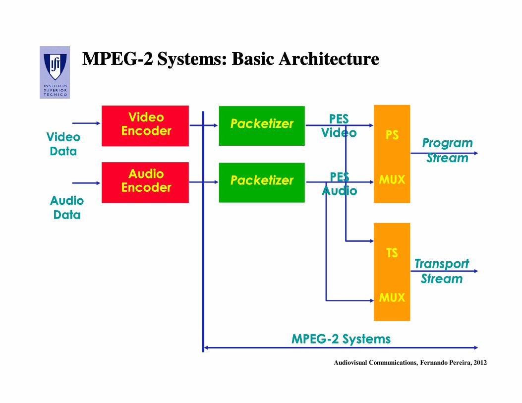
MPEGMPEG--2 Systems: Basic Architecture2 Systems: Basic ArchitectureMPEGMPEG--2 Systems: Basic Architecture2 Systems: Basic Architecture
Video Video EncoderEncoder
PacketizerPacketizer
Audio Audio EncoderEncoder
PacketizerPacketizer
PES PES VideoVideo PSPS
MUXMUX
TSTS
MUXMUX
ProgramProgram
StreamStream
TransportTransport
StreamStream
PES PES AudioAudio
MPEGMPEG--2 Systems2 Systems
Video Video
DataData
Audio Audio
DataData
Audiovisual Communications, Fernando Pereira, 2012
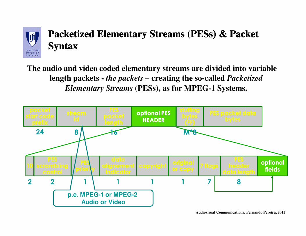
Packetized Elementary Streams (PESs) & Packet Packetized Elementary Streams (PESs) & Packet
SyntaxSyntax
Packetized Elementary Streams (PESs) & Packet Packetized Elementary Streams (PESs) & Packet
SyntaxSyntax
The audio and video coded elementary streams are divided into variable
length packets - the packets – creating the so-called Packetized
Elementary Streams (PESs), as for MPEG-1 Systems.
packet packet start codestart codeprefixprefix
streamstreamidid
stuffingstuffingbytesbytes(FF)(FF)
PESPESpacket packet lengthlength
optional PESoptional PESHEADERHEADER
PES packet data PES packet data bytesbytes
1010PESPES
scramblingscramblingcontrolcontrol
24 8 16 M*8
2
PESPESprioritypriority
data data alignementalignementindicatorindicator
copyrightcopyrightoriginal original or copyor copy
7 flags7 flagsPESPES
headerheaderdata lengthdata length
optional optional fieldsfields
2 1 1 1 1 7 8
p.e. MPEG-1 or MPEG-2 Audio or Video
Audiovisual Communications, Fernando Pereira, 2012
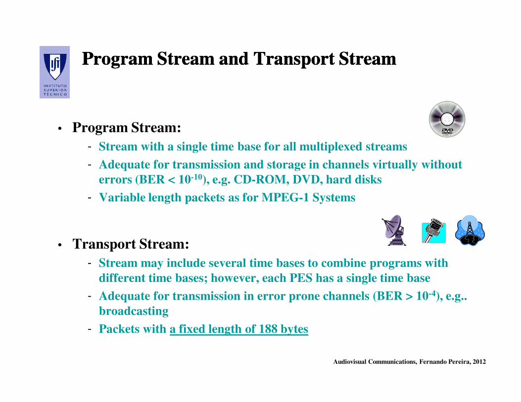
Program Stream and Transport Stream Program Stream and Transport Stream Program Stream and Transport Stream Program Stream and Transport Stream
• Program Stream:
- Stream with a single time base for all multiplexed streams
- Adequate for transmission and storage in channels virtually without
errors (BER < 10-10), e.g. CD-ROM, DVD, hard disks
- Variable length packets as for MPEG-1 Systems
• Transport Stream:
- Stream may include several time bases to combine programs with
different time bases; however, each PES has a single time base
- Adequate for transmission in error prone channels (BER > 10-4), e.g..
broadcasting
- Packets with a fixed length of 188 bytes

Audiovisual Communications, Fernando Pereira, 2012
Decoding Program Streams …Decoding Program Streams …Decoding Program Streams …Decoding Program Streams …
MediumMediumspecificspecificdecoderdecoder
ProgramStreamdecoder
DSMDSMClockcontrol
Video decoder
Decoded Decoded
videovideo
Decoded Decoded
audioaudioAudio decoder
MPEGMPEG--2 2 Program Program StreamStream
Audiovisual Communications, Fernando Pereira, 2012
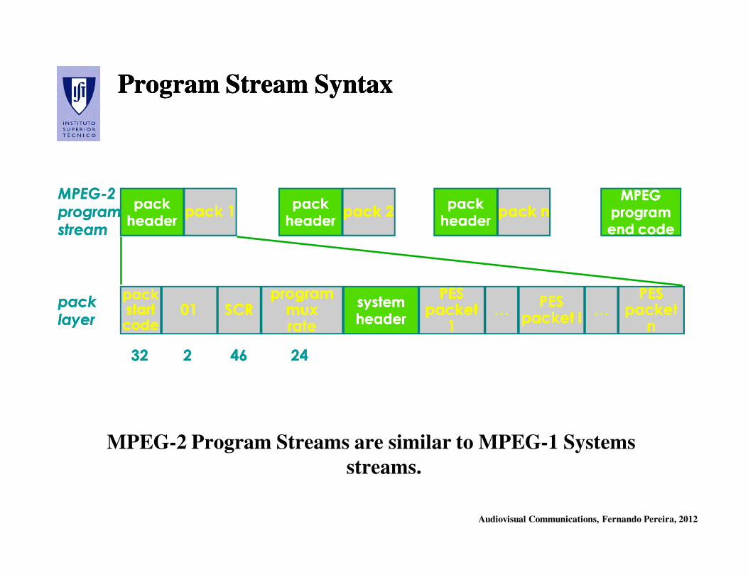
Program Stream SyntaxProgram Stream SyntaxProgram Stream SyntaxProgram Stream Syntax
packpackstartstartcodecode
0101systemsystemheaderheader
SCRSCRprogram program muxmuxraterate
PESPESpacket packet
11
packpackheaderheader
pack 1pack 1packpackheaderheader
pack 2pack 2packpackheaderheader
pack npack nMPEGMPEG
programprogramend codeend code
…PESPES
packet ipacket i…
PESPESpacket packet
nn
MPEGMPEG--22programprogramstreamstream
packpacklayerlayer
3232 22 4646 2424
MPEG-2 Program Streams are similar to MPEG-1 Systems
streams.
Audiovisual Communications, Fernando Pereira, 2012
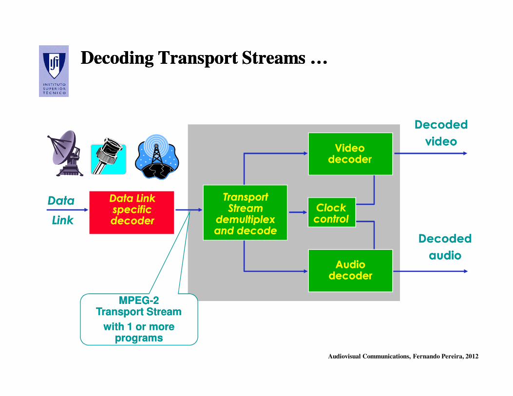
Decoding Transport Streams …Decoding Transport Streams …Decoding Transport Streams …Decoding Transport Streams …
Data LinkData Linkspecificspecificdecoderdecoder
TransportTransportStreamStream
demultiplexdemultiplexand decodeand decode
DataData
LinkLinkClockClockcontrolcontrol
Video Video decoderdecoder
Decoded Decoded
videovideo
Decoded Decoded
audioaudioAudio Audio decoderdecoder
MPEGMPEG--2 2 Transport StreamTransport Stream
with 1 or more with 1 or more programsprograms
Audiovisual Communications, Fernando Pereira, 2012
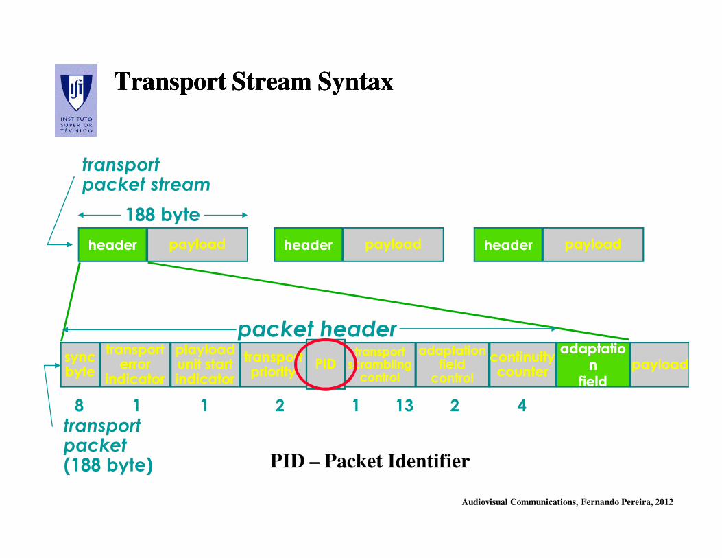
Transport Stream SyntaxTransport Stream SyntaxTransport Stream SyntaxTransport Stream Syntax
headerheader
packet header
payloadpayload headerheader payloadpayload headerheader payloadpayload
syncsyncbytebyte
transporttransporterror error
indicatorindicator
playloadplayloadunit startunit startindicatorindicator
transporttransportprioritypriority
PIDPIDtransporttransportscramblingscramblingcontrolcontrol
adaptationadaptationfieldfieldcontrolcontrol
continuitycontinuitycountercounter
adaptatioadaptationn
fieldfield
payloadpayload
transportpacket stream
188 byte
transportpacket(188 byte)
8 1 1 2 1 13 2 4
PID – Packet Identifier
Audiovisual Communications, Fernando Pereira, 2012
‘Surviving in the Labyrinth’ …‘Surviving in the Labyrinth’ …‘Surviving in the Labyrinth’ …‘Surviving in the Labyrinth’ …
In order a user may find
the elementary streams
he/she needs in a
MPEG-2 Transport
Stream, e.g. audio and
video for RTP 2 or SIC,
some auxiliary data is
needed !
Audiovisual Communications, Fernando Pereira, 2012
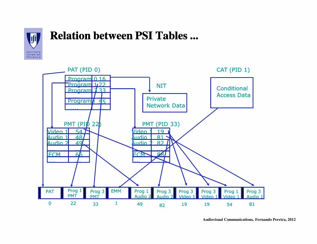
Program Specific Information (PSI) Program Specific Information (PSI) Program Specific Information (PSI) Program Specific Information (PSI)
Program Specific Information (PSI) is delivered in the transport stream
‘showing the path in the labyrinth’.
• PSI is carried using 4 tables (corresponding to a small bitrate budget)
• Each table is repeated many times (in a carroussel), e.g. 10-50/s, and
corresponds to a different PID
• Tables are only applicable to Transport Streams
• A common syntax is defined to segment and carry the tables in Transport
Packets
• The syntax allows a clean and backward compatible strategy to possibly
extend the current standard with new tables, both standardized or
privately (e.g. DVB) defined
Audiovisual Communications, Fernando Pereira, 2012
Transport Stream PSI TablesTransport Stream PSI TablesTransport Stream PSI TablesTransport Stream PSI Tables
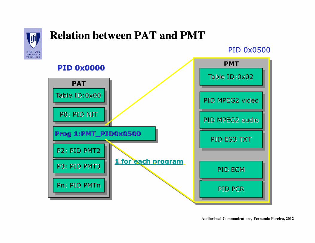
•• Program Association TableProgram Association Table (PAT(PAT)) – Corresponds to PID 0x00 and it is
mandatory; it contains the PIDs for the PMTs corresponding to each
program in each transport stream; it also contains the PID for the NIT.
•• Program Map TableProgram Map Table (PMT)(PMT) – Each PMT indicates the PIDs
corresponding to the elementary streams for each program; it is always
on the clear even if the programs are encrypted.
•• Conditional Access TableConditional Access Table (CAT)(CAT) – Corresponds to PID 0x01 and it
contains the PIDs for the packets with conditional access data, e.g.
corresponding to the DVB tables with the access keys for the encrypted
programs.
•• Network Information TableNetwork Information Table (NIT)(NIT) – Information about the network, e.g.
the frequency for each RF channel (only the syntax is defined in
MPEG-2).
Audiovisual Communications, Fernando Pereira, 2012
Program Association Table (PAT) Program Association Table (PAT) Program Association Table (PAT) Program Association Table (PAT)
• Mandatory table for each transport stream
• Delivered in the packets with PID = 0
• Indicates for all programs present in this transport stream, the
relation between the program number (0 - 65535) and the PID
of the packets transporting the map of that program, this means
the Program Map Table
• The PAT is always sent without protection even if all programs
in the transport stream are protected
Audiovisual Communications, Fernando Pereira, 2012
Program Map Table Program Map Table (PMT)(PMT)Program Map Table Program Map Table (PMT)(PMT)
• Provides detailed information about a specific program
• Identifies the packets (PIDs) transporting the audio and video
elementary streams associated to the program it refers
• Identifies the PID for the packets transporting the temporal
references associated to the relevant program clock (SCRs)
• May be enhanced with a set of descriptors (standard or user
specified), e.g.
- Video coding parameters
- Audio coding parameters
- Language identification
- Conditional access information
Audiovisual Communications, Fernando Pereira, 2012
Relation between PAT and PMTRelation between PAT and PMTRelation between PAT and PMTRelation between PAT and PMT
PATPAT
Table ID:0x00Table ID:0x00Table ID:0x00
P0: PID NITP0: PID NITP0: PID NIT
Prog 8001:PMT_PID0x0500ProgProg 1:PMT_PID0x05001:PMT_PID0x0500
P2: PID PMT2P2: PID PMT2P2: PID PMT2
P3: PID PMT3P3: PID PMT3P3: PID PMT3
Pn: PID PMTnPnPn: PID : PID PMTnPMTn
PID 0x0000PID 0x0000 PMTPMT
Table ID:0x02Table ID:0x02Table ID:0x02
PID MPEG2 videoPID MPEG2 videoPID MPEG2 video
PID PCRPID PCRPID PCR
PID MPEG2 audioPID MPEG2 audioPID MPEG2 audio
PID ES3 TXTPID ES3 TXTPID ES3 TXT
PID ECMPID ECMPID ECM
PID 0x0500PID 0x0500
1 1 for each program1 for each program
Audiovisual Communications, Fernando Pereira, 2012
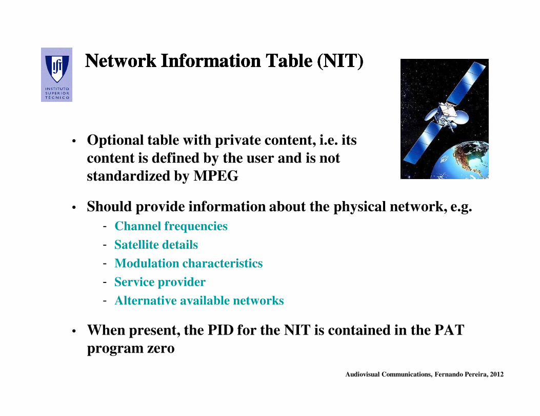
Network Information Table (NITNetwork Information Table (NIT))Network Information Table (NITNetwork Information Table (NIT))
• Optional table with private content, i.e. its
content is defined by the user and is not
standardized by MPEG
• Should provide information about the physical network, e.g.
- Channel frequencies
- Satellite details
- Modulation characteristics
- Service provider
- Alternative available networks
• When present, the PID for the NIT is contained in the PAT
program zero

Audiovisual Communications, Fernando Pereira, 2012
Conditional Access Table (CAT)Conditional Access Table (CAT)Conditional Access Table (CAT)Conditional Access Table (CAT)
• Mandatory whenever there is, at least, one elementary stream in
the transport stream which is protected
• Provides information about the used protection system
(scrambling)
• Identifies the PIDs for the packets transporting the conditional
access management and authorization information
• Its format is not specified by the MPEG-2 standard since it
depends on the used protection mechanism which is typically
operator dependent
Audiovisual Communications, Fernando Pereira, 2012
......
PMT (PID 33)PMT (PID 33)
191981818282......8888......
Video 1Video 1Audio 1Audio 1Audio 2Audio 2......ECMECM
NITNIT
PrivatePrivate
Network DataNetwork Data
CAT (PID 1)CAT (PID 1)
ConditionalConditional
Access DataAccess Data
EMMEMM
11
Prog 1Prog 1PMTPMT
2222
Prog 3Prog 3PMTPMT
3333 4949
ProgProg 11Audio 2Audio 2
5454
Prog 1Prog 1Video 1Video 1
545448484949......6666......
Video 1Video 1Audio 1Audio 1Audio 2Audio 2......ECMECM......
PMT (PID 22)PMT (PID 22)
PATPAT
00
PAT (PID 0)PAT (PID 0)
Program 0Program 0 1616Program 1Program 1 2222Program 3Program 3 3333…...…... ......Program iProgram i 5555…...…... ......
Relation between PSI Tables ...Relation between PSI Tables ...Relation between PSI Tables ...Relation between PSI Tables ...
8282
Prog 3Prog 3Audio 2Audio 2
1919
Prog 3Prog 3Video 1Video 1
1919
Prog 3Prog 3Video 1Video 1
8181
Prog 3Prog 3Audio 1Audio 1
Audiovisual Communications, Fernando Pereira, 2012
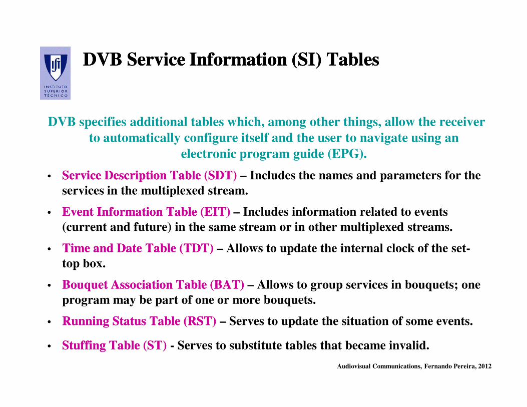
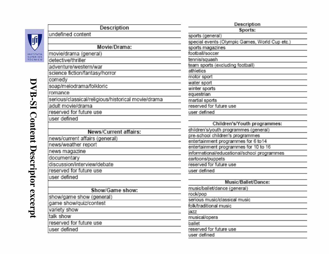
DVB Service Information (SI) TablesDVB Service Information (SI) TablesDVB Service Information (SI) TablesDVB Service Information (SI) Tables
DVB specifies additional tables which, among other things, allow the receiver
to automatically configure itself and the user to navigate using an
electronic program guide (EPG).
•• Service Description Table (SDT)Service Description Table (SDT) – Includes the names and parameters for the
services in the multiplexed stream.
•• Event Information Table (EIT)Event Information Table (EIT) – Includes information related to events
(current and future) in the same stream or in other multiplexed streams.
•• Time and Date Table (TDT)Time and Date Table (TDT) – Allows to update the internal clock of the set-
top box.
•• Bouquet Association Table (BAT)Bouquet Association Table (BAT) – Allows to group services in bouquets; one
program may be part of one or more bouquets.
•• Running Status Table (RST)Running Status Table (RST) – Serves to update the situation of some events.
•• Stuffing Table (ST)Stuffing Table (ST) - Serves to substitute tables that became invalid.
Audiovisual Communications, Fernando Pereira, 2012
ZapppingZappping or Filtering ?or Filtering ?ZapppingZappping or Filtering ?or Filtering ?

Audiovisual Communications, Fernando Pereira, 2012
EPG: EPG: ProgramProgram TimeliningTimeliningEPG: EPG: ProgramProgram TimeliningTimelining
Audiovisual Communications, Fernando Pereira, 2012
DV
B-S
I Co
nten
t Descrip
tor ex
cerpt
Audiovisual Communications, Fernando Pereira, 2012
MPEGMPEG--2 Standard2 Standard
Part 2: Video Part 2: Video
Audiovisual Communications, Fernando Pereira, 2012
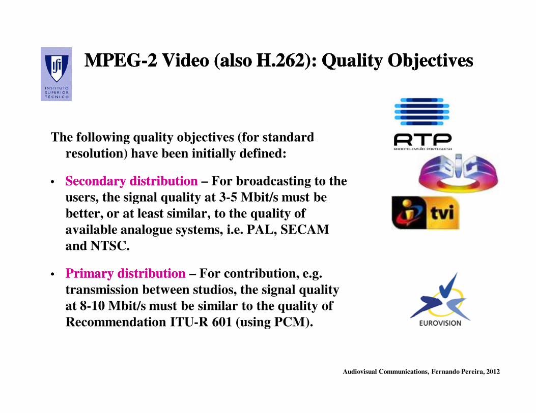
MPEGMPEG--2 Video (also H.262): Quality Objectives2 Video (also H.262): Quality ObjectivesMPEGMPEG--2 Video (also H.262): Quality Objectives2 Video (also H.262): Quality Objectives
The following quality objectives (for standard
resolution) have been initially defined:
•• Secondary distributionSecondary distribution – For broadcasting to the
users, the signal quality at 3-5 Mbit/s must be
better, or at least similar, to the quality of
available analogue systems, i.e. PAL, SECAM
and NTSC.
•• Primary distributionPrimary distribution – For contribution, e.g.
transmission between studios, the signal quality
at 8-10 Mbit/s must be similar to the quality of
Recommendation ITU-R 601 (using PCM).

Audiovisual Communications, Fernando Pereira, 2012
Better Encoders for the Same Decoders ...Better Encoders for the Same Decoders ...Better Encoders for the Same Decoders ...Better Encoders for the Same Decoders ...
MPEG-2 Video

Audiovisual Communications, Fernando Pereira, 2012
MPEGMPEG--2 Video: the Quality2 Video: the QualityMPEGMPEG--2 Video: the Quality2 Video: the Quality
The quality requirements depend on the application (thus type of
content) and are strongly related to
• Resolution (in space and time) of the video signal
• Bitrate available (and thus compression factor)
Other important requirements related to quality:
• Quality robustness of the coding scheme to sudden changes of the
signal statistics, e.g. scene changes
• Quality robustness to cascading this means successive coding and
decoding processes

Audiovisual Communications, Fernando Pereira, 2012
MPEGMPEG--2 Video: Requirements2 Video: RequirementsMPEGMPEG--2 Video: Requirements2 Video: Requirements
• Large range of spatial and temporal resolutions, both in
progressive and interlaced formats
• Several chrominance subsampling formats, e.g. 4:4:4, 4:2:2 and
4:2:0
• Flexibility in terms of bitrates, constant or variable
• Special modes, e.g. random access for edition and channel hoping,
fast modes, conditional access, and easy transcoding to MPEG-1
Video, H.261 and JPEG
• Flexibility in adapting to different transmission and storage
channels, e.g. in terms of synchronization and error resilience
Audiovisual Communications, Fernando Pereira, 2012
MPEGMPEG--2 Video: the Compatibility2 Video: the CompatibilityMPEGMPEG--2 Video: the Compatibility2 Video: the Compatibility
The compatibility among standards allows to offer some continuity regarding
the already available standards – JPEG, H.261, MPEG-1 Video –
providing some interoperability between the various applications.
Two main types of compatibility are relevant:
•• BackwardBackward compatibilitycompatibility – A MPEG-2 Video decoder is able to decode a
coded bitstream compliant with a previously available standard.
•• ForwardForward compatibilitycompatibility – A decoder compliant with a previously available
standard, e.g. MPEG-1 Video, is able to, totally or partially, decode in a
useful way a bitstream compliant with MPEG-2 Video.
MPEG-2 Video foresees some compatibility mechanisms with MPEG-1 Video
(intrinsic to the MPEG-2 Video syntax) and H.261 (using spatial
scalability).
Audiovisual Communications, Fernando Pereira, 2012
MPEGMPEG--2 2 VideoVideo: : thethe ComplexityComplexityMPEGMPEG--2 2 VideoVideo: : thethe ComplexityComplexity
The complexity assessment of the encoders and decoders is essential for the
adaptation to the technological constraints and adoption by the market.
•• AssymmetricAssymmetric ApplicationsApplications – For the ‘one encoder, many decoders’ type of
applications, it is possible to develop high quality encoders even if at the cost
of additional complexity since the overall system cost is mainly related to the
decoders which should have a reduced complexity (and cost).
•• SymmetricSymmetric ApplicationsApplications – For the ‘one to one’ type of applications, both the
encoders and decoder should have a reasonable (low) complexity.
The complexity of a codec is assessed based on parameters such as memory size
to contain the reference images, required access to memory speed, number of
operations per second, size of coding tables and number of coding table
accesses per second.
Audiovisual Communications, Fernando Pereira, 2012
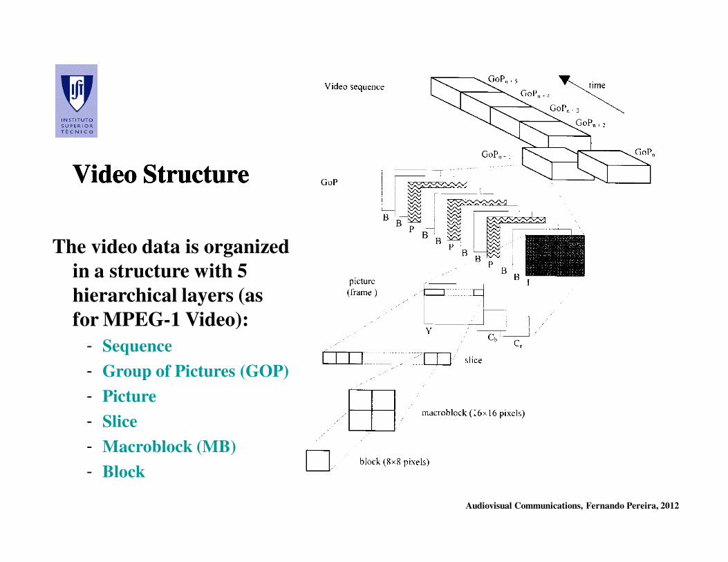
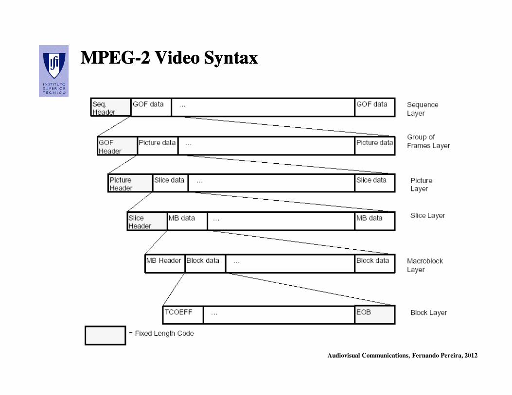
Video StructureVideo StructureVideo StructureVideo Structure
The video data is organized
in a structure with 5
hierarchical layers (as
for MPEG-1 Video):
- Sequence
- Group of Pictures (GOP)
- Picture
- Slice
- Macroblock (MB)
- Block
Audiovisual Communications, Fernando Pereira, 2012
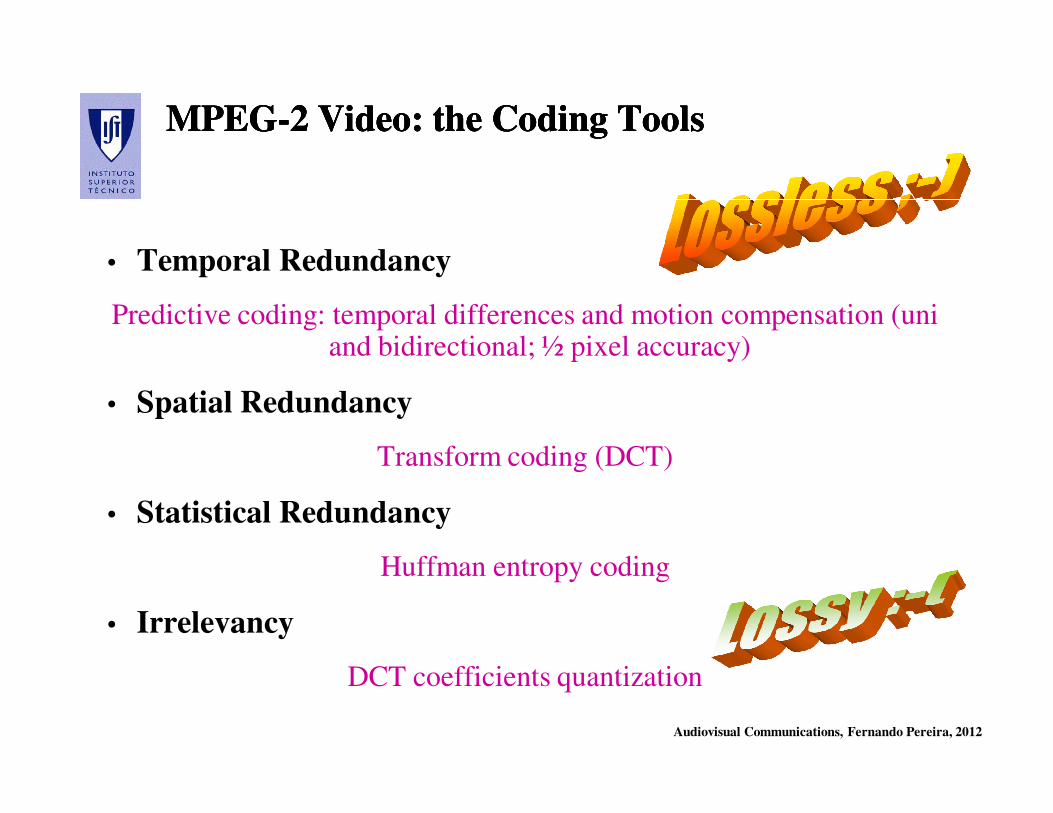
MPEGMPEG--2 Video: the Coding Tools2 Video: the Coding ToolsMPEGMPEG--2 Video: the Coding Tools2 Video: the Coding Tools
• Temporal Redundancy
Predictive coding: temporal differences and motion compensation (uni and bidirectional; ½ pixel accuracy)
• Spatial Redundancy
Transform coding (DCT)
• Statistical Redundancy
Huffman entropy coding
• Irrelevancy
DCT coefficients quantization
Audiovisual Communications, Fernando Pereira, 2012
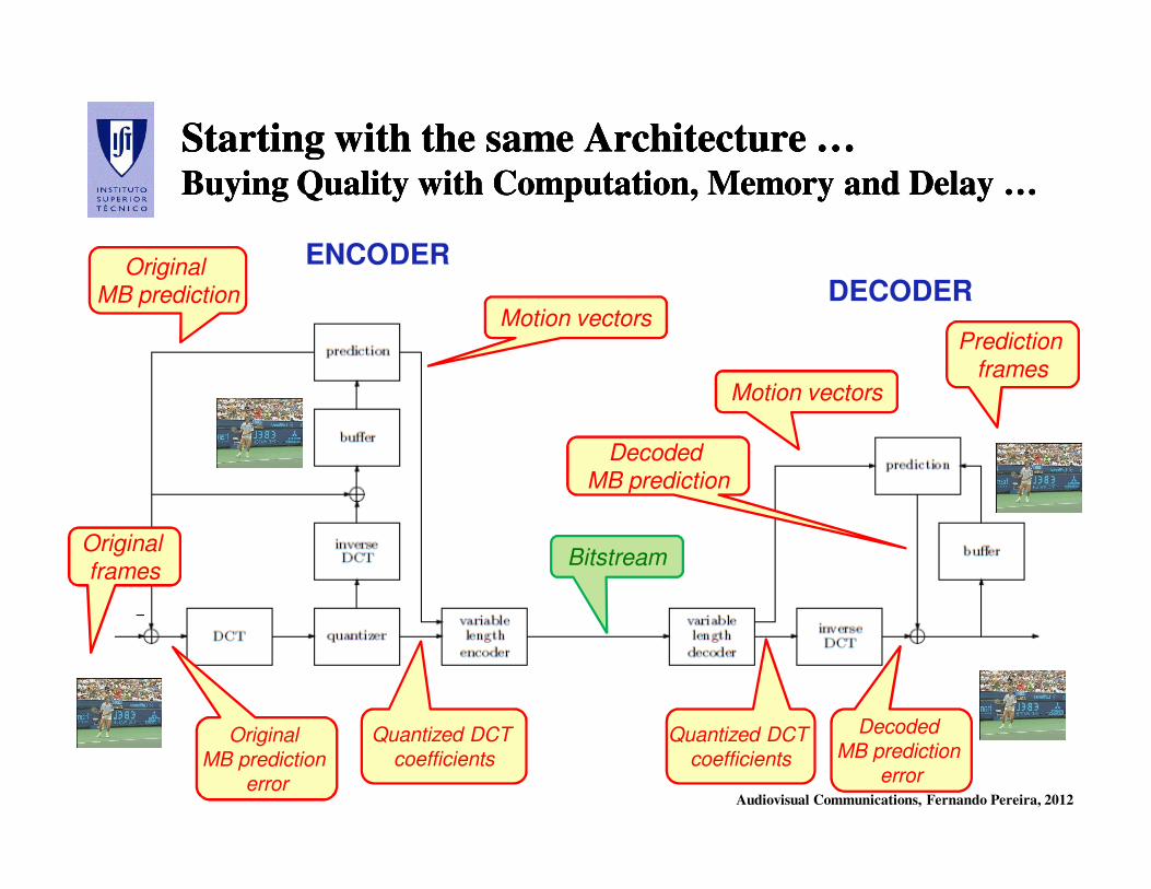
StartingStarting withwith thethe samesame ArchitectureArchitecture ……BuyingBuying QualityQuality withwith ComputationComputation, , MemoryMemory andand DelayDelay … …
StartingStarting withwith thethe samesame ArchitectureArchitecture ……BuyingBuying QualityQuality withwith ComputationComputation, , MemoryMemory andand DelayDelay … …
DECODER
ENCODER
Motion vectors
Motion vectors
Quantized DCT
coefficients
Quantized DCT
coefficients
Decoded
MB prediction
error
Decoded MB prediction
Original MB prediction
Original
MB prediction
error
BitstreamOriginal frames
Prediction frames
Audiovisual Communications, Fernando Pereira, 2012
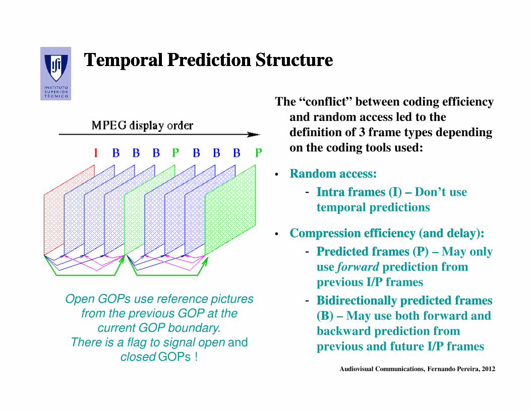
The “conflict” between coding efficiency
and random access led to the
definition of 3 frame types depending
on the coding tools used:
•• Random access: Random access:
-- Intra frames (I) Intra frames (I) –– Don’t use
temporal predictions
•• Compression efficiency (and delay):Compression efficiency (and delay):
-- Predicted frames (P) Predicted frames (P) – May only
use forward prediction from
previous I/P frames
-- BidirectionallyBidirectionally predicted frames predicted frames
(B) (B) – May use both forward and
backward prediction from
previous and future I/P frames
Temporal Prediction StructureTemporal Prediction StructureTemporal Prediction StructureTemporal Prediction Structure
Open GOPs use reference pictures
from the previous GOP at the
current GOP boundary.
There is a flag to signal open and
closed GOPs !

Audiovisual Communications, Fernando Pereira, 2012
MPEGMPEG--2 Video versus MPEG2 Video versus MPEG--1 Video1 VideoMPEGMPEG--2 Video versus MPEG2 Video versus MPEG--1 Video1 Video
The main differences between the
MPEG-1 Video and MPEG-2
Video standards are related to:
•• INTERLACINGINTERLACING - Coding of
interlaced video content with
MPEG-2 Video (which is not
possible with MPEG-1 Video)
•• SCALABILITYSCALABILITY - Availability of
scalable coding in MPEG-2 Video
(only temporal scalabilility with
the I/P/B structure is possible
with MPEG-1 Video)

Audiovisual Communications, Fernando Pereira, 2012
MPEGMPEG--2 Video 2 Video
Interlaced CodingInterlaced Coding
Audiovisual Communications, Fernando Pereira, 2012
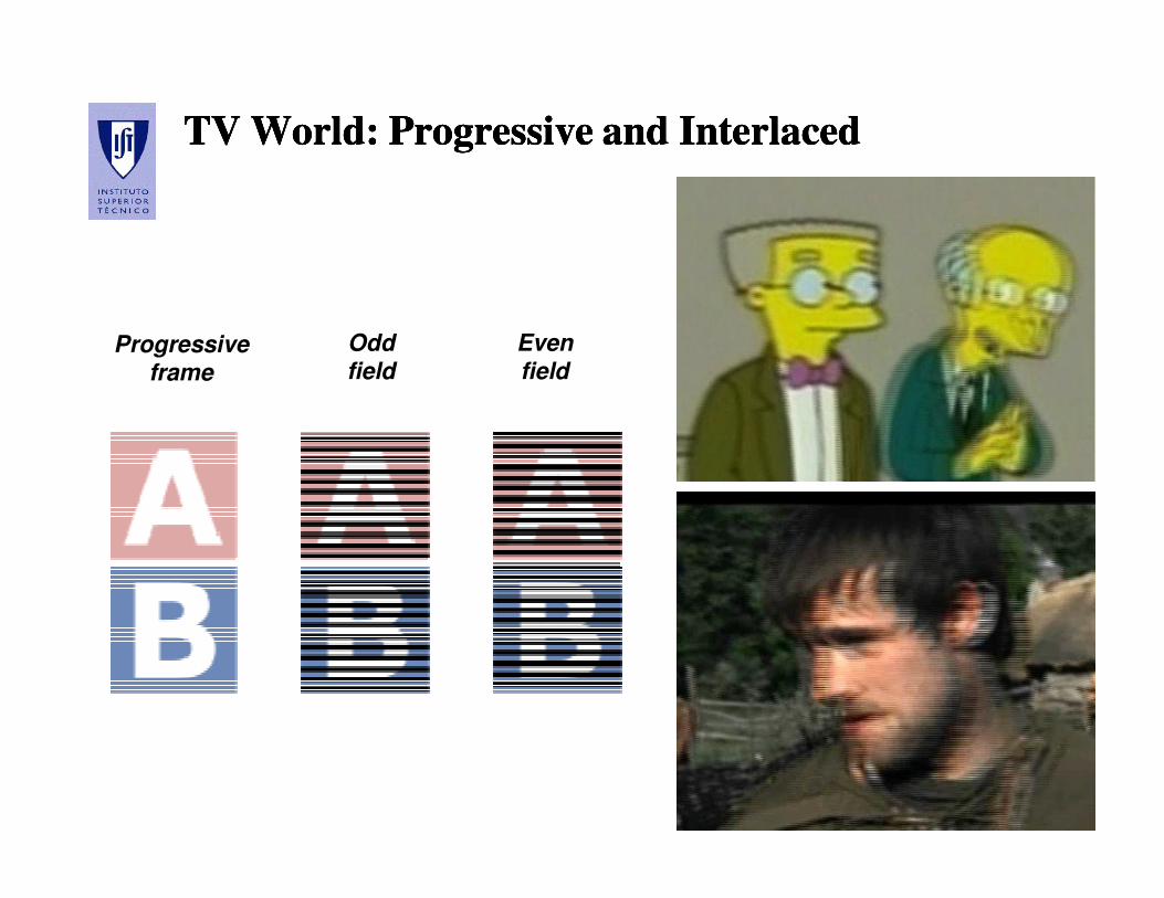
TV TV WorldWorld: : ProgressiveProgressive andand InterlacedInterlacedTV TV WorldWorld: : ProgressiveProgressive andand InterlacedInterlaced
Progressive frame
Odd field
Even field
Audiovisual Communications, Fernando Pereira, 2012
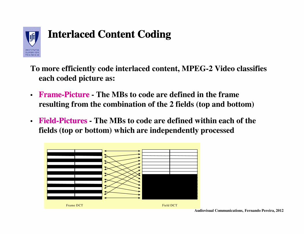
Interlaced Content CodingInterlaced Content CodingInterlaced Content CodingInterlaced Content Coding
To more efficiently code interlaced content, MPEG-2 Video classifies
each coded picture as:
•• FrameFrame--PicturePicture - The MBs to code are defined in the frame
resulting from the combination of the 2 fields (top and bottom)
•• FieldField--Pictures Pictures - The MBs to code are defined within each of the
fields (top or bottom) which are independently processed
Frame DCT Field DCT
Audiovisual Communications, Fernando Pereira, 2012
Main Prediction ModesMain Prediction ModesMain Prediction ModesMain Prediction Modes
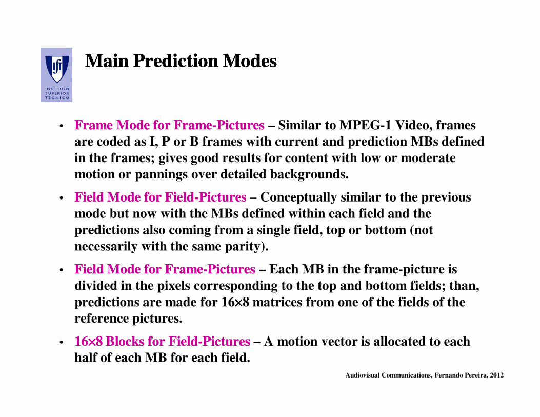
•• Frame Mode for FrameFrame Mode for Frame--PicturesPictures – Similar to MPEG-1 Video, frames
are coded as I, P or B frames with current and prediction MBs defined
in the frames; gives good results for content with low or moderate
motion or pannings over detailed backgrounds.
•• Field Mode for FieldField Mode for Field--PicturesPictures – Conceptually similar to the previous
mode but now with the MBs defined within each field and the
predictions also coming from a single field, top or bottom (not
necessarily with the same parity).
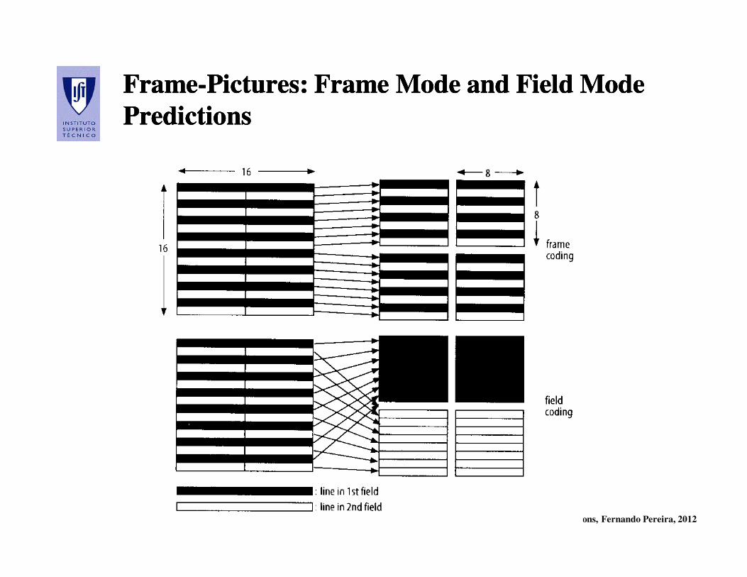
•• Field Mode for FrameField Mode for Frame--Pictures Pictures – Each MB in the frame-picture is
divided in the pixels corresponding to the top and bottom fields; than,
predictions are made for 16××××8 matrices from one of the fields of the
reference pictures.
•• 1616××××××××8 Blocks for Field8 Blocks for Field--PicturesPictures – A motion vector is allocated to each
half of each MB for each field.
Audiovisual Communications, Fernando Pereira, 2012
FrameFrame--Pictures: Frame Mode and Field Mode Pictures: Frame Mode and Field Mode
PredictionsPredictions
FrameFrame--Pictures: Frame Mode and Field Mode Pictures: Frame Mode and Field Mode
PredictionsPredictions

Audiovisual Communications, Fernando Pereira, 2012
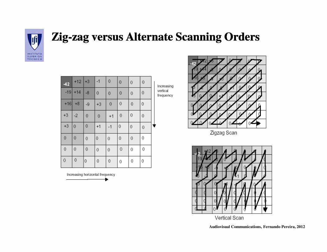
Alternate Scanning Order for Frame Pictures …Alternate Scanning Order for Frame Pictures …Alternate Scanning Order for Frame Pictures …Alternate Scanning Order for Frame Pictures …
For frame-pictures, the correlation between lines may be reduced for the
pictures with more motion. Thus, it is possible to use another scanning
order – ALTERNATE order – where the DCT coefficients corresponding
to the vertical transitions (meaning horizontal edges) are privileged in
terms of scanning order.
Audiovisual Communications, Fernando Pereira, 2012
ZigZig--zagzag versus Alternate Scanning Ordersversus Alternate Scanning OrdersZigZig--zagzag versus Alternate Scanning Ordersversus Alternate Scanning Orders
Audiovisual Communications, Fernando Pereira, 2012
MPEGMPEG--2 Video 2 Video
Scalable CodingScalable Coding
Audiovisual Communications, Fernando Pereira, 2012
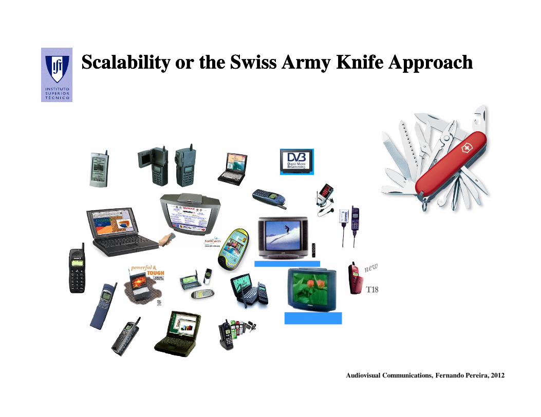
Scalability or the Swiss Army Knife ApproachScalability or the Swiss Army Knife ApproachScalability or the Swiss Army Knife ApproachScalability or the Swiss Army Knife Approach

Audiovisual Communications, Fernando Pereira, 2012
Scalable Coding: the Definition Scalable Coding: the Definition Scalable Coding: the Definition Scalable Coding: the Definition
Scalability is a functionality regarding the useful decoding of parts of
a coded bitstream, ideally
i) while achieving an RD performance at any supported spatial,
temporal, or SNR resolution that is comparable to single-layer (non-
scalable) coding at that particular resolution, and
ii) without significantly increasing the decoding complexity.

Audiovisual Communications, Fernando Pereira, 2012
ScalableScalable HierarchicalHierarchical CodingCodingScalableScalable HierarchicalHierarchical CodingCoding
Base layer
1st enhancement layer
2nd enhancement layer
3rd enhancement layer
Audiovisual Communications, Fernando Pereira, 2012
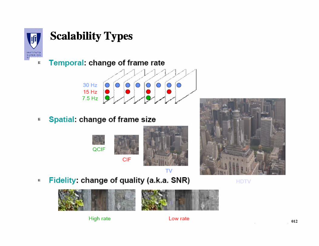
Scalability TypesScalability TypesScalability TypesScalability Types
Audiovisual Communications, Fernando Pereira, 2012
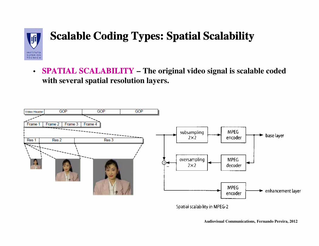
ScalableScalable CodingCoding TypesTypes: : SpatialSpatial ScalabilityScalabilityScalableScalable CodingCoding TypesTypes: : SpatialSpatial ScalabilityScalability
•• SPATIAL SCALABILITYSPATIAL SCALABILITY – The original video signal is scalable coded
with several spatial resolution layers.
Audiovisual Communications, Fernando Pereira, 2012
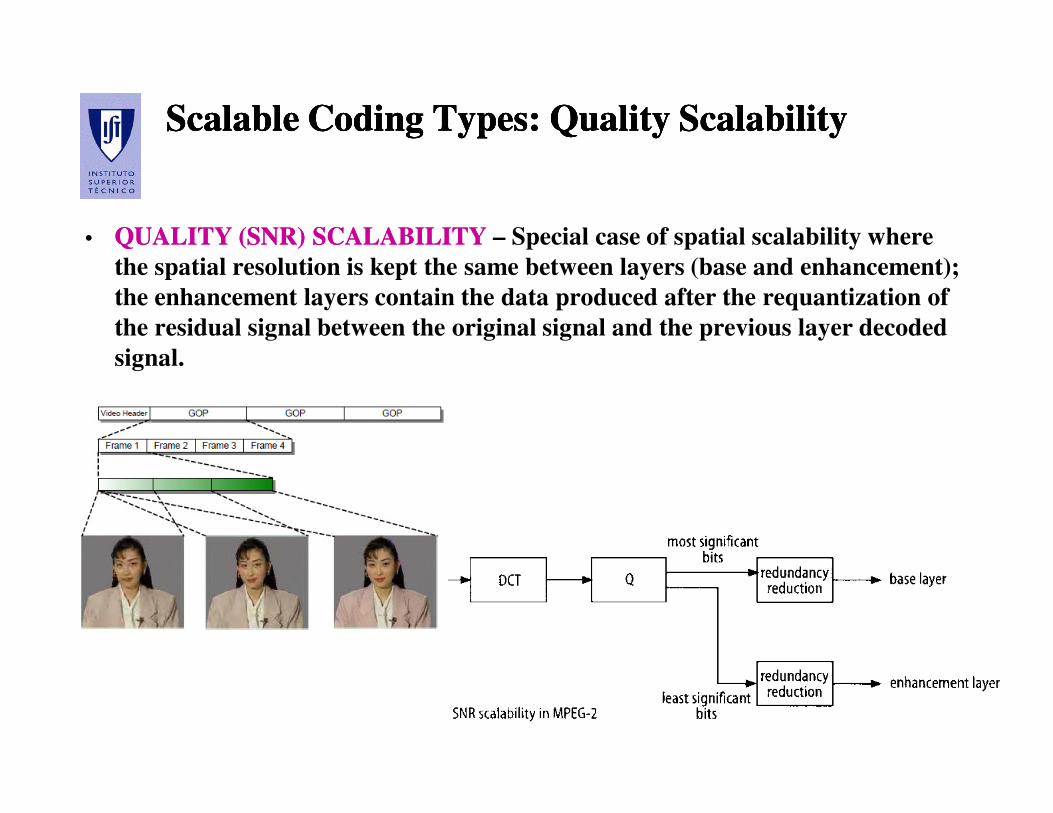
ScalableScalable CodingCoding TypesTypes: : QualityQuality ScalabilityScalabilityScalableScalable CodingCoding TypesTypes: : QualityQuality ScalabilityScalability
•• QUALITY (SNR) SCALABILITYQUALITY (SNR) SCALABILITY – Special case of spatial scalability where
the spatial resolution is kept the same between layers (base and enhancement);
the enhancement layers contain the data produced after the requantization of
the residual signal between the original signal and the previous layer decoded
signal.
Audiovisual Communications, Fernando Pereira, 2012
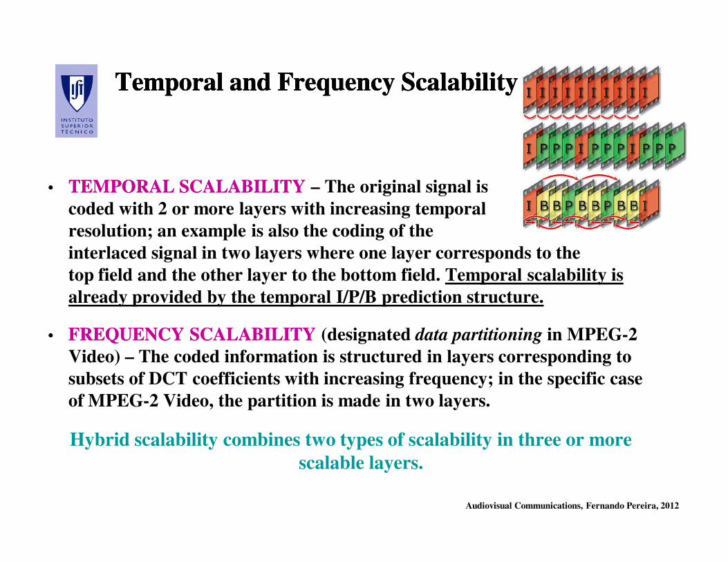
Temporal Temporal andand FrequencyFrequency ScalabilityScalabilityTemporal Temporal andand FrequencyFrequency ScalabilityScalability
•• TEMPORAL SCALABILITYTEMPORAL SCALABILITY – The original signal is scalable
coded with 2 or more layers with increasing temporal
resolution; an example is also the coding of the
interlaced signal in two layers where one layer corresponds to the
top field and the other layer to the bottom field. Temporal scalability is
already provided by the temporal I/P/B prediction structure.
•• FREQUENCY SCALABILITYFREQUENCY SCALABILITY (designated data partitioning in MPEG-2
Video) – The coded information is structured in layers corresponding to
subsets of DCT coefficients with increasing frequency; in the specific case
of MPEG-2 Video, the partition is made in two layers.
Hybrid scalability combines two types of scalability in three or more
scalable layers.
Audiovisual Communications, Fernando Pereira, 2012
MPEGMPEG--2 2 VideoVideo ScalabilityScalability: : WeaknessesWeaknessesMPEGMPEG--2 2 VideoVideo ScalabilityScalability: : WeaknessesWeaknesses
MPEG-2 Video scalability was not successful due to:
• Characteristics of traditional video transmission systems where a fixed
bandwidth was guaranteed and thus no dynamic variations or
heterogeneous consumptions had to be accommodated
• HDTV did not explode as flat displays did not emerge and thus
standard definition was still the single solution
• Significant penalty in compression efficiency regarding non-scalable
coding solutions, meaning much larger bitrate for the same maximum
quality/resolution
• Large increase in decoder complexity regarding non-scalable coding
solutions as all layers up to the target layer have to be decoded and
accumulated
Audiovisual Communications, Fernando Pereira, 2012
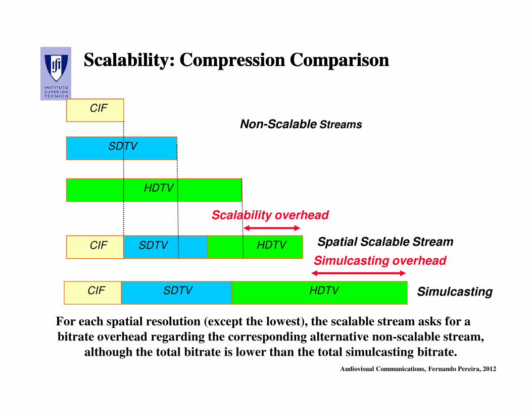
Scalability: Compression ComparisonScalability: Compression ComparisonScalability: Compression ComparisonScalability: Compression Comparison
For each spatial resolution (except the lowest), the scalable stream asks for a
bitrate overhead regarding the corresponding alternative non-scalable stream,
although the total bitrate is lower than the total simulcasting bitrate.
Non-Scalable Streams
Spatial Scalable Stream
CIF
SDTV
HDTV
CIF SDTV HDTV
CIF SDTV HDTV Simulcasting
Scalability overhead
Simulcasting overhead
Audiovisual Communications, Fernando Pereira, 2012
Combining the Combining the
Coding Tools ...Coding Tools ...
Audiovisual Communications, Fernando Pereira, 2012
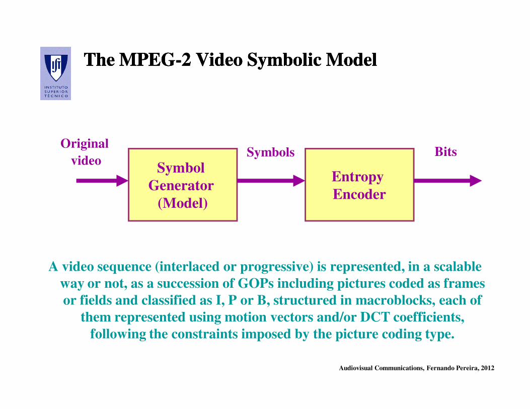
The MPEGThe MPEG--2 Video Symbolic Model2 Video Symbolic ModelThe MPEGThe MPEG--2 Video Symbolic Model2 Video Symbolic Model
A video sequence (interlaced or progressive) is represented, in a scalable
way or not, as a succession of GOPs including pictures coded as frames
or fields and classified as I, P or B, structured in macroblocks, each of
them represented using motion vectors and/or DCT coefficients,
following the constraints imposed by the picture coding type.
Symbol
Generator
(Model)
Entropy
Encoder
Original
videoSymbols Bits
Audiovisual Communications, Fernando Pereira, 2012
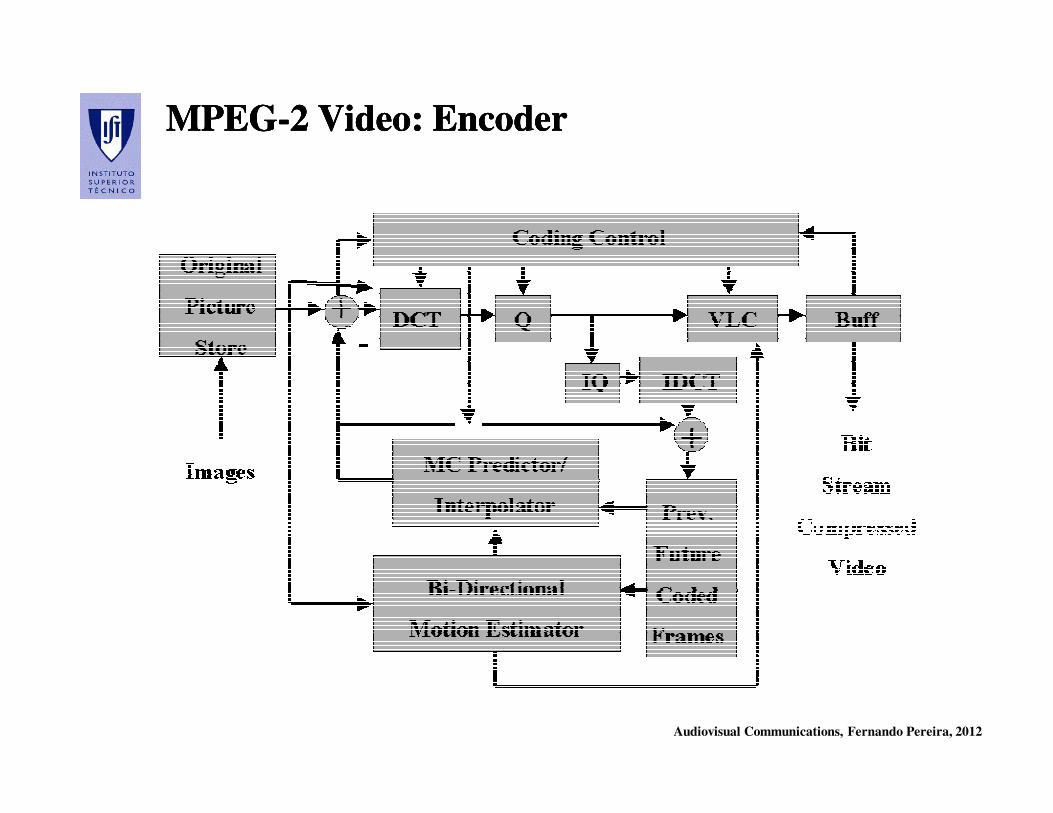
MPEGMPEG--2 Video: Encoder2 Video: EncoderMPEGMPEG--2 Video: Encoder2 Video: Encoder

Audiovisual Communications, Fernando Pereira, 2012
MPEGMPEG--2 Video: Decoder2 Video: DecoderMPEGMPEG--2 Video: Decoder2 Video: Decoder
Audiovisual Communications, Fernando Pereira, 2012
MPEGMPEG--2 Video Syntax 2 Video Syntax MPEGMPEG--2 Video Syntax 2 Video Syntax
Audiovisual Communications, Fernando Pereira, 2012
MPEGMPEG--2 Video 2 Video
Profiles and LevelsProfiles and Levels
Audiovisual Communications, Fernando Pereira, 2012
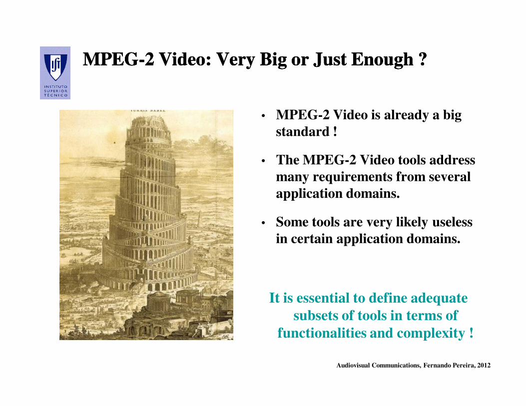
MPEGMPEG--2 2 VideoVideo: : VeryVery Big Big oror Just EnoughJust Enough ??MPEGMPEG--2 2 VideoVideo: : VeryVery Big Big oror Just EnoughJust Enough ??
• MPEG-2 Video is already a big
standard !
• The MPEG-2 Video tools address
many requirements from several
application domains.
• Some tools are very likely useless
in certain application domains.
It is essential to define adequate
subsets of tools in terms of
functionalities and complexity !
Audiovisual Communications, Fernando Pereira, 2012
Profiles and Levels: Why ?Profiles and Levels: Why ?Profiles and Levels: Why ?Profiles and Levels: Why ?
The profile and level concepts were first adopted by the MPEG-2 Video
standard and they provide a trade-off between:
•• Implementation complexityImplementation complexity for a certain class of applications
•• InteroperabilityInteroperability between applications
while guaranteeing the necessary compression efficiency capability
required by the class of applications in question and limiting the codec
complexity and associated costs.
•• PROFILEPROFILE – Subset of coding tools corresponding to the
requirements of a certain class of applications.
•• LEVELLEVEL – Establishes for each profile constraints on relevant
coding parameters, e.g. bitrate and memory
Audiovisual Communications, Fernando Pereira, 2012
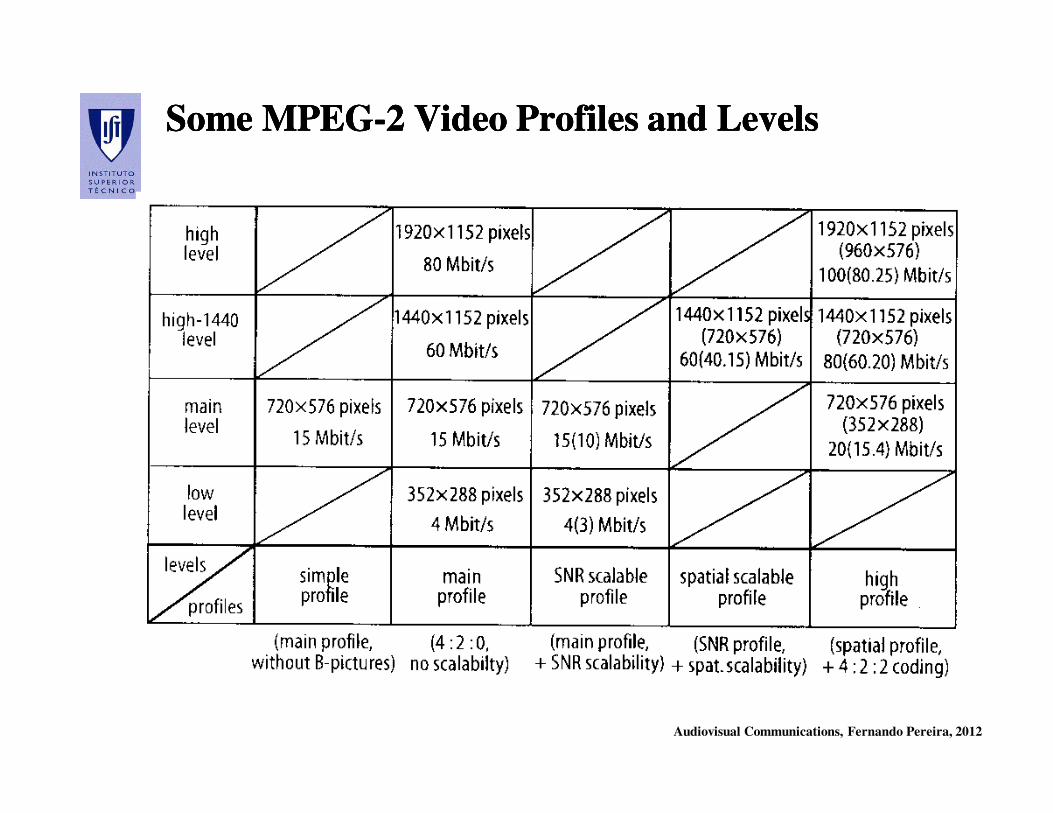
Some MPEGSome MPEG--2 Video Profiles and Levels2 Video Profiles and LevelsSome MPEGSome MPEG--2 Video Profiles and Levels2 Video Profiles and Levels
Audiovisual Communications, Fernando Pereira, 2012
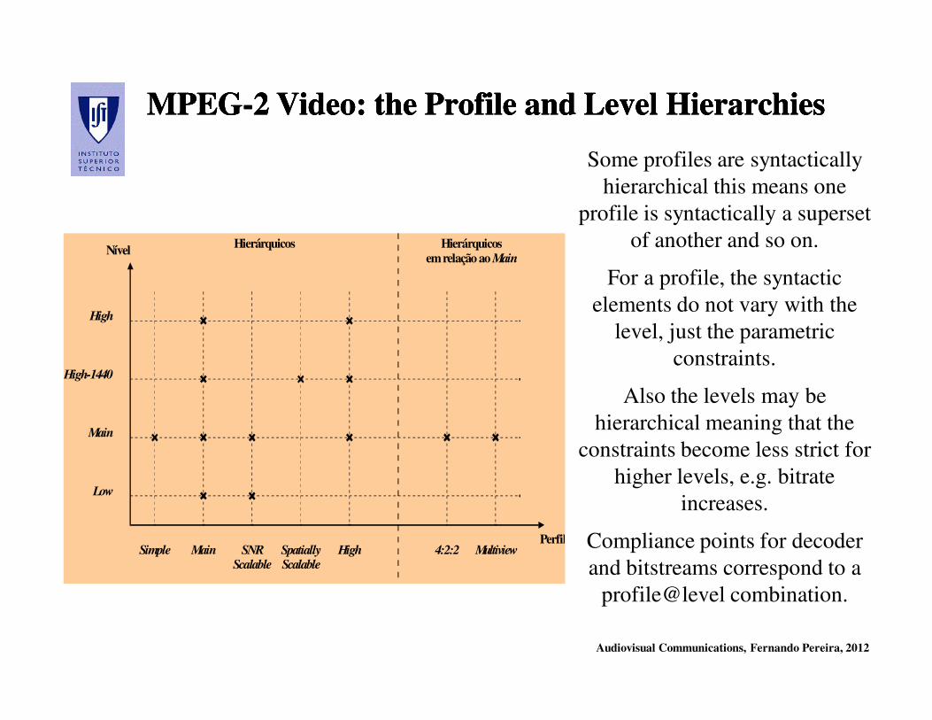
MPEGMPEG--2 Video: the Profile and Level 2 Video: the Profile and Level HierarchiesHierarchiesMPEGMPEG--2 Video: the Profile and Level 2 Video: the Profile and Level HierarchiesHierarchies
Low
Main
High-1440
High
Nível
PerfilSimple Main SNR
ScalableSpatiallyScalable
High 4:2:2 Multiview
Hierárquicos Hierárquicosemrelação ao Main
Some profiles are syntactically
hierarchical this means one
profile is syntactically a superset
of another and so on.
For a profile, the syntactic
elements do not vary with the
level, just the parametric
constraints.
Also the levels may be
hierarchical meaning that the
constraints become less strict for
higher levels, e.g. bitrate
increases.
Compliance points for decoder
and bitstreams correspond to a
profile@level combination.

Audiovisual Communications, Fernando Pereira, 2012
Profiles and Profiles and
Levels Levels
ClassificationClassification
Profiles and Profiles and
Levels Levels
ClassificationClassification
• If an encoder produces a bitstream which is over, even if only slightly, the predefined limits
for a certain profile and/or level, than it is classified with the profile or/and level immediately
above (to guarantee decoding).
• If the decoding capabilities of a decoder are below, even if only slightly, from those
predefined for a certain profile and/or level, than it is classified with the profile and/or level
immediately below (to guarantee decoding).
This type of classification is important for the deployment and compliance of MPEGThis type of classification is important for the deployment and compliance of MPEG--2 2
Video content and decoders ! Video content and decoders !
Audiovisual Communications, Fernando Pereira, 2012
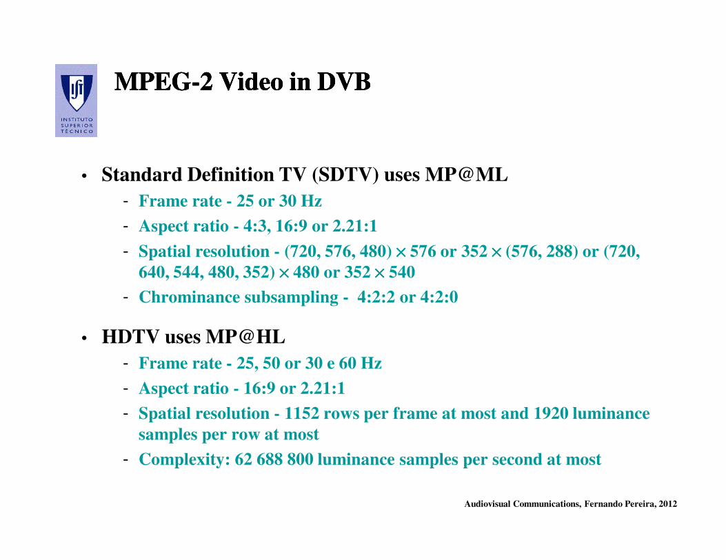
MPEGMPEG--2 Video in DVB2 Video in DVBMPEGMPEG--2 Video in DVB2 Video in DVB
• Standard Definition TV (SDTV) uses MP@ML
- Frame rate - 25 or 30 Hz
- Aspect ratio - 4:3, 16:9 or 2.21:1
- Spatial resolution - (720, 576, 480) ×××× 576 or 352 ×××× (576, 288) or (720,
640, 544, 480, 352) ×××× 480 or 352 ×××× 540
- Chrominance subsampling - 4:2:2 or 4:2:0
• HDTV uses MP@HL
- Frame rate - 25, 50 or 30 e 60 Hz
- Aspect ratio - 16:9 or 2.21:1
- Spatial resolution - 1152 rows per frame at most and 1920 luminance
samples per row at most
- Complexity: 62 688 800 luminance samples per second at most

Audiovisual Communications, Fernando Pereira, 2012
MPEGMPEG--2 Standard 2 Standard
Part 3: AudioPart 3: Audio
Audiovisual Communications, Fernando Pereira, 2012
AudioAudio inin MPEGMPEG--2: Objective 2: Objective AudioAudio inin MPEGMPEG--2: Objective 2: Objective
Efficient high quality audio coding targeting the broadcasting and Efficient high quality audio coding targeting the broadcasting and
storage of TV or TV like signals. storage of TV or TV like signals.
There are two parts in the MPEG-2 standard specifying audio codecs:
•• AudioAudio ((PartPart 3)3) – Codes up to 5 (full) channels + 1 low frequency channel
with high quality, at 384 kbit/s or less per channel, using the following
additional sampling rates: 16, 22.05 and 24 kHz; offers backward and
forward compatibilities with MPEG-1 Audio, thus the name of MPEGMPEG--2 2
AudioAudio BackwardBackward CompatibleCompatible (BC).
•• AdvancedAdvanced AudioAudio CodingCoding ((PartPart 7)7) – Gives up on any compatibility with
MPEG-1 Audio, improving its rate-distortion performance, thus reaching
higher quality for the same rate; codes 1 to 48 canais, with sampling rates
from 8 to 96 kHz; it was initially designated as MPEGMPEG--2 2 AudioAudio NonNon--
BackwardBackward CompatibleCompatible (NBC), now AdvancedAdvanced AudioAudio CodingCoding (AAC).
Audiovisual Communications, Fernando Pereira, 2012
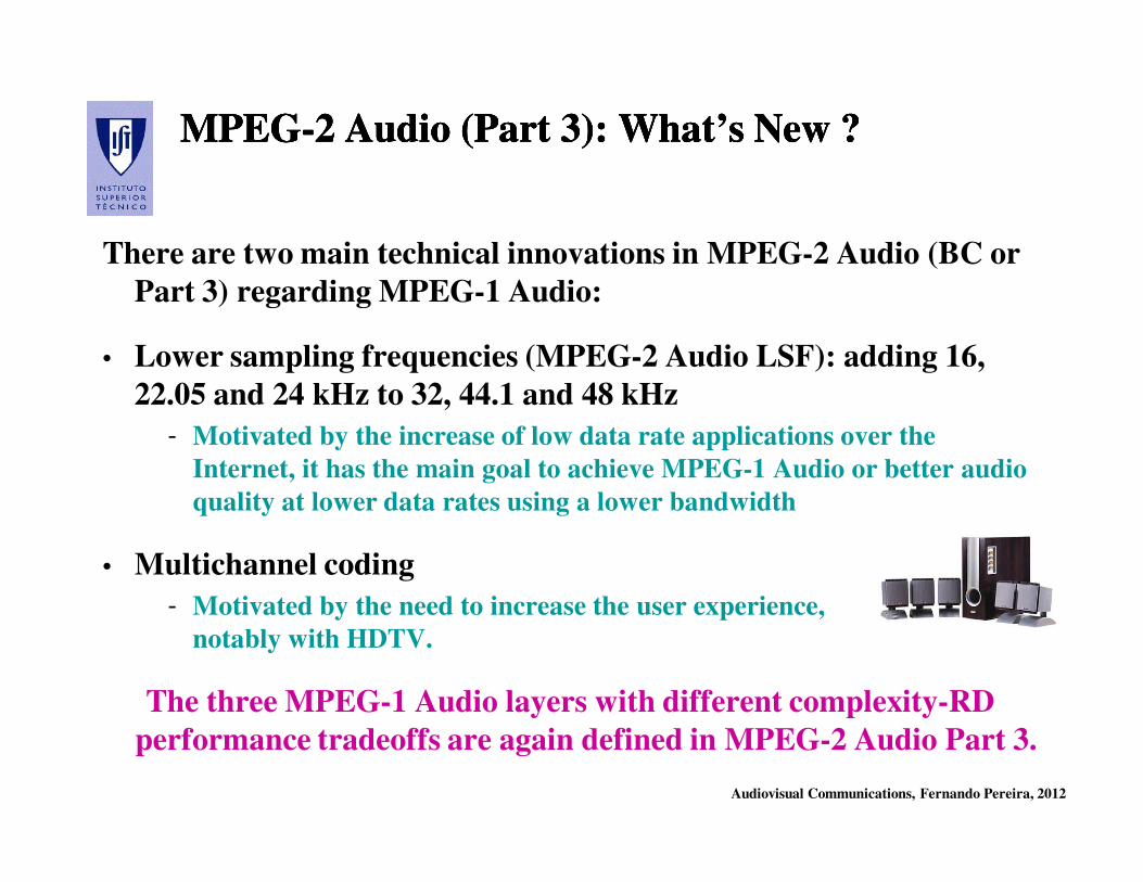
MPEGMPEG--2 Audio (Part 3): What’s New ?2 Audio (Part 3): What’s New ?MPEGMPEG--2 Audio (Part 3): What’s New ?2 Audio (Part 3): What’s New ?
There are two main technical innovations in MPEG-2 Audio (BC or
Part 3) regarding MPEG-1 Audio:
• Lower sampling frequencies (MPEG-2 Audio LSF): adding 16,
22.05 and 24 kHz to 32, 44.1 and 48 kHz
- Motivated by the increase of low data rate applications over the
Internet, it has the main goal to achieve MPEG-1 Audio or better audio
quality at lower data rates using a lower bandwidth
• Multichannel coding
- Motivated by the need to increase the user experience,
notably with HDTV.
The three MPEG-1 Audio layers with different complexity-RD
performance tradeoffs are again defined in MPEG-2 Audio Part 3.
Audiovisual Communications, Fernando Pereira, 2012
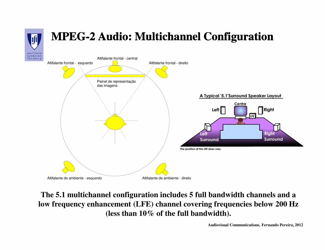
MPEGMPEG--2 2 AudioAudio: : MultichannelMultichannel ConfigurationConfigurationMPEGMPEG--2 2 AudioAudio: : MultichannelMultichannel ConfigurationConfiguration
Painel de representaçãodas imagens
Altifalante frontal - esquerdo Altifalante frontal - direito
Altifalante frontal - central
Altifalante de ambiente - esquerdo Altifalante de ambiente - direito
The 5.1 multichannel configuration includes 5 full bandwidth channels and a
low frequency enhancement (LFE) channel covering frequencies below 200 Hz
(less than 10% of the full bandwidth).
Audiovisual Communications, Fernando Pereira, 2012
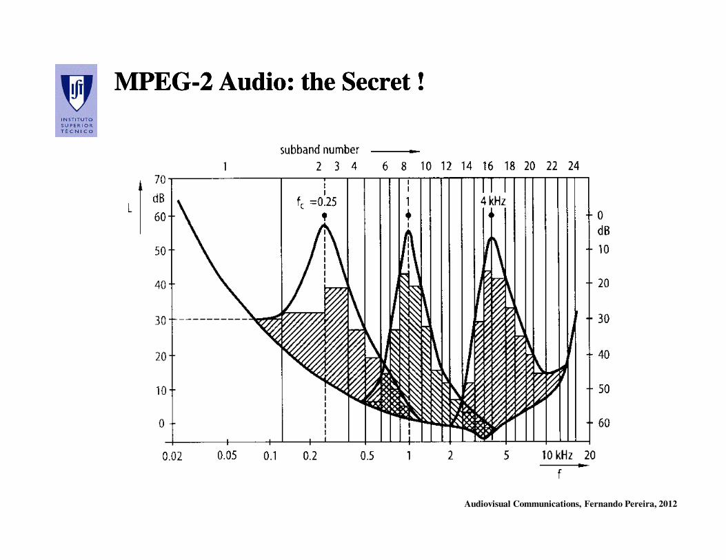
MPEGMPEG--2 Audio: the Secret !2 Audio: the Secret !MPEGMPEG--2 Audio: the Secret !2 Audio: the Secret !

Audiovisual Communications, Fernando Pereira, 2012
MPEGMPEG--2 and MPEG2 and MPEG--1 Audio Compatibility1 Audio CompatibilityMPEGMPEG--2 and MPEG2 and MPEG--1 Audio Compatibility1 Audio Compatibility
Backward compatibility is provided by means of a MPEG-1 Audio
compliant stereo pair and additional MPEG-2 Audio compliant
data for the other channels.
Audiovisual Communications, Fernando Pereira, 2012
MPEGMPEG--1/2 Audio in DVB 1/2 Audio in DVB MPEGMPEG--1/2 Audio in DVB 1/2 Audio in DVB
• All DVB audio decoders use MPEG-1 Audio, Layers 1 and 2, or
MPEG-2 Audio Part 3 (BC), Layers 1 and 2.
• For MPEG-1 Audio, it is recommended to use Layer 2.
• Due to forward compatibility, it is possible to recover, with a
MPEG-1 Audio decoder, a stereo pair from a multichannel
MPEG-2 Audio BC coded bitstream (through downmixing).
• Sampling frequencies: 32, 44.1 and 48 kHz.

Audiovisual Communications, Fernando Pereira, 2012
New Systems and … Business Models …New Systems and … Business Models …New Systems and … Business Models …New Systems and … Business Models …
iPod is able to play the following audio formats: MP3, WAV,
AAC, Protected AACProtected AAC, AIFF and Apple Lossless.
Audiovisual Communications, Fernando Pereira, 2012
Technologies Developed Technologies Developed
by DVBby DVB
Audiovisual Communications, Fernando Pereira, 2012
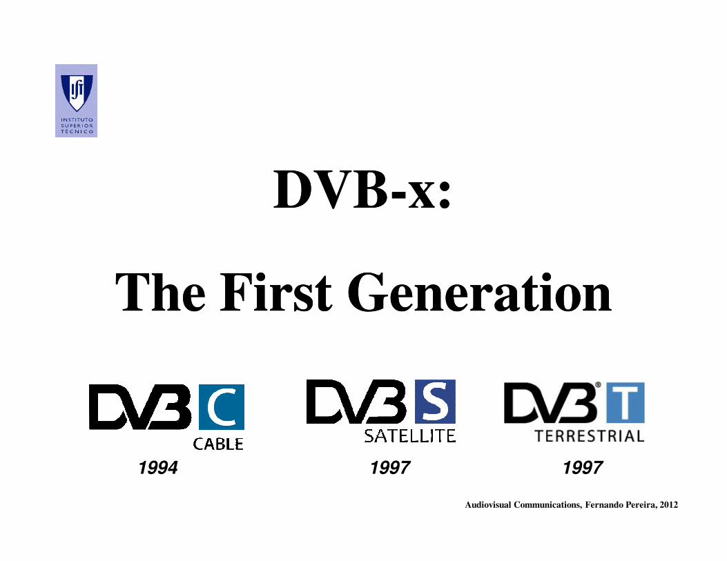
DVBDVB--x: x:
The First GenerationThe First Generation
1994 1997 1997
Audiovisual Communications, Fernando Pereira, 2012
DVBDVB--x Channel Codingx Channel Coding
Audiovisual Communications, Fernando Pereira, 2012
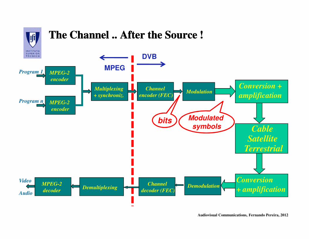
The Channel .. After the Source !The Channel .. After the Source !The Channel .. After the Source !The Channel .. After the Source !
Conversion
+ amplification
CableSatellite
Terrestrial
Conversion +
amplification
Video
Audio
Program 1
Program n
MPEG-2
encoder
MPEG-2
encoder
Multiplexing
+ synchroniz.
MPEG-2
decoderDemultiplexing
Modulation
Demodulation
Channel
encoder (FEC)
Channel
decoder (FEC)
MPEG
DVB
bits Modulated
symbols
Audiovisual Communications, Fernando Pereira, 2012
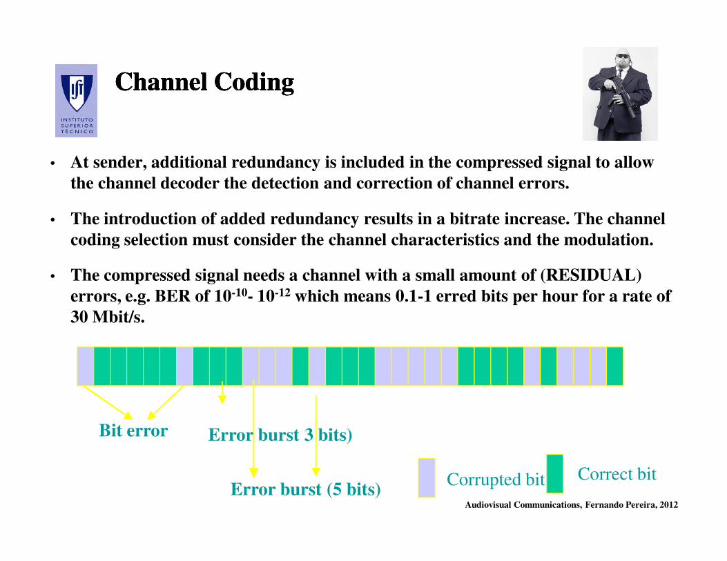
Channel CodingChannel CodingChannel CodingChannel Coding
• At sender, additional redundancy is included in the compressed signal to allow
the channel decoder the detection and correction of channel errors.
• The introduction of added redundancy results in a bitrate increase. The channel
coding selection must consider the channel characteristics and the modulation.
• The compressed signal needs a channel with a small amount of (RESIDUAL)
errors, e.g. BER of 10-10- 10-12 which means 0.1-1 erred bits per hour for a rate of
30 Mbit/s.
Corrupted bit Correct bit
Bit error Error burst 3 bits)
Error burst (5 bits)
Audiovisual Communications, Fernando Pereira, 2012
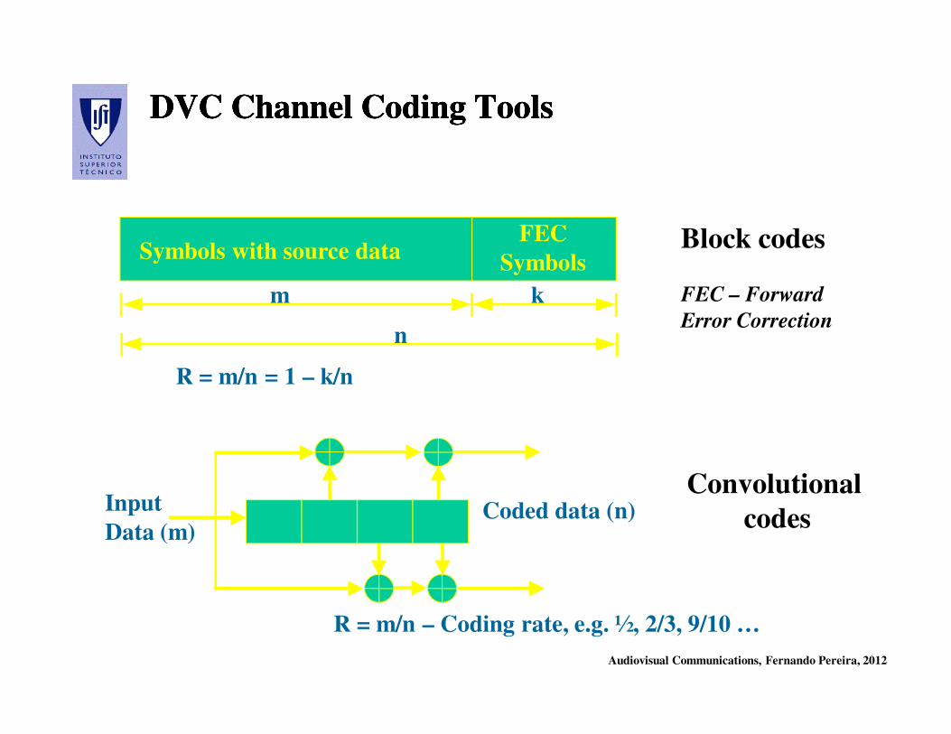
DVC Channel Coding ToolsDVC Channel Coding ToolsDVC Channel Coding ToolsDVC Channel Coding Tools
Symbols with source dataFEC
Symbols
m k
n
R = m/n = 1 – k/n
R = m/n – Coding rate, e.g. ½, 2/3, 9/10 …
Input
Data (m)Coded data (n)
Block codes
FEC – Forward
Error Correction
Convolutional
codes
Audiovisual Communications, Fernando Pereira, 2012
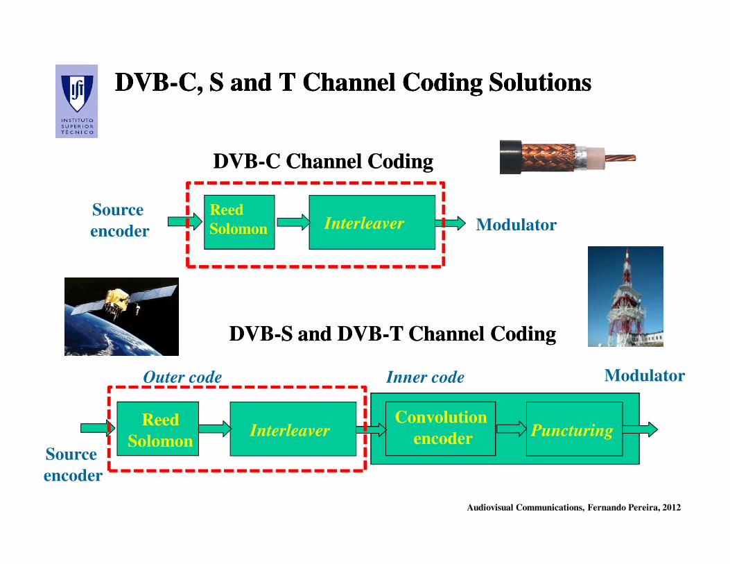
DVBDVB--C, S and T Channel Coding SolutionsC, S and T Channel Coding SolutionsDVBDVB--C, S and T Channel Coding SolutionsC, S and T Channel Coding Solutions
Reed
Solomon Interleaver
Convolution
encoder Puncturing
Outer code Inner code
Source
encoder
DVBDVB--S and DVBS and DVB--T Channel CodingT Channel Coding
DVBDVB--C Channel CodingC Channel Coding
Reed
Solomon InterleaverSource
encoder Modulator
Modulator

Audiovisual Communications, Fernando Pereira, 2012
InterleavingInterleavingInterleavingInterleaving
The interleaver does not provide error correction capabilities by
itself; it rather reorganizes the symbols to have burst and bit errors
more efficiently corrected when also using a channel code, e.g. a RS
code, at the cost of delay, memory and complexity.
= 1 symbol = 1 erred symbol
Block channel
encoder
Convolutional
encoderInterleaver
Source
encoder
Modulator
Reading
Writing Writing Reading
Sender Receiver
Audiovisual Communications, Fernando Pereira, 2012
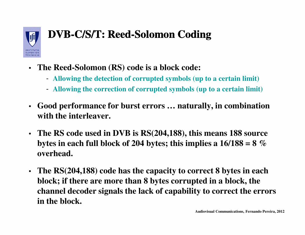
DVBDVB--C/S/T: ReedC/S/T: Reed--Solomon CodingSolomon CodingDVBDVB--C/S/T: ReedC/S/T: Reed--Solomon CodingSolomon Coding
• The Reed-Solomon (RS) code is a block code:
- Allowing the detection of corrupted symbols (up to a certain limit)
- Allowing the correction of corrupted symbols (up to a certain limit)
• Good performance for burst errors … naturally, in combination
with the interleaver.
• The RS code used in DVB is RS(204,188), this means 188 source
bytes in each full block of 204 bytes; this implies a 16/188 = 8 %
overhead.
• The RS(204,188) code has the capacity to correct 8 bytes in each
block; if there are more than 8 bytes corrupted in a block, the
channel decoder signals the lack of capability to correct the errors
in the block.
Audiovisual Communications, Fernando Pereira, 2012
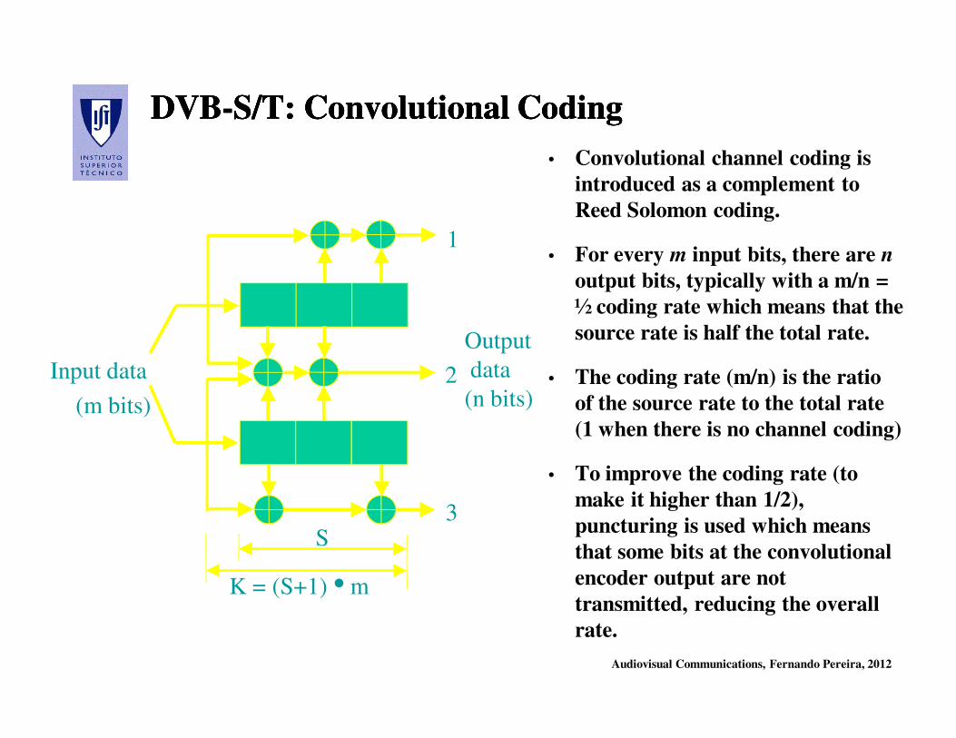
DVBDVB--S/T: S/T: ConvolutionalConvolutional CodingCodingDVBDVB--S/T: S/T: ConvolutionalConvolutional CodingCoding
• Convolutional channel coding is
introduced as a complement to
Reed Solomon coding.
• For every m input bits, there are n
output bits, typically with a m/n =
½ coding rate which means that the
source rate is half the total rate.
• The coding rate (m/n) is the ratio
of the source rate to the total rate
(1 when there is no channel coding)
• To improve the coding rate (to
make it higher than 1/2),
puncturing is used which means
that some bits at the convolutional
encoder output are not
transmitted, reducing the overall
rate.
1
2
3S
K = (S+1) • m
Input data
(m bits)
Output
data
(n bits)
Audiovisual Communications, Fernando Pereira, 2012
Puncturing for Coding Rate FlexibilityPuncturing for Coding Rate FlexibilityPuncturing for Coding Rate FlexibilityPuncturing for Coding Rate Flexibility
• Puncturing is the process of removing some of the parity bits after encoding
with an error-correction code. This has the same effect as encoding with an
error-correction code with a higher rate, or less redundancy.
• However, with puncturing the same decoder can be used regardless of how
many bits have been punctured; thus, puncturing considerably increases the
flexibility of the system without significantly increasing its complexity.
• In some cases, a pre-defined pattern of puncturing is used in an encoder.
Then, the inverse operation, known as depuncturing, is implemented by the
decoder.
• DVB-S/T – In the convolutional encoder, the output rate doubles the input
rate; to reduce this high redundancy at least in part, the output data is
punctured, i.e. defined bits of the output data are deleted to reduce the
output data rate.
Audiovisual Communications, Fernando Pereira, 2012
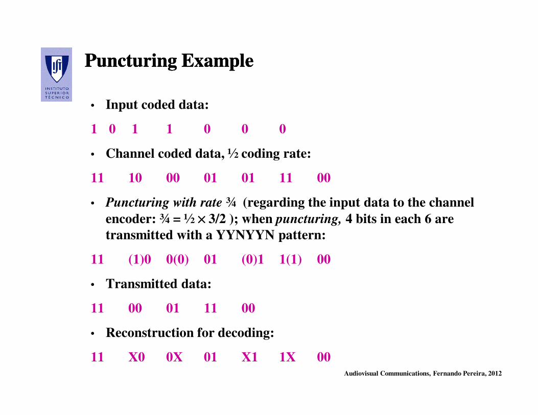
Puncturing ExamplePuncturing ExamplePuncturing ExamplePuncturing Example
• Input coded data:
1 0 1 1 0 0 0
• Channel coded data, ½ coding rate:
11 10 00 01 01 11 00
• Puncturing with rate ¾ (regarding the input data to the channel
encoder: ¾ = ½ ×××× 3/2 ); when puncturing, 4 bits in each 6 are
transmitted with a YYNYYN pattern:
11 (1)0 0(0) 01 (0)1 1(1) 00
• Transmitted data:
11 00 01 11 00
• Reconstruction for decoding:
11 X0 0X 01 X1 1X 00
Audiovisual Communications, Fernando Pereira, 2012
DVBDVB--x Modulationx Modulation
Audiovisual Communications, Fernando Pereira, 2012
About Modulation …About Modulation …About Modulation …About Modulation …
• Factors to consider when selecting a modulation:
- Channel characteristics
- Spectral efficiency, i.e. how many bits are transmitted per Hertz
- Robustness to channel distortion
- Tolerance to transmitter and receiver imperfections
- Minimization of requirements for interference protection
• Main basic digital modulation techniques:
- Amplitude modulation (ASK)
- Frequency modulation (FSK)
- Phase modulation (PSK)
- Combined amplitude and phase modulation (QAM)
Audiovisual Communications, Fernando Pereira, 2012
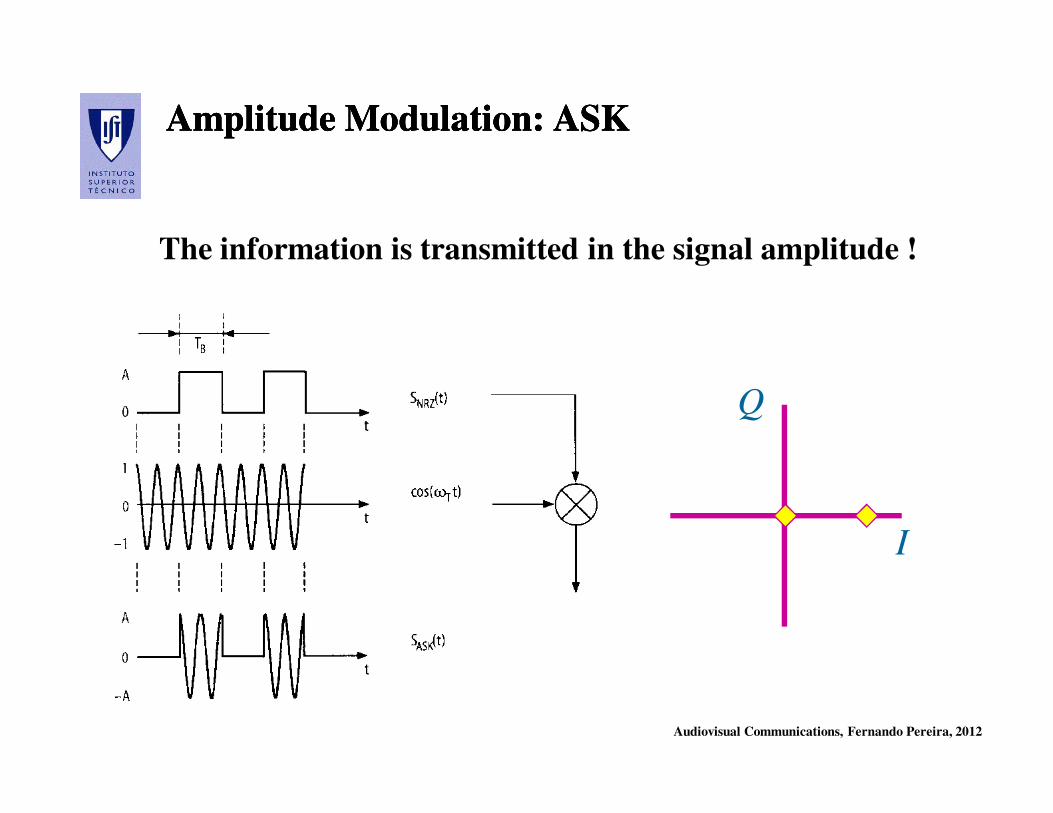
Amplitude Modulation: ASKAmplitude Modulation: ASKAmplitude Modulation: ASKAmplitude Modulation: ASK
The information is transmitted in the signal amplitude !
I
Q
Audiovisual Communications, Fernando Pereira, 2012
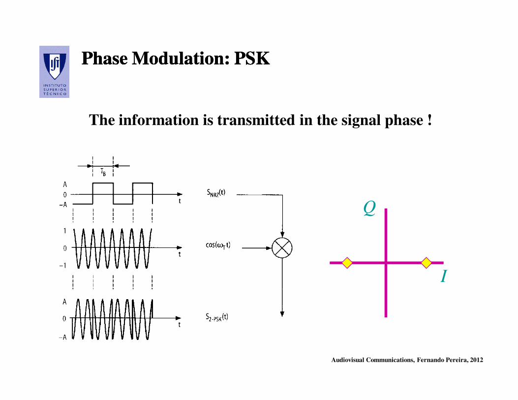
Phase Modulation: PSKPhase Modulation: PSKPhase Modulation: PSKPhase Modulation: PSK
The information is transmitted in the signal phase !
I
Q
Audiovisual Communications, Fernando Pereira, 2012
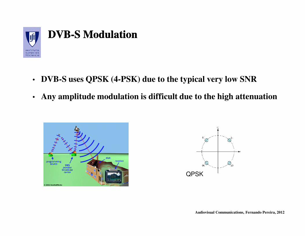
DVBDVB--S ModulationS ModulationDVBDVB--S ModulationS Modulation
• DVB-S uses QPSK (4-PSK) due to the typical very low SNR
• Any amplitude modulation is difficult due to the high attenuation
QPSK

Audiovisual Communications, Fernando Pereira, 2012
QAM ModulationQAM ModulationQAM ModulationQAM Modulation
The digital signal is decomposed into 2 multilevel components
corresponding to two carriers I and Q (in quadrature); the
information is transmitted in the signal amplitude and phase,
simultaneously.
Audiovisual Communications, Fernando Pereira, 2012
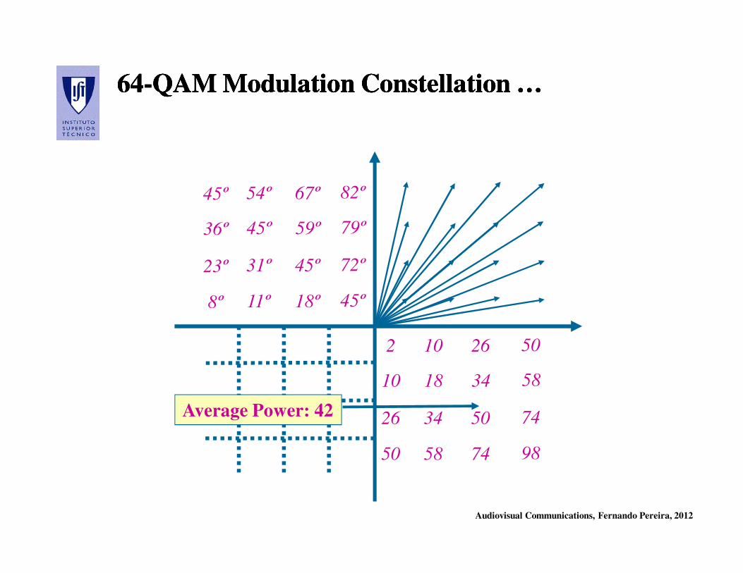
6464--QAM Modulation Constellation …QAM Modulation Constellation …6464--QAM Modulation Constellation …QAM Modulation Constellation …
2 2610 50
26 5034 74
50 7458 98
10 3418 58
45º 67º54º 82º
23º 45º31º 72º
8º 18º11º 45º
36º 59º45º 79º
Average Power: 42
Audiovisual Communications, Fernando Pereira, 2012
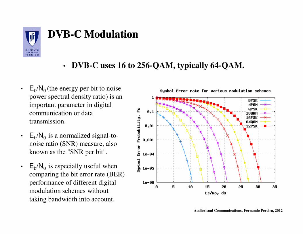
DVBDVB--C ModulationC ModulationDVBDVB--C ModulationC Modulation
• DVB-C uses 16 to 256-QAM, typically 64-QAM.
• Eb/N0 (the energy per bit to noise
power spectral density ratio) is an
important parameter in digital
communication or data
transmission.
• Eb/N0 is a normalized signal-to-
noise ratio (SNR) measure, also
known as the "SNR per bit".
• Eb/N0 is especially useful when
comparing the bit error rate (BER)
performance of different digital
modulation schemes without
taking bandwidth into account.
Audiovisual Communications, Fernando Pereira, 2012
DVB DVB SystemsSystems ArchitectureArchitectureDVB DVB SystemsSystems ArchitectureArchitecture

Audiovisual Communications, Fernando Pereira, 2012
DVBDVB--T: T:
TerrestrialTerrestrial BroadastingBroadasting

Audiovisual Communications, Fernando Pereira, 2012
Current Situation: Current Situation:
Terrestrial TV Terrestrial TV
Transmission Transmission
Current Situation: Current Situation:
Terrestrial TV Terrestrial TV
Transmission Transmission
Until 2008, there were two
terrestrial broadcasting networks
in Portugal:
• PT Comunicações (green in the
map) network which has the
network that was initially from
RTP and TDP
• RETI, Rede Teledifusora
Independente, (blue in the map)
network which developed from
the radio network from Rádio
Renascença (bought by PT in
2008)
Audiovisual Communications, Fernando Pereira, 2012
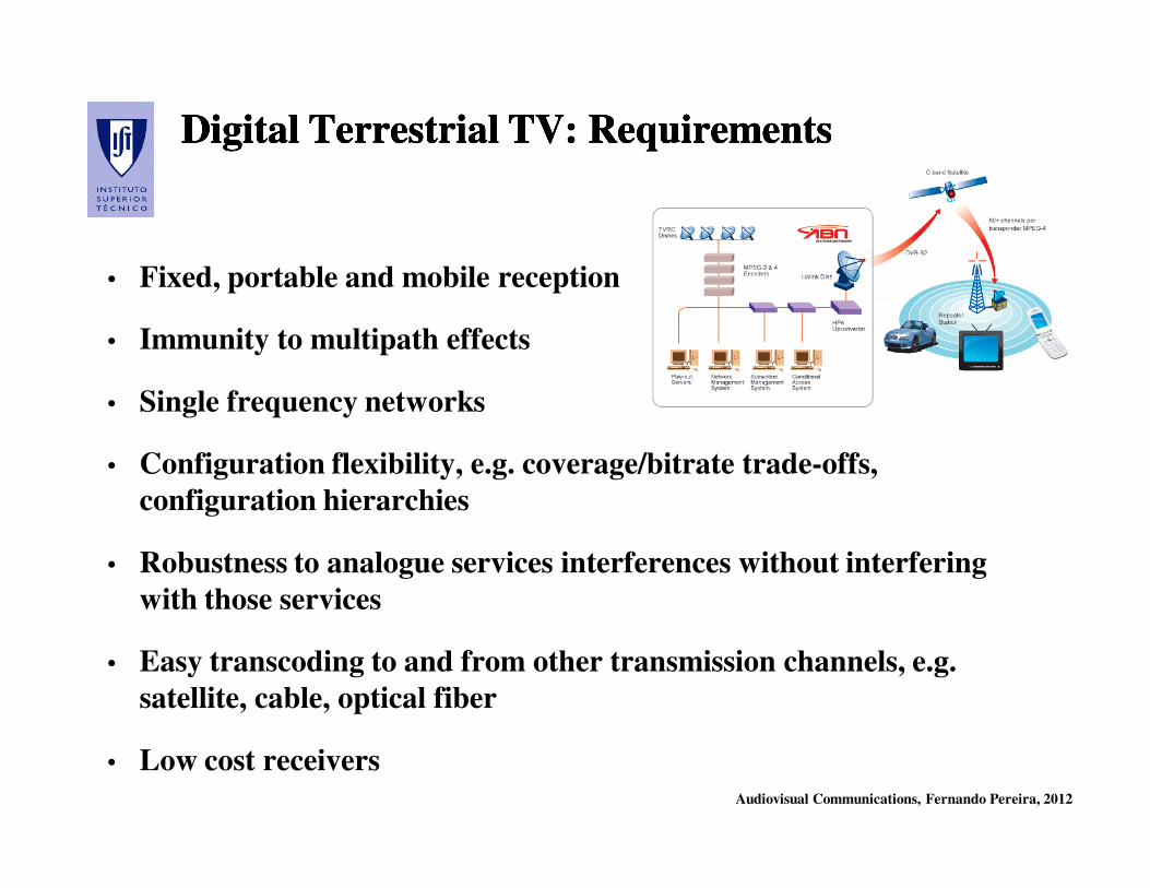
Digital Terrestrial TV: RequirementsDigital Terrestrial TV: RequirementsDigital Terrestrial TV: RequirementsDigital Terrestrial TV: Requirements
• Fixed, portable and mobile reception
• Immunity to multipath effects
• Single frequency networks
• Configuration flexibility, e.g. coverage/bitrate trade-offs,
configuration hierarchies
• Robustness to analogue services interferences without interfering
with those services
• Easy transcoding to and from other transmission channels, e.g.
satellite, cable, optical fiber
• Low cost receivers
Audiovisual Communications, Fernando Pereira, 2012
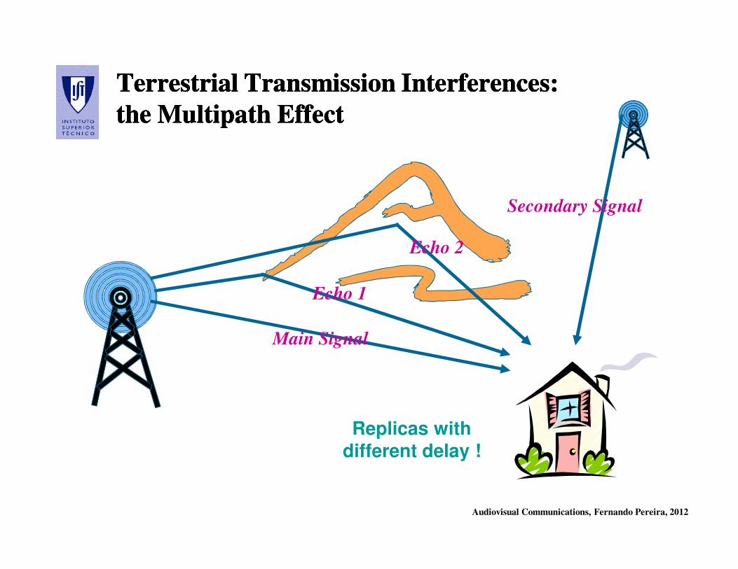
Terrestrial Transmission Interferences:Terrestrial Transmission Interferences:
the Multipath Effect the Multipath Effect
Terrestrial Transmission Interferences:Terrestrial Transmission Interferences:
the Multipath Effect the Multipath Effect
Main Signal
Echo 1
Echo 2
Secondary Signal
Replicas with
different delay !

Audiovisual Communications, Fernando Pereira, 2012
Single Frequency NetworksSingle Frequency NetworksSingle Frequency NetworksSingle Frequency Networks
• In analogue reception, the user tunes the
best ‘behaving’ frequency for a certain
TV channel (from different emitters),
notably by pointing the antenna in the
right direction.
• In digital SFN, all transmitters within
some area can transmit the same TV
channel on the same frequency.
• It is important not only to ‘filter’ the
signals from the other transmitters using
an antenna with an adequate radiation
diagram and, naturally, but also to deal
with the associated multipath delays.
• This kind of operation - Single
Frequency Network (SFN) - significantly
contributes to the efficient use of the
radio frequency spectrum.
Audiovisual Communications, Fernando Pereira, 2012
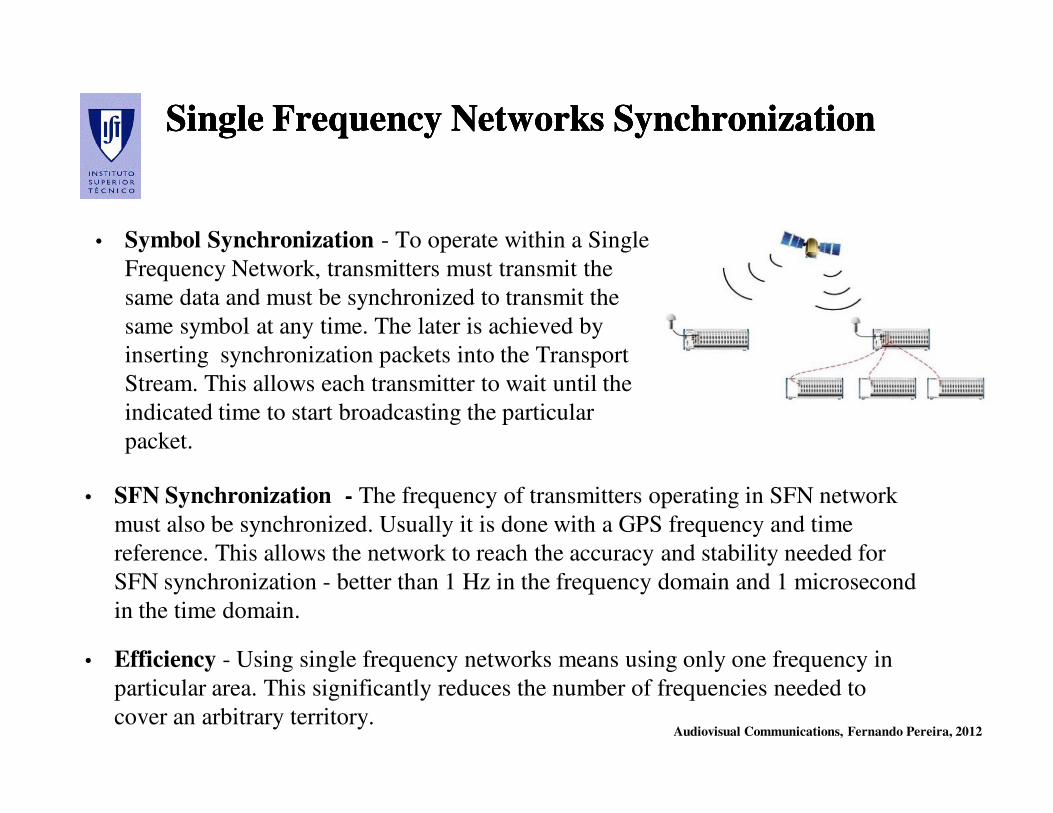
Single Frequency Networks SynchronizationSingle Frequency Networks SynchronizationSingle Frequency Networks SynchronizationSingle Frequency Networks Synchronization
• SFN Synchronization - The frequency of transmitters operating in SFN network
must also be synchronized. Usually it is done with a GPS frequency and time
reference. This allows the network to reach the accuracy and stability needed for
SFN synchronization - better than 1 Hz in the frequency domain and 1 microsecond
in the time domain.
• Efficiency - Using single frequency networks means using only one frequency in
particular area. This significantly reduces the number of frequencies needed to
cover an arbitrary territory.
• Symbol Synchronization - To operate within a Single
Frequency Network, transmitters must transmit the
same data and must be synchronized to transmit the
same symbol at any time. The later is achieved by
inserting synchronization packets into the Transport
Stream. This allows each transmitter to wait until the
indicated time to start broadcasting the particular
packet.
Audiovisual Communications, Fernando Pereira, 2012
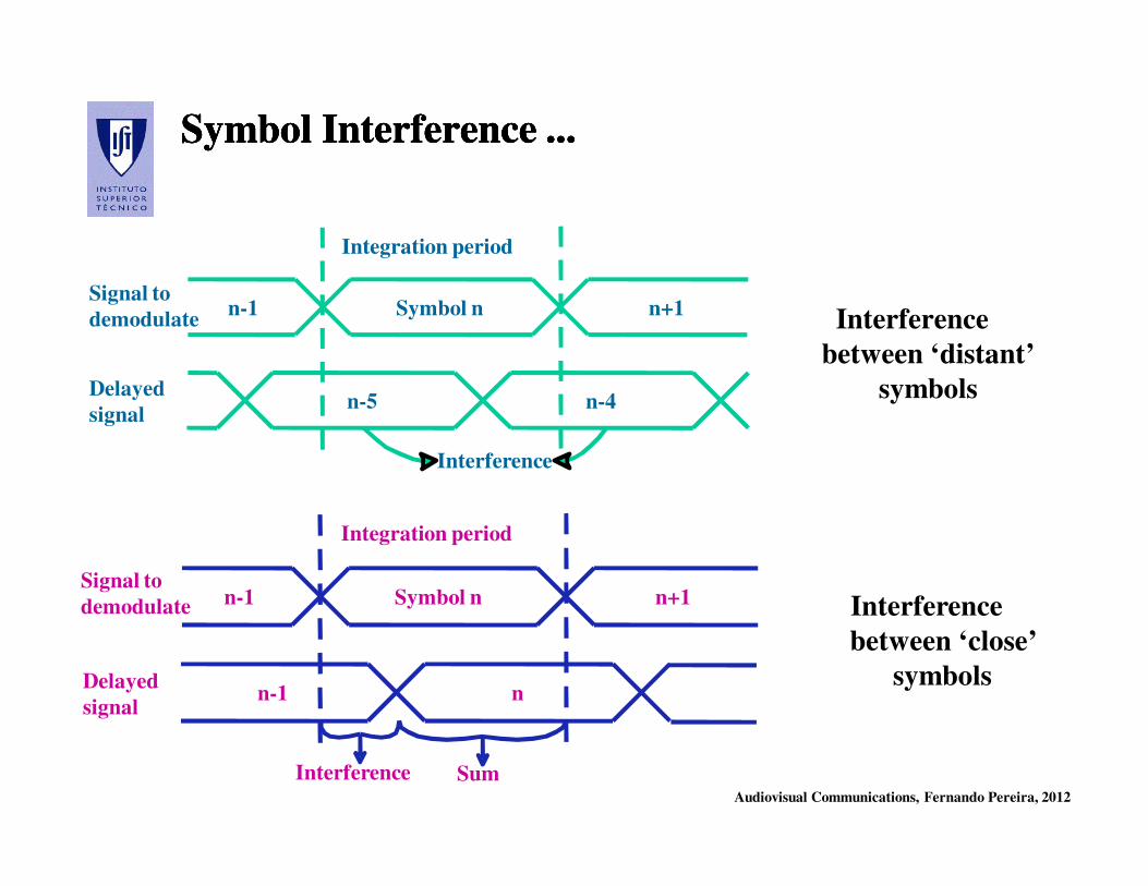
Symbol Interference ...Symbol Interference ...Symbol Interference ...Symbol Interference ...
n-1 Symbol n n+1
n-1 n
Interference
Integration period
Signal to
demodulate
Delayed
signal
Sum
n-1 Symbol n n+1
n-5 n-4
Interference
Integration period
Signal to
demodulate
Delayed
signal
Interference
between ‘distant’
symbols
Interference
between ‘close’
symbols
Audiovisual Communications, Fernando Pereira, 2012
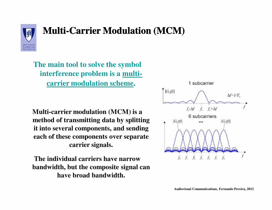
MultiMulti--Carrier Modulation (MCM) Carrier Modulation (MCM) MultiMulti--Carrier Modulation (MCM) Carrier Modulation (MCM)
The main tool to solve the symbol
interference problem is a multi-
carrier modulation scheme.
Multi-carrier modulation (MCM) is a
method of transmitting data by splitting
it into several components, and sending
each of these components over separate
carrier signals.
The individual carriers have narrow
bandwidth, but the composite signal can
have broad bandwidth.
Audiovisual Communications, Fernando Pereira, 2012
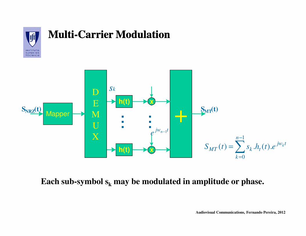
MultiMulti--Carrier ModulationCarrier ModulationMultiMulti--Carrier ModulationCarrier Modulation
Each sub-symbol sk may be modulated in amplitude or phase.
∑−
=
=
1
0
).(.)(
n
k
tjwtkMT
kethstS
+xh(t)
xh(t)
D
E
M
U
X
Mapper ...
...
SNRZ(t) SMT(t)
ks
tjwne 1−
Audiovisual Communications, Fernando Pereira, 2012
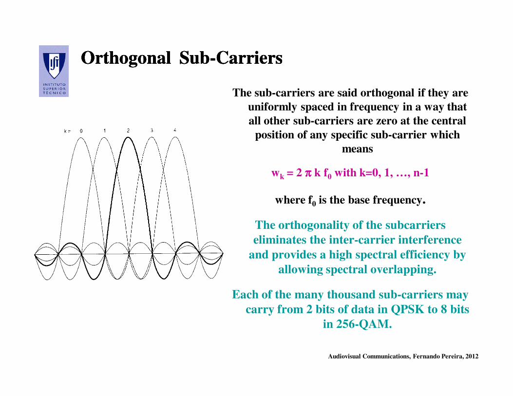
Orthogonal SubOrthogonal Sub--CarriersCarriersOrthogonal SubOrthogonal Sub--CarriersCarriers
The sub-carriers are said orthogonal if they are
uniformly spaced in frequency in a way that
all other sub-carriers are zero at the central
position of any specific sub-carrier which
means
wk = 2 ππππ k f0 with k=0, 1, …, n-1
where f0 is the base frequency.
The orthogonality of the subcarriers
eliminates the inter-carrier interference
and provides a high spectral efficiency by
allowing spectral overlapping.
Each of the many thousand sub-carriers may
carry from 2 bits of data in QPSK to 8 bits
in 256-QAM.
Audiovisual Communications, Fernando Pereira, 2012
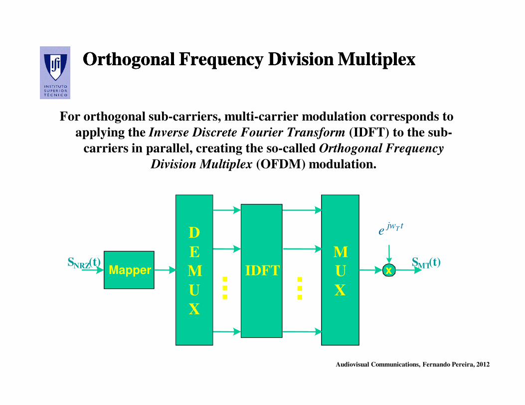
Orthogonal Frequency Division Multiplex Orthogonal Frequency Division Multiplex Orthogonal Frequency Division Multiplex Orthogonal Frequency Division Multiplex
For orthogonal sub-carriers, multi-carrier modulation corresponds to
applying the Inverse Discrete Fourier Transform (IDFT) to the sub-
carriers in parallel, creating the so-called Orthogonal Frequency
Division Multiplex (OFDM) modulation.
M
U
X
D
E
M
U
X
MapperSNRZ(t) SMT(t)
IDFT ...
...x
tjwTe
Audiovisual Communications, Fernando Pereira, 2012
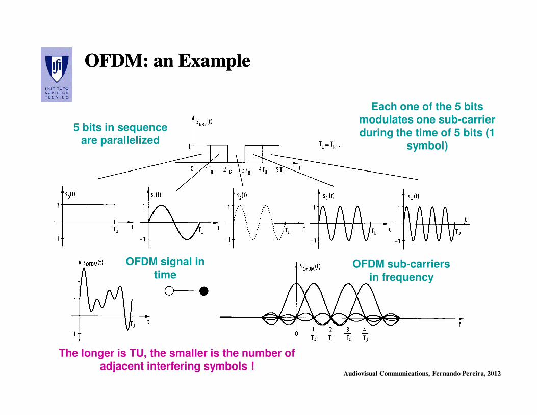
OFDM: an ExampleOFDM: an ExampleOFDM: an ExampleOFDM: an Example
5 bits in sequence are parallelized
Each one of the 5 bits modulates one sub-carrier during the time of 5 bits (1
symbol)
OFDM signal in time
OFDM sub-carriers in frequency
The longer is TU, the smaller is the number of adjacent interfering symbols !
Audiovisual Communications, Fernando Pereira, 2012
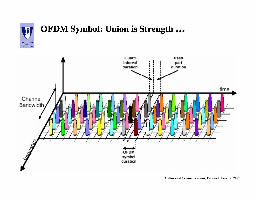
OFDM Symbol: Union is Strength …OFDM Symbol: Union is Strength …OFDM Symbol: Union is Strength …OFDM Symbol: Union is Strength …
Audiovisual Communications, Fernando Pereira, 2012
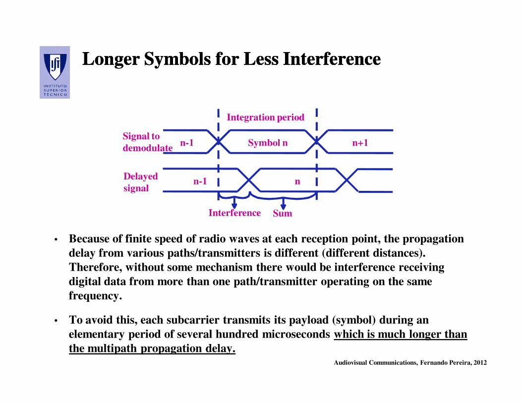
Longer Symbols for Less InterferenceLonger Symbols for Less InterferenceLonger Symbols for Less InterferenceLonger Symbols for Less Interference
• Because of finite speed of radio waves at each reception point, the propagation
delay from various paths/transmitters is different (different distances).
Therefore, without some mechanism there would be interference receiving
digital data from more than one path/transmitter operating on the same
frequency.
• To avoid this, each subcarrier transmits its payload (symbol) during an
elementary period of several hundred microseconds which is much longer than
the multipath propagation delay.
n-1 Symbol n n+1
n-1 n
Interference
Integration period
Signal to
demodulate
Delayed
signal
Sum

Audiovisual Communications, Fernando Pereira, 2012
Guard Interval for an Interference Free Guard Interval for an Interference Free
ZoneZone
Guard Interval for an Interference Free Guard Interval for an Interference Free
ZoneZone
• The adoption of a guard interval allows creating a time zone free of
interferences between different modulated symbols received through
multiple paths.
• The length of the guard interval must be longer than the largest delay
corresponding to the interfering signals (and this depends on the diffusion
cells, notably their size).
Guard Guard
iintervalnterval
TTGG
Time for demodulationTime for demodulation
TTSS
TTUU
Audiovisual Communications, Fernando Pereira, 2012
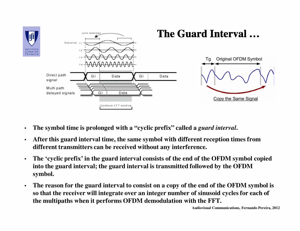
• The symbol time is prolonged with a “cyclic prefix” called a guard interval.
• After this guard interval time, the same symbol with different reception times from
different transmitters can be received without any interference.
• The ‘cyclic prefix’ in the guard interval consists of the end of the OFDM symbol copied
into the guard interval; the guard interval is transmitted followed by the OFDM
symbol.
• The reason for the guard interval to consist on a copy of the end of the OFDM symbol is
so that the receiver will integrate over an integer number of sinusoid cycles for each of
the multipaths when it performs OFDM demodulation with the FFT.
The Guard Interval …The Guard Interval …The Guard Interval …The Guard Interval …

Audiovisual Communications, Fernando Pereira, 2012
Example: Absorbing Delay with a Guard IntervalExample: Absorbing Delay with a Guard IntervalExample: Absorbing Delay with a Guard IntervalExample: Absorbing Delay with a Guard Interval
1. SINGLE-CARRIER MODULATION CASE
• If 1 Msymbol/s are to be sent, then the duration of each symbol would be 1 µs or less.
- This imposes severe constraints on synchronization and necessitates the removal of
multipath interference.
2. MULTI-CARRIER MODULATION CASE
• If the same 1 Msymbol/s are spread among 1000 sub-channels, the duration of each
symbol can be longer by a factor of 1000 (i.e., 1 ms) with approximately the same
bandwidth.
• If a guard interval of 1/8 of the symbol length is
inserted between each symbol (with 1 ms),
intersymbol interference can be avoided if the
multipath time-spreading (the time between the
reception of the first and the last echo) is shorter than
the guard interval, i.e. 125 µs).
• This corresponds to a maximum difference of 37.5 km
between the lengths of the paths.
Audiovisual Communications, Fernando Pereira, 2012
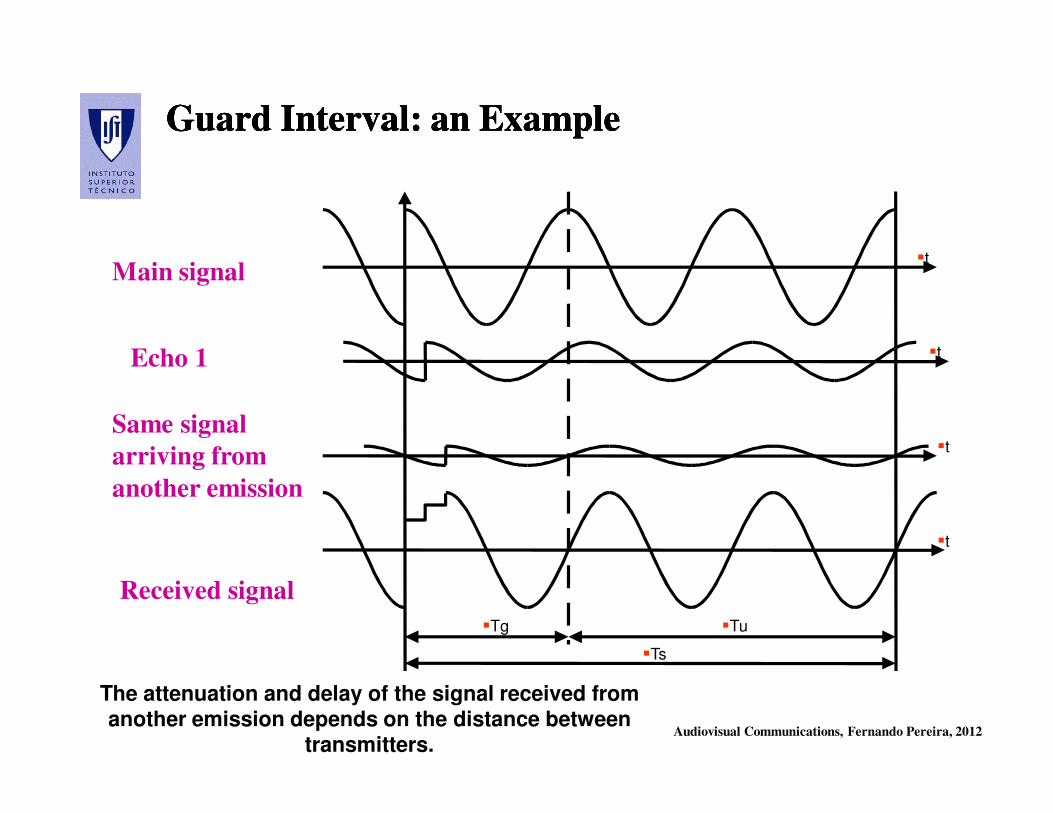
Guard Interval: an ExampleGuard Interval: an ExampleGuard Interval: an ExampleGuard Interval: an Example
Main signal
Echo 1
Same signal
arriving from
another emission
Received signal
�Tg �Tu
�Ts
�t
�t
�t
�t
The attenuation and delay of the signal received from another emission depends on the distance between
transmitters.
Audiovisual Communications, Fernando Pereira, 2012
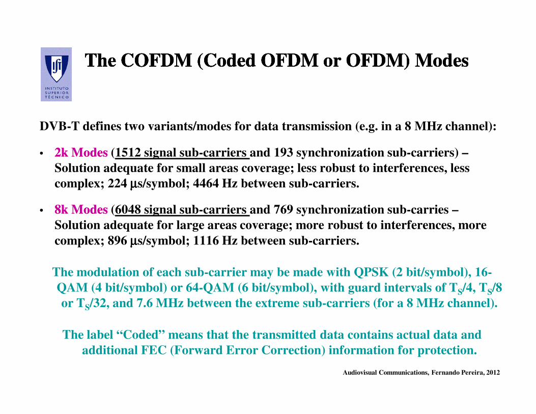
The COFDM (Coded OFDM or OFDM) ModesThe COFDM (Coded OFDM or OFDM) ModesThe COFDM (Coded OFDM or OFDM) ModesThe COFDM (Coded OFDM or OFDM) Modes
DVB-T defines two variants/modes for data transmission (e.g. in a 8 MHz channel):
•• 2k Modes2k Modes (1512 signal sub-carriers and 193 synchronization sub-carriers) –
Solution adequate for small areas coverage; less robust to interferences, less
complex; 224 µµµµs/symbol; 4464 Hz between sub-carriers.
•• 8k Modes8k Modes (6048 signal sub-carriers and 769 synchronization sub-carries –
Solution adequate for large areas coverage; more robust to interferences, more
complex; 896 µµµµs/symbol; 1116 Hz between sub-carriers.
The modulation of each sub-carrier may be made with QPSK (2 bit/symbol), 16-
QAM (4 bit/symbol) or 64-QAM (6 bit/symbol), with guard intervals of TS/4, TS/8
or TS/32, and 7.6 MHz between the extreme sub-carriers (for a 8 MHz channel).
The label “Coded” means that the transmitted data contains actual data and
additional FEC (Forward Error Correction) information for protection.
Audiovisual Communications, Fernando Pereira, 2012
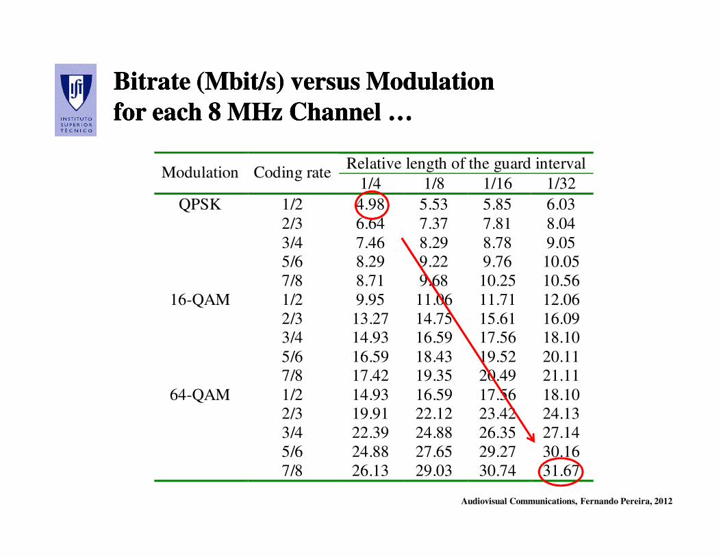
Bitrate Bitrate (Mbit/s) (Mbit/s) versus Modulation versus Modulation
for each 8 MHz Channel …for each 8 MHz Channel …
Bitrate Bitrate (Mbit/s) (Mbit/s) versus Modulation versus Modulation
for each 8 MHz Channel …for each 8 MHz Channel …
Relative length of the guard interval Modulation Coding rate
1/4 1/8 1/16 1/32
QPSK 1/2 4.98 5.53 5.85 6.03
2/3 6.64 7.37 7.81 8.04
3/4 7.46 8.29 8.78 9.05
5/6 8.29 9.22 9.76 10.05
7/8 8.71 9.68 10.25 10.56
16-QAM 1/2 9.95 11.06 11.71 12.06
2/3 13.27 14.75 15.61 16.09
3/4 14.93 16.59 17.56 18.10
5/6 16.59 18.43 19.52 20.11
7/8 17.42 19.35 20.49 21.11
64-QAM 1/2 14.93 16.59 17.56 18.10
2/3 19.91 22.12 23.42 24.13
3/4 22.39 24.88 26.35 27.14
5/6 24.88 27.65 29.27 30.16
7/8 26.13 29.03 30.74 31.67
Audiovisual Communications, Fernando Pereira, 2012
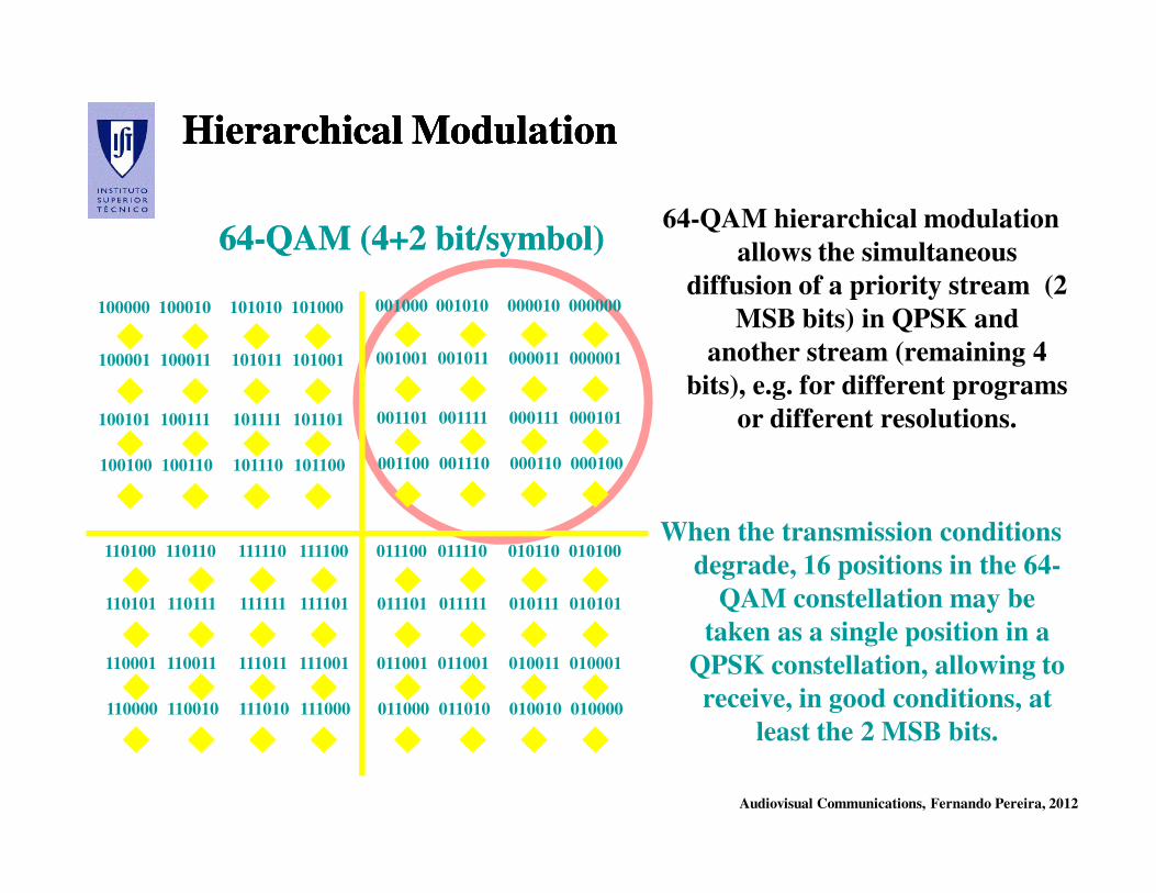
Hierarchical ModulationHierarchical ModulationHierarchical ModulationHierarchical Modulation
64-QAM hierarchical modulation
allows the simultaneous
diffusion of a priority stream (2
MSB bits) in QPSK and
another stream (remaining 4
bits), e.g. for different programs
or different resolutions.
When the transmission conditions
degrade, 16 positions in the 64-
QAM constellation may be
taken as a single position in a
QPSK constellation, allowing to
receive, in good conditions, at
least the 2 MSB bits.
6464--QAM (4+2 bit/symbol)QAM (4+2 bit/symbol)
100000 101000101010100010
100001 101001101011100011
100101 101101101111100111
100100 101100101110100110
001000 000000000010001010
001001 000001000011001011
001101 000101000111001111
001100 000100000110001110
011100 010100010110011110
011101 010101010111011111
011001 010001010011011001
011000 010000010010011010
110100 111100111110110110
110101 111101111111110111
110001 111001111011110011
110000 111000111010110010
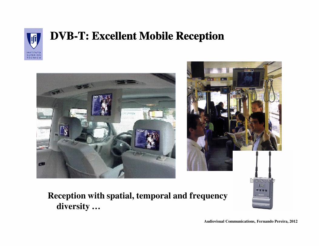
Audiovisual Communications, Fernando Pereira, 2012
DVBDVB--T: Excellent Mobile ReceptionT: Excellent Mobile ReceptionDVBDVB--T: Excellent Mobile ReceptionT: Excellent Mobile Reception
Reception with spatial, temporal and frequency
diversity …
Audiovisual Communications, Fernando Pereira, 2012
Main DVBMain DVB--T Technical CharacteristicsT Technical CharacteristicsMain DVBMain DVB--T Technical CharacteristicsT Technical Characteristics
• Many characteristics common to the DVB-S and DVB-C systems
• Inclusion of the convolutional channel coding from DVB-S
• OFDM modulation based on QPSK and QAM (very robust to
multipath effects) with 2k and 8k OFDM modes
• Two hierarchical layers of channel coding and modulation
• MPEG-2 Video (Main profile) and later H.264/AVC source coding
• Definition of national and regional broadcasting networks (Single
Frequency Networks (SFN) and Multiple Frequency Networks
(MFN))
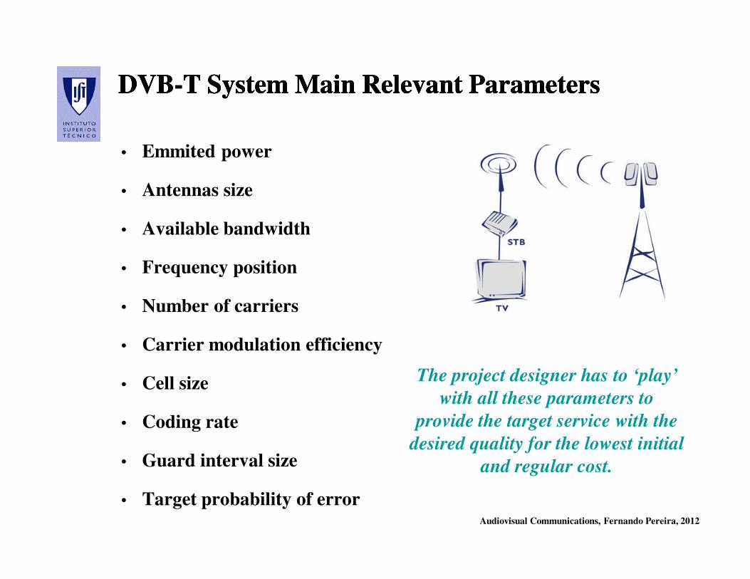
Audiovisual Communications, Fernando Pereira, 2012
DVBDVB--T T SystemSystem MainMain RelevantRelevant ParametersParametersDVBDVB--T T SystemSystem MainMain RelevantRelevant ParametersParameters
• Emmited power
• Antennas size
• Available bandwidth
• Frequency position
• Number of carriers
• Carrier modulation efficiency
• Cell size
• Coding rate
• Guard interval size
• Target probability of error
The project designer has to ‘play’
with all these parameters to
provide the target service with the
desired quality for the lowest initial
and regular cost.

Audiovisual Communications, Fernando Pereira, 2012
DVBDVB--x2: x2:
The Second GenerationThe Second Generation
2005 2008 2008
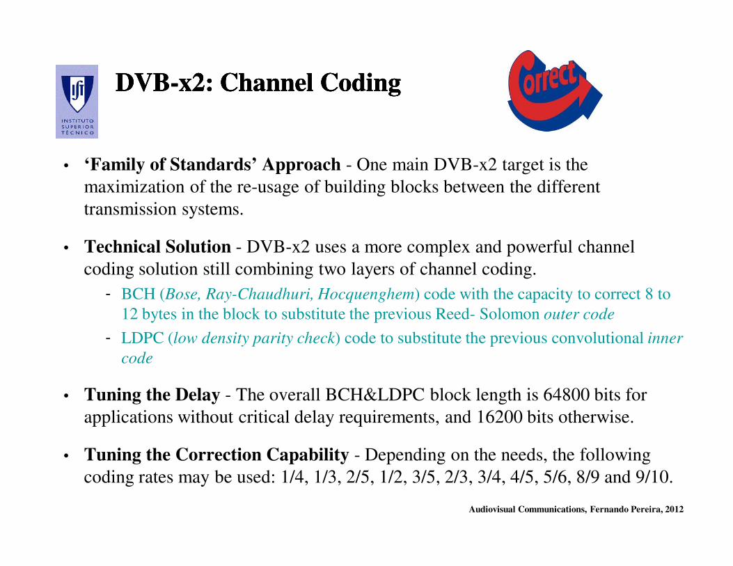
Audiovisual Communications, Fernando Pereira, 2012
DVBDVB--x2: Channel Codingx2: Channel CodingDVBDVB--x2: Channel Codingx2: Channel Coding
• ‘Family of Standards’ Approach - One main DVB-x2 target is the
maximization of the re-usage of building blocks between the different
transmission systems.
• Technical Solution - DVB-x2 uses a more complex and powerful channel
coding solution still combining two layers of channel coding.
- BCH (Bose, Ray-Chaudhuri, Hocquenghem) code with the capacity to correct 8 to
12 bytes in the block to substitute the previous Reed- Solomon outer code
- LDPC (low density parity check) code to substitute the previous convolutional inner
code
• Tuning the Delay - The overall BCH&LDPC block length is 64800 bits for
applications without critical delay requirements, and 16200 bits otherwise.
• Tuning the Correction Capability - Depending on the needs, the following
coding rates may be used: 1/4, 1/3, 2/5, 1/2, 3/5, 2/3, 3/4, 4/5, 5/6, 8/9 and 9/10.
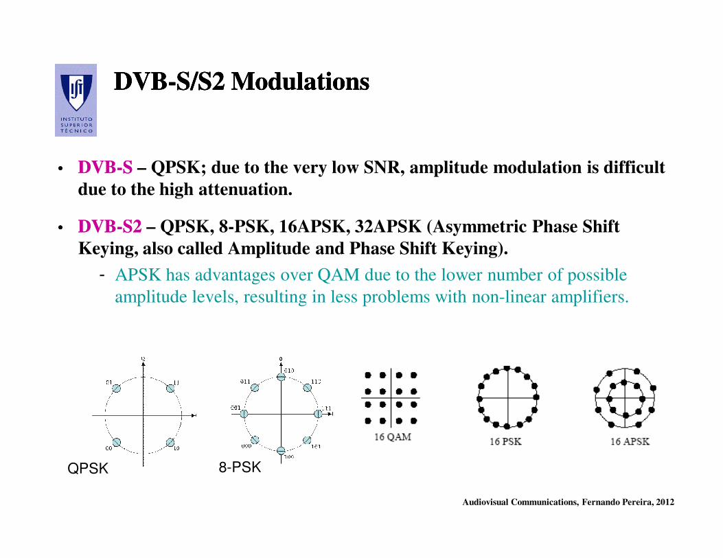
Audiovisual Communications, Fernando Pereira, 2012
DVBDVB--S/S2 ModulationsS/S2 ModulationsDVBDVB--S/S2 ModulationsS/S2 Modulations
•• DVBDVB--S S – QPSK; due to the very low SNR, amplitude modulation is difficult
due to the high attenuation.
•• DVBDVB--S2S2 – QPSK, 8-PSK, 16APSK, 32APSK (Asymmetric Phase Shift
Keying, also called Amplitude and Phase Shift Keying).
- APSK has advantages over QAM due to the lower number of possible
amplitude levels, resulting in less problems with non-linear amplifiers.
QPSK 8-PSK
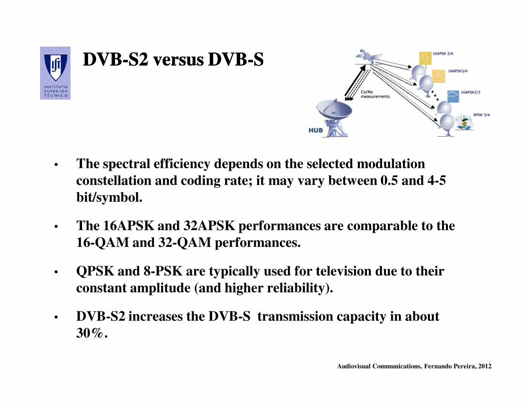
Audiovisual Communications, Fernando Pereira, 2012
DVBDVB--S2 versus DVBS2 versus DVB--SSDVBDVB--S2 versus DVBS2 versus DVB--SS
• The spectral efficiency depends on the selected modulation
constellation and coding rate; it may vary between 0.5 and 4-5
bit/symbol.
• The 16APSK and 32APSK performances are comparable to the
16-QAM and 32-QAM performances.
• QPSK and 8-PSK are typically used for television due to their
constant amplitude (and higher reliability).
• DVB-S2 increases the DVB-S transmission capacity in about
30%.
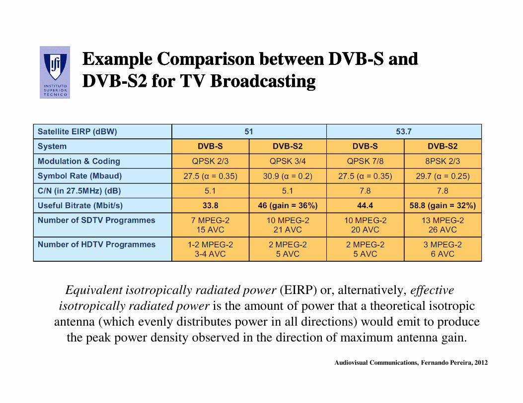
Audiovisual Communications, Fernando Pereira, 2012
Example Comparison between DVBExample Comparison between DVB--S and S and
DVBDVB--S2 for TV BroadcastingS2 for TV Broadcasting
Example Comparison between DVBExample Comparison between DVB--S and S and
DVBDVB--S2 for TV BroadcastingS2 for TV Broadcasting
Equivalent isotropically radiated power (EIRP) or, alternatively, effective
isotropically radiated power is the amount of power that a theoretical isotropic
antenna (which evenly distributes power in all directions) would emit to produce
the peak power density observed in the direction of maximum antenna gain.

Audiovisual Communications, Fernando Pereira, 2012
DVBDVB--C/C2 ModulationsC/C2 ModulationsDVBDVB--C/C2 ModulationsC/C2 Modulations
•• DVBDVB--CC – Single carrier, 16 to 256-QAM, typically 64-QAM.
•• DVBDVB--C2 C2 - Orthogonal Frequency Division Multiplex (OFDM) based on QAM
modulation; this allows for the cost effective implementation of common DVB-
T2/C2 receiver chipsets.
• DVB-C2 provides increased spectral efficiency by means of the LDPC codes in
addition with higher QAM mappings and OFDM.
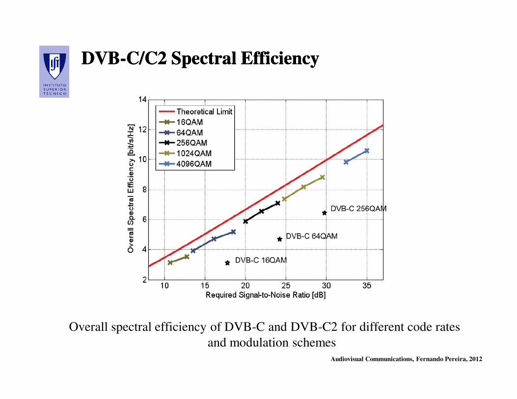
Audiovisual Communications, Fernando Pereira, 2012
DVBDVB--C/C2 Spectral EfficiencyC/C2 Spectral EfficiencyDVBDVB--C/C2 Spectral EfficiencyC/C2 Spectral Efficiency
Overall spectral efficiency of DVB-C and DVB-C2 for different code rates
and modulation schemes
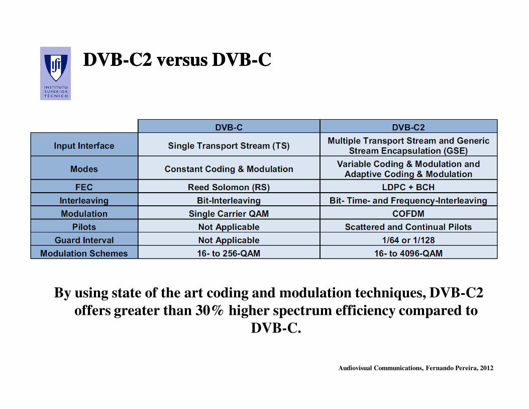
Audiovisual Communications, Fernando Pereira, 2012
DVBDVB--C2 versus DVBC2 versus DVB--CCDVBDVB--C2 versus DVBC2 versus DVB--CC
By using state of the art coding and modulation techniques, DVB-C2
offers greater than 30% higher spectrum efficiency compared to
DVB-C.
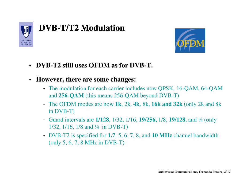
Audiovisual Communications, Fernando Pereira, 2012
DVBDVB--T/T2 ModulationT/T2 ModulationDVBDVB--T/T2 ModulationT/T2 Modulation
• DVB-T2 still uses OFDM as for DVB-T.
• However, there are some changes:
- The modulation for each carrier includes now QPSK, 16-QAM, 64-QAM
and 256-QAM (this means 256-QAM beyond DVB-T)
- The OFDM modes are now 1k, 2k, 4k, 8k, 16k and 32k (only 2k and 8k
in DVB-T)
- Guard intervals are 1/128, 1/32, 1/16, 19/256, 1/8, 19/128, and ¼ (only
1/32, 1/16, 1/8 and ¼ in DVB-T)
- DVB-T2 is specified for 1.7, 5, 6, 7, 8, and 10 MHz channel bandwidth
(only 5, 6, 7, 8 MHz in DVB-T)

Audiovisual Communications, Fernando Pereira, 2012
DVBDVB--T versus DVBT versus DVB--T2T2DVBDVB--T versus DVBT versus DVB--T2T2
DVB-T2 can offer a much higher rate than DVB-T or a much more robust
signal.
For comparison, the last two rows show the maximum rate at a fixed C/N and the
required C/N for a fixed (useful) rate.
Audiovisual Communications, Fernando Pereira, 2012
DVBDVB--T T
DeploymentDeployment
20081997
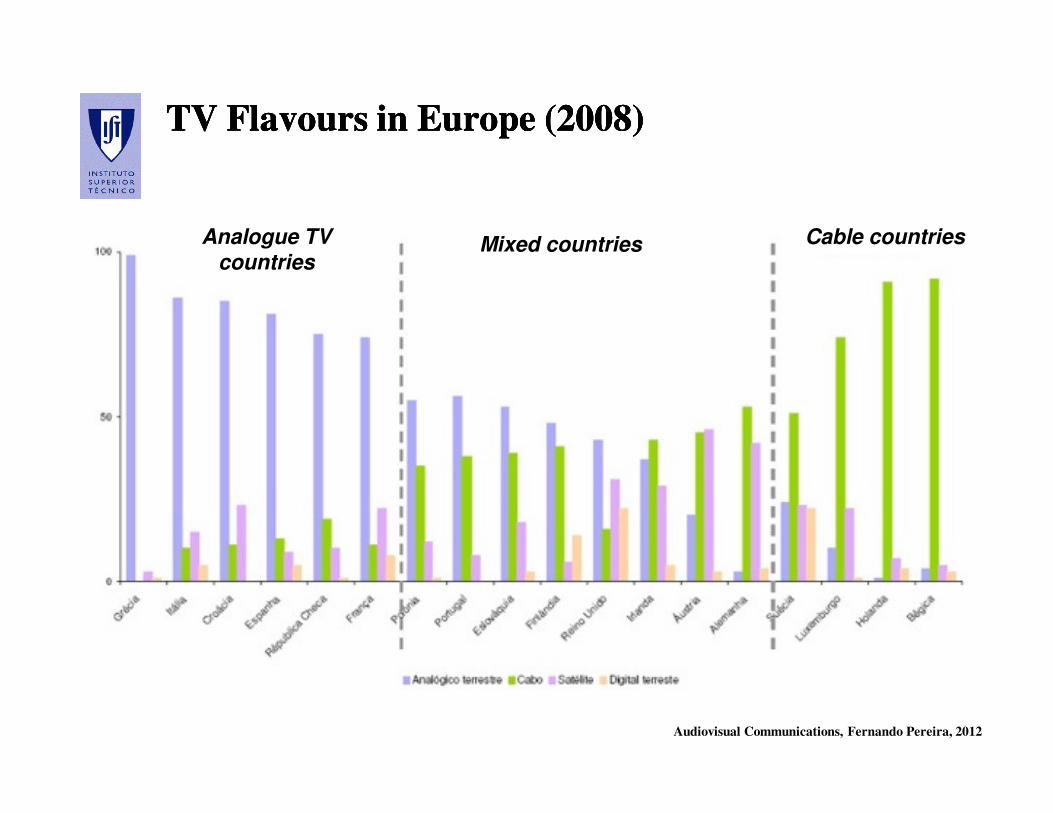
Audiovisual Communications, Fernando Pereira, 2012
TV Flavours in Europe (2008)TV Flavours in Europe (2008)TV Flavours in Europe (2008)TV Flavours in Europe (2008)
Cable countriesMixed countriesAnalogue TV countries
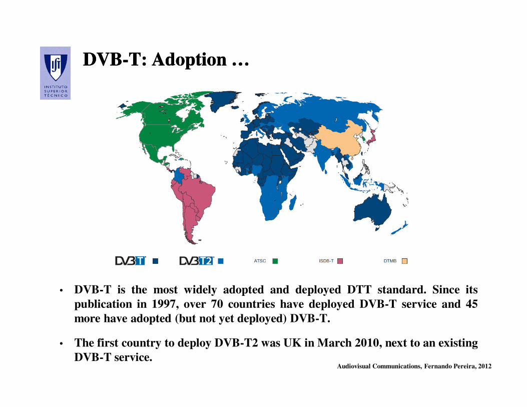
Audiovisual Communications, Fernando Pereira, 2012
DVBDVB--T: Adoption …T: Adoption …DVBDVB--T: Adoption …T: Adoption …
• DVB-T is the most widely adopted and deployed DTT standard. Since its
publication in 1997, over 70 countries have deployed DVB-T service and 45
more have adopted (but not yet deployed) DVB-T.
• The first country to deploy DVB-T2 was UK in March 2010, next to an existing
DVB-T service.
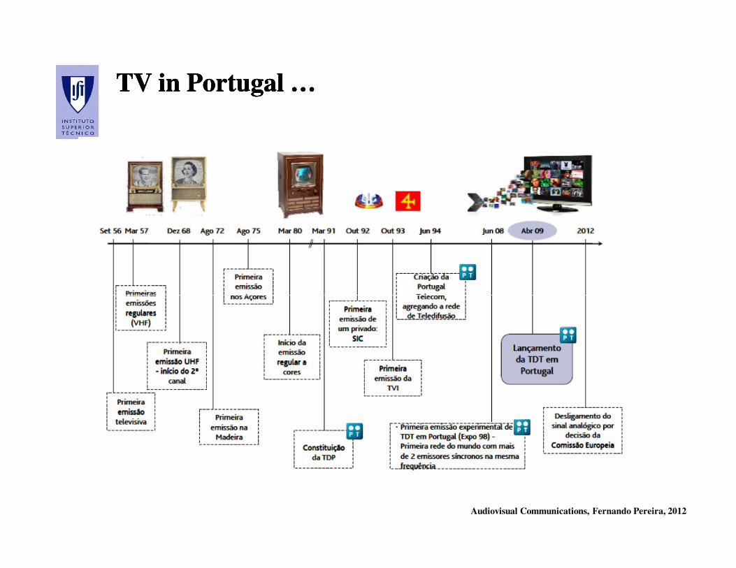
Audiovisual Communications, Fernando Pereira, 2012
TV in Portugal …TV in Portugal …TV in Portugal …TV in Portugal …
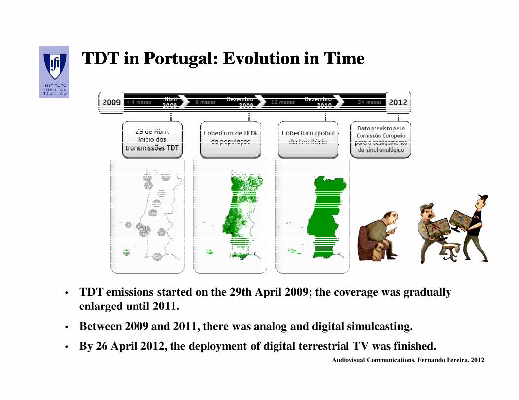
Audiovisual Communications, Fernando Pereira, 2012
TDT in Portugal: Evolution in TimeTDT in Portugal: Evolution in TimeTDT in Portugal: Evolution in TimeTDT in Portugal: Evolution in Time
• TDT emissions started on the 29th April 2009; the coverage was gradually
enlarged until 2011.
• Between 2009 and 2011, there was analog and digital simulcasting.
• By 26 April 2012, the deployment of digital terrestrial TV was finished.

Audiovisual Communications, Fernando Pereira, 2012
TDT in PortugalTDT in PortugalTDT in PortugalTDT in Portugal
• TDT in Portugal will use 6 multiplexers (A, B, C, D, E e F) and Single
Frequency Networks (SFN).
• Multiplexer A will transmit the free channels already with license
(RTP 1, RTP 2, SIC e TVI); the fifth channel was intended for this
multiplexer but plans for it were withdrawn.
• Multiplexers B to F should be for ‘pay TV’ (no current plans to
deploy).
• Multiplexers B and C are national and Multiplexers D, E, F have
partial coverage with a save zone of 80 km from the border with Spain
(meaning that part of the population will not see these channels).
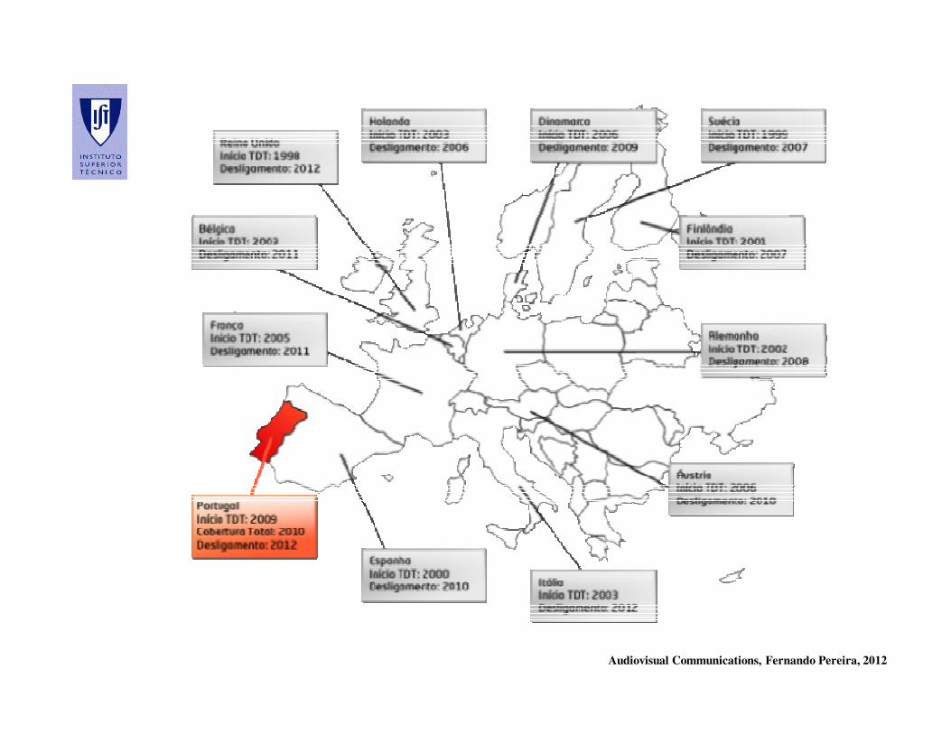
Audiovisual Communications, Fernando Pereira, 2012
Audiovisual Communications, Fernando Pereira, 2012
Conditional AccessConditional Access
Audiovisual Communications, Fernando Pereira, 2012
Conditional Access (CA)Conditional Access (CA)Conditional Access (CA)Conditional Access (CA)
• Conditional access, and thus the possibility to get payment for service, is essential
for the launcing of digital TV and the deployment of different business models,
e.g. monthly subscription, Pay Per View (PPV), Near Video on Demand (VOD).
• The primary purpose of a CA system for broadcasting is to determine which
individual receivers/ set-top box decoders shall be able to deliver particular
programme services, or individual programs, to the viewers.
• The reasons why access may need to be restricted include:
- To enforce payments by viewers who want access to particular programs or services;
- To restrict access to a particular geographical area because of programme-rights
considerations (territorial control can be enforced if the receiver has a GPS system);
- To facilitate parental control (i.e. to restrict access to certain categories of programme).
• The CA system filters the user access to a service or program by verifying certain
requirements, e.g. identification, authentication, authorization, registering, and
payment.
Audiovisual Communications, Fernando Pereira, 2012
Business Models …Business Models …Business Models …Business Models …
A business model is a framework for creating economic, social,
and/or other forms of value. The term business model is used for a broad
range of informal and formal descriptions to represent core aspects of a
business, including purpose, offerings, strategies, infrastructures, trading
practices, and operational processes and policies.
• Period Subscription - The most popular payment system, in which the viewer
subscribes to a programme service for a calendar period (e.g. one month).
• Pay-Per-View (PPV) - A payment system whereby the viewer can pay for individual
programs rather than take out a period subscription. Pay-Per-View can work by debiting
the electronic credit stored in a smart card, by purchasing smart cards issued for special
programs, or by electronic banking using a telephone line to carry debiting information
from the home to the bank.
• Impulse Pay-Per-View - Impulse Pay-Per-View requires no pre-booking. This rules
out some Pay-Per-View methods, e.g. issuing smart cards for specific programs. Smart
card debit or electronic banking via telephone line, both support impulse Pay-Per-View.

Audiovisual Communications, Fernando Pereira, 2012
Conditional Access ComponentsConditional Access ComponentsConditional Access ComponentsConditional Access Components
To avoid non-authorized users accessing a certain program or service, a CA
system involves a combination of:
• Scrambling – The method of continually changing the form of the broadcast
signal so that, without a suitable decoder and electronic key, the signal is
unintelligible.
• Encryption – The method of processing the continually changing electronic keys
needed to descramble the broadcast signals, so that they can be securely conveyed
to the authorized users, either over-the-air or on smart cards.
• Subscriber Management System – The business centre which issues the smart
cards, sends out bills and receives payments from subscribers. An important
resource of the Subscriber Management System is a database of information
about the subscribers, the serial numbers of the decoders and information about
the services to which they have subscribed. In commercial terms, this information
is highly sensitive.
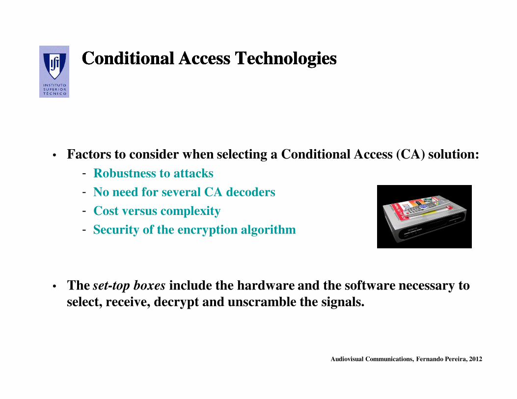
Audiovisual Communications, Fernando Pereira, 2012
Conditional Access TechnologiesConditional Access TechnologiesConditional Access TechnologiesConditional Access Technologies
• Factors to consider when selecting a Conditional Access (CA) solution:
- Robustness to attacks
- No need for several CA decoders
- Cost versus complexity
- Security of the encryption algorithm
• The set-top boxes include the hardware and the software necessary to
select, receive, decrypt and unscramble the signals.
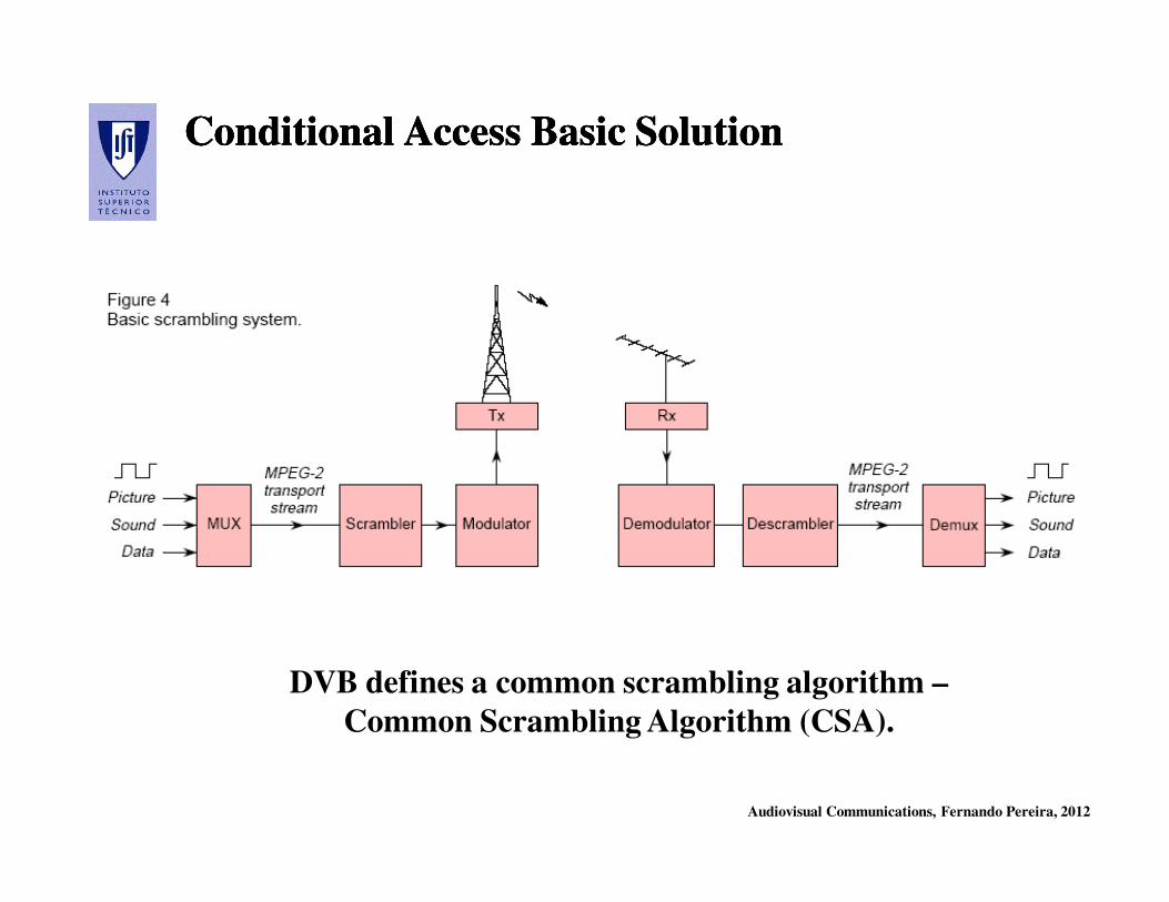
Audiovisual Communications, Fernando Pereira, 2012
Conditional Access Basic SolutionConditional Access Basic SolutionConditional Access Basic SolutionConditional Access Basic Solution
DVB defines a common scrambling algorithm –
Common Scrambling Algorithm (CSA).

Audiovisual Communications, Fernando Pereira, 2012
• EMM –
Encrypted key
which ‘authorizes’
the descrambling
process to the
users equipped
for that.
• ECM – Encrypted
key which allows
descrambling the
signal (together
with the service
key resulting from
the EMM); it is
updated every 2-
10 s.• ECM – Entitlement Control Message
• EMM – Entitlement Management Message
Smart card

Audiovisual Communications, Fernando Pereira, 2012
DVB DVB CommonCommon
Interface (DVBInterface (DVB--
CI)CI) betweenbetween thethe
integratedintegrated
receiverreceiver--decoderdecoder
(IRD) (IRD) andand thethe
CA CA systemsystem
Note: this interface
is not crossed by any
secret data and the
CA system may be
any.
DVB DVB CommonCommon
Interface (DVBInterface (DVB--
CI)CI) betweenbetween thethe
integratedintegrated
receiverreceiver--decoderdecoder
(IRD) (IRD) andand thethe
CA CA systemsystem
Note: this interface
is not crossed by any
secret data and the
CA system may be
any.
Audiovisual Communications, Fernando Pereira, 2012
DVB Conditional AccessDVB Conditional AccessDVB Conditional AccessDVB Conditional Access
• The CA system is not fully specified by DVB leaving to the operators the
selection of the technologies for some modules.
• Conditional access data is transmitted through the MPEG-2 Transport
Stream CAT and the private data packets identified by the PMT.
• DVB defines a common scrambling algorithm – Common Scrambling
Algorithm (CSA).
• To avoid an user who wants to access programs with different CA
systems to need different set-top boxes, DVB defined two types of CA
solutions:
- Simulcrypt
- Multicrypt
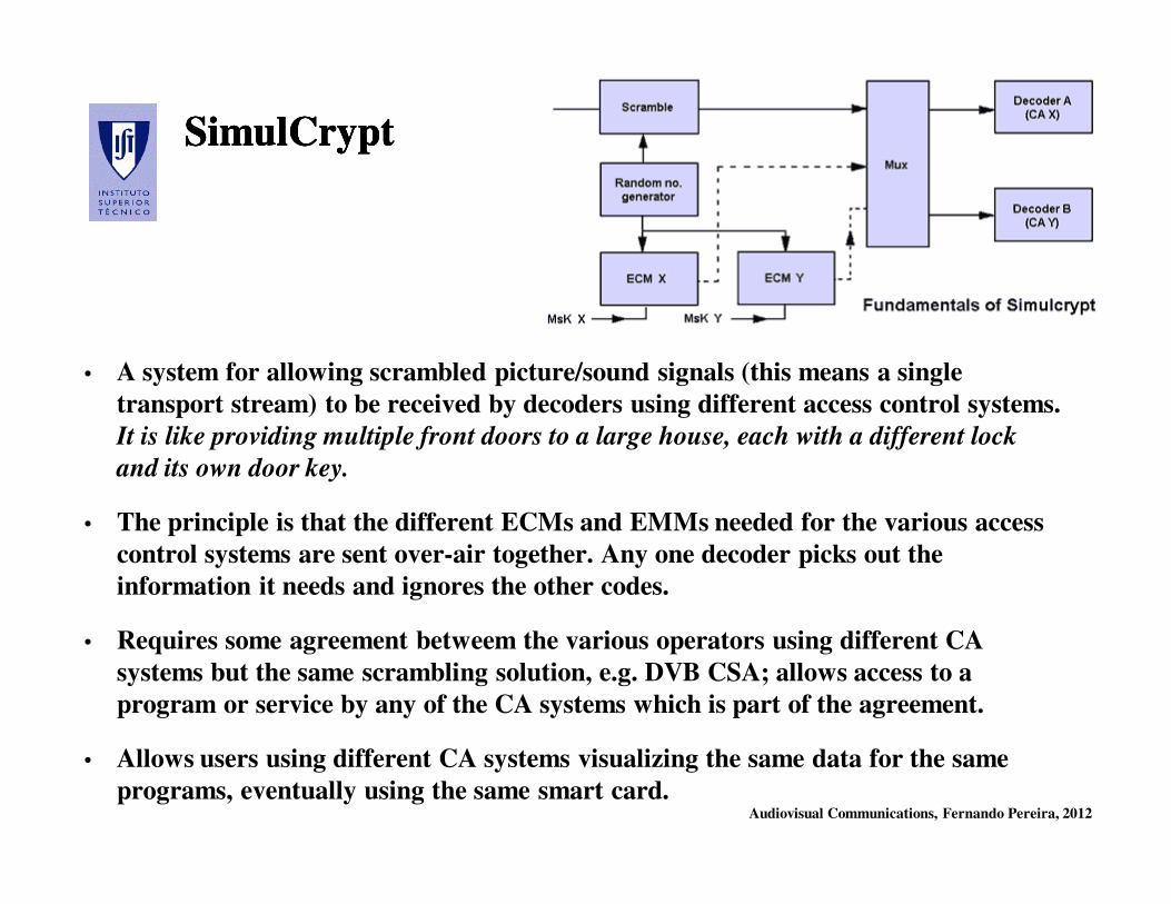
Audiovisual Communications, Fernando Pereira, 2012
SimulCryptSimulCryptSimulCryptSimulCrypt
• A system for allowing scrambled picture/sound signals (this means a single
transport stream) to be received by decoders using different access control systems.
It is like providing multiple front doors to a large house, each with a different lock
and its own door key.
• The principle is that the different ECMs and EMMs needed for the various access
control systems are sent over-air together. Any one decoder picks out the
information it needs and ignores the other codes.
• Requires some agreement betweem the various operators using different CA
systems but the same scrambling solution, e.g. DVB CSA; allows access to a
program or service by any of the CA systems which is part of the agreement.
• Allows users using different CA systems visualizing the same data for the same
programs, eventually using the same smart card.
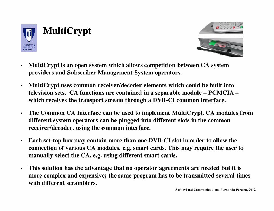
Audiovisual Communications, Fernando Pereira, 2012
MultiCryptMultiCryptMultiCryptMultiCrypt
• MultiCrypt is an open system which allows competition between CA system
providers and Subscriber Management System operators.
• MultiCrypt uses common receiver/decoder elements which could be built into
television sets. CA functions are contained in a separable module – PCMCIA –
which receives the transport stream through a DVB-CI common interface.
• The Common CA Interface can be used to implement MultiCrypt. CA modules from
different system operators can be plugged into different slots in the common
receiver/decoder, using the common interface.
• Each set-top box may contain more than one DVB-CI slot in order to allow the
connection of various CA modules, e.g. smart cards. This may require the user to
manually select the CA, e.g. using different smart cards.
• This solution has the advantage that no operator agreements are needed but it is
more complex and expensive; the same program has to be transmitted several times
with different scramblers.
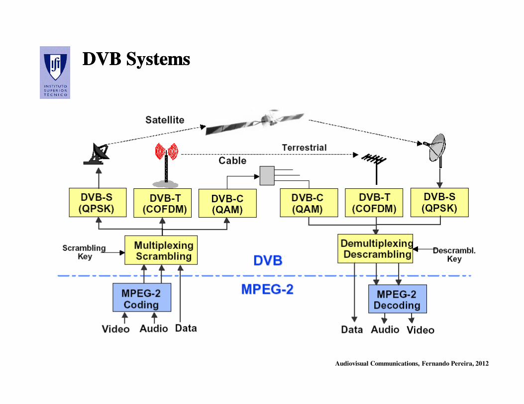
Audiovisual Communications, Fernando Pereira, 2012
DVB SystemsDVB SystemsDVB SystemsDVB Systems
Audiovisual Communications, Fernando Pereira, 2012
DVB TerminalsDVB Terminals
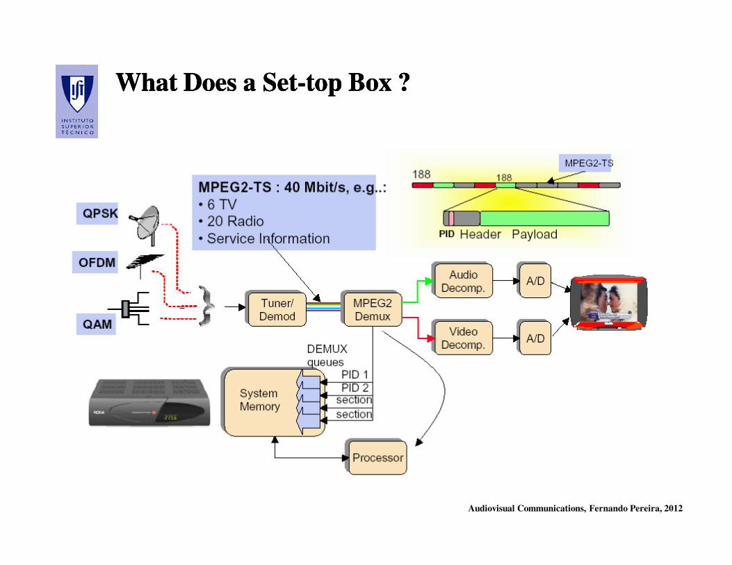
Audiovisual Communications, Fernando Pereira, 2012
What Does a SetWhat Does a Set--top Box ?top Box ?What Does a SetWhat Does a Set--top Box ?top Box ?
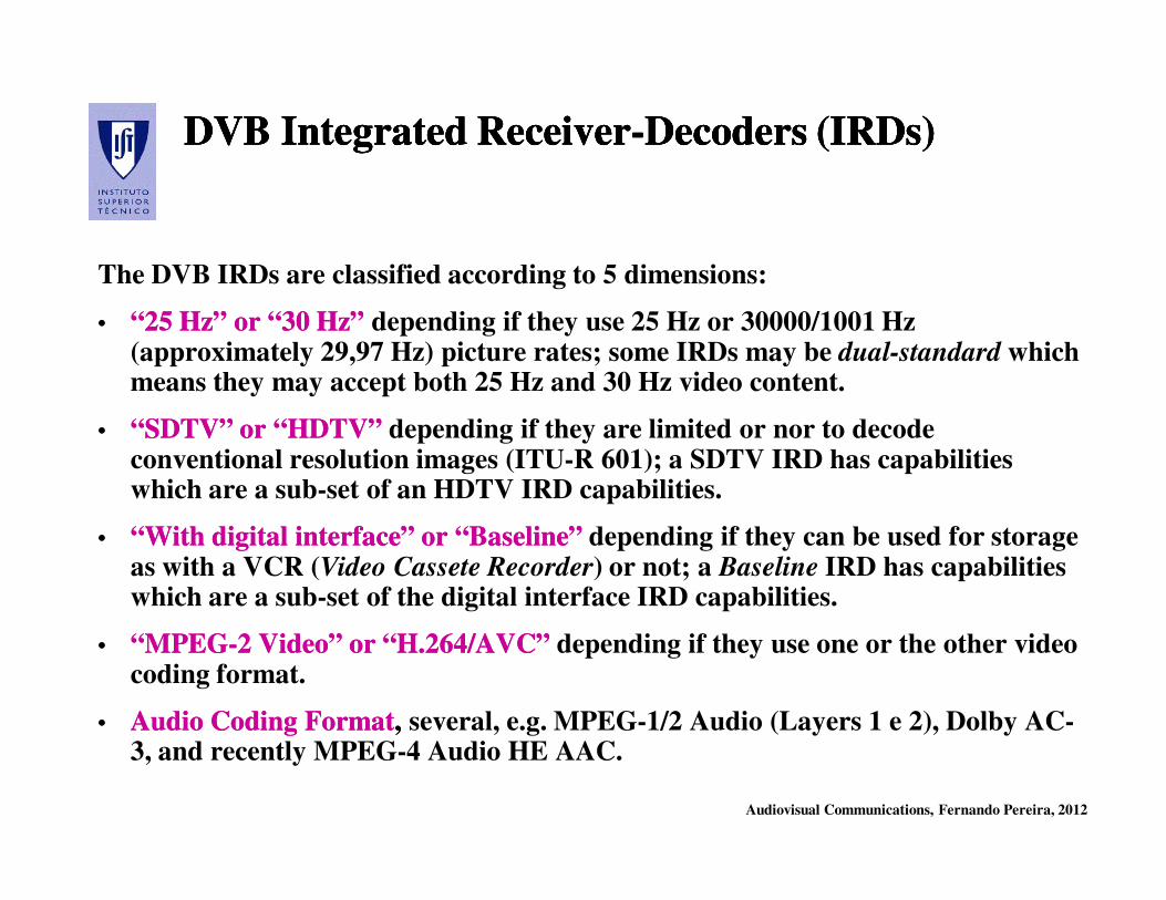
Audiovisual Communications, Fernando Pereira, 2012
DVB Integrated ReceiverDVB Integrated Receiver--Decoders (IRDs)Decoders (IRDs)DVB Integrated ReceiverDVB Integrated Receiver--Decoders (IRDs)Decoders (IRDs)
The DVB IRDs are classified according to 5 dimensions:
•• “25 Hz” or “30 Hz”“25 Hz” or “30 Hz” depending if they use 25 Hz or 30000/1001 Hz (approximately 29,97 Hz) picture rates; some IRDs may be dual-standard which means they may accept both 25 Hz and 30 Hz video content.
•• “SDTV” or “HDTV”“SDTV” or “HDTV” depending if they are limited or nor to decode conventional resolution images (ITU-R 601); a SDTV IRD has capabilities which are a sub-set of an HDTV IRD capabilities.
•• “With digital interface” or “Baseline”“With digital interface” or “Baseline” depending if they can be used for storage as with a VCR (Video Cassete Recorder) or not; a Baseline IRD has capabilities which are a sub-set of the digital interface IRD capabilities.
•• “MPEG“MPEG--2 Video” or “H.264/AVC”2 Video” or “H.264/AVC” depending if they use one or the other video coding format.
•• Audio Coding FormatAudio Coding Format, , several, e.g. MPEG-1/2 Audio (Layers 1 e 2), Dolby AC-3, and recently MPEG-4 Audio HE AAC.
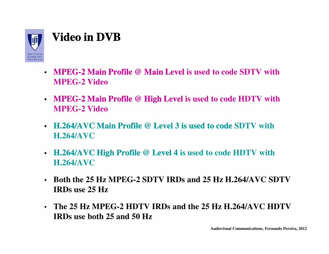
Audiovisual Communications, Fernando Pereira, 2012
Video in DVB Video in DVB Video in DVB Video in DVB
•• MPEGMPEG--2 Main Profile @ Main Level2 Main Profile @ Main Level is used to code SDTV with
MPEG-2 Video
•• MPEGMPEG--2 Main Profile @ High Level2 Main Profile @ High Level is used to code HDTV with
MPEG-2 Video
•• H.264/AVC Main Profile @ Level 3 is used to codeH.264/AVC Main Profile @ Level 3 is used to code SDTV with
H.264/AVC
•• H.264/AVC High Profile @ Level 4H.264/AVC High Profile @ Level 4 is used to code HDTV with
H.264/AVC
• Both the 25 Hz MPEG-2 SDTV IRDs and 25 Hz H.264/AVC SDTV
IRDs use 25 Hz
• The 25 Hz MPEG-2 HDTV IRDs and the 25 Hz H.264/AVC HDTV
IRDs use both 25 and 50 Hz
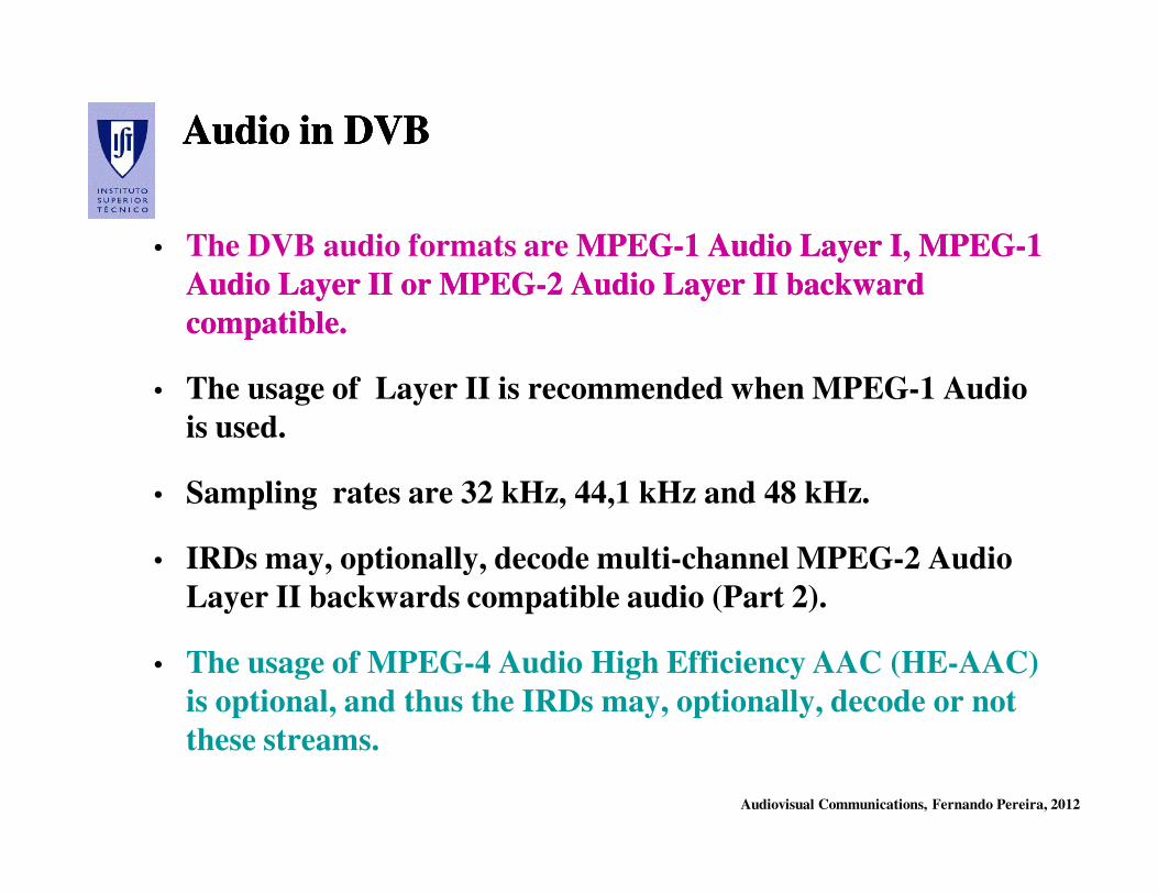
Audiovisual Communications, Fernando Pereira, 2012
Audio in DVB Audio in DVB Audio in DVB Audio in DVB
• The DVB audio formats are MPEGMPEG--1 Audio Layer I, MPEG1 Audio Layer I, MPEG--1 1
Audio Layer II or MPEGAudio Layer II or MPEG--2 Audio Layer II backward 2 Audio Layer II backward
compatible.compatible.
• The usage of Layer II is recommended when MPEG-1 Audio
is used.
• Sampling rates are 32 kHz, 44,1 kHz and 48 kHz.
• IRDs may, optionally, decode multi-channel MPEG-2 Audio
Layer II backwards compatible audio (Part 2).
• The usage of MPEG-4 Audio High Efficiency AAC (HE-AAC)
is optional, and thus the IRDs may, optionally, decode or not
these streams.

Audiovisual Communications, Fernando Pereira, 2012
Final RemarksFinal RemarksFinal RemarksFinal Remarks
• The DVB solutions for digital TV are recognized as the best, notably for
mobile and portable reception.
• There are many hundreds of millions of MPEG-2 (and now also
H.264/AVC) set-top boxes sold, especially in USA and Europe.
• Both Europe (DVB) and USA (ATSC) decided to use the MPEG-2
Systems and MPEG-2 Video standards (unfortunately with small
differences). While DVB also uses MPEG-2 Audio, ATSC uses Dolby
AC-3, another audio coding format.
• Digital Video Disc (DVD) has adopted MPEG-2 standards.
Much deployed digital TV Much deployed digital TV is still is still MPEGMPEG--2 based … however, 2 based … however,
another more efficient video coding solution is quickly taking another more efficient video coding solution is quickly taking
over: H.264/AVC (see next episode)!over: H.264/AVC (see next episode)!
Audiovisual Communications, Fernando Pereira, 2012
BibliographyBibliographyBibliographyBibliography
• H. Benoit, Digital Television: MPEG-1, MPEG-2 and principles
of the DVB system, Arnold, 1997
• U. Reimers, Digital Video Broadcasting, Springer Verlag, 2001
• B.Haskell, A. Puri, A. Netravali, Digital Video: an Introduction
to MPEG-2, Chapman & Hall, 1997
• R. de Bruin, J. Smits, Digital Video Broadcasting, Artech
House, 1998