cat.no. etj-0006 -nsk... · nsk do brasil industria e comercio de rolamentos ltda. sÃo paulo rua...
TRANSCRIPT

1999No.6
No.6 1999
No
.6 1
99
9

MOTION & CONTROL No. 6NSK Technical JournalPrinted and Published: June 1999ISSN1342-3630Publisher: NSK Ltd., Ohsaki, Tokyo, JAPAN
Public Relations DepartmentTEL +81-3-3779-7051FAX +81-3-3779-7431
Editor: Kyozaburo FURUMURAManaging Editor: Yasuhiko MORITADesign & Typesetting: Fuji Ad. Systems Corp.Printing: Kuge Printing K.K.
© by NSK Ltd.The contents of this Journal are the copyright of NSK Ltd.
Front cover: Soja Plant, NSK Ltd. (Japan)Peterlee Plant, NASTECH Europe Ltd. (U.K.)Clarinda Plant, NSK Corporation (U.S.A.)
NSK LTD.-Headquarters http://www.nsk.comAMERICAS & EUROPE Nissei Bldg., 6-3, Ohsaki 1-chome, Shinagawa-ku, Tokyo 141-8560, JapanDEPARTMENT P.: 03-3779-7120 F.: 03-3779-7433 T.: 2224280 NSK BRG J C.: 81ASIA MARKETING & Nissei Bldg., 6-3, Ohsaki 1-chome, Shinagawa-ku, Tokyo 141-8560, JapanSALES DEPARTMENT P.: 03-3779-7121 F.: 03-3779-7433 T.: 2224280 NSK BRG J C.: 81NSK AMERICAS, INC. [AMERICAN HEADQUARTERS]ANN ARBOR 3861 Research Park Drive, Box 1507, Ann Arbor, Michigan 48106-1507, U.S.A.
P.: 734-761-9500 F.: 734-761-9511 C.: 1NSK CORPORATION[CORPORATE OFFICE, Aftermarket Business Unit, OEM Business Unit]ANN ARBOR 3861 Research Park Drive, Box 1507, Ann Arbor, Michigan 48106-1507, U.S.A.
P.: 734-761-9500 F.: 734-761-9511, 734-668-7888 C.: 1[Precision Products Business Unit]CHICAGO 250 Covington Drive, Bloomingdale, Illinois 60108, U.S.A.
P.: 630-924-8000 F.: 630-924-8197 C.: 1[TECHNICAL CENTER]ANN ARBOR 3917 Research Park Drive, Ann Arbor, Michigan 48108, U.S.A.
P.: 734-668-0877 F.: 734-668-0852 C.: 1[BRANCHES and DISTRIBUTION CENTERS]LOS ANGELES 13921 Bettencourt Street, Cerritos, California 90703, U.S.A.
P.: 562-926-2975 F.: 562-926-3553 C.: 1SAN JOSE 1900 McCarthy Boulevard, Suite 107, Milpitas, California 95035, U.S.A.
P.: 408-944-9400 F.: 408-944-9405 C.: 1INDIANAPOLIS 5550 Progress Road, Park Fletcher, Indianapolis, Indiana 46241, U.S.A.
P.: 317-247-4724 F.: 317-247-5660 C.: 1ATLANTA 5575 Gwaltney Drive, Atlanta, Georgia 30336, U.S.A.
P.: 404-349-2888 F.: 404-349-1209 C.: 1[PLANTS]ANN ARBOR 5400 South State Road, Box 990, Ann Arbor, Michigan 48108, U.S.A.PLANT P.: 734-996-4400 F.: 734-996-4707 C.: 1CLARINDA 1100 N First Street, Clarinda, lowa 51632, U.S.A.PLANT P.: 712-542-5121 F.: 712-542-4905 C.: 1FRANKLIN 3400 Bearing Drive, Franklin, Indiana 46131, U.S.A.PLANT P.: 317-738-5000 F.: 317-738-4310 C.: 1LIBERTY 1112 East Kitchel Road, Liberty Indiana 47353, U.S.A.PLANT P.: (765) 458-5000 F.: (765) 458-7832 C.: 1NASTECHCORPORATE 110 Shields Drive Route 2, Box 0030 Bennington, Vermont 05201, U.S.A.OFFICE/PLANT P.: 802-442-5448 F.: 802-442-2253 C.: 1SALES OFFICE 2851 Boardwalk Drive, Ann Arbor, Michigan 48104, U.S.A.
P.: 734-669-8272 F.: 734-669-8102 C.: 1NSK SAFETY TECHNOLOGY, INC.DETROIT 281 Enterprise Court Suite 100, Bloomfield Hills, Michigan 48302, U.S.A.
P.: 248-338-4959 F.: 248-338-3208 C.: 1SAN DIEGO 2320 Paseo de las Americas, Suite 106, San Diego, California 92173, U.S.A.
P.: 619-661-6171 F.: 619-661-7175 C.: 1TIJUANA PLANT Calle Aguila Coronada No. 2000, Parque Industrial Bajama 9 El aguila,
Tijuana, Baja California, MexicoP.: 619-661-5500 F.: 619-661-1228 C.: 1P.: 66-25-53-02 F.: 66-25-53-10 C.: 52
NSK-RHP AMERICAN DISTRIBUTION CENTER, INC.MIAMI 5201 Blue Lagoon Drive, Suite 670, Miami, Florida 33126, U.S.A.
P.: (305) 261-7824 F.: (305) 261-6246, (305) 267-7447 C.: 1NSK-RHP CANADA INC.HEAD OFFICE 5585 McAdam Road, Mississauga, Ontario L4Z 1N4, Canada
P.: 905-890-0740 F.: 905-890-0434 C.: 1MONTREAL 2150-32E Avenue, Lachine, Quebec H8T 3H7, Canada
P.: 514-633-1220 F.: 514-633-8164 C.: 1TORONTO 5585 McAdam Road, Mississauga, Ontario L4Z 1N4, Canada
P.: 905-890-0561 F.: 905-890-1938 C.: 1EDMONTON 9527 49th Avenue, Edmonton, Alberta T6E 5Z5, Canada
P.: 604-294-1151 F.: 604-294-1407 C.: 1VANCOUVER 3353 Wayburne Drive, Burnaby, British Columbia V5G 4L4, Canada
P.: 604-294-1151 F.: 604-294-1407 C.: 1NSK RODAMIENTOS MEXICANA, S.A. DE C.V.MEXICO CITY Minas Palacio No.42-6, Col. San Antonio Zomeyucan Naucalpan de Juarez,
C.P. 53750 Estado de Mexico, MexicoP.: 5-301-2741, 5-301-3115, 5-301-4762 F.: 5-301-2244, 5-301-2865 C.: 52
NSK DO BRASIL INDUSTRIA E COMERCIO DE ROLAMENTOS LTDA.SÃO PAULO Rua 13 de Maio, 1633-14°. Andar, CEP: 01327-905-Bela Vista-São Paulo-SP, Brazil
P.: 011-269-4700 F.: 011-269-4720 C.: 55PORTO ALEGRE Rua Cãncio Gomes, 502-Sala 204, CEP: 90220-060, Porto Alegre, RS, Brazil
P.: 051-222-1324 F.: 051-222-2599 C.: 55BELO HORIZONTE Rua Cearã, 1431-Sala 405, CEP: 30150-311, Belo Horizonte, MG, Brazil
P.: 031-274-2477 F.: 031-273-4408 C.: 55JOINVILLE Rua Mário Lobo, 61-Sala 1112-11°. Andar, CEP: 89201-330, Joinville, SC, Brazil
P.: 047-422-5445 F.: 047-422-2817 C.: 55RECIFE Av. Conselheiro Aguiar, 2738 Conj. 604, CEP: 51020-020, Recife, PE, Brazil
P.: 081-326-3781 F.: 081-326-5047 C.: 55ARGENTINA Calle Maipu 325-7B CP. 1006 Buenos Aires-Argentina
P.: 11-4325-7855 F.: 11-4328-0128 C.: 54SUZANO PLANT Av. Vereador João Batista Fitipaldi, 66, CEP: 08685-000-Vila Maluf, Suzano, SP, Brazil
P.: 011-7701-4007 F.: 011-4748-2355 C.: 55NSK-RHP EUROPE LTD. [EUROPEAN HEADQUARTERS]RUDDINGTON Mere Way, Ruddington, Nottinghamshire, NG11 6JZ U.K.
P.: 0115-936-6464 F.: 0115-936-6400 C.: 44NSK-RHP EUROPE LTD. WARSAW LIAISON OFFICEWARSAW LIAISON Oddzial w Warszawie, ul. Migdalowa 4 lok. 73, 02-796 Warsaw, PolandOFFICE P.: 022-645-1525, 1526 F.: 022-645-1529 C.: 48NSK BEARINGS EUROPE LTD.OFFICE/BEARING 3 Brindley Road, South West Industrial Estate, Peterlee, Co. Durham, SR8 2JD U.K.PLANT P.: 0191-586-6111 F.: 0191-586-3482 C.: 44FORGE PLANT Davey Drive, North West Industrial Estate, Peterlee Co. Durham, SR8 2PW U.K.
P.: 0191-518-0777 F.: 0191-518-0303 C.: 44NSK-RHP EUROPEAN TECHNOLOGY CO., LTD.RUDDINGTON Mere Way, Ruddington, Nottinghamshire, NG11 6JZ U.K.
P.: 0115-940-5409 F.: 0115-940-5419 C.: 44NSK-RHP UK LTD.RUDDINGTON Mere Way, Ruddington, Nottinghamshire, NG11 6JZ U.K.
P.: 0115-936-6600 F.: 0115-936-6702 C.: 44NSK-RHP DEUTSCHLAND GMBH.DÜSSELDORF Harkortstr. 15, 40880 Ratingen, Germany
P.: 02102-481-0 F.: 02102-481-229 C.: 49STUTTGART Sielminger Str. 65, 70771 Leinfelden-Echterdingen, Germany
P.: 0711-79082-0 F.: 0711-79082-99 C.: 49LEIPZIG Zschortauer Str. 76, 04129 Leipzig, Germany
P.: 0341-5631241 F.: 0341-5631243 C.: 49NSK-RHP FRANCE S.A.PARIS Quartier de l’Europe, 2 Rue Georges Guynemer, 78283 Guyancourt Cedex, France
P.: 01 30 57 39 39 F.: 01 30 57 00 01 T.: 698578 C.: 33LYON Immeuble “Le Périphérique” 16, Rue des Brosses 69623 Villeurbanne Cedex, France
P.: 04 72 15 29 00 F.: 04 72 37 54 03 C.: 33NSK-RHP NEDERLAND B.V.AMSTERDAM Bouwerij 81, 1185XW. Amstelveen, The Netherlands
P.: 020-6470711 F.: 020-6455689 C.: 31NSK-RHP EUROPEAN DISTRIBUTION CENTRE B.V.AMSTERDAM Bouwerij 81, 1185XW. Amstelveen, The Netherlands
P.: 020-6470711 F.: 020-6455689 C.: 31NSK-RHP ITALIA S.P.A.MILANO Via XX Settembre, 30 20024 Garbagnate Milanese (Milano), Italia
P.: 02-995191 F.: 02-99025778, 02-99028373 C.: 39NSK-RHP IBERICA, S.A.BARCELONA Calle de la Hidráulica, 5, P.I. “La Ferreria” 08110 Montcada i Reixac (Barcelona), Spain
P.: 93-575-1662 F.: 93-575-0520 C.: 34
NSK ISKRA S.A.CORPORATE Ul. Jagiellonska 109, 25-734 Kielce PolandOFFICE/PLANT P.: 041-366-61-11 F.: 041-345-45-99 C.: 48NSK-RHP BEARINGS MIDDLE EAST TRADING CO., LTD.ISTANBUL Eski Uskudar Cad. Cayir Yolu Sok. Nora Center Kat 1, 81090 Icerenkoy, Istanbul, Turkey
P.: 216-463-6150 F.: 216-463-6147 C.: 90NSK-RHP SOUTH AFRICA (PTY) LTD.JOHANNESBURG 25 Galaxy Avenue, Linbro Business Park, Sandton, 2146, Gauteng, South Africa
P.: 011 (458) 3600 F.: 011 (458) 3608 C.: 27NASTECH EUROPE LTD.CORPORATE Torrington Avenue, Coventry CV4 9AE U.K.OFFICE/PLANT P.: 01203-854500 F.: 01203-854599 C.: 44PETERLEE 1 Palmer Road, South West Industrial Estate, Peterlee, Co. Durham SR8 2JJ U.K.PLANT P.: 0191-518-6800 F.: 0191-518-6808 C.: 44NSK INTERNATIONAL (SINGAPORE) PTE LTD.SINGAPORE 48 Toh Guan Road #04-02 Singapore 608837
P.: 2730357 F.: 2758937 C.: 65NSK SINGAPORE (PRIVATE) LTD.SINGAPORE 48 Toh Guan Road #02-03 Singapore 608837
P.: 2781711 F.: 2730253 T.: RS24058 C.: 65NSK-RHP AUSTRALIA PTY. LTD.MELBOURNE 11 Dalmore Drive, Scoresby, Victoria 3179, Australia
P.: 03-9764-8302 F.: 03-9764-8304 C.: 61SYDNEY Unit 1, Riverside Centre, 24-28 River Road West, Parramatta, N.S.W. 2150, Australia
P.: 02-9893-8322 F.: 02-9893-8406 C.: 61BRISBANE 91 Wellington Road, East Brisbane, Queensland 4169, Australia
P.: 07-3393-1388 F.: 07-3393-1236 C.: 61ADELAIDE 64 Greenhill Road, Wayville, South Australia 5034, Australia
P.: 08-8373-4811 F.: 08-8373-1053 C.: 61PERTH Unit 4, 36 Port Kembla Drive, Bibra Lake, Western Australia 6163, Australia
P.: 089-434-1311 F.: 089-434-1318 C.: 61NSK-RHP BEARINGS NEW ZEALAND LTD.AUCKLAND 3 Te A
.punga place Mt. Wellington Auckland New Zealand
P.: 09-276-4992 F.: 09-276-4082 C.: 64NSK BEARINGS (THAILAND) CO., LTD.BANGKOK 25th Floor RS Tower, Rachadaphisek Road, Dindaeng, Bangkok 10320, Thailand
P.: 02-6412150~58 F.: 02-6412161 C.: 66NSK SAFETY TECHNOLOGY (THAILAND) CO., LTD.
Amata Nakorn Industrial Estate 700/68 Moo 6 Bangna-Trad Rd.,T. Don-Hua-Roh A. Muang Chonburi 20000 ThailandP.: (038) 214-317-8 F.: (038) 214-316 C.: 66
SIAM NASTECH CO., LTD.90 Moo 9, Wellgrow Industrial Estate, Km. 36 Bangna-Trad Road, Bangwao, Bangpakong, Chachoengsao 24180, ThailandP.: 038-522-343~350 F.: 038-522-351 C.: 66
PT. NSK BEARINGS MANUFACTURING INDONESIAJAKARTA PLANT Blok M-4, Kawasan Berikat, MM2100 Industrial Town Cibitung, Bekasi 17520,
Jawa Barat, IndonesiaP.: 021-898-0155 F.: 021-898-0156, 021-898-0183 C.: 62
NSK BEARINGS (MALAYSIA) SDN. BHD.KUALA LUMPUR 1st Floor, Kompleks Kemajuan, No.2, Jalan 19/1B, 46300 Petaling Jaya,
Selangor Darul Ehsan, MalaysiaP.: 03-758-4396 F.: 03-758-4412 C.: 60
PRAI 10, Lengkok Kikik 1, Taman Inderawasih, 13600 Prai, Penang, MalaysiaP.: 04-399-1763 F.: 04-399-1830 C.: 60
JOHOR BAHRU Ground Floor, No. 27, Jalan Bakawali 50, Taman Johor Jaya, 81100 Johor Bahru, Johor, MalaysiaP.: 07-354-6290 F.: 07-354-6291 C.: 60
KOTA KINABALU Lot 10, Lrg. Kurma 4, Likas Ind. Centre, 5 1/2Miles, Jalan Tuaran, 88450 Inanam Sabah, MalaysiaP.: 088-421-260 F.: 088-421-261 C.: 60
NSK MICRO PRECISION (M) SDN. BHD.MALAYSIA PLANT No.43 Jalan Taming Dua,Taman Taming Jaya 43300 Balakong, Selangor
Darul Ehsan, MalaysiaP.: 03-961-6288 F.: 03-961-6488 C.: 60
RANE NASTECH LTD.14, Rajagopalan Salai, Vallanchery Village, Guduvanchery 603202. Kanchipuram District, Tamilnadu, IndiaP.: 4114-65313, 65314, 66002 F.: 4114-66001 C.: 91
NSK KOREA CO., LTD.SEOUL 9F(Western Hall) Posco Center 892, Deachi 4 Dong Kangnam-Ku, Seoul, Korea
P.: 02-3287-0300 F.: 02-3287-0345, 0445 C.: 82CHANGWON 60 Songsan-Dong, Chang-Won-Shi, Kyongsangnam-Do, KoreaPLANT P.: 0551-287-6001~4 F.: 0551-285-9982 C.: 82NSK-RHP HONG KONG LTD.
Room 512, Wing On Plaza, Tsim Sha Tsui East, Kowloon, Hong KongP.: 2739-9933 F.: 2739-9323 C.: 852
KUNSHAN NSK HS CO., LTD.258 South Huang Pu Jiang Rd Kunshan E&T Development Zone Jiang Su P.R., 215335, ChinaP.: 0520-7305654 F.: 0520-7305689 C.: 86
GUIZHOU HS NSK BEARINGS CO., LTD.Dongjiao, Anshun, Guizhou, 561000, ChinaP.: 0853-3521505 F.: 0853-3522722 C.: 86
TAIWAN NSK PRECISION CO., LTD.TAIPEI 9th Fl., 34, Chung Shan N. Rd., Sec. 3, Taipei Taiwan R.O.C.
P.: 02-2591-0656 F.: 02-2597-3101 C.: 886TAICHUNG 107-6, SEC, 3, Wenxin Rd., Taichung Taiwan R.O.C.
P.: 04-311-7978 F.: 04-311-2627 C.: 886NSK REPRESENTATIVE OFFICEPHILIPPINES Unit 910 PS Bank Tower Sen. Gil Puyat Avenue Corner Tindalo Street, MANILA Makati City 1200, Metro Manila, Philippines
P.: 02-759-6246~7 F.: 02-759-6249 C.: 63INDIA 2A, First Street, Cenotaph Road, Chennai, 600 018, IndiaCHENNAI P.: 044-4334732 F.: 044-4334733 C.: 91CHINA Room 515, Beijing Fortune Bldg., 5 Dong san Huan Bei Lu, Chao Yang District, BEIJING Beijing, 100004, China
P.: 010-6590-8161~3 F.: 010-6590-8166 C.: 86SHANGHAI Room 1005, Shanghai International Trade Center 2200 Yan An Road (w.),
Shanghai, 200336, ChinaP.: 21-6209-9051 F.: 21-6209-9053 C.: 86
GUANGZHOU Room 2802, Guangzhou International Electronics Tower 403,Huan Shi Rd East, Guangzhou, 510095, ChinaP.: 020-8732-0583 F.: 020-8732-0574 C.: 86
ANSHUN Dongjiao, Anshun, Guizhou, 561000, ChinaP.: 0853-3522522 F.: 0853-3522552 C.: 86
RHP BEARINGS LIMITEDGROUP P.O. Box 18, Northern Road, Newark, Nottinghamshire, NG24 2JF U.K.OFFICE P.: 01636-605123 F.: 01636-642083 T.: 377652 C.: 44NEWARK P.O. Box 18, Northern Road, Newark, Nottinghamshire, NG24 2JF U.K.PLANT P.: 01636-605123 F.: 01636-605000 T.: 377652 C.: 44FERRYBRIDGE Ferrybridge, Knottingley, West Yorkshire, WF11 8LS U.K.PLANT P.: 01977-674121 F.: 01977-674640 C.: 44BLACKBURN Roman Road Industrial Estate, Blackburn, Lancashire, BB1 2LZ U.K.PLANT P.: 01254-661921 F.: 01254-679502 C.: 44RHP PRECISION Bowbridge Road, Newark, Nottinghamshire, NG24 4BZ U.K.PLANT P.: 01636-605126 F.: 01636-613559 C.: 44RHP AEROSPACE Oldends Lane, Stonehouse, Gloucestershire, GL10 3RH U.K.PLANT P.: 01453-822333 F.: 01453-825945 C.: 44NEUWEG Postfach 1155, Ehinger Strasse 5, D-89593 Munderkingen, Germany(GERMANY) P.: 07393-540 F.: 07393-3732 C.: 49WIB Rue Champ-Barby 25, Ch-1630 Bulle, Switzerland(SWITZERLAND) P.: 026-9191100 F.: 026-9191120 C.: 41
P.: Phone F.: Fax T.: Telex C.: Country Code Printed in Japan
For more details, please contact any of the following NSK Offices.
World-wide Manufacturing and Marketing Organization
Specifications are subject to change without notice and without any obligation on the part of the manufacturer. Every care has been taken to ensure accuracy of the data containedin this catalog, but no liability can be accepted for any loss or damage suffered through errors or omission. We will gratefully acknowledge any additions or corrections.

ContentsBearings for Aircraft Gas Turbine Engines (part 2) –––––––––––––––––––––––––– 1
Electric Power Steering (EPS) ––––––––––––––––––––––––––––––––––––––––––––––– 9
Recent Development of NSK Direct-Drive Motors –––––––––––––––––––––––––– 16
New Electronic NSK Product Guide –––––––––––––––––––––––––––––––––––––––– 25
Sound and Vibration in Rolling Bearings ––––––––––––––––––––––––––––––––––– 29
New Products
Lightweight, Low-Cost TKZ Clutch Release Bearings –––––––––––––––––– 38
Cam-In Bearings™ —Bearings with Built-In One-Way Clutches ––––––––––––––––––––––––––––– 39
Maintenance-Free Precision Machinery Products with NSK K1™ Lubrication Units –––––––––––––––––––––––––––––––––––––– 40
No.6 (1999)

1 Motion & Control No. 6 — 1999
Bearings for Aircraft Gas TurbineEngines (part 2)Andrew Dodd, Nobuaki Mitamura and Hisashi Kawamura NSK-RHP European Technology CentreYukio OhuraPrecision Bearing Technology Department, Bearing Technology Center
1. Introduction
In recent years, new airline companies have emerged asa result of deregulation and increased demand in theindustry. On the other hand, alliances between airlineshave enhanced aircraft operating efficiency and consumerconvenience. An important trend resulting from the morewidespread use of aircraft transportation and the drive toimprove operating efficiency is developing aircraft withgreater long-range capability. Hence engines with higherfuel efficiency are being developed.
Twin-jet aircraft for medium and long range such as theBoeing 777 and Airbus A330 were developed to reduceoperating costs. In 1998, airlines flying cross-Atlanticroutes used twin-jet aircraft more than 50% of the time. Acritical contribution to the success of twin-jet aircraft hasbeen the availability of high-thrust turbofan engines withenhanced reliability.
In the development of the engine, improvement of themain shaft rolling bearing has been the key to overcomingvarious hurdles. Presently, important considerations forthe development of bearings for aircraft engines include:• The increased speed of the main shaft • Increased engine thrust and the resulting need for
higher bearing load capacity• The dependable performance of bearings in extreme
conditions (including oil interruption resulting fromchanges in the oil-level in the reservoir caused by anaircraft going into a nose-dive, and skidding, theexcessive sliding of rolling elements on the racewayunder high speed and low load)
• The assessment of bearing fatigue life in terms of L1 life(99% reliable life estimation)Day by day and application by application, requirements
from engine makers become increasingly exacting anddifficult for bearing manufacturers to meet. We areworking to ensure the highest bearing performance andreliability by taking the following measures:• Using high-fracture toughness and high-temperature
bearing steel (i.e., M50NiL, Pyrowear675, CSS-42L, etc.)for high-speed and high-capacity bearings
• Controlling the unbalance of rolling elements (balls androllers) in high-speed bearings
• Extending bearing life with plasma nitriding surfacetreatment
• Improving bearing fatigue life and resistance to slidingwear in medium-range temperatures (up to 300°C) byusing carbonitriding bearing steel (SHX)
These technologies are the fruits of developmental workboth on the internal properties of bearings (bearing steel,inclusions in material, microstructure, etc.) and externalproperties such as raceway surface-roughness and cage-guiding mechanisms. In this report, technologies thatcontribute to higher bearing reliability through improvingbearing internal properties are presented and discussed.
2. Improvements in Bearing Internal Properties
2.1 Improvement in unbalance of ballsBalls from bearings for high-speed applications
occasionally show signs of rolling and sliding contact inthe form of bands of concentric circles around theirexterior. In a study of three-dimensional ball motion,different traces of the projections of the north pole ofmagnetised balls were observed (Fig. 1).1) The moreunbalanced ball (Fig. 1a) tended to rotate more regularlyaround a fixed axis than the ball that was only slightlyunbalanced. It therefore appears likely that the rotationalaxis of unbalanced balls tends to be fixed as wearprogresses.
NSK measured the static and dynamic unbalance oflarge balls (15/8" dia.) made of M50 bearing steel foraerospace engine main-shaft bearings. We found that M50balls have very small static unbalance, less than 0.2 µm,which reflects good geometric accuracy, but have relativelylarge dynamic unbalance mainly caused by the unequal
1 200 2 000 3 000 3 900 5 000 6 600 8 000 10 000 11 000
1 200 2 000 3 000 3 900 5 000 7 000 8 000 10 000 10 000 12 000
Bearing (ball A: ε=3 µm unbalance)
(a)
(b)
Bearing (ball B: ε=0.3 µm unbalance)
T
T
ni
ni
392(N)
588(N)
392(N)
588(N)
800(rpm)
800(rpm)
Fig. 1 Traces of ball motion with different unbalance

Motion & Control No. 6 — 1999 2
distribution of carbides inside them, as shown in Photo 1. Therefore, the control of ball unbalance may beneeded for certain high-speed applications, particularlythose using large-sized balls.
2.2 Improvement in fracture resistance In the high-speed application of engine main-shaft
bearings, the dN value (dN = d: bearing bore diameter,mm × N: shaft speed, rpm) reaches 2.4 × 10⁶ and the innerring tends to break when this speed is exceeded. Ascountermeasures, case-hardened materials such asM50NiL and Pyrowear675 have been used because theyhave high compressive stress on the surface and highfracture toughness.
NSK has developed a testing method which canreproduce the fracture pattern of inner ring cracks thatoccur in actual bearings. For the first time, this methodenables the quantitative evaluation of the relationshipbetween hoop stress and inner ring fracture life byproviding a minute half-ellipse fatigue crack (pre-crack) ata selected “origin point” on the inner ring raceway. The
testing equipment is illustrated in Fig. 2. M50 andM50NiL were compared using this method and the resultsare shown in Fig. 3. An M50 inner ring under hoop stressof 270 MPa fractured after 1.5 × 10⁷ revolutions and under200 MPa hoop stress, a crack propagated but no fractureoccurred after 2.2 × 10⁷ revolutions (Fig. 4). In contrast,under higher hoop stress (280 MPa) and after far morerevolutions (1.7 × 10⁸), only slight crack propagation wasobserved with M50NiL steel (Fig. 5). The advantage ofM50NiL in terms of fatigue crack life was thus verifiedquantitatively.
2.3 Improvement in rolling contact fatigueproperties by surface modification
Bearing materials are required with improved rollingcontact fatigue (r.c.f.) and wear resistance together withgreater tolerance to poor lubrication conditions. The
Test bearing
Pre-crack
Fig. 2 Cross-section of inner ring fracture test machine
Photo 1 Distribution of Cr in M50 ball
500
450
400
350
300
250
200
150
100
SAE52100 with standard heat treatment (Residual stress: σ = 0~20 MPa)
SAE52100 with standard heat treatment (No pre-cracks. Crack initiated by inclusion)
M50 (σ R = –20 ~ –50 MPa ) M50NiL (σ R = –250 ~ –300 MPa )( : Discontinued, no failure)
R
Hoo
p st
ress
σt,
MP
a
P/C = 0.28
105 106 107 108 109
Life, revolutions
Fig. 3 Results of inner ring fracture test (P/C = 0.19)
Fig. 4 Pre-crack and fatigue crack propagation (M50, Hoop stress σt = 200 MPa, n = 2.2 × 10⁷ rev.)
A (Pre-crack)B (Fatigue crack propagation zone)
C (Section broken on purpose) 5 mm

3 Motion & Control No. 6 — 1999
development of new materials to meet these requirementsis costly and slow due to the safety critical nature of theapplication. Alternatively, surface treatments, particularlythermochemical treatments such as nitriding andnitrocarburising, can be used to enhance the properties ofexisting bearing materials. It has been shown thatnitrocarburised bearing raceways made in M50 andM50NiL materials performed better than untreatedraceways in conditions of contamination, surface flaws,marginal lubrication and traction.2) The nitrocarburisingtreatment, however, involves high temperatures (>500°C)and long process times (up to 32 hours) and a finalgrinding operation is required to remove the compound
layer which performs unfavourably in r.c.f.3)
Outlined in this section is a plasma nitriding processdeveloped by NSK-RHP for M50 and M50NiL bearingmaterials. The process is performed at significantly lowertemperatures and reduced process times compared toother nitriding/nitrocarburising treatments for bearingmaterials. Furthermore, the process conditions are suchthat the formation of a compound layer is prevented anddistortion is maintained within acceptable levels therebynegating the need for a final grinding operation. Fatiguetesting of M50 and M50NiL materials under high Hertziancontact stresses and marginal lubrication has shown thatplasma nitriding significantly improves the r.c.f.resistance of both materials.
2.3.1 MaterialsThe plasma nitriding process was developed for M50 and
M50NiL main-shaft bearing materials. The composition ofM50 and M50NiL is given in Table 1 together with that ofSAE52100 carbon chrome bearing steel for comparison.
M50 material is a well-established through-hardeningbearing steel and is the most commonly used material formain-shaft bearings. M50NiL material, which wasintroduced more recently in the 1980s, is the carburisingversion of M50. M50NiL has similar bearing properties toM50 but higher fracture toughness in the uncarburised core.
2.3.2 PropertiesTo improve the r.c.f. resistance, wear/scuffing resistance
and tolerance to poor lubrication conditions of M50 andM50NiL materials, a plasma nitriding process wasdeveloped that produces the following materialenhancements.(1) Surface hardness
In general the higher the surface hardness the greaterthe resistance to wear and debris damage. The normalsurface hardness of M50 and M50NiL materials is around750 Hv. Increasing this surface hardness by plasmanitriding would be expected to improve the wearresistance.
The surface hardness achieved by the plasma nitridingprocess was 975±25 Hv (Fig. 6). Although a much highersurface hardness can be achieved by plasma nitriding, amaximum of 1 000 Hv was set to limit the hardnessdifferential between the nitrided case and the bulkmaterial. By reducing the hardness differential thelikelihood of cracking in the region of the interface betweenthe nitrided case and the bulk material is reduced.(2) Nitrided case depth
The plasma nitrided case depth achieved was 50±25 µm(Fig. 6) which reflects the amount of wear that can be
Material
Chemical composition (wt%)
C Cr Mn Mo Ni Si V
M50 0.8 4.1 0.3 4.3 – 0.3 1.1
M50NiL 0.1 4.1 0.3 4.3 3.4 0.2 1.2
SAE52100 1.0 1.5 0.4 – – 0.3 –
Table 1 Composition of test materials
3.7 mm
0.67
mm
Pre-crack
Pre-crack
A
Fatigue crack propagation zone
Fatigue crack propagation zone
Section broken on purpose
Section broken on purpose
0.15 mm
Magnification of section A
Fig. 5 Pre-crack and fatigue crack propagation (M50NiL, Hoop stress σt = 280 MPa, n = 1.7 × 10⁸ rev.)
Pre-crack and fatigue crack propagation zone

Motion & Control No. 6 — 1999 4
tolerated by the bearing. Also, by adopting a relativelyshallow case, the process conditions (time andtemperature) can be kept to a minimum. This not onlyreduces cost but also the amount of distortion and thelikelihood of the formation of undesirable microstructuralfeatures. Furthermore, because the specified case depth iswell below the calculated depth to maximum shear stressfor main-shaft bearings, the likelihood of subsurfacecracking is reduced.(3) Microstructure
Generally, plasma nitriding results in the formation of acompound layer (white layer) on the surface that is usuallyseveral microns thick. The compound layer, which ispredominately iron nitride, is very hard and enhances thewear resistance of the material. However, the compoundlayer is friable and prone to break down under theinfluence of the high cyclic stresses experienced by abearing during service. The process conditions developedby NSK-RHP are such that the formation of a compoundlayer on the surface is prevented.
Similarly, the plasma nitriding conditions developed donot result in the formation of grain boundary precipitatesof carbonitrides. These can act in the same way as carbidenetworks to reduce the r.c.f. resistance.(4) Distortion
Generally, thermochemical treatments such as nitridingand carburising cause distortion. It is important that thedistortion produced as a result of the plasma nitriding
process can be accommodated within the design of thebearing. Measurement of actual main-shaft bearing ringsbefore and after plasma nitriding, see Table 2, has shownthat the distortion is of the order of microns and can beallowed for in the design of the bearing.(5) Residual stress
In addition to causing distortion, thermochemicaltreatments can produce residual stresses in the surface ofthe bearing rings. In the case of M50NiL material,carburising produces a high compressive stress in thecarburised case that enhances the performance of thematerial. It is therefore important that the plasmanitriding does not adversely affect the residual stress inthe materials.
Measurement of the residual stress in bearing racewaysmade in M50 and M50NiL materials has revealed that theplasma nitriding process increases the level of compressivestress in the surface. In the case of M50NiL, thecompressive residual stress at the surface was increasedon average by 400 MPa (Fig. 7). The effect on the depthprofile was less pronounced with a slight increase in thelevel of compressive stress to a depth of around 0.5 mm(Fig. 8).
2.3.3 Fatigue testingTo assess the effect of plasma nitriding on the r.c.f.
resistance of M50 and M50NiL under marginallubrication, Polymet testing was carried out (Fig. 9).
Normal hardness of M50 material
Mic
ro-h
ardn
ess
(Hv
0.1)
950
900
850
800
750
7000.0 0.5 1.0 1.5
Depth below raceway, mm(a) M50
(b) M50NiL
Depth below raceway, mm
Plasma nitrided
StandardPlasma nitrided
Mic
ro-h
ardn
ess
(Hv
0.1)
1 000
900
800
700
6000.0 0.1 0.2 0.3 0.4 0.5
Fig. 6 Hardness profile of (a) M50 and (b) M50NiL before and afterplasma nitriding
-800
-1 000
-1 200
-1 400
-1 600
-1 800
-2 0000 90 180 270 360
Res
idua
l str
ess,
MP
a
StandardPlasma nitrided
Rotation around the raceway, degrees
Fig. 7 Residual stress in the surface of M50NiL before and afterplasma nitriding
Variance (µm)
Ring No. 1 Ring No. 2
Dimension:
Outer diameter +8 +6
Track +6 +2
Width +4 –
Bore +4 –
Roundness:
Outer diameter +0.76 +0.65
Track +1.03 +1.15
Ring No. 1, outer diameter = 283 mmRing No. 2, outer diameter = 181 mm
Table 2 Distortion by plasma nitriding

5 Motion & Control No. 6 — 1999
In brief, the Polymet test involves the use of testspecimens, nominally 9.5 mm in diameter by 76 mm inlength. The specimens are diametrically loaded by twohardened M50 steel discs while rotating at a constantspeed of 12 500 rpm. The maximum Hertzian stressinduced in the test specimen by the discs is 4.8 GPa. The lubricant, synthetic gas turbine oil, is drip-fed from areservoir onto the specimen/disc contact. The lambdavalue for the Polymet test is less than one, i.e., marginallubrication.
The test normally continues until the test specimen failsby the generation of a r.c.f. spall. The results of the Polymettesting, plotted on the Weibull probability scale ofcumulative percentage of failure versus number of stressrepetitions, are shown in Fig. 10 and summarised in Table 3.
The baseline and plasma nitrided specimens were allmade in material from the same cast and as part of thesame manufacturing batch. The testing of the baseline andplasma nitrided specimens was interlaced to eliminate anyvariation caused by the Polymet test machine.
The results show that under conditions of high Hertziancontact stress and marginal lubrication, plasma nitridinghas improved the r.c.f. resistance of both M50 and M50NiLmaterials. In the case of M50 material, the L10 life wasincreased by more than a factor of 10.
2.4. Long-life material for high temperatures:“SHX”
The need for bearings that can perform at elevatedtemperatures is growing as machine speeds increase andthe space in which bearings operate becomes moreconfined. The design of high-temperature bearingsrequires more care than the design of bearings for normaltemperatures. NSK has analysed the failure of bearingsoperating at high temperatures and used the findings todevelop new long-life bearing materials. SHX, with therequired properties for use at high temperatures, is one ofthese newly developed materials.
2.4.1 Bearing properties required for high-temperature applications
Materials for bearings that operate at elevatedtemperatures require a number of properties. Among theseis good dimensional stability. In the case of standardbearing materials, good dimensional stability is achievedby tempering at higher than normal tempering
99
90
50
10
11 10 100 1 000
Per
cent
faile
d
M50 Baseline
M50 Plasma nitrided
M50NiL Plasma nitrided
Million stress cycles
99
90
50
10
11 10 100
Per
cent
faile
d
Million stress cycles
M50NiL Baseline
Fig. 10 Polymet results for plasma nitrided M50 and M50NiL materials
Table 3 Fatigue life test results
Weibull analysis
Material Stress repetitions × 106
SlopeL10 L50
M50 Baseline 2.4 4.9 2.6
M50 Plasma nitrided 28.8 87.8 1.7
M50NiL Baseline 2.3 4.5 2.8
M50NiL Plasma nitrided 10.6 24.2 2.3
Test conditions:Contact stress: 4.8 GPaSpeed: 12 500 rpmLubricant: Castrol 599Lambda: 0.9
Oil reservoir
Test specimendriven by inline motor
Accelerometer
Loadingmechanism
Locating discs: hemispherically ground
Fig. 9 Schematic of a Polymet test machine
500
0
-500
-1 000
-1 500
Res
idua
l str
ess,
MP
a
StandardPlasma nitrided
Depth below the surface, mm
0.0 0.5 1.0 1.5 2.0
Fig. 8 M50NiL residual stress vs. depth profile before and afterplasma nitriding

Motion & Control No. 6 — 1999 6
temperatures to remove the retained austenite. Such high-temperature tempering, however, causes a reduction inhardness and correspondingly, fatigue life (Fig. 11).Therefore, in the past, fatigue life has been sacrificed togain good dimensional stability. Alternatively, more-expensive precipitation-hardening alloy steels have beenused in place of standard bearing steel.
2.4.2 Process of fatigue at high temperatures Research at NSK has revealed that fatigue at high
temperatures can be divided in to two types: subsurfaceand surface. This is similar to fatigue under normaltemperatures.4) At high temperatures, however, it wasdiscovered that the origin of failure in the case ofsubsurface fatigue was not just non-metallic inclusions but also areas of unusual microstructure (whitemicrostructure).
It was also discovered that at high temperatures thefrequency of surface fatigue was higher compared tonormal temperatures. This is because the oil viscosity andcorrespondingly, the oil film thickness decrease astemperature increases. At high temperatures, the oil filmthickness is often insufficient to prevent contact betweenthe rolling elements and raceway, and therefore wearoccurs. The process of this wear is accelerated bycontamination of the lubricating oil by wear debris. It isimportant to pay sufficient attention to this type of surfacefatigue as it can shorten life.
2.4.3 Development of long-life material• Improving surface fatigue resistance
It is known that material factors like retained austenite,residual stress and surface hardness have an effect onsurface fatigue resistance.5) In the case of high-temperature applications, however, increasing bearing lifeby controlling the amount of retained austenite is notsufficient. This is due to the fact that the large volume ofretained austenite responsible for long life is transformedat elevated temperatures, resulting in a reduction indimensional stability.
As retained austenite has been ruled out as a way ofimproving the life of bearings used at high temperatures,the main focus has been on the control of residual stressand surface hardness. To create SHX steel, a suitablemedium-carbon steel was carbonitrided to produce therequired surface residual stress and its hardness wasimproved by adding elements that have a beneficial effecton tempering resistance, such as silicon and molybdenum.Also, the nitrogen introduced during carbonitridingproduces an increase in surface hardness. Fig. 12compares the relationship between hardness andtempering temperature of conventional steels and the newSHX steel.
• Improving subsurface fatigue resistanceIn the case of subsurface fatigue it was discovered that
the origin of failure at high temperatures was non-metallicinclusions and areas of unusual microstructure. To reduce
the number of failures originating at non-metallicinclusions, the cleanliness of the steel was improved. To aid in improving steel cleanliness, NSK developed anew method for assessing steel cleanliness. This methodmakes use of extreme value statistics, and has beensuccessfully utilised to improve the cleanliness of the newSHX material.
In order to prevent failures that originate from areas ofunusual microstructure, an analysis was carried out toidentify elements that delay changes in microstructure.The investigation revealed that silicon, molybdenum andnitrogen, which are already added to SHX to improveresistance to surface fatigue, also delay microstructuralchanges.
2.4.4 Other property requirementsIn addition to good fatigue life, bearings that operate at
high temperatures also need to have good wear andseizure resistance. This is because the formation of an oilfilm at high temperatures is difficult. Work carried out byNSK has shown that controlled additions of nitrogen canimprove wear and seizure resistance.
Standard tempered bearingsHigh-temperature tempered bearings
C
Per
cent
faile
d
Life, h
99
90
50
10
5
11 10 100 300
Test conditions: Bearing temperature: 140°CP/C = 0.28Shaft speed: 4 900 rpmDebris: Diameter: 74 to 147 µm Hardness: 540 Hv Quantity: 150 ppm
Fig. 11 Comparison of fatigue life under high temperature withcontaminated lubrication (Surface fatigue)
900
800
700
600
500100 150 200 250 300 350
SHX: conventional bearing steel + Si, MoHeat treatment: Carbonitriding
Conventional bearing steel + SiCarbonitriding
Conventional bearing steelCarbonitriding
Conventional bearing steelCarburizing
Har
dnes
s, H
v
Tempering temperature, °C (× 2 hr)
Fig. 12 Tempering resistance

7 Motion & Control No. 6 — 1999
2.4.5 Properties of SHX bearing materialFig. 13 shows the dimensional change of SHX material
as a function of time at both 140 and 200°C. As the figureshows, the dimensional stability of SHX material isslightly inferior to M50 but superior to conventionalbearing steel tempered at high temperature.
Figs. 14 and 15 show the results of surface andsubsurface fatigue life tests, respectively. Clearly, theresistance of SHX material to both surface and subsurfacefatigue is superior to M50 and conventional bearing steeltempered at high temperature. The reason for the
relatively low life of M50 material despite its highhardness is thought to be due to the large carbides itcontains that have an adverse effect on fatigue life. Alsothe strength of the martensite matrix is reduced by thehigh-temperature tempering applied to the M50 material(>500°C).
Figs. 16 and 17 present the results of wear and seizuretests, respectively. As shown, the wear and seizureresistance of SHX material is superior to both M50 andconventional bearing steel tempered at high temperature.
3. Conclusion
Part 1 of this article, which appeared in the precedingissue of Motion and Control, focused on key operatingrequirements and the latest countermeasures for aircraftgas turbine engine bearings. Complementing Part 1, thispaper has explained some new technologies developed forthe improvement of the internal quality of the bearings.These new technologies include:• A testing method that for the first time enables the
quantitative evaluation of the relationship between hoopstress and inner ring fracture life
This testing method was used to demonstrate that
99
90
50
10
5
1106 107 108 109
Per
cent
faile
d
Test conditions:Test piece temperature: 130°CPmax: 5 500 MPaCycle stress speed: 3 000 cpmLubrication: Clean, L > 3
Stress cycles
SHXM50SAE52100High-temperature tempering
Fig. 15 Results of rolling element fatigue life test (Flat washer typetest) under high temperature with clean lubrication(Subsurface fatigue)
99
90
50
10
5
1100 101 102 103
Per
cent
faile
d
Test conditions:Bearing temperature: 140°CLoad: P/C = 0.28Shaft speed: 4 900 rpmDebris:
Diameter: 74 to 147 µmHardness: 540 HvQuantity: 150 ppm
Life , h
SHXM50SAE52100High-temperaturetempering
Fig. 14 Results of bearing fatigue life tests under high temperaturewith contaminated lubrication (Surface fatigue)
100
8060
40
20
5
0
-5
50
25
0
-25
-5010 100 1 000
Time, h
Time, h
10 000
1 000100 10 000
Temperature: 200°C
Temperature: 140°C
SHXM50SAE52100 High-temperature temperingSAE52100 Standard tempering
Dim
ensi
onal
cha
nge,
%D
imen
sion
al c
hang
e, %
× 10-3
× 10-3
Fig. 13 Dimensional stability at 140°C and 200°C

Motion & Control No. 6 — 1999 8
M50NiL steel has longer fatigue crack life than M50 steel.• A plasma nitriding process for M50 and M50NiL main-
shaft bearing materialsThis process increases the surface hardness to around
975 Hv and produces a nitrided case depth between 25and 75 µm. The process conditions are such that theformation of a compound layer on the surface isprevented and distortion is kept to a minimum.Consequently, plasma nitriding can be applied to thebearing components as the last process in theirmanufacture, with no subsequent machining required.Results of rolling contact fatigue testing showed thatplasma nitriding produces a significant improvement inthe r.c.f. life of both M50 and M50NiL materials undermarginal lubrication. In the case of M50 material, theL10 fatigue life was increased by more than a factor of 10.
• A new bearing material for use in high-temperatureconditions
The material, called SHX, not only has superiorfatigue strength but also better wear and seizureresistance than conventional bearing materials.The need by engine manufacturers to increase
performance while reducing cost and weight continues tobe a primary motivation behind R&D efforts. Developmentof bearing technology for materials, surface treatmentsand design is ongoing at NSK-RHP.
References:1) Kawamura, H. and Touma, K., “Motion of Unbalanced Balls in
High-Speed Angular Contact Ball Bearings,” J.Tribology,ASME, Vol. 112, 1 (1990) 105-110
2) M. M. Dezzani et al, “Hybrid Ceramic Bearings for DifficultApplications,” Presented at the Int. Gas Turbine & AeroengineCongress & Exposition, Houston, Texas, June 5-8, 1995
3) J. F. Braza, “Rolling Contact Fatigue Properties of FerriticNitrocarburised M50 Steel,” Tribology Transactions, Vol. 35, 1(1992) 89-97
4) Furumura, K., Murakami, Y., and Abe, T., “The Developmentof Bearing Steels for Long Life Rolling Bearings Under CleanLubrication and Contaminated Lubrication,” ASTM STP 1195(1993) 199-210
5) Shiratani, T., Murakami, Y., Abe, K. and Beerbower, M.P.,“Increasing Life with HTF Bearings for Transmissions,” SAETech. Paper Series 940728 (1994)
Andrew Dodd
Nobuaki Mitamura
Hisashi Kawamura
Yukio Ohura
0.04
0.03
0.02
0.01
00 500 1 000 1 500 2 000
SHXM50SAE52100High-temperaturetempering
Test conditions Sliding to roll ratio: 30% Lubrication: Oil drop-feed (Spindle oil)
Sliding distance, m
Am
ount
of w
ear,
g
Fig. 16 Wear resistance (Two-cylinder wear tester)
2 000
1 500
1 000
500
0SAE52100 M50 SHX
PV
val
ue, k
gf/m
m2
· m/s
Test conditions Ball size: 3/8 inch Lubrication: Oil bath Shaft speed: 6 000 rpm
Material
Test method:Measurement of PV value until seizure occurs with increasing load under constant speed.
Fig. 17 Seizure resistance (4-ball test)

9 Motion & Control No. 6 — 1999
Electric Power Steering (EPS)Yuji Kozaki, Goro Hirose, Shozo Sekiya and Yasuhiko Miyaura Steering Technology Department, Automotive Technology Center
1. Introduction
The effects of global warming are becoming increasinglyapparent. As a result, we product engineers are beingasked to develop products that are more friendly to theearth’s environment. Electric power steering (EPS) is sucha product. By using power only when the steering wheel isturned by the driver, it consumes approximately one-twentieth the energy of conventional hydraulic powersteering systems and, as it does not contain any oil, it doesnot pollute the environment both when it is produced anddiscarded. While offering these environmental benefitsnow, in the future EPS is expected to facilitate automaticsteering—user-friendly technology that should ultimatelyreduce traffic accidents. Additionally, the software builtinto the EPS controller results in high performance andeasy tuning during the development of prototypes of EPSsystems. Because of these advantages, EPS has drawn theattention of automobile manufacturers all over the world.The EPS systems we produce have the highest marketshare not only in Japan but in Europe as well. This reportoutlines the construction of the column-type and pinion-type EPS systems produced by our company, as well asgives a technical profile of their main components:electronic control unit (ECU), sensor and motor.
2. EPS System
The EPS system consists of a torque sensor, whichsenses the driver’s movements of the steering wheel aswell as the movement of the vehicle; an ECU, whichperforms calculations on assisting force based on signalsfrom the torque sensor; a motor, which produces turningforce according to output from the ECU; and a reductiongear, which increases the turning force from the motor andtransfers it to the steering mechanism. EPS is available in
two types: a column type in which the reduction gear islocated directly under the steering wheel, and a piniontype in which the reduction gear is attached to the pinionof the rack and pinion assembly. Each type of EPS systemis speed-sensitive—vehicle speed and engine rotationsignals are input from the vehicle into the ECU. Fig. 1shows a vehicle with column-type EPS.
3. General Description of Column-TypeEPS System
3.1 Construction of column-type EPSFig. 2 shows the construction of the column-type EPS
system. Collapsible safety columns are usually used. The unit is contained in the dashboard.
3.2 Column-type EPS seriesAlready ten years have passed since our column-type
EPS systems were introduced in mini-cars (<0.66l enginecapacity). During this period, we have worked to increasetheir applications in mini-cars and to expand their rangeof applications into small vehicles (approximately 0.66 to1.5l engine capacity). As a result, our series of column-type EPS systems is now being used by automobilemanufacturers in Japan and overseas. Table 1 lists fourcolumn-type EPS systems.
Fig. 1 A vehicle with column-type EPS
1
11 2 3 4 8 9 1012
5 7 6
1. Motor
2. Worm gear
3. Worm wheel
4. Torque sensor mechanism
5. Potentiometer
6. Motor harness
7. Torque sensor harness
8. Energy-absorbing convoluted tube
9. Keylock assembly
10. Switch bracket
11. Lower bracket
12. Rubber damper
Fig. 2 Construction of column-type EPS system

Motion & Control No. 6 — 1999 10
3.3 Output improvement and energy-absorbing mechanism
a. Response to output improvement In response to the improved output of EPS, we reviewed
current design standards with a focus on improvingendurance and impact strength. As a result, new designstandards compatible with the higher output of today’sEPS systems are now in place for the followingcomponents:
• worm and worm wheel gears• output shaft• bearing• joints and connections• mounting bracketIn addition, we achieved the serialized production of
plastic worm wheel gears and, through the use of coldforging, reduced the cost of producing sensor systemcomponents such as the output shaft.
b. Energy-absorbing mechanismGenerally, with column-type EPS systems, there is less
space available for the steering column to absorb energy inthe event of an accident because the EPS system is locatedon the column. However, based on the safety columntechnology we have cultivated, we have developed an EPSequipped with an energy-absorbing mechanism, motor,gears, torque sensor system, key lock housing, and switchbracket, in spite of the fact that the overall length from theinput shaft end to the output shaft end is restricted by thelayout of vehicles (see Fig. 2). The column assembly of thisEPS system has inner and outer column sections like aconventional EPS. In addition, for added safety inaccidents, it has a mechanism to soften its collapse, aconvoluted tube to absorb the driver’s energy, and a devicethat allows the lower bracket to absorb energy.
3.4 Reduction gear and rattling noiseBecause the steering wheel and reduction gear in a
column-type EPS are located close to each other, soundproduced in the reduction gear is directly transferred tothe vehicle interior, to the detriment of driving comfort. Toreduce this noise, our worm wheel gear is made of plastic.Moderate backlash is generally necessary for the meshingof gears, but the rattling noise of the gear teeth caused bybacklash can be particularly troublesome when the vehicleis running on a bad road. As today’s vehicles are requiredto be increasingly quiet, column-type EPS systems, whichare located in vehicle interiors, must operate withminimum noise.
3.5 Reducing rattling noiseThe rattling noise is caused by the teeth of the worm
and worm wheel gears colliding as a vehicle is running ona bumpy irregular road. The noise, which may sometimesbe perceived as self-excited vibration, becomes morenoticeable as backlash increases. As backlash isunavoidable with reduction gears, we developed an impactabsorption system that considerably reduces the rattlingnoise backlash generates.
A) Measures for reducing rattling noise Elimination or reduction of teeth noise• Lower backlash value• Impact absorption by elastic material• Review of gear specifications to reduce teeth noise
B) Optimum specifications for significant reduction ofrattling noise
To absorb impact effectively • Determine appropriate rigidity of rubber damper (Fig. 3)• Determine sufficient volume of rubber for impact
absorption
C) Reliability (endurance and strength)To achieve high reliability• Ensure rubber’s resistance to deterioration (deformation
from heat and repeated use)
D) Utilization of rubber damper characteristicsRubber damper applications:a.Impact damping
Cushioning impacts of stopper by utilizing the lowimpact resilience of rubber
b.Vibration absorption Vibration attenuation in resonance region by utilizingthe energy-absorbing property of rubber
Reduction gear ratio Electric current (A) Assist torque (N·m)
A 16.5 25 17.3
B 16.5 30 19.8
C 17 30 25.0
D 18 45 33.5
Table 1 Column-type EPS
1.0
0.5
10 20 30 40
Frequency, Hz
Electronic controlled mount
Hydraulic mount
Rubber mount
Loss
fact
or
Fig. 3 Characteristics of impact-damping rubber mounts

11 Motion & Control No. 6 — 1999
Rubber characteristics required for impact damping:a. Large loss factor (Fig. 3)
• Rubber material (physical properties)• Volume of rubber• Shape of rubber mass
b. Resistance to surrounding factors• Heat resistance• Resistance to deterioration from aging
(deformation from fatigue)• Resistance to year-round weather conditions• Resistance to oils
3.6 Construction of column-type EPS systemwith rubber damper
Fig. 4 shows the section of an EPS system with a rubberdamper. The rubber damper effectively reduces theamount of external force transferred from the tires to theworm wheel and worm gears. Taking into considerationthe results of past studies, the rubber damper is mountedon the worm gear shaft, and a bush is used between thebearing and the worm gear shaft. This arrangement allowsthe rubber damper to absorb the external force by slidingalong the worm gear shaft.
3.7 Evaluation of rubber damperFigs. 5 and 6 present frequency analysis results from a
bench test on the effectiveness of the rubber damper.In an endurance test of an EPS system without a rubber
damper in an actual vehicle, the backlash naturallyincreased. When the backlash exceeded a certain level, therattling noise began to be audible to the driver. However,in an endurance test of an EPS system with a rubberdamper in an actual vehicle, the rubber damper systemwas found to suppress the rattling noise even whenexcessive backlash was produced.
4. General Description of Pinion-TypeEPS System
4.1 Construction of pinion-type EPSFig. 7 shows the construction of the pinion-type EPS
system. In terms of the ability to withstand crashes(particularly secondary impacts), pinion-type EPS has anadvantage over the column-type in that the impact-absorbing columns currently in use can be used as they
Bush Rubber damper
Worm gear
Worm wheel
Fig. 4 Section of EPS system with rubber damper
30
20
10
00 1 000 2 000 3 000 4 000
Noi
se le
vel,
dB (
A)
Frequency, Hz
Without rubber damper
30
20
10
00 1 000 2 000 3 000 4 000
With rubber damper
Noi
se le
vel,
dB (
A)
Frequency, Hz
Fig. 5 Frequency analysis results from bench test without rubber damper
Fig. 6 Frequency analysis results from bench test with rubber damper
Maximum rack thrust > 4.48 kN
Stroke ratio 39 mm/rev
Gear specifications Rack ratio 126 mm
Lock to lock 3.23 rev
Reduction gearType Plastic worm and worm wheel
Reduction ratio 17
Type DC brush motor
MotorRated current 35A
Rated speed 1210 rpm
Rated torque 1.76 Nm
Torque sensorType Non-contact self-induction
Rated voltage DC 12V
Rated voltage DC 12V
Control range of 0 – 35A
Controllermotor current
1) Differential compensation
Control items 2) Friction compensation
3) Astringent control
Table 2 Main specifications of pinion-type EPS

Motion & Control No. 6 — 1999 12
are. Pinion-type EPS, like the column-type EPS, consistsof a torque sensor, reduction gear, motor, rack and pinion.The auxiliary power of the motor is directly transferred tothe pinion shaft. The pinion-type gear assembly is locatedin the engine compartment so it is made very durable toenable it to endure the heat from the engine as well aswater from outside the vehicle. The ECU, on the otherhand, is located in the vehicle interior and is therefore freefrom the influence of heat and water. To help make thesystem lightweight and compact, the motor is small andthe reduction gear has only one stage. Pinion-type EPS isavailable in various sizes for different motor outputs from25A to 60A. The pinion-type EPS system was developed forsmall cars. Its main specifications are listed in Table 2.
4.2 Construction and characteristics ofsteering gear assembly
1) Comprising a worm and worm wheel gear, the reductiongear has reliable performance already proven on themarket. The worm and worm wheel gear are made of glassfiber-reinforced plastic resin with improved strength athigh temperatures. For the protection of the plastic gear, atorque sensor is incorporated on the motor shaft to preventthe application of torque higher than a certain level.
2) For application to the EPS, we developed a non-contactself-induction torque sensor with improved performanceand endurance. The sensor circuit is contained in the gearassembly and therefore protected from extremetemperatures, radio waves and exposure to water. The
principle of operation and the construction of this torquesensor are detailed in a following section.
3) Based on accumulated technology for manual steeringmechanisms, the rack and pinion combination is designedto have high wheel-end impact strength and highendurance, with the effects of motor inertia peculiar toEPS taken into consideration.
4) To prevent the rattling noise generated by the tires, thedesign of the support yoke employs both a coned diskspring that applies pressure around the circumference ofthe support yoke and a center spring. To reduce the slidingresistance and wear of the rack, a sheet of speciallyformulated PTFE (polytetrafluorethylene) is employed.
5. ECU
Photo 1 shows the ECU. The three primary roles andcorresponding functions of the ECU in EPS systems are:
1. Assurance of comfortPower steering functions(Motor current control function)
2. Assurance of safetySelf-diagnosis and fail-safe functions
3. Assurance of convenienceCommunication functions
Table 3 details the functions of the ECU.
Stub shaft
Torsion bar
Non-contact torque sensor
Worm wheel
Worm
Pinion shaft
Rack
Fig. 7 Construction of pinion gear assembly

13 Motion & Control No. 6 — 1999
6. Non-Contact Torque Sensor
6.1 Advantages of non-contact torque sensorIn our column-type EPS, primarily for reasons of
reliability and cost, a potentiometer-type contact torquesensor is used. For the pinion-type EPS, we havedeveloped a non-contact torque sensor. The position of thenon-contact torque sensor is shown in Fig. 9. Compared tothe conventional potentiometer-type contact torque sensor,the new non-contact torque sensor:
• is free of wear from aging• has smaller hysteresis• is less affected by runout and axial displacement
of the shaftPhoto 1 ECU
(1) Target base current operation
(2) Differential control
(3) Friction compensation
(4) Convergence control
(5) Maximum motor current operation
Self-diagnosis and fail-safe functions
Self-diagnosis function
Fail-safe function
Communication functions
Data communication function
EPS testing function
Power steering functions The ECU controls motor current as shown in Fig. 8, Control block diagram.
Generates assisting force (motor current) pursuant to vehicle speed and input torque to ensure appropriate steering power throughout vehicle speed range.
Minimizes fluctuations in steering power by compensating motor current in response to input torque fluctuations.
At low speeds, by compensating motor current, helps the steering wheel return to the straight position after having been turned.
Limits maximum motor current to the optimum level to protect ECU and motor from being damaged by motor’s overheating.
At high speeds, stabilizes the behavior of turned steering wheel (e.g., while changing lanes) by compensating motor current to make the steering wheel return to the straight position smoothly.
Monitor the EPS system components for failure. Upon detecting any failure, controls EPS functions depending on the influence of the failure and warns the driver. Also, stores the failure location in the ECU.
Data stored in the ECU (ID code, date of manufacture, failure data, etc.) can be read and EPS system functions checked using external communication equipment.
Table 3 Functions of ECU
Steeringtorque
Vehiclespeed
Motor speed(estimated)
Motor current(detected)
Ta
Va
Im
N (ω)
Phasecompensation
Base targetcurrent
operation
Differentialcompensation
control
Frictioncompensation
control
Dampingcompensation
control
Maximummotorcurrent
operation
Targetcurrent
operation
Motorcurrentclipping
Motorcurrentoutputcontrol
Motor currentoutput
Fig. 8 Control block diagram

Motion & Control No. 6 — 1999 14
6.2 Construction and principle of operation ofnon-contact torque sensor
Fig. 10 illustrates the construction of the non-contacttorque sensor. The input shaft and output shaft areconnected by a torsion bar. The input shaft has splinesand the output shaft has slots. During steering, therelative displacement of the slots and splines is changedby an amount equal to the change in the torsion of thetorsion bar, causing change in the amount ofmagnetization of the splines. If the two coils are thenenergized with AC, the changes in inductance of the twomagnetic flux detecting coils become anti-phasic to eachother because the pitches of the two rows of the slots in themetal sleeve are originally offset by an amount equal tohalf pitch. Differential amplification of the changes candouble the output, while offsetting common modecomponents caused by temperature and other factors. As a result, the sensor has high sensitivity.
6.3 Basic operation of non-contact torquesensor circuit
Fig. 11 shows a block diagram of the torque sensorcircuit. The current amplifier provides amplitude-constantAC to the resistor and coil bridge, but the coil terminalvoltage varies depending on inductance variations causedby torque, as described in the foregoing section. Becausethe voltage variations are anti-phase to each other, onlythe difference between the changes is amplified and thenthe coil drive AC component is removed. In order to ensurethat the ECU accurately recognizes zero torque, the circuitreceives reference voltage from the ECU, corrects thevoltage at zero torque, and outputs torque signals. Toensure high reliability, these two circuits are provideddownstream of the coil.
The monitor checks for oscillator trouble, coil rupture andother faults and, on finding a fault, forces one signal onlyto output an anomaly value.
Detection circuit unit
Torque sensor
Input shaft
Fig. 9 Non-contact torque sensor in pinion-type EPS
Coil Bobbin yoke (magnetic material–ex. SUS, Fe)
Input shaft (magnetic material–ex. SUS, Fe)
Torsion bar
Sleeve (conductive and nonmagnetic material–ex. Al)
Fig. 10 Construction of torque sensor
Oscillator
Currentamp.
Reg.
Coil
Coil
Reg.
Noise filter
Sub signalamplifier &full rectifier
Main signalamplifier &full rectifier
Voltage source
Observer
Sub signalsmoothing &offset tuning
Main signalsmoothing &offset tuning
Voltagesource
Referencevoltage
Sub
Main
GND
Reference voltage
Fig. 11 Block diagram of torque sensor circuit

15 Motion & Control No. 6 — 1999
7. Motor
The motor for EPS is a permanent magnetic field DCmotor. Attached to the power steering gear assembly, itgenerates steering assisting force. This motor has thefollowing operating requirements and features:
Operating requirements• The motor must be able to generate torque without
turning.• The motor must be able to reverse its rotation
abruptly.• The fact that motor vibration and torque fluctuations
are directly transferred through the steering wheel tothe hands of the driver must be considered.
Features• Small, lightweight and high-output• Small fluctuations in torque during operation• Very low vibration and noise• Low inertia• Low friction torque• High reliability
We have developed a new motor with improved assistingperformance and design and applied it to our EPS. Fig. 12illustrates the construction of the motor. Compared toconventional motors, the new motor, while the same size,has approximately double the rated output torque and43% higher rated output power. This is attributed to
three factors:• The high residual flux density of the magnet• Multiple poles• Increased armature coil winding density
Fig. 13 compares the rated capacities of the old and new motors.
8. Conclusion
We have presented here the construction and features ofour EPS systems. Just a decade old, EPS is still developingand improving, having only recently arrived at a levelcomparable to its predecessor, hydraulic power steering.To meet the needs of present and future users and therebyexpand applications of EPS, our future efforts will befocused both on developing cost-reducing measures and onmaking further technical improvements such as reducedweight, higher output, and improved performance andfunctions.
Size
Rated speed
Rated torque
Rated output
Rated current
0 50 100 150 200%
Old model: 100%
Fig. 12 Construction of new motor
Fig. 13 Performance comparison between new and old motors
Yuji Kozaki
Goro Hirose
Shozo Sekiya
Yasuhiko Miyaura

Motion & Control No. 6 — 1999 16
1. Introduction
Direct-drive (DD) motors, which are designed to driveloads directly without reduction gears, have been used formany years in home electric appliances, especially audioand video units and components, because of theiradvantages of high rotational accuracy, compactness andmaintenance-free performance. With a view towardapplying these advantages to industrial applications, NSKhas been conducting research on DD motors, includingMegatorque Motors, for almost 15 years.
In 1984, the introduction by US firm Adept Technologyof DD robots with Megatorque Motors generated a greatdeal of interest in DD motors for industrial applications.Most of the early research and development on DD motorsfor industrial use focused on DD robots. Nowadays,however, DD motors are used in a rapidly expandingrange of applications including semiconductormanufacturing equipment and machine tools. The growthin the application of DD motors is attributed to theirimproved performance, their reduced cost, and the extentto which their compact design, with built-in speed-reducing and load-carrying systems, facilitates thedevelopment of compact actuator systems with shorterlead times and therefore at lower cost. In short, thereputation of DD motors as high-performance, low-costand easy-to-use actuators has been firmly established.
This report discusses recent technical development andtrends in the field of DD motors. It first describes currentindustrial DD motors, then presents recent technicaldevelopments and improvements, and finally discussesnew expectations and requirements for DD motors andNSK’s response.
2. Types and Features of Industrial DD Motors
Fig. 1 shows the various types of DD motors.1),2) Eachtype of DD motor has its own respective features. NSKmanufactures the following three types of DD motors:
• VR (variable reluctance) Megatorque Motor (avariation of the inductor type)
• VR Megathrust Motor (a linear Megatorque Motor)• Permanent magnet (PM) linear motor (provides higher
peak thrust than the VR type)
2.1 Features of industrial DD motors(1) Direct current type
Direct current DD motors have high peak torque andhigh controllability but also maintenance-relateddrawbacks including the necessity of replacing brushes.Nowadays, this type of DD motor is not widely used.(2) Permanent synchronized magnet type
Permanent synchronized magnet DD motors havebasically the same features as the direct current type, butdo not require maintenance such as brush replacement.Because of their good controllability, they are used asconstant-speed high-accuracy air spindle motors in HDDproduction inspection systems. Generally, however, theirapplications appear to be relatively limited. In some caseswhere high torque is required, greater copper loss andmotor overheating can be a problem. The cost ofpermanent magnets can also be a problem.(3) Inductor type
With inductor DD motors, copper loss and cost can bereduced and continuous high torque is possible. Because ofthese advantages, inductor DD motors are currently themost widely used.
There are two kinds of inductor DD motors: variablereluctance (VR) and hybrid (HB). VR motors are simple
Recent Development of NSK Direct-Drive MotorsSadatoshi KatoPrecision Parts and Machinery Technology Center
ABSTRACTAlmost 15 years have passed since NSK started to develop direct-drive motor systems. Today, having gained
recognition as high-performance, reliable actuator systems, these products are used in a variety of industries, including inparticular the semiconductor manufacturing machinery industry. This paper presents recent noteworthy developments indirect-drive motor technology. It focuses on improvements in the preciseness of positioning and the position monitoringmethod, and introduces automatic tuning, which shortens the time required to determine servo parameters. In addition,new product lines developed in response to the needs of the market are presented.
DD motorsDirect
current type
Inductor type
Permanent magnetsynchronized type
NSK products
PM Linear Motor
HB type*
Megatorque Motor(Rotary)
Megathrust Motor(Linear)
VR type*
* HB type: Hybrid (with a permanent magnet)
* VR type: Variable reluctance
Fig. 1 Types of DD Motors

17 Motion & Control No. 6 — 1999
and do not have a permanent magnet. Formerly, theyrequired a complicated controller to reduce torque ripplesand improve controllability. Now, as a result of progress incontrol technology and the spread of high-performanceCPUs, VR motors have satisfactory performance for a widerange of applications and are available at lower cost. Theyrepresent the majority of industrial DD motors. With HBmotors, higher controllability is achieved by using apermanent magnet. However, permanent magnetsinevitably involve a cost problem.
Research and development of new types of motors is anongoing process. A recent result of this effort is the PMvernier motor.3) To increase torque, this motor haspermanent magnets embedded in between slots. While PMvernier motors are promising, manufacturing difficultiesstill must be overcome to realize their commercialization.
2.2 Features and recent development of NSK’sMegatorque Motor
2.2.1 Features of NSK’s Megatorque MotorThe NSK Megatorque Motor is a variable reluctance
motor. It has been used for high-accuracy indexing ingeneral industrial applications by virtue of the followingfeatures:(1) As it does not employ a permanent magnet, it can be
produced at lower cost.(2) It uses a resolver for position detection and therefore
has high position detection reliability while beingmechanically sound and less vulnerable to oil mist.
(3) It has highly rigid built-in bearings and can bear loadsdirectly.
(4) As its hollow structure provides space for tubing andwiring, the size of the system can be reduced.
(5) The built-in positioning function in the driver unit
eliminates the need for a controller.4) Along withfeatures (3) and (4) above, this feature makes themotor well suited for use as an index unit and presentsusers with significant savings of labor and time in bothdesign and manufacture.
Fig. 2 shows how Megatorque Motors can reduce the sizeof a whole system. In this example, the built-in positioningfunction in the driver unit is utilized to dispense with thecontroller (pulse train controller) and contribute to thecompact construction of the control equipment.
2.2.2 Recent development of NSK’s Megatorque Motor
Recent development efforts on the NSK MegatorqueMotor have focused on improving essential performancecharacteristics (e.g., accuracy) and broadening itsapplication range by reducing its cost and making servogain adjustment easier. Specific improvements include:
• A drastic reduction in the number of component partsand an approximately 50% reduction in costs throughthe adoption of large-scale ASIC
• Making gain adjustment automatic by adding an auto-tuning function (described in section 3.2 below)
These improvements have been incorporated into NSK’sYS Megatorque Motor and ESA Driver Unit (Photo 1). TheYS Megatorque Motor and ESA Driver Unit together forman easy-to-use index available at a cost equivalent to orless than cam indexes that use general-purpose AC servomotors. As a result, Megatorque Motors have begun to beincreasingly used, even in areas where traditional DDmotors have not, such as automatic body-profilingequipment for custom-made clothes and remote-controlparabolic antenna drives for construction machines.
FUSE2
FUSE1
FGND
MAIN
CONT
1 2 3 4 5
6 7 8 9 0
A B C D E F
G H I J K L
M N O P Q R
S T U V W Y
Y Z ? ・ / *
Megatorque Motor(for workpiece replacement)
Megatorque Motor(for workpiece loading)
Megatorque Motor(for assembly inspection)
Driver unit for high-accuracy applications
Programming boxMegatorque Motor(for machining)
Fig. 2 Application example

Motion & Control No. 6 — 1999 18
2.3 Features and recent development of NSK’sMegathrust Motor
2.3.1 Features of NSK’s Megathrust MotorTo create the Megathrust Motor, the principles and
construction of the Megatorque Motor were applied tolinear arrangements. The features of the MegathrustMotor are quite similar to those of the Megatorque Motor,but the Megathrust Motor is used in high-speed transfersystems for lightweight material. It has the followingfeatures:(1) The resolver used in it as a position sensor contributes
to the motor being compact, low-priced andenvironmentally friendly.
(2) A multi-slider system (Fig. 3) that can performdifferent operations simultaneously can be easily builtup by installing independently controlled sliders on onerack base. In fact, multi-slider systems are used inmore than 20 percent of Megathrust applications.
(3) Low particle emission (outparticling). Ball screws,which can emit particles during operation, are notused. When the Megathrust Motor is operated at aspeed of 400 mm/s with its linear guides lubricatedwith NSK’s clean grease, LG2, and without cover orsuction, the level of particles emitted is not more than
100/cubic foot, measured downstream of the directionof the air flow (Fig. 4). The dominant application forthe Megathrust Motor is in transfer systems onsemiconductor and liquid crystal production lines.
2.3.2 Recent development of NSK’s Megathrust Motor
Recent development of the Megathrust Motor has beenfocused on two objectives: improving specific features suchas its strength in the long-stroke high-speed transfer oflightweight materials; and, as with the Megatorque Motor,broadening the motor’s application range by reducingproduction costs and making it easier to use.
If a ball screw, for instance, is used in the drive unit of along-stroke high-speed transfer system, there existlimitations (i.e., critical speed and dmn value) on therotational speed about the screw shaft. In order to makethis system safely functional in this instance, special designarrangements such as large shaft diameter or very largelead are required. In contrast, the Megathrust Motor, whosehighest speed is not restricted by stroke length, performswell in long-stroke high-speed transfer systems.
To meet the requirement of longer-stroke transfers, NSKhas developed technology (including a method for couplingrack bases and a resolver that can work even at coupledjoints of rack bases) for achieving a maximum stroke of 30meters by coupling rack bases (stators). This technology isincorporated into the Y series Megathrust Motor.Additionally, the production cost of the Y seriesMegathrust Motor was significantly reduced by:
• A thorough reduction in the number of componentparts and labor required for production by changingthe method of constructing the rack base fromconventional lamination to the machining (serration)of magnetic material
• Incorporating part of the resolver into the motor main body
Auto-tuning operation is also ensured because the Y series Megathrust Motor is used in combination with theESA Driver Unit. As a result of reducing its cost andmaking it easier to use, the Y series Megathrust Motor isbeing employed in a broadening range of applications.
Photo 1 YS series Megatorque Motor system
Slider
Slider
Fig. 3 Multi-slider of Megathrust Motor
10 000
1 000
100
10
1400 800 1 200
Dus
t em
issi
on
(par
ticle
dia
met
er: o
ver
0.3
µm)
Speed, mm/s
Without suction
Suction30 L/min
Fig. 4 Dust emission of Megathrust Motor (in down flow)

19 Motion & Control No. 6 — 1999
2.4 Examples of recent development of PM linear motor
While the Megathrust Motor presents advantages of lowcost and long-stroke adaptability as described above, thereare limitations on its performance in terms of higheracceleration and deceleration and greater thrust. Forapplications that require such attributes, NSK hasdeveloped its PM linear motor.(1) Development for applications with higher
acceleration/decelerationSince the peak thrust of the Megathrust Motor is limited
by magnetic saturation, the Megathrust Motor may not beable to fully exhibit its performance capabilities inapplications where rapid acceleration/deceleration isrequired. Taking advantage of the high-thrustperformance of PM linear motors,5) NSK is in the processof improving on it to create a high-speed linear motor foruse in an assembly process of semiconductor manufacturing.In this application, the motor is required to have both highacceleration/deceleration capability and high-speedperformance.(2) Development for applications needing greater thrust
Traditionally, industrial linear motors (except those forlinear motor cars) were used mainly for high-speed andhigh-tact transferring of lightweight items. As a result,more attention was paid to reducing the weight of theirmoving parts than to increasing their thrust. Recently, theapplication of linear motors to quick-feed and light-dutycutting systems in machine tools has stimulated efforts toincrease thrust. In order to do this, both the spaceallocated in the motor for thrust-generating parts andthrust generation per unit of area need to be increased. Inthese respects, the Megathrust Motor has its thrustlimited due to magnetic saturation. By shortening the polepitch to increase the thrust of the PM linear motor, NSKhas developed a linear motor with a thrust capacity of 2 200 N (Fig. 5). Applications for this linear motor includemounters and high acceleration/deceleration transfersystems for light- and medium-weight items.
3. Recent Technical Development of DD Motors at NSK
As suggested previously, there are two basic trends inthe ongoing research and development of DD motors:improved performance and expansion of applications byreducing the cost of DD motors and making them easier touse. The following sections present specific examples ofwork carried out at NSK in each of these two areas. The examples focus on position detection for high-accuracypositioning (improved performance), and auto-tuning(expanding applications by making DD motors easier to use).
3.1 Position detection for high-accuracypositioning
High-accuracy positioning technology has been drawingattention recently due in part to recent increases in thesize of workpieces (typically semiconductor wafers andliquid crystal substrates). Peripheral parts of these largerworkpieces may lack accuracy after positioning if thepositioning is carried out with previous levels of accuracy.Additionally, semiconductors and liquid crystal displaysare increasingly being patterned finer, and officeautomation equipment, communication equipment andconsumer instruments and appliances are being madelighter and smaller. These trends further necessitate thehigher positioning accuracy of DD motors. In the next fewsections we report on NSK’s response to the need forhigher positioning accuracy—the VR multipolar resolverused in the Megatorque Motor.
3.1.1 VR multipolar resolver: features and process ofposition detection
Optical encoders are widely used as position sensors ingeneral-purpose AC servo motors. However, opticalencoders with high enough accuracy and resolution tomeet requirements for DC motors may be too costly and/orpresent environmental problems. The VR multipolarresolver used in the Megatorque Motor is able to achieve
pr × 1
Acceleration 1.0 G
Speed 600 mm/s
∆t = 243 ms
Positioning complete
1. Motor specifications
Maximum thrust 2 200 N
Stroke 930 mm
Mass of slider 26.8 kg
Resolution of position sensor 0.5 µm
2. Performance
Sliding distance 100 mm
Maximum speed* 600 mm/s
Acceleration/deceleration 1.0 G
Mass of load 150 kg
In-position width ±5 µm
Positioning time** Approx. 243 ms
* Due to limitations imposed by the linear scale** Including setting time of approx. 20 ms
Fig. 5 Positioning of high-thrust PM linear motor

Motion & Control No. 6 — 1999 20
high resolution relatively easily. It has the followingfeatures:
• The multipolar construction of the resolver, with thesame number of poles as the motor, provides anabsolute position within an electrical angle tofacilitate the commutation control of the motorcurrent.
• Being integrated with the motor, the resolver needs nocoupler or coupling arrangements and is free frombacklash, assuring high accuracy.
• The resolver is highly reliable because it is insensitiveto vibration, temperature or oil mist.
The process of position detection by the resolver The rotor, which has 100 to 150 serrate teeth at equal
pitches on its circumference, is paired with the stator, whichhas 3-phase windings. As the rotor rotates, the variation ofpermeance between the stator and the rotor serrationcauses the inductance of the stator wires to vary by onecycle (= 360° in electrical angle) per pitch turn of the rotorteeth. From this variation in inductance, one 10-bit or 12-bitdigital positional signal per electrical angle of 360° can beobtained through the medium of the RD converter (RDC)
located in the signal-processing circuit of the resolver. With12-bit signals and, for example, 150 teeth, a positiondetection resolution of 150 × 212 = 614 400 pulses/revolutionis obtained. Fig. 6 is a block diagram of the positiondetection circuit used in the Megatorque Motor.
3.1.2 Improvement in resolution of VR multipolar resolver
The resolving power of the VR resolver can be increasedthrough two methods: increasing the number of polarteeth of the rotor or improving the resolving power of theRDC. Improving the RDC resolution is more effective thanincreasing the number of teeth, and has the advantage ofrequiring no geometrical changes to the motor. Presently, NSK is developing DD motors with a 14-bitresolution resolver.
Fig. 7 shows actual one-pulse feed positioningmeasurements obtained through the 14-bit resolutiondeveloped by NSK. (In this example, the process is dividedinto 120 × 214 = 1 966 080 steps because the rotor has 120teeth.) The figure clearly shows that positioning per pulsefeed is accurately performed without backlashes.
To evaluate positioning accuracy, the Megatorque Motor
Revolution
Resolver
Amplifier Oscillator for resolver
3P/2Pconverter
Compensating ROM
DAC
RDC
Digital positionsignals
Compensation signal
Motor side Drive unit side
Fig. 6 Position detection circuit
Pulses
10 secondsTime
Fig. 7 Step feed positioning accuracy of ultra-high resolution Megatorque Motor (1 966 080 steps)

21 Motion & Control No. 6 — 1999
was turned clockwise and then counterclockwise in stepsof one pulse each for a total of 30 pulses. At the same time,the respective minute angle of each turn was measured bya gap sensor in terms of shift distance at a point 140 mmfrom the center of rotation of the motor (Fig. 8).
3.1.3 Improvement in accuracy of VR multipolar resolver
As shown in the block diagram in Fig. 6, the highpositioning accuracy of the Megatorque Motor is assuredby the accuracy compensation of the position sensor.However, the compensation is not enough to fully satisfyrecent demanding requirements for higher accuracy. Inresponse, NSK is working to optimize the resolver’slamination geometry, targeting the followingimprovements:(1) The lamination used in the Megatorque Motor resolver
is the same as that used in the motor. Since the motorlamination is designed with emphasis placed onincreasing the torque, space-harmonics of flux densitydistribution are not necessarily low. Lamination designwith low space-harmonics can reduce accuracy errors.
(2) The compensation mentioned above is positionalcompensation for an individual rotor tooth, which issubsequently applied to all the remaining rotor teeth.By increasing the number of poles of the stator todecrease accuracy errors among the rotor teeth, whencompensation data of one tooth is applied to theremaining teeth, the accuracy after compensation isimproved.
Figs. 9 and 10 present data on the positioning accuracyafter compensation of both a standard Megatorque Motor(in which the resolver lamination and motor laminationare the same) and a newly developed resolver thatincorporates the improvements described above.
Accuracy of ±5 seconds or better is achieved by thenewly developed resolver.
3.2 Auto-tuningTo get the maximum performance out of DD motors,
optimum adjustment, particularly servo-gain adjustment,is necessary. Conventional gain adjustments are mainlycarried out manually by users or service representatives.The more widespread use of DD motors has increased theneed for easy gain adjustment. In response, NSKdeveloped auto-tuning of DD motors and included it inESA Driver Units.6)
3.2.1 Comparison of conventional gain adjustmentand auto-tuning
The conventional practice of performing gain adjustmentinvolves the manual setting of the three parameters ofposition, speed and integration, by determining anoptimum combination of them through trial and error. Bycontrast, in auto-tuning, the driver unit automaticallyestimates the load inertia and automatically sets up anoptimum gain for the inertia. In addition, a test run afterthe setup of the parameters can be automaticallyperformed. If the result of auto-tuning is not satisfactory,fine adjustment of the auto-tuning is possible. Fig. 11compares the conventional gain adjusting procedure withthe auto-tuning procedure, and Fig. 12 presents testresults on them.
30 pulses movement
Gap sensor
Motor
140 mm
Fig. 8 Measuring of position accuracy
40
0
-400 120 240 360
Acc
urac
y, s
ec.
Position, degrees
Fig. 9 Positioning accuracy of standard SSB014 typeMegatorque Motor
0 120 240 360
30
15
0
-15
-30
With new resolver
Acc
urac
y, s
ec.
Position, degrees
Fig. 10 Positioning accuracy of SSB014 type Megatorque Motorwith new resolver

Motion & Control No. 6 — 1999 22
3.2.2 Technical requirements for auto-tuning andNSK’s approach to meet the requirements
To ensure good auto-tuning performance, the followingtwo requirements must be met:(1) Improvement of load inertia estimation accuracy
Various methods are available for the estimation of loadinertia. The ESA Driver Unit utilizes an estimationmethod in which time constants at step inputs aremeasured, in view of the stability of the inertia at the timeof estimation. Considering also the large potentialvariations in step responses due to the broadness of thepermissible range for load inertia in DD motors (the rangeis approximately equivalent to 1 000 times that of rotor
inertia), a method of automatically changing the servogain when the time constant is measured is used to ensurehigher accuracy. As a result, the error of estimated inertiais not higher than ±10%.(2) Decision of optimum gain for estimated load inertia
For the purpose of deciding optimum gain for estimatedinertia, we prepared a model that can perform optimumpositioning, free of overshooting when operated withestimated inertia, and can decide position gain, velocitygain, and integral gain for auto-tuning. Auto-tuning hassuccessfully shortened the positioning time of manualtuning by about 20 ms.
YES
YES
NO
NO
Conventional adjusting procedure Auto-tuning procedure
Drive unit estimates load inertia
User performs test run
Is positioning OK? User adjustsone gain
User calculates load inertia
User performs test run
Is positioning OK?
End of adjustment
End of adjustment
User adjusts the three gains
Consulting the gain table in the operation manual, the user sets up the following three parameters:(1) Positional gain(2) Velocity gain(3) Integral gain
Fig. 11 Conventional and auto-tuning adjustment procedures
0
1.0
(rps)
0
1.0
(rps)
306 ms326 ms
Conventional adjusting Auto-tuning
Positioning signal
(Within ±10 pulses)
Speed output Speed output
(Within ±10 pulses)
Positioning signal
Test motor Load inertia Positioning angle Commanded Position detection
acceleration/deceleration
YS3040 0.223 kgm2 30° 14.23 rps/s Within ±10 pulses (21 sec.)
Test conditions:
Fig. 12 Results of positioning tests on conventional and auto-tuning procedures

23 Motion & Control No. 6 — 1999
4. New Functions Expected for DD Motors
The low price, increased ease of use, compactness andengineering labor-saving utility of the YS seriesMegatorque Motor and Y series Megathrust Motordescribed above have contributed to creating new DDmotor applications. In some new applications,conventional DD motors are required to have additionalfunctions. Improvement of DD motors to make them fullyserviceable in a broader range of applications is one of theimportant tasks of DD motor technical development.
The following sections report on the geometry andconstruction of new Megatorque Motor series that weredeveloped to conform with increasing CE markingrequirements and to satisfy the requirements of a varietyof uses.
4.1 CE marking (conforming to Europeansafety standards)
Recently, conformance to CE marking has been
increasingly required by domestic users because of theexport of their products to Europe. At present, there arethree CE marking directives relating to DD motors: theMachinery Directive, the Electromagnetic CompatibilityDirective and the Low Voltage Directive. These directivesand NSK’s countermeasures for them are presented inTable 1. DD motors in the YS series, which includesstandard motors, low-profile motors and those equippedwith a brake, meet the requirements set down in the CEmarking directives.
4.2 Geometry and construction of new seriesFigs. 13, 14 and 15 present three new series of motors:
a low-profile type, a small-size type and a vacuum type.Together these series provide variations in shape andconstruction to meet the needs of a wide range ofapplications.
Directive Purpose/Description NSK’s countermeasures
Machinery Directive
To ensure safety of entire mechanical system. For parts used in a system, “declaration of incorporation” may be made.
Because a DD motor is regarded as a part of a system, declaration of conformance is not required for a motor as a single unit.However, NSK ensures conformance of its DD motors, as parts, to European safety standards.NSK declares incorporation. (Issuance of Declaration of Incorporation)
Low Voltage Directive
To prevent accidents including electrocutions and fires.Declaration of conformance and CE marking are required even for parts.
Based on advice from a European competent body, NSK conforms to the European safety regulations and voluntarily provides its products with declarations of conformity. (Issuance of Declaration of Conformance)NSK applies CE marking to its conforming driver units.
To ensure compatibility between electric and magnetic performance.
Electromagnetic Compatibility (EMC) Directive
EMC must be assured for a system as a whole.On request from users, NSK has its DD motors tested as single units by a competent body for their EMC, and provides users with test results.
Table 1 CE marking directives and NSK countermeasures
6-M6 × 1.0 6-deep thread
PCD145 (60° equally spaced)
10 dia., 4 holes
160±
0.2
155
h8
44
φ
210
φφ
(147
)
40±0.4
Specifications, features and applications
Maximum torque 5 – 8 N·m
Maximum speed 3 rps
Positioning resolution 614 400 pulses
Positioning accuracy ±75 seconds
Repeatability ±2.1 seconds
• The thickness of 40 mm permits thin arrangements for theta alignment axis.
• This type of motor, in combination with a Megathrust Motor, was used to create an X-Y table with a theta alignment axis mechanism with an overall height of only 170 mm.
160±0.2
Fig. 13 Low-profile DD motor

Motion & Control No. 6 — 1999 24
5. Conclusion
While the range of applications for DD motors, includingthe Megatorque Motor, has been expanding, so hasdemand for better performance, more functions andincreased ease of use. There are also expectations for newtypes of DD motors such as highly efficient battery-powered motors for driving the wheels of unmannedtransfer carriages and motors with continuous high-speedand high-torque operating accuracy for driving precisiongrinder tables. At NSK, we will continue working to meetthe market requirements for DD motors by furtherrefining and developing our technology.
References:1) Iwakane, et al, “Japan Robot Association Magazine,” 5, 1
(1987) 612) Iwakane, “Electronics,” E (1988) 28
3) Ishizaki, et al, “Study on Optium Design of PM-type VernierMotors,” Electric Society Reports D, 114-12 (1994)
4) Sawada and Kobayashi, “Control of Direct Drive Motors,” NSK Technical Journal, 653 (1992) 42-49
5) Horikoshi, A., “Development of Linear Motors for WireBonders,” NSK Technical Journal, 659 (1995) 31-37
6) Kobayashi, “Auto-tuning of Direct Drive Motors,” NSK Technical Journal, 660 (1995) 47-53
Note: All reference items are in Japanese.
4-M4 × 0.7 6-deep threadPCD68(90° equally spaced)
29.5
h8
φ(
73.
8)φ75
h8
φ15φ
120±0.4 (300)
Specifications, features, and applications
Maximum torque 2 – 14 N·m
Maximum speed 3 or 4.5 rps
Positioning resolution 409 600 or614 400 pulses
Positioning accuracy ±75 or ±150 seconds
Repeatability ±2.1 or ±3.2 seconds
• High-resolution and lightweight motors of small size with a diameter of 75 to 130 mm. Mostly used for theta axis of robots for transferring lightweight loads.
• No need for magnetic fluid seal
• No need for magnetic coupling
• Serviceable in vacuum of 10-7 Pa
• Serviceable at high temperatures up to 120°C
Rotating part
Stainless steel diaphragm
Vacuum side Atmosphere side
Fig. 14 Small-size DD motor
Fig. 15 DD motor for vacuum environments
Sadatoshi Kato

25 Motion & Control No. 6 — 1999
1. Introduction
For use with personal computers, NSK has offered itsBearing Pro on floppy disk and CAD data on CD-ROM.Now we have combined technical information anddimension tables from our general catalog on rollingbearings, examples of bearing damage from our BearingDoctor, and bearing CAD data into one CD-ROM to meetthe needs of customers in various industries. In thisarticle, we present a summary of the recently issued NSKProduct Guide for bearings (a second CD-ROM forprecision products is being prepared and will be releasedin the near future).
2. Summary of the Electronic Product Guide
2.1 Operating environmentThe following operating environment is recommended
for the electronic product guide:CPU: Pentium 166 MHz or fasterOS: Windows 95 with Internet Explorer 3.02Memory: at least 32 MB Display: at least 640 × 480 pixels and 256 colors
2.2 Structure of the electronic guide to NSK bearings
When the CD-ROM starts up, the Top display shown inFig. 1 appears. Clicking on any of the three pictures(Bearings, Overview of Products or Corporate Information)takes the user to that section. To quickly return to thisinitial display, the user need only click the word Top onthe bottom row of each display. Next we describe the threesections: Bearings, Overview of Products, and Corporate Information.
2.3 BearingsWhen you click the Bearings icon in the Top display, the
Main display shown in Fig. 2 will appear. The section onbearings consists of six menus: Bearing ABCs (basicbearing knowledge), Bearing Pro (technical bearingcalculations), Bearing Pro Manual, Bearing Doctor(examples of bearing damage), CAD Data, and Dimension Tables.
(1) Bearing ABCs (basic bearing knowledge)The Bearing ABCs menu allows the technical
information in NSK’s general catalog on rolling bearings1)
to be accessed easily and quickly. Information is providedunder thirteen headings: Types and Features of RollingBearings, Selection of Bearing Arrangement, Selection ofBearing Size, Limiting Speed, Boundary Dimensions andIdentifying Bearing Numbers, Bearing Tolerances andRunning Accuracy, Fits and Internal Clearances, Preload,Design of Shafts and Housings, Lubrication, BearingMaterials, Bearing Handling, and Running Traces andApplied Loads.
For example, Fig. 3 shows the display for the heading“Types and Features of Rolling Bearings.” Clicking any ofthe 13 types of bearings listed on the left shows the useran illustration of the bearing and provides a briefexplanation of its features and characteristics. By clicking“Table of Types and Characteristics of Rolling Bearings” inthe lower left, the table shown in Fig. 4 will be shown.This table can be scrolled both horizontally and verticallyto quickly compare the characteristics of different types ofbearings. Clicking any of the images of the bearings shownon the top row provides the user with a description of thebearing; clicking the same image at the bottom of the tableshows dimension tables for the bearing.
New Electronic NSK Product GuideYukio HirataBearing Technology Center
Fig. 1 Top display
Fig. 2 Main display in “Bearings”

Motion & Control No. 6 — 1999 26
(2) Bearing Pro (technical bearing calculations)In the Bearing Pro section, four technical calculations
can be performed: life calculations for individual bearings,life calculations for two bearings supporting a geared shaftand gear load, calculation of fits and clearances, andcalculation of bearing frequency vibration ranges. Thisprogram can be viewed on the NSK home page at
http://www.nsk.com and as mentioned above, has alreadybeen made available to customers on floppy disk. Fig. 5 showsthe initial display in the Bearing Pro section. By clickingOption on the menu bar and selecting “One Bearing,” the lifeof one bearing can be calculated. Clicking “Two Bearings”allows the user to calculate the load and life of each of twobearings supporting a geared shaft. To facilitate calculation,the user can view the gear system from three perspectives:front, side and isometric. Fig. 6 shows the three perspectivesand Fig. 7 the calculation results on the loading conditions ofthe gears and bearings in a gear system.
(3) Bearing Pro Manual This explains the technical calculation method in the
Bearing Pro section. Studying the calculation method byinputting values given in the exercises in the manual willenable the user to perform calculations for even complexcases. We recommend printing out this manual and readingit carefully to perform calculations most efficiently.
(4) Bearing Doctor (examples of bearing damage)In this section the user can study causes of and
countermeasures for 85 instances of 17 kinds of bearingdamage including flaking, peeling, scoring, fracture andothers. The color images are from NSK’s previously
Fig. 3 “Types and Features of Rolling Bearings”
Fig. 5 Initial display in Bearing Pro section
Fig. 6 Front, side and isometric views of bearings on a shaft with spurand helical gears
Fig. 4 “Table of Types and Characteristics of Roller Bearings”
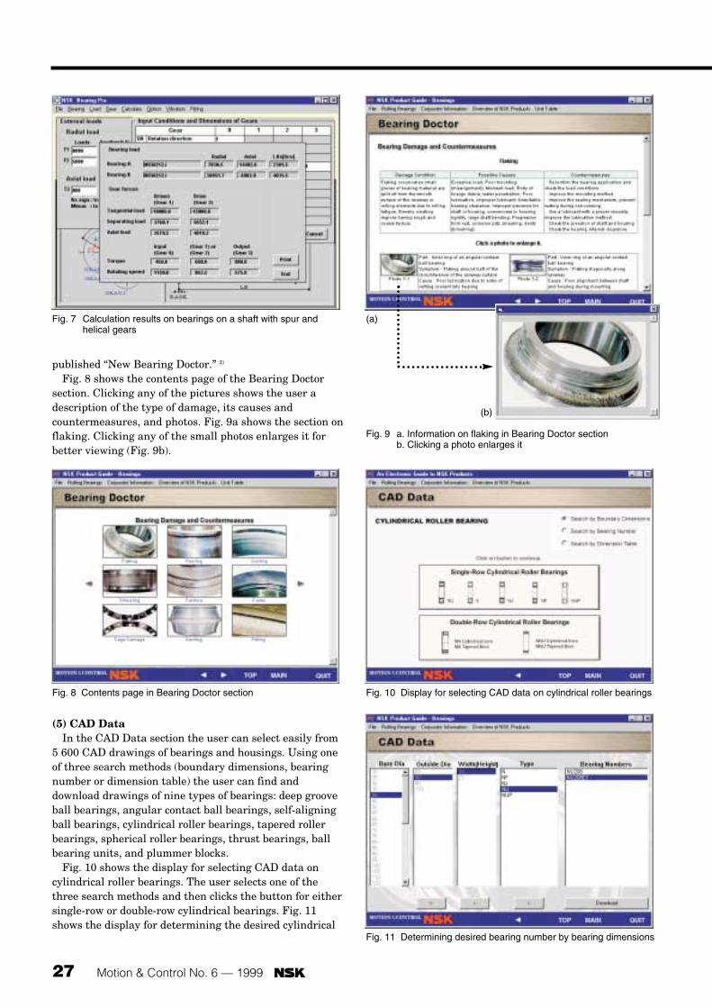
27 Motion & Control No. 6 — 1999
published “New Bearing Doctor.” 2)
Fig. 8 shows the contents page of the Bearing Doctorsection. Clicking any of the pictures shows the user adescription of the type of damage, its causes andcountermeasures, and photos. Fig. 9a shows the section onflaking. Clicking any of the small photos enlarges it forbetter viewing (Fig. 9b).
(5) CAD DataIn the CAD Data section the user can select easily from
5 600 CAD drawings of bearings and housings. Using oneof three search methods (boundary dimensions, bearingnumber or dimension table) the user can find anddownload drawings of nine types of bearings: deep grooveball bearings, angular contact ball bearings, self-aligningball bearings, cylindrical roller bearings, tapered rollerbearings, spherical roller bearings, thrust bearings, ballbearing units, and plummer blocks.
Fig. 10 shows the display for selecting CAD data oncylindrical roller bearings. The user selects one of thethree search methods and then clicks the button for eithersingle-row or double-row cylindrical bearings. Fig. 11shows the display for determining the desired cylindrical
Fig. 7 Calculation results on bearings on a shaft with spur andhelical gears
Fig. 8 Contents page in Bearing Doctor section Fig. 10 Display for selecting CAD data on cylindrical roller bearings
Fig. 11 Determining desired bearing number by bearing dimensions
Fig. 9 a. Information on flaking in Bearing Doctor sectionb. Clicking a photo enlarges it
(a)
(b)

Motion & Control No. 6 — 1999 28
roller bearing number based on boundary dimensions.After the desired bearing number is determined using theparameters of bore diameter, outside diameter, width(height), and type, the user can download the CAD data.
NOTE: To download and be able to utilize the CAD datain one’s personal computer, it is necessary to have DXFsoftware installed beforehand.
(6) Dimension TablesIn the Dimension Tables section, the user can look at the
boundary dimensions (bore diameter, outside diameter,width, and chamfer dimension), limiting speed, dynamicload rating, static load rating, abutment and filletdimensions, mass and other details of 10 types of bearings:deep groove ball bearings, small-diameter miniature ballbearings, angular contact ball bearings, self-aligning ballbearings, cylindrical roller bearings, tapered rollerbearings, spherical roller bearings, thrust bearings, ballbearing units and plummer blocks. Fig. 12 shows thedimension table for single-row cylindrical roller bearingsas an example.
2.4 Overview of ProductsPresenting information on bearings, automotive
components and precision and electronic products, thissection provides an overview of NSK products. Fig. 13shows part of the segment on automotive products.
2.5 Corporate InformationThis section provides basic information on NSK and
addresses and telephone numbers for NSK locationsaround the world.
3. Conclusion
We have presented here NSK’s new Product Guide forbearings. It will enable users to learn about thefundamentals of rolling bearings, obtain specificinformation on bearings, perform life and gearcalculations, and access CAD drawings. Considering the
opinions and needs of users, we will work to improve thisproduct and make it even easier for customers to use infuture editions.
References:1) NSK Rolling Bearing Catalog, CAT. No. E1101b2) NSK New Bearing Doctor, CAT. No. E7005
Fig. 12 Dimension table for single-row cylindrical roller bearings
Fig. 13 Automotive products section in “Overview of Products”
Yukio Hirata

29 Motion & Control No. 6 — 1999
1. Introduction
Progress in information technology devices has occurredat a dizzying pace and the widespread use of these deviceshas been truly remarkable. Personal computers are found
in businesses and homes throughout the world and itappears that improvements in their performance have noend in sight. At the same time, new software andperipheral devices are appearing on an almost daily basis.As for performance improvement of office automation
Sound and Vibration in Rolling BearingsTatsunobu Momono and Banda Noda Basic Technology Research and Development Center
ABSTRACTProgress in information technology devices and the proliferation of these devices throughout the world have occurred at
an astonishingly rapid pace. Not only have there been remarkable improvements in computers, automobiles and electrichome appliances, but the total number of such products owned and used by people has increased dramatically.
In the midst of such advancement, demand has grown for rolling bearings with lower vibration and noise. In response,extensive research and development has been undertaken at NSK.
This report summarizes some of the key findings accumulated from research on sound and vibration in bearings, anddiscusses vibration modes of bearing rings. In addition, a useful table summarizing sound and vibration in bearings isincluded as a convenient reference tool for the reader.
Sound Vibration Features
Race noise Free vibration of raceway ring Continuous noise, basic unavoidable noise which all bearings generate
Structural
Manufacturing
Click noiseFree vibration of raceway ring, free vibration of cage
Regular noise at a certain interval, large bearings and horizontal shaft, radial load and low rpm
Squeal noise Free vibration of raceway ringIntermittent or continuous, mostly large cylindrical roller bearings, radial load, grease lubrication, at particular speed
Cage noise
—
“CK” noise
“CG” noise
Tapping noise
Free vibration of cage Regular noise at a certain interval, all bearing types generate it
Vibration of cage Intermittent or continuous, lubrication with particular grease
Free vibration of cage Certain interval, but a little irregular under radial load and during initial stage
Rolling element passage vibration Continuous, all bearing types under radial load
Waviness noiseVibration due to waviness
Inner ring Continuous noise
Outer ring Continuous noise
Rolling element Continuous with rollers, occasional with balls
— Runout
fr Continuous
fc Continuous
fr - 2fc Continuous
Handling
Others
Flaw noiseVibration due to flaw
Inner ring
Regular noise at a certain interval
Contamination noise Vibration due to contamination Irregular
Seal noise Free vibration of seal Contact seal
Lubricant noise — Irregular
Outer ring
Rolling element
Table 1 Classification of sound and vibration in rolling bearings

Motion & Control No. 6 — 1999 30
equipment, particularly personal computers and relatedproducts, demand is high for ever-lower vibration andsound levels of moving components. In the automotive andhome appliance industries, performance improvementcontinues unabated and the average number of suchproducts owned by households increases steadily. Forconsumer goods such as air conditioners, washingmachines, refrigerators, vacuum cleaners andautomobiles, quietness is a key selling point that oftenhelps clinch sales.
Amid these market conditions, requirements for lowvibration and sound in rolling bearings become moresevere every year. At NSK, intensive R&D is beingundertaken to meet such requirements, particularly forsmall and ultra-small ball bearings. For example, resultsof research on low vibration and low noise in VCRbearings served as the foundation for NSK’s recentlydeveloped HDD bearings, which are acclaimed for theirworld-class quality. In this report, we discuss vibrationand sound in rolling bearings based on key findings frompast research.
2. Classification of Vibration andSound in Bearings
The various types of vibration and sound in rollingbearings are grouped into the four categories listed inTable 1.1) While other ways of classifying vibration andsound exist, the discussion in this report is based on theclassification system in this table. In this classificationsystem, the distinctions between the categories are notabsolute. For example, the magnitude of structural soundor vibration is partially related to the manufacturingprocess. When sound is generated, in most cases vibrationoccurs, and when vibration occurs, usually sound isgenerated. For example, when vibration is caused bywaviness, it is assumed that at the same time a “wavinesssound” is generated. While vibration and sound almostalways accompany each other, problems of vibration andsound are usually characterized in terms of one or theother. This is because the ability or inability of humans tohear sound or sense vibration depends on frequency. Low-frequency sound is barely audible while high-frequencyvibration cannot be perceived by humans. For this reason,problems at low frequency are “vibration problems,” and
Table 1 (continued)
fRiN , fM1 fAiN , fAM Selective resonance of waviness (rolling friction)Improve rigidity around the bearings, appropriate radial clearance, high-viscosity lubricant, high-quality bearings
Generated frequency (frequency analysis)
FFT of original wave FFT after envelope (basic No. )
Source CountermeasuresRadial(angular) direction
Axialdirection
—
fRiN , fM1 fAiN , fAMCollision of rolling elements with inner ring or cage Reduce radial clearance, apply preload, high-viscosity oilZfc
(≈ fR2N , fR3N) — Self-induced vibration caused by sliding friction at rolling surface
Reduce radial clearance, apply preload, change the grease, replace with countermeasured bearings?
Natural frequency of cage Collision of cage with rolling elements or rings Apply preload, high-viscosity lubricant, reduce mounting errorfcNatural frequency of cage Self-induced vibration caused by friction at cage guide surface Change the grease brand, replace with countermeasured cage?
Natural frequency of cage Collision of cage and rolling element caused by grease resistance
Reduce radial clearance, apply preload, low-viscosity lubricant
Zfc
Zfc —
nZfi ± fr (nZ ± 1 peaks)
nZfi (nZ peaks)
Displacement of inner ring due to rolling element passage Reduce radial clearance, apply preload—
Inner ring raceway waviness, irregularity of shaft exterior High-quality bearings, improve shaft accuracy—
nZfc (nZ ± 1 peaks)
nZfc (nZ peaks) Outer ring raceway waviness, irregular bore of housing High-quality bearings, improve housing bore accuracy—
2nfb ± fc (2n peaks)
2nfb (2n peaks)
Rolling element waviness High-quality bearings—
fr — Irregular inner ring cross-section High-quality bearings—
fc — Ball variation in bearing, rolling elements non-equidistant High-quality bearings—
fr - 2fc — Non-linear vibration due to rigid variation by ball variation High-quality bearings—
fRiN , fM1 fAiN , fAM
Nicks, dents, rust, flaking on inner ring raceway Replacement and careful bearing handlingZfi
fRiN , fM1 fAiN , fAM Entry of dirt and debris Washing, improve sealingIrregular
Natural frequency of seal Self-induced vibration due to friction at seal contact area Change the seal, change the grease(fr)
? ? Lubricant or lubricant bubbles crushed between rolling elements and raceways
Change the greaseIrregular
Nicks, dents, rust, flaking on outer ring raceway Replacement and careful bearing handlingZfcNicks, dents, rust, flaking on rolling elements Replacement and careful bearing handling2fb
Natural frequency of cage
n: Positive integer (1, 2, 3...)Z: Number of rolling elementsfRiN: Ring natural frequency in radial bending mode, HzfM1: Natural frequency in the mode of angular vibration in inertia of outer
ring-spring system, Hzfr: Rotation frequency of inner ring, Hz
fc: Orbital revolution frequency of rolling elements, HzfAiN: Ring natural frequency in axial bending mode, HzfAM: Natural frequency in the mode of axial vibration in mass of outer ring-spring
system, Hzfi: fi = fr - fc, Hzfb: Rotation frequency of rolling element around its center, Hz

31 Motion & Control No. 6 — 1999
those at high frequency are “noise problems.” As a rule ofthumb, the arbitrary border separating vibration problemsfrom noise problems is 1 000 Hz. In other words, below 1 000 Hz is considered to be vibration and above 1 000 Hzis sound or noise.
3. Types of Vibration and Sound in Bearings
3.1 Structural vibration and sound Even when the most advanced manufacturing
technology is used, vibration and sound still occurnaturally in rolling bearings. As such vibration and sounddo not degrade bearing performance, they are accepted asnormal bearing characteristics.
3.1.1 Race noise Race noise is the most basic sound in rolling bearings. It
is generated in all bearings and is a smooth andcontinuous sound. At NSK we say it sounds like “sha-ahh.”The magnitude of this sound is used to assess bearingquality. Fig. 1 shows how the magnitude of race noisecompares to familiar sounds.2) In this figure, even thesound generated by the loudest of the bearings, bearing#6410, is only about 1/100 of the magnitude of normalconversation. It is clear that the energy associated withrace noise is very limited. The characteristics of race noiseare as follows:3)
(1) The frequency of the sound does not change even whenrotational speed changes. Its frequency is the naturalfrequency of the raceway rings, as illustrated in Fig. 2.
(2) The faster the running speed, the louder the sound.(3) If radial clearance is reduced, the sound becomes
louder. (4) As for the lubricant, when its viscosity is higher the
sound is reduced. Besides the viscosity of the grease,the consistency, form and size of the soap fiber in italso affect noise performance.
(5) The higher the rigidity of the housing, the lower themagnitude of the sound.
Race noise is considered to be caused by configurationerror (called microundulation or waviness), which occurseven when the most advanced machining technology isused to process the surfaces of the raceways and rollingelements of a bearing. Due to this waviness, the contactbetween the raceway rings and rolling elements behaveslike a spring that fluctuates minutely during bearingoperation. The variation of this so-called spring acts as anexcitation force on the raceway rings of the bearing.Consequently, vibration and race noise are generated.
The generation of race noise is inevitable and there areno special countermeasures to eliminate it completely.However, it can be minimized by improving the overallquality and precision of bearings.
3.1.2 Click noiseClick noise tends to occur more often in relatively large
bearings under radial loads. It is generated only at lowspeeds, disappearing when speed exceeds a certain level. Arough approximation of this noise used at NSK is “katakata.” It is somewhat similar to flaw noise, which isdescribed in a following section. The generation of clicknoise is believed to proceed as follows (Fig. 3). When abearing is operated under a radial load, then a load zoneand no-load zone exist inside the bearing. The bearing hassome clearance in the no-load zone—rolling elements donot touch the inner ring, but do touch the outer ring due tocentrifugal force (Fc2). However, at low speeds, whencentrifugal force becomes less than the force of gravity(W1), the rolling elements fall and collide with the cageand/or inner ring. It is the collisions between the rolling
160
150
140
130
120
110
100
90
80
70
60
50
40
30
20
10
0
104
103
102
101
1
10-1
10-2
10-3
10-4
10-5
10-6
10-7
10-8
10-9
10-10
10-11
10-12
6410630662066203630362006000
Power level (dB) Sound output (watts)
Jet plane
Pneumatic hammer
Piano
Regular conversation
(Bearing)
Whispering
50
40
30
1 2 5 10
: 2 110 rpm: 1 770 rpm
: 1 560 rpm: 1 190 rpm: 1 010 rpm
Bearing: 6304Axial load: 19.6N
Sou
nd p
ress
ure
leve
l, dB
Frequency, kHz
Fig. 1 Loudness range of race noise
Fig. 2 Influence of rotation speed on race noise

Motion & Control No. 6 — 1999 32
elements and the cage and/or inner ring that generateclick noise.
Applying a preload is an effective countermeasure toclick noise. Reducing radial clearance results in only asmall improvement. Another remedy is using light rollingelements like those made of ceramic.
3.1.3 Squeal noiseSqueal noise is a metallic noise that can be rather loud
in some cases. It sounds like metal sliding on metal andwe express it in Japanese as “kyuru kyuru.” With squealnoise, bearing temperature does not generally rise andbearing and grease life are not adversely affected. In fact,beyond the noise problem (if indeed it is actually aproblem), there is no other hindrance to bearing operation.Squeal noise tends to occur with relatively large bearingsused under a radial load. It occurs frequently in cylindricalroller bearings, but may also occur in ball bearings. Thecharacteristics of squeal noise are:(1) It tends to occur when radial clearance is large.(2) It occurs mostly with grease lubrication and only rarely
with oil lubrication. (3) It occurs more often in winter. (4) It occurs within a certain speed range that tends to
become lower as bearing size increases. (5) Its generation is inconsistent and unpredictable, and
depends on the kind and amount of grease, as well asbearing operating conditions.
Influenced by the lubrication used and increasingvibration of the outer ring, the friction between the outerring and rolling elements is considered to be the cause ofsqueal noise. Squeal noise is attributed to self-inducedvibration related to lubrication. However, there is animportant question: From what part of the circumferenceof the outer ring is squeal noise emitted? The jury is stillout on this question as some experts believe the noise isgenerated in the load zone while others argue that it isgenerated in the no-load zone.4),5) Effectivecountermeasures to squeal noise include reducing theradial clearance and employing a very shallow groove inthe outer ring raceway of the bearing.6)
3.1.4 Cage noiseThere are two kinds of cage noise: a noise suggestive of
the cage colliding with rolling elements or bearing rings(“kacha-kacha” at NSK) and a low-frequency noise (“gagagaga”). NSK differentiates them by calling them “CKnoise” and “CG noise,” respectively. CK noise can begenerated in any type of bearing and the magnitude of it isusually not very high. Characteristics of this noise include: (1) It occurs with pressed steel cages, machined cages and
plastic cages.(2) It occurs with grease and oil lubrication.(3) It tends to occur if a moment load is applied to the
outer ring of a bearing.(4) It tends to occur more often with greater radial
clearance. CK noise is attributed to the rotating cage colliding with
rolling elements or raceway rings. As there is clearancebetween the cage and both the rolling elements andraceway rings, it is difficult to completely eliminate CKnoise. However, it can be reduced to some extent byreducing the mounting error.
(a) At low-speed rotation
(b) At high-speed rotation
Centrifugal force (Fc1)
Weight of rolling element (W1)
Centrifugal force (Fc2)
Weight of rolling element (W1)
Fr
Fr
Fc1 < W1
Fc2 > W1
Fig. 3 Mechanism of rolling element falling noise
+10
-10
0
+10
-10
0
Am
bien
t tem
pera
ture
, °C
Vib
ratio
n of
spi
ndle
(ac
cele
ratio
n)V
ibra
tion
of s
pind
le (
acce
lera
tion)
Am
bien
t tem
pera
ture
, °C
Ambient temperature
(a) Conventional bearings
(b) Bearings with countermeasure
Occurrence of CG noise
Vibration of spindle
Test time (approximately eight hours)
Test time (approximately eight hours)
Ambient temperature
Vibration of spindle
Fig. 4 Performance evaluation test of cage noise (CG noise)

33 Motion & Control No. 6 — 1999
CG noise is a special noise which, in Japan, is perceivedas being similar to a croaking frog. It is attributed to self-induced vibration of the cage caused by sliding frictionbetween the cage guide face and the bearing componentthat guides the cage. It frequently becomes loud andtherefore problematic. For this reason, a bearing wasspecially designed with the expressed purpose ofsuppressing cage noise of this type.7) Fig. 4 compares theperformance of a conventional bearing, to which nocountermeasure was applied, to a bearing with a speciallydesigned cage. The bearings were mounted on a spindle,and because CG noise tends to occur at lowertemperatures, ambient temperature was graduallylowered during the test. In the bearing with the speciallydesigned cage, cage noise did not occur even after theambient temperature went below 0°C. CG noise isgenerated with grease lubrication and tends to occur withrelatively hard grease. The use of the specially designedcage is effective in reducing CG noise, as is the carefulselection of lubricant.
When a bearing is used under a radial load with hardgrease, a loud cage noise (sounding roughly like “gachagacha”) may occur at the initial stage of rotation. Thisnoise is caused by the rolling elements colliding with the
cage as they suddenly decelerate due to grease resistanceafter departing the load zone. However, this noise becomesnegligible and eventually disappears with time.
3.1.5 Rolling element passage vibrationRolling element passage vibration becomes a problem
mostly in rolling bearings operating under a radial load.When this kind of vibration occurs, the shaft’s center ofrotation runs out both vertically and horizontally and anoise, which at NSK is expressed as “goro goro,” mayoccur. The amplitude of this vibration is influenced byradial clearance, radial load and the number of rollingelements. This type of vibration occurs due to variation inload sharing that depends both on the position of eachrolling element in the load zone and on the minutevariation in the amount and direction to which the shaft isdisplaced. Comparing conditions (a) and (b) in Fig. 5, thedisplacement of the rotating shaft in the vertical directionis slightly different. The shaft also moves transverselybetween the conditions shown in the figure. Theoreticaland experimental studies indicate that the frequency ofthis vibration can be expressed as:8)
f = Z · fc (Hz)
Z: Number of rolling elementsfc: Orbital revolution frequency of rolling elements (Hz)
As rolling element passage vibration is usually of smallamplitude, it rarely becomes a problem. When it doesbecome a problem, reduction of radial clearance orapplication of a preload can be effective countermeasures.
3.2 Vibration and sound related to bearingmanufacturing
Vibration and sound related to bearing manufacturing,the most significant type of which is caused by waviness,cannot be eliminated completely. Even with modern
11
2
2
3
3
44
55
6
6
7
7
8
8
(a) (b)
Fr Fr
Fig. 5 Mechanism of vibration due to rolling elements passing
1
1
1
11
1
22
2
22 2
3
33
3
3
3
4
4
4
44
4
55
5
5
6 66
6 6
7
7
7
7
77
8
8
8
(a) (b) (c)
(nZ-1) peaks n = 1
Z = 8
6
5
5
Fig. 6 Mechanism of vibration due to waviness of raceway or rolling element surface

Motion & Control No. 6 — 1999 34
precision machining technology, an element of wavinessexists that will generate sound and vibration albeit,however, at negligible levels. It is only when waviness isabnormal (due either to factors relating to manufacturingor a particular bearing’s application) that waviness noisebecomes a problem. Unlike most other sounds generatedby rolling bearings, the frequency of waviness noisedepends on the speed. This is an important characteristicby which waviness noise can be distinguished from othertypes of noise. At a constant rotational speed, wavinessnoise is harsh and has a constant frequency. At NSK wesay it sounds like “ooh ooh” or “whan whan.” When abearing is accelerating or decelerating, waviness noise iseven more harsh and its frequency increases or decreaseswith speed. NSK’s approximation of this noise is “hee-yun.” Waviness noise becomes a problem when thevibration caused by the waviness of the raceways and/orrolling elements is excessive.
Gustafsson conducted a basic study on vibration causedby waviness.9) He considered waviness in thecircumferential direction on the surface of the inner andouter ring raceways and rolling elements as a group ofsinusoidal waves. He examined the force balance insidethe bearing when such waviness exists and calculated thebearing vibration caused by it. As a result, he determinedthe number of waviness peaks that cause vibration andthe frequency of this vibration. The section of Table 1regarding the frequency of waviness noise reflects thesefindings. As it is clear from Table 1, waviness with aspecific number of peaks is the cause of this vibration. Asis shown in Fig. 6, vibration in the radial direction occurswhen waviness with (nZ-1) peaks exists on the inner ring.
Gustafsson’s analysis of vibration was based on aconstant axial load being applied and only one componenthaving waviness. Since his research, others have analyzed
cases where waviness existed on two components andradial load was applied.10), 11) According to these studies,vibration occurs with additional numbers of wavinesspeaks. While the generation of vibration and noise withthe number of peaks deduced by Gustafsson and shown inTable 1 has been confirmed in numerous cases, not enoughexperimental data have been gathered to confirm theadditional numbers of peaks in the more recent research.
To avoid problems, this vibration (waviness noise) can bereduced by decreasing the waviness in the circumferentialdirection on the finished surfaces of the bearingcomponents. Additionally, it should be noted that ifwaviness exists on the fitting face of the shaft or housing towhich the bearing is mounted, then this waviness reflectsonto the raceway surface of the bearing and generatesvibration. If a spline is cut on the shaft, a similar effect mayresult. Therefore, careful attention is required.
3.3 Vibration and sound due to improper handling
Major components of a bearing have a harder surfacethan HRC60, so they are usually tough. But if a bearing isdropped or otherwise sustains a shock, dents can result onthe finished surfaces of the bearing components. Even aslight defect in shape may cause vibration or sound. Inaddition to dents and flaws, minute contamination maycause problems. Vibration and sound in this group aremainly caused by improper handling of the bearing.
3.3.1 Flaw noiseWhen a flaw such as a dent or rust exists on a finished
raceway surface of a rolling bearing, then a pulsating,machine-gun-like noise is generated when the bearingrotates. At NSK this noise is expressed as “beee.” It iscaused by the rolling elements hitting the flaw on theraceway surface and is called flaw noise. As Table 1 shows,its frequency is the same as that of race noise. When flawnoise is generated, the level of the entire frequencyspectrum rises. As a result, analyzing the frequencysimply by FFT is not sufficient to distinguish it from someother noises. Flaw noise has unique generation cycles orintervals when compared to other types of noise (Fig. 7).At a constant speed, the noise generation cycle is constant,but as the speed decreases, the noise generation cyclebecomes longer. This cycle is determined by speed and theinternal specifications of the bearing. As Table 1 shows, italso changes with the position of the flaw on the bearing.12)
Due to this characteristic, it is possible to determinewhether flaws exist and if so, where they are located. Todetermine the generation cycle of such a noise, a methodcalled envelope analysis is used.
In the case of a ball bearing with a flaw on a ball, butnot necessarily on the rolling surface of the ball, noise dueto the flaw sometimes occurs and sometimes does not.When such noise is generated, it will always have a cycliccharacteristic.
When grease of high viscosity is used, the noise ismasked and the level of the noise tends to be reduced.
T T T T T T
T1
T1
T2
T2
T3
T3≠≠
(a) Normal
(b) Flaw noise
(c) Contamination noise
Time
Fig. 7 Waveform of noise due to flaw and contamination

35 Motion & Control No. 6 — 1999
However, when noise due to a flaw on a rolling elementoccurs, usually the bearing should be replaced.
3.3.2 Contamination noise The ingress of foreign particles into a bearing, either
from improper handling or severe operating conditions,results in contamination noise, which at NSK isapproximated by “chi chi chi.” It results from foreignparticles being caught between the rolling elements andraceway surfaces. The magnitude of contamination noiseis not constant and its generation is irregular (Fig. 7).Generally, the smaller the bearing, the larger theinfluence of foreign particles. Contamination noisefrequently is a problem with small-size or extra-small-sizebearings. The entry of foreign particles not only causesnoise but can also cause dents on the rolling surfaces ofthe bearing and thereby shorten bearing life. For thisreason, preventive measures must be taken.
3.4 Other vibration and soundThe various types of sound and vibration in Table 1 that
have been described to this point are fairly wellunderstood. However, the types of sound and vibration inthe category titled “Others” are not as well understood.The first of these is seal noise. In a grease-lubricatedbearing with contact seals, a “peee” noise may occur. Thisnoise is attributed to self-induced vibration caused byfriction between the seals and seal contact points. As acountermeasure, a different kind of seal or grease can beadopted.
During the initial rotation of a bearing with greaselubrication, noises that are roughly equivalent to “pee-shee” or “jyuu” may be heard. These noises are believed tobe generated when lubricant or lubricant bubbles arecrushed between the rolling elements and raceways. Theirgeneration is irregular and ceases as running timeelapses. This type of noise is not considered to be asignificant problem as its magnitude is low.
Next we discuss three types of vibration in rollingbearings: the fr, fc and fr-2fc vibration components. The fr
component is runout that is caused by an unbalanced shaftor uneven thickness of the inner ring. The frequency ofthis vibration is the same as the rotation frequency. The fc
component occurs if there is a difference in the diametersof the rolling elements or if the arrangement of the rollingelements is not equidistant. The frequency of thiscomponent is the same as the orbital revolution frequencyof the rolling elements.13) The fr-2fc component occurs whena difference in the diameters of the rolling elements affectsthe spring characteristics of the shaft and bearing. It hasbeen pointed out that this directional characteristicrotates at fc, and the frequency of this vibration is the fr-2fc frequency.13) For all of these vibration components,similar to vibration caused by waviness, the frequencyvaries as rotational speed changes. Waviness, fc and fr-2fc
vibration all are components of non-repetitive runout(NRRO) and as such are important topics in HDD researchand development.
4. Frequency of Vibration and Sound in Bearings
4.1 Natural frequency of raceway rings As can be understood from Table 1, many frequencies of
vibration and sound generated in bearings are related tothe natural frequency of the raceway rings. Of the tworaceway rings, the natural frequency of the outer ringbecomes a problem more often than the inner ring due to aloose fit between it and the housing. The modes ofvibration of the outer ring are roughly divided into twocategories: those that consider the outer ring as a rigidbody and those that consider it as an elastic body.3) Besidesthese, there are modes of vibration associated with eachbearing component such as the cage. However, thesevibrations have not been systematically studied yet due tothe complexity of the modes of vibration and the number offactors involved including shape, material and othervariables.
4.1.1 Rigid body modesFor a rigid body, there are two modes of vibration which,
for the sake of clarity, we will call mode A and mode B.Mode A is angular vibration in the inertia outer ring-spring system, and mode B is vibration in the mass outer
Fa
Fa Fa
Fa
kθ
J
Fa
Fa Fa ka
Fa
M
Fig. 9 Mode of axial vibration in mass of outer ring-spring system
Fig. 8 Mode of angular vibration in inertia of outer ring-spring system

Motion & Control No. 6 — 1999 36
ring-spring system. Mode A is illustrated in Fig. 8. Mode Bcan be divided further into radial and axial vibration, butbecause radial vibration rarely becomes a problem, onlythe mode of axial vibration is analyzed. So, mode B is thevibration in the system of the mass of the outer ring andspring in the axial direction of the bearing. It is illustratedin Fig. 9. To find the natural frequency, one needs todetermine the spring coefficient of a bearing, which takesa long time. Fortunately, for ball bearings to which a pureaxial load is applied, there is a formula which allowsnatural frequency to be calculated easily.14)
4.1.2 Elastic body modesAn example of a vibration mode in which the outer
raceway ring is considered as an elastic body is thebending mode. This vibration mode is divided into radialand axial modes, as shown in Fig. 10. In these vibrationmodes, the outer ring becomes a problem more frequently.There are several formulas for calculating the naturalfrequency of the bending mode in the outer ring of a ballbearing.15), 16), 17) These formulas give the value of thenatural frequency when a bearing is free, which for mostapplications is sufficiently accurate. When higher degreesof accuracy are required, a more complicated method ofcalculation that takes into account mounting conditionsmust be used.
4.2 Rotation frequency of rolling elementsAs is apparent from Table 1, in order to calculate either
the frequency of vibration caused by waviness or theenvelope frequency of flaw noise, the orbital revolutionfrequency of the rolling elements (fc) and the rolling
element frequency (fb) are required. These values aredetermined by the internal specifications of a bearing andthe running speed. They can be calculated with thefollowing formulas:3)
fc: Orbital revolution frequency of rolling elements (Hz)fb: Rotation frequency of rolling elements (Hz)ni: Running speed of inner ring (rpm)Da: Diameter of rolling elements (mm)dm: PCD of rolling elements (mm)a: Contact angle (°)
5. Conclusion
We have presented here a summary of the types ofvibration and sound in rolling bearings. Among thedifferent kinds of sound and vibration in Table 1, most ofthem are fairly well understood and the countermeasuresexplained in this report can be employed to control themwhen they are deemed excessive. There are still, however,some that are as yet not completely understood. Researchis ongoing at NSK in these areas. In any case, it should beunderstood that, due to the fundamental nature of rollingbearings and limitations on machining technology, acertain degree of vibration and sound is unavoidable.
Vibration and sound generated by rolling bearings isrelatively low compared to other machine components.Nevertheless, some customers still request reduced noise.This indicates the pivotal role bearings play in controllingnoise generated by machines and probably stems from thefact that sound and vibration can be transmitted frombearings to other parts of a machine and amplified there.For this reason, continued research, not only on bearings,but on their surrounding structures as well, is required.
References:1)* Noda, “Noise of Rolling Bearings,” J. JHPS, 17-7 (1986) 507-
5132)* Igarashi, Noda, “Sound of Ball Bearings,” NSK Bearing
Journal, 635 (1974) 8-173)* Ueno, et al, “Rolling Bearing Engineering,” Yokendo Ltd.
(1975) 139, 1014)* Kobayashi, “Grease Effect on Rolling Bearing Sound,” J.
JSLE, 19-4 (1974) 306-3205)* Nakai, Yokoi, et al, “Squeal Noise of Cylindrical Roller
Bearings,” Trans. JSME, C, 56-525 (1990) 1224-1252, 1253-1259
6)* New Product Introduction, “Cylindrical Roller Bearings forElectric Motors with Squeal Noise Countermeasures,NU300U Series,” NSK Bearing Journal, 623 (1969) 62
7)* Fujii, “Bearings for Computer Magnetic Disk Spindles,” NSK
(a) Radial mode (b) Axial mode
Primary
Secondary
Primary
Secondary
Fig. 10 Mode shapes for bearing rings (bending mode)
fc = 160
ni
2
dm – Da · cosαdm
·
fb = 160
–ni
2
dm
Da
Da · cos2αdm
· –

37 Motion & Control No. 6 — 1999
Bearing Journal, 644 (1984) 14-238)* Tamura, et al, “Static Running Accuracy of Ball Bearings,”
Trans. JSME, C, 52-475 (1986) 851-8589) O. Gustafsson, “Study of the Vibration Characteristics of
Bearings,” SKF Report, AL 62 L 005 (1962)10) F. P. Wardle, “Vibration Forces Produced by Waviness of the
Rolling Surfaces of Thrust Loaded Ball Bearings,” Proc. IME,202-C5 (1988) 305-312, 313-319
11) E. Yhland, “A Linear Theory of Vibrations Caused by BallBearings with Form Errors Operating at Moderate Speed,”Trans. ASME, J. Tribol., 113-April (1992) 348-359
12)* Kobayashi, Hashimoto, Gotou, “Problems on Rolling BearingSound and Vibration (Part 1),” Science of Machines, 20-1(1968) 19-24
13)* Yamamoto, “Critical Speed of Ball Bearings RegardingDimensional Errors,” Trans. JSME, 20-99 (1954) 750-755,755-760
14)* NSK Report No. 457, “Natural Frequency of Bearing Rings(Solid Mode),” Science of Machines, 47-4 (1995) 50
15)* Taniguchi, Endou, “Calculation Method of Annular Ring Vibration,” Science of Machines, 24-2 (1972) 271-275
16)* NSK Report No. 337, “Natural Frequency of IndividualBearing Rings (Part 1),” Science of Machines, 37-4 (1985) 52
17)* NSK Report No. 338, “Natural Frequency of IndividualBearing Rings (Part 2),” Science of Machines, 37-5 (1985) 56
* In Japanese
Tatsunobu Momono
Banda Noda

Motion & Control No. 6 — 1999 38
NSK has recently developed lightweight and low-costTKZ self-centering clutch release bearings with resinsleeves (Fig. 1). The mass-production of these bearingsbegan in autumn 1998. Without compromisingperformance or quality, we have been able to drasticallyreduce the price and weight of these new bearings.
Half the weight and much more economical thanexisting clutch release bearings with resin sleeves, TKZbearings can be used in new designs and as replacementsfor the existing five types of NSK clutch release bearings.The existing five types are:
TKA: Plastic ring method with iron sleeveTKB: Spring method with resin sleeveTKT: Spring method with resin sleeveTKE: Spring method with iron sleeveTKC: Spring method with separated sleeve
Features
� Long lifeDurability exceeds two million clutch release strokes(equivalent to 200 000 km)
� Low torqueResulting from light-contact seals
� Low noiseLess than 55 dB when new
� No lubrication necessary between sleeve andshaft
As wear of even aluminum shafts is eliminated by the newNSK-developed resin sleeve, no lubricant is requiredbetween the sleeve and shaft.
Available Sizes
New Products
Lightweight, Low-Cost TKZ ClutchRelease Bearings
A
B
Resin sleeve
Cross-section AOB
0
Fig. 1 TKZ clutch release bearing
Contact diameter Bore Assembled width
Small-size cars 44 28 20
Medium-size cars 50 33 22
SUVs 54 36 24
φ φφ φ
φ φ

39 Motion & Control No. 6 — 1999
Conventional washing machines generally use twostandard deep groove ball bearings and a one-way (roller)clutch, as shown in Fig. 1. Recently, compact componentsare required in order to free more space for higher-capacity washing tanks. To meet this requirement, NSKhas developed Cam-In Bearings™, compact and quietbearings with built-in one-way clutches.
Structure
The new bearing is shown in Photo 1. It is very compact,including a one-way clutch within the boundarydimensions of standard deep groove ball bearing number6205. The one-way clutch uses unique cams, which have atough cross-sectional profile, to withstand heavy loads andshocks. The specially designed one-piece cage holds thecams and steel balls securely in place.
Features
� Compact designAs Cam-in Bearings have the same dimensions (bore: φ25 mm × outside diameter: φ52 mm × width: 15mm) as standard deep groove ball bearing number 6205,space is freed to allow greater flexibility in product designand more space for higher-capacity washing tanks.
� Excellent torque characteristicsResulting from the tough specially designed cams, thetransmitting torque is high. The maximum transmittingtorque is nearly eight times the rated torque.
� Low noiseThe one-piece cage, which holds the cams securely inplace, and the garter spring ensure quiet running.
� High sealing performanceWith shields fitted on both sides, excellent sealing is achieved.
Performance
� Wedging life testTest conditions:
Test result: No abnormality after 1 million cycles
� Maximum transmitting torqueTest conditions:
Test result: Maximum transmitting torque = 343 N·m (35 kgf·m)
� NoiseThrough testing of actual washing machines, we confirmedthat noise was minimal during the spin cycle (i.e., whilerotating in the unlocked direction).
� Torque while rotating in the unlocked direction Test conditions:
Test result: Less than 4.9 N·m (500 gf·m)
Applications
Cam-In Bearings are now being mass-produced forwashing machines. They are also suitable for one-way-rotating electric motors and material-handling andconveying equipment.
New Products
Cam-In Bearings™—Bearings with Built-In One-Way Clutches
950 rpm
6205
6204
Pulley
Spring clutch
Wash basket
Band brake
Roller clutch
Drivingmotor
Fig. 1 Interior structure of conventional washing machine
Photo 1 Cam-In Bearings™
Load torque 42.1 N·m (4.3 kgf·m)
Number of wedging cycles 1 million
Ambient temperature Room temperature (25°C)
Ambient temperature Room temperature (25°C)
Measuring methodIncrease static torque and measure the maximum transmitting torque
Speed 1 000 rpm
Axial load 29.4 N (3 kgf)
Ambient temperature Room temperature (25°C)

Motion & Control No. 6 — 1999 40
New Products
Maintenance-Free Precision MachineryProducts with NSK K1™ Lubrication Units
A key developmental objective for rolling products ismaintaining effective lubrication while extendingmaintenance intervals. Towards this end, NSK developed“Molded Oil” and used it to create NSK K1™ lubricationunits for the various linear motion rolling products used intoday’s machines. Containing approximately 70 wt%lubricating oil, NSK K1 supply oil to rolling surfaces overan extended period of time. Since arriving on the marketin early 1996, they have been well received for prolongingmaintenance intervals and reducing costs. Now NSK hascreated the Maintenance-Free Series, a standardized lineof products equipped with NSK K1. We are pleased topresent it in this article.
The Maintenance-Free Series and Its Benefits
Figs. 1 through 5 illustrate the construction of the NSKLinear Guides, Ball Screws, Monocarriers, Robot Modulesand Megathrust Motors in the Maintenance-Free Series.The installation of NSK K1 in these products provides thefollowing benefits:
� Extended maintenance-free intervalsWhen grease is used in combination with NSK K1,lubricating efficiency is retained over a longer period oftime than existing products. For machines and equipmentthat are not easily supplied with lubricant, this isespecially advantageous.
� No contamination of surrounding environment As products in the Maintenance-Free Series can beeffectively lubricated with only a small amount of grease,they not only contribute to a cleaner environment but arealso well suited to applications where contamination from oil must be prevented due to high cleanlinessrequirements.
� Prolonged service life when products are exposed to water
In operating environments in which the products areexposed to water, either from the equipment they operatein being washed or from exposure to wind and rain, NSKK1, in combination with grease, prolong the service life.
� Better performance in contaminating environmentsEven in environments where the entry of foreign particlesis unavoidable, the combination of NSK K1 and greaseprovides effective lubrication for a longer period of timeand minimizes damage.
Conclusion
The market for linear motion products has long beendemanding products that reduce maintenance time andcosts. The Maintenance-Free Series, with its array ofproven products, responds well to this demand. We are confident that it will contribute substantially toreducing maintenance and costs, as well as improving the environment.
Ball nut
K1 cap
Labyrinth seal
Garter spring
Shaft
NSK K1™
Ball slide
Tightening ring
End cap
Protector
Rail
End seal
NSK K1™
Fig. 1 Maintenance-Free Series NSK Linear Guide
Fig. 2 Maintenance-Free Series Ball Screw

41 Motion & Control No. 6 — 1999
End seal
SliderProtector
Screw shaft
NSK K1™
Slider
Ball screw
Motor
NSK Linear Guide
NSK K1™
NSK K1™
Rack baseNSK Linear Guide
Slider
NSK K1™
Fig. 3 Maintenance-Free Series Monocarrier
Fig. 5 Maintenance-Free Series Megathrust Motor
Fig. 4 Maintenance-Free Series Robot Module

Motion & Control No. 6 — 1999 42
MEMO
.................................................................................................................
.................................................................................................................
.................................................................................................................
.................................................................................................................
.................................................................................................................
.................................................................................................................
.................................................................................................................
.................................................................................................................
.................................................................................................................
.................................................................................................................
.................................................................................................................
.................................................................................................................
.................................................................................................................
.................................................................................................................
.................................................................................................................
.................................................................................................................
.................................................................................................................
.................................................................................................................
.................................................................................................................
.................................................................................................................
.................................................................................................................
.................................................................................................................
.................................................................................................................
.................................................................................................................
.................................................................................................................
.................................................................................................................
.................................................................................................................
.................................................................................................................

43 Motion & Control No. 6 — 1999
MEMO
.................................................................................................................
.................................................................................................................
.................................................................................................................
.................................................................................................................
.................................................................................................................
.................................................................................................................
.................................................................................................................
.................................................................................................................
.................................................................................................................
.................................................................................................................
.................................................................................................................
.................................................................................................................
.................................................................................................................
.................................................................................................................
.................................................................................................................
.................................................................................................................
.................................................................................................................
.................................................................................................................
.................................................................................................................
.................................................................................................................
.................................................................................................................
.................................................................................................................
.................................................................................................................
.................................................................................................................
.................................................................................................................
.................................................................................................................
.................................................................................................................
.................................................................................................................