caterpillar engine 01 - american lafrance aftermarket ... · oil pressure connection, 1/4- ......
TRANSCRIPT

Engine Port DiagramsUse the following diagrams to identify engine ports:
• For a Caterpillar CFE engine, see Fig. 1 .
• For a Caterpillar C-7/C-9 and C-11/C-13 en-gine, see Fig. 2 .
• For a Caterpillar C-10/C-12 engine, see Fig. 3 .
08/31/2000
12
34
5
67
8
8
9
10
11 12
13
14
16
17
15 15
1518
19
20
f011848
21
1. Oil Pressure Connection, 1/4-Inch NPT
2. Oil Return, 9/16–183. Oil Pan, 1-1/16–124. Oil Drain, 3/4–165. Magnetic Pick-Up6. Fuel Inlet, 9/16–187. Fuel Return, 9/16–188. Ether Start Ports
9. Vent-to-Radiator, 3/8-Inch NPT10. Water Outlet11. Water Temperature Gauge
Connection, 1/2-Inch NPT12. Water Temperature Alarm
Connection, 1/2-Inch NPT13. Water Temperature, 1/2-Inch
NPT14. Water Supply, 1-1/16–12
15. Water Drain, M1216. Cab Heat Supply, 1-1/16–1217. Water Temperature, 3/4-Inch
NPT18. Radiator Shunt Line Connection19. Water Return Line, 3/4-Inch NPT20. Water Inlet, 51 mm21. Oil Drain
Fig. 1, Caterpillar CFE Engine Ports
Caterpillar Engine 01.00Engine Port Diagrams
Condor Workshop Manual, Supplement 7, September 2005 050/1

f012076a05/13/2005
1 12
345
6
7
8
9 10
11
12
1314
15
910
1617
18
19
20
21
2122
23 24 25
26
2728
29303132
33
11
9
78
28
2127
26
2524
20
19
18
1. Lube Heater Inlet, 1-5/16 x 12(No. 16 Port)
2. Oil Drain, 1-1/8 x 123. Bypass Oil Supply, 9/16-18 (No.
16 Port)4. Bypass Oil Filter Mounting5. Oil Pressure Connection, 9/16-18
(No. 6 Port)6. Block Heater Mounting, 1-5/16 x
12 (No. 16 Port)7. Live Oil Sample Location,
9/16-18 (No. 6 Port)8. Turbocharger Exhaust Outlet9. Cab Heater Supply, 1-1/16 x 12
(No. 10 Port)
10. Turbocharge Air Inlet11. Water Outlet, 2.5" (63.5 mm) OD12. Air Outlet (to Aftercooler)13. Cab Heater Return, 7/8-14 (No.
10 Port)14. Water Drain, 7/8-14 (No. 10 Port)15. Water Inlet, 2.5" (63.5 mm) OD16. Air Inlet (from Aftercooler)17. Air Compressor Water Return18. Air Outlet-Air Compressor 1/2
STD Pipe19. Live Oil Sample Location, 9/16 x
18 (No. 6 Port)20. Fuel Inlet, 7/8-14 x 45° Flare21. Starting Mounting Pad
22. Oil Drain, 1-1/18 x 1223. Air Compressor Water Supply24. Oil Level Gauge25. Air Inlet (from Aftercooler)26. Fuel Return, 5/8-18 x 45° Flare27. Electrical Ground Connection,
M10 x 1.5 x 30.4 LG28. Electrical Control Module29. Magnetic Pick-Up30. Fuel Bleed31. Fumes Disposal Tube, 1.25"
(31.8 mm) OD32. Hydraulic Drive Location33. Bypass Oil Return, 1-5/16 (No.
16 Port)
Fig. 2, Caterpillar C-7/C-9 Engine Ports (C-11/C-13 similar)
Caterpillar Engine01.00Engine Port Diagrams
Condor Workshop Manual, Supplement 7, September 2005050/2

09/14/2000
1
2
3
54
6
9
9
17
181211
10
19
1312 11
7 8
16
14
14
15
f011892
1. Water Supply, 1/2 NPT2. Water Inlet3. Water Return, 1/2 NPT4. Oil, 1/8 NPT5. Water Drain, 3/8 NPT6. Oil Pan Connection, 1/2 NPT7. Water Outlet
8. Water Return, 3/4 NPT9. Fuel Return, 5/8-1810. Oil Connection, 1 NPT11. Magnetic Pick-Up12. Fuel Inlet, 7/8-1413. Oil Pressure Connection, 9/16-18
14. Air Manifold Port, 1/4 NPT15. Air Manifold Port, 9/16-1816. Water, 1/2 NPT17. Engine Block Heater18. Oil Drain, 1-1/8 –1219. Vent to Radiator, 3/8 NPT
Fig. 3, Caterpillar C-10/C-12 Engine Ports
Caterpillar Engine 01.00Engine Port Diagrams
Condor Workshop Manual, Supplement 7, September 2005 050/3

Inspection1. Inspect all used drive belts (including those that
are being replaced) for the following conditionssee (Fig. 1 ):
1.1 Inspect for glazing (shiny sidewalls). Glaz-ing is caused by friction created when aloose belt slips in the pulleys. It can alsobe caused by oil or grease on the pulleys.
1.2 Inspect for separating layers. Oil, grease,or belt dressings can cause the belt to fallapart in layers. If engine parts are leaking,repair the oil leaks. Do not use belt dress-ings on any belt.
NOTE: For an installed belt, gently twist thebelt about 90 degrees so you can see thesidewalls and bottom.
1.3 Check for jagged or streaked sidewalls.These are the result of a foreign object(such as sand or small gravel) in the pul-ley, or a rough pulley wall surface.
1.4 Check for tensile breaks (breaks in thecord body). Cuts in a belt are usuallycaused by large foreign objects in the pul-ley, or by prying or forcing the belt duringinstallation or removal.
1.5 On poly-V belts, check for uneven ribs.Foreign objects in the pulley will erode theundercord ribs, causing the belt to lose itsgripping power.
IMPORTANT: Replacing only one belt of amatched set will cause the new belt to carrymore load, due to previous stretching in theolder belt. This additional load can cause thenew belt to break.
1.6 Replace the belt if any of the above condi-tions are found. Replace both belts of aset (if applicable), at the same time.Matched belts must be from the samemanufacturer.
Inspect for cracks, see (Fig. 2 ). Small,irregular cracks are usually signs of an oldbelt.
2. Check all pulley bearings for roughness. Replacethe bearings if they’re rough.
3. Inspect all pulleys for foreign objects, oil, orgrease in the grooves. Use a nonflammablecleaning solvent to remove oils. Use a wire brushto remove rust, and a file to remove burrs.
4. Inspect the pulleys for wear on the inner walls.Hold a small straightedge against the inside ofthe pulley walls see (Fig. 3 ), or use your littlefinger or fingernail to find grooves in the innerwalls. If there are any grooves, replace the pul-ley.
5. Check alignment of pulleys. Use a thin straight-edge that is longer than the longest span be-tween the pulleys. Place the straightedge into theV-grooves of two pulleys at a time. The straight-edge should be parallel to the outer edges of thepulleys; if not, the pulleys are misaligned.
Pulley misalignment must not be more than 1/16-inch for each foot (1.5 mm for each 30.5 cm) ofdistance between pulley centers.
If there is misalignment of the pulleys, adjust thepulleys or brackets if their positions are adjust-able. See Fig. 4 . Replace bent or broken pulleys,pulley brackets, or shafts.
6. Check all drive component mounting parts forloose fasteners, cracks, or other damage.Tighten loose fasteners. Repair or replacecracked or damaged brackets.
Caterpillar Engine 01.00Pulley and Drive Belt Inspection, Caterpillar
Engines
Condor Workshop Manual, Supplement 7, September 2005 100/1

f150010a
A
B
C
D
E
F11/21/94
A. GlazingB. Separating Layers
C. Streaked SidewallsD. Tensile Break
E. Uneven RibsF. Cracks
Fig. 1, Drive Belt Problems
11/08/94 f010876
A
B
A. Cracks Normal, Belt OkayB. Cracks not Normal, Replace Belt
Fig. 2, Check for Cracks
f150011a06/23/94
1
2
1. Groove in Pulley Wall2. Small Straightedge
Fig. 3, Check for Pulley Wear
Caterpillar Engine01.00Pulley and Drive Belt Inspection, CaterpillarEngines
Condor Workshop Manual, Supplement 7, September 2005100/2

f150012a06/23/94
A
A. Side View of Misaligned Pulleys.
Fig. 4, Check for Misaligned Pulleys
Caterpillar Engine 01.00Pulley and Drive Belt Inspection, Caterpillar
Engines
Condor Workshop Manual, Supplement 7, September 2005 100/3

Belt Replacement (See Fig. 1)
Fan and Alternator Belt1. Remove the belt.
1.1 Remove the belt from the refrigerant com-pressor pulley and let the belt rest on thefan hub. Refer to the refrigerant compres-sor belt removal procedure in this subject.
1.2 Insert a 1/2-inch breaker bar in the belttensioner and rotate the tensioner downand off the belt.
1.3 Holding the belt tensioner down, removethe belt from the alternator pulley.
1.4 Slowly release the belt tensioner, and re-move the breaker bar.
1.5 Lower the belt, and take it off the vibra-tion damper. Raise the belt, and take it offover the fan. Remove the belt from theengine compartment.
2. Install the belt.
09/13/2000 f200543
1
2
3
4
5
6
7
8
9
1. Vibration Damper2. Idler Pulley3. Alternator Belt Tensioner4. Alternator Pulley
5. Fan Pulley6. Refrigerant Compressor Belt
Tensioner
7. Refrigerant Compressor8. Refrigerant Compressor Belt9. Alternator Belt
Fig. 1, Drive Belts, Caterpillar C-10/C-12 Engines
Caterpillar Engine 01.00Drive Belt Replacement, Caterpillar C-10/C-12
Condor Workshop Manual, Supplement 0, January 2000 110/1

2.1 Inspect the pulleys and used belts (evenif installing new belts) as instructed inSubject 100 .
2.2 If the fan or fan hub was removed to re-move the compressor belt, install the fanor fan hub with the compressor belt in thefan pulley groove. Do not attach the com-pressor belt to the compressor at thistime.
2.3 Loop the fan/alternator belt around thefan and align it in the rear channel of thefan pulley.
2.4 Loop the belt down and around the vibra-tion damper pulley.
2.5 Install the refrigerant compressor belt onthe compressor. Refer to the refrigerantcompressor belt installation instructions inthis subject.
2.6 Insert a 1/2-inch breaker bar in the belttensioner, and rotate the tensioner downwhile installing the belt on the alternatorpulley.
2.7 Slowly release the tensioner assemblyonto the belt. The tensioner automaticallytightens the belt to the correct tension.
2.8 Remove the breaker bar from the ten-sioner.
3. Adjust the belt tension.
3.1 The Caterpillar belt tensioner automati-cally adjusts the fan and alternator belt tothe correct tension.
3.2 If the belt slips, repair or replace the ten-sioner. For instructions, refer to the Cater-pillar C-10/C-12 Truck Engine ServiceManual.
Refrigerant Compressor Belt1. Remove the belt.
NOTE: The pulley bolt has left-handedthreads.
1.1 Use a 15-mm socket on the bolt and ro-tate the tensioner counterclockwise.
1.2 Holding the belt tensioner up, remove thebelt from the compressor pulley.
1.3 Slowly release the belt tensioner, and re-move the socket.
1.4 Remove the compressor belt from the fanpulley. If necessary, remove the fan fromthe fan pulley according to the instruc-tions in Section 20.01 , Subject 110.
2. Install the belt.
2.1 Inspect the pulleys and used belts (evenif installing new belts) as instructed inSubject 100 .
2.2 Install the belt around the fan pulley.
2.3 If the fan was removed, install it accord-ing to the instructions in Section 20.01 ,Subject 110.
2.4 Use a 15-mm socket on the bolt and ro-tate the tensioner counterclockwise whileinstalling the belt on the compressor pul-ley.
2.5 Slowly release the tensioner assemblyonto the belt. The tensioner automaticallytightens the belt to the correct tension.
2.6 Remove the socket from the tensioner.
3. Adjust the belt tension.
3.1 The Caterpillar belt tensioner automati-cally adjusts the fan and alternator belt tothe correct tension.
3.2 If the belt slips, repair or replace the ten-sioner. For instructions, refer to the Cater-pillar C-10/C-12 Truck Engine ServiceManual.
Caterpillar Engine01.00Drive Belt Replacement, Caterpillar C-10/C-12
Condor Workshop Manual, Supplement 0, January 2000110/2

Replacement1. Insert a 1/2-inch rachet drive into the square hole
in the belt tensioner, and turn the tensioner downand off the belt. See Fig. 1 .
2. Remove the engine accessory drive belt.
3. Inspect the pulleys and the drive belt, even if in-stalling a new belt, as instructed in Subject 100 .
CAUTIONWhen installing a serpentine accessory drivebelt, route the belt correctly. If the belt is not
routed correctly, the water pump pulley may ro-tate in the wrong direction, allowing the engine tooverheat.
4. Position the drive belt over all the pulleys except
the drive belt tensioner. For the correct belt rout-ing, see Fig. 1 .
5. Insert a 1/2-inch rachet drive into the square holein the belt tensioner, and turn the tensionerclockwise. See Fig. 1 .
6. Position the tensioner against the belt, and re-move the rachet drive from the tensioner.
08/24/2000 f200540
12
3
4
5
6
7
1. Fan Clutch2. Idler Pulley3. Alternator
4. Refrigerant Compressor5. Fan Shroud
6. Belt Tensioner7. Drive Belt
Fig. 1, Caterpillar 3126/CFE Engine
Caterpillar Engine 01.00Drive Belt Replacement, Caterpillar 3126/CFE
Condor Workshop Manual, Supplement 0, January 2000 120/1

Removal1. Park the vehicle on a level surface, shut down
the engine, apply the parking brakes, and chockthe rear tires.
DANGERBefore tilting the cab or returning the cab to thenormal operating position, read the instructionsand the hazard notices in Section 60.00 . Failureto follow these instructions could cause the cabto fall and hit or crush a person, which will resultin severe injury or death.
2. Tilt the cab.
3. Disconnect the batteries.
4. Remove the section of exhaust ducting that runsbetween the turbocharger and the muffler. SeeFig. 1 .
WARNINGBefore starting the procedures below, read theinformation in Safety Precautions, 100. Failure tofollow the safety precautions during service op-erations on the air brake system can cause per-sonal injury.
5. Drain the radiator. See Section 20.01 , Subject100.
6. Drain the power steering fluid to a level belowthe pump. See Group 46 .
7. Remove the vertical air intake snorkel upperbracket assembly and related components. SeeSection 09.00 , Subject 130.
8. Remove the air duct between the turbochargerand the air cleaner. See Fig. 2 .
9. Remove the charge air cooler ducting from be-tween the charge air cooler and the turbochargeroutlet.
10. Remove the charge air cooler ducting from be-tween the intake manifold and charge air cooler.
11. Cover the intake manifold and turbochargeropenings with a cloth, and clamp securely.
12. Recover the A/C refrigerant from the system.
13. Remove the radiator, CAC and A/C condenser asan assembly. See Section 20.01 .
14. Disconnect the cab heater hoses.
15. Disconnect the A/C suction and discharge hosesfrom the compressor, then cap the openings.
16. Remove the fan and fan clutch. See Sec-tion 20.02 .
17. Label and disconnect the wiring.
17.1 Disconnect the wiring from the starter.
17.2 Disconnect the wiring from the alternator.
17.3 Disconnect the wiring from the coolanttemperature sensors.
17.4 Unplug the lower wiring harness connec-tor from the electronic control module.
17.5 Label and disconnect any remaining wir-ing harness connectors.
09/19/2000 f011897
1
2
3
4
56
7
8
910
1. Power Steering Fluid Reservoir2. Turbocharger3. V-Band Coupling4. Exhaust Pipe5. Cab Heater Hose6. Fuel Return Line7. Transmission Flange Bolts8. Transmission Cooler Lines9. Chassis Air Supply Line10. Transmission Dipstick Tube
Fig. 1, Engine Compartment Component Identification(rear)
Caterpillar Engine 01.00Engine Removal and Installation, Caterpillar 3126/
CFE
Condor Workshop Manual, Supplement 0, January 2000 130/1
18. If equipped, disconnect the ether start tube andsensor wire.
19. Disconnect the power steering hoses from thereservoir and pump. See Group 46 .
20. Disconnect the air lines from the air governor.
21. At the fuel/water separator, disconnect the fueldelivery line that runs to the engine.
22. Disconnect the fuel return line from the back ofthe cylinder head.
23. Disconnect the wire-braid air compressor outletline from the chassis air supply line.
24. Disconnect the engine flexplate from the trans-mission flexplate adaptor (torque converter).
24.1 Remove the access cover from the frontof the engine flywheel housing (bottomside). See Fig. 3 .
24.2 Using a pry bar or a breaker bar, turn theengine until a flexplate self-locking boltcan be seen through the access hole.Using a rachet-and-socket wrench, loosenand remove the flexplate self-locking bolt.See Fig. 4 .
24.3 Repeat the previous substep until all 12flexplate self-locking bolts are removed.
25. Slide a transmission jack into place under thetransmission. Raise the jack support plate until itcontacts the bottom of the transmission. Securethe transmission to the jack. See Fig. 5 .
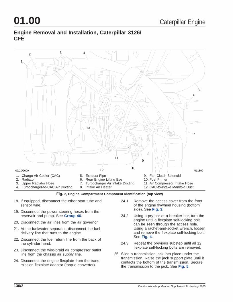
09/20/2000
1
2 3 4
5
6
7
8
9
10
11
12
13
f011899
1. Charge Air Cooler (CAC)2. Radiator3. Upper Radiator Hose4. Turbocharger-to-CAC Air Ducting
5. Exhaust Pipe6. Rear Engine Lifting Eye7. Turbocharger Air Intake Ducting8. Intake Air Heater
9. Fan Clutch Solenoid10. Fuel Primer11. Air Compressor Intake Hose12. CAC-to-Intake Manifold Duct
Fig. 2, Engine Compartment Component Identification (top view)
Caterpillar Engine01.00Engine Removal and Installation, Caterpillar 3126/CFE
Condor Workshop Manual, Supplement 0, January 2000130/2

26. Remove the 12 transmission flange bolts fromthe engine flywheel housing. See Fig. 6 .
WARNINGThe crane and lifting chains used to remove theengine must be capable of safely lifting and sup-porting two metric tons. Once the engine mountsare disconnected, do not work under the engineuntil it is securely supported on engine stands.An unsecured engine may fall, causing personalinjury or death, and component damage.
27. Remove the engine from the vehicle.
27.1 Attach the chain to the existing liftingeyes at the front and the rear of the en-gine. See Fig. 2 and Fig. 7 .
27.2 With the engine lifting eyes connected bychain to the crane, raise the craneenough to tighten the chains, but notenough to lift the front of the vehicle.
27.3 Remove the nuts from the bolts from thefront engine mount.
09/21/2000 f011901
1 2
3
1. Transmission2. Transmission Flexplate Adaptor (torque converter)3. Engine Flexplate
Fig. 3, Flexplate Access Cover
09/20/2000 f011900
1
2
1. Cab Heater Hose2. Access Plug
Fig. 4, Flexplate Adaptor-to-Flexplate Mounting BoltAccess Plug
08/04/94 f260112a
Fig. 5, Secure the Transmission
f260117a08/04/94
Fig. 6, Remove the Flange Bolts
Caterpillar Engine 01.00Engine Removal and Installation, Caterpillar 3126/
CFE
Condor Workshop Manual, Supplement 0, January 2000 130/3

27.4 With the engine securely supported bythe crane and lifting chains, separate therear engine mounts by removing the nutfrom the bolt that runs down throughmount.
27.5 Slightly raise the engine, then separatethe engine from the transmission.
NOTE: Be sure that the engine has clearedthe torque converter before continuing toremove the engine from the vehicle.
27.6 Using the crane, lift the engine and pull itforward.
27.7 Once the engine is clear of the vehicle,place the engine on an engine stand.
Installation1. Check all of the front and rear engine support
parts for damage or extreme wear. Replace theparts as needed.
Install the isolators in the engine front crossmem-ber. Coat the rubber mounts with soapy water,and install them in the rear engine mounts.
CAUTIONDo not lubricate the components with oil, grease,or silicone lubricants, which can soften the rub-ber and damage the mounts.
WARNINGThe crane and lifting chains used to install theengine must be capable of safely lifting and sup-porting two metric tons. Once the engine is re-moved from the engine stands, do not work un-der the engine until it is securely supported onthe engine mounts. An unsecured engine mayfall, causing personal injury or death, and com-ponent damage.
NOTE: Make sure that all wires are clear beforelowering the engine into the vehicle.
2. Install the engine in the vehicle.
2.1 Attach the chain to the existing liftingeyes at the front and the rear of the en-gine.
2.2 With the two engine lifting eyes con-nected by chain to the crane, lift the en-gine, and position it in the engine com-partment.
CAUTIONThe engine flywheel housing must be free to seatagainst the transmission. If the engine flywheelhousing will not seat freely (without force)against the transmission, then move the engineaway from the transmission and correct the prob-lem. Do not force the engine flywheel housing toseat against the transmission housing by install-ing and tightening the flange bolts. To do socould cause damage to the transmission.
2.3 With the bolt holes in the transmissionflange aligned with the mounting holes inthe engine flywheel housing, seat thetransmission squarely against the fly-wheel housing. To help push the bellhousing square against the flywheelhousing, insert a pry bar between the rearengine support bracket and the framebracket, and push forward. If the trans-mission will not seat freely (without ex-cessive force) against the engine flywheelhousing, then move the transmissionaway from the engine and correct theproblem.
2.4 Install the transmission flange boltsfinger-tight.
09/19/2000 f011898
Fig. 7, Front Engine Lifting Eye
Caterpillar Engine01.00Engine Removal and Installation, Caterpillar 3126/CFE
Condor Workshop Manual, Supplement 0, January 2000130/4

2.5 Connect the engine to the rear enginemounts, and tighten each bolt that runsdown through the engine leg, rubber iso-lators, and engine mount 241 lbf·ft (327N·m).
2.6 Remove the nuts from the bolts from thefront engine mount. Tighten the nuts 136lbf·ft (184 N·m).
2.7 Once the engine is securely installed inthe vehicle, remove the lifting chains.
3. Remove the transmission jack from the transmis-sion.
NOTE: Do not tighten any flexplate-to-flexplateadaptor bolts until all of the bolts have been in-stalled and tightened finger-tight.
4. Attach the engine flexplate to the transmissionflexplate adaptor (torque converter).
4.1 Using a pry bar or a breaker bar, turn theengine until the next flexplate bolt holecan be seen through the access hole.Install a M8 x 1.25 flexplate self-lockingbolt into the flexplate bolt hole and tightenit finger-tight.
4.2 Repeat the previous substep until all 12flexplate self-locking bolts are installedfinger-tight.
4.3 After all the self-locking bolts have beeninstalled finger-tight, tighten them 13 to18 lbf·ft (18 to 24 N·m).
4.4 Install the access cover (plug) on thefront of the engine flywheel housing. SeeFig. 3 .
5. Connect the wire-braid air compressor outlet lineto the chassis air supply line.
6. Connect the fuel delivery and return lines.
7. Connect the air lines to the air governor on topof the air compressor.
8. Connect the power steering components. Forinstructions, see Group 46 .
9. If equipped, connect the ether start tube andsensor wire.
10. Connect the engine wiring.
10.1 Connect the wiring to the starter.
10.2 Connect the wiring to the alternator.
10.3 Connect the wiring to the coolant tem-perature sensors.
10.4 Plug the lower wiring harness connectorinto the electronic control module.
10.5 Connect any remaining electrical harnessconnectors.
11. If removed, install the fan and fan clutch. SeeSection 20.02 .
12. Replace the refrigerant compressor O-rings, thenconnect the hoses to the compressor.
13. Connect the cab heater hoses.
14. Install the radiator, CAC and A/C condenser. SeeSection 20.01 .
15. Remove the intake manifold and turbochargercovers, then install the ducting.
16. Install the vertical air intake snorkel upperbracket assembly and related components. SeeSection 09.00 , Subject 130.
17. Fill the cooling system with coolant.
18. Fill the engine with the proper type and quantityof engine oil.
19. Fill and bleed the power steering system. Forinstructions, see Group 46 .
20. Prime the fuel system to ease starting.
21. Install the exhaust ducting that runs between theturbocharger and the muffler. See Group 49 .
22. Connect the batteries.
23. Start the engine, and check for leaks. Repair anyleaks found.
DANGERBefore tilting the cab or returning the cab to thenormal operating position, read the instructionsand the hazard notices in Section 60.00 . Failureto follow these instructions could cause the cabto fall and hit or crush a person, which will resultin severe injury or death.
24. Return the cab to the normal operating position.
25. Test drive the vehicle.
Caterpillar Engine 01.00Engine Removal and Installation, Caterpillar 3126/
CFE
Condor Workshop Manual, Supplement 0, January 2000 130/5

Drive Belt Replacement1. Park the vehicle, apply the parking brakes, and
chock the tires.
DANGERBefore tilting the cab or returning the cab to op-erating position, read the instructions and hazardnotices in Section 60.00 . Failure to follow theseinstructions could cause the cab to fall and hit orcrush a person, which will result in severe injuryor death.
2. Tilt the cab.
3. Insert a 1/2-inch drive ratchet into the squarehole in the drive belt tensioner pulley, and turnthe tensioner down and off the belt. See Fig. 1 ,Ref. 4.
4. Remove the drive belt, without prying or rolling itoff of the pulleys.
5. Inspect the pulleys and the drive belt (even ifinstalling a new belt) as instructed in Sub-ject 100 .
CAUTIONWhen installing a serpentine drive belt, route thebelt correctly. If the belt is not routed correctly,the water pump pulley may rotate in the wrongdirection, allowing the engine to overheat.
6. Position the replacement drive belt over all thepulleys except the drive belt tensioner pulley. Forthe correct drive belt routing, see Fig. 2 for ve-hicles with a refrigerant compressor, and Fig. 3for vehicles without a refrigerant compressor.
7. Insert a 1/2-inch drive ratchet into the squarehole in the belt tensioner, and turn the tensionerclockwise. See Fig. 1 .
8. Position the tensioner against the belt, and re-move the drive ratchet from the tensioner.
9. Check that the drive belt has been correctlyrouted; see Fig. 2 for vehicles with a refrigerant
03/28/2005 f012073
1
2
3
4
1. Alternator Pulley2. Tensioner Pulley3. Drive Belt
4. Drive RatchetLocation
Fig. 1, Relieving/Adjusting Belt Tension
04/04/2005 f012080
1
2
2
3
4
5
6
NOTE: Turn the belt tensioner counterclockwise, off thebelt.
1. Tensioner Pulley2. Idler Pulley3. Alternator
4. AC Compressor5. Fan Clutch6. Drive Belt
Fig. 2, Drive Belt Routing With a RefrigerantCompressor (C-11 shown, C-13 similar)
Caterpillar Engine 01.00Drive Belt Replacement, C-7/C-9
Condor Workshop Manual, Supplement 7, September 2005 140/1

compressor, and Fig. 3 for vehicles without arefrigerant compressor.
10. Start the engine and check the drive belt forproper operation.
11. Shut down the engine. If there is a problem, cor-rect it, and check the drive belt again.
DANGERBefore tilting the cab or returning the cab to op-erating position, read the instructions and hazardnotices in Section 60.00 . Failure to follow theseinstructions could cause the cab to fall and hit orcrush a person, which will result in severe injuryor death.
12. Lower the cab.
13. Remove the chocks from the tires.
04/04/2005 f012079
1
23
4
5
2
NOTE: Turn the belt tensioner counterclockwise, off thebelt.
1. Tensioner Pulley2. Idler Pulley3. Alternator
4. Fan Clutch5. Drive Belt
Fig. 3, Drive Belt Routing Without a RefrigerantCompressor (C-11 shown, C-13 similar)
Caterpillar Engine01.00Drive Belt Replacement, C-7/C-9
Condor Workshop Manual, Supplement 7, September 2005140/2

Drive Belt Replacement1. Park the vehicle, apply the parking brakes, and
chock the tires.
DANGERBefore tilting the cab or returning the cab to op-erating position, read the instructions and hazardnotices in Section 60.00 . Failure to follow theseinstructions could cause the cab to fall and hit orcrush a person, which will result in severe injuryor death.
2. Tilt the cab.
3. Insert a 1/2-inch drive ratchet into the squarehole in the drive belt tensioner pulley, and turnthe tensioner down and off the belt. See Fig. 1 ,Ref. 4.
4. Remove the drive belt, without prying or rolling itoff of the pulleys.
5. Inspect the pulleys and the drive belt (even ifinstalling a new belt) as instructed in Sub-ject 100 .
CAUTIONWhen installing a serpentine drive belt, route thebelt correctly. If the belt is not routed correctly,the water pump pulley may rotate in the wrongdirection, allowing the engine to overheat.
6. Position the replacement drive belt over all thepulleys except the drive belt tensioner pulley. Forthe correct drive belt routing, see Fig. 2 for ve-hicles with a refrigerant compressor, and Fig. 3for vehicles without a refrigerant compressor.
7. Insert a 1/2-inch drive ratchet into the squarehole in the belt tensioner, and turn the tensionerclockwise. See Fig. 1 .
8. Position the tensioner against the belt, and re-move the drive ratchet from the tensioner.
9. Check that the drive belt has been correctlyrouted; see Fig. 2 for vehicles with a refrigerant
03/28/2005 f012073
1
2
3
4
1. Alternator Pulley2. Tensioner Pulley3. Drive Belt
4. Ratchet DriveLocation
Fig. 1, Relieving/Adjusting Belt Tension
04/04/2005 f012080
1
2
2
3
4
5
6
NOTE: Turn the belt tensioner counterclockwise, off thebelt.
1. Tensioner Pulley2. Idler Pulley3. Alternator
4. AC Compressor5. Fan Clutch6. Drive Belt
Fig. 2, Drive Belt Routing With a RefrigerantCompressor (C-11 shown, C-13 similar)
Caterpillar Engine 01.00Drive Belt Replacement, C-11/C-13
Condor Workshop Manual, Supplement 7, September 2005 150/1

compressor, and Fig. 3 for vehicles without arefrigerant compressor.
10. Start the engine and check the drive belt forproper operation.
11. Shut down the engine. If there is a problem, cor-rect it, and check the drive belt again.
DANGERBefore tilting the cab or returning the cab to op-erating position, read the instructions and hazardnotices in Section 60.00 . Failure to follow theseinstructions could cause the cab to fall and hit orcrush a person, which will result in severe injuryor death.
12. Lower the cab.
13. Remove the chocks from the tires.
04/04/2005 f012079
1
23
4
5
2
NOTE: Turn the belt tensioner counterclockwise, off thebelt.
1. Tensioner Pulley2. Idler Pulley3. Alternator
4. Fan Clutch5. Drive Belt
Fig. 3, Drive Belt Routing Without a RefrigerantCompressor (C-11 shown, C-13 similar)
Caterpillar Engine01.00Drive Belt Replacement, C-11/C-13
Condor Workshop Manual, Supplement 7, September 2005150/2

Engine Mount Fastener Torque
Fastener Description Bolt Size Grade Torque: lbf·ft (N·m)
Frame Rail Leg-to-Frame Rail 5/8–11 x 2.25 Inch 8 190 (258)
Frame Rail Leg-to-Engine Mount
(HD transmission installation)1–8 5 280–380 (380–515)
Frame Rail Leg-to-Engine Mount
(MD transmission installation)5/8–11 x 3.5 Inch 8 120–152 (163–206)
Engine Mount-to-Flywheel Housing
(MD transmission installation)3/4–10 x 2 Inch 8
Aluminum flywheel housings:
180–220 (244–298)
Iron flywheel housings:
213–269 (289–365)
Engine Mount-to-Transmission
(HD transmission installation)M16 x 50 Class
10.9 168–196 (228–266)
Front Engine Support Bracket-to-Front
Engine Mount5/8–11 x 5 Inch 8 140–160 (190–217)
Rear Engine-to-Mount — — 213–269 (289–365)
Front Engine-to-Mount — — 213–269 (289–365)
Table 1, Engine Mount Fastener Torque
Engine Leg-to-Flywheel Housing Fastener Torque
Engine Fastener Size Torque: lbf·ft(N·m)
Plus/Minuslbf·ft (N·m)
C-7 M14– 2 94–100 (128–136) 6 (8)
C-9, C-10, C-12 C-13, C-15, C-16 3/4–10 170–190 (231–258) 20 (27)
Table 2, Engine Leg-to-Flywheel Housing Fastener Torque
Drive Belt Tension
Engine Component Belt Tension, New Beltlb (kg)
Belt Tension, Used Beltlb (kg)
CFE Refrigerant Compressor 80–100 (36–45) 80–100 (36–45)
3176 Refrigerant Compressor 80–100 (36–45) 80–100 (36–45)
3406Alternator and Refrigerant Compressor 115–125 (52–57) 80–100 (36–45)
Fan 115–125 (52–57) 80–100 (36–45)
Table 3, Drive Belt Tension
Caterpillar Engine 01.00Specifications
Condor Workshop Manual, Supplement 7, September 2005 400/1

General InformationThree mounts support the engine and transmission,holding a total of almost 1,800 lb (816 kg). Two ofthe engine mounts support the rear of the engineand transmission assembly. The third supports thefront of the assembly.
The rear mounts are positioned on the engine fly-wheel housing.
The front engine mount is an underslung crossmem-ber under the front of the engine. It supports abracket that is bolted to the engine at each side ofthe vibration damper pulley.
To isolate the engine and transmission from roadshock, and to isolate the vehicle frame from enginevibration, the engine mounts are sandwiched be-tween rubber isolator cushions (sometimes calledrestriction pads). Steel spacers protect the cushionsfrom wearing on the engine support brackets, andbolts run through the mount, cushions, and spacersto hold the assembly together and hold the engineon the mount.
Engine Mounts 01.02General Information
Condor Workshop Manual, Supplement 0, January 2000 050/1

Replacement (See Fig. 1)
1. Park the vehicle on a level surface, shut downthe engine, apply the parking brakes, and chockthe rear tires.
DANGERBefore tilting the cab or returning the cab to thenormal operating position, read the instructionsand the hazard notices in Section 60.00 . Failureto follow these instructions could cause the cabto fall and hit or crush a person, which will resultin severe injury or death.
2. Tilt the cab.
WARNINGThe jack used to lift the transmission must becapable of safely lifting and supporting 4400 lbs(1996 kg). Once the mount is disconnected, donot get under the transmission until it is securelysupported on stands. An unsecured transmissionmay fall, causing personal injury or death, andcomponent damage.
3. Disconnect the left rear engine mount.
3.1 Place a jack under the transmission, andraise the jack until it’s braced against thetransmission.
3.2 Remove the bolt from the left rear mount.Save the fasteners and the rubber isola-tor cushions, and spacer(s).
3.3 Lift the transmission slightly to take itsweight off the left rear mount. Placestands under the transmission to keep itoff the mount.
4. Remove the bolts which secure the mount to theframe rail. Remove the mount from the framerail.
5. Place a new mount against the inside of theframe rail, and secure it with capscrews, wash-ers, and nuts. Tighten the nuts 190 lbf·ft (258N·m).
6. If removed, install the engine support bracket onthe left side of the engine. Apply Loctite® 271 tothe capscrews, and tighten as follows:
For aluminum flywheel housings: tighten the nuts180 to 220 lbf·ft (244 to 298 N·m).
For iron flywheel housings: tighten the nuts 213to 269 lbf·ft (289 to 365 N·m).
NOTE: Inspect the rubber isolators for wear ordamage, and replace them if necessary.
7. Install the rubber isolators in the engine mount.
CAUTIONDo not lubricate the components with oil, grease,or silicone lubricants; they will deteriorate therubber isolators.
WARNINGThe jack used to lower the transmission must becapable of safely lifting and supporting 4400 lbs(1996 kg). Once the transmission is removedfrom the stands, do not get under the transmis-sion until it is securely installed on the mount.An unsecured transmission may fall, causing per-sonal injury or death, and component damage.
8. Secure the engine to the mounts.
08/21/2000 f220080
1
3
2
4 5 6
7
8
1. Frame2. Capscrew, 1/2–13 x 1.5 Inch, Grade 83. Upper Isolator4. Capscrew, 3/4–10 x 5.00 Inch, Grade 85. Washer6. Engine Support Bracket7. Lower Isolator8. Capscrew, M14 x 35, Grade 10.9
Fig. 1, Rear Engine Mount Assembly
Engine Mounts 01.02Rear Engine Mount Replacement
Condor Workshop Manual, Supplement 0, January 2000 100/1

8.1 If not in place, set a jack under the trans-mission and raise the jack until it isbraced against the transmission.
8.2 Lift the transmission slightly to removethe stands. Remove the stands, and care-fully lower the transmission onto the en-gine mount.
8.3 Holding the lower isolator and spacer inplace, install the bolt in the left rearmount, and secure it with the nut andhardened washer. Tighten the nut 120 to152 lbf·ft (163 to 206 N·m).
9. Repeat this procedure for the other rear mount.
10. Remove the jack from under the transmission.
DANGERBefore tilting the cab or returning the cab to thenormal operating position, read the instructionsand the hazard notices in Section 60.00 . Failureto follow these instructions could cause the cabto fall and hit or crush a person, which will resultin severe injury or death.
11. Return the cab to the normal operating position.
12. Remove the chocks from the tires.
Engine Mounts01.02Rear Engine Mount Replacement
Condor Workshop Manual, Supplement 0, January 2000100/2

Replacement (See Fig. 1)
1. Park the vehicle on a level surface, shut downthe engine, apply the parking brakes, and chockthe rear tires.
DANGERBefore tilting the cab or returning the cab to thenormal operating position, read the instructionsand the hazard notices in Section 60.00 . Failureto follow these instructions could cause the cabto fall and hit or crush a person, which will resultin severe injury or death.
2. Tilt the cab.
WARNINGThe lifting device and chain used to lift the en-gine must be capable of safely lifting and sup-porting two metric tons. Once the engine mountis disconnected, do not get under the engine un-til it is securely supported on engine stands. Anunsecured engine may fall, causing personal in-jury or death, and component damage.
3. Disconnect the engine from the front enginemount.
3.1 Attach a chain to the front engine liftinghook(s), and position a lifting device to liftthe engine. Attach the chain to the liftingdevice, and raise the chain to remove anyslack.
3.2 Remove the bolt(s) from the front enginemount. Save the fasteners, rubber isolatorcushions, and spacer(s).
NOTE: In order to raise the front of the en-gine, you may have to loosen the bolts thatrun through the rear engine mounts.
3.3 Lift the engine slightly to take its weightoff the front engine mount. Place enginestands under the engine to keep it off theengine mount.
4. If you’re replacing the front engine supportbracket, refer to the engine manufacturer’s ser-vice literature.
5. Inspect the engine mount rubber isolators forwear or damage and replace them if necessary.
CAUTIONDo not lubricate the components with oil, grease,or silicone lubricants; they will deteriorate therubber isolators.
6. Install the upper isolator(s) in the engine mount.
WARNINGThe lifting device and chain used to lower theengine must be capable of safely lifting and sup-porting two metric tons. Once the engine is re-moved from the engine stands, do not get under
f22004506/01/93
1
2
3
5
4
6
7
8
9
1. Front Engine Bracket2. Nut3. Washer4. Spacer5. Upper Isolator6. Front Engine Mount7. Lower Isolator8. Washer9. Capscrew
Fig. 1, Front Engine Mount
Engine Mounts 01.02Front Engine Mount Replacement
Condor Workshop Manual, Supplement 0, January 2000 110/1

the engine until it is securely installed on the en-gine mount. An unsecured engine may fall, caus-ing personal injury or death, and componentdamage.
7. Secure the engine to the front engine mount.
7.1 Attach a chain to the front engine liftinghook(s). Attach the chain to a lifting de-vice, and raise the chain to remove anyslack.
7.2 Lift the engine slightly to remove the en-gine stands. Remove the stands, andcarefully lower the engine onto the enginemount.
7.3 Holding the lower isolator in place, installthe bolts in the front engine mount andsecure them with the nuts and washers.Tighten the nuts 140 to 160 lbf·ft (190 to217 N·m).
NOTE: If you loosened the bolts that runthrough the rear engine mounts, tightenthose bolts 280 to 380 lbf·ft (380 to 515N·m).
7.4 Remove the lifting chain from the enginelifting hooks.
DANGERBefore tilting the cab or returning the cab to thenormal operating position, read the instructionsand the hazard notices in Section 60.00 . Failureto follow these instructions could cause the cabto fall and hit or crush a person, which will resultin severe injury or death.
8. Return the cab to the normal operating position.
9. Remove the chocks from the tires.
Engine Mounts01.02Front Engine Mount Replacement
Condor Workshop Manual, Supplement 0, January 2000110/2

Replacement (See Fig. 1)
1. Park the vehicle on a level surface, shut downthe engine, apply the parking brakes, and chockthe rear tires.
DANGERBefore tilting the cab or returning the cab to thenormal operating position, read the instructionsand the hazard notices in Section 60.00 . Failureto follow these instructions could cause the cabto fall and hit or crush a person, which will resultin severe injury or death.
2. Tilt the cab.
WARNINGThe jack used to lift the transmission must becapable of safely lifting and supporting 4400 lbs(1996 kg). Once the mount is disconnected, donot get under the transmission until it is securelysupported on stands. An unsecured transmissionmay fall, causing personal injury or death, andcomponent damage.
3. Disconnect the left rear engine mount.
3.1 Place a jack under the transmission, andraise the jack until it’s braced against thetransmission.
3.2 Remove the bolt from the left rear mount.Save the fasteners and the rubber isola-tor cushions, and spacer(s).
3.3 Lift the transmission slightly to take itsweight off the left rear mount. Placestands under the transmission to keep itoff the mount.
3.4 Remove the mount from the frame rail.For instructions, see Subject 100 . Re-move and discard the isolator.
CAUTIONDo not lubricate the new components with oil,
grease, or silicone lubricants; they will deterio-rate the rubber isolators.
4. Install the new isolator in the mount, and installthe mount on the frame rail. For instructions, seeSubject 100 .
WARNINGThe jack used to lower the transmission must becapable of safely lifting and supporting 4400 lbs(1996 kg). Once the transmission is removedfrom the stands, do not get under the transmis-sion until it is securely installed on the mount.An unsecured transmission may fall, causing per-sonal injury or death, and component damage.
5. Secure the transmission to the mount.
5.1 If not in place, set a jack under the trans-mission and raise the jack until it isbraced against the transmission.
5.2 Lift the transmission slightly to removethe stands. Remove the stands, and care-fully lower the transmission onto themount.
5.3 Holding the lower isolator and spacer inplace, install the bolt in the left rearmount, and secure it with the nut andhardened washer. Tighten the nut 120 to152 lbf·ft (163 to 206 N·m).
6. Repeat this procedure for the other rear mount.
08/21/2000 f220080
1
3
2
4 5 6
7
8
1. Frame2. Capscrew, 1/2–13 x 1.5 Inch, Grade 83. Upper Isolator4. Capscrew, 3/4–10 x 5.00 Inch, Grade 85. Washer6. Engine Support Bracket7. Lower Isolator8. Capscrew, M14 x 35, Grade 10.9
Fig. 1, Rear Engine Mount Assembly
Engine Mounts 01.02Rear Engine Mount Isolator Replacement
Condor Workshop Manual, Supplement 0, January 2000 120/1

7. Remove the jack from under the transmission.
DANGERBefore tilting the cab or returning the cab to thenormal operating position, read the instructionsand the hazard notices in Section 60.00 . Failureto follow these instructions could cause the cabto fall and hit or crush a person, which will resultin severe injury or death.
8. Return the cab to the normal operating position.
9. Remove the chocks from the tires.
Engine Mounts01.02Rear Engine Mount Isolator Replacement
Condor Workshop Manual, Supplement 0, January 2000120/2

Replacement (See Fig. 1)
1. Park the vehicle on a level surface, shut downthe engine, apply the parking brakes, and chockthe rear tires.
DANGERBefore tilting the cab or returning the cab to thenormal operating position, read the instructionsand the hazard notices in Section 60.00 . Failureto follow these instructions could cause the cabto fall and hit or crush a person, which will resultin severe injury or death.
2. Tilt the cab.
WARNINGThe lifting device and chain used to lift the en-gine must be capable of safely lifting and sup-porting two metric tons. Once the engine mountis disconnected, do not get under the engine un-til it is securely supported on engine stands. Anunsecured engine may fall, causing personal in-jury or death, and component damage.
3. Disconnect the engine from the front enginemount.
3.1 Attach a chain to the front engine liftinghook(s), and position a lifting device to liftthe engine. Attach the chain to the liftingdevice, and raise the chain to remove anyslack.
3.2 Remove the bolt(s) from the front enginemount. Save the fasteners, and the spac-er(s). Discard the rubber isolator cush-ions.
NOTE: In order to raise the front of the en-gine, you may have to loosen the bolts thatrun through the rear engine mounts.
3.3 Lift the engine slightly to take its weightoff the front engine mount. Place enginestands under the engine to keep it off theengine mount.
CAUTIONDo not lubricate the new components with oil,grease, or silicone lubricants; they will deterio-rate the rubber isolators.
4. Install the upper isolator(s) in the engine mount.
WARNINGThe lifting device and chain used to lower theengine must be capable of safely lifting and sup-porting two metric tons. Once the engine is re-moved from the engine stands, do not get underthe engine until it is securely installed on the en-gine mount. An unsecured engine may fall, caus-ing personal injury or death, and componentdamage.
f22004506/01/93
1
2
3
5
4
6
7
8
9
1. Front Engine Bracket2. Nut3. Washer4. Spacer5. Upper Isolator6. Front Engine Mount7. Lower Isolator8. Washer9. Capscrew
Fig. 1, Front Engine Mount
Engine Mounts 01.02Front Engine Mount Isolator Replacement
Condor Workshop Manual, Supplement 0, January 2000 130/1

5. Secure the engine to the front engine mount.
5.1 Attach a chain to the front engine liftinghook(s). Attach the chain to a lifting de-vice, and raise the chain to remove anyslack.
5.2 Lift the engine slightly to remove the en-gine stands. Remove the stands, andcarefully lower the engine onto the enginemount.
5.3 Holding the lower isolator in place, installthe bolts in the front engine mount andsecure them with the nuts and washers.Tighten the nuts 140 to 160 lbf·ft (190 to217 N·m).
NOTE: If you loosened the bolts that runthrough the rear engine mounts, tightenthose bolts 280 to 380 lbf·ft (380 to 515N·m).
5.4 Remove the lifting chain from the enginelifting hook(s).
DANGERBefore tilting the cab or returning the cab to thenormal operating position, read the instructionsand the hazard notices in Section 60.00 . Failureto follow these instructions could cause the cabto fall and hit or crush a person, which will resultin severe injury or death.
6. Return the cab to the normal operating position.
7. Remove the chocks from the tires.
Engine Mounts01.02Front Engine Mount Isolator Replacement
Condor Workshop Manual, Supplement 0, January 2000130/2

Engine Mount Bolt Torques
Description Bolt Size Grade Torque: lbf·ft (N·m)
Frame Rail Leg-to-Frame Rail Capscrew 5/8–11 x 2.25 Inch Grade 8 190 (258)
Frame Rail Leg-to-Engine Mount Bolt 1–8 Inch Grade 5 280–380 (380–515)
Frame Rail Leg-to-Engine Mount Bolt 5/8–11 x 3.5 Inch Grade 8 120–152 (163–206)
Engine Mount-to-Flywheel Housing Capscrew 3/4–10 x 2 Inch Grade 8 Aluminum flywheel housings: 180–220 (244–298)
Iron flywheel housings: 213–269(289–365)
Front Engine Support Bracket-to-Front EngineMount Bolt
5/8–11 x 5 Inch Grade 8 140–160 (190–217)
Table 1, Engine Mount Torques
Engine Mounts 01.02Specifications
Condor Workshop Manual, Supplement 0, January 2000 400/1

General InformationAn engine block heater keeps the engine coolantabout 80°F (27°C) warmer than the ambient air tem-perature. In cold weather, the heater helps enginestarting and reduces wear on the piston walls.
When starting the engine, the diesel normally igniteson the compression stroke of each piston, when thecompressed air within the cylinder reaches about725°F (385°C). However, during cold weather starts,the heat of the compressed air dissipates into thesurrounding engine block so the diesel may neverreach the temperature it needs to ignite. Using theengine block heater, the engine block is alreadywarm so heat is held in the cylinder to ignite the die-sel. To reduce engine wear, the block heater warmsthe oil film on the piston walls and reduces pistondrag caused by cold oil film.
The heater consists of an element that bolts into theside of the engine water jacket. A heater power cordplugs into the outside end of the element.
To turn on the heater, connect the heater cord to apower source. The element has no thermostat. Heatdissipating from the engine block prevents coolantoverheating.
Engine Block Heater 01.03General Information
Condor Workshop Manual, Supplement 0, January 2000 050/1

Replacement1. Park the vehicle on a level surface, shut down
the engine, apply the parking brakes, and chockthe rear tires.
DANGERBefore tilting the cab or returning the cab to thenormal operating position, read the instructionsand the hazard notices in Section 60.00 . Failureto follow these instructions could cause the cabto fall and hit or crush a person, which will resultin severe injury or death.
2. Tilt the cab.
WARNINGBefore starting the procedures below, read theinformation in Safety Precautions, 100. Failure tofollow the safety precautions during service op-erations on the air brake system can cause per-sonal injury.
3. Drain the radiator. For instructions, refer to Sec-tion 20.01 , Subject 100.
4. If applicable, unscrew the threaded cover thatsecures the cord to the element.
5. Pull the cord off the element.
6. Using a 1-1/8 inch socket, loosen and removethe jam nut (if applicable) and unscrew the ele-ment from the engine block.
7. Position the heater element in the engine block.
Coat the threads of the element with a smallamount of sealant. For the approved sealants,refer to Specifications, 400 .
8. Screw the element into the engine block handtight, then use a wrench to turn the element1-1/2 turns more.
9. Plug the cord into the element and (if applicable)secure it by screwing the threaded cord cover inplace.
10. Fill the cooling system. For instructions, refer toSection 20.01 , Subject 100.
DANGERBefore tilting the cab or returning the cab to thenormal operating position, read the instructionsand the hazard notices in Section 60.00 . Failureto follow these instructions could cause the cabto fall and hit or crush a person, which will resultin severe injury or death.
11. Return the cab to the normal operating position.
12. Start the engine and check for leaks. Repair anyleaks as necessary. Run the engine for half anhour to purge any air from the coolant system.
13. To test the heater, plug a wattmeter into a powersource, and connect the heater cord to themeter. A reading on the meter will indicate theheater is working.
14. Remove the chocks from the tires.
Engine Block Heater 01.03Block Heater Element Replacement
Condor Workshop Manual, Supplement 0, January 2000 100/1

TroubleshootingUse the following procedures to check for the mostcommon engine block heater problems.
Wiring Problems1. Park the vehicle on a level surface, shut down
the engine, apply the parking brakes, and chockthe rear tires.
DANGERBefore tilting the cab or returning the cab to thenormal operating position, read the instructionsand the hazard notices in Section 60.00 . Failureto follow these instructions could cause the cabto fall and hit or crush a person, which will resultin severe injury or death.
2. Tilt the cab.
3. Unscrew the threaded cover that secures thecord to the element. Pull the cord off the ele-ment.
4. Using an ohmmeter, check the continuity be-tween the two poles of the element. The resis-tance should be very low, typically between 9and 10 ohms. If there is no reading, the elementhas burned out, and if the reading is very high,the element is about to burn out.
5. If the element is good, check the cord. Plug thecord into the element and secure it by screwingthe threaded cover in place.
6. Using an ohmmeter at the receptacle, check thecontinuity between the two power terminals. Theresistance should be low, typically between 9and 10 ohms. If there is no reading or a veryhigh reading, the cord is damaged. Replace thecord.
7. Check the continuity between each power termi-nal and the ground terminal. There should be noohmmeter reading. If there is a reading, replacethe cord.
8. Check the ohmmeter reading between theground terminal and a good vehicle ground. Thereading should be zero. If not, replace the cord.
DANGERBefore tilting the cab or returning the cab to thenormal operating position, read the instructionsand the hazard notices in Section 60.00 . Failureto follow these instructions could cause the cabto fall and hit or crush a person, which will resultin severe injury or death.
9. Return the cab to the normal operating position.
10. Remove the chocks from the tires.
Fouled Element1. Park the vehicle on a level surface, shut down
the engine, apply the parking brakes, and chockthe rear tires.
DANGERBefore tilting the cab or returning the cab to thenormal operating position, read the instructionsand the hazard notices in Section 60.00 . Failureto follow these instructions could cause the cabto fall and hit or crush a person, which will resultin severe injury or death.
2. Tilt the cab.
WARNINGBefore starting the procedures below, read theinformation in Safety Precautions, 100. Failure tofollow the safety precautions during service op-erations on the air brake system can cause per-sonal injury.
3. Drain the radiator. For instructions, refer to Sec-tion 20.01 .
4. Unscrew the threaded cover that secures thecord to the element. Pull the cord off the ele-ment.
5. Remove the element from the engine block. Forinstructions, refer to the Subject 100 .
6. Inspect the element for residue deposits, discol-oration, or damage.
Greenish residue indicates the coolant solutioncontains too much antifreeze. Replace the ele-ment, and refer to Group 20 for the recom-mended antifreeze/water ratio.
Engine Block Heater 01.03Troubleshooting
Condor Workshop Manual, Supplement 0, January 2000 300/1

Gray or black residue indicates anti-leak coolantadditives have been added to the system. Re-place the element, and refer to Group 20 of theCondor Maintenance Manual for the recom-mended coolant additives.
Blue or black discoloration on the element indi-cates the coolant system needs more coolant.Replace the element, and fill the coolant systemuntil coolant is visible in the surge tank sightglass.
Holes in the element indicate the coolant solutioncontains too little antifreeze. The weak solution isboiling inside the engine block and causing pit-ting of the element and block. Replace the ele-ment, and refer to Group 20 of this manual forthe recommended antifreeze to water concentra-tions.
For element installation instructions, refer toSubject 100 .
DANGERBefore tilting the cab or returning the cab to thenormal operating position, read the instructionsand the hazard notices in Section 60.00 . Failureto follow these instructions could cause the cabto fall and hit or crush a person, which will resultin severe injury or death.
7. Return the cab to the normal operating position.
8. Remove the chocks from the tires.
Engine Block Heater01.03Troubleshooting
Condor Workshop Manual, Supplement 0, January 2000300/2

Specifications
Approved Sealants• Loctite 567
• Henkel 790 Pipegrip
• Perma-Loc LH-150
Engine Block Heater 01.03Specifications
Condor Workshop Manual, Supplement 0, January 2000 400/1

General DescriptionDuring cold weather starts, the KBi starting fluid sys-tem injects vaporized ether into the engine manifoldto help ignite the diesel fuel in the cylinders. The die-sel normally ignites on the compression stroke ofeach piston, when the compressed air within the cyl-inder reaches about 725°F (385°C). However, duringcold weather starts, the heat of the compressed airdissipates into the surrounding engine block so thediesel may never reach the temperature it needs toignite. Ether ignites at 360°F (182°C). Therefore,ether vapor injected with the engine intake air ignitesat the lower cylinder temperature, and the burningether ignites the diesel.
Using the starting fluid system reduces the neces-sary cranking time in cold weather, and it preventsexcessive wear on the battery and starter.
When the engine is cold, the KBi system begins in-jecting ether when the starter is cranked. The systemcontinues injecting ether vapor into the manifold for ashort time to prevent stalling. The system consists ofthe starting fluid cylinder, the ether injection nozzle inthe engine manifold, and the engine temperaturesensor.
The starting fluid cylinder ( Fig. 1 ) is mounted underthe front steps. It fits into the Dieselmatic® valve andBlockor® fitting which measure, hold, and release acontrolled amount of fluid for each start attempt.
Ether travels through plastic tubing to the enginemanifold where it sprays through the injection nozzleinto the engine intake air. Inside the manifold, vapor-ized ether fills the cylinders and ignites.
If the weather is warm, or the engine is alreadywarmed, the engine temperature sensor mounted inthe engine water jacket prevents the KBi from inject-ing ether vapor. The system will inject ether only ifthe engine is cooler than about 40°F (4°C).
f010385a06/17/94
1
2
3
1. Starting Fluid Cylinder2. Dieselmatic Valve3. Blockor Fitting
Fig. 1, KBi Ether Start System
Ether Start System 01.04General Information
Condor Workshop Manual, Supplement 0, January 2000 050/1

Replacement (See Fig. 1)
1. Park the vehicle on a level surface, shut downthe engine, apply the parking brakes, and chockthe rear tires.
WARNINGService starting fluid systems only in a well-ventilated area away from sparks and openflames. The ethyl ether in these systems is flam-mable and toxic. Wear protective gloves andglasses, and avoid breathing ether fumes. Failureto take these precautions could result in personalinjury or property damage.
2. Remove the old cylinder.
2.1 Clean all dirt from the neck of the cylinderand the top of the Dieselmatic® valve be-fore removing the cylinder.
2.2 Loosen the cylinder clamp.
2.3 Pry the dirt eliminator collar off the neckof the cylinder.
2.4 Unscrew the cylinder from the Die-selmatic valve.
NOTE: If not replacing the cylinder immediately,place the valve cap in the valve to prevent dirtor other debris from entering the system.
3. Remove the old dirt eliminator collar from thevalve assembly.
4. Replace the Dieselmatic valve gasket. Spreadthe new gasket with a light film of clean oil.
5. Place a new dirt eliminator collar, adhesive-sideup, on the valve assembly. Peel off the collar’spaper backing to expose the adhesive.
6. Install the new cylinder.
6.1 Place the new cylinder into the Die-selmatic valve and hand tighten it firmly.
6.2 Slide the dirt eliminator collar up so itsticks to the cylinder.
6.3 Tighten the clamp around the cylinder 60lbf·in (680 N·cm).
7. If the ambient temperature is below 40°F (4°C),test the starting fuel system.
8. Remove the chocks from the tires.
1
2
3
4
5
6
7
8
9f010383a02/26/98
1. Starting Fluid Cylinder2. Paper Backing3. Dirt Eliminator Collar4. Mounting Plate5. Cylinder Clamp6. Valve Gasket7. Dieselmatic Valve8. Valve Cap9. Blockor Fitting
Fig. 1, KBi Ether Start System
Ether Start System 01.04Ether Start Fluid Cylinder Replacement
Condor Workshop Manual, Supplement 0, January 2000 100/1

TroubleshootingUse the following procedures to check for most com-mon problems that may prevent starting fluid deliv-ery.
WARNINGService starting fluid systems only in a well-ventilated area away from sparks and openflames. The ethyl ether in these systems is flam-mable and toxic. Wear protective gloves andglasses, and avoid breathing ether fumes. Failureto take these precautions could result in personalinjury or property damage.
Empty Fluid Cylinder (See Fig. 1)
1. Remove the old cylinder.
1.1 Clean all dirt from the neck of the cylinderand the top of the Dieselmatic® valve be-fore removing the cylinder.
1.2 Loosen the cylinder clamp.
1.3 Pry the dirt eliminator collar off the neckof the cylinder.
1.4 Unscrew the cylinder from the Die-selmatic valve.
1.5 Remove the cylinder from the mountingplate. Cover the top of the valve after thecylinder is removed.
1.6 Remove the old dirt eliminator collar fromthe valve assembly.
2. Weigh the cylinder to see if it is empty. SeeTable 1 for the weight of each cylinder size.
Ether Cylinder Weights
Cylinder Sizeoz (g)
Weight
Emptyoz (g)
Fulloz (g)
21 (595) 16 (455) 37 (1050)
18 (510) 15 (425) 33 (935)
8 (225) 10 (285) 18 (510)
Table 1, Ether Cylinder Weights
3. Replace the Dieselmatic valve gasket. Spreadthe new gasket with a light film of clean oil.
4. Check that the fluid cylinder has at least 120 psipressure at 68°F (20°C).
5. If the cylinder is good, install it; if not, replace it.
5.1 Place a new dirt eliminator collar,adhesive-side up, on the valve assembly.Peel off the collar’s paper backing to ex-pose the adhesive.
5.2 Place the new cylinder into the Die-selmatic valve and hand-tighten it firmly.
5.3 Slide the dirt eliminator collar up so itsticks to the cylinder.
5.4 Tighten the clamp around the cylinder 60lbf·in (680 N·cm).
Electrical Problems1. Check for a blown fuse, and for loose wiring con-
nections, shorts, and broken wires.
2. Check that the black ground wire from the valveassembly is connected to the engine temperature
1
2
3
4
5
6
7
8
9f010383a02/26/98
1. Starting Fluid Cylinder2. Paper Backing3. Dirt Eliminator Collar4. Mounting Plate5. Cylinder Clamp6. Valve Gasket7. Dieselmatic Valve8. Valve Cap9. Blockor Fitting
Fig. 1, KBi Ether Start System
Ether Start System 01.04Troubleshooting
Condor Workshop Manual, Supplement 0, January 2000 300/1

sensor, and that the ground wire from the sensoris connected to a good ground.
3. Check that the second wire from the valve as-sembly is connected to the "M" terminal of thestarter.
WARNINGWhen testing the starting fluid system, wear pro-tective gloves and glasses, and spray the vapor-ized ether into a container. Failure to do so couldresult in personal injury.
4. Test the valve.
4.1 Remove the starting fluid cylinder.
4.2 If the ambient air temperature is over40°F (4°C), remove the black ground wirefrom the engine temperature sensor, andground it.
4.3 Crank the starter, and look for the valveplunger (see Fig. 2 ) to move up and stayup while the starter is cranked.
CAUTIONDo this test only two times. Activating the start-ing fluid system in this manner more than twicecould result in damage to the system.
5. If the plunger does not move, disconnect bothvalve assembly wires and momentarily touch theleads across battery terminals. If the valveplunger still does not move up, replace the valve.
6. If the valve operates correctly, check the enginetemperature sensor.
6.1 Connect the appropriate wire to the "M"terminal of the starter.
6.2 Remove the sensor from the engine wa-ter jacket, and chill it to below freezing forat least ten minutes.
6.3 Install the sensor, grounding it at a goodground.
6.4 Connect the black ground wire from thevalve assembly to the sensor.
6.5 Crank the engine, and look for the valveplunger to move up and stay up while thestarter is cranked.
CAUTIONDo this test only two times. Activating the start-ing fluid system in this manner more than twicecould result in damage to the system.
7. If the plunger does not move, replace the sensor.
Clogged Ether Nozzle1. Disconnect the ether tubing from the nozzle, and
cover the nozzle fitting.
2. Disconnect the black ground wire from the en-gine temperature sensor, and ground it.
WARNINGWhen testing the starting fluid system, wear pro-tective gloves and glasses, and spray the vapor-ized ether into a container. Failure to do so couldresult in personal injury.
3. Start the engine, and look for ether to spray fromthe tubing.
CAUTIONDo this test only two times. Activating the start-ing fluid system in this manner more than twicecould result in damage to the system.
4. If no ether sprays from the tubing, disconnect thetubing at the Blockor® fitting in the base of thecylinder assembly. See Fig. 1 .
f010384a06/17/94
1
1. Plunger
Fig. 2, Valve Plunger
Ether Start System01.04Troubleshooting
Condor Workshop Manual, Supplement 0, January 2000300/2

5. Start the engine, and look for ether to spray fromthe Blockor fitting in the base of the cylinder as-sembly.
CAUTIONDo this test only two times. Activating the start-ing fluid system in this manner more than twicecould result in damage to the system.
6. If ether sprays from the fitting, but not from thetubing, check for kinks or blockages in the ethertubing and the nozzle. Repair or replace the tub-ing and nozzle, as needed.
If no ether sprays from the fitting or tubing, checkthe Blockor fitting for blockages. Repair or re-place the fitting, as needed.
Ether Start System 01.04Troubleshooting
Condor Workshop Manual, Supplement 0, January 2000 300/3

Ether System Torques
Description lbf·in (N·cm)
Cylinder Clamp 60 (680)
Table 1, Ether System Torques
Ether Start System 01.04Specifications
Condor Workshop Manual, Supplement 0, January 2000 400/1

General InformationNOTE: For troubleshooting procedures, refer toSection 01.06 in this manual.
The Jacobs engine brake model 312A is installed onCaterpillar (C-12) engines and model 310A is in-stalled on Caterpillar (C-10) engines, and slows thevehicle by converting a power-producing diesel en-gine into a power-consuming air compressor. SeeFig. 1 . The brake does this by opening the cylinderexhaust valves near the top of the normal compres-sion stroke, releasing the compressed cylindercharge to exhaust.
The release or "blowdown" of compressed air to at-mosphere prevents the return of energy to the en-gine piston on the expansion stroke. The effect is anet energy loss, because the work done in com-pressing the cylinder charge is not returned duringthe expansion process.
Exhaust blowdown of the braking cylinder is accom-plished by using the injector arm motion of that cylin-der. See Fig. 2 .
Energizing the solenoid valve permits engine lube oilto flow under pressure through the control valve tothe master piston, slave piston, and accumulator.
Oil pressure makes the master piston move down,coming to rest on the corresponding injector rockerarm.
The injector rocker arm moves (as in a normal injec-tor cycle), forcing the master piston upward and cre-ating a high pressure oil flow to the slave piston ofthe braking cylinder. The ball check valve in the con-trol valve traps high pressure oil in the master/slavepiston system.
Under the influence of the high pressure oil flow, theslave piston moves down, momentarily opening theexhaust valves at a pre-determined amount of slavestroke. The Power-Lash™ uncovers a passageway inthe slave piston, thus allowing oil to flow back to theundersides of the control valve and accumulator pis-ton, where it is stored for the next cycle. Prior to topdead center position, the exhaust valve is forcedopen, releasing the compressed cylinder air to theexhaust manifold.
Compressed air escapes into the atmosphere, com-pleting the braking cycle.
Jacobs Engine Brake 01.05General Information
Condor Workshop Manual, Supplement 0, January 2000 050/1

07/18/95 f010999
1
2
3
4
5 6
1. Master Piston Assembly2. Power-Lash™ Slave Piston
Adjusting Screw
3. Slave Piston4. Control Valve
5. Accumulator6. Solenoid Valve
Fig. 1, Engine Brake (sectional view)
Jacobs Engine Brake01.05General Information
Condor Workshop Manual, Supplement 0, January 2000050/2

f011000
1
2
3
4
5
05/24/95
1. Control Valve2. Solenoid Valve
3. Power-Lash Slave PistonAdjusting Screw
4. Slave Piston5. Master Piston Assembly
Fig. 2, Engine Brake Components
Jacobs Engine Brake 01.05General Information
Condor Workshop Manual, Supplement 0, January 2000 050/3

Removal (See Fig. 1)
1. Wipe the engine brake housing area clean. Re-move the rocker cover. For instructions, refer toSubject 140 .
WARNINGThe accumulator spring is under strong compres-sion. Use caution when removing the retainingring and cover. Wear safety glasses. If the springis accidentally discharged, personal injury mayresult.
2. Push down on the accumulator cover using theappropriate diameter rod and remove the retain-ing ring.
3. Relieve pressure on the accumulator cover; re-move the cover and the spring.
4. Use a magnet to remove the piston from the ac-cumulator bore.
InspectionInspect the parts for wear or damage; replace them ifneeded.
Installation1. Install the piston, then the spring, the cover, and
the retaining ring.
2. Install the rocker cover. For instructions, refer toSubject 140 .
f011004a05/26/2005
1
2
3
4
1. Retaining Ring2. Accumulator Cover3. Spring4. Piston
Fig. 1, Accumulator Assembly
Jacobs Engine Brake 01.05Accumulator Removal, Inspection, and Installation
Condor Workshop Manual, Supplement 0, January 2000 100/1

Removal (See Fig. 1)
1. Wipe the engine brake housing area clean. Re-move the rocker cover. For instructions, refer toSubject 140 .
WARNINGThe control valve covers are under load from thecontrol valve springs. Wear safety glasses. Re-move the control valve covers carefully andslowly to avoid personal injury. The valve coverscould jump out and cause personal injury.
2. Apply pressure on the control valve cover, andremove the retaining ring using retaining ring pli-ers.
3. Slowly remove the cover until the spring pres-sure ceases, then remove the two control valvesprings.
4. Using needle-nose pliers, reach into the boreand grasp the stem of the control valve. Removethe control valve.
Cleaning1. Wash the control valves with an approved sol-
vent. Push a wire into the hole in the base of thevalve to the distance required to insure that the
ball check is free. the ball should lift with lightpressure on the wire. If the ball is stuck, replacethe control valve. Dry the valve with compressedair and wipe clean with a paper towel.
2. Thoroughly clean the control valve bore in thehousing using clean paper towels.
Installation1. Install the control valve in the bore, then the
springs, the cover, and the retaining ring.
2. Install the rocker cover. For instructions, refer toSubject 140 .
05/24/95 f011003
1
2
3
4
1. Retaining Ring2. Control Valve Cover3. Springs4. Control Valve
Fig. 1, Control Valve Assembly
Jacobs Engine Brake 01.05Control Valve Removal, Cleaning, and Installation
Condor Workshop Manual, Supplement 0, January 2000 110/1

Bleeding (See Fig. 1)
1. Wipe the engine brake housing area clean. Re-move the rocker cover. For instructions, refer toSubject 140 .
WARNINGWear eye protection, and do not expose yourface to the engine area. Take precautions to pre-vent oil leakage onto the engine. Whenever theengine is running with the valve covers removed,oil splashing in the engine area could cause per-sonal injury.
NOTE: Place a rag over the control valve andthe accumulator covers to reduce oil spray.
2. Start the engine, and allow it to run for a fewminutes.
3. Press and release the engine brake solenoiddisc several times to allow the housing to befilled with oil.
4. Watch the master piston to be sure it is movingdown onto the injector rocker arm pad.
5. Watch the slave piston assembly. It should movedown to contact the pin in the exhaust valvescrew.
6. Check all the housings to be sure they are func-tioning.
7. Shut down the engine, and clean the gasket sur-face for the rocker cover.
8. Install the rocker cover. For instructions, refer toSubject 140 .
1
f01100105/24/2005
1. Press here.
Fig. 1, Bleeding the Engine Brake
Jacobs Engine Brake 01.05Engine Brake Bleeding
Condor Workshop Manual, Supplement 0, January 2000 120/1
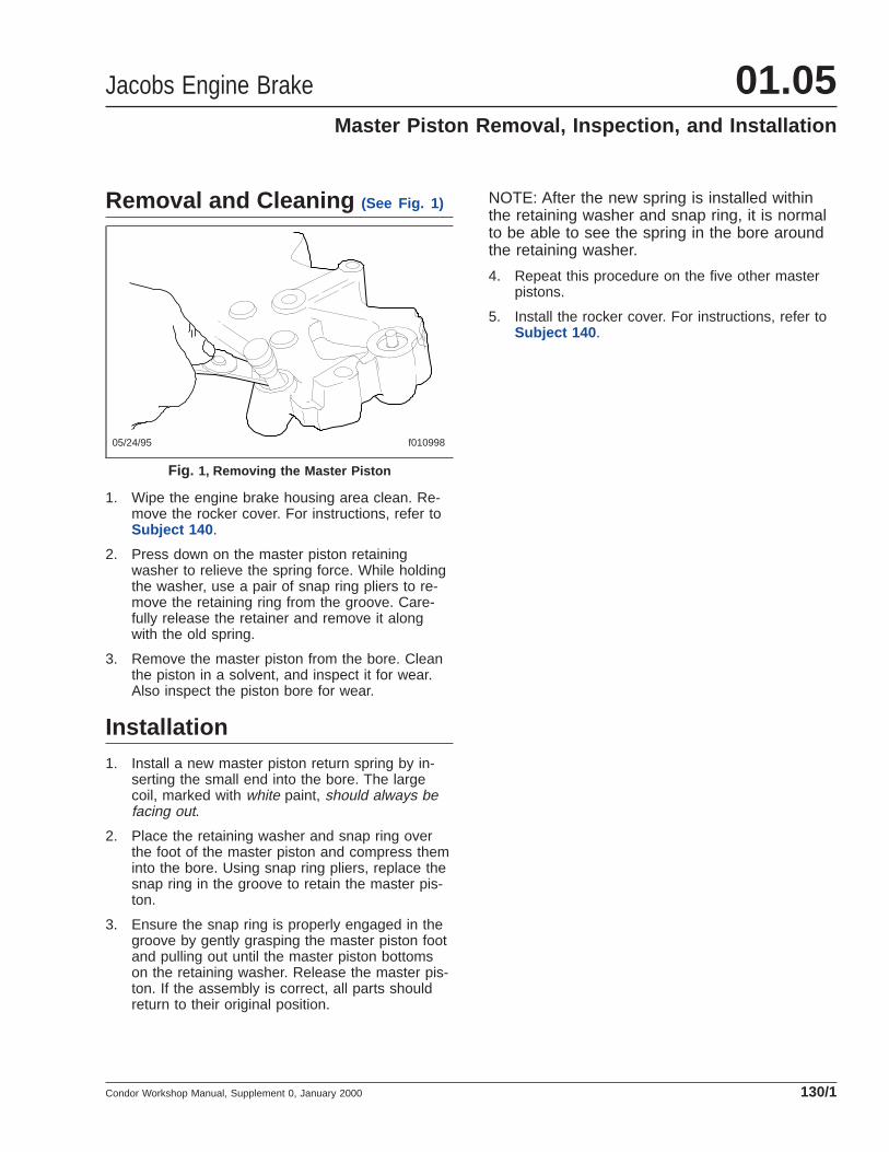
Removal and Cleaning (See Fig. 1)
1. Wipe the engine brake housing area clean. Re-move the rocker cover. For instructions, refer toSubject 140 .
2. Press down on the master piston retainingwasher to relieve the spring force. While holdingthe washer, use a pair of snap ring pliers to re-move the retaining ring from the groove. Care-fully release the retainer and remove it alongwith the old spring.
3. Remove the master piston from the bore. Cleanthe piston in a solvent, and inspect it for wear.Also inspect the piston bore for wear.
Installation1. Install a new master piston return spring by in-
serting the small end into the bore. The largecoil, marked with white paint, should always befacing out.
2. Place the retaining washer and snap ring overthe foot of the master piston and compress theminto the bore. Using snap ring pliers, replace thesnap ring in the groove to retain the master pis-ton.
3. Ensure the snap ring is properly engaged in thegroove by gently grasping the master piston footand pulling out until the master piston bottomson the retaining washer. Release the master pis-ton. If the assembly is correct, all parts shouldreturn to their original position.
NOTE: After the new spring is installed withinthe retaining washer and snap ring, it is normalto be able to see the spring in the bore aroundthe retaining washer.
4. Repeat this procedure on the five other masterpistons.
5. Install the rocker cover. For instructions, refer toSubject 140 .
05/24/95 f010998
Fig. 1, Removing the Master Piston
Jacobs Engine Brake 01.05Master Piston Removal, Inspection, and Installation
Condor Workshop Manual, Supplement 0, January 2000 130/1

Removal (See Fig. 1)
1. Park the vehicle on a level surface, shut downthe engine, apply the parking brakes, and chockthe rear tires.
DANGERBefore tilting the cab or returning the cab to thenormal operating position, read the instructionsand the hazard notices in Section 60.00 . Failureto follow these instructions could cause the cabto fall and hit or crush a person, which will resultin severe injury or death.
2. Tilt the cab.
3. Wipe the engine brake housing area clean.
4. Remove the six bolts that hold each rockercover, and remove the rocker covers.
5. Inspect the cover seals, and replace them if theyare damaged.
Installation
CAUTIONBe sure to tighten all the rocker cover boltsevenly. Excessive or uneven tightening maycause the rocker cover to crack.
1. Make sure a seal is located in the groove ofeach cover, and install the cover on the spacer.Install the six Jacobs’ bolts per cover, and tightenthe bolts 9 lbf·ft (12 N·m).
DANGERBefore tilting the cab or returning the cab to thenormal operating position, read the instructionsand the hazard notices in Section 60.00 . Failureto follow these instructions could cause the cabto fall and hit or crush a person, which will resultin severe injury or death.
2. Return the cab to the normal operating position.
3. Remove the chocks from the tires.
05/24/95 f010996
Fig. 1, Rocker Covers
Jacobs Engine Brake 01.05Rocker Cover Removal and Installation
Condor Workshop Manual, Supplement 0, January 2000 140/1

Removal1. Wipe the engine brake housing area clean. Re-
move the rocker cover. For instructions, refer toSubject 140 .
2. Loosen the slave piston adjusting screw locknut,and remove the adjusting screw from the hous-ing. See Fig. 1 .
Inspection and Installation1. Clean the adjusting screw in an approved sol-
vent.
CAUTIONDo not adjust or tamper with the adjusting screw,engine damage could result.
NOTE: The part number for the screw is locatedat the top of the screw, next to the screwdriverslot. Refer to the manufacturer’s parts manualfor part number identification.
2. Inspect the slave piston adjusting screw. Theplunger should protrude from the bottom of thescrew, should have light spring pressure appar-ent when depressed, and should move freely.See Fig. 2 . Replace the entire screw assembly ifany problem is found.
3. Install the rocker cover. For instructions, refer toSubject 140 .
05/24/95 f010997
Fig. 1, Remove the Adjusting Screw
f010506a12/09/94
Fig. 2, Check the Adjusting Screw Plunger
Jacobs Engine Brake 01.05Slave Piston Adjusting Screw (Power-Lash ™)
Removal, Inspection, and Installation
Condor Workshop Manual, Supplement 0, January 2000 150/1

Removal (See Fig. 1 and Fig. 2)
1. Wipe the engine brake housing area clean. Re-move the rocker cover. For instructions, refer toSubject 140 .
WARNINGThe slave piston is retained by springs that areunder heavy compression. Use the followingtools and instructions or the springs will be dis-charged with enough force to cause personal in-jury.
2. Remove the locknut on the slave piston adjustingscrew. Back out the adjusting screw until theslave piston is fully retracted (the screw is loose).
3. Place the hole in the clamp fixture over the slavepiston adjusting screw. See Fig. 1 .
4. While holding the fixture in position, screw theholder down over the slave piston until the springretainer is contacted.
5. Turn the handle slowly until the retainer is de-pressed to about 1/32 inch (1 mm), relievingpressure against the retaining ring.
6. Remove the retaining ring using retaining ringpliers. Back out the holder until the springs areloose. Remove the fixture.
7. Remove all the components, ensuring there is nobinding or burrs. Clean in an approved cleaningsolvent. Inspect parts and replace as needed.
Installation1. Use the clamp fixture to install the piston and
springs. Be sure the retaining ring is placed onthe retainer before screwing the clamp-holderdown over the slave piston.
2. Compress the slave piston springs down until theretainer is about 1/32 inch (1 mm) below the re-taining ring groove. Install the retaining ring. Besure the retaining ring is fully seated in thegroove.
3. Remove the clamp fixture slowly to ensure cor-rect seating of the retaining ring.
4. Install the rocker cover. For instructions, refer toSubject 140 .
1
2 3
10/27/98 f011521
1. Clamp Fixture2. Locknut3. Slave Piston Adjusting Screw
Fig. 1, Retract the Slave Piston with a Clamp
f011006
1
2
3
4
06/06/2000
1. Slave Piston2. Retaining Ring3. Spring Retainer4. Slave Piston Springs
Fig. 2, Slave Piston Components
Jacobs Engine Brake 01.05Slave Piston Removal and Installation
Condor Workshop Manual, Supplement 0, January 2000 160/1

Removal (See Fig. 1)
1. Wipe the engine brake housing area clean. Re-move the rocker cover. For instructions, refer toSubject 140 .
CAUTIONDo not disassemble or tamper with the solenoidvalve. Engine damage could result. The solenoidvalve is not field serviceable.
2. Disconnect the solenoid harness. Using a 7/8-inch socket and an extension, unscrew the sole-noid valve.
3. Remove and discard the three rubber seal rings.If the lower ring stays in the bottom of the hous-ing bore, remove it with a pick.
Cleaning and Installation1. Wash out the solenoid valve with an approved
solvent. Use a brush to clean the oil screen.When clean, dry the valve with compressed air.
2. Clean out the solenoid valve bore in the housing.Use clean paper towels. Never use rags as theymay leave lint and residue which can plug the oilpassageways.
3. Using new solenoid seal rings, coat them withclean lube oil. Install the upper and center sealrings on the solenoid body, and install the lower
seal ring into the bottom of the solenoid bore inthe housing.
4. Be sure the seals are seated properly and care-fully screw the solenoid into the housing withoutunseating the seals. Tighten the valve 5 lbf·ft (7N·m). Be careful not to twist the seals while in-stalling the solenoid.
5. Install the rocker cover. For instructions, refer toSubject 140 .
f010256a09/20/93
1
2
3
1. Upper Seal2. Center Seal3. Lower Seal
Fig. 1, Solenoid Seals
Jacobs Engine Brake 01.05Solenoid Valve Removal, Cleaning, and Installation
Condor Workshop Manual, Supplement 0, January 2000 170/1

Troubleshooting TablesNOTE: For engine brake service procedures,refer to the applicable section for your model ofengine brake in this workshop manual group.
Problem—Engine Will Not Start
Problem—Engine Will Not Start
Possible Cause Remedy
The solenoid valve is stuck in the "on"position.
Make sure the electrical current to the engine brake is off. If the solenoidvalve stays "on" (cap down) with the current off, replace the solenoidvalve.
Problem—Engine Brake Will Not Function
Problem—Engine Brake Will Not Function
Possible Cause Remedy
An electrical lead is open. Replace any broken wires.
The engine oil pressure is too low. Determine the oil pressure at the engine brake. Refer to the applicablesection in this group for your engine brake. If the oil pressure is belowspecifications, repair the engine following the manufacturer’s procedures.
The throttle switch is malfunctioning. Check for correct operation of the throttle.
Problem—Engine Brake Engages With the Switches Off
Problem—Engine Brake Engages With the Switches Off
Possible Cause Remedy
The solenoid valve center seal ring isdamaged.
Remove the solenoid. Replace all the seal rings.
The engine brake is incorrectly wired. Check the wiring against the Jacobs wiring diagram.
Problem—Engine Brake Weak or Slow to Engage
Problem—Engine Brake Weak or Slow to Engage
Possible Cause Remedy
The lubricating oil is too cold and thick. Allow the engine to warm up before operating the Jake Brake.
The slave piston is adjusted incorrectly or isbinding in its bore. WARNING
Slave piston springs are under heavy compression. Remove the slavepiston carefully when disassembly is necessary. Use either an arborpress or C-clamp. Failure to follow this procedure could result inpersonal injury.Adjust the slave piston. Make sure it responds smoothly to the adjustingscrew—loosen the jam nut and screw the adjusting screw through its fullrange for full slave piston travel. Make sure the piston travels the full rangewithout binding or sticking.
Engine Brake Troubleshooting 01.06Troubleshooting
Condor Workshop Manual, Supplement 0, January 2000 300/1

Problem—Engine Brake Weak or Slow to Engage
Possible Cause Remedy
The solenoid lower seal is damaged, allowingoil to escape the housing.
Remove the solenoid valve and replace all the seal rings.
The solenoid screen is clogged, stopping thesupply of oil to the engine brake.
Remov the solenoid valve; clean or replace the screen.
The master piston is not moving in its bore. Inspect the master piston and bore for scoring or burrs. If any are present,clean the surface with a crocus cloth. If the burrs cannot be removed,replace the piston or housing. Inspect the lubricating oil for signs ofcontaminants. If any are present, replace the oil and filters, and correct thecause of the contamination.
The control valves are binding in the housingbores.
Remove each control valve. If the body is scored, replace the valve. Checkfor contaminants in the lubricating oil. Clean the housing and control valve.If the control valve still binds, replace the housing.
The control valves are malfunctioning. Remove each control valve. Make sure the check ball is seating in thebore and that it can be moved off the seat. Make sure there is springpressure against the ball. Flush the valve in diesel fuel.
Replace the control valve if needed.
Dash switches or throttle switch has sluggishoperation.
Adjust or replace the switch. Check the throttle for proper operation.
The electrical insulation of the solenoid valveis breaking down. WARNING
Do not touch the electrical connections when the engine brakesystem is energized. Touching the connections could possibly causeelectrical shock.Make sure the solenoid valve meets electrical specifications. If not, replacethe solenoid valve.
The engine brake housing plugs are leaking. Check the plugs for signs of leaks. If leaks are found, remove the plugs,clean the threads, and install the plugs. Thread locking compound mayhelp. Tighten the plugs 115 lbf·in (1300 N·cm).
The outer control valve spring is broken, orthe engine oil pressure is extremely high.
Replace the outer control valve spring. Refer to the engine manufacturer’sservice manual for causes of high oil pressure.
The upper solenoid seal ring is damaged,causing oil pressure to drop below theminimum required for engine brake operation.
Remove the solenoid. Inspect the seal rings and replace them if needed.
The oil supply seals under or between thehousings are damaged, causing oil pressureto drop below the minimum required forengine brake operation.
Remove the housings and replace the seals. Check for cracked or brokenoil connectors. Replace the seals.
There is air in the lubricating oil, causing oilpressure to drop below the minimum requiredfor engine brake operation.
Check for aeration of the oil. Turn the engine brake on, then off. Watch theescape oil coming from under the control valve cover. If the oil hasbubbles or is foamy, air is present in the system. Aeration can be causedby an over-or underfilled crankcase, by cracks in the oil pickup tube, or byleaks in the oil suction tube or hose. Refer to the engine manufacturer’sservice manual for corrective measures.
Engine Brake Troubleshooting01.06Troubleshooting
Condor Workshop Manual, Supplement 0, January 2000300/2

Problem—Engine Brake Weak or Slow to Engage
Possible Cause Remedy
The lubricating oil is being diluted by dieselfuel, causing oil pressure to drop below theminimum required for engine brake operation.
Have the lubricating oil analyzed to determine if fuel is present. Refer tothe engine manufacturer’s service manual for corrective measures.
The engine oil level is low, causing oilpressure to drop below the minimum requiredfor engine brake operation.
Refer to the engine manufacturer’s service manual for specifications. Addoil or recalibrate the dipstick as required.
The engine rocker arm bushings are worn,causing oil pressure to drop below theminimum required for engine brake operation.
Replace the bushings. Refer to the engine manufacturer’s service manualfor instructions.
Oil is leaking around the cylinder heads,causing oil pressure to drop below theminimum required for engine brake operation.
Repair the cause of the leaks. Refer to the engine manufacturer’s servicemanual for instructions.
Restrictions in the oil passage leading to theengine brake are causing oil pressure to dropbelow the minimum required for engine brakeoperation.
Inspect all the passageways; remove anything restricting the oil flow.
Problem—Engine Stalls or One or More Cylinders Continue Braking With the Dash Switches Off
Problem—Engine Stalls or One or More Cylinders Continue Braking With the Dash Switches Off
Possible Cause Remedy
The control valve inner spring is broken. Replace the inner spring.
One or more control valves are stuck in the"on" (up) position.
Check the control valves for binding. Remove and clean or replace them ifnecessary. Inspect the lubrication oil for contaminants.
The solenoid valve is sticking in the "on"position.
If the solenoid valve cap remains down with no electric current beingsupplied, replace the solenoid valve.
The center solenoid seal ring is damaged,allowing oil to enter the engine brake with thesolenoid valve closed.
Remove the solenoid and replace all the seal rings.
The solenoid valve exhaust is plugged. Remove any restrictions at the exhaust (bottom) of the solenoid valve.
The dash switch is stuck in the "on" position. Check for correct switch operation. Replace the switch as needed.
Problem—Engine Misses or Loses Power
Problem—Engine Misses or Loses Power
Possible Cause Remedy
The slave piston is adjusted too tight. Adjust the slave piston. Refer to the applicable section in this group for thecorrect engine brake model.
Engine Brake Troubleshooting 01.06Troubleshooting
Condor Workshop Manual, Supplement 0, January 2000 300/3

Problem—Sudden Drop in Engine Lubrication Oil Pressure
Problem—Sudden Drop in Engine Lubrication Oil Pressure
Possible Cause Remedy
The oil inlet supply seal is missing ordamaged.
Replace the seal.
The upper solenoid valve seal is missing ordamaged.
Remove the solenoid and replace all the seal rings.
The external oil supply hoses or fittings arecracked and leaking.
Inspect all hoses and fittings for tightness, chafing, or cuts.
Engine Brake Troubleshooting01.06Troubleshooting
Condor Workshop Manual, Supplement 0, January 2000300/4

General Information
WARNINGDo not use the exhaust retarder brake if road sur-faces are slippery. Using the exhaust retarder onwet, icy, or snow-covered roads could result inloss of vehicle control, possibly causing personalinjury and property damage.
The Pacbrake exhaust brake is an auxiliary brakingdevice that greatly increases the stopping power ofyour vehicle. By using the exhaust brake at everyopportunity your brakes stay cooler reducing the riskof brake fade and "run-away". The principal of theexhaust brake is to capture the exhaust pressure andhold it in the cylinders, which creates resistanceagainst the pistons of the engine. This resistancetranslates through the engine into the driveline andout to the drive wheels causing the vehicle to decel-erate. The exhaust brake uses a butterfly valve thatis attached directly to the outlet of the turbocharger.When activated the butterfly closes, restricting theexhaust gas. In essence the engine is convertedfrom energy production to energy absorbing. The ex-haust brake assembly is attached directly to the en-gine turbocharger.
Since the exhaust retarder is most effective at 300RPM above the rated governed engine speed, gearselection is very important. Gearing down the vehiclewithin the limits of the rated engine speed makes theexhaust retarder more effective. Maximum brakingoccurs with the use of the lowest gear that does notexceed the rated engine speed. A rule of thumb forgear choice is to select the gear that normally wouldbe used to climb an approaching downhill grade.Generally, this same gear can be used with the ex-haust retarder for a controlled descent of the hill.
If the vehicle is equipped with an Allison World MDseries transmission, the exhaust retarder is inter-faced with the transmission ECU. When exhaust re-tarder operation is requested, a signal is sent to thetransmission ECU. This signal tells the transmissionECU that the exhaust retarder is requested and toprovide converter lock-up in second through sixthgears. In addition the ECU will operate in the pre-select downshift mode, allowing for increased brakingby preselecting a lower transmission range, depend-ing on vehicle road speed.
"Control speed" is the speed at which the exhaustretarder performs 100 percent of the required down-hill braking, resulting in a constant speed of descent.The control speed varies, depending on vehicleweight and the downhill grade.
For faster descent, select a higher gear than thatused for control speed. Service brakes must then beused intermittently to prevent engine overspeed andto maintain desired vehicle speed.
A driver may descend slower than control speed byselecting a lower gear, but one that will not over-speed the engine. The exhaust retarder retardingforce will then be sufficient to cause vehicle decel-eration. Occasional deactivation of the exhaust re-tarder may be necessary to maintain the designatedroad speed under these conditions.
WARNINGUsing the exhaust retarder as a primary brakingsystem when the service brakes are operable isdangerous. This can cause long, unpredictablestopping distances, possibly resulting in per-sonal injury or property damage.
Whenever vehicle braking is required, the exhaustretarder may be used with the service brakes. Thereis no time limit for operation of the exhaust retarder .
The exhaust retarder activates when the dash switchis in ON position and the driver’s feet are removedfrom the throttle pedal. Refer to the service informa-tion available from the manufacturer for instructions.
To obtain maximum retarding, maintain the top gov-erned speed of the engine through appropriate selec-tion of gears when the exhaust retarder is in use.
Pacbrake Exhaust Brake 01.07General Information
Condor Workshop Manual, Supplement 0, January 2000 050/1

Removal (See Fig. 1)
1. Park the vehicle on a level surface, shut downthe engine, apply the parking brakes, and chockthe rear tires.
DANGERBefore tilting the cab or returning the cab to thenormal operating position, read the instructionsand hazard notices in Section 60.00 of this work-shop manual. Failure to follow these instructionscould cause the cab to fall and hit or crush a per-son, which will result severe injury or death.
2. Tilt the cab.
3. Drain the air system.
4. Disconnect the air line from the exhaust brake.
5. Loosen the exhaust clamps at the turbochargerand below the exhaust brake.
NOTE: It may be necessary to loosen the ex-haust system mounting brackets to remove theexhaust brake.
6. Remove the exhaust brake and cover the turbo-charger opening.
Installation1. Install the exhaust brake to the turbocharger.
2. Install the section of exhaust ducting that runsbetween the exhaust brake and the muffler.
3. Connect the air line to the exhaust brake.
4. Tighten all exhaust clamps.
DANGERBefore tilting the cab or returning the cab to thenormal operating position, read the instructionsand hazard notices in Section 60.00 of this work-shop manual. Failure to follow these instructionscould cause the cab to fall and hit or crush a per-son, which will result severe injury or death.
5. Return the cab to the normal operating position.
6. Remove the chocks from the tires.
10/25/99 f011718
1
2
3
4
3
5
1. Air Line2. Pacbrake Exhaust Brake3. Clamp4. Turbocharger5. Exhaust Pipe
Fig. 1, Pacbrake Exhaust Brake Mounting
Pacbrake Exhaust Brake 01.07Pacbrake Exhaust Brake Removal and Installation
Condor Workshop Manual, Supplement 0, January 2000 100/1
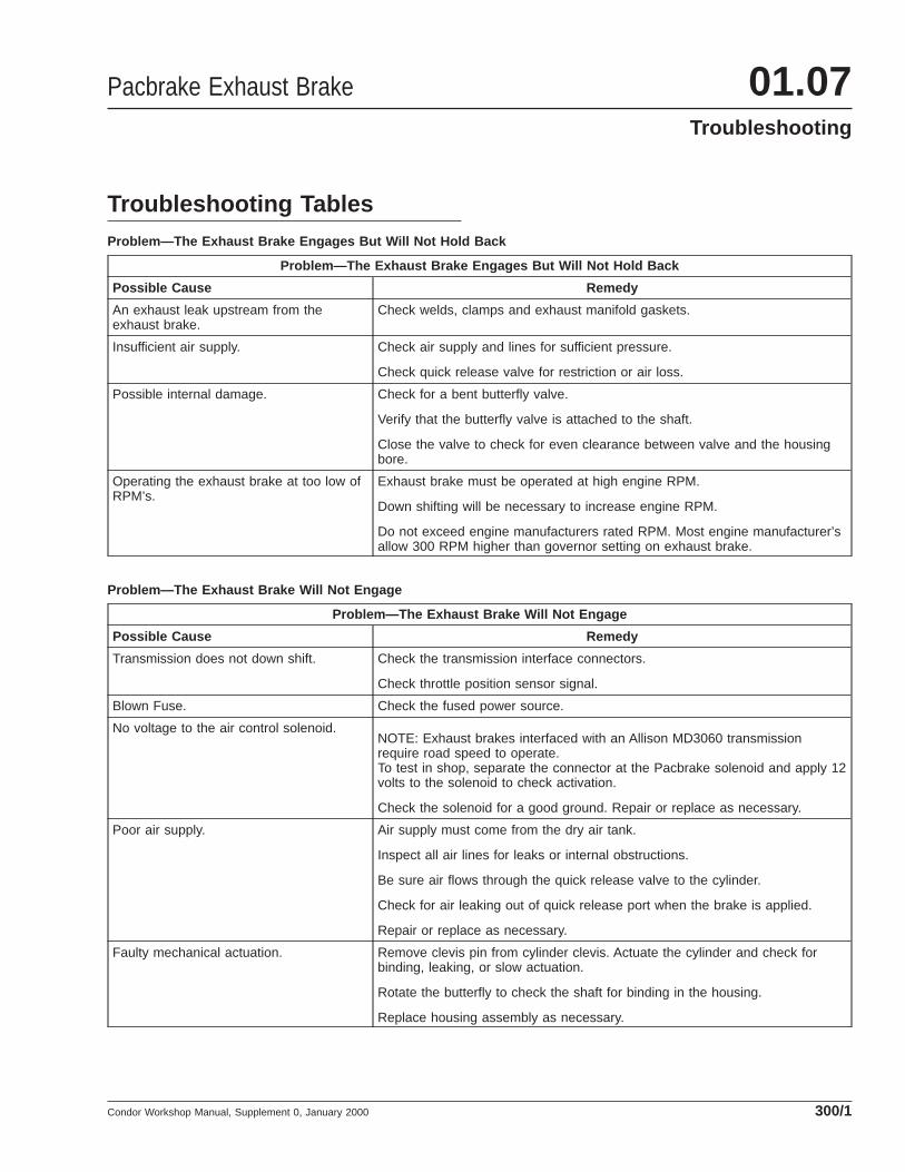
Troubleshooting TablesProblem—The Exhaust Brake Engages But Will Not Hold Back
Problem—The Exhaust Brake Engages But Will Not Hold Back
Possible Cause Remedy
An exhaust leak upstream from theexhaust brake.
Check welds, clamps and exhaust manifold gaskets.
Insufficient air supply. Check air supply and lines for sufficient pressure.
Check quick release valve for restriction or air loss.
Possible internal damage. Check for a bent butterfly valve.
Verify that the butterfly valve is attached to the shaft.
Close the valve to check for even clearance between valve and the housingbore.
Operating the exhaust brake at too low ofRPM’s.
Exhaust brake must be operated at high engine RPM.
Down shifting will be necessary to increase engine RPM.
Do not exceed engine manufacturers rated RPM. Most engine manufacturer’sallow 300 RPM higher than governor setting on exhaust brake.
Problem—The Exhaust Brake Will Not Engage
Problem—The Exhaust Brake Will Not Engage
Possible Cause Remedy
Transmission does not down shift. Check the transmission interface connectors.
Check throttle position sensor signal.
Blown Fuse. Check the fused power source.
No voltage to the air control solenoid.NOTE: Exhaust brakes interfaced with an Allison MD3060 transmissionrequire road speed to operate.To test in shop, separate the connector at the Pacbrake solenoid and apply 12volts to the solenoid to check activation.
Check the solenoid for a good ground. Repair or replace as necessary.
Poor air supply. Air supply must come from the dry air tank.
Inspect all air lines for leaks or internal obstructions.
Be sure air flows through the quick release valve to the cylinder.
Check for air leaking out of quick release port when the brake is applied.
Repair or replace as necessary.
Faulty mechanical actuation. Remove clevis pin from cylinder clevis. Actuate the cylinder and check forbinding, leaking, or slow actuation.
Rotate the butterfly to check the shaft for binding in the housing.
Replace housing assembly as necessary.
Pacbrake Exhaust Brake 01.07Troubleshooting
Condor Workshop Manual, Supplement 0, January 2000 300/1

Problem—The Exhaust Brake Will Not Disengage
Problem—The Exhaust Brake Will Not Disengage
Possible Cause Remedy
Faulty air release valve. Air release from quick release valve. Replace if necessary.
Air release from exhaust port of solenoid. Replace if necessary.
Check all air lines for restrictions. Repair or replace as necessary.
Check cylinder breather for blockage. Replace if necessary.
Blown Fuse. Check the fused power source.
No voltage to the air control solenoid.NOTE: Exhaust brakes interfaced with an Allison MD3060 transmissionrequire road speed to operate.To test in shop, separate the connector at the Pacbrake solenoid and apply 12volts to the solenoid to check activation.
Check the solenoid for a good ground. Repair or replace as necessary.
Poor air supply. Air supply must come from the dry air tank.
Inspect all air lines for leaks or internal obstructions.
Be sure air flows through the quick release valve to the cylinder.
Check for air leaking out of quick release port when the brake is applied.
Repair or replace as necessary.
Faulty mechanical actuation. Remove clevis pin from cylinder clevis. Actuate the cylinder and check forbinding, leaking, or slow actuation.
Rotate the butterfly to check the shaft for binding in the housing.
Replace housing assembly as necessary.
Pacbrake Exhaust Brake01.07Troubleshooting
Condor Workshop Manual, Supplement 0, January 2000300/2

General InformationA bypass oil filter is a remote-mounted oil filterplumbed to the engine. Not all of the engine oil runsthrough a bypass filter, the filter bleeds some of theoil from the engine, the rest of the oil "bypasses" thefilter and stays within the engine.
Normal engine operation produces a variety of con-taminants such as resins, gums, and acids. The by-pass oil filter -- sometimes used with a full-flow filter(an engine-mounted filter that all the oil must runthrough) -- traps these contaminants and preventsexcessive wear of engine parts. The filtered oil thenreturns to the engine crankcase or sump.
American LaFrance uses the following models ofbypass oil filters:
• Fleetguard® Model LF 750™
• Luber-finer® Model 750-CT
• Spinner II®
Fleetguard Model LF 750 (See Fig. 1)
Engine oil enters the Fleetguard Model LF 750through the inlet check valve and fills the filter hous-ing around the filter element. Oil pressure within thehousing builds until oil is forced through the filter. In-side the filter, the filtered oil moves through openingsin the filter hold-down assembly, and collects in the
outlet tube. From the outlet tube, the oil goes back tothe engine through the outlet check valve assembly.
An engine equipped with the Model LF 750 needs 3gallons (11.3 liters) more oil than an engine without abypass oil filter.
Luber-finer Model 750-CT (See Fig. 2
and Fig. 3 )
To prevent thick, cold oil from clogging the filter, athermostat within the Luber-finer model 750-CT al-lows engine oil to flow through the filter only after theoil has warmed to a specified temperature. The ther-mostat is inside the T-handle assembly that holds thefilter pack in place.
Engine oil enters through the inlet check valve as-sembly on the bottom of the filter housing, and fillsthe filter housing around the filter pack (element).Inside the housing, oil pressure forces the oil throughthe sides of the filter pack. Inside the filter pack, fil-
05/03/95 f010957
Fig. 1, Fleetguard Model LF 750 Bypass Oil Filter
04/26/95 f010948
Fig. 2, Luber-finer Model 750-CT Bypass Oil Filter
Bypass Oil Filter 01.08General Information
Condor Workshop Manual, Supplement 0, January 2000 050/1

tered oil travels through openings in the T-handlehold-down assembly, then collects in the outlet tube.From the outlet tube, filtered oil goes back to the en-gine through the outlet check valve assembly.
The inlet and outlet valves normally have #8 orifices.
Normal continuous operating oil pressure is about 65psi (448 kPa). An engine equipped with the Model750-CT needs 3 1/2 gallons (13.2 liters) more oilthan an engine without a bypass oil filter. Flow ratethrough the filter is about 1 or 2 gallons (3.7 or 7.5liters) per minute at normal operating pressure.
Spinner II (See Fig. 4 and Fig. 5)
The Spinner II uses centrifugal force to separate con-taminants from the oil, and uses air pressure to forcethe filtered oil back to the engine.
Engine oil enters the top half of the filter housing,and travels up through a spindle in the center of acylindrical centrifuge turbine lined with an optionalpaper lining. At the same time, the pressure of the oilentering the filter housing makes the centrifuge spin.The oil sprays out of the top of the spindle, and thecentrifugal force of the spinning centrifuge drives theoil contaminants against the inside of the centrifugeturbine. The contaminants cake inside the centrifugeturbine, and the clean oil runs into the bottom half ofthe filter housing.
The clean oil collects in the bottom half of the filterhousing where it lifts a float. The float opens a valvethat allows brake system air to enter the housing,and the air pressure forces the cleaned oil out of thehousing and back to the engine.
Normal continuous operating oil pressure is about 60psi (413.6 kPa). An engine equipped with the SpinnerII doesn’t need any extra oil. Flow rate through thecleaner is about 2 gallons (7.5 liters) per minute atnormal operating pressure.
06/16/95 f010108a
12
3
4
5
6
7
8
910 11
12
13
14
15
1. Vent Plug Capscrew2. Washer3. T-Handle4. Cover5. Cover Gasket6. Housing7. Filter Element8. Outlet Tube9. Drain Cock
10. Outlet Check ValveAssembly
11. Inlet Check ValveAssembly
12. Mounting Bracket13. Clamping Ring14. Clamp-Ring
Capscrew15. Hold-Down Assembly
Fig. 3, Luber-finer Model 750-CT (sectional view)
Bypass Oil Filter01.08General Information
Condor Workshop Manual, Supplement 0, January 2000050/2

05/10/95 f010949
1
A
B
C
A. Oil OutB. Air In
C. Oil In
1. Air Valve Cartridge Seal
Fig. 4, Spinner II Bypass Oil Filter
04/28/95 f010955
Fig. 5, Spinner II Bypass Oil Filter (sectional view)
Bypass Oil Filter 01.08General Information
Condor Workshop Manual, Supplement 0, January 2000 050/3

Replacement (See Fig. 1)
IMPORTANT: Do the following at every sched-uled engine oil change. Refer to the enginemaintenance manual for the quantity of oil thatmust be added to the lubrication system whenreplacing the bypass filter.
1. Remove the oil filter element.
1.1 Remove the drain plug and allow the oilto drain.
1.2 Remove the clamp-ring capscrews. Re-move the clamp ring and lift the cover offthe filter housing.
1.3 Unscrew the hold-down assemblyT-handle and remove the assembly fromthe housing. Check the O-ring and springfor damage. Replace if needed.
1.4 Remove and discard the oil filter element.
2. Clean the inside of the housing, and the hold-down assembly, with solvent.
3. Assemble the filter.
3.1 Install the drain plug.
3.2 Install a new filter element.
3.3 Install the hold-down assembly and se-curely tighten the T-handle.
3.4 Check the cover gasket for damage, andreplace it if needed. Position the gasketon the housing.
3.5 Position the cover on the housing. Installthe clamp ring and capscrews. Alternatelytighten the capscrews to ensure a uniformseal between the cover and gasket.
3.6 Start the engine and let it idle until normaloperating oil pressure is reached.
CAUTIONMake sure the engine oil level is correct. Operat-ing the engine with the oil level below the low("L") mark, or above the high mark, could resultin engine damage.
3.7 Add oil as needed to bring the oil level upto the high ("H") mark on the dipstick.
06/30/95 f010109a
1 2
3
4
5
6 7
8
9
10
11
12
1. Clamp Ring2. Clamp-Ring Capscrew3. Cover4. Cover Gasket
5. T-Handle6. O-Ring7. Spring8. Filter Element
9. Housing10. Inlet Check Valve Assembly11. Outlet Tube12. Retaining Ring
Fig. 1, Fleetguard Model LF 750 (exploded view)
Bypass Oil Filter 01.08Oil Filter Element Replacement, Fleetguard ® Model
LF 750™
Condor Workshop Manual, Supplement 0, January 2000 100/1

Replacement (See Fig. 1)
IMPORTANT: Do the following procedure at ev-ery scheduled engine oil change. Refer to theengine maintenance manual for the quantity ofoil that must be added to the lubrication systemwhen replacing the bypass filter.
1. Remove the old filter element.
1.1 Loosen the vent plug capscrew, thenopen the drain cock and allow the oil todrain.
1.2 Remove the clamp-ring capscrews. Re-move the clamp ring and lift the cover offthe filter housing.
1.3 Unscrew the hold-down assemblyT-handle and remove the assembly fromthe housing.
1.4 Remove and discard the oil filter element.
2. Clean the inside of the housing, and the hold-down assembly, with solvent.
3. Assemble the filter.
3.1 Close the drain cock.
3.2 Install a new filter element.
3.3 Check the cover gasket for damage, andreplace it if needed.
3.4 Install the hold-down assembly and se-curely tighten the T-handle.
3.5 Position the cover on the housing. Installthe clamp ring and capscrews. Alternatelytighten the clamp capscrews to ensure auniform seal between the cover and gas-ket.
3.6 Add oil to the crankcase, then start theengine and let it idle until normal operat-ing oil pressure is reached.
3.7 Loosen the vent plug capscrew and bleedany trapped air from the filter housing.Tighten the vent plug capscrew as soonas oil appears at the fitting.
CAUTIONMake sure the engine oil level is correct. Operat-ing the engine with the oil level below the low("L") mark, or above the high mark, could resultin engine damage.
4. Shut down the engine and add oil as needed tobring the oil level up to the high ("H") mark onthe dipstick.
06/16/95 f010108a
12
3
4
5
6
7
8
910 11
12
13
14
15
1. Vent Plug Capscrew2. Washer3. T-Handle4. Cover5. Cover Gasket6. Housing7. Filter Element8. Outlet Tube9. Drain Cock
10. Outlet Check ValveAssembly
11. Inlet Check ValveAssembly
12. Mounting Bracket13. Clamping Ring14. Clamp-Ring
Capscrew15. Hold-Down Assembly
Fig. 1, Luber-finer Model 750-CT Bypass Oil Filter
Bypass Oil Filter 01.08Oil Filter Element Replacement, Luber-finer ® Model
750-CT
Condor Workshop Manual, Supplement 0, January 2000 110/1

Cleaning (See Fig. 1)
IMPORTANT: Do the following procedure at ev-ery scheduled engine oil change. Refer to theengine maintenance manual for the quantity ofoil that must be added to the lubrication systemwhen replacing the bypass filter.
1. Clean the centrifuge bowl.
1.1 Shut off the engine, and let the centrifugeturbine assembly come to a completestop.
1.2 Loosen the handle on the clamp, disen-gage the tee bolt and remove the cover,using a coin in the gap to separate thecover from the housing.
1.3 Partially withdraw the centrifuge turbineassembly from the housing and allow oilto drain from the nozzles before removingthe assembly completely.
1.4 Hold the centrifuge turbine assembly inone hand and loosen the knurled nut sev-eral turns until the face of the nut projectsbeyond the bronze bushing face.
1.5 Carefully separate the centrifuge bowlfrom the turbine base by striking the faceof the nut with the palm of one hand
while holding the bowl in the other. Donot strike the nut or the bushing with oragainst a hard surface or you will damagethem. Finish removing the nut and thenremove the bowl and baffle/screen.
1.6 Replace the dirty centrifuge bowl with anew one, or carefully remove the cake ofdirt from the bowl with a wooden spatulaor other non-damaging tool. Wipe out thebowl with solvent
NOTE: To save time cleaning the bowl, anoptional die-cut Bristol paper insert is avail-able for lining the bowl so the compressedcake of dirt can be removed quickly.
1.7 Wash the baffle/screen and turbine base,removing and discarding the black Nitrilebowl seal.
2. Inspect and assemble the centrifuge turbine as-sembly.
2.1 Inspect the top and bottom bushings ofthe centrifuge turbine base, and replacethe turbine assembly if the bushings showsevere wear.
05/10/95 f010952
1 2 3
4
5 6
7 8
9 10 11 12 13
14 15
1. Cover2. Clamp3. Cover Seal4. Nut, Centrifuge Bowl5. Centrifuge Bowl
6. Seal, Centrifuge Bowl7. Paper Insert8. Baffle/Screen9. Centrifuge Turbine10. Housing Assembly
11. Capscrew, M10 x 35 mm12. Seal, Control Mechanism13. Control Mechanism14. Air Valve Cartridge Assembly15. Seal, Air Valve Cartridge
Fig. 1, Spinner II Bypass Oil Filter
Bypass Oil Filter 01.08Centrifuge Bowl Cleaning, Spinner II ®
Condor Workshop Manual, Supplement 0, January 2000 120/1

2.2 Place the baffle/screen over the stem ofthe turbine base and seat the baffle/screen evenly over the shoulder on thebase.
2.3 Install the bowl seal in the recess in theouter edge of the turbine base.
2.4 Slide a new centrifuge bowl over the stemand seat it uniformly over the bowl seal.
2.5 Install and tighten the knurled bowl nutsecurely, using finger pressure only.
3. Clean and inspect the oil filter housing.
3.1 Inspect the housing assembly, payingspecial attention to the journal areas ofthe spindle.
3.2 Clean and inspect the cover.
3.3 Remove the old cover seal, and clean thegroove in the housing and the mating sur-face of the cover.
3.4 Replace the cover seal with a new blackNitrile seal.
4. Check the air valve control mechanism. SeeFig. 2 .
4.1 Make a hook out of stiff wire, according tothe measurements in Fig. 2 .
4.2 Insert the hook at the spot shown inFig. 2 , and hook the float arm.
Lifting the float should release air into thefilter housing.
Lowering the float should stop the flow ofair into the filter housing.
5. Install the centrifuge turbine assembly.
5.1 Install the centrifuge turbine assembly,and make sure it rotates freely.
5.2 Replace the cover, and position the clampuniformly over the cover and housingflanges.
5.3 Tighten the clamp handle securely byhand pressure only.
6. With the engine running, check all the oil filterconnections and joints for leaks.
DS
f01096705/10/95
1
2
A
B
C
NOTE: This is a view, downward into the housing as-sembly, with the centrifuge turbine assembly removed.A. Use the hook at this point to hook the float arm.B. 3/8 Inch (10 mm)C. 9 Inches (229 mm)1. Manufacturer Date Code2. Hook
Fig. 2, Check The Air Valve
Bypass Oil Filter01.08Centrifuge Bowl Cleaning, Spinner II ®
Condor Workshop Manual, Supplement 0, January 2000120/2

General InformationThe AMOT intake air shutoff valve (see Fig. 1 ) is abutterfly-type valve (see Fig. 2 ) that is in the intakeair duct. The intake air shutoff valve is used as anemergency engine shutoff and provides positive en-gine shutdown by closing the engine air intake andstopping the flow of air to the engine. This is impor-tant in situations where combustible vapors may bepresent in the intake air that would allow the engineto continue running with the fuel shut off.
The butterfly valve is normally held in the open posi-tion in the intake air duct. When the emergency en-gine shutdown switch on the left portion of the centerdash is activated, a solenoid releases the valve con-trol mechanism and closes the flapper valve acrossthe intake air duct, stopping the flow of air. Thiscauses the engine to shutdown.
There are two types of AMOT engine stop systems,manual and automatic. After the intake air shutoffvalve has been activated on manual reset systems,the air-restriction filter minder and the AMOT intakeair shutoff valve must be reset. On automatic resetsystems, only the air-restriction filter minder must bereset after activation.
After the intake air shutoff valve has been activated,the air-restriction filter minder must be reset. Onmanual type systems, the AMOT intake air shutoffvalve must also be reset.
10/01/97 f011138
12
3
1. Valve Mechanism2. Control Handle3. Intake Air Ducting
Fig. 1, AMOT Intake Air Shutoff Valve (manual resettype shown)
f011139
1
10/22/97
2
1. Flapper Valve2. O-Ring
Fig. 2, AMOT Intake Air Shutoff Valve (inside view)
AMOT Engine Stop 01.09General Information
Condor Workshop Manual, Supplement 0, January 2000 050/1

Replacement (See Fig. 1)
1. Park the vehicle on a level surface, shut downthe engine, apply the parking brakes, and chockthe rear tires.
DANGERBefore tilting the cab or returning the cab to thenormal operating position, read the instructionsand hazard notices in Section 60.00 of this work-shop manual. Failure to follow these instructionscould cause the cab to fall and hit or crush a per-son, which will result severe injury or death.
2. Tilt the cab.
3. Remove the electrical connector from the AMOTintake air shutoff valve solenoid.
4. Loosen the worm clamps and slid them awayfrom the AMOT intake air shutoff valve.
5. Remove the air intake hose from the rear of theAMOT intake air shutoff valve.
6. Remove the AMOT intake air shutoff valve.
7. Position the new AMOT intake air shutoff valve inthe air intake ducting with the valve operator onthe top.
8. Attach the air intake hose to the rear of theAMOT intake air shutoff valve.
9. Slide the worm clamps to the edge of the air in-take hose closest to the AMOT intake air shutoffvalve and tighten them.
10. Install the electrical connector into the AMOT in-take air shutoff valve solenoid.
DANGERBefore tilting the cab or returning the cab to thenormal operating position, read the instructionsand hazard notices in Section 60.00 of this work-shop manual. Failure to follow these instructionscould cause the cab to fall and hit or crush a per-son, which will result severe injury or death.
11. Return the cab to the normal operating position.
12. Start the engine and test the AMOT intake airshutoff valve.
13. Reset the air-restriction filter minder and theAMOT intake air shutoff valve. Refer to Sub-ject 120 for instructions.
14. Remove the chocks.
10/01/97 f011138
12
3
1. Valve Mechanism2. Control Handle3. Intake Air Ducting
Fig. 1, AMOT Intake Air Shutoff Valve (manual resettype shown)
AMOT Engine Stop 01.09AMOT Intake Air Shutoff Valve Replacement
Condor Workshop Manual, Supplement 0, January 2000 100/1
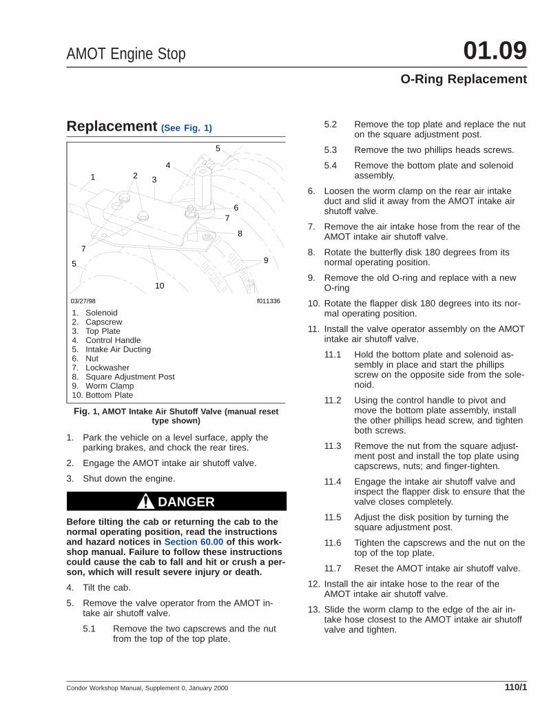
Replacement (See Fig. 1)
1. Park the vehicle on a level surface, apply theparking brakes, and chock the rear tires.
2. Engage the AMOT intake air shutoff valve.
3. Shut down the engine.
DANGERBefore tilting the cab or returning the cab to thenormal operating position, read the instructionsand hazard notices in Section 60.00 of this work-shop manual. Failure to follow these instructionscould cause the cab to fall and hit or crush a per-son, which will result severe injury or death.
4. Tilt the cab.
5. Remove the valve operator from the AMOT in-take air shutoff valve.
5.1 Remove the two capscrews and the nutfrom the top of the top plate.
5.2 Remove the top plate and replace the nuton the square adjustment post.
5.3 Remove the two phillips heads screws.
5.4 Remove the bottom plate and solenoidassembly.
6. Loosen the worm clamp on the rear air intakeduct and slid it away from the AMOT intake airshutoff valve.
7. Remove the air intake hose from the rear of theAMOT intake air shutoff valve.
8. Rotate the butterfly disk 180 degrees from itsnormal operating position.
9. Remove the old O-ring and replace with a newO-ring
10. Rotate the flapper disk 180 degrees into its nor-mal operating position.
11. Install the valve operator assembly on the AMOTintake air shutoff valve.
11.1 Hold the bottom plate and solenoid as-sembly in place and start the phillipsscrew on the opposite side from the sole-noid.
11.2 Using the control handle to pivot andmove the bottom plate assembly, installthe other phillips head screw, and tightenboth screws.
11.3 Remove the nut from the square adjust-ment post and install the top plate usingcapscrews, nuts; and finger-tighten.
11.4 Engage the intake air shutoff valve andinspect the flapper disk to ensure that thevalve closes completely.
11.5 Adjust the disk position by turning thesquare adjustment post.
11.6 Tighten the capscrews and the nut on thetop of the top plate.
11.7 Reset the AMOT intake air shutoff valve.
12. Install the air intake hose to the rear of theAMOT intake air shutoff valve.
13. Slide the worm clamp to the edge of the air in-take hose closest to the AMOT intake air shutoffvalve and tighten.
f011336
14
32
5
7
5
03/27/98
10
9
8
76
1. Solenoid2. Capscrew3. Top Plate4. Control Handle5. Intake Air Ducting6. Nut7. Lockwasher8. Square Adjustment Post9. Worm Clamp10. Bottom Plate
Fig. 1, AMOT Intake Air Shutoff Valve (manual resettype shown)
AMOT Engine Stop 01.09O-Ring Replacement
Condor Workshop Manual, Supplement 0, January 2000 110/1

DANGERBefore tilting the cab or returning the cab to thenormal operating position, read the instructionsand hazard notices in Section 60.00 of this work-shop manual. Failure to follow these instructionscould cause the cab to fall and hit or crush a per-son, which will result severe injury or death.
14. Return the cab to the normal operating position.
15. Start the engine and test the AMOT intake airshutoff valve.
16. Reset the air-restriction filter minder and theAMOT intake air shutoff valve. Refer to Sub-ject 120 for instructions.
17. Remove the chocks.
AMOT Engine Stop01.09O-Ring Replacement
Condor Workshop Manual, Supplement 0, January 2000110/2

Manual Type1. Place the engine emergency shutdown switch in
the "OFF" position.
2. Park the vehicle on a level surface, shut downthe engine, apply the parking brakes, and chockthe rear tires.
DANGERBefore tilting the cab or returning the cab to thenormal operating position, read the instructionsand hazard notices in Section 60.00 of this work-shop manual. Failure to follow these instructionscould cause the cab to fall and hit or crush a per-son, which will result severe injury or death.
3. Tilt the cab.
4. While standing on the righthand side of the ve-hicle, pull the valve handle toward you. This al-lows the engine to be restarted. See Fig. 1 andFig. 2 . The valve will not reset, however, unlessthe engine emergency shutdown switch is disen-gaged with the electrical power on.
5. Reset the air-restrictor filter minder mounted onthe air intake ducting by pushing on the bottomof the device. See Fig. 3 .
DANGERBefore tilting the cab or returning the cab to thenormal operating position, read the instructionsand hazard notices in Section 60.00 of this work-shop manual. Failure to follow these instructionscould cause the cab to fall and hit or crush a per-son, which will result severe injury or death.
f011137
1
2
3
10/10/97
1. Valve Mechanism2. Control Handle3. Air Intake Ducting
Fig. 1, AMOT Valve (closed position)
10/01/97 f011138
12
3
1. Valve Mechanism2. Control Handle3. Air Intake Ducting
Fig. 2, AMOT Valve (open position)
10/01/97 f011140
Fig. 3, Air-Restriction Filter Minder
AMOT Engine Stop 01.09AMOT Intake Air Shutoff Valve Resetting
Condor Workshop Manual, Supplement 0, January 2000 120/1

6. Return the cab to the normal operating position.
7. Start the engine and check for normal operation.
8. Remove the chocks.
Automatic Type1. Place the engine emergency shutdown switch is
in the "OFF" position.
2. Park the vehicle on a level surface, shut downthe engine, apply the parking brakes, and chockthe rear tires.
3. Open the rear tunnel access door located in therear of the cab.
4. Reset the air-restrictor filter minder mounted onthe air intake ducting by pushing on the bottomof the device. See Fig. 3 .
5. Close and latch the rear tunnel access door.
6. Start the engine and check for normal operation.
7. Remove the chocks.
AMOT Engine Stop01.09AMOT Intake Air Shutoff Valve Resetting
Condor Workshop Manual, Supplement 0, January 2000120/2

Troubleshooting TableProblem—The AMOT Engine Stop Does Not Shut Down the Engine
Problem—The AMOT Engine Stop Does Not Shutdown the Engine
Possible Cause Remedy
Voltage is not present at the AMOTsolenoid while the shut down switch isactivated.
Check the 251 circuit for an open circuit.
Ground is not present at the AMOTsolenoid. Check the GND circuit for an open circuit.
An obstruction in the path of the actuatorhandle. Check the actuator and handle for proper clearance when the cab is lowered.
An obstruction in the air intake at theAMOT valve. Check the air intake at the AMOT valve for an obstruction.
The O-ring is worn. Replace the O-ring.
The butterfly disk is not sealingcompletely. Adjust the butterfly disk so that it closes completely.
AMOT Engine Stop 01.09Troubleshooting
Condor Workshop Manual, Supplement 0, January 2000 300/1

General InformationNOTE: For engine service and troubleshootingprocedures, see the engine manufacturer’s ser-vice literature.
For engine brake information for the Cumminsengines, see Section 01.05 .
For detailed repair procedures and other engine ser-vice not covered in this section, refer to the CumminsOperation and Maintenance Manuals, CumminsTroubleshooting and Repair Manuals, and the Cum-mins Workshop Manuals for your specific engine.
Cummins Engine 01.10General Information
Condor Workshop Manual, Supplement 7, September 2005 050/1

Belt InspectionNOTE: Refer to Fig. 1 during pulley and drivebelt inspections.
1. Inspect all used drive belts (including those thatare being replaced) for the following conditions:
NOTE: For an installed belt, gently twist thebelt about 90 degrees so you can see thesidewalls and bottom.
1.1 Inspect for glazing (shiny sidewalls). Glaz-ing is caused by friction created when aloose belt slips in the pulleys. It can alsobe caused by oil or grease on the pulleys.
1.2 Inspect for separating layers. Oil, grease,or belt dressings can cause the belt to fallapart in layers. If engine parts are leaking,repair the oil leaks. Do not use belt dress-ings on any belt.
1.3 Check for jagged or streaked sidewalls.These are the result of a foreign object(such as sand or small gravel) in the pul-ley, or a rough pulley wall surface.
1.4 Check for tensile breaks (breaks in thecord body). Cuts in a belt are usuallycaused by large foreign objects in the pul-ley, or by prying or forcing the belt duringinstallation or removal.
1.5 On poly-V belts, check for uneven ribs.Foreign objects in the pulley will erode theundercord ribs, causing the belt to lose itsgripping power.
1.6 Inspect for cracks. Small, irregular cracksare usually signs of an old belt.
Replace the belt if any of the above condi-tions are found. Replace both belts of aset, at the same time. Matched belts mustbe from the same manufacturer.
2. Check all pulley bearings for roughness. Replacethe bearings if they’re rough.
3. Inspect all pulleys for foreign objects, oil, orgrease in the grooves. Use a nonflammablecleaning solvent to remove oils. Use a wire brushto remove rust, and a file to remove burrs.
4. Inspect the pulleys for wear on the inner walls.Hold a small straightedge against the inside of
the pulley walls (Fig. 2 ), or use your little fingeror fingernail to find grooves in the inner walls. Ifthere are any grooves, replace the pulley.
5. Check alignment (Fig. 3 ) of pulleys. Use a thinstraightedge that is longer than the longest spanbetween the pulleys. Place the straightedge intothe V-grooves of two pulleys at a time. Thestraightedge should be parallel to the outeredges of the pulleys; if not, the pulleys are mis-aligned.
Pulley misalignment must not be more than 1/16-inch for each foot (1.5 mm for each 30.5 cm) ofdistance between pulley centers.
If there is misalignment of the pulleys, adjust thepulleys or brackets if their positions are adjust-able. Replace bent or broken pulleys, pulleybrackets, or shafts.
6. Check all drive component mounting parts forloose fasteners, cracks, or other damage.Tighten loose fasteners. Repair or replacecracked or damaged brackets.
Cummins Engine 01.10Pulley and Drive Belt Inspection
Condor Workshop Manual, Supplement 7, September 2005 100/1
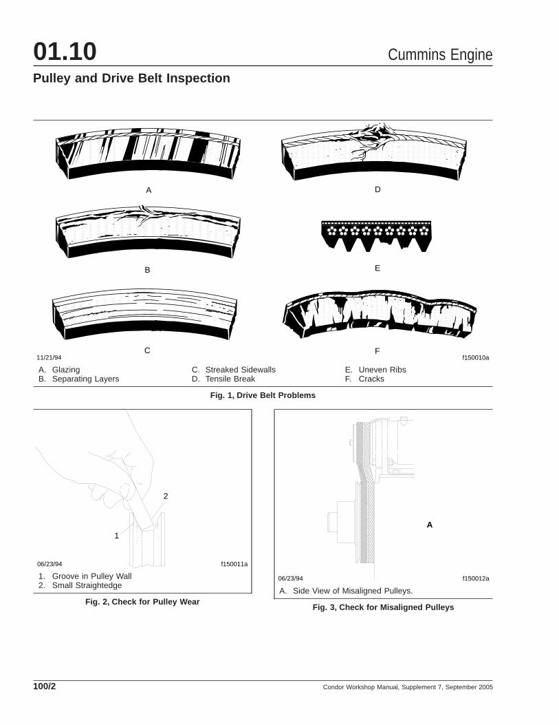
f150010a
A
B
C
D
E
F11/21/94
A. GlazingB. Separating Layers
C. Streaked SidewallsD. Tensile Break
E. Uneven RibsF. Cracks
Fig. 1, Drive Belt Problems
f150011a06/23/94
1
2
1. Groove in Pulley Wall2. Small Straightedge
Fig. 2, Check for Pulley Wear
f150012a06/23/94
A
A. Side View of Misaligned Pulleys.
Fig. 3, Check for Misaligned Pulleys
Cummins Engine01.10Pulley and Drive Belt Inspection
Condor Workshop Manual, Supplement 7, September 2005100/2

Replacement
Alternator1. Remove the belt.
1.1 Loosen the alternator mounting bolt andthe adjustment link locking capscrew justenough to allow movement of the alterna-tor.
1.2 Loosen the adjusting screw locknut.
1.3 Turn the alternator adjusting screw, back-ing off the alternator toward the drive pul-ley far enough to allow belt removal with-out using force.
1.4 Remove the belt, without prying or rollingit off of the pulleys.
2. Install the new belt.
2.1 Inspect the pulleys and used alternatorbelt (even if a new belt is being installed)as instructed in Subject 100 .
2.2 Make sure the distance between the pul-leys is short enough to allow belt installa-tion without using force.
2.3 Install the belt on the pulleys without pry-ing or rolling it into place. Be sure the ribson the belt are seated in the grooves oneach pulley.
2.4 While keeping the belt seated in the pulleygrooves, turn the adjusting screw clock-wise to increase the belt tension. Use yourthumb to apply about 25 lb (11 kg) offorce at the center of the belt free-span tocheck the tension while turning the adjust-ing screw. When belt deflection equalsone belt thickness per foot (305 mm) ofpulley-center distance, stop.
3. Adjust the belt.
3.1 If not already done, loosen the adjustingscrew locknut, and loosen the alternatormounting bolts, just enough to allowmovement of the alternator.
3.2 Install a belt tension gauge at the centerof the belt free-span.
3.3 Turn the adjusting screw to adjust the ten-sion to a reading of 100 lb (45 kg).
IMPORTANT: Do not overtighten the belt;too much tension shortens belt life and bear-ing life.
3.4 Tighten the adjusting screw locknut 95lbf·ft (130 N·m).
3.5 Tighten the alternator mounting fastener70 lbf·ft (95 N·m), the adjusting block nut35 lbf·ft (50 N·m), and the adjusting linklocking capscrew 55 lbf·ft (75 N·m).
3.6 Check the belt tension, and adjust it ifneeded.
3.7 If a new alternator belt was installed, oper-ate the engine for about 20 minutes, thencheck the belt tension. All new belts willlose tension after 20 minutes of operation.
3.8 If the alternator belt tension is not 100 lb(45 kg), adjust the tension to 100 lb (45kg).
Fan Belt1. Remove the belt.
1.1 Loosen the locknut that secures the idlerpulley to the fan bracket.
1.2 Turn the fan adjusting screw until there isminimal distance between the pulley cen-ters.
1.3 Remove the fan belt by slipping it off ofthe pulleys and working it over one fanblade at a time. Don’t roll or pry the beltoff of the pulleys; the distance betweenthe pulley centers must be short enoughto allow belt removal without using force.
2. Install the new belt.
2.1 Inspect the pulleys and used fan belt(even if a new belt is being installed) asinstructed in Subject 100 .
2.2 Make sure the distance between the pul-leys is short enough to allow belt installa-tion without using force.
2.3 Work the belt over the fan blades, oneblade at a time. Install the belt on the pul-leys without prying or rolling it into place.Be sure the ribs on the belt are seated inthe grooves on each pulley.
Cummins Engine 01.10Drive Belt Replacement
Condor Workshop Manual, Supplement 7, September 2005 110/1

2.4 While keeping the belt seated in the pulleygrooves, turn the idler pulley adjustmentcapscrew to increase the belt tension. Useyour thumb to apply about 25 lb (11 kg) offorce at the center of the belt free-span tocheck the tension while turning the cap-screw. When belt deflection equals onebelt thickness per foot (305 mm) of pulley-center distance, stop.
3. Adjust the belt.
3.1 If not already done, loosen the locknutthat secures the idler pulley to the fanbracket.
3.2 Install a belt tension gauge at the centerof the belt’s longest free-span.
3.3 Turn the fan adjusting screw to increaseor decrease belt tension, but do not adjustthe tension to the full value with the idlerpulley adjustment capscrew; belt tensioncan increase when the idler pulley locknutis tightened. Final tension must be 100 lb(45 kg).
IMPORTANT: Do not overtighten the belt;too much tension shortens belt life and bear-ing life.
3.4 Tighten the idler pulley locknut 120 to 140lbf·ft (165 to 190 N·m).
3.5 Loosen the fan adjusting screw one-halfturn, to prevent breakage.
3.6 Check the belt tension, and adjust it ifneeded.
3.7 If a new fan belt was installed, operate theengine for about 20 minutes, then checkthe belt tension. All new belts will lose ten-sion after 20 minutes of operation.
3.8 If the fan belt tension is not 100 lb (45 kg),adjust the tension to 100 lb (45 kg).
Refrigerant Compressor1. Remove the belt.
1.1 Back off the adjusting nut. Loosen thepivot bolts just enough to allow movementof the compressor.
1.2 Push the loosened compressor toward theaccessory drive pulley until the distance
between them is short enough to allowbelt removal without using force.
1.3 Remove the belt, without prying or rollingit off of the pulleys.
2. Install the new belt.
2.1 Inspect the pulleys and used refrigerantcompressor belt (even if a new belt is be-ing installed) as instructed in Subject 100 .
2.2 Make sure the distance between the pul-leys is short enough to allow belt installa-tion without using force.
2.3 Install the belt on the pulleys without pry-ing or rolling it into place.
2.4 Back off the jam nut.
2.5 While keeping the belt seated in the pulleygrooves, turn the adjusting nut to increasebelt tension. Use your thumb to applyabout 25 lb (11 kg) of force at the centerof the belt free-span to check the tensionwhile turning the nut. When belt deflectionequals one belt thickness per foot (305mm) of pulley-center distance, stop.
3. Adjust the belt.
3.1 If not already done, back off the jam nut,and loosen the mounting bolts just enoughto allow movement of the compressor.
3.2 Install a belt tension gauge at the centerof the belt free-span.
3.3 Turn the adjusting nut to adjust the ten-sion to a reading of 100 lb (45 kg).
IMPORTANT: Do not overtighten the belt;too much tension shortens belt life and bear-ing life.
3.4 Tighten the jam nut 155 lbf·ft (210 N·m).
3.5 Tighten the compressor mounting bolts 30lbf·ft (40 N·m), and the adjusting link bolt40 lbf·ft (55 N·m).
3.6 Check the belt tension, and adjust it ifneeded.
3.7 If a new refrigerant compressor belt wasinstalled, operate the engine for about 20minutes, then check the belt tension. All
Cummins Engine01.10Drive Belt Replacement
Condor Workshop Manual, Supplement 7, September 2005110/2

new belts will lose tension after 20 min-utes of operation.
3.8 If the refrigerant compressor belt tensionis not 100 lb (45 kg), adjust the tension to100 lb (45 kg).
Cummins Engine 01.10Drive Belt Replacement
Condor Workshop Manual, Supplement 7, September 2005 110/3

Engine Port DiagramsRefer to Fig. 1 to identify engine ports for a Cum-mins ISL engine.
05/05/2005 f012086
1234
5 6
7
8
9
10
11 12
13
14 15
16
17
18
19
20
2122
23
24
1. Oil Pressure, M102. Oil Pressure Sensor, M143. Oil Pressure, M104. Oil Pressure, M105. Intake Manifold Temperature
Sensor, M146. Intake Manifold Pressure Sensor,
M147. Deutsch Connection, 23 Pin8. Magnetic Pick-Up, 3/4–169. Oil Pressure, M10
10. Fuel Supply, 7/8–14 UNF11. Fuel Return, 3/4–16 UNF12. Auxillary Heater Return, 3/4 NPT13. Main Heater Supply, 3/4 NPT14. Oil Pressure, (Before Filter), 1/8
NPT15. Oil Pressure, (After Filter), 1/8
NPT16. Coolant Temperature Sensor,
M14
17. Coolant Immersion Heater, 3/4NPT
18. Auxillary Heater Return, 3/4 NPT19. Main Heater Return, 3/4 NPT20. Coolant Drain, 1/2 NPT21. Oil Pan Heater, M2222. Oil Drain, M1823. Coolant Supply, 1/2 NPT24. Cooling System Vent, 1/4 NPT
Fig. 1, Cummins ISL Engine Ports
Cummins Engine 01.10Engine Port Diagrams
Condor Workshop Manual, Supplement 7, September 2005 120/1

SpecificationsSee Fig. 1 for a full view of the grid heater wiring.See Fig. 2 and Fig. 3 for partial views of the gridheater wiring. See Fig. 4 for a full view of the fanclutch wiring. See Fig. 5 and Fig. 6 for partial viewsof the fan clutch wiring. See Fig. 7 for a full view ofthe fan clutch wiring for the Cummins ISL engine.See Fig. 8 and Fig. 9 for partial views of the fanclutch wiring for the Cummins ISL engine.
Refer to the tables below for specific fastenertorques.
Ref. Dia.: D06−36988, Chg. Ltr. −
f543340a08/23/2005
Fig. 2 Fig. 3
Fig. 1, Grid Heater Wiring (full view)
Cummins Engine 01.10Specifications
Condor Workshop Manual, Supplement 7, September 2005 400/1

08/23/2005 f543341
Fig. 3
Ref. Dia.: D06−36988, Chg. Ltr. −
Fig. 3
Fig. 2, Grid Heater Wiring (partial view)
Cummins Engine01.10Specifications
Condor Workshop Manual, Supplement 7, September 2005400/2

08/23/2005 f543342
Ref. Dia.: D06−36988, Chg. Ltr. −
Fig. 2
Fig. 2
Fig. 3, Grid Heater Wiring (partial view)
Cummins Engine 01.10Specifications
Condor Workshop Manual, Supplement 7, September 2005 400/3

09/22/2000
Fig. 5 Fig. 6
Ref. Dia.: D06−36862, Rev. Ltr. −f543402
Fig. 4, Fan Clutch Wiring (full view)
Cummins Engine01.10Specifications
Condor Workshop Manual, Supplement 7, September 2005400/4

09/22/2000 f543403
Fig. 6
Ref. Dia.: D06−36862, Rev. Ltr. −
Fig. 5, Fan Clutch Wiring (partical view)
Cummins Engine 01.10Specifications
Condor Workshop Manual, Supplement 7, September 2005 400/5

09/22/2000 Ref. Dia.: D06−36862, Rev. Ltr. −
Fig. 5
f543404
Fig. 6, Fan Clutch Wiring (partical view)
Cummins Engine01.10Specifications
Condor Workshop Manual, Supplement 7, September 2005400/6

f544619
Ref. Dia. D06−53712−000
08/23/2005
Fig. 8 Fig. 9
Fig. 7, Fan Clutch Wiring, Cummins ISL engine (full view)
Cummins Engine 01.10Specifications
Condor Workshop Manual, Supplement 7, September 2005 400/7

f544630Ref. Dia. D06−53712−000
08/23/2005
Fig. 9
Fig. 9
Fig. 8, Fan Clutch Wiring, Cummins ISL engine (partical view)
Cummins Engine01.10Specifications
Condor Workshop Manual, Supplement 7, September 2005400/8

Drive Belt Tensions
Engine Component Belt Tension, New Beltlb (kg)
Belt Tension, Used Beltlb (kg)
M11
Alternator 140–160 (64–73) 90–120 (41–55)
Fan 190–210 (86–95) 155–165 (70–75)
Refrigerant Compressor 130 (59) 80–100 (36–45)
N14
Alternator 140 (63) 60–110 (27–49)
Fan 130–50 (58–68) 80–120 (36–54)
Refrigerant Compressor 100 (45) 100 (45)
ISM, ISC, ISB, ISL, Refrigerant Compressor 100 (45) 100 (45)
3126/CFE Refrigerant Compressor 80–100 (38–45) 80–100 (38–45)
Table 1, Drive Belt Tensions
f544631Ref. Dia. D06−53712−00008/23/2005
Fig. 9, Fan Clutch Wiring, Cummins ISL engine (partical view)
Cummins Engine 01.10Specifications
Condor Workshop Manual, Supplement 7, September 2005 400/9

Fastener Torques
Engine Fastener Torquelbf·ft (N·m)
All ModelsRear Engine-to-Mount Bolts
213–269 (289–365)Front Engine-to-Mount Bolts
ISM, M11, ISX Engine Leg-to-Flywheel Housing Bolts(3/4–10 x 2 inches)
190 (258)N14 Engine Leg-to-Flywheel Housing Bolts(3/4–10 x 1-3/4 inches)
ISC, ISL, ISB Engine Leg-to-Flywheel Housing Bolts(3/4–10 x 2 inches)
Table 2, Fastener Torques
Cummins Engine01.10Specifications
Condor Workshop Manual, Supplement 7, September 2005400/10