category projects
TRANSCRIPT

1
FORM - 1 APPLICATION FOR PRIOR ENVIRONMENTAL CLEARANCE
“A” CATEGORY PROJECTS
(I) Basic Information
S.No Item Details
1 Name of the Project /sites 1X660 MW Super Critical Margherita Coal based
Thermal Power Project of Assam Power Generation
Corporation Limited (APGCL)
2 S.No. in the Schedule 1(d ) Thermal Power Plants
3 Proposed capacity / area / length / tonnage
to be handled /command area / lease area
/ number of wells to be drilled
1X660 MW Coal based thermal Power Plant.
Total Project area: 661 acres
Annexure-1: Plant Layout
4 New / Expansion / Modernization New
Project issued TOR for 2x250 MW by MOEF, New Delhi
vide File No. J-13012/1/2013 - IA. II (T) dated 15th
March 2013. Applied for revised plant capacity of
1x660 MW.
5 Existing Capacity / Area etc. Green Field Project
6 Category of Project i.e. ‘A’ or ‘B’ “A”
7 Does it attract the general conditions? If
yes, please specify
“Yes”
The project site is ~2.5 km away from Assam –
Arunachal Pradesh State boundary in South direction
Annexure 2: Topographical Map – 10 km radius
Annexure 3: Google Earth Image – 10 km radius.
8 Does it attract the Specific conditions? If
yes, please specify
“No”
9 Location
Point Latitude Longitude
A 27°18'25.29"N 95°48'3.31"E
B 27°18'43.39"N 95°48'43.52"E
C 27°18'11.14"N 95°48'59.52"E
D 27°18'15.77"N 95°49'10.94"E
E 27°17'55.79"N 95°49'17.07"E
F 27°17'34.92"N 95°48'53.88"E
G 27°17'26.91"N 95°48'29.13"E
Annexure-4: Contour Map referring points A - G
Plot / Survey / Khasra No Dag No. 1
Village Saliki NC ,Lekhapani
Tehsil Makum mouza, Margherita Revenue Circle.
District Tinsukia
State Assam
10 Nearest railway station / airport along with
distance in kms
Lekhapani Railway Station ~4 Km, North East
Ledo Railway Station ~8 Km, North
Dibrugargh Airport ~100Km, North West
11 Nearest town, city, district headquarters
along with distance in kms
Nearest Town is Margherita located at ~16km in West
direction and district headquarters is Tinsukia located

2
S.No Item Details
at ~55 Km in North West direction from proposed site.
12 Village Panchayats, Zilla Parishad,
Municipal Corporation, Local body
(complete postal addresses with telephone
no.s, to be given)
Saliki NC, Makum Mouza, Margherita Sub- division,
District Tinsukia.
Postal Address: SDO, Margherita Sub Division,
Margherita -786181, Phone No:03751-220207
13 Name of the applicant Assam Power Generation Corporation Limited (APGCL)
14 Registered Address Assam Power Generation Corporation Ltd. (APGCL),
Bijulee Bhavan, 3rd
Floor, Paltan Bazar,
Guwahati-781001
15 Address for Correspondence
Name Mr. Mukut Das
Designation (Owner/Partner/CEO) Deputy General Manager
Address Assam Power Generation Corporation Ltd. (APGCL),
Bijulee Bhavan, 3rd
Floor, Paltan Bazar,
Guwahati-781001
Pin Code Guwahati-781001
E-mail [email protected]
Telephone no 0361-2739546
Fax no 0361-2739546
16 Details of Alternate Sites examined, if any.
Location of these sites should be shown on
a topo sheet.
No alternative sites were examined as the proposed
project will be commissioned at the proposed site
only.
17 Interlinked Projects None
18 Whether separate application of interlinked
project has been submitted
Not Applicable
19 If yes, date of submission Not Applicable
20 If no, reason Not Applicable
21 Whether the proposal involves approval /
clearance under: if yes, details of the same
and their status to be given
(a) The Forest (Conservation) Act, 1980?
(b) The Wildlife (Protection) Act, 1972?
(c) The C.R.Z. Notification, 1991?
Nil
22 Whether there is any Government Order/
Policy relevant / relating to the site
No
23 Forest Land involved (hectares) Nil
24 Whether there is any litigation pending
against the project and / or land in which
the project is proposed to set up?
(a) Name of the Court
(b) Case No
(c) Orders / directions of the court, if
any and its relevance with the
proposed project.
No Litigations.

3
(II) Activity
1) Construction, operation or decommissioning of the project involving actions, which will cause physical
changes in the locality (topography, land use, changes in water bodies, etc.)
S.No Information/Checklist
confirmation Yes/No
Details thereof (with approximate
quantities/rates wherever possible) with source
of information data
1.1 Permanent or temporary change
in landuse, land cover or
topography including increase in
intensity of landuse (with respect
to local landuse plan)
Yes The existing land use will be changed to industrial
activity with proposed power plant. The site is
approx. 1.5 km from NH-38 connecting with a kacha
road of approx. 3.5m width. The land consists of
minor hills & valleys with areas covered with tea
plantation.
1.2 Clearance of existing land,
vegetation and buildings?
Yes There are no buildings/ structures existing in the
proposed land area. The site is covered with partly
tea plantations & other vegetation which needs to
be cleared as per the plant requirements
1.3 Creation of new land uses? Yes The site is proposed for Coal based Thermal power
plant by Assam Power Generation Corporation
Limited (APGCL).
1.4 Pre-construction investigations’ e.g.
bore holes, soil testing?
Yes Geo-technical investigation of the site will be
carried out while setting up the plant.
1.5 Construction works?
Yes Structural construction works will be carried out to
accommodate Boiler, Turbine, Generator, and
Condenser, Cooling water system, Coal conveyor
belts, Switchyard and other civil, mechanical and
electrical plant and equipment.
1.6 Demolition works? No No demolition work
1.7 Temporary sites used for
construction works or housing of
construction workers?
Yes Temporary shelters and sanitation facilities for
construction workers shall be provided within plant
area.
1.8 Above ground buildings, structures
or earthworks including linear
structures, cut and fill or
excavations
Yes As mentioned in the item 1.5
1.9 Underground works including
mining or tunneling?
No No mining or Tunneling.
Coal conveying belts, water piping and cables for
infrastructure, etc.
1.10 Reclamation works? Yes Coal based thermal power project will be
established.
1.11 Dredging? No Not applicable
1.12 Offshore structures? No Not applicable
1.13 Production and manufacturing
processes?
Yes Process Description as presented as Annexure 5
1.14 Facilities for storage of goods or
materials?
Yes Storage area for materials will be provided as per
the requirement.
Coal: Proposed yard at Site,
Oil: For the startup operations, proposed tanks at
site.

4
S.No Information/Checklist
confirmation Yes/No
Details thereof (with approximate
quantities/rates wherever possible) with source
of information data
1.15 Facilities for treatment or disposal
of solid waste or liquid effluents?
Yes ETP & WTP will be provided to collect waste water
from process and domestic activities of plant area
for treatment and re-use.
No increase in the domestic waste generation is
anticipated.
Dry ash handling systems are proposed for
evacuation of fly ash in dry form through vacuum/
pressurized pneumatic system. The fly ash shall be
utilized for manufacturing of cement and other
uses.
The ash from bottom ash hopper would be passed
through clinker grinders and the slurry would be
pumped to disposal area using jet pumps.
1.16 Facilities for long term housing of
operational workers?
Yes Long term housing colony for workers of the power
plant are planned in the project complex
1.17 New road, rail or sea traffic during
construction or operation?
Yes The proposed project will have internal and
external roads linked from project site to the coal
fields and rail network as well.
1.18 New road, rail, air, waterborne
or other transport infrastructure
including new or altered routes
and stations, ports, airports etc?
Yes As mentioned in the item 1.17
1.19 Closure or diversion of existing
transport routes or infrastructure
leading to changes in traffic
movements?
No Not Applicable
1.20 New or diverted transmission lines
or pipelines?
Yes One number, double circuit 400kV transmission
lines proposed for the from power station
switchyard up to Mariani EHV sub-station from the
proposed generating power plant. The distance of
this sub-station from power house site is around
250 Km. One 400kV switchyard will be constructed
in the proposed power plant for evacuation of
power.
1.21 Impoundment, damming,
culverting, realignment or other
changes to the hydrology of water
courses or aquifers?
No Not envisaged
1.22 Stream crossings? No Nil
1.23 Abstraction or transfers of water
from ground or surface waters?
No The water requirement for the plant including
cooling water make-up to cooling tower, plant
cycle make-up, potable and service water, etc
would be met from the surface source viz., river
Buridihing by pumping water from approx. 14kms
away from project site. Permission letter from

5
S.No Information/Checklist
confirmation Yes/No
Details thereof (with approximate
quantities/rates wherever possible) with source
of information data
Water Resource Department, Govt. of Assam for
withdrawal of water @ 3300 cum per hour from
Buri-Dihing River already obtained (Requirement -
2500 cum per hour)
1.24 Changes in water bodies or the
land surface affecting drainage or
run-off?
No Nil
1.25 Transport of personnel or materials
for construction, operation or
decommissioning?
Yes Transportation is required for labour from nearby
villages and construction materials for the project.
1.26 Long-term dismantling or
decommissioning or restoration
works?
No Not applicable
1.27 Ongoing activity during
decommissioning which could have
an impact on the environment?
No Not envisaged
1.28 Influx of people to an area in either
temporarily or permanently?
Yes During the construction activities of the power
plant, the influx of temporary workers from nearby
villages is expected.
1.29 Introduction of alien species? No No Introduction of alien species
1.30 Loss of native species or genetic
diversity?
No No loss of native species or genetic diversity
1.31 Any other actions? No None
2) Use of Natural resources for construction or operation of the Project (such as land, water,
materials or energy, especially any resources which are non-renewable or in short supply)
S. No Information/Checklist confirmation Yes/
No
Details thereof (with approximate
quantities/rates wherever possible) with source
of information data
2.1 Land especially undeveloped or
agricultural land (ha)
Yes The available land for the proposed project is
undeveloped.
2.2 Water (expected source &
competing users)
Yes Source of water River Buridihing,
Quantity: 2100 Cum/ Hour.
Annexure 6: Water balance diagram
2.3 Minerals (MT) Yes Raw material
Coal : 1.83 Million MTA at 80% PLF
2.4 Construction material – Cement,
steel, stone, aggregates, sand/soil
(expected source – MT)
Yes Raw materials for the construction of the proposed
station such as stone aggregate, conforming to IS-
383 and sand free of silt meeting the requirements
of IS-650 will be obtained from nearby area.
Cement will be available from Cement Plants in the
State. Steel will be made available from the nearest
steel stockyard

6
S. No Information/Checklist confirmation Yes/
No
Details thereof (with approximate
quantities/rates wherever possible) with source
of information data
2.5 Forests and timber
(Source – MT)
No There is no requirement of Timber for this project
except for the office furniture.
2.6 Energy including electricity & fuels
(source, competing users)
Unit: Fuel (MT)
Energy (MW)
Yes Fuel: 1.83 Million MTA Coal from North Eastern
Coalfields Ltd (NECL)
Electricity: 2 MW
2.7 Any other natural resources (use
appropriate standard units)
No No Natural Resources would be used except
mentioned in item No 2.5 for construction
purpose.
3) Use, storage, transport, handling or production of substances or materials which could be harmful
to human health or the environment or raise concerns about actual or perceived risks to human health
S. No Information/
Checklist confirmation
Yes/
No
Details thereof (with approximate Quantities/
rates wherever possible) with source of
information data
3.1 Use of substances or materials, which
are hazardous (as per MSIHC rules) to
human health or the environment (flora,
fauna, and water supplies)
No No major hazardous materials will be used
3.2 Changes in occurrence of disease or
affect disease vectors (e.g. insect or
water borne diseases)
No No diseases are anticipated due to the
proposed project
3.3 Affect the welfare of people e.g. by
changing living conditions?
No Improve living conditions of the local people
and quality of life (QOL)
3.4 Vulnerable groups of people who could
be affected by the project e.g. hospital
patients, children, the elderly etc.
No All pollution control norms will be strictly
followed with respect to Particulate Matter
(PM), SO2 and NOx emissions by installation of
pollution control equipments. Hence the
emissions like SO2 and Particulate Matter are
maintained below the standards and low
emissions of NOx from the stacks. The NOx
Emissions will be controlled by pollution
control equipments like a lean burn system
which limits the NOx emission.
There is no effect envisaged for the vulnerable
groups of people who could be affected by the
project.
3.5 Any other causes No No other causes envisaged

7
4) Production of solid wastes during construction or operation or decommissioning (MT/month)
S. No Information/
Checklist confirmation
Yes/
No
Details thereof (with approximate
quantities/rates wherever possible) with
source of information data
4.1 Spoil, overburden or mine wastes Yes Excavated soil
4.2 Ash/Municipal waste (domestic and or
commercial wastes)
Yes Ash % in coal: 6% to 15%
Total Ash produced: 32 TPH
Bottom Ash (25% - Design Condition): 8 TPH
Fly Ash (90% - Design Condition) : 29 TPH
as considering calorific value of 5500 Kcal/kg.
No commercial waste, perhaps certain
amount of domestic waste will be generated
4.3 Hazardous wastes (as per Hazardous
Waste Management Rules )
Yes The Hazardous wastes generated from the
proposed project will be complied with the
hazardous wastes (management and
handling) Rules-2008 with all the latest
amendments. Spent Lubricant will be stored
in containers and disposed as per norms.
4.4 Other industrial process wastes No There will not be any other industrial process
wastes generated from the proposed plant
except the wastes mentioned in section 4.2.
4.5 Surplus product No There is no surplus product generation.
4.6 Sewage sludge or other sludge from
effluent treatment
Yes Not significant and Sludge generated from the
STP will be used as manure to the plants.
4.7 Construction or demolition waste Yes During construction some amount of
construction debris may be generated which
will be segregated and the recyclables would
be sold to authorized recyclers. The
remaining waste will be used for land
disposable and development of internal
roads, boundary walls, etc.
4.8 Redundant machinery or equipment No Most of the equipment used for the
construction will be hired.
4.9 Contaminated soils or other materials Yes Detoxified containers and container lining of
hazardous waste and chemicals shall be
disposed off to the authorized agencies of
SPCB
4.10 Agricultural wastes No Not Envisaged
4.11 Other solid wastes No No other solid wastes

8
5) Release of pollutants or any hazardous, toxic or noxious substances to air (Kg/ hr)
S.No Information/ Checklist Confirmation Yes/
No
Details thereof (with approximate
quantities/ rates wherever possible) with
source of information data
5.1 Emissions from combustion of fossil
fuels from stationary or mobile sources
Yes The pulverised coal will be used for Boiler
and flue gas emission details are given
below.
Flue gas emission:
SPM: Less than 100 mg/Nm3
SO2: Less than2000 mg/Nm3
for first 500
MWe.
NOx: 750 mg/Nm 3
(Based on World Bank Norms)
5.2 Emissions from production processes Yes As mentioned in the Item # 5.1
5.3 Emissions from materials handling
including storage or transport
Yes Fugitive emissions to limited extent
5.4 Emissions from construction activities
including plant and equipment
Yes Temporary in nature which may originate
during construction of building which will be
taken care by proper dust suppression like
sprinkling of water.
5.5 Dust or odors from handling of
materials including construction
materials, sewage and waste
Yes Dust generated due to handling construction
material will be controlled by sprinkling of
water.
5.6 Emissions from incineration of waste No No incineration is proposed
5.7 Emissions from burning of waste in
open air (e.g. slash materials, construction
debris)
No No material will be openly burnt in air.
5.8 Emissions from any other sources No Emissions from other sources are not
envisaged
9
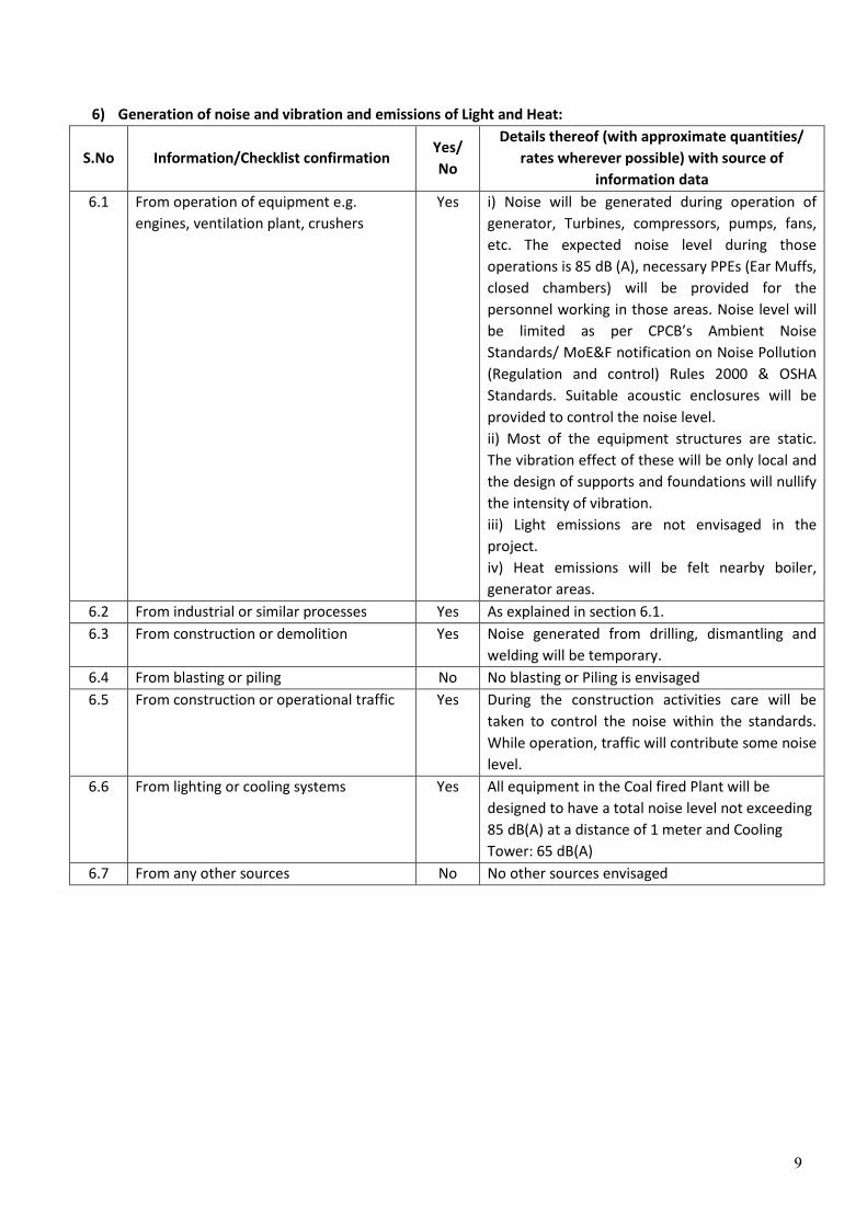
6) Generation of noise and vibration and emissions of Light and Heat:
S.No Information/Checklist confirmation Yes/
No
Details thereof (with approximate quantities/
rates wherever possible) with source of
information data
6.1 From operation of equipment e.g.
engines, ventilation plant, crushers
Yes i) Noise will be generated during operation of
generator, Turbines, compressors, pumps, fans,
etc. The expected noise level during those
operations is 85 dB (A), necessary PPEs (Ear Muffs,
closed chambers) will be provided for the
personnel working in those areas. Noise level will
be limited as per CPCB’s Ambient Noise
Standards/ MoE&F notification on Noise Pollution
(Regulation and control) Rules 2000 & OSHA
Standards. Suitable acoustic enclosures will be
provided to control the noise level.
ii) Most of the equipment structures are static.
The vibration effect of these will be only local and
the design of supports and foundations will nullify
the intensity of vibration.
iii) Light emissions are not envisaged in the
project.
iv) Heat emissions will be felt nearby boiler,
generator areas.
6.2 From industrial or similar processes Yes As explained in section 6.1.
6.3 From construction or demolition Yes Noise generated from drilling, dismantling and
welding will be temporary.
6.4 From blasting or piling No No blasting or Piling is envisaged
6.5 From construction or operational traffic Yes During the construction activities care will be
taken to control the noise within the standards.
While operation, traffic will contribute some noise
level.
6.6 From lighting or cooling systems Yes All equipment in the Coal fired Plant will be
designed to have a total noise level not exceeding
85 dB(A) at a distance of 1 meter and Cooling
Tower: 65 dB(A)
6.7 From any other sources No No other sources envisaged

10
7) Risks of contamination of land or water from release of pollutants into the ground or into sewers,
surface waters, ground water, coastal waters or the sea
S.No Information/Checklist confirmation Yes/
No
Details thereof (with approximate
quantities/ rates wherever possible) with
source of information data
7.1 From handling, storage, use or spillage
of hazardous materials
Yes Limited to dyke area
7.2 From discharge of sewage or other
effluents to water or the land (expected
mode and place of discharge)
Yes ETP and STP will be provided to collect waste
water from all the sources of plant area and
treated to re-use as far as possible.
7.3 By deposition of pollutants emitted to
air, into the land or into water
No The major emissions from the proposed
project are Particulate Matter (PM), SO2 and
NOx. Adequate control systems like ESP and
stack height meeting MoE&F guidelines will
be provided to control the emissions. Hence
there will not be any chance of
contamination of land and water by
deposition of pollutants emitted into air.
7.4 From any other sources No No other sources
7.5 Is there a risk of long term build up of
pollutants in the environment from these
sources?
Yes But within the prescribed limits by proper
Environmental Management Plan (EMP), Long
term risk of pollutants can be minimized.
8) Risk of accidents during construction or operation of the project, which could affect human health
or the environment
S.No Information/Checklist confirmation Yes/
No
Details thereof (with approximate
quantities/ rates wherever possible) with
source of information data
8.1 From explosions, spillages, fires etc., from
storage, handling, use or production of
hazardous substances
No Only minimum quantity of the chemicals
required will be stored within the plant
premises and safety precautions will be taken
while handling.
8.2 From any other sources No Adequate safety measures will be taken
8.3 Could the project be affected by natural
disasters causing environmental damage
(e.g. floods, earthquakes, landslides,
cloudburst etc.)?
No It is situated in earthquake zone-V as defined
in IS: 1893-2002.

11
9) Factors which should be considered (such as consequential development) which could lead
to environmental effects or the potential for cumulative impacts with other existing or
planned activities in the locality
S. No Information/
Checklist confirmation
Yes/
No
Details thereof (with approximate quantities/
rates wherever possible) with source of
information data
9.1 Lead to development of supporting facilities,
ancillary development or development
stimulated by the project which could have
impact on the environment e.g.
� Housing development
� Extractive industries
� Supply industries
� Others
No Ancillary building such as service building,
electrical switchgear room building etc., shall
be provided. These buildings shall generally be
constructed of RCC frame work within filled
brick work. Service building shall be separated
from Main TG building, atleast by 10 to 20 feet
with partition wall to avoid Noise. However,
the impact on environment if any will
be controlled by proper EMP.
9.2 Lead to after-use of the site, which could
have an impact on the environment
No Not Envisaged
9.3 Set a precedent for later developments Yes � Development of local community
� Improvement in Quality of life
� Ecological balance by sustainable
development
9.4 Have cumulative effects due to proximity to
other existing or planned projects with similar
effects.
Yes To avoid cumulative effects due to planned
projects with similar effects, at the time of
issue approvals, a minimum distance from one
unit to other unit will be maintained as per
MOEF siting guidelines.

12
(III) Environmental Sensitivity
S.No Areas Name/
Identity
Aerial distance (within 15 km.)
Proposed project location boundary
1 Areas protected under international
conventions, national or local legislation for
their ecological, landscape, cultural or other
related value
No None in the study area
2 Areas which are important or sensitive for
ecological reasons - Wetlands, watercourses or
other water bodies, coastal zone, biospheres,
mountains, forests.
Tipang RF
Tamdang RF
Tirap RF
Kotha RF
Uppar Dihing
RF
~6 km E
~9 km SSW
~12 km ENE
~9 km NE
~10 km NW
3 Areas used by protected, important or sensitive
species of flora or fauna for breeding, nesting,
foraging, resting, over wintering, migration
No There are no notified areas used by
sensitive species of flora & fauna in
the study area
4 Inland, coastal, marine or underground waters Buridihing
river
~6 km NW
5 State, National boundaries Arunachal
Pradesh State
~2.5 km S
6 Routes or facilities used by the public for access to
recreation or other tourist, pilgrim areas
No None in the study area
7 Defence installations No None in study area
8 Densely populated or built-up area Margherita
town
Parbatipur
Gaon
Ledo
~16km W
~6 km NE
~5km W
9 Areas occupied by sensitive man-made land
uses (hospitals, schools, places of worship,
community facilities)
Yes Most of the villages in the study area
have education & electricity facilities
but very few have health centers
10 Areas containing important, high quality or
scarce resources (ground water resources,
surface resources, forestry, agriculture, fisheries,
tourism, minerals)
No None in the study area
11 Areas already subjected to pollution or
environmental damage. (those where existing
legal environmental standards are exceeded)
No None
12 Areas susceptible to natural hazard which could
cause the project to present environmental
problems (earthquakes, subsidence, landslides,
erosion, flooding or extreme or adverse climatic
conditions)
No The project area is situated in
earthquake zone-V as defined in
IS: 1893-2002

13

14
Annexure -1
Plant Layout

15
Annexure 2
Topographical Map - 10km radius

16
Annexure 3
Google Earth Image

17
Annexure 4
Contour Map

18
Annexure 5
Process Description

19
Annexure 6
Water Balance Diagram

PRE FEASIBILITY REPORT FOR 1X 660 MW
SUPERCRITICAL MARGHERITA THERMAL PROJECT,
DISTRICT-TINSUKIA, ASSAM
ASSAM POWER GENERATION CORPORATION LIMITD Regd. Office: Bijulee Bhawan, 3
rd floor, Paltanbazar, Guwahati-781 001, Assam
Tele-Fax: 0361-2739546;

PRE FEASIBILITY REPORT FOR 1X 660 MW SUPERCRITICAL
MARGHERITA THERMAL PROJECT,
DISTRICT-TINSUKIA, ASSAM
ASSAM POWER GENERATION CORPORATION LIMITED
THIRD FLOOR,BIJULEE BHAWAN,PALTAN BAZAR,GUWAHARI-01,ASSAM
1
CONTENTS
Section Description
1 Project Highlights
2 Executive Summary
3 Introduction
4 Demand Analysis
5 Site Selection Study
6 Selection of Super Critical Technology
7 Technical Features of the Main Plant Equipments
8 Technical Features of Balance of Plants
9 Environmental Considerations
10 Execution and Project Management
11 Clean Development Mechanism (CDM)
12 Project Cost Estimate
13 Conclusion
14 Drawing list and drawings

PRE FEASIBILITY REPORT FOR 1X 660 MW SUPERCRITICAL
MARGHERITA THERMAL PROJECT,
DISTRICT-TINSUKIA, ASSAM
ASSAM POWER GENERATION CORPORATION LIMITED
THIRD FLOOR,BIJULEE BHAWAN,PALTAN BAZAR,GUWAHARI-01,ASSAM
2
SECTION – 1
PROJECT HIGHLIGHTS
1.0 Project Information & Location
1.1 Project Margherita Thermal Power Project
1.2 Plant capacity 1 x 660 MW
1.3 Promoter Assam Power Generation Corporation Limited(APGCL)
1.4 Plant site location Villages: Saliki NC,Lekhapani
Tehsil: Makum Mouza, Margherita Revanue Circle.
District: Tinsukia,State: Assam
1.5 Location co-ordinates 950 48’49. 4’’E Longitude
270 18’ 38.2’’ N Latitude
1.6 Nearest Town Margherita (~16 Km)
1.7 Major Town & City Tinsukia city (~55 Km)
1.8 State Capital Dispur, Guwahati (~550 Km)
1.9 Nearest Railway Station Ledo (~ 8), Lekhapani (~4 Km)
1.10 Nearest Airport Dibrugarh Airport (~100 Km)
2.0 Meteorically Condition
2.1 Climate Humid and tropical- A hot and humid pre- monsoon from
March to mid May, a prolonged southwest monsoon or
rainy season from mid May to September, a pleasant
post-monsoon or retreating monsoon from October to
November and a cold pleasant winter from December to
February
2.2
Site Elevation ~ varying from around 150 m to 236 m from eastern side
to western side above Mean Sea Level
2.3 Annual Maximum Mean
Temperature
31.4ºC

PRE FEASIBILITY REPORT FOR 1X 660 MW SUPERCRITICAL
MARGHERITA THERMAL PROJECT,
DISTRICT-TINSUKIA, ASSAM
ASSAM POWER GENERATION CORPORATION LIMITED
THIRD FLOOR,BIJULEE BHAWAN,PALTAN BAZAR,GUWAHARI-01,ASSAM
3
2.4 Annual Minimum Mean
Temperature
8.8 ºC
2.5 Design ambient temperature for
Continuous rating of Electrical
equipments.
50 ºC
2.6 Relative Humidity 88%
2.7 Average rain fall ~2600 mm
2.8 Basic design wind pressure As per IS: 875 (Latest Edition)
2.9 Seismic zone Zone-V
2.10 Maximum wind velocity 2.8 m/sec
3.0 Fuel Source and Consumption for 1 x 660 MW
3.1 Source of Fuel 100% indigenous Mergherita Coal from nearby North
Eastern Coalfields Ltd (NECL)
3.2 Grade G2 Grade (5500-6500 Kcal/kg)
3.3 Gross Calorific value 5500 Kcal/kg
3.4 Boiler fuel consumption 209 TPH
3.5 Boiler fuel consumption at 80%
PLF(Million tones/annum)
1.83
3.6 Coal storage days at site 15 days
3.7
Support Fuel & Source Heavy Furnace Oil (HFO)/Light Diesel Oil (LDO) from
nearest refinery at Digboi.
3.8 Support fuel required (HFO /LDO)
per annum
3725 KL
4.0 Ash Generation
4.1 Ash % in coal 6% to 15%
4.2 Ash generation in the boiler 32 TPH
5.0 Water Source and Quantity
5.1 Source of water The Make-up Water Requirement shall be met from
“Buridihing River” by Pumping water from approx. 14
Kms away from the Project site.
5.2 Raw water requirement 2100 m3/hr (Water drawal permission obtained for 3300
m3/hr)
6.0 Land requirement 575 Acres (Land allotted 661 acres)

PRE FEASIBILITY REPORT FOR 1X 660 MW SUPERCRITICAL
MARGHERITA THERMAL PROJECT,
DISTRICT-TINSUKIA, ASSAM
ASSAM POWER GENERATION CORPORATION LIMITED
THIRD FLOOR,BIJULEE BHAWAN,PALTAN BAZAR,GUWAHARI-01,ASSAM
4
7.0 Plant Equipment
7.1 Boiler Pulverized Coal firing Boiler (PC)
7.2 Boiler type Steam generator will be Once Through sliding
pressure supercritical boiler, Vertical wall evaporator with
rifle tubing, Conventional Two-pass, Radiant reheat,
Balanced draft and drumless type unit designed
for firing Indian coal as prime fuel
7.3 Steam Parameters per Boiler Flow – 2225 TPH ,Pressure – 256 ata , Temperature –
568± 5oC
7.4 Boiler efficiency 88%
7.5 Turbine Steam turbine will be a horizontally split, multi
cylinder (HP, Two IP, Two LP) 3000 rpm multistage,
Tandem compound, single reheat, condensing type unit
uncontrolled extractions for regenerative feed heating
with suitable to generate the 660000 KW at 21 KV,
Hydrogen cooled alternator
7.6 Turbine type Impulse cum reaction
7.7 Turbine speed 3000 RPM
7.8 Electrical Generator Two-pole, hydrogen-cooled turbo generator with
direct water cooling for the stator winding, which is
directly coupled to the turbines, a rotating-diode
brushless excitation system, 50 Hz., 3 phase, 0.85
power factor (lagging), 21 kV
7.9 Plant Heat Rate 2186 Kcal/KWh
7.10 Coal handling design capacity 1500 TPH for 14 hours operation with Two (2) Streams
(1W + 1S)
7.11 Bottom ash handling system Dense Phase Pneumatic System- semi wet extraction and
wet slurry disposal
7.12 Fly ash handling system Dense Phase Pneumatic System –Dry extraction with dry
disposal
7.13 Cooling tower type Induced Draft Cooling Tower
7.14 No. of Cooling tower One
7.15 Capacity 69000 m3/hr
7.16 Chimney One twin flue gas path

PRE FEASIBILITY REPORT FOR 1X 660 MW SUPERCRITICAL
MARGHERITA THERMAL PROJECT,
DISTRICT-TINSUKIA, ASSAM
ASSAM POWER GENERATION CORPORATION LIMITED
THIRD FLOOR,BIJULEE BHAWAN,PALTAN BAZAR,GUWAHARI-01,ASSAM
5
10. Annual Power Generation
10.1 Gross Generation at 100% PLF For 1 x 660 MW – 5781.6 million kWh
10.2 Gross Generation at 80% Plant PLF
For 1 x 660 MW – 4625.28 million kWh
10.3 Auxiliary Consumption for 660
MW @ 6% (per annum)
277.517 million kWh(80% PLF)
11.0 Costing
11.1 Total project cost Rs. 4383.98 crores
11.2 Interest during construction Rs. 763.54 crores
11.3 Total project Cost with IDC and
Contingency
Rs. 5278.20 crores
crores 11.4 Total Project cost per MW Rs. 8.00 crores
11.5 Cost of generation @ 85% PLF Rs.3.401 / Unit
on 1st year
11.6 Levellised cost of generation @ Rs. 3.220/ Unit
85% PLF
7.17 Height of chimney 275 Meter
7.18 Flue Gas Desulphurization Wet type
8.0 Project Schedule 48 Months
9.0 Man Power Requirement
9.1 During Construction Phase 175 personnel
9.2 During O & M 600 personnel

PRE FEASIBILITY REPORT FOR 1X 660 MW SUPERCRITICAL
MARGHERITA THERMAL PROJECT,
DISTRICT-TINSUKIA, ASSAM
ASSAM POWER GENERATION CORPORATION LIMITED
THIRD FLOOR,BIJULEE BHAWAN,PALTAN BAZAR,GUWAHARI-01,ASSAM
6
SECTION - 2
EXECUTIVE SUMMARY
2.1.0 Electricity is the prime mover of growth and is vital to the sustenance of a modern
economy. The growth of the Indian Economy depends heavily on the performance and
growth of the power sector as the Indian power sector contributes 10.17% in its Index
of Industrial Production (IIP) and has grown at a significant rate since independence.
Total generation capacity of the country, which was 1362 MW at the time of
independence, has increased to about 181500 MW in the last six decades. During the
year 2010 - 11, the country faced an energy shortage of 73,236 MU (8.5%) and a peak
shortage of 12,031 MW (9.8%). Therefore, it is endeavor of the government to ensure
that agriculture, industry, commercial establishments and households receive
uninterrupted supply of electricity at affordable rates. The total capacity addition
during the past 30 years between the 6th and the 11th Five Year Plans was
approximately 143,000 MW. A total capacity addition of 76,000 MW is planned for the
12th Five Year Plan (2012-17) which should result in substantial investments in the
power generation sector. The incremental increase of 41 GW is up to 31st March, 2011.
Further, demand for energy grows in tandem with the growth of the economy. It is
anticipated that annual growth rates of electrical energy consumption(utilities)
would be 12.19% at the end of 13th Plan compared to the growth rate of10.52% at the
end of 12th Plan (2012 - 2017).
In order to accelerate growth in the state, particularly in the industrial sector under the
open economic policy the state government is planning a number of initiatives including
investment subsidies, tax holiday etc. In the energy sector, major steps have been taken
to support the accelerated industrial growth and enhanced production in the
agricultural sector. The industrial development in the state till date has only been
nominal mainly due to lack of industrial infrastructure. Non availability of sufficient
electric power has been one of the greatest deterrents to the growth of industry and
agriculture in the State of Assam. Efforts are being made to promote industries in
mineral rich areas of the state as well as in the agro-based sector.
Assam possesses immense potential for development of the power sector. However,
despite being a storehouse of power, ranging from hydel to natural gas including oil and
coal resources, the progress of this sector in Assam has not taken place on a scale
commensurate with the possibilities. As a result, there exists a big gap between
availability and demand for power in the state. Assam accounted for only a small
fraction i.e. 0.16 per cent of the total generation of electricity in the country during
2000-2001
The proposed power plant consisting of following Major equipments and detailed
descriptions for equipments are described in section – 7 and section – 8

PRE FEASIBILITY REPORT FOR 1X 660 MW SUPERCRITICAL
MARGHERITA THERMAL PROJECT,
DISTRICT-TINSUKIA, ASSAM
ASSAM POWER GENERATION CORPORATION LIMITED
THIRD FLOOR,BIJULEE BHAWAN,PALTAN BAZAR,GUWAHARI-01,ASSAM
7
2.2.0 Steam Generating Unit
The steam generator will be sliding pressure supercritical, once-through type, utilizing a
Tangential Firing System for NOX control. Boiler is a single reheat, variable pressure
operation, with balanced draft furnace conditions. The unit is capable of firing the
range of pulverized coals as a Main fuel. The steam generating unit for 660 MW will
be sized for 2225 TPH steam flow at, 256 ata steam pressure and 568 ± 5 °C main
steam temperature, 595 ± 5°C reheat temperature with at 100% MCR Super heater
outlet with design consideration of indigenous coal. This will ensure adequate
margin over the requirement of Turbine at 100% MCR to cater for auxiliary steam. The
steam generator would be capable of maintaining main steam and hot reheat steam
temperatures of designed value between 60-100% MCR load or better. The steam
generator would be capable of operation with ‘the HP heaters out of service’ condition
and deliver steam to meet Turbo-generator requirement at 100% MCR. The steam
generators are coal fired with Heavy Fuel Oil firing (HFO) provision upto 30% Boiler
Maximum Continuous Rating (BMCR) for low load operation & flame stabilization
and Light Diesel Oil (LDO) firing provision to a maximum of 10% BMCR as secondary
fuel and start-up fuel respectively.
2.2.1 Boiler Feed Pumps and Drives
Four (4) nos. of Boiler feed pumps are envisaged for the unit. Two numbers (2 x 50%)
capacity Turbine Driven Feed Pumps (TD-BFP) shall be provided for each unit for
normal working along with 2 X 30% Motor Driven Feed Pumps (MD- BFP) as stand by
and start up purpose are envisaged.
2.2.2 Electrostatic Precipitator
The steam generating unit shall be installed with Six (6) Electrostatic Precipitators
comprising ten (10) bus sections in the direction of gas flow and two (2) bus sections
perpendicular to the gas flow.
2.2.3 Flue gas desulphurization unit:
Global environmental problems are drawing large attention in these days. Among these
SOx emission has become a major issue and consequently the importance of Flue Gas
Desulphuhzation (FGD) technology, as a counter- measure for this problem is becoming
greater. The Flue-gas desulphurization (FGD) or SO2 scrubbing processes typically uses
calcium or sodium based alkaline reagent. The reagent is injected in the flue gas in a
spray tower or directly into the duct. The SO2 is absorbed, neutralized and/or oxidized
by the alkaline reagent into a solid compound, either calcium or sodium sulphate. The
solid is removed from the waste gas stream using downstream equipment. Scrubbers are
classified as "once through" or "regenerable" based on how the solids generated by the
process are handled. Once through system either dispose of the spent sorbent as a

PRE FEASIBILITY REPORT FOR 1X 660 MW SUPERCRITICAL
MARGHERITA THERMAL PROJECT,
DISTRICT-TINSUKIA, ASSAM
ASSAM POWER GENERATION CORPORATION LIMITED
THIRD FLOOR,BIJULEE BHAWAN,PALTAN BAZAR,GUWAHARI-01,ASSAM
8
waste or utilize it as by-product. Regenerable systems recycle the sorbent back into the
system. Flue Gas from the boiler is induced Into the FGD plant by ID fans. Total gas
pressure loss in the FGD plant is compensated by ID fans. Bypass duct is provided to
permit isolation of FGD plant or flexible operation of boiler and FGD plant. A high sealing
efficiency damper is provided at the bypass duct of each FGD plant. A damper is provided
at the FGD Inlet duct. Similarly a damper is provided at the FGD outlet duct. Seal air fans
are installed for every damper
2.3.0 Steam Turbine Generator (STG)
The steam turbine of 660 MW, will be a horizontally split, multi cylinder (HP, Two IP
& Two LP) 3000 rpm multistage, tandem compound, single reheat, condensing type
unit uncontrolled extractions for regenerative feed water heating. The turbine will
be designed for main steam parameters of 247 ata, 565 0C at emergency stop valves of
H.P. turbine. The LP turbine will exhaust against condenser pressure of about 0.1 ata
(refer HMBD). The Turbo-generator set will be designed for a maximum throttle
steam flow at Turbine Valve Wide Open (V.W.O.) condition of about 105% of
Turbine MCR condition. The turbine will be rated for a minimum of 660 MW and shall
be capable of both constant variable pressure operations as well as with HP heater
out.
2.3.1 Condensing Equipment
One (1) no. of Double pass surface condenser, having different back pressures will be
provided per L.P Turbine with cooling water side of condensers in series with
adequate hot well capacity capable of maintaining the required vacuum while
condensing steam at the maximum rating of the turbine, will be provided. The
condenser is of box type construction with divided water box design and is provided
operation of one half of the condenser while the other half is under maintenance. The
steam space will be rectangular cross-section. The condenser is provided with integral
air cooling section from which air and non- condensable gases are drawn out with the
help of air evacuation equipment.
2.4.0 Generator
The Synchronous generators shall be totally enclosed, horizontal shaft driven directly by
steam turbine at 3000 rpm. The generator shall be cylindrical rotor, continuously rated
for the turbine outputs and rated at a minimum of 660MW, 0.85 (lagging power factor,
delivering power at 21 kV 3 phase, 50 Hz star connected, in IP-54 enclosure. The
generator will be provided with brushless excitation. The generators will be capable of
operating in isolation or in parallel with the power grid, with voltage variations of
±5% and frequency variations of 47.5 to 51.5 Hertz. No load short circuit ratio of the
generator at rated KVA and voltage will be about 0.49. The generator will have
Class-F insulation with temperature rise limited to class`B’ limits and shall be

PRE FEASIBILITY REPORT FOR 1X 660 MW SUPERCRITICAL
MARGHERITA THERMAL PROJECT,
DISTRICT-TINSUKIA, ASSAM
ASSAM POWER GENERATION CORPORATION LIMITED
THIRD FLOOR,BIJULEE BHAWAN,PALTAN BAZAR,GUWAHARI-01,ASSAM
9
hydrogen cooled. The inlet temperature of cooling water to the hydrogen coolers will be
33 degree C for design purpose.
2.5.0 Coal Handling System
2.5.1 Coal Requirement
The Coal requirement for the project will be 209 TPH which has been arrived based
on firing the 100% Indian Coal having GCV of 5500 kcal/kg & the plant heat rate 2186
kcal/kwh. The annual coal consumption shall be 1.83 Million Tons at 80% PLF.
Coal from the mine areas need to be transported to project site by railway wagons.
Broad gauge railway line from Ledo station upto the project site need to be investigated
and new lines from mines to the project site need to be installed for transportation of
coal. Railway line in Ledo station to coal fields may be augmented/modified as required
for transportation of coal. Inside the plant boundary, railway siding shall be provided
along with necessary Wagon Tippler arrangement for unloading of coal. The daily
requirement will result in to about one rake to two rake of coal comprising each rake
having 58 wagons with coal carrying capacity 58 Tons per wagons (i.e. 3364 Tons). Daily
coal requirement at full load is 5016 Tons and 15 days requirement of uncrushed coal
would be maintained in the plant.
2.6.0 Ash Handling System
The ash handling system is designed to meet the following parameters:
Table 2.1
Coal consumption at full load 209 TPH
Ash content in coal (worst) for design 15%
Total ash produced 32 TPH
Bottom Ash (25% - Design Condition) 8 TPH
Fly Ash (90% - Design Condition) 29 TPH
Dense Phase Pneumatic Ash handling system is envisaged with dry form for bottom ash.
Ash would be handled in dry condition, and the system would be equipped with
arrangement for dry disposal through Silos by truck. Since the sulphur content in
NEC/Margherita coal is very installation of de-sulphurisation process in the Power Plant
is become mandatory. For that wet type LSFO FGD technology is envisaged for this
project. Due to lower life cycle cost and capability of burning of high sulphur coal and
high SO2 removal with at least 95% efficiency of SO2 removal from the fly ash wet type
LSFO FGD technology is considered. The Flue-gas desulphurization (FGD) or SO2
scrubbing processes typically uses calcium or sodium based alkaline reagent required for

PRE FEASIBILITY REPORT FOR 1X 660 MW SUPERCRITICAL
MARGHERITA THERMAL PROJECT,
DISTRICT-TINSUKIA, ASSAM
ASSAM POWER GENERATION CORPORATION LIMITED
THIRD FLOOR,BIJULEE BHAWAN,PALTAN BAZAR,GUWAHARI-01,ASSAM
10
removal of sulphur be will be received from mines by road. The reagent is injected in the
flue gas in a spray tower or directly into the duct. The SO2 is absorbed, neutralized
and/or oxidized by the alkaline reagent into a solid compound, either calcium or sodium
sulphate. The solid is removed from the waste gas stream using downstream equipment.
2.7.0 Plant Water System
The Composite Water System shall be designed for economical utilization of water
for the power plant. The water consumption for the plant is estimated to 2100 M3/hr.
The make-up water shall be met from Buridihing River. The intake site is approximately
14 Km away from project site. For process use raw water will be clarified and filtered
and sent to DM plant. For potable and non critical process filtered water would be used
after sterilization.
Re-circulating cooling water system deploying semi-open recirculating cooling circuit
with wet type induced draft cooling tower would be used with clarified river water as
coolant.
Sweet water requirement for process and potable use would be met by filtered raw
water tank.
The DM water requirement for heat cycle make up would be met from the De-
mineralization plant.
2.8.0 Cooling Towers (CT)
One (01) no. of the induced draft type cooling tower shall be provided for the unit. The
cooling tower will discharge the recooled circulating water to CW pump house
circulating water sumps.
Number of cooling towers : One number
Type of cooling tower : Induced Draft.
Design inlet circulating water flow rate : 69,000 m3/hr
Cooling range of circulating water : 10 0C
Ambient wet-bulb temperature : 26.40 0C (for CT design)
Circulating water makeup : Clarified water

PRE FEASIBILITY REPORT FOR 1X 660 MW SUPERCRITICAL
MARGHERITA THERMAL PROJECT,
DISTRICT-TINSUKIA, ASSAM
ASSAM POWER GENERATION CORPORATION LIMITED
THIRD FLOOR,BIJULEE BHAWAN,PALTAN BAZAR,GUWAHARI-01,ASSAM
11
SECTION - 3
INTRODUCTION
3.1.0 Introduction
There has been substantial growth in demand of electric energy for domestic, industrial,
agricultural and commercial consumption in Assam in the past decade. In order to
sustain the intended development in agriculture & industry an increased demand for
electrical supply is foreseen.
The responsibility of generation of power in the state, at present, lies with the Assam
Power Generation Corporation Limited (APGCL) which came into existence after
disbanding of ASEB in Dec’ 2004 through State Power Sector Reform Program under the
provision of Electricity Act’ 2003. APGCL is a state owned Successor Company and inherited
the generating stations of ASEB. It is entrusted with the task of power generation in the
power starved state of Assam along with the daunting task of developing new power
projects with low allocation of natural resources required for power generation.
APGCL has at present installed capacity of 439.7 MW. APGCL is operating the following
power stations:
3.2.0 Projects under operation
Table 3.1
Sl.
No.
Name capacity
1 Namrup TPS (Gas based) 134 MW (effective 119.5 MW )
2. Lakwa TPS (Gas based) 157.2 MW
3. Karbi Langpi Hydro Power Station 100 MW
4 Myntriang small hydro project. Stage-II 2x1.5 MW
5 Chandrapur TPS (Oil based) 60 MW (under suspended Operation)
Now under revival process.
Total installed capacity 439.7 MW
APGCL has also taken up the following projects which are under stages of execution.

PRE FEASIBILITY REPORT FOR 1X 660 MW SUPERCRITICAL
MARGHERITA THERMAL PROJECT,
DISTRICT-TINSUKIA, ASSAM
ASSAM POWER GENERATION CORPORATION LIMITED
THIRD FLOOR,BIJULEE BHAWAN,PALTAN BAZAR,GUWAHARI-01,ASSAM
12
3.3.0 Projects under development
Table 3.2
Sl.
No.
Name Capacity (status)
1 Namrup Replacement plant 100 MW (Under construction)
2 Myntriang small hydro project. Stage-I 2X3 MW (Under construction)
3 Lakwa Replacement Power Plant 70 MW ( Procurement under process)
4 Lungnit small hydro project. 6 MW (Procurement under process)
5 Lower Kopili HEP 110 MW ( under scrutiny of
CEA)
6 Margherita Power plant 1X660 MW

PRE FEASIBILITY REPORT FOR 1X 660 MW SUPERCRITICAL
MARGHERITA THERMAL PROJECT,
DISTRICT-TINSUKIA, ASSAM
ASSAM POWER GENERATION CORPORATION LIMITED
THIRD FLOOR,BIJULEE BHAWAN,PALTAN BAZAR,GUWAHARI-01,ASSAM
13
SECTION – 4
DEMAND ANALYSIS
4.1.0 India has been facing electricity shortages in spite of appreciable growth in
electricity generation. The demand for electrical energy has been growing at the faster
rate and shall increase at higher growth rate to match with the projected growth of
Indian economy. The ‘per capita’ power consumption figure (209.21 kWh in 2009-10) for
the state of Assam stands well below the national average (778.63 kWh). The per capita
income (Rs. 33633) is also lower than national average (Rs.60,972) as per 2011-12
statistics released by GOI. In order to accelerate growth in the state, particularly in the
industrial sector under the open economic policy the state government is planning a
number of initiatives including investment subsidies, tax holiday etc. In the energy
sector, major steps have been taken to support the accelerated industrial growth and
enhanced production in the agricultural sector. The industrial development in the state
till date has only been nominal mainly due to lack of industrial infrastructure. Non
availability of sufficient electric power has been one of the greatest deterrents to the
growth of industry and agriculture in the State of Assam. Efforts are being made to
promote industries in mineral rich areas of the state as well as in the agro-based sector
It may be observed from the statistics of the state grid and the 17th Electric Power
Survey (EPS), published by the Ministry of Power, Government of India, that the energy
demand/supply position of the state of Assam at the end of the 12th Plan requires
substantial capacity addition particularly in thermal sector. The state grid depends
mainly on gas and hydel generation and partly on contribution from the Central Sector.
The above scenario highlights the need to add base load station to the state grid as a
measure to bridge the gap between the demand and supply. In order to induct more
base load thermal power stations for stability of the state grid, APGCL has proposed to
set up a 1X660 MW Thermal Power Station in Tinsukia district of Assam. The plant will
consist of Coal Fired PF Boiler Units, Steam Turbine Generator Units, Coal Handling Plant, Ash
Handling Plant, Flue Gas Desulphurisation Units and Balanced of Plant equipments and facilities.
The proposed power station at Margherita would use Assam coal as main fuel for the plant. The
coal will be sourced from the nearby mines of North Eastern Coal fields. Coal for the station shall
be made available from North Eastern Coal Fields which has adequate mineable high sulphur
coal reserve to feed the station for the designed life span of thirty (30) years.
The primary function of a power system is to supply its customers with electrical energy
as economically as possible with acceptable reliability and quality. Reliability is defined
as the ability of the system to satisfy the customer demand with acceptable quality. The
balance between the supply of electricity and the demand is quantified using a reliability
indicator called the Loss of Load Probability (LOLP). When this indicator is at an
appropriate level, called the “generation adequacy standard”, the supply/demand

PRE FEASIBILITY REPORT FOR 1X 660 MW SUPERCRITICAL
MARGHERITA THERMAL PROJECT,
DISTRICT-TINSUKIA, ASSAM
ASSAM POWER GENERATION CORPORATION LIMITED
THIRD FLOOR,BIJULEE BHAWAN,PALTAN BAZAR,GUWAHARI-01,ASSAM
14
balance is judged to be satisfactory. According to State grid codes, the accepted
generation adequacy standard is 2% (i.e. for 175 hours in a year the actual load is likely
to exceed the available generation). The draft National Electricity Plan (NEP)-2012,
stipulates that the accepted generation reliability standard shall be 0.2% (i.e. for 18
hours in a year the actual load may exceed the available generation leading to loss of
load events). The present LOLP of Assam is around 40% (meaning 40 % of the time in
year system load is exceeding available generation leading to load shedding) which is
unacceptable and will go up further if the uncertainty in import is also factored in.
One of the objectives of the National Electricity Policy is to ensure Per Capita availability
of electricity to be increased to over 1000 units by 2012.
To fulfill the above objective the state of Assam must have an aggressive program of
power generation capacity addition.
4.2.0 JUSTIFICATION OF THE POWER PROJECT
APGCL has not been able to enhance its generation capacity since commissioning of
2X50 MW Karbi Langpi Hydro Electric project in the year 2007. The 100 MW Namrup
project is a replacement project which will utilize the existing gas with an efficient
combined cycle plant. The 37.2MW Lakwa waste heat recovery project is being
retrofitted to the three 20 MW open cycle gas turbines.
The Assam Accord Amguri project has been put into cold storage to an indefinite period
due to non availability of gas. The four 15 MW units of Lakwa station has been proposed
to be replaced and the procurement process has started. All these plants are running on
available gas supply which was contracted decades ago.
Assam being rich in coal reserve, the main fuel for power generation has low per capita
power consumption. To bridge the present gap between demand and supply, any
capacity addition will be a welcome relief to this power starved state.
The major reasons which have encouraged APGCL to invest in Tinsukia district of Assam
are as follows:
• State of Assam has a meager per capita electricity consumption compared to
the national average. Accelerated growth in electricity consumption is expected
with opening of economy and exploitation of investment potential in the state.
Thus new capacity addition will be a welcome move.
• State of Assam has only a few coal based thermal power station till date.
• Adequate land may be available at a reasonable price near Margherita where
population density is low and quality of land is inferior from agricultural point of
view.

PRE FEASIBILITY REPORT FOR 1X 660 MW SUPERCRITICAL
MARGHERITA THERMAL PROJECT,
DISTRICT-TINSUKIA, ASSAM
ASSAM POWER GENERATION CORPORATION LIMITED
THIRD FLOOR,BIJULEE BHAWAN,PALTAN BAZAR,GUWAHARI-01,ASSAM
15
• Though land filling will be involved, the necessary soil can be arranged from the
reservoir and a terraced layout can be planned. For this proposed project no
human habitation, forest area or sanctuary would be encroached.
• The major benefit of this area is proximity to major coal fields.
• Transportation cost of coal from the mine to the proposed plant will be very
low.
• Consumptive water will be available from the Buri Dihing River and has low TDS
in this stretch.
• With infrastructure available in the region, substantial assistance can be availed.
• Road connectivity is already available at the moment and will involve
augmentation.
With the above in view, it is expected that the energy cost shall be reasonable and
market ability of power from the station will be attractive.
4.3.0 Benefits of the Project
Based on the plant model considered for the project, the following benefits may be
derived off:
• After the installation of plant Facilities continuous, uninterrupted power will be
supplied to the Grid.
• The implementation of the project would reduce overall expenditure to meet
the energy requirement and power deficit in the state.
• The costs per thermal energy made available from the solid fuels are
substantially low when compared with liquid fuels.
4.4.0 Government / Statutory Approvals
For setting up a Thermal power project a number of statutory and non-statutory
clearances are required. The salient clearances are listed below:

PRE FEASIBILITY REPORT FOR 1X 660 MW SUPERCRITICAL
MARGHERITA THERMAL PROJECT,
DISTRICT-TINSUKIA, ASSAM
ASSAM POWER GENERATION CORPORATION LIMITED
THIRD FLOOR,BIJULEE BHAWAN,PALTAN BAZAR,GUWAHARI-01,ASSAM
16
Table 4.1
S. No Particulars Approval Authority & Status
1. Land availability including
forest Land
Government of Assam, and Ministry of Environment
and Forest (MOEF).
Complete quantum of Land for installation of 1 X 660
MW is available. Total 661 acres of land has been
obtained from GoA for the project vide letter
no:RSS.1005/2012/19 dtd:06/04/2013
2. Water requirements and its
availability
Department: Water Resources Department, Assam.
The water requirement for the proposed 660 MW super
critical thermal power plant has been estimated
as 2100 m3 / hr.
The source of water is buridihing river. Water
allocation of 3300 M3 / hr was obtained from Water
resource Dept. GoA vide letter No.
3. Coal availability &
transportation
Requirement of Coal is estimated 209 Tons per day and
1.83 Million Tons Per Annum (MTPA).
The allocation of coal for the project is requested from
nearby coal Mines areas of North Eastern Coalfields
Ltd (NECL).
4. Pollution Control Clearance
(water and Air)
State Pollution control board (SPCB).
For such size of project, APCB in response for Public
Hearing.
5. Civil Aviation Clearance for
Chimney Height
National Airport Authority of India (AAI)
NOC yet to be taken from Airport Authority of India for
Construction of 275 M height chimney. Submission of
application is under process.
6. Rehabilitation & resettlement
plan
Ministry of Forest and Environment (MOEF) and
State Government. R&R Plan of APGCL has to be
approved by GoA.
7. Power absorption &
evacuation plan
State Electricity Board (SEB) / APDCL / other bulk
consumer(s).

PRE FEASIBILITY REPORT FOR 1X 660 MW SUPERCRITICAL
MARGHERITA THERMAL PROJECT,
DISTRICT-TINSUKIA, ASSAM
ASSAM POWER GENERATION CORPORATION LIMITED
THIRD FLOOR,BIJULEE BHAWAN,PALTAN BAZAR,GUWAHARI-01,ASSAM
17
8. Registration of company Registrar of company. Registered under Company
Act 1956 as wholly owned company of Govt. of Assam.
9. Environmental & Forest
Clearance from MoEF / State
Environment Dept.
Environmental Impact Assessment study and
Environmental Public hearing yet to be carried outs.
Environmental Clearance- Process for submission of
application is under process.
10. Local Panchayat Union /
Municipality approval
Local Authority
11. Electrical Approvals Inspector of Electrical department
12. Boiler Approvals Inspector of Boiler and Factories
13. Ash Utilization Plan Ash Utilization plan will be drawn as per MoEF
guidelines.
14. Approval by state regulatory
commission/Central Regulatory
Commission
As per Electricity Act 2003, approval of SERC for tariff
within the State and CERC for sale of electricity to more
than one state will be obtained at appropriate stage.

PRE FEASIBILITY REPORT FOR 1X 660 MW SUPERCRITICAL
MARGHERITA THERMAL PROJECT,
DISTRICT-TINSUKIA, ASSAM
ASSAM POWER GENERATION CORPORATION LIMITED
THIRD FLOOR,BIJULEE BHAWAN,PALTAN BAZAR,GUWAHARI-01,ASSAM
18
SECTION – 5
SITE SELECTION STUDY
5.1.0 Factors for Site Selection
The following main factors were considered when identifying a site for the Thermal
Power Plant.
• Availability of adequate vacant land in possession of APGCL free from R & R Issues.
• Availability of adequate water for cooling water & make up requirements.
• Non-forest, non-arable, compatible land use availability.
• Infrastructural facilities like road and for transportation.
• Proximity to nearby sub-stations for power evacuation.
• Adequate area for handling disposal / usage of ash
• Suitability of soil characteristics for construction.
5.2.0 Site Selection Concept
The selection of site is based on the following factors.
• Adequate un-inhabited, uncultivated non-forest land availability.
• General soil characteristics are suitable.
• Adequate land availability for ash disposal.
• The length of approach road to be constructed is minimum.
• Nearer to water source.
5.3.0 Details of Proposed Site and infrastructure
1 x 660 MW Margherita Thermal Power Project is proposed adjacent to the nearby coal
mines of North Eastern Coal Fields.
5.3.1 Approach to Proposed Site
The proposed 1 x 660 MW Margherita Thermal Power Project is located near Saliki
Village at a distance around 2 km south-west of NH38 in Margherita sub-divisional town
of Tinsukia District of Assam. Site is about 16 km from Margherita Town and about 60
km from Tinsukia. Nearest railway station is about 7 – 8 km at Ledo. The Latitude and
Longitude of the proposed land are 95048’49.4’’E & 27
018’38.2’’N. From NH-38 a kachha
road of approx. 3.5m width connects the site and the road extends further about 1.5kM
up to the abandoned Coal India Ltd.’s road bridge on Lekhapani river supposed to link
proposed Lekhapani Coal mines. However, there is dense forest beyond and there is no
forest department clearance for further construction. The land consists of hills and

PRE FEASIBILITY REPORT FOR 1X 660 MW SUPERCRITICAL
MARGHERITA THERMAL PROJECT,
DISTRICT-TINSUKIA, ASSAM
ASSAM POWER GENERATION CORPORATION LIMITED
THIRD FLOOR,BIJULEE BHAWAN,PALTAN BAZAR,GUWAHARI-01,ASSAM
19
valleys with areas covered with tea plantations. The entire site has hillocks having peaks
varying from 10 – 60 m. There are steep valleys between the hillocks. Southern side of
the land is flanked by hillock of approximate height of 100m. Elevation of the site varies
from 130 m to 256 m above MSL.
The proposed thermal power plant site can be accessed by road. It is located near Saliki
Village around 2 km south-west of NH38 in Margherita sub- divisional town of Tinsukia
about 16 km from Margherita Town and about 70 km from Tinsukia. From NH-38 a
kachha road of approx. Lekhapani River supposed to link proposed Lekhapani Coal
mines. This kachha road needs to be developed during project stage for heavy vehicle
movement. The site is connected with Dibrugarh Town by NH-37 via Tinsukia up to
Makum and NH-38 from Makum upto Lekkhapani. Further this highway merges into NH-
153 which goes upto Indian Border with Myanmar. The nearest railway station is at Ledo
at a distance of about 7 – 8Km connected by broad gauge line from Dibrugarh. Nearest
ports are at Kolkata and Haldia in West Bengal.
Land requirement:
Based on the CEA report “Review of land requirement for thermal power projects”
September, 2010; the land requirement analysis for 1X660 MW Margherita Super Critical
TPP is deliberated and as follows:
Sl No Description Land area in acres
1 Main plant 15
2 Coal handling system 80
3 Water system 18
4 Water reservoir 20
5 Switchyard 10
6 Miscellaneous BOP facilities, stores, roads 28
7 Total (Sl No1 to 5 above) 171
8 Green Belt (1/3 of Sl No 7.) 57
9 Ash disposal area 165
10 Township 100
11 Corridors for ash slurry, raw water and coal 82
12 Grand Total (Sl No 7 to 11 above) 575

PRE FEASIBILITY REPORT FOR 1X 660 MW SUPERCRITICAL
MARGHERITA THERMAL PROJECT,
DISTRICT-TINSUKIA, ASSAM
ASSAM POWER GENERATION CORPORATION LIMITED
THIRD FLOOR,BIJULEE BHAWAN,PALTAN BAZAR,GUWAHARI-01,ASSAM
20
5.3.2 Water requirement & availability
The total raw water requirement is estimated to be 2100 m3 / hr for the proposed 1 x
660 MW Power plant. Raw water sources for the proposed power plant will be made
from Buridihing river which is located 14 Kms (approx.) away from proposed site.
Semi- open circuit re-circulation type of cooling system using clarified water as make-up
with Induced draft cooling towers has been proposed for the cooling.
Fuel Availability & transportation
Indigenous cola will be considered as the main fuel for the Proposed 1 X 660 MW power
Plant. The coal will be sourced from the nearby mines of Eastern Coalfields Ltd (NECL)
near Margherita. There are numbers of mines operating in this coal field. These mines
have railway siding and coal from these mines are handled by railway wagon or
dumpers. The Coal requirement for the project will be 209 TPH which has been
arrived based on firing the 100% Indian Coal having GCV of 5500 kcal/kg & the plant
heat rate 2186 kcal/kwh. The annual coal consumption shall be 1.83 Million Tons at
80% PLF.
Coal from the mine areas need to be transported to project site by railway wagons.
Broad gauge railway line from Ledo station upto the project site need to be investigated
and new lines from mines to the project site need to be installed for transportation of
coal. Railway line in Ledo station to coal fields may be augmented/ modified as required
for transportation of coal.
Inside the plant boundary, railway siding shall be provided along with necessary Wagon
Tippler arrangement for unloading of coal.
The daily requirement will result in to about one rake to two rake of coal comprising
each rake having 58 wagons with coal carrying capacity 58 Tons per wagons (i.e.
3364Tons). Daily coal requirement at full load is 5016 Tons and 15 days requirement
of uncrushed coal would be maintained in the plant.
5.3.3 Auxiliary/Secondary Fuel
Auxiliary/Secondary Fuel viz. LDO & HFO would be required for startup & flame
stabilization at lower load. The required fuel oil has been estimated to be about 3725KL
per annum and will be sourced from nearest refinery at Digboi through road tankers.
5.3.4 Power Evacuation:
One number, double circuit 400kV transmission lines proposed for the from power
station switchyard up to Tinsukia EHV sub-station from the proposed generating power
plant. The distance of this sub-station from power house site is around 60 Km. One

PRE FEASIBILITY REPORT FOR 1X 660 MW SUPERCRITICAL
MARGHERITA THERMAL PROJECT,
DISTRICT-TINSUKIA, ASSAM
ASSAM POWER GENERATION CORPORATION LIMITED
THIRD FLOOR,BIJULEE BHAWAN,PALTAN BAZAR,GUWAHARI-01,ASSAM
21
400kV switchyard will be constructed in the proposed power plant for evacuation of
power.
5.3.5 Environmental Considerations
The site of the proposed power plant is highly undulated with ridges and valleys covered
with tea plantation & forest. Preliminary Geo-technical investigation for the proposed
project area is being carried out. There is no sanctuary, national park or archeological
monuments within 25 Km radius of the proposed site. River water will be used in semi-
open circuit for circulating water system. The proposed power station would be
equipped with modern, efficient pollution control devices to bring down the
emission/discharge of pollutants within the acceptable norms of the country
A study to assess the environmental impact of the proposed project will be conducted
and an Environmental Impact Assessment (EIA) report is to be prepared and furnished
to relevant agencies as per normal practice.

PRE FEASIBILITY REPORT FOR 1X 660 MW SUPERCRITICAL
MARGHERITA THERMAL PROJECT,
DISTRICT-TINSUKIA, ASSAM
ASSAM POWER GENERATION CORPORATION LIMITED
THIRD FLOOR,BIJULEE BHAWAN,PALTAN BAZAR,GUWAHARI-01,ASSAM
22
SECTION – 6
SELECTION OF S U PER CRITICAL TECHNOLOGY
6.1.0 Technology Selection
Higher capacity units came into operation in many countries at the end of last
century unit capacities have increased to 1300 MW. However in India, except for a
few units, the vast majority of the units were of 30 to 60 MW size till the seventies,
India have quite a few 500 MW units in successful operation from eighties onwards.
Still higher size unit like 660 MW units, are in the pipe line and are yet to be
commissioned. Now entrepreneurs have proposed to manufacture large unit size of 800
MW to 1000MW as the next size in the country with Super Critical Technology to
increase the pace of capacity addition.
The coal fired thermal power plants in India generally adopt sub critical
technology for generation of power. The overall thermal efficiency of a
conventional / sub-critical (operating steam pressure temp at 130 Kg/sq.cm,5400C)
coal fired thermal power plants depends on the combustion technology, operating
conditions and coal properties.
Sub Critical Boilers (500 MW sets) involves steam pressure of 170 bar and super heat /
reheat temperature 5400C/540
0C and super critical boilers would be designed
with pressure of 257 ata and super heat/reheat temperature of 5680C /592
0C. Main
focus about super critical boiler is on minimizing CO2 emission originating from the
fossil fired plants. CO2 increase is linked to Global warming. Hence it offers advantage
of “Burn less fuel for the same output” thus economical use of energy resources and low
emission.
Above an operating pressure of 225 Kg/sq.cm (temp.560 deg. C), the cycle is
supercritical wherein the medium is a single phase fluid with homogeneous
properties and there is no need to separate steam from water in a drum. Once
through boilers are therefore been used in supercritical cycles. Adoption of once
through boiler technology has advantage of operational flexibility to respond quickly
to load changes and grid fluctuations, siding pressure operation and shorter start-
up times.
The proposed project employs supercritical coal fired power generation unit having 660
MW gross capacity. Supercritical technology, which is first-of-its kind in India,
enables Rankine cycle to be operated at higher operating pressures thereby
increasing the cycle efficiency. Higher efficiency means a reduction in fuel
consumption and thereby a reduction in emissions per unit of electricity generated.
The supercritical technology will enhance operational efficiency over sub-critical
technology, which is the most prevalent and commonly used for thermal power
generation in India.

PRE FEASIBILITY REPORT FOR 1X 660 MW SUPERCRITICAL
MARGHERITA THERMAL PROJECT,
DISTRICT-TINSUKIA, ASSAM
ASSAM POWER GENERATION CORPORATION LIMITED
THIRD FLOOR,BIJULEE BHAWAN,PALTAN BAZAR,GUWAHARI-01,ASSAM
23
Hence adopting super critical technology for higher size of coal based units leads to
enhanced plant efficiency, less fuel consumption and reduced green house
emissions.
Adopting supercritical technology has the following advantages:
• Superior technology
• Reduced green house emissions
• Environmental friendly / CDM benefits
• Operational flexibility to grid fluctuations
• Shorter start-up times
• Reduced coal consumption
• Savings in coal cost
• Reduced O&M cost
• Improved ash management

PRE FEASIBILITY REPORT FOR 1X 660 MW SUPERCRITICAL
MARGHERITA THERMAL PROJECT,
DISTRICT-TINSUKIA, ASSAM
ASSAM POWER GENERATION CORPORATION LIMITED
THIRD FLOOR,BIJULEE BHAWAN,PALTAN BAZAR,GUWAHARI-01,ASSAM
24
SECTION – 7
TECHNICAL FEATURES OF T H E MAIN PLANT EQUIPMENTS
7.1.0 Steam Generating Units
The steam generator will be sliding pressure supercritical, once-through type, utilizing a
Tangential Firing System for NOX control. Boiler is a single reheat, variable pressure
operation, with balanced draft furnace conditions. The unit is capable of firing the range
of pulverized coals as a Main fuel.
The steam generating unit for 660 MW will be sized for 2225 TPH steam flow at, 256
ata steam pressure and 568 °C main steam temperature, 593 °C reheat temperature
with at 100% MCR Super heater outlet with design consideration of 100 %
indigenous coal as prime fuel. This will ensure adequate margin over the requirement
of Turbine at 100% MCR to cater for auxiliary steam.
The steam generator would be capable of maintaining main steam and hot reheat steam
temperatures of designed value between 60-100% MCR load or better. The steam
generator would be capable of operation with ‘the HP heaters out of condition’ and
deliver steam to meet the turbo-generator requirement at 100% MCR.
The steam generators are coal fired with Heavy Fuel Oil firing (HFO) provision upto
30% Boiler Maximum Continuous Rating (BMCR) for low load operation & flame
stabilization and Light Diesel Oil (LDO) firing provision to a maximum of 10% BMCR
as secondary fuel and start-up fuel respectively.
7.1.1 Salient Features of the Proposed Boiler
• Once through sliding pressure supercritical boiler
• Vertical wall evaporator with rifle tubing.
• Conventional Two-pass
• Radiant reheat
• Balanced draft
• Low load start-up system up to 30%BMCR load.
• Tilting Tangential burners
• Side mill layout, cold PA system
• Two (2) axial reaction FD fans

PRE FEASIBILITY REPORT FOR 1X 660 MW SUPERCRITICAL
MARGHERITA THERMAL PROJECT,
DISTRICT-TINSUKIA, ASSAM
ASSAM POWER GENERATION CORPORATION LIMITED
THIRD FLOOR,BIJULEE BHAWAN,PALTAN BAZAR,GUWAHARI-01,ASSAM
25
• Two (2) axial reaction PA fans
• Two (2) axial reaction ID fans
• Two (2) regenerative Tri-sector air heaters
• Nine (9) vertical spindle bowl mills
• Nine (9) gravimetric feeders (Microprocessor Based)
• ESP with 25 mg/Nm3 outlet dust emission (with one field out condition)
• Micro-processor based BMS, SADC and SB controls.
7.1.2 Furnace
The boiler is a two-pass design of gas-tight welded-wall design. The boiler is of dry
bottom type with vertical tubes enclosing the furnace from the coutant bottom to
evaporator outlet.
7.1.3 Economiser
Economisers help to improve boiler efficiency by extracting heat from flue gases
discharged from the final reheater section of a radiant-reheat unit. Heat is transferred
to the feed water, which enters at a temperature appreciably lower than that of
saturated steam. Economizers are arranged for downward flow of gas and upward flow
of water.
Designing the economiser for counter flow of gas and water results in maximum log
mean-temperature difference for heat transfer. Upward flow of water helps avoid water
hammer, which may occur under the some operating conditions. The proposed
economizer is an in-line, bare tube arrangement.
7.1.4 Superheater and Reheater
The superheater and reheater design depends on the specific duty to be
performed. For relatively low final outlet temperatures, superheaters solely of the
convection-type are generally used. For higher final temperatures, surface requirements
are larger and of necessity, superheater elements are located in high gas-temperature
zones. Wide-spaced platen superheaters or reheaters of the radiant type are then used
as a standard boiler designs.
7.1.5 Boiler Pressure Parts
The boiler has convection heat transfer areas located inside a box formed by welded
membrane walls. In these, wall openings are provided for wind boxes, flue gas outlet,
access, inspection doors, and soot blowers.

PRE FEASIBILITY REPORT FOR 1X 660 MW SUPERCRITICAL
MARGHERITA THERMAL PROJECT,
DISTRICT-TINSUKIA, ASSAM
ASSAM POWER GENERATION CORPORATION LIMITED
THIRD FLOOR,BIJULEE BHAWAN,PALTAN BAZAR,GUWAHARI-01,ASSAM
26
The boiler and its auxiliary equipment are designed and arranged in such a
manner that all parts can be inspected with minimal effort. All important parts are
accessible by platforms.
7.1.6 Firing System
Tangentially fired steam generators inject the fuel and air streams from wind boxes in
the furnace corners, tangent to an imaginary circle in the center of the furnace. A single
rotating flame envelope (commonly referred to as a fireball) is created. The
impingement of laterally adjacent streams promotes bulk mixing for complete
combustion. Since fuel/air mixing and corner ignition stability occur by global vortex
rather than local swirl mechanics, the phrase “the furnace is the burner” is uniquely
applied to tangentially fired units.
Tangentially fired boilers have demonstrated low NOx production. The long
diffusion flames emanating from each corner, plus the large amount of internal gas
recirculation generated by the cyclonic fireball, moderate fuel and air mixing. This
forms the basis of an inherently low NOx system. In contrast, wall-fired boilers utilize
groups of individually self-stabilizing burners that do not use global furnace flow
patterns to achieve uniform fuel and air mixing. As a result, wall- fired arrangements,
even that employing separate over fire air, typically create local zones of high
temperature and oxygen concentration that lead to high NOx formation.
7.1.7 Pulverisers
The pulverizing system is a highly efficient, reliable and flexible system for
meeting a wide range of solid fuel preparation needs.
Bowl mill type pulverizer has been continually refined to meet the ever-changing service
conditions. Low power consumption, low maintenance costs, wide capacity range
and high availability. Nine (09) numbers of pulverizers are envisaged.
7.1.8 Boiler Feed Pumps and Drives
Four (4) nos. of Boiler feed pumps are envisaged for the unit. Two numbers (2 x 50%)
capacity turbine driven feed pumps shall be provided for the unit for normal
working along with 2 X 30% Motor Driven Feed Pumps as stand by and start up
purpose are envisaged.
The MD-BFP shall be driven by constant speed squirrel cage induction motor with
hydraulic coupling between motor and main pump and booster pump at other end of
motor. TD-BFP shall be driven by variable speed turbine drive with suitable
coupling between turbine and main pump and booster pump at other end of turbine
with a gear box for each TD-BFP.

PRE FEASIBILITY REPORT FOR 1X 660 MW SUPERCRITICAL
MARGHERITA THERMAL PROJECT,
DISTRICT-TINSUKIA, ASSAM
ASSAM POWER GENERATION CORPORATION LIMITED
THIRD FLOOR,BIJULEE BHAWAN,PALTAN BAZAR,GUWAHARI-01,ASSAM
27
Main pump shall be horizontal, centrifugal type, multistage, outer casing barrel type
with end rotor removal. Booster pump shall be single stage, two bearing design and
double suction impeller type.
7.1.9 Electrostatic Precipitator
Steam generating unit shall be installed with Six (6) Electrostatic Precipitators
comprising ten (10) bus sections in the direction of gas flow and two (2) bus sections
perpendicular to the gas flow.
The ESP would have a collection efficiency of around 99.89%. The outlet dust
concentration from the chimney will be limited to 25 mg/Nm3 as per the latest
regulation of Central Pollution Control Board. ESP will be provided with One Hundred
and Twenty (120) ash hoppers having capacity suitable for storing ash collected in at
least one (1) shift operation of the Boiler at 100% MCR.
7.1.10 Brief Technical Specification of Boiler and Auxiliaries
All the below values are typical applicable for the unit only.
Table 7.1
Sl. No Description Units Values
A Boiler
1. Type of Boiler - Pulverized Coal Fired
Main Steam
2. Superheater outlet steam flow T/hr 2225
3. Steam pressure at SH outlet ata 256
4. Steam temperature at SH outlet Deg.C 568
Reheat Steam
5. Reheat steam flow T/hr 1609.97
6. Steam pressure at RH Inlet ata 55.92
7. Steam pressure at RH outlet ata 50.33
8. Steam temperature at RH inlet Deg. C 337.8

PRE FEASIBILITY REPORT FOR 1X 660 MW SUPERCRITICAL
MARGHERITA THERMAL PROJECT,
DISTRICT-TINSUKIA, ASSAM
ASSAM POWER GENERATION CORPORATION LIMITED
THIRD FLOOR,BIJULEE BHAWAN,PALTAN BAZAR,GUWAHARI-01,ASSAM
28
9. Steam temperature at RH Outlet Deg. C 593.0
10. Feed water temperature at economizer
inlet
Deg.C 290.0
11. Flue gas outlet temperature Deg.C 145
12. Excess air(at 100% MCR) % 20
13. Superheat temp control - By spray
14. RH temp control By burner tilt + Spray +excess air
adjustment 15. Safety Valves - As per system requirement on SH,
RH etc. 16. Soot blowers - As per manufacturers design
17. Regenerative Airpreheater - Motor driven
18. Ambient air temperature Deg.C 32
19. Maximum temperature entering close
spaced platens
Deg.C as per design requirement
B Electrostatic Precipitator
1. Number of precipitators per boiler Nos. Six (06)
2. Number of gas paths per precipitator Nos. Two (02)
3. Number of electrical fields (Zones) in
series in the direction of the gas flow
Nos. Ten (10)
4. Total number of electrical fields per
boiler
Nos. 120
5. Space between the centers of collecting
electrodes across the gas path
m
400
6. Outlet dust concentration with one
field out of service
mg/Nm3
max)
25
7. Maximum flue gas velocity through
ESP
m/s 1
8. Minimum treatment time of flue gas sec 20
9. Minimum aspect ratio m 1.5
10. Specific collecting area m2 180
C. Boiler Feed Pump

PRE FEASIBILITY REPORT FOR 1X 660 MW SUPERCRITICAL
MARGHERITA THERMAL PROJECT,
DISTRICT-TINSUKIA, ASSAM
ASSAM POWER GENERATION CORPORATION LIMITED
THIRD FLOOR,BIJULEE BHAWAN,PALTAN BAZAR,GUWAHARI-01,ASSAM
29
1. Number of BFP sets per STG unit Nos. 2 x 50% Turbo driven & 2 x 30%
Motor driven 2. Liquid Handled - Boiler feed water
3. Rated capacity m3 / hr 1600
4. Feed water temperature at pump
inlet
º C 187.5
5. Type of Coupling - variable speed Fluid Coupling
7.2.0 Steam Turbine Generator ( STG )
The steam turbine of 660 MW, will be a horizontally split, multi cylinder (one HP,
Two IP, Two LP) 3000 rpm multistage, tandem compound, single reheat, condensing
type unit uncontrolled extractions for regenerative feed water heating. The turbine will
be designed for main steam parameters of 247 ata, 5650C at emergency stop valves of
H.P. turbine.
The LP turbine will exhaust against condenser pressure of about 0.10 ata (refer HMBD).
The Turbo-generator set will be designed for a maximum throttle steam flow at
Turbine Valve Wide Open (V.W.O.) condition of about 105% of Turbine MCR
condition. The turbine will be rated for a minimum of 660 MW and shall be capable
of both constant variable pressure operations as well as with HP heater out.
The turbine auxiliaries shall comprise of the following:
- Automatic turbine test gear
- Low vacuum unloading gear
- Turbine governing system
- Initial pressure regulator
- Control fluid system
- Turning gear and oil pumps (ac/dc motor driven)
- Turbine oil system with centrifuge & vapour extractor, for bearings, generator
seals, jacking, turning gear etc.
- AC/DC motor-operated Jacking oil pumps
- Lube Oil purification system
- Oil Cooler
- Automatic Turbine Run-up System (ATRS)

PRE FEASIBILITY REPORT FOR 1X 660 MW SUPERCRITICAL
MARGHERITA THERMAL PROJECT,
DISTRICT-TINSUKIA, ASSAM
ASSAM POWER GENERATION CORPORATION LIMITED
THIRD FLOOR,BIJULEE BHAWAN,PALTAN BAZAR,GUWAHARI-01,ASSAM
30
- Stress Evaluator
A fully automatic gland sealing system is provided and the turbo-generator is equipped
with the following:
a) Electro-hydraulic governing system backed up by Hydro-mechanical system ensuring
stable operation under grid fluctuation
b) Hydraulic oil driven rotor turning gear
c) Self contained lubricating oil system for supplying oil to Turbine and
Generator bearings to the governing and control system and also to
Generator Seal Oil System.
7.2.1 Condensing Equipment
One (1) no. of double pass surface condenser, having different back pressures will be
provided per LP Turbine with cooling water side of condensers in series with
adequate hot well capacity capable of maintaining the required vacuum while
condensing steam at the maximum rating of the turbine, will be provided for the unit.
The condenser is of box type construction with divided water box design and is provided
operation of one half of the condenser while the other half is under maintenance. The
steam space will be rectangular cross-section. The condenser is provided with integral
air cooling section from which air and non- condensable gases are drawn out with the
help of air evacuation equipment.
7.2.2 Feed Cycle Equipment
Three (03) high pressure (HP) horizontal / vertical heaters and U-tube type are provided
with both drain cooling and desuperheating zones in addition to the normal condensing
zone. HP heaters are provided with individual bypasses to allow isolation and
maintenance. ASME-TWDPS-I recommendations for preventing water damage to
turbine shall be followed.
Four (04) low pressure (LP) horizontal / vertical feed water heaters are envisaged.
The LP heaters are designed to mountain in the condenser neck. The drain cooler shall
be installed outside the condenser neck. Extraction pipes routed through condenser
neck shall be provided with stainless steel shroud to prevent erosion due to steam. LP
heater 2, 3 and 4 can be individually isolated and by- passed.
The unit is provided with a variable pressure Spray- cum-Tray -cum-Reboiling type
deaerating heater with a feed water storage tank of adequate capacity. Deaerator is
designed to deaerate all the incoming condensate and drain flow to keep the oxygen
content of the condensate below the permissible limit of 0.005 cc / litre.
7.2.3 Brief Technical Specification of Steam Turbine and Major Feed Cycle Equipments

PRE FEASIBILITY REPORT FOR 1X 660 MW SUPERCRITICAL
MARGHERITA THERMAL PROJECT,
DISTRICT-TINSUKIA, ASSAM
ASSAM POWER GENERATION CORPORATION LIMITED
THIRD FLOOR,BIJULEE BHAWAN,PALTAN BAZAR,GUWAHARI-01,ASSAM
31
Table 7.2
S. No Description Units Values
A Turbine
1. Type - Tandem Compound
2. Number of cylinders - Multi Cylinder
3. Type of governing - Digital electro hydraulic
4. Speed RPM 3000
5. Maximum continuous rating per unit KW 660000
6. Mail Steam at HP Turbine emergency stop
valve
a Pressure ata 247
b Temperature Deg.C 565
7. Hot reheat steam at IP Turbine terminal
point
a Pressure loss from HP Turbine outlet
terminal point to LP Turbine inlet terminal
ata 5.57
b Temperature Deg.C 593
8. Condenser Pressure ata 0.104
9. Final feed water temperature Deg.C 290
10 Turbine speed min -1 3000
11. SH steam flow required for with 0%
T/hr 1915.21
12. Circulating water to condenser per unit (@
m3/hr 65000
13. Maximum temp. rise of circulating water Deg C 9
14. Turbine Heat Rate Kcal/Kwh 1850
B. Condenser Cooling water Pumps
1.
Number of pumps required - 5 (4 W +1 S)

PRE FEASIBILITY REPORT FOR 1X 660 MW SUPERCRITICAL
MARGHERITA THERMAL PROJECT,
DISTRICT-TINSUKIA, ASSAM
ASSAM POWER GENERATION CORPORATION LIMITED
THIRD FLOOR,BIJULEE BHAWAN,PALTAN BAZAR,GUWAHARI-01,ASSAM
32
2.
Rated capacity m3/hr 17000
3.
Water inlet temp Deg C 33 0C (max) for condenser
design.
4.
Number of stages - Two (02)
5.
Location - Indoor
7.2.4 Generator
The Synchronous generators shall be totally enclosed, horizontal shaft driven
directly by steam turbine at 3000rpm. The generator shall be cylindrical rotor,
continuously rated for the turbine outputs and rated at a minimum of 660MW, 0.85
(lagging power factor, delivering power at 21kV 3 phase, 50 Hz star connected, in IP-
54 enclosure. The generator will be provided with brushless excitation. The
generators will be capable of operating in isolation or in parallel with the power grid,
with voltage variations of ±5% and frequency variations of 47.5 to 51.5 Hertz. No load
short circuit ratio of the generator at rated KVA and voltage will be about 0.49. The
generator will have Class-F insulation with temperature rise limited to class`B’ limits
and shall be hydrogen cooled. The inlet temperature of cooling water to the hydrogen
coolers will be 33 degree C for design purpose.
All six terminals of generator windings will be brought out and three shorted in the
neutral formation terminal box and grounded through secondary resistance loaded
distribution transformer to restrict earth fault current and to reduce transient over
voltage.
The generator will have overload capacity as per IEC 60034-3 and 150 percent of rated
current for 30 sec after attaining thermal equilibrium at rated load and voltage. The
generator will withstand an over speed of 20% for 2 min.
The excitation system will be capable of supplying excitation current of the
generator under all conditions of operation of load voltage and power factor. Rated
current and voltage of the exciter will be at least 120% of normal excitation
current and at least 110% of no load excitation voltage with minimum of 150%
ceiling. Each generator will be provided with the following:
a) Automatic high speed digital, dual channel AVR, capable of maintaining steady-
state terminal voltage within +0.5% of the preset value under all operating
conditions and capable of smooth and continuous running over the operating
band width.
b) Excitation control cubicle.

PRE FEASIBILITY REPORT FOR 1X 660 MW SUPERCRITICAL
MARGHERITA THERMAL PROJECT,
DISTRICT-TINSUKIA, ASSAM
ASSAM POWER GENERATION CORPORATION LIMITED
THIRD FLOOR,BIJULEE BHAWAN,PALTAN BAZAR,GUWAHARI-01,ASSAM
33
c) Surge protection equipment.
d) Neutral grounding equipment.
e) Current and potential transformers.
f) Generator control metering and protection panel.
g) Hydrogen cooling system.
h) Jacking oil, bearing oil and seal oil systems covered under turbine.
Table 7.3
S. No Description Values / unit
1. Rated KW capacity at TMCR 660000 KW
2. Rated KVA capacity 776470.58 KVA
3. Rated terminal voltage 21 KV
4. Rated power factor 0.85 lagging
5. Rated stator current 21347.404 Amp
6. Rated speed 3,000 RPM
7. Rated frequency 50 Hz
8. Efficiency at rated power output @ 0.85 p.f 98.82% (approx.)
9. Short circuit ratio Rated hydrogen pressure
(gauge) 3.5 kg/cm2
0.5 ± 15%

PRE FEASIBILITY REPORT FOR 1X 660 MW SUPERCRITICAL
MARGHERITA THERMAL PROJECT,
DISTRICT-TINSUKIA, ASSAM
ASSAM POWER GENERATION CORPORATION LIMITED
THIRD FLOOR,BIJULEE BHAWAN,PALTAN BAZAR,GUWAHARI-01,ASSAM
34
SECTION – 8
TECHNICAL FEATURES OF B A L A NC E OF P L A NT S
8.1.0 Mechanical Systems
Balance of plant includes coal handling plant, Fuel oil unloading storage and
handling, Mill rejects systems, ash handling plant, plant water systems, cooling towers,
Raw water treatment plant, CW chlorination, RW chlorination system, CW pumps,
Condensate polishing unit, Effluent treatment plant, Air conditioning & ventilation
system, Fire protection system, Hydrogen generation plant, Compressed air
system, Elevators, Miscellaneous cranes & Hoists, Workshop equipments, chemical
laboratory etc shall be designed to meet the plant requirements.
8.1.1 Coal Handling System
8.1.1.1 Coal availability and Requirement
Indigenous coal will be considered as the main fuel for the Proposed 1 X 660 MW power
Plant. The coal will be sourced from the nearby mines of North Eastern Coalfields Ltd
(NECL) near Margherita. There are numbers of mines operating in this coal field. These
mines have railway siding and coal from these mines are handled by railway wagon or
dumpers. The Coal requirement for the project will be 209 TPH which has been
arrived based on firing the 100% indigenous Coal having GCV of 5500 kcal/kg & the
plant heat rate 2186 kcal/kwh. The annual coal consumption shall be 1.83 Million Tons
at 80% PLF.
8.1.1.2 Coal Transportation
Coal from the mine areas need to be transported to project site by railway wagons.
Broad gauge railway line from Ledo station upto the project site need to be investigated
and new lines from mines to the project site need to be installed for transportation of
coal. Railway line in Ledo station to coal fields may be augmented/ modified as required
for transportation of coal.
Inside the plant boundary, railway siding shall be provided along with necessary Wagon
Tippler arrangement for unloading of coal Railway consultant.
The daily requirement will result in to about one rake to two rake of coal comprising
each rake having 58 wagons with coal carrying capacity 58 Tons per wagons (i.e.
3364Tons). Daily coal requirement at full load is 5016 Tons and 15 days requirement
of uncrushed coal would be maintained in the plant.2X1500 TPH crushing and
conveying system with 14 hrs operation is envisaged.
8.1.1.3 Proposed System Description

PRE FEASIBILITY REPORT FOR 1X 660 MW SUPERCRITICAL
MARGHERITA THERMAL PROJECT,
DISTRICT-TINSUKIA, ASSAM
ASSAM POWER GENERATION CORPORATION LIMITED
THIRD FLOOR,BIJULEE BHAWAN,PALTAN BAZAR,GUWAHARI-01,ASSAM
35
Crushing System
Unloaded coal is conveyed to crusher house by belt conveyors via pent house and
transfer points. Suspended magnets are provided on conveyors at pent house for
removal of tramp Iron pieces. Metal detectors are also provided to detect non-ferrous
materials present in the coal before crushers.
One number crusher house will be envisages for the proposed power plant, having 4
nos. of crushers (2W + 2S), arrangement with primary and secondary crushers with
reversible belt feeders, flap gates & screens etc.
Crushers crush the coal up to (–) 25 mm size through primary and secondary crushers
and after crushing convey to outgoing conveyors in the coal path through flap
gates and reversible belt feeders.
Coal Conveying from Crusher House to Boiler Bunkers
Coal from crusher house will be conveyed to boiler bunkers through a series of
conveyors with necessary flap gates, fixed trippers, motorized Traveling trippers.
Inline Magnetic Separators, metal detectors, Electronic belt scales shall be
provided at appropriate places, Automatic type Coal Sampling unit, Dust
suppression, Dust extraction and Ventilation system will be considered.
8.1.2 Ash Handling System
The ash handling system is designed to meet the following parameters:
Table 8.1
Coal consumption at full load 209 TPH
Ash content in coal (worst) for design 15%
Total ash produced 32 TPH
Bottom Ash (25% - Design Condition) 8 TPH
Fly Ash (90% - Design Condition) 29 TPH
The system envisages the following:-
a) Intermittent semi-dry extraction of Bottom ash
b) Dry fly ash collection in silos of 16 hours aggregate storage capacity and passing
through FGD.
8.1.2.1 Bottom Ash System

PRE FEASIBILITY REPORT FOR 1X 660 MW SUPERCRITICAL
MARGHERITA THERMAL PROJECT,
DISTRICT-TINSUKIA, ASSAM
ASSAM POWER GENERATION CORPORATION LIMITED
THIRD FLOOR,BIJULEE BHAWAN,PALTAN BAZAR,GUWAHARI-01,ASSAM
36
The scheme proposes semi-dry extraction and disposal of economiser and bottom for
the first three year of operation of the plant. Ash utilisation of 50% in 1st year, 70% in
2nd year and 90% in 3rd year has been considered. Bottom ash from the furnace would
be collected in a water-impounded hopper provided with feed gates, feed hoppers and
clinker grinders. The bottom ash clinkers will be ground in clinker grinders and will be
transported by jet pumps to ash slurry sump (for bottom ash) from where bottom ash
slurry will be pumped to ash dump outside the plant boundary. The design capacity of
bottom ash conveying system considered should be adequate to clean bottom ash
collected in a shift of eight (8) hours within two (2) hours. There will be continuous
make-up water to be supplied to Bottom Ash Hopper. The over flow water from BA
Hopper and seal trough will be clarified and will be reused in the Ash Water System.
Bottom Ash Slurry will be pumped to permanent Ash Pond. 100% Ash Water recovery
system would be provided to recover and reuse the Ash Pond Water. The H.P. & L.P
water pumps to be located in a common ash water sump in ash water pump house
which will receive make-up water from CT blow down, recycled ash water from ash
pond and raw water system, if required. However BA extraction and disposal by HCSD
shall be explored during detail engineering.
8.1.2.2 Fly ash System
Fly ash collected in Economiser, APH, ESP and Stack hoppers shall be extracted and
conveyed to intermediate surge hopper automatically and sequentially by means of
vacuum generated by mechanical exhauster and shall be transported to fly ash silos
by means of pressure conveying system. Fly ash removal shall be collected in every 8
hours in a day.
All air pre-heater hoppers and ESP hoppers will be provided with fly ash vacuum
conveying systems having capacity to evacuate fly ash generated in a shift of eight (8)
hours within four (4) to four and half (4½) hours. The vacuum conveying system shall
have four(4) streams operating in parallel, each stream having a conveying capacity of
not less than 60 TPH. Below each hopper one Ash intake valve will be provided to
discharge fly ash into the ash-conveying pipeline to be conveyed pneumatically. The ash-
air mixture flows through the pipeline for collection of fly ash in dry state into an
intermediate surge hopper. The fly ash and air mixture flows into a highly efficient bag
filter system where almost entire fly ash is removed and discharged into the
intermediate surge hopper located below through separation in filter bags in the filter-
separator unit. Necessary transfer hopper with airlock valves will be provided below the
filter separator unit to ensure continuous discharge of fly ash without affecting the
operation of the upstream vacuum system. Intermediate surge hopper will have
fluidizing pads distributed properly at the bottom to allow smooth flow of fly ash into
the downstream pressure conveying system. Suitably sized vent filter will be provided at
surge hopper roof along with pressure/vacuum relieving equipment.

PRE FEASIBILITY REPORT FOR 1X 660 MW SUPERCRITICAL
MARGHERITA THERMAL PROJECT,
DISTRICT-TINSUKIA, ASSAM
ASSAM POWER GENERATION CORPORATION LIMITED
THIRD FLOOR,BIJULEE BHAWAN,PALTAN BAZAR,GUWAHARI-01,ASSAM
37
Necessary vacuum for the system will be created by water ring type vacuum pumps. Air
discharged from bag filter separator will be flown into air washing unit for scrubbing of
finer ash particles. Clean air will then flow to the vacuum pump. Total eight (8) nos.
vacuum pumps will be provided (4 nos. working per stream + 4 nos. as common
standby). The standby vacuum pumps would have interconnection facility with each
stream. 100 Tons capacity Intermediate Surge Hopper (ISH) shall be provided close to
the ESP, which will be of MS construction. From intermediate surge hopper, the fly ash
would be conveyed through pressurised pneumatic system using air compressor to the
terminal silo located on the fringe of the plant boundary wall.
Dry fly ash from the intermediate surge hopper will be conveyed to the terminal fly ash
silos by a positive pressure conveying system. Ash feeder vessels shall be installed
beneath the intermediate surge hopper and fly ash shall be transported to the terminal
fly ash silos through pipeline from the surge hopper via feeder vessels. The combined
storage capacity of three terminal fly ash silos shall be to store fly ash generated in 36
hours. Three (3) nos. terminal fly ash silos shall be provided, each having 12-hours
effective storage capacity. Screw compressors shall provide pressurized air required for
conveying. For the proposed unit, three (3) conveying line shall be provided, each having
capacity to transport fly ash at the rate of not less than 100 TPH. A standby FA transport
line will also be provided. Arrangement shall be made such that each fly ash conveying
line can dump fly ash to either of the terminal fly ash silos. 4x50% capacity (2W +2S)
screw compressors will be provided.
In the system, each terminal fly ash silo shall have three (3) outlets as follows:-
► One outlet with telescopic spout arrangement with rotary feeder/ orifice feeder for
unloading dry fly ash into closed trucks.
► One outlet with dust conditioner arrangement with rotary feeder/ orifice feeder for
unloading dry fly ash in conditioned form into open trucks.
► One outlet for future use. Dry fly ash unloaded into fly ash tankers and open trucks is
disposed for the purpose of subsequent use like mine fill, landfill, cement plant, etc.
Each terminal fly ash silo shall be provided with suitably sized vent filter and
pressure/vacuum relieving equipment.
The ash water recirculation system would be provided for the Base System to recycle
ash water from the ash pond to the plant Ash Handling System after treatment. The
system would have the capacity to recycle 100% ash water from the ash pond. The
system would comprise 3x50% ash water recirculation pumps, a pump house, a
clariflocculator, clariflocculator sludge disposal system, piping, valves etc. as required.
The pump house and the clariflocculator would be located near the ash pond.
Continuous supply of fluidizing air during ash evacuation has been envisaged

PRE FEASIBILITY REPORT FOR 1X 660 MW SUPERCRITICAL
MARGHERITA THERMAL PROJECT,
DISTRICT-TINSUKIA, ASSAM
ASSAM POWER GENERATION CORPORATION LIMITED
THIRD FLOOR,BIJULEE BHAWAN,PALTAN BAZAR,GUWAHARI-01,ASSAM
38
in all the hoppers of the ESP, stack and intermediate surge hopper to facilitate smooth
and effective ash flow. For this, fluidizing air blowers of adequate capacity and pressure
will be provided. The terminal fly ash silos will have separate independent fluidizing air
system. Fluidizing pads are distributed properly at the bottom of intermediate surge
hopper and terminal fly ash silos to allow smooth flow of fly ash into downstream
system. The fluidizing air system would be complete in all respects with necessary
electric air heater, insulated piping, valves and instruments to ensure satisfactory
system operation. The in-plant surge hopper will also receive fluidizing air from the ESP
hopper-fluidizing blower. Compressed air system for operation of different equipment
and control instruments of Ash Handling System would be complete in all respects with
necessary compressors (screw type), air drying system, piping, valves and instruments.
HCSD system conveying fly ash slurry to ash pond for disposing fly ash for the first three
years of operation is proposed in the scheme before full utilization of fly ash is achieved.
Ash utilization of 50% in 1st year, 70% in 2nd year and 90% in 3rd year has been
considered for sizing HCSD ash pond. The system will include necessary feeding device,
mixing tank with agitator for preparation of ash slurry and HCSD pump and all other
necessary equipment, control valves, valves, instrumentation complete in all respect.
The water requirement at the mixing tank for preparation of ash slurry will be arranged
from CT blow down of the plant water system. The concentration of ash slurry (weight
of ash/weight of slurry) needs to be finalized after testing of composition, particle size,
chemical properties etc. of fly ash expected to be generated from the steam generator.
Proper study of the slurry rheology and water analysis also needs to be done. HCSD
pump selection criteria i.e. piston type or piston diaphragm type will also depend upon
the slurry characteristics and pump duty envisaged. For the purpose of the present
project report the above system has been considered for working out the project cost.
The Ash Handling System control room will be located adjacent or in the ESP control
room for ease of operation. 415 V MCC and control panel for ash handling plant will be
located in the control room. Ash handling system operation can be done in automatic
sequential manner and/or remote manual mode from the PLC based control panel.
8.1.2.3 Fly Ash Collection and Disposal
There will be Four (04) silos for the collection of fly ash, each of 2000 m3 Capacity
(Density 0.6 m3/kg) for Sixteen (16) hours storage of fly ash generated.
Three (3) fluidizing blowers with two heaters (both operating) have been
considered, out of which two shall be working for each silo and one common
standby.
8.1.2.4 Unloading & disposal system below silos
a) Dry disposal system:
Two (2) nos. dry unloading facility shall be provided below each silo. To unload dry fly
ash into a closed tanker, telescopic chute type arrangement will be provided.

PRE FEASIBILITY REPORT FOR 1X 660 MW SUPERCRITICAL
MARGHERITA THERMAL PROJECT,
DISTRICT-TINSUKIA, ASSAM
ASSAM POWER GENERATION CORPORATION LIMITED
THIRD FLOOR,BIJULEE BHAWAN,PALTAN BAZAR,GUWAHARI-01,ASSAM
39
Adequately rated oil free rotary screw type conveying Air compressors shall be
provided to supply compressed air required for conveying fly ash from buffer
tanks to fly ash silos.
8.1.3.0 Installation of FGD System
Flue Gas Desulphurisation (FGD) system is necessary to capture the sulphur in the flue
gas when the boiler is fired with high sulphur coal. High percentage of sulphur is
observed in indigenous coal especially in Margherita coal. Due to this FGD system must
be envisaged. However, MOE&F while according environment clearance also
stipulate that space is to be kept in the layout for installing FGD system, if
required, in future. Flue gas desulphurisation (FGD) system to be installed in order
to meet the Requirements of pollution control board.
8.1.3.1 FGD AND ITS LIME PROCESSING AND HANDLING PLANT
FGD Technology
Global environmental problems are drawing large attention in these days. Among these
SOx emission has become a major issue and consequently the importance of Flue Gas
Desulphuhzation (FGD) technology, as a counter- measure for this problem is becoming
greater. The wet limestone/gypsum FGD process has been incorporated to thermal
power plants over the last 30 years or more. The Flue-gas desulphurization (FGD) or SO2
scrubbing processes typically uses calcium or sodium based alkaline reagent. The
reagent is injected in the flue gas in a spray tower or directly into the duct. The SO2 is
absorbed, neutralized and/or oxidized by the alkaline reagent into a solid compound,
either calcium or sodium sulphate. The solid is removed from the waste gas stream
using downstream equipment. Scrubbers are classified as "once through" or
"regenerable" based on how the solids generated by the process are handled. Once
through system either dispose of the spent sorbent as a waste or utilize it as by-product.
Regenerable systems recycle the sorbent back into the system.
Both types of system, once through and regenerable, can be further categorized as wet,
semi-dry or dry. Each of these processes is described in the following paragraphs.
a) Wet Systems
In a wet scrubber system, flue gas is ducted to a spray tower where aqueous slurry of
sorbent is injected into the flue gas. To provide good contact between the waste gas and
sorbent, the nozzles and injection locations are designed to optimize the size and
density of slurry droplets formed by the system.
A portion of the water in the slurry is evaporated and the waste gas stream becomes
saturated with water vapour. Sulphur dioxide dissolves into the slurry droplets where it
reacts with the alkaline particulates. The slurry falls to the bottom of the absorber
where it is collected. Treated flue gas passes through a mist eliminator before exiting

PRE FEASIBILITY REPORT FOR 1X 660 MW SUPERCRITICAL
MARGHERITA THERMAL PROJECT,
DISTRICT-TINSUKIA, ASSAM
ASSAM POWER GENERATION CORPORATION LIMITED
THIRD FLOOR,BIJULEE BHAWAN,PALTAN BAZAR,GUWAHARI-01,ASSAM
40
the absorber which removes any entrained slurry droplets. The absorber effluent is sent
to a reaction tank where the SO2 alkali reaction is completed forming a neutral salt.
In a regenerable system, the spent slurry is recycled back to the absorber. Once through
systems dewater the spent slurry for disposal or use as a by-product.
Typical sorbent is limestone or lime. This method is very popular in the world and has
been proved through manufacture and operation.
The highest removal efficiency is achieved by Wet scrubbers and this method has
efficiency up to 98%, depending on the raw gas SO2 content. The unit is installed behind
the ESP.
b) Semi-dry Systems
Semi-dry systems or spray dryers inject an aqueous sorbent slurry similar to wet system,
however the slurry has a higher sorbent concentration. As the hot flue gas mixes with
the slurry solution, water from the slurry is evaporated. The water that remains on the
solid sorbent enhances the reaction with SO2. The process forms a dry waste product
which collected with a standard particulate (PM) collection device such as bag house
or ESP. The waste can be disposed, sold as a by-product or recycled to the slurry.
c) Dry Systems
Dry sorbent injection system, pneumatically inject powdered sorbent directly into the
furnace, the economizer or downstream duct work. The dry waste product is removed
using particulate (PM) collection device such as bag house or ESP. The flue gas is
generally cooled prior to entering the PM control device. Water can be injected
upstream of the absorber to enhance SO2 removal.
Dry sorbent systems typically use calcium and sodium based alkaline reagents. A
number of proprietary reagents are also available.
This method too is a proven one through manufacture and actual operation. It is simple
and reduces both SOx and HCl in flue gas. In this method flue gas passes the tower, the
heat released from the flue gas dries the limestone slurry, which is sprayed into small
jets. During drying process SOx is absorbed. The lime stone mud after absorbing SOx is
dried and has the same form as the ash. It is then collected in the dust precipitator.
The absorption tower is thus installed before ESP. The removal efficiency is typically less
than 80%, although in some of the recent units, higher efficiencies have been achieved.
Comparisons of the FGD technologies are given below:

PRE FEASIBILITY REPORT FOR 1X 660 MW SUPERCRITICAL
MARGHERITA THERMAL PROJECT,
DISTRICT-TINSUKIA, ASSAM
ASSAM POWER GENERATION CORPORATION LIMITED
THIRD FLOOR,BIJULEE BHAWAN,PALTAN BAZAR,GUWAHARI-01,ASSAM
41
Table 8.2
Sl.
No.
Description Wet type Dry type
1. Power consumption Higher Lower
2. Material of absorber Lined alloy or CS Unlined CS
3. Process More complicated
more equipment
Less complicated less equipment
4. Reagent Less expensive More expensive
5. Reagent utilization High Low
6. Reagent storage Shed Silo
7. SO2 removal Up to 99 % Above 80% with bag house.
8. Module size Single module up to
1000 MW is
operational.
Upto 400 MW for higher size
multiple units required.
9. Stack FRP line required Carbon steel liner
10. Absorber outlet duct Lined Carbon steel Carbon steel
11. By product Wet not easy to
handle can be sold in
market.
Dry easy to handle but has little
market value
12. By product de-
watering
Required Not required
13. Fuel type High sulphur fuel up
to 8% sulphur coal.
Low sulphur fuel typically less than
1.5% sulphur coal.
14. Slurry pH 5 to 6 11 to 12.
15. Preparation Wet grinding Grinding slaking
16. Used Water Requires treatment Treatment not required
It may also be noted that the spray dryer FGD technology or the circulating dry scrubber
technology are limited to a maximum absorber size of 400 MW, whereas the wet
limestone FGD technology is not.
Wet FGD technology has lower life cycle cost for larger units burning high sulphur coal
and requiring high SO2 removal, whereas dry FGD technology has lowest life cycle cost
if required SO2 removal is achievable.
Choice of Technology
Basic conditions which are expected to be fulfilled by a FGD plant are:
1) Good Sulphur Removal efficiency (not less than 95%).
2) High plant reliability.
3) Easy operation and maintenance

PRE FEASIBILITY REPORT FOR 1X 660 MW SUPERCRITICAL
MARGHERITA THERMAL PROJECT,
DISTRICT-TINSUKIA, ASSAM
ASSAM POWER GENERATION CORPORATION LIMITED
THIRD FLOOR,BIJULEE BHAWAN,PALTAN BAZAR,GUWAHARI-01,ASSAM
42
4) Not a source of secondary pollution.
5) Enables use of easily available absorbent with good marketability of the by-
product.
6) Low in operation and construction costs.
For lower life cycle cost wet type FGD system is envisaged. The choice is between LSFO
and MEL wet type technology.
LSFO systems have achieved SO2
removal efficiencies as high as 98% in power plants
firing a variety of high- and low-sulphur fuels.
MEL forced oxidation systems have achieved a better level of performance than the
LSFO process, with SO2 removal efficiencies between 98% to 99% in power plants also
firing a variety of high and low-sulphur coals.
In this project 90% efficiency of FGD is adequate to take care of the requirement in
World Bank emission norms. The wet limestone / gypsum (LSFO) process which fulfills
the above conditions in the treatment of large flue gas volume from thermal power
stations has therefore become the main stream technology and is being widely adopted.
Hence wet type LSFO FGD technology is envisaged for this project due to lower life cycle
cost and capability of burning of high sulphur coal and high SO2 removal with at least
95% efficiency of SO2 removal.
8.1.3.2 Flue Gas System
Flue Gas from the boiler is induced Into the FGD plant by ID fans. Total gas pressure loss
in the FGD plant is compensated by ID fans. Bypass duct is provided to permit isolation
of FGD plant or flexible operation of boiler and FGD plant.
A high sealing efficiency damper is provided at the bypass duct of each FGD plant. A
damper is provided at the FGD Inlet duct. Similarly a damper is provided at the FGD
outlet duct. Seal air fans are installed for every damper.
8.1.3.3 Limestone Handling Processing & Handling
Limestone for the station FGD would be received from the mines by road or rail. Around
600 Tons of limestone per day is envisaged for WFGD units. Availability of sized
Limestone shall be explored, and the size available shall be finalised during detail
engineering. Limestone would be stacked in the limestone storage yard as shown in the
plot plan. The Limestone will be picked up by pay loader for feeding to the payer of
steep angle conveyors. Steep angle conveyors will feed Limestone on to reversible
shuttle conveyors. Reversible shuttle conveyors in turn will feed Limestone to the two
number Limestone silos provided with its own bag filter. The bag filters are provided
with a pulse jet cleaning system. When the level in the limestone slurry tank goes below
a pre-determined level, Limestone will be evacuated from the Limestone silos with the

PRE FEASIBILITY REPORT FOR 1X 660 MW SUPERCRITICAL
MARGHERITA THERMAL PROJECT,
DISTRICT-TINSUKIA, ASSAM
ASSAM POWER GENERATION CORPORATION LIMITED
THIRD FLOOR,BIJULEE BHAWAN,PALTAN BAZAR,GUWAHARI-01,ASSAM
43
help of gravimetric feeder/vibrating feeders which is preset to feed a fixed rate of
limestone, and will be fed to the feeder conveyors. Feeder conveyors will discharge
Limestone on a conveyor. This conveyor will receive Limestone from transfer
tower/house to discharge Limestone on another Conveyor. Finally from the next
transfer tower/house Limestone will be supplied to the Limestone Milling House
through conveyor. A corresponding metered amount of water to make limestone slurry
is introduced to the ball mill. Auxiliary equipment as indicated in Flow Diagram shall be
provided as per normal engineering practice. Hydraulic press type belt pvulcaniser shall
be provided for the Limestone handling plant. Dust extraction/suppression and
Ventilation Systems, air-conditioning system for control room and other PLC, fire
fighting system etc. shall be provided for the entire Limestone handling plant. Also
service water and air, make-up water and drinking water facilities for LHP area are
included under this package. The entire Limestone handling plant from unloading of
limestone at limestone storage shed to Limestone Milling House shall be designed so
that both the streams of conveyors and equipment can be run simultaneously as
applicable and safely without any problem, in case of emergency operation of the plant.
The design/rated capacity of each stream is considered to be 60 TPH respectively. All
equipment of Limestone Handling Plant shall be suitable for 24 hours a day, round the
clock operation.
8.1.4.0 Plant Water System
The Composite Water System shall be designed for economical utilization of water
for the power plant. The water consumption for the plant is estimated to 3300 M3/hr
for the power plant.
Table 8.3
Calculations are based on the Pre- Feasibility Report for Installation of SHREE SINGAJI THERMAL
POWER PROJECT (Stage-II) – 2X660 MW prepared by M/S Ramky Enviro Engineers Ltd.,
Hyderabad.
Sl.
No.
Description Values in m3/hr
i DM Water requirement
a Make-up water in power cycle @ 3% of 2225 m3/hr 67
b. DM Cooling water on Tank (Make up Tank) 2
Considering regeneration time of 4 hours the capacity ofDM
plant is worked out to 68.75 x 24/20
83
ii Filtered Water requirement

PRE FEASIBILITY REPORT FOR 1X 660 MW SUPERCRITICAL
MARGHERITA THERMAL PROJECT,
DISTRICT-TINSUKIA, ASSAM
ASSAM POWER GENERATION CORPORATION LIMITED
THIRD FLOOR,BIJULEE BHAWAN,PALTAN BAZAR,GUWAHARI-01,ASSAM
44
a. For DM Plant and Micro Filtration &RO requirement 83
b. For cooling tower water makeup (2.3% of Cooling tower
capacity)
1587
c. For Potable Water 8
d. For Service water & Miscellaneous 125
e. Losses from UF &RO rejects 41
f. Losses from Clarifier rejects 57
Total Raw water requirement (from Sl. No. a to f. above) 1901
g. Design margin @ 10% of total water requirement 190
Grand total 2091
Say 2100
The make-up water shall be met from Buridhing River. The proposed raw water intake
site is 14 Km away from project site. Necessary water intake systems are to be built and
transported by means of pipe line to plant boundary raw water reservoir.
The raw water storage tank capacity of 0.273 Million m3, which is used to store for 72
Hours with in the plant boundary. The raw water storage tank shall be bunded Type.
After passing through pre-treatment plant, the water will be tapped to meet the
required make-up quantity from clarified water storage tank for semi-open circuit re-
circulation type of cooling system with induced Draft Cooling Tower for the unit has
been proposed for the condenser cooling.
The Clarified & filtered raw water, further passes through the Multi grade filter, Ultra
Filtration, Reverse Osmosis system and followed by Mixed Bed unit for Boiler
make-up water requirements.
The clarified water will be used for Cooling Tower make up.
Service water, Potable water, Fire hydrant water and other Utilities water will be tapped
from the Clarified Water storage tank, UF permeate tank, and raw water storage tank.
8.1.5.0 Raw Water Treatment System
8.1.5.1 Capacity of the water treatment plant
• Clarifier : 1 x 2500m3/hr
• MGF : 1 x 300 m3/hr (1W+1S)

PRE FEASIBILITY REPORT FOR 1X 660 MW SUPERCRITICAL
MARGHERITA THERMAL PROJECT,
DISTRICT-TINSUKIA, ASSAM
ASSAM POWER GENERATION CORPORATION LIMITED
THIRD FLOOR,BIJULEE BHAWAN,PALTAN BAZAR,GUWAHARI-01,ASSAM
45
• UF : 1 x 300 m3/hr (1W+1S)
• RO : 1 x 265 m3/hr (1W+1S)
• Mixed Bed : 1 x 188 m3/hr (1W+1S)
8.1.5.2 Poly Dosing System:
Polymer solution is dosed by means of an electronic diaphragm type-dosing pump for
flocculation. Flocculation is the agglomeration of destabilized particles into micro floc
and later into bulky floc which can be settled. The introduction of reagent called a
flocculant or a flocculant aid may promote the formation of the floc.
8.1.5.3 Coagulant Dosing System:
Coagulation - flocculation processes facilitate the removal of suspended solids, turbidity
and colloids. Suspended solids of sand and gravel of size greater than
1mm settle rapidly in water. Clay-like material of the size of a few microns take time
to settle; while colloids which refer to particle size in the sub-micron range cannot
settle naturally and so the process of coagulation - flocculation brings about the
settling of these substances to effect their removal.
8.1.5.4 Chlorine Dosing System
Gas Chlorination serves the purpose of disinfection, in case bacteria are present in raw
water. It is also useful for oxidation of ferrous ions to ferric state. The chemical is dosed
by means of an electronic dosing pump wherein a facility is available for manual control
of stroke length and stroke frequency.
8.1.5.5 Acid Dosing System
The Acid will be dosed in-line by electronic diaphragm pumps. It will have one pump.
The hypo chlorite solution is stored in an adequate capacity HDPE tank equipped with a
level indicator, level switch and other accessories.
8.1.5.6 Sodium Meta bisulphate Dosing System:
To prevent any residual chlorine from entering the Ro system and causing fouling of
membrane a SMBS Dosing & ORP Analyser with auto dump valve is provided. In case the
residual chlorine in water is high the auto dump valve will activate to prevent water
from entering the system.
8.1.5.7 Anti-scalant Dosing System
To reduce the scaling tendency of calcium and magnesium over RO –membrane they
are dosed With Anti-scalant to reduce the fouling the membranes .This willl improve
the life and efficiency of the membrane .Acid and anti-scalant dosing will prevent the

PRE FEASIBILITY REPORT FOR 1X 660 MW SUPERCRITICAL
MARGHERITA THERMAL PROJECT,
DISTRICT-TINSUKIA, ASSAM
ASSAM POWER GENERATION CORPORATION LIMITED
THIRD FLOOR,BIJULEE BHAWAN,PALTAN BAZAR,GUWAHARI-01,ASSAM
46
fouling of the membrane due to high concentration of the salts in reject by inhibiting
the activity of Low solubility salts like calcium and silica.
8.1.5.8 Multi Grade Filter
The raw water is filtered through a Multi-Grade Filter (MGF) unit in order to
remove suspended matters, turbidity, in the raw water. It is a MSEP vertical
pressure vessel. Internally it is fitted with inlet distributor and a bottom collecting
system. Externally, it is fitted with frontal pipe work and isolation valves.
This unit is charged with a uniform grade of filtering sand, which is supported on
different grades of under bed materials. Suspended matters get entrapped when the
raw water is passed in downward direction through the filter bed. The unit is isolated
for backwash when the pressure drop across the sand bed increases more than specified
limit of 0.8 Kg/Cm2.
8.1.5.9 Micron Cartridge Unit
This is a Vessel, houses the PP cartridge elements of 5 micron rating which remove
micron size particles which otherwise will clog the R.O. Membranes.
8.1.5.10 High Pressure Pumps
Centrifugal vertical / multi-stage type of pump in stainless steel construction is
provided for feeding the water to R.O. System at high pressure. Necessary
instruments like High & Low pressure switch, pressure gauges & necessary valves
are provided for this system.
8.1.5.11 Reverse Osmosis Module
This system removes dissolved solids by the principle of “Reverse Osmosis
Process” at the rejection rate of 97 – 98%. This system consists of an epoxy painted
structural steel skid for mounting of high pressure tubes with spiral wound
membrane elements for each stream. Necessary control valves are provided with
required instrumentation for operating & performing parameters.
Pressure gauges are provided for pressure indication and control of complete R.O.
System. Online / bypass types of flow indicator at product & brine pipe work are
provided for controlling desired flow rate & recovery. For monitoring product water
quality online conductivity indicator shall be provided.
8.1.5.12 De-Gasification Tower:
The water from R.O. Unit is further passed-through a Degasser tower for removal of
alkalinity present in raw water. It is a MSRL vertical pressure vessel, which is
internally fitted with inlet distributor and a bottom collecting system. Externally, it is
fitted with pipe work and isolation valves. This unit is filled with PP Pall Rings.

PRE FEASIBILITY REPORT FOR 1X 660 MW SUPERCRITICAL
MARGHERITA THERMAL PROJECT,
DISTRICT-TINSUKIA, ASSAM
ASSAM POWER GENERATION CORPORATION LIMITED
THIRD FLOOR,BIJULEE BHAWAN,PALTAN BAZAR,GUWAHARI-01,ASSAM
47
8.1.5.13 DG Water Transfer Pump:
Two no Centrifugal type pump in SS construction is provided for feeding of water from
the R.O. storage water tank to the MB units at the required flow rate and pressure of 3.5
Kg/Cm2.
8.1.5.14 Mixed Bed Unit
The treated water is further passed through the Mixed Bed Unit for polishing of treated
water from RO Plant and further reduces the conductivity of Boiler Feed Water. It is a
MSRL vertical pressure vessel, which is internally fitted with inlet distributor and a
bottom collecting system. Externally, it is fitted with frontal pipe work and isolation
valves.
This unit is charged with cation & anion resins. For Re-generation of mixed bed unit, HCl
& NaOH are used to re-charge the resin once stipulated time. The unit is isolated for re-
generation when the conductivity leakage goes beyond specified limit.
8.1.5.15 pH Correction Dosing System:
The water from the outlet of M.B. System has pH in the range of 6.9 – 7.1. It is
necessary to adjust pH & for this purpose we have offered pH correction dosing system.
One (1) No. Chemical solution preparation tank and two no. of electronically
operated diaphragm type dosing pump is provided for this purpose.
8.1.5.16 Chemical Cleaning System
This system is provided for the removal of any type of fouling occurring in R.O. System.
It consists of a HDPE chemical preparation tank, a centrifugal pump in SS construction
& a separate micron cartridge filter (5 micron rating) with inter- connecting pipe work
& isolation valves. Necessary instruments like pressure gauge, flow indicator and a
level indicator is provided. Depending upon the chemical responsible for membrane
fouling, the cleaning chemical solution is prepared. This system consists of the following
equipment:
• Chemical Preparation Tank
This is a vertical, cylindrical storage tank of HDPE construction used for preparation
of various cleaning chemicals depending upon the foul ant in the membranes. This is
fitted with inlet /outlet, overflow/drain, pipe work with isolation valves. These units will
have agitator drives through an adequately size motor.
• Chemical Cleaning Pump
A separate pump shall be provided for this purpose. Necessary suction and discharge
pipe work with isolation valves are provided. This pump is used for recirculation of
cleaning chemicals from tank to the R.O. System and back to tank.

PRE FEASIBILITY REPORT FOR 1X 660 MW SUPERCRITICAL
MARGHERITA THERMAL PROJECT,
DISTRICT-TINSUKIA, ASSAM
ASSAM POWER GENERATION CORPORATION LIMITED
THIRD FLOOR,BIJULEE BHAWAN,PALTAN BAZAR,GUWAHARI-01,ASSAM
48
• Micron Cartridge Filter:
This micron cartridge filter housing is provided due to its requirement of compatibility
with vigorous cleaning chemicals required to clean R.O. Membranes at varying pH from
2 – 12.
During R.O.Cleaning operation, cleaning chemical solution is first prepared in
chemical tank as per specified instruction. This solution may contain suspended / un-
dissolved impurities which need to be prevented from entering in R.O. System. This
micron cartridge element is of 5 micron rating and prevents the impurities.
8.1.5.17 Chlorination Plant
Chlorine dosing is considered to control bio-matter in cooling water & raw water.
8.1.5.18 Chlorination for Clarified Cooling Water
Shock dosing of chlorine of minimum 5 ppm shall be provided to prevent bio- growth in
condenser cooling water. To achieve that (100%) capacity, chlorination plant taking
chlorine from chlorine tonners to be provided. Plant shall be complete with
absorption system. Empty tonners for 30 days chlorine storage and interconnecting
piping shall be provided.
There should be two steams in CW chlorination system; each will consist of the
following:
One number ejector, chlorinator, motive water booster pump, diffuser etc,
Clarified water (Motive water) shall be taken to the inlet of chlorination system
(booster pump suction).
• Required numbers ton containers for chlorination plant are envisaged for
storing chlorine in liquid vapour phase. All shall be housed in Chlorine Tonner
room.
• Mono rail Hoist of required capacity with lifting/handling arrangement for
Tonners.
• 2x100% booster pumps. Clarified water (Motive water) for which shall be taken
from a suitable source.
• One number portable residual chlorine analyzer.
Chlorine leak Absorption system shall be provided which shall be capable of
handling leakage of 1 (one) ton chlorine.
8.1.5.19 Chlorination for Raw Water

PRE FEASIBILITY REPORT FOR 1X 660 MW SUPERCRITICAL
MARGHERITA THERMAL PROJECT,
DISTRICT-TINSUKIA, ASSAM
ASSAM POWER GENERATION CORPORATION LIMITED
THIRD FLOOR,BIJULEE BHAWAN,PALTAN BAZAR,GUWAHARI-01,ASSAM
49
Two (2) numbers streams (1w+1s) each of capacity 25 kg/hr tonner mounted gas
chlorination plant shall be provided for chlorination of raw water feeding to water
treatment plant. Required numbers empty chlorine tonners to be provided for 30 days
requirement.
Complete plant shall be manually operated. However, necessary interlocks and
instrumentation required for the safe operation and supervision of plant will be
provided as required.
8.1.5.20 Potable Water Chlorination
Two (2) numbers chlorinators (1w+1s) capacity each 0.1 kg/hr shall be provided for
Potable water required for proposed plant. For potable water minimum 2 nos. empty
cylinders shall be provided.
I. Chemical Dosing System
To maintain the quality and pH of feed water, chemicals are dosed in the LP and HP side
of the feed water cycle.
1) LP Dosing System
The LP dosing consists of two dosing system i.e., Hydrazine dosing, Ammonia
dosing and oxygen dosing each on independent skids one for each unit and one
number NaOH dosing skids per unit for ECW system are included.. The details of
each dosing system are given below:
a) Hydrazine Dosing System
In order to control the effect of residual oxygen present in condensate, continuous
dosing dilute solution of hydrazine is done. For this purpose a skid mounted
hydrazine dosing system shall be provided.
Skid shall mainly comprise of following equipments:
i) One (1) number solution preparation cum metering tank with accessories for
24 hours storage capacity.
ii) Two (2) numbers dosing pumps (2x100%).
iii) All necessary instruments, piping, valves & fittings etc.
b) Ammonia Dosing System
Boiler feed water/condensate water should have proper pH in order to protect the
system from corrosion. In order to control the same dosing of dilute solution of
Ammonia is done at CEP discharge header. For this purpose a skid mounted ammonia
dosing system for each unit to be provided.

PRE FEASIBILITY REPORT FOR 1X 660 MW SUPERCRITICAL
MARGHERITA THERMAL PROJECT,
DISTRICT-TINSUKIA, ASSAM
ASSAM POWER GENERATION CORPORATION LIMITED
THIRD FLOOR,BIJULEE BHAWAN,PALTAN BAZAR,GUWAHARI-01,ASSAM
50
One (1) no. skid shall be provided for the unit.
Skid shall mainly comprise of the following equipment:
i) One (1) number solution preparation cum metering tank with accessories for 24
hours storage capacity.
ii) Two (2) numbers dosing pumps (2x100%).
iii) All necessary instruments, piping, valves & fitting etc.
c) Oxygen Dosing System
Constant feed of highest purity Oxygen will fulfill the dosing requirements. An hourly
consumption of approximately 120 g/h is envisaged during normal operation. The
feed water checked at the economizer inlet shall have an oxygen content of approx.
50 µg/L at full load during continuous operation. During start-up & shut – down
operations, the oxygen dosing system is switched off.
d) NaOH Dosing System for ECW System
Sodium Hydroxide (NaOH) dosing system is provided to dose NaOH solution in
Equipment cooling water lines to increase pH upto 9.5. The sodium hydroxide
dosing is done in the DMCW overhead tank during the initial fill and for the
compensation of cooling water for any leakage during normal run. The 1% solution
of NaOH is prepared manually by opening the inlet valve of DM water and adding
NAOH lye in basket.
The dosing system consists of followings:-
• One (1) no. Solution Preparation cum storage tank with CO2 absorber and other
accessories shall be provided.
2) Anti-Scalant & Bio-Cide Dosing
The antiscalant is dosed in CW forebay/sump to control scaling & corrosion in the
system. Biocide is to control bio growth in the cooling water cycle.
i) Skid Mounted Anti-Scalant/Corrosion Inhibitor shall consists of following equipments
a) Two (2) numbers solution preparation cum metering tanks with accessories for 24
hours storage capacity.
b) Three (3) numbers dosing pumps (3x100%).
c) All necessary instruments, piping, valves & fittings etc.
ii) Skid Mounted Bio-Cide dosing shall consists of following equipments
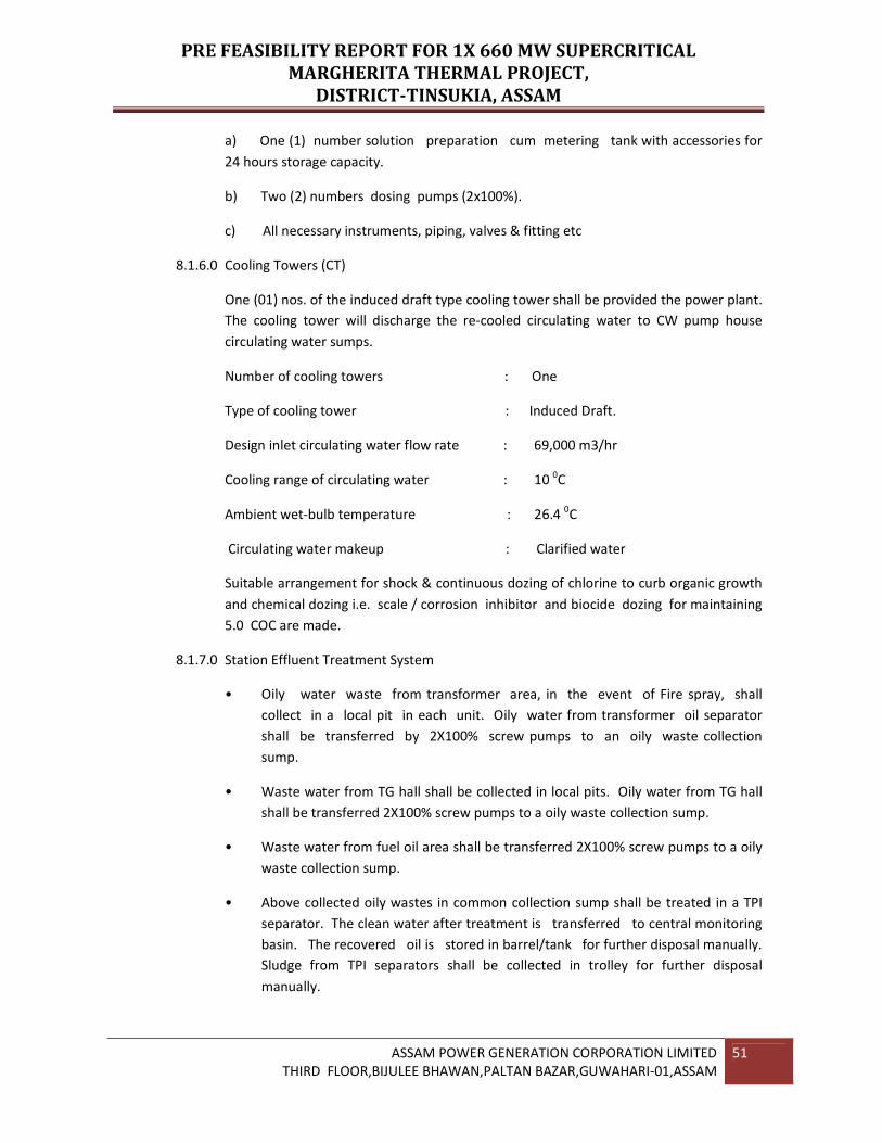
PRE FEASIBILITY REPORT FOR 1X 660 MW SUPERCRITICAL
MARGHERITA THERMAL PROJECT,
DISTRICT-TINSUKIA, ASSAM
ASSAM POWER GENERATION CORPORATION LIMITED
THIRD FLOOR,BIJULEE BHAWAN,PALTAN BAZAR,GUWAHARI-01,ASSAM
51
a) One (1) number solution preparation cum metering tank with accessories for
24 hours storage capacity.
b) Two (2) numbers dosing pumps (2x100%).
c) All necessary instruments, piping, valves & fitting etc
8.1.6.0 Cooling Towers (CT)
One (01) nos. of the induced draft type cooling tower shall be provided the power plant.
The cooling tower will discharge the re-cooled circulating water to CW pump house
circulating water sumps.
Number of cooling towers : One
Type of cooling tower : Induced Draft.
Design inlet circulating water flow rate : 69,000 m3/hr
Cooling range of circulating water : 10 0C
Ambient wet-bulb temperature : 26.4 0C
Circulating water makeup : Clarified water
Suitable arrangement for shock & continuous dozing of chlorine to curb organic growth
and chemical dozing i.e. scale / corrosion inhibitor and biocide dozing for maintaining
5.0 COC are made.
8.1.7.0 Station Effluent Treatment System
• Oily water waste from transformer area, in the event of Fire spray, shall
collect in a local pit in each unit. Oily water from transformer oil separator
shall be transferred by 2X100% screw pumps to an oily waste collection
sump.
• Waste water from TG hall shall be collected in local pits. Oily water from TG hall
shall be transferred 2X100% screw pumps to a oily waste collection sump.
• Waste water from fuel oil area shall be transferred 2X100% screw pumps to a oily
waste collection sump.
• Above collected oily wastes in common collection sump shall be treated in a TPI
separator. The clean water after treatment is transferred to central monitoring
basin. The recovered oil is stored in barrel/tank for further disposal manually.
Sludge from TPI separators shall be collected in trolley for further disposal
manually.

PRE FEASIBILITY REPORT FOR 1X 660 MW SUPERCRITICAL
MARGHERITA THERMAL PROJECT,
DISTRICT-TINSUKIA, ASSAM
ASSAM POWER GENERATION CORPORATION LIMITED
THIRD FLOOR,BIJULEE BHAWAN,PALTAN BAZAR,GUWAHARI-01,ASSAM
52
• The wash water wastes from boiler area shall be collected in a sump and shall be
transferred by 2X100% centrifugal vertical pumps to waste water collection
sump.
• The side stream filter back wash shall be transferred by 2X100% centrifugal
vertical pumps to waste water collection sump.
• The Pre Treatment Plant filter back wash shall be transferred by 2X100%
Centrifugal vertical pumps to waste water collection sump.
• Above collected waste in waste water collection sump shall be treated in
Lamella clarifiers or tube settlers to remove the suspended solids. The clean
water after treatment shall be transferred to central monitoring basin. The sludge
generated shall be further treated in 1X100% thickener.
• A dedicated chemical dosing system with tanks and 2X100% metering pumps
common for lamella clarifier and thickener shall be provided.
• The sludge generated from the lamella clarifier and RO plant clarifier shall be
collected in the sludge sump and shall be transferred to 2X5 m3/hr.
centrifuges. The clear water generated shall be transferred to CMB and the cakes
shall be manually removed.
• Power cycle blow down of each unit shall be collected in a boiler blow down
sump of respective unit and will be transferred to central monitoring basin by
2X100% vertical centrifugal pumps.
• Regeneration waste from neutralization pit in DM Plant area and CPU plant shall
be pumped by 2X100% pumps to central monitoring basin.
• Auxiliary steam condensate from the fuel tank heating line shall be collected in
the fuel oil area oil collection pit.
• The water from central monitoring basin can be used as a make up to ash handling
plant or horticulture with an emergency dump to ash pond.
• It may be noted that, various wastewater generated above are treated either in
TPI separator/Lamella clarifier/tube settler or transferred without any
further treatment to central monitoring basin/other systems. The above
system facility shall remove only oil and suspended solids up to the following
limits:
• Suspended solids : 100 ppm max.
• Oil and grease : 20 ppm max.

PRE FEASIBILITY REPORT FOR 1X 660 MW SUPERCRITICAL
MARGHERITA THERMAL PROJECT,
DISTRICT-TINSUKIA, ASSAM
ASSAM POWER GENERATION CORPORATION LIMITED
THIRD FLOOR,BIJULEE BHAWAN,PALTAN BAZAR,GUWAHARI-01,ASSAM
53
• PH : 6.5 to 8.5
• Plant domestic waste & sanitary water will be collected by gravity to septic tanks
for anaerobic treatment. Sewage is then allowed to pass through as up- flow filter.
During the process, most of COD, BOD and TSS are removed. Overflow from up
flow filters after disinfection using chlorination will be distributed for
horticultural purpose only.
8.1.8.0 Compressed Air Scheme
The compressed air system is comprised of the instrument air system and the service air
system. Instrument air is required for the various pneumatically operated valves
and instruments in the power plant, while service air is required for general plant
services.
Two (2) Nos. identical air compressors (1W+1S) common for instrument air and service
air system is provided. 1 X 100% compressors (common for IA & SA) for the unit and
one (1) standby is provided.
The Capacity of each compressor is 90 NM3/Min at 8.0 Kg/cm
2 (g).
Two (2) nos (1W + 1S) Air Drying Plant at a working pressure of 8.0 Kg/Cm2 (g) shall also
be provided to supply moisture free air to instruments. Air-drying plant capacity shall be
adequate for the IA requirement. Air Drying Plant shall be heat of Compression “HOC”
type. Dew point of air at the outlet of ADP shall be –20 oC at atmospheric pressure.
Six (6) nos Air receivers, i.e., 2 nos. for IA system & 2 nos. for SA system near compressor
house and 2 nos. unit air (IA) receivers in TG building of 10 M3 capacity each shall be
provided, designed and constructed in accordance with the requirement of the ASME
unfired pressure vessel code
8.1.9.0 Condensate Polishing Unit (CPU)
The Condensate Polishing Plant (CPP) shall treat the condensate of the respective
Turbine-Generator (TG) Units of the power station.
The Condensate polishing Plant shall consists of one set of Condensate polishing Unit
(CPU) for the TG unit inside TG Building. Each CPU shall consist of Four (4) service
vessels (Three working & one standby vessel) of 33.33% capacity for the TG Unit.
The regeneration system shall be external and common to the CPU of the TG unit. For
regeneration, resin from the exhausted exchanger vessel will be transferred
hydraulically to this facility. The exhausted resin charge will be cleaned, separated,
regenerated, mixed and rinsed before being stored for the next use.
The common influent and effluent headers of each CPU will be connected to an
automatic bypass line (s). On high pressure signal across the service vessel, the

PRE FEASIBILITY REPORT FOR 1X 660 MW SUPERCRITICAL
MARGHERITA THERMAL PROJECT,
DISTRICT-TINSUKIA, ASSAM
ASSAM POWER GENERATION CORPORATION LIMITED
THIRD FLOOR,BIJULEE BHAWAN,PALTAN BAZAR,GUWAHARI-01,ASSAM
54
automatic control valve(s) in the bypass line(s) shall open, bypassing the service
vessel(s). Make-up water to the turbine cycle will be added to the condenser hot well as
required.
The influent quality during start up may deteriorate to:
Table 8.4
DS Ppb 2000 max
silica Ppb 150 max
Crud Ppb 1000 max
(Mostly black iron oxide)
8.1.10.0 Ventilation & Air-conditioning System
A Central Chilled Water type Air Conditioning Plant with one Vapour Absorption
Machine (VAM) of 100% duty (working) and one screw chilling unit of 100% duty
(standby) shall be provided to cater to the air conditioning requirements of the
following areas.
• Common control room, control equipment rooms, computer room, Relay Panel
& UPS room, SWAS rooms, Analyzer room, C&I maintenance Engineer’s
Room, Record room, AVR, common for both Units of power house building.
• ESP-VFD Control Room
A Central Chilled water type air conditioning plant is provided for air conditioning
of the following areas of Service Building.
• Offices & Meeting Areas
• Instrumentation Lab and office
• Chemical Lab & Office
• Electrical Lab
• Conference Room
• Split type Air Conditioners
Split type air conditioners (air cooled) are provided to cater to the air conditioning
requirements of the following areas of Service Building.
• DM Plant Control Room
• Control Room of Water Treatment Building
• Control Room of Coal Handling Building

PRE FEASIBILITY REPORT FOR 1X 660 MW SUPERCRITICAL
MARGHERITA THERMAL PROJECT,
DISTRICT-TINSUKIA, ASSAM
ASSAM POWER GENERATION CORPORATION LIMITED
THIRD FLOOR,BIJULEE BHAWAN,PALTAN BAZAR,GUWAHARI-01,ASSAM
55
• Control Room of Ash Handling Building
• Stores in-charge room of Ware House
• Computer punching Room of Security & Time Building
Ventilation of the miscellaneous areas and other buildings will be provided as required
for equipment operation and personnel comfort. Toilet and battery areas will be
provided with exhaust fans.
8.1.11.0 Cranes and Hoisting Equipment
One number of 130/30T Capacity EOT crane is envisaged in the T.G. Hall. The crane
will be double box girder, M3 duty, and indoor duty.
8.1.12.0 Fuel Oil System
The Fuel Oil System shall consist of light diesel oil system and heavy fuel oil system to
the steam generator igniters. Light Diesel Oil (LDO) shall be used for initial start up
while heavy Fuel Oil Fuel Oil (LSHS/HPS/HFO Gr HV) shall be used for flame stabilization
and during low load operation.
Normal annual requirement would be based on statistical average of oil
consumption of 3.2 ml of HFO per Kwh of power generation. 15 days of oil storage is
envisaged adequate during trial operation. Total HFO & LDO storage capacity shall be
designed based on these parameters
8.1.13.0 Hydrogen Generation Plant
The Hydrogen Generation Plant shall be of Bi Polar design only having 2 streams (2 x
50 %) of 10 Nm3/hr capacity of H2 Gas Generation is envisaged. The approx.
Hydrogen gas requirement will be about 150 Nm3/day.
8.1.14.0 Fire Protection System
For protection against fire, all yard equipment and plant equipment will be
protected by a combination of hydrant system; automatic sprinkler spray system
(emulsifier system); fixed foam system for oil handling areas; automatic high velocity
and medium velocity sprinkler spray system; auto-modular inert gas based system for
control rooms apart from portable and mobile fire extinguishers located at strategic
areas of plant buildings and adequate Passive Fire Protection measures. The systems will
be designed as per the recommendations of NFPA or approved equals in accordance
with the Tariff Advisory Committee of the Insurance Association of India
stipulations.
8.2.0 Electrical System
8.2.1 Basic Design Concept

PRE FEASIBILITY REPORT FOR 1X 660 MW SUPERCRITICAL
MARGHERITA THERMAL PROJECT,
DISTRICT-TINSUKIA, ASSAM
ASSAM POWER GENERATION CORPORATION LIMITED
THIRD FLOOR,BIJULEE BHAWAN,PALTAN BAZAR,GUWAHARI-01,ASSAM
56
For designing the various electrical systems and equipment the following basic concepts
will be applicable:
• Ambient temperature: The design ambient air temperature will be 500C.
• Voltage levels: Voltage levels in the proposed plant will be 400 KV and 220KV
for Interconnection with grid, 21 KV for 660MW generation. Large Motor
(1500KW and above) like BFP, CWP, ID, PA and supply feeders to Transformer shall
be connected in 11KV Swgr. Motor above 200KW upto 1500KW shall be connected to
3.3KV Swgr. Auxiliary motors of 200KW and below shall be fed in LT. Single phase AC
motors will not be used except in very special cases of low power for which panel
mounted 415/240 volt transformers will be used. For 110 volt AC control supply, if
used, separate panel mounted 415/110 volts transformers will also be used.
• Variations: Voltage variation will be ±10%, frequency variation shall be ±5% and
combined voltage and frequency variation will be ±10%.
• Fault levels: Fault levels for the various voltage systems shall be as under
400 KV 40KA for 1 Sec.
220 KV 40KA for 1 Sec.
11 KV 40KA for 3 Sec.
3.3 KV 40KA for 3 Sec.
415 volt 50KA for 1 Sec.
220 volts D.C 25KA for 1 Sec
• Basic Impulse level: The basic impulse levels will be 1425 KVp for 400 KV, 1050 KVp
for 220 KV, 75 KVp for 11KV System and 45 KVp for 3.3KV system.
• Control and Protection: Controls will be micro-processor based and centralized in
a central control room.
8.2.2 Power Evacuation
8.2.2.1 Transmission Interconnection
One number of double circuit 400kV transmission lines proposed for the
interconnection from power station switchyard up to Mariani Grid sub-station at 400 KV
for evacuation of about 660 MW power from the proposed generating power plant.
One 400 kV switchyard will be constructed in the proposed power plant for evacuation
of power.
8.2.2.2 400KV Switchyard
PRE FEASIBILITY REPORT FOR 1X 660 MW SUPERCRITICAL
MARGHERITA THERMAL PROJECT,
DISTRICT-TINSUKIA, ASSAM
ASSAM POWER GENERATION CORPORATION LIMITED
THIRD FLOOR,BIJULEE BHAWAN,PALTAN BAZAR,GUWAHARI-01,ASSAM
57
A 400kV outdoor Switchyard has been envisaged for evacuation of generated power
through generator transformer from the proposed power plant. This switchyard
will be located in an area separate from the main power house building and will
be surrounded by a fence. The 400 kV outdoor switchyard will be designed with one and
half breaker Scheme. The switchyard will be provided with the following fully equipped
bays:
• 1- Generator transformer bay
• 2- 400 kV outgoing feeder bays
• 1- Station transformer bay
• One Number Spare Feeder Bay (with all equipment)
The switchyard will be of outdoor air insulated type. The switchyards will be provided
with necessary circuit breakers, disconnectors, earthing switches, current transformers,
surge arrestors, lightning arrestors, protective relays etc. Sequential Event Recorder
(SER) of the switchyard signals will be provided. The switchyard bus bars shall have
high speed three phase busbar differential protections with independent check
feature and also over voltage protection. Moreover each bay shall be provided
with local breaker back-up protection. These signals as a minimum will contain all
perspective relays lock out relay and breaker auxiliary contacts. These will be hardwired
to SER cabinet.
8.2.2.3 Switchyard Control Room
The control, monitoring and operation of the 400kV switchyard will be through SCADA in
the Switchyard Control Room. The switchyard will have its own Control Building for
accommodating SCADA system equipment and transmission Line Protection panels and
other Switchyard auxiliary equipment. However SCADA shall be interconnected to
power plant main DCS through serial link (Fibre optic cables) for monitoring purpose.
Separate room will be provided to accommodate batteries for 220V DC System for
control and supervision of the switchyard equipment and 48V DC System for PLCC
system. Separate room will be provided for Tariff Metering Panels.
8.2.3 Power Transformers
8.2.3.1 Generator Step-Up Transformer
The Generator transformer for 660MW unit is of Three No. of single phase,
50HZ, 420/√3 / 21/√3 KV, YNd1, each 275/220/165 MVA, OFAF/ONAF/ONAN cooled oil
immersed outdoor transformer. Generator transformer will be provided with On Load
Tap Changer (OLTC) having tap change range of -12.5% to +7.5% in steps of 1.25%.
Transformers will be provided with requisite protection devices and accessories.

PRE FEASIBILITY REPORT FOR 1X 660 MW SUPERCRITICAL
MARGHERITA THERMAL PROJECT,
DISTRICT-TINSUKIA, ASSAM
ASSAM POWER GENERATION CORPORATION LIMITED
THIRD FLOOR,BIJULEE BHAWAN,PALTAN BAZAR,GUWAHARI-01,ASSAM
58
One number spare single phase transformer will be provided for the unit, which is
normally kept in energized condition.
The isolated phase bus ducts (IPB) will provide interconnection between the generator
and generator circuit breaker and between generator circuit breaker and generator
transformer with tap off to unit transformers
8.2.3.2 Unit Transformer (UT)
The Unit auxiliary transformer for 660MW unit is Two numbers, each Three phase, Two
Winding, 21/11.6 KV 50HZ, Dyn11, 31.5 MVA, ONAF, 25 MVA ONAN, cooled oil
immersed outdoor transformer. Unit transformer will be provided with Off Circuit
Tap Changer (OCTC) having tap change range of ±5% in steps of 2.5%. Transformers
will be provided with requisite protection devices and accessories. LV winding
neutral is grounded through resistor of suitable rating limiting the phase to ground
current to 300A.
8.2.3.3 Start-up Power Arrangement /Station Transformer
One number station transformers, each of three phase, three winding, 90/45/45
MVA ONAF, 72/ 36/36 ONAN cooled, YNyn0, yn0, shall be provided for Start-up power
for the Unit and also caters to station common auxiliary loads.
8.2.4 Service Transformer
8.2.4.1 Unit Auxiliary Transformer (UAT)
Required Nos. of 11kV / 3.3KV adequately rated transformers for supplying the unit
loads and station low voltage loads will be provided. The transformers are sized on
the basis of 2 x 100% rating. These transformers will be provided with off circuit tap
changer + 5% in steps of 2.5%. The auxiliary transformers will be DYn11 connected and
the neutral will be effectively grounded.
These transformers shall be of mineral oil filled type suitable for outdoor location.
8.2.4.2 LT Auxiliary Transformer
Required Nos. of 11kV / 433V adequately rated transformers for supplying the unit
loads and station low voltage loads will be provided. The transformers are sized on
the basis of 2 x 100% rating. These transformers will be provided with off circuit tap
changer + 5% in steps of 2.5%. The auxiliary transformers will be DYn11 connected
and the neutral will be effectively grounded. These transformers shall be
either mineral oil filled type suitable for outdoor location, or dry type suitable for indoor
location.
8.2.5 Switchgears
8.2.5.1 11 KV Switchgear

PRE FEASIBILITY REPORT FOR 1X 660 MW SUPERCRITICAL
MARGHERITA THERMAL PROJECT,
DISTRICT-TINSUKIA, ASSAM
ASSAM POWER GENERATION CORPORATION LIMITED
THIRD FLOOR,BIJULEE BHAWAN,PALTAN BAZAR,GUWAHARI-01,ASSAM
59
11KV switchgear will be metal-clad vertical single front draw-out type for indoor
installation.
Degree of protection shall be IP4X. Breakers will be either SF6 or vacuum type,
suitable for a rupturing capacity of 40 KA, closing and opening time not exceeding 5
and 4 cycles respectively. The breakers will be trip-free with anti-pumping device and
operating mechanism of stored energy type with DC motor operated charging of spring.
Busbar will be SPBD type. Bus bar will be Heat shrinkable PVC sheathed shroud-jointed
and temperature of the bus bar at 500C ambient will be limited to 900C.
8.2.5.2 3.3 KV Switchgear
3.3 KV switchgear will be metal-clad vertical single front draw-out type for indoor
installation.
Degree of protection shall be IP4X. Breakers will be either SF6 or vacuum type,
suitable for a rupturing capacity of 40 KA, closing and opening time not exceeding 5
and 4 cycles respectively. The breakers will be trip-free with anti-pumping device and
operating mechanism of stored energy type with DC motor operated charging of spring.
Bus bar will be SPBD type. Bus bar will be Heat shrinkable PVC sheathed
shroud-jointed and temperature of the bus bar at 50°C ambient will be limited to 90°C.
8.2.5.3 415 Volt Switchgear
415 volt switchgear will be metal clad vertical single/double front draw out type IP54
enclosure class for indoor installation. Panels will be arranged for bottom entry of
cables, as required.
The incomers, ties and motors of 110 KW and above will be controlled by circuit
breakers. Other feeders will be controlled by switch fuse/contactor for motors and
switch fuse for feeders. Circuit breakers will be of air-break type. The rupturing
capacity will be 50 KA.
Bus bar shall be PVC sleeved jointed shrouded and rated for 2500 Amps, or as required,
with total temperature limited to 90oC at 50oC ambient.
8.2.6 Electric Drives
Electrical drives will be 3 phase 50 cycle squirrel cage energy efficient type
induction motors operating at nominal voltages of 11000V, 3300V and415V Motors
will be of high power factor (at least 0.85 for large motors), F class insulation,
IP55 enclosure class (with canopy for vertical outdoor motors), designed for
direct-on-line starting with as low starting current as possible.
Starting current for boiler feed pumps, and CW pumps shall not exceed 6.0 times (With
no positive tolerance) the full load current.
PRE FEASIBILITY REPORT FOR 1X 660 MW SUPERCRITICAL
MARGHERITA THERMAL PROJECT,
DISTRICT-TINSUKIA, ASSAM
ASSAM POWER GENERATION CORPORATION LIMITED
THIRD FLOOR,BIJULEE BHAWAN,PALTAN BAZAR,GUWAHARI-01,ASSAM
60
Motor rating will be at least 1.15 times the consumption at the duty point of the driven
equipment.
Motors will be capable of starting and accelerating to full speed at 80% of the
nominal voltage For BFP pump the motor shall be capable of starting at 70% of
Nominal voltage. And will be capable of either two starts in quick succession with third
start after 5 minutes. In cold condition or two start at 15 minutes intervals in hot
condition, both cases with voltage and frequency variation limits. Motors will also be
capable of restarting under full load after a momentary loss of voltage with the
possibility of application of a total of 150% nominal voltage.
Motor torque characteristic will be such as to ensure smooth and rapid starting and
acceleration of the driven equipment. Motors will be provided with suitable heating
arrangement while at standstill.
8.2.7 Protection
Electrical protection proposed for the various equipment shall be generally as indicated
below:
8.2.7.1 Generator and Generator Transformer
Generator:
• Differential (87G)
• Inter-turn fault (95)
• Stator earth fault (64G)
• Loss of excitation (40)
• Negative sequence current (46)
• Reverse power (32)
• Low forward power (37)
• Rotor earth fault (64R)
• Over-voltage (59)
• Under-voltage (27)
• Generator pole Slipping (98)
• Under frequency (81U)
• Over Frequency (81O)

PRE FEASIBILITY REPORT FOR 1X 660 MW SUPERCRITICAL
MARGHERITA THERMAL PROJECT,
DISTRICT-TINSUKIA, ASSAM
ASSAM POWER GENERATION CORPORATION LIMITED
THIRD FLOOR,BIJULEE BHAWAN,PALTAN BAZAR,GUWAHARI-01,ASSAM
61
• Voltage balance (60)
• Overload (50)
• Backup impedance (21G)
• Inverse time over current (51)
• Thermal Over load(49)
• Over fluxing (99)
• Dead Machine Protection (50GDM)
• Rate of Change of Frequency (df/dt) - Stage-1
• Rate of Change of Frequency (df/dt) - Stage-2
Generator Transformer:
• Generator, Generator transformer, UT overall differential protection (87GT)
• Generator transformer Backup Earth Fault Protection (51NGT)
• Generator transformer Differential Protection (87T)
• HV Restricted Earth Fault Protection (64RGT)
• Over fluxing Relay
• Buchholz Relay
• Winding Temperature
• Oil Temperature
• Pressure Relief Device operation
• Master Trip Relay (86)
• Tripping relays for protection devices of Generator Transformer (GT) and 63X /49X
for multiplying the contacts of protections.
For trip function (63X1/49X1)
- GT buchholz II stage (63TX)
- GT winding temperature very high (49 WTX)
- GT oil temperature very high (49 OTX)
- GT pressure relief device operated (63 PTX)

PRE FEASIBILITY REPORT FOR 1X 660 MW SUPERCRITICAL
MARGHERITA THERMAL PROJECT,
DISTRICT-TINSUKIA, ASSAM
ASSAM POWER GENERATION CORPORATION LIMITED
THIRD FLOOR,BIJULEE BHAWAN,PALTAN BAZAR,GUWAHARI-01,ASSAM
62
- GT fire protection trip (FRTX) for annunciation function (63x2/49x2)
- GT Buchholz I stage (63AX)
- GT winding temperature high (49 WAX)
- GT oil temperature high (490AX)
- GT oil level low (OLAX)
- Cooler supply failure
- Cooler trouble
8.2.7.2 Unit Transformer Protection
• Unit Transformer differential protection (87 UT)
• Unit Transformer Backup earth fault protection on the LV side (51NUT)
• HV inverse time over current Protection (51UT)
• HV Phase Instantaneous Over Current (50UT)
• Restricted Earth Fault Protection (64RUT)
• Buchholz Relay
• Winding Temperature
• Oil Temperature
• Pressure Relief Device operation
• OCTC surge protection.
• Master Trip Relay (86)
• Tripping relays for protection devices of Unit Transformer (UT) and 63X / 49X for
multiplying the contacts of protections.
1For trip function (63X1/49X1)
- UT buchholz II stage (63TX)
- UT winding temperature very high (49 WTX)
- UT oil temperature very high (49 OTX)
- UT pressure relief device operated (63 PTX)
- UT fire protection trip (FRTX)

PRE FEASIBILITY REPORT FOR 1X 660 MW SUPERCRITICAL
MARGHERITA THERMAL PROJECT,
DISTRICT-TINSUKIA, ASSAM
ASSAM POWER GENERATION CORPORATION LIMITED
THIRD FLOOR,BIJULEE BHAWAN,PALTAN BAZAR,GUWAHARI-01,ASSAM
63
2For annunciation function (63x2/49x2)
- UT Buchholz I stage (63AX)
- UT winding temperature high (49 WAX)
- UT oil temperature high (490AX)
- UT oil level low (OLAX)
- Cooler supply failure
- Cooler trouble
8.2.7.3 Station Transformer Protection
• Station Transformer differential protection (87 ST)
• Stationt Transformer Backup earth fault protection on the LV side
(51NS)
• HV Phase Instantaneous Over Current (50ST)
• Restricted Earth Fault Protection (64RST)
• Buchholz Relay
• Winding Temperature
• Oil Temperature
• Pressure Relief Device operation
• OLTC surge protection.
• Master Trip Relay (86)
• Tripping relays for protection devices of Station Transformer (UT) and 63X / 49X for
multiplying the contacts of protections.
1For trip function (63X1/49X1)
- ST buchholz II stage (63TX)
-ST winding temperature very high (49 WTX)
- ST oil temperature very high (49 OTX)
- ST pressure relief device operated (63 PTX)
- ST fire protection trip (FRTX)

PRE FEASIBILITY REPORT FOR 1X 660 MW SUPERCRITICAL
MARGHERITA THERMAL PROJECT,
DISTRICT-TINSUKIA, ASSAM
ASSAM POWER GENERATION CORPORATION LIMITED
THIRD FLOOR,BIJULEE BHAWAN,PALTAN BAZAR,GUWAHARI-01,ASSAM
64
2 For annunciation function (63x2/49x2)
- ST Buchholz I stage (63AX)
- ST winding temperature high (49 WAX)
- ST oil temperature high (490AX)
- ST oil level low (OLAX)
- Cooler supply failure
- Cooler trouble
8.2.7.4 3.3 KV Unit auxiliary transformer protection
All transformer protection as applicable for station transformer shall be provided for the
unit auxiliary transformer
LT Auxiliary Transformer Protection
For LT Auxiliary Transformer (oil filled) protection system shall be provided with
following protective devices
• Over current relay (50/51)
• Earth Fault Relay (50N/51N)
• Restricted Earth Fault Protection (64R)
• Standby Earth Fault (51NT)
• Tripping relays for protection devices of Distribution Transformer and 63X /
49X for multiplying the contacts of protections.
• For trip function (63X1/49X1)
- Buchholz II stage (63TX)
- Winding temperature very high (49 WTX)
- Oil temperature very high (49 OTX)
- Pressure relief device operated (63 PTX)
- Fire protection trip (FRTX)
• For annunciation function (63x2/49x2)
- Buchholz I stage (63AX)

PRE FEASIBILITY REPORT FOR 1X 660 MW SUPERCRITICAL
MARGHERITA THERMAL PROJECT,
DISTRICT-TINSUKIA, ASSAM
ASSAM POWER GENERATION CORPORATION LIMITED
THIRD FLOOR,BIJULEE BHAWAN,PALTAN BAZAR,GUWAHARI-01,ASSAM
65
- Winding temperature high (49 WAX)
- Oil temperature high (490AX)
- Oil level low (OLAX)
For Dry type transformer the protective devices shall be as above with
modification.
8.2.7.5 Incoming (Source) Breakers.
Each incoming (source) breaker shall be provided with numerical feeder
management type devices. These devices shall be multi-element type or multi- function
devices comprising of the following protective elements:-
• Over current (50/51) for phase fault with timer (2)
• Over current (50N/ 51N) for earth fault with timer (2)
• Standby earth fault (51SN) (for incomer from transformer only)
• Restricted earth fault (64) (for incomer from transformer only)
• Under voltage with time delay (27)
• VT fuse failure
8.2.7.6 Tie Circuit Breaker
Each tie-breaker shall be provided with –
1. One multifunctional relay comprising of following protective elements
• Over current (50/ 51) for phase fault with timer (2)
• Over current (50N/ 51N) for earth fault with timer (2)
• Under voltage with time delay (27)
• VT fuse failure
2. One numerical synchronizing check relay, if applicable, complete with guard relay and
hardwires.
8.2.7.7 Motor Feeder
Each motor feeder shall be provided with –
1. One numerical Motor Protection Relays to detect and take appropriate action
against the following

PRE FEASIBILITY REPORT FOR 1X 660 MW SUPERCRITICAL
MARGHERITA THERMAL PROJECT,
DISTRICT-TINSUKIA, ASSAM
ASSAM POWER GENERATION CORPORATION LIMITED
THIRD FLOOR,BIJULEE BHAWAN,PALTAN BAZAR,GUWAHARI-01,ASSAM
66
• Thermal over load (49)
• Phase fault (50)
• Unbalance (-Ve seq.)(46)
• Locked rotor (50LR)
2. One Definite time O/C relay (50G) for earth fault (through CBCT)
3. Differential protection (87) for motor rated above 1000 kW rating
8.2.7.8 LT Switchgear
415 Volt PCC
1. The minimum protections to be provided for different types of circuits are listed
below:
a. Incoming Feeder: O/C relays (50/51) for phase fault with timer (2) O/C relay
(50N/51N) for Earth fault with timer (2). Under voltage relay (27)
b. Outgoing Bkr. Feeder : O/C relays (50/51) for phase fault with timer (2) O/C relay
(50N/51N) for Earth fault with timer (2).
2. Apart from protection relays, each electrically operated breaker shall be provided
with antipumping (94), trip annunciation (30), lockout (86), lockout
supervision (95) and trip supervision (74) relays. Lockout relay shall be hand
reset type.
3. Fuse monitoring relay (98) shall be provided on the secondary side of voltage
transformer to monitor fuses.
8.2.7.9 415 Volt MCC & DB
1. The minimum protections to be provided for different types of circuits are listed
below:
a. Incoming Feeder: O/C relays (50/51) for phase fault with timer (2) O/C relay
(50N/51N) for Earth fault with timer (2). Under voltage relay (27)
b. Outgoing motor Feeder: O/C relays (50/51) for phase fault with timer (2) O/C relay
(50N/51N) for Earth fault with timer (2).
c. Contactor operated unidirectional motor feeders
• Short circuit protection by HRC fuses.
• Thermal over load relay (hand re set type) with built in single phasing
preventer
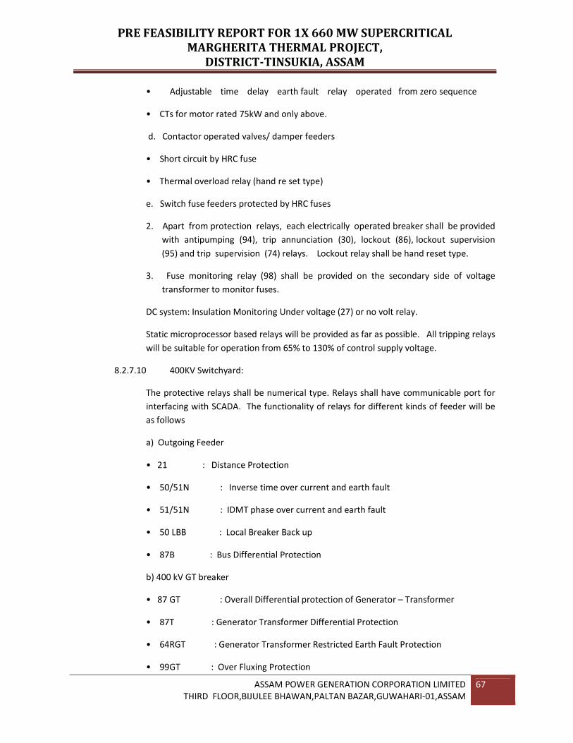
PRE FEASIBILITY REPORT FOR 1X 660 MW SUPERCRITICAL
MARGHERITA THERMAL PROJECT,
DISTRICT-TINSUKIA, ASSAM
ASSAM POWER GENERATION CORPORATION LIMITED
THIRD FLOOR,BIJULEE BHAWAN,PALTAN BAZAR,GUWAHARI-01,ASSAM
67
• Adjustable time delay earth fault relay operated from zero sequence
• CTs for motor rated 75kW and only above.
d. Contactor operated valves/ damper feeders
• Short circuit by HRC fuse
• Thermal overload relay (hand re set type)
e. Switch fuse feeders protected by HRC fuses
2. Apart from protection relays, each electrically operated breaker shall be provided
with antipumping (94), trip annunciation (30), lockout (86), lockout supervision
(95) and trip supervision (74) relays. Lockout relay shall be hand reset type.
3. Fuse monitoring relay (98) shall be provided on the secondary side of voltage
transformer to monitor fuses.
DC system: Insulation Monitoring Under voltage (27) or no volt relay.
Static microprocessor based relays will be provided as far as possible. All tripping relays
will be suitable for operation from 65% to 130% of control supply voltage.
8.2.7.10 400KV Switchyard:
The protective relays shall be numerical type. Relays shall have communicable port for
interfacing with SCADA. The functionality of relays for different kinds of feeder will be
as follows
a) Outgoing Feeder
• 21 : Distance Protection
• 50/51N : Inverse time over current and earth fault
• 51/51N : IDMT phase over current and earth fault
• 50 LBB : Local Breaker Back up
• 87B : Bus Differential Protection
b) 400 kV GT breaker
• 87 GT : Overall Differential protection of Generator – Transformer
• 87T : Generator Transformer Differential Protection
• 64RGT : Generator Transformer Restricted Earth Fault Protection
• 99GT : Over Fluxing Protection

PRE FEASIBILITY REPORT FOR 1X 660 MW SUPERCRITICAL
MARGHERITA THERMAL PROJECT,
DISTRICT-TINSUKIA, ASSAM
ASSAM POWER GENERATION CORPORATION LIMITED
THIRD FLOOR,BIJULEE BHAWAN,PALTAN BAZAR,GUWAHARI-01,ASSAM
68
• 50/51 : Instantaneous & IDMT phase over current
• 51N : Inverse time Earth fault
• 87B : Bus differential protection
• 67 : Directional Phase Over current
• 67N : Directional Earth fault
• 50LBB : Local Breaker Back up
c) 400 kV ICT breaker
• 87 ST : Station Transformer Differential protection
• 99ST : Station Transformer over Fluxing Protection
• 50/51 : Instantaneous & IDMT phase over current
• 51N : Inverse time Earth fault
• 64RST : Restricted Earth fault protection for both LV & HV Side
• 51NT : Standby earth fault protection for both LV & HV side
• 87B : Bus differential protection
• 67 : Directional phase over current
• 67N : Directional Earth fault
• 50LBB : Local Breaker Back up
d) Line Reactor
• 87 R : Differential protection relay for Reactor
• 50/51 : Instantaneous & IDMT phase over current
• 51N : Inverse time Earth fault
• 50LBB : Local Breaker Back up
• 21R : Back Impedance Relay
8.2.8.0 Control Room
There will be a centralized control room at the operating floor of steam turbine
generator building in which control panels for the steam generator, steam turbine and

PRE FEASIBILITY REPORT FOR 1X 660 MW SUPERCRITICAL
MARGHERITA THERMAL PROJECT,
DISTRICT-TINSUKIA, ASSAM
ASSAM POWER GENERATION CORPORATION LIMITED
THIRD FLOOR,BIJULEE BHAWAN,PALTAN BAZAR,GUWAHARI-01,ASSAM
69
generator, auxiliary power supply, will be housed. This will also house the Data
Acquisition System equipment and fire alarm control panel.
400KV Switchyard controls will be provided in the switchyard control room. Control
panels will be a combination of upright panels and separately mounted control desks
with TFT.
8.2.9.0 DC System
8.2.9.1 220V DC system
A separate 220 V DC system for each unit for plant auxiliary system and 01 220 V DC
system for switch yard will be provided. Each DC system shall be complete with
02 of 100 % capacity Heavy duty plante (HDP) type battery sets with float and float-
cum-boost charges.
DC system will generally supply for the following:
• Emergency Lube Oil Pump, Jacking Oil Pump, etc(DC)
• Emergency Lighting (DC)
• Switchgear Control
8.2.9.2 24V DC System
A separate 24V DC System is considered for Each Unit, comprising battery, battery
charger and DC distribution board shall be provided to cater the requirement of DDCMIS
system cubicles, cards and transmitters etc.
8.2.9.3 48V DC System
A separate 48V DC System is considered for Switchyard, comprising battery,
battery charger and DC distribution board shall be provided to cater the
requirement of PLCC system.
8.2.10 Uninterruptible power supply (UPS)
An uninterrupted power supply (UPS) system would be provided to cater to 240V AC,
single phase, 50 Hz, 2 wire power supply requirements of instrumentation and control
systems viz. man-machine interface equipment, analyzers, receiver instruments of
each units, PA & EPBAX system etc.. Separate UPS of sufficient capacity shall be
provided for offsite PLC system.
8.2.11 Power and Control Cables
Power cables (AC and DC) will be aluminum conductor, stranded, XLPE insulated,
screened, armored and FRLS sheathed. Power cables shall be 11 KV and 3.3 KV UE
grade. Control cables will be 1100 volt grade multi-core, stranded, copper

PRE FEASIBILITY REPORT FOR 1X 660 MW SUPERCRITICAL
MARGHERITA THERMAL PROJECT,
DISTRICT-TINSUKIA, ASSAM
ASSAM POWER GENERATION CORPORATION LIMITED
THIRD FLOOR,BIJULEE BHAWAN,PALTAN BAZAR,GUWAHARI-01,ASSAM
70
conductor, PVC insulated PVC sheathed, armoured and overall PVC/FRLS sheathed with
minimum 2.5 mm2 conductor size.
Special cables will be used wherever so required for special applications.
8.2.12 Grounding & Lightning Protection
The system grounding envisages generator neutral earthing through secondary
resistance loaded distribution transformer, 400KV system and 415 V system solidly
earthed, 11 KV and 3.3 KV neutral earthed through high resistance to facilitate
ground fault relaying and transient over-voltage reduction.
A separate grounding system for power plant and switch yard shall be provided for
grounding of equipment and structures maintaining step and touch potentials within the
safe limits.
However these two systems will be interconnected at appropriate points. Earth mat will
be provided throughout the power plant. Separate Earth pits for Electronic earthing,
Transformers, Chimney and Cooling Towers etc. shall be provided Lightning protection
for building/structures/equipment such as chimney, cooling tower etc. will be provided.
8.2.13 Lighting
Lighting system will be with 240 volt AC for normal lighting and 220 volt DC for
emergency lighting. Normal AC lighting will be from 415V AC 3 phase, 4 wire
supply through lighting transformers. At least 20% of the normal lighting fixtures will
be connected from the emergency lighting distribution board for automatic
changeover.
Illumination levels at various places will be according to international practice. Basically
indoor illumination will be with fluorescent fittings.
Mercury vapour lamps will be used in areas like the turbine hall. Outdoor
illumination will be achieved by Sodium vapour or mercury vapour in combination with
flood lights.
8.2.14 Emergency Diesel Generator
To enable the unit to shut down safely during complete AC supply failure in the
station, certain important plant auxiliaries will be provided with a reliable AC power
supply through a separate source. For this purpose, Emergency Diesel generator
station should be provided..
Emergency power derived from the Diesel Generator is used for essential services and
safe shut down and battery charging in the event of total black out.
8.3.0 Instrumentation and Controls

PRE FEASIBILITY REPORT FOR 1X 660 MW SUPERCRITICAL
MARGHERITA THERMAL PROJECT,
DISTRICT-TINSUKIA, ASSAM
ASSAM POWER GENERATION CORPORATION LIMITED
THIRD FLOOR,BIJULEE BHAWAN,PALTAN BAZAR,GUWAHARI-01,ASSAM
71
Plant Control & Instrumentation provide a simple effective and fail-safe means for
reliable and efficient operation of the plant under dynamic conditions and for
attainment of maximum station availability. To achieve this objective, Control and
Monitoring facilities are designed so that operation of the Boiler, Turbine, and
Generator along with their major auxiliaries would be accomplished from a CCR
(Central Control Room). From the CCR, operators would start-up, load, unload,
release for remote dispatch, shutdown and monitor the steam generator, turbine and
other auxiliaries of the plant. To fulfill the above functional requirements, a
Distributed Digital Control, Monitoring and Information System (DDCMIS) with TFT /
Keyboard operation for SG and TG controls and hard-wired back-up controls with
monitoring and controlling devices needed for operation is envisaged. All field
instruments like transmitters for Temperature, Flow, Pressure, Level and
Differential pressure are of Smart type with HART Protocol.
For systematic and sequential start-up / shutdown and safe operation of Boiler, Burner
Management System (BMS) with fail-safe cards has been envisaged and shall be part of
DDCMIS.
All the control packages of Turbine-Generator, Boiler and their auxiliaries are
preferably of the integral part of DDCMIS and from same family of hardware. In case
micro-processor based TG and SG controls are from separate vendors, then the same is
hooked-up to DDCMIS through necessary interfacing units.
DDCMIS system configuration Scheme for Unit – I (Typical for Unit – II) &
Common System Between two Units are enclosed in the Drawing No:
8.3.1.0 Plant Control & Monitoring Philosophy
The control and Monitoring philosophy envisaged Control from two Locations:
i. From Unit Control Room (UCR)
ii. From Local Control Station for Offsite & auxiliary plants
8.3.1.1 Control & Monitoring From UCR
TFT Operation
i. All equipment associated with the steam generator viz., Burner
Management System (BMS), Boiler start up system, Feed water system, Steam
temperature Control system (STC), Auxiliary Pressure Reducing and
Desuperheating Station (APRDS), HP bypass system, Primary / Secondary air
system, fuel oil system, Flue gas system, HP dosing system, Soot Blower
System etc., are envisaged to be operable from TFT stations mounted on the Unit
Control Desk (UCD).

PRE FEASIBILITY REPORT FOR 1X 660 MW SUPERCRITICAL
MARGHERITA THERMAL PROJECT,
DISTRICT-TINSUKIA, ASSAM
ASSAM POWER GENERATION CORPORATION LIMITED
THIRD FLOOR,BIJULEE BHAWAN,PALTAN BAZAR,GUWAHARI-01,ASSAM
72
ii. All equipment associated with Turbine Generator viz, Automatic Turbine Run up
System (ATRS), Turbine Electro-hydraulic governing control system(EHG),
Automatic Turbine Tester(ATT), LP bypass system, Gland steam control
system(GSC), Main steam / Extraction steam system, Condensate system,
Heater drains and vent system, LP dosing system, etc., are to be operated from TFT
stations mounted on the UCD.
iii. All the balance of main plant equipment, auxiliaries, valves and dampers shall be
operable from bank of TFT stations on the UCD.
iv. Selection facility such as Auto / Manual and standby for equipment are provided in
the TFT stations.
8.3.1.2 Operation from Hardwired Unit Control Panel (UCP)
i. Steam Generator, Turbine Generator and their Auxiliaries.
ii. In addition to TFT / KBD operation, emergency manual shutdown facility is provided
on the Unit Control Panel (UCP) for manual trip of the Steam generator, Steam
Turbine and major auxiliaries.
8.3.2 Control & Monitoring from Local Stations
a) Main plant Drives
Local emergency stop push buttons shall be provided for all main plant pumps and fans.
Local open / close / stop push buttons with remote / local facility shall be provided as an
integral part of valve actuators for all motor operated isolating and bypass valves and
dampers, except solenoid valves and solenoid operated drives.
b) Utility Plants
Utilities such as Ash handling system, Instrument / Service air compressors,
Coal handling system and Water Treatment Plant shall be operated automatically
from PLC based local control systems with serial link to DDCMIS for monitoring.
c) Common Auxiliaries such as CW, ACW, DMCWP, CT fans, Fuel oil system, CW
make up system etc. shall be controlled from common DDCMIS provided with
Local/remote I/O cabinets as applicable with facility for local/remote control.
8.3.3 Control Processor
Distributed Digital Control, Monitoring and Information System (DDCMIS) shall comprise
of Modulating Control, Sequence Control, Interlocking and Protection, Monitoring and
Information System, Data Archiving, Performance Calculation, and Operator Interfacing
Units.

PRE FEASIBILITY REPORT FOR 1X 660 MW SUPERCRITICAL
MARGHERITA THERMAL PROJECT,
DISTRICT-TINSUKIA, ASSAM
ASSAM POWER GENERATION CORPORATION LIMITED
THIRD FLOOR,BIJULEE BHAWAN,PALTAN BAZAR,GUWAHARI-01,ASSAM
73
The micro-processor based distributed digital control system shall have Multi
tasking Controllers envisaged in complete redundant mode and has the capability to
perform the following tasks either separately or in a combined form:
1) Open loop control (binary)
2) Closed loop control (analog modulating)
3) Plant monitoring/signal acquisition and processing
The micro-processor based system has the capability to perform the above tasks either
separately or in a combined form. As multi-function controllers have a number of
control functions and are preferred to be in completely redundant mode, security of
control functions including those of protection would be maintained even with the loss
of the active controller as well as the functions could be taken over by standby
controller.
8.3.3.1 Non-redundant Signal Acquisition and Processing Modules for Monitoring
Functions
Primary instruments for monitoring functions are provided separate from those for
control tasks. Keeping this segregation of field instruments, the system philosophy could
adopt separate controllers for monitoring tasks. Monitoring task being less critical
compared to control tasks; the controllers for monitoring could be Non- redundant.
Alternatively, as the hardware for monitoring functions is generally similar/
identical to those for the control tasks, it is possible to combine the monitoring
portions with control tasks. However, in view of the general practice of control
engineering, separate non- redundant controllers shall be provided for this function.
8.3.3.2 Controller Task Allocations
The system has overall control tasks having appropriate redundancy built in for all the
system functions both at processor and peripheral level. No failure of any single
peripheral or processor leads to any system function being lost.
For the system with multi-function controllers, functional distribution is adopted and
geographically, the system can be centralized.
Each functional group consists of dedicated microprocessors including redundancy and
dedicated input and output processing. The redundant multifunctional controllers
are in a hot back up mode. The back-up controller takes over the function of the failed
processor within one loop cycle time.
Following segregation for regulating controls is proposed: -
1) Coordinated controls and Fuel feed control

PRE FEASIBILITY REPORT FOR 1X 660 MW SUPERCRITICAL
MARGHERITA THERMAL PROJECT,
DISTRICT-TINSUKIA, ASSAM
ASSAM POWER GENERATION CORPORATION LIMITED
THIRD FLOOR,BIJULEE BHAWAN,PALTAN BAZAR,GUWAHARI-01,ASSAM
74
2) Air flow and excess air correction.
3) Furnace draft.
4) Mill related controls such as air flow/feeder rate/outlet temperature controls.
5) Deaerator level/pressure, hot well level
6) SH steam temperature control
7) RH steam Temperature control
8) HP/LP heaters
9) Secondary air damper control
Segregation further depends upon I/O handling capacity of controller.
Other loops of the plant e.g. miscellaneous loops can be distributed amongst the above
controllers.
Each group has sufficient spare capacity of at least 25% to meet modification / extension
of the system. Multi-function controllers can incorporate the corresponding
interlocks (open loop control tasks of the system). Interlock and modulating controls
are to be so assigned to the controllers in such a way that failure of any controller does
not lead to shut down of the entire unit.
The loop timing from input status change to output contact actuation does not
exceed 50 msecs for protective functions and 100 msecs for the interlock and
sequential control tasks.
While allocating control tasks for Interlock Protection, following criteria are also to be
satisfied: -
1) Left and right air-flue gas paths do not share controllers.
2) Left and right water paths do not share redundant controllers.
3) Those auxiliaries who are common to both paths will be resident in the
controllers of the left / right paths so that both paths will not be lost due to the
failure of a controller.
4) The Air and Water paths do not share controllers.
The system has capability to provide held contact, maintained contact or a held
contact till completion of the control action. Further system has the capability of
either torque or position seating of the valves/dampers.
8.3.3.3 Automation

PRE FEASIBILITY REPORT FOR 1X 660 MW SUPERCRITICAL
MARGHERITA THERMAL PROJECT,
DISTRICT-TINSUKIA, ASSAM
ASSAM POWER GENERATION CORPORATION LIMITED
THIRD FLOOR,BIJULEE BHAWAN,PALTAN BAZAR,GUWAHARI-01,ASSAM
75
In addition to the normal protection interlock and sequential control open loop
tasks, the control system may be implemented to provide a high degree of
automated operation of the plant. The automation system tasks include requisite
sequencing for start-up, raising the load to target load, emergency safe shut down etc.
under various conditions.
8.3.3.4 Automation System Philosophy
The system envisaged is based on modern network orientation and is totally flexible in
its adaptability to process structures, to the safety and availability requirements of main
and auxiliary plants and the communication needs of the user.
Typical loop cycle times for critical control loops like Furnace Draft, Feed Water
Control and Air Flow would be < 100 msecs & rest of < 250 msecs.
The control system has the following four functions:-
1) Signal Conditioning (I/O System)
2) Control functions
3) Man-Machine interface
4) System communication
8.3.4 Central Control room
Central Control room will be partitioned into different rooms to house the
following equipment:
i. Unit control panel (UCP), Unit Control desk (UCD) and printers (SOE /logging /
alarm) in the main control room.
ii. The C&I system cabinet shall consists of electrical auxiliary cabinets, steam
generator and turbine auxiliary system cabinets in the unit electronic cubicle
room.
iii. Steam and water analyzing system (S W A S) room.
iv. Graphic (Color) printers
v. Character alarm printers
vi. Line printer for logs
8.3.5 Operating Stations
a) Main Control Console

PRE FEASIBILITY REPORT FOR 1X 660 MW SUPERCRITICAL
MARGHERITA THERMAL PROJECT,
DISTRICT-TINSUKIA, ASSAM
ASSAM POWER GENERATION CORPORATION LIMITED
THIRD FLOOR,BIJULEE BHAWAN,PALTAN BAZAR,GUWAHARI-01,ASSAM
76
i) The main control console provides the primary man-machine interface through the
operator station. In DDCMIS for the Unit – I, the station consists of Seven (6) sets of
utility TFTs and keyboards in which two (2) operator station for Boiler & Auxiliaries,
Three (3) for Turbine & Auxiliaries and one (1) for Electrical. Four (4) numbers of LVS
for monitoring for the unit. The above setup is typical for Unit – II. The TFT units are of
interactive type, providing the operator with the ability to issue commands via.
Through keyboards. Overview of the plant systems, complete controls and
monitoring of the plant equipment and parameters, including performance of
start-up/shutdown, normal plant operation and emergency operations, are accessible
from any one of the TFT units. In addition, one system is provided for vibrations
monitoring system, one system for Burner Management System and one more system
for Turbine stress control system (TSC).
Each OWS will consist of Operator Terminals (OT) based on latest PC or Work
Station with redundant communication link, 21” Color Graphic (TFT) Monitor, and
QWERTY Keyboard and Optical mouse. 1 No. of Color Laser Printer for Graphics, 1 no.
of B/W Laser Printer for log and 1 no. of B/W Dot Matrix printer for Alarm are
connected in network along with main control consoles.
Equipment status, start permissive check and step-by-step instructions are displayed on
the TFT screens for guiding the operator during various plant and equipment start-up
and shutdown operations. On a plant fault, system trouble or equipment mal-function,
necessary operating instructions are displayed automatically to direct the operator to
alleviate the abnormal conditions. These operator guides are of intelligent, easy to
follow and designed to enhance plant availability.
ii) Shift Supervisor Station:
The shift supervisor station of Unit – I & II each consists of 1 No. of TFTmonitor, 1 no of
Optical Mouse and one Keyboard.
b) C&I Station (Computer Room / Engineer Room):
The computer room/engineer room is located adjacent to the unit control room to
provide easy access for control room personnel. This room contains all Distributed
Digital Control, Monitoring and Information System (DDCMIS) related equipment
necessary for configuring and maintaining the power block as follows:-
i) Main Control Console of the unit consists of one nos of Engineering Station with
DVD Read / Writer and one network color laser printer and 1 No. of Performance
Calculations System with B/W Laser Printer, 1 No. of Historical Storage and Retrieval
System with DVD Read / Writer and 1 no. of B/W Laser Printer, 1 No. of Sequence of
Events System with 1 no. of B/W Laser Printer and 1 No. of Smart Transmitter
Monitoring Station with B/W Laser Pinter, 1 No. of Continuous Emission

PRE FEASIBILITY REPORT FOR 1X 660 MW SUPERCRITICAL
MARGHERITA THERMAL PROJECT,
DISTRICT-TINSUKIA, ASSAM
ASSAM POWER GENERATION CORPORATION LIMITED
THIRD FLOOR,BIJULEE BHAWAN,PALTAN BAZAR,GUWAHARI-01,ASSAM
77
Monitoring System(CEMS), 1 No. of Boiler tube leakage detector system with 1 No.
of B/W laser printer,1 No. of SWAS with 1 no. of B/W laser printer for the Unit.
ii) Engineer workstation with 21” TFT / QWERTY Keyboard console and all
programming devices for configuration of the system and graphics.
iii) Computer cabinet and Floppy Discs / Cartridge Magnetic Tape / Pen drives for the
storage, retrieval, handling and transfer of the system data.
c) Common Unit - BOP
The Common system shall consists of 1 no of Chief Engineer station with one color
Laser printer, 2 no’s of Operating station, 1 no of LVS, 1 no of Management
Information System with B/W Laser Printer, 1 no of ES System with Color Laser Printer,
1 no. of Historical Storage and Retrieval System, 1 no of Closed Circuit Television, 1 no
of OPC client server redundant station and 1 no of ERP station with B/W Laser printer.
8.3.6 Redundancy in I/O
100% redundancy shall be provided for all input/output cards, used for executing closed
loop/sequential interlock functions. Redundant cards are not envisaged data acquisition
/monitoring functions
Redundancy at following level is provided: -
i. CPU
ii. Bus (Data Highway)
iii. I/O
iv. Power supply
100% redundancy shall be provided for critical I/Os, used for executing closed loop /
sequential interlock functions. Redundant cards are not envisaged data acquisition/
monitoring functions.
8.3.7 Steam Generator and Auxiliaries Control
The control system provides a simple effective fail safe means for reliable and
efficient operation of the steam generator with its associated auxiliaries for
attainment of maximum availability and maintaining plant parametric values at
desired controlled levels. The main controls for the steam generator essentially
comprise of the following:
1. Coordinated master control system
2. Combustion control

PRE FEASIBILITY REPORT FOR 1X 660 MW SUPERCRITICAL
MARGHERITA THERMAL PROJECT,
DISTRICT-TINSUKIA, ASSAM
ASSAM POWER GENERATION CORPORATION LIMITED
THIRD FLOOR,BIJULEE BHAWAN,PALTAN BAZAR,GUWAHARI-01,ASSAM
78
2.1 Fuel flow control
2.2 Air flow control
3. Furnace draft control
4. Feed Water & recirculation control (Boiler start up control)
5. Superheated steam temperature control
6. Reheat steam temperature control
7. Mill Temperature Control
8. CBD tank level control
9. Soot blower system pressure control
10. PRDS control
11. Secondary air damper control
12. Primary Air header pressure control
13. Cold end average temperature control for air preheaters
8.3.8 Binary Controls
Binary logic controls are envisaged for the sequence, protection and interlock
operation of major plant auxiliaries. Some of the major auxiliaries / drives are:
1. ID fans
2. FD fans
3. PA fans
4. Mill Systems
5. Seal air fans
6. Reheater protection
7. BMS/FSSS
8. SH/RH spray – block valves and isolation valves
9. LFO, HFO pump
10. Feed water circulating pump/sub cooling control
11. Soot blower control

PRE FEASIBILITY REPORT FOR 1X 660 MW SUPERCRITICAL
MARGHERITA THERMAL PROJECT,
DISTRICT-TINSUKIA, ASSAM
ASSAM POWER GENERATION CORPORATION LIMITED
THIRD FLOOR,BIJULEE BHAWAN,PALTAN BAZAR,GUWAHARI-01,ASSAM
79
12. Coal Feeder Control
13. Regenerative air heaters
8.3.9 Steam Turbine Generator and Auxiliary Control
For the Steam Turbine Generator, some of the important controls and monitoring
requirements are listed below: -
1. Generator slot and bearing temperature measurements
2. Shaft sealing through sealing oil net work
3. Hydrogen cooling system and hydrogen purity monitoring
4. Hot and cold gas temperature monitoring and control
5. Turbo supervisory system
6. ETS /TSC system
7. CW pumps
8. BCW Pumps
9. CEPs
10. BFPs
11. ATRS
12. HP / LP Heaters
13. EHG control System
14. Automatic Turbine Testing (ATT)
15. Turbine Protection System
16. Generator Auxiliaries System
In addition to the above integral controls, the following controls for turbine related
auxiliaries are also envisaged for steam turbine & steam turbine generator:-
1. Hot well level control and condensate pumps minimum recirculation
2. Deaerator level control
3. Deaerator pressure control
4. Heaters level control

PRE FEASIBILITY REPORT FOR 1X 660 MW SUPERCRITICAL
MARGHERITA THERMAL PROJECT,
DISTRICT-TINSUKIA, ASSAM
ASSAM POWER GENERATION CORPORATION LIMITED
THIRD FLOOR,BIJULEE BHAWAN,PALTAN BAZAR,GUWAHARI-01,ASSAM
80
5. Boiler feed pump minimum recirculation control
6. Auxiliary steam to steam jet air ejector pressure control
7. HP bypass control
8. Gland steam Pressure control
8.3.10 Balance-of-Plant Controls
The following controls for balance of Plant are envisaged:-
1. Fuel oil pumps - outlet pressure and temperature controls
2. Fuel oil tanks - floor coil heating
3. Fuel oil tanks - Suction heating
4. Unit condensate floating tank level
5. DM make up pumps - recirculation
6. Circulating water pumps
7. Auxiliary cooling water pumps
8. Electrical system breakers control and monitoring
9. Condenser online tube cleaning system (COLTCS)
Plant Auxiliaries /Off Side plants shall be operated from their respective local
control panels or monitor stations located in the local area control rooms. Some of
the auxiliaries will have operational facility from central control room as well as from
local panels.
8.3.11 PLC Description
PLC systems shall utilize microprocessor-based controllers. Each controller shall consist
of redundant pairs of CPUs (Central Processing Units), each capable of performing
the control functions assigned to that functional controller. Each functional
controller shall consist of redundant fully capable processors, operating in a "hot
standby" mode, with transfer of function to the backup processor in the event of failure
of the operating processor. Communications between PLC system and DDCMIS shall be
accomplished via an interconnecting communication bus. The communications
network shall be provided with redundant communications paths.
8.3.12 Plant Security and Surveillance System (PSS)
A complete integrated plant security and surveillance system (PSS) complete with
all hardware and software as required shall be provided. The system shall to be

PRE FEASIBILITY REPORT FOR 1X 660 MW SUPERCRITICAL
MARGHERITA THERMAL PROJECT,
DISTRICT-TINSUKIA, ASSAM
ASSAM POWER GENERATION CORPORATION LIMITED
THIRD FLOOR,BIJULEE BHAWAN,PALTAN BAZAR,GUWAHARI-01,ASSAM
81
provided include all necessary hardware, software, firmware, interfaces and
accessories, all related civil and masonry work required for implementing a fully
functional PSS system for a modern power generation utility.
Plant security and surveillance system (PSS) shall be an integrated system
comprising the following systems/facilities:
i. Perimeter Intruder Detection System
ii. CCTV Monitoring of Plant area/ equipment
iii. Security card access system
iv. Patrol Guard Monitoring System
1) Perimeter Intruder Detection system
All cameras for perimeter detection system and CCTV system shall be connected to
suitably located RTUs (Remote Terminal Units) in groups through single mode
Fiber Optic cable for transferring camera video signals. RTUs will then be connected
to a network controller which will sit on the plant LAN. Network controllers shall be
capable of accommodating number of RTUs. Perimeter intruder detection system shall
meet following requirements:
i. The intruder detection system shall be based on video motion detection
technology.
ii. Upon detection of intrusion, suitable alarms to be raised to security guards and
corresponding camera image shall be displayed on a high resolution dedicated alarm
screen.
iii. The system shall allow for the adjusting the sensitivity to reduce false alarms.
iv. When there is no intrusion, the camera images shall be displayed and recorded on a
multiplexed basis.
v. The intruder detection system shall be PC based system and will employ a hard
disk based recording system.
2) CCTV Monitoring System
Purpose of CCTV monitoring system shall be to meet the following:
i. To provide the plant operators with an overview of the important plant equipment
so that they can ascertain that there are no obvious mechanical problems.
ii. To provide another angle on any intruder that may have broken into the premises.
Securities personnel may then if required manually track the intruder.

PRE FEASIBILITY REPORT FOR 1X 660 MW SUPERCRITICAL
MARGHERITA THERMAL PROJECT,
DISTRICT-TINSUKIA, ASSAM
ASSAM POWER GENERATION CORPORATION LIMITED
THIRD FLOOR,BIJULEE BHAWAN,PALTAN BAZAR,GUWAHARI-01,ASSAM
82
CCTV monitoring system shall meet the following requirements:
i. Simultaneous remote centralized surveillance from both CCR & also from security
room.
ii. Display of images in a multiplexed fashion.
iii. Recording of images in a time lapsed fashion and playback facility of images.
3) Security Card Access System
Purpose of the facility is to control access to all vital areas within the important
plant buildings by electronic card reader system.
4) Patrol Guard System
Purpose of the system is to ensure that security guards on patrol duty are caring out
their duties diligently by recording the visiting time data for different locations.
5) Station LAN
A plant wide Local Area Network (LAN) encompassing the different plant buildings shall
be provided. The Station LAN shall interconnect the buildings together and shall
facilitate the smooth transfer of Data from one building to the other.
8.3.13 Features of the I & C system
Suitable number of gateways is provided for accepting the DAS inputs from various sub
systems.
Smart transmitters (HART Protocol) with turn down ratio 100 or above have been
considered.
Transmitters are provided for temperature control loop.
Two out of three logic is implemented for critical loops; and for partial critical loops
one out of two logic is applied. For non-critical loops, no redundancy has been
envisaged.
For laboratory testing: Laboratory instruments for testing and commissioning are
included on selection basis.
For threaded type fittings, swage lock type fixing with double ferrules is used. Field
cables are terminated in marshalling panels.
20% wired spare slots are provided in C&I cabinets for future extensions /
modifications.

PRE FEASIBILITY REPORT FOR 1X 660 MW SUPERCRITICAL
MARGHERITA THERMAL PROJECT,
DISTRICT-TINSUKIA, ASSAM
ASSAM POWER GENERATION CORPORATION LIMITED
THIRD FLOOR,BIJULEE BHAWAN,PALTAN BAZAR,GUWAHARI-01,ASSAM
83
For signal distribution or fan outs, suitable electronic cards (Opto couplers) as part of
DDCMIS system are envisaged.
Field mounted transmitters and analyzers are envisaged to be installed in "Field
Instrument Enclosures (FIE)".
The DDCMIS has hardware and software capability (open system) to provide
Management Information System. The DDCMIS has capability to store historical data
storage and retrieved on cartridge tape drive / Pen Drives.
For interfacing DDCMIS with field instruments, switchgear etc. and for providing contact
multiplication, auxiliary relays of suitable rating for output are used.
Displacer type Level transmitters shall be employed for HP / LP heaters and Hotwell
level measurements.
HFO / LFO flow meters for boiler are based on Coriolis technology.
All supervisory instruments like recorders, scanners, Totalizer etc are micro-
processor based except indicators with built-in alarm facility in scanners only.
Recorders are of paperless / chartless type and indicators are of bar graph type.
8.3.14 Major I & C systems Proposed
Apart from above, following major I&C system are also envisaged.
Annunciation System
Sequence of Events Recording System
Vibration monitoring system
Historical Data storage and retrieval (HDSR) System
Condenser online Tube Cleaning (COLTCS) System
Condensate Polishing Plant
Control Valves
Analytical System
Furnace Temperature Probes
Furnace & Flame Viewing System (Flame Cameras)
Fire Detection/Alarm and Fire Proof Sealing System

PRE FEASIBILITY REPORT FOR 1X 660 MW SUPERCRITICAL
MARGHERITA THERMAL PROJECT,
DISTRICT-TINSUKIA, ASSAM
ASSAM POWER GENERATION CORPORATION LIMITED
THIRD FLOOR,BIJULEE BHAWAN,PALTAN BAZAR,GUWAHARI-01,ASSAM
84
Instrumentation Pipes/Tubes and Fittings
Air supply for Pneumatic Equipment
Cables
Erection Hardware and cables
Control and Instrumentation Laboratory
Earthing
Spares
8.3.15 Plant Communication System
The plant will be provided with effective and reliable communication with
intercommunication system and internal telephone system. The
intercommunication system will have both private and paging modes with handsets
located at various strategic points.
The plant Communication System will consist of the following:
i. Public Address System.
ii. Telephone systems complete with EPABX, telephone sets in the Power Plant and
associated administration buildings.
iii. Walky-talkies for the plant communication with base station.
8.3.16 Training
All Equipment / Instrument contractor will be responsible for providing training to
employer’s personnel on offered systems at contractor’s works/contractor’s
associate’s works. It shall include training operators in the use of system, in the
programming and hardware maintenance of the equipment to the extent that the
Employer’s personnel can make corrections and changes to the systems programs
and maintains the system’s hardware.
The maintenance and operator training shall include lectures and hands on
experience on a similar type of equipment/system at manufacturers’ works and site
and/or training simulator. The details of hardware and software training shall be as
finalized during detailed engineering and shall be subject to employer’s approval.
8.4.0 Civil & Structural Works
8.4.1 Plant Grading

PRE FEASIBILITY REPORT FOR 1X 660 MW SUPERCRITICAL
MARGHERITA THERMAL PROJECT,
DISTRICT-TINSUKIA, ASSAM
ASSAM POWER GENERATION CORPORATION LIMITED
THIRD FLOOR,BIJULEE BHAWAN,PALTAN BAZAR,GUWAHARI-01,ASSAM
85
Elevation of the site is varying from around 150 m to 236 m from eastern side to
western side. The final grade level of the plant will, however be decided after detailed
contour survey of the area at a later date.
8.4.2 Seismic Consideration
The power station area is located in Seismic Zone - V as per the demarcation of IS: 1893
- 2002 of Indian code of practice. Analysis and design of structures to resist the seismic
forces would be carried out as per the provisions stipulated in the code. The applicable
important factors would be duly considered in the design.
8.4.3 Wind Condition
The maximum wind pressure including winds of short duration as specified in Indian
Standard Code of Practice IS: 875 (latest revision) would be adopted for the zone. The
provision of Indian Standard Code of Practice IS: 875 with appropriate coefficient
for variation of heights and shape will be considered for design.
8.4.4 Civil Works
A preliminary soil investigation is being carried out by the APGCL at the proposed site.
Based on the nature of comparatively low bearing capacity of the soil and undulated
ground anticipated in the region, following foundation systems are being
recommended:
a) All major structures including machine foundations will have pile foundations.
b) Foundations for lightly loaded structures may rest on isolated/mat/pile foundations
depending upon the height of fill and compactness, if found suitable after soil
investigation.
Plant civil works shall comprise of plant layout, micro-grading, geo-technical
investigation, in-plant roads and drains (Storm, plant drains) in plant area, Boiler &
auxiliaries foundations, ESP foundations, transformer foundations, milling
building,FGD,limestone storage & feeding building, limestone milling house, foundation
for limestone conveyor galleries & transfer house, ID duct foundations, FAN (ID, FD, PA
etc) foundations, Concrete paving (Transformer yard to Chimney), twin flue RCC
chimney of 275 m height, including forced vegetation, lift, electrical works, wind
tunnel study, transformer yard civil works including rails, fencing and oil water
separator and oil pits, providing railway line within the plant area, CW ducts-CW
pump house to cooling tower, Cooling towers, cooling tower switchgear rooms, pipe
and cable trestles, cable trenches/duct banks, civil works for all below & above
ground piping including CW pipe, Sewerage system (septic tanks and soak pits), Fire
station, Drill tower etc.
8.4.5 Complete Civil, Structural & architectural Works includes the following:

PRE FEASIBILITY REPORT FOR 1X 660 MW SUPERCRITICAL
MARGHERITA THERMAL PROJECT,
DISTRICT-TINSUKIA, ASSAM
ASSAM POWER GENERATION CORPORATION LIMITED
THIRD FLOOR,BIJULEE BHAWAN,PALTAN BAZAR,GUWAHARI-01,ASSAM
86
• Power house, Miscellaneous bays, control tower
• Mill & Bunker bay
• Service building
• Coal handling plant, loco shed
• ESP control rooms
• Ash handling plant including Ash Pond
• Fuel oil storage area, pump house, unloading
• Water treatment plant, clarified water pump house
• DG building, DG foundation
• Compressor house
• Air washer rooms
• Fire water pump house
• Cooling water pump house with forebay
• Raw water reservoir, pump house
• DM plant, Chlorination plant, Hydrogen plant, effluent treatment plant, Central
Monitoring Basin
• Any other civil structural architectural works (including temporary works) required
from system point of view only will be provided.
8.4.6 Main Plant Building & structures
8.4.6.1 Main Power House including Electrical Control Building
All the main plant columns are to be supported on pile foundations, according to the soil
data. The grade of concrete shall be M-25.
8.4.6.2 Turbo Generator and other major Equipment Foundations
The Turbo-Generator shall be supported on a RCC deck at the operating floor level. The
RCC deck in turn, shall be supported on vibration isolation system consisting of
helical springs and viscous dampers. The vibration isolation system shall rest on RCC
columns which shall in turn rest on RCC base raft. The LP condenser below the LP
turbine shall also rest on the same RCC base raft.

PRE FEASIBILITY REPORT FOR 1X 660 MW SUPERCRITICAL
MARGHERITA THERMAL PROJECT,
DISTRICT-TINSUKIA, ASSAM
ASSAM POWER GENERATION CORPORATION LIMITED
THIRD FLOOR,BIJULEE BHAWAN,PALTAN BAZAR,GUWAHARI-01,ASSAM
87
The top deck directly supporting the Turbo-Generator shall be grade M30. RCC columns
and beams shall be of grade M30. The RCC base raft of the TG foundation shall rest
on piles.
8.4.6.3 Other Equipment Foundation
The Boiler Feed Pumps (TDBFP & MDBFP), ID, FD & PA fans and Coal Mills shall also
be supported on RCC top deck which in turn shall be supported by springs cum viscous
dampers (Vibrating Isolation System). Spring supported foundations shall also be
provided for coal crushers (both primary & secondary). The spring- cum viscous dampers
shall in turn rest on RCC raft/strip foundation supported on piles.
The grade of concrete for top deck of boiler feed pumps, fans and mills shall be M25 and
that for the raft/strip footing shall also M25.
All main plant foundations shall be on piles. Piles of 600 mm diameter with allowable
carrying capacity of 65 T for each pile in compression are proposed. Based on the
available geotechnical data, minimum pile lengths vary from 22 m to 25 m. The actual
load carrying capacity of piles shall be ensured during detailed design and also
from field load tests by conducting initial load test on test piles.
8.4.6.4 Geo-technical Investigation
For the proposed power plant geotechnical investigation is yet to be done. It is
envisaged that shallow foundation may be provided for minor structures and for major
equipments and structures, pile foundations may be provided. Cast in situ piles shall be
of RCC with grade of concrete as M25. In case the actual ground conditions are found
to be different during detailed investigation stage, type of foundation and the quantity
may have to be reassessed. The chemical analysis of the sub-soil and water are not
done at this stage.
8.4.6.5 Plant roads
The main plant road shall be 100 m wide. All Double lane roads shall be of 7.0 m wide
concrete with 2.5 m wide shoulders on both sides of the road. Single lane roads shall be
of 4 m wide black topping and 2.5 m wide shoulders on both sides of the road. Access
roads to building/facilities shall generally be single lane roads without shoulders.
Concrete Roads inside the main plant area and black topping roads for peripheral area
are preferred.
8.4.7 Main Plant Civil Works
8.4.7.1 Structural System
Main plant complex shall consist of the following buildings and facilities.
a) Main Power house
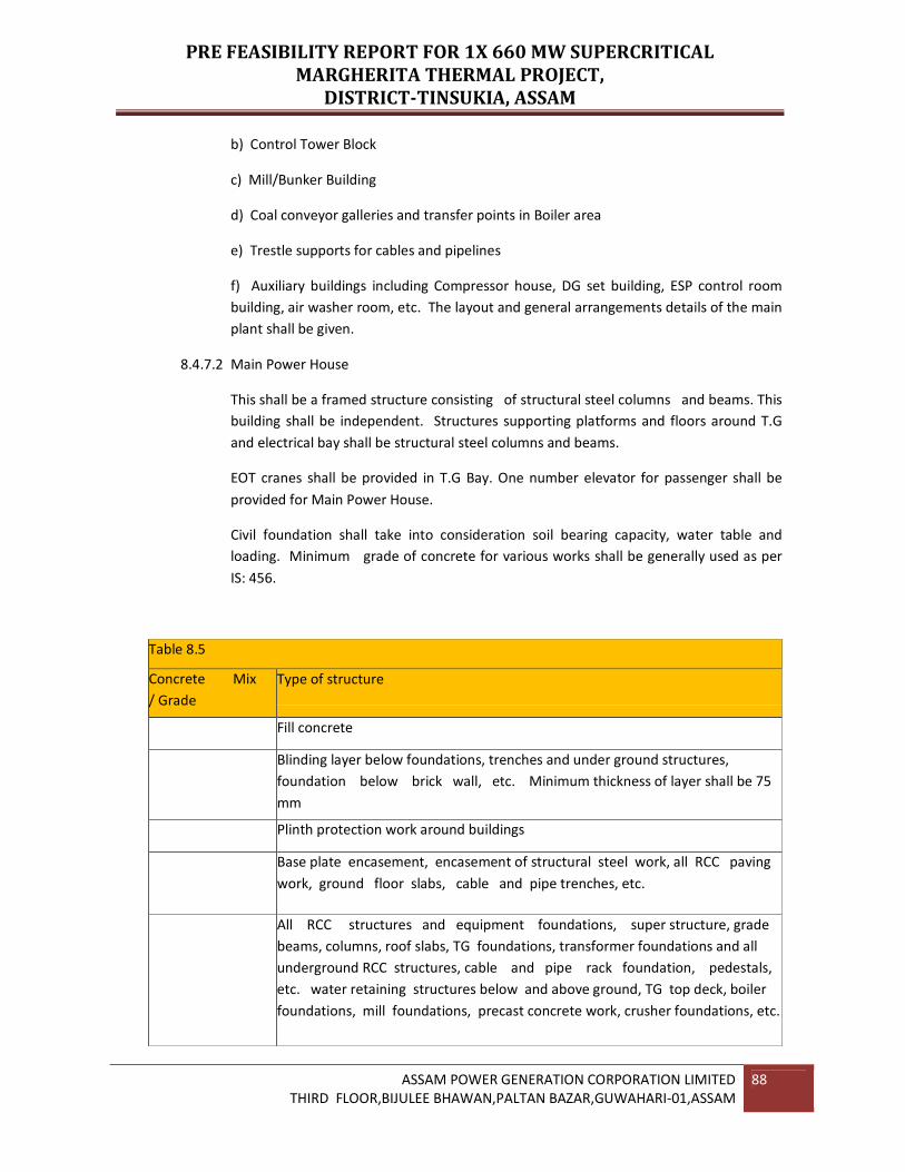
PRE FEASIBILITY REPORT FOR 1X 660 MW SUPERCRITICAL
MARGHERITA THERMAL PROJECT,
DISTRICT-TINSUKIA, ASSAM
ASSAM POWER GENERATION CORPORATION LIMITED
THIRD FLOOR,BIJULEE BHAWAN,PALTAN BAZAR,GUWAHARI-01,ASSAM
88
b) Control Tower Block
c) Mill/Bunker Building
d) Coal conveyor galleries and transfer points in Boiler area
e) Trestle supports for cables and pipelines
f) Auxiliary buildings including Compressor house, DG set building, ESP control room
building, air washer room, etc. The layout and general arrangements details of the main
plant shall be given.
8.4.7.2 Main Power House
This shall be a framed structure consisting of structural steel columns and beams. This
building shall be independent. Structures supporting platforms and floors around T.G
and electrical bay shall be structural steel columns and beams.
EOT cranes shall be provided in T.G Bay. One number elevator for passenger shall be
provided for Main Power House.
Civil foundation shall take into consideration soil bearing capacity, water table and
loading. Minimum grade of concrete for various works shall be generally used as per
IS: 456.
Table 8.5
Concrete Mix
/ Grade
Type of structure
Fill concrete
Blinding layer below foundations, trenches and under ground structures,
foundation below brick wall, etc. Minimum thickness of layer shall be 75
mm
Plinth protection work around buildings
Base plate encasement, encasement of structural steel work, all RCC paving
work, ground floor slabs, cable and pipe trenches, etc.
All RCC structures and equipment foundations, super structure, grade
beams, columns, roof slabs, TG foundations, transformer foundations and all
underground RCC structures, cable and pipe rack foundation, pedestals,
etc. water retaining structures below and above ground, TG top deck, boiler
foundations, mill foundations, precast concrete work, crusher foundations, etc.
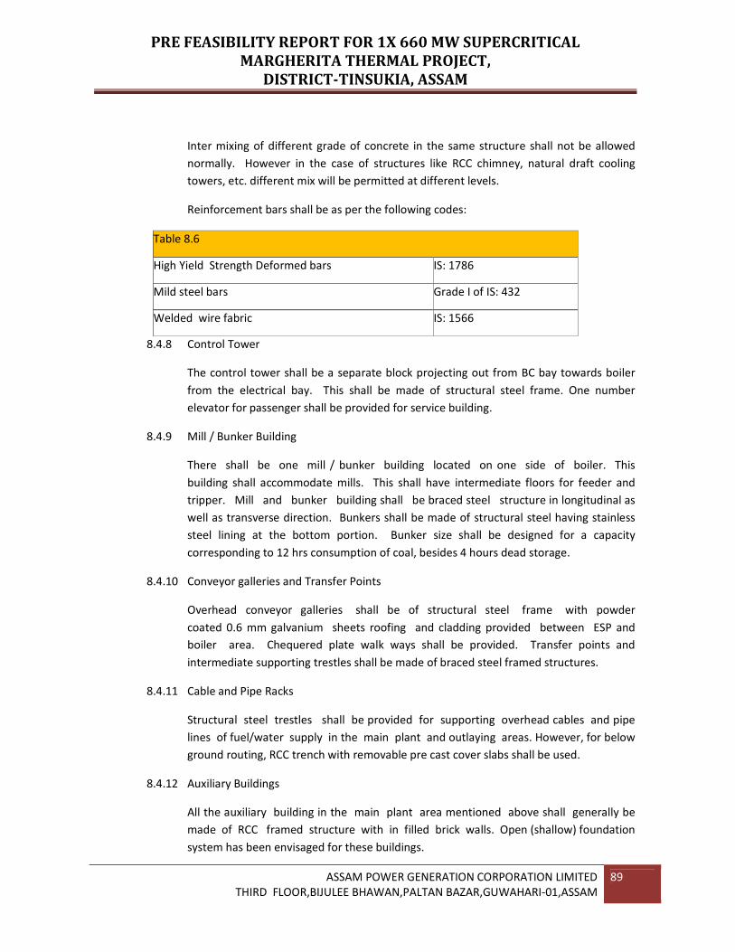
PRE FEASIBILITY REPORT FOR 1X 660 MW SUPERCRITICAL
MARGHERITA THERMAL PROJECT,
DISTRICT-TINSUKIA, ASSAM
ASSAM POWER GENERATION CORPORATION LIMITED
THIRD FLOOR,BIJULEE BHAWAN,PALTAN BAZAR,GUWAHARI-01,ASSAM
89
Inter mixing of different grade of concrete in the same structure shall not be allowed
normally. However in the case of structures like RCC chimney, natural draft cooling
towers, etc. different mix will be permitted at different levels.
Reinforcement bars shall be as per the following codes:
Table 8.6
High Yield Strength Deformed bars IS: 1786
Mild steel bars Grade I of IS: 432
Welded wire fabric IS: 1566
8.4.8 Control Tower
The control tower shall be a separate block projecting out from BC bay towards boiler
from the electrical bay. This shall be made of structural steel frame. One number
elevator for passenger shall be provided for service building.
8.4.9 Mill / Bunker Building
There shall be one mill / bunker building located on one side of boiler. This
building shall accommodate mills. This shall have intermediate floors for feeder and
tripper. Mill and bunker building shall be braced steel structure in longitudinal as
well as transverse direction. Bunkers shall be made of structural steel having stainless
steel lining at the bottom portion. Bunker size shall be designed for a capacity
corresponding to 12 hrs consumption of coal, besides 4 hours dead storage.
8.4.10 Conveyor galleries and Transfer Points
Overhead conveyor galleries shall be of structural steel frame with powder
coated 0.6 mm galvanium sheets roofing and cladding provided between ESP and
boiler area. Chequered plate walk ways shall be provided. Transfer points and
intermediate supporting trestles shall be made of braced steel framed structures.
8.4.11 Cable and Pipe Racks
Structural steel trestles shall be provided for supporting overhead cables and pipe
lines of fuel/water supply in the main plant and outlaying areas. However, for below
ground routing, RCC trench with removable pre cast cover slabs shall be used.
8.4.12 Auxiliary Buildings
All the auxiliary building in the main plant area mentioned above shall generally be
made of RCC framed structure with in filled brick walls. Open (shallow) foundation
system has been envisaged for these buildings.

PRE FEASIBILITY REPORT FOR 1X 660 MW SUPERCRITICAL
MARGHERITA THERMAL PROJECT,
DISTRICT-TINSUKIA, ASSAM
ASSAM POWER GENERATION CORPORATION LIMITED
THIRD FLOOR,BIJULEE BHAWAN,PALTAN BAZAR,GUWAHARI-01,ASSAM
90
8.4.13 Floors and Walls
Roof AB bay of main power-house shall be provided with cold formed troughed steel
sections used as covering cum permanent shuttering over which either foam
concrete or RCC slab would be placed. All other roofs and floors shall be made of RCC
slab.
External cladding of main plant building other than transfer points shall be of brick
masonry having minimum one brick thickness. All the partition walls shall also be of
brick masonry. Corrugated galvanized M.S. Sheet shall be provided for cladding of
transfer points. However internal partition in control tower shall consist of glazed
aluminium.
8.4.14 Architectural and Finishing Works
External and other finishes shall be decided based on good aesthetic and
architectural considerations. The operating floor of main power house shall be finished
with heavy duty concrete tiles (Carborundum tiles). Unit control rooms, control
equipment rooms and ESP control room shall have flexible PVC tile flooring. Computer
room shall have particle board false flooring. Acid resistant tiles shall be used in battery
room floor. Terrazzo flooring shall be provided for entrance area, staircase, entrance
lobby, office areas and toilets. All other floor areas shall generally be finished with
metallic hardener topping. Combination of resin bonded granular textured finish
(Vineratex) and sandtex matt paint shall be used for external finish. Inside wall of unit
control room shall be provided with white marble tiles. All main doors shall be made of
aluminium (glazed). All control rooms shall have doors windows and partitions
made of glazed aluminium. Ceiling shall be white washed and internal wall faces shall
receive distemper/acrylic emulsion paint. Steel structures shall be finished with
chemical resistant paint on account of marine environment. Unit control room shall
be provided with permanently colour coated lineal aluminium false ceiling. All air
conditioned areas shall be provided with pre-laminated particle board false ceiling.
Boiler area shall be provided with RCC paving with metallic hardener topping.
8.4.15 Chimney
A multi flue reinforced Concrete Chimney is preferred from environmental
consideration, inspection and maintenance advantages and construction ease. The
flue gas emission point shall be 275 Mts above the plant ground level. External
cage elevator (electric driven) will be provided for construction and maintenance. The
chimney windshield would be of RCC with slip form method of construction. The
chimney shaft will be of RCC with slip form construction on a RCC raft foundation. As
per statutory requirements, aircraft warning light and lighting electrodes etc., on the top
of the chimney would be provided.

PRE FEASIBILITY REPORT FOR 1X 660 MW SUPERCRITICAL
MARGHERITA THERMAL PROJECT,
DISTRICT-TINSUKIA, ASSAM
ASSAM POWER GENERATION CORPORATION LIMITED
THIRD FLOOR,BIJULEE BHAWAN,PALTAN BAZAR,GUWAHARI-01,ASSAM
91
Liner (flue) shall be constructed from structural steel and shall be hung from the liner
support platform near the Chimney top. The liner shall be provided with resin bonded
wool type thermal insulation.
The portion of the liner protecting above the Chimney roof shall be of stainless steel.
Intermediate internal platform shall be provided for enabling access to various
elevators of the stack and to provide lateral restraint to the steel liner.
The structural steel transition inlet ducting shall be bottom supported. This transition
ducting shall be suitably profiled from a rectangular shape at the chimney inlet to a
circular shape inside the chimney where it shall be connected to the suspended
circular steel liner through suitable (non-metallic) fluro elastometric fabric
expansion compensators. Transition ducting shall also be thermally insulated. Fabric
expansion compensators shall be installed after the transition ducts have been erected.
Internal platform shall be structural steel construction and shall be supported from the
wind shield. The floors/walkways shall be of chequered plate construction. The
chimney roof shall, however comprise of a reinforced concrete slab supported over a
grid of structural steel beams. The roof slab shall be protected by a layer of acid
resistant tiles. The grade level slab shall be of reinforced concrete with a metallic
hardener floor finish.
An internal structural steel staircase, supported from the shell wall, shall be
provided for full height of the stack. This shall provide access to all internal platforms
giving ample access to various elevations of the chimney. The stair treads shall be
fabricated from chequered plates.
The top external portion of the wind shield shall be coated with acid and heat
resisting paint in alternate bands of colors red and white to meet the aviation safety
requirements. The mini-shells and the top few meters of the internal surface of the
wind shield shall be painted for acid and heat protection with bituminous paint.
The other components of the chimney include a large roll-up door and a
personnel access door at grade level, doors at all platform levels, a personnel access
hatch in the roof slab, liner hatches, liner test ports, rain water drainage system, flue
liner drainage system, louvers with bird screens for ventilation openings, electrical
power supply, distribution boards, socket outlets, power and control cabling, raceway
system, stair and platform lighting, lightning protection and grounding system,
aviation obstruction lighting and communication system. Provisions shall be made for a
proven rack and pinion elevator or any other type of elevator. All mild steel
components shall be protected by a durable painting system.
Mild steel discrete strakes shall be provided, at the top (usually 1/3rd height) if found
necessary from design requirements. The super structure shall be supported on a
foundation system with piles.
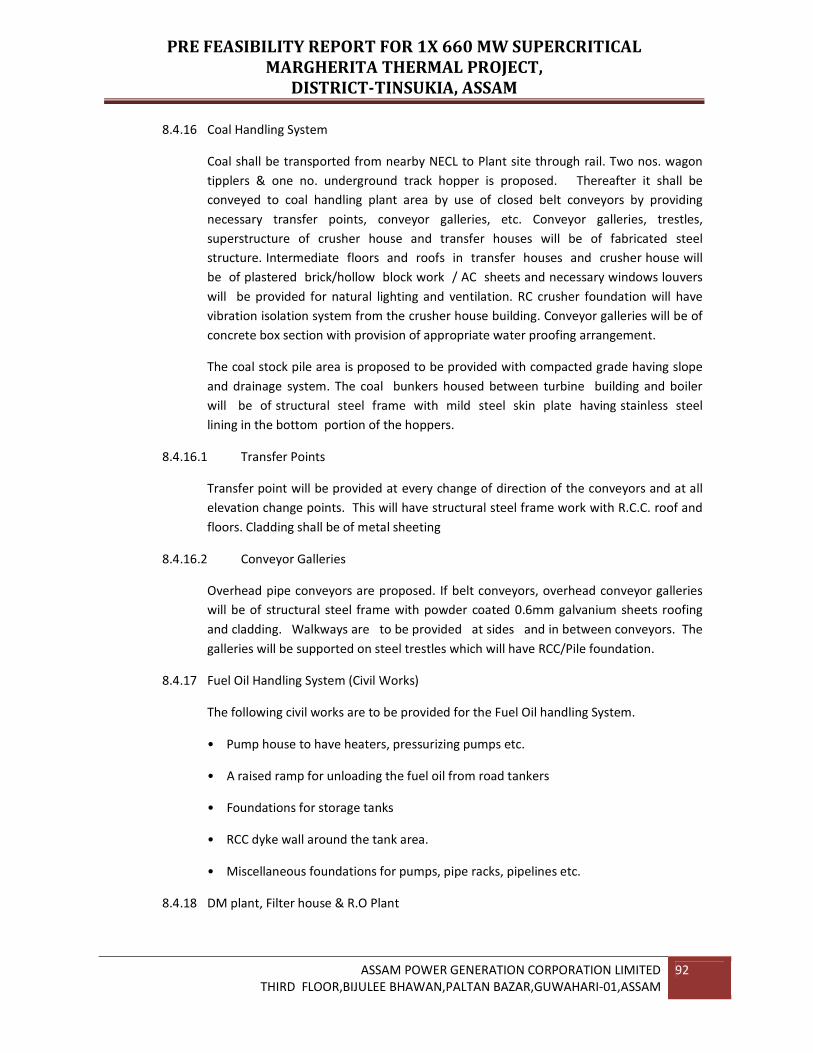
PRE FEASIBILITY REPORT FOR 1X 660 MW SUPERCRITICAL
MARGHERITA THERMAL PROJECT,
DISTRICT-TINSUKIA, ASSAM
ASSAM POWER GENERATION CORPORATION LIMITED
THIRD FLOOR,BIJULEE BHAWAN,PALTAN BAZAR,GUWAHARI-01,ASSAM
92
8.4.16 Coal Handling System
Coal shall be transported from nearby NECL to Plant site through rail. Two nos. wagon
tipplers & one no. underground track hopper is proposed. Thereafter it shall be
conveyed to coal handling plant area by use of closed belt conveyors by providing
necessary transfer points, conveyor galleries, etc. Conveyor galleries, trestles,
superstructure of crusher house and transfer houses will be of fabricated steel
structure. Intermediate floors and roofs in transfer houses and crusher house will
be of plastered brick/hollow block work / AC sheets and necessary windows louvers
will be provided for natural lighting and ventilation. RC crusher foundation will have
vibration isolation system from the crusher house building. Conveyor galleries will be of
concrete box section with provision of appropriate water proofing arrangement.
The coal stock pile area is proposed to be provided with compacted grade having slope
and drainage system. The coal bunkers housed between turbine building and boiler
will be of structural steel frame with mild steel skin plate having stainless steel
lining in the bottom portion of the hoppers.
8.4.16.1 Transfer Points
Transfer point will be provided at every change of direction of the conveyors and at all
elevation change points. This will have structural steel frame work with R.C.C. roof and
floors. Cladding shall be of metal sheeting
8.4.16.2 Conveyor Galleries
Overhead pipe conveyors are proposed. If belt conveyors, overhead conveyor galleries
will be of structural steel frame with powder coated 0.6mm galvanium sheets roofing
and cladding. Walkways are to be provided at sides and in between conveyors. The
galleries will be supported on steel trestles which will have RCC/Pile foundation.
8.4.17 Fuel Oil Handling System (Civil Works)
The following civil works are to be provided for the Fuel Oil handling System.
• Pump house to have heaters, pressurizing pumps etc.
• A raised ramp for unloading the fuel oil from road tankers
• Foundations for storage tanks
• RCC dyke wall around the tank area.
• Miscellaneous foundations for pumps, pipe racks, pipelines etc.
8.4.18 DM plant, Filter house & R.O Plant

PRE FEASIBILITY REPORT FOR 1X 660 MW SUPERCRITICAL
MARGHERITA THERMAL PROJECT,
DISTRICT-TINSUKIA, ASSAM
ASSAM POWER GENERATION CORPORATION LIMITED
THIRD FLOOR,BIJULEE BHAWAN,PALTAN BAZAR,GUWAHARI-01,ASSAM
93
Demineralization plant building shall be framed RCC Structure with in filled brick work.
The concrete shall be of M-20 grade for all super structural work. The adequate size of
the building shall be provided.
Underground RCC neutralization pit shall be constructed in two compartments with
concrete of grade M-25. Required size of neutralization pit shall be provided. The inside
face of pit shall be provided with acid/alkali resistant lining.
Condensate polishing unit, degasser and acid storage tanks being outdoor type
installations. Only raft foundation along with dyke wall is envisaged. This shall be of
RCC with concrete of grade M25. Adequate size of the building shall be provided.
The foundation for 1 No.of D.M tank shall be of RCC of grade M-25.The diameter of ring
beam for supporting the tank shall be about 13.4 m.
A filter house cum filter water pump house building shall be constructed to house 2
gravity filters. The building shall be of RCC framed structure of grade m-25.Reverse
Osmosis building shall be RCC framed structure of concrete of grade M20. The
adequate size of the building shall be provided.
The foundation for 2 Nos of Reverse Osmosis water tanks shall be constructed of RCC of
grade M-25. The dia. of the ring beam shall be about 13 m.
8.4.19 Cooling Water System
Buridihing River Water is proposed to be used for the CW system, protection of concrete
and steel shall be provided. This shall include use of dense and durable concrete (M-25)
with plasticizer cum water proofing agent, use of sulphate resistant cement, coating of
reinforcement etc.
All steel pipes used in CW system will be gunnited with a minimum thickness of 50 mm.
CW ducts would be lined with concrete on both inside and outside surface. Minimum
thickness of outside concrete layer shall be 75 mm. Alternately GRP pipes and
ducts can be used in CW system.
8.4.20 Raw Water System
A RCC raw water reservoir shall be provided with adequate capacity for storing sweet
water requirements. One number raw water pump house shall be provided. Pump
house shall be provided to the potable water reservoir for potable water supply.
Sub-structure of the pump houses shall be of RCC while super structure shall be of
steel with in filled brick panel walls and RCC cast-in- situ roofing over permanent
metal decking.
In addition to the above one RCC fire water reservoir of 500 cu.m capacity shall be
provided in plant area for fire water storage. One no. fire water pump house shall be
provided adjacent to the reservoir which will house fire water pumps. Sub-structure

PRE FEASIBILITY REPORT FOR 1X 660 MW SUPERCRITICAL
MARGHERITA THERMAL PROJECT,
DISTRICT-TINSUKIA, ASSAM
ASSAM POWER GENERATION CORPORATION LIMITED
THIRD FLOOR,BIJULEE BHAWAN,PALTAN BAZAR,GUWAHARI-01,ASSAM
94
and super structure of the pump house shall be similar to that of the above referred
pump house.
8.4.21 Switchyard
Switchyard structures including equipment supports will be of galvanized steel. The
foundations will be RCC spread footing. Cable trench, pits etc. will be of RCC with pre-
cast RCC covers. Peripheral and internal roads will be provided for access during
equipment maintenance. The entire area will be enclosed with suitable safety fencing
and control gate.
8.4.22 Ancillary Buildings
Ancillary building such as service building, electrical switchgear room building etc. shall
be provided. These buildings shall generally be constructed of RCC frame work with
infilled brickwork. Service building shall be separated from Main TG building, at least by
10 to 20 feet with partition wall to avoid noise.
8.4.23 Rain Water harvesting Scheme
Suitable rain water harvesting scheme acceptable to National Ground Water
Authority shall be provided for main plant building and other major building.

PRE FEASIBILITY REPORT FOR 1X 660 MW SUPERCRITICAL
MARGHERITA THERMAL PROJECT,
DISTRICT-TINSUKIA, ASSAM
ASSAM POWER GENERATION CORPORATION LIMITED
THIRD FLOOR,BIJULEE BHAWAN,PALTAN BAZAR,GUWAHARI-01,ASSAM
95
SECTION - 9
ENVIRONMENTAL CONSIDERATIONS
9.1.0 The proposed power plant of 1 x 660 MW will be coal fired. A coal fired thermal power
station can contribute to environmental pollution in the following manner:
a) Atmospheric pollution through particulate and gaseous emissions
b) Thermal pollution of the surroundings
c) Discharge of solid and liquid wastes
d) Noise pollution
Type & Source of Pollution
Table 9.1
SL no Type Source of Pollution
1 Air pollution • Particulate Matter in flue gas
• Sulphurdioxide in flue gas
• Nitrogenoxides in flue gas
• Coal dust particles during storage/handling
• Dust in the ash disposal area
2 Water &Sewage
pollution
Effluent from ash disposal area
Effluent from water treatment plant(WTP)
Steam generator blow down
Cooling tower blow down
Plant drain
• Domestic Sewage
• Effluent from coal pile area runoff
3 Noise Pollution Steam turbine generator
• Other rotating equipment
• Combustion induced noises
• Flow induced noises
• Steam safety valve
4 Solid Waste
Ash Management

PRE FEASIBILITY REPORT FOR 1X 660 MW SUPERCRITICAL
MARGHERITA THERMAL PROJECT,
DISTRICT-TINSUKIA, ASSAM
ASSAM POWER GENERATION CORPORATION LIMITED
THIRD FLOOR,BIJULEE BHAWAN,PALTAN BAZAR,GUWAHARI-01,ASSAM
96
9.2.0 ENVIRONMENTAL PROTECTION AND POLLUTION ABATEMENT
9.2.1 GENERAL
Environmental protection and the control of solid, liquid and gaseous effluents or
emissions are key elements in the design of all steam power generating systems. The
emissions from thermal power plants are regulated by State and Central Governments.
Minimizing aqueous discharges and safely disposing of solid by-products are key
issues for power projects.
Atmospheric emissions arise primarily from the by-products of the combustion process
SO2, NOx, particulate fly ash, volatile organic compounds (VOC) and some trace
quantities of other materials and are exhausted from the stack. Another source of air
emissions is the cooling tower and the associated thermal rise plume, which contains
heat and some trace materials along with the water vapour.
Aqueous discharges arise from following sources: cooling tower blow down, boiler
chemical cleaning solutions, gas side water washing waste solutions, as well as a variety
of low volume wastes including ion exchange regeneration solutions from the Water
treatment Plants, boiler blow down, sewerage system discharges from buildings and
plant floor drains.
9.2.2 PARTICULATE MATTER AND GASES
The elements polluting the air that are discharged from the proposed PP are:
• Dust particulate from fly ash in flue gas
• Nitrogen oxide in flue gas
• Sulphur-di-oxide in the flue gas
Electrostatic precipitators are proposed for the steam generator, to contain the dust
emission from plant to a level less than 25 Mg/Ncum. The height of the stack for the
boiler, which disburses the pollutants, has been fixed at 275 meters. This is based on
maximum sulphur content in coal of 1.5% to 4% and average GCV of 5500 kcal/kg.
Due to high content of sulphur in NEC coal especially Margherita coal FGD technology
has be considered for implementation to extract the Sulphur from flue gases.
9.2.2.1 FLY ASH AND FURNACE BOTTOM ASH
Fly ash collected from the ESP hoppers and the air heater hoppers and the ash collected
from the furnace bottom hoppers will be collected by a pneumatic or vacuum ash
handling system and stored in day silos.
PRE FEASIBILITY REPORT FOR 1X 660 MW SUPERCRITICAL
MARGHERITA THERMAL PROJECT,
DISTRICT-TINSUKIA, ASSAM
ASSAM POWER GENERATION CORPORATION LIMITED
THIRD FLOOR,BIJULEE BHAWAN,PALTAN BAZAR,GUWAHARI-01,ASSAM
97
9.2.3 WATER POLLUTION
9.2.3.1 EFFLUENT FROM WATER TREATMENT PLANT
Hydrochloric acid and sodium hydroxide will be used as regenerants in the proposed
strong acid cation exchanger, strong base anion exchanger and mixed bed polisher of
the water treatment plant. However, the quantity of these chemicals used will be low
and the frequency very less due to the fact that the regeneration is only for the Mixed
Bed. Since the water treatment plant will be based on the RO principle, the
requirement of the chemicals will not be same as that of a conventional
demineralisation plant. The acid and alkali effluents generated during the
regeneration process of the ion-exchangers would be drained into an epoxy lined
underground neutralizing pit. Generally, these effluents are self neutralizing. However
provisions will be made such that the effluents will be neutralised by addition of
either acid or alkali to achieve the required pH of about 7.0. The effluent will then
be pumped into the effluent treatment ponds.
Apart from the regenerates discharged to the neutralising pit, the RO discharges the
reject water, which has higher TDS. This also will be let into the neutralising pit
and the RO discharge will be diluted with the blow down from the cooling tower
and the other discharges before letting the same out to the effluent treatment
plant.
9.2.3.2 STEAM GENERATOR BLOW DOWN
The salient characteristics of blow down water from the point of view of pollution are
the pH and temperature of water since suspended solids are negligible. The pH would
be in the range of 9.8 to 10 and the temperature of blow down water will be 100 ºC.
9.2.3.3 WASTE WATER TREATMENT
Wastewater treatment for the plant will be based on discharges of the various
wastewaters to ponds for clarification and filtration. Oily water will be treated
separately to remove Oil / Grease before discharge into effluent ponds. The oily water
collection in the plant is basically due to floor cleaning, leaky oil filters, etc.
Clarification is used to settle out large suspended particles and condition smaller
colloidal particles to make them settle. A reservoir tank is used to allow larger particles
to settle in a matter of hours. The finer particles overflow and are made to settle more
quickly by the addition of chemical agents, coagulants and polymers that cause
agglomeration to sizes large enough to settle out of suspension.
Filtration will be made to a porous barrier across flowing liquid to remove suspended
materials. Filtration can be used to supplement clarification and permits reducing
suspended solids to the parts per billion levels.

PRE FEASIBILITY REPORT FOR 1X 660 MW SUPERCRITICAL
MARGHERITA THERMAL PROJECT,
DISTRICT-TINSUKIA, ASSAM
ASSAM POWER GENERATION CORPORATION LIMITED
THIRD FLOOR,BIJULEE BHAWAN,PALTAN BAZAR,GUWAHARI-01,ASSAM
98
As required and with approvals from appropriate regulating bodies, combining various
plant streams to provide a neutral pH product controls final waste stream pH. Where
needed, acid or alkali addition will be used to achieve the final pH.
9.2.4 THERMAL POLLUTION
Natural Draft cooling water system has been proposed. This eliminates the letting out of
high temperature water into the canals and prevents thermal pollution. Blow down
form the cooling tower will be trenched out and ultimately conveyed to the effluent
ponds. Hence there is no separate pollution on account of blow down form cooling
water system.
9.2.5 NOISE POLLUTION
The rotating equipment in the PP will be designed to operate with a total noise level of
not exceeding 85 to 90 db (A) as per the requirement of Occupational Safety and Health
Administration (OSHA) Standards. The rotating equipments are provided with silencers
wherever required to meet the noise pollution. As per OSHA, protection form noise is
required when sound levels exceed those given in the following table.
9.2.5.1 PERMISSIBLE NOISE LEVELS
Table 9.2
Exposure Duration / Day Sound Level db(A)
8 90
6 92
4 95
3 97
2 100
1 102
9.2.6 MONITORING OF EFFLUENTS
The characteristics of the effluents from the proposed power plant will be maintained so
as to meet the requirements of State Pollution Control Board and the minimum
standards and thereby assure that the air quality is maintained within the prescribed
within the prescribed levels.
The following will be monitored form the stack emissions.
• Suspended Particulate Matter
• Sulphur-Di-Oxide
PRE FEASIBILITY REPORT FOR 1X 660 MW SUPERCRITICAL
MARGHERITA THERMAL PROJECT,
DISTRICT-TINSUKIA, ASSAM
ASSAM POWER GENERATION CORPORATION LIMITED
THIRD FLOOR,BIJULEE BHAWAN,PALTAN BAZAR,GUWAHARI-01,ASSAM
99
The Laboratory attached to the PP will be equipped with the necessary instruments for
carrying out air quality monitoring. It is also proposed to monitor the particulate
emission at the stack to keep a continuous check on the performance of the ESP.
Adequate sampling openings will be provided in the stack.
9.2.7 IMPACT OF THE POLLUTION ON THE ENVIRONMENT
As all the necessary pollution control measures to maintain the emission levels of dust
and SO2 are taken and other effluents will be treated in the effluent treatment
plant, there will be no adverse impact on either the air or water quality in around
the PP site on account of the installation of the plant.
Other provisions for pollution on line monitoring and control to ensure compliance
9.2.8 RESETTLEMENT & REHABILITATION
Government of India has recently formulated the National Rehabilitation and
Resettlement Policy 2007which has wider social implication.
The major objectives of the Policy are as follows:
• To minimize displacement and to promote, as far as possible, non-displacing or
least-displacing alternatives;
• To ensure adequate rehabilitation package and expeditious implementation of
rehabilitation with active people’s participation
• To protect the rights of weaker sections, especially members of SCs and STs.
• To provide better standard of living and to ensure sustainable income to affected
families
• To integrate rehabilitation concerns into the development planning and
implementation process
• To facilitate harmonious relationship between the body which acquires land and the
affected families through mutual cooperation.
The site of the proposed power plant is highly undulated with ridges and valleys covered
with tea plantation & forest. For cultivated land requires R & R, this will not cause
any impact for the project implementation with the requirements of the State
Environment Conservation Board will be made.
9.2.9 Green Belt Development:
With a view to attenuate air pollutants, fugitive dust, to absorb noise and to care of
uptake of water pollutants if any, it is recommended to develop a greenbelt all around
the boundary and at several locations within the proposed power plant premises.

PRE FEASIBILITY REPORT FOR 1X 660 MW SUPERCRITICAL
MARGHERITA THERMAL PROJECT,
DISTRICT-TINSUKIA, ASSAM
ASSAM POWER GENERATION CORPORATION LIMITED
THIRD FLOOR,BIJULEE BHAWAN,PALTAN BAZAR,GUWAHARI-01,ASSAM
100
Green belt shall be developed along the boundary of the project site. Since the site area
of the proposed power plant consists of consists of hillocks, hills and valleys, much
excavation will be required for grading the land at different levels. Green belt will
prevent the soil erosion and improve the soil stabilization.
The thick vegetation in the plant premises will also attenuate continuous noise.
Adequate green belt would be developed in and around the project area and the ash
disposal area satisfying the requirement of state as well as Central Pollution Control
Board (CPCB). Plantation near coal stacks and the ash disposal area to arrest fugitive
dust are also proposed. A separate study to select appropriate type of trees and plants
suitable for this region would be taken up in the detail engineering stage. These green
belts, apart from stopping soil erosion, arresting air-borne dust particles and acting as
noise- barrier, would help in improvement of ecology and aesthetics of the area.

PRE FEASIBILITY REPORT FOR 1X 660 MW SUPERCRITICAL
MARGHERITA THERMAL PROJECT,
DISTRICT-TINSUKIA, ASSAM
ASSAM POWER GENERATION CORPORATION LIMITED
THIRD FLOOR,BIJULEE BHAWAN,PALTAN BAZAR,GUWAHARI-01,ASSAM
101
SECTION – 10
EXECUTION AND PROJECT MANAGEMENT
10.1.0 CONSTRUCTION FACILITIES REQUIREMENT
The 1x 660 MW power stations is proposed to be located near Saliki Village at a distance
around 2 km south-west of NH-38 in Margherita sub-divisional town of Tinsukia District
of Assam. Adequate construction facilities such as office, stores, sheds etc. will be
provided for the successful & timely implementation of the plant.
10.1.1 CONSTRUCTION POWER
The estimated construction power for construction of the plant is about 2000 KVA. The
required construction power supply will be made available from existing
substation at of APDCL. A DG set of adequate size will also be provided as standby
arrangement for power supply at site for the construction phase of the power project.
10.1.2 TRANSPORT LIMITATIONS
Though the site of the proposed thermal power plant can be accessed by road, the
connecting road between the site and NH-38 is a kachha road. This road is not suitable
for heavy vehicles. The kachha road from NH-38 to the proposed thermal power plant
site needs to be developed during project stage for heavy vehicle movement. The site is
connected with DibrugarhTown by NH-37 via Tinsukia up to Makum and NH-38 from
Makum upto Lekkhapani. Further this highway merges into NH-153 which goes upto
Indian Border with Myanmar. The logistics will be further reviewed during detail
engineering in line with the requirement of original equipment manufacturer.
10.1.3 WATER REQUIRED DURING CONSTRUCTION
The water required during construction is estimated at 200 Cu.m/day and will be met
from suitable ground water source till water system is established alternatively.
Raw materials for the construction of the proposed station such as stone aggregate,
conforming to IS-383 and sand free of silt meeting the requirements of IS-650 will be
obtained from nearby area.
Cement will be available from Cement Plants in the State. Steel will be made available
from the nearest steel stockyard.
10.2.0 Project Implementation Schedule
• The zero date has been taken as the day the main equipment packages viz. the
steam generator, TG & their auxiliaries are ordered.

PRE FEASIBILITY REPORT FOR 1X 660 MW SUPERCRITICAL
MARGHERITA THERMAL PROJECT,
DISTRICT-TINSUKIA, ASSAM
ASSAM POWER GENERATION CORPORATION LIMITED
THIRD FLOOR,BIJULEE BHAWAN,PALTAN BAZAR,GUWAHARI-01,ASSAM
102
• The Unit will be scheduled to 42 Months from the Date of Order
• The Erection, Testing & Commissioning of the units will be undertaken by a team of
responsible, competent and efficient personnel to ensure that:
a) The units will be made ready for operation in the shortest possible time and in no
case should the scheduled time is exceeded.
b) To reduce interest charges and unnecessarily large inventories will not be built up.
c) The plant once installed will have a high reliability and availability.
d) The timely design & construction of the main plant building housing the TG is
important and will not be delayed on any account.
10.3.0 Project Manpower Requirements:
The recent development automation with advanced technology, the manpower
would be quite limited. The estimated manpower requirement is indicated as below:
Man Power
Managerial / Executive (senior level) : 30
Engineers / Supervisors : 320
Operators : 120
Skilled Attendants : 80
Semi-skilled Attendants : 50
Total : 600
10.3.1 Basis of Manpower Estimates
In arriving at the manpower estimates, the following assumptions have made: The
Manpower estimate has prepared with reference to the process and facilities Envisaged
in the different shops. Whenever direct manning is involved the various positions have
been identified on the basis of the layout, technology, equipment location and job
affinity. Where a crew is required for a particular operation, the crew size has been
determined taking into account the proposed facility and functions involved.
Keeping in view the extent of automation and computerization as envisaged in the
project, Supervisors & skilled staff is not required much as presently deployed
in old conventional plants. However, the proposed deployment of manpower, more
or less matches with the standard norms which provide 0.4 men per MW for large

PRE FEASIBILITY REPORT FOR 1X 660 MW SUPERCRITICAL
MARGHERITA THERMAL PROJECT,
DISTRICT-TINSUKIA, ASSAM
ASSAM POWER GENERATION CORPORATION LIMITED
THIRD FLOOR,BIJULEE BHAWAN,PALTAN BAZAR,GUWAHARI-01,ASSAM
103
Power Plant. It is assumed that the work force will, therefore, have the requisite skills to
operate the equipment as well as make the minor repairs, and to set and adjust the
equipment handled by them. They will also be responsible for proper up keeping of the
equipment and the surrounding workplace. They will assist the maintenance personnel
in maintaining the plant & equipment.
Provision of 20% of the manpower required per weekdays has been made to cover the
weekly off, holiday, leave for departments /sections working seven- day week.
For departments /sections working 6 day week, a provision of 10% additional manpower
has been made to cover holidays and leave.
Major maintenance of plant & equipment and Capital repair jobs will be outsourced.
Only routine scheduled maintenance, running repairs and conditioning monitoring will
be done departmentally. Also, operating staff of any equipment under maintenance will
participate in maintenance along with the maintenance personnel.
10.3.2 Training
Depending on the level and experience of O & M staff, training programs will be
designed and implemented by equipment manufacturer in association with O & M
contractor and the owner. The covered includes the following:
• The Training at manufacturer’s works
• Training at operating plants in India and abroad where similar equipment are in
operation.
• Maintenance training.
• Simulator training
• Skill up-gradation
• Workshops
10.3.3 Training Policy
An appropriate training policy would be adopted at the outset aiming to fulfill the main
objectives of improving the organization efficiency & effectiveness as a whole and
also to maintain a high technological status and develop an understanding of
the importance of co-operation & teamwork.

PRE FEASIBILITY REPORT FOR 1X 660 MW SUPERCRITICAL
MARGHERITA THERMAL PROJECT,
DISTRICT-TINSUKIA, ASSAM
ASSAM POWER GENERATION CORPORATION LIMITED
THIRD FLOOR,BIJULEE BHAWAN,PALTAN BAZAR,GUWAHARI-01,ASSAM
104
SECTION – 11
CLEAN DEVELOPMENT MECHANISM (CDM)
Clean Development Mechanism
The U.N. Framework Convention on Climate Change (UNFCCC) was adopted in June
1992 at the Earth Summit in Rio de Janeiro and the objective of the convention is
to achieve stabilization of greenhouse gas concentrations in the atmosphere at a level
that would prevent dangerous anthropogenic interference with the climate system.
The adjunct to the Convention, the Kyoto protocol, was hammered out in December
1997, setting individual targets for developed countries to reduce yearly
emissions of Green House Gases (GHGs) to a minimum of 5 percent below their
1990 levels in the first commitment period,
2008-2012. India has ratified the Kyoto Protocol in 2002.
The Clean Development Mechanism (CDM), one of the flexible mechanisms under the
Kyoto Protocol encourages development of Green house gas emission reduction
projects in developing countries like India for achieving sustainable development
and also earn carbon credits. The amount of carbon emission saved by such project is
required to be certified by the CDM Executive Board. The certificate specifying
carbon reduction in tones can be sold to developed countries which are signatories
to the protocol. One tone of carbon di-oxide reduced through Clean Development
Mechanism project in a developing country when certified by the CDM Executive Board
becomes a tradable CER (Certified Emission Reduction).
To get a project registered under CDM, it has to run through an approval
procedure, including the host country approval & validation, administered by the
UNFCCC. The Ministry of Environment and Forests (MoEF), GoI is the Designated
National Authority (DNA) in India for according hosts country approval.
APGCL intends to construct a new supercritical coal fired power project of capacity 1 X
660 MW MTTP with CDM intent, at Tinsukia district. Adopting Supercritical technology
results in enhanced plant efficiency resulting in reduced coal

PRE FEASIBILITY REPORT FOR 1X 660 MW SUPERCRITICAL
MARGHERITA THERMAL PROJECT,
DISTRICT-TINSUKIA, ASSAM
ASSAM POWER GENERATION CORPORATION LIMITED
THIRD FLOOR,BIJULEE BHAWAN,PALTAN BAZAR,GUWAHARI-01,ASSAM
105
SECTION – 12
PROJECT COST ESTIMATE
PROJECT COST ESTIMATE
12.1.1 Project Cost:
The estimated project cost has been worked out on the following basis and assumptions:
• The project cost has been estimated based on the recently decided EPC tender of TANGEDCO
for 660 MW (Super critical) Ennore thermal power station expansion project with a project cost of
3960 Crores ie Rs. 6.00 Crores per MW. Another 10% is added as it is a green field project.
• Fuel: Assam Coal is considered to be main fuel. The calorific value as coal is taken as 5500
kcal/kg . HFO / HSD shall be supporting and startup fuel.
• Electrical System: 400 kV switchyard for evacuation of power has been considered in
the present cost estimate. Cost of transmission line has not been considered in the project cost.
• The project cost is inclusive of all taxes and duties.
• The Total Project cost is as below:
Total project cost: Rs. 4383.98 crores
Interest during construction : Rs. 763.54 crores
Total project Cost with IDC & contingency: Rs. 5278.20 crores
Total Project cost per MW : 8.00 crores
12.1.2 Financing Structure and Interest during Construction:
• It is proposed to finance the project through debt – equity ratio of 70:30.
Project Cost : 4383.98 Rs. Crores
Debt(%) : 70 %
Debt (including IDC) : 3607.52 Rs. Crores
Equity(%) : 30 %

PRE FEASIBILITY REPORT FOR 1X 660 MW SUPERCRITICAL
MARGHERITA THERMAL PROJECT,
DISTRICT-TINSUKIA, ASSAM
ASSAM POWER GENERATION CORPORATION LIMITED
THIRD FLOOR,BIJULEE BHAWAN,PALTAN BAZAR,GUWAHARI-01,ASSAM
106
Equity : 1540.00 Rs. Crores
Project Cost including IDC & Contingency :
:
5278.20 Rs. Crores
Rate of interest : 12.5 %
• Time Schedule:
Commissioning of Unit – 1 (660 MW) :42 months from zero date
12.1.3 Estimation of Cost of Generation
The main objective is to estimate and analyze the capital cost of the project so as to be in a
position to estimate the Cost of Generation.
The major assumptions are as follows:
i) Debt Equity Ratio : 70:30
ii) The Construction period for 2 X 660 MW : 42 months
iii) Interest on term loan has been considered as 12.5 % with 15 years of Repayment period after
complete commissioning of the Plant.
iv) RoE is calculated on pre-tax basis at the base rate of 15.5%.
v) Working capital has been estimated based as follows:
a) Fuel Cost: 1.0 month
b) O&M Cost: 1.0 month
c) Margin Money: 10%
d) Rate of Interest: 12.5 %
e) Maintenance spares: 1% of the cost escalated @ 6% per year
vi) Auxiliary power consumption of the plant is 6% as per CERC guide line.
vii) Plant availability factor: 85% as per CERC guide line.
viii) O&M expenses have been considered as Rs. 16 lakh/MW with 5% escalation per year. )
ix) The plant gross heat rate has been considered as 2057 Kcal/Kwh as per
x) Depreciation has been considered at an average rate of 4.67% per year based on equipment-
wise rates specified as per CERC guidelines.

PRE FEASIBILITY REPORT FOR 1X 660 MW SUPERCRITICAL
MARGHERITA THERMAL PROJECT,
DISTRICT-TINSUKIA, ASSAM
ASSAM POWER GENERATION CORPORATION LIMITED
THIRD FLOOR,BIJULEE BHAWAN,PALTAN BAZAR,GUWAHARI-01,ASSAM
107
xi) The calorific value of coal has been considered as 5500 Kcal/kg.
xii) The cost of coal has been considered as Rs.4665 / MT and escalated @5% per year thereafter.
The cost of support fuel oil is considered as Rs.50.000/- per KL.
xiii) The oil consumption considered as @ 2 ml/KWh for the ml/KWh from 2nd year onwards.
xiv) The annual plant load factor (PLF) has been taken as 85% once the system has stabilized after
commissioning. (However, the plant loading most of the time will be 100%).
Based on the above assumptions, the first year tariff and the Levellized Tariff cost is given below:
Cost of generation @ 85% PLF on 1st year : Rs.3.401 / Unit
Levellised cost of generation @ 85% PLF : Rs. 3.220 / Unit
a) Useful life of the Thermal power station = 25 years
b) Depreciation Rate for first 15 years = 4.67%
c) Depreciation rate for remaining life = 2%

PRE FEASIBILITY REPORT FOR 1X 660 MW SUPER
MARGHERITA THERMAL PROJECT,
DISTRICT
THIRD FLOOR,BIJULEE BHAWAN,PALTAN BAZAR,GUWAHARI
13.1.0 Advantages of supercritical technology
Supercritical technology delivers the most economical in i
operating flexibility, achieve fuel cost savings, and reduce all emissions for each kWh
of electricity generated, including CO2.
• Higher plant efficiency
• Less Fuel Consumption
• Less Infrastructure Investment for
• Less Emission (CO2, SOx, NOx, Dust/Ash)
• Less Auxiliary Power Consumption
• Less Water Consumption (No
boiler.)
• Lower operating costs
• Greater operating flexibility
13.1.1 Elevated Steam Conditions
As the steam conditions become
date, even 600/600 degree
are 600 degree C) is already in o
LITY REPORT FOR 1X 660 MW SUPERCRITICAL
GHERITA THERMAL PROJECT,
DISTRICT-TINSUKIA, ASSAM
ASSAM POWER GENERATION CORPORATION LIMITED
THIRD FLOOR,BIJULEE BHAWAN,PALTAN BAZAR,GUWAHARI-01,ASSAM
SECTION – 13
CONCLUSION
Advantages of supercritical technology
Supercritical technology delivers the most economical in improve efficiency and
operating flexibility, achieve fuel cost savings, and reduce all emissions for each kWh
of electricity generated, including CO2.
plant efficiency
• Less Fuel Consumption
• Less Infrastructure Investment for Fuel Transport / Storage and Ash Disposal
• Less Emission (CO2, SOx, NOx, Dust/Ash)
• Less Auxiliary Power Consumption
Less Water Consumption (No need of continuous blows down in case of once
operating costs
operating flexibility
Elevated Steam Conditions
conditions become higher, plant heat consumption becomes
600 degree C (both superheater outlet and reheater outlet
are 600 degree C) is already in operation outside India.
CRITICAL
GHERITA THERMAL PROJECT,
ASSAM POWER GENERATION CORPORATION LIMITED
01,ASSAM
108
mprove efficiency and
operating flexibility, achieve fuel cost savings, and reduce all emissions for each kWh
Storage and Ash Disposal
down in case of once- through
consumption becomes less. To this
reheater outlet temperature

PRE FEASIBILITY REPORT FOR 1X 660 MW SUPER
MARGHERITA THERMAL PROJECT,
DISTRICT
THIRD FLOOR,BIJULEE BHAWAN,PALTAN BAZAR,GUWAHARI
Comparison of Typical Operation Modes
By adopting sliding pressure operation (more precisely, combined operation of
and sliding pressure operation), plant efficiency becomes higher at partial load range.
• Higher HP turbine internal efficiency.
• Less BFP power consumption.
• Higher reheat steam temperature at partial load.
13.1.2 Plant Availability:
The plant availability
13.1.3 CDM Benefits
Sub Critical Boilers (500 MW sets) involves
super heat / reheat temperature 5400C/5400C and super critical boilers would be
designed with pressure of 257 ata and above and super heat/reheat temperature of
5680C / 5920C and even above due to t
Normally sub critical units having the Plant heat rate around 2300
super critical units having the plant heat rate are about 2100 Kcal / Kwh. By adopting
Supercritical technology we have a
fuel consumption and less CO2 generation. This project can generate tradable carbon
credits under CDM thus
Table 13.1
Capacity MW
Baseline emission factor
Reduction in tonnes CO2 Emission for 1st
year
LITY REPORT FOR 1X 660 MW SUPERCRITICAL
GHERITA THERMAL PROJECT,
DISTRICT-TINSUKIA, ASSAM
ASSAM POWER GENERATION CORPORATION LIMITED
THIRD FLOOR,BIJULEE BHAWAN,PALTAN BAZAR,GUWAHARI-01,ASSAM
Comparison of Typical Operation Modes
sliding pressure operation (more precisely, combined operation of
and sliding pressure operation), plant efficiency becomes higher at partial load range.
• Higher HP turbine internal efficiency.
consumption.
• Higher reheat steam temperature at partial load.
The plant availability is more than 90 %.
Sub Critical Boilers (500 MW sets) involves steam pressure of 170 bar and below and
super heat / reheat temperature 5400C/5400C and super critical boilers would be
designed with pressure of 257 ata and above and super heat/reheat temperature of
5680C / 5920C and even above due to the invention of New materials.
Normally sub critical units having the Plant heat rate around 2300-2400 Kcal / Kwh and
super critical units having the plant heat rate are about 2100 Kcal / Kwh. By adopting
Supercritical technology we have able to achieve 200 Kcal / Kwh which leads to less
fuel consumption and less CO2 generation. This project can generate tradable carbon
CDM thus improving the financial viability of the project.
1 x 660 MW
Baseline emission factor 0.941 tCO2/MWh
Reduction in tonnes CO2 Emission for 1st 2395671.88
CRITICAL
GHERITA THERMAL PROJECT,
ASSAM POWER GENERATION CORPORATION LIMITED
01,ASSAM
109
sliding pressure operation (more precisely, combined operation of constant
and sliding pressure operation), plant efficiency becomes higher at partial load range.
steam pressure of 170 bar and below and
super heat / reheat temperature 5400C/5400C and super critical boilers would be
designed with pressure of 257 ata and above and super heat/reheat temperature of
he invention of New materials.
2400 Kcal / Kwh and
super critical units having the plant heat rate are about 2100 Kcal / Kwh. By adopting
ble to achieve 200 Kcal / Kwh which leads to less
fuel consumption and less CO2 generation. This project can generate tradable carbon

PRE FEASIBILITY REPORT FOR 1X 660 MW SUPERCRITICAL
MARGHERITA THERMAL PROJECT,
DISTRICT-TINSUKIA, ASSAM
ASSAM POWER GENERATION CORPORATION LIMITED
THIRD FLOOR,BIJULEE BHAWAN,PALTAN BAZAR,GUWAHARI-01,ASSAM
110
CDM Revenue for 1st year @
1CER = Euro 12.0 (Dec’2010)
2395671.88* Euro 12
=28748062.56 Euros
Reduction in tonnes CO2 Emission from 2nd
onwards upto 10th year
2994589.56 x 9 years
26951306.04
CDM Revenue for 2nd year to 10th year
1CER = Euro 12.0 (Dec’2010)
26951306.04* Euro 12
= 323415672.5 Euros
Total CDM Revenue for 10 Years Rs 2289.07 crores
1 CER = Euro 11.89 (source: European Climate Exchange) CER Spot market price in
Mumbai, India as on 17.12.2010:
CER = Rs. 702 per MT (source: Multi Commodity Exchange of India Ltd)
Hence, this project can generate tradable carbon credits under CDM thus improving the
financial viability of the project.
13.1.4 The actual growth in industrial, agricultural and domestic demand will establish that there
is an appreciable shortfall in the installed capacity, demand and energy availability
as on date. This shortfall will continue even after the commissioning of the proposed
power plants in various parts of the State. Added to the industrial demand the agriculture
need as well as domestic consumption coupled with the improved standard of living of
the population will be on the rise.
Based on the details of load forecast and assessment of likely addition of new
generation capacity it is anticipated that Assam state would experience a power
deficit of 10.7 % and energy deficit of 10.6 % in the year 2011-12.
This deficit in power and energy justifies the need for additional new power
generation capacity. It is recommended to install a coal based thermal power plant with
super critical technology of 1 x 660 MW at Margherita,Tinsukia District,Assam. The power
plant of 1 x 660 MW capacity will be able to bridge the gap of power deficit.

PRE FEASIBILITY REPORT FOR 1X 660 MW SUPERCRITICAL
MARGHERITA THERMAL PROJECT,
DISTRICT-TINSUKIA, ASSAM
ASSAM POWER GENERATION CORPORATION LIMITED
THIRD FLOOR,BIJULEE BHAWAN,PALTAN BAZAR,GUWAHARI-01,ASSAM
111
List of drawings
Sl no Drawing title
1 PLOTYPLAN
2 FLOW PROCESS
3 ELECTRICAL SINGLE LINE DIAGRAM
4 GENERAL ARRANGEMENT –ELEVATION
5 WATER BALANCE D IAGRAM


