catalogue servo drives 930 - lenze.com · motor technology 18 drive selection servo drives 930 22...
TRANSCRIPT

Compact, powerful, flexible
Servo Drives 930

The company Introducing “Lenze Kleinantriebe”
It is mechatronic drive systems that today
offer innovation in plant and mechanical
engineering. As a powerful partner for
drive and automation tasks, we offer you
complete solutions, focussing on motion
functions rather than individual drives. As
such, Lenze supports mechatronics as the
key technology of the 21st century with
the right products and the knowledge of
our applications specialists.
Lenze Kleinantriebe specialises in drive
technology for the power range from 12
to 750 Watt. Its product portfolio includes
DC permanent-magnet motors as well as
asynchronous and synchronous motors
that can be combined with worm, bevel,
helical or planetary gearboxes. This allows
compact, highly dynamic and powerful
solutions to be created. The matching
intelligent servo inverters, which as
mechatronic units can be connected to
the motors directly, installed locally in the
machine or positioned in control cabinets
simply to save space, are also extremely
compact – and come with fieldbus link as
standard.
Lenze Kleinantriebe's portfolio has a
modular structure. As such, individual
tasks can be handled with standard
components – whether connected directly
to the mains or battery-operated. And we
have been present in many industrial
sectors since 1985 with applications in
the fields of materials handling, medical
technology, dosing technology, handling
and robotics or the print and packaging
industry.
Our objective is clearly formulated – to
offer you mechatronic solutions that are
easy to use and supplied with as much
knowledge of your specific machine
functions as possible. With drive and
automation technology from Lenze you
can lean back and relax, safe in the
knowledge that not only will your
application be handled securely, but that
the productivity of your machines and
systems will also be increased.
Please contact us for more information.

General informationSystem overview 5Type code 6Mounting positions 10List of abbreviations 11Electronics technology 12 Software technology 17Motor technology 18
Drive selectionServo Drives 930 22Servo motors SDSGS 24Servo worm geared motors SSN 26Planetary geared servo motors SPL 34Helical geared servo motors GST 42Bevel geared servo motors GKR 50
Lenze worldwide 62
1
2
3
Contents 930 Servo Drives

1

5Servo Drives 930 en 1/2009
General informationSystem overview
Worm gearbox SSNPlanetary gearbox SPL Bevel gearbox GKR Helical gearbox GST
Servo Drive 931E
˘ Supply 24 - 48 V DC˘ Power 620 W˘ Current 13 / 32 A (2s)˘ Dimensions 140/60/140 mm˘ Positioning 64 profiles˘ Communication RS232 / CAN / PROFIBUS˘ Memory MMC˘ Encoder Resolver, absolute value
encoder
Servo motors SDSGS
˘ 0.45 Nm, 3000 rpm, 24 or 48 V DC˘ 0.80 Nm, 2500 rpm, 48 V DC˘ 1.60 Nm, 2700 rpm, 48 V DC
Motor options
˘ Spring-applied brake˘ Permanent magnetic brake˘ Absolute value encoder˘ Resolver
Power supply units
˘ 24 V, 5 A, 230 V˘ 24 V, 10 A, 230 V˘ 24 V, 20 A, 230 V˘ 48 V, 5 A, 230 V˘ 48 V, 10 A, 400 V˘ 48 V, 20 A, 400 V
System overview of Servo Drives 930
System cable
˘ Motor cable˘ Encoder cable˘ Communication cable˘ Digital frequency coupling

General informationType code
6 Servo Drives 930 en 1/2009
Type code Servo Drives 930 931ECK10 2.0 x.x.x.x.x
Product range930
Size / Power range1 to 600 W
DesignE- Built-in unit for IP 20 control cabinet
CommunicationC- CAN bus integratedP- PROFIBUS integrated
Voltage classK- Design for extra-low voltage
Options1- Inputs and outputs
Installation0- Control cabinet installation
Hardware version2.0 series, version 2.0
Software version

General informationType code
7Servo Drives 930 en 1/2009
System cable type code Servo Drives 930 931EKR01UOS
Inverter type931
SeriesE- Built-in unit for IP 20 control cabinet
TypeK- Cable
ApplicationR- ResolverL- PowerC- CAN busS- SerialE- EncoderK- Digital frequency couplingX- Not described
Length01- <1 m02- 1-2 m03- 2-3 m04- 3-4 m05- 4-5 mXX- Not described
AssignmentU- Universal
Cable end 1O- Open endS- PlugB- SocketX- Not described
Cable end 2O- Open endS- PlugB- SocketA- Terminating resistorX- Not described

General informationType code
8 Servo Drives 930 en 1/2009
Motor series SDS type code SDSGSRS056-22
Product groupS- Small drives
Type of currentD- Three-phase AC current
VentilationS- Naturally ventilated
DesignG- Smooth housing
Type of machineS- Synchronous machine
Built-on accessories designRS- ResolverAG- Absolute value encoderBA- Brake and absolute value encoderBS- Brake and resolver
Motor frame sizeAxis height as per standard, e.g. 056 = IEC56
Overall length2- M, medium
Number of pole pairs2- 4 pole

General informationType code
9Servo Drives 930 en 1/2009
Type code for geared motors SSN40-2GVAR-056C22
Product groupG- GearboxS- Small drive
Product rangeKR- Bevel gearboxPL- Planetary gearboxSN- Worm gearboxST- Helical gearbox
SizeHelical gearbox -03, 04, 05Bevel gearbox -03, 04, 05Worm gearbox 31, 40Planetary gearbox -52, 62, 81, 12
Number of stages1- Single-stage2- Two-stage3- Three-stage
Drive-end versionG- Synchronous motor model line SDS
Output-end versionShaft designV - solid shaftD- Double shaftH- Hollow shaftHousing versionA- Foot and centeringC- Without foot, with centeringOutput flangeL- Round flange with threaded holesR- Without flangeK- Round flange with through holeMotor frame sizeAxis height as per standard, e.g. 056 = IEC56
DesignC- Compact motor with Lenze mounting flangeN- Standard motor with IEC mounting flange
Overall length2- M, medium
Number of pole pairs2- 4 pole

General informationMounting positions
10 Servo Drives 930 en 1/2009
Helical geared motors GST
Helical geared motors GKR
Mounting position (A-F) and position of the system blocks (1-6)
SSNòò-1Gòò Solid shaft: 3, 5, 8 Flange: 3, 5 Electrical connection: 2, 3, 4, 5
CBA D E F
GKRòò-2Gòò Solid shaft: 3, 5, 3+5 Flange: 3, 5, 3+5 Electrical connection: 2, 3, 4, 5Hollow shaft: 0 Without flange: 0Hollow shaft with shrink disc: 3, 5
CBA D E F
Shaft-flange position
GSTòò-òGòò Electrical connection: 2, 3, 4, 5
CBA D E F
15

Designations used in the catalogue:
� Angle of action of radial force
c Load capacity ofgearboxes/geared motors
dw [mm] Pitch-circle diameter of the transmission element
cos � Power factor of the motorcos�N Power factor of asynchronous motors
Fa [N] Axial force appliedFa perm [N] Permissible axial forceFa Tab [N] Tabular axial force valuefch [kHz] Switching frequencyf0 [Hz] Field frequencyFI Mass acceleration factorfmax [Hz] Maximum frequency setfN [Hz] Rated frequencyFr [N] Radial force appliedFr Tab [N] Tabular radial force valueFr perm [N] Permissible radial forcefw Additional load factor of the radial force
appliedf� Effective direction factor of the radial
force appliedfz Additional radial force factor of the
transmission element
i Ratio� Ratio step� Mechanical efficiencyI0 [A] Continuous standstill currentIA [A] Current at motor start-upImax [A] Maximum output currentIN [A] Rated currentImains [A] Rated mains current
Jext [kgm2] Moment of inertia of thedriven machinereduced to the motor shaft
Jload [kgm2] Moment of inertia of the machine underload
Jmot [kgm2] Moment of inertia of the motorJA [kgm2] Moment of inertia of the drive
reduced to the motor shaftJB [kgm2] Moment of inertia of brake
k Application factor(following DIN 3990)
L [mH] Inductance
m [kg] MassM0 [Nm] Continuous standstill torque
M1 [Nm] Drive torqueM2 [Nm] Output torqueMr [Nm] Rated torqueMA [Nm] Starting torque of the motorMB [Nm] Holding torque of the brakeMcont [Nm] Constant torqueMstall [Nm] Stalling torque of the motorMI Maximum torque factorMmax [Nm] Maximum torqueMperm [Nm] Permissible torque
n1 [rpm] Input speedn2 [rpm] Output speednr [rpm] Rated speednmax [rpm] Maximum speed
P1 [kW] Input powerP2 [kW] Output powerPr [kW] Rated powerPV [kW] Power loss of inverter
R [Ω] Resistance
Sr [kW] Output power of inverter
TU [°C] Ambient operating temperature
UG [V] DC-bus voltageUr [V] Rated voltageUmains [V] Mains voltageÛ [kV] Voltage peak
IP International protection code
IEC International ElectrotechnicalCommission
DIN Deutsches Institut für Normung (German institute governing standards)
VDE Verband deutscher Elektrotechniker (Association of German Electrotechnical Engineers)
USDA United States Department of Agriculture
NEMA National Electrical ManufacturersAssociation
AC Alternating current/voltageDC Direct current/voltage
EMC Electromagnetic compatibility
EN European standard
CE Communauté Européene
IM International Mounting Code
General informationList of abbreviations
11Servo Drives 930 en 1/2009

General informationElectronics technology
12 Servo Drives 930 en 1/2009
Technical data on Servo Drives 930
1) Observe the minimum voltage of the brake!
Supply voltage
Rated voltage 24 V DC . . . . . . . . . . . . 48 V DC
Permissible range 19.2 V DC - 0% ... 57.6 V DC + 0%
Supply current at rated power approximately 13 A
Max. supply current approximately 35 A
Rated power 310 W 620 W
Efficiency up to 95%
PWM frequency (switchable) 10 kHz 20 kHz 10 kHz 20 kHz
Rated output current 0 ... 13 Aeff 0 ... 10 Aeff 0 ... 13 Aeff 0 ... 10 Aeff
Peak output current for 2 s 32 Aeff 25 Aeff 32 Aeff 25 Aeff
Rated output voltage 0 ... 14 Veff 0 ... 27 Veff
Output frequency 0 ... 200 Hz
Control voltage 1) 24 V DC ±20%
Max. control current min. 0.25 A (only control section)max. 1.5 A (all outputs connected)
Switching threshold of brake chopper
On approximately 63 V DC
Off approximately 60 V DC
Switching threshold for overvoltage monitoring approximately 70 V DC
Internal brake resistor
Resistance R 17 Ω
Continuous power PN 10 W
Peak power PPuls 200 W for 50 ms
External brake resistor
Resistance R 5 Ω
Continuous power PN 10 ... 600 W
Motor holding brake 24 V / 1 A
Positioning range ± 219 revolutions
Storable positions 64
Scanning times of the control loops
Current controller 100 μs
Speed controller 200 μs
Position controller 400 μs

General informationElectronics technology
13Servo Drives 930 en 1/2009
Technical data on Servo Drives 930
Conformity CE Low Voltage Directive 73/23/EEC
Regulations EN 61800-3 Interference level B
Climatic conditions Air humidity max. 90% without condensation
Cooling Passive cooling via housing surface and rear panel
Permissible temperature range
Transport -25 °C ... +70 °C
Storage -25 °C ... +70 °C
Operation 0 °C ... +50 °C above +40 °C reduce power by 20 W/°C
Permissible site altitude 0 ... 1000 m amsl above 1000 m amsl reduce the rated output current by 5%/1000 m
Mounting position vertical
Installation clearance
Above/below ≥ 100 mm
Lateral Can be lined up without any clearance
Monitoring Overvoltage / undervoltage in DC bus, overcurrent or short circuit of the output stage, temperature ofmotor and output stage, I2xt-monitoring of the motor, encoder monitoring
Enclosure IP 20
Inputs 6 digital inputs, 2 analog inputs (can be set via software)
Outputs 2 digital outputs, 2 analog outputs (can be set via software)
Bus system CAN (DS301, DSP402), PROFIBUS
Memory cards Multi Media Card

General informationElectronics technology
14 Servo Drives 930 en 1/2009
X5 inputs and outputs
Pin-no. Signal function Specification
Lenze can alternatively be set via SDC
1 +AIN0 (DIN0) Analog input 0 DIN0 Input voltage -10 V ... +10 V
Overvoltage protection -30 V ... +30 V
2 -AIN0 (DIN1) DIN1 Input impedance > 20 kΩ
Resolution 12 bit
3 +AIN1 (DIN2) Analog input 1 DIN2 Offset error < ± 50 mV
Gain error < 5%
4 -AIN1 (DIN3) DIN3 Limit frequency ~ 1 kHz
5 +AMON0 Analog monitors Output signal 0 V ... 10 V, max. 2 mA
6 +AMON1
7 GND Reference potential for pin 1 ... 6, pin 8 ... 16
8 DIN4 Digital input 4 Rated voltage +24 V DC
9 DIN5 Digital input 5 Voltage range 0 ... +30 V DC
10 DIN6 Digital input 6 HIGH signal > +8 V DC
11 DIN7 Digital input 7 LOW signal < +4 V DC
12 DIN8 Digital input 8 Input impedance > 4,7 kΩ
13 DIN9 Digital input 9 Operating delay < 1 ms(controller enable / delete error) (LOW-HIGH transition)
14 DOUT0 Digital output 0 (ready for operation) Output voltage 0 V / 24 V
LOW signal 0 ... 4 V DC
HIGH signal 18 V ... 30 V
15 DOUT1 Digital output 1 Output current max. 10 mA
Load impedance > 2.2 kΩ
16 DOUT2 Digital output 2 Operating delay < 1 ms(LOW-HIGH transition)
Differential(speed setpoint, current setpoint)
Differential
Output of internal values (current, speed, etc.)
Connection plug
Set of connection plugs Rated current application / Max. cross-section
X3 Motor connection 16 A / 2.5 mm2
X2 Voltage supply 16 A / 2.5 mm2
X5 Inputs and outputs 1 A / 1.5 mm2
Motor connection system cables
Motor - servo inverter
Connection to servo inverter Length [m] Connection to motor
X3 (U, V, W, PE)2.5
socket 6-pole5
Resolver feedback
Connection to servo inverter Length [m] Connection to motor
X7 2.5socket M23 12-poleplug Sub-D, 9-pole 5
Absolute value encoder feedback
Connection to servo inverter Length [m] Connection to motor
X7 2.5socket M23 12-poleplug Sub-D, 9-pole 5
General informationElectronics technology
15Servo Drives 930 en 1/2009
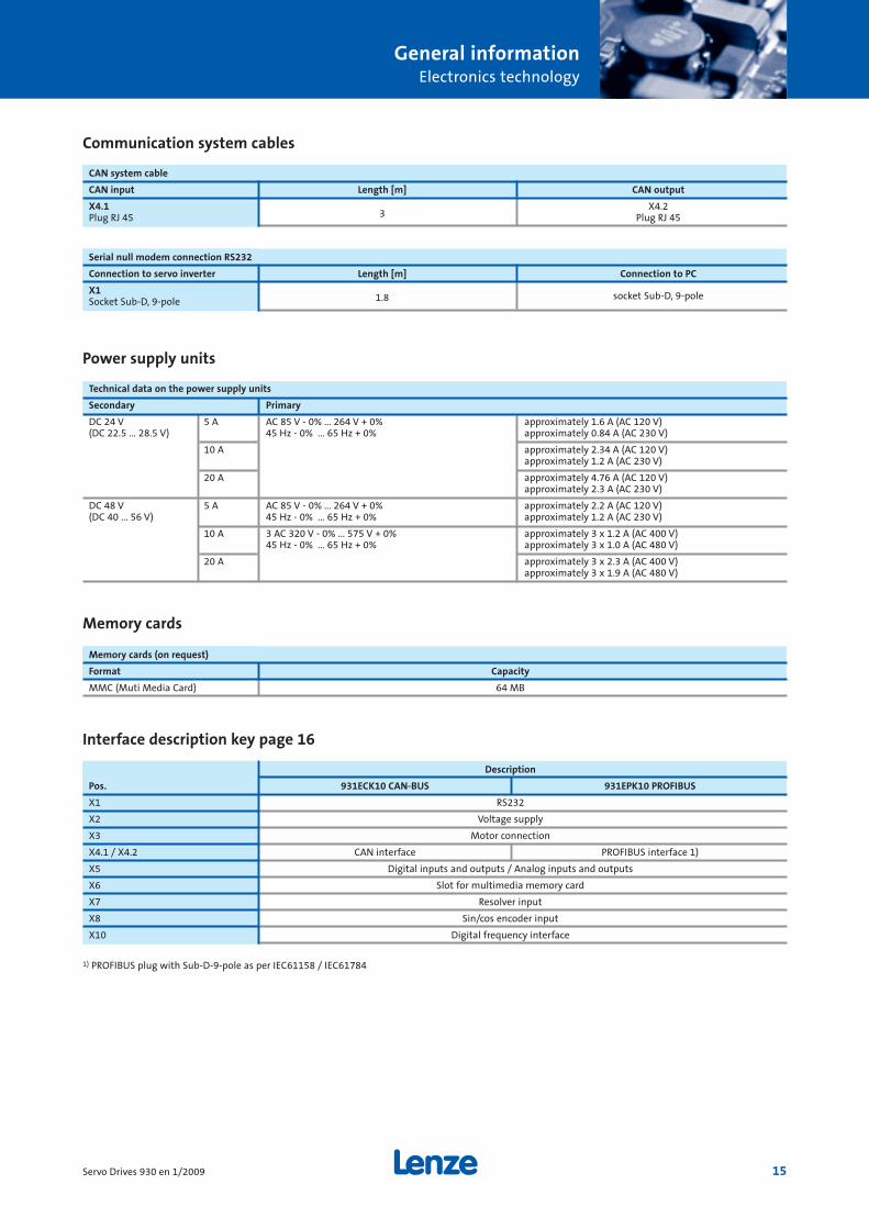
Technical data on the power supply units
Secondary Primary
DC 24 V 5 A AC 85 V - 0% ... 264 V + 0% approximately 1.6 A (AC 120 V)(DC 22.5 ... 28.5 V) 45 Hz - 0% ... 65 Hz + 0% approximately 0.84 A (AC 230 V)
10 A approximately 2.34 A (AC 120 V)approximately 1.2 A (AC 230 V)
20 A approximately 4.76 A (AC 120 V)approximately 2.3 A (AC 230 V)
DC 48 V 5 A AC 85 V - 0% ... 264 V + 0% approximately 2.2 A (AC 120 V)(DC 40 ... 56 V) 45 Hz - 0% ... 65 Hz + 0% approximately 1.2 A (AC 230 V)
10 A 3 AC 320 V - 0% ... 575 V + 0% approximately 3 x 1.2 A (AC 400 V)45 Hz - 0% ... 65 Hz + 0% approximately 3 x 1.0 A (AC 480 V)
20 A approximately 3 x 2.3 A (AC 400 V)approximately 3 x 1.9 A (AC 480 V)
Communication system cables
CAN system cable
CAN input Length [m] CAN output
X4.13
X4.2Plug RJ 45 Plug RJ 45
Serial null modem connection RS232
Connection to servo inverter Length [m] Connection to PC
X11.8Socket Sub-D, 9-pole
socket Sub-D, 9-pole
Memory cards
Memory cards (on request)
Format Capacity
MMC (Muti Media Card) 64 MB
Interface description key page 16
Description
Pos. 931ECK10 CAN-BUS 931EPK10 PROFIBUS
X1 RS232
X2 Voltage supply
X3 Motor connection
X4.1 / X4.2 CAN interface PROFIBUS interface 1)
X5 Digital inputs and outputs / Analog inputs and outputs
X6 Slot for multimedia memory card
X7 Resolver input
X8 Sin/cos encoder input
X10 Digital frequency interface
Power supply units
1) PROFIBUS plug with Sub-D-9-pole as per IEC61158 / IEC61784

16 Servo Drives 930 en 1/2009
General informationElectronics technology
Interface description
931ECK10 CAN bus communication (see page 15 for key)
931EPK10 PROFIBUS communication (see page 15 for key)

Technical data on Small Drives Control
The Small Drives Control application allows parametersetting of the servo position controller 931E.
The parameterisation software Lenze Small Drives Controlallows optimum adjustment of the servo position controller931E to the respective application. The parameter settingapplication offers the following performance features:
˘ Parameter setting of the servo position controller 931E
˘ Setting of all parameters via PC
˘ Display of status and operating values
˘ Loading of new firmware versions
˘ Loading and saving of parameter sets
˘ Printing of parameter sets
˘ Offline parameter setting
˘ Oscilloscope function
˘ Language support: German, English, French
˘ Free of charge software available via www.Lenze.de
General informationSoftware technology
17Servo Drives 930 en 1/2009

General informationMotor technology
18 Servo Drives 930 en 1/2009
Technical data on servo motors
Motor type SDSGS__ 035-22 SDSGS__ 035-22 SDSGS__ 047-22 SDSGS__ 056-22
Rated power 140 W 140 W 210 W 450 W
Rated torque 0.45 Nm 0.45 Nm 0.8 Nm 1.6 Nm
Rated current 8.4 A 4.0 A 6.2 A 12.5 A
Rated voltage 13 V 30 V 30 V 30 V
Rated frequency 100 Hz 100 Hz 83 Hz 90 Hz
Rated speed 3000 rpm 3000 rpm 2500 rpm 2700 rpm
Maximum speed (mech.) 6000 rpm 6000 rpm 6000 rpm 6000 rpm
Standstill torque 0.55 Nm 0.55 Nm 1.0 Nm 1.9 Nm
Continuous standstill current 9.5 A 4.4 A 7.2 A 13.6 A
Maximum current (demagnetisation current) 86 A 40 A 41 A 146 A
Maximum torque (mech.) 3.2 Nm 3.5 Nm 7.4 Nm 13.7 Nm
Speed constant [V/1000 r/min] 3.7 V/1000 rpm 7.5 V/1000 rpm 8.7 V/1000 rpm 8.7 V/1000 rpm
Torque constant [Nm/A] 0.058 Nm/A 0.124 Nm/A 0.14 Nm/A 0.14 Nm/A
RUV [Ω] 0.22 W 1.10 W 0.61 W 0.19 W
L phase 0.18 mH 0.585 mH 0.846 mH 0.280 mH
Moment of inertia 0.293 kgcm2 0.293kgcm2 0.444 kgcm2 1.466 kgcm2
General data and operating conditions
Design Smooth, round
Type Flange B14 as per DIN 42948 and IEC 72; Form C
Cooling Naturally ventilated
Insulation class F
Winding insulation max. voltage amplitude 1500 V; du/dt < 5 kV/μs
Permissible temperature range
Operation -20 °C ... + 40 °C
Enclosure IP54 as per DIN EN60034-5
Connection System connector
Temperature monitoring KTY 110
Speed feedback Pancake resolver (size 15) Absolute value encoder
Technical data on the spring-applied brake
Spring-applied brake Assigned motor frame size Brake voltage Characteristic torque Coil power at 20°C
BFK 457-02 SDSGSBS035 24 V 0.5 Nm 6.6 W
BFK 457-03 SDSGSBS047 24 V 1.0 Nm 9 W
BFK 457-04 SDSGSBS056 24 V 2.0 Nm 11.5 W
Technical data on the permanent magnetic brake
Permanent magnetic brake Assigned motor frame size Brake voltage Characteristic torque Coil power at 20°C
02.P1.130 SDSGSBS035 24 V 1.0 Nm 10W
03.P1.130 SDSGSBS047 24 V 2.0 Nm 11W
05.P1.130 SDSGSBS056 24 V 4.5 Nm 12W

Motor type
SDSGS 035-22 SDSGS 047-22 SDSGS 056-22
Max. radial force Fr at start of journal *) [N] 250 300 510
Max. radial force Fr at centre of journal *) [N] 260 350 550
Max. axial force Fa *) [N] 200 250 420
General informationMotor technology
19Servo Drives 930 en 1/2009
Mechanical data
*) Forces calculated for bearing life of 20,000 hours
Application points of radial force (Fr) and axial force (Fa)

Characteristics of SDSGSRS035-22 with 931E24 V 0.45 Nm 3000 rpm 140 W
Characteristics of SDSGSRS035-22 with 931E48 V 0.45 Nm 3000 rpm 140 W
General informationMotor technology
20 Servo Drives 930 en 1/2009
Speed [rpm]
Torq
ue
[Nm
]
max. values 2 sec.thermal limit
0
0.2
0.4
0.6
0.8
1,0
1.2
1.4
1.6
1.8
0 1000 2000 3000 4000 5000 6000
0.00
0.50
1.00
1.50
2.00
2.50
3.00
3.50
4.00
0 1000 2000 3000 4000 5000
Torq
ue
[Nm
]
Speed [rpm] max. values 2 sec.thermal limit

General informationMotor technology
Characteristics of SDSGSRS047-22 with 931E48 V 0.8 Nm 2500 rpm 210 W
Characteristics of SDSGSRS056-22 with 931E48 V 1.6 Nm 2700 rpm 450 W
Speed [rpm]
Torq
ue
[Nm
]
max. values 2 sec.thermal limit
0
1
2
3
4
5
0 1000 2000 3000 4000
0.00
0.50
1.00
1.50
2.00
2.50
3.00
3.50
4.00
4.50
5.00
0 1000 2000 3000 4000
Speed [rpm]
Torq
ue [N
m]
max. values 2 sec.thermal limit
21Servo Drives 930 en 1/2009
Torq
ue
[Nm
]

Drive selectionServo Drives 930
22 Servo Drives 930 en 1/2009
Selection table type 931EòK10
PN Description Design Controller type SelectionW Please mark as
appropriate
620 24-48V DC, 13A, max. 35A CAN bus 931ECK10Digital frequency coupling, digital and analog inputs/outputsResolver and absolute value encoder feedbackBrake controlPC interface RS232
620 24-48V DC, 13A, max. 35A PROFIBUS 931EPK10Digital frequency coupling, digital and analog inputs/outputsResolver and absolute value encoder feedbackBrake controlPC interface RS232
Servo Drives accessories
Servo Drives accessories SelectionPlease mark as
appropriate
System cable 931EKL03UBO (motor connection 2.5 m)
931EKL05UBO (motor connection 5 m)
931EKR03UBS (resolver connection 2.5 m)
931EKR05UBS (resolver connection 5 m)
931EKE03UBS (absolute value encoder connection 2.5 m)
931EKE05UBS (absolute value encoder connection 5 m)
931EKE03USS (digital frequency connection 3 m)
931EKC03USS (CAN plug/plug 3 m)
931EKS02UBB (PC connection RS232)
Memory card MMC-64 MB
CAN resistor 931EKC01UX (resistor)
Power supply unit 24 V/5 A, 230 V/50 Hz (control voltage)
24 V/10 A, 230 V/50 Hz
24 V/20 A, 230 V/50 Hz
48 V/5 A, 230 V/50 Hz
48 V/10 A, 400 V/50 Hz
48 V/20 A, 400 V/50 Hz
See page 6 for type code.See page 10 for mounting position.

Drive selectionServo Drives 930
23Servo Drives 930 en 1/2009
Dimensions
Clearance

Drive selectionSDSGS servo motors
24 Servo Drives 930 en 1/2009
Selection table for type SDSGSòòòòò-22
Supply PN Rated data Design Motor type Selectionvoltage V DC n2 M2 A-side Please mark as
V W rpm Nm appropriate
24 140 3000 0.45 IEC56 B14 C80 SDSGSòò035-22
48 140 3000 0.45 IEC56 B14 C80 SDSGSòò035-22
48 210 2500 0.80 IEC56 B14 C80 SDSGSòò047-22
48 210 2500 0.80 IEC63 B14 C90 SDSGSòò047-22
48 450 2700 1.60 IEC63 B14 C90 SDSGSòò056-22
Enclosure IP54
IP55
Design of B-side with resolver
with spring-applied brake and resolver
with permanent magnetic brake and resolver
with single-turn absolute value encoder
with multi-turn absolute value encoder
with spring-applied brake and single-turn absolute value encoder (not possible with motor frame size 035)
with spring-applied brake and multi-turn absolute value encoder (not possible with motor frame size 035)
with permanent magnetic brake and single-turn absolute value encoder
with permanent magnetic brake and multi-turn absolute value encoder
Position of electrical connection 2
Additional ordering details
See page 8 for type code.See page 10 for mounting position.

Drive selectionSDSGS servo motors
25Servo Drives 930 en 1/2009
Dimensions of type SDSGSòòòòò-22
Motor type Size a1 b1 c1 d d2 e1 f1 g g1 g2 i2 k k1j7 k6 BS* RS* AG*
SDSGSòò035-22 IEC56C80 79 50 12 9 M3 65 2.5 65 95 58 20 224 169 180
SDSGSòò047-22 IEC56C80 79 50 12 9 M3 65 2.5 75 101 58 20 253 189 200
SDSGSòò047-22 IEC63C90 89 60 12 11 M4 75 2.5 75 101 58 23 256 189 200
SDSGSòò056-22 IEC63C90 89 60 12 11 M4 75 2.5 85 106 58 23 271 196 207
Dimensions in mm
* see Page 8
Motor type Size k3 k4 l l1 l2 s1 r u x WeightBS* BA* approx. kg
SDSGSòò035-22 IEC56C80 138 204 225 20 3 14 M5 10.2 3 95 1.9-2.9
SDSGSòò047-22 IEC56C80 156 233 244 20 3 14 M5 10.2 3 115 3.0-4.0
SDSGSòò047-22 IEC63C90 156 233 244 23 3 18 M5 12.5 4 115 3.0-4.0
SDSGSòò056-22 IEC63C90 163 248 260 23 3 18 M5 12.5 4 120 4.0-5.5

Drive selectionServo worm geared motors SSN
26 Servo Drives 930 en 1/2009
Selection table for type SSN31-1Gòòò-035C22
PN Supply voltage for Servo Drive = 24 or 48 V DC Selection of
Motor type n2 M2 c i Please mark as W rpm Nm appropriate
SDSGSòò-035-22 140 600 1.91 7.32 5
429 2.61 5.35 7
300 3.47 4.04 10
200 5.00 3.20 15
150 6.21 2.42 20
120 6.86 2.04 25
100 7.97 1.88 30
79 9.75 1.64 38
60 10.35 1.26 50
55 12.87 1.17 55
40 11.00 0.91 75
30 11.00 0.64 100
Enclosure IP54
IP55
Design of B-side with resolver
with spring-applied brake and resolver
with permanent magnetic brake and resolver
with single-turn absolute value encoder
with multi-turn absolute value encoder
with permanent magnetic brake and single-turn absolute value encoder
with permanent magnetic brake and multi-turn absolute value encoder
Gearbox design VAR
DAR
VAL
HAR
VCR
DCR
VCL
HCR
Output flange diameter 100 mm
118.5 mm
120 mm
Shaft diameter 10 mm
12 mm
Shaft position on version VAR/VCR 3 5
Flange/shaft position on version VAL/VCL 3 5
Mounting position A B C D E F
Position of electrical connection 2 3 4 5
Additional ordering details
See page 9 for type code.See page 10 for mounting position.

Drive selectionServo worm geared motors SSN
27Servo Drives 930 en 1/2009
Dimensions for type SSN31-1Gòòò-035C22
Geared motor a1 a5 a6 b1 b5 b6 b7 c5 d e1 e5 f1 f5 f6 g g1 g2 h1 h2 kh8 h6 BS*
SSN31-1GVAR-035C22 63 25 25 32 50 50 40 5 10 50 54 2.5 78 78 65 95 58 31 40 278
SSN31-1GVAR-035C22 63 25 25 32 50 50 40 5 12 50 54 2.5 78 78 65 95 58 31 40 278
SSN31-1GVCR-035C22 63 – – 32 – – – – 10 50 54 2.5 – – 65 95 58 31 37.5 272
SSN31-1GVCR-035C22 63 – – 32 – – – – 12 50 54 2.5 – – 65 95 58 31 37.5 272
Geared motor k1 k1 k3 k4 k4 l l3 l4 m n1 n2 o q2 q4 s1 s5 t u x WeightRS* AG* BS* BA*
SSN31-1GVAR-035C22 164.5 176 134 200 220.5 30 4 25 50 26 24 78 60 90 M5 5.5 11.2 3 91 2.6-3.7
SSN31-1GVAR-035C22 164.5 176 134 200 220.5 40 4 28 50 26 24 78 70 100 M5 5.5 13.5 4 91 2.6-3.7
SSN31-1GVCR-035C22 164.5 176 134 200 220.5 30 4 25 – – – 72 60 90 M5 – 11.2 3 91 2.6-3.7
SSN31-1GVCR-035C22 164.5 176 134 200 220.5 40 4 28 – – – 72 70 100 M5 – 13.5 4 91 2.6-3.7
Dimensions in mm
* see Page 8

Drive selectionServo worm geared motors SSN
28 Servo Drives 930 en 1/2009
Dimensions for type SSN31-1Gòòò-035C22
Geared motor a2 b2 c2 d e2 f2 g g1 g2 h1 h2 k k1j7 h6 BS* RS*
SSN31-1GVAL-035C22 100 60 9 10 80 3 65 95 58 31 40 288 164.5
SSN31-1GVAL-035C22 120 80 9 12 100 3 65 95 58 31 40 298 164.5
SSN31-1GVCL-035C22 100 60 9 10 80 3 65 95 58 31 37.5 288 164.5
SSN31-1GVCL-035C22 118.5 80 11.5 12 100 3 65 95 58 31 37.5 298 164.5
Geared motor k1 k3 k4 k4 l l3 l4 o q2 q4 s2 t u x WeightAG* BS* BA*
SSN31-1GVAL-035C22 176 134 200 220.5 30 4 25 78 91.5 121.5 M6 11.2 3 91 2.6-3.7
SSN31-1GVAL-035C22 176 134 200 220.5 40 4 28 78 101.5 131.5 M6 13.5 4 91 2.6-3.7
SSN31-1GVCL-035C22 176 134 200 220.5 30 4 25 72 91.5 121.5 M6 11.2 3 91 2.6-3.7
SSN31-1GVCL-035C22 176 134 200 220.5 40 4 28 72 113 143 M6 13.5 4 91 2.6-3.7
Dimensions in mm
* see Page 8

Drive selectionServo worm geared motors SSN
29Servo Drives 930 en 1/2009
Dimensions for type SSN31-1Gòòò-035C22
Geared motor a1 a5 a6 a7 b1 b5 b6 b7 c5 d d1 e1 e4 e5 f1 f5 f6 g g1 g2 h h1 h2h8 h7
SSN31-1GHAR-035C22 63 25 25 75 40 50 50 40 5 15 25 50 50 54 2.5 78 78 65 95 58 71 31 40
SSN31-1GHCR-035C22 63 – – 75 40 – – – – 15 25 50 50 54 2.5 – – 65 95 58 68.5 31 37.5
Geared motor i k k1 k1 k3 k4 k4 l m n1 n2 o p q s1 s4 s5 s6 t u x WeightBS* RS* AG* BS* BA*
SSN31-1GHAR-035C22 2 278 164.5 176 134 200 220.5 63 50 26 24 78 166 27 M5 6.5 5.5 6 17.3 5 91 2.6-3.7
SSN31-1GHCR-035C22 2 272 164.5 176 134 200 220.5 63 – – – 72 163.5 27 M5 6.5 – 6 17.3 5 91 2.6-3.7
Dimensions in mm
* see Page 8
Drive selectionServo worm geared motors SSN
30 Servo Drives 930 en 1/2009
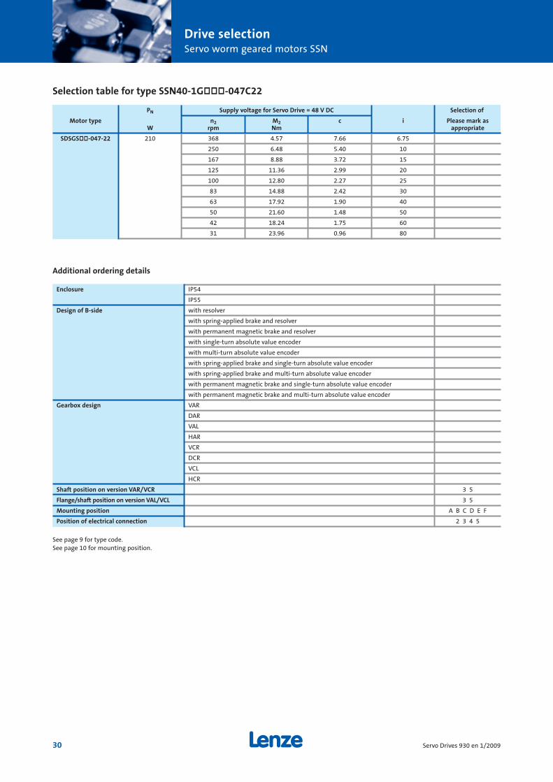
Selection table for type SSN40-1Gòòò-047C22
Enclosure IP54
IP55
Design of B-side with resolver
with spring-applied brake and resolver
with permanent magnetic brake and resolver
with single-turn absolute value encoder
with multi-turn absolute value encoder
with spring-applied brake and single-turn absolute value encoder
with spring-applied brake and multi-turn absolute value encoder
with permanent magnetic brake and single-turn absolute value encoder
with permanent magnetic brake and multi-turn absolute value encoder
Gearbox design VAR
DAR
VAL
HAR
VCR
DCR
VCL
HCR
Shaft position on version VAR/VCR 3 5
Flange/shaft position on version VAL/VCL 3 5
Mounting position A B C D E F
Position of electrical connection 2 3 4 5
Additional ordering details
See page 9 for type code.See page 10 for mounting position.
PN Supply voltage for Servo Drive = 48 V DC Selection of
Motor type n2 M2 c i Please mark asW rpm Nm appropriate
SDSGSòò-047-22 210 368 4.57 7.66 6.75
250 6.48 5.40 10
167 8.88 3.72 15
125 11.36 2.99 20
100 12.80 2.27 25
83 14.88 2.42 30
63 17.92 1.90 40
50 21.60 1.48 50
42 18.24 1.75 60
31 23.96 0.96 80

Drive selectionServo worm geared motors SSN
31Servo Drives 930 en 1/2009
Dimensions for type SSN40-1Gòòò-047C22
Geared motor a1 a5 a6 b1 b5 b6 b7 c5 d e1 e5 f1 f5 f6 g g1 g2 h1 h2 kh10 h6 BS*
SSN40-1GVAR-047C22 77 30 30 44 60 60 50 6 15 65 80 2 90 90 75 101 58 40 48 323
SSN40-1GVCR-047C22 77 – – 44 – – – – 15 65 80 2 – – 75 101 58 40 40 315
Geared motor k1 k1 k3 k4 k4 l l3 l4 m n1 n2 o q2 q4 s1 s5 t u x WeightRS* AG* BS* BA*
SSN40-1GVAR-047C22 183 194.5 150.5 227 238.5 43 4 36 59 30 24 96 83 123 M6 5.5 17 5 109.5 4.5-5.8
SSN40-1GVCR-047C22 183 194.5 150.5 227 238.5 43 4 36 – – – 88 83 123 M6 – 17 5 109.5 4.5-5.8
Dimensions in mm
* see Page 8

Drive selectionServo worm geared motors SSN
32 Servo Drives 930 en 1/2009
Dimensions for type SSN40-1Gòòò-047C22
Geared motor a2 b2 c2 d e2 f2 g g1 g2 h1 h2 k k1j7 h6 BS* RS*
SSN40-1GVAL-047C22 140 95 10 15 115 3 75 101 58 40 48 345 183
SSN40-1GVCL-047C22 140 95 10 15 115 3 75 101 58 40 40 345 183
Geared motor k1 k3 k4 k4 l l3 l4 o q2 q4 s2 t u x WeightAG* BS* BA*
SSN40-1GVAL-047C22 194.5 150.5 227 238.5 50 4 36 96 128 168 M8 17 5 109.5 4.5-5.8
SSN40-1GVCL-047C22 194.5 150.5 227 238.5 50 4 36 88 128 168 M8 17 5 109.5 4.5-5.8
Dimensions in mm
* see Page 8

Drive selectionServo worm geared motors SSN
33Servo Drives 930 en 1/2009
Dimensions for type SSN40-1Gòòò-047C22
Geared motor a1 a5 a6 a7 b1 b5 b6 b7 c5 d d1 e1 e4 e5 f1 f5 f6 g g1 g2 h h1 h2h8 H7
SSN40-1GHAR-047C22 77 30 30 85 50 60 60 50 6 20 30 65 65 80 2 90 90 75 101 58 88 40 48
SSN40-1GHCR-047C22 77 – – 85 50 – – – – 20 30 65 65 80 2 – – 75 101 58 80 40 40
Dimensions in mm
* see Page 8
Geared motor i k k1 k1 k3 k4 k4 l m n1 n2 o p q s1 s4 s5 s6 t u x WeightBS* RS* AG* BS* BA*
SSN40-1GHAR-047C22 1.5 323 183 194.5 150.5 227 238.5 83 59 30 24 96 189 41.5 M6 8 5.5 7 22.8 6 109.5 4.5-5.8
SSN40-1GHCR-047C22 1.5 315 183 194.5 150.5 227 238.5 83 – – – 88 181 41.5 M6 8 – 7 22.8 6 109.5 4.5-5.8

Drive selectionPlanetary geared servo motors SPL
34 Servo Drives 930 en 1/2009
Selection table for type SPL52-òGVCR-035N22
Enclosure IP54
IP55
Design of B-side with resolver
with spring-applied brake and resolver
with permanent magnetic brake and resolver
with single-turn absolute value encoder
with multi-turn absolute value encoder
with permanent magnetic brake and single-turn absolute value encoder
with permanent magnetic brake and multi-turn absolute value encoder
Position of electrical connection 2
Additional ordering details
See page 9 for type code.See page 10 for mounting position.
PN Supply voltage for Servo Drive = 24 or 48 V DC Selection of
Motor type n2 M2 c i 1-stage Please mark asW rpm Nm appropriate
SDSGSòò-035-22 140 811 1.33 3.00 3.70
444 2.43 1.65 6.75
i 2-stage
218 4.63 2.59 13.73
120 8.44 1.42 25.01
66 15.38 0.78 45.56
i 3-stage
59 16.03 1.56 50.89
32 25.00 0.86 92.70

Drive selectionPlanetary geared servo motors SPL
35Servo Drives 930 en 1/2009
Dimensions for type SPL52-òGVCR-035N22
Geared motor Ratio b1 d d2 e1 f1 g g1 g2 g4 g5 i1 ki h8 h7 BS*
3.7;6.7 303
SPL52-òGVCR-035N22 14 … 46 32 12 M4 40 3 52 65 58 95 80 25 317
51 … 93 331
Geared motor Ratio k1 k1 k3 k4 k4 l l1 l2 o1 s1 t u x Weighti RS* AG* BS* BA*
3.7;6.7 99 2.6-3.6
SPL52-òGVCR-035N22 14 … 46 169 180 138 204 225 20.8 2.5 16 113 M5x10 13.5 4 95 2.8-3.8
51 … 93 127 3.0-4.0
Dimensions in mm
* see Page 8

Drive selectionPlanetary geared servo motors SPL
36 Servo Drives 930 en 1/2009
Selection table for type SPL62-òGVCR-035N22
Enclosure IP54
IP55
Design of B-side with resolver
with spring-applied brake and resolver
with permanent magnetic brake and resolver
with single-turn absolute value encoder
with multi-turn absolute value encoder
with permanent magnetic brake and single-turn absolute value encoder
with permanent magnetic brake and multi-turn absolute value encoder
Position of electrical connection 2
Additional ordering details
See page 9 for type code.See page 10 for mounting position.
PN Supply voltage for Servo Drive = 24 or 48 V DC Selection of
Motor type n2 M2 c i 1-stage Please mark asW rpm Nm appropriate
SDSGSòò-035-22 140 811 1.33 6.01 3.70
444 2.43 3.29 6.75
i 2-stage
218 4.63 5.40 13.73
120 8.44 2.96 25.01
86 11.80 2.12 34.97
66 15.38 1.63 45.56
i 3-stage
59 16.03 3.12 50.89
42 22.42 2.23 71.16
30 31.34 1.60 99.50
24 39.05 1.28 123.97

Drive selectionPlanetary geared servo motors SPL
37Servo Drives 930 en 1/2009
Dimensions for type SPL62-òGVCR-035N22
Geared motor Ratio b1 d d2 e1 f1 g g1 g2 g4 g5 i1 ki j7 h7 BS*
3.7;6.7 340
SPL62-òGVCR-035N22 14 … 46 40 14 M5 52 5 62 65 58 95 80 39 356
51 … 124 372
Geared motor Ratio k1 k1 k3 k4 k4 l l1 l2 o1 s1 t u x Weight i RS* AG* BS* BA*
3.7;6.7 115 2.8-3.8
SPL62-òGVCR-035N22 14 … 46 169 180 138 204 225 30 5.5 18 131 M5x10 16 5 95 3.2-4.2
51 … 124 147 3.6-4.6
Dimensions in mm
* see Page 8

Drive selectionPlanetary geared servo motors SPL
38 Servo Drives 930 en 1/2009
Selection table for type SPL62-òGVCR-047N22
Enclosure IP54
IP55
Design of B-side with resolver
with spring-applied brake and resolver
with permanent magnetic brake and resolver
with single-turn absolute value encoder
with multi-turn absolute value encoder
with spring-applied brake and single-turn absolute value encoder
with spring-applied brake and multi-turn absolute value encoder
with permanent magnetic brake and single-turn absolute value encoder
with permanent magnetic brake and multi-turn absolute value encoder
Position of electrical connection 2
Additional ordering details
See page 9 for type code.See page 10 for mounting position.
PN Supply voltage for Servo Drive = 48 V DC Selection of
Motor type n2 M2 c i 1-stage Please mark asW rpm Nm appropriate
SDSGSòò-047-22 210 676 2.37 3.38 3.70
370 4.32 1.85 6.75
i 2-stage
182 8.24 3.03 13.73
100 15.01 1.67 25.01
72 20.98 1.19 34.97
55 25.00 0.91 45.56
i 3-stage
49 28.50 1.75 50.89
35 39.85 1.25 71.16

Drive selectionPlanetary geared servo motors SPL
39Servo Drives 930 en 1/2009
Dimensions for type SPL62-òGVCR-047N22
Geared motor Ratio b1 d d2 e1 f1 g g1 g2 g4 g5 i1 ki j7 h7 BS*
3.7;6.7 348
SPL62-òGVCR-047N22 14 … 46 40 14 M5 52 5 62 75 58 101 80 39 364
51 … 71 380
Geared motor Ratio k1 k1 k3 k4 k4 l l1 l2 o1 s1 t u x WeightRS* AG* BS* BA*
3.7;6.7 115 3.8-4.8
SPL62-òGVCR-047N22 14 … 46 189 200 156 233 244 30 5.5 18 131 M5x10 16 5 115 4.2-5.2
51 … 71 147 4.6-5.6
Dimensions in mm
* see Page 8

Drive selectionPlanetary geared servo motors SPL
40 Servo Drives 930 en 1/2009
Selection table for type SPL81-òGVCR-056N22
Enclosure IP54
IP55
Design of B-side with resolver
with spring-applied brake and resolver
with permanent magnetic brake and resolver
with single-turn absolute value encoder
with multi-turn absolute value encoder
with spring-applied brake and single-turn absolute value encoder
with spring-applied brake and multi-turn absolute value encoder
with permanent magnetic brake and single-turn absolute value encoder
with permanent magnetic brake and multi-turn absolute value encoder
Position of electrical connection 2
Additional ordering details
See page 9 for type code.See page 10 for mounting position.
PN Supply voltage for Servo Drive = 48 V DC Selection of
Motor type n2 M2 c i 1-stage Please mark asW rpm Nm appropriate
SDSGSòò-056-22 450 730 4.74 4.22 3.700
400 8.64 2.31 6.750
i 2-stage
197 16.48 3.64 13.730
108 30.01 2.00 25.010
77 41.96 1.43 34.970
59 54.67 1.10 45.560
i 3-stage
53 57.00 2.11 50.890
38 79.70 1.51 71.160
27 111.44 1.08 99.500
22 120.00 0.86 123.970

Drive selectionPlanetary geared servo motors SPL
41Servo Drives 930 en 1/2009
Selection table for type SPL81-òGVCR-056N22
Geared motor Ratio b1 d d2 e1 f1 g g1 g2 g4 g5 i1 ki j7 h7 BS*
3.7;6.7 392
SPL81-òGVCR-056N22 14 … 46 50 19 M6 65 5 81 85 58 106 90 49 413
51 … 124 435
Geared motor Ratio k1 k1 k3 k4 k4 l l1 l2 o1 s1 t u x Weighti RS* AG* BS* BA*
3.7;6.7 144 6.1-7.6
SPL81-òGVCR-056N22 14 … 46 196 207 163 248 260 40 6 28 165 M6x12 21.5 6 120 6.8-8.3
51 … 124 187 7.5-9.0
Dimensions in mm
* see Page 8

Drive selectionHelical geared servo motors GST
42 Servo Drives 930 en 1/2009
Selection table for type GST03-2GVòò-035C22
PN Supply voltage for Servo Drive = 24 or 48 V DC Selection of
Motor type n2 M2 c i Please mark asW rpm Nm appropriate
SDSGSòò-035-22 140 1155.20 1.00 13.37 2.597
879.00 1.00 10.85 3.413
686.80 2.00 9.01 4.368
564.80 2.00 9.59 5.312
502.90 3.00 8.93 5.965
429.70 3.00 7.96 6.982
382.70 3.00 7.68 7.840
335.80 4.00 6.74 8.935
299.00 4.00 6.46 10.033
262.50 5.00 5.87 11.429
233.80 6.00 5.59 12.833
202.20 6.00 4.99 14.836
180.10 7.00 5.28 16.660
157.80 8.00 4.75 19.013
140.50 9.00 4.45 21.350
122.00 11.00 3.95 24.595
108.60 12.00 3.52 27.618
93.80 14.00 3.04 32.000
83.50 16.00 2.71 35.933
72.40 18.00 2.35 41.455
64.40 20.00 2.24 46.550
56.70 23.00 1.97 52.909
50.50 26.00 1.75 59.413
Enclosure IP54
IP55
Design of B-side with resolver
with spring-applied brake and resolver
with permanent magnetic brake and resolver
with single-turn absolute value encoder
with multi-turn absolute value encoder
with permanent magnetic brake and single-turn absolute value encoder
with permanent magnetic brake and multi-turn absolute value encoder
Gearbox design VBR
VCR
VCK
Output flange diameter 120 mm
140 mm
160 mm
Mounting position A B C D E F
Position of electrical connection 2 3 4 5
Additional ordering details
See page 9 for type code.See page 10 for mounting position.

43Servo Drives 930 en 1/2009
Dimensions for type GST03-2GVòò-035C22
Drive selectionHelical geared servo motors GST
Geared motor a a1 a2 b1 b2 b5 b7 c2 c5 d d2 e1 e2 e5 f1 f2 f5 g g1 g2 h i i1 i2 i5h7 j7 k6
120 80 14 M5 100 3 28 40
GST03-2GVòò-035C22 2 71 140 48 95 60 91 10 11 20 M6 61 115 105 8 3 84 65 95 58 65 46 51 40 52
160 110 130 3.5
Geared motor k k1 k1 k2 k3 k4 k4 l l1 l2 m o o1 p p1 p2 s1 s2 s5 t u x WeightBS* RS* AG* BS* BA*
339.5 28 4 20 137.5 7
GST03-2GVòò-035C22 351.5 166.5 178 100 136 202 222.5 40 5 28 20 90 149.5 100 64 101 M5 9 6.6 22.5 6 93 5.0-6.5
9
Dimensions in mm
* see Page 8

Drive selectionHelical geared servo motors GST
44 Servo Drives 930 en 1/2009
Selection table for type GST03-2GVòò-047C22
PN Supply voltage for Servo Drive = 48 V DC Selection of
Motor type n2 M2 c i Please mark as W rpm Nm appropriate
SDSGSòò-047-22 210 962.60 2.00 7.52 2.597
732.50 3.00 6.10 3.413
572.30 3.00 5.07 4.368
470.60 4.00 5.39 5.312
419.10 5.00 5.02 5.965
358.10 5.00 4.48 6.982
318.90 6.00 4.32 7.840
279.80 7.00 3.79 8.935
249.20 8.00 3.63 10.033
218.70 9.00 3.30 11.429
194.80 10.00 3.15 12.833
168.50 11.00 2.81 14.836
150.10 13.00 2.97 16.660
131.50 15.00 2.67 19.013
117.10 16.00 2.50 21.350
101.60 19.00 2.22 24.595
90.50 21.00 1.98 27.618
78.10 25.00 1.71 32.000
69.60 28.00 1.52 35.933
60.30 32.00 1.32 41.455
53.70 36.00 1.26 46.550
47.30 41.00 1.11 52.909
42.10 45.00 1.00 59.413
Enclosure IP54
IP55
Design of B-side with resolver
with spring-applied brake and resolver
with permanent magnetic brake and resolver
with single-turn absolute value encoder
with multi-turn absolute value encoder
with spring-applied brake and single-turn absolute value encoder
with spring-applied brake and multi-turn absolute value encoder
with permanent magnetic brake and single-turn absolute value encoder
with permanent magnetic brake and multi-turn absolute value encoder
Gearbox design VBR
VCR
VCK
Output flange diameter 120 mm
140 mm
160 mm
Mounting position A B C D E F
Position of electrical connection 2 3 4 5
Additional ordering details
See page 9 for type code.See page 10 for mounting position.

Drive selectionHelical geared servo motors GST
45Servo Drives 930 en 1/2009
Dimensions for type GST03-2GVòò-047C22
Geared motor a a1 a2 b1 b2 b5 b7 c2 c5 d d2 e1 e2 e5 f1 f2 f5 g g1 g2 h i i1 i2 i5h7 j7 k6
120 80 14 M5 100 3 28 40
GST03-2GVòò-047C22 2 71 140 48 95 60 91 10 11 20 M6 61 115 105 8 3 84 75 101 58 65 46 51 40 52
160 110 130 3.5
Geared motor k k1 k1 k2 k3 k4 k4 l l1 l2 m o o1 p p1 p2 s1 s2 s5 t u x WeightBS* RS* AG* BS* BA*
372.5 28 4 20 137.5 7
GST03-2GVòò-047C22 384.5 191 202.5 100 158.5 235 246.5 40 5 28 20 90 149.5 100 64 101 M5 9 6.6 22.5 6 117.5 6.0-7.5
9
Dimensions in mm
* see Page 8

46 Servo Drives 930 en 1/2009
Selection table for type GST04-1GVòò-056C22
PN Supply voltage for Servo Drive = 48 V DC Selection of
Motor type n2 M2 c i Please mark asW rpm Nm appropriate
SDSGSòò-056-22 450 1687.50 3.00 3.83 1.600
1318.40 3.00 3.74 2.048
1205.40 4.00 3.87 2.240
945.00 4.00 3.39 2.857
771.40 5.00 2.92 3.500
613.60 7.00 2.32 4.400
476.40 9.00 1.80 5.667
375.90 11.00 1.42 7.182
300.00 14.00 1.08 9.000
Enclosure IP54
IP55
Design of B-side with resolver
with spring-applied brake and resolver
with permanent magnetic brake and resolver
with single-turn absolute value encoder
with multi-turn absolute value encoder
with spring-applied brake and single-turn absolute value encoder
with spring-applied brake and multi-turn absolute value encoder
with permanent magnetic brake and single-turn absolute value encoder
with permanent magnetic brake and multi-turn absolute value encoder
Gearbox design VBR
VCR
VCK
Output flange diameter 120 mm
140 mm
160 mm
Mounting position A B C D E F
Position of electrical connection 2 3 4 5
Additional ordering details
See page 9 for type code.See page 10 for mounting position.
Drive selectionHelical geared servo motors GST

Drive selectionHelical geared servo motors GST
47Servo Drives 930 en 1/2009
Dimensions for type GST04-1GVòò-056C22
Geared motor a a1 a2 b1 b2 b5 b7 c2 c5 d d2 e1 e2 e5 f1 f2 f5 g g1 g2 h i i1 i2 i5h7 j7 k6
36 72 120 48 80 55 105 10 17 16 M5 61 100 130 8 3 80 75 101 58 50 35 43 32 45
GST04-1GVòò-047C22 140 95 115 3
160 110 130 3.5
Geared motor k k1 k1 k2 k3 k4 k4 k8 l l1 l2 m n n1 o o1 p p1 p2 s1 s2 s5 t u x WeightBS* RS* AG* BS* BA*
364.5 182 193 129 149 226 237 35 32 6 20 25 20 25 115 138.5 129 41 138 M5 7 9 18 5 103.5 6.5-8.0
GST04-1GVòò-047C22 9
9
Dimensions in mm
* see Page 8

Drive selectionHelical geared servo motors GST
48 Servo Drives 930 en 1/2009
Selection table for type GST04-2GVòò-056C22
PN Supply voltage for Servo Drive = 48 V DC Selection of
Motor type n2 M2 c i Please mark as W rpm Nm appropriate
SDSGSòò-056-22 450 913.40 5.00 3.88 2.956
810.10 5.00 3.91 3.333
666.20 6.00 3.86 4.053
590.70 7.00 3.87 4.571
520.50 8.00 3.82 5.187
461.50 9.00 3.83 5.850
421.90 10.00 3.66 6.400
383.50 11.00 3.40 7.040
337.50 12.00 3.13 8.000
299.70 14.00 2.95 9.010
273.90 15.00 2.80 9.856
241.10 17.00 2.28 11.200
214.80 19.00 2.32 12.571
189.00 22.00 1.79 14.286
175.30 24.00 2.16 15.400
154.30 27.00 1.70 17.500
139.50 30.00 1.75 19.360
122.70 34.00 1.35 22.000
108.30 38.00 1.38 24.933
95.30 44.00 1.08 28.333
85.40 49.00 1.10 31.600
75.20 47.00 0.86 35.909
68.20 54.00 0.88 39.600
60.00 52.00 0.75 45.000
Enclosure IP54
IP55
Design of B-side with resolver
with spring-applied brake and resolver
with permanent magnetic brake and resolver
with single-turn absolute value encoder
with multi-turn absolute value encoder
with spring-applied brake and single-turn absolute value encoder
with spring-applied brake and multi-turn absolute value encoder
with permanent magnetic brake and single-turn absolute value encoder
with permanent magnetic brake and multi-turn absolute value encoder
Gearbox design VBR
VCR
VCK
Output flange diameter 120 mm
140 mm
160 mm
Mounting position A B C D E F
Position of electrical connection 2 3 4 5
Additional ordering details
See page 9 for type code.See page 10 for mounting position.

Drive selectionHelical geared servo motors GST
49Servo Drives 930 en 1/2009
Dimensions for type GST04-2GVòò-056C22
Geared motor a a1 a2 b1 b2 b5 b7 c2 c5 d d2 e1 e2 e5 f1 f2 f5 g g1 g2 h i i1 i2 i5h7 j7 k6
0 72 120 48 80 76 105 10 18 20 M6 61 100 130 8 3 112 85 106 58 80 43 51 40 53
GST04-2GVòò-056C22 140 95 115 3
160 110 130 3.5
Geared motor k k1 k1 k2 k3 k4 k4 l l1 l2 m n n1 o o1 p p1 p2 s1 s2 s5 t u x WeightBS* RS* AG* BS* BA*
419.5 188.5 200 129 156 241 252.5 40 5 28 25 20 36 115 178.5 129 77 132 M5 7 9 22.5 6 113 9.5-11
GST04-2GVòò-056C22 9
9
Dimensions in mm
* see Page 8

Drive selectionBevel geared servo motors GKR
50 Servo Drives 930 en 1/2009
Selection table for type GKR03-2GòAò-035C22
PN Supply voltage for Servo Drive = 24 or 48 V DC Selection of
Motor type n2 M2 c i Please mark asW rpm Nm appropriate
SDSGSòò-035-22 140 554.40 2.00 13.83 5.411
482.20 3.00 12.41 6.222
421.90 3.00 11.51 7.111
366.80 3.00 10.30 8.178
329.60 4.00 9.51 9.101
286.60 4.00 8.27 10.466
257.70 5.00 7.44 11.64
224.10 6.00 6.47 13.386
198.50 6.00 5.73 15.111
172.60 7.00 4.98 17.378
154.90 8.00 4.47 19.365
134.70 10.00 3.89 22.27
119.80 11.00 3.92 25.051
104.10 12.00 3.41 28.808
92.00 14.00 3.01 32.593
80.00 16.00 2.62 37.481
71.10 18.00 2.49 42.222
61.80 21.00 2.17 48.556
55.70 23.00 1.95 53.889
48.40 26.00 1.70 61.972
Enclosure IP54
IP55
Design of B-side with resolver
with spring-applied brake and resolver
with permanent magnetic brake and resolver
with single-turn absolute value encoder
with multi-turn absolute value encoder
with permanent magnetic brake and single-turn absolute value encoder
with permanent magnetic brake and multi-turn absolute value encoder
Gearbox design VAR
VAK
HAR
HAK
Output flange diameter 110 mm
120 mm
Hollow shaft bore 18 mm
20 mm
Shaft position on version VAR 3 5 8
Flange-shaft position on version VAK 3 5
Flange position on version HAK 3 5
Mounting position A B C D E F
Position of electrical connection 2 3 4 5
Additional ordering details
See page 9 for type code.See page 10 for mounting position.

Drive selectionBevel geared servo motors GKR
51Servo Drives 930 en 1/2009
Dimensions for type GKR03-2GòAò-035C22
Dimensions in mm
* see Page 8
Geared motor a a1 a2 b1 b2 b3 b5 b7 c2 c5 d d1 e1 e2 e5 f1 f2 f3 f5 g g1 g2 h i1 i2 kJ7 j7 H7 H7 BS*
GKR03-2GHAò-035C2229 84 120 55 80 – 60 75 8 7 18 30 70 100 90 3 3 – 80 65 95 58 50 2.5 30 354
110 – 60 20 30 87 4
Geared motor k1 k1 k2 k3 k4 k4 l l1 m n o o1 p p1 q q1 s1 s2 s5 t u x WeightRS* AG* BS* BA*
GKR03-2GHAò-035C22166.5 178 100 136 202 222.5 100 86 22 20 152 130 117 48 50 80 M6 7 6.6 20.8 6 93 5.0-6.5
9 22.8 6

Drive selectionBevel geared servo motors GKR
52 Servo Drives 930 en 1/2009
Geared motor a a1 a2 b1 b2 b3 b5 b7 c2 c5 d d2 e1 e2 e5 f1 f2 f3 f5 g g1 g2 h i1 i2J7 j7 H7 k6
GKR03-2GVAò-035C2229 84 120 55 80 – 60 75 8 7 20 M6 70 100 90 2.5 3 – 80 65 95 58 50 42.5 40
110 – 60 87 4
Geared motor k k1 k1 k2 k3 k4 k4 l l1 l2 m n o o1 o2 p p1 q q1 s1 s2 s5 t u x WeightBS* RS* AG* BS* BA*
GKR03-2GVAò-035C22354 166.5 178 100 136 202 222.5 40 5 28 22 20 152 138 168 117 48 90 80 M6 7 6.6 22.5 6 93 5.0-6.5
9 6
Dimensions for type GKR03-2GòAò-035C22
Dimensions in mm
* see Page 8

53Servo Drives 930 en 1/2009

Drive selectionBevel geared servo motors GKR
54 Servo Drives 930 en 1/2009
Selection table for type GKR03-2GòAò-047C22
PN Supply voltage for Servo Drive = 48 V DC Selection of
Motor type n2 M2 c i Please mark as W rpm Nm appropriate
SDSGSòò-047-22 210 462.00 4.00 7.78 5.411
401.80 5.00 6.98 6.222
351.60 5.00 6.48 7.111
305.70 6.00 5.79 8.178
274.70 7.00 5.35 9.101
238.90 8.00 4.65 10.466
214.80 9.00 4.18 11.64
186.80 10.00 3.64 13.386
165.40 11.00 3.22 15.111
143.90 13.00 2.80 17.378
129.10 15.00 2.51 19.365
112.30 17.00 2.19 22.27
99.80 19.00 2.21 25.051
86.80 22.00 1.92 28.808
76.70 25.00 1.70 32.593
66.70 28.00 1.47 37.481
59.20 32.00 1.40 42.222
51.50 37.00 1.22 48.556
46.40 41.00 1.10 53.889
40.30 45.00 0.96 61.972
Enclosure IP54
IP55
Design of B-side with resolver
with spring-applied brake and resolver
with permanent magnetic brake and resolver
with single-turn absolute value encoder
with multi-turn absolute value encoder
with spring-applied brake and single-turn absolute value encoder
with spring-applied brake and multi-turn absolute value encoder
with permanent magnetic brake and single-turn absolute value encoder
with permanent magnetic brake and multi-turn absolute value encoder
Gearbox design VAR
VAK
HAR
HAK
Output flange diameter 110 mm
120 mm
Hollow shaft bore 18 mm
20 mm
Shaft position on version VAR 3 5 8
Flange-shaft position on version VAK 3 5
Flange position on version HAK 3 5
Mounting position A B C D E F
Position of electrical connection 2 3 4 5
Additional ordering details
See page 9 for type code.See page 10 for mounting position.

Dimensions for type GKR03-2GòAò-047C22
Geared motor k1 k1 k2 k3 k4 k4 l l1 m n o o1 p p1 q q1 s1 s2 s5 t u x WeightRS* AG* BS* BA*
GKR03-2GHAò-047C22191 202.5 100 158.5 235 246.5 100 86 22 20 152 130 117 48 50 80 M6 7 6.6 20.8 6 117.5 6.0-7.5
9 22.8 6
Dimensions in mm
* see Page 8
Drive selectionBevel geared servo motors GKR
55Servo Drives 930 en 1/2009
Geared motor a a1 a2 b1 b2 b3 b5 b7 c2 c5 d d1 e1 e2 e5 f1 f2 f3 f5 g g1 g2 h i1 i2 kJ7 j7 H7 H7 BS*
GKR03-2GHAò-047C2229 84 120 55 80 – 60 75 8 7 18 30 70 100 90 3 3 – 80 75 101 58 50 2.5 30 387
110 – 60 20 30 87 4

Drive selectionBevel geared servo motors GKR
56 Servo Drives 930 en 1/2009
Dimensions for type GKR03-2GòAò-047C22
Geared motor a a1 a2 b1 b2 b3 b5 b7 c2 c5 d d2 e1 e2 e5 f1 f2 f3 f5 g g1 g2 h i1 i2J7 j7 H7 k6
GKR03-2GVAò-047C2229 84 120 55 80 – 60 75 8 7 20 M6 70 100 90 2.5 3 – 80 75 101 58 50 42.5 40
110 – 60 87 4
Geared motor k k1 k1 k2 k3 k4 k4 l l1 l2 m n o o1 o2 p p1 q q1 s1 s2 s5 t u x WeightBS* RS* AG* BS* BA*
GKR03-2GVAò-047C22387 191 202.5 100 158.5 235 246.5 40 5 28 22 20 152 138 168 117 48 90 80 M6 7 6.6 22.5 6 117.5 6.0-7.5
9 6
Dimensions in mm
* see Page 8

57Servo Drives 930 en 1/2009

Drive selectionBevel geared servo motors GKR
58 Servo Drives 930 en 1/2009
Selection table for type GKR04-2GòAò-056C22
PN Supply voltage for Servo Drive = 48 V DC Selection of
Motor type n2 M2 c i Please mark as W rpm Nm appropriate
SDSGSòò-056-22 450 520.70 8.00 3.86 5.185
452.80 9.00 3.80 5.963
379.70 11.00 3.77 7.111
330.20 12.00 3.80 8.178
296.70 14.00 3.82 9.101
258.00 16.00 3.62 10.466
235.80 17.00 3.36 11.449
212.60 19.00 3.03 12.698
184.90 22.00 2.63 14.603
173.60 24.00 2.47 15.556
150.90 27.00 2.15 17.889
138.10 30.00 1.96 19.556
120.10 34.00 1.71 22.489
107.20 38.00 1.73 25.185
93.20 44.00 1.51 28.963
84.60 49.00 1.37 31.919
73.60 56.00 1.19 36.707
67.50 61.00 1.09 40.000
58.70 70.00 1.03 46.000
Enclosure IP54
IP55
Design of B-side with resolver
with spring-applied brake and resolver
with permanent magnetic brake and resolver
with single-turn absolute value encoder
with multi-turn absolute value encoder
with spring-applied brake and single-turn absolute value encoder
with spring-applied brake and multi-turn absolute value encoder
with permanent magnetic brake and single-turn absolute value encoder
with permanent magnetic brake and multi-turn absolute value encoder
Gearbox design VAR
VAK
HAR
HAK
Output flange diameter 120 mm
160 mm
Hollow shaft bore 20 mm
25 mm
Shaft position on version VAR 3 5 8
Flange-shaft position on version VAK 3 5
Flange position on version HAK 3 5
Mounting position A B C D E F
Position of electrical connection 2 3 4 5
Additional ordering details
See page 9 for type code.See page 10 for mounting position.

Drive selectionBevel geared servo motors GKR
59Servo Drives 930 en 1/2009
Dimensions for type GKR04-2GòAò-056C22
Geared motor a a1 a2 b1 b2 b5 b7 c2 c5 d d1 e1 e2 e5 f1 f2 f5 g g1 g2 h i1 i2J7 j7 H7
GKR04-2GHAò-056C2236 104 120 62 80 70 90 8 8 20 30 88 100 105 3 3 95 85 106 58 63 2.5 20
160 110 25 35 130 3.5
Geared motor k k1 k1 k2 k3 k4 k4 l l1 m n o o1 p p1 q q1 s1 s2 s5 t u x WeightBS* RS* AG* BS* BA*
GKR04-2GHAò-056C22431.5 188.5 200 129 156 241 252.5 120 106 28 25 190.5 140 151 63 60 80 M8 7 9 22.8 6 113 8.5-11
9 27 8
Dimensions in mm
* see Page 8

Drive selectionBevel geared servo motors GKR
60 Servo Drives 930 en 1/2009
Geared motor a a1 a2 b1 b2 b5 b7 c2 c5 d d2 e1 e2 e5 f1 f2 f5 g g1 g2 h i1 i2 k k1J7 j7 k6 BS* RS*
GKR04-2GVAò-056C2236 104 120 62 80 70 90 8 8 20 M6 88 100 105 3 3 95 85 106 58 63 42.5 20 431.5 188.5
160 110 130 3.5
Geared motor k1 k2 k3 k4 k4 l l1 l2 m n o o1 o2 p p1 q q1 s1 s2 s5 t u x WeightAG* BS* BA*
GKR04-2GVAò-056C22200 129 156 241 252.5 40 5 28 28 25 190.5 140 168 151 63 60 80 M8 7 9 22.8 6 113 8.5-11
9 27 8
Dimensions for type GKR04-2GòAò-056C22
Dimensions in mm
* see Page 8

Tech
nic
al a
lter
atio
ns
rese
rved
· Pr
inte
d in
Ger
man
y 1.
2009
en
·5
4 3
2 1
13280575
“Our customers come first. Customer satisfaction is what motivates us.
By thinking in terms of how we can add value for our customers we can
increase productivity through reliability.”
“We will provide you with exactly what you need – perfectly co-ordinated
products and solutions with the right functions for your machines and
installations. That is what we mean by ‘quality’.”
“Take advantage of our wealth of expertise. For more than 60 years now
we have been gathering experience in various fields and implementing
it consistently and rigorously in our products, motion functions and
pre-configured solutions for industry.”
“We identify with your targets and strive towards a long-term partner-
ship which benefits both sides. Our competent support and consultation
process means that we can provide you with tailor-made solutions.
We are there for you and can offer assistance in all of the key processes.”
You can rely on our service. Expert advice is available 24 hours a day,
365 days a year, in more than 30 countries via our international
helpline: 008000 24 Hours (008000 2446877).
“The world is our marketplace. We develop and manufacture
internationally. Wherever you are in the world, we are nearby.”
www.Lenze.com
It’s good to know why we are there for you
Lenze GmbH & Co KG Kleinantriebe
Postfach 10 13 52 · D-31763 Hameln
Site: Hans-Lenze-Straße 1 · D-32699 Extertal
Phone +49 (0)51 54 82-0 · Telefax +49 (0)51 54 82-14 85
E-Mail: [email protected] · [email protected]