catalogue of selected systems - solar heating, solar
TRANSCRIPT

IEA SHC TASK 53 | NEW GENERATION SOLAR COOLING & HEATING SYSTEMS (PV OR THERMALLY DRIVEN)
Catalogue of Selected Systems

2 SHC Task 53/C2 June 2018
Catalogue of Selected Systems
Daniel Neyer1, Rebekka Köll2 and Pedro G. Vicente Quiles3
June 2018 Task 53 / Report C2, http://dx.doi.org/10.18777/ieashc-task53-2019-0010 1 University of Innsbruck, Austria, [email protected] or [email protected] 2 AEE INTEC, Gleisdorf, Austria, [email protected] 3 Universidad s/n, Edificio Innova, Elche, Spain, [email protected]
The contents of this report do not necessarily reflect the viewpoints or policies of the International Energy Agency (IEA) or its member countries, the IEA Solar Heating and Cooling Technology Collaboration Programme (SHC TCP) members or the participating researchers.

3 SHC Task 53/C2 June 2018
Contents 1 Executive Summary ......................................................................................................................................... 4 2 Definition of the field test and demo projects ............................................................................................... 4 3 Description of selected field test and demo projects .................................................................................. 9
3.1 Details of the PV driven systems .............................................................................................................. 13 3.2 Details of the ST driven systems .............................................................................................................. 16
4 Conclusions ................................................................................................................................................... 20 5 IEA SHC Technology Collaboration Programme ........................................................................................ 20

4 SHC Task 53/C2 June 2018
1 Executive Summary IEA SHC Task 53 continues the work of earlier IEA SHC Tasks (Tasks 38, 48) to find solutions to make solar heating and cooling systems interesting and more cost competitive. The general objective of Subtask C is to stimulate, monitor and analyze performance of field test systems and demonstration projects of new generation solar cooling & heating systems.
The specific objectives of Subtask C are:
• To create a monitoring procedure for field tests or demo projects.
• To select identified projects and organize a complete field test monitoring campaign.
• To analyze potential technical issues on the monitored systems.
• To compare solar thermal and PV-driven SHC systems based on technical and economical key figures.
The activities to reach these objectives are:
• C1: Monitoring procedure and monitoring system selection criteria
• C2: System description for field test and demo project
• C3: Monitoring data analysis on technical issues & on performances
• C4: Best practices / feedback
Once the Monitoring Procedure was established in Subtask C1, activities in Subtask C2 work focused on the selection and description of field test and demo projects. Two surveys were completed by partners. Sixteen realized systems were selected as demo projects, which were analyzed in more detail on their technical and economic performance in Subtask C3.
This document describes the main characteristics of 16 new generation (NG) solar cooling and heating systems:
• 7 NG photovoltaic driven systems
• 11 NG thermally driven systems
2 Definition of the field test and demo projects Solar heating and cooling (SHC) systems can be very complex and are characterized by a huge variety of different system configurations. SHC systems can include a solar or other heat source, a cold source and different types of heat rejection units as well as thermal storages. According to the monitoring procedure (defined in activity C1), the possible energy flows of the New Generation Solar Cooling and Heating Systems are represented in a simplified energy flow diagram in Figure 1.

5 SHC Task 53/C2 June 2018
Figure 1. Simplified energy flow chart of the total SHC system within SHC Task 53.
The energy flows are used for technical and economic assessment (activity C3) and is performed in the T53E4-Tool. The Tool allows a wide range of new generation solar heating and cooling systems for all kind of applications (space heating (SH), domestic hot water (DHW), cooling (C), etc.) to be analyzed and assessed. Solar includes solar thermal and solar electric (photovoltaic) driven systems. The key performance indicators are used to compare the entire SHC system with the Task 53 reference (Ref) system as well as with an individual chosen (specific) reference system.
To represent the entire Solar Cooling and Heating system and to create the assessment the following components have are included and predefined in the T53E4 Tool.
• Solar sources: o Flat plate collector o Evacuated tube collector o Photovoltaic
• Heat sources:
o Natural gas o Combined heat and power plant o Heat pump and reversible heat pump o Absorption heat pump and reversible absorption heat pump o District heating o Natural gas boiler o Condensing natural gas boiler o Electrical heater o Oil boiler o Pellet boiler
• Cold source:
o Air or water cooled vapor compression chiller o Single effect absorption chiller o Double effect absorption chiller

6 SHC Task 53/C2 June 2018
o Adsorption chiller o District cooling
• Cooling tower:
o Wet cooling tower o Dry cooling o Hybrid cooling
• Storage:
o Hot water storage o Cold water storage o Battery storage
Any combination of these components can be represented. If more than two heat/cold sources are included they need to merged and defined as individual component accordingly.
Two templates (one for electrical, one for solar thermal driven systems) were sent to all participants of Task 53 in order to collect the different systems that are currently working or have been simulated for future developments.
The idea of the templates is to break down the main characteristics of the systems, allowing to cluster results afterwards. Therefore (i) general information (location, operator, type of application,…), (ii) solar technology used (photovoltaic or solar thermal), (iii) heat/cold sources (type, capacity, etc.), (iv) energy storage (type, size), (v) heat rejection units (type, capacity) and (vi) backup solutions (hot/cold, type, capacity) were collected. Suitable systems for detailed technical and economic analysis were selected and are described in chapter 3.
The templates with its main questions about characteristics are shown in the following two figures.

7 SHC Task 53/C2 June 2018
Figure 2. Template for PV electrical driven SHC systems
Photovoltaic driven systems
Heat pump (heating or cooling)
Other
Specify the number of units and their corresponding nominal heating /cooling powerSpecify the number of units and their corresponding nominal heating /cooling powerSpecify the number of units and their corresponding nominal heating /cooling powerSpecify the number of units and their corresponding nominal heating /cooling power
Boiler
District heating
Manufacturer Nominal capacity, electrical consumption and COP
Dry cooling: Specify the dry system heat rejection capacity [kW]
Wet cooling:
Other technology:
Specify the wet system heat rejection capacity [kW]
Specify the type of technology and the heat rejection capacity [kW]
Specify number of storage units and their corresponding capacity (Ah or kWh))
Specifiy type of technology and storage capacityOther technologies
Main and/or back-up heating /cooling system technology
Heat rejection technology
Specify the application, eg. cooling/heating of offices, residentials, food preservation etc.
Energy storage systems
PV modules: Specify PV installed peak power and type
Orientation/inclin: Specify PV orientation (east=-90) and inclination (horizontal= 0)
Voltage: Specify system voltage and if and inversor to a.c. is employed
Compressor driven heating/coolingCharacteristics Specify the number of units and the system (air/air, air/water, ...)
Heating
Electric storage
Nominal capacity, electrical consumption and COP
Cooling
General dataCountry: Specifiy in which country the plant is located
City / region:
Company:
Specify in which city and region the plant is located
Specifiy the owner company
Year of completion:
Type of application:
Specify the year of completion or planned year
Photovoltaic energy technology
Heat storage tank Specify number of storage tanks and their corresponding volume
Nominal capacity, electrical consumption and EER

8 SHC Task 53/C2 June 2018
Figure 3. Template for thermal driven SHC systems
Thermally driven systems
District heating Specify the number of units and their corresponding nominal heating /cooling power
Heat pump (heating or cooling)Specify the number of units and their corresponding nominal heating /cooling power
Other Specify the number of units and their corresponding nominal heating /cooling power
Wet cooling: Specify the wet system heat rejection capacity [kW]
Other technology: Specify the type of technology and the heat rejection capacity [kW]
Boiler Specify the number of units and their corresponding nominal heating /cooling power
Main and/or back-up heating /cooling system technology
Dry cooling: Specify the dry system heat rejection capacity [kW]
Heating Nominal capacity and efficiency
Cooling Nominal capacity and efficiency
Energy storage systemsHeat storage tank Specify number of storage tanks and their corresponding volume
Manufacturer Nominal capacity, electrical consumption and COP
Electric storage Specify number of storage units and their corresponding capacity (Ah or kWh))
Other technologies Specifiy type of technology and storage capacity
Heat rejection technology
Technology Specify number of units and technology: absortion, adsorption, DEC (solid sorption matl.) DEC (liquid sorption matl.)
Year of completion: Specify the year of completion or planned year
Type of application: Specify the application, eg. cooling/heating of offices, residentials, food preservation etc.
Solar energy technologySolar themal coll.: specify type of emploteyd collectors: flat plates, evacuated tubes,
parabolic, air collectors, …
Area: Specify gross area of the installed thermal coll. Type
Orientation/inclin: Specify PV orientation (east=-90) and inclination (horizontal= 0)
Thermally driven technology
Company: Specifiy the owner company
General dataCountry: Specifiy in which country the plant is located
City / region: Specify in which city and region the plant is located
9 SHC Task 53/C2 June 2018
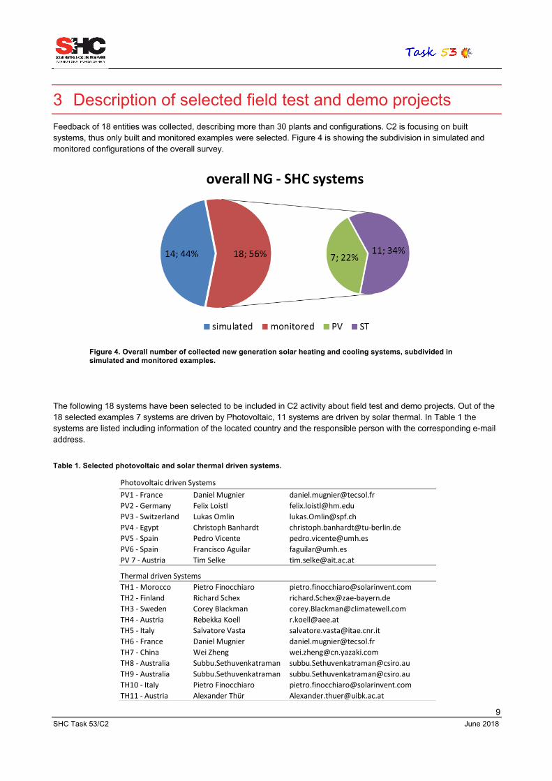
3 Description of selected field test and demo projects Feedback of 18 entities was collected, describing more than 30 plants and configurations. C2 is focusing on built systems, thus only built and monitored examples were selected. Figure 4 is showing the subdivision in simulated and monitored configurations of the overall survey.
The following 18 systems have been selected to be included in C2 activity about field test and demo projects. Out of the 18 selected examples 7 systems are driven by Photovoltaic, 11 systems are driven by solar thermal. In Table 1 the systems are listed including information of the located country and the responsible person with the corresponding e-mail address.
Table 1. Selected photovoltaic and solar thermal driven systems.
PV1 - France Daniel Mugnier [email protected] - Germany Felix Loistl [email protected] - Switzerland Lukas Omlin [email protected] - Egypt Christoph Banhardt [email protected] - Spain Pedro Vicente [email protected] - Spain Francisco Aguilar [email protected] 7 - Austria Tim Selke [email protected]
TH1 - Morocco Pietro Finocchiaro [email protected] - Finland Richard Schex [email protected] - Sweden Corey Blackman [email protected] - Austria Rebekka Koell [email protected] - Italy Salvatore Vasta [email protected] - France Daniel Mugnier [email protected] - China Wei Zheng [email protected] - Australia Subbu.Sethuvenkatraman [email protected] - Australia Subbu.Sethuvenkatraman [email protected] - Italy Pietro Finocchiaro [email protected] - Austria Alexander Thür [email protected]
Photovoltaic driven Systems
Thermal driven Systems
Figure 4. Overall number of collected new generation solar heating and cooling systems, subdivided in simulated and monitored examples.
10 SHC Task 53/C2 June 2018
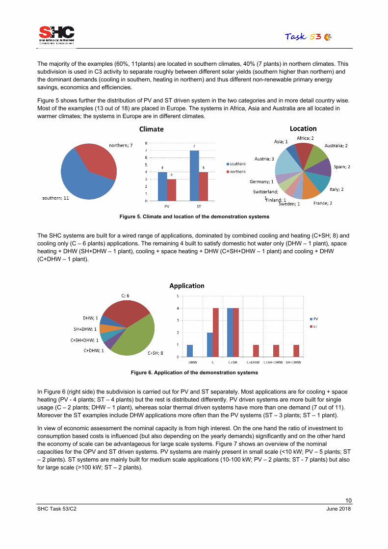
The majority of the examples (60%, 11plants) are located in southern climates, 40% (7 plants) in northern climates. This subdivision is used in C3 activity to separate roughly between different solar yields (southern higher than northern) and the dominant demands (cooling in southern, heating in northern) and thus different non-renewable primary energy savings, economics and efficiencies.
Figure 5 shows further the distribution of PV and ST driven system in the two categories and in more detail country wise. Most of the examples (13 out of 18) are placed in Europe. The systems in Africa, Asia and Australia are all located in warmer climates; the systems in Europe are in different climates.
Figure 5. Climate and location of the demonstration systems
The SHC systems are built for a wired range of applications, dominated by combined cooling and heating (C+SH; 8) and cooling only (C – 6 plants) applications. The remaining 4 built to satisfy domestic hot water only (DHW – 1 plant), space heating + DHW (SH+DHW – 1 plant), cooling + space heating + DHW (C+SH+DHW – 1 plant) and cooling + DHW (C+DHW – 1 plant).
Figure 6. Application of the demonstration systems
In Figure 6 (right side) the subdivision is carried out for PV and ST separately. Most applications are for cooling + space heating (PV - 4 plants; ST – 4 plants) but the rest is distributed differently. PV driven systems are more built for single usage (C – 2 plants; DHW – 1 plant), whereas solar thermal driven systems have more than one demand (7 out of 11). Moreover the ST examples include DHW applications more often than the PV systems (ST – 3 plants; ST – 1 plant).
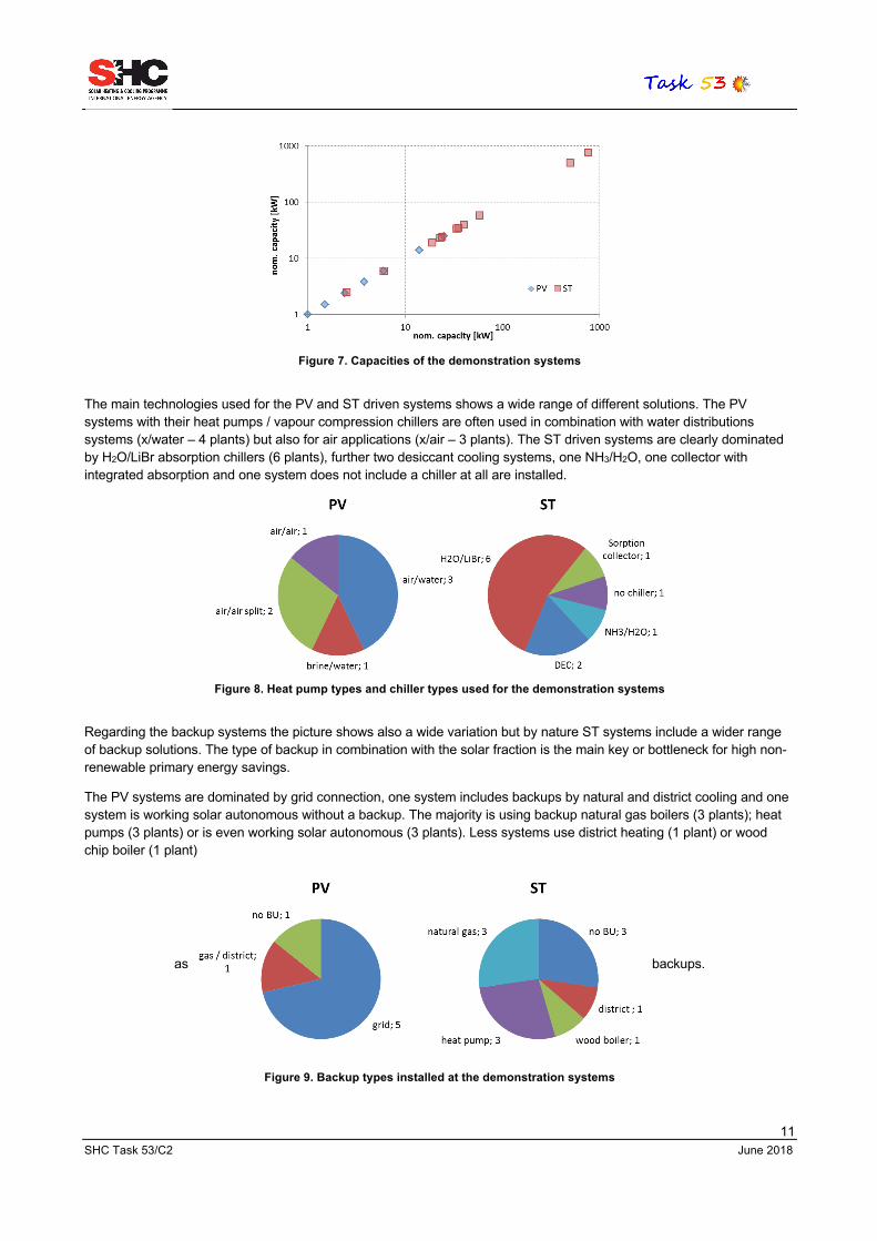
In view of economic assessment the nominal capacity is from high interest. On the one hand the ratio of investment to consumption based costs is influenced (but also depending on the yearly demands) significantly and on the other hand the economy of scale can be advantageous for large scale systems. Figure 7 shows an overview of the nominal capacities for the OPV and ST driven systems. PV systems are mainly present in small scale (<10 kW; PV – 5 plants; ST – 2 plants). ST systems are mainly built for medium scale applications (10-100 kW; PV – 2 plants; ST - 7 plants) but also for large scale (>100 kW; ST – 2 plants).
11 SHC Task 53/C2 June 2018
Figure 7. Capacities of the demonstration systems
The main technologies used for the PV and ST driven systems shows a wide range of different solutions. The PV systems with their heat pumps / vapour compression chillers are often used in combination with water distributions systems (x/water – 4 plants) but also for air applications (x/air – 3 plants). The ST driven systems are clearly dominated by H2O/LiBr absorption chillers (6 plants), further two desiccant cooling systems, one NH3/H2O, one collector with integrated absorption and one system does not include a chiller at all are installed.
Figure 8. Heat pump types and chiller types used for the demonstration systems
Regarding the backup systems the picture shows also a wide variation but by nature ST systems include a wider range of backup solutions. The type of backup in combination with the solar fraction is the main key or bottleneck for high non-renewable primary energy savings.
The PV systems are dominated by grid connection, one system includes backups by natural and district cooling and one system is working solar autonomous without a backup. The majority is using backup natural gas boilers (3 plants); heat pumps (3 plants) or is even working solar autonomous (3 plants). Less systems use district heating (1 plant) or wood chip boiler (1 plant)
as backups.
Figure 9. Backup types installed at the demonstration systems

12 SHC Task 53/C2 June 2018
Last but not least the storage solution is influencing the non-renewable primary effectiveness, but mainly the economics. By nature this picture shows higher variation within the PV system and less within the ST driven systems. Almost half of the PV systems are including a battery (el) as single solution (1 plant) or in combination with water (1 plant) or the building mass (1 plant). The other half is using ordinary water tanks (2 plants) or latent storages (1 plant); one system resigns to use storages at all. As expected the majority of the ST is using water storages (8 plants) but also a reasonable number is including latent storages (3 plants).
Figure 10. Storage types integrated in the demonstration systems

13 SHC Task 53/C2 June 2018
3.1 Details of the PV driven systems The following tables show detailed information about the photovoltaic driven NG-SHC systems.
General data
Number - Country: PV1 - France PV2 - Germany PV3 - Switzerland
City / region: Toulon Garching/Bavaria 6415 Arth
Company: Atisys - Neotherm - EED - Tecsol ZAE Bayern Aurelius Waldispühl
(Private Person)Year of completion: 2017 2017 2015
Type of application: Cooling for tertiary & industrial sector
Cooling and heating of an office building with laboraties
Space cooling and heating, 3-4 person household
Photovoltaic energy technology
PV modules: 5040 Wp, 18 PV modules 10000 Wp (estimated) 11055 Wp, 33 PV Modules,
Orientation/inclin: Southwest / 15 deg Southest / 30 deg East (-95) / 15 deg
Voltage: System runs at 400 Vac. 3 phase grid-connected inverter
Unit works at 400 Vac and PV is sypplyed at 656 Vcc
Compressor driven heating/cooling
Characteristics Heat Pump. Refriger: propane, R290
Air to air, 1 outdoor, 6-8 indoor units
brine water heatpump (heating)
Heating -NomCap = 25.0 kW ElecCon= 5.70 kW, COP = 4.39
NomCap = 14.1 kW ElecCon= 2.27 kW, COP = 6,2
Cooling Cap=2.38-0.76 kW (using a variable frequency drive)
NomCap = 22.4 kW, ElecCon = 5.45 kW, EER = 4.11
Freecooling with groundwater
Manufacturer Prototipe. Compressors GEA Fujitsu Zehnder; Comfobox10, Serie 5
Energy storage systems
Heat storage tank 1000 liters water/glycol mixture
Latent heat storage, to be defined
500 liters (DHW) and Building mass
Electric storage 4*150Ah, 12 V Gel No Electric Storage No Electric Storage
Heat rejection technology
Technology Air-cooled condenser, microchannel type 10.2 kW
Dry cooling heat rejection by direct condenstation, about 25 kW
Ground water cooling
Main and/or back-up heating /cooling system technology
System and control
Power compressors and auxiliary components heat pump when not PV production or elec. storage
Gas Boiler supplying hot water for heated and chilled ceilings / District Cooling: Well water (15°C/20°C)
Electrical heater, grid connected
Daniel Mugnier Felix Loistl Lukas [email protected] [email protected] [email protected]
14 SHC Task 53/C2 June 2018
General data
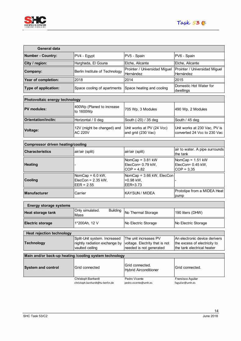
Number - Country: PV4 - Egypt PV5 - Spain PV6 - Spain
City / region: Hurghada, El Gouna Elche, Alicante Elche, Alicante
Company: Berlin Institute of Technology Prointer / Universidad Miguel Hernández
Prointer / Universidad Miguel Hernández
Year of completion: 2018 2014 2015
Type of application: Space cooling of apartments Space heating and cooling Domestic Hot Water for dwellings
Photovoltaic energy technology
PV modules: 400Wp (Planed to increase to 1600Wp 705 Wp, 3 Modules 490 Wp, 2 Modules
Orientation/inclin: Horizontal / 0 deg South (-20) / 35 deg South / 45 deg
Voltage: 12V (might be changed) and AC 220V
Unit works at PV (24 Vcc) and grid (230 Vac)
Unit works at 230 Vac, PV is converted 24 Vcc to 230 Vac
Compressor driven heating/cooling
Characteristics air/air (split) air/air (split) air to water. A pipe surrounds the tank
Heating -NomCap = 3.81 kW ElecCon= 0.79 kW, COP = 4,82
NomCap = 1.51 kW ElecCon= 0.45 kW, COP = 3,35
CoolingNomCap = 6.0 kW, ElecCon = 2.35 kW, EER = 2.55
NomCap = 3.66 kW, ElecCon =0.98 kW, EER=3.73
-
Manufacturer Carrier KAYSUN / MIDEA Prototipe from a MIDEA Heat pump
Energy storage systems
Heat storage tank Only simulated. Building Mass No Thermal Storage 190 liters (DHW)
Electric storage 1*200Ah, 12 V No Electric Storage No Electric Storage
Heat rejection technology
TechnologySplit-Unit system. Increased nightly radiation exchange by vaulted ceiling
The unit increases PV voltage. Electrity that is not needed is not generated
An electronic device derivers the excess of electricity to the tank electrical heater
Main and/or back-up heating /cooling system technology
System and control Grid connected Grid connected. Hybrid Airconditioner Grid connected.
Christoph Banhardt Pedro Vicente Francisco [email protected] [email protected] [email protected]
15 SHC Task 53/C2 June 2018
General data
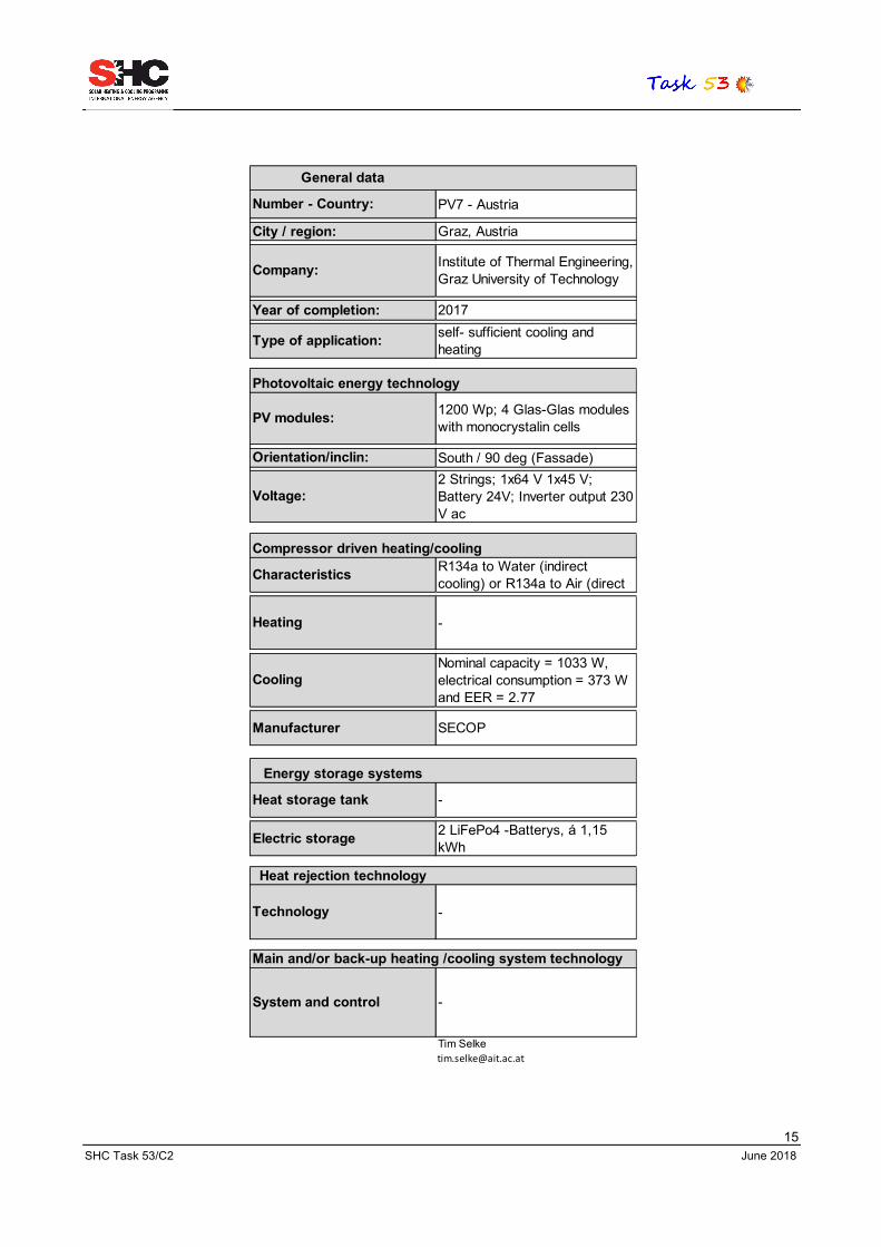
Number - Country: PV7 - Austria
City / region: Graz, Austria
Company: Institute of Thermal Engineering, Graz University of Technology
Year of completion: 2017
Type of application: self- sufficient cooling and heating
Photovoltaic energy technology
PV modules: 1200 Wp; 4 Glas-Glas modules with monocrystalin cells
Orientation/inclin: South / 90 deg (Fassade)
Voltage:2 Strings; 1x64 V 1x45 V; Battery 24V; Inverter output 230 V ac
Compressor driven heating/cooling
Characteristics R134a to Water (indirect cooling) or R134a to Air (direct
Heating -
CoolingNominal capacity = 1033 W, electrical consumption = 373 W and EER = 2.77
Manufacturer SECOP
Energy storage systems
Heat storage tank -
Electric storage 2 LiFePo4 -Batterys, á 1,15 kWh
Heat rejection technology
Technology -
Main and/or back-up heating /cooling system technology
System and control -

16 SHC Task 53/C2 June 2018
3.2 Details of the ST driven systems The following tables show detailed information about the thermal driven NG-SHC systems.
General dataNumber - Country: TH1 - Morocco TH2 - Finland TH3 - SwedenCity / region: Marrakech Mikkeli, ♁61°42′N,
27°16′O Karlstad
Company: Agence Marocaine pour l'Efficacité Energétique Savo Solar Oy ClimateWell
Year of completion: 2016 2016 2014 (Renovation Ongoing)
Type of application: Ventilation of a library Solar Cooling and Heating of an office building
Cooling & Heating of Offices/Industrial Facility
Solar energy technology
Solar themal collectors Evacuated tube collectorsFlat: 9 x 2m² of Savosolar Standard + 9 x 2m² of improved foil insulated
Flat Plate Sorption Integrated Collectors
Area: 8.81 m2 36 m² (aperture area) 180 m2 (aperture area)
Orientation/inclin: South (0º) / 25º East (-90°) / 50° Southeast (-40º) / 40º
Thermally driven technology
Technology Nr 1 DEC (solid sorption material) HVAC
1 unit of Li/Br absorption chiller with heat pump mode
Triple-state absorption module into collectors
Heating Nominal capacity 4.0 kW COP=18
24 kW @ 30/40°C COP ~ 1.72 N/A
Cooling Nominal capacity 6.2 kW COP=20
10 kW @ 15/10°C COP ~ 0.72 40 kW
Manufacturer SOLARINVENT ZAE Bayern ClimateWell & Hewalex
Energy storage systems
Heat storage tank Internal latent storage (desiccant beds)
2000 liters with improved stratification device
Heat Water: 1000 liters; Cold Storage = 12.6 m3
Heat rejection technology
System Integrated wet cooling system
Dry cooling. P=24 kW at design point Dry cooling. P=50 kW
Main and/or back-up heating /cooling system technology
System No auxiliary, the system is solar autonomous
1 unit with max. 14 kW @ 85°C in summertime and 95°C in wintertime serve as backup: heat for the absorption chiller and HP
-
Pietro Finocchiaro Richard Schex Chris [email protected] [email protected] [email protected]

17 SHC Task 53/C2 June 2018
General dataNumber - Country: TH4 - Austria TH5 - Italy TH6 - FranceCity / region: Graz Palermo Montpellier, Occitanie
Company: AEE INTEC (accompanying research) Consorzio ARCA SERM
Year of completion: 2014 2016 2013
Type of application: Cooling and heating for house + process heat/cold
Poligenerative CSP Plant to drive a 23kW Absorpition
DHW/cooling of offices & residentials
Solar energy technology
Solar themal collectors Flat plate collector (Ökotech HT 16,7)
Linear Fresnel Reflector, with Archimede Solar Energy absorber pipe
Double glasse flat plate collectors
Area: 100 m² 110m2 to SHC (total 730 m2)
240 m2
Orientation/inclin: South (0º) /45º South (0°) / 0° Southwest (30º) / 30°
Thermally driven technology
Technology Absorption cooling machine (ammonia/water)
Double effect Water/LiBr Absorption Chiller
Single effect absorption LiBr
Heating - 23 kW COP= 1.1; Integrated Cooling Tower
Cooling 19 kW 23 kW COP= 1.1; Integrated Cooling Tower
35 kW COP = 0.6
Manufacturer PINK (Pink Chiller PC 19) Systema (Italy); YAZAKI WFC-SC10
Energy storage systems
Heat storage tank Hot storage: 20 m³ Cold storage: 1 m³
Ternary Molten Salt Themocline Storage (400 kWh)
1500 liters (+10 m3 for DHW separated)
Heat rejection technology
System Dry cooling. Table top cooler (P=50 kW)
The absorption chiller is equipped with a cooling tower, in the same cabinet
JACIR SH08-3C26 - 86 kW (hybrid dry/adiabatic)
Main and/or back-up heating /cooling system technology
System Wood chip boiler (100 kW)
SCH System works using as back-up and integration system a preinstalled HP, that provide hot/cold water to the ARCA's HVAC system
Gas burners (700 kW) Compression chiller (scroll) : 900 kW
Rebekka Koell Salvatore Vasta Daniel [email protected] [email protected] [email protected]

18 SHC Task 53/C2 June 2018
General dataNumber - Country: TH7 - China TH8 - Australia TH9 - AustraliaCity / region: Jinan City, Shandong Echuca Victoria Echuca Victoria
Company: Jinan Quancheng Park Emergency Center Echuca Regional Health Echuca Regional Health
Year of completion: 2016, completion 2010 2017
Type of application: Solar heating and cooling Cooling of Building Cooling of Building
Solar energy technology
Solar themal collectorsEvacuated tube collector (heat pipe, horizontal type & gravity type)
144 Greenland Systems GLX100-16
242 Number of Chromasun MCT micro Concentrator Fresnel
Area: 160 m2 (146 m2 Horizontal type; 14 m2 Gravity type: )
406 m² 144 collectors, 2.82 m²/coll 820.4 m2
Orientation/inclin: Hz: 0º/19º; Gr: West(90)/? North / 36.5º (Australia) North / 23º (Australia)Approx 320kW @
Thermally driven technology
Technology Water fired absortion chiller, 1 unit
Broad BYDH43 Single Stage Absorption Chiller
Thermax 2-Stage Vapour Abs. Chiller HDG.40B.TCU
Heating None No Heating No Heating
Cooling 35.2 kW COP = 0.7
Cooling 500kW. Chiller power Input 2.7kW
1500 kW, Max Heat 767kW. Chiller power input
Manufacturer YAZAKI Broad Thermax
Energy storage systems
Heat storage tank Hot Water Storage: 5000 L; Cold storage: 1500 L
Hot Water Storage 2 x 5000 liters (Tank @ 90°C)
Storage Tanks for Fire Water - 150kL x 2 - Chilled Water @ approx 6°C
Heat rejection technology
System Wet cooling: P=93.3 kW Dry cooling: P=1170 kW Wet cooling: P=3527 kW
Dry cooling: P=1170 kW Wet cooling: P=3527 kW
Main and/or back-up heating /cooling system technology
System
Air-water heatpump, 1 unit, cooling 29.3 kW, heating 41 kW. Pre-cooling and pre-heating for ventilation system
Gas Boiler (steam to water) Broad HW Boost Riello RS130 - 1600kW
Wei Zheng Subbu.Sethuvenkatraman [email protected] [email protected] [email protected]

19 SHC Task 53/C2 June 2018
General dataNumber - Country: TH10 - Italy TH11-AustriaCity / region: Palermo Innsbruck, Austria
Company: University of Palermo/ENEA NHT
Year of completion: 2014 2015
Type of application: Ventilation of an office heating, DHW + free cooling
Solar energy technology
Solar themal collectors PVT (ventilated PV+air collector) flat plate & PV
Area: 2.4 m2 75 m² & 25 kWp
Orientation/inclin: South (0º) / 25º 20° / 40° & +20/-20° / 40°
Thermally driven technology
Technology Nr 1 DEC (solid sorption material) HVAC -
Heating Nominal capacity 2.5 kW COP=16.7 -
Cooling Nominal capacity 1.5 kW COP=25 -
Manufacturer SOLARINVENT -
Energy storage systems
Heat storage tank Internal latent storage (desiccant beds) 1 tank, 6m³
Heat rejection technology
System Integrated wet cooling system -
Main and/or back-up heating /cooling system technology
System No auxiliary, the system is solar autonomous
1 ground water heat pump (CTA: Optiheat 1-44e Duo) just for heating and DHW; no cooling mode! P_th=58 kW, P_el=9.8kW, COP=6.0 at W10/W35
Pietro Finocchiaro Alexander Thü[email protected] [email protected]

20 SHC Task 53/C2 June 2018
4 Conclusions This document describes the characteristics of 18 new generation solar cooling and heating systems – 7 New Generation (NG) photovoltaic driven systems and 11 New Generation (NG) thermally driven systems.
These systems were selected to be examples of field test and demo projects. The systems are fully monitored and will provide the needed data to calculate the performances of the systems (Subtask C3).
5 IEA SHC Technology Collaboration Programme The Solar Heating and Cooling Technology Collaboration Programme was founded in 1977 as one of the first multilateral technology initiatives ("Implementing Agreements") of the International Energy Agency. Its mission is “to enhance collective knowledge and application of solar heating and cooling through international collaboration to reach the goal set in the vision of solar thermal energy meeting 50% of low temperature heating and cooling demand by 2050.
The members of the IEA SHC collaborate on projects (referred to as “Tasks”) in the field of research, development, demonstration (RD&D), and test methods for solar thermal energy and solar buildings.
Research topics and the associated Tasks in parenthesis include:
Solar Space Heating and Water Heating (Tasks 14, 19, 26, 44, 54) Solar Cooling (Tasks 25, 38, 48, 53) Solar Heat for Industrial or Agricultural Processes (Tasks 29, 33, 49, 62) Solar District Heating (Tasks 7, 45, 55) Solar Buildings/Architecture/Urban Planning (Tasks 8, 11, 12, 13, 20, 22, 23, 28, 37, 40, 41, 47, 51, 52, 56, 59) Solar Thermal & PV (Tasks 16, 35, 60) Daylighting/Lighting (Tasks 21, 31, 50, 61) Materials/Components for Solar Heating and Cooling (Tasks 2, 3, 6, 10, 18, 27, 39) Standards, Certification, and Test Methods (Tasks 14, 24, 34, 43, 57) Resource Assessment (Tasks 1, 4, 5, 9, 17, 36, 46) Storage of Solar Heat (Tasks 7, 32, 42, 58)
In addition to our Task work, other activities of the IEA SHC include our:
• International Conference on Solar Heating and Cooling for Buildings and Industry • Solar Heat Worldwide report – annual statistics publication • Memorandum of Understanding – working agreement with solar thermal trade organizations • Workshops and seminars
Country Members Australia, Austria, Belgium, Canada, China, Denmark, European Commission, France, Germany, Italy, Mexico, Netherlands, Norway, Portugal, Slovakia, South Africa, Spain, Sweden, Switzerland, Turkey, and United Kingdom Sponsor Members European Copper Institute, ECREEE, RCREEE, International Solar Energy Society