catalogue central gas supply systems for … · gce central gas systems 6 | central gas systemsˆ...
TRANSCRIPT

GCE CENTRAL GAS SYSTEMS
CATALOGUE CENTRAL GAS SUPPLY SYSTEMS FOR MEDICAL GASES

THE GCE BUSINESSGCE has almost 100 years of experience in the manufacture and supply of high pressure gas equipment. During this time the GCE product range has increased dramatically. Today´s product portfolio fits a large variety of applications, from simple pressure regulators and blowpipes for cutting and welding to highly sophisticated gas supply systems for the medical, electronic and analytical industries.
GCE GROUP INCLUDES FOUR BUSINESS AREAS:
• Cutting & Welding Technologies• Valves• Healthcare • Druva
ORIGINSThe origins of GCE (Gas Control Equipment) go back to the start of the 20th century when Gas Welding was first invented. The GCE group was formed as an independent company in 1987 through the merging of two of the worlds leading gas and welding companies into one independent unit. GCE has grown rapidly since its establishment and is leading the restructuring of the European gas equipment industry through mergers and acquisitions. Through its extensive Research and Development programs GCE has set standards that have become the benchmark for the whole industry.
GCE SERVICESThe main industrial customers for GCE are wholesalers and local distributors. However in some markets GCE distributes equipment with the full cooperation of the main gas supplier for that market.For these companies GCE provides both commercial and technical support. A significant part of the sales volume in this area also comes from key end user accounts such as shipyards, repair shops, OEM customers and welding machine manufacturers.
GCE DRUVASpecialty, industrial and fuel gases are used in various industries to initiate, stabilize and avoid chemical processes and to supply the energy need for industrial processes. These gases are often provided in highly purified form and have either flammable, toxic or corrosive properties and therefore require specific gas-regulating equipment that is leak-proof and corrosion-resistant and thus does not a�ect the purity, chemical properties or composition of the given gas. Pressure regulators and valves must ensure safe discharge and transportation of gases without posing any risk to users, devices or buildings. The equipment often has to withstand inlet pressures of several hundred bars and must meet the highest expectations for flow and pressure stability.
Specialty-gas regulators and valves are produced from materials such as stainless steel, brass or other metallic alloys. Proper surface treatment and coating, leak-proof connection technology and gas-resistant seals are the key elements of specialty-gas systems. These systems discharge gas locally or distribute it through pipelines to points of use in facilities and laboratories operating in the chemical, petrochemical, pharmaceutical and other industries.
GCE Druva has been a leader in field of specialty-gas equipment since 1967. With production and service centres in Germany, the Czech Republic and China, GCE’s High Purity Division is one of the market leaders in providing system components, solutions and services for specialty, high-purity and fuel gases to engineers, designers, distributors and end-users in all corners of the globe.

GCE CENTRAL GAS SYSTEMS
Druva MED Central Gas Systems | 1
GAS MANIFOLDS AND STABILIZERS . . . . . . . . . . . . . . . . . . . . . . . . . 2
GAS MANIFOLD MC25 . . . . . . . . . . . . . . . . . . . . . . . . . . . . . . . . . . . . . . . . 2
GAS MANIFOLD MM40 - HP UNIT . . . . . . . . . . . . . . . . . . . . . . . . . . . . . . 4
LINE REGULATOR . . . . . . . . . . . . . . . . . . . . . . . . . . . . . . . . . . . . . . . . . . . . 6
GAS MANIFOLD MM40 - STABILIZER . . . . . . . . . . . . . . . . . . . . . . . . . . . . 7
GAS MANIFOLD MM90 - HP UNIT FULLY AUTOMATIC . . . . . . . . . . . . 8
GAS MANIFOLD MM90 - HP UNIT . . . . . . . . . . . . . . . . . . . . . . . . . . . . . . 9
GAS MANIFOLD MM90 - STANDBY (BACKUP) . . . . . . . . . . . . . . . . . . 10
GAS MANIFOLD DUPLEX (MC80) . . . . . . . . . . . . . . . . . . . . . . . . . . . . . . . 11
GAS MANIFOLD MC80 - STABILIZER . . . . . . . . . . . . . . . . . . . . . . . . . . . 13
GAS MANIFOLD MC150 - STABILIZER . . . . . . . . . . . . . . . . . . . . . . . . . . 14
GAS MANIFOLD SIMPLEX MMR . . . . . . . . . . . . . . . . . . . . . . . . . . . . . . . 15
HIGH PRESSURE GAS MANIFOLD ACCESSORIES . . . . . . . . . . . . . 16
COLLECTION PIPE LINE . . . . . . . . . . . . . . . . . . . . . . . . . . . . . . . . . . . . . . 16
HIGH PRESSURE HOSES . . . . . . . . . . . . . . . . . . . . . . . . . . . . . . . . . . . . . . 16
CONNECTING PIPES FOR CYLINDER MANIFOLDS . . . . . . . . . . . . . . .17
CYLINDER RETAINING BRACKETS . . . . . . . . . . . . . . . . . . . . . . . . . . . . . .17
CONNECTION PIPES FOR CYLINDER PACK MANIFOLDS . . . . . . . . .17
EXTENSION PIPES . . . . . . . . . . . . . . . . . . . . . . . . . . . . . . . . . . . . . . . . . . . .17
GAS EVACUATION VALVE KIT . . . . . . . . . . . . . . . . . . . . . . . . . . . . . . . . . .17
CONNECTING COMPONENTS FOR CYLINDER MANIFOLDS . . . . . 18
NON-RETURN VALVES FOR CONNECTION PIPES . . . . . . . . . . . . . . . 18
HIGH PRESSURE FILTER . . . . . . . . . . . . . . . . . . . . . . . . . . . . . . . . . . . . . . 18
HIGH PRESSURE VALVES 300 BAR . . . . . . . . . . . . . . . . . . . . . . . . . . . . 18
GAS SIGNS . . . . . . . . . . . . . . . . . . . . . . . . . . . . . . . . . . . . . . . . . . . . . . . . . . 19
PRESSURE RELIEVE VALVE MEDICAL PIPELINE SYSTEMS . . . . . . . 20
PRESSURE MONITOR, PRESSURE WATCH,
GAS ALARMS AND VALVES. . . . . . . . . . . . . . . . . . . . . . . . . . . . . . . . . 21
PRESSURE MONITOR. . . . . . . . . . . . . . . . . . . . . . . . . . . . . . . . . . . . . . . . . 21
PRESSURE WATCH . . . . . . . . . . . . . . . . . . . . . . . . . . . . . . . . . . . . . . . . . . . 23
SLIDE ZONE CONTROL UNITS . . . . . . . . . . . . . . . . . . . . . . . . . . . . . . . . 26
GAS ALARM - GCE TOUCH . . . . . . . . . . . . . . . . . . . . . . . . . . . . . . . . . . . . 27
PRESSURE TRANSMITTER 4-20 mA . . . . . . . . . . . . . . . . . . . . . . . . . . . . 28
GAS ALARM - MC7701 . . . . . . . . . . . . . . . . . . . . . . . . . . . . . . . . . . . . . . . . 29
GAS ALARM - G4 . . . . . . . . . . . . . . . . . . . . . . . . . . . . . . . . . . . . . . . . . . . . . 30
GAS ALARM - C44 . . . . . . . . . . . . . . . . . . . . . . . . . . . . . . . . . . . . . . . . . . . . 31
SHUT-OFF VALVE BOX DN15 . . . . . . . . . . . . . . . . . . . . . . . . . . . . . . . . . . 32
SHUT-OFF VALVE BOX DN20 . . . . . . . . . . . . . . . . . . . . . . . . . . . . . . . . . 33
MEDICAL SHUT OFF VALVES . . . . . . . . . . . . . . . . . . . . . . . . . . . . . . . . . 34
NON RETURN VALVE . . . . . . . . . . . . . . . . . . . . . . . . . . . . . . . . . . . . . . . . . 35
TERMINAL UNITS . . . . . . . . . . . . . . . . . . . . . . . . . . . . . . . . . . . . . . . . . 36
TERMINAL UNIT - MEDIUNIT (DIN) . . . . . . . . . . . . . . . . . . . . . . . . . . . . . 36
TERMINAL UNIT - MEDIUNIT (SS) . . . . . . . . . . . . . . . . . . . . . . . . . . . . . . 37
TERMINAL UNIT - MEDIUNIT (BSI) . . . . . . . . . . . . . . . . . . . . . . . . . . . . . 38
TERMINAL UNIT - MEDIUNIT (CZ) . . . . . . . . . . . . . . . . . . . . . . . . . . . . . . 39
TERMINAL UNIT - MEDIUNIT (AFNOR) . . . . . . . . . . . . . . . . . . . . . . . . . . 40
TERMINAL UNIT - MC70 (SS) . . . . . . . . . . . . . . . . . . . . . . . . . . . . . . . . . . 41
TERMINAL UNIT - AFNOR . . . . . . . . . . . . . . . . . . . . . . . . . . . . . . . . . . . . . 43
WALL AND CEILING SUPPLY UNITS . . . . . . . . . . . . . . . . . . . . . . . . . 44
BED HEAD UNITS . . . . . . . . . . . . . . . . . . . . . . . . . . . . . . . . . . . . . . . . . . . . 44
MEDICAL BEAMS . . . . . . . . . . . . . . . . . . . . . . . . . . . . . . . . . . . . . . . . . . . . 48
CEILING PENDANTS . . . . . . . . . . . . . . . . . . . . . . . . . . . . . . . . . . . . . . . . . . 50
COMPACT SPRING BALANCED ARMS . . . . . . . . . . . . . . . . . . . . . . . . . 54
ACCESSORIES FOR SUPPLY UNITS . . . . . . . . . . . . . . . . . . . . . . . . . . . . 57
IMPORTANT INFORMATION AND RECOMMENDATIONS . . . . . . . 59
CERTIFICATES . . . . . . . . . . . . . . . . . . . . . . . . . . . . . . . . . . . . . . . . . . . . 59
CONTENT

GCE CENTRAL GAS SYSTEMS
2 | Central Gas Systems ⁄ Druva MED
485
450
Note!Measurements in mm.
GAS MANIFOLDS AND STABILIZERSGAS MANIFOLD MC25The gas cylinder manifold MC25 has a capacity of 25 m3/h and is primarily intended for small and medium-sized hospitals. The gas cylinder pressure is regulated in two steps. The change-over between operating side and reserve side is made automatically without any di�erences in the operating pressure. The alarm signal comes from the pressure switches to the alarm unit. The alarm signals from the alarm unit can be forwarded directly to a monitoring desk. Function control and service can be carried out without interruption in the gas supply.
SPECIFICATIONMC25 INCLUDES THE FOLLOWING COMPONENTS:
> Gas manifold MC25 > Gas alarm including power supply > Evacuating kits for collecting pipe > Shut-o� valve for distribution line > HP filters > Collecting pipe for 2×1 cylinder
FOR A COMPLETE MC25 MANIFOLD ADD: > High pressure collecting pipe set (high pressure valves, filters and non-return valves) > High pressure hoses with safety wire > Cylinder retaining brackets (included in gas cylinder collecting pipe set) > Gas name sign
(For more information, please see accessories pages 16–20)
Item No. Denomination Gas PRV Alarm
0727315 MC25 – 2×1 O2 Manual activation C44
0727316 MC25 – 2×1 Air Manual activation C44
0727317 MC25 – 2×1 N2O, CO2 Manual activation C44
TECHNICAL DATA
Gases: O2, Air, N2, N2O, CO2, (all medical gases)
Nominal flow: 25 m3/h
Inlet nominal pressure: 200 bar (20 000 kPa)
Outlet nominal pressure: 4,5 bar (setting range 0,5–6 bar)
Intermediate nominal pressure: 12 bar (setting range 9–16 bar)
Inlet connection: W21,8×1/14"M
Outlet connection: G1/2"M + soldering piece pipe ø 10, ø 15 mm
Outlet pressure relieve valve: 6,8 bar
Intermediate pressure relieve valve: 17 bar
Pressure relieve valve pipe dimension: ø 15 mm
Regulatory status: Complies with Medical Devices Directive 93/42/EEC
Complies with EN ISO 7396-1 (Central Gas Supply Systems)
Complies with EN 60601-1-2 (Electromagnetic compatibility)
present SIS HB 370 and HTM 02-01
BASIC DIMENSIONS

GCE CENTRAL GAS SYSTEMS
Druva MED Central Gas Systems | 3
FLOW CHARTS OF MANIFOLD MC25 PRESSURE CHARACTERISTIC

GCE CENTRAL GAS SYSTEMS
4 | Central Gas Systems ⁄ Druva MED
GAS MANIFOLD MM40 - HP UNITManifold MM40 HP unit is an automatic manifold. It is working on the principal of di�erent pressures between the operation and reserve regulator. By the manual lever, the operator can decide which side will be the operational side and which will be the reserve side. When the operating side is empty, the manifold will without any action start to supply gas from the reserve side with the lower regulator pressure and fulfilll the requests to supply without interrupting the flow.MM40 HP unit manifolds together with a stabilizer should be used as second and third source of gas in systems with liquid gas tank. For hospitals without liquid gas tanks it is possible to use manifold MM40 HP unit together with a stabilizer as first and second source, and in connection with a third source (MM90 Standby) it will provide a final solution to fulfill ISO 7396-1 and national installation standards. Manifolds are supplied with an alarm system which increases safety to maximal level and informs the hospital personal about each non standard situation. Gas Alarm C44 is a standard accessory. The gas alarm C44 gives visual and audible indications.It acts as a surveillance system and sounds the alarm when the following happens:1. Leaking reserve side2. Empty position (High/Low distribution pressure when connected to a Stabilizer)3. Change operation side4. High intermediate pressure
> The gas alarm C44 is able to communicate with other equipment through relays. > The alarm has a battery back-up for 30 minutes of operation. > Manifold MM40 HP unit is only first stage of regulation and must be installed together with a Stabilizer which will stabilize the final pressure used in the hospital gas outlets.
> GCE medical manifolds are CE-marked and fulfill the ISO 7396-1 standard.
SPECIFICATIONMM40 INCLUDES THE FOLLOWING COMPONENTS:
> MM40 HP unit Manifold > Gas alarm C44 > Purge valves > HP filters > Shut-o� valve for distribution line to stabilizer
FOR A COMPLETE MM40 HP UNIT MANIFOLD ADD: > Collecting pipe set (high pressure valves, non-return valves and high pressure components) > Cylinder retaining brackets (included in gas cylinder collecting pipe set) > High pressure hoses with safety wire > Plug for close collecting pipeline > Gas name sign > Stabilizer
(For more information, please see accessories pages 16–20)
Item No. Denomination Gas PRV Alarm
0727330 MM40 – HP unit 2×1 O2, Air, N2 Standard C44
0727331 MM40 – HP unit 2×1 O2, Air, N2 Manual activation C44
0727334* MM40 – HP unit 2×1 O2, Air, N2, N2O, CO2 Standard –
0727335 MM40 – HP unit 2×1 N2O, CO2 Standard C44
0727336 MM40 – HP unit 2×1 N2O, CO2 Manual activation C44*basic version without electric sensors
TECHNICAL DATA
Gases: O2, Air, N2, N2O, CO2 (all medical gases)
Nominal flow: 40 m3/h
Inlet nominal pressure: 200 bar
Outlet nominal pressure: 12 bar (setting range 9–16 bar)
Inlet connection: W21,8×1/14"M
Outlet connection: G1/2"M + soldering piece pipe ø 10, ø 15 mm
Pressure relieve valve: 17 bar
Pressure relieve valve pipe dimension: ø 10 mm
Purge valves connection: W21,8×1/14"M
Regulatory status:
Complies with Medical Devices Directive 93/42/EEC
Complies with EN ISO 7396-1 (Central Gas Supply Systems)
Complies with EN 60601-1-2 (Electromagnetic compatibility)
present SIS HB 370 and HTM 02-01

GCE CENTRAL GAS SYSTEMS
Druva MED Central Gas Systems | 5
FLOW CHART OF MANIFOLD MM40 PRESSURE CHARACTERISTIC
BASIC DIMENSIONS
Note!Measurements in mm.
365
455

GCE CENTRAL GAS SYSTEMS
6 | Central Gas Systems ⁄ Druva MED
LINE REGULATORA stabilizer is a pressure reduction unit with the task to equalize the eventual pressure variation in the hospital pipeline system to ensure a correct pressure from the terminal units. The stabilizer makes it possible to distribute gas with a di� erent pressure to departments and buildings in the hospital area. In some cases it is needed to deliver a higher pressure from the main gas manifold to compensate for small pipe dimensions. In those cases the Stabilizer should be mounted as close as possible before the fi rst terminal unit, to ensure a correct pressure to the patient.
SPECIFICATIONLINE REGULATOR INCLUDES THE FOLLOWING COMPONENTS:> Line regulator FOR A COMPLETE LINE REGULATOR ADD:> Plastic cover for locking> Alarm unit (included if ordered together with HP unit)
Note!Measurements in mm.
206
83
151
Item No. Denomination Gas type Inlet*
0727333 LINE REG O2, N2O, Air, CO2, N2 LH
K141621 LINE REG O2 – AFNOR LH
K141631 LINE REG O2 – AFNOR RH
K141622 LINE REG N2O – AFNOR LH
K141632 LINE REG N2O – AFNOR RH
K141623 LINE REG Air – AFNOR LH
K141633 LINE REG Air – AFNOR RH
K141629 LINE REG Air-800 – AFNOR LH
K141639 LINE REG Air-800 – AFNOR RH
K141624 LINE REG N2 – AFNOR LH
K141625 LINE REG CO2 – AFNOR LH*LH = inlet from left side; RH = inlet from right side
TECHNICAL DATA
Gases: O2, Air, Air–800, N2, N2O, CO2 (all medical gases)
Nominal fl ow: 40 m3/h
Inlet nominal pressure: 16 bar (1600 kPa)
Outlet nominal pressure: 4,5 bar (setting range 0,5–10 bar)
Inlet connection: G1/2"M + soldering piece pipe ø 12 mm
Outlet connection: G1/2"M + soldering piece pipe ø 12 mm
Pressure sensors: Optional (Pressure switches; Transmitters 0–50 mV; 4–20 mA)
Emergency QC inlet: Optional QC by national standards
Regulatory status:
Complies with Medical Devices Directive 93/42/EEC
Complies with EN ISO 7396-1 (Central Gas Supply Systems)
Complies with EN 60601-1-2 (Electromagnetic compatibility)
present HTM 02-01
BASIC DIMENSIONS

GCE CENTRAL GAS SYSTEMS
Druva MED Central Gas Systems | 7
Note!Measurements in mm.
GAS MANIFOLD MM40 – STABILIZER Manifold MM40 – STABILIZER is a second stage pressure reduction unit with the task to equalize the eventual pressure variation in the hospital pipeline system to ensure a correct pressure from the terminal units. MM40 – STABILIZER is only a second stage reduction unit where the primary gas supply is provided by high pressure gas manifolds (such as MM40 – HP Unit). In case of a signal for pressure deviation in relation to the alarm settings, the alarm can easily be displayed on a gas alarm unit. It is also possible to send information to the central operation control. The stabilizer can be delivered with either pressure transmitter 4–20 mA, pressure transmitter 0–50 mV or with pressure switches. Gas reduction unit MM40 – STABILIZER must always be installed in compliance with the standards EN ISO 7396-1 and the appropriate national standards.
SPECIFICATIONMM40 STABILIZER INCLUDES THE FOLLOWING COMPONENTS:> MM40 Stabilizer Manifold FOR A COMPLETE MM40 STABILIZER MANIFOLD ADD:> Plastic cover for locking> Alarm unit (included if ordered together with HP unit)
Item No. Denomination Gas PRV Alarm
0727329 MM40 – Stabilizer O2, N2O, Air, CO2, N2 – –
0727337 MM40 – Stabilizer Air–800 – –
0727332 MM40 – Stabilizer O2, N2O, Air, CO2, N2 Manual Activation Pressure switch
0727344 MM40 – Stabilizer O2, N2O, Air, CO2, N2 Manual Activation 4-20mA
ACCESSORIESItem No. Denomination
COM001002 Lockable cover
TECHNICAL DATA
Gases: O2, Air, Air–800, N2, N2O, CO2 (all medical gases)
Nominal fl ow: 40 m3/h
Inlet maximal pressure: 20 bar (2000 kPa)
Outlet nominal pressure: 4,5 bar (setting range 0,5–10 bar)
Inlet connection 1: G1/2"M + soldering piece pipe ø 12 mm
Inlet connection 2: Optional (G1/2"M + soldering piece pipe ø 12 mm)
Outlet connection: G1/2"M + soldering piece pipe ø 12 mm
Pressure relieve valve: Optional (6,8 bar; outlet pipe ø 15 mm)
Pressure sensors: Optional (Pressure switches; Transmitters 0–50 mV; 4–20 mA)
Emergency QC inlet: Optional QC by national standards
Regulatory status:
Complies with Medical Devices Directive 93/42/EEC
Complies with EN ISO 7396-1 (Central Gas Supply Systems)
Complies with EN 60601-1-2 (Electromagnetic compatibility)
present SIS HB 370 and HTM 02-01
BASIC DIMENSIONS230
110
290
Note!Measurements in mm.

GCE CENTRAL GAS SYSTEMS
8 | Central Gas Systems ⁄ Druva MED
455
530
760
Note!Measurements in mm.
GAS MANIFOLD MM90 - HP UNIT FULLY AUTOMATICThe MM90 HP unit medical manifold is intended for use in hospital pipeline systems as medical gas source. Together with MM90, always use an alarm providing all alarms according to standard (like gas alarm C44). As 2nd stage is recommended to use a stabilizer. The manifold will deliver gas from the operating bank to the manifold pressure regulator until the cylinders are exhausted. At that point the supply will switch to the reserve bank and the empty bank can be replenished. The object gives uninterrupted gas supply. Gas Alarm C44 is a standard accessory. The gas alarm C44 gives visual and audible indication. It surveils and the alarm sounds when the following happens:1. Change operation side/Leaking on reserve side2. High operation pressure3. Low operation pressure 4. Empty position (High/Low distribution pressure when connected to a Stabilizer)The gas alarm C44 is able to communicate with other equipment through relays. The alarm has a battery back-up for 30 minutes of operation.
SPECIFICATIONMM90 INCLUDES THE FOLLOWING COMPONENTS:
> MM90 HP unit Manifold > Gas alarm C44 > Purge valves > HP filters
FOR A COMPLETE MM90 HP UNIT MANIFOLD ADD: > Collecting pipe set (high pressure valves, and non-return valves / high pressure components) > Cylinder retaining brackets (included in gas cylinder collecting pipe set) > High pressure hoses with safety wire > Plug for close collecting pipeline > Gas name sign > Stabilizer
(For more information, please see accessories pages 16–20)
Item No. Denomination Gas PRV Alarm
0727301 MM90 – HP unit AUTO 2×1 O2 Standard C44
0727302 MM90 – HP unit AUTO 2×1 Air Standard C44
0727303 MM90 – HP unit AUTO 2×1 N2O, CO2 Standard C44
0727308* MM90 – HP unit AUTO 2×1 O2, N2O, Air, CO2, N2 Standard –
0727309 MM90 – HP unit AUTO 2×1 O2 Standard Pressure switch
0727310 MM90 – HP unit AUTO 2×1 Air Standard Pressure switch
0727311 MM90 – HP unit AUTO 2×1 N2O, CO2 Standard Pressure switch*basic version without electric sensors
TECHNICAL DATA
Gases: O2, Air, N2, N2O, CO2 (all medical gases)
Nominal flow: 90 m3/h
Inlet nominal pressure: 200 bar (20 000 kPa)
Outlet nominal pressure: 9 bar (setting range 9–15 bar)
Inlet connection: W21,8×1/14"M
Outlet connection: G3/4"F + soldering piece pipe ø 22 mm
Pressure relieve valve: 16 bar
Pressure relieve valve pipe dimension: ø 10 mm
Purge valves connection: W21,8×1/14"M + soldering piece pipe ø 10 mm
Regulatory status:
Complies with Medical Devices Directive 93/42/EEC
Complies with EN ISO 7396-1 (Central Gas Supply Systems)
Complies with EN 60601-1-2 (Electromagnetic compatibility)
present SIS HB 370 and HTM 02-01
BASIC DIMENSIONS

GCE CENTRAL GAS SYSTEMS
Druva MED Central Gas Systems | 9
455
530
760Note!Measurements in mm.
GAS MANIFOLD MM90 - HP UNITThe MM90 HP unit medical manifold is intended for use in hospital pipeline systems as medical gas source. Together with MM90, always use an alarm providing all alarms according to standard (like gas alarm C44). As 2nd stage is recommended to use a stabilizer. The manifold will deliver gas from the operating bank to the manifold pressure regulator until the cylinders are exhausted. At that point the supply will switch to the reserve bank and the exhausted bank can be replenished. The object gives uninterrupted gas supply.Gas Alarm C44 is a standard accessory. The gas alarm C44 gives a visual and audible indication. It surveils and the alarm sounds when the following happens:1. Change operation side2. Leaking on reserve side3. High operation pressure 4. Low operation pressureThe gas alarm C44 is able to communicate with other equipment through relays. The alarm has a battery back-up for 30 minutes of operation.
SPECIFICATIONMM90 INCLUDES THE FOLLOWING COMPONENTS:
> MM90 HP unit Manifold > Gas alarm C44 > Purge valves > HP filters
FOR A COMPLETE MM90 HP UNIT MANIFOLD ADD: > Collecting pipe set (high pressure valves, and non-return valves / high pressure components) > Cylinder retaining brackets (included in gas cylinder collecting pipe set) > High pressure hoses with safety wire > Plug for close collecting pipeline > Gas name sign > Stabilizer
(For more information, please see accessories pages 16–20)
Item No. Denomination Gas PRV Alarm
0727304 MM90 – HP unit 2×1 O2 Standard C44
0727305 MM90 – HP unit 2×1 Air Standard C44
0727306 MM90 – HP unit 2×1 N2O, CO2 Standard C44
0727313* MM90 – HP unit 2×1 O2, Air Manual activation MC7701
0727314* MM90 – HP unit 2×1 N2O, CO2 Manual activation MC7701
0727327** MM90 – HP unit 2×1 O2, N2O, Air, CO2, N2 Standard –*in accordance HB370; **basic version without electric sensors
TECHNICAL DATA
Gases: O2, Air, N2, N2O, CO2 (all medical gases)
Nominal flow: 90 m3/h
Inlet nominal pressure: 200 bar (20 000 kPa)
Outlet nominal pressure: 9 bar (setting range 9–15 bar)
Inlet connection: W21,8×1/14"M
Outlet connection: G3/4"F + soldering piece pipe ø 22 mm
Pressure relieve valve: 16 bar
Pressure relieve valve dimension: ø 10 mm
Purge valves connection: W21,8×1/14"M + soldering piece pipe ø 10mm
Regulatory status:
Complies with Medical Devices Directive 93/42/EEC
Complies with EN ISO 7396-1 (Central Gas Supply Systems)
Complies with EN 60601-1-2 (Electromagnetic compatibility)
present SIS HB 370 and HTM 02-01
BASIC DIMENSIONS

GCE CENTRAL GAS SYSTEMS
10 | Central Gas Systems ⁄ Druva MED
GAS MANIFOLD MM90 - STANDBY BACKUPThe manifold MM90 STANDBY is designed to be used as a third source of supply in medical central gas systems. The manifold will deliver gas when the nominal supply system pressure falls below a set level (7 bar). This is a back up source.Together with MM90 STANDBY always use the MM90 HP unit and alarm providing all alarms according to standard (like Gas alarm C44). As 2nd stage it is recommended to use a stabilizer.Gas Alarm C44 is a standard accessory. The Gas alarm C44 gives visual and audible indication. It surveils and the alarm sounds when the following happens:1. Too high outlet pressure2. Too low outlet pressure3. Empty cylinderThe Gas alarm C44 is able to communicate with other equipment through relays. The alarm has a battery back-up for 30 minutes of operation.
SPECIFICATION MM90 STANDBY INCLUDES THE FOLLOWING COMPONENTS:
> MM90 STANDBY Manifold with pressure switches > Purge valves > HP filters
245
363
318
Note!Measurements in mm.
FOR A COMPLETE MM90 STANDBY MANIFOLD ADD: > Gas alarm C44 > Collecting pipe set (high pressure valves, and non-return valves / high pressure components) > Cylinder retaining brackets (included in gas cylinder collecting pipe set) > High pressure hoses with safety wire > Plug for close collecting pipeline > Gas name sign > Stabilizer
(For more information, please see accessories pages 16–20)
Item No. Denomination Gas PRV Alarm
0727307 MM90 STANDBY O2, Air Standard Pressure switches
0727312 MM90 STANDBY N2O, CO2 Standard Pressure switches
0727338 MM90 STANDBY N2O, CO2 Manual activation Pressure switches
TECHNICAL DATA
Gases: O2, Air, N2, N2O, CO2 (all medical gases)
Nominal flow: 90 m3/h
Inlet nominal pressure: 200 bar (20 000 kPa)
Outlet nominal pressure: 7 bar (setting range 7–15 bar)
Inlet connection: W21,8×1/14"M
Outlet connection: G3/4"F + soldering piece pipe ø 22 mm
Pressure relive valve: 16 bar
Pressure relive valve pipe dimension: ø 10 mm
Purge valves connection: W21,8×1/14"M + soldering piece pipe ø 10 mm
Regulatory status:
Complies with Medical Devices Directive 93/42/EEC
Complies with EN ISO 7396-1 (Central Gas Supply Systems)
Complies with EN 60601-1-2 (Electromagnetic compatibility)
present SIS HB 370 and HTM 02-01
BASIC DIMENSIONS
GCE CENTRAL GAS SYSTEMS
Druva MED Central Gas Systems | 11
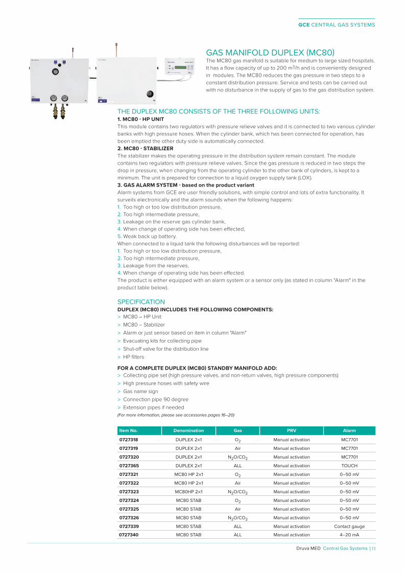
GAS MANIFOLD DUPLEX (MC80)The MC80 gas manifold is suitable for medium to large sized hospitals. It has a flow capacity of up to 200 m3/h and is conveniently designed in modules. The MC80 reduces the gas pressure in two steps to a constant distribution pressure. Service and tests can be carried out with no disturbance in the supply of gas to the gas distribution system.
THE DUPLEX MC80 CONSISTS OF THE THREE FOLLOWING UNITS:1. MC80 - HP UNIT This module contains two regulators with pressure relieve valves and it is connected to two various cylinder banks with high pressure hoses. When the cylinder bank, which has been connected for operation, has been emptied the other duty side is automatically connected.2. MC80 - STABILIZERThe stabilizer makes the operating pressure in the distribution system remain constant. The module contains two regulators with pressure relieve valves. Since the gas pressure is reduced in two steps the drop in pressure, when changing from the operating cylinder to the other bank of cylinders, is kept to a minimum. The unit is prepared for connection to a liquid oxygen supply tank (LOX).3. GAS ALARM SYSTEM - based on the product variantAlarm systems from GCE are user friendly solutions, with simple control and lots of extra functionality. It surveils electronically and the alarm sounds when the following happens:1. Too high or too low distribution pressure,2. Too high intermediate pressure,3. Leakage on the reserve gas cylinder bank,4. When change of operating side has been e�ected,5. Weak back up battery.When connected to a liquid tank the following disturbances will be reported:1. Too high or too low distribution pressure,2. Too high intermediate pressure,3. Leakage from the reserves,4. When change of operating side has been e�ected. The product is either equipped with an alarm system or a sensor only (as stated in column "Alarm" in the product table below).
SPECIFICATIONDUPLEX (MC80) INCLUDES THE FOLLOWING COMPONENTS:
> MC80 – HP Unit > MC80 – Stabilizer > Alarm or just sensor based on item in column "Alarm" > Evacuating kits for collecting pipe > Shut-o� valve for the distribution line > HP filters
FOR A COMPLETE DUPLEX (MC80) STANDBY MANIFOLD ADD: > Collecting pipe set (high pressure valves, and non-return valves, high pressure components) > High pressure hoses with safety wire > Gas name sign > Connection pipe 90 degree > Extension pipes if needed
(For more information, please see accessories pages 16–20)
Item No. Denomination Gas PRV Alarm
0727318 DUPLEX 2×1 O2 Manual activation MC7701
0727319 DUPLEX 2×1 Air Manual activation MC7701
0727320 DUPLEX 2×1 N2O/CO2 Manual activation MC7701
0727365 DUPLEX 2×1 ALL Manual activation TOUCH
0727321 MC80 HP 2×1 O2 Manual activation 0–50 mV
0727322 MC80 HP 2×1 Air Manual activation 0–50 mV
0727323 MC80HP 2×1 N2O/CO2 Manual activation 0–50 mV
0727324 MC80 STAB O2 Manual activation 0–50 mV
0727325 MC80 STAB Air Manual activation 0–50 mV
0727326 MC80 STAB N2O/CO2 Manual activation 0–50 mV
0727339 MC80 STAB ALL Manual activation Contact gauge
0727340 MC80 STAB ALL Manual activation 4–20 mA

GCE CENTRAL GAS SYSTEMS
12 | Central Gas Systems ⁄ Druva MED
TECHNICAL DATA
Gases: O2, Air, N2, N2O, CO2 (all medical gases)
Nominal flow: 200 m3/hTECHNICAL DATA - HIGH PRESSURE UNIT MC80
Inlet nominal pressure: 200 bar (20 000 kPa)
Outlet nominal pressure: 12 bar (setting range 10–16 bar)
Inlet connection: W21,8×1/14"M
Outlet connection: G3/4"F
Pressure relieve valve: 17 bar
Pressure relieve valve pipe dimension: ø 10 mm
Purge valves connection: W21,8×1/14"M + pipe ø 15 mmTECHNICAL DATA - STABILIZER MC80
Inlet maximal pressure: 20 bar (2000 kPa)
Outlet nominal pressure: 4,5 bar (setting range 0,5–6 bar)
Inlet connection: G3/4"F
Outlet connection: G3/4"F
Pressure relieve valve: 6,8 bar
Pressure relieve valve pipe dimension: ø 15 mm
Regulatory status:
Complies with Medical Devices Directive 93/42/EEC
Complies with EN ISO 7396-1 (Central Gas Supply Systems)
Complies with EN 60601-1-2 (Electromagnetic compatibility)
present SIS HB 370 and HTM 02-01
BASIC DIMENSIONS
FLOW CHART: SET MC80 - STABILIZER + MC80 - HP UNIT
Note!Measurements in mm.
FLOW CHART: MC80 - HP UNIT
580
450
450
580

GCE CENTRAL GAS SYSTEMS
Druva MED Central Gas Systems | 13
TECHNICAL DATA
Gases: O2, Air, N2, N2O, CO2 (all medical gases)
Nominal flow: 200 m3/hTECHNICAL DATA - HIGH PRESSURE UNIT MC80
Inlet nominal pressure: 200 bar (20 000 kPa)
Outlet nominal pressure: 12 bar (setting range 10–16 bar)
Inlet connection: W21,8×1/14"M
Outlet connection: G3/4"F
Pressure relieve valve: 17 bar
Pressure relieve valve pipe dimension: ø 10 mm
Purge valves connection: W21,8×1/14"M + pipe ø 15 mmTECHNICAL DATA - STABILIZER MC80
Inlet maximal pressure: 20 bar (2000 kPa)
Outlet nominal pressure: 4,5 bar (setting range 0,5–6 bar)
Inlet connection: G3/4"F
Outlet connection: G3/4"F
Pressure relieve valve: 6,8 bar
Pressure relieve valve pipe dimension: ø 15 mm
Regulatory status:
Complies with Medical Devices Directive 93/42/EEC
Complies with EN ISO 7396-1 (Central Gas Supply Systems)
Complies with EN 60601-1-2 (Electromagnetic compatibility)
present SIS HB 370 and HTM 02-01
BASIC DIMENSIONS
FLOW CHART: SET MC80 - STABILIZER + MC80 - HP UNIT
GAS MANIFOLD MC80 - STABILIZERManifold MC80 – STABILIZER is a second stage pressure reduction unit with the task to equalize the eventual pressure variation in the hospital pipeline system to ensure a correct pressure from the terminal units. MC80 – STABILIZER is only second stage reduction unit where the primary gas supply is provided by high pressure gas manifolds (such as MC80, MM90 or liquid oxygen tank (LOX). When there is a signal for pressure deviation in relation to the alarm settings, the alarm can easily be displayed on a gas alarm unit. It is also possible to send information to the central operation control. The stabilizer can be delivered with a pressure transmitter 4–20 mA, a pressure transmitter 0–50 mV or with a contact gauge.The gas reduction unit MC80 – STABILIZER must always be installed in compliance with the standards EN ISO 7396-1 and the appropriate national standards.
SPECIFICATIONMC80 STABILIZER INCLUDES THE FOLLOWING COMPONENTS:
> MC80 Stabilizer ManifoldFOR A COMPLETE MC80 STABILIZER MANIFOLD ADD:
> Alarm unit (included if ordered together with HP unit) > Ball valve DN15 with welding adaptors
Item No. Denomination Gas PRV Alarm
0727324 MC80 STAB O2 Manual activation 0–50 mV
0727325 MC80 STAB Air Manual activation 0–50 mV
0727326 MC80 STAB N2O, CO2 Manual activation 0–50 mV
0727339 MC80 STAB ALL Manual activation Contact gauge
0727340 MC80 STAB ALL Manual activation 4–20 mA
TECHNICAL DATA
Gases: O2, Air, N2, N2O, CO2 (all medical gases)
Nominal flow: 200 m3/h
Inlet maximal pressure: 20 bar (2000 kPa)
Outlet nominal pressure: 4,5 bar (setting range 0,5–6 bar)
Inlet connection: G3/4"F
Outlet connection: G3/4"F
Pressure relieve valve: 6,8 bar
Pressure relieve valve pipe dimension: ø 15 mm
Regulatory status:
Complies with Medical Devices Directive 93/42/EEC
Complies with EN ISO 7396-1 (Central Gas Supply Systems)
Complies with EN 60601-1-2 (Electromagnetic compatibility)
present SIS HB 370 and HTM 02-01
Note!Measurements in mm.
580
450
BASIC DIMENSIONS

GCE CENTRAL GAS SYSTEMS
14 | Central Gas Systems ⁄ Druva MED
GAS MANIFOLD MC150 - STABILIZER
830
600
Note!Measurements in mm.
MC150 - STABILIZER is a second stage pressure reduction unit with the task to equalize the eventual pressure variation in the hospital pipeline system to ensure a correct pressure from the terminal units. MC150 - STABILIZER is a second stage reduction unit where the primary gas supply is provided by high pressure gas manifolds (such as MC80, MM90 or liquid oxygen tank (LOX). When there is a signal for pressure deviation in relation to the alarm settings, the alarm can easily be displayed on a Gas alarm unit. It is also possible to send information to the central operation control. The stabilizer can be delivered with either pressure transmitter 4-20 mA, pressure transmitter 0-50 mV or with contact gauge.The gas reduction unit MC150 - STABILIZER must always be installed in compliance with the standards EN ISO 7396-1 and the appropriate national standards.
SPECIFICATIONMC150 STABILIZER INCLUDES THE FOLLOWING COMPONENTS:> MC150 Stabilizer ManifoldFOR A COMPLETE MC150 STABILIZER MANIFOLD ADD:> Alarm unit (included if ordered together with HP unit)
Item No. Denomination Gas PRV Alarm
325397706 MC150 STAB O2 Manual activation Contact gauge
325397707 MC150 STAB O2, Air, N2 Manual activation 4-20 mA
TECHNICAL DATA
Gases: O2, Air, N2, N2O, CO2 (all medical gases)
Nominal fl ow: 360 m3/h
Inlet maximal pressure: 20 bar (2000 kPa)
Outlet nominal pressure: 4,5 bar (setting range 0,5–6 bar)
Inlet connection: 2× G1 1/2"F+soldering piece pipe ø 35 mm
Outlet connection: 2× G1 1/2"F+soldering piece pipe ø 35 mm
Pressure relieve valve: 6,8 bar
Pressure relieve valve pipe dimension: ø 35 mm
Regulatory status:
Complies with Medical Devices Directive 93/42/EEC
Complies with EN ISO 7396-1 (Central Gas Supply Systems)
Complies with EN 60601-1-2 (Electromagnetic compatibility)
present SIS HB 370 and HTM 02-01
BASIC DIMENSIONS
GCE CENTRAL GAS SYSTEMS
Druva MED Central Gas Systems | 15
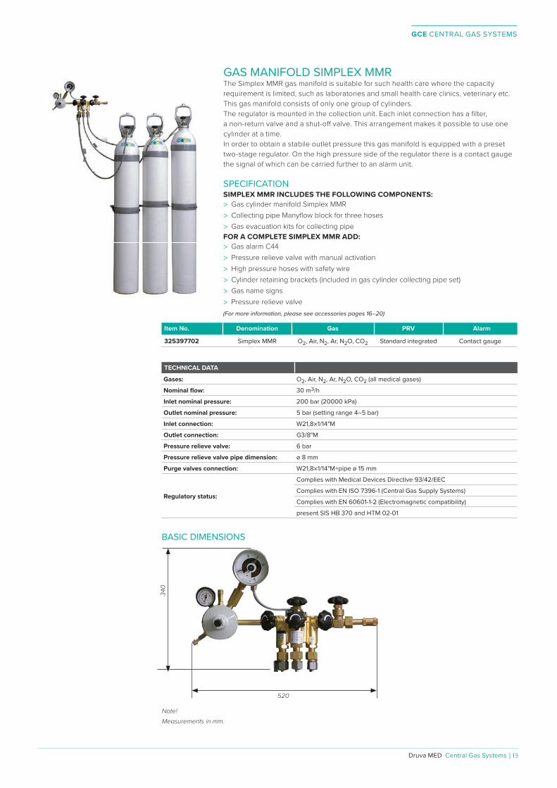
GAS MANIFOLD SIMPLEX MMRThe Simplex MMR gas manifold is suitable for such health care where the capacity requirement is limited, such as laboratories and small health care clinics, veterinary etc. This gas manifold consists of only one group of cylinders.The regulator is mounted in the collection unit. Each inlet connection has a fi lter, a non-return valve and a shut-o� valve. This arrangement makes it possible to use one cylinder at a time.In order to obtain a stabile outlet pressure this gas manifold is equipped with a preset two-stage regulator. On the high pressure side of the regulator there is a contact gauge the signal of which can be carried further to an alarm unit.
Note!Measurements in mm.
520
340
SPECIFICATIONSIMPLEX MMR INCLUDES THE FOLLOWING COMPONENTS:> Gas cylinder manifold Simplex MMR> Collecting pipe Manyfl ow block for three hoses> Gas evacuation kits for collecting pipeFOR A COMPLETE SIMPLEX MMR ADD:> Gas alarm C44> Pressure relieve valve with manual activation> High pressure hoses with safety wire> Cylinder retaining brackets (included in gas cylinder collecting pipe set)> Gas name signs> Pressure relieve valve(For more information, please see accessories pages 16–20)
Item No. Denomination Gas PRV Alarm
325397702 Simplex MMR O2, Air, N2, Ar, N2O, CO2 Standard integrated Contact gauge
TECHNICAL DATA
Gases: O2, Air, N2, Ar, N2O, CO2 (all medical gases)
Nominal fl ow: 30 m3/h
Inlet nominal pressure: 200 bar (20000 kPa)
Outlet nominal pressure: 5 bar (setting range 4–5 bar)
Inlet connection: W21,8×1/14"M
Outlet connection: G3/8"M
Pressure relieve valve: 6 bar
Pressure relieve valve pipe dimension: ø 8 mm
Purge valves connection: W21,8×1/14"M+pipe ø 15 mm
Regulatory status:
Complies with Medical Devices Directive 93/42/EEC
Complies with EN ISO 7396-1 (Central Gas Supply Systems)
Complies with EN 60601-1-2 (Electromagnetic compatibility)
present SIS HB 370 and HTM 02-01
BASIC DIMENSIONS

GCE CENTRAL GAS SYSTEMS
16 | Central Gas Systems ⁄ Druva MED
HIGH PRESSURE GAS MANIFOLD ACCESSORIESGCE can supply a complete range of high pressure accessories making it possible to install a medical gas supply system. All accessories are designed and manufactured according to the relevant standard for high pressure systems. The high pressure pipe components are manufactured in the following materials: stainless steel AISI 316 L and brass CuZn39Pb3, and they are tested at 360 bar. Cylinder holders for cylinders and connecting pipes are manufactured in AISI 316.
HIGH PRESSURE HOSESMedical high pressure hoses are used to connect cylinders or cylinder bundles to gas supply systems. The high pressure hose is intended to be used with a pressure of up to 230 bar maximum. Pressure tested at 345 bar. The hose is equipped with a safety wire.
HANDLINGThe high pressure hose should be transported, stored, installed and maintained according to Instruction of Use. Maximum life time after installation is 5 years.
Item No. Gas Lenght (mm) Inlet connection Outlet connection
325197641 O2 1250 W21,8×1/14"RH W21,8×1/14"RH
325197651 O2 2000 W21,8×1/14"RH W21,8×1/14"RH
325197642 N2O 1250 R3/8"RH W21,8×1/14"RH
325197652 N2O 2000 R3/8"RH W21,8×1/14"RH
325197643 Air, Air–800 1250 R5/8"RH W21,8×1/14"RH
325197653 Air, Air–800 2000 R5/8"RH W21,8×1/14"RH
325197644 N2/Ar 1250 W24,32×1/14"RH W21,8×1/14"RH
325197654 N2/Ar 2000 W24,32×1/14"RH W21,8×1/14"RH
325197645 CO2 1250 W27×2"RH W21,8×1/14"RH
325197655 CO2 2000 W27×2"RH W21,8×1/14"RH
TECHNICAL DATA
Tube: Acid-proof Stainless Steel (AISI 316)
Plait: Stainless Steel (AISI 304)
Wire: Stainless Steel (AISI 304)
Nut and tightening material: Acid-proof Stainless Steel (AISI 316)
Case and Oetiker: Stainless Steel (AISI 304)
Regulatory status:
Complies with Medical Devices Directive 93/42/EEC
Complies with EN ISO 7396-1 (Central Gas Supply Systems)
Complies with EN ISO 21969 (High Pressure Flexible Connection)
COLLECTION PIPE LINECollecting pipe sets are prepared for GCE HP manifold units. These sets are increasing the inlet points for HP cylinders or bundles. It is possible to connect the collecting pipelines serially and can be used in combination.
THE SET CONTAINS:> High Pressure Valve> Non Return Valve> Collection Pipe
Item No. Denomination Application
0733003 1 cylinder collection pipe set, without cylinder holder Back up manifold
0733004 2 cylinders collection pipe set, without cylinder holder Back up manifold
0733005 4 cylinders collection pipe set, without cylinder holder Back up manifold
0733000 2×1 cylinder collection pipe set Cylinder bundles
0733001 2×2 cylinders collection pipe set Cylinder bundles
0733002 2×4 cylinders collection pipe set Cylinder bundles
0733006 2×1 cylinder collection pipe set+cylinder holders Gas cylinders
0733007 2×2 cylinders collection pipe set+cylinder holders Gas cylinders
0733008 2×4 cylinders collection pipe set+cylinder holders Gas cylinders

GCE CENTRAL GAS SYSTEMS
Druva MED Central Gas Systems | 17
CONNECTING PIPES FOR CYLINDER MANIFOLDSConnecting pipes with retaining brackets of stainless steel, for 1–4 cylinders.Item No. Connecting threads Length (mm) Number of cylinders
325197218 W21,8×1/14"RH EXT–INT 289 1
215191072 W21,8×1/14"RH EXT–INT 579 2
215191073 W21,8×1/14"RH EXT–INT 1159 4
CYLINDER RETAINING BRACKETSCylinder retaining brackets, completely made of stainless steel, for 1 or 2 cylinders.Item No. Length (mm) Number of cylinders
215191074P 260 1
215191075P 550 2
CONNECTION PIPES FOR CYLINDER PACK MANIFOLDSItem No. Connecting threads Length (mm) Number of cylinders
215191012 W21,8×1/14"RH EXT–INT 289 1
215191013 W21,8×1/14"RH EXT–INT 579 2
215191014 W21,8×1/14"RH EXT–INT 1159 4
EXTENSION PIPESItem No. Connecting threads Length (mm)
215191011 W21,8×1/14"RH EXT–INT 700
GAS EVACUATION VALVE KITItem No. Inlet connection Outlet connection pipe (mm)
325199080 W21,8×1/14" INT ø 15

GCE CENTRAL GAS SYSTEMS
18 | Central Gas Systems ⁄ Druva MED
CONNECTING COMPONENTS FOR CYLINDER MANIFOLDSItem No. Description Thread Position
215191010 Connection pipe 90° W21,8×1/14" EXT–INT 1
215191077 Blind plug W21,8×1/14" EXT 2
215191068 Adaptor W21,8×1/14" LH/ RH EXT–INT 3
200059835P Coupling nut W21,8×1/14" LH/RH INT–INT 4
215191080 End plug with nut W21,8×1/14" INT 5
215191085 T–pipe for DUPLEX W21,8×1/14" INT–INT–INT 6
215191126 S–pipe W21,8×1/14" EXT–INT 7
202502362 Aluminium washer 50 pcs 16×12,5×1,5 mm
325111032P Copper washers 10 pcs 18×12,7×1,5 mm
NON-RETURN VALVES FOR CONNECTION PIPESItem No. Denomination Inlet Outlet
215191044 Non-return valve for connection pipes W21,8×1/14"RH EXT W21,8×1/14"RH INT
HIGH PRESSURE FILTERItem No. Denomination Inlet Outlet
9459650P High pressure fi lter W21,8×1/14"RH EXT W21,8×1/14"RH INT
HIGH PRESSURE VALVES 300 BARItem No. Denomination Inlet Outlet
0765001 SOV DN4 W21,8×1/14"RH W21,8×1/14"LH
Item No. Denomination Inlet Outlet
BV777097 BV300 DN8 W21,8×1/14"RH W21,8×1/14"RH
1 2 3 4 5 67
GCE CENTRAL GAS SYSTEMS
Druva MED Central Gas Systems | 19
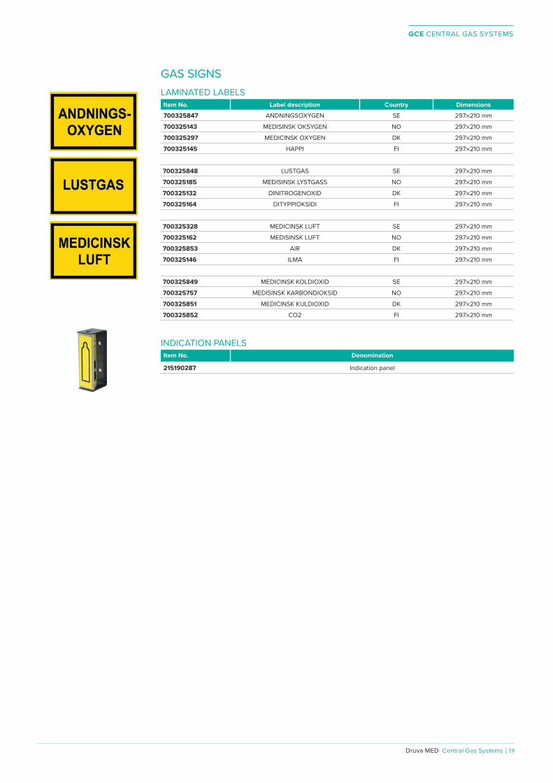
GAS SIGNSLAMINATED LABELSItem No. Label description Country Dimensions700325847 ANDNINGSOXYGEN SE 297×210 mm
700325143 MEDISINSK OKSYGEN NO 297×210 mm
700325297 MEDICINSK OXYGEN DK 297×210 mm
700325145 HAPPI FI 297×210 mm
700325848 LUSTGAS SE 297×210 mm
700325185 MEDISINSK LYSTGASS NO 297×210 mm
700325132 DINITROGENOXID DK 297×210 mm
700325164 DITYPPIOKSIDI FI 297×210 mm
700325328 MEDICINSK LUFT SE 297×210 mm
700325162 MEDISINSK LUFT NO 297×210 mm
700325853 AIR DK 297×210 mm
700325146 ILMA FI 297×210 mm
700325849 MEDICINSK KOLDIOXID SE 297×210 mm
700325757 MEDISINSK KARBONDIOKSID NO 297×210 mm
700325851 MEDICINSK KULDIOXID DK 297×210 mm
700325852 CO2 FI 297×210 mm
INDICATION PANELSItem No. Denomination
215190287 Indication panel

GCE CENTRAL GAS SYSTEMS
20 | Central Gas Systems ⁄ Druva MED
PRESSURE RELIEVE VALVE MEDICAL PIPELINE SYSTEMSThe pressure relieve valve is used in medical pipeline systems to ensure that the pressure does not exceed 6,8 bar. The pressure relieve valve should be mounted on outgoing pipelines on Simplex MMR or can be mounted on other pipelines. PRESSURE RELIEVE VALVE TUBE MOUNTINGItem No. Gas Relief Pressure Inlet connection Outlet connection
325197387 Medical gases and Air 6,8 bar G3/4"F G3/4"F
PRESSURE RELIEVE VALVE SIMPLEX MMR MOUNTINGItem No. Gas Relief Pressure Inlet connection Outlet connection
325197306 Medical gases and Air 6,8 bar G3/8"F G3/4"F
TECHNICAL DATA
Evacutaion flow: 200 m3/h
Evacutaion outlet pipe: ø 15 mm
Relief pressure: 6,8 bar
Material: brass, copper, stainless steel, rubber
Pressure class: PN16
Regulatory status:Degreased for Oxygen use
no CE-marking
GCE CENTRAL GAS SYSTEMS
Druva MED Central Gas Systems | 21
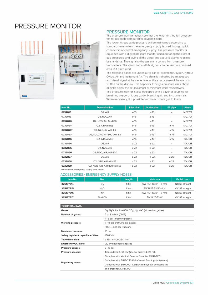
PRESSURE MONITORThe pressure monitor makes sure that the lower distribution pressure for nitrous oxide compared to oxygen is kept. The lower nitrous oxide pressure will be maintained according to standards even when the emergency supply is used through quick connectors or central emergency supply. The pressure monitor is equipped with a digital pressure monitor unit monitoring the current gas pressures, and giving all the visual and acoustic alarms required by standards. The signal to the gas alarm comes from pressure transmitters. The visual and audible signals can be sent to a manned area, if it is required.The following gases are under surveillance: breathing Oxygen, Nitrous Oxide, Air and instrument Air. The alarm is indicated by an acoustic and visual signal at the same time as the exact cause of the alarm is written on the display. This happens if the gas pressure rises above or sinks below the set maximum or minimum limits respectively. The pressure monitor is also equipped with a bayonet coupling for breathing oxygen, nitrous oxide, breathing air, and instrument air. When necessary, it is possible to connect spare gas to these.
Item No. Denomination Inlet pipe Outlet pipe ES pipe Alarm
0732818 O2, AIR ø 15 ø 15 – MC7701
0732819 O2, N2O, AIR ø 15 ø 15 – MC7701
0732820 O2, N2O, Air, Air–800 ø 15 ø 15 – MC7701
0732821* O2, AIR with ES ø 15 ø 15 ø 15 MC7701
0732822* O2, N2O, Air with ES ø 15 ø 15 ø 15 MC7701
0732823* O2, N2O, Air, Air–800 with ES ø 15 ø 15 ø 15 MC7701
0732846 O2, AIR with ES ø 15 ø 15 ø 15 TOUCH
0732854 O2, AIR ø 22 ø 22 – TOUCH
0732855 O2, N2O, AIR ø 22 ø 22 – TOUCH
0732856 O2, N2O, AIR, AIR-800 ø 22 ø 22 – TOUCH
0732857 O2, AIR ø 22 ø 22 ø 22 TOUCH
0732858 O2, N2O, AIR with ES ø 22 ø 22 ø 22 TOUCH
0732859 O2, N2O, AIR, AIR-800 with ES ø 22 ø 22 ø 22 TOUCH*With central emergency supply from below
ACCESSORIES - EMERGENCY SUPPLY HOSESItem No. Gas Length Inlet conn. Outlet conn.
325197814 O2 1,3 m SW NUT G3/8" – 6 mm QC SS straight
325197815 N2O 1,3 m SW NUT G3/8" – LH QC SS straight
325197816 Air 1,3 m SW NUT G3/8" – 8 mm QC SS straight
325197817 Air–800 1,3 m SW NUT G3/8" QC SS straight
TECHNICAL DATA
Gases: O2, N2O, Air, Air–800, CO2, N2, VAC (all medical gases)
Number of gases: 2 to 4 valves (DN15)
Working pressure:
4–5 bar (breathing gases)
7–10 bar (instrumental gases)
(-0,4)–(-0,9) bar (vacuum)
Maximum pressure: 16 bar
Safety regulator capacity at 3 bar: 150 l/min
Tube dimension: ø 15×1 mm, ø 22×1 mm
Emergency QC inlets: QC by national standards
Pressure gauges: 0–16 bar
Pressure sensors: Transmitters 0–50 mV (special order); 4–20 mA
Regulatory status:
Complies with Medical Devices Directive 93/42/EEC
Complies with EN ISO 7396-1 (Central Gas Supply Systems)
Complies with EN 60601-1-2 (Electromagnetic compatibility)
and present SIS HB 370
PRESSURE MONITOR

GCE CENTRAL GAS SYSTEMS
22 | Central Gas Systems ⁄ Druva MED
WALL
Pressure drop test. Inlet pressure 5 bar. Standard - input - output pipe, variants with ES.
Pressure drop test. Inlet pressure 5 bar. Emergency QC inlets.
BASIC DIMENSIONS
4 VALVE BOX SURFACE MOUNTEDSEEN FROM ABOVE
PRESSURE MONITOR – PRESSURE DROP CHARACTERISTIC
WALL
Note!Measurements in mm.
4 VALVE BOX RECESSEDSEEN FROM ABOVE
GCE CENTRAL GAS SYSTEMS
Druva MED Central Gas Systems | 23
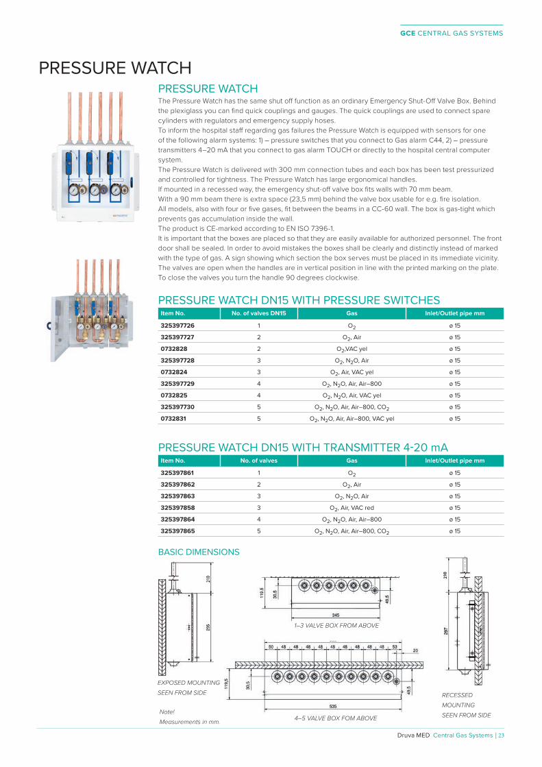
PRESSURE WATCHThe Pressure Watch has the same shut o� function as an ordinary Emergency Shut-O� Valve Box. Behind the plexiglass you can fi nd quick couplings and gauges. The quick couplings are used to connect spare cylinders with regulators and emergency supply hoses.To inform the hospital sta� regarding gas failures the Pressure Watch is equipped with sensors for one of the following alarm systems: 1) – pressure switches that you connect to Gas alarm C44, 2) – pressure transmitters 4–20 mA that you connect to gas alarm TOUCH or directly to the hospital central computer system. The Pressure Watch is delivered with 300 mm connection tubes and each box has been test pressurized and controlled for tightness. The Pressure Watch has large ergonomical handles.If mounted in a recessed way, the emergency shut-o� valve box fi ts walls with 70 mm beam. With a 90 mm beam there is extra space (23,5 mm) behind the valve box usable for e.g. fi re isolation. All models, also with four or fi ve gases, fi t between the beams in a CC-60 wall. The box is gas-tight which prevents gas accumulation inside the wall.The product is CE-marked according to EN ISO 7396-1.It is important that the boxes are placed so that they are easily available for authorized personnel. The front door shall be sealed. In order to avoid mistakes the boxes shall be clearly and distinctly instead of marked with the type of gas. A sign showing which section the box serves must be placed in its immediate vicinity. The valves are open when the handles are in vertical position in line with the printed marking on the plate. To close the valves you turn the handle 90 degrees clockwise.
PRESSURE WATCH DN15 WITH PRESSURE SWITCHESItem No. No. of valves DN15 Gas Inlet/Outlet pipe mm
325397726 1 O2 ø 15
325397727 2 O2, Air ø 15
0732828 2 O2,VAC yel ø 15
325397728 3 O2, N2O, Air ø 15
0732824 3 O2, Air, VAC yel ø 15
325397729 4 O2, N2O, Air, Air–800 ø 15
0732825 4 O2, N2O, Air, VAC yel ø 15
325397730 5 O2, N2O, Air, Air–800, CO2 ø 15
0732831 5 O2, N2O, Air, Air–800, VAC yel ø 15
PRESSURE WATCH DN15 WITH TRANSMITTER 4-20 mAItem No. No. of valves Gas Inlet/Outlet pipe mm
325397861 1 O2 ø 15
325397862 2 O2, Air ø 15
325397863 3 O2, N2O, Air ø 15
325397858 3 O2, Air, VAC red ø 15
325397864 4 O2, N2O, Air, Air–800 ø 15
325397865 5 O2, N2O, Air, Air–800, CO2 ø 15
BASIC DIMENSIONS
EXPOSED MOUNTINGSEEN FROM SIDE
1–3 VALVE BOX FROM ABOVE
RECESSED MOUNTINGSEEN FROM SIDE4–5 VALVE BOX FOM ABOVE
Note!Measurements in mm.
PRESSURE WATCH

GCE CENTRAL GAS SYSTEMS
24 | Central Gas Systems ⁄ Druva MED
PRESSURE WATCH DN20 WITH PRESSURE SWITCHESItem No. No. of valves Gas Inlet/Outlet pipe mm
0732829 1 Air–800 ø 22
0732802 2 O2, Air ø 22
0732826 2 Air–800, N2O ø 22
0732830 2 O2, VAC yel ø 22
0732804 3 O2, N2O, Air ø 22
0732803 3 O2, Air, Air–800 ø 22
0732805 3 O2, Air, VAC red ø 22
0732827 3 O2, Air, VAC yel ø 22
PRESSURE WATCH DN20 WITH TRANSMITTER 4-20 mAItem No. No. of valves Gas Inlet/Outlet pipe mm
0732806 2 O2, Air ø 22
0732808 3 O2, N2O, Air ø 22
0732807 3 O2, Air, Air–800 ø 22
0732809 3 O2, Air, VAC red ø 22
PRESSURE WATCH DN20 EMERGENCY SOURCE WITH PRESSURE SWITCHESItem No. No. of valves Gas Inlet/Outlet pipe mm
0732810 2 O2, Air ø 22
0732812 3 O2, N2O, Air ø 22
0732811 3 O2, Air, Air–800 ø 22
0732813 3 O2, Air, VAC red ø 22
PRESSURE WATCH DN20 EMERGENCY SOURCE WITH TRANSMITTER 4-20 mAItem No. No. of valves Gas Inlet/Outlet pipe mm
0732814 2 O2, Air ø 22
0732816 3 O2, N2O, Air ø 22
0732815 3 O2, Air, Air–800 ø 22
0732817 3 O2, Air, VAC red ø 22

GCE CENTRAL GAS SYSTEMS
Druva MED Central Gas Systems | 25
2–3 VALVE BOX FOM ABOVE
EXPOSED MOUNTING WITHOUT EMERGENCY SOURCE SEEN FROM SIDE
RECESSED MOUNTING WITH EMERGENCY SOURCE SEEN FROM SIDE
350
296
Note!Measurements in mm.
TECHNICAL DATA
Gases: O2, N2O, Air, Air–800, CO2, N2, VAC (all medical gases)
Number of gases:(ø 15×1) 1 to 5 valves (DN15)
(ø 22×1) 1 to 3 valves (DN20)
Working pressure:
4–5 bar (breathing gases)
7–10 bar (instrumental gases)
(-0,4)–(-0,9) bar (vacuum)
Maximum pressure: 16 bar
Tube dimension:ø 15×1 mm
ø 22×1 mm
Emergency QC inlets: QC by national standards
Pressure gauges: 0–16 bar
Pressure sensors: Pressure switches; Transmitters 0–50 mV (special order); 4–20 mA
Regulatory status:
Complies with Medical Devices Directive 93/42/EEC
Complies with EN ISO 7396-1 (Central Gas Supply Systems)
present SIS HB 370 and HTM 02-01
BASIC DIMENSIONS

GCE CENTRAL GAS SYSTEMS
26 | Central Gas Systems ⁄ Druva MED
SLIDE ZONE CONTROL UNITSZone control units are used in medical gas systems to control the output pressure of the supply source to the medical equipment and patients and when necessary, to isolate between the supply source and the utilization points.The anthracite grey coloured tempered glass panel used in the SLIDE zone control unit has a chic appearance and fits in perfectly with various interior designs in hospitals.
SLIDE Zone Control Unit, the new zone service unit, is designed to reflect contemporary design with simple lines and a sophisticated rectangular shape. Because of its aluminium body structure, the product gains light weightness and has a long life term. A smooth and semi-transparent glass cover makes it easy to clean and ensures maximum hygiene. Opening up with a slide rail system the unit is space saving in corridors. Equipped with an integrated alarm system, either as LED or TOUCH variant, the unit ensures maximum functionality and is very user-friendly.The hidden lock system keeps the zone control unit safe from unwanted manipulation and can be broken in case of emergency. One spare breakable piece of the lock can be found inside the unit.The gas pressure gauges, gas names and alarms can be read without opening the front panel.The alarm interface can be reached without opening the lock and control buttons such as “test” and “mute” can be used easily.Glass stoppers are installed at 2 di�erent stages and lift the glass properly during service processes.There is a proper separation between the gas and alarm compartments. In addition to the gas cutting valves, the gas blocks have manual physical isolation units, in compliance with EN standards.Depending on request, the SLIDE may be surface or flush mounted and with or without alarm system.
TECHNICAL DATA
GAS CONTROL STRUCTURAL FEATURES
Brass monoblock body, physical separation part, oilfree - suitable to oxygen
Equipped with a ball valve, pressure switch or pressure transmitter and manometer / vacuum meter
Gas specific emergency serv. feeding inlet at output (NIST, DIN, AFNOR, BS,UNI, SS, CZ type for O2, Med.Air, Surg.Air, Vac, N2O, Entonox (O2/N2O), CO2
Gas types: Oxygen, Medical Air, Surgical Air, Vacuum, Nitrous oxide, Entonox Mix Gas (O2/N2O), Carbon dioxide
Inlet and outlet pressure: 10 bar
-1 bar (for vacuum)
Units are not intended for use in regions endangered by explosion
Units are designed for continuous operation
ORDINARY APPLIANCE
Protection Class: 1
Type of Protection: Covered Construction (IP 21)
Council Guidelines: Class llb
BASIC REGULATIONSEN ISO 7396-1
EN ISO 9170-1
GCE CENTRAL GAS SYSTEMS
Druva MED Central Gas Systems | 27
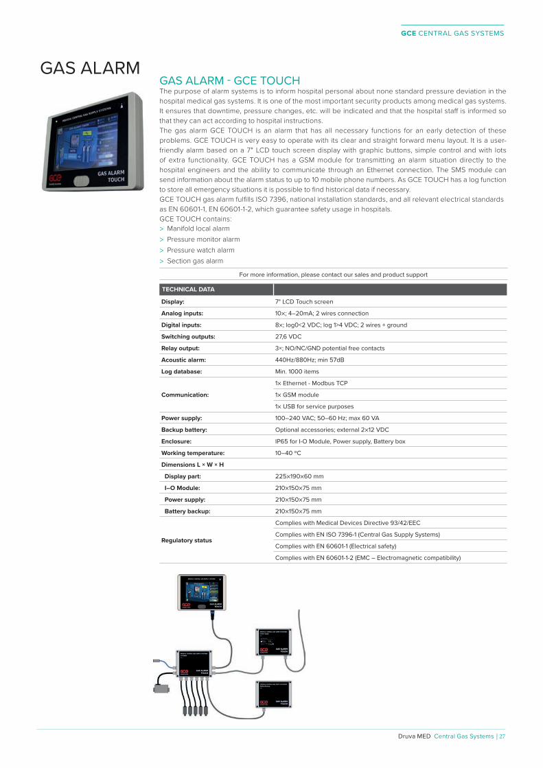
GAS ALARM - GCE TOUCH The purpose of alarm systems is to inform hospital personal about none standard pressure deviation in the hospital medical gas systems. It is one of the most important security products among medical gas systems. It ensures that downtime, pressure changes, etc. will be indicated and that the hospital sta� is informed so that they can act according to hospital instructions.The gas alarm GCE TOUCH is an alarm that has all necessary functions for an early detection of these problems. GCE TOUCH is very easy to operate with its clear and straight forward menu layout. It is a user-friendly alarm based on a 7" LCD touch screen display with graphic buttons, simple control and with lots of extra functionality. GCE TOUCH has a GSM module for transmitting an alarm situation directly to the hospital engineers and the ability to communicate through an Ethernet connection. The SMS module can send information about the alarm status to up to 10 mobile phone numbers. As GCE TOUCH has a log function to store all emergency situations it is possible to find historical data if necessary.GCE TOUCH gas alarm fulfills ISO 7396, national installation standards, and all relevant electrical standards as EN 60601-1, EN 60601-1-2, which guarantee safety usage in hospitals. GCE TOUCH contains:
> Manifold local alarm > Pressure monitor alarm > Pressure watch alarm > Section gas alarm
For more information, please contact our sales and product support
TECHNICAL DATA
Display: 7" LCD Touch screen
Analog inputs: 10×; 4–20mA; 2 wires connection
Digital inputs: 8×; log0<2 VDC; log 1>4 VDC; 2 wires + ground
Switching outputs: 27,6 VDC
Relay output: 3×; NO/NC/GND potential free contacts
Acoustic alarm: 440Hz/880Hz; min 57dB
Log database: Min. 1000 items
Communication:
1× Ethernet - Modbus TCP
1× GSM module
1× USB for service purposes
Power supply: 100–240 VAC; 50–60 Hz; max 60 VA
Backup battery: Optional accessories; external 2×12 VDC
Enclosure: IP65 for I-O Module, Power supply, Battery box
Working temperature: 10–40 ºC
Dimensions L × W × H
Display part: 225×190×60 mm
I–O Module: 210×150×75 mm
Power supply: 210×150×75 mm
Battery backup: 210×150×75 mm
Regulatory status
Complies with Medical Devices Directive 93/42/EEC
Complies with EN ISO 7396-1 (Central Gas Supply Systems)
Complies with EN 60601-1 (Electrical safety)
Complies with EN 60601-1-2 (EMC – Electromagnetic compatibility)
GAS ALARM

GCE CENTRAL GAS SYSTEMS
28 | Central Gas Systems ⁄ Druva MED
PRESSURE TRANSMITTER 4-20 mASmall compact pressure transmitter with good performance.Suitable for mobile applications when vibration reliable sensors are needed.Compact connectors.> High Proof Pressure> RoHS Compliant> All-stainless steel parts> Degreased for Oxygen
Item No. Pressure range Proof pressure Burst pressure Thread Connector
SPK36410001 (-1)-0 bar 10 bar 15 bar G1/4" EXT M12×1 - 4 pins
SPK36410002 0 - 16 bar 48 bar 640 bar G1/4" EXT M12×1 - 4 pins
SPK36410003 0–250 bar 500 bar 2500 bar G1/4" EXT M12×1 - 4 pins
ACCESSORIES Item No. Denomination Length
SPK36410004 Cable M12×1 - 4 pins 2 m
TECHNICAL DATA
Performance:
Long Term Drift: 0.2% FS/YR (non-cumulative)
Accuracy: 0.25% FS
Thermal Error: ±1.5% max, ±1% typical / 100°C
Compensated Temperatures: -40°C to +120°C
Operating Temperatures: -40°C to +120°C
Zero Tolerance: ±0.5% of span
Span Tolerance: ±0.5% of span
Fatigue Life: Designed for more than 100 M cycles
Mechanical Confi guration:
Current Output 2-wire: 4-20 mA
Supply Voltage: 8 - 30 VDC
Pressure Port: G1/4" Male
Parts in contact with gas: Stainless Steel
Electrical Connection: M12×1 - 4 pin
Enclosure: IP67
Vibration:BSEN 60068-2-6 (FC) Sine (20G);
BSEN 60068-2-64 (FH) Random (14.1 Grms)
Shock: BSEN 60068-2-27 (Ea) (50G, 11ms)
Approvals: CE, RoHS
EMC Approvals:
Emissions and Immunity tests: EN61326-1 and EN61326-2-3
WIRING DIAGRAM
1 = +IN2 = N/C3 = 0V4 = PE
ELECTRICAL CONNECTOR
1 = +INKey1
2
3
4
11 48
M12×1 - 4 pins
25
CURRENT OUTPUT MODE (LOAD RESISTOR RANGE)
Note!Measurements in mm.
BASIC DIMENSIONS
ACCESSORIES
Pin No. Wire color1 Brown2 White3 Blue4 Black

GCE CENTRAL GAS SYSTEMS
Druva MED Central Gas Systems | 29
GAS ALARM - MC7701This alarm gives visual and audible indications as well as status messages in plain language. When used with a manifold, the following conditions are surveilled:1. Too high or too low distribution pressure,2. Too high intermediate pressure,3. Leakage on the non-operating gas cylinder bank,4. When change of operating side has been e�ected.When connected to a liquid tank the following disturbances will be reported:1. Too high or too low distribution pressure,2. Too high intermediate pressure3. Leakage on the non-operating gas cylinder bank.4. When change of operating side has been e�ected. When used with a pressure monitor or pressure watch the following conditions are surveilled: Too high or too low distribution pressure. The MC7701 is able to communicate with another equipment through a serial link RS485, Modbus RTO and / or relays. The alarm has a battery back-up for 30 minutes of operation. Item No. Denomination
325197497P Digital pressure monitor MC7701 UNILARM
ACCESSORIESItem No. Denomination
325112696P Cable with Hirsman contact 3m
325112698P Cable with cable connectors 3 m
325112496 Backup batteries MC7701
325110804P Pressure Transmitter 0–50 mV G1/8" 0–16 bar
325110528P Pressure Transmitter 0–50 mV G1/8" 0–25 bar
325110527P Pressure Transmitter 0–50 mV G1/8" 0–250 bar
TECHNICAL DATA
Power supply: 230 VAC; 0,3A/24 VAC; 1,3 A
Backup battery: 10,8 V
Power Consumption: 15 VA
Enclosure: IP65
Working temperature: 10–40 ºC
Relay outputs: 14 potential free contacts
Relay output max. rating: 125 VAC; 60 VDC/1A/62,5 VA/30 W
Serial communication: Modbus RTU
Display languages: Swedish, Norwegian, Danish, Finnish, English and Hungarian
Regulatory status:
Complies with Medical Devices Directive 93/42/EEC
Complies with EN ISO 7396-1 (Central Gas Supply Systems)
EMC tested in accordance EN 60601-1-2 (Emission and immunity) BASIC DIMENSIONS
Note!Measurements in mm.
310
175
67

GCE CENTRAL GAS SYSTEMS
30 | Central Gas Systems ⁄ Druva MED
GAS ALARM - G4The alarms are summation alarms for both high and low pressure. In addition to this, a failure in the computer communication system, or a damaged signal cable (for example cut o� ) is also indicated. The loudness of the sound can be adjusted by using the potentiometer placed behind the covering lid. At delivery the sound is set at medium. The gas alarm G4 is available in two di� erent designs, for recessed mounting and for exposed mounting. The display will show any of eight languages chosen from stickers enclosed. The alarm is equipped with a rechargeable battery in case of power failure.Item No. Denomination
325197713 Gas alarm G4 recessed mounting
325197714 Gas alarm G4 exposed mounting
TECHNICAL DATA
To be used only together with digital Gas alarm - MC7701
Maximum units in serial connection: 10 units
Backup battery: 9 V
Working temperature 10-40 ºC
Power supply: From MC 7701 (15V; 4,5 VA)
Recommended cable:Signal cable 0,75 mm2
Computer wire like Alpha type 5472C or similar
Maximum cable lenght: 400 m (between alarms)
Regulatory status
Complies with Medical Devices Directive 93/42/EEC
Complies with EN ISO 7396-1 (Central Gas Supply Systems)
EMC tested in accordance EN 60601-1-2 (Emission and immunity)
EXPOSED MOUNTING
RECESSED MOUNTING
191
100 53
187
180
90 65 70
112
Cover frame
Note!Measurements in mm.
202

GCE CENTRAL GAS SYSTEMS
Druva MED Central Gas Systems | 31
GAS ALARM - C44 Gas Alarm C44 is a gas pressure alarm intended for small gas manifolds, stabilizers and for example contact gauges/pressure switches connected directly to the main line. The C44 is a microprocessor based alarm for 4 alarm channels and is connected to the pressure sensing device with volt free contacts, for example contact gauges or pressure switches. Alarm C44 is voltage fed with 11,5 VAC. Supply voltage is fed by the enclosed transformer. Visible from the front is an integrated push button TEST/MUTE. If there is no alarm condition, all the light emitting diodes and the buzzer can be tested when the button is pushed.Should there be an alarm condition, the signal will be suppressed for 15 minutes. If an alarm has been silenced and a new one occurs, the MUTE function is cleared and the signal comes back until the cause has been attended to and the MUTE button is pushed again.Alarm C44 is equipped with an environmental-friendly rechargeable NiMH back-up battery.The sound volume is adjustable via a potentiometer placed behind the cover. At delivery the sound volume is set at medium. Item No. Denomination
325197711P Gas alarm C44 exposed mounting
TECHNICAL DATA
Power supply: 230 VAC; 14VA/11,5 VAC; 0,9 A
Backup battery: 9 V
Power Consumption: about 3,5 VA
Working temperature: 10–40 ºC
Relay outputs: 4 potential free contacts
Relay output max. rating: 125 VAC; 60 VDC/1A/62,5 VA/30 W
Recommended cable:Signal cable 0,25 mm2
Feed cable 0,75 mm2
Maximum cable lenght: 3 m (alarm-pressure switches)
Regulatory status:
Complies with Medical Devices Directive 93/42/EEC
Complies with EN ISO 7396-1 (Central Gas Supply Systems)
EMC tested in accordance EN 60601-1-2 (Emission and immunity)
EXPOSED MOUNTING
191
100
53
187
Note!Measurements in mm.

GCE CENTRAL GAS SYSTEMS
32 | Central Gas Systems ⁄ Druva MED
SHUT-OFF VALVE BOX DN15Item No. Type Inlet pipe Outlet pipe
325397721 1 valve DN15 ø 15 ø 15
325397722 2 valves DN15 ø 15 ø 15
325397723 3 valves DN15 ø 15 ø 15
325397724 4 valves DN15 ø 15 ø 15
325397725 5 valves DN15 ø 15 ø 15
BASIC DIMENSIONS
For safety and service reasons a central gas system must be equipped with shut-oº valves placed so that the gas supply can easily be interrupted.The valves are mounted in a box. The emergency shut-oº valve boxes should be placed so that the gas can be shut oº section wise. This means that the boxes should be positioned before each ward, operating unit, part of ward for critical treatment and individual surgeries.The emergency shut-oº valve box is delivered with connection tubes and each box has been test pressurized and leakage tested. The emergency shut-oº valve has large ergonomical handles.If mounted in a recessed way, the emergency shut-oº valve box fi ts walls with 70 mm beam. With a 90 mm beam there is extra space (23,5 mm) behind the valve box usable for e.g. fi re isolation. All models, also with four or fi ve gases, fi t between the beams in a CC-60 wall. The box is gas-tight which prevents gas accumulation inside the wall. The product is CE–marked according to EN ISO 7396-1. It is important that the boxes are placed so that they are easily available for authorized personnel. The front door shall be sealed. In order to avoid mistakes the boxes shall be clearly and distinctly marked with the gas type. A sign showing which section the box serves must be placed in its immediate vicinity.The valves are open when the handles are in vertical position in line with the printed marking on the plate.
4–5 VALVE BOX FOM ABOVE
EXPOSED MOUNTINGSEEN FROM SIDE
RECESSED MOUNTINGSEEN FROM SIDE
1–3 VALVE BOX FROM ABOVE
Note!Measurements in mm.
SHUT-OFF VALVE BOX

GCE CENTRAL GAS SYSTEMS
Druva MED Central Gas Systems | 33
SHUT-OFF VALVE BOX DN20Item No. Type Inlet pipe Outlet pipe
0732703 1 valve DN20 ø 22 ø 22
0732701 2 valves DN20 ø 22 ø 22
0732702 3 valves DN20 ø 22 ø 22
TECHNICAL DATA
Gases: O2, N2O, Air,Air–800, CO2, N2, VAC (all medical gases)
Number of gases:(ø 15×1) 1 to 5 valves (DN15)
(ø 22×1) 1 to 3 valves (DN20)
Working pressure:
4–5 bar (breathing gases)
7–10 bar (instrumental gases)
(-0,4–(-0,9) bar (vacuum)
Maximum pressure: 16 bar
Tube dimension:ø 15×1 mm
ø 22×1 mm
Regulatory status:
Complies with Medical Devices Directive 93/42/EEC
Complies with EN ISO 7396-1 (Central Gas Supply Systems)
present SIS HB 370 and HTM 02-01
BASIC DIMENSIONS
1–3 VALVE BOX RECESSED FROM ABOVEEXPOSED MOUNTING
SEEN FROM SIDE RECESSED MOUNTINGSEEN FROM SIDE
Note!Measurements in mm.

GCE CENTRAL GAS SYSTEMS
34 | Central Gas Systems ⁄ Druva MED
MEDICAL SHUT OFF VALVES B A
A B
GCE
max. 40 bar
H
L
SHUT-OFF VALVE INCL 2 PCS WASHERItem No. Thread Valve L (mm) H(mm)
325196767 G1/2" EXT DN10 67 46
325196768 G3/4" EXT DN15 77 48
325197794 G1" EXT DN20 100 52
325196770 G1 1/4" EXT DN25 115 54
325397236 G1 1/2" EXT DN32 132 72
325397237 G2" EXT DN40 145 84
CONNECTION PARTS (2 CONNECTION NUTS AND 2 CONNECTION PIECES)Item No. Material Valve A/B mm
325196910 Red brass SS 5204 DN10 10/15
325196911 Red brass SS 5204 DN10 12
325196912 Red brass SS 5204 DN15 15/22
325196913 Red brass SS 5204 DN15 18
325197795 Red brass SS 5204 DN20 22/28
325196914 Red brass SS 5204 DN25 22/35
325196915 Red brass SS 5204 DN25 28
325197324 Red brass SS 5204 DN32 35/42
325197325P Red brass SS 5204 DN40 42/48
CONNECTION PARTS (SOLDERING ADAPTER DN40-DN50 2 PCS)Item No. Material A/B mm
325196776 Red brass SS 5204 48/54 Order both DN 40 and DN 50 for union enlargement.
SPARE PARTSItem No. Denomination Valve Thread
325110373P Washer, 10 pcs DN10 –
325100729P Washer, 10 pcs DN15 –
325113389P Washer, 10 pcs DN20 –
325100730P Washer, 10 pcs DN25 –
201241192P O–ring, EPDM, 5 pcs DN32 –
201241193P O–ring, EPDM, 5 pcs DN40 –
202502266 Connection nut, 2 pcs DN10 G1/2" INT
202502268 Connection nut, 2 pcs DN15 G3/4" INT
325113373P Connection nut, 2 pcs DN20 G1" INT
202502270 Connection nut, 2 pcs DN25 G1 1/4" INT
325112281P Connection nut, 1 pce DN40 G2" INT TECHNICAL DATA
Gases: O2, Air, N2, Ar, N2O, CO2 (all medical gases)
Material valve housing: Nickel plated brass
Ball: Chrome plated brass
Stem: Nickel plated brass
Max working pressure: 40 bar (4000 kPa)
Tighten proof: (-1)–50 bar [(-100)–5000 kPa]
Regulatory status: Complies with Medical Devices Directive 93/42/EEC
Complies with EN ISO 7396-1 (Central Gas Supply System)
Complies with EN 331 (Manually operated ball valves)
To meet safety requirements, the gas supply to operating rooms etc must be fitted with a device to allow instant shut o�. To allow maintenance the gas supply must be controlled by section. To achieve the demands of safety and maintenance, shut-o� valves should be fitted in every main line, riser and branch line in the pipework system. The valves are degreased and blown clean. They can be equipped with unions to be soldered to the copper piping. Before delivery each valve is individually leak tested. The ball is sealed with washer of PTFE. The stem is sealed with two silicon O–rings or PTFE washer. The valve housings are sealed with an EPDM quality O–ring. No maintenance – the ball valve does not need services, when necessary the whole valve is exchanged.

GCE CENTRAL GAS SYSTEMS
Druva MED Central Gas Systems | 35
NON RETURN VALVE The non return valve unit is intended for use in medical central gas systems to secure that gas does not flow back from the equipment and pipes through the central gas system. This is very important for example when technical air is taken from medical air pipes for use in laboratories. The non return valve unit consists of a non return valve (NRV) with a flow direction arrow, lockable medical shut o� valves, soldering pieces, nuts and a gasspecific medical quick coupling (QC) for medical breathing air. This design makes the NRV very easy to test. The QC can also be used for checking the pressure, doing leak tests and take gas samples. The NRV unit can also be delivered with QC for instrumental air.
For more information please contact our sales and product support
NON RETURN VALVE UNITItem No. Denomination Total Length
329000825 Non return valve unit O2 DN15 415 mm
325397676 Non return valve unit AIR DN15 415 mm
329000826 Non return valve unit Air–800 DN15 415 mm
325397677 Non return valve unit AIR DN25 505 mm
325397777 Non return valve unit Air–800 DN25 505 mm
325397678 Non return valve unit AIR DN40 932 mm
SEALING BETWEEN NON RETURN VALVE AND CONNECTING PIECEItem No. Denomination
944610218P DN15 O–ring, 10 pcs
325112713P DN25 Sealing, 10 pcs
325112880P DN40 O–ring, 10 pcs
TECHNICAL DATA
Opening pressure: 0,06 bar (6 kPa)
Pressure class: PN16
Regulatory status: Degreasing for Oxygen use
no CE–marking
GCE CENTRAL GAS SYSTEMS
36 | Central Gas Systems ⁄ Druva MED
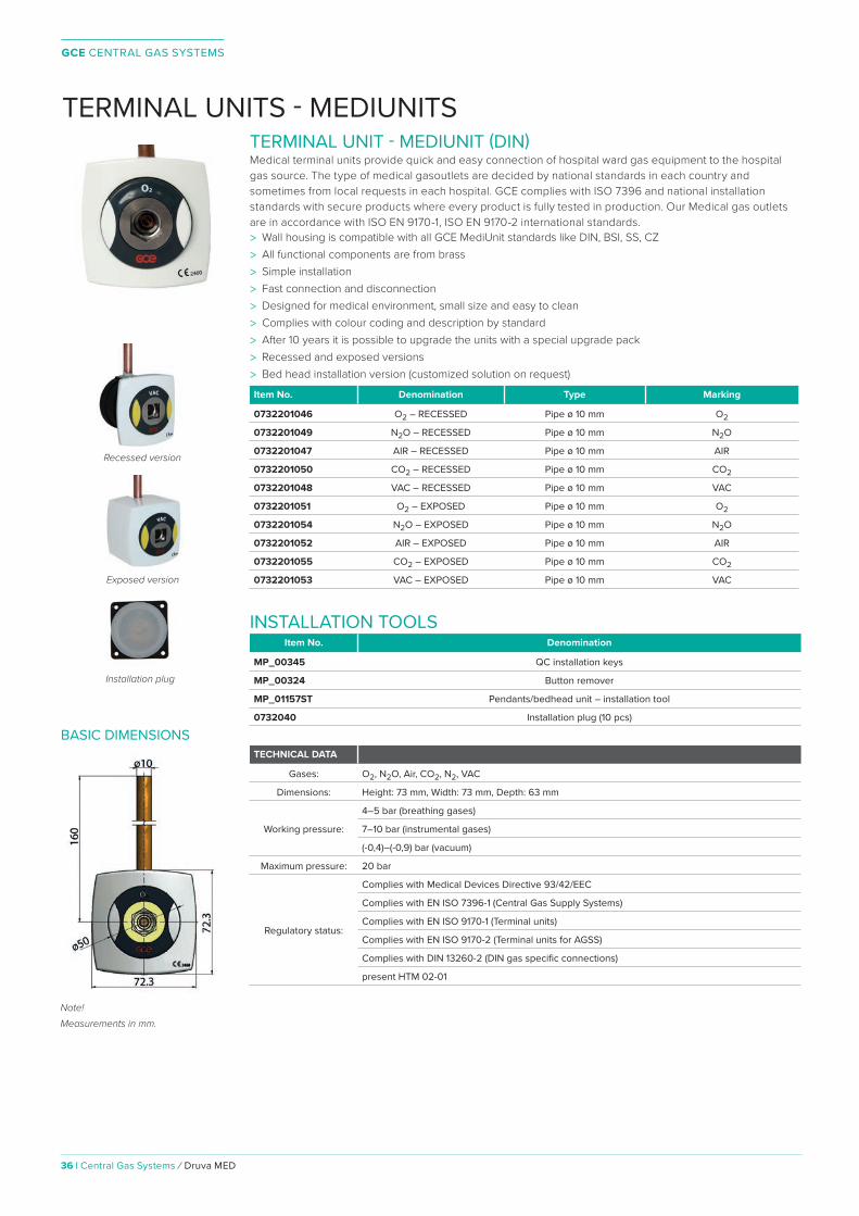
TERMINAL UNIT - MEDIUNIT (DIN)Medical terminal units provide quick and easy connection of hospital ward gas equipment to the hospital gas source. The type of medical gasoutlets are decided by national standards in each country and sometimes from local requests in each hospital. GCE complies with ISO 7396 and national installation standards with secure products where every product is fully tested in production. Our Medical gas outlets are in accordance with ISO EN 9170-1, ISO EN 9170-2 international standards.> Wall housing is compatible with all GCE MediUnit standards like DIN, BSI, SS, CZ> All functional components are from brass> Simple installation> Fast connection and disconnection> Designed for medical environment, small size and easy to clean> Complies with colour coding and description by standard> After 10 years it is possible to upgrade the units with a special upgrade pack> Recessed and exposed versions> Bed head installation version (customized solution on request)
Item No. Denomination Type Marking
0732201046 O2 – RECESSED Pipe ø 10 mm O2
0732201049 N2O – RECESSED Pipe ø 10 mm N2O
0732201047 AIR – RECESSED Pipe ø 10 mm AIR
0732201050 CO2 – RECESSED Pipe ø 10 mm CO2
0732201048 VAC – RECESSED Pipe ø 10 mm VAC
0732201051 O2 – EXPOSED Pipe ø 10 mm O2
0732201054 N2O – EXPOSED Pipe ø 10 mm N2O
0732201052 AIR – EXPOSED Pipe ø 10 mm AIR
0732201055 CO2 – EXPOSED Pipe ø 10 mm CO2
0732201053 VAC – EXPOSED Pipe ø 10 mm VAC
INSTALLATION TOOLSItem No. Denomination
MP_00345 QC installation keys
MP_00324 Button remover
MP_01157ST Pendants/bedhead unit – installation tool
0732040 Installation plug (10 pcs)
TECHNICAL DATA
Gases: O2 , N2 O, Air, CO2 , N2, VAC
Dimensions: Height: 73 mm, Width: 73 mm, Depth: 63 mm
Working pressure:
4–5 bar (breathing gases)
7–10 bar (instrumental gases)
(-0,4)–(-0,9) bar (vacuum)
Maximum pressure: 20 bar
Regulatory status:
Complies with Medical Devices Directive 93/42/EEC
Complies with EN ISO 7396-1 (Central Gas Supply Systems)
Complies with EN ISO 9170-1 (Terminal units)
Complies with EN ISO 9170-2 (Terminal units for AGSS)
Complies with DIN 13260-2 (DIN gas specifi c connections)
present HTM 02-01
Exposed version
Recessed version
Installation plug
Note!Measurements in mm.
TERMINAL UNITS - MEDIUNITS
BASIC DIMENSIONS

GCE CENTRAL GAS SYSTEMS
Druva MED Central Gas Systems | 37
TERMINAL UNIT - MEDIUNIT (SS)Medical terminal units provide quick and easy connection of hospital ward gas equipment to the hospital gas source. The type of medical gasoutlets are decided by national standards in each country and sometimes from local requests in each hospital. GCE complies with ISO 7396 and national installation standards with secure products where every product is fully tested in production. Our Medical gas outlets are in accordance with ISO EN 9170-1, ISO EN 9170-2 international standards.
> Wall housing is compatible with all GCE MediUnit standards like DIN, BSI, SS, CZ > All functional components are from brass > Simple installation > Fast connection and disconnection > Designed for medical environment, small size and easy to clean > Complies with colour coding and description by standard > After 10 years it is possible to upgrade the units with a special upgrade pack > Recessed and exposed versions > Bed head installation version (customized solution on request)
Item No. Denomination Country Type Marking
0732200073 O2 – RECESSED SE Pipe ø 10 mm ANDNINGSOXYGEN
0732200076 N2O – RECESSED SE Pipe ø 10 mm LUSTGAS
0732200074 AIR – RECESSED SE Pipe ø 10 mm ANDNINGSLUFT
0732200078 AIR-800 – RECESSED SE Pipe ø 10 mm INSTRUMENTLUFT
0732200077 CO2 – RECESSED SE Pipe ø 10 mm MEDICINSK KOLDIOXID
0732200075 VAC – RECESSED SE Pipe ø 10 mm GASUTSUG
0732200079 AGSS – RECESSED SE Pipe ø 10 mm GASUTLOPP
0732200080 O2 – EXPOSED SE Pipe ø 10 mm ANDNINGSOXYGEN
0732200083 N2O – EXPOSED SE Pipe ø 10 mm LUSTGAS
0732200081 AIR – EXPOSED SE Pipe ø 10 mm ANDNINGSLUFT
0732200085 AIR-800 – EXPOSED SE Pipe ø 10 mm INSTRUMENTLUFT
0732200084 CO2 – EXPOSED SE Pipe ø 10 mm MEDICINSK KOLDIOXID
0732200053 VAC – EXPOSED SE Pipe ø 10 mm GASUTSUG
0732200086 AGSS – EXPOSED SE Pipe ø 10 mm GASUTLOPP
For other configurations (DK, FI, NO) please contact Sales and Product Support
INSTALLATION TOOLSItem No. Denomination
MP_00345 QC installation keys
MP_00324 Button remover
MP_01157ST Pendants/bedhead unit – installation tool
0732040 Installation plug (10 pcs)
TECHNICAL DATA
Gases: O2, N2O, Air, Air–800, CO2, N2, Ar, AGSS, VAC
Dimensions: Height: 73 mm, Width: 73 mm, Depth: 63 mm
Working pressure:
4–5 bar (breathing gases)
7–10 bar (instrumental gases)
(-0,4) – (-0,9) bar (vacuum)
Maximum pressure: 20 bar
Regulatory status:
Complies with Medical Devices Directive 93/42/EEC
Complies with EN ISO 7396-1 (Central Gas Supply Systems)
Complies with EN ISO 9170-1 (Terminal units)
Complies with EN ISO 9170-2 (Terminal units for AGSS)
Complies with SS 8752430 (SS gas specific connections)
present SIS HB 370 and HTM 02-01
Recessed version
Exposed version
Installation plug
Note!Measurements in mm.
Split view
BASIC DIMENSIONS

GCE CENTRAL GAS SYSTEMS
38 | Central Gas Systems ⁄ Druva MED
TERMINAL UNIT - MEDIUNIT (BSI)Medical terminal units provide quick and easy connection of hospital ward gas equipment to the hospital gas source. The type of medical gasoutlets are decided by national standards in each country and sometimes from local requests in each hospital. GCE complies with ISO 7396 and national installation standards with secure products where every product is fully tested in production. Our Medical gas outlets are in accordance with ISO EN 9170-1, ISO EN 9170-2 international standards.> Wall housing is compatible with all GCE MediUnit standards like DIN, BSI, SS, CZ> All functional components are from brass> Simple installation> Fast connection and disconnection> Designed for medical environment, small size and easy to clean> Complies with colour coding and description by standard> After 10 years it is possible to upgrade the units with a special upgrade pack> Recessed and exposed versions> Bed head installation version (customized solution on request)
Item No. Denomination Type Marking
0732202001 O2 – RECESSED Pipe ø 10 mm O2
0732202013 N2O – RECESSED Pipe ø 10 mm N2O
0732202014 O2/N2O – RECESSED Pipe ø 10 mm O2/N2O
0732202011 AIR – RECESSED Pipe ø 10 mm AIR
0732202015 AIR-800 – RECESSED Pipe ø 10 mm AIR-800
0732202012 VAC – RECESSED Pipe ø 10 mm VAC
0732202016 O2 – EXPOSED Pipe ø 10 mm O2
0732202019 N2O – EXPOSED Pipe ø 10 mm N2O
0732202020 O2/N2O – EXPOSED Pipe ø 10 mm O2/N2O
0732202017 AIR – EXPOSED Pipe ø 10 mm AIR
0732202021 AIR-800 – EXPOSED Pipe ø 10 mm AIR-800
0732202018 VAC – EXPOSED Pipe ø 10 mm VAC
INSTALLATION TOOLSItem No. Denomination
MP_00345 QC installation keys
MP_00324 Button remover
MP_01157ST Pendants/bedhead unit – installation tool
0732040 Installation plug (10 pcs)
TECHNICAL DATA
Gases: O2 , N2 O, O2/N2 O, Air, Air-800, VAC
Dimensions: Height: 73 mm, Width: 73 mm, Depth: 63 mm
Working pressure:
4–5 bar (breathing gases)
7–10 bar (instrumental gases)
(-0,4)–(-0,9) bar (vacuum)
Maximum pressure: 20 bar
Regulatory status:
Complies with Medical Devices Directive 93/42/EEC
Complies with EN ISO 7396-1 (Central Gas Supply Systems)
Complies with EN ISO 9170-1 (Terminal units)
Complies with EN ISO 9170-2 (Terminal units for AGSS)
Complies with BS 5682 (BSI gas specifi c connections)
present HTM 02-01
Exposed version
Recessed version
Installation plug
Note!Measurements in mm.
BASIC DIMENSIONS

GCE CENTRAL GAS SYSTEMS
Druva MED Central Gas Systems | 39
TERMINAL UNIT - MEDIUNIT (CZ)Medical terminal units provide quick and easy connection of hospital ward gas equipment to the hospital gas source. The type of medical gasoutlets are decided by national standards in each country and sometimes from local requests in each hospital. GCE complies with ISO 7396 and national installation standards with secure products where every product is fully tested in production. Our Medical gas outlets are in accordance with ISO EN 9170-1, ISO EN 9170-2 international standards.> Wall housing is compatible with all GCE MediUnit standards like DIN, BSI, SS, CZ> All functional components are from brass> Simple installation> Fast connection and disconnection> Designed for medical environment, small size and easy to clean> Complies with colour coding and description by standard> After 10 years it is possible to upgrade the units with a special upgrade pack> Recessed and exposed versions> Bed head installation version (customized solution on request)
Item No. Denomination Type Marking
0732203026 O2 – RECESSED Pipe ø 10 mm O2
0732203029 N2O – RECESSED Pipe ø 10 mm N2O
0732203027 AIR – RECESSED Pipe ø 10 mm AIR
0732203030 CO2 – RECESSED Pipe ø 10 mm CO2
0732203028 VAC – RECESSED Pipe ø 10 mm VAC
0732203031 O2 – EXPOSED Pipe ø 10 mm O2
0732203034 N2O – EXPOSED Pipe ø 10 mm N2O
0732203032 AIR – EXPOSED Pipe ø 10 mm AIR
0732203035 CO2 – EXPOSED Pipe ø 10 mm CO2
0732203033 VAC – EXPOSED Pipe ø 10 mm VAC
INSTALLATION TOOLSItem No. Denomination
MP_00345 QC installation keys
MP_00324 Button remover
MP_01157ST Pendants/bedhead unit – installation tool
0732040 Installation plug (10 pcs)
TECHNICAL DATA
Gases: O2 , N2 O, Air, Air-800, CO2 , VAC
Dimensions: Height: 73 mm, Width: 73 mm, Depth: 63 mm
Working pressure:
4–5 bar (breathing gases)
7–10 bar (instrumental gases)
(-0,4)–(-0,9) bar (vacuum)
Maximum pressure: 20 bar
Regulatory status:
Complies with Medical Devices Directive 93/42/EEC
Complies with EN ISO 7396-1 (Central Gas Supply Systems)
Complies with EN ISO 9170-1 (Terminal units)
Complies with EN ISO 9170-2 (Terminal units for AGSS)
Complies with CSN 85 2762 (Czech gas specifi c connections)
present HTM 02-01
Exposed version
Recessed version
Installation plug
Note!Measurements in mm.
BASIC DIMENSIONS

GCE CENTRAL GAS SYSTEMS
40 | Central Gas Systems ⁄ Druva MED
TERMINAL UNIT - MEDIUNIT (AFNOR)Medical terminal units provide quick and easy connection of hospital ward gas equipment to the hospital gas source. The type of medical gasoutlets are decided by national standards in each country and sometimes from local requests in each hospital. GCE complies with ISO 7396 and national installation standards with secure products where every product is fully tested in production. Our Medical gas outlets are in accordance with ISO EN 9170-1, ISO EN 9170-2 international standards.> All functional components are from brass> Simple installation> Fast connection and disconnection> Air–800 with parking position> Designed for medical environment, small size and easy to clean> Complies with colour coding and description by standard> Maintenance valve with fi lter> Recessed and exposed versions> Bed head installation version (customized solution on request)
Item No. Denomination Type Marking
0732204017 O2 – RECESSED Pipe ø 10 mm O2
0732204018 N2O – RECESSED Pipe ø 10 mm N2O
0732204019 AIR – RECESSED Pipe ø 10 mm AIR
0732204020 AIR-800 – RECESSED Pipe ø 10 mm AIR-800
0732204021 CO2 – RECESSED Pipe ø 10 mm CO2
0732204022 N2 – RECESSED Pipe ø 10 mm N2
0732204023 VAC – RECESSED Pipe ø 10 mm VAC
0732204001 O2 – EXPOSED Pipe ø 10 mm O2
0732204008 N2O – EXPOSED Pipe ø 10 mm N2O
0732204003 AIR – EXPOSED Pipe ø 10 mm AIR
0732204009 AIR-800 – EXPOSED Pipe ø 10 mm AIR-800
0732204002 CO2 – EXPOSED Pipe ø 10 mm CO2
0732204010 N2 – EXPOSED Pipe ø 10 mm N2
0732204004 VAC – EXPOSED Pipe ø 10 mm VAC
0732204069 O2 – EXPOSED - LID Pipe ø 10 mm O2
0732204072 N2O – EXPOSED - LID Pipe ø 10 mm N2O
0732204070 AIR – EXPOSED - LID Pipe ø 10 mm AIR
0732204074 AIR-800 – EXPOSED - LID Pipe ø 10 mm AIR-800
0732204073 CO2 – EXPOSED - LID Pipe ø 10 mm CO2
0732204071 VAC – EXPOSED - LID Pipe ø 10 mm VAC
TECHNICAL DATA
Gases: O2 , N2 O, Air, Air–800,CO2 , N2, VAC
Dimensions: Height: 73 mm, Width: 73 mm, Depth: 63 mm
Working pressure: 4–5 bar (breathing gases)
7–10 bar (instrumental gases)
(-0,4)–(-0,9) bar (vacuum)
Maximum pressure: 20 bar
Regulatory status: Complies with Medical Devices Directive 93/42/EEC
Complies with EN ISO 7396-1 (Central Gas Supply Systems)
Complies with EN ISO 9170-1 (Terminal units)
Complies with EN ISO 9170-2 (Terminal units for AGSS)
Complies with NF S 90-116 (Afnor gas specifi c connections)
Complies with FD S 90-119 (Afnor Air-800 gas specifi c connection)
present HTM 02-01
Exposed version - with lid
Recessed version
Installation plug
Maintenance valve
Note!
Measurements in mm.
BASIC DIMENSIONS
Exposed version - without lid

GCE CENTRAL GAS SYSTEMS
Druva MED Central Gas Systems | 41
TERMINAL UNIT - MC70 (SS)GCE gas outlets type MC 70 generation are self-sealing, i.e. they close automatically when a connected apparatus is removed. The gas outlets are furnished with a quick connection valve which means that the desired apparatus can be connected or disconnected by means of a simple one-step motion. The MC 70 gas outlets may be recessed in the wall or mounted in a panel. All MC 70 gas outlets have the same design but di�erent colour codings and labels for di�erent gases and of course gas specific non-interchangeable quick connection valves. Special e�orts have been made to make the maintenance of the gas outlets as easy as possible.
> No special tools > Maintenance valve of ball-type > Few components
Furthermore the MC70 are made according to standard SS EN 8752430 for quick connections and international standard SS EN ISO 9170-1 for terminal units. This means that the gas components are non-interchangeable in every maintenance connection point. The gas outlet is delivered with separate packages for quick connection valve, valvebody, plastic cover with name plate, push-release plate etc. To make installation easier, the valve body has a tightening plug mounted for convenient pressure testing. All necessary mounting details such as brackets, screws etc. are included in the packages. Detailed instructions are also part of the delivery. When mounting the gas outlet in a recessed way the gas outlet can be mounted either in the front wall or in the rear wall, depending on which is first set up. Recessed and exposed instalation set is necessary orded separately. Item No. Denomination Type Marking
325397281 O2 – BEDHEAD Pipe ø 8 mm O2
325397282 N2O – BEDHEAD Pipe ø 8 mm N2O
325397283 AIR – BEDHEAD Pipe ø 8 mm Air
325397284 VAC – BEDHEAD Pipe ø 8 mm VAC yellow
325397285 AGSS – BEDHEAD Pipe ø 8 mm AGSS purple
325397286 AIR–800 – BEDHEAD Pipe ø 8 mm Air–800
325397287 N2 – BEDHEAD Pipe ø 8 mm N2
325397288 CO2 – BEDHEAD Pipe ø 8 mm CO2
FOR RECESSED MOUNTING ADDItem No. Denomination
325396031 Recessed installation set
FOR EXPOSED MOUNTING ADDItem No. Denomination
325396034 Exposed installation set
INSTALLATION TOOLItem No. Denomination
325197290 Combi tool
SERVICE KITItem No. Denomination
325197222 Sparepart kit

GCE CENTRAL GAS SYSTEMS
42 | Central Gas Systems ⁄ Druva MED
TECHNICAL DATA
Gases: O2, N2O, Air, Air–800, CO2, N2, Ar, AGSS, VAC
Dimensions: Diameter: 90 mm, Depth: 60 mm
Working pressure:
4–5 bar (breathing gases)
7–10 bar (instrumental gases)
(-0,4) – (-0,9) bar (vacuum)
Maximum pressure: 20 bar
Regulatory status:
Complies with Medical Devices Directive 93/42/EEC
Complies with EN ISO 7396-1 (Central Gas Supply Systems)
Complies with EN ISO 9170-1 (Terminal units)
Complies with EN ISO 9170-2 (Terminal units for AGSS)
Complies with SS 8752430 (SS gas specific connections)
present SIS HB 370
LABELS MC70Item No. Denomination Languages
548234A26760 Circular Label O2 White 85/55 TU SS –
325113069 Circular Label MEDICINSK OXYGEN White 85/55 TU SS SE
548234A26770 Circular Label N2O Blue 85/55 TU SS –
325113070 Circular Label DINITROGENOXID N2O Blue 85/55 TU SS DK
325113071 Circular Label MEDICINSK LUFT Black/White 85/55 TU SS SE
548234A26780 Circular Label Air Black/White 85/55 TU SS –
548234A37600 Circular Label Air–800 Black/White 85/55 TU SS –
325113074P Circular Label MEDICINSK KULDIOXID Grey 85/55 TU SS DK
548234A26790 Circular Label VAC Red 85/55 TU SS –
325113072 Circular Label VAC Red 85/55 TU SS DK
548234A26800 Circular Label VAC Yellow 85/55 TU SS –
548234A40850 Circular Label GASUTLOPP Blue/Brown 85/55 TU SS SE
548234A40860 Circular Label GASUDLØB Blue/Brown 85/55 TU SS DK
548234A40870 Circular Label GASSUTLØP Blue/Brown 85/55 TU SS NO
548234A40880 Circular Label KAASUJEN POISTO Blue/Brown 85/55 TU SS FI
548234A26810 Circular Label AGSS Purple 85/55 TU SS –
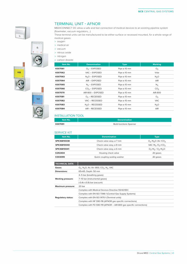
GCE CENTRAL GAS SYSTEMS
Druva MED Central Gas Systems | 43
TERMINAL UNIT - AFNORMEDICONNECT DC allow a safe and fast connection of medical devices to an existing pipeline system (fl owmeter, vacuum regulators,...)These terminal units can be manufactured to be either surface or recessed mounted, for a whole range of medical gases: > oxygen> medical air > vacuum > nitrous oxide > nitrogen > carbon dioxide
Item No. Denomination Type Marking
K007061 O2 – EXPOSED Pipe ø 10 mm O2
K007062 VAC – EXPOSED Pipe ø 10 mm Vide
K007063 N2O – EXPOSED Pipe ø 10 mm N2O
K007064 AIR – EXPOSED Pipe ø 10 mm AIR
K007065 N2 – EXPOSED Pipe ø 10 mm N2
K007066 CO2 – EXPOSED Pipe ø 10 mm CO2
K007070 AIR-800 – EXPOSED Pipe ø 10 mm AIR-800
K007081 O2 – RECESSED Pipe ø 10 mm O2
K007082 VAC – RECESSED Pipe ø 10 mm VAC
K007083 N2O – RECESSED Pipe ø 10 mm N2O
K007084 AIR – RECESSED Pipe ø 10 mm AIR
INSTALLATION TOOLItem No. Denomination
K007091 Multi-functions Spanner
SERVICE KITItem No. Denomination Type
SPK36810038 Check valve assy, ø 7 mm O2 /N2O /Air /CO2
SPK36810040 Check valve assy, ø 8 mm VAC /N2 /O2+CO2
SPK36810041 Check valve assy, ø 6 mm O2+N2 / O2+N2O
K292404 Housing check valve All gases
K303099 Quick coupling sealing washer All gases
TECHNICAL DATA
Gases: O2 , N2 O, Air, Air–800, CO2 , N2 , VAC
Dimensions: 65×65, Depth: 50 mm
Working pressure:
4–5 bar (breathing gases)
7–10 bar (instrumental gases)
(-0,4)–(-0,9) bar (vacuum)
Maximum pressure: 20 bar
Regulatory status:
Complies with Medical Devices Directive 93/42/EEC
Complies with EN ISO 7396-1 (Central Gas Supply Systems)
Complies with EN ISO 9170-1 (Terminal units)
Complies with NF S90-116 (AFNOR gas specifi c connections)
Complies with FD S90-119 (AFNOR – AIR-800 gas specifi c connections)

GCE CENTRAL GAS SYSTEMS
44 | Central Gas Systems ⁄ Druva MED
Bed head units are primarily needed in patient rooms in medical facilities. Depending on their purpose, these units are equipped with medical gas outlets, high voltage and low voltage distribution of electricity, media sockets etc. Next to standard units GCE druvaMED is able to provide customized solutions regarding design and shape to meet the special demands for delivery rooms, recovery rooms and intensive care units.Part of the bed head units may be direct, indirect or night lighting, with fl uorescent lamps or LED technology. The bed head units have a characteristic and ergonomic design that has proven itself for over more than 45 years now in medical facilities all over the world. The design can be customized to meet the overall appearance of the interior, architectural requirements and to the desires of the health care personnel. The materials used in the bed head units are designed to endure intense use and harsh conditions that can often be found in medical fi elds. This means the bed head units and available accessories are built to last and fi t for the job!
BED HEAD UNITS
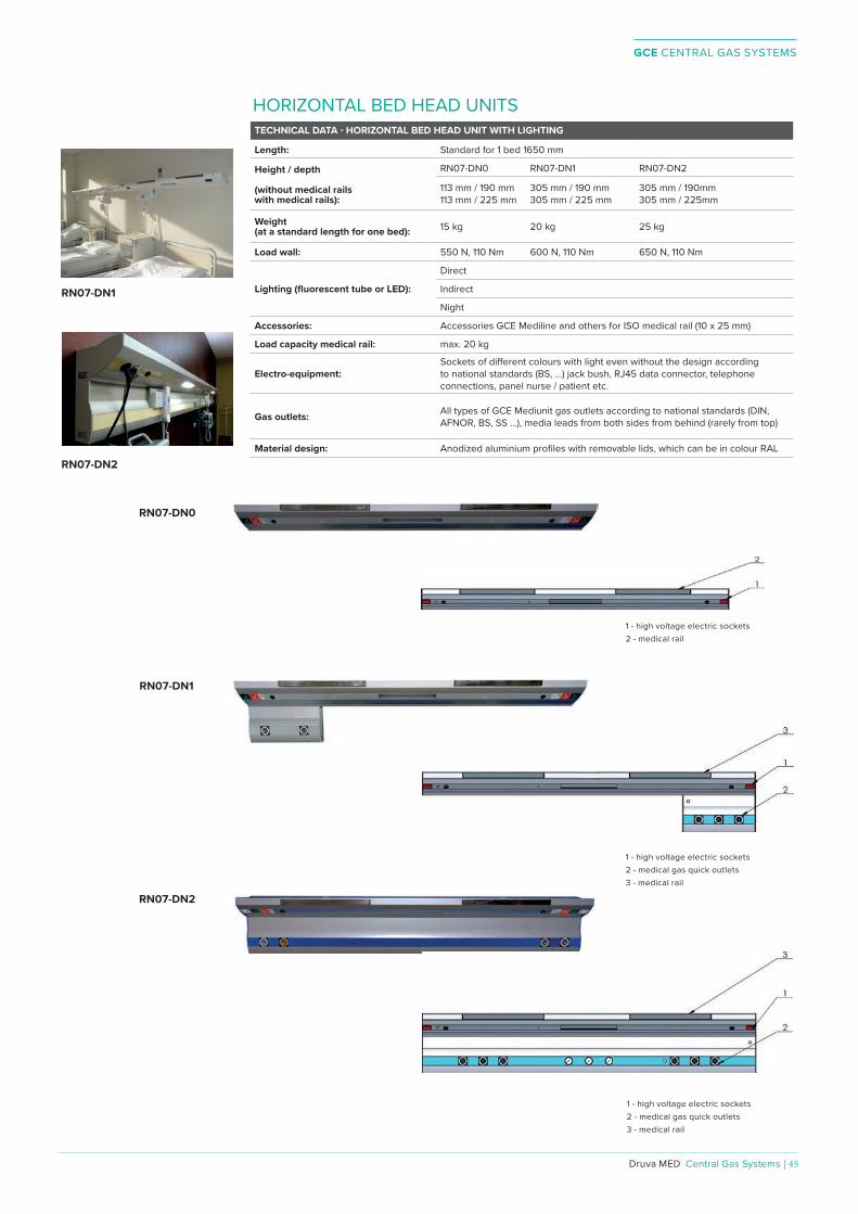
GCE CENTRAL GAS SYSTEMS
Druva MED Central Gas Systems | 45
TECHNICAL DATA - HORIZONTAL BED HEAD UNIT WITH LIGHTING
Length: Standard for 1 bed 1650 mm
Height / depth
(without medical railswith medical rails):
RN07-DN0 RN07-DN1 RN07-DN2
113 mm / 190 mm113 mm / 225 mm
305 mm / 190 mm305 mm / 225 mm
305 mm / 190mm305 mm / 225mm
Weight (at a standard length for one bed): 15 kg 20 kg 25 kg
Load wall: 550 N, 110 Nm 600 N, 110 Nm 650 N, 110 Nm
Lighting (fl uorescent tube or LED):
Direct
Indirect
Night
Accessories: Accessories GCE Mediline and others for ISO medical rail (10 x 25 mm)
Load capacity medical rail: max. 20 kg
Electro-equipment:Sockets of diº erent colours with light even without the design according to national standards (BS, ...) jack bush, RJ45 data connector, telephone connections, panel nurse / patient etc.
Gas outlets: All types of GCE Mediunit gas outlets according to national standards (DIN, AFNOR, BS, SS ...), media leads from both sides from behind (rarely from top)
Material design: Anodized aluminium profi les with removable lids, which can be in colour RAL
HORIZONTAL BED HEAD UNITS
RN07-DN0
RN07-DN1
RN07-DN2
RN07-DN2
RN07-DN1
1 - high voltage electric sockets2 - medical rail
1 - high voltage electric sockets2 - medical gas quick outlets3 - medical rail
1 - high voltage electric sockets2 - medical gas quick outlets3 - medical rail
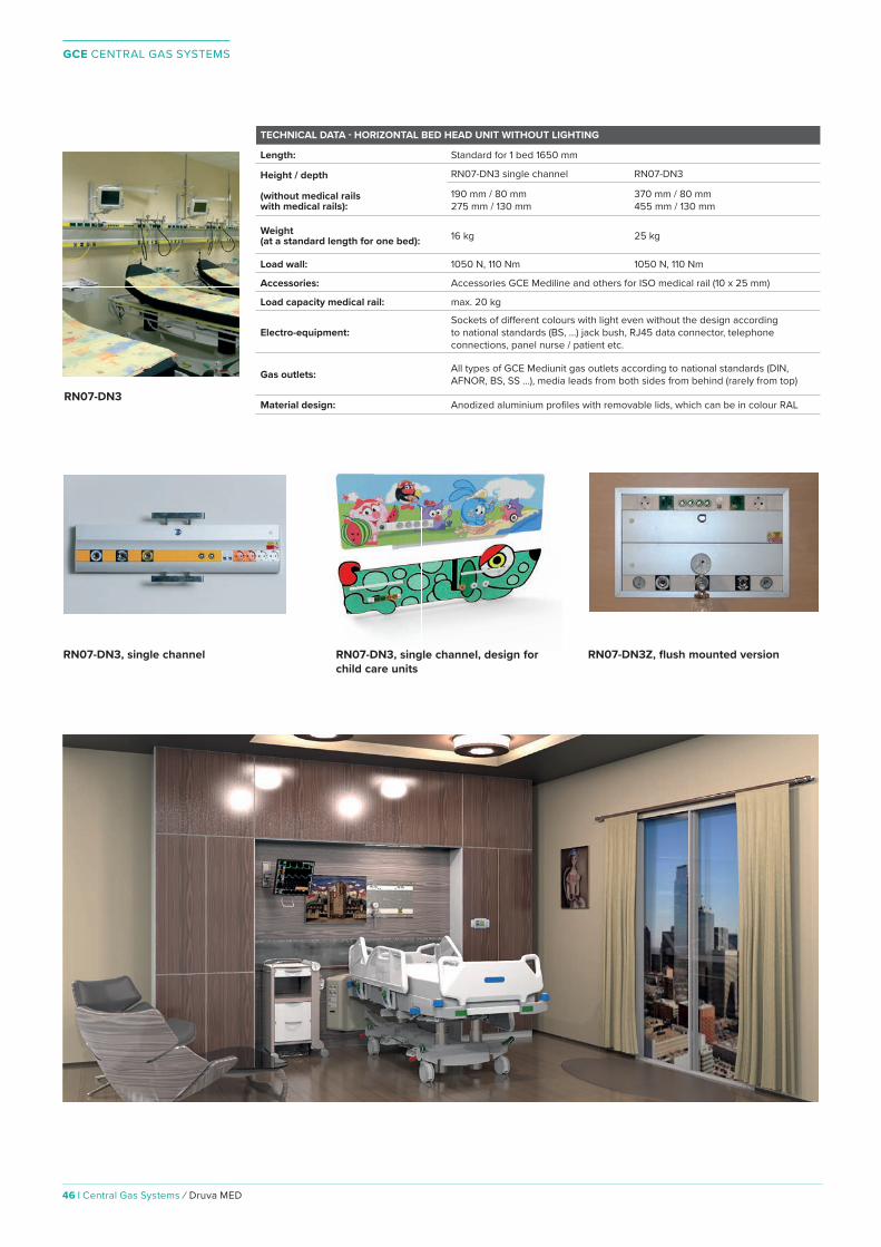
GCE CENTRAL GAS SYSTEMS
46 | Central Gas Systems ⁄ Druva MED
TECHNICAL DATA - HORIZONTAL BED HEAD UNIT WITHOUT LIGHTING
Length: Standard for 1 bed 1650 mm
Height / depth
(without medical railswith medical rails):
RN07-DN3 single channel RN07-DN3
190 mm / 80 mm275 mm / 130 mm
370 mm / 80 mm455 mm / 130 mm
Weight (at a standard length for one bed): 16 kg 25 kg
Load wall: 1050 N, 110 Nm 1050 N, 110 Nm
Accessories: Accessories GCE Mediline and others for ISO medical rail (10 x 25 mm)
Load capacity medical rail: max. 20 kg
Electro-equipment:Sockets of diº erent colours with light even without the design according to national standards (BS, ...) jack bush, RJ45 data connector, telephone connections, panel nurse / patient etc.
Gas outlets: All types of GCE Mediunit gas outlets according to national standards (DIN, AFNOR, BS, SS ...), media leads from both sides from behind (rarely from top)
Material design: Anodized aluminium profi les with removable lids, which can be in colour RAL
RN07-DN3, single channel RN07-DN3Z, flush mounted versionRN07-DN3, single channel, design for child care units
RN07-DN3
For more information and variants please contact our sales and product support

GCE CENTRAL GAS SYSTEMS
Druva MED Central Gas Systems | 47
For more information and variants please contact our sales and product support
VERTICAL BED HEAD UNITSTECHNICAL DATA - VERTICAL BED HEAD UNIT WITHOUT LIGHTING (SUPPLY COLUMNS)
Length: Standard 1000 mm
Width / depth: ZS07 ZS07L
370 mm / 150 mm 165 mm / 260 mm
Weight (at a standard length): 30 kg 45 kg
Load wall: 900 N, 200 Nm 1450 N, 1200 Nm
Accessories: Accessories GCE Mediline and others for rod *28
Load capacity stainless steel rod: max. 40 kg max. 60 kg
Electro-equipment:Sockets of diº erent colours with light even without the design according to national standards (BS, ...) jack bush, RJ45 data connector, telephone connections, panel nurse / patient etc.
Gas outlets: All types of GCE Mediunit gas outlets according to national standards (DIN, AFNOR, BS, SS ...), media leads from both sides from behind (rarely from top)
Material design: Anodized aluminium profi les with removable lids, which can be in colour RAL
ZS07LZS07
ZS071 - shelf2 - rod for shelves and other accessories3 - medical gas quick outlets4 - high voltage electric sockets

GCE CENTRAL GAS SYSTEMS
48 | Central Gas Systems ⁄ Druva MED
Medical beams are a special kind of bed head unit. Instead of attached to the wall, a medical beam is mounted to the ceiling for maximum fl exibility for patient positioning. Medical beams, like wall mounted bed head units, can be equipped with medical gas outlets and electricity supply at optimal distance to the patients bed. They are mainly used in specialized medical workplaces like CCU, ICU and operating theatres.The medical beam can be fi tted with a large range of accessories: Spot lamps placed on a medical rail, refracted arms, telescopic rods withcurtain, medical rails, positional (night) lights or other accessories depending on the needs and requirements of the workplace concerned.Thanks to its design it ensures an optimal use of space on the one hand, as well as being safe for the patient and the medical staº on the other.
MEDICAL BEAMS
For more information and variants please contact our sales and product support

GCE CENTRAL GAS SYSTEMS
Druva MED Central Gas Systems | 49
TECHNICAL DATA - MEDICAL BEAMS
Length profi le with equipmentstandard for 1 bed:
ZMP07 ZMP07 double side ZMP07 laminar
1950 mm 1950 mm 3000 mm one side
Height / depth without legs(without medical rails with medical rails):
320 mm / 280mm320 mm / 315mm
320 mm / 460mm320 mm / 530mm
320 mm / 280mm320 mm / 315mm
Length of legs: max. 2000 mm
Weight (at a standard length for one bed): max 150 kg max 175 kg max 300 kg
Load ceiling (from one leg): 5300 N, 2100 Nm 8000 N, 2100 Nm 5300 N, 2100 Nm
Lighting (fl uorescent tube or LED):
Direct
Indirect
Night
Accessories: Accessories GCE Mediline and others for ISO medical rail (10 x 25 mm) and shelving rods *28
Load capacity medical rail: max. 20 kg
Electro-equipment:Sockets of diº erent colours with light even without the design according to diº erent national standards (BS, ...) jack bush, RJ45 data connector, telephone connections and etc.
Gas outlets: All types of GCE Mediunit gas outlets according to national standards (DIN, AFNOR, BS, SS ...)
Material design: Steel with powder coating surface / Anodized aluminium profi les with removable lids, which can be in colour RAL
For more information and variants please contact our sales and product support
1 - rotary roller with shelf2 - ceiling cover3 - arms for accessories4 - suspended ceiling depth

GCE CENTRAL GAS SYSTEMS
50 | Central Gas Systems ⁄ Druva MED
CEILING PENDANTCeiling pendants are designated for supply of medical gases, electric current and low current from the ceiling to the workplace of the medical specialists. They are primarily used in operating theatres, ARD, and ICU. The rotary pendant is terminated by a source column and a removable shelf is applied as a holder of medical devices.Rotary joints combined with a horizontal and swing arm can be controlled to any intermediate position within a room using an electric drive. All the rotary joints of the arms are thereby fi tted with manually operated position interlock.
PS07 OK07-28OK07-16

GCE CENTRAL GAS SYSTEMS
Druva MED Central Gas Systems | 51
TECHNICAL DATA - CEILING PENDANTS WITH ROTARY AND HEIGHT ADJUSTABLE ARMS
Total length of arm: OK07-55 OK07-57
800 mm
1200 mm1400 mm1600 mm1800 mm
Lengthsource columnwith medical rails:
Source column A Source column L
790 mm 890 mm990 mm1090 mm
690mm1090 mm 1290 mm1590 mm
Width / Depth source column with medical rails and rods (column L):
410mm / 190mm 448 mm/ 328 mm
Weight: 205 kg 240 kg
Load ceiling: 3600 N, 3600 Nm 4000 N, 5500 Nm
Accessories: Accessories GCE Mediline and others for ISO medical rail (10 x 25 mm) and shelving rods *28
Electro-equipment:Sockets of diº erent colours with light even without the design according to national standards (BS, ...)jack bush, RJ45 data connector, telephone connections and etc.
Gas outlets: All types of GCE Mediunit gas outlets according to national standards (DIN, AFNOR, BS, SS ...)
Material designarm / source column:
Steel with powder coating surface / Anodized aluminium profi les with removable lids, which can be in colour RAL
OK07-57, source column L
OK07-55, source column L
Tandem option of ceiling pendants, left side OK07-16 (not height adjustable), right side OK07-55

GCE CENTRAL GAS SYSTEMS
52 | Central Gas Systems ⁄ Druva MED
TECHNICAL DATA - CEILING PENDANTS WITH ROTARY ARMS OK07 AND SOURCE COLUMNS A AND L
Type of arms: OK07-05 OK07-16 OK07-28
Length arms: According to customer requirements
450 mm 600 mm800 mm1000 mm
2x 450 mm2x 600 mm2x 800 mmmax. total length 1800 mm
Length source head with medical rails:
Source column A Source column L
790 mm890 mm990 mm1090 mm
690 mm1090 mm1290 mm1590 mm
Width / Depthsource column with medical rails and rods (column L):
410 mm / 190 mm 448 mm / 328 mm
Weight ceiling pendant: 125 kg 175 kg 225 kgLoad ceiling: 3500 N, 700Nm 3300 N, 2900 Nm 3800N, 9500 Nm
Accessories: Accessories GCE Mediline and others for ISO medical rail (10 x 25 mm) and shelving rods *28
Electro-equipment:Sockets of diº erent colours with light even without the design according to national standards (BS, ...) jack bush, RJ45 data connector, telephone connections and etc.
Gas outlets: All types of GCE Mediunit gas outlets according to national standards (DIN, AFNOR, BS, SS ...)
Material designarm / source column:
Steel with powder coating surface / Anodized aluminium profi les with removable lids, which can be in colour RAL
OK07-16, source column A
OK07-28, source column L
Source column L
1 - back column cover2 - air motor outlet and AGSS outlet3 - high voltage electrical outlet4 - jack bushes (earthing)5 - arm motion control6 - medical rail7 - shelf8 - rod for shelves and other accessories
For more information and variants please contact our sales and product support

GCE CENTRAL GAS SYSTEMS
Druva MED Central Gas Systems | 53
TECHNICAL DATA - STATIONARY CEILING PENDANT PS07
Total length leg: max. 1000 mm
Length source head (without / with medical rails):
700 mm / 790 mm800 mm / 790 mm900 mm / 990 mm1000 mm / 1090 mm
Width / Depth source head: 410 mm / 190 mm
Weight: 125 kg
Load ceiling: 2800 N, 700 Nm
Accessories: Accessories GCE Mediline and others for ISO medical rail (10 x 25 mm) and shelving rods *28
Electro-equipment:Sockets of diº erent colours with light even without the design according to national standards (BS, ...), jack bush, RJ45 data connector, telephone connections and etc.
Gas outlets: All types of GCE Mediunit gas outlets according to national standards (DIN, AFNOR, BS, SS ...)
Material designarm / source column:
Steel with powder coating surface / Anodized aluminium profi les with removable lids, which can be in colour RAL
PS07, source column A
TECHNICAL DATA - CEILING PENDANTS WITH ROTARY ARMS OK07 AND SOURCE COLUMN Z
Type of arms: OK07-05 OK07-16 OK07-28
Length arms: According to customer requirements
450 mm 600 mm800 mm1000 mm
2x 450 mm2x 600 mm2x 800 mmmax. total length 1800 mm
Load ceiling: 3600 N, 3600 Nm 3300 N, 2900 Nm 3800N, 9500 Nm
Weight ceiling pendant: 125 kg 175 kg 225 kg
Length source column: 1300 mm
Width / Depthsource column with side handles: 540mm / 395mm
Load holder of anaesthesiology machine: max. 200 kg
Accessories: Accessories GCE Mediline and others for ISO medical rail (10 x 25 mm)
Electro-equipment:Sockets of diº erent colours with light even without the design according to national standards (BS, ...) jack bush, RJ45 data connector, telephone connections and etc.
Gas outlets: All types of GCE Mediunit gas outlets according to national standards (DIN, AFNOR, BS, SS ...)
Material designarm / source column:
Steel with powder coating surface / Anodized aluminium profi les with removable lids, which can be in colour RAL
For more information and variants please contact our sales and product support
OK07-28, source column Z
Source column Z
1 - medical gas quick outlets2 - gauges3 - high-voltage electric sockets4 - jack bushes (earthing)5 - lift control of machine holder6 - arm motion control7 - holder of anesthesiology machine8 - handle with control button9 - air motor outlet and AGSS outlet

GCE CENTRAL GAS SYSTEMS
54 | Central Gas Systems ⁄ Druva MED
COMPACT SPRING BALANCED ARMSCeiling pendants with compact spring balanced swivel arms have a wide range of usage: they are holders of surgical luminaire, cameras, monitors, X-ray apparatus safety screens, and many other specialized devices. The wall mounted version can be used even for carrying televisions in patient´s room.

GCE CENTRAL GAS SYSTEMS
Druva MED Central Gas Systems | 55
SPR 10- 1 (SINGLE)
• Load capacity: max 28 kg• Weight (without spacer): 30 kg• Adjusting the compact arm height [°]: + 35, - 55• Rotation range in axes a, b, c [°]: 360 / (320, 334, 325)*• Surface fi nish: powder coating RAL 9002, 9010• Interrupted cable / uninterrupted cable – slip ring*
SPR 10- 2 (DUO)
• Load capacity: max 56 kg• Weight (without spacer): 42 kg• Adjusting the compact arm height [°]: + 35, - 55• Rotation range in axes a, b, c [°]: 360 / (320, 334, 325)*• Surface fi nish: powder coating RAL 9002, 9010• Interrupted cable / uninterrupted cable – slip ring*
SPR 10- 3 (TRIO)• Load capacity: max. depending on the length of the arms and load
distribution • Weight (without spacer): max 55 kg• Adjusting the compact arm height [°]: + 35, - 55• Rotation range in axes a, b, c [°]: 360 / (320, 334, 325)*• Surface fi nish: powder coating RAL 9002, 9010• Interrupted cable / uninterrupted cable – slip ring*
SPR 10-4 (QUATRO)
• Load capacity: max. depending on the length of the arms and load distribution
• Weight (without spacer): max 65 kg• Adjusting the compact arm height [°]: + 35, - 55• Rotation range in axes a, b, c [°]: 360 / (320, 334, 325)*• Surface fi nish: powder coating RAL 9002, 9010• Interrupted cable / uninterrupted cable – slip ring*
SPR 10-1W (SINGLE-WALL)• Load capacity: max. depending on the length of the arms and load
distribution • Weight: 25 kg• Adjusting the compact arm height [°]: + 35, - 55• Rotation range in axes a, b, c [°]: 180, 360, 360 /(320, 334, 325)*• Surface fi nish: powder coating RAL 9002, 9010• Interrupted cable / uninterrupted cable – slip ring*
* In the case where the arms are equipped with devices requiring uninterrupted cable wiring, the range of rotation in the axes is limited by the stops.

GCE CENTRAL GAS SYSTEMS
56 | Central Gas Systems ⁄ Druva MED
SPR 11- 1 (SINGLE)• Load capacity: max. depending on the length of the arms and load
distribution • Weight (without spacer): 14 kg• Adjusting the compact arm height [°]: + 35, - 55• Rotation range in axes a, b, c [°]: 360 / (320, 334, 325)*• Surface fi nish: powder coating RAL 9002, 9010, 9005• Interrupted cable / uninterrupted cable – slip ring*
SPR 11- 2 (DUO)• Load capacity: max. depending on the length of the arms and load
distribution • Weight (without spacer): 20 kg• Adjusting the compact arm height [°]: + 35, - 55• Rotation range in axes a, b, c [°]: 280, 360, 360 /(280, 330, 330)*• Rotation range in axes a, b, c lower arm [°]: 360, 360, 360 (330,330,
330)*• Surface fi nish: powder coating RAL 9002, 9010, 9005• Interrupted cable / uninterrupted cable – slip ring*
For more information please contact our sales and product support
• Load capacity: max. depending on the length of the arms and load distribution
• Weight: 9 kg• Adjusting the compact arm height [°]: + 35, - 55• Rotation range in axes a, b, c [°]: 180, 360, 360 (180, 334, 325)*• Surface fi nish: powder coating RAL 9002, 9010, 9005• Interrupted cable / uninterrupted cable – slip ring*
SPR 11- 1W (SINGLE-WALL)
* In the case where the arms are equipped with devices requiring uninterrupted cable wiring, the range of rotation in the axes is limited by the stops.

GCE CENTRAL GAS SYSTEMS
Druva MED Central Gas Systems | 57
ACCESSORIESAccessories for bed head units, medical beams and ceiling pendants are used for retrofi tting and enhancement of the utility value. They are modifi able and combinable exactly according to user requirements.
RAMP WITH BAR FOR COMPACT SPRING BALANCED ARMSRamps with bars for the compact spring balanced arms SPR10 and SPR11 are a signifi cant help everywhere, where a patient’s health condition requires simultaneous use of many medical devices. The medical devices can be fi tted on the bar beneath the ramp, thanks to which they are hanging in the air and therefore not taking space on the fl oor. Its advantage is further the extension of the electrical peripheries. It is possible to place them either on the wall, or on the installed medical beams.
EXAMINATION LED LAMP A small light with LED chip illumination and cone-shaped shade serves for basic examinations within inpatient rooms. The randomly movable arm is very advantageous. It is not limited by individual joints and therefore enables the user to set the lamp to the most favourable positions.
SHELF WIRE BASKETSMedical work places require storage areas for surgical instruments and other medical material needed for surgeries or patient care. Shelf systems can be executed as pendant beneath the bed head unit, bridge or rotary complex. Baskets can be combined with the shelf systems based on the needs of the customer. Shelf wire baskets are only available in stainless steel fi nishing.
MEDICAL RAILS FOR INFUSION AND SHELF BARSNot only all medical source units can be equipped with universal medical rails, but other specialized medical workplaces can be equipped with them, too. With the use of holders, bearing bars for baskets and infusion hangers, shelves and other accessories can be attached to the rails.
MEDICAL RAILS FOR THE WALLSNot only all medical source units can be equipped with universal medical rails, but other specialized medical workplaces can be equipped with them, too. With the use of holders, bearing bars for baskets and infusion hangers, shelves and other accessories can be attached to the rails.
MONITOR HOLDERThe monitor holder is used with the holders VESA 75/75 and VESA 100/100 to attach the monitor onto compact spring balanced arms SPR10 and SPR11.The monitor holder is available as variant with or without a shelf for keyboard and mouse.

GCE CENTRAL GAS SYSTEMS
58 | Central Gas Systems ⁄ Druva MED
HANGING SHELF WITH OR WITHOUT DRAWER, WITH MEDICAL RAILSMedical departments need, in addition to the supply of medical gases and electricity through ceiling pendants, bed head units and medical beams, storage space for surgical instruments and other medical equipment and material. Shelf systems can be designed as suspension, bridge or swiveling solution. Other mounting possibilities are the medical rails or the rods. Shelf systems can be modifi ed according to the users requirements, load capacity and dimesions of the shelves are selectable. They are available in classic tin design with powder coated surface in color according to the customer or in stainless steel.
SHELF ON MEDICAL RAILA shelf on a medical rail is used as swap space for ordinary medical supplies and equipment which is for medical personnel immediately at hand. The shelf can be mounted to standard medical rails.
REFRACTED ARMSRefracted hangers are a huge help wherever the patients condition requires the use of many devices simultaneously. Apparatuses can be placed on the hangers that are higher in the air and do not take up space on the ground. The refracted arms can hold many other accessories, especially infusion rods, holders for infusion pumps, dispensers and monitors. They can be located both on the wall as well as on already installed end units of medical gases.
INFUSION RACKInfusion racks serve to support up to four infusion bags and bottles. They can be attached to all types of Medical Beams, Ceiling Pendants and bed head units. Their application is wide and is an integral part of the end units of medical gases in intensive care and other departments.
CABLE HOLDER FOR MEDICAL RAILThe cable holder with attachement to a medical rail is used to organize cable bundles and oxygen hoses next to medical beds. It is available in two sizes.
GCE CENTRAL GAS SYSTEMS
Druva MED Central Gas Systems | 59
SAFETY INSTRUCTIONSThe objective of the company GCE is not only customer satisfaction with reliable products but also safe operation of all equipment associated with medical gases. Therefore is it necessary to observe all instructions for the use and, particularly, the following safety principles:1. Concentrated oxygen should not come into contact with oils, grease and impurities to prevent its self-ignition.2. Pressure cylinders shall be always secured against fall, exposure to heat and manipulation by unauthorized persons.3. Smoking and open fi re manipulations are strictly prohibited in the proximity of pressure cylinders or gas equipment.4. Personnel working with classifi ed gas equipment should be properly trained.
CERTIFICATION
GCE has introduced and certifi ed its quality management system according to IS013485:2003 for medical devices.The products meet the requirements of the EU Directive 93/42/EEC and they are certifi ed and provided with the CE mark.Any requirements for other technical parameters shall be discussed with the manufacturer.
IMPORTANT INFORMATION AND RECOMMENDATIONS
CERTIFICATES

NOTES

NOTES
REGIONAL OFFICES
EUROPE
CZECH REPUBLICFRANCEGERMANYHUNGARYITALYPOLANDPORTUGALROMANIASPAINSWEDENUNITED KINGDOM & IRELAND
AMERICA
LATIN AMERICAMEXICOUSA
ASIA
CHINAINDIARUSSIA
UNITED STATESOF AMERICA
CHINA
INDIA
RUSSIA
MEXICO
SWEDEN
POLANDGERMANY
FRANCE
SPAIN ITALY
IRELAND
UNITEDKINGDOM
PORTUGAL
ROMANIA
CZECH REPUBLIC
HUNGARY
PANAMA
GCE Groupwww .gcegroup .com
Art. Nr. CATDRMED2018. Alterations are subject to change without notice. 01102018kk© GCE 2018
visit: www .gcegroup .com