catalogo blb
TRANSCRIPT

CATALOGUE 2006

2
BM40
UNIT CONVERSION TABLES
LENGHT
PRESSURE
VACUUM
FLOW
FORCE
MASS
TIME
VOLUME
TEMPERATURE
TORQUE
POWER
SHAFT SPEED
FREQUENCY
DISPLACEMENT
VELOCITY
1 inch = 25.4 millimetre (mm)
1 pound per square inch (PSI) = 0.069 bar (gage)
1 inch of mercury (in Hg) = 0.034 bar (a value less
than 1.0 at 60° degrees Fahrenheit 1(°F)
1 gallon per minute (GPM) = 3.785 litres per minute
(l/min)
1 gallon per minute (GPM) = 3785 cubic
centimetres per minute (cc/min)
1 poundf (Ibf) = 4.44 Newton (N)
1 poundm (Ibm) = 0.455 kilogram (Kg)
second (s)
1 US gallon (gal) = 3.785 litre (l)
1 US gallon (gal) = 3785 cubic centimetres (cc)
°C = 0.556 (°F - 32°)
1 poundf inch (Ibf - in.) = 0.1136 Newton metre (N •
m) or joule
1 horsepower (HP) = 0.746 kilowatt (kW)
revolutions per minute (RPM)
1 cycle per second (cps) = 1 Hertz (Hz)
1 cubic inch per revolution (cu. in./rev.) = 16.4
cubic centimetres per revolution (cc/rev)
1 foot per second (fps) = 0.305 metre per second
(m/s)
1 millimetre (mm) = 0.0394 inch
1 bar (gage) = 14.493 pounds per square inch (PSI)
0.1 bar (a value less than 1.0) = 2.94 inches of
mercury (in Hg) at 15.6 degrees Celsius (°C)
1 litre per minute (l/min) = 0.264 gallons per minute
(GPM)
1 cubic centimetre per minute (cc/min) = 0.000264
gallons per minute (GPM)
1 Newton (N) = 0.225 poundf (Ibf)
1 kilogram (kg) = 2.20 poundm (Ibm)
second (s)
1 litre (l) = 0.264 US gallon (gal)
1 cubic centimetre (cc) = 0.000264 US gallons (gal)
°F = (1.8 • °C) + 32°
1 Newton metre (N • m) or joule = 8.8 poundf inches
(Ibf - in.)
1 kilowatt (kW) = 1.34 horsepower (HP)
revolutions per minute (rev/min)
1 Hertz (Hz) = 1 cycle per second (cps)
1 cubic centimetre per revolution (cc/rev) = 0.061
cubic inches per revolution (cu. in./rev.)
1 metre per second (m/s) = 3.28 feet per second (fps)
NOTE: 1 cubic (cc) = 1 millilitre (ml) = 0.001 litre (l)

3
BM40
INDEX
GENERAL INDICATIONS 4
DESIGNATION SAMPLE 5
TECHNICAL CHARACTERISTICS:
WEIGHT, DIMENSIONS, THREADS, INTERNAL LEAKAGE 6
RELIEF VALVES 8
INLET PLUGS 10
ACTUATORS 11
SPOOLS 15
SPOOL CONTROLS 21
OUTLET PLUGS 30

4
BM40
BM40
GENERAL INDICATIONS
This booklet is meant to be a technical deepening on directional control valves of the BM40 series.
Choice, use, maintenance and warranty conditions of all BLB products are described in the 2006 BLB general
catalogue.
The monoblock valves of the BM40 series are characterized by a single body having following features:
- Low production costs
- Sound construction
- Compact size
- Reduced weight
Monoblock valves are generally used when no auxiliary valves are needed and the inside circuits are not too compli-
cated.
Furthermore, the absence of tie rods and intermediate seals allow monoblock valves to provide:
- Improved dependability
- Sturdy valves body for fewer leak points
- Lower maintenance
Above characteristics suggest that monoblock valves are ideal for use in mobile machines applications.
T
2
RVP
2
A
PT
10
BA
CO
B A
PT
10
BA
T2
P
P2
VL
BB
T
A
PT
10
BA
2
T
CCP
P
WITHOUT RELIEF VALVE
T
CLOSED CENTER
P2
STANDARD
T
HIGH PRESSURE CARRY OVER
(POWER BEYOND)

5
BM40
DESIGNATION SAMPLE
BM __ / __ __ __ (_) __ / C __ __ __ / __
Mandatory fi eld Optional fi eld
TYPE O
F V
ALV
E
BM40 3 GU MO B2 MO A1 MO K16
NU
MB
ER
OF L
EVER
S
TYPE O
F T
HR
EA
DS
RELIE
F V
ALV
E T
YPE
TYPE O
F A
CTU
ATO
R (m
anual
)SPO
OL T
YPE
SPO
OL C
ON
TR
OL T
YPE
TYPE O
F A
CTU
ATO
R (m
anual
)
SPO
OL C
ON
TR
OL T
YPE
TYPE O
F A
CTU
ATO
R (m
anual
)
SPO
OL T
YPE
SPO
OL T
YPE
SPO
OL C
ON
TR
OL T
YPE
6
BM40
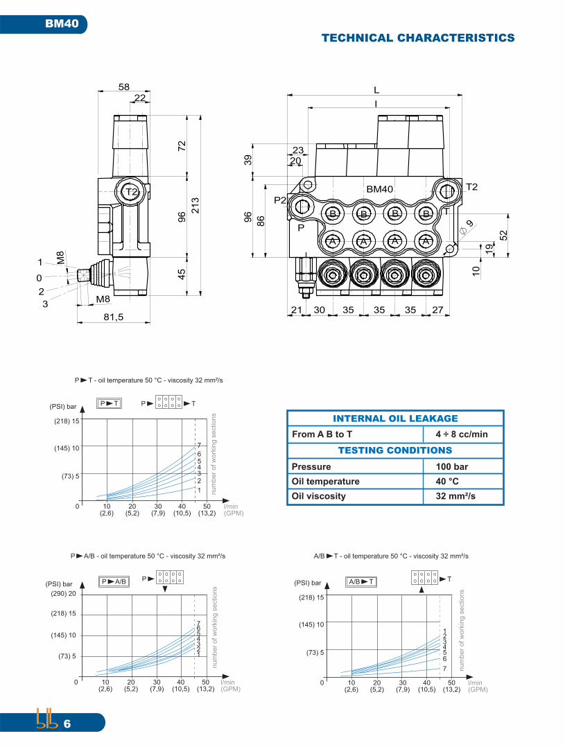
TECHNICAL CHARACTERISTICS
1
A
P
P2
0
B
2
3
96
86
39
58
22
96
72
213
45
81,5
M8
M8
3535
A
353021 27
9
52
B
19
10
23
L
I
BM40 T2
TB
AA
B
T2
20
P T - oil temperature 50 °C - viscosity 32 mm²/s
(PSI) bar
(218) 15
(145) 10
(73) 5
0 10(2,6)
20(5,2)
30(7,9)
40(10,5)
50(13,2)
P T P T
l/min(GPM)
65432
1
7
nu
mb
er
of
wo
rkin
g s
ectio
ns
(PSI) bar
(290) 20
(218) 15
(145) 10
0 10(2,6)
20(5,2)
30(7,9)
40(10,5)
50(13,2)
P A/B P
l/min(GPM)
(73) 5
P A/B - oil temperature 50 °C - viscosity 32 mm²/s
12345
76
nu
mb
er
of
wo
rkin
g s
ectio
ns
(PSI) bar
(218) 15
(145) 10
(73) 5
0 10(2,6)
20(5,2)
30(7,9)
40(10,5)
50(13,2)
T
l/min(GPM)
A/B T - oil temperature 50 °C - viscosity 32 mm²/s
A/B T
7
654321
nu
mb
er
of
wo
rkin
g s
ectio
ns
INTERNAL OIL LEAKAGE
4 ÷ 8 cc/min
TESTING CONDITIONS
From A B to T
100 barPressure
40 °COil temperature
32 mm²/sOil viscosity
7
BM40
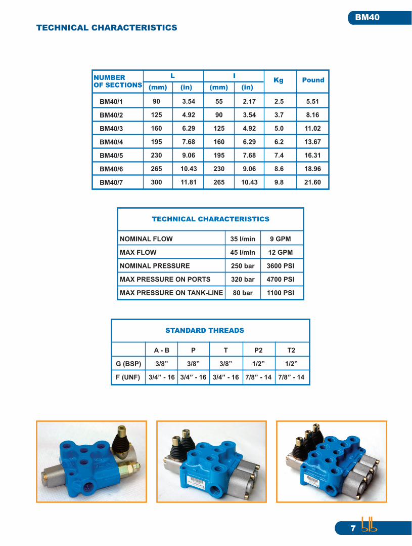
TECHNICAL CHARACTERISTICS
NOMINAL FLOW
MAX FLOW
NOMINAL PRESSURE
MAX PRESSURE ON PORTS
MAX PRESSURE ON TANK-LINE
TECHNICAL CHARACTERISTICS
35 l/min
45 l/min
250 bar
320 bar
80 bar
9 GPM
12 GPM
3600 PSI
4700 PSI
1100 PSI
G (BSP)
F (UNF)
STANDARD THREADS
A - B
3/8”
3/4” - 16
P
3/8”
3/4” - 16
T
3/8”
3/4” - 16
P2
1/2”
7/8” - 14
T2
1/2”
7/8” - 14
BM40/1
BM40/2
BM40/3
BM40/4
BM40/5
BM40/6
BM40/7
NUMBEROF SECTIONS
90
125
160
195
230
265
300
(mm) (in)
55
90
125
160
195
230
265
2.5
3.7
5.0
6.2
7.4
8.6
9.8
Kg
3.54
4.92
6.29
7.68
9.06
10.43
11.81
2.17
3.54
4.92
6.29
7.68
9.06
10.43
Pound
5.51
8.16
11.02
13.67
16.31
18.96
21.60
L I
(mm) (in)

8
BM40
RELIEF VALVES
BM __ / __ __ __ (_) __ / __ __ __ / __
RELIEF VALVE X COD. 803009
Low pressure adjustable relief valve. Allows the external adjustament of the relief valve pressure between 30 to 90 bar. The pressure
rating is based on a pre-set fl ow of 8 l/min.
PRESSURE RANGE 30 ÷ 90 bar STANDARD RELIEF SETTING 70 bar
RELIEF VALVE U COD. 803002
High pressure adjustable relief valve. Allows the external adjustament of the relief valve pressure between 80 to 230 bar. The pres-
sure rating is based on a pre-set fl ow of 8 l/min.
PRESSURE RANGE 80 ÷ 230 bar STANDARD RELIEF SETTING 140 bar
RELIEF VALVE K COD. 803010
Very high pressure adjustable relief valve. Allows the external adjustament of the relief valve pressure between 150 to 300 bar. The
pressure rating is based on a pre-set fl ow of 8 l/min.
PRESSURE RANGE 150 ÷ 300 bar STANDARD RELIEF SETTING 200 bar

9
BM40
RELIEF VALVES
COD. 560189 KIT VNR
Standard on all Blb monoblock valves. Each valve has only one load check. The load check prevents the fall of a cylinder as the spool
is shifted. It also prevents the backfl ow of oil from the work port to the inlet.
BM __ / __ __ __ (_) __ / __ __ __ / __
A
B
A
B
BM40/4 T2
B
P2
A
TB
A
COD. 020027 RELIEF VALVE LOCK KIT PB
Prevents users from altering the factory pre-set relief valve.
COD. 832010RELIEF VALVE PLUG RVP
Replaces the relief valve in closed center systems where the relief valve is not required.
10
BM40
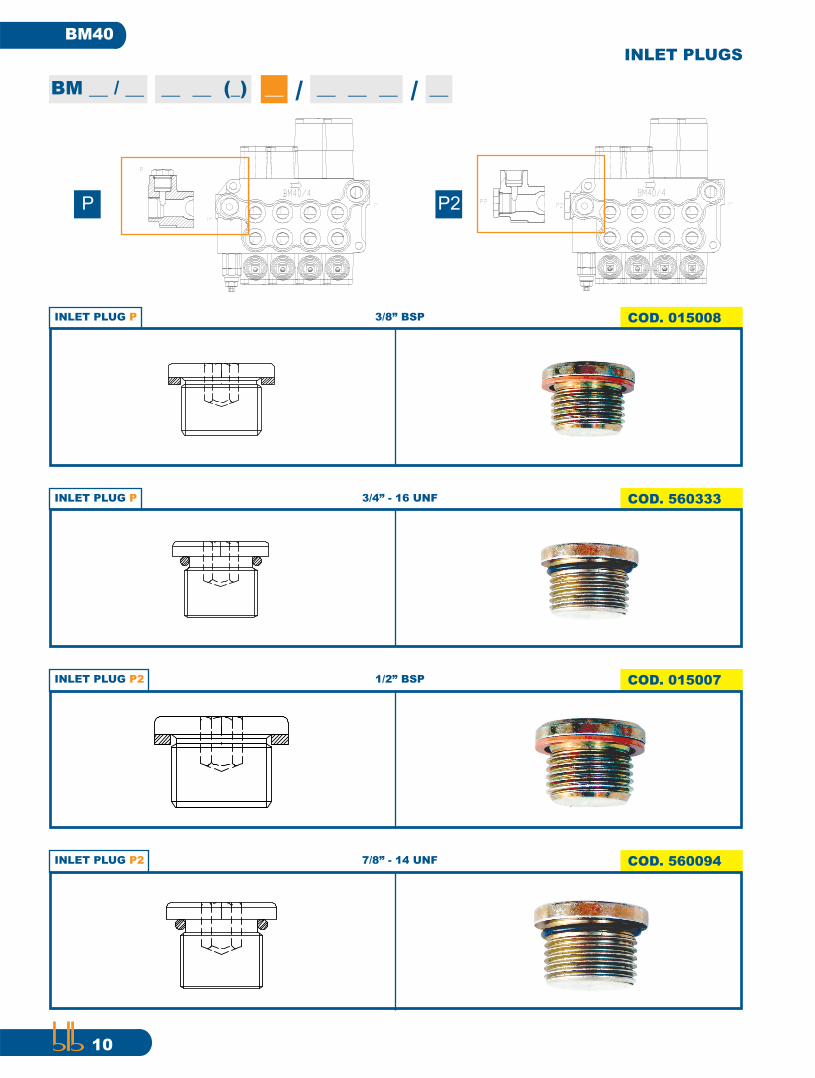
INLET PLUGS
BM __ / __ __ __ (_) __ / __ __ __ / __
INLET PLUG P2 COD. 015007 1/2” BSP
INLET PLUG P COD. 015008 3/8” BSP
INLET PLUG P COD. 560333 3/4” - 16 UNF
INLET PLUG P2 COD. 560094 7/8” - 14 UNF
B
P
T2
TBM40/4
B
A
B
A
B
A
P2
A
P
T2
P
A
P2P2
B
A A A
BM40/4
B B B
T
P P2

11
BM40
BM __ / __ __ __ (_) __ / __ __ __ / __
ACTUATORS
MANUAL MO COD. 801001
Manual lever control for manual operation. Features 2 angles 90° - 180°.
MANUAL WITHOUT LEVER MW COD. 801035
Manual control without lever handle.
A
C
The actuator
orientation
is “A” if not
differently required
SAFETY MANUAL LEVER MX COD. 801175
Manual control with safety lever system. Allows the operation of the lever only after the lock system is released.

12
BM40
BM __ / __ __ __ (_) __ / __ __ __ / __
ACTUATORS
CAM DO COD. 801044
Cam actuator.
COD. 801162MANUAL WITH LIMITING DEVICE ML
Manual lever control with limiter of the spool movement.
COD. 560644 HYDRAULIC HO
Hydraulic actuator for remote control.
MANUAL WITH CAM MC COD. 801065
Manual lever control with cam.

13
BM40
BM __ / __ __ __ (_) __ / __ __ __ / __
ACTUATORS
JOYSTICK JS COD. 801120
Operates two spools with one lever handle. Two spools can be operated indipendently or simultaneously, depending on the move-
ment of the handle. Joystick requires to be assembled with spools AS, BS, DS or KS.
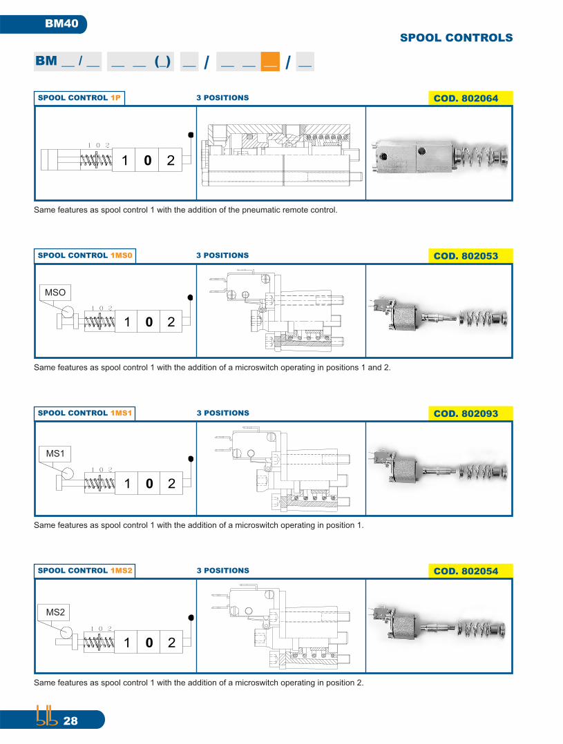
PNEUMATIC 1P COD. 802064
Pneumatic actuator for remote control mounted on the spool control side. It can be combined with other manual actuators.
1 0 2
01 2
MANUAL REMOTE CONTROL FO COD. 023040
Manual lever control for manual remote operation.
SAFETY MANUAL REMOTE CONTROL FA COD. 023047
Manual lever control with safety system for manual remote operation. Allows the operation of the lever only after the lock system is
released.

14
BM40
BM __ / __ __ __ (_) __ / __ __ __ / __
ACTUATORS
COD. 023043 CABLE TYPE CA2.0
COD. 023044 CABLE TYPE CA2.5
COD. 801023 CABLE ADAPTER FL
Cable adapter for cable control. No hand lever is provided.
Cable 2.0 mt. long.
Cable 2.5 mt. long.

15
BM40
SPOOLS
BM __ / __ __ __ (_) __ / __ __ __ / __
SPOOL A COD. 560096
4-WAY / 3-POSITION SPOOL. Provides control of double-acting cylinders or bi-directional hydraulic motors. In position 0 work ports
are blocked.
0
P T
B A
1 2
SPOOL AS COD. 560111
4-WAY / 3-POSITION SPOOL. Same features as spool A but with threaded spool end. Required to assembly the joystick (JS) or for special applications.
0
P T
B A
1 2
SPOOL SP COD. 560109
4-WAY / 3-POSITION SPOOL. Same features as spool AS but without meetering. Required for special applications (i.e. woodsplitter).
0
P T
B A
1 2
0123
3
AB
16
BM40
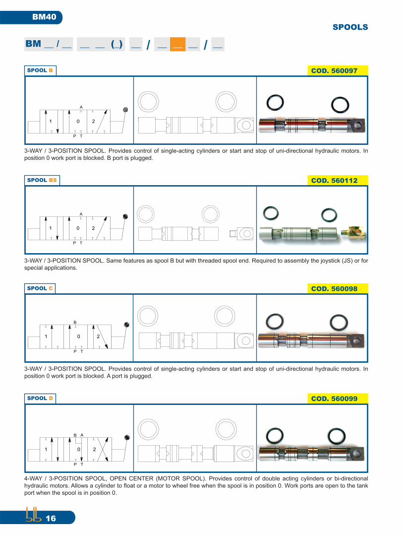
SPOOLS
BM __ / __ __ __ (_) __ / __ __ __ / __
SPOOL C COD. 560098
3-WAY / 3-POSITION SPOOL. Provides control of single-acting cylinders or start and stop of uni-directional hydraulic motors. In
position 0 work port is blocked. A port is plugged.
TP
0
B
1 2
SPOOL D COD. 560099
4-WAY / 3-POSITION SPOOL, OPEN CENTER (MOTOR SPOOL). Provides control of double acting cylinders or bi-directional
hydraulic motors. Allows a cylinder to fl oat or a motor to wheel free when the spool is in position 0. Work ports are open to the tank
port when the spool is in position 0.
P
0
T
B A
1 2
SPOOL BS COD. 560112
3-WAY / 3-POSITION SPOOL. Same features as spool B but with threaded spool end. Required to assembly the joystick (JS) or for
special applications.
0
P T
A
1 2
SPOOL B COD. 560097
3-WAY / 3-POSITION SPOOL. Provides control of single-acting cylinders or start and stop of uni-directional hydraulic motors. In
position 0 work port is blocked. B port is plugged.
0
P T
A
1 2
17
BM40
SPOOLS
BM __ / __ __ __ (_) __ / __ __ __ / __
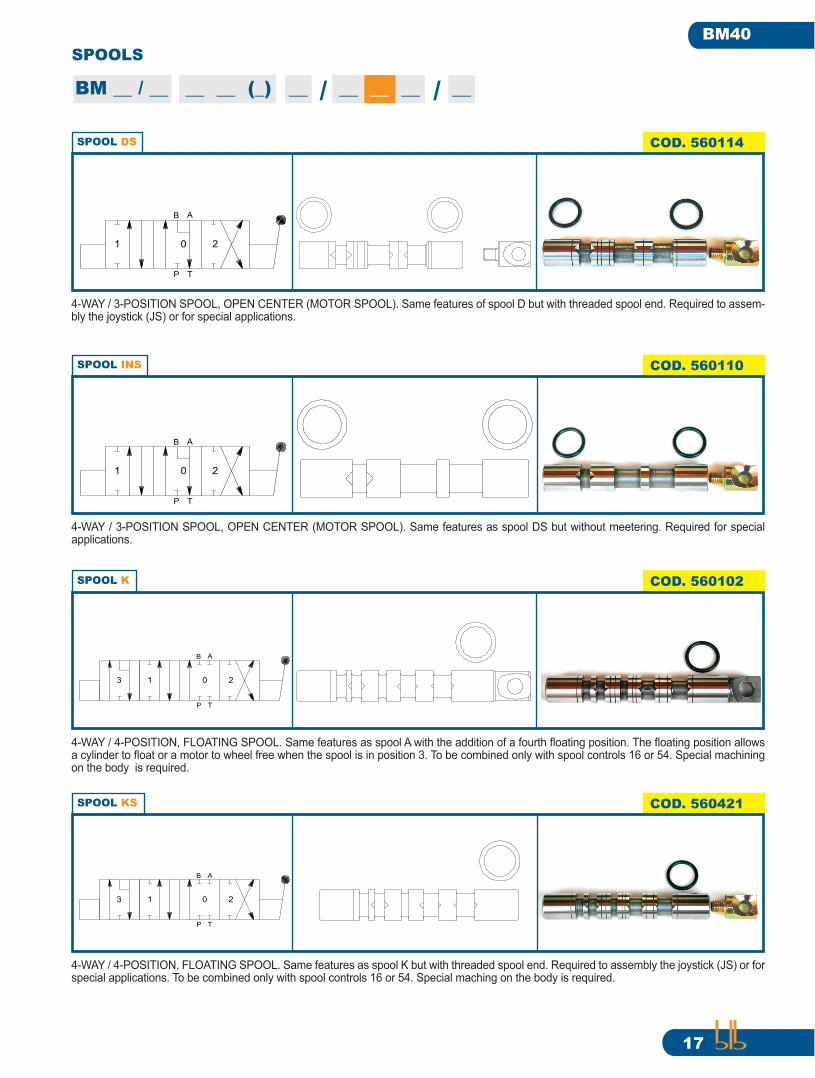
SPOOL K COD. 560102
4-WAY / 4-POSITION, FLOATING SPOOL. Same features as spool A with the addition of a fourth fl oating position. The fl oating position allows a cylinder to fl oat or a motor to wheel free when the spool is in position 3. To be combined only with spool controls 16 or 54. Special machining on the body is required.
2
P T
B A
1 03
SPOOL KS COD. 560421
4-WAY / 4-POSITION, FLOATING SPOOL. Same features as spool K but with threaded spool end. Required to assembly the joystick (JS) or for special applications. To be combined only with spool controls 16 or 54. Special maching on the body is required.
2
P T
B A
1 03
SPOOL DS COD. 560114
4-WAY / 3-POSITION SPOOL, OPEN CENTER (MOTOR SPOOL). Same features of spool D but with threaded spool end. Required to assem-bly the joystick (JS) or for special applications.
P
0
T
B A
1 2
SPOOL INS COD. 560110
4-WAY / 3-POSITION SPOOL, OPEN CENTER (MOTOR SPOOL). Same features as spool DS but without meetering. Required for special applications.
P
0
T
B A
1 2
18
BM40
SPOOLS
BM __ / __ __ __ (_) __ / __ __ __ / __
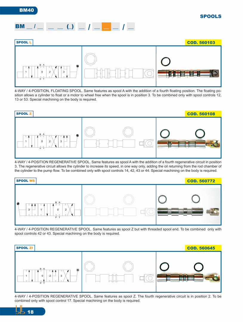
SPOOL L COD. 560103
4-WAY / 4-POSITION, FLOATING SPOOL. Same features as spool A with the addition of a fourth fl oating position. The fl oating po-
sition allows a cylinder to fl oat or a motor to wheel free when the spool is in position 3. To be combined only with spool controls 12,
13 or 53. Special machining on the body is required.
2
P T
B A
1 0 3
SPOOL Z COD. 560108
4-WAY / 4-POSITION REGENERATIVE SPOOL. Same features as spool A with the addition of a fourth regenerative circuit in position
3. The regenerative circuit allows the cylinder to increase its speed, in one way only, adding the oil returning from the rod chamber of
the cylinder to the pump fl ow. To be combined only with spool controls 14, 42, 43 or 44. Special machining on the body is required.
2
P T
B A
1 0 3
SPOOL ZI COD. 560645
4-WAY / 4-POSITION REGENERATIVE SPOOL. Same features as spool Z. The fourth regenerative circuit is in position 2. To be
combined only with spool control 17. Special machining on the body is required.
2
P T
B A
1 0 3
SPOOL WS COD. 560772
4-WAY / 4-POSITION REGENERATIVE SPOOL. Same features as spool Z but with threaded spool end. To be combined only with
spool controls 42 or 43. Special machining on the body is required.
2
P T
B A
1 03
19
BM40
COD. 560107
COD. 560228
BM __ / __ __ __ (_) __ / __ __ __ / __
SPOOLS
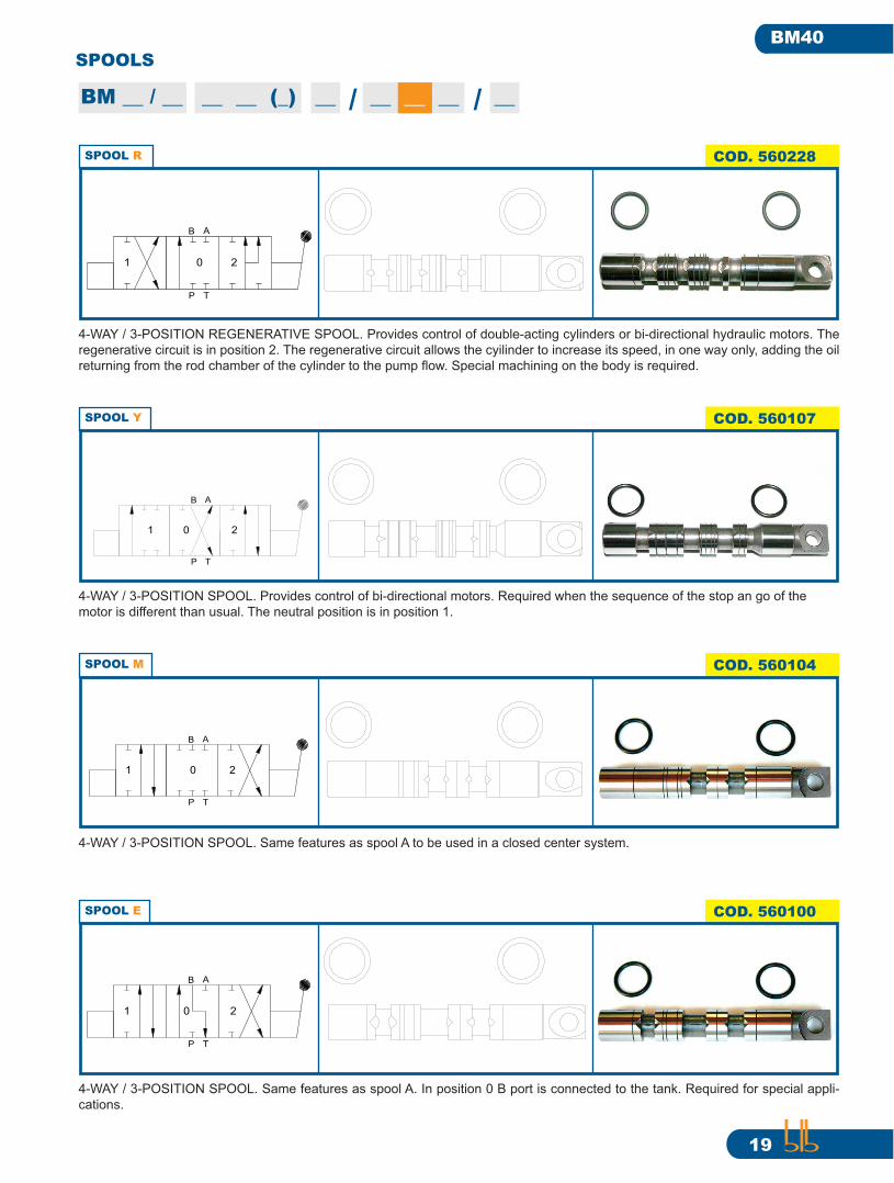
SPOOL E COD. 560100
4-WAY / 3-POSITION SPOOL. Same features as spool A. In position 0 B port is connected to the tank. Required for special appli-
cations.
1 0
P T
B A
2
SPOOL M COD. 560104
4-WAY / 3-POSITION SPOOL. Same features as spool A to be used in a closed center system.
01
P T
AB
2
SPOOL Y
4-WAY / 3-POSITION SPOOL. Provides control of bi-directional motors. Required when the sequence of the stop an go of the
motor is different than usual. The neutral position is in position 1.
1
T
AB
0
P
2
SPOOL R
4-WAY / 3-POSITION REGENERATIVE SPOOL. Provides control of double-acting cylinders or bi-directional hydraulic motors. The
regenerative circuit is in position 2. The regenerative circuit allows the cyilinder to increase its speed, in one way only, adding the oil
returning from the rod chamber of the cylinder to the pump fl ow. Special machining on the body is required.
B
0
T
1
P
A
2

20
BM40
SPOOLS
SPOOL F COD. 560101
4-WAY / 3-POSITION SPOOL. Same features as spool A. In position 0 A port is connected to the tank. Required for special appli-
cations.
AB
1
P
0
T
2
BM __ / __ __ __ (_) __ / __ __ __ / __

21
BM40
0123
3
SPOOL CONTROLS
BM __ / __ __ __ (_) __ / __ __ __ / __
SPOOL CONTROL 3 COD. 802003
The spool is detented in position 2 and returns to 0 from position 1 when the handle is released.
3 POSITIONS
1
1 0 2
0 2
SPOOL CONTROL 1 COD. 802001
The spool returns to position 0 when the handle is released.
3 POSITIONS
0
1 0 2
1 2
SPOOL CONTROL 2 COD. 802002
The spool is detented in position 1 and returns to 0 from position 2 when the handle is released.
3 POSITIONS
1
1 0 2
0 2

22
BM40
SPOOL CONTROLS
BM __ / __ __ __ (_) __ / __ __ __ / __
SPOOL CONTROL 4 COD. 802004
The spool returns to position 0 when the handle is released.
2 POSITIONS
0
0 2
2
SPOOL CONTROL 5 COD. 802005
The spool returns to position 0 when the handle is released.
2 POSITIONS
01
1 0
SPOOL CONTROL 6 COD. 802006
The spool returns to position 1 when the handle is released.
3 POSITIONS
1
01 2
SPOOL CONTROL 7 COD. 802007
The spool returns to position 2 when the handle is released.
3 POSITIONS
21 0
2

23
BM40
SPOOL CONTROLS
BM __ / __ __ __ (_) __ / __ __ __ / __
0 2
0 2
SPOOL CONTROL 10
SPOOL CONTROL 11 COD. 802011
The spool is detented in both positions. The neutral position is absent.
2 POSITIONS
20
1 2
COD. 802010
The spool is detented in both positions.
2 POSITIONS
SPOOL CONTROL 9 COD. 802009
The spool is detented in both positions.
2 POSITIONS
0
1 0
1
SPOOL CONTROL 8 COD. 802008
The spool is detented in all three positions.
3 POSITIONS
1 20
1 0 2

24
BM40
SPOOL CONTROLS
BM __ / __ __ __ (_) __ / __ __ __ / __
SPOOL CONTROL 14 COD. 802045
The spool returns to position 0 when the handle is released. To be combined only with spool Z.
4 POSITIONS
0
1 0 2
3
3
1 2
SPOOL CONTROL 13 COD. 802013
The spool is detented in all positions. To be combined only with spool L.
4 POSITIONS
1
1 0 2 3
30 2
SPOOL CONTROL 12 COD. 802012
The spool returns to 0 from positions 1 and 2 when the handle is released. Position 3 is detented. To be combined only with spool L.
4 POSITIONS
31 0 2
301 2
SPOOL CONTROL 16 COD. 802099
The spool returns to 0 from positions 1 and 2 when the handle is released. Position 3 is detented. To be combined only with spool K.
4 POSITIONS
1
1 0 2
203
3
25
BM40
SPOOL CONTROLS
BM __ / __ __ __ (_) __ / __ __ __ / __
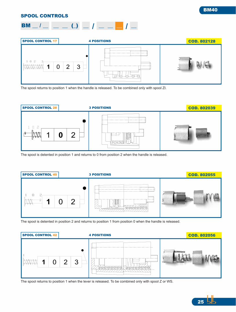
SPOOL CONTROL 40 COD. 802055
The spool is detented in position 2 and returns to position 1 from position 0 when the handle is released.
3 POSITIONS
2
1 0 2
1 0
SPOOL CONTROL 28 COD. 802039
The spool is detented in position 1 and returns to 0 from position 2 when the handle is released.
3 POSITIONS
1
1 0 2
0 2
SPOOL CONTROL 17 COD. 802128
The spool returns to position 1 when the handle is released. To be combined only with spool ZI.
4 POSITIONS
0
1 0 2
3
3
1 2
SPOOL CONTROL 42 COD. 802056
The spool returns to position 1 when the lever is released. To be combined only with spool Z or WS.
4 POSITIONS
1 0 3
1
2

26
BM40
SPOOL CONTROLS
BM __ / __ __ __ (_) __ / __ __ __ / __
SPOOL CONTROL 43 COD. 802129
The spool returns to position 1 when the lever is released. To be combined only with spool Z or WS.
4 POSITIONS
1 0 3
1
2
SPOOL CONTROL 44 COD. 802084
The spool is detented in pos 3 and returns to 1 from positions 2 and 0. To be combined only with spool Z.
4 POSITIONS
1
31 0 2
30 2
SPOOL CONTROL 53 COD. 802192
The spool returns to 0 from positions 1 and 2 when the handle is released. Position 3 is detented. To be combined only with spool L.
4 POSITIONS
31 0 2
301 2
SPOOL CONTROL 54 COD. 802193
The spool returns to 0 from positions 1 and 2 when the handle is released. Position 3 is detented. To be combined only with spool K.
4 POSITIONS
1
1 0 2
203
3

27
BM40
SPOOL CONTROLS
BM __ / __ __ __ (_) __ / __ __ __ / __
SPOOL CONTROL 58 COD. 802226
The spool is detented in position 1 and returns to 0 from position 2 when the handle is released.
3 POSITIONS
1
1 0 2
0 2
SPOOL CONTROL 59 COD. 802227
The spool is detented in position 2 and returns to 0 from position 1 when the handle is released.
3 POSITIONS
1
1 0 2
0 2
SPOOL CONTROL 1DC COD. 802076
Same features as spool control 1 with the addition of a threaded pin which allows to operate the spool also from the side opposite
to the manual control.
3 POSITIONS
0
1 0 2
1 2
SPOOL CONTROL 1F COD. 802070
Same features as spool control 1 with the addition of the connection kit to cable remote control. To be assembled with manual
remote control FO-FA and cable CA.
3 POSITIONS
1
1 0 2
0 2
28
BM40
SPOOL CONTROLS
BM __ / __ __ __ (_) __ / __ __ __ / __
SPOOL CONTROL 1MS0 COD. 802053
Same features as spool control 1 with the addition of a microswitch operating in positions 1 and 2.
3 POSITIONS
0
MS0
1 0 2
1 2
SPOOL CONTROL 1MS1 COD. 802093
Same features as spool control 1 with the addition of a microswitch operating in position 1.
3 POSITIONS
0
MS1
1 0 2
1 2
SPOOL CONTROL 1MS2 COD. 802054
Same features as spool control 1 with the addition of a microswitch operating in position 2.
3 POSITIONS
0
MS2
1 0 2
21
SPOOL CONTROL 1P COD. 802064
Same features as spool control 1 with the addition of the pneumatic remote control.
3 POSITIONS
1 0 2
01 2
MSO
MS1
MS2

29
BM40
BM __ / __ __ __ (_) __ / __ __ __ / __
SPOOL CONTROLS
SPOOL CONTROL 1MSW2 COD. 802178
Same features as spool control 1 with the addition of a waterproof microswitch operating in position 2.
3 POSITIONS
SPOOL CONTROL 1MSW1 COD. 802177
Same features as spool control 1 with the addition of a waterproof microswitch operating in position 1.
3 POSITIONS
0
MSW1
1 0 2
1 2
2
MSW2
1 0 2
01
SPOOL CONTROL 1MSW0 COD. 802176
Same features as spool control 1 with the addition of a waterproof microswitch operating in positions 1 and 2.
3 POSITIONS
0
MSW0
1 0 2
1 2
MSW1
MSW2
MSW0

30
BM40
OUTLET PLUGS
BM __ / __ __ __ (_) / __ __ __ __/__
CARRY OVER CO COD. 832006
Allows the installation of another valve downstream from the fi rst. Assembled on T2 port of a valve. UNF threaded.
7/8” - 14 UNF
CARRY OVER CO COD. 832004
Allows the installation of another valve downstream from the fi rst. Assembled on T2 port of a valve. BSP threaded.
1/2” BSP
CLOSED CENTER PLUG CCP COD. 8320087/8” - 14 UNF
Turns an open center circuit into a closed center one. UNF threaded.
CLOSED CENTER PLUG CCP COD. 832007
Turns an open center circuit into a closed center one. BSP threaded.
1/2” BSP
B
CCP
CCP
TBM40/4
B
A
B
A
B
A
P
P2
A
T
T CCP
CCP
A
CO
TBM40/4
B
A
B
A
B
A
P
P2
B
CO
T
T
COCO

31
BM40
BM __ / __ __ __ (_) / __ __ __ __/__
OUTLET PLUG T2 COD. 560094
OUTLET PLUG T COD. 015008 3/8” BSP
7/8” - 14 UNF
OUTLET PLUG T COD. 560333 3/4” - 16 UNF
OUTLET PLUG T2 COD. 0150071/2” BSP
B
T
T2
BM40/4
B
A
B
A
B
A
P
P2
A A
T2
TBM40/4
B
A
B
A
B
A
P
P2
B
T2
OUTLET PLUGS

32
BM40
BLB srl
via Natta 1 - 36040 Brendola (VI) ITALY
phone +39 0444 401141 fax +39 0444 401086
www.blbhydraulic.com e-mail: [email protected]