catalog-spiral wound gaskets
DESCRIPTION
procedureTRANSCRIPT
7/18/2019 Catalog-Spiral Wound Gaskets
http://slidepdf.com/reader/full/catalog-spiral-wound-gaskets 1/10
18 sealing materials
contents
Hofland® spiralwoundgaskets fig. G2004
properties
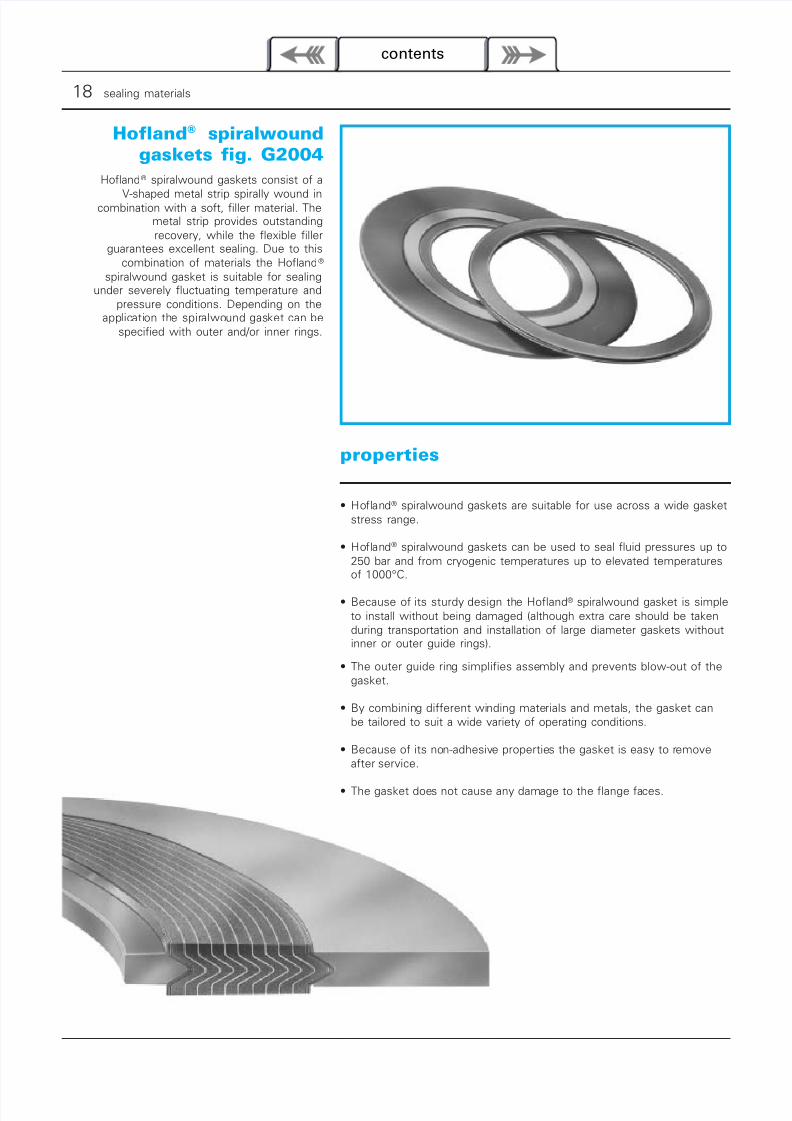
Hofland® spiralwound gaskets consist of a
V-shaped metal strip spirally wound incombination with a soft, filler material. The
metal strip provides outstandingrecovery, while the flexible filler
guarantees excellent sealing. Due to thiscombination of materials the Hofland®
spiralwound gasket is suitable for sealingunder severely fluctuating temperature and
pressure conditions. Depending on theapplication the spiralwound gasket can be
specified with outer and/or inner rings.
• Hofland® spiralwound gaskets are suitable for use across a wide gasketstress range.
• Hofland® spiralwound gaskets can be used to seal fluid pressures up to250 bar and from cryogenic temperatures up to elevated temperaturesof 1000°C.
• Because of its sturdy design the Hofland® spiralwound gasket is simpleto install without being damaged (although extra care should be takenduring transportation and installation of large diameter gaskets withoutinner or outer guide rings).
• The outer guide ring simplifies assembly and prevents blow-out of thegasket.
• By combining different winding materials and metals, the gasket canbe tailored to suit a wide variety of operating conditions.
• Because of its non-adhesive properties the gasket is easy to removeafter service.
• The gasket does not cause any damage to the flange faces.
7/18/2019 Catalog-Spiral Wound Gaskets
http://slidepdf.com/reader/full/catalog-spiral-wound-gaskets 2/10
section 1 | metallic and semi-metallic gaskets • spiralwound 19
contents
gasket stress range:
technical data
both sides confined
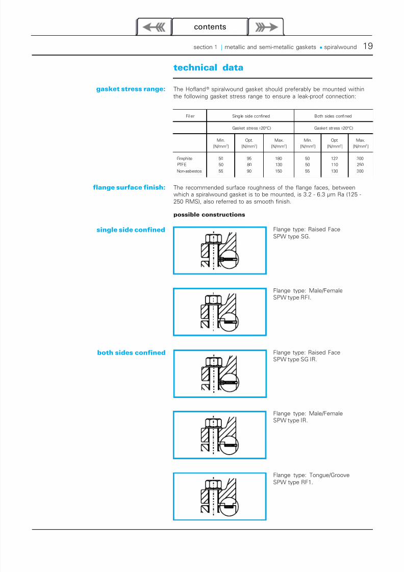
Flange type: Tongue/GrooveSPW type RF1.
Flange type: Male/FemaleSPW type IR.
Flange type: Raised FaceSPW type SG IR.
Flange type: Male/Female
SPW type RFI.
Flange type: Raised FaceSPW type SG.
flange surface finish:
possible constructions
single side confined
The Hofland® spiralwound gasket should preferably be mounted withinthe following gasket stress range to ensure a leak-proof connection:
Filler Single side confined Both sides confined
Gasket stress (20°C) Gasket stress (20°C)
Min.
[N/mm2]
Opt.
[N/mm2]
Max.
[N/mm2]
Min.
[N/mm2]
Opt.
[N/mm2]
Max.
[N/mm2 ]
Graphite 50 95 180 50 122 300
PTFE 50 80 130 50 110 250
Non-asbestos 55 90 150 55 130 300
The recommended surface roughness of the flange faces, betweenwhich a spiralwound gasket is to be mounted, is 3.2 - 6.3 µm Ra (125 -
250 RMS), also referred to as smooth finish.
7/18/2019 Catalog-Spiral Wound Gaskets
http://slidepdf.com/reader/full/catalog-spiral-wound-gaskets 3/10
20 sealing materials
contents
standard profiles
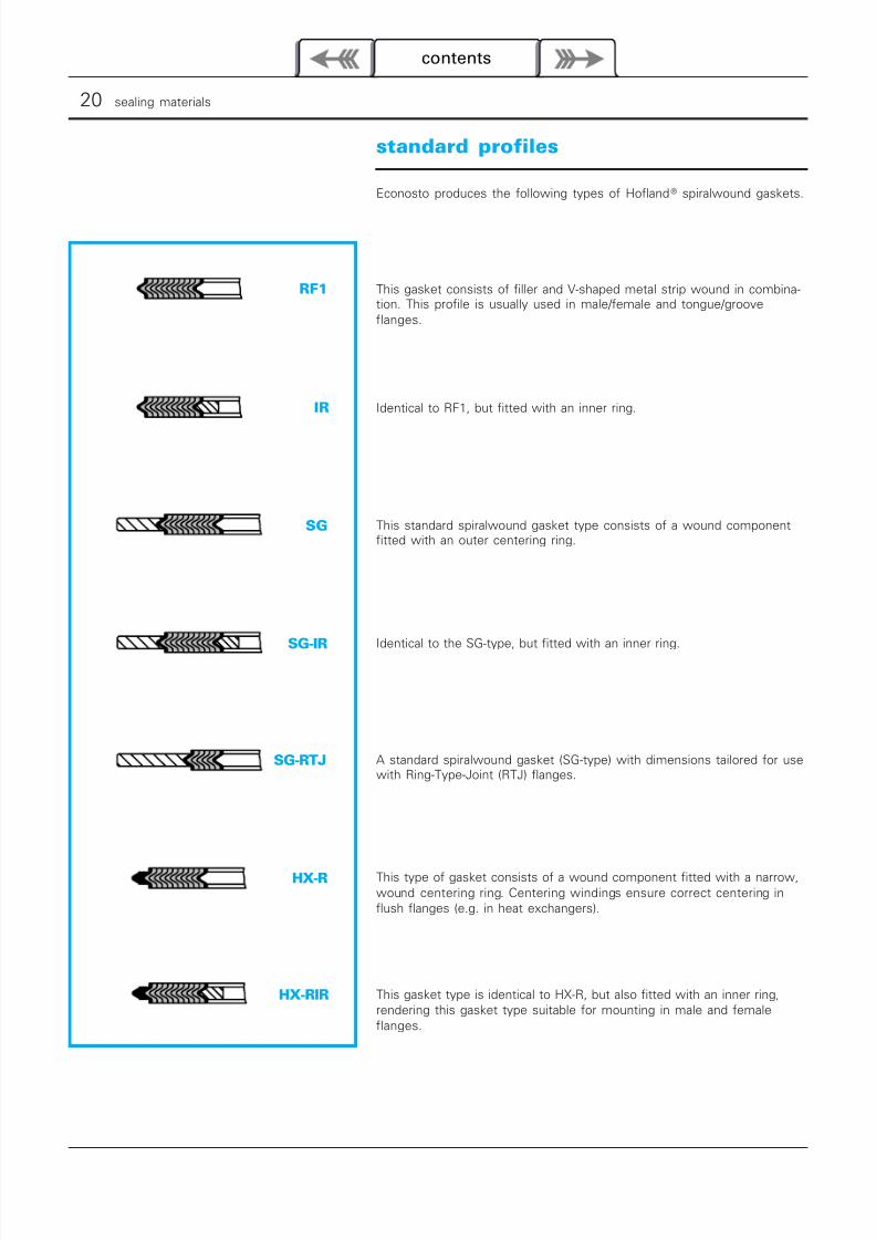
RF1
SG
IR
SG-IR
SG-RTJ
HX-R
HX-RIR
Econosto produces the following types of Hofland® spiralwound gaskets.
This gasket consists of filler and V-shaped metal strip wound in combina-tion. This profile is usually used in male/female and tongue/grooveflanges.
Identical to RF1, but fitted with an inner ring.
This standard spiralwound gasket type consists of a wound componentfitted with an outer centering ring.
Identical to the SG-type, but fitted with an inner ring.
A standard spiralwound gasket (SG-type) with dimensions tailored for usewith Ring-Type-Joint (RTJ) flanges.
This type of gasket consists of a wound component fitted with a narrow,wound centering ring. Centering windings ensure correct centering inflush flanges (e.g. in heat exchangers).
This gasket type is identical to HX-R, but also fitted with an inner ring,rendering this gasket type suitable for mounting in male and femaleflanges.
7/18/2019 Catalog-Spiral Wound Gaskets
http://slidepdf.com/reader/full/catalog-spiral-wound-gaskets 4/10
section 1 | metallic and semi-metallic gaskets • spiralwound 21
contents
profile with a GT-zone:
special profiles
special shapes
type MH
type TC/HH
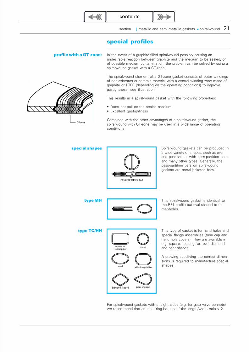
In the event of a graphite-filled spiralwound possibly causing anundesirable reaction between graphite and the medium to be sealed, orof possible medium contamination, the problem can be solved by using aspiralwound gasket with a GT-zone.
The spiralwound element of a GT-zone gasket consists of outer windingsof non-asbestos or ceramic material with a central winding zone made ofgraphite or PTFE (depending on the operating conditions) to improvegastightness, see illustration.
This results in a spiralwound gasket with the following properties:
• Does not pollute the sealed medium• Excellent gastightness
Combined with the other advantages of a spiralwound gasket, the
spiralwound with GT-zone may be used in a wide range of operatingconditions.
For spiralwound gaskets with straight sides (e.g. for gate valve bonnets)
we recommend that an inner ring be used if the length/width ratio > 2.
Spiralwound gaskets can be produced ina wide variety of shapes, such as ovaland pear-shape, with pass-partition barsand many other types. Generally, thepass-partition bars on spiralwoundgaskets are metal-jacketed bars.
This spiralwound gasket is identical tothe RF1 profile but oval shaped to fitmanholes.
This type of gasket is for hand holes andspecial flange assemblies (tube cap andhand hole covers). They are available ine.g. square, rectangular, oval diamond
and pear shapes.
A drawing specifying the correct dimen-sions is required to manufacture specialshapes.
7/18/2019 Catalog-Spiral Wound Gaskets
http://slidepdf.com/reader/full/catalog-spiral-wound-gaskets 5/10
22 sealing materials
contents
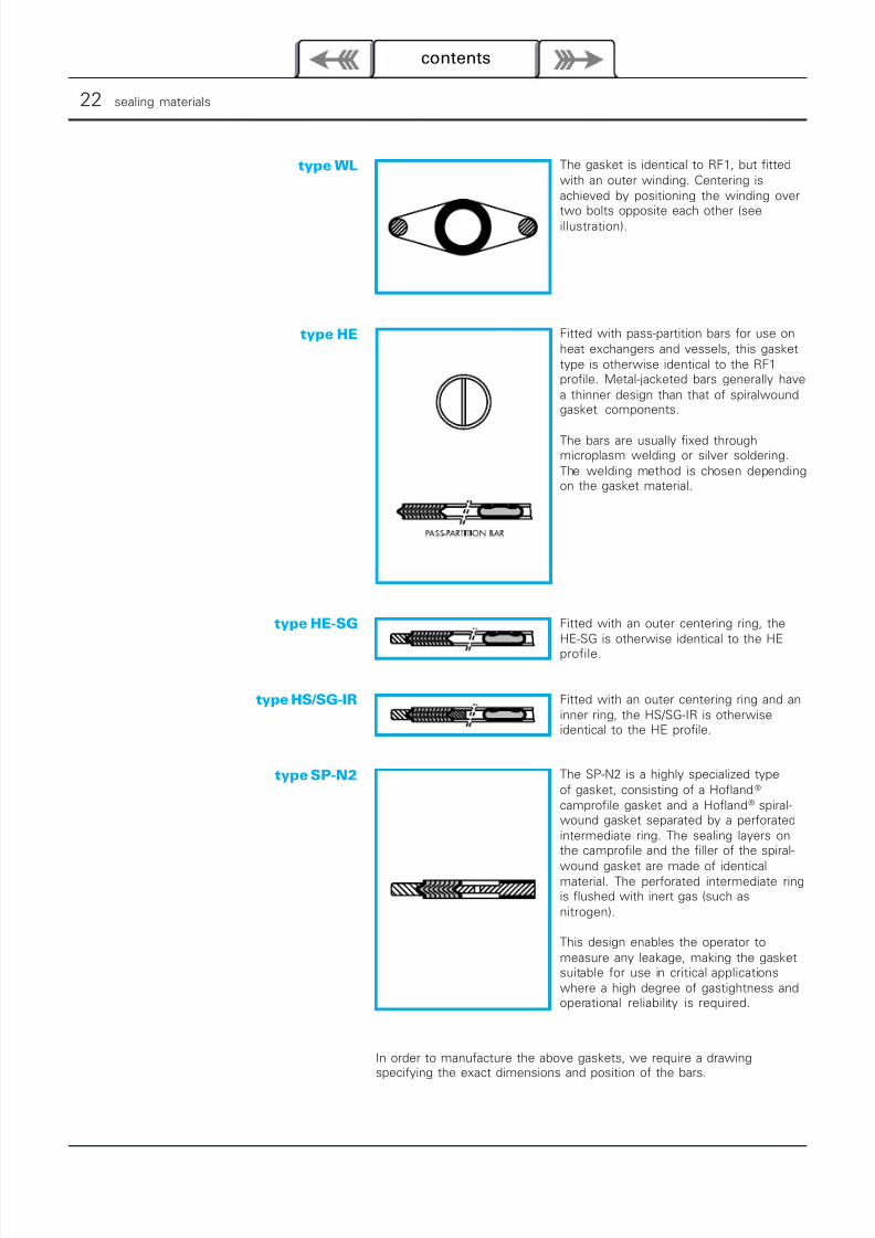
The gasket is identical to RF1, but fittedwith an outer winding. Centering isachieved by positioning the winding over
two bolts opposite each other (seeillustration).
type WL
type HE
type HE-SG
type HS/SG-IR
type SP-N2
In order to manufacture the above gaskets, we require a drawingspecifying the exact dimensions and position of the bars.
Fitted with pass-partition bars for use onheat exchangers and vessels, this gaskettype is otherwise identical to the RF1profile. Metal-jacketed bars generally havea thinner design than that of spiralwoundgasket components.
The bars are usually fixed throughmicroplasm welding or silver soldering.The welding method is chosen dependingon the gasket material.
Fitted with an outer centering ring, theHE-SG is otherwise identical to the HE
profile.
Fitted with an outer centering ring and aninner ring, the HS/SG-IR is otherwiseidentical to the HE profile.
The SP-N2 is a highly specialized typeof gasket, consisting of a Hofland®
camprofile gasket and a Hofland® spiral-wound gasket separated by a perforatedintermediate ring. The sealing layers onthe camprofile and the filler of the spiral-
wound gasket are made of identicalmaterial. The perforated intermediate ringis flushed with inert gas (such asnitrogen).
This design enables the operator tomeasure any leakage, making the gasketsuitable for use in critical applicationswhere a high degree of gastightness andoperational reliability is required.
7/18/2019 Catalog-Spiral Wound Gaskets
http://slidepdf.com/reader/full/catalog-spiral-wound-gaskets 6/10
section 1 | metallic and semi-metallic gaskets • spiralwound 23
contents
profile selection
advantages of the centering ring:
advantages of the inner ring:
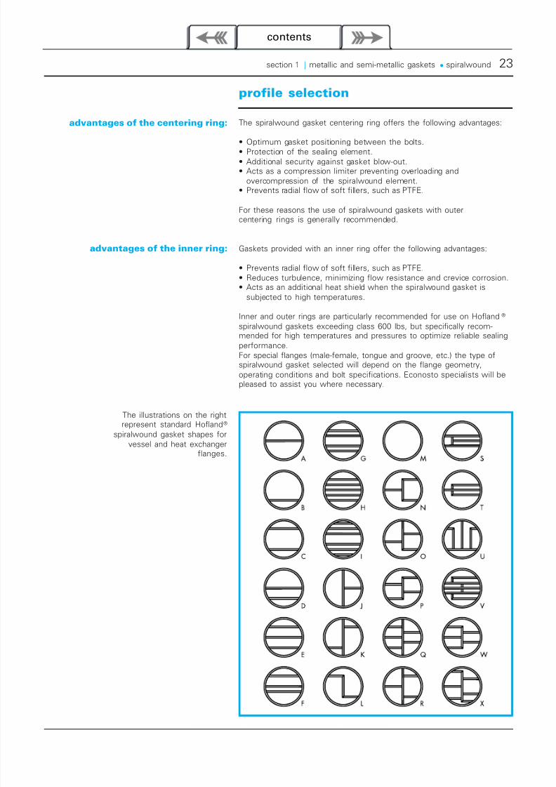
The illustrations on the rightrepresent standard Hofland®
spiralwound gasket shapes forvessel and heat exchanger
flanges.
The spiralwound gasket centering ring offers the following advantages:
• Optimum gasket positioning between the bolts.• Protection of the sealing element.• Additional security against gasket blow-out.• Acts as a compression limiter preventing overloading and
overcompression of the spiralwound element.• Prevents radial flow of soft fillers, such as PTFE.
For these reasons the use of spiralwound gaskets with outercentering rings is generally recommended.
Gaskets provided with an inner ring offer the following advantages:
• Prevents radial flow of soft fillers, such as PTFE.
• Reduces turbulence, minimizing flow resistance and crevice corrosion.• Acts as an additional heat shield when the spiralwound gasket is
subjected to high temperatures.
Inner and outer rings are particularly recommended for use on Hofland®
spiralwound gaskets exceeding class 600 lbs, but specifically recom-mended for high temperatures and pressures to optimize reliable sealingperformance.For special flanges (male-female, tongue and groove, etc.) the type ofspiralwound gasket selected will depend on the flange geometry,operating conditions and bolt specifications. Econosto specialists will bepleased to assist you where necessary.
7/18/2019 Catalog-Spiral Wound Gaskets
http://slidepdf.com/reader/full/catalog-spiral-wound-gaskets 7/10
24 sealing materials
contents
ring and winding material selection
The material selected for the inner ringand winding metal is usually SS316L for
both carbon steel and stainless steelflanges. In other cases, it is normally thesame material as selected for the piping
system, in order to prevent corrosionproblems. In highly corrosive
applications PTFE may beused for the inner rings.
The outer centering ring is generallymade of carbon steel with an anti-
corrosion coating; however, the ringmay also be manufactured in the same
metal as the pipe system to prevente.g. galvanic corrosion.
Hofland® spiralwound gasketsare available ex stock in
most standard materials.
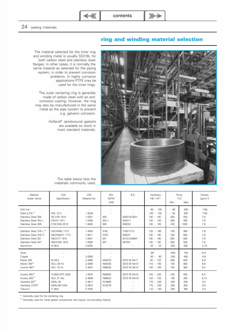
The table below lists thematerials commonly used.
Material
(trade name)
DIN
Specification
DIN
Material No.
AISI
ASTM
UNS
B.S. Hardness
HB / HV*
Temp.
[°C]
Min. Max.
Density
[gr/cm3]
Soft Iron - - - - 90 - 100 - 60 500 7.85
Steel (LCS) (1) RSt. 37.2 1.0038 - - 100 - 130 - 40 500 7.85
Stainless Steel 304 X5 CrNi 1810 1.4301 304 304S15/16/31 130 - 180 -250 550 7.9
Stainless Steel 304 L X2CrNi 1911 1.4306 304 L 304S11 130 - 190 -250 550 7.9
Stainless Steel 309 X15CrNiSi 2012 1.4828 309 309S24 130 - 190 -100 1000 7.9
Stainless Steel 316 L (2) X2CrNiMo 1713 1.4404 316L 316S11/13 130 - 190 -100 550 7.9
Stainless Steel 316 Ti X6CrNiMoTi 1712 1.4571 316Ti 320S31 130 - 190 -100 550 7.8
Stainless Steel 321 X6CrNiTi 1810 1.4541 321 321S12/49/87 130 - 190 -250 550 7.9
Stainless Steel 347 X6CrNiNb 1810 1.4550 347 347S31 130 - 190 -250 550 7.9
Aluminium Al 99,5 3.0255 - - 20 - 23 -250 300 2.73
Silver - - - - 28* -250 750 10.5
Copper - 2.0090 - - 50 - 80 -250 400 8.9
Nickel 200 Ni 99,2 2.4066 N02200 3072-76 NA11 90 - 120 -250 600 8.9
Monel 400 ® NiCu 30 Fe 2.4360 N04400 3072-76 NA13 110 - 150 -125 600 8.8
Inconel 600 ® NiCr 15 Fe 2.4816 N06600 3072-76 NA14 120 - 180 -100 950 8.4
Incoloy 800 ® X10NiCrAITi 3220 1.4876 N08800 3072-76 NA15 140 - 220 -100 850 8.0
Incoloy 825®
NiCr 21 Mo 2.4858 N08825 3072-76 NA16 120 - 180 -100 450 8.14
Hastelloy B2®
NiMo 28 2.4617 N10665 - 170 - 230 -200 450 9.2
Hastelloy C276® NiMo16Cr15W 2.4819 N10276 - 170 - 230 -200 450 8.9
Titanium Ti 99,8 3.7025 - - 110 - 140 -250 350 4.5
(1) Generally used for the centering ring(2)
Generally used for metal gasket components that require non-corroding material
7/18/2019 Catalog-Spiral Wound Gaskets
http://slidepdf.com/reader/full/catalog-spiral-wound-gaskets 8/10
section 1 | metallic and semi-metallic gaskets • spiralwound 25
contents
filler selection
filler material:
PTFE:
non-asbestos:
Ceramica®:
graphite:
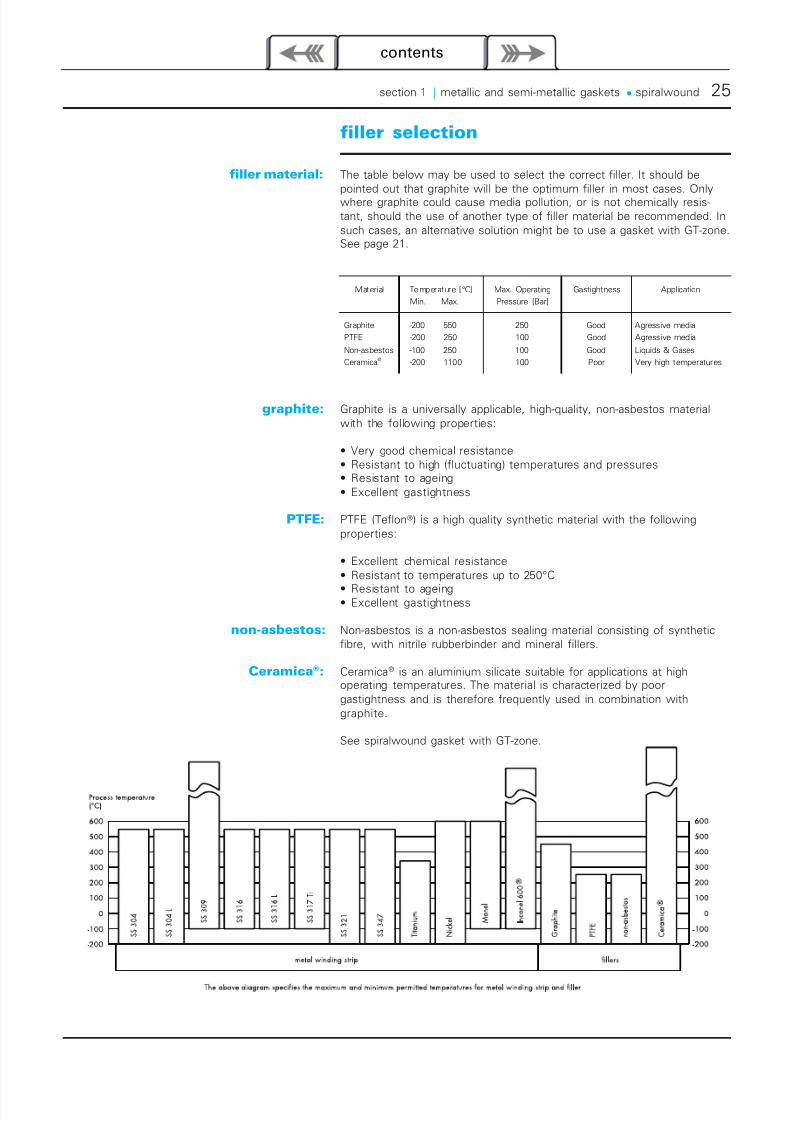
The table below may be used to select the correct filler. It should bepointed out that graphite will be the optimum filler in most cases. Onlywhere graphite could cause media pollution, or is not chemically resis-tant, should the use of another type of filler material be recommended. Insuch cases, an alternative solution might be to use a gasket with GT-zone.See page 21.
Graphite is a universally applicable, high-quality, non-asbestos materialwith the following properties:
• Very good chemical resistance• Resistant to high (fluctuating) temperatures and pressures• Resistant to ageing• Excellent gastightness
PTFE (Teflon®) is a high quality synthetic material with the followingproperties:
• Excellent chemical resistance• Resistant to temperatures up to 250°C
• Resistant to ageing• Excellent gastightness
Non-asbestos is a non-asbestos sealing material consisting of syntheticfibre, with nitrile rubberbinder and mineral fillers.
Ceramica® is an aluminium silicate suitable for applications at highoperating temperatures. The material is characterized by poorgastightness and is therefore frequently used in combination withgraphite.
See spiralwound gasket with GT-zone.
Material Temperature [°C]
Min. Max.
Max. Operating
Pressure [Bar]
Gastightness Application
Graphite -200 550 250 Good Agressive media
PTFE -200 250 100 Good Agressive media
Non-asbestos -100 250 100 Good Liquids & Gases
Ceramica®
-200 1100 100 Poor Very high temperatures
7/18/2019 Catalog-Spiral Wound Gaskets
http://slidepdf.com/reader/full/catalog-spiral-wound-gaskets 9/10
26 sealing materials
contents
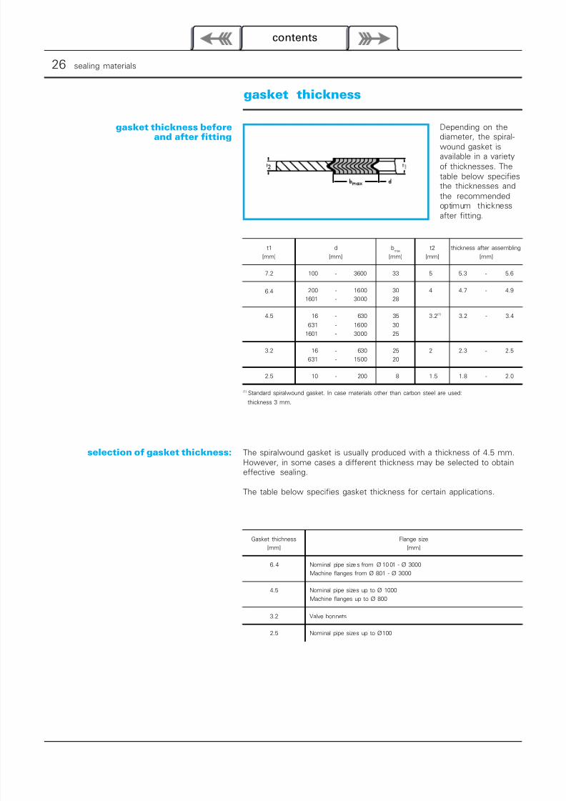
gasket thickness
gasket thickness before
and after fitting
selection of gasket thickness:
Depending on the
diameter, the spiral-wound gasket isavailable in a varietyof thicknesses. Thetable below specifiesthe thicknesses andthe recommendedoptimum thicknessafter fitting.
The spiralwound gasket is usually produced with a thickness of 4.5 mm.However, in some cases a different thickness may be selected to obtaineffective sealing.
The table below specifies gasket thickness for certain applications.
t1
[mm]
d
[mm]
bmax
[mm]
t2
[mm]
thickness after assembling
[mm]
7.2 100 - 3600 33 5 5.3 - 5.6
6.4 200 - 1600 30 4 4.7 - 4.9
1601 - 3000 28
4.5 16 - 630 35 3.2(1) 3.2 - 3.4
631 - 1600 30
1601 - 3000 25
3.2 16 - 630 25 2 2.3 - 2.5
631 - 1500 20
2.5 10 - 200 8 1.5 1.8 - 2.0
(1) Standard spiralwound gasket. In case materials other than carbon steel are used:
thickness 3 mm.
Gasket thichness
[mm]
Flange size
[mm]
6. 4 Nominal pipe size s from Ø 10 01 - Ø 3000
Machine flanges from Ø 801 - Ø 3000
4.5 Nominal pipe sizes up to Ø 1000
Machine flanges up to Ø 800
3.2 Valve bonnets
2.5 Nominal pipe sizes up to Ø 100
7/18/2019 Catalog-Spiral Wound Gaskets
http://slidepdf.com/reader/full/catalog-spiral-wound-gaskets 10/10
section 1 | metallic and semi-metallic gaskets • spiralwound 27
contents
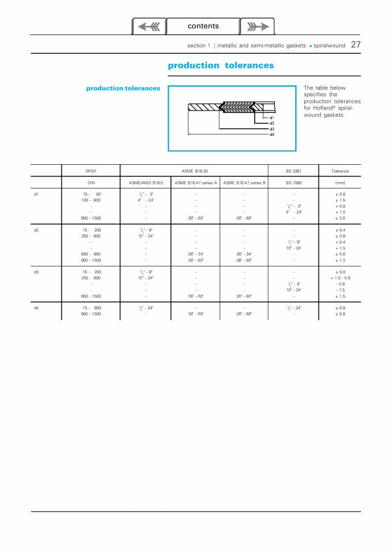
production tolerances
production tolerances The table below
specifies theproduction tolerancesfor Hofland® spiral-wound gaskets.
ASME B16.20SPW1 BS 3381 Tolerance
DIN ASME/ANSI B16.5 ASME B16.47 series A ASME B16.47 series B BS 1560 [mm]
d1 15 - 80 1 / 2" - 3" - - - ± 0.8100 - 600 4" - 24" - - - ± 1.5
- - - - 1 / 2" - 3" + 0.8
- - - - 4" - 24" + 1.5
650 - 1500 - 26" - 60" 26" - 60" - ± 3.0
d2 15 - 2001 /
2" - 8" - - - ± 0.4
250 - 600 10" - 24" - - - ± 0.8
- - - - 1 / 2" - 8" + 0.4
- - - - 10" - 24" + 1.5
650 - 850 - 26" - 34" 26" - 34" - ± 0.8
900 - 1500 - 36" - 60" 36" - 60" - ± 1.3
d3 15 - 2001 /
2" - 8" - - - ± 0.8
250 - 600 10" - 24" - - - + 1.5 - 0.8
- - - - 1 / 2" - 8" - 0.8
- - - - 10" - 24" - 1.5650 - 1500 - 26" - 60" 26" - 60" - ± 1.5
d4 15 - 600 1 / 2" - 24" - - 1 /
2" - 24" ± 0.8
650 - 1500 - 26" - 60" 26" - 60" - ± 0.8