catalog inductors - farnell element14safety precautions 44 power inductors / wire wound type...
TRANSCRIPT
CATALOG
Inductors
2015
2015.5 industrial.panasonic.com/
– 1 –
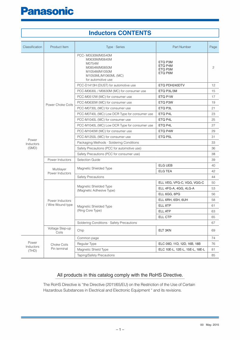
Inductors CONTENTS
All products in this catalog comply with the RoHS Directive.
The RoHS Directive is “the Directive (2011/65/EU) on the Restriction of the Use of Certain
Hazardous Substances in Electrical and Electronic Equipment “ and its revisions.
Classifi cation Product ltem Type ∙ Series Part Number Page
Power
Inductors
(SMD)
Power Choke Coils
PCC- M0530M/M0540M
M0630M/M0645M
M0754M
M0854M/M0850M
M1054M/M1050M
M1050ML/M1060ML (MC)
for automotive use
ETQ P3METQ P4METQ P5METQ P6M
2
PCC-D1413H (DUST) for automotive use ETQ PDH240DTV 12
PCC-M0630L / M0630M (MC) for consumer use ETQ P3L/3M 15
PCC-M0512W (MC) for consumer use ETQ P1W 17
PCC-M0630W (MC) for consumer use ETQ P3W 19
PCC-M0730L (MC) for consumer use ETQ P3L 21
PCC-M0740L (MC) Low DCR Type for consumer use ETQ P4L 23
PCC-M1040L (MC) for consumer use ETQ P4L 25
PCC-M1040L (MC) Low DCR Type for consumer use ETQ P4L 27
PCC-M1040W (MC) for consumer use ETQ P4W 29
PCC-M1250L (MC) for consumer use ETQ P5L 31
Packaging Methods ∙ Soldering Conditions 33
Safety Precautions (PCC for automotive use) 36
Safety Precautions (PCC for consumer use) 38
Power Inductors Selection Guide 39
Multilayer
Power Inductors
Magnetic Shielded TypeELG UEB 40
ELG TEA 42
Safety Precautions 44
Power Inductors
/ Wire Wound type
Magnetic Shielded Type
(Magnetic Adhesive Type)
ELL VEG, VFG-C, VGG, VGG-C 50
ELL 4FG-A, 4GG, 4LG-A 53
ELL 6GG, 6PG 56
Magnetic Shielded Type
(Ring Core Type)
ELL 6RH, 6SH, 6UH 58
ELL 8TP 61
ELL ATP 63
ELL CTP 65
Soldering Conditions ∙ Safety Precautions 67
Voltage Step-up
CoilsChip ELT 3KN 69
Power
Inductors
(THD)
Choke Coils
Pin terminal
Common page 74
Regular Type ELC 09D, 11D, 12D, 16B, 18B 76
Magnetic Shield Type ELC 10E-L, 12E-L, 15E-L, 18E-L 81
Taping/Safety Precautions 85
May. 201500
Design and specifications are each subject to change without notice. Ask factory for the current technical specifications before purchase and/or use.
Should a safety concern arise regarding this product, please be sure to contact us immediately.
Power Inductors
– 2 –
E
1 2
Q
3
P M Y F
4 5 6 7 8 9
Product Code InductanceClassification
10 11 12
SizeSuffixCoreWindingHeight
T
□ 5 mm size□ 6 mm size□ 7 mm size□ 8 mm size□10 mm size
P
N
M
K
C
4R7→220→101→
4.7 µH22 µH
100 µH
0.0
10.0
20.0
30.0
Ind
uc
tan
ce
(µ
H)
IDC (A)
40.0
50.0
60.0
0.0 0.5 1.0 1.5 2.0 2.5 3.0
25 °C
100 °C
125 °C
150 °C
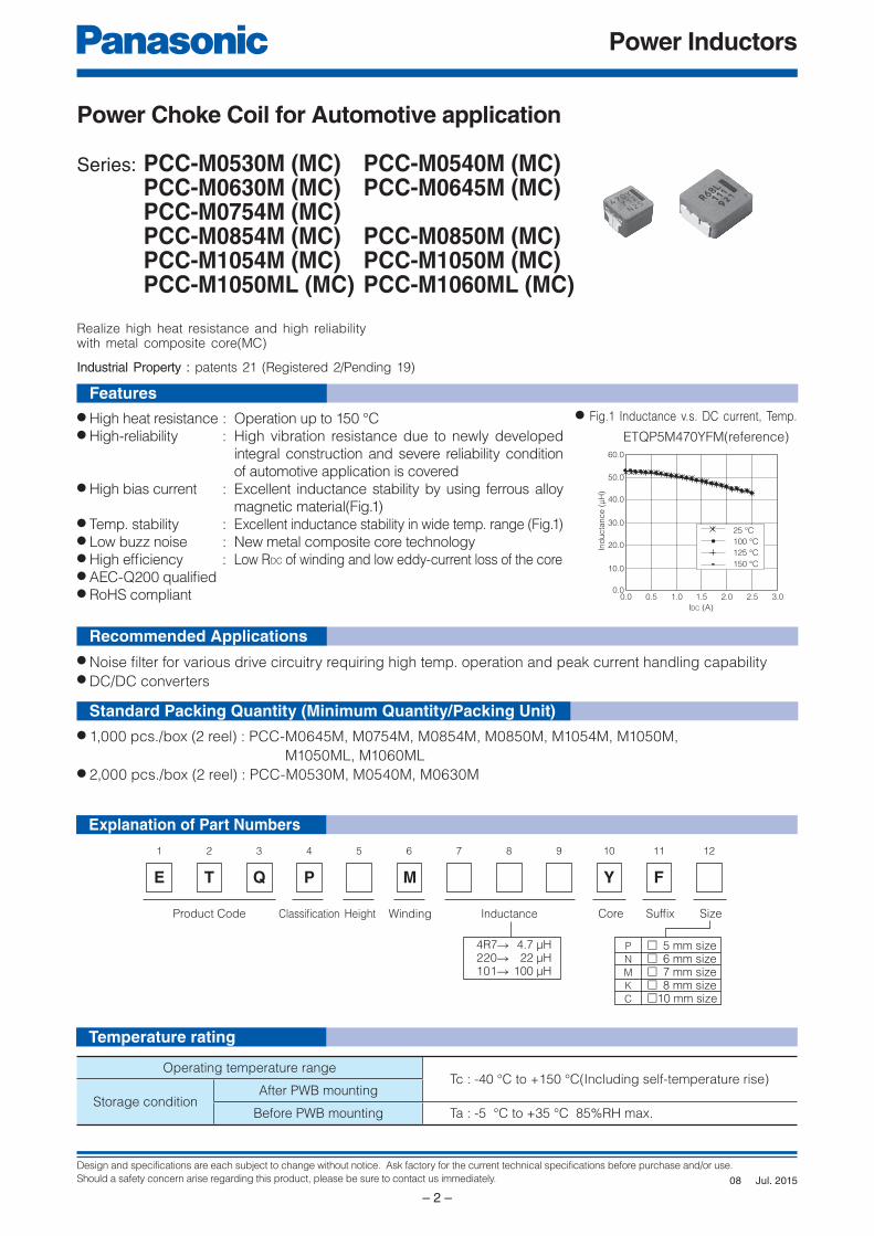
Power Choke Coil for Automotive application
Series: PCC-M0530M (MC) PCC-M0540M (MC) PCC-M0630M (MC) PCC-M0645M (MC) PCC-M0754M (MC) PCC-M0854M (MC) PCC-M0850M (MC) PCC-M1054M (MC) PCC-M1050M (MC) PCC-M1050ML (MC) PCC-M1060ML (MC)
● High heat resistance : Operation up to 150 °C● High-reliability : High vibration resistance due to newly developed
integral construction and severe reliability condition
of automotive application is covered● High bias current : Excellent inductance stability by using ferrous alloy
magnetic material(Fig.1)● Temp. stability : Excellent inductance stability in wide temp. range (Fig.1)● Low buzz noise : New metal composite core technology● High effi ciency : Low RDC of winding and low eddy-current loss of the core● AEC-Q200 qualifi ed● RoHS compliant
● Noise fi lter for various drive circuitry requiring high temp. operation and peak current handling capability● DC/DC converters
● 1,000 pcs./box (2 reel) : PCC- M0645M, M0754M, M0854M, M0850M, M1054M, M1050M,
M1050ML, M1060ML● 2,000 pcs./box (2 reel) : PCC-M0530M, M0540M, M0630M
Explanation of Part Numbers
Temperature rating
Features
Recommended Applications
Standard Packing Quantity (Minimum Quantity/Packing Unit)
Realize high heat resistance and high reliabilitywith metal composite core(MC)
Industrial Property : patents 21 (Registered 2/Pending 19)
ETQP5M470YFM(reference)
● Fig.1 Inductance v.s. DC current, Temp.
Operating temperature rangeTc : -40 °C to +150 °C(Including self-temperature rise)
Storage conditionAfter PWB mounting
Before PWB mounting Ta : -5 °C to +35 °C 85%RH max.
Jul. 201508
Design and specifications are each subject to change without notice. Ask factory for the current technical specifications before purchase and/or use.
Should a safety concern arise regarding this product, please be sure to contact us immediately.
Power Inductors
– 3 –
IDC (A)
Ind
ucta
nce (
µH
)
0
5
10
15
20
30
25
0 1 2 3 4 5
IDC (A)
0.0
0.5
1.0
1.5
2.5
2.0
0 2 4 6 8 1210 14
Ind
ucta
nce (
µH
)
IDC (A)
Ind
ucta
nce (
µH
)
0.0
1.0
2.0
3.0
5.0
4.0
0 2 4 6 8 1210 14
IDC (A)
ΔT(K
)
0
10
20
30
40
50
60
70
80
0 0.5 1 1.5 2 2.5 3 3.5
PWB condition APWB condition B
IDC (A)
0
10
20
30
40
50
60
70
80
0 1 2 3 4 5 76 8
PWB condition APWB condition B
ΔT(K
)
IDC (A)
ΔT(K
)
0
10
20
30
40
50
60
70
80
0 1 2 3 4 5 6 7
PWB condition APWB condition B
IDC (A)
Ind
ucta
nce (
µH
)
0.0
1.0
2.0
3.0
5.0
4.0
0 2 4 6 8 1210 14
IDC (A)
ΔT(K
)
0
10
20
30
40
50
60
70
80
0 1 2 3 4 5 6 7
PWB condition APWB condition B
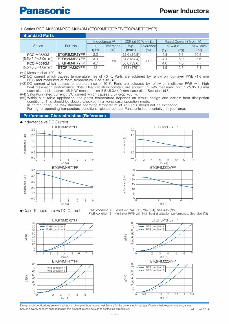
● Inductance vs DC Current
ETQP3M2R2YFP
ETQP4M4R7YFP
1. Series PCC-M0530M/PCC-M0540M (ETQP3M□□□YFP/ETQP4M□□□YFP)
Series Part No.
Inductance ✽1 DCR (at 20 °C) (mΩ) Rated Current (Typ. : A)
L0(µH)
Tolerance(%)
Typ. (max.)
Tolerance(%)
△T=40K △L=–30%
(✽2) (✽3) (✽4)
PCC-M0530M[5.5×5.0×3.0(mm)]
ETQP3M2R2YFP 2.2
±20
22.6 (24.8)
±10
4.8 5.8 10.9
ETQP3M3R3YFP 3.3 31.3 (34.4) 4.1 5.0 8.6
PCC-M0540M[5.5×5.0×4.0(mm)]
ETQP4M4R7YFP 4.7 36.0 (39.6) 4.0 4.8 7.7
ETQP4M220YFP 22 163 (179) 1.9 2.3 3.1
(✽1) Measured at 100 kHz.(✽2) DC current which causes temperature rise of 40 K. Parts are soldered by reflow on four-layer PWB (1.6 mm
FR4) and measured at room temperature. See also (✽5)(✽3) DC current which causes temperature rise of 40 K. Parts are soldered by reflow on multilayer PWB with high
heat dissipation performance. Note: Heat radiation constant are approx. 52 K/W measured on 5.5×5.0×3.0 mm case size and approx. 48 K/W measured on 5.5×5.0×4.0 mm case size. See also (✽5)
(✽4) Saturation rated current : DC current which causes L(0) drop –30 %.(✽5) Within a suitable application, the part’s temperature depends on circuit design and certain heat dissipation
conditions. This should be double checked in a worst case operation mode. In normal case, the max.standard operating temperature of +150 °C should not be exceeded. For higher operating temperature conditions, please contact Panasonic representative in your area.
ETQP4M220YFP
ETQP3M2R2YFP
ETQP4M4R7YFP ETQP4M220YFP
● Case Temperature vs DC Current PWB condition A : Four-layer PWB (1.6 mm FR4), See also (✽2)PWB condition B : Multilayer PWB with high heat dissipation performance. See also (✽3)
ETQP3M3R3YFP
ETQP3M3R3YFP
Standard Parts
Performance Characteristics (Ref er ence)
Jul. 201508
Design and specifications are each subject to change without notice. Ask factory for the current technical specifications before purchase and/or use.
Should a safety concern arise regarding this product, please be sure to contact us immediately.
Power Inductors
– 4 –
0
0.2
0.4
0.6
1
0.8
0 5 10 15 20
IDC (A)
Ind
ucta
nce (
µH
)
IDC (A)
0
4
2
6
8
12
10
0 2 3 41 5 6 7 8 9
Ind
ucta
nce (
µH
)
0
0.1
0.2
0.3
0.4
0.7
0.6
0.5
0 4 8 12 16 20 24
IDC (A)
Ind
ucta
nce (
µH
)
IDC (A)
05
101520253035404550
0 1.5 2.00.5 1.0 2.5 3.0 3.5 4.0 4.5 5.0
Ind
ucta
nce (
µH
)
IDC (A)
0
1
2
3
4
5
6
7
8
0 3 41 2 5 6 7 8 9 10
Ind
ucta
nce (
µH
)
IDC (A)
ΔT
(K)
0
10
20
30
40
50
60
70
80
0 2 4 6 8 10 12 14 16 18
PWB condition APWB condition B
IDC (A)
ΔT
(K)
0
10
20
30
40
50
60
70
80
0 0.5 1.0 1.5 2.0 2.5 3.0
PWB condition APWB condition B
IDC (A)
ΔT
(K)
0
10
20
30
40
50
60
70
80
0 0.5 1 1.5 2 2.5 3 3.5 4 4.5 5.55 6
PWB condition APWB condition B
IDC (A)
ΔT
(K)
0
10
20
30
40
50
60
70
80
0 1 32 4 5 6 7
PWB condition APWB condition B
IDC (A)
ΔT
(K)
0
10
20
30
40
50
60
70
80
0 2 4 6 8 10 12 14 16 18
PWB condition APWB condition B
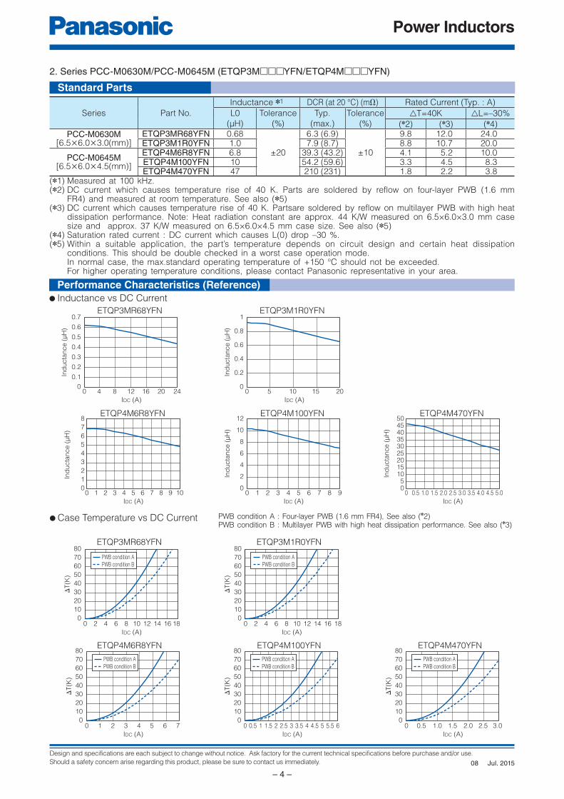
2. Series PCC-M0630M/PCC-M0645M (ETQP3M□□□YFN/ETQP4M□□□YFN)
Series Part No.
Inductance ✽1 DCR (at 20 °C) (mΩ) Rated Current (Typ. : A)
L0
(µH)
Tolerance
(%)
Typ.
(max.)
Tolerance
(%)
△T=40K △L=–30%
(✽2) (✽3) (✽4)PCC-M0630M
[6.5×6.0×3.0(mm)]ETQP3MR68YFN 0.68
±20
6.3 (6.9)
±10
9.8 12.0 24.0ETQP3M1R0YFN 1.0 7.9 (8.7) 8.8 10.7 20.0
PCC-M0645M[6.5×6.0×4.5(mm)]
ETQP4M6R8YFN 6.8 39.3 (43.2) 4.1 5.2 10.0ETQP4M100YFN 10 54.2 (59.6) 3.3 4.5 8.3ETQP4M470YFN 47 210 (231) 1.8 2.2 3.8
(✽1) Measured at 100 kHz.(✽2) DC current which causes temperature rise of 40 K. Parts are soldered by reflow on four-layer PWB (1.6 mm
FR4) and measured at room temperature. See also (✽5)(✽3) DC current which causes temperature rise of 40 K. Partsare soldered by reflow on multilayer PWB with high heat
dissipation performance. Note: Heat radiation constant are approx. 44 K/W measured on 6.5×6.0×3.0 mm case size and approx. 37 K/W measured on 6.5×6.0×4.5 mm case size. See also (✽5)
(✽4) Saturation rated current : DC current which causes L(0) drop –30 %.(✽5) Within a suitable application, the part’s temperature depends on circuit design and certain heat dissipation
conditions. This should be double checked in a worst case operation mode. In normal case, the max.standard operating temperature of +150 °C should not be exceeded. For higher operating temperature conditions, please contact Panasonic representative in your area.
ETQP3MR68YFN ETQP3M1R0YFN
ETQP4M100YFN ETQP4M470YFNETQP4M6R8YFN
ETQP3MR68YFN
ETQP4M100YFN ETQP4M470YFNETQP4M6R8YFN
ETQP3M1R0YFN
Standard Parts
● Inductance vs DC Current
Performance Characteristics (Ref er ence)
● Case Temperature vs DC Current PWB condition A : Four-layer PWB (1.6 mm FR4), See also (✽2)PWB condition B : Multilayer PWB with high heat dissipation performance. See also (✽3)
Jul. 201508
Design and specifications are each subject to change without notice. Ask factory for the current technical specifications before purchase and/or use.
Should a safety concern arise regarding this product, please be sure to contact us immediately.
Power Inductors
– 5 –
IDC (A)
0
2
4
6
8
10
12
0 4 8 12 142 6 10 16
Ind
ucta
nce (
µH
)
IDC (A)
ΔT
(K)
0
10
2030
40
50
60
70
80
0 2 4 6 8 10
PWB condition APWB condition B
Ind
ucta
nce (
µH
)
IDC (A)
0
10
20
30
40
50
60
0 1 2 3 64 5
Ind
ucta
nce (
µH
)
IDC (A)
0
10
20
30
40
0 2 4 6 8
Ind
ucta
nce (
µH
)
IDC (A)
0.0
1.0
2.0
3.0
4.0
5.0
6.0
0 5 10 15 20
IDC (A)
ΔT
(K)
0
10
20
30
40
50
60
70
80
0 1 2 3 4 5
PWB condition APWB condition BPWB condition APWB condition B
IDC (A)
0
10
2030
40
50
60
70
80
0 2 4 6 81 3 5 7
ΔT
(K)
PWB condition APWB condition B
IDC (A)
ΔT
(K)
0
10
2030
40
50
60
70
80
0 1 2 3 4
PWB condition APWB condition B
Ind
ucta
nce (
µH
)
IDC (A)
0
5
10
15
20
25
0 2 4 6 108
IDC (A)
ΔT
(K)
0
10
2030
40
50
60
70
80
0 1 2 3 4 5
PWB condition APWB condition B
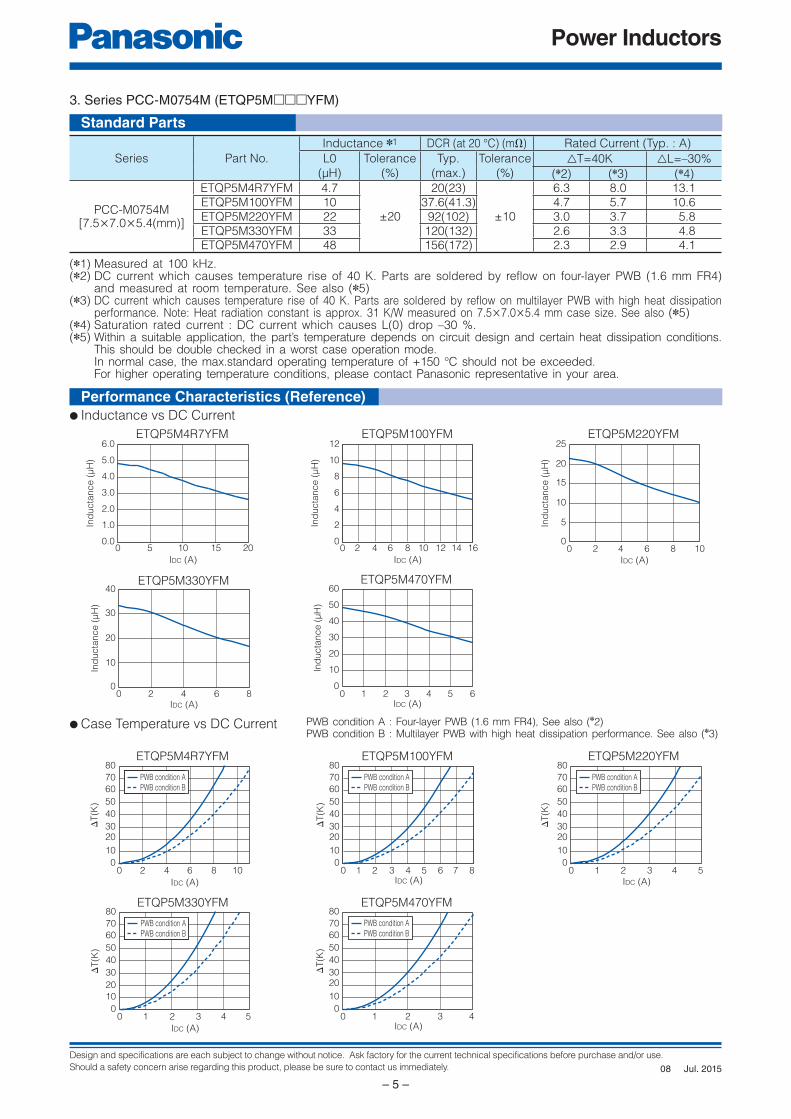
3. Series PCC-M0754M (ETQP5M□□□YFM)
Standard Parts
● Inductance vs DC Current
Performance Characteristics (Ref er ence)
● Case Temperature vs DC Current PWB condition A : Four-layer PWB (1.6 mm FR4), See also (✽2)PWB condition B : Multilayer PWB with high heat dissipation performance. See also (✽3)
ETQP5M4R7YFM ETQP5M100YFM
ETQP5M4R7YFM
(✽1) Measured at 100 kHz.(✽2) DC current which causes temperature rise of 40 K. Parts are soldered by reflow on four-layer PWB (1.6 mm FR4)
and measured at room temperature. See also (✽5)(✽3) DC current which causes temperature rise of 40 K. Parts are soldered by reflow on multilayer PWB with high heat dissipation
performance. Note: Heat radiation constant is approx. 31 K/W measured on 7.5×7.0×5.4 mm case size. See also (✽5)(✽4) Saturation rated current : DC current which causes L(0) drop –30 %.(✽5) Within a suitable application, the part’s temperature depends on circuit design and certain heat dissipation conditions.
This should be double checked in a worst case operation mode. In normal case, the max.standard operating temperature of +150 °C should not be exceeded. For higher operating temperature conditions, please contact Panasonic representative in your area.
ETQP5M330YFM ETQP5M470YFM
ETQP5M100YFM
ETQP5M330YFM ETQP5M470YFM
Series Part No.
Inductance ✽1 DCR (at 20 °C) (mΩ) Rated Current (Typ. : A)
L0
(µH)
Tolerance
(%)
Typ.
(max.)
Tolerance
(%)
△T=40K △L=–30%
(✽2) (✽3) (✽4)
PCC-M0754M[7.5×7.0×5.4(mm)]
ETQP5M4R7YFM 4.7
±20
20(23)
±10
6.3 8.0 13.1ETQP5M100YFM 10 37.6(41.3) 4.7 5.7 10.6ETQP5M220YFM 22 92(102) 3.0 3.7 5.8ETQP5M330YFM 33 120(132) 2.6 3.3 4.8ETQP5M470YFM 48 156(172) 2.3 2.9 4.1
ETQP5M220YFM
ETQP5M220YFM
Jul. 201508
Design and specifications are each subject to change without notice. Ask factory for the current technical specifications before purchase and/or use.
Should a safety concern arise regarding this product, please be sure to contact us immediately.
Power Inductors
– 6 –
Ind
ucta
nce (
µH
)
IDC (A)
0
2
4
6
8
10
12
0 42 6 8 1610 12 14
IDC (A)
0
10
2030
40
50
60
70
80
0 4 8 12 16 20
ΔT
(K)
PWB condition APWB condition BPWB condition APWB condition B
Ind
ucta
nce (
µH
)
IDC (A)
0.0
0.5
1.0
1.5
2.0
2.5
3.0
0 5 1510 2520 30
IDC (A)
ΔT
(K)
0
10
2030
40
50
60
70
80
0 2 4 6 8 10
PWB condition APWB condition B
IDC (A)
ΔT
(K)
0
10
2030
40
50
60
70
80
0 0.5 1.0 1.5 2.0 2.5 3.0
PWB condition APWB condition B
IDC (A)
ΔT
(K)
0
10
2030
40
50
60
70
80
0 1 2 3 4 5
PWB condition APWB condition B
IDC (A)
ΔT
(K)
0
10
2030
40
50
60
70
80
0 1 2 3 4 5 6 7
PWB condition APWB condition B
Ind
ucta
nce (
µH
)
IDC (A)
0
20
40
60
80
100
120
0 1 2 53 4
Ind
ucta
nce (
µH
)
IDC (A)
0
10
20
30
60
40
50
0 2 4 6 8
Ind
ucta
nce
(μH
)
IDC (A)
0
5
10
15
20
25
0 2 4 6 108
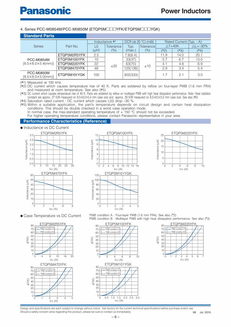
4. Series PCC-M0854M/PCC-M0850M (ETQP5M□□□YFK/ETQP5M□□□YGK)
Standard Parts
ETQP5M2R5YFK ETQP5M100YFK
ETQP5M2R5YFK ETQP5M100YFK
ETQP5M101YGKETQP5M470YFK
ETQP5M220YFK
ETQP5M101YGKETQP5M470YFK
ETQP5M220YFK
(✽1) Measured at 100 kHz.(✽2) DC current which causes temperature rise of 40 K. Parts are soldered by reflow on four-layer PWB (1.6 mm FR4)
and measured at room temperature. See also (✽5)(✽3) DC current which causes temperature rise of 40 K. Parts are soldered by reflow on multilayer PWB with high heat dissipation performance. Note: Heat radiation
constant are approx. 27 K/W measured on 8.5×8.0×5.4 mm case size and approx. 29 K/W measured on 8.5×8.0×5.0 mm case size. See also (✽5)(✽4) Saturation rated current : DC current which causes L(0) drop –30 %.(✽5) Within a suitable application, the part’s temperature depends on circuit design and certain heat dissipation
conditions. This should be double checked in a worst case operation mode. In normal case, the max.standard operating temperature of + 150 °C should not be exceeded. For higher operating temperature conditions, please contact Panasonic representative in your area.
Series Part No.
Inductance ✽1 DCR (at 20 °C) (mΩ) Rated Current (Typ. : A)
L0(µH)
Tolerance(%)
Typ. (max.)
Tolerance(%)
△T=40K △L=–30%
(✽2) (✽3) (✽4)
PCC-M0854M[8.5×8.0×5.4(mm)]
ETQP5M2R5YFK 2.5
±20
7.6(8.4)
±10
11.9 14.0 20.1
ETQP5M100YFK 10 33(37) 5.7 6.7 13.0
ETQP5M220YFK 22 63(70) 4.1 4.8 6.9
ETQP5M470YFK 48 125(138) 2.9 3.4 5.4
PCC-M0850M[8.5×8.0×5.0(mm)]
ETQP5M101YGK 100 302(333) 1.7 2.1 3.0
Performance Characteristics (Ref er ence)
● Case Temperature vs DC Current PWB condition A : Four-layer PWB (1.6 mm FR4), See also (✽2)PWB condition B : Multilayer PWB with high heat dissipation performance. See also (✽3)
● Inductance vs DC Current
Jul. 201508
Design and specifications are each subject to change without notice. Ask factory for the current technical specifications before purchase and/or use.
Should a safety concern arise regarding this product, please be sure to contact us immediately.
Power Inductors
– 7 –
Ind
ucta
nce (
µH
)
IDC (A)
0
1
2
3
4
0 5 10 15 20 3025
Ind
ucta
nce (
µH
)
IDC (A)
0
1
2
3
5
4
6
0 5 10 15 20
Ind
ucta
nce (
µH
)
IDC (A)
0
5
10
15
20
25
0 2 4 6 108
Ind
ucta
nce (
µH
)
IDC (A)
0
2
4
6
8
10
12
0 2 4 6 8 1610 12 14
Ind
ucta
nce (
µH
)
IDC (A)
0.0
0.5
1.0
1.5
2.0
2.5
3.0
0 10 20 30 40
IDC (A)
0
10
20
30
40
0 2 4 6 8 10
Ind
ucta
nce (
µH
)
Ind
ucta
nce (
µH
)
IDC (A)
0
20
40
60
80
100
120
0 1 2 3 4 65 7
IDC (A)
0
0.4
0.8
1.2
1.6
0 10 20 30 40
Ind
ucta
nce (
µH
)
Standard Parts
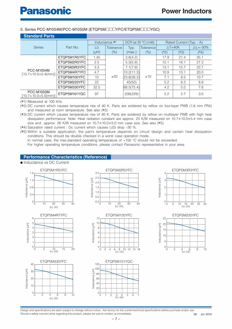
5. Series PCC-M1054M/PCC-M1050M (ETQP5M□□□YFC/ETQP5M□□□YGC)
(✽1) Measured at 100 kHz.
(✽2) DC current which causes temperature rise of 40 K. Parts are soldered by reflow on four-layer PWB (1.6 mm FR4)
and measured at room temperature. See also (✽5)
(✽3) DC current which causes temperature rise of 40 K. Parts are soldered by reflow on multilayer PWB with high heat
dissipation performance. Note: Heat radiation constant are approx. 23 K/W measured on 10.7×10.0×5.4 mm case
size and approx. 26 K/W measured on 10.7×10.0×5.0 mm case size. See also (✽5)
(✽4) Saturation rated current : Dc current which causes L(0) drop –30 %.
(✽5) Within a suitable application, the part’s temperature depends on circuit design and certain heat dissipation
conditions. This should be double checked in a worst case operation mode.
In normal case, the max.standard operating temperature of +150 °C should not be exceeded.
For higher operating temperature conditions, please contact Panasonic representative in your area.
ETQP5M3R3YFC
ETQP5M4R7YFC
ETQP5M330YFC
ETQP5M220YFC
Series Part No.
Inductance ✽1 DCR (at 20 °C) (mΩ) Rated Current (Typ. : A)
L0
(µH)
Tolerance
(%)
Typ.
(max.)
Tolerance
(%)
△T=40K △L=–30%
(✽2) (✽3) (✽4)
PCC-M1054M[10.7×10.0×5.4(mm)]
ETQP5M1R5YFC 1.45
±20
3.8(4.2)
±10
17.9 21.4 35.1
ETQP5M2R5YFC 2.5 5.3(5.9) 15.1 18.1 27.2
ETQP5M3R3YFC 3.3 7.1(7.9) 13.1 15.7 22.7
ETQP5M4R7YFC 4.7 10.2(11.3) 10.9 13.1 20.0
ETQP5M100YFC 10 23.8(26.2) 7.1 8.5 10.7
ETQP5M220YFC 22 45(50) 5.2 6.2 8.8
ETQP5M330YFC 32.5 68.5(75.4) 4.2 5.0 7.6
PCC-M1050M[10.7×10.0×5.0(mm)]
ETQP5M101YGC 97 208(229) 2.2 2.7 3.0
ETQP5M2R5YFC
ETQP5M100YFC
ETQP5M101YGC
ETQP5M1R5YFC
● Inductance vs DC Current
Performance Characteristics (Ref er ence)
Jul. 201508
Design and specifications are each subject to change without notice. Ask factory for the current technical specifications before purchase and/or use.
Should a safety concern arise regarding this product, please be sure to contact us immediately.
Power Inductors
– 8 –
IDC (A)
0
10
2030
40
50
60
70
80
0 5 10 15 20 25
ΔT
(K)
PWB condition APWB condition B
IDC (A)
ΔT
(K)
0
10
2030
40
50
60
70
80
0 4 8 12 2016
PWB condition APWB condition B
IDC (A)
ΔT
(K)
0
10
2030
40
50
60
70
80
0 4 8 12 16 2420
PWB condition APWB condition B
IDC (A)
ΔT
(K)
0
10
2030
40
50
60
70
80
0 2 4 6 8 1210
PWB condition APWB condition B
IDC (A)
ΔT
(K)
0
10
2030
40
50
60
70
80
0 2 4 6 8 10
PWB condition APWB condition B
IDC (A)
0
10
2030
40
50
60
70
80
0 1 2 43 65 7
ΔT
(K)
PWB condition APWB condition B
IDC (A)
ΔT
(K)
0
10
2030
40
50
60
70
80
0 0.5 1.0 1.5 2.0 2.5 4.03.0 3.5
PWB condition APWB condition B
IDC (A)
ΔT
(K)
0
10
2030
40
50
60
70
80
0 5 10 2015 25 30
PWB condition APWB condition B
ETQP5M2R5YFC ETQP5M3R3YFC
ETQP5M4R7YFC ETQP5M100YFC ETQP5M220YFC
ETQP5M330YFC ETQP5M101YGC
ETQP5M1R5YFC
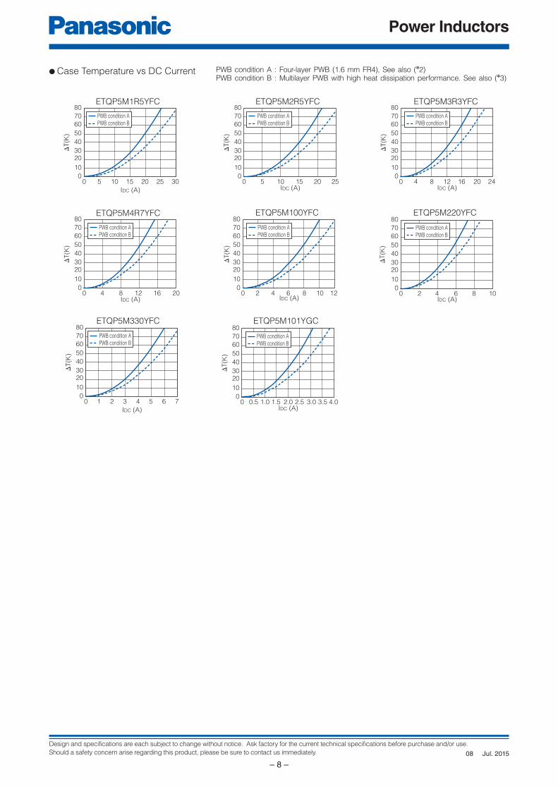
● Case Temperature vs DC Current PWB condition A : Four-layer PWB (1.6 mm FR4), See also (✽2)PWB condition B : Multilayer PWB with high heat dissipation performance. See also (✽3)
Jul. 201508
Design and specifications are each subject to change without notice. Ask factory for the current technical specifications before purchase and/or use.
Should a safety concern arise regarding this product, please be sure to contact us immediately.
Power Inductors
– 9 –
Ind
ucta
nce (
µH
)
IDC (A)
0.0
0.1
0.2
0.3
0.4
0.5
0.7
0.6
0 10 20 30 40 50 60
IDC (A)
0
10
2030
40
50
60
70
80
0 5 10 15 20 25 30 35
PWB condition APWB condition B
ΔT
(K)
IDC (A)
0.0
0.2
0.4
0.6
0.8
1.2
1.0
0 10 20 30 40 50 60
Ind
ucta
nce (
µH
)
IDC (A)
ΔT
(K)
0
10
2030
40
50
60
70
80
0 5 10 15 20 25 30 35 40 45
PWB condition APWB condition B
Ind
ucta
nce (
µH
)
IDC (A)
0.0
0.5
1.0
1.5
2.0
2.5
3.0
0 10 20 30 40
IDC (A)
ΔT
(K)
0
10
2030
40
50
60
70
80
0 4 8 12 16 20 24 28
PWB condition APWB condition B
0.0
0.5
1.0
1.5
2.0
2.5
3.5
3.0
0 5 1510 20 25 30 35 40
Ind
ucta
nce (
µH
)
IDC (A)
IDC (A)
0
10
2030
40
50
60
70
80
0 5 10 15 20 25
ΔT
(K)
PWB condition APWB condition B
(✽1) Measured at 100 kHz.(✽2) DC current which causes temperature rise of 40 K. Parts are soldered by reflow on four-layer PWB (1.6 mm FR4)
and measured at room temperature. See also (✽5)(✽3) DC current which causes temperature rise of 40 K. Parts are soldered by reflow on multilayer PWB with high heat
dissipation performance. Note: Heat radiation constant are approx. 23 K/W measured on 10.9×10.0×5.0 mm case size and approx. 23 K/W measured on 10.9×10.0×6.0 mm case size. See also (✽5)
(✽4) Saturation rated current : Dc current which causes L(0) drop –30 %.(✽5) Within a suitable application, the part’s temperature depends on circuit design and certain heat dissipation
conditions. This should be double checked in a worst case operation mode. In normal case, the max.standard operating temperature of +150 °C should not be exceeded. For higher operating temperature conditions, please contact Panasonic representative in your area.
Series Part No.
Inductance ✽1 DCR (at 20 °C) (mΩ) Rated Current (Typ. : A)
L0
(µH)
Tolerance
(%)
Typ.
(max.)
Tolerance
(%)
△T=40K △L=–30%
(✽2) (✽3) (✽4)
PCC-M1050ML[10.9×10.0×5.0(mm)]
ETQP5MR68YLC 0.68
±20
1.75(1.93)
±10
26.3 31.5 42.0
ETQP5M1R0YLC 1.0 2.3(2.53) 23.0 27.5 38
PCC-M1060ML[10.9×10.0×6.0(mm)]
ETQP6M2R5YLC 2.5 4.5(5.0) 16.3 19.6 27.0
ETQP6M3R3YLC 3.3 6.0(6.6) 14.2 17.0 26.0
ETQP5MR68YLC ETQP5M1R0YLC
ETQP5MR68YLC ETQP5M1R0YLC
ETQP6M2R5YLC ETQP6M3R3YLC
ETQP6M2R5YLC ETQP6M3R3YLC
Standard Parts
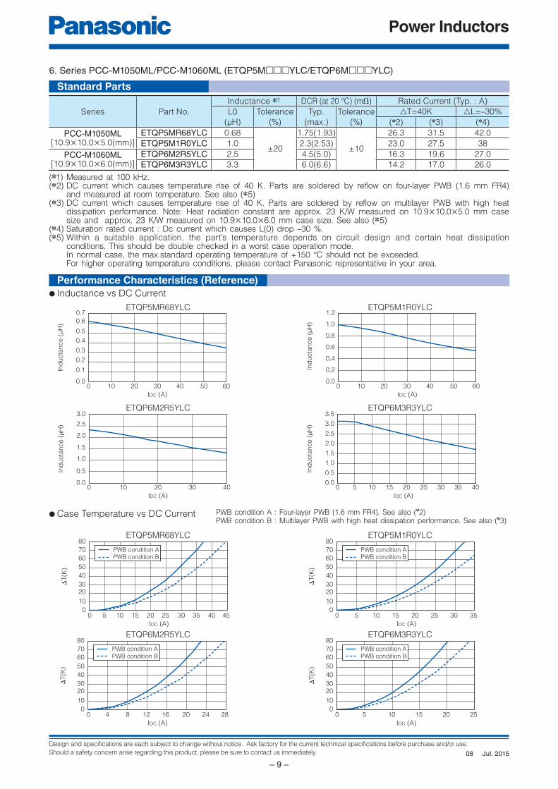
6. Series PCC-M1050ML/PCC-M1060ML (ETQP5M□□□YLC/ETQP6M□□□YLC)
● Case Temperature vs DC Current PWB condition A : Four-layer PWB (1.6 mm FR4), See also (✽2)PWB condition B : Multilayer PWB with high heat dissipation performance. See also (✽3)
● Inductance vs DC Current
Performance Characteristics (Ref er ence)
Jul. 201508

Design and specifications are each subject to change without notice. Ask factory for the current technical specifications before purchase and/or use.
Should a safety concern arise regarding this product, please be sure to contact us immediately.
Power Inductors
– 10 –
Date Code Polarity
Inductance Suffix
7.5±0.4
7.0
±0.4
3.0±
0.3
2.0 2.0
5.4
max.
0.1
min
.
Date Code Polarity
Inductance Suffix
8.5±0.4
H
0.1
min
.
2.02.0
3.0±
0.3
8.0
±0.4
Date Code Polarity
Inductance Suffix
10.7±0.5
10.0
±0.4
4.2
±0.3
2.0 2.0
H
0.1
min
.
Date Code Polarity
Inductance Suffix
10.9±0.6
10.0
±0.4
7.3
±0.3
1.8 1.8
H
0.5
min
.
Date Code Polarity
Inductance Suffix
5.5±0.4
5.0
±0
.4
3.0
±0
.3
1.21.2
H
0.1
min
.
Date Code Polarity
Inductance Suffix
6.5±0.4
6.0
±0
.4
3.0
±0
.3
1.5 1.5
H
0.1
min
.
Series PCC-M0754M(ETQP5M□□□YFM)
Series PCC-M0854MSeries PCC-M0850M
(ETQP5M□□□YFK/YGK)
Series PCC-M1054MSeries PCC-M1050M
(ETQP5M□□□YFC/YGC)
Series H
M1054M 5.4 max.
M1050M 5.0 max.
Series H
M0854M 5.4 max.
M0850M 5.0 max.
Series PCC-M1050MLSeries PCC-M1060ML
(ETQP5M□□□YLC/ETQP6M□□□YLC)
Series H
M1050ML 5.0 max.
M1060ML 6.0 max.
Series PCC-M0530MSeries PCC-M0540M
(ETQP3M□□□YFP/ETQP4M□□□YFP)
Series PCC-M0630MSeries PCC-M0645M
(ETQP3M□□□YFN/ETQP4M□□□YFN)
Series H
M0630M 3.0 max.
M0645M 4.5 max.
Series H
M0530M 3.0 max.
M0540M 4.0 max.
Dimensional tolerance unless noted : ±0.5
Dimensions in mm (not to scale)
Jul. 201508

Design and specifications are each subject to change without notice. Ask factory for the current technical specifications before purchase and/or use.
Should a safety concern arise regarding this product, please be sure to contact us immediately.
Power Inductors
– 11 –
Don't wire on the pattern
on shaded portion the PWB.
The same as the left. The same as the left.
6.1
2.2
7.2
3.6
6.0
7.1
2.8
8.8
3.6
7.0
8.4
2.8
10.0
3.6
8.0
Don't wire on the pattern
on shaded portion the PWB.
The same as the left. The same as the left.
9.4 11.7
6.1
13.7
3.8
12.4
4.0
4.8 11
9.0
11.9
6.5
13.9
7.9 11
Series PCC-M0530MSeries PCC-M0540M
(ETQP3M□□□YFP/ETQP4M□□□YFP)
Series PCC-M0630MSeries PCC-M0645M
(ETQP3M□□□YFN/ETQP4M□□□YFN)
Series PCC-M0754M(ETQP5M□□□YFM)
Series PCC-M0854MSeries PCC-M0850M
(ETQP5M□□□YFK/YGK)
Series PCC-M1054MSeries PCC-M1050M
(ETQP5M□□□YFC/YGC)
Series PCC-M1050MLSeries PCC-M1060ML
(ETQP5M□□□YLC/ETQP6M□□□YLC)
Dimensional tolerance unless noted : ±0.5
Recommended Land Pattern in mm (not to scale)
■ As for Packaging Methods, Soldering Conditions and Safety Precautions (Power Choke Coils for Automotive application), Please see Data Files
Jul. 201508
Design and specifications are each subject to change without notice. Ask factory for the current technical specifications before purchase and/or use.
Should a safety concern arise regarding this product, please be sure to contact us immediately.
Power Inductors
– 12 –
E
1 2
Q
3
P H D
4 5 6 7 8 9
Product Code InductanceClassification
10 11 12
SizeSuffixCoreWindingHeight
T
Explanation of Part Numbers
Features
Recommended Applications
Standard Packing Quantity
● High heat resistance : Operation up to 150 °C● SMD and small package : L×W×T=14.7×13.2×13.1 mm● High-reliability : High vibration resistance due to newly developed integral construction and severe
reliability condition of automotive application is covered● High bias current : Excellent inductance stability by using ferrous alloy magnetic material● High Vibration proof : 5 Hz to 2 kHz/30 G● High effi ciency : Achieve by Low loss Dust core and Edgewise coil with rectangular wire● AEC-Q200 qualifi ed● RoHS compliant
● Driver circuits of fuel injection systems in automotive, driver circuits of diesel common rail injection, step-up power supplies for motor driver-circuits
● 600 pcs./10 tray
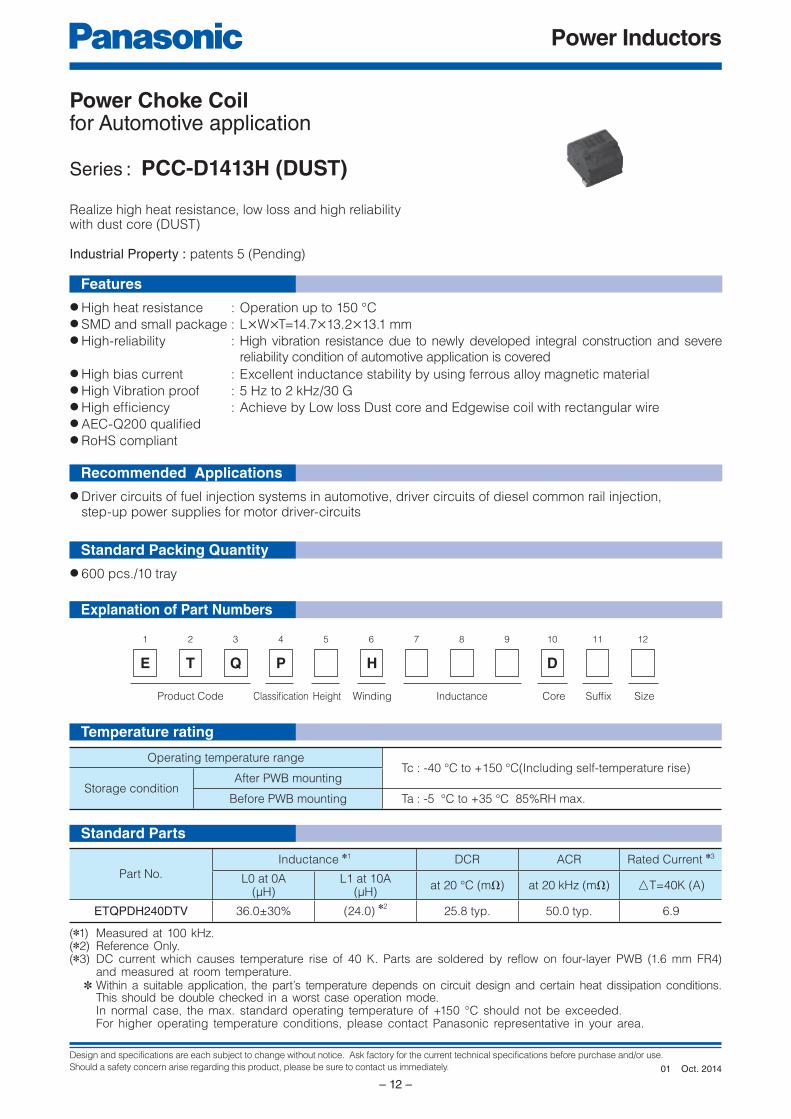
Power Choke Coil for Automotive application
Series : PCC-D1413H (DUST)
Operating temperature rangeTc : -40 °C to +150 °C(Including self-temperature rise)
Storage conditionAfter PWB mounting
Before PWB mounting Ta : -5 °C to +35 °C 85%RH max.
Realize high heat resistance, low loss and high reliabilitywith dust core (DUST)
Industrial Property : patents 5 (Pending)
Part No.
Inductance ✽1 DCR ACR Rated Current ✽3
L0 at 0A(µH)
L1 at 10A(µH)
at 20 °C (mΩ) at 20 kHz (mΩ) △T=40K (A)
ETQPDH240DTV 36.0±30% (24.0) ✽2
25.8 typ. 50.0 typ. 6.9
(✽1) Measured at 100 kHz.(✽2) Reference Only.(✽3) DC current which causes temperature rise of 40 K. Parts are soldered by reflow on four-layer PWB (1.6 mm FR4)
and measured at room temperature. ✽ Within a suitable application, the part’s temperature depends on circuit design and certain heat dissipation conditions.
This should be double checked in a worst case operation mode. In normal case, the max. standard operating temperature of +150 °C should not be exceeded. For higher operating temperature conditions, please contact Panasonic representative in your area.
Standard Parts
Temperature rating
Oct. 201401
Design and specifications are each subject to change without notice. Ask factory for the current technical specifications before purchase and/or use.
Should a safety concern arise regarding this product, please be sure to contact us immediately.
Power Inductors
– 13 –
20.6
10.35 10.35
1.9
4.4
58.4
Recommend
Resist opening area
Recommend
copper pad area
✽ Due to bigger part, Thermal Capacity is large and may
occure PWB temperature differences during reflow
process.
Recommended land pattern (Heat absorb) should be
designed with reflow mountablity.
P2
P1
✽ None polar character
12.6
14.7
13.2±0.6
10.53P1
P2 10.53 2.4
5
2.4
5
5.9
13.1
6.7
min
.
Date Code
InductanceSuffix
0 2 4 6 108 12 14 16 2018
IDC (A)
0 1 2 43 5 6 7 8 9 10
IDC (A)
0
5
10
15
20
30
25
35
40
45
50
(uH)
0
10
20
30
40
50
60
70
80
90
100
ΔT
(K)
Inductance
(µ
H)
Connection Dimensional tolerance unless noted : ±0.5
Dimensional tolerance unless noted : ±0.5
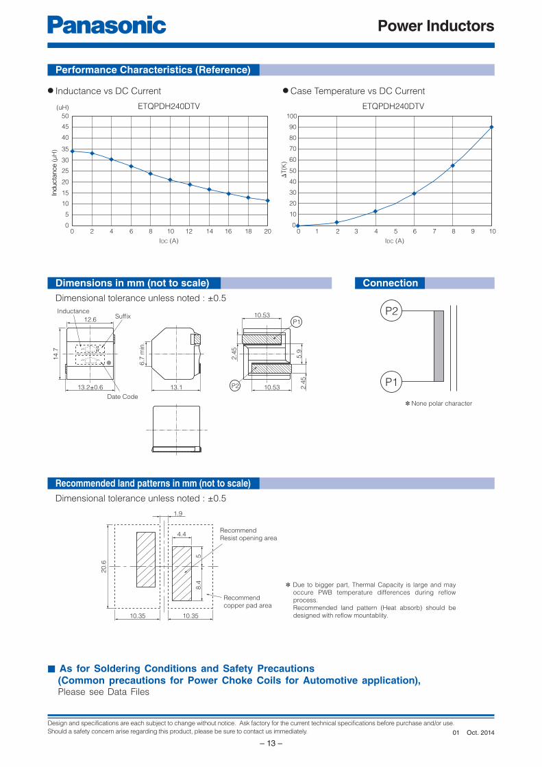
● Inductance vs DC Current ● Case Temperature vs DC Current
ETQPDH240DTVETQPDH240DTV
Performance Characteristics (Reference)
Dimensions in mm (not to scale)
Recommended land patterns in mm (not to scale)
■ As for Soldering Conditions and Safety Precautions (Common precautions for Power Choke Coils for Automotive application), Please see Data Files
Oct. 201401
Design and specifications are each subject to change without notice. Ask factory for the current technical specifications before purchase and/or use.
Should a safety concern arise regarding this product, please be sure to contact us immediately.
Power Inductors
– 14 –
A
B G
E
D
F
C
Terminals
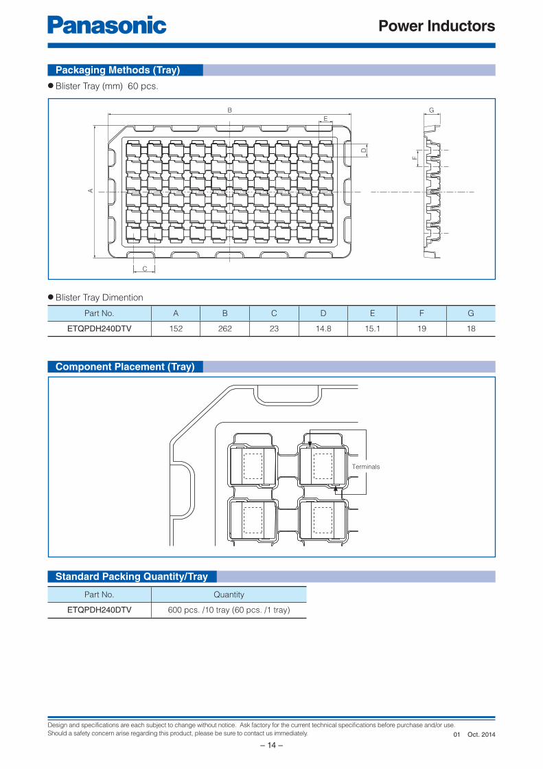
Packaging Methods (Tray)
Component Placement (Tray)
Standard Packing Quantity/Tray
● Blister Tray (mm) 60 pcs.
Part No. A B C D E F G
ETQPDH240DTV 152 262 23 14.8 15.1 19 18
● Blister Tray Dimention
Part No. Quantity
ETQPDH240DTV 600 pcs. /10 tray (60 pcs. /1 tray)
Oct. 201401
Design and specifications are each subject to change without notice. Ask factory for the current technical specifications before purchase and/or use.
Should a safety concern arise regarding this product, please be sure to contact us immediately.
Power Inductors
– 15 –
E
1 2
Q
3
P 3 L X F
4 5 6 7 8 9
Product Code InductanceClassification
10 11
N
12
SuffixPackagingCoreWindingSize
T
E
1 2
Q
3
P 3 M Y F
4 5 6 7 8 9
Product Code InductanceClassification
10 11
N
12
SuffixPackagingCoreWindingSize
T
Explanation of Part Numbers
Features
Recommended Applications
Standard Packing Quantity (Minimum Quantity/Packing Unit)
● Downsize circuit space due to small and low profi le package size● Excellent DC bias performance and high reliability under high humidity● Reduce number of components by high power and low loss● Realize excellent performance by capability to high frequency range● Low buzz noise● RoHS compliant
● Servers, Routers, DC/DC converters for driving CPUs● Laptop and desktop PC power supply● Power supply modules
● 2,000 pcs./box (2 reel)
Power Choke Coil
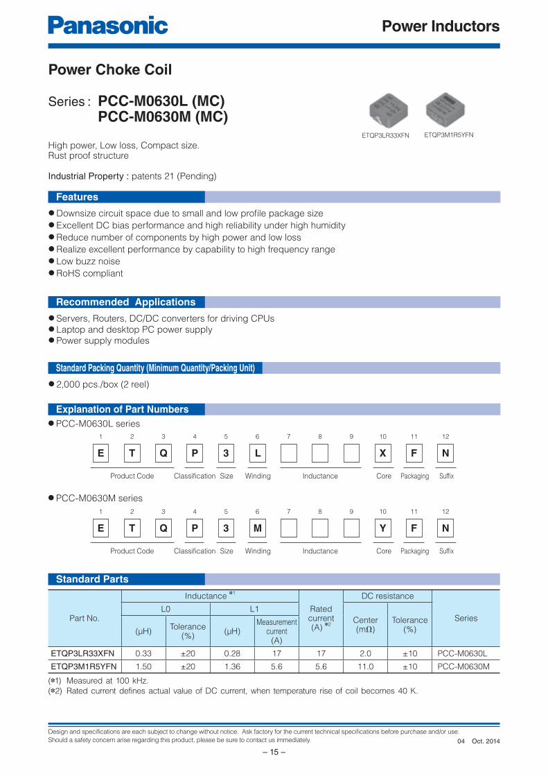
Series : PCC-M0630L (MC) PCC-M0630M (MC)
High power, Low loss, Compact size. Rust proof structure
Industrial Property : patents 21 (Pending)
(✽1) Measured at 100 kHz.
(✽2) Rated current defines actual value of DC current, when temperature rise of coil becomes 40 K.
Standard Parts
● PCC-M0630L series
ETQP3LR33XFN ETQP3M1R5YFN
Part No.
Inductance ✽1
Rated current(A)
✽2
DC resistance
SeriesL0 L1
Center(mΩ)
Tolerance(%)(μH)
Tolerance(%)
(μH)Measurement
current(A)
ETQP3LR33XFN 0.33 ±20 0.28 17 17 2.0 ±10 PCC-M0630L
ETQP3M1R5YFN 1.50 ±20 1.36 5.6 5.6 11.0 ±10 PCC-M0630M
● PCC-M0630M series
Oct. 201404
Design and specifications are each subject to change without notice. Ask factory for the current technical specifications before purchase and/or use.
Should a safety concern arise regarding this product, please be sure to contact us immediately.
Power Inductors
– 16 –
Not to contact the PWB. Not to contact the PWB.
7.5
3.3
9.5
3.6
7.5
7.1
2.8
8.8
3.6
7.0
0.0
0.1
0.2
0.3
Ind
uc
tan
ce
(μ
H)
DC Bias (A)
0.4
0.5
0 5 10 15 20
DC Bias (A)
ΔT(K
)
0
10
20
30
40
50
60
70
80
0 5 10 15 20 250.0
0.4
0.8
1.2
Ind
uc
tan
ce
(μ
H)
DC Bias (A)
1.6
2.0
0 5 10 15 20
DC Bias (A)
ΔT
(K)
0
10
20
30
40
50
60
70
80
0 2 4 6 8 10
PWB condition A
PWB condition B
Data Code Marking of Polarity
Inductance6.5±0.4
6.0
±0.4
3.0±
0.3
1.51.5
P1 P2
3.0
max.
0.05
min
.
Data Code
Inductance7.5±0.4
6.5
±0.3
3.0
±0.3
1.81.8
P1 P2
3.0 max.
0.01 min.
P2
P1
Connection
Performance Characteristics (Reference)
Dimensions in mm (not to scale)
Recommended land patterns in mm (not to scale)
■ As for Packaging Methods, Soldering Conditions and Safety Precautions (Automotive application : PCC-M0630M, Consumer use : PCC-M0630L) Please see Data Files
PCC-M0630L (MC)(ETQP3LR33XFN)
PCC-M0630M (MC)(ETQP3M1R5YFN)
PCC-M0630L (MC)(ETQP3LR33XFN)
PCC-M0630M (MC)(ETQP3M1R5YFN)
● Inductance vs DC Current
● Case Temperature vs DC Current
ETQP3LR33XFN
● PCC-M0630M (MC)
● Inductance vs DC Current
ETQP3M1R5YFN ETQP3M1R5YFNETQP3LR33XFN
● PCC-M0630L (MC)
● Case Temperature vs DC Current✽
PWB condition A : FR4, single layer PWB, t=1.6mm ✽our specification
PWB condition B : FR4, four layer PWB, t=1.6mm
✽ Our temperature rise is specified with measurement of single layer PWB(condition A). Please refer to temperature rise curve V.S. current for the rated current
(ΔT=15K) and Reference value (ΔT=40K). and when four layer PWB (condition B) is used, temperature rise is different from single layer PWB (conditionA).
Even we specify the rated current at our condition, the actual temperature rise of PCC may have different result due to thermal
dissipation condition. We recommend customers to measure PCC temperature rise at application to confirm it.
Oct. 201404
Design and specifications are each subject to change without notice. Ask factory for the current technical specifications before purchase and/or use.
Should a safety concern arise regarding this product, please be sure to contact us immediately.
Power Inductors
– 17 –
E
1 2
Q
3
P 1 W
4 5 6 7 8 9
Product Code InductanceClassification
10 11 12
SuffixPackagingCoreWindingSize
T
Explanation of Part Numbers
Features
Recommended Applications
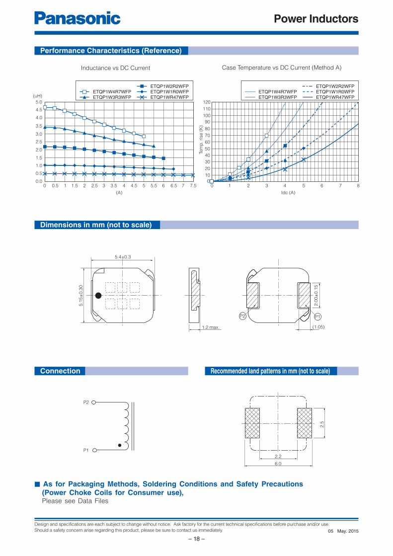
● Small type (5.4×5.15×H1.2 mm)● High power (2.2 A to 5.5 A)● Low loss (RDC :19.2 to 168.0 mΩ)● Suitable for high frequency circuit (up to 1 MHz)● Low buzz noise due to its gap-less structure● RoHS compliant
● HDD, Tablet PC power supply modules● Servers, Routers, DC/DC converters for driving CPUs
● 6,000 pcs./box (2 reel)
Power Choke Coil
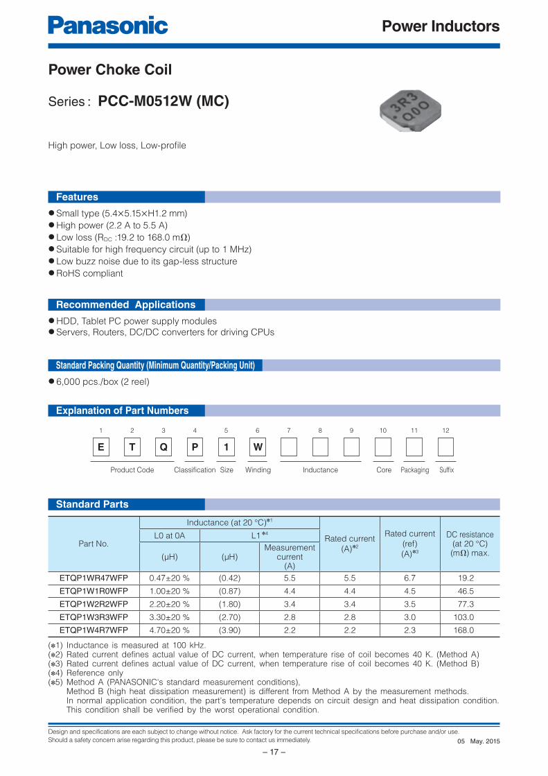
Series : PCC-M0512W (MC)
High power, Low loss, Low-profi le
Standard Parts
(✽1) Inductance is measured at 100 kHz.(✽2) Rated current defines actual value of DC current, when temperature rise of coil becomes 40 K. (Method A)(✽3) Rated current defines actual value of DC current, when temperature rise of coil becomes 40 K. (Method B)(✽4) Reference only(✽5) Method A (PANASONIC's standard measurement conditions), Method B (high heat dissipation measurement) is different from Method A by the measurement methods. In normal application condition, the part's temperature depends on circuit design and heat dissipation condition. This condition shall be verified by the worst operational condition.
Part No.
Inductance (at 20 °C)✽1
Rated current
(A)✽2
Rated current
(ref)
(A)✽3
DC resistance(at 20 °C)(mΩ) max.
L0 at 0A L1 ✽4
(μH) (μH)Measurement
current(A)
ETQP1WR47WFP 0.47±20 % (0.42) 5.5 5.5 6.7 19.2
ETQP1W1R0WFP 1.00±20 % (0.87) 4.4 4.4 4.5 46.5
ETQP1W2R2WFP 2.20±20 % (1.80) 3.4 3.4 3.5 77.3
ETQP1W3R3WFP 3.30±20 % (2.70) 2.8 2.8 3.0 103.0
ETQP1W4R7WFP 4.70±20 % (3.90) 2.2 2.2 2.3 168.0
Standard Packing Quantity (Minimum Quantity/Packing Unit)
May. 201505
Design and specifications are each subject to change without notice. Ask factory for the current technical specifications before purchase and/or use.
Should a safety concern arise regarding this product, please be sure to contact us immediately.
Power Inductors
– 18 –
P2
P1
5.4±0.3
1.2 max.
5.1
5±
0.3
0
(1.05)
2.0
0±
0.1
5P2 P1
2.2
6.0
2.5
0.0
0.5
1.0
1.5
2.0
3.0
2.5
3.5
4.0
4.5
5.0
0 1 1.50.5 2 2.5 3 3.5 4.54 5 5.5 6 6.5 7.57
(A)
(uH)
0
10
20
30
40
50
60
70
80
90
120
110
100
0 1 2 43 5 6 7 8
Idc (A)
Tem
p. rise
(K
)
ETQP1WR47WFP
ETQP1W2R2WFPETQP1W1R0WFP
ETQP1W3R3WFPETQP1W4R7WFP
ETQP1WR47WFP
ETQP1W2R2WFPETQP1W1R0WFP
ETQP1W3R3WFPETQP1W4R7WFP
Connection
Performance Characteristics (Reference)
Dimensions in mm (not to scale)
■ As for Packaging Methods, Soldering Conditions and Safety Precautions (Power Choke Coils for Consumer use), Please see Data Files
Inductance vs DC Current Case Temperature vs DC Current (Method A)
Recommended land patterns in mm (not to scale)
May. 201505
Design and specifications are each subject to change without notice. Ask factory for the current technical specifications before purchase and/or use.
Should a safety concern arise regarding this product, please be sure to contact us immediately.
Power Inductors
– 19 –
E
1 2
Q
3
P 3 W
4 5 6 7 8 9
Product Code InductanceClassification
10 11 12
SuffixPackagingCoreWindingSize
T
Explanation of Part Numbers
Features
Recommended Applications
● Small type (7.3×6.6×H3.0 mm)● High power (5.5 A to 20.0 A)● Low loss (RDC : 3.3 to 35.0 mΩ)● Suitable for high frequency circuit (up to 1 MHz)● Low buzz noise due to its gap-less structure● RoHS compliant
● Notebook PC power supply modules● Servers, Routers, DC/DC converters for driving CPUs
● 2,000 pcs./box (2 reel)
Power Choke Coil
Series : PCC-M0630W (MC)
High power, Low loss, Low-profi le
Standard Parts
Standard Packing Quantity (Minimum Quantity/Packing Unit)
(✽1) Inductance is measured at 100 kHz.(✽2) Rated current defines actual value of DC current, when temperature rise of coil becomes 40 K. (Method A)(✽3) Rated current defines actual value of DC current, when temperature rise of coil becomes 40 K. (Method B)(✽4) Reference only(✽5) Method A (PANASONIC's standard measurement conditions), Method B (high heat dissipation measurement) is different from Method A by the measurement methods. In normal application condition, the part's temperature depends on circuit design and heat dissipation condition. This condition shall be verified by the worst operational condition.
Part No.
Inductance (at 20 °C)✽1
DC resistance(at 20 °C)
(mΩ)
L0 at 0A L1 ✽4
Rated current(A)✽2
Rated current
(ref)(A)✽3(μH) (μH)
Measurementcurrent
(A)(typ.) (typ.) typ. max.
ETQP3WR33WFN 0.33±20 % (0.27) (20.0) 13.7 21 3.3 3.9
ETQP3WR47WFN 0.47±20 % (0.38) (17.0) 11.6 20 3.8 4.2
ETQP3WR68WFN 0.68±20 % (0.55) (14.0) 9.6 17 4.9 5.5
ETQP3WR82WFN 0.82±20 % (0.66) (13.0) 8.9 14 6.7 8.0
ETQP3W1R0WFN 1.0±20 % (0.84) (11.8) 8.1 13 6.9 7.9
ETQP3W1R5WFN 1.5±20 % (1.24) (9.6) 6.6 11 9.8 13.0
ETQP3W2R2WFN 2.2±20 % (1.80) (8.5) 5.8 9 15.5 17.8
ETQP3W3R3WFN 3.3±20 % (2.69) (7.0) 4.8 7.4 25.0 28.8
ETQP3W4R7WFN 4.7±20 % (3.89) (5.5) 3.8 5.7 35.0 40.3
May. 201405
Design and specifications are each subject to change without notice. Ask factory for the current technical specifications before purchase and/or use.
Should a safety concern arise regarding this product, please be sure to contact us immediately.
Power Inductors
– 20 –
P2
P1
7.0±0.3
3.0 max.
6.6
±0.3
(1.22)
3.0
±0.3
P2 P1
3.7
7.4
3.5
0.0
0.5
1.0
1.5
2.0
3.0
2.5
3.5
4.0
4.5
5.0
0 2 4 6 108 12 14 16 2018
(A)
(uH)
0
10
20
30
40
50
60
70
80
90
100
0 2 864 10 12 14 16 18 20
Idc (A)Te
mp
. rise
(K
)
ETQP3WR33WFNETQP3WR47WFN
ETQP3W1R5WFNETQP3W2R2WFN
ETQP3WR68WFN
ETQP3W1R0WFNETQP3WR82WFN
ETQP3W3R3WFNETQP3W4R7WFN
ETQP3WR33WFNETQP3WR47WFN
ETQP3W1R5WFNETQP3W2R2WFN
ETQP3WR68WFN
ETQP3W1R0WFNETQP3WR82WFN
ETQP3W3R3WFNETQP3W4R7WFN
Connection
■ As for Packaging Methods, Soldering Conditions and Safety Precautions (Power Choke Coils for Consumer use), Please see Data Files
Recommended land patterns in mm (not to scale)
Performance Characteristics (Reference)
Dimensions in mm (not to scale)
Inductance vs DC Current Case Temperature vs DC Current (Method A)
May. 201405
Design and specifications are each subject to change without notice. Ask factory for the current technical specifications before purchase and/or use.
Should a safety concern arise regarding this product, please be sure to contact us immediately.
Power Inductors
– 21 –
E
1 2
Q
3
P 3 L
4 5 6 7 8 9
Product Code InductanceClassification
10 11 12
SuffixPackagingCoreWindingSize
T
Explanation of Part Numbers
Features
Recommended Applications
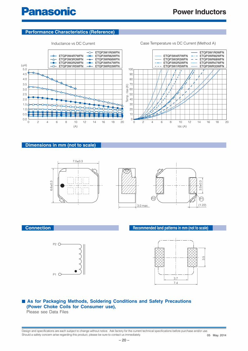
● Small type (8.7×7.0×H3.0 mm)● High power (22 A)● Low loss (RDC :1.12 mΩ)● Tighter DCR tolerance (±7 %)● Suitable for high frequency circuit (up to 1 MHz)● Low buzz noise due to its gap-less structure● RoHS compliant
● Notebook PC power supply modules● Servers, Routers, DC/DC converters for driving CPUs
● 3,000 pcs./box (2 reel)
Power Choke Coil
Series : PCC-M0730L (MC)
Small mounting size for multi-phase DC/DC converter circuits
Standard Parts
Standard Packing Quantity (Minimum Quantity/Packing Unit)
(✽1) Inductance is measured at 1.0 MHz.(✽2) Rated current defines actual value of DC current, when temperature rise of coil becomes 40 K. (Method A)(✽3) Rated current defines actual value of DC current, when temperature rise of coil becomes 40 K. (Method B)(✽4) Reference only(✽5) Method A (PANASONIC's standard measurement conditions), Method B (high heat dissipation measurement) is different from Method A by the measurement methods. In normal application condition, the part's temperature depends on circuit design and heat dissipation condition. This condition shall be verified by the worst operational condition.
Part No.
Inductance (at 20 °C)✽1
Rated current
(A)✽2
Rated current
(ref)
(A)✽3
DC resistance
(at 20 °C)
(mΩ)
L0 at 0A L1 ✽4
(μH) (μH)
Measurement
current
(A)
ETQP3LR24CFM 0.24±20 % (0.19) 22 22 35 1.12±7 %
May. 201502

Design and specifications are each subject to change without notice. Ask factory for the current technical specifications before purchase and/or use.
Should a safety concern arise regarding this product, please be sure to contact us immediately.
Power Inductors
– 22 –
P2
P1
8.7 max.
3.0 max.
0.01 min.
7.0
±0.3
2.0
2.0
±0.3
P1 P2
2.8 3.6 2.8
2.6
0.00
0.05
0.10
0.15
0.20
0.30
0.25
0.35
0.40
0.45
0 5 10 15 20 25 30
(A)
(uH) ETQP3LR24CFM
0
10
20
30
40
50
60
70
80
90
100
0 5 10 2015 25 30
Idc (A)
Te
mp
. rise
(K
)
ETQP3LR24CFM
Connection
■ As for Packaging Methods, Soldering Conditions and Safety Precautions (Power Choke Coils for Consumer use), Please see Data Files
Recommended land patterns in mm (not to scale)
Performance Characteristics (Reference)
Dimensions in mm (not to scale)
Inductance vs DC Current Case Temperature vs DC Current (Method A)
May. 201502
Design and specifications are each subject to change without notice. Ask factory for the current technical specifications before purchase and/or use.
Should a safety concern arise regarding this product, please be sure to contact us immediately.
Power Inductors
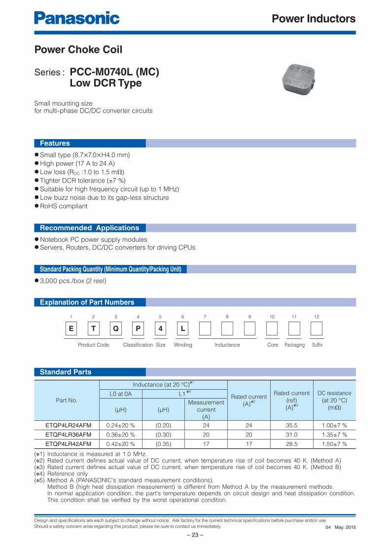
– 23 –
E
1 2
Q
3
P 4 L
4 5 6 7 8 9
Product Code InductanceClassification
10 11 12
SuffixPackagingCoreWindingSize
T
Explanation of Part Numbers
Features
Recommended Applications
● Small type (8.7×7.0×H4.0 mm)● High power (17 A to 24 A)● Low loss (RDC :1.0 to 1.5 mΩ)● Tighter DCR tolerance (±7 %)● Suitable for high frequency circuit (up to 1 MHz)● Low buzz noise due to its gap-less structure● RoHS compliant
● Notebook PC power supply modules● Servers, Routers, DC/DC converters for driving CPUs
● 3,000 pcs./box (2 reel)
Power Choke Coil
Series : PCC-M0740L (MC) Low DCR Type
Small mounting size for multi-phase DC/DC converter circuits
Standard Parts
Standard Packing Quantity (Minimum Quantity/Packing Unit)
(✽1) Inductance is measured at 1.0 MHz.(✽2) Rated current defines actual value of DC current, when temperature rise of coil becomes 40 K. (Method A)(✽3) Rated current defines actual value of DC current, when temperature rise of coil becomes 40 K. (Method B)(✽4) Reference only(✽5) Method A (PANASONIC's standard measurement conditions), Method B (high heat dissipation measurement) is different from Method A by the measurement methods. In normal application condition, the part's temperature depends on circuit design and heat dissipation condition. This condition shall be verified by the worst operational condition.
Part No.
Inductance (at 20 °C)✽1
Rated current
(A)✽2
Rated current
(ref)
(A)✽3
DC resistance
(at 20 °C)
(mΩ)
L0 at 0A L1 ✽4
(μH) (μH)
Measurement
current
(A)
ETQP4LR24AFM 0.24±20 % (0.20) 24 24 35.5 1.00±7 %
ETQP4LR36AFM 0.36±20 % (0.30) 20 20 31.0 1.35±7 %
ETQP4LR42AFM 0.42±20 % (0.35) 17 17 28.5 1.50±7 %
May. 201504
Design and specifications are each subject to change without notice. Ask factory for the current technical specifications before purchase and/or use.
Should a safety concern arise regarding this product, please be sure to contact us immediately.
Power Inductors
– 24 –
P2
P1
8.7 max.
4.0 max.
0.01 min.
7.0
±0.3
2.0
A
P1 P2
2.8 3.6 2.8
B
0.00
0.05
0.10
0.15
0.20
0.30
0.25
0.35
0.40
0.45
0 5 10 15 20 25 30
(A)
(uH)ETQP4LR36AFMETQP4LR24AFM
0
10
20
30
40
50
60
70
80
90
100
0 5 10 2015 25 30
Idc (A)
Tem
p. rise
(K
)
ETQP4LR42AFMETQP4LR36AFMETQP4LR24AFM
ETQP4LR42AFM
Connection
■ As for Packaging Methods, Soldering Conditions and Safety Precautions (Power Choke Coils for Consumer use), Please see Data Files
Recommended land patterns in mm (not to scale)
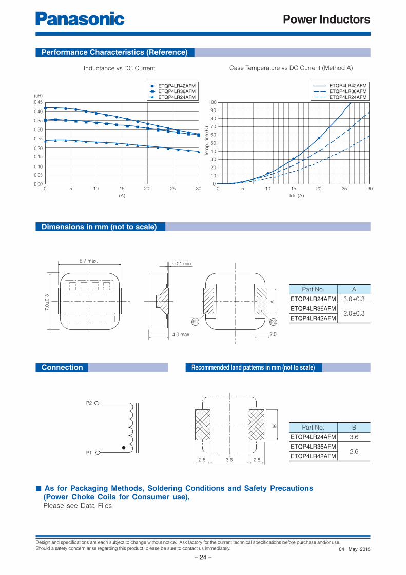
Performance Characteristics (Reference)
Dimensions in mm (not to scale)
Inductance vs DC Current Case Temperature vs DC Current (Method A)
Part No. A
ETQP4LR24AFM 3.0±0.3
ETQP4LR36AFM2.0±0.3
ETQP4LR42AFM
Part No. B
ETQP4LR24AFM 3.6
ETQP4LR36AFM2.6
ETQP4LR42AFM
May. 201504
Design and specifications are each subject to change without notice. Ask factory for the current technical specifications before purchase and/or use.
Should a safety concern arise regarding this product, please be sure to contact us immediately.
Power Inductors
– 25 –
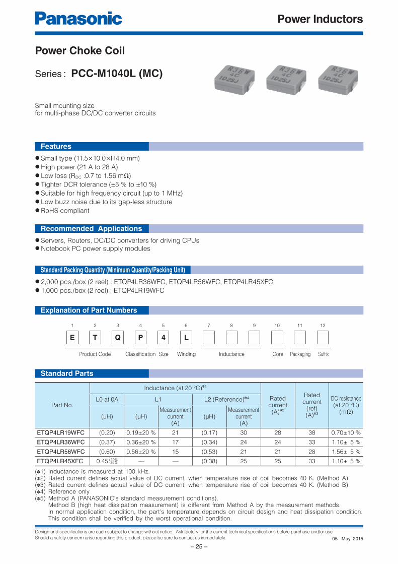
E
1 2
Q
3
P 4 L
4 5 6 7 8 9
Product Code InductanceClassification
10 11 12
SuffixPackagingCoreWindingSize
T
Explanation of Part Numbers
Features
Recommended Applications
● Small type (11.5×10.0×H4.0 mm)● High power (21 A to 28 A)● Low loss (RDC :0.7 to 1.56 mΩ)● Tighter DCR tolerance (±5 % to ±10 %)● Suitable for high frequency circuit (up to 1 MHz)● Low buzz noise due to its gap-less structure● RoHS compliant
● Servers, Routers, DC/DC converters for driving CPUs● Notebook PC power supply modules
● 2,000 pcs./box (2 reel) : ETQP4LR36WFC, ETQP4LR56WFC, ETQP4LR45XFC● 1,000 pcs./box (2 reel) : ETQP4LR19WFC
Power Choke Coil
Series : PCC-M1040L (MC)
Small mounting size for multi-phase DC/DC converter circuits
Standard Parts
Standard Packing Quantity (Minimum Quantity/Packing Unit)
(✽1) Inductance is measured at 100 kHz.(✽2) Rated current defines actual value of DC current, when temperature rise of coil becomes 40 K. (Method A)(✽3) Rated current defines actual value of DC current, when temperature rise of coil becomes 40 K. (Method B)(✽4) Reference only(✽5) Method A (PANASONIC's standard measurement conditions), Method B (high heat dissipation measurement) is different from Method A by the measurement methods. In normal application condition, the part's temperature depends on circuit design and heat dissipation condition. This condition shall be verified by the worst operational condition.
Part No.
Inductance (at 20 °C)✽1
Rated current(A)✽2
Rated current
(ref)(A)✽3
DC resistance(at 20 °C)
(mΩ)
L0 at 0A L1 L2 (Reference)✽4
(µH) (µH)Measurement
current(A)
(µH)Measurement
current(A)
ETQP4LR19WFC (0.20) 0.19±20 % 21 (0.17) 30 28 38 0.70±10 %
ETQP4LR36WFC (0.37) 0.36±20 % 17 (0.34) 24 24 33 1.10± 5 %
ETQP4LR56WFC (0.60) 0.56±20 % 15 (0.53) 21 21 28 1.56± 5 %
ETQP4LR45XFC 0.45+20% — — (0.38) 25 25 33 1.10± 5 %–25%
May. 201505
Design and specifications are each subject to change without notice. Ask factory for the current technical specifications before purchase and/or use.
Should a safety concern arise regarding this product, please be sure to contact us immediately.
Power Inductors
– 26 –
P2
P1
11.5 max.
4.0 max.
0.01 min.
10.0
±0.3
2.5
4.0
±0.2
P1 P2
0.0
0.1
0.2
0.3
0.4
0.5
0.6
0.7
0.8
0 2 4 6 8 10 12 14 16 18 20 22 24 26 28 30
(A)
(uH)
ETQP4LR56WFCETQP4LR36WFCETQP4LR19WFCETQP4LR45XFC
0
10
20
30
40
50
60
70
80
90
100
0 5 10 15 20 25 30
Idc (A)
Tem
p. rise
(K
)
ETQP4LR56WFC
ETQP4LR36WFC / ETQP4LR45XFC
ETQP4LR19WFC
3.8 6.0 3.8
4.6
Connection
■ As for Packaging Methods, Soldering Conditions and Safety Precautions (Power Choke Coils for Consumer use), Please see Data Files
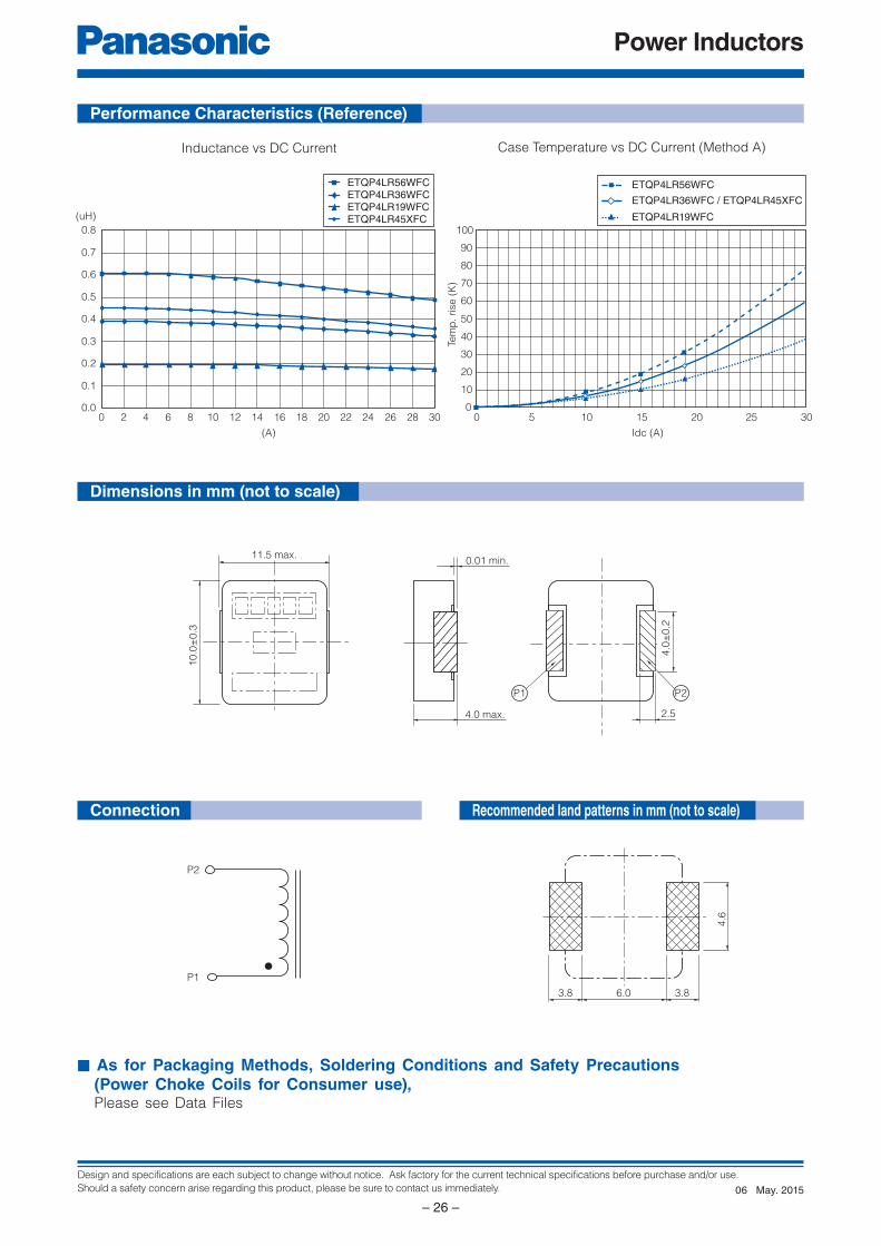
Performance Characteristics (Reference)
Dimensions in mm (not to scale)
Inductance vs DC Current Case Temperature vs DC Current (Method A)
Recommended land patterns in mm (not to scale)
May. 201506
Design and specifications are each subject to change without notice. Ask factory for the current technical specifications before purchase and/or use.
Should a safety concern arise regarding this product, please be sure to contact us immediately.
Power Inductors
– 27 –
E
1 2
Q
3
P 4 L
4 5 6 7 8 9
Product Code InductanceClassification
10 11 12
SuffixPackagingCoreWindingSize
T
Explanation of Part Numbers
Features
Recommended Applications
● Small type (11.7×10.0×H4.0 mm)● High power (21 A to 30 A)● Low loss (RDC :0.76 to 1.58 mΩ)● Tighter DCR tolerance (±5 %)● Suitable for high frequency circuit (up to 1 MHz)● Low buzz noise due to its gap-less structure● RoHS compliant
● Notebook PC power supply modules● Servers, Routers, DC/DC converters for driving CPUs
● 2,000 pcs./box (2 reel)
Power Choke Coil
Series : PCC-M1040L (MC) Low DCR Type
Small mounting size for multi-phase DC/DC converter circuits
Standard Parts
Standard Packing Quantity (Minimum Quantity/Packing Unit)
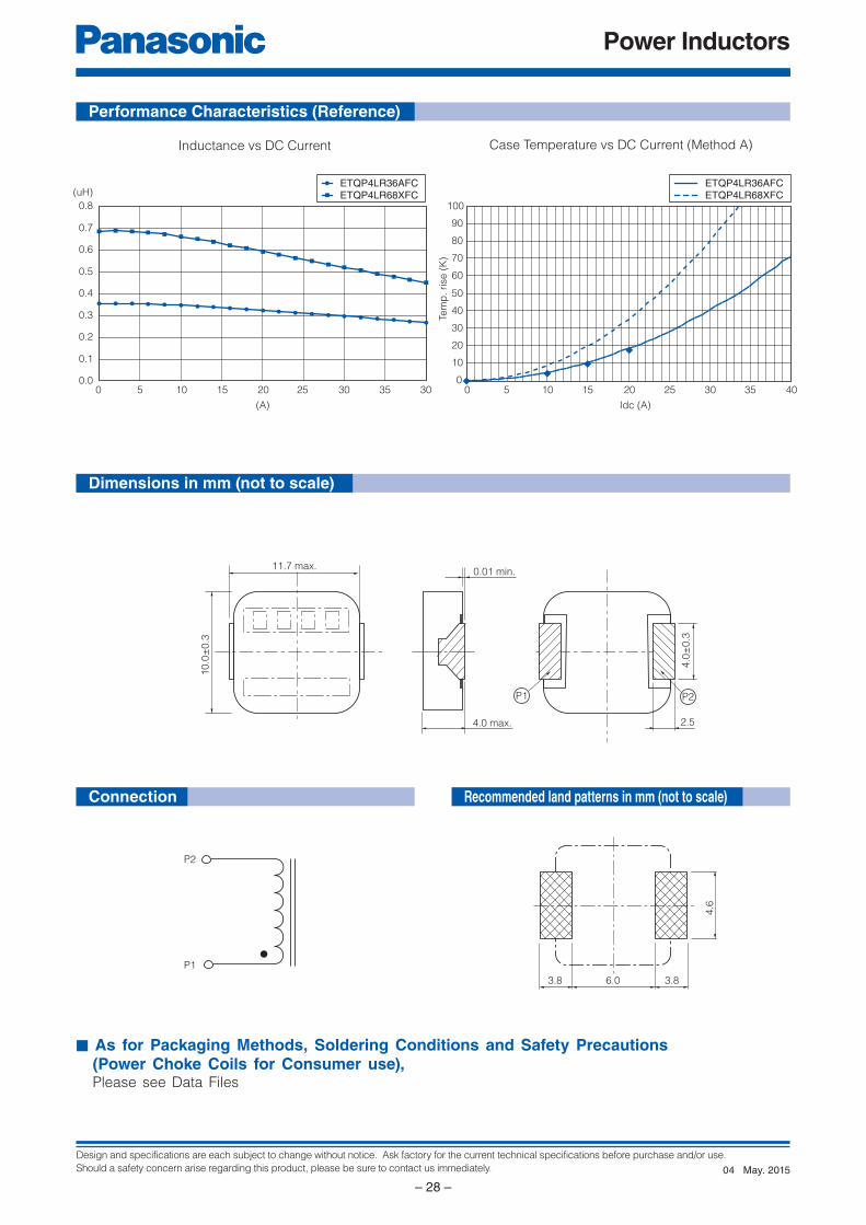
(✽1) Inductance is measured at 1.0 MHz.(✽2) Rated current defines actual value of DC current, when temperature rise of coil becomes 40 K. (Method A)(✽3) Rated current defines actual value of DC current, when temperature rise of coil becomes 40 K. (Method B)(✽4) Reference only(✽5) Method A (PANASONIC's standard measurement conditions), Method B (high heat dissipation measurement) is different from Method A by the measurement methods. In normal application condition, the part's temperature depends on circuit design and heat dissipation condition. This condition shall be verified by the worst operational condition.
Part No.
Inductance (at 20 °C)✽1
Rated current
(A)✽2
Rated current
(ref)
(A)✽3
DC resistance
(at 20 °C)
(mΩ)
L0 at 0A L1 ✽4
(μH) (μH)
Measurement
current
(A)
ETQP4LR36AFC 0.36±20 % (0.29) 30 30 40 0.76±5 %
ETQP4LR68XFC 0.68±20 % (0.59) 21 21 28 1.58±5 %
May. 201504
Design and specifications are each subject to change without notice. Ask factory for the current technical specifications before purchase and/or use.
Should a safety concern arise regarding this product, please be sure to contact us immediately.
Power Inductors
– 28 –
P2
P1
11.7 max.
4.0 max.
0.01 min.
10.0
±0.3
2.5
4.0
±0.3
P1 P2
3.8 6.0 3.8
4.6
0.0
0.1
0.2
0.3
0.4
0.5
0.6
0.7
0.8
0 5 10 15 20 25 30 35 30
(A)
(uH)ETQP4LR36AFCETQP4LR68XFC
0
10
20
30
40
50
60
70
80
90
100
0 5 10 2015 25 30 35 40
Idc (A)
Tem
p. rise
(K
)
ETQP4LR36AFCETQP4LR68XFC
Connection
■ As for Packaging Methods, Soldering Conditions and Safety Precautions (Power Choke Coils for Consumer use), Please see Data Files
Performance Characteristics (Reference)
Dimensions in mm (not to scale)
Recommended land patterns in mm (not to scale)
Inductance vs DC Current Case Temperature vs DC Current (Method A)
May. 201504
Design and specifications are each subject to change without notice. Ask factory for the current technical specifications before purchase and/or use.
Should a safety concern arise regarding this product, please be sure to contact us immediately.
Power Inductors
– 29 –
E
1 2
Q
3
P 4 W
4 5 6 7 8 9
Product Code InductanceClassification
10 11 12
SuffixPackagingCoreWindingSize
T
Explanation of Part Numbers
Features
Recommended Applications
● Small type (11.0×10.0×H4.0 mm)● High power (13 A)● Low loss (RDC : 4.0 mΩ)● Suitable for high frequency circuit (up to 1 MHz)● Low buzz noise due to its gap-less structure● RoHS compliant
● Notebook PC power supply modules● Servers, Routers, DC/DC converters for driving CPUs
● 1,000 pcs./box (2 reel)
Power Choke Coil
Series : PCC-M1040W (MC)
High power, Low loss, Low-profi le
Standard Parts
Standard Packing Quantity (Minimum Quantity/Packing Unit)
(✽1) Inductance is measured at 100 kHz.(✽2) Rated current defines actual value of DC current, when temperature rise of coil becomes 40 K. (Method A)(✽3) Reference only(✽4) Method A (PANASONIC's standard measurement conditions)
Part No.
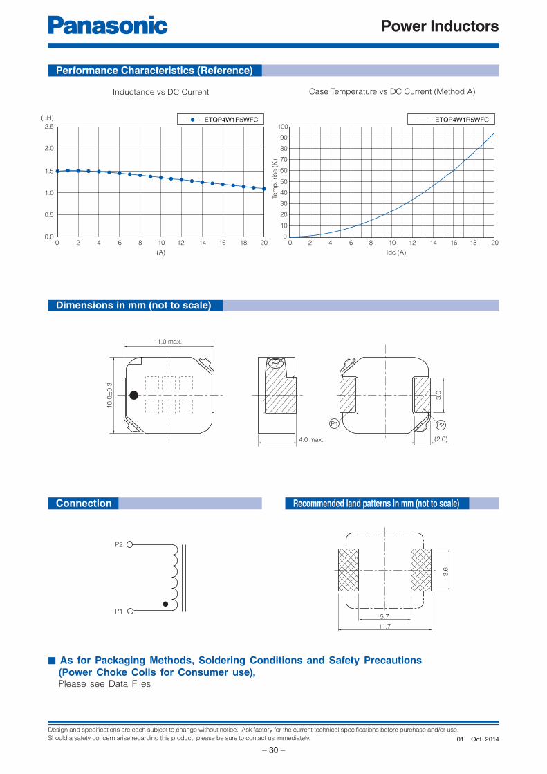
Inductance (at 20 °C)✽1
Rated current(A)✽2
DC resistance(at 20 °C)(mΩ) max.
L0 at 0A L1✽3
(μH) (μH)Measurement
current(A)
ETQP4W1R5WFC 1.5±20 % (1.27) 13 13 4.0±15 %
Industrial Property : patents 10 (Registered 8 / Pending 2)
Oct. 201401
Design and specifications are each subject to change without notice. Ask factory for the current technical specifications before purchase and/or use.
Should a safety concern arise regarding this product, please be sure to contact us immediately.
Power Inductors
– 30 –
P2
P1
11.0 max.
4.0 max.
10.0
±0.3
(2.0)3.0
P1 P2
5.7
11.7
3.6
0.0
0.5
1.0
1.5
2.0
2.5
0 2 4 6 108 12 14 16 2018
(A)
(uH)
0
10
20
30
40
50
60
70
80
90
100
0 2 864 10 12 14 16 18 20
Idc (A)
Tem
p. rise
(K
)
ETQP4W1R5WFC ETQP4W1R5WFC
Connection
■ As for Packaging Methods, Soldering Conditions and Safety Precautions (Power Choke Coils for Consumer use), Please see Data Files
Performance Characteristics (Reference)
Dimensions in mm (not to scale)
Recommended land patterns in mm (not to scale)
Inductance vs DC Current Case Temperature vs DC Current (Method A)
Oct. 201401
Design and specifications are each subject to change without notice. Ask factory for the current technical specifications before purchase and/or use.
Should a safety concern arise regarding this product, please be sure to contact us immediately.
Power Inductors
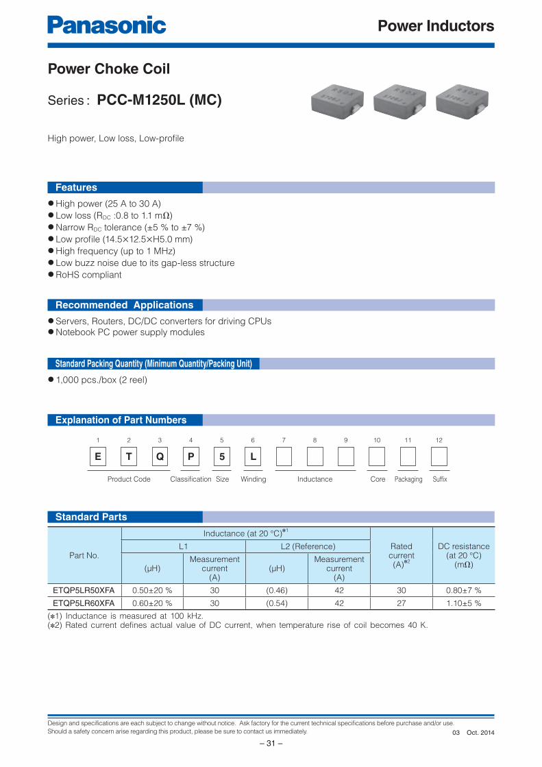
– 31 –
E
1 2
Q
3
P 5 L
4 5 6 7 8 9
Product Code InductanceClassification
10 11 12
SuffixPackagingCoreWindingSize
T
Explanation of Part Numbers
Features
Recommended Applications
● High power (25 A to 30 A)● Low loss (RDC :0.8 to 1.1 mΩ)● Narrow RDC tolerance (±5 % to ±7 %)● Low profi le (14.5×12.5×H5.0 mm)● High frequency (up to 1 MHz)● Low buzz noise due to its gap-less structure● RoHS compliant
● Servers, Routers, DC/DC converters for driving CPUs● Notebook PC power supply modules
● 1,000 pcs./box (2 reel)
Power Choke Coil
Series : PCC-M1250L (MC)
High power, Low loss, Low-profi le
Standard Parts
Standard Packing Quantity (Minimum Quantity/Packing Unit)
Part No.
Inductance (at 20 °C)✽1
Rated current(A)
✽2
DC resistance(at 20 °C)
(mΩ)
L1 L2 (Reference)
(µH)Measurement
current(A)
(µH)Measurement
current(A)
ETQP5LR50XFA 0.50±20 % 30 (0.46) 42 30 0.80±7 %
ETQP5LR60XFA 0.60±20 % 30 (0.54) 42 27 1.10±5 %
(✽1) Inductance is measured at 100 kHz.(✽2) Rated current defines actual value of DC current, when temperature rise of coil becomes 40 K.
Oct. 201403
Design and specifications are each subject to change without notice. Ask factory for the current technical specifications before purchase and/or use.
Should a safety concern arise regarding this product, please be sure to contact us immediately.
Power Inductors
– 32 –
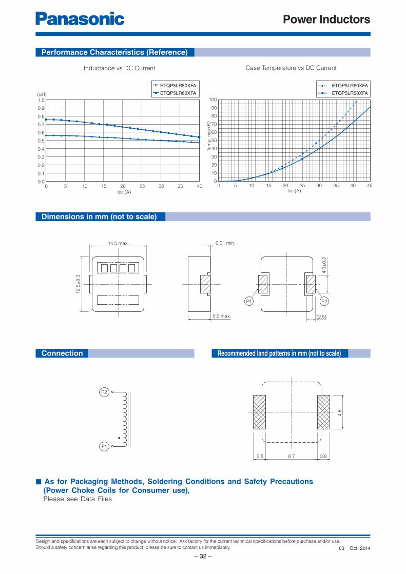
ETQP5LR50XFA
ETQP5LR60XFA
0.0
0.1
0.2
0.3
0.4
0.5
0.6
0.7
0.8
0.9
1.0
0 5 10 15 20 25 30 35 40
IDC (A)
(uH)
ETQP5LR60XFA
ETQP5LR50XFA
0
10
20
30
40
50
60
70
80
90
100
0 5 10 15 20 25 30 35 40 45IDC (A)
Tem
p. rise
(K
)
P2P1
14.5 max.
5.0 max. (2.5)
0.01 min.
12.5
±0.3
4.0
±0.2
3.8
4.6
8.73.8
P2
P1
Connection
■ As for Packaging Methods, Soldering Conditions and Safety Precautions (Power Choke Coils for Consumer use), Please see Data Files
Performance Characteristics (Reference)
Dimensions in mm (not to scale)
Recommended land patterns in mm (not to scale)
Inductance vs DC Current Case Temperature vs DC Current
Oct. 201403
Design and specifications are each subject to change without notice. Ask factory for the current technical specifications before purchase and/or use.
Should a safety concern arise regarding this product, please be sure to contact us immediately.
Power Inductors
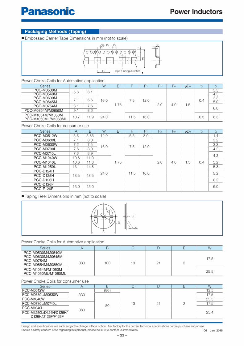
– 33 –
t1t2P0
A
P2fD0
P1
FE
W
B
Tape running direction
EC
D
A
B
W
Power Choke Coils for Automotive application
Series A B W E F P1 P2 P0 fD0 t1 t2PCC-M0530M
5.6 6.1
16.01.75
7.5 12.02.0 4.0 1.5
0.4
3.3PCC-M0540M 4.3PCC-M0630M
7.1 6.63.3
PCC-M0645M 5.0PCC-M0754M 8.1 7.6
6.0PCC-M0854M/M0850M 9.1 8.6
PCC-M1054M/M1050MPCC-M1050ML/M1060ML
10.7 11.9 24.0 11.5 16.0 0.5 6.3
Power Choke Coils for consumer use
Series A B W E F P1 P2 P0 fD0 t1 t2
PCC-M0512W 5.6 5.85 12.0
1.75
5.5 8.0
2.0 4.0 1.5 0.4
1.4PCC-M0630L 7.1 8.0
16.0 7.5 12.0
3.2PCC-M0630W 7.2 7.5 3.3PCC-M0730L 7.6 8.9 4.2PCC-M0740L 7.6 8.9
4.3PCC-M1040W 10.6 11.0
24.0 11.5 16.0
PCC-M1040L 10.6 11.8 5.2PCC-M1250L 13.1 14.8 5.3PCC-D124H
13.5 13.55.2
PCC-D125HPCC-D126H 6.2PCC-D126F
13.0 13.0 6.0PCC-F126F
Power Choke Coils for Automotive application
Series A B C D E W
PCC-M0530M/M0540MPCC-M0630M/M0645MPCC-M0754MPCC-M0854M/M0850M 330 100 13 21 2
17.5
PCC-M1054M/M1050MPCC-M1050ML/M1060ML
25.5
Power Choke Coils for consumer use
Series A B C D E WPCC-M0512W
330(80)
13 21 2
13.5PCC-M0630L/M0630W
80
17.5PCC-M1040W 25.5PCC-M0730L/M0740L
380
17.5PCC-M1040L
25.4PCC- M1250L/D124H/D125H/D126H/D126F/F126F
● Taping Reel Dimensions in mm (not to scale)
● Embossed Carrier Tape Dimensions in mm (not to scale)
Packaging Methods (Taping)
Jan. 201506
Design and specifications are each subject to change without notice. Ask factory for the current technical specifications before purchase and/or use.
Should a safety concern arise regarding this product, please be sure to contact us immediately.
Power Inductors
– 34 –
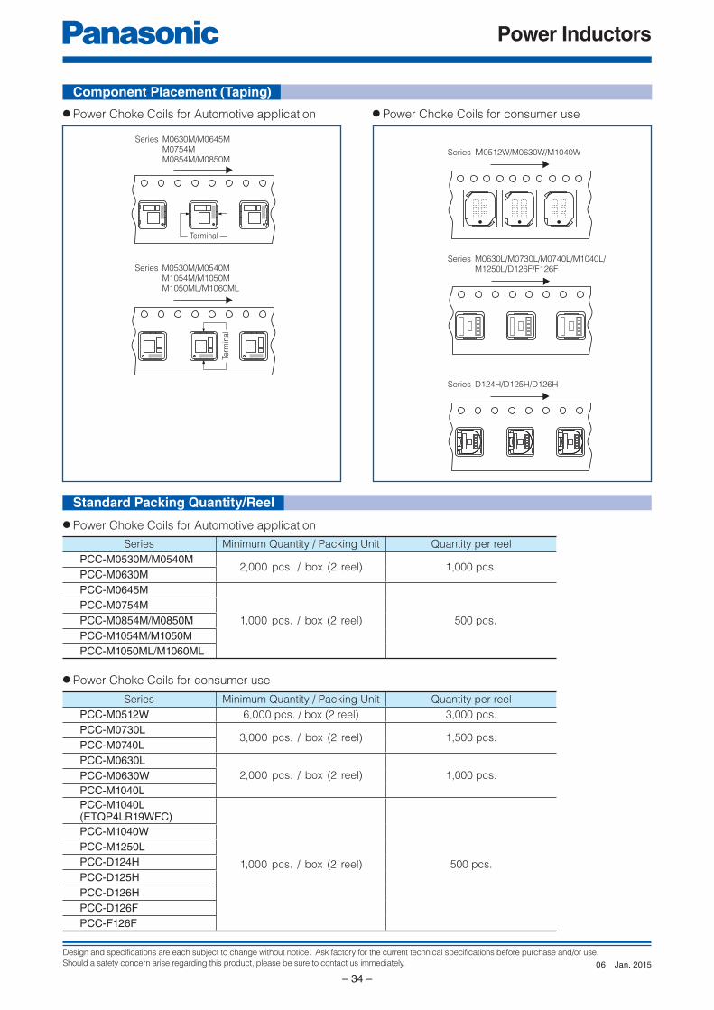
Term
inal
Terminal
Series M0530M/M0540M
M1054M/M1050M
M1050ML/M1060ML
Series M0630M/M0645M
M0754M
M0854M/M0850M
Series M0630L/M0730L/M0740L/M1040L/
M1250L/D126F/F126F
Series D124H/D125H/D126H
Series M0512W/M0630W/M1040W
Component Placement (Taping)
● Power Choke Coils for Automotive application ● Power Choke Coils for consumer use
● Power Choke Coils for Automotive application
● Power Choke Coils for consumer use
Series Minimum Quantity / Packing Unit Quantity per reel
PCC-M0530M/M0540M2,000 pcs. / box (2 reel) 1,000 pcs.
PCC-M0630M
PCC-M0645M
1,000 pcs. / box (2 reel) 500 pcs.
PCC-M0754M
PCC-M0854M/M0850M
PCC-M1054M/M1050M
PCC-M1050ML/M1060ML
Series Minimum Quantity / Packing Unit Quantity per reel
PCC-M0512W 6,000 pcs. / box (2 reel) 3,000 pcs.
PCC-M0730L3,000 pcs. / box (2 reel) 1,500 pcs.
PCC-M0740L
PCC-M0630L
2,000 pcs. / box (2 reel) 1,000 pcs.PCC-M0630W
PCC-M1040L
PCC-M1040L(ETQP4LR19WFC)
1,000 pcs. / box (2 reel) 500 pcs.
PCC-M1040W
PCC-M1250L
PCC-D124H
PCC-D125H
PCC-D126H
PCC-D126F
PCC-F126F
Standard Packing Quantity/Reel
Jan. 201506
Design and specifications are each subject to change without notice. Ask factory for the current technical specifications before purchase and/or use.
Should a safety concern arise regarding this product, please be sure to contact us immediately.
Power Inductors
– 35 –
t2
Tem
pe
ratu
re (
°C)
Time
T3
T2
T1
t1
0
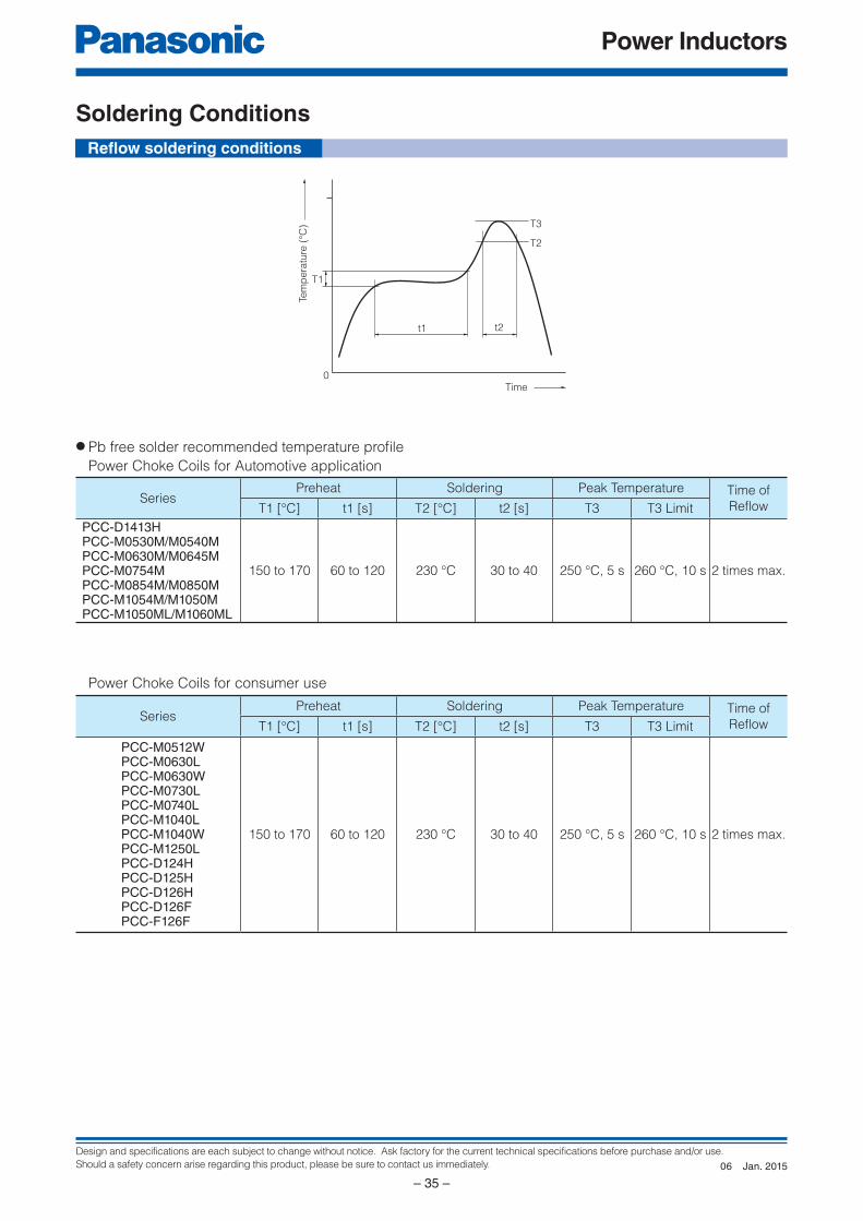
Soldering Conditions
SeriesPreheat Soldering Peak Temperature Time of
Refl owT1 [°C] t1 [s] T2 [°C] t2 [s] T3 T3 Limit
PCC-D1413HPCC-M0530M/M0540MPCC-M0630M/M0645MPCC-M0754MPCC-M0854M/M0850MPCC-M1054M/M1050MPCC-M1050ML/M1060ML
150 to 170 60 to 120 230 °C 30 to 40 250 °C, 5 s 260 °C, 10 s 2 times max.
SeriesPreheat Soldering Peak Temperature Time of
Refl owT1 [°C] t1 [s] T2 [°C] t2 [s] T3 T3 Limit
PCC-M0512WPCC-M0630LPCC-M0630WPCC-M0730LPCC-M0740LPCC-M1040LPCC-M1040WPCC-M1250LPCC-D124HPCC-D125HPCC-D126HPCC-D126FPCC-F126F
150 to 170 60 to 120 230 °C 30 to 40 250 °C, 5 s 260 °C, 10 s 2 times max.
● Pb free solder recommended temperature profi le
Power Choke Coils for Automotive application
Power Choke Coils for consumer use
Refl ow soldering conditions
Jan. 201506
Design and specifications are each subject to change without notice. Ask factory for the current technical specifications before purchase and/or use.
Should a safety concern arise regarding this product, please be sure to contact us immediately.
Power Inductors
– 36 –
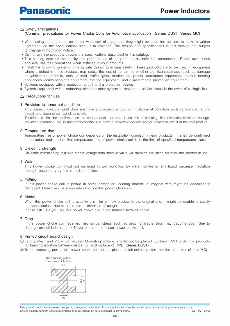
8.4
The opposing part in
the choke coil bottom
3.6 8
2.8
10
Precautions for use
1. Provision to abnormal conditionThis power choke coil itself does not have any protective function in abnormal condition such as overload, short-
circuit and open-circuit conditions, etc.
Therefore, it shall be confirmed as the end product that there is no risk of smoking, fire, dielectric withstand voltage,
insulation resistance, etc. in abnormal conditions to provide protective devices and/or protection circuit in the end product.
2. Temperature riseTemperature rise of power choke coil depends on the installation condition in end products. It shall be confirmed
in the actual end product that temperature rise of power choke coil is in the limit of specified temperature class.
3. Dielectric strengthDielectric withstanding test with higher voltage than specific value will damage Insulating material and shorten its life.
4. WaterThis Power choke coil must not be used in wet condition by water, coffee or any liquid because insulation
strength becomes very low in such condition.
5. PottingIf this power choke coil is potted in some compound, coating material of magnet wire might be occasionally
damaged. Please ask us if you intend to pot this power choke coil.
6. ModelWhen this power choke coil is used in a similar or new product to the original one, it might be unable to satisfy
the specifications due to difference of condition of usage.
Please ask us if you use this power choke coil in the manner such as above.
7. DropIf the power choke coil receives mechanical stress such as drop, characteristics may become poor (due to
damage on coil bobbin, etc.). Never use such stressed power choke coil.
8. Printed circuit board design
1 Land pattern and Via which exceed Operating Voltage, should not be placed top layer PWB under the products for keeping isolation between inside coil and surface of PWB. (Series DUST)
2 To the opposing part in this power choke coil bottom please install neither pattern nor the beer, etc. (Series MC)
Safety Precautions (Common precautions for Power Choke Coils for Automotive application : Series DUST, Series MC)
• When using our products, no matter what sort of equipment they might be used for, be sure to make a written
agreement on the specifications with us in advance. The design and specifications in this catalog are subject
to change without prior notice.
• Do not use the products beyond the specifications described in this catalog.
• This catalog explains the quality and performance of the products as individual components. Be fore use, check
and evaluate their operations when installed in your products.
• Install the following systems for a failsafe design to ensure safety if these products are to be used in equip ment
where a defect in these products may cause the loss of human life or other significant damage, such as damage
to vehicles (au to mo bile, train, vessel), traffic lights, medical equipment, aerospace equipment, elec tric heating
ap pli anc es, com bus tion/gas equipment, rotating equipment, and disaster/crime prevention equip ment.
✽ Systems equipped with a protection circuit and a protection device
✽ Systems equipped with a redundant circuit or other system to prevent an unsafe status in the event of a single fault
Oct. 201401
Design and specifications are each subject to change without notice. Ask factory for the current technical specifications before purchase and/or use.
Should a safety concern arise regarding this product, please be sure to contact us immediately.
Power Inductors
– 37 –
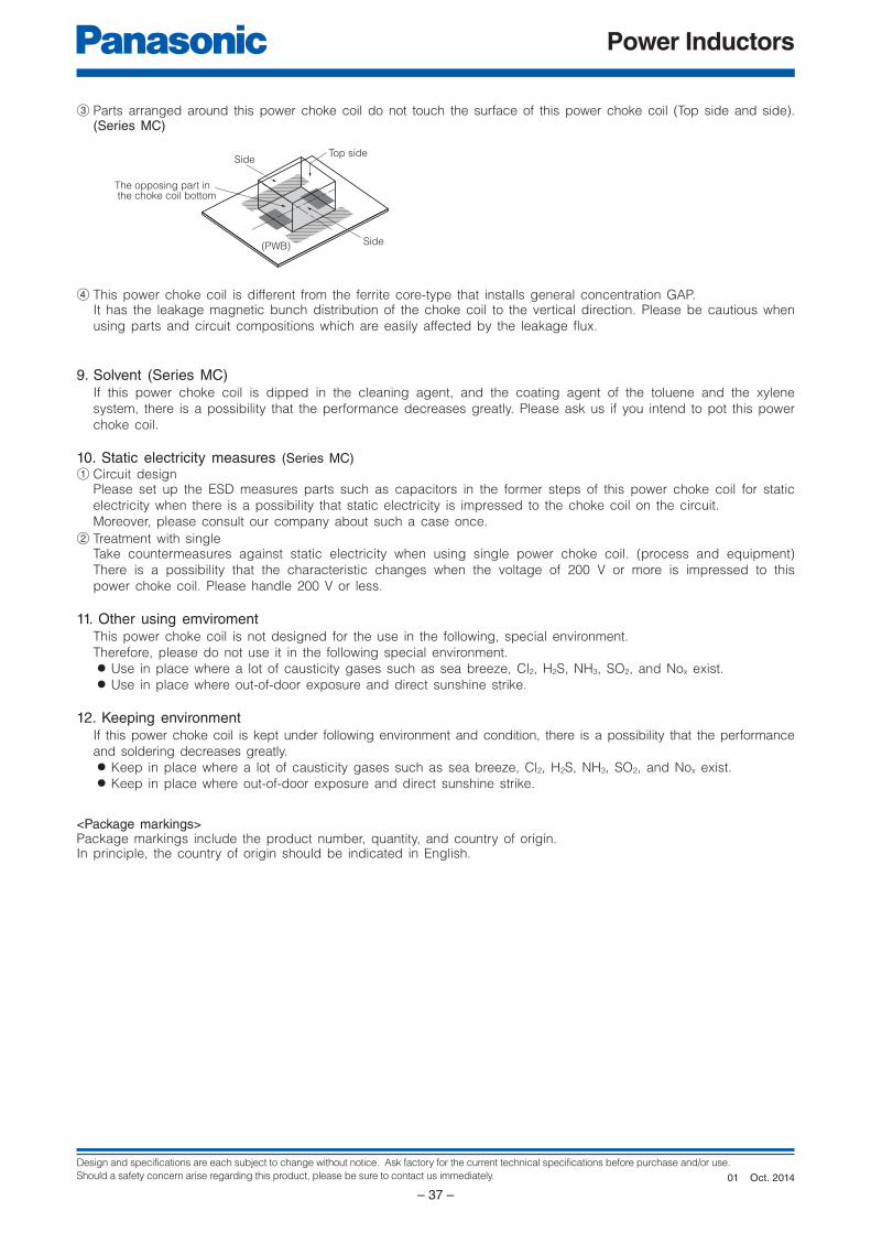
Top sideSide
Side (PWB)
The opposing part in the choke coil bottom
<Package markings>Package markings include the product number, quantity, and country of origin.In principle, the country of origin should be indicated in English.
3 Parts arranged around this power choke coil do not touch the surface of this power choke coil (Top side and side). (Series MC)
4 This power choke coil is different from the ferrite core-type that installs general concentration GAP. It has the leakage magnetic bunch distribution of the choke coil to the vertical direction. Please be cautious when
using parts and circuit compositions which are easily affected by the leakage flux.
9. Solvent (Series MC)If this power choke coil is dipped in the cleaning agent, and the coating agent of the toluene and the xylene
system, there is a possibility that the performance decreases greatly. Please ask us if you intend to pot this power
choke coil.
10. Static electricity measures (Series MC)
1 Circuit designPlease set up the ESD measures parts such as capacitors in the former steps of this power choke coil for static
electricity when there is a possibility that static electricity is impressed to the choke coil on the circuit.
Moreover, please consult our company about such a case once.
2 Treatment with singleTake countermeasures against static electricity when using single power choke coil. (process and equipment)
There is a possibility that the characteristic changes when the voltage of 200 V or more is impressed to this
power choke coil. Please handle 200 V or less.
11. Other using emviromentThis power choke coil is not designed for the use in the following, special environment.
Therefore, please do not use it in the following special environment. ● Use in place where a lot of causticity gases such as sea breeze, Cl2, H2S, NH3, SO2, and Nox exist. ● Use in place where out-of-door exposure and direct sunshine strike.
12. Keeping environmentIf this power choke coil is kept under following environment and condition, there is a possibility that the performance
and soldering decreases greatly. ● Keep in place where a lot of causticity gases such as sea breeze, Cl2, H2S, NH3, SO2, and Nox exist. ● Keep in place where out-of-door exposure and direct sunshine strike.
Oct. 201401

Design and specifications are each subject to change without notice. Ask factory for the current technical specifications before purchase and/or use.
Should a safety concern arise regarding this product, please be sure to contact us immediately.
Power Inductors
– 38 –
Precautions for use
1. Provision to abnormal conditionThis power choke coil itself does not have any protective function in abnormal condition such as overload, short-circuit and open-circuit conditions, etc.Therefore, it shall be confirmed as the end product that there is no risk of smoking, fire, dielectric withstand voltage, insulation resistance, etc. in abnormal conditions to provide protective devices and/or protection circuit in the end product.
2. Temperature riseTemperature rise of power choke coil depends on the installation condition in end products. It shall be confirmed in the actual end product that temperature rise of power choke coil is in the limit of specified temperature class.
3. Dielectric strengthDielectric withstanding test with higher voltage than specific value will damage Insulating material and shorten its life.
4. WaterThis Power choke coil must not be used in wet condition by water, coffee or any liquid because insulation strength becomes very low in such condition.
5. PottingIf this power choke coil is potted in some compound, coating material of magnet wire might be occasionally damaged. Please ask us if you intend to pot this power choke coil.
6. DetergentPlease consult our company when using detergent for the power choke coil as reliability confirmation etc., is necessary.
7. Storage temperature-5 °C to +35 °C
8. Operating temperatureMinimum temperature : -40 °C (Ambient temperature of the power choke coil)Maximum temperature : 130 °C (Ambient temperature of the power choke coil plus the temperature rise) 100 °C (Only series : PCC-F126F(N6))
9. ModelWhen this power choke coil is used in a similar or new product to the original one, it might be unable to satisfy the specifications due to difference of condition of usage.Please ask us if you use this power choke coil in the manner such as above.
10. DropIf the power choke coil receives mechanical stress such as drop, characteristics may become poor (due to damage on coil bobbin, etc.). Never use such stressed power choke coil.
Safety Precautions (Common precautions for Power Choke Coils for consumer use)
• When using our products, no matter what sort of equipment they might be used for, be sure to make a written
agreement on the specifications with us in advance. The design and specifications in this catalog are subject
to change without prior notice.
• Do not use the products beyond the specifications described in this catalog.
• This catalog explains the quality and performance of the products as individual components. Be fore use, check
and evaluate their operations when installed in your products.
• Install the following systems for a failsafe design to ensure safety if these products are to be used in equip ment
where a defect in these products may cause the loss of human life or other significant damage, such as damage
to vehicles (au to mo bile, train, vessel), traffic lights, medical equipment, aerospace equipment, elec tric heating
ap pli anc es, com bus tion/gas equipment, rotating equipment, and disaster/crime prevention equip ment.
✽ Systems equipped with a protection circuit and a protection device
✽ Systems equipped with a redundant circuit or other system to prevent an unsafe status in the event of a single fault
<Package markings>Package markings include the product number, quantity, and country of origin.In principle, the country of origin should be indicated in English.
Oct. 201402
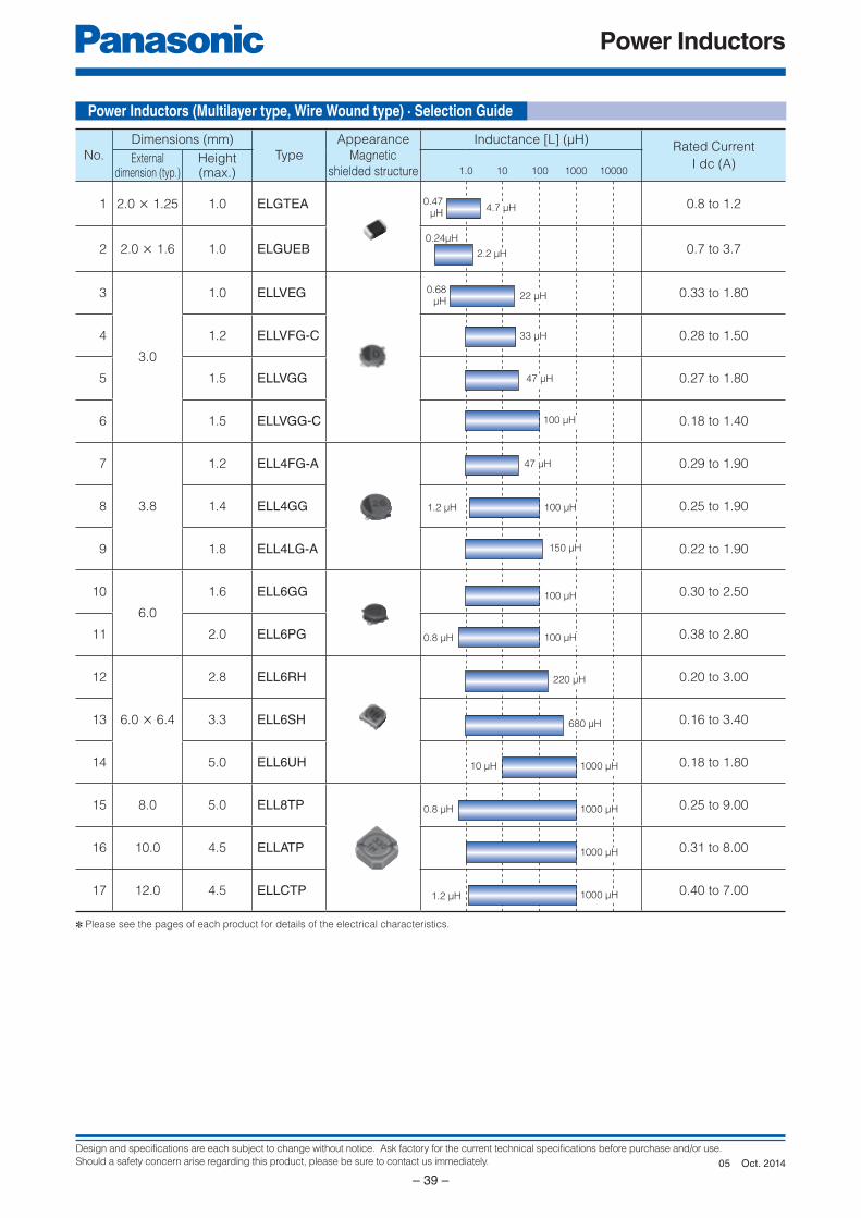
Design and specifications are each subject to change without notice. Ask factory for the current technical specifications before purchase and/or use.
Should a safety concern arise regarding this product, please be sure to contact us immediately.
Power Inductors
– 39 –
Power Inductors (Multilayer type, Wire Wound type) · Selection Guide
No.
Dimensions (mm)
Type
Appearance
Magnetic
shielded structure
Inductance [L] (µH)Rated Current
I dc (A)Externaldimension (typ.)
Height(max.)
1 2.0 × 1.25 1.0 ELGTEA 0.8 to 1.2
2 2.0 × 1.6 1.0 ELGUEB 0.7 to 3.7
3
3.0
1.0 ELLVEG 0.33 to 1.80
4 1.2 ELLVFG-C 0.28 to 1.50
5 1.5 ELLVGG 0.27 to 1.80
6 1.5 ELLVGG-C 0.18 to 1.40
7
3.8
1.2 ELL4FG-A 0.29 to 1.90
8 1.4 ELL4GG 0.25 to 1.90
9 1.8 ELL4LG-A 0.22 to 1.90
10
6.0
1.6 ELL6GG 0.30 to 2.50
11 2.0 ELL6PG 0.38 to 2.80
12
6.0 × 6.4
2.8 ELL6RH 0.20 to 3.00
13 3.3 ELL6SH 0.16 to 3.40
14 5.0 ELL6UH 0.18 to 1.80
15 8.0 5.0 ELL8TP 0.25 to 9.00
16 10.0 4.5 ELLATP 0.31 to 8.00
17 12.0 4.5 ELLCTP 0.40 to 7.00
✽ Please see the pages of each product for details of the electrical characteristics.
22 µH0.68
µH
33 µH
47 µH
100 µH
47 µH
1.2 µH
150 µH
100 µH
100 µH
220 µH
1000 µH
680 µH
1000 µH10 µH
1.0 10 100 1000 10000
1000 µH0.8 µH
100 µH0.8 µH
1.2 µH
1000 µH
4.7 µH
2.2 µH
0.47 µH
0.24µH
Oct. 201405
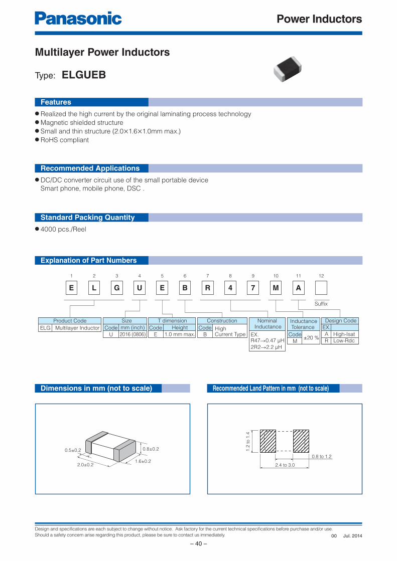
Design and specifications are each subject to change without notice. Ask factory for the current technical specifications before purchase and/or use.
Should a safety concern arise regarding this product, please be sure to contact us immediately.
Power Inductors
– 40 –
E
1
L
2
G
3
U
4
E
5
B
6
R
7
4
8
7
9
M
10
A
11 12
Product Code
ELG Multilayer Inductor
Size
Code
U
mm (inch)
2016 (0806)
T dimension
Code
E
Height
1.0 mm max.
Construction
Code
BHigh Current Type
InductanceTolerance
Code
M±20 %
Design Code
EX.
A
R
High-Isat
Low-Rdc
Nominal Inductance
Suffix
2R2→2.2 µH
R47→0.47 µHEX.
0.5±0.2 0.8±0.2
1.6±0.22.0±0.2
1.2
to 1
.4
2.4 to 3.0
0.8 to 1.2
Explanation of Part Numbers
Dimensions in mm (not to scale)
Features
Recommended Applications
Standard Packing Quantity
Multilayer Power Inductors
Type: ELGUEB
● DC/DC converter circuit use of the small portable device
Smart phone, mobile phone, DSC .
● 4000 pcs./Reel
● Realized the high current by the original laminating process technology ● Magnetic shielded structure● Small and thin structure (2.0×1.6×1.0mm max.)● RoHS compliant
Recommended Land Pattern in mm (not to scale)
Jul. 201400
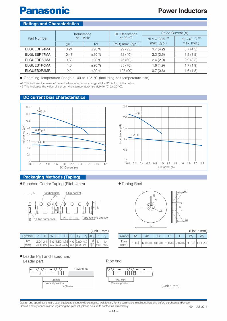
Design and specifications are each subject to change without notice. Ask factory for the current technical specifications before purchase and/or use.
Should a safety concern arise regarding this product, please be sure to contact us immediately.
Power Inductors
– 41 –
t2 Chip component
Feeding hole Chip pocket
fD0
P1 P2 P0 Tape running direction
EF W
B
A
t1E
C
D
A
W1
W2
B
100 min.
Vacant position400 min.
Cover tape
160 min.
Vacant position
Ind
ucta
nce (
µH
)
0
0.1
0.2
0.3
0.4
0.5
0.6
0.8
0.7
0.0 1.50.5 3.41.0 2.0 4.54.03.02.5
DC Current (A)
0.47 µH
0.24 µH
0.68 µH
Ind
ucta
nce (
µH
)
0
0.5
1.0
1.5
2.5
2.0
0.0 1.00.2 0.6 1.41.20.4 0.8 1.6 2.22.01.8
DC Current (A)
1.0 µH
2.2 µH
Ratings and Characteristics
Packaging Methods (Taping)
DC current bias characteristics
Symbol A B W F E P1 P2 P0 0D0 t1 t2
Dim
(mm)2.0±0.2
2.4±0.2
8.0±0.2
3.50±0.05
1.75±0.10
4.0±0.1
2.00±0.05
4.0±0.1
1.5+0.1
0
1.1max.
1.4max.
● Punched Carrier Taping (Pitch 4mm) ● Taping Reel
Symbol 0A 0B C D E W1 W2
Dim(mm)
180–3 60.0±0.5 13.0±0.5 21.0±0.8 2.0±0.5 9.0+1.0 11.4±1.00
0
(Unit : mm)
(Unit : mm) (Unit : mm)
● Leader Part and Taped End
Leader part Tape end
✽1 This indicate the value of current when inductance change dL/L=-30 % from initial value.
✽2 This indicates the value of current when temperature rise dt/t=40 °C (at 20 °C).
● Operating Temperature Range : –40 to 125 °C (Including self-temperature rise)
Part Number
Inductance at 1 MHz
DC Resistanceat 20 °C
Rated Current (A)
dL/L=–30% ✽1
max. (typ.)
dt/t=40 ˚C ✽2
max. (typ.)(µH) Tol. (mΩ) max. (typ.)
ELGUEBR24MA 0.24 ±20 % 29 (22) 3.7 (4.2) 3.7 (4.2)
ELGUEBR47MA 0.47 ±20 % 52 (40) 3.2 (3.5) 3.2 (3.5)
ELGUEBR68MA 0.68 ±20 % 75 (60) 2.4 (2.9) 2.9 (3.3)
ELGUEB1R0MA 1.0 ±20 % 85 (70) 1.6 (1.9) 1.7 (1.9)
ELGUEB2R2MR 2.2 ±20 % 108 (90) 0.7 (0.8) 1.6 (1.8)
Jul. 201400
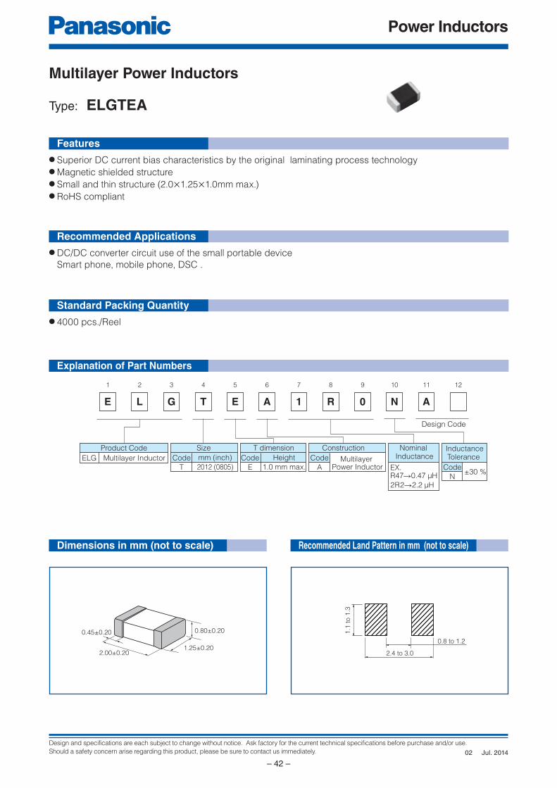
Design and specifications are each subject to change without notice. Ask factory for the current technical specifications before purchase and/or use.
Should a safety concern arise regarding this product, please be sure to contact us immediately.
Power Inductors
– 42 –
E
1
L
2
G
3
T
4
E
5
A
6
1
7
R
8
0
9
N
10
A
11 12
Product Code
ELG Multilayer Inductor
Size
Code
T
mm (inch)
2012 (0805)
T dimension
Code
E
Height
1.0 mm max.
Construction
Code
AMultilayer
Power Inductor
InductanceTolerance
Code
N±30 %
Nominal Inductance
Design Code
2R2→2.2 μH
R47→0.47 μHEX.
0.45±0.20 0.80±0.20
1.25±0.202.00±0.20
1.1
to 1
.3
2.4 to 3.0
0.8 to 1.2
Explanation of Part Numbers
Dimensions in mm (not to scale)
Features
Recommended Applications
Standard Packing Quantity
Multilayer Power Inductors
Type: ELGTEA
● DC/DC converter circuit use of the small portable device
Smart phone, mobile phone, DSC .
● 4000 pcs./Reel
● Superior DC current bias characteristics by the original laminating process technology● Magnetic shielded structure● Small and thin structure (2.0×1.25×1.0mm max.)● RoHS compliant
Recommended Land Pattern in mm (not to scale)
Jul. 201402
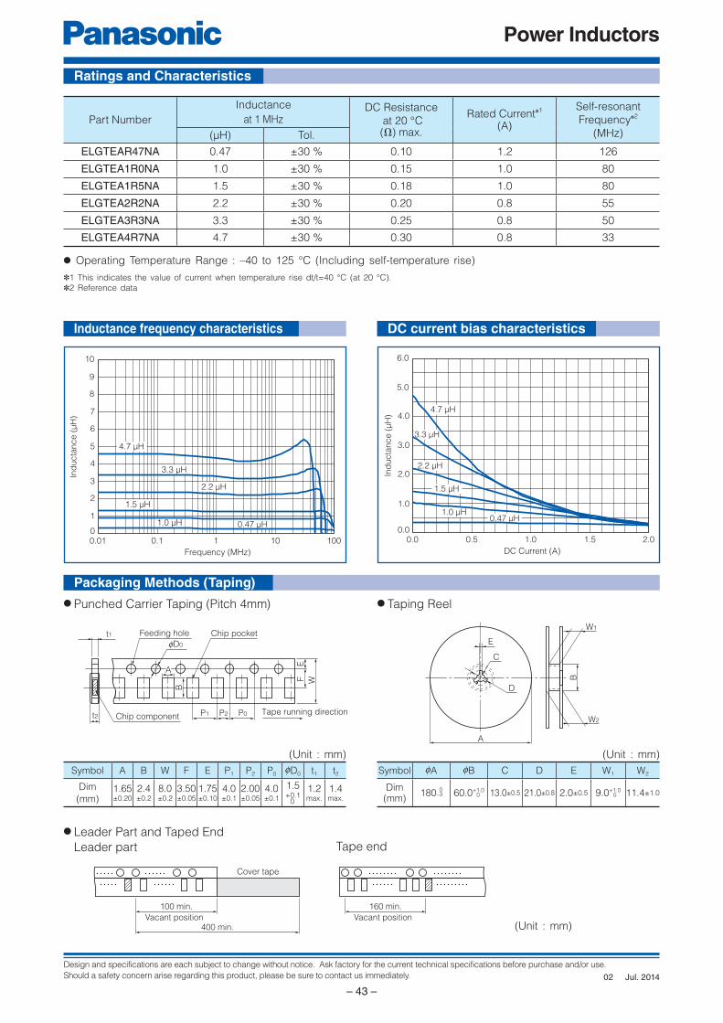
Design and specifications are each subject to change without notice. Ask factory for the current technical specifications before purchase and/or use.
Should a safety concern arise regarding this product, please be sure to contact us immediately.
Power Inductors
– 43 –
Ind
ucta
nce (
μH
)
0
1
2
3
4
5
6
7
8
9
10
0.01 0.1 1 10 100
Frequency (MHz)
1.5 μH
1.0 μH 0.47 μH
4.7 μH
3.3 μH
2.2 μH
Ind
ucta
nce (
μH
)
0.0
1.0
2.0
3.0
4.0
5.0
6.0
0.0 0.5 1.0 1.5 2.0
DC Current (A)
4.7 μH
3.3 μH
2.2 μH
1.5 μH
1.0 μH0.47 μH
t2 Chip component
Feeding hole Chip pocket
fD0
P1 P2 P0 Tape running direction
EF W
B
A
t1E
C
D
A
W1
W2
B
100 min.
Vacant position400 min.
Cover tape
160 min.
Vacant position
Ratings and Characteristics
Inductance frequency characteristics
Packaging Methods (Taping)
DC current bias characteristics
Symbol A B W F E P1 P2 P0 0D0 t1 t2
Dim
(mm)1.65±0.20
2.4±0.2
8.0±0.2
3.50±0.05
1.75±0.10
4.0±0.1
2.00±0.05
4.0±0.1
1.5+0.1
0
1.2max.
1.4max.
● Punched Carrier Taping (Pitch 4mm) ● Taping Reel
Symbol 0A 0B C D E W1 W2
Dim(mm)
180–3 60.0+1.0 13.0±0.5 21.0±0.8 2.0±0.5 9.0+1.0 11.4±1.00
00
(Unit : mm)
(Unit : mm) (Unit : mm)
Part Number
Inductance
at 1 MHzDC Resistance
at 20 °C(Ω) max.
Rated Current✽1
(A)
Self-resonant
Frequency✽2
(MHz)(μH) Tol.
ELGTEAR47NA 0.47 ±30 % 0.10 1.2 126
ELGTEA1R0NA 1.0 ±30 % 0.15 1.0 80
ELGTEA1R5NA 1.5 ±30 % 0.18 1.0 80
ELGTEA2R2NA 2.2 ±30 % 0.20 0.8 55
ELGTEA3R3NA 3.3 ±30 % 0.25 0.8 50
ELGTEA4R7NA 4.7 ±30 % 0.30 0.8 33
✽1 This indicates the value of current when temperature rise dt/t=40 °C (at 20 °C).
✽2 Reference data
● Operating Temperature Range : –40 to 125 °C (Including self-temperature rise)
● Leader Part and Taped End
Leader part Tape end
Jul. 201402
Power Inductors
– 44 –
Multilayer Power Inductors
Type: ELGTEA, ELGUEB
Handling Precautions
Safety PrecautionsMultilayer Power Inductors (hereafter refereed to as “Inductors”) should be used for general purpose applications in consumer electronics (audio/visual, home, office, information & communication) equipment. When subjected to severe electrical, environmental, and/or mechanical stress beyond the specifications, as noted in the Ratings and Specified Conditions section, the Inductors may fail in a short circuit mode or in an open-circuit mode. This case results in a burn-out, smoke or flaming.For products which require high safety levels, please carefully consider how a single malfunction can affect your product. In order to ensure the safety in the case of a single malfunction, please design products with fail-safe, such as setting up protecting circuits, etc. • For the following applications and conditions, please contact us for additional specifications not found in this document.
· When your application may have difficulty complying with the safety or handling precautions specified below. · For any applications where a malfunction with this product may directly or indirectly cause hazardous conditions
which could result in death or injury; 1 Aircraft and Aerospace Equipment (artificial satellite, rocket, etc.) 2 Submarine Equipment (submarine repeating equipment, etc.) 3 Transport Equipment (motor vehicles, airplanes, trains, ship, traffic signal controllers, etc.) 4 Power Generation Control Equipment (atomic power, hydroelectric power, thermal power plant control system, etc.) 5 Medical Equipment (life-support equipment, pacemakers, dialysis controllers, etc.) 6 Information Processing Equipment (large scale computer system, etc.) 7 Electric Heating Appliances, Combustion devices (gas fan heaters, oil fan heaters, etc.) 8 Rotary Motion Equipment 9 Security Systems J And any similar types of equipment
Strict Observance1. Confirmation of Rated Performance
The Inductors shall be operated within the specified rating/performance.Application exceeding the specifications may cause deteriorated performance and/or breakdown, resulting in degradation and/or smoking or ignition of products. The following are strictly observed.(1) The Inductors should be use within the specified operating temperature range including self-fever.(2) The electricity electric current of the inductor should be use in less than rated current.
2. The Inductors shall not be mounted near inflammables.
3. The inductors shall not be bring a magnet and the thing which became magnetized close.
■ Operating Conditions and Circuit Design1. Circuit Design 1.1 Operating Temperature and Storage Temperature
The specified “Operating Temperature Range”
found in the Specif ication is the absolute
maximum and minimum temperature rating. Every
Inductor shall be operated within the specified
“Operating Temperature Range”.
The Inductors mounted on PWB shall be stored
without operating within the specified “Storage
Temperature Range” in the Specifications.
1.2 Operating CurrentThe Inductors shall not be operated in excess of
the “Rated current”. If the Inductors are operated
beyond the specified “Rated current”, it may cause
short and/or damage due to thermal run away.
When high frequency and steep pulse current are
continuously used, even when less than the “Rated
current”, in a circuit, please examine the reliability
of the Inductor while also checking the safety and
reliability of your circuit. Check safety and reliability
in your circuit.
1.3 Self-heatingThe surface temperature of the Inductors shall
be under the specified Maximum Operating
Temperature in the Specifications including the
temperature rise cause by self-heating. Check
temperature rise of the Inductor in your circuit.
Jul. 201402
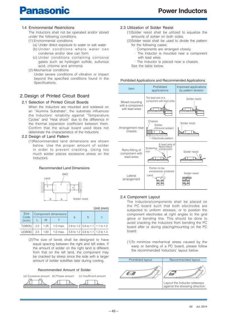
Power Inductors
– 45 –
Land
SMD
ab
c
Solder resist
(a) Excessive amount (b) Proper amount (c) Insufficient amount
Solder resistLand
Portion to be
excessively soldered
A lead wire ofRetro-fittedcomponentSoldering
iron
Solder
(Ground solder)
Chassis
Electrode pattern
Solder resist
Solder resist
Solder resistThe lead wire of a
component with lead wires
1.4 Environmental RestrictionsThe Inductors shall not be operated and/or stored
under the following conditions.
(1) Environmental conditions
(a) Under direct exposure to water or salt water
(b) Under cond i t i ons where wa te r can
condense and/or dew can form
(c) Under conditions containing corrosive
gases such as hydrogen sulfide, sulfurous
acid, chlorine and ammonia
(2) Mechanical conditions
Under severe conditions of vibration or impact
beyond the specified conditions found in the
Specifications.
2. Design of Printed Circuit Board 2.1 Selection of Printed Circuit Boards
When the Inductors are mounted and soldered on
an “Alumina Substrate”, the substrate influences
the Inductors’ reliability against “Temperature
Cycles” and “Heat shock” due to the difference in
the thermal expansion coefficient between them.
Confirm that the actual board used does not
deteriorate the characteristics of the Inductors.
2.2 Design of Land Pattern(1) Recommended land dimensions are shown
below. Use the proper amount of solder
in order to prevent cracking. Using too
much solder places excessive stress on the
Inductors.
Recommended Land Dimensions
Unit (mm)
Size Code(inch)
Component dimensionsa b c
L W T
T(0805) 2.0 1.25 1.0 max. 0.8 to 1.2 0.6 to 1.1 1.1 to 1.3
U(0806) 2.0 1.60 1.0 max. 0.8 to 1.2 0.6 to 1.1 1.2 to 1.4
(2) The size of lands shall be designed to have
equal spacing between the right and left sides. If
the amount of solder on the right land is different
from that on the left land, the component may
be cracked by stress since the side with a larger
amount of solder solidifies later during cooling.
Recommended Amount of Solder
2.3 Utilization of Solder Resist(1) Solder resist shall be utilized to equalize the
amounts of solder on both sides.
(2) Solder resist shall be used to divide the pattern
for the following cases;
· Components are arranged closely.
· The Inductor is mounted near a component
with lead wires.
· The Inductor is placed near a chassis.
See the table below.
Prohibited Applications and Recommended Applications
ItemProhibited
applicationsImproved applications
by pattern division
Mixed mounting with a component
with lead wires
Arrangement near chassis
Retro-fi tting of component with
lead wires
Lateralarrangement
2.4 Component LayoutThe Inductors/components shall be placed on
the PC board such that both electrodes are
subjected to uniform stresses, or to position the
component electrodes at right angles to the grid
glove or bending line. This should be done to
avoid cracking the Inductors from bending the PC
board after or during placing/mounting on the PC
board.
(1) To minimize mechanical stress caused by the
warp or bending of a PC board, please follow
the recommended Inductors’ layout below.
Prohibited layout Recommended layout
Layout the Inductor sideways against the stressing direction.
Jul. 201402
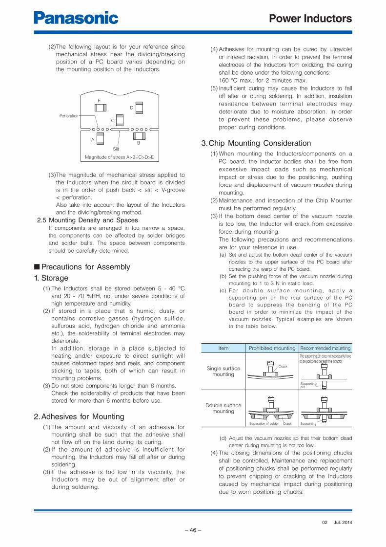
Power Inductors
– 46 –
AB
C
E
D
Slit
Magnitude of stress A>B=C>D>E
Perforation
Supportingpin
SupportingCrackSeparation of solder
Crack
(2) The following layout is for your reference since
mechanical stress near the dividing/breaking
position of a PC board varies depending on
the mounting position of the Inductors.
(3) The magnitude of mechanical stress applied to
the Inductors when the circuit board is divided
is in the order of push back < slit < V-groove
< perforation.
Also take into account the layout of the Inductors
and the dividing/breaking method.
2.5 Mounting Density and SpacesIf components are arranged in too narrow a space,
the components can be affected by solder bridges
and solder balls. The space between components
should be carefully determined.
■ Precautions for Assembly1. Storage
(1) The Inductors shall be stored between 5 - 40 °C
and 20 - 70 %RH, not under severe conditions of
high temperature and humidity.
(2) If stored in a place that is humid, dusty, or
contains corrosive gasses (hydrogen sulfide,
sulfurous acid, hydrogen chloride and ammonia
etc.), the solderability of terminal electrodes may
deteriorate.
In addition, storage in a place subjected to
heating and/or exposure to direct sunlight will
causes deformed tapes and reels, and component
sticking to tapes, both of which can result in
mounting problems.
(3) Do not store components longer than 6 months.
Check the solderability of products that have been
stored for more than 6 months before use.
2. Adhesives for Mounting(1) The amount and viscosity of an adhesive for
mounting shall be such that the adhesive shall
not flow off on the land during its curing.
(2) If the amount of adhesive is insufficient for
mounting, the Inductors may fall off after or during
soldering.
(3) If the adhesive is too low in its viscosity, the
Inductors may be out of alignment after or
during soldering.
(4) Adhesives for mounting can be cured by ultraviolet
or infrared radiation. In order to prevent the terminal
electrodes of the Inductors from oxidizing, the curing
shall be done under the following conditions:
160 °C max., for 2 minutes max.
(5) Insufficient curing may cause the Inductors to fall
off after or during soldering. In addition, insulation
resistance between terminal electrodes may
deteriorate due to moisture absorption. In order
to prevent these problems, please observe
proper curing conditions.
3. Chip Mounting Consideration(1) When mounting the Inductors/components on a
PC board, the Inductor bodies shall be free from
excessive impact loads such as mechanical
impact or stress due to the positioning, pushing
force and displacement of vacuum nozzles during
mounting.
(2) Maintenance and inspection of the Chip Mounter
must be performed regularly.
(3) If the bottom dead center of the vacuum nozzle
is too low, the Inductor will crack from excessive
force during mounting.
The following precautions and recommendations
are for your reference in use.
(a) Set and adjust the bottom dead center of the vacuum
nozzles to the upper surface of the PC board after
correcting the warp of the PC board.
(b) Set the pushing force of the vacuum nozzle during
mounting to 1 to 3 N in static load.
(c) F o r d o u b l e s u r f a c e m o u n t i n g , a p p l y a
supporting pin on the rear surface of the PC
board to suppress the bending of the PC
board in order to minimize the impact of the
vacuum nozzles. Typical examples are shown
in the table below.
Item Prohibited mounting Recommended mounting
Single surface mounting
The supporting pin does not necessarily have to be positioned beneath the Inductor.
Double surface mounting
(d) Adjust the vacuum nozzles so that their bottom dead
center during mounting is not too low.
(4) The closing dimensions of the positioning chucks
shall be controlled. Maintenance and replacement
of positioning chucks shall be performed regularly
to prevent chipping or cracking of the Inductors
caused by mechanical impact during positioning
due to worn positioning chucks.
Jul. 201402
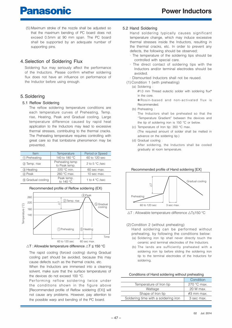
Power Inductors
– 47 –
△T
Preheating
60 to 120 sec 3 sec max.
Gradual cooling
Gradual cooling
5
Heating3
Peak4
Temp. rise
△T 2
Preheating1
260
220
180
140
Tem
pera
ture
(˚C
)
Time
60 to 120 sec 60 sec max.
(5) Maximum stroke of the nozzle shall be adjusted so
that the maximum bending of PC board does not
exceed 0.5mm at 90 mm span. The PC board
shall be supported by an adequate number of
supporting pins.
4. Selection of Soldering FluxSoldering flux may seriously affect the performance
of the Inductors. Please confirm whether soldering
flux does not have an influence on performance of
the Inductor before using enough.
5. Soldering 5.1 Reflow Soldering
The reflow soldering temperature conditions are
each temperature curves of Preheating, Temp.
rise, Heating, Peak and Gradual cooling. Large
temperature difference caused by rapid heat
application to the Inductors may lead to excessive
thermal stresses, contributing to the thermal cracks.
The Preheating temperature requires controlling with
great care so that tombstone phenomenon may be
prevented.
Item Temperature Period or Speed
1 Preheating 140 to 180 °C 60 to 120 sec
2 Temp. risePreheating temp
to Peak temp.2 to 5 °C /sec
3 Heating 220 °C min. 60 sec max.
4 Peak 260 °C max. 10 sec max.
5 Gradual coolingPeak temp. to 140 °C
1 to 4 °C /sec
Recommended profi le of Refl ow soldering (EX)
5.2 Hand SolderingHand soldering typically causes significant
temperature change, which may induce excessive
thermal stresses inside the Inductors, resulting in
the thermal cracks, etc. In order to prevent any
defects, the following should be observed;
· The temperature of the soldering tips should be
controlled with special care.
· The direct contact of soldering tips with the
Inductors and/or terminal electrodes should be
avoided.
· Dismounted Inductors shall not be reused.
(1) Condition 1 (with preheating)(a) Soldering :
01.0 mm Thread eutectic solder with soldering flux✽
in the core.
✽ Ros in -based and non -ac t i va ted f l ux i s
Recommended.
(b) Preheating :
The Inductors shall be preheated so that the
“Temperature Gradient” between the devices and
the tip of soldering iron is 150 °C or below.
(c) Temperature of Iron tip: 350 °C max.
(The required amount of solder shall be melted in
advance on the soldering tip.)
(d) Gradual cooling :
After soldering, the Inductors shall be cooled
gradually at room temperature.
Recommended profi le of Hand soldering [EX]
(2) Condition 2 (without preheating)
Hand soldering can be performed without
preheating, by following the conditions below:(a) Soldering iron tip shall never directly touch the
ceramic and terminal electrodes of the Inductors.
(b) The lands are sufficiently preheated with a
soldering iron tip before sliding the soldering iron
tip to the terminal electrodes of the Inductors for
soldering.
Conditions of Hand soldering without preheating
Condition
Temperature of Iron tip 270 °C max.
Wattage 20 W max.
Shape of Iron tip 03 mm max.
Soldering time with a soldering iron 3 sec max.
△T : Allowable temperature difference △T<150 °C
△T : Allowable temperature difference △T < 150 °C
The rapid cooling (forced cooling) during Gradual
cooling part should be avoided, because this may
cause defects such as the thermal cracks, etc.
When the Inductors are immersed into a cleaning
solvent, make sure that the surface temperatures of
the devices do not exceed 100 °C.
Per fo rming ref low so lder ing t w ice under
the condit ions shown in the f igure above
[Recommended profile of Reflow soldering (EX)] will
not cause any problems. However, pay attention to
the possible warp and bending of the PC board.
Jul. 201402
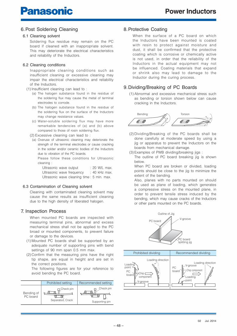
Power Inductors
– 48 –
Supporting pinSeparated, Crack
Check pinCheck pin
Bending Torsion
PC board splitting jig
V-groovePC board
Outline of Jig
PC
boardChip
component
Loadingpoint
V-groove
Loading direction
PC
board Chip component
Loading
point
V-grooveLoading direction
6. Post Soldering Cleaning 6.1 Cleaning solvent
Soldering flux residue may remain on the PC
board if cleaned with an inappropriate solvent.
This may deteriorate the electrical characteristics
and reliability of the Inductors.
6.2 Cleaning conditionsInappropriate cleaning condit ions such as
insufficient cleaning or excessive cleaning may
impair the electrical characteristics and reliability
of the Inductors.
(1) Insufficient cleaning can lead to :(a) The halogen substance found in the residue of
the soldering flux may cause the metal of terminal
electrodes to corrode.
(b) The halogen substance found in the residue of
the soldering flux on the surface of the Inductors
may change resistance values.
(c) Water-soluble soldering flux may have more
remarkable tendencies of (a) and (b) above
compared to those of rosin soldering flux.
(2) Excessive cleaning can lead to :(a) Overuse of ultrasonic cleaning may deteriorate the
strength of the terminal electrodes or cause cracking
in the solder and/or ceramic bodies of the Inductors
due to vibration of the PC boards.
Please follow these conditions for Ultrasonic
cleaning :
Ultrasonic wave output : 20 W/L max.
Ultrasonic wave frequency : 40 kHz max.
Ultrasonic wave cleaning time : 5 min. max.
6.3 Contamination of Cleaning solventCleaning with contaminated cleaning solvent may
cause the same results as insufficient cleaning
due to the high density of liberated halogen.
7. Inspection ProcessWhen mounted PC boards are inspected with
measuring terminal pins, abnormal and excess
mechanical stress shall not be applied to the PC
broad or mounted components, to prevent failure
or damage to the devices.
(1) Mounted PC boards shall be supported by an
adequate number of supporting pins with bend
settings of 90 mm span 0.5 mm max.
(2) Confirm that the measuring pins have the right
tip shape, are equal in height and are set in
the correct positions.
The following figures are for your reference to
avoid bending the PC board.
Prohibited setting Recommended setting
Bending ofPC board
8. Protective CoatingWhen the surface of a PC board on which
the Inductors have been mounted is coated
with resin to protect against moisture and
dust, it shall be confirmed that the protective
coating which is corrosive or chemically active
is not used, in order that the reliability of the
Inductors in the actual equipment may not
be influenced. Coating materials that expand
or shrink also may lead to damage to the
Inductor during the curing process.
9. Dividing/Breaking of PC Boards(1) Abnormal and excessive mechanical stress such
as bending or torsion shown below can cause
cracking in the Inductors.
(2) Dividing/Breaking of the PC boards shall be
done carefully at moderate speed by using a
jig or apparatus to prevent the Inductors on the
boards from mechanical damage.
(3) Examples of PWB dividing/breaking jigs :
The outline of PC board breaking jig is shown
below.
When PC board are broken or divided, loading
points should be close to the jig to minimize the
extent of the bending.
Also, planes with no parts mounted on should
be used as plane of loading, which generates
a compressive stress on the mounted plane, in
order to prevent tensile stress induced by the
bending, which may cause cracks of the Inductors
or other parts mounted on the PC boards.
Prohibited dividing Recommended dividing
Jul. 201402
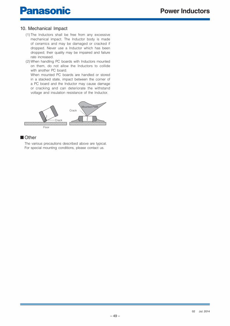
Power Inductors
– 49 –
Floor
Crack
Mounted PWB
Crack
10. Mechanical Impact(1) The Inductors shall be free from any excessive
mechanical impact. The Inductor body is made
of ceramics and may be damaged or cracked if
dropped. Never use a Inductor which has been
dropped; their quality may be impaired and failure
rate increased.
(2) When handling PC boards with Inductors mounted
on them, do not allow the Inductors to collide
with another PC board.
When mounted PC boards are handled or stored
in a stacked state, impact between the corner of
a PC board and the Inductor may cause damage
or cracking and can deteriorate the withstand
voltage and insulation resistance of the Inductor.
■ OtherThe various precautions described above are typical.
For special mounting conditions, please contact us.
Jul. 201402
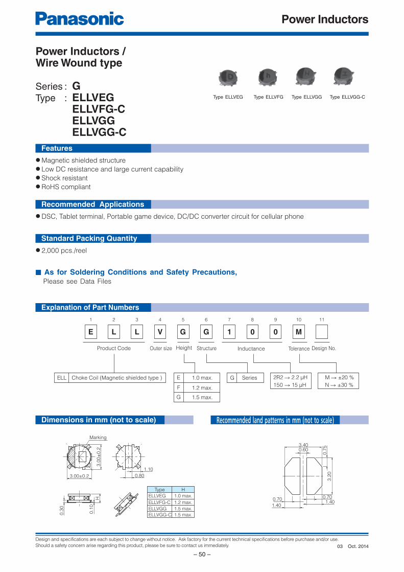
Design and specifications are each subject to change without notice. Ask factory for the current technical specifications before purchase and/or use.
Should a safety concern arise regarding this product, please be sure to contact us immediately.
Power Inductors
– 50 –
E
1
L
2
L
3
V
4
G
5
G
6
1
7
0
8 9
M
10 11
0
Product Code Design No.InductanceStructureOuter size
Choke Coil (Magnetic shielded type ) SeriesGELL
Height
E 1.0 max.
G 1.5 max.
F 1.2 max.150 → 15 µH
M → ±20 %
N → ±30 %
2R2 → 2.2 µH
Tolerance
Marking
1.5 max.
1.2 max.
1.0 max.
ELLVGG-C
ELLVFG-C
ELLVEG
HType
1.5 max.ELLVGG
3.00±0.2
3.0
0±
0.2
0.80
1.10
0.3
0
0.1
0
H 0.700.701.40
1.40
0.7
53.2
0
3.400.60
Explanation of Part Numbers
Features
Recommended Applications
Standard Packing Quantity
● Magnetic shielded structure● Low DC resistance and large current capability● Shock resistant● RoHS compliant
● DSC, Tablet terminal, Portable game device, DC/DC converter circuit for cellular phone
● 2,000 pcs./reel
■ As for Soldering Conditions and Safety Precautions, Please see Data Files
Power Inductors / Wire Wound type
Series : GType : ELLVEG ELLVFG-C ELLVGG ELLVGG-C
Type ELLVEG Type ELLVFG Type ELLVGG Type ELLVGG-C
Dimensions in mm (not to scale) Recommended land patterns in mm (not to scale)
Oct. 201403
Design and specifications are each subject to change without notice. Ask factory for the current technical specifications before purchase and/or use.
Should a safety concern arise regarding this product, please be sure to contact us immediately.
Power Inductors
– 51 –
Standard Parts
✽1 Saturation Rated Current : This DC current which causes a 30 % inductance reduction from its nominal value.✽2 Temperature Rise Current : This indicates the value of current when temperature rise dt/t= 40 °C (at 20 °C).
Series Part No.
Inductance(100 kHz)
RDC
(at 20 °C)Saturation Rated
Current✽1
(mA max.)
TemperatureRise Current✽2
(mA max.)Marking
(µH) Tol. (mΩ) Tol.
Series
VEG
ELLVEGR68N 0.68
±30 %
50
±20 %
1950 1800 7
ELLVEG1R0N 1.0 61 1900 1600 A
ELLVEG1R5N 1.5 74 1200 1400 C
ELLVEG2R2N 2.2 110 1100 1250 D
ELLVEG3R3N 3.3 210 1000 820 E
ELLVEG4R7N 4.7 240 750 770 H
ELLVEG6R8N 6.8 350 580 650 K
ELLVEG100M 10.0
±20 %
480 520 600 M
ELLVEG150M 15.0 710 430 490 O
ELLVEG220M 22.0 1200 330 400 R
Series
VFG-C
ELLVFG1R0NC 1.0
±30 %
50 1500 1700 a
ELLVFG1R5NC 1.5 61 1300 1550 c
ELLVFG2R2NC 2.2 87 1100 1400 d
ELLVFG3R3NC 3.3 110 980 1250 e
ELLVFG4R7NC 4.7 150 740 1050 h
ELLVFG6R8NC 6.8 230 600 840 k
ELLVFG100MC 10.0
±20 %
380 550 640 m
ELLVFG150MC 15.0 540 500 480 o
ELLVFG220MC 22.0 710 350 430 r
ELLVFG330MC 33.0 1160 280 330 t
Series
VGG
ELLVGG1R0N 1.0
±30 %
52 2200 1800 A
ELLVGG1R2N 1.2 61 2000 1600 B
ELLVGG1R6N 1.6 73 1800 1550 C
ELLVGG2R2N 2.2 92 1600 1400 D
ELLVGG3R3N 3.3 130 1350 1100 E
ELLVGG3R9N 3.9 150 1300 1000 F
ELLVGG4R7N 4.7 170 1200 980 H
ELLVGG6R8N 6.8 230 1000 800 K
ELLVGG100M 10.0
±20 %
280 800 730 M
ELLVGG120M 12.0 480 690 580 N
ELLVGG150M 15.0 640 600 490 O
ELLVGG220M 22.0 800 500 460 R
ELLVGG330M 33.0 1330 450 340 T
ELLVGG470M 47.0 2100 350 270 V
Series
VGG-C
ELLVGG1R0NC 1.0
±30 %
47 1400 2000 A
ELLVGG2R2NC 2.2 79 1050 1500 D
ELLVGG3R3NC 3.3 110 1000 1300 E
ELLVGG4R7NC 4.7 130 900 1200 H
ELLVGG6R8NC 6.8 180 700 1000 K
ELLVGG100MC 10.0
±20 %
260 600 860 M
ELLVGG120MC 12.0 280 550 730 N
ELLVGG150MC 15.0 420 450 670 O
ELLVGG220MC 22.0 530 410 600 R
ELLVGG330MC 33.0 790 350 450 T
ELLVGG470MC 47.0 1200 260 360 V
ELLVGG101MC 100 2950 180 250 Z
Oct. 201403
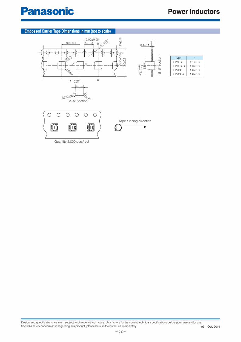
Design and specifications are each subject to change without notice. Ask factory for the current technical specifications before purchase and/or use.
Should a safety concern arise regarding this product, please be sure to contact us immediately.
Power Inductors
– 52 –
Quantity 2,000 pcs./reel
Tape running direction
A–A' Section
3.3±0.1
R0.20 max. R0.10
4.0 ° max.
3.3±
0.1
0.4±0.1
t
tType
4.0
° m
ax.
B–B
' S
ection
R0.20
R0.60
2.00±0.054.0±0.1
5.5
0±
0.0
5
12.0
±0.3
1.75
±0.
10
A A,
BB
,
f1.50+0.1
08.0±0.1
ELLVEG
ELLVFG-C
ELLVGG
ELLVGG-C
1.1±0.3
1.3±0.3
1.6±0.3
1.6±0.3
Embossed Carrier Tape Di men sions in mm (not to scale)
Oct. 201403
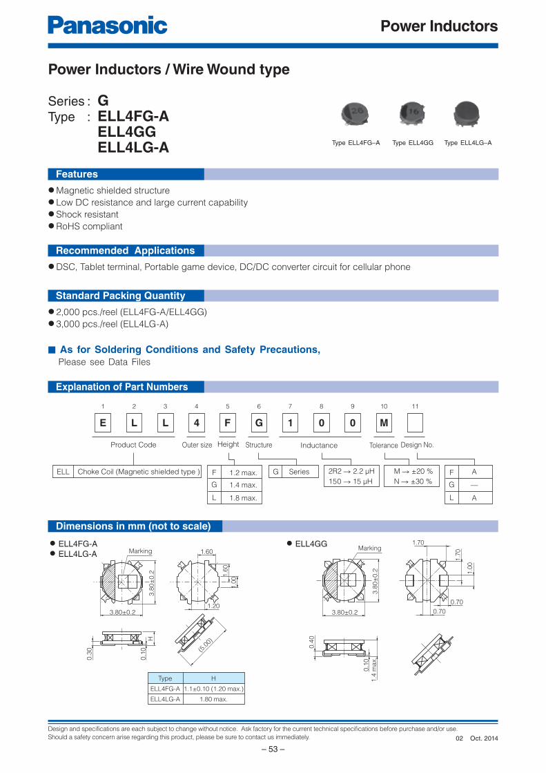
Design and specifications are each subject to change without notice. Ask factory for the current technical specifications before purchase and/or use.
Should a safety concern arise regarding this product, please be sure to contact us immediately.
Power Inductors
– 53 –
E
1
L
2
L
3
4 1 0 0
4
F
5
G
6 7 8 9
M
10 11
Product Code Design No.InductanceStructureOuter size
Choke Coil (Magnetic shielded type ) SeriesGELL
Height
G 1.4 max.
L 1.8 max.
F 1.2 max.150 → 15 µH
M → ±20 %
N → ±30 %
2R2 → 2.2 µH
Tolerance
G —
L A
F A
H
1.1±0.10 (1.20 max.)
1.80 max.
Type
ELL4FG-A
ELL4LG-A
Marking
3.8
0±
0.2
0.3
0
0.1
0 (5.0
0)
3.80±0.21.20
1.60
1.6
0
1.0
0
H
0.70
0.70
0.4
0
3.8
0±
0.2
3.80±0.2
1.0
0
1.7
0
1.70
0.1
0
1.4
max.
Marking
Explanation of Part Numbers
Features
Recommended Applications
Standard Packing Quantity
● Magnetic shielded structure● Low DC resistance and large current capability● Shock resistant● RoHS compliant
● DSC, Tablet terminal, Portable game device, DC/DC converter circuit for cellular phone
● 2,000 pcs./reel (ELL4FG-A/ELL4GG)● 3,000 pcs./reel (ELL4LG-A)
■ As for Soldering Conditions and Safety Precautions, Please see Data Files
Power Inductors / Wire Wound type
Series : GType : ELL4FG-A ELL4GG ELL4LG-A
Dimensions in mm (not to scale)
Type ELL4FG–A Type ELL4GG Type ELL4LG–A
● ELL4FG-A
● ELL4LG-A
● ELL4GG
Oct. 201402
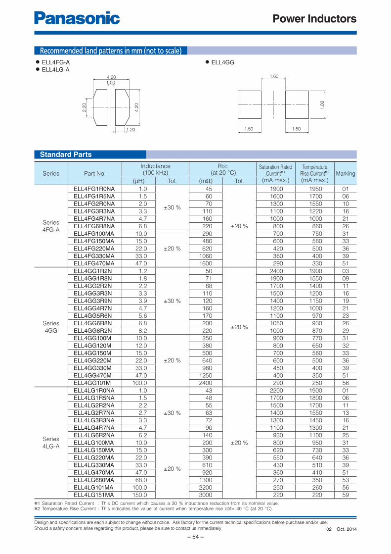
Design and specifications are each subject to change without notice. Ask factory for the current technical specifications before purchase and/or use.
Should a safety concern arise regarding this product, please be sure to contact us immediately.
Power Inductors
– 54 –
1.20
4.2
0
2.2
0
4.201.00
1.60
1.501.50
1.8
0
Standard Parts
✽1 Saturation Rated Current : This DC current which causes a 30 % inductance reduction from its nominal value.✽2 Temperature Rise Current : This indicates the value of current when temperature rise dt/t= 40 °C (at 20 °C).
Series Part No.
Inductance(100 kHz)
RDC
(at 20 °C)Saturation Rated
Current✽1
(mA max.)
TemperatureRise Current✽2
(mA max.)Marking
(µH) Tol. (mΩ) Tol.
Series
4FG-A
ELL4FG1R0NA 1.0
±30 %
45
±20 %
1900 1950 01
ELL4FG1R5NA 1.5 60 1600 1700 06
ELL4FG2R0NA 2.0 70 1300 1550 10
ELL4FG3R3NA 3.3 110 1100 1220 16
ELL4FG4R7NA 4.7 160 1000 1000 21
ELL4FG6R8NA 6.8 220 800 860 26
ELL4FG100MA 10.0
±20 %
290 700 750 31
ELL4FG150MA 15.0 480 600 580 33
ELL4FG220MA 22.0 620 420 500 36
ELL4FG330MA 33.0 1060 360 400 39
ELL4FG470MA 47.0 1600 290 330 51
Series
4GG
ELL4GG1R2N 1.2
±30 %
50
±20 %
2400 1900 03
ELL4GG1R8N 1.8 71 1900 1550 09
ELL4GG2R2N 2.2 88 1700 1400 11
ELL4GG3R3N 3.3 110 1500 1200 16
ELL4GG3R9N 3.9 120 1400 1150 19
ELL4GG4R7N 4.7 160 1200 1000 21
ELL4GG5R6N 5.6 170 1100 970 23
ELL4GG6R8N 6.8 200 1050 930 26
ELL4GG8R2N 8.2 220 1000 870 29
ELL4GG100M 10.0
±20 %
250 900 770 31
ELL4GG120M 12.0 380 800 650 32
ELL4GG150M 15.0 500 700 580 33
ELL4GG220M 22.0 640 600 500 36
ELL4GG330M 33.0 980 450 400 39
ELL4GG470M 47.0 1250 400 350 51
ELL4GG101M 100.0 2400 290 250 56
Series
4LG-A
ELL4LG1R0NA 1.0
±30 %
43
±20 %
2200 1900 01
ELL4LG1R5NA 1.5 48 1700 1800 06
ELL4LG2R2NA 2.2 55 1500 1700 11
ELL4LG2R7NA 2.7 63 1400 1550 13
ELL4LG3R3NA 3.3 72 1300 1450 16
ELL4LG4R7NA 4.7 90 1100 1300 21
ELL4LG6R2NA 6.2 140 930 1100 25
ELL4LG100MA 10.0
±20 %
200 800 950 31
ELL4LG150MA 15.0 300 620 730 33
ELL4LG220MA 22.0 390 550 640 36
ELL4LG330MA 33.0 610 430 510 39
ELL4LG470MA 47.0 920 360 410 51
ELL4LG680MA 68.0 1300 270 350 53
ELL4LG101MA 100.0 2200 250 260 56
ELL4LG151MA 150.0 3000 220 220 59
Recommended land patterns in mm (not to scale)● ELL4FG-A
● ELL4LG-A
● ELL4GG
Oct. 201402
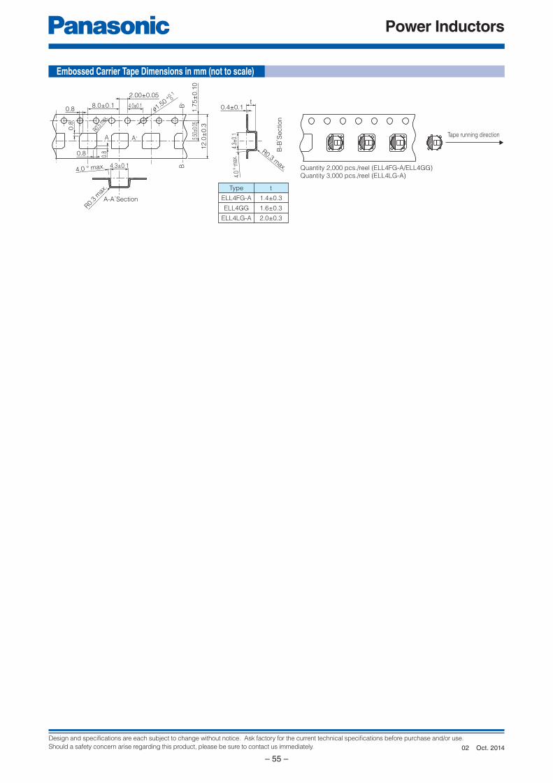
Design and specifications are each subject to change without notice. Ask factory for the current technical specifications before purchase and/or use.
Should a safety concern arise regarding this product, please be sure to contact us immediately.
Power Inductors
– 55 –
0.4±0.1t
2.00±0.05
4.0±0.1
1.7
5±
0.1
0
B,
f1.50+0.1
0
8.0±0.1
0.8
0.8
0.8
0.8
Quantity 2,000 pcs./reel (ELL4FG-A/ELL4GG)
Quantity 3,000 pcs./reel (ELL4LG-A)
Tape running direction
R0.3 max.
4.3±
0.1
4.0
° m
ax.
B-B
, Se
ctio
n
5.50
±0.0
5
12
.0±
0.3
A-A,Section
4.3±0.1
R0.
3 m
ax.
R0.5 m
ax.
4.0 ° max. B
A A,
t
1.4±0.3
1.6±0.3
2.0±0.3
Type
ELL4FG-A
ELL4GG
ELL4LG-A
Embossed Carrier Tape Di men sions in mm (not to scale)
Oct. 201402
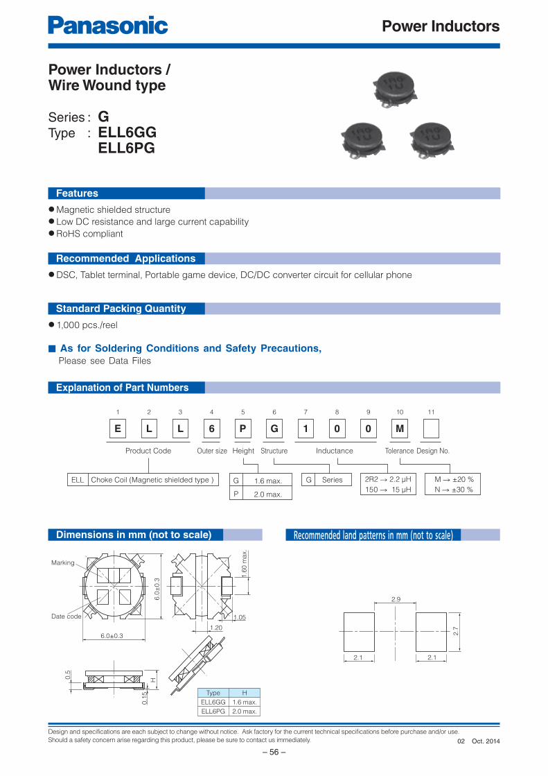
Design and specifications are each subject to change without notice. Ask factory for the current technical specifications before purchase and/or use.
Should a safety concern arise regarding this product, please be sure to contact us immediately.
Power Inductors
– 56 –
Marking
Date code
6.0±0.3
6.0
±0.3
0.5
H
0.1
5
1.6
0 m
ax.
1.05
1.20
Type
ELL6GG
ELL6PG
H
1.6 max.
2.0 max.
2.9
2.1 2.1
2.7
E
1
L
2
L
3
6
4
P
5
G
6 7 8 9
M
10 11
1 0 0
Product Code Design No.InductanceStructureOuter size
Choke Coil (Magnetic shielded type ) SeriesGELL
Height
G 1.6 max.150 → 15 µH
M → ±20 %
N → ±30 %
2R2 → 2.2 µH
Tolerance
P 2.0 max.
Explanation of Part Numbers
Features
Recommended Applications
Standard Packing Quantity
● Magnetic shielded structure● Low DC resistance and large current capability● RoHS compliant
● DSC, Tablet terminal, Portable game device, DC/DC converter circuit for cellular phone
● 1,000 pcs./reel
■ As for Soldering Conditions and Safety Precautions, Please see Data Files
Power Inductors / Wire Wound type
Series : GType : ELL6GG ELL6PG
Dimensions in mm (not to scale) Recommended land patterns in mm (not to scale)
Oct. 201402
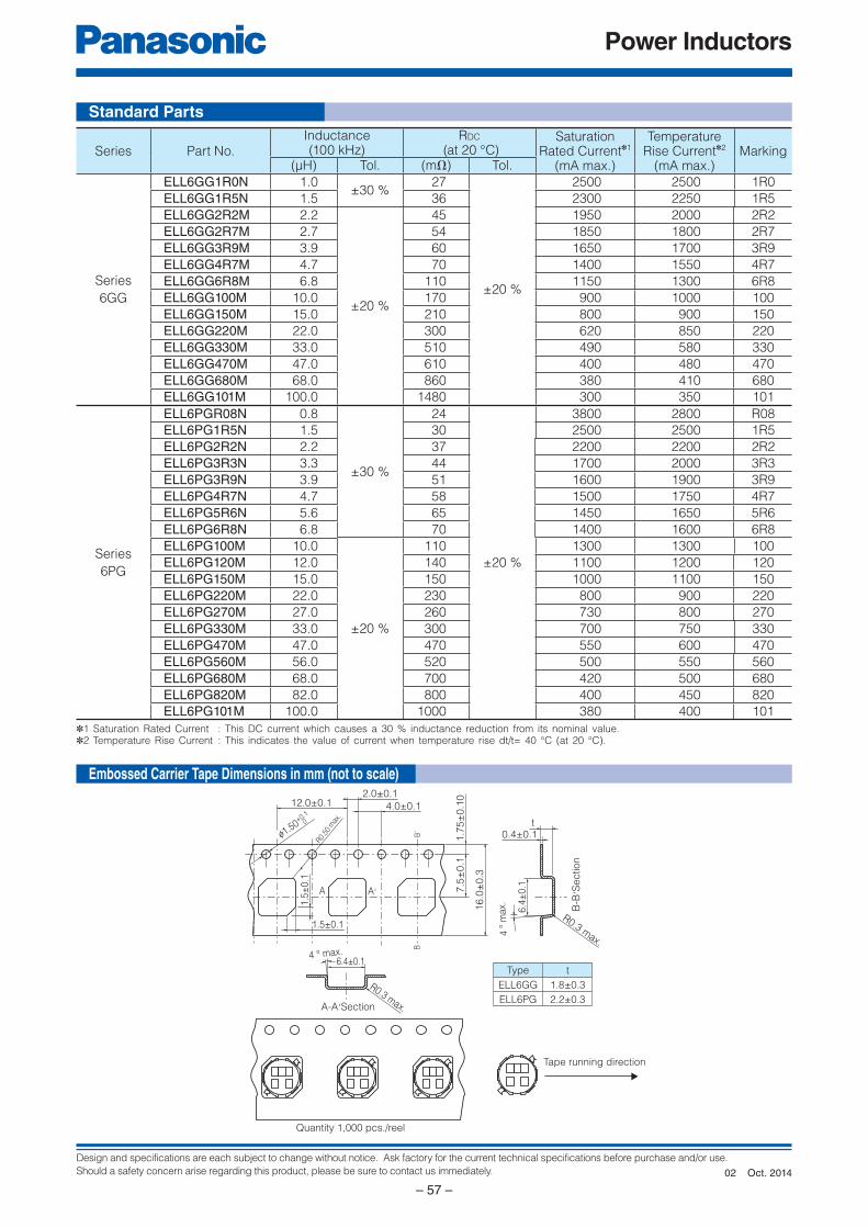
Design and specifications are each subject to change without notice. Ask factory for the current technical specifications before purchase and/or use.
Should a safety concern arise regarding this product, please be sure to contact us immediately.
Power Inductors
– 57 –
Standard Parts
Embossed Carrier Tape Di men sions in mm (not to scale)
✽1 Saturation Rated Current : This DC current which causes a 30 % inductance reduction from its nominal value.✽2 Temperature Rise Current : This indicates the value of current when temperature rise dt/t= 40 °C (at 20 °C).
Type
ELL6GG
ELL6PG
t
1.8±0.3
2.2±0.3
Tape running direction
Quantity 1,000 pcs./reel
0.4±0.1t
2.0±0.1
4.0±0.112.0±0.1
R0.3 max.
R0.3 max.
6.4
±0.1
6.4±0.1
4 °
max.
1.7
5±
0.1
07.5
±0.1
1.5
±0.1
1.5±0.1
16.0
±0.3
A-A,Section
R0.50
max
.
4 ° max.
B,
B
A A,
f1.50+0.1
0
B-B
, Section
Series Part No.Inductance(100 kHz)
RDC
(at 20 °C)Saturation
Rated Current✽1
(mA max.)
TemperatureRise Current✽2
(mA max.)Marking
(µH) Tol. (mΩ) Tol.
Series
6GG
ELL6GG1R0N 1.0±30 %
27
±20 %
2500 2500 1R0
ELL6GG1R5N 1.5 36 2300 2250 1R5
ELL6GG2R2M 2.2
±20 %
45 1950 2000 2R2
ELL6GG2R7M 2.7 54 1850 1800 2R7
ELL6GG3R9M 3.9 60 1650 1700 3R9
ELL6GG4R7M 4.7 70 1400 1550 4R7
ELL6GG6R8M 6.8 110 1150 1300 6R8
ELL6GG100M 10.0 170 900 1000 100
ELL6GG150M 15.0 210 800 900 150
ELL6GG220M 22.0 300 620 850 220
ELL6GG330M 33.0 510 490 580 330
ELL6GG470M 47.0 610 400 480 470
ELL6GG680M 68.0 860 380 410 680
ELL6GG101M 100.0 1480 300 350 101
Series
6PG
ELL6PGR08N 0.8
±30 %
24
±20 %
3800 2800 R08
ELL6PG1R5N 1.5 30 2500 2500 1R5
ELL6PG2R2N 2.2 37 2200 2200 2R2
ELL6PG3R3N 3.3 44 1700 2000 3R3
ELL6PG3R9N 3.9 51 1600 1900 3R9
ELL6PG4R7N 4.7 58 1500 1750 4R7
ELL6PG5R6N 5.6 65 1450 1650 5R6
ELL6PG6R8N 6.8 70 1400 1600 6R8
ELL6PG100M 10.0
±20 %
110 1300 1300 100
ELL6PG120M 12.0 140 1100 1200 120
ELL6PG150M 15.0 150 1000 1100 150
ELL6PG220M 22.0 230 800 900 220
ELL6PG270M 27.0 260 730 800 270
ELL6PG330M 33.0 300 700 750 330
ELL6PG470M 47.0 470 550 600 470
ELL6PG560M 56.0 520 500 550 560
ELL6PG680M 68.0 700 420 500 680
ELL6PG820M 82.0 800 400 450 820
ELL6PG101M 100.0 1000 380 400 101
Oct. 201402
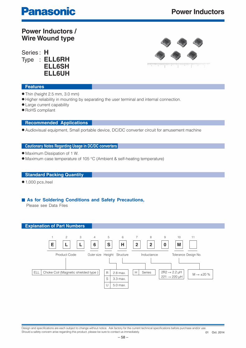
Design and specifications are each subject to change without notice. Ask factory for the current technical specifications before purchase and/or use.
Should a safety concern arise regarding this product, please be sure to contact us immediately.
Power Inductors
– 58 –
E
1
L
2
L
3
6
4 5
H
6
2
7
2
8
0
9
M
10 11
S
Product Code Design No.InductanceStructureOuter size
Choke Coil (Magnetic shielded type ) SeriesHELL
Height
R 2.8 max.
S 3.3 max.
U 5.0 max.
221 → 220 µHM → ±20 %
2R2 → 2.2 µH
Tolerance
Explanation of Part Numbers
Features
Recommended Applications
Cautionary Notes Regarding Usage in DC/DC converters
Standard Packing Quantity
● Thin (height 2.5 mm, 3.0 mm)● Higher reliability in mounting by separating the user terminal and internal connection.● Large current capability● RoHS compliant
● Audiovisual equipment, Small portable device, DC/DC converter circuit for amusement machine
● Maximum Dissipation of 1 W.● Maximum case temperature of 105 °C (Ambient & self-heating temperature)
● 1,000 pcs./reel
■ As for Soldering Conditions and Safety Precautions, Please see Data Files
Power Inductors / Wire Wound type
Series : HType : ELL6RH ELL6SH ELL6UH
Oct. 201401

Design and specifications are each subject to change without notice. Ask factory for the current technical specifications before purchase and/or use.
Should a safety concern arise regarding this product, please be sure to contact us immediately.
Power Inductors
– 59 –
6.0±0.5
6.4±0.5
H
2.5 mm±0.3 mm
3.0 mm±0.3 mm
5.0 mm max.
Type
ELL6RH
ELL6SH
ELL6UH
0.1
50
.05
(0.9)
H3
.0±
0.3
6.0
±0
.5
3.8
4.0
7.4
0
Marking
Date Code
Standard Parts
Part No.
Inductance (µH)
at 100 kHz
Tol. ±20 %
RDC (mΩ)
at 20 °C
Tol. ±20 %
RatedCurrent✽
(mA) max.Marking
6RH 6SH 6RH 6SH
ELL6□H1R0M 1.0 19 19 3000 3400 1R0
ELL6□H1R5M 1.5 24 24 2400 3200 1R5
ELL6□H2R0M 2.0 — 26 — 2600 2R0
ELL6□H2R2M 2.2 30 — 2300 — 2R2
ELL6□H2R7M 2.7 39 31 1800 2400 2R7
ELL6□H3R3M 3.3 44 34 1600 2200 3R3
ELL6□H4R7M 4.7 49 42 1580 2000 4R7
ELL6□H5R1M 5.1 56 — 1550 — 5R1
ELL6□H5R6M 5.6 — 49 — 1800 5R6
ELL6□H6R2M 6.2 62 — 1400 — 6R2
ELL6□H6R8M 6.8 — 52 — 1500 6R8
ELL6□H7R5M 7.5 80 — 1250 — 7R5
ELL6□H8R2M 8.2 87 61 1200 1400 8R2
ELL6□H100M 10.0 95 65 1100 1300 100
ELL6□H120M 12.0 130 71 1000 1200 120
ELL6□H150M 15.0 150 96 850 1100 150
ELL6□H180M 18.0 170 130 800 1000 180
ELL6□H220M 22.0 220 140 700 900 220
ELL6□H270M 27.0 260 160 650 800 270
ELL6□H330M 33.0 380 180 600 700 330
ELL6□H390M 39.0 410 240 550 650 390
ELL6□H470M 47.0 480 270 500 600 470
ELL6□H560M 56.0 540 290 450 550 560
ELL6□H680M 68.0 770 520 400 500 680
ELL6□H820M 82.0 870 600 350 450 820
ELL6□H101M 100.0 1000 680 300 400 101
ELL6□H121M 120.0 1500 750 280 370 121
ELL6□H151M 150.0 1800 860 250 350 151
ELL6□H181M 180.0 2000 1300 230 300 181
ELL6□H221M 220.0 2300 1400 200 280 221
ELL6□H271M 270.0 — 2400 — 260 271
ELL6□H331M 330.0 — 2700 — 240 331
ELL6□H391M 390.0 — 2800 — 210 391
ELL6□H471M 470.0 — 3200 — 200 471
ELL6□H561M 560.0 — 3700 — 180 561
ELL6□H681M 680.0 — 4300 — 160 681✽ Current : This indicates the value of current when the inductance is 80% of nominal value or when the case temperature has risen 45 °C.
Dimensions in mm (not to scale) Connections (Top view)
Recommended land patterns in mm (not to scale)
Oct. 201401
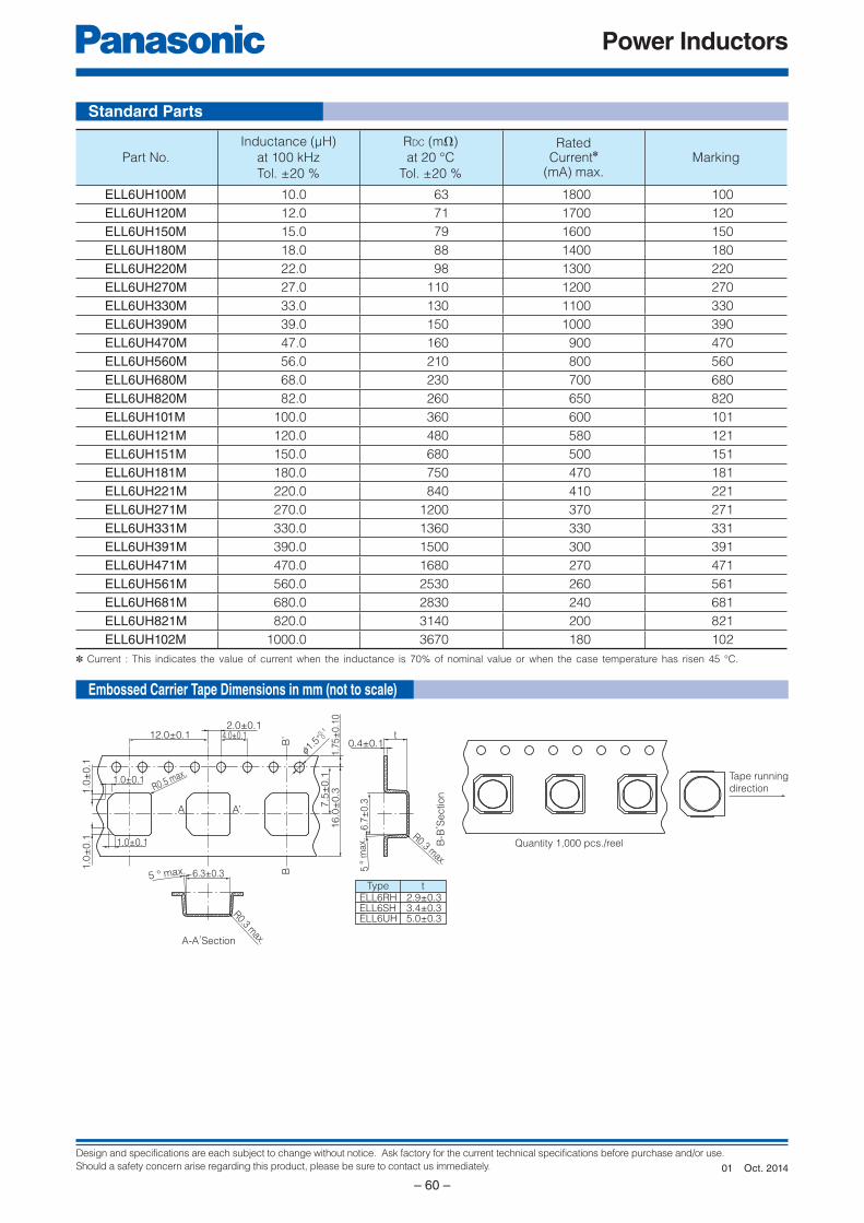
Design and specifications are each subject to change without notice. Ask factory for the current technical specifications before purchase and/or use.
Should a safety concern arise regarding this product, please be sure to contact us immediately.
Power Inductors
– 60 –
tTypeELL6RH 2.9±0.3ELL6SH 3.4±0.3ELL6UH 5.0±0.3
Quantity 1,000 pcs./reel
Tape running
direction
B-B
, Section
A-A,Section
1.0
±0.1
1.0
±0.1 1.0±0.1
6.3±0.35 ° max.
R0.3 max.
1.0±0.1R0.5 max.
A A’
6.7
±0.3
5 °
max.
R0.3 max.
B’
B
12.0±0.12.0±0.1
4.0±0.10.4±0.1
t
f1.5
+0.10
1.7
5±
0.1
07.5
±0.1
16.0
±0.3
Standard Parts
Part No.
Inductance (µH)
at 100 kHz
Tol. ±20 %
RDC (mΩ)
at 20 °C
Tol. ±20 %
RatedCurrent✽
(mA) max.Marking
ELL6UH100M 10.0 63 1800 100
ELL6UH120M 12.0 71 1700 120
ELL6UH150M 15.0 79 1600 150
ELL6UH180M 18.0 88 1400 180
ELL6UH220M 22.0 98 1300 220
ELL6UH270M 27.0 110 1200 270
ELL6UH330M 33.0 130 1100 330
ELL6UH390M 39.0 150 1000 390
ELL6UH470M 47.0 160 900 470
ELL6UH560M 56.0 210 800 560
ELL6UH680M 68.0 230 700 680
ELL6UH820M 82.0 260 650 820
ELL6UH101M 100.0 360 600 101
ELL6UH121M 120.0 480 580 121
ELL6UH151M 150.0 680 500 151
ELL6UH181M 180.0 750 470 181
ELL6UH221M 220.0 840 410 221
ELL6UH271M 270.0 1200 370 271
ELL6UH331M 330.0 1360 330 331
ELL6UH391M 390.0 1500 300 391
ELL6UH471M 470.0 1680 270 471
ELL6UH561M 560.0 2530 260 561
ELL6UH681M 680.0 2830 240 681
ELL6UH821M 820.0 3140 200 821
ELL6UH102M 1000.0 3670 180 102
✽ Current : This indicates the value of current when the inductance is 70% of nominal value or when the case temperature has risen 45 °C.
Embossed Carrier Tape Di men sions in mm (not to scale)
Oct. 201401
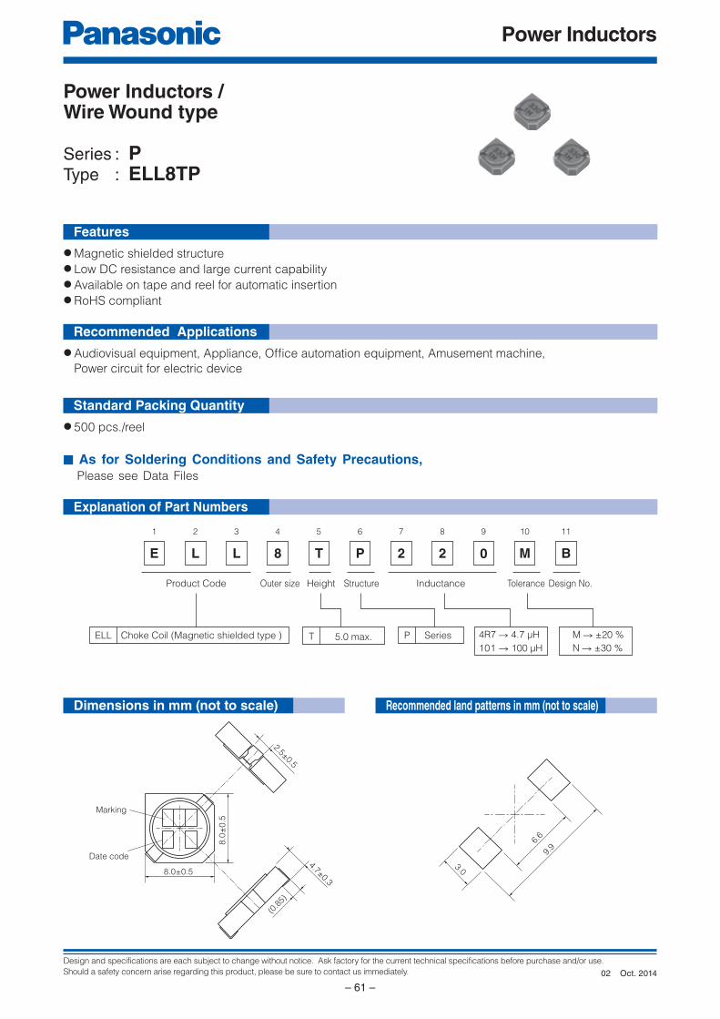
Design and specifications are each subject to change without notice. Ask factory for the current technical specifications before purchase and/or use.
Should a safety concern arise regarding this product, please be sure to contact us immediately.
Power Inductors
– 61 –
2.5±0.5
4.7±0.3
(0.8
5)
8.0±0.5
8.0
±0.5
Marking
Date code
6.6
9.9
3.0
E
1
L
2
L
3
8
4
T
5
P
6
2
7
2
8 9
M
10
B
11
0
Product Code Design No.InductanceStructureOuter size
Choke Coil (Magnetic shielded type ) SeriesPELL
Height
T 5.0 max.101 → 100 µH
M → ±20 %
N → ±30 %
4R7 → 4.7 µH
Tolerance
Explanation of Part Numbers
Features
Recommended Applications
Standard Packing Quantity
● Magnetic shielded structure● Low DC resistance and large current capability● Available on tape and reel for automatic insertion● RoHS compliant
● Audiovisual equipment, Appliance, Offi ce automation equipment, Amusement machine,
Power circuit for electric device
● 500 pcs./reel
■ As for Soldering Conditions and Safety Precautions, Please see Data Files
Power Inductors / Wire Wound type
Series : PType : ELL8TP
Dimensions in mm (not to scale) Recommended land patterns in mm (not to scale)
Oct. 201402
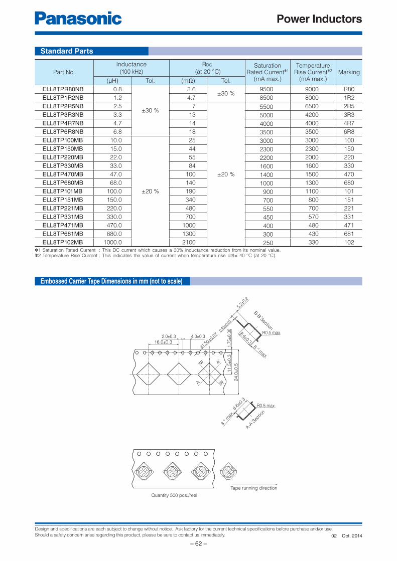
Design and specifications are each subject to change without notice. Ask factory for the current technical specifications before purchase and/or use.
Should a safety concern arise regarding this product, please be sure to contact us immediately.
Power Inductors
– 62 –
8 ° max.
8.6±0.3
5.2±0
.2
0.40±
0.05
R0.5 max.
8 ° m
ax.
8.6±0
.3
R0.5 max.
2.0±0.3 4.0±0.3
B
B’A
A’
16.0±0.3
11.5
±0.3
1.7
5±0.3
0
24.0
±0.5
f1.50±0.0
7
B-B ,Section
A-A, Sec
tion
Quantity 500 pcs./reel
Tape running direction
Standard Parts
Embossed Carrier Tape Di men sions in mm (not to scale)
✽1 Saturation Rated Current : This DC current which causes a 30% inductance reduction from its nominal value.✽2 Temperature Rise Current : This indicates the value of current when temperature rise dt/t= 40 °C (at 20 °C).
Part No.
Inductance
(100 kHz)
RDC
(at 20 °C)Saturation
Rated Current✽1
(mA max.)
TemperatureRise Current✽2
(mA max.)Marking
(µH) Tol. (mΩ) Tol.
ELL8TPR80NB 0.8
±30 %
3.6±30 %
9500 9000 R80
ELL8TP1R2NB 1.2 4.7 8500 8000 1R2
ELL8TP2R5NB 2.5 7
±20 %
5500 6500 2R5
ELL8TP3R3NB 3.3 13 5000 4200 3R3
ELL8TP4R7NB 4.7 14 4000 4000 4R7
ELL8TP6R8NB 6.8 18 3500 3500 6R8
ELL8TP100MB 10.0
±20 %
25 3000 3000 100
ELL8TP150MB 15.0 44 2300 2300 150
ELL8TP220MB 22.0 55 2200 2000 220
ELL8TP330MB 33.0 84 1600 1600 330
ELL8TP470MB 47.0 100 1400 1500 470
ELL8TP680MB 68.0 140 1000 1300 680
ELL8TP101MB 100.0 190 900 1100 101
ELL8TP151MB 150.0 340 700 800 151
ELL8TP221MB 220.0 480 550 700 221
ELL8TP331MB 330.0 700 450 570 331
ELL8TP471MB 470.0 1000 400 480 471
ELL8TP681MB 680.0 1300 300 430 681
ELL8TP102MB 1000.0 2100 250 330 102
Oct. 201402
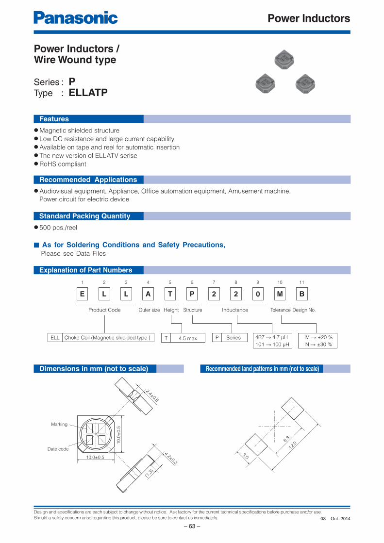
Design and specifications are each subject to change without notice. Ask factory for the current technical specifications before purchase and/or use.
Should a safety concern arise regarding this product, please be sure to contact us immediately.
Power Inductors
– 63 –
E
1
L
2
L
3
A
4
T
5
P
6
2
7
2
8 9
M
10
B
11
0
Product Code Design No.InductanceStructureOuter size
Choke Coil (Magnetic shielded type ) SeriesPELL
Height
T 4.5 max.101 → 100 µH
M → ±20 %
N → ±30 %
4R7 → 4.7 µH
Tolerance
2.4±0.5
(1.3
)
10.0±0.5
10.0
±0.5
Marking
Date code4.2±0.3
8.3
12.0
3.0
Explanation of Part Numbers
Features
Recommended Applications
Standard Packing Quantity
● Magnetic shielded structure● Low DC resistance and large current capability● Available on tape and reel for automatic insertion● The new version of ELLATV serise● RoHS compliant
● Audiovisual equipment, Appliance, Offi ce automation equipment, Amusement machine,
Power circuit for electric device
● 500 pcs./reel
■ As for Soldering Conditions and Safety Precautions, Please see Data Files
Power Inductors / Wire Wound type
Series : PType : ELLATP
Dimensions in mm (not to scale) Recommended land patterns in mm (not to scale)
Oct. 201403

Design and specifications are each subject to change without notice. Ask factory for the current technical specifications before purchase and/or use.
Should a safety concern arise regarding this product, please be sure to contact us immediately.
Power Inductors
– 64 –
2.0±0.3 4.0±0.3
16.0±0.3
11.5
±0.3
1.7
5±0.3
0
24.0
±0.5
10.6
±0.3
8 °
max.
4.8±0.30.4±0.1
R0.5 max.
f1.5+0.1
0
Quantity 500 pcs./reel
Tape running direction
Standard Parts
Embossed Carrier Tape Di men sions in mm (not to scale)
✽1 Saturation Rated Current : This DC current which causes a 30% inductance reduction from its nominal value.✽2 Temperature Rise Current : This indicates the value of current when temperature rise dt/t= 40 °C (at 20 °C).
Part No.
Inductance
(100 kHz)
RDC
(at 20 °C)Saturation
Rated Current✽1
(mA max.)
TemperatureRise Current✽2
(mA max.)Marking
(µH) Tol. (mΩ) Tol.
ELLATP1R0NB 1.0
±30 %
3.6
±30 %
9000 8000 1R0
ELLATP1R5NB 1.5 4.4 8000 7000 1R5
ELLATP2R7NB 2.7 6.4 5500 6500 2R7
ELLATP3R3NB 3.3 7.5 5350 5500 3R3
ELLATP4R7NB 4.7 9.1 4500 5000 4R7
ELLATP5R1NB 5.1 12
±20 %
4350 4500 5R1
ELLATP6R8NB 6.8 15 4000 4000 6R8
ELLATP8R2NB 8.2 18 3700 3700 8R2
ELLATP100MB 10.0
±20 %
22 3300 3300 100
ELLATP120MB 12.0 25 2900 2900 120
ELLATP150MB 15.0 29 2700 2700 150
ELLATP220MB 22.0 38 2200 2500 220
ELLATP270MB 27.0 47 1900 2200 270
ELLATP330MB 33.0 59 1800 2000 330
ELLATP390MB 39.0 66 1600 1800 390
ELLATP470MB 47.0 80 1500 1700 470
ELLATP680MB 68.0 120 1100 1400 680
ELLATP820MB 82.0 140 1050 1300 820
ELLATP101MB 100.0 180 1000 1200 101
ELLATP121MB 120.0 200 900 1000 121
ELLATP151MB 150.0 250 780 900 151
ELLATP181MB 180.0 320 750 750 181
ELLATP221MB 220.0 360 700 700 221
ELLATP331MB 330.0 550 550 600 331
ELLATP471MB 470.0 780 470 500 471
ELLATP681MB 680.0 1150 380 450 681
ELLATP102MB 1000.0 1700 310 370 102
Oct. 201403
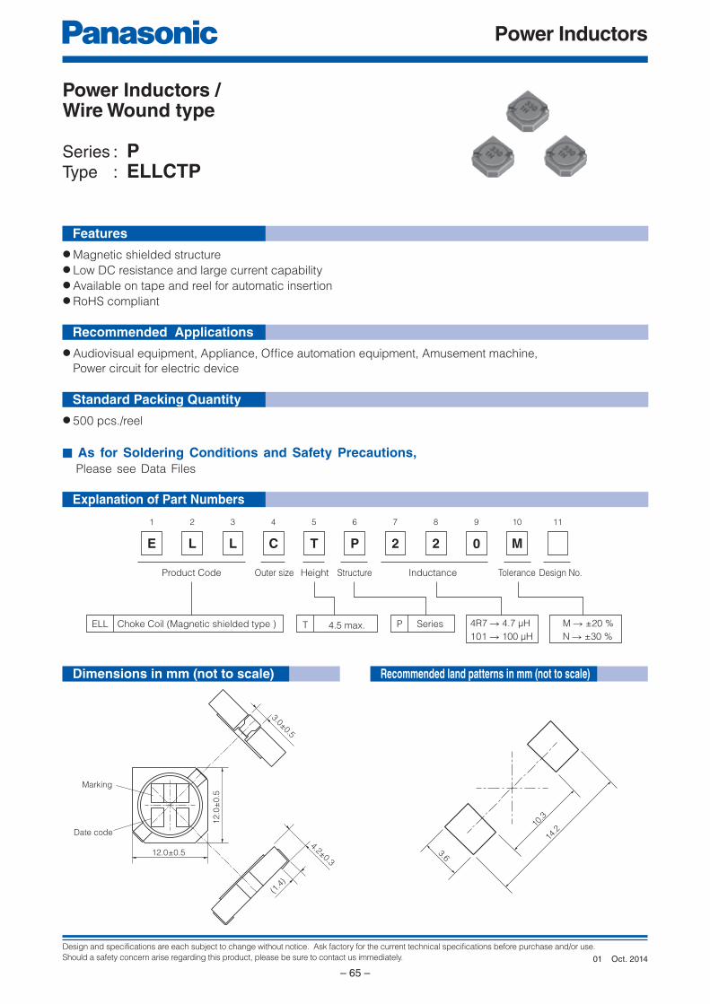
Design and specifications are each subject to change without notice. Ask factory for the current technical specifications before purchase and/or use.
Should a safety concern arise regarding this product, please be sure to contact us immediately.
Power Inductors
– 65 –
E
1
L
2
L
3
C
4
T
5
P
6
2
7
2
8 9
M
10 11
0
Product Code Design No.InductanceStructureOuter size
Choke Coil (Magnetic shielded type ) SeriesPELL
Height
T 4.5 max.101 → 100 µH
M → ±20 %
N → ±30 %
4R7 → 4.7 µH
Tolerance
3.0±0.5
(1.4
)
12.0±0.5
12.0
±0.5
Marking
Date code
4.2±0.3
14.2
10.3
3.6
Explanation of Part Numbers
Features
Recommended Applications
Standard Packing Quantity
● Magnetic shielded structure● Low DC resistance and large current capability● Available on tape and reel for automatic insertion● RoHS compliant
● Audiovisual equipment, Appliance, Offi ce automation equipment, Amusement machine,
Power circuit for electric device
● 500 pcs./reel
■ As for Soldering Conditions and Safety Precautions, Please see Data Files
Power Inductors / Wire Wound type
Series : PType : ELLCTP
Dimensions in mm (not to scale) Recommended land patterns in mm (not to scale)
Oct. 201401
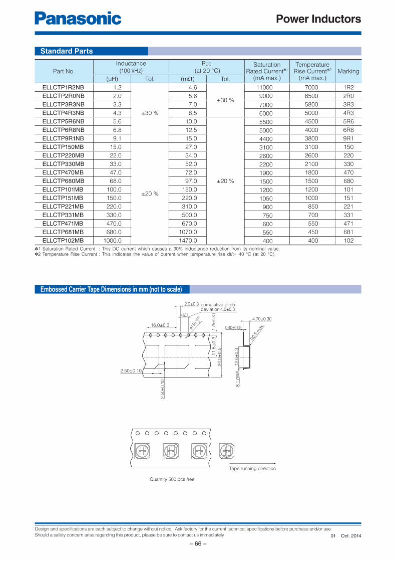
Design and specifications are each subject to change without notice. Ask factory for the current technical specifications before purchase and/or use.
Should a safety concern arise regarding this product, please be sure to contact us immediately.
Power Inductors
– 66 –
Quantity 500 pcs./reel
Tape running direction
4.0±0.3cumulative pitchdeviation
2.50±0.10
2.5
0±
0.1
0
16.0±0.3
11.5
±0.3
1.75
±0.
30
24.0
±0.5
12
.6±
0.3
8 °
max.
4.70±0.30
0.40±0.05
R0.
5 m
ax.
2.0±0.3
4.0±0.3
f1.50
+0.10
0
Standard Parts
Embossed Carrier Tape Di men sions in mm (not to scale)
✽1 Saturation Rated Current : This DC current which causes a 30% inductance reduction from its nominal value.✽2 Temperature Rise Current : This indicates the value of current when temperature rise dt/t= 40 °C (at 20 °C).
Part No.
Inductance
(100 kHz)
RDC
(at 20 °C)Saturation
Rated Current✽1
(mA max.)
TemperatureRise Current✽2
(mA max.)Marking
(µH) Tol. (mΩ) Tol.
ELLCTP1R2NB 1.2
±30 %
4.6
±30 %
11000 7000 1R2
ELLCTP2R0NB 2.0 5.6 9000 6500 2R0
ELLCTP3R3NB 3.3 7.0 7000 5800 3R3
ELLCTP4R3NB 4.3 8.5 6000 5000 4R3
ELLCTP5R6NB 5.6 10.0
±20 %
5500 4500 5R6
ELLCTP6R8NB 6.8 12.5 5000 4000 6R8
ELLCTP9R1NB 9.1 15.0 4400 3800 9R1
ELLCTP150MB 15.0
±20 %
27.0 3100 3100 150
ELLCTP220MB 22.0 34.0 2600 2600 220
ELLCTP330MB 33.0 52.0 2200 2100 330
ELLCTP470MB 47.0 72.0 1900 1800 470
ELLCTP680MB 68.0 97.0 1500 1500 680
ELLCTP101MB 100.0 150.0 1200 1200 101
ELLCTP151MB 150.0 220.0 1050 1000 151
ELLCTP221MB 220.0 310.0 900 850 221
ELLCTP331MB 330.0 500.0 750 700 331
ELLCTP471MB 470.0 670.0 600 550 471
ELLCTP681MB 680.0 1070.0 550 450 681
ELLCTP102MB 1000.0 1470.0 400 400 102
Oct. 201401
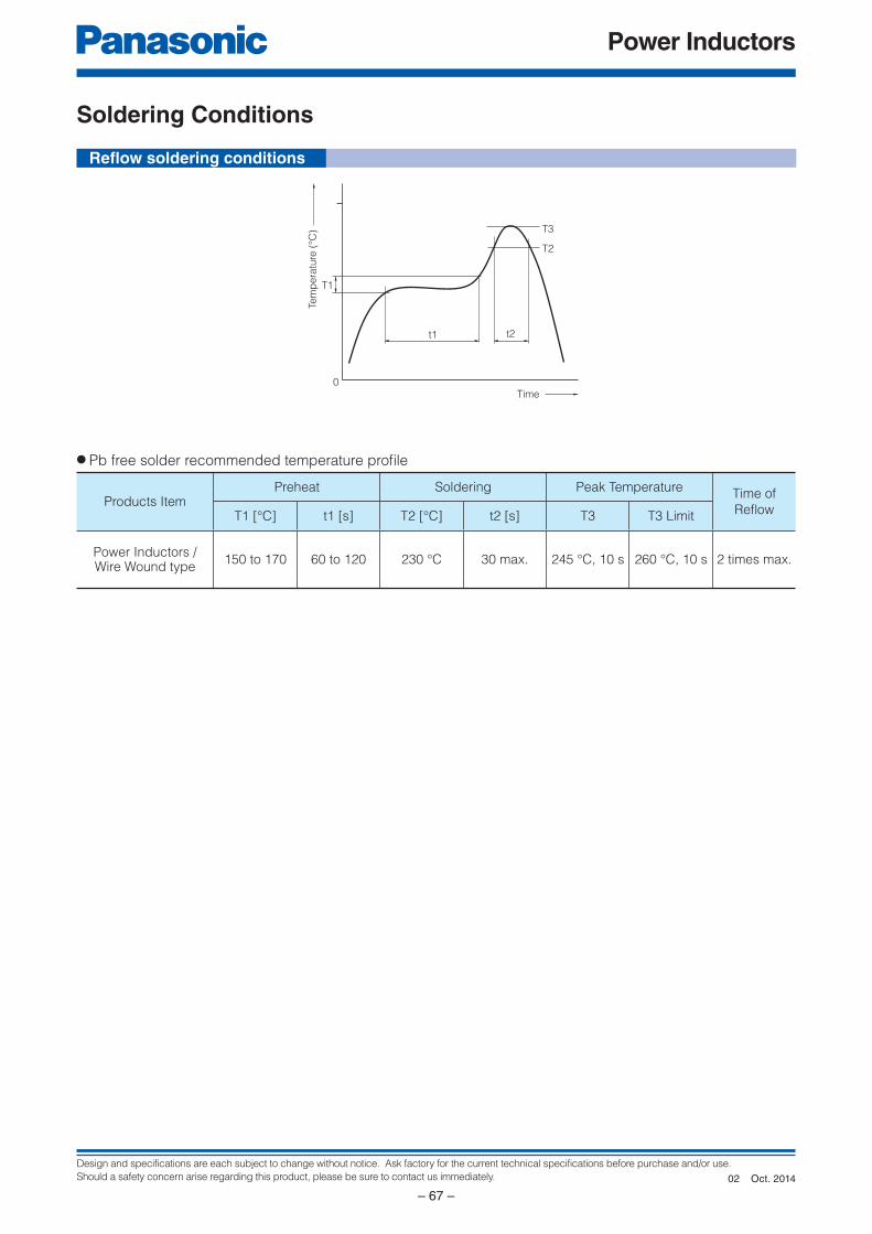
Design and specifications are each subject to change without notice. Ask factory for the current technical specifications before purchase and/or use.
Should a safety concern arise regarding this product, please be sure to contact us immediately.
Power Inductors
– 67 –
t2
Tem
pe
ratu
re (
°C)
Time
T3
T2
T1
t1
0
Refl ow soldering conditions
Soldering Conditions
Products ItemPreheat Soldering Peak Temperature
Time of
Refl owT1 [°C] t1 [s] T2 [°C] t2 [s] T3 T3 Limit
Power Inductors / Wire Wound type
150 to 170 60 to 120 230 °C 30 max. 245 °C, 10 s 260 °C, 10 s 2 times max.
● Pb free solder recommended temperature profi le
Oct. 201402
Design and specifications are each subject to change without notice. Ask factory for the current technical specifications before purchase and/or use.
Should a safety concern arise regarding this product, please be sure to contact us immediately.
Power Inductors
– 68 –
Precautions for use
1. Operation range and environments
1 These products are designed and manufactured for general and stan dard use in general elec tron icequipment (e.g. AV equipment, home electric ap pli anc es, office equipment, information and com mu ni ca tion
equipment)
2 These products are not intended for use in the following special conditions. Be fore using the products, care ful ly check the effects on their quality and performance, and determine whether or not they can be used.
• In liquid, such as water, oil, chemicals, or organic solvent
• In direct sunlight, outdoors, or in dust
• In salty air or air with a high concentration of corrosive gas, such as Cl2, H2S, NH3, SO2, or NO2
• In an environment where these products cause dew condensation
2. Handling
1 Do not bring magnets or magnetized materials close to the product. The influence of their magnetic field can change the inductance value.
2 Do not apply strong mechanical shocks by either dropping or collision with other parts. Excessive shock can damage the part.
3. Washing of boardKindly consult the Technical department before washing of the PWB with any cleansing agent, and provide the
washing condition.
4. Resoldering with a soldering ironThe temperature of the tip of the soldering iron should be 360 °C or less, 4 seconds.
And resoldering with a soldering iron should be limited to 1 time, and after that should be cooling these.
5. Mounting sideExternal force must be less than 5.0 [N] : while mounting.
6. Storage conditionsNormal temperature (–5 to 35 °C), normal humidity (85 % RH max.), shall not be exposed to direct sunlight and
harmful gases and care should be taken so as not to cause dew.
Safety Precautions (Common precautions for Power Inductors / Wire Wound type)
• When using our products, no matter what sort of equipment they might be used for, be sure to make a written
agreement on the specifications with us in advance. The design and specifications in this catalog are subject
to change without prior notice.
• Do not use the products beyond the specifications described in this catalog.
• This catalog explains the quality and performance of the products as individual components. Be fore use, check
and evaluate their operations when installed in your products.
• Install the following systems for a failsafe design to ensure safety if these products are to be used in equip ment
where a defect in these products may cause the loss of human life or other significant damage, such as damage
to vehicles (au to mo bile, train, vessel), traffic lights, medical equipment, aerospace equipment, elec tric heating
ap pli anc es, com bus tion/gas equipment, rotating equipment, and disaster/crime prevention equip ment.
✽ Systems equipped with a protection circuit and a protection device
✽ Systems equipped with a redundant circuit or other system to prevent an unsafe status in the event of a single fault
<Package markings>
Package markings include the product number, quantity, and country of origin.
In principle, the country of origin should be indicated in English.
Sep. 201402
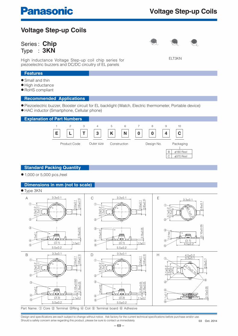
Design and specifications are each subject to change without notice. Ask factory for the current technical specifications before purchase and/or use.
Should a safety concern arise regarding this product, please be sure to contact us immediately.
Voltage Step-up Coils
– 69 –
(3.1) 1.2±0.1
5.5±0.2
1.5±
0.1
0.18
±0.
05
3.3
±0.2
1.2
±0
.1
3.3±0.1
0.6±
0.1
0.85
±0.
10
1
2
3
4
5
(3.3) 1.1±0.2
5.5±0.2
1.65
±0.
20
0.18
±0.
05
0.25
±0.
05
3.3
±0.2
3.3±0.1
0.6±
0.1
0.85
±0.
10
1
2
3
4
5
1.2
±0
.1
(3.3) 1.1±0.2
5.5±0.2
1.4±
0.2
0.18
±0.
05
0.12
5±0.
050
3.3
±0.2
1.2
±0
.1
3.3±0.1
0.6±
0.1
0.85
±0.
10
1
2
3
4
5
(3.1) 1.2±0.1
5.5±0.2
2.0
±0.2
0.18
±0.
05
3.3
±0.2
1.2
±0
.1
3.3±0.1
0.6±
0.1
0.85
±0.
10
1
2
3
4
5
(3.1)4.5±0.2
3.3±0.1
f3.1
±0.2
0.1
0±
0.0
5
3.1
±0.2
1.4
max
.1.2
±0.1 0.8
±0.1
1
2
3
4
5
E
1
L
2
T
3
3
4
K
5
N
6
0
7
0
8
4
9
B
C
f180 Reel
f370 Reel
Product Code Outer size Construction Design No. Packaging
C
10
1.1±
0.1
0.1
0±
0.0
5
3.1
±0.2
2.5
±0.1
1.2
±0.1 0
.8±
0.1
4.5±0.23.3±0.1
2.73±0.10
1
6
4
5
2
Explanation of Part Numbers
Features
Recommended Applications
Standard Packing Quantity
Dimensions in mm (not to scale)
● Small and thin● High inductance● RoHS compliant
● Piezoelectric buzzer, Booster circuit for EL backlight (Watch, Electric thermometer, Portable device)● HAC inductor (Smartphone, Cellular phone)
● 1,000 or 5,000 pcs./reel
Voltage Step-up Coils
Series : ChipType : 3KN
ELT3KN
Part Name: 1 Core 2 Terminal 3Ring 4 Coil 5 Terminal board 6 Adhesive
● Type 3KN
A
B
C
D
E
H
High inductance Voltage Step-up coil chip series forpiezoelectric buzzers and DC/DC circuitry of EL panels
Oct. 201403
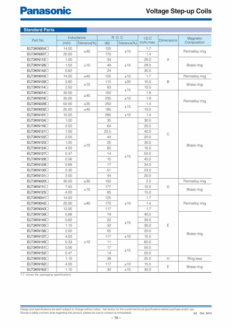
Design and specifications are each subject to change without notice. Ask factory for the current technical specifications before purchase and/or use.
Should a safety concern arise regarding this product, please be sure to contact us immediately.
Voltage Step-up Coils
– 70 –
Standard Parts
“□” shows the packaging specifications.
Part No.Inductance R. D. C I.D.C
(mA) max.Dimensions
MagneticComposition(mH) Tolerance(%) (Ω) Tolerance(%)
ELT3KN004□ 14.00±40
125±10
1.7
A
Permalloy ringELT3KN007□ 20.00 170 1.4
ELT3KN113□ 1.00
±10
34
±15
25.0
Brass ringELT3KN126□ 1.50 49 29.0
ELT3KN142□ 0.82 24 30.0
ELT3KN019□ 14.00 ±40 125 ±10 1.7
B
Permalloy ring
ELT3KN109□ 3.80±10
115 ±20 15.0Brass ring
ELT3KN114□ 2.50 83±15
15.0
ELT3KN014□ 30.00±40
150 1.9
C
Permalloy ringELT3KN018□ 35.00 235 ±10 1.9
ELT3KN028□ 50.00 ±35 250±15
1.4
ELT3KN032□ 25.00 ±40 185 10.0
ELT3KN101□ 10.00
±10
285 ±10 1.4
Brass ring
ELT3KN104□ 1.00 35
±15
30.0
ELT3KN118□ 2.50 64 20.0
ELT3KN121□ 1.00 22.5 40.0
ELT3KN122□ 2.00 44 20.0
ELT3KN123□ 1.00 25 30.0
ELT3KN124□ 4.00 85 15.0
ELT3KN127□ 0.47 14 50.0
ELT3KN128□ 0.56 15 45.0
ELT3KN129□ 0.68 17 34.0
ELT3KN130□ 2.30 51 23.0
ELT3KN131□ 2.00 44 20.0
ELT3KN020□ 30.00 ±30 150 2.5
D
Permalloy ring
ELT3KN111□ 7.50±10
177 10.0Brass ring
ELT3KN125□ 4.00 85 15.0
ELT3KN041□ 14.00
±40
125
±10
1.7
E
Permalloy ringELT3KN042□ 20.00 175 1.4
ELT3KN043□ 12.00 117 1.7
ELT3KN139□ 0.68
±10
19
±15
40.0
Brass ring
ELT3KN140□ 0.82 22 30.0
ELT3KN135□ 1.10 32 30.0
ELT3KN136□ 2.00 55 20.0
ELT3KN137□ 4.00 117 ±10 15.0
ELT3KN149□ 0.33 11
±15
60.0
ELT3KN151□ 0.56 17 50.0
ELT3KN152□ 0.47 14 50.0
ELT3KN155□ 1.10 38 25.0 H Ring less
ELT3KN162□ 4.00 117 ±10 15.0E Brass ring
ELT3KN163□ 1.10 32 ±15 30.0
Oct. 201403
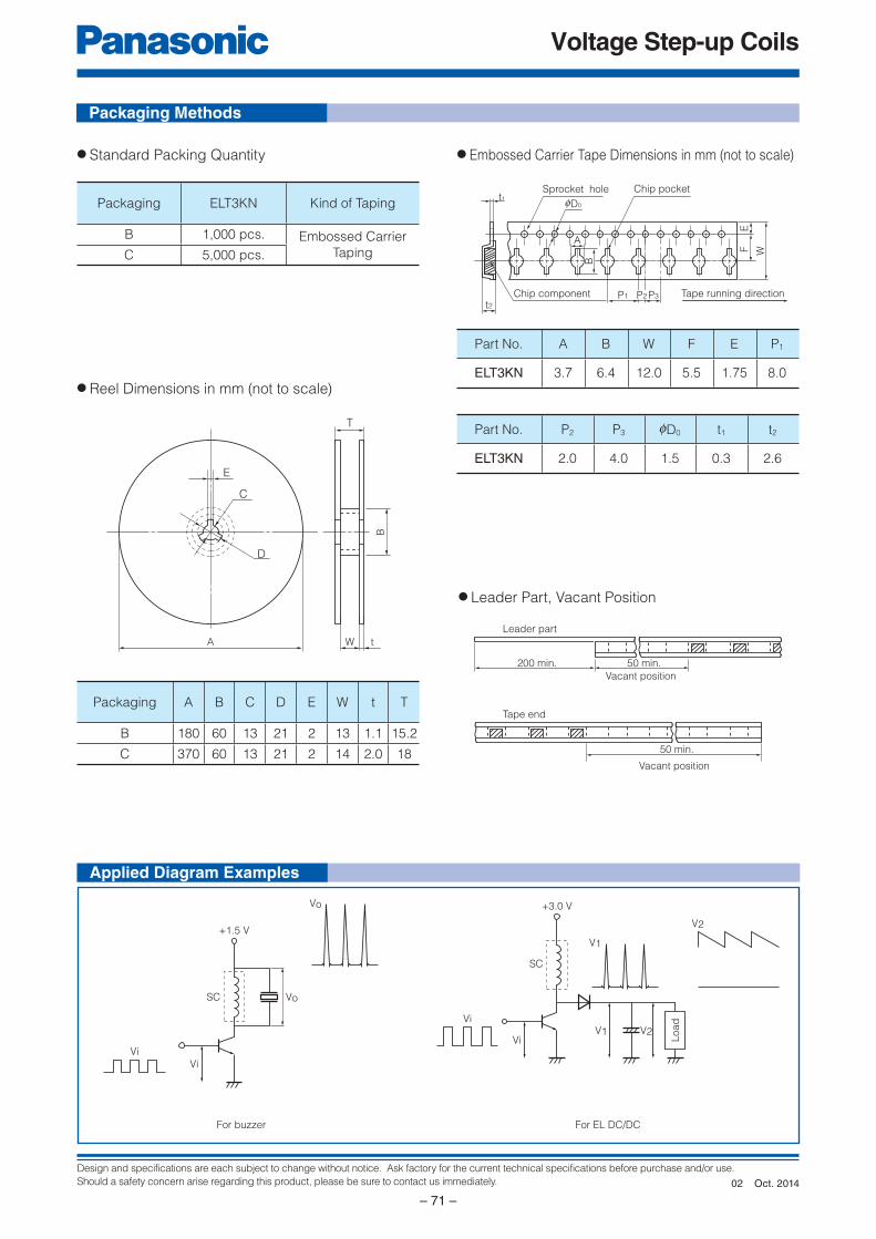
Design and specifications are each subject to change without notice. Ask factory for the current technical specifications before purchase and/or use.
Should a safety concern arise regarding this product, please be sure to contact us immediately.
Voltage Step-up Coils
– 71 –
t1
t2Chip component P1 P3
Chip pocket
Tape running direction
EF
W
Sprocket hole
A
B
fD0
P2
T
C
E
D
B
W tA
200 min. 50 min.
Leader part
Tape end
50 min.
Vacant position
Vacant position
Vi
Vi
SC Vo
Vo
+1.5 V
For buzzer
Vi
ViV1 V2
SC
V1
V2
+3.0 V
Load
For EL DC/DC
Packaging Methods
Applied Diagram Examples
● Standard Packing Quantity ● Embossed Carrier Tape Dimensions in mm (not to scale)
● Reel Dimensions in mm (not to scale)
● Leader Part, Vacant Position
Packaging ELT3KN Kind of Taping
B 1,000 pcs. Embossed Carrier
TapingC 5,000 pcs.
Part No. A B W F E P1
ELT3KN 3.7 6.4 12.0 5.5 1.75 8.0
Part No. P2 P3 0D0 t1 t2
ELT3KN 2.0 4.0 1.5 0.3 2.6
Packaging A B C D E W t T
B 180 60 13 21 2 13 1.1 15.2
C 370 60 13 21 2 14 2.0 18
Oct. 201402
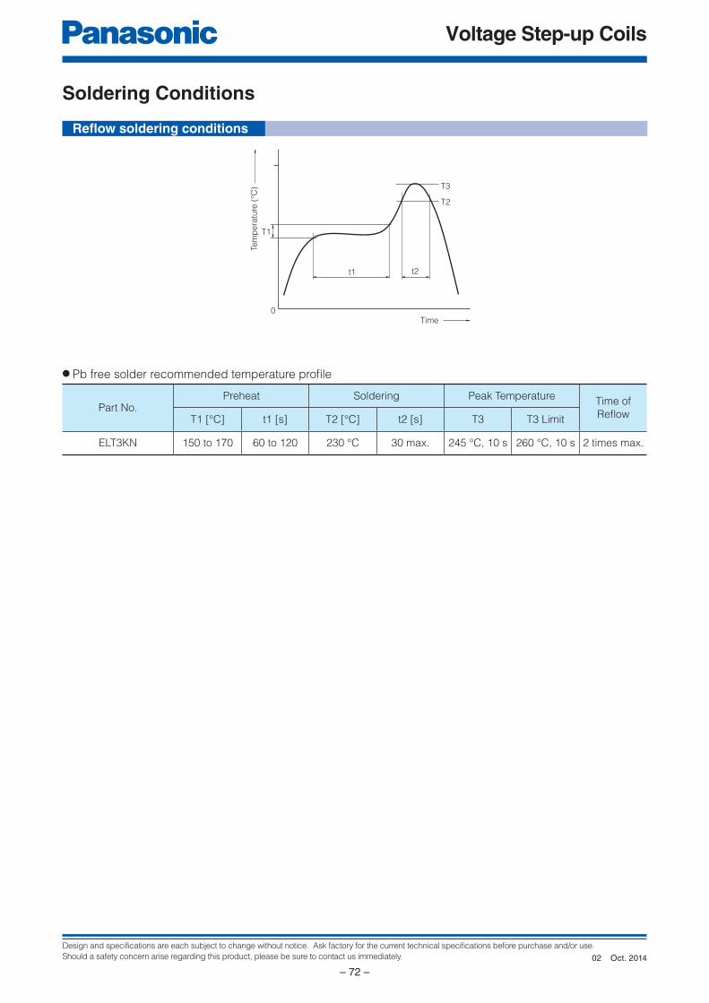
Design and specifications are each subject to change without notice. Ask factory for the current technical specifications before purchase and/or use.
Should a safety concern arise regarding this product, please be sure to contact us immediately.
Voltage Step-up Coils
– 72 –
t2
Tem
pe
ratu
re (
°C)
Time
T3
T2
T1
t1
0
Refl ow soldering conditions
Soldering Conditions
● Pb free solder recommended temperature profi le
Part No.Preheat Soldering Peak Temperature
Time of
Refl owT1 [°C] t1 [s] T2 [°C] t2 [s] T3 T3 Limit
ELT3KN 150 to 170 60 to 120 230 °C 30 max. 245 °C, 10 s 260 °C, 10 s 2 times max.
Oct. 201402
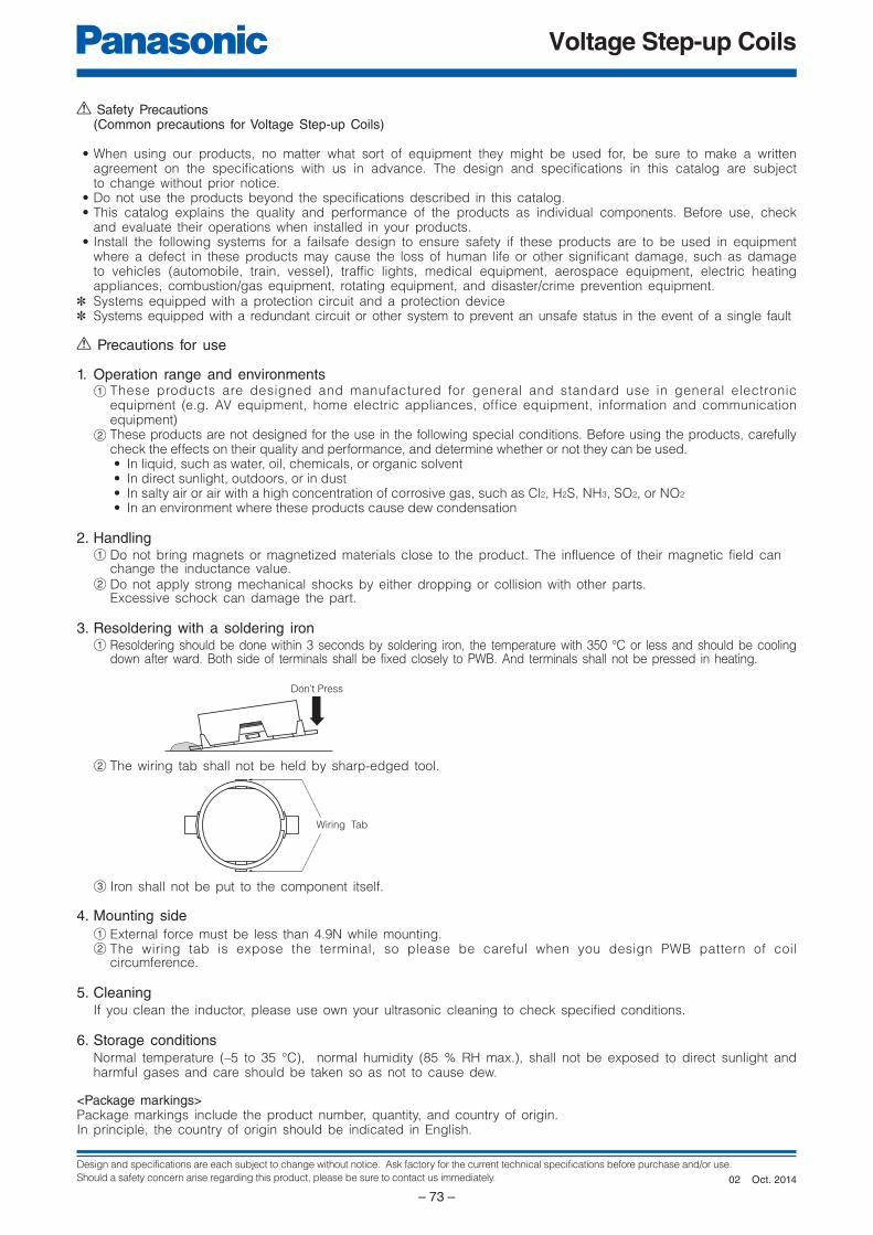
Design and specifications are each subject to change without notice. Ask factory for the current technical specifications before purchase and/or use.
Should a safety concern arise regarding this product, please be sure to contact us immediately.
Voltage Step-up Coils
– 73 –
Don’t Press
Wiring Tab
Precautions for use
1. Operation range and environments1 These products are designed and manufactured for general and stan dard use in general elec tron ic
equipment (e.g. AV equipment, home electric ap pli anc es, office equipment, information and com mu ni ca tionequipment)
2 These products are not designed for the use in the following special conditions. Be fore using the products, care ful ly check the effects on their quality and performance, and determine whether or not they can be used. • In liquid, such as water, oil, chemicals, or organic solvent • In direct sunlight, outdoors, or in dust • In salty air or air with a high concentration of corrosive gas, such as Cl2, H2S, NH3, SO2, or NO2
• In an environment where these products cause dew condensation
2. Handling1 Do not bring magnets or magnetized materials close to the product. The influence of their magnetic field can change the inductance value.2 Do not apply strong mechanical shocks by either dropping or collision with other parts. Excessive schock can damage the part.
3. Resoldering with a soldering iron1 Resoldering should be done within 3 seconds by soldering iron, the temperature with 350 °C or less and should be cooling
down after ward. Both side of terminals shall be fixed closely to PWB. And terminals shall not be pressed in heating.
Safety Precautions (Common precautions for Voltage Step-up Coils)
• When using our products, no matter what sort of equipment they might be used for, be sure to make a written agreement on the specifications with us in advance. The design and specifications in this catalog are subjectto change without prior notice.
• Do not use the products beyond the specifications described in this catalog. • This catalog explains the quality and performance of the products as individual components. Be fore use, check
and evaluate their operations when installed in your products. • Install the following systems for a failsafe design to ensure safety if these products are to be used in equip ment
where a defect in these products may cause the loss of human life or other significant damage, such as damage to vehicles (au to mo bile, train, vessel), traffic lights, medical equipment, aerospace equipment, elec tric heatingap pli anc es, com bus tion/gas equipment, rotating equipment, and disaster/crime prevention equip ment.
✽ Systems equipped with a protection circuit and a protection device✽ Systems equipped with a redundant circuit or other system to prevent an unsafe status in the event of a single fault
<Package markings>Package markings include the product number, quantity, and country of origin.In principle, the country of origin should be indicated in English.
2 The wiring tab shall not be held by sharp-edged tool.
3 Iron shall not be put to the component itself.
4. Mounting side
1 External force must be less than 4.9N while mounting.2 The wiring tab is expose the terminal, so please be careful when you design PWB pattern of coil
circumference.
5. CleaningIf you clean the inductor, please use own your ultrasonic cleaning to check specified conditions.
6. Storage conditionsNormal temperature (–5 to 35 °C), normal humidity (85 % RH max.), shall not be exposed to direct sunlight and harmful gases and care should be taken so as not to cause dew.
Oct. 201402

Design and specifications are each subject to change without notice. Ask factory for the current technical specifications before purchase and/or use.
Should a safety concern arise regarding this product, please be sure to contact us immediately.
Power Inductors
– 74 –
E
1
L
2
C
3
0
4
9
5
D
6
2
7
R
8
2
9 1110
Product code Style Construction Inductance Packaging
Core size
Terminal board
or
Case size
Core CoreCase
Terminal Terminal
Core
Core
Terminal board
Terminal
Core (Magnetic Shielded)
Terminal board
Terminal
Taping
Other
D
Omission
E, F etc.
✽
✽
D
B
E
P
09
11
12
15
16
18
Direct terminal by wire
Design No.
10000
L (µH)
10 50 100 500 1000 5000 10000
IDC(mA)
5000
1000
500
100
50
10
5
1
09D 16B 18B
10000
L (µH)
5000
1000
500
100
50
10
5
110 50 100 500 1000 5000 10000
IDC(mA)
10E 12E15E 18E
Explanation of Part Numbers
Features
Choke Coils
Series : Pin terminalType : 09D, 11D, 12D, 16B, 18B, 10E, 12E, 15E, 18E
● Appliance, Offi ce automation equipment,
Amusement machine, Power circuit for electric
device
● High - µ and High Bm cores● Wide inductor range● Magnetic shield type (E Type)● RoHS compliant
Pin terminal inductors featuring small size and high performance
Type 09D Type 11D Type 12D
Type 16B Type 18B Type 10E–L
Type 12E–L Type 15E–L Type 18E–L
Recommended Applications
Available I-L Characteristics
Oct. 201402

Design and specifications are each subject to change without notice. Ask factory for the current technical specifications before purchase and/or use.
Should a safety concern arise regarding this product, please be sure to contact us immediately.
Power Inductors
– 75 –
Performance Characteristics by Series
Type ConstructionExtermal
DimensionsD×H (mm)
Inductance (µH) 0.1 1.0 10 100 1000 10000
Current
IDC (A)
Re
gu
lar
09D ✽ 09.5×8.9
(with case)0.08 to 3.5
11D ✽ 011.5×13.9
(with case)0.16 to 5.3
12D 012.5×16.5 0.27 to 1.9
16B 016.0×23.0 0.26 to 8.5
18B 020.0×27.0 0.36 to 8.5
Shie
ld
10E–L 010.0×13.0 0.10 to 2.9
12E–L 013.0×18.5 0.13 to 4.4
15E–L016.0×22.0
(3 pin terminal)0.30 to 5.4
18E–L019.0×25.1
(4 pin terminal)0.33 to 5.9
✽ : Taping Available
2.2 10000
2.2 10000
100 10000
3.3 10000
3.9 8200
4.7 10000
5.6 10000
5.6 10000
3.3 10000
Oct. 201402
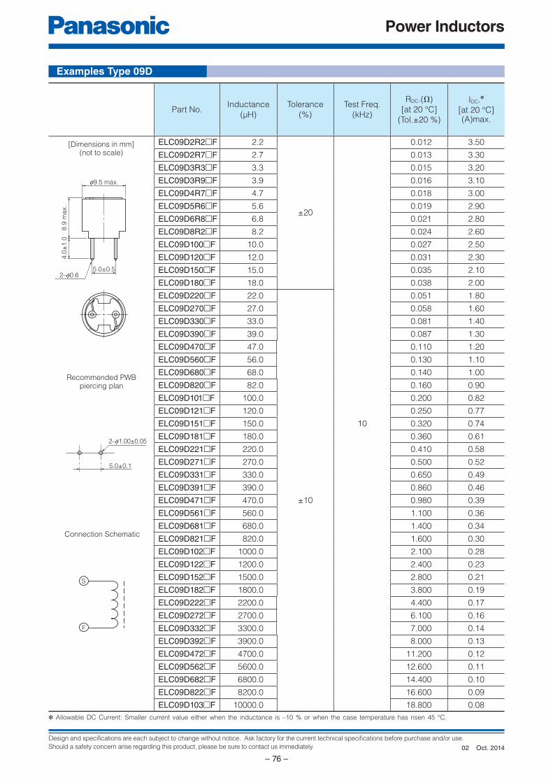
Design and specifications are each subject to change without notice. Ask factory for the current technical specifications before purchase and/or use.
Should a safety concern arise regarding this product, please be sure to contact us immediately.
Power Inductors
– 76 –
f9.5 max.
8.9
ma
x.
4.0
±1
.0
5.0±0.52–f0.6
5.0±0.1
2–f1.00±0.05
S
F
Examples Type 09D
Part No.Inductance
(µH)
Tolerance
(%)
Test Freq.
(kHz)
RDC.(Ω)
[at 20 °C]
(Tol.±20 %)
IDC.✽
[at 20 °C](A)max.
ELC09D2R2□F 2.2
±20
10
0.012 3.50
ELC09D2R7□F 2.7 0.013 3.30
ELC09D3R3□F 3.3 0.015 3.20
ELC09D3R9□F 3.9 0.016 3.10
ELC09D4R7□F 4.7 0.018 3.00
ELC09D5R6□F 5.6 0.019 2.90
ELC09D6R8□F 6.8 0.021 2.80
ELC09D8R2□F 8.2 0.024 2.60
ELC09D100□F 10.0 0.027 2.50
ELC09D120□F 12.0 0.031 2.30
ELC09D150□F 15.0 0.035 2.10
ELC09D180□F 18.0 0.038 2.00
ELC09D220□F 22.0
±10
0.051 1.80
ELC09D270□F 27.0 0.058 1.60
ELC09D330□F 33.0 0.081 1.40
ELC09D390□F 39.0 0.087 1.30
ELC09D470□F 47.0 0.110 1.20
ELC09D560□F 56.0 0.130 1.10
ELC09D680□F 68.0 0.140 1.00
ELC09D820□F 82.0 0.160 0.90
ELC09D101□F 100.0 0.200 0.82
ELC09D121□F 120.0 0.250 0.77
ELC09D151□F 150.0 0.320 0.74
ELC09D181□F 180.0 0.360 0.61
ELC09D221□F 220.0 0.410 0.58
ELC09D271□F 270.0 0.500 0.52
ELC09D331□F 330.0 0.650 0.49
ELC09D391□F 390.0 0.860 0.46
ELC09D471□F 470.0 0.980 0.39
ELC09D561□F 560.0 1.100 0.36
ELC09D681□F 680.0 1.400 0.34
ELC09D821□F 820.0 1.600 0.30
ELC09D102□F 1000.0 2.100 0.28
ELC09D122□F 1200.0 2.400 0.23
ELC09D152□F 1500.0 2.800 0.21
ELC09D182□F 1800.0 3.800 0.19
ELC09D222□F 2200.0 4.400 0.17
ELC09D272□F 2700.0 6.100 0.16
ELC09D332□F 3300.0 7.000 0.14
ELC09D392□F 3900.0 8.000 0.13
ELC09D472□F 4700.0 11.200 0.12
ELC09D562□F 5600.0 12.600 0.11
ELC09D682□F 6800.0 14.400 0.10
ELC09D822□F 8200.0 16.600 0.09
ELC09D103□F 10000.0 18.800 0.08
✽ Allowable DC Current: Smaller current value either when the inductance is –10 % or when the case temperature has risen 45 °C.
[Dimensions in mm](not to scale)
Recommended PWBpiercing plan
Connection Schematic
Oct. 201402
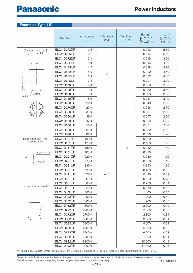
Design and specifications are each subject to change without notice. Ask factory for the current technical specifications before purchase and/or use.
Should a safety concern arise regarding this product, please be sure to contact us immediately.
Power Inductors
– 77 –
f11.5 max.
13
.9 m
ax.
4.0
±1
.0
5.0±0.52–f0.6
5.0±0.1
2–f1.00±0.05
S
F
Part No.Inductance
(µH)
Tolerance
(%)
Test Freq.
(kHz)
R.DC.(Ω)
[at 20 °C]
(Tol.±20 %)
IDC.✽
[at 20 °C](A)max.
ELC11D2R2□F 2.2
±20
10
0.013 5.30
ELC11D2R7□F 2.7 0.014 5.10
ELC11D3R3□F 3.3 0.015 4.90
ELC11D3R9□F 3.9 0.016 4.80
ELC11D4R7□F 4.7 0.018 4.70
ELC11D5R6□F 5.6 0.020 4.60
ELC11D6R8□F 6.8 0.022 4.40
ELC11D8R2□F 8.2 0.024 3.90
ELC11D100□F 10.0 0.029 3.50
ELC11D120□F 12.0 0.030 3.40
ELC11D150□F 15.0 0.033 3.30
ELC11D180□F 18.0 0.037 3.10
ELC11D220□F 22.0
±10
0.040 2.80
ELC11D270□F 27.0 0.048 2.70
ELC11D330□F 33.0 0.051 2.60
ELC11D390□F 39.0 0.057 2.50
ELC11D470□F 47.0 0.063 2.30
ELC11D560□F 56.0 0.071 2.10
ELC11D680□F 68.0 0.082 2.00
ELC11D820□F 82.0 0.090 1.90
ELC11D101□F 100.0 0.120 1.80
ELC11D121□F 120.0 0.160 1.60
ELC11D151□F 150.0 0.180 1.40
ELC11D181□F 180.0 0.200 1.30
ELC11D221□F 220.0 0.230 1.20
ELC11D271□F 270.0 0.320 1.10
ELC11D331□F 330.0 0.350 1.00
ELC11D391□F 390.0 0.400 0.95
ELC11D471□F 470.0 0.490 0.82
ELC11D561□F 560.0 0.620 0.73
ELC11D681□F 680.0 0.780 0.64
ELC11D821□F 820.0 0.870 0.62
ELC11D102□F 1000.0 1.100 0.57
ELC11D122□F 1200.0 1.200 0.52
ELC11D152□F 1500.0 1.700 0.43
ELC11D182□F 1800.0 2.000 0.40
ELC11D222□F 2200.0 2.300 0.38
ELC11D272□F 2700.0 2.800 0.34
ELC11D332□F 3300.0 3.600 0.31
ELC11D392□F 3900.0 4.500 0.29
ELC11D472□F 4700.0 5.200 0.26
ELC11D562□F 5600.0 6.900 0.23
ELC11D682□F 6800.0 7.800 0.21
ELC11D822□F 8200.0 10.600 0.18
ELC11D103□F 10000.0 11.800 0.16
Recommended PWBpiercing plan
Connection Schematic
[Dimensions in mm](not to scale)
✽ Allowable DC Current: Smaller current value either when the inductance is –10 % or when the case temperature has risen 45 °C.
Examples Type 11D
Oct. 201402
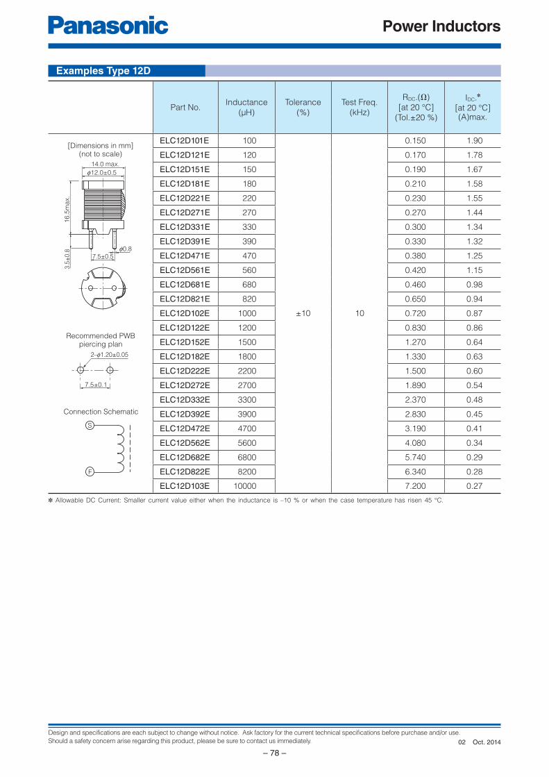
Design and specifications are each subject to change without notice. Ask factory for the current technical specifications before purchase and/or use.
Should a safety concern arise regarding this product, please be sure to contact us immediately.
Power Inductors
– 78 –
f0.87.5±0.5
16
.5m
ax.
3.5
±0.8
14.0 max.
f12.0±0.5
7.5±0.1
2–f1.20±0.05
S
F
Examples Type 12D
Part No.Inductance
(µH)
Tolerance
(%)
Test Freq.
(kHz)
RDC.(Ω)
[at 20 °C]
(Tol.±20 %)
IDC.✽
[at 20 °C](A)max.
ELC12D101E 100
±10 10
0.150 1.90
ELC12D121E 120 0.170 1.78
ELC12D151E 150 0.190 1.67
ELC12D181E 180 0.210 1.58
ELC12D221E 220 0.230 1.55
ELC12D271E 270 0.270 1.44
ELC12D331E 330 0.300 1.34
ELC12D391E 390 0.330 1.32
ELC12D471E 470 0.380 1.25
ELC12D561E 560 0.420 1.15
ELC12D681E 680 0.460 0.98
ELC12D821E 820 0.650 0.94
ELC12D102E 1000 0.720 0.87
ELC12D122E 1200 0.830 0.86
ELC12D152E 1500 1.270 0.64
ELC12D182E 1800 1.330 0.63
ELC12D222E 2200 1.500 0.60
ELC12D272E 2700 1.890 0.54
ELC12D332E 3300 2.370 0.48
ELC12D392E 3900 2.830 0.45
ELC12D472E 4700 3.190 0.41
ELC12D562E 5600 4.080 0.34
ELC12D682E 6800 5.740 0.29
ELC12D822E 8200 6.340 0.28
ELC12D103E 10000 7.200 0.27
[Dimensions in mm](not to scale)
Recommended PWBpiercing plan
Connection Schematic
✽ Allowable DC Current: Smaller current value either when the inductance is –10 % or when the case temperature has risen 45 °C.
Oct. 201402
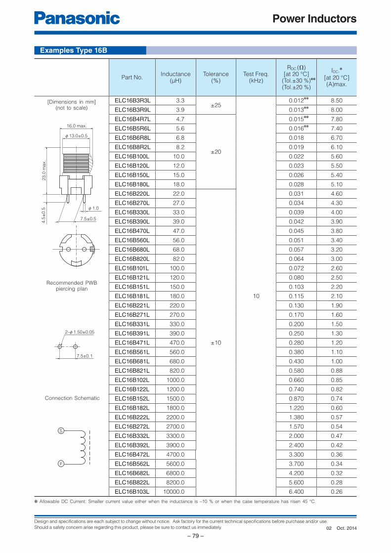
Design and specifications are each subject to change without notice. Ask factory for the current technical specifications before purchase and/or use.
Should a safety concern arise regarding this product, please be sure to contact us immediately.
Power Inductors
– 79 –
7.5±0.5
f 1.0
4.5
±0
.52
3.0
ma
x.
f 13.0±0.5
16.0 max.
2–f 1.50±0.05
7.5±0.1
S
F
[Dimensions in mm](not to scale)
Recommended PWBpiercing plan
Connection Schematic
Part No.Inductance
(µH)Tolerance
(%)Test Freq.
(kHz)
RDC.(Ω)[at 20 °C]
(Tol.±30 %)✽✽
(Tol.±20 %)
IDC.✽
[at 20 °C](A)max.
ELC16B3R3L 3.3±25
10
0.012✽✽
8.50
ELC16B3R9L 3.9 0.013✽✽
8.00
ELC16B4R7L 4.7
±20
0.015✽✽
7.80
ELC16B5R6L 5.6 0.016✽✽
7.40
ELC16B6R8L 6.8 0.018 6.70
ELC16B8R2L 8.2 0.019 6.10
ELC16B100L 10.0 0.022 5.60
ELC16B120L 12.0 0.023 5.50
ELC16B150L 15.0 0.026 5.40
ELC16B180L 18.0 0.028 5.10
ELC16B220L 22.0
±10
0.031 4.60
ELC16B270L 27.0 0.034 4.30
ELC16B330L 33.0 0.039 4.00
ELC16B390L 39.0 0.042 3.90
ELC16B470L 47.0 0.045 3.80
ELC16B560L 56.0 0.051 3.40
ELC16B680L 68.0 0.057 3.20
ELC16B820L 82.0 0.064 3.00
ELC16B101L 100.0 0.072 2.60
ELC16B121L 120.0 0.080 2.50
ELC16B151L 150.0 0.103 2.20
ELC16B181L 180.0 0.115 2.10
ELC16B221L 220.0 0.130 1.90
ELC16B271L 270.0 0.170 1.60
ELC16B331L 330.0 0.200 1.50
ELC16B391L 390.0 0.250 1.30
ELC16B471L 470.0 0.280 1.20
ELC16B561L 560.0 0.380 1.10
ELC16B681L 680.0 0.430 1.00
ELC16B821L 820.0 0.580 0.88
ELC16B102L 1000.0 0.660 0.85
ELC16B122L 1200.0 0.740 0.82
ELC16B152L 1500.0 0.870 0.74
ELC16B182L 1800.0 1.220 0.60
ELC16B222L 2200.0 1.380 0.57
ELC16B272L 2700.0 1.570 0.54
ELC16B332L 3300.0 2.000 0.47
ELC16B392L 3900.0 2.400 0.42
ELC16B472L 4700.0 3.300 0.36
ELC16B562L 5600.0 3.700 0.34
ELC16B682L 6800.0 4.200 0.32
ELC16B822L 8200.0 5.600 0.28
ELC16B103L 10000.0 6.400 0.26
✽ Allowable DC Current: Smaller current value either when the inductance is –10 % or when the case temperature has risen 45 °C.
Examples Type 16B
Oct. 201402
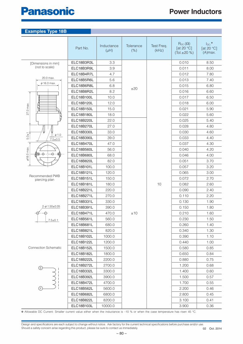
Design and specifications are each subject to change without notice. Ask factory for the current technical specifications before purchase and/or use.
Should a safety concern arise regarding this product, please be sure to contact us immediately.
Power Inductors
– 80 –
f18.0
max.
f 16.0 max.
20.0 max.
5.0
±1
27
.0 m
ax.
f 1.0
7.5±0.5
7.5±0.1
2–f 1.50±0.05
S
F
✽ Allowable DC Current: Smaller current value either when the inductance is –10 % or when the case temperature has risen 45 °C.
Part No.Inductance
(µH)
Tolerance
(%)
Test Freq.
(kHz)
RDC.(Ω)
[at 20 °C]
(Tol.±20 %)
IDC.✽
[at 20 °C](A)max.
ELC18B3R3L 3.3
±20
10
0.010 8.50
ELC18B3R9L 3.9 0.011 8.00
ELC18B4R7L 4.7 0.012 7.80
ELC18B5R6L 5.6 0.013 7.40
ELC18B6R8L 6.8 0.015 6.80
ELC18B8R2L 8.2 0.016 6.60
ELC18B100L 10.0 0.017 6.50
ELC18B120L 12.0 0.018 6.00
ELC18B150L 15.0 0.021 5.90
ELC18B180L 18.0 0.022 5.60
ELC18B220L 22.0
±10
0.025 5.40
ELC18B270L 27.0 0.028 4.80
ELC18B330L 33.0 0.030 4.60
ELC18B390L 39.0 0.033 4.40
ELC18B470L 47.0 0.037 4.30
ELC18B560L 56.0 0.040 4.20
ELC18B680L 68.0 0.046 4.00
ELC18B820L 82.0 0.051 3.70
ELC18B101L 100.0 0.057 3.20
ELC18B121L 120.0 0.065 3.00
ELC18B151L 150.0 0.072 2.70
ELC18B181L 180.0 0.082 2.60
ELC18B221L 220.0 0.090 2.40
ELC18B271L 270.0 0.110 2.20
ELC18B331L 330.0 0.130 1.90
ELC18B391L 390.0 0.150 1.80
ELC18B471L 470.0 0.210 1.60
ELC18B561L 560.0 0.230 1.50
ELC18B681L 680.0 0.260 1.40
ELC18B821L 820.0 0.340 1.30
ELC18B102L 1000.0 0.390 1.10
ELC18B122L 1200.0 0.440 1.00
ELC18B152L 1500.0 0.580 0.85
ELC18B182L 1800.0 0.650 0.84
ELC18B222L 2200.0 0.880 0.75
ELC18B272L 2700.0 1.200 0.68
ELC18B332L 3300.0 1.400 0.60
ELC18B392L 3900.0 1.500 0.57
ELC18B472L 4700.0 1.700 0.55
ELC18B562L 5600.0 2.200 0.46
ELC18B682L 6800.0 2.800 0.45
ELC18B822L 8200.0 3.100 0.41
ELC18B103L 10000.0 3.900 0.36
[Dimensions in mm](not to scale)
Recommended PWBpiercing plan
Connection Schematic
Examples Type 18B
Oct. 201402
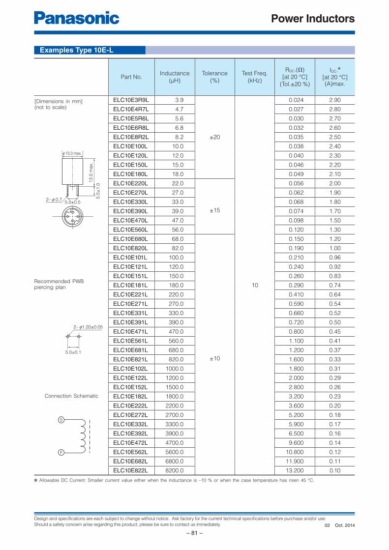
Design and specifications are each subject to change without notice. Ask factory for the current technical specifications before purchase and/or use.
Should a safety concern arise regarding this product, please be sure to contact us immediately.
Power Inductors
– 81 –
5.0
±1
.0
13
.0 m
ax.
f 10.0 max.
5.0±0.52– f 0.7
2– f1.20±0.05
5.0±0.1
S
F
Examples Type 10E-L
✽ Allowable DC Current: Smaller current value either when the inductance is –10 % or when the case temperature has risen 45 °C.
[Dimensions in mm](not to scale)
Recommended PWBpiercing plan
Connection Schematic
Part No.Inductance
(µH)
Tolerance
(%)
Test Freq.
(kHz)
RDC.(Ω)
[at 20 °C]
(Tol.±20 %)
IDC.✽
[at 20 °C](A)max.
ELC10E3R9L 3.9
±20
10
0.024 2.90
ELC10E4R7L 4.7 0.027 2.80
ELC10E5R6L 5.6 0.030 2.70
ELC10E6R8L 6.8 0.032 2.60
ELC10E8R2L 8.2 0.035 2.50
ELC10E100L 10.0 0.038 2.40
ELC10E120L 12.0 0.040 2.30
ELC10E150L 15.0 0.046 2.20
ELC10E180L 18.0 0.049 2.10
ELC10E220L 22.0
±15
0.056 2.00
ELC10E270L 27.0 0.062 1.90
ELC10E330L 33.0 0.068 1.80
ELC10E390L 39.0 0.074 1.70
ELC10E470L 47.0 0.098 1.50
ELC10E560L 56.0 0.120 1.30
ELC10E680L 68.0
±10
0.150 1.20
ELC10E820L 82.0 0.190 1.00
ELC10E101L 100.0 0.210 0.96
ELC10E121L 120.0 0.240 0.92
ELC10E151L 150.0 0.260 0.83
ELC10E181L 180.0 0.290 0.74
ELC10E221L 220.0 0.410 0.64
ELC10E271L 270.0 0.590 0.54
ELC10E331L 330.0 0.660 0.52
ELC10E391L 390.0 0.720 0.50
ELC10E471L 470.0 0.800 0.45
ELC10E561L 560.0 1.100 0.41
ELC10E681L 680.0 1.200 0.37
ELC10E821L 820.0 1.600 0.33
ELC10E102L 1000.0 1.800 0.31
ELC10E122L 1200.0 2.000 0.29
ELC10E152L 1500.0 2.800 0.26
ELC10E182L 1800.0 3.200 0.23
ELC10E222L 2200.0 3.600 0.20
ELC10E272L 2700.0 5.200 0.18
ELC10E332L 3300.0 5.900 0.17
ELC10E392L 3900.0 6.500 0.16
ELC10E472L 4700.0 9.600 0.14
ELC10E562L 5600.0 10.800 0.12
ELC10E682L 6800.0 11.900 0.11
ELC10E822L 8200.0 13.200 0.10
Oct. 201402
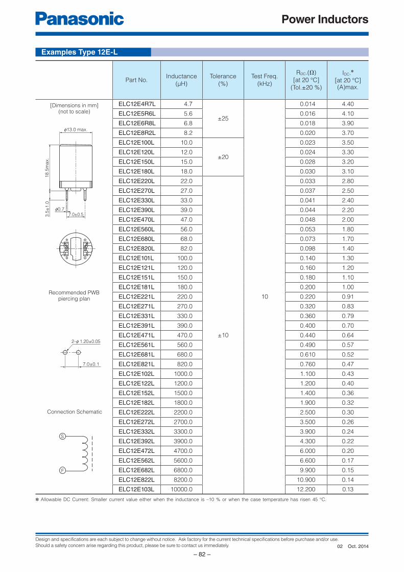
Design and specifications are each subject to change without notice. Ask factory for the current technical specifications before purchase and/or use.
Should a safety concern arise regarding this product, please be sure to contact us immediately.
Power Inductors
– 82 –
S
F
18
.5m
ax.
f0.77.0±0.53
.5±
1.0
f13.0 max.
7.0±0.1
2–f 1.20±0.05
Examples Type 12E-L
✽ Allowable DC Current: Smaller current value either when the inductance is –10 % or when the case temperature has risen 45 °C.
[Dimensions in mm](not to scale)
Recommended PWBpiercing plan
Connection Schematic
Part No.Inductance
(µH)
Tolerance
(%)
Test Freq.
(kHz)
RDC.(Ω)
[at 20 °C]
(Tol.±20 %)
IDC.✽
[at 20 °C](A)max.
ELC12E4R7L 4.7
±25
10
0.014 4.40
ELC12E5R6L 5.6 0.016 4.10
ELC12E6R8L 6.8 0.018 3.90
ELC12E8R2L 8.2 0.020 3.70
ELC12E100L 10.0
±20
0.023 3.50
ELC12E120L 12.0 0.024 3.30
ELC12E150L 15.0 0.028 3.20
ELC12E180L 18.0 0.030 3.10
ELC12E220L 22.0
±10
0.033 2.80
ELC12E270L 27.0 0.037 2.50
ELC12E330L 33.0 0.041 2.40
ELC12E390L 39.0 0.044 2.20
ELC12E470L 47.0 0.048 2.00
ELC12E560L 56.0 0.053 1.80
ELC12E680L 68.0 0.073 1.70
ELC12E820L 82.0 0.098 1.40
ELC12E101L 100.0 0.140 1.30
ELC12E121L 120.0 0.160 1.20
ELC12E151L 150.0 0.180 1.10
ELC12E181L 180.0 0.200 1.00
ELC12E221L 220.0 0.220 0.91
ELC12E271L 270.0 0.320 0.83
ELC12E331L 330.0 0.360 0.79
ELC12E391L 390.0 0.400 0.70
ELC12E471L 470.0 0.440 0.64
ELC12E561L 560.0 0.490 0.57
ELC12E681L 680.0 0.610 0.52
ELC12E821L 820.0 0.760 0.47
ELC12E102L 1000.0 1.100 0.43
ELC12E122L 1200.0 1.200 0.40
ELC12E152L 1500.0 1.400 0.36
ELC12E182L 1800.0 1.900 0.32
ELC12E222L 2200.0 2.500 0.30
ELC12E272L 2700.0 3.500 0.26
ELC12E332L 3300.0 3.900 0.24
ELC12E392L 3900.0 4.300 0.22
ELC12E472L 4700.0 6.000 0.20
ELC12E562L 5600.0 6.600 0.17
ELC12E682L 6800.0 9.900 0.15
ELC12E822L 8200.0 10.900 0.14
ELC12E103L 10000.0 12.200 0.13
Oct. 201402
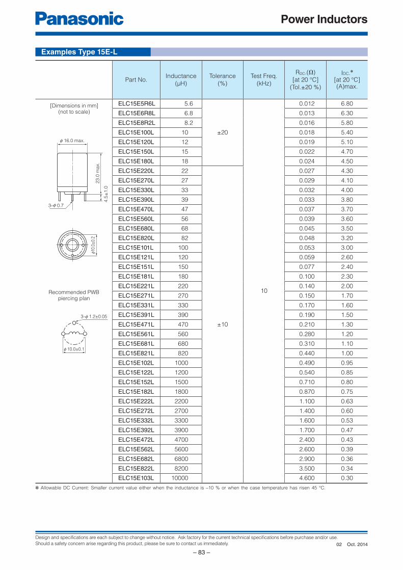
Design and specifications are each subject to change without notice. Ask factory for the current technical specifications before purchase and/or use.
Should a safety concern arise regarding this product, please be sure to contact us immediately.
Power Inductors
– 83 –
4.5
±1
.0
23
.0 m
ax.
f 16.0 max.
3–f 0.7
f10.
0±0.
2
3–f 1.2±0.05
f 10.0±0.1
Examples Type 15E-L
Part No.Inductance
(µH)
Tolerance
(%)
Test Freq.
(kHz)
RDC.(Ω)
[at 20 °C]
(Tol.±20 %)
IDC.✽
[at 20 °C](A)max.
ELC15E5R6L 5.6
±20
10
0.012 6.80
ELC15E6R8L 6.8 0.013 6.30
ELC15E8R2L 8.2 0.016 5.80
ELC15E100L 10 0.018 5.40
ELC15E120L 12 0.019 5.10
ELC15E150L 15 0.022 4.70
ELC15E180L 18 0.024 4.50
ELC15E220L 22
±10
0.027 4.30
ELC15E270L 27 0.029 4.10
ELC15E330L 33 0.032 4.00
ELC15E390L 39 0.033 3.80
ELC15E470L 47 0.037 3.70
ELC15E560L 56 0.039 3.60
ELC15E680L 68 0.045 3.50
ELC15E820L 82 0.048 3.20
ELC15E101L 100 0.053 3.00
ELC15E121L 120 0.059 2.60
ELC15E151L 150 0.077 2.40
ELC15E181L 180 0.100 2.30
ELC15E221L 220 0.140 2.00
ELC15E271L 270 0.150 1.70
ELC15E331L 330 0.170 1.60
ELC15E391L 390 0.190 1.50
ELC15E471L 470 0.210 1.30
ELC15E561L 560 0.280 1.20
ELC15E681L 680 0.310 1.10
ELC15E821L 820 0.440 1.00
ELC15E102L 1000 0.490 0.95
ELC15E122L 1200 0.540 0.85
ELC15E152L 1500 0.710 0.80
ELC15E182L 1800 0.870 0.75
ELC15E222L 2200 1.100 0.63
ELC15E272L 2700 1.400 0.60
ELC15E332L 3300 1.600 0.53
ELC15E392L 3900 1.700 0.47
ELC15E472L 4700 2.400 0.43
ELC15E562L 5600 2.600 0.39
ELC15E682L 6800 2.900 0.36
ELC15E822L 8200 3.500 0.34
ELC15E103L 10000 4.600 0.30
✽ Allowable DC Current: Smaller current value either when the inductance is –10 % or when the case temperature has risen 45 °C.
[Dimensions in mm](not to scale)
Recommended PWBpiercing plan
Oct. 201402

Design and specifications are each subject to change without notice. Ask factory for the current technical specifications before purchase and/or use.
Should a safety concern arise regarding this product, please be sure to contact us immediately.
Power Inductors
– 84 –
25
.0 m
ax.
f 19.0 max.
11.3±0.54–f 0.8
8.3
±0.5
3.5±
1.0
4–f 1.2±0.05
11.3±0.1
8.3
±0.1
Examples Type 18E-L
(Top View)
Part No.Inductance
(µH)
Tolerance
(%)
Test Freq.
(kHz)
RDC.(Ω)
[at 20 °C]
(Tol.±20 %)
IDC.✽
[at 20 °C](A)max.
ELC18E5R6L 5.6
±20
10
0.011 6.70
ELC18E6R8L 6.8 0.013 6.50
ELC18E8R2L 8.2 0.013 6.20
ELC18E100L 10 0.014 5.90
ELC18E120L 12 0.016 5.60
ELC18E150L 15 0.017 5.40
ELC18E180L 18 0.019 5.20
ELC18E220L 22
±10
0.022 5.00
ELC18E270L 27 0.023 4.80
ELC18E330L 33 0.026 4.60
ELC18E390L 39 0.028 4.50
ELC18E470L 47 0.030 4.10
ELC18E560L 56 0.031 3.80
ELC18E680L 68 0.036 3.60
ELC18E820L 82 0.040 3.50
ELC18E101L 100 0.044 3.00
ELC18E121L 120 0.047 2.80
ELC18E151L 150 0.061 2.60
ELC18E181L 180 0.067 2.50
ELC18E221L 220 0.076 2.10
ELC18E271L 270 0.083 2.00
ELC18E331L 330 0.110 1.90
ELC18E391L 390 0.120 1.80
ELC18E471L 470 0.150 1.50
ELC18E561L 560 0.170 1.40
ELC18E681L 680 0.190 1.20
ELC18E821L 820 0.210 1.10
ELC18E102L 1000 0.280 1.00
ELC18E122L 1200 0.360 0.95
ELC18E152L 1500 0.510 0.90
ELC18E182L 1800 0.570 0.80
ELC18E222L 2200 0.630 0.73
ELC18E272L 2700 0.890 0.65
ELC18E332L 3300 1.000 0.60
ELC18E392L 3900 1.100 0.50
ELC18E472L 4700 1.400 0.48
ELC18E562L 5600 1.600 0.46
ELC18E682L 6800 2.200 0.39
ELC18E822L 8200 2.400 0.35
ELC18E103L 10000 2.700 0.33
✽ Allowable DC Current: Smaller current value either when the inductance is –10 % or when the case temperature has risen 45 °C.
[Dimensions in mm](not to scale)
Recommended PWBpiercing plan
Oct. 201402
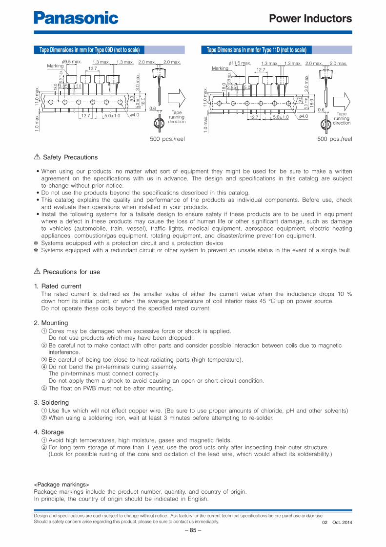
Design and specifications are each subject to change without notice. Ask factory for the current technical specifications before purchase and/or use.
Should a safety concern arise regarding this product, please be sure to contact us immediately.
Power Inductors
– 85 –
Taperunningdirection
Markingf9.5 max.
f4.0
0.6
1.3 max. 1.3 max. 2.0 max.2.0 max.
12.7
12.7 5.0±1.0
3.85 5.0
8.9
max
.
9.0
18
.0
5.0
min
.3
.0 m
ax.
11
.0 m
ax.
1.0
ma
x.
18.0
Taperunningdirection
Markingf11.5 max.
f4.0
0.6
1.3 max. 1.3 max. 2.0 max.2.0 max.
12.7
12.7 5.0±1.0
3.85 5.0
13.9
max
.
9.0
18
.0
5.0
min
.3
.0 m
ax.
11
.0 m
ax.
1.0
ma
x.
18
.0
500 pcs./reel 500 pcs./reel
Precautions for use
1. Rated currentThe rated current is defined as the smaller value of ei ther the current value when the inductance drops 10 %
down from its initial point, or when the average temperature of coil interior rises 45 °C up on pow er source.
Do not operate these coils beyond the specified rat ed current.
2. Mounting
1 Cores may be damaged when ex ces sive force or shock is applied. Do not use products which may have been dropped.
2 Be careful not to make contact with other parts and consider possible interaction between coils due to magnetic interference.
3 Be careful of being too close to heat-radiating parts (high temperature).
4 Do not bend the pin-terminals during assembly. The pin-terminals must connect correctly.
Do not apply them a shock to avoid causing an open or short circuit condition.
5 The float on PWB must not be after mounting.
3. Soldering
1 Use flux which will not effect copper wire. (Be sure to use proper amounts of chloride, pH and other solvents)
2 When using a soldering iron, wait at least 3 minutes before attempting to re-solder.
4. Storage
1 Avoid high temperatures, high moisture, gases and magnetic fields.
2 For long term storage of more than 1 year, use the prod ucts only after inspecting their outer structure. (Look for possible rusting of the core and oxidation of the lead wire, which would affect its solderability.)
Safety Precautions
• When using our products, no matter what sort of equipment they might be used for, be sure to make a written
agreement on the specifications with us in advance. The design and specifications in this catalog are subject
to change without prior notice.
• Do not use the products beyond the specifications described in this catalog.
• This catalog explains the quality and performance of the products as individual components. Be fore use, check
and evaluate their operations when installed in your products.
• Install the following systems for a failsafe design to ensure safety if these products are to be used in equip ment
where a defect in these products may cause the loss of human life or other significant damage, such as damage
to vehicles (au to mo bile, train, vessel), traffic lights, medical equipment, aerospace equipment, elec tric heating
ap pli anc es, com bus tion/gas equipment, rotating equipment, and disaster/crime prevention equip ment.
✽ Systems equipped with a protection circuit and a protection device
✽ Systems equipped with a redundant circuit or other system to prevent an unsafe status in the event of a single fault
<Package markings>
Package markings include the product number, quantity, and country of origin.
In principle, the country of origin should be indicated in English.
Tape Dimensions in mm for Type 09D (not to scale) Tape Dimensions in mm for Type 11D (not to scale)
Oct. 201402
● Please contact ● Factory
1. The electronic components contained in this catalog are designed and produced for use in home electric appliances, office equipment, information equipment, communications equipment, and other general purpose electronic devices.
Before use of any of these components for equipment that requires a high degree of safety, such as medical instruments, aerospace equipment, disaster-prevention equipment, security equipment, vehicles (automobile, train, vessel),
please be sure to contact our sales representative.2. When applying one of these components for equipment requiring a high degree of safety, no matter what sort of application it might be, be sure to install a protective
circuit or redundancy arrangement to enhance the safety of your equipment. In addition, please carry out the safety test on your own responsibility.3. When using our products, no matter what sort of equipment they might be used for, be sure to make a written agreement on the specifications with us in advance. 4. Technical information contained in this catalog is intended to convey examples of typical performances and/or applications and is not intended to make any
warranty with respect to the intellectual property rights or any other related rights of our company or any third parties nor grant any license under such rights. 5. In order to export products in this catalog, the exporter may be subject to the export license requirement under the Foreign Exchange and Foreign Trade Law of
Japan.6. No ozone-depleting substances (ODSs) under the Montreal Protocol are used in the manufacturing processes of Automotive & Industrial Systems Company, Panasonic
Corporation.
CAUTION AND WARNING
The information in this catalog is valid as of May 2015.
Device Solutions Business DivisionAutomotive & Industrial Systems Company Panasonic Corporation1006 Kadoma, Kadoma City, Osaka 571-8506, JAPAN