catalog 14c january 2013 - hubbellcdn.com · page 3 | january 2013 standard motor operators for...
TRANSCRIPT

Page 1 | January 2013
Catalog 14C January 2013
Page 2 | Janurary 2013
General DescriptionMotor Operators are electrically operated and have provisions for manual operation. A customer-supplied 120 Volt AC power source provides primary power to the motor and charges an internal battery. AC and battery power are supplied to the motor concurrently so that the motor operator will operate without hesitation regardless of whether the battery is weak or AC power is lost. If AC power is lost, the battery can provide more than 100 open/close operations. A power supply is provided to accommodate a remote terminal unit (RTU) and radio.
With the standard Motor Operator, for switches with down-the-pole controls, the motor and all operating controls are in an aluminum enclosure that easily mounts to the pole and the switch. Operators are available for switches with torsional or reciprocating operating mechanisms.
With the crossarm mounted Motor Operator, the motor is mounted on the crossarm and the controller (control electronics, battery, RTU, radio, etc.) is in a separate enclosure that mounts below the switch.
OperationMotor Operators can be operated locally or remotely. Local operation is available via an open/close switch, located on the front of the control panel. A remote/local selector switch is also located on the front of the control panel. Open/close status and local/remote status is reported through a status indicator.
Manual OperationAll motor operators are designed for manual operation. Manual operation interlocks are provided for operator safety.
Travel AdjustmentTravel adjustment for motor operators with down-the-pole controls is accomplished with auxiliary switches. Positioned for easy access, four auxiliary switch contacts are provided. Two are for limiting the shaft rotation and two are for status indication. No tools are required for adjusting the auxiliary switch cams.
For switches with reciprocating operation, the limit switches are factory preset. For switches with torsional operation, final open/close position adjustments are easily accomplished via the cams.
For crossarm-mounted operators, the open/close adjustment is set by the arm connecting the operator to the switch interphase shaft.
Heater and Thermostat ProtectionAll motor operator/control units are equipped with a thermostatically controlled 250 watt heater powered by the
120 volt AC source.
BatteryThe battery used is a single 12 Volt, 33 amp-hour lead acid type, completely sealed. A pressure relief valve opens only if there is excessive buildup of corrosive or explosive gas. Gases are vented outside the enclosure via a hose. There is a “battery manager” charging circuit with temperature compensation to help prevent overcharging or undercharging the battery.
The battery is monitored using a “smart” circuit. Automatically at 5-minute intervals, a 12-ampere load is applied to the battery and the battery voltage is measured with the battery charger off. If the battery test detects a drop below 12.1 Volts, a low voltage alarm is activated.
Status IndicationsSeveral status indications that can be reported back through the RTU include:
• Switch open/close position• Local/Remote status• Manual operation lockout status• Loss of AC voltage• Low battery voltage• No-Go status
These six statuses are indicated by LED’s on the control board within the operator. Other status indications are possible based on the capability of the RTU.
Additional FeaturesMotor operators incorporate additional features, including:
• Automatic Load Disconnect – drops all loads from battery power if AC power is lost for an extended period of time and the threshold is reached, preventing deep discharge of the battery which causes damage and unnecessary battery replacement.
• Stall-Out Timer with Auto-Reset – stops motor from trying to operate before the fuse is blown, if the motor is stalled (due to ice buildup, switch mechanical problems, etc.).
• No-Go Function – prevents the motor from trying to operate if the battery threshold for No-Go status is met, preventing underpowered or incomplete switch operation.
• Surge and Electrostatic Protection – All circuits have been tested to withstand surges and electrostatic voltages in accordance with ANSI C37.90.1 and C62.41 and MIL Std. DOC-HDBK263.
Options• Solar Panels for operation without external AC power.• 132 amp-hour capacity battery pack for solar application to extend operating capability in cloudy weather.• Factory installation and wiring of customer selected RT and radio.• Stainless steel enclosure instead of aluminum.• Sensor cable for connecting the motor operator to the AC power source and voltage and current sensors.• Battery cooler to extend battery life in hot weather.
ApplicationTo either automate an existing switch or to acquire a completely automated overhead switch to install, Chance offers solutions to your Distribution Automation requirements. We offer motor operators for both standard down-the-pole controls and crossarm mounting. They can be supplied as additions for existing switches or in an automated AR Switch package.
Motor Operatorfor Overhead Gang-Operated Distribution Switches
For detailed information on the AR Switch, refer to catalog section 14A.

Page 3 | January 2013
Standard Motor Operatorsfor Down-the-Pole Controls
• Reciprocating and torsional operator options for distribution and transmission applications
• Provision for installing an RTU and radio• Motor that runs on both AC and battery power for
double reliability• Status indications for switch position, charger, loss of
AC, battery condition• Vented 12 V, 33 A-H battery with temperature-
compensated charger• “Smart” battery load disconnect to help prevent
damage to the battery from deep discharge• “No Go” function with status indication to help prevent
underpowered switch operation• Effective surge protection• Easy retrofit to Chance AR and D7 switches as well as
overhead switches manufactured by others
Ordering Information
Complete automated switch package installations or add-on motor operators are based on factors including the application requirements, customer specified RTU and radio, voltage and current sensors, etc. To determine the appropriate product for a given application requirement, contact your Hubbell Power Systems representative and fill in the form on the page 9.
Crossarm-Mounted Motor Operator
The PTAD incorporates the long-established advanced features of Cleaveland/Price ADMO motor operators, including:
• Dual source for the motor (AC or battery)• Stallout timer that allows successive operation attempts
on a stuck switch• “Smart” battery disconnect to help prevent damage to
the battery• “No Go” function with status indication to help prevent
underpowered switch operation• Temperature-compensated battery charging circuit to help
prevent over and under charging the battery• Automatic battery testing• Vented 33 A-H battery• Fast (.4 second) high-torque operation• Excellent ice-breaking ability
In addition to the above critical automation features, the
PTAD has superior operational features, including:• Constant ready operation state – no mechanism wind-up
required • No decoupling procedure necessary – the PTAD
automatically decouples for manual operation• Decoupling not required to test the motor• Linkage goes into full toggle with switch closed for
momentary performance• No decoupling procedure required for lockout• Lockout of the motor by using a hotstick from ground
level• After manual operation, the switch can be re-synchronized
with the motor manually or remotely via SCADA• No setting of limit switches required• True switch status is always reported
For detailed information on the AR Switch, refer to catalog section 14A.
Motor Operatorfor Overhead Gang-Operated Distribution Switches
For detailed information on the AR Switch, refer to catalog section 14A.

Page 4 | Janurary 2013
Horizontal ConfigurationFor detailed information on the AR Switch, refer to catalog section 14A.
Page 5 | January 2013
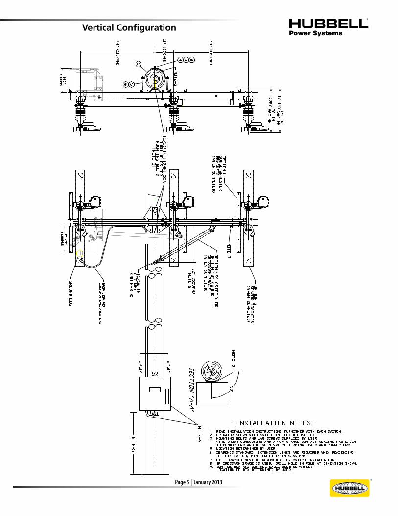
Vertical Configuration
Page 6 | Janurary 2013
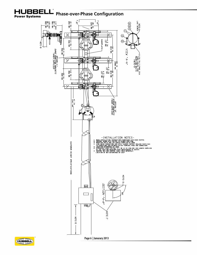
Phase-over-Phase Configuration

Page 7 | January 2013
Inverted Configuration

Page 8 | Janurary 2013
XA R X X X X XXXXX XXX X
Crossarm/Inter-Phase Shaft
S = Steel F = Fiberglass M = Steel crossarm, fiberglass interphase shaft
Position 2:
Position 3:Insulation, kV Impulse(maximum system kV)
1 = 110 porcelain (17.1kV) 3 = 110 polymer (17.1kV) 4 = 150 polymer (29kV) 6 = 150 polymer (38kV grounded-wye) 7 = 150 polymer Long Leak (39.6") (38kV grounded-wye) Configuration
1 = ‡Horizontal2 = Vertical3 = Ø-over-Ø5 = Inverted
Position 5:
Options by Configuration
Position 4:
†Options H and T, Captive Hardware and Terminal Connectors, cannot be ordered together.
14.4kV, 25kV or 34.5kV 900 Amperes Continuous/Interrupt
Replacement Parts C8180001 Standard Interrupter (all Configurations)E8181000P Live Parts (all Ratings & Configurations)PSC8180099 Vacuum Interrupter Kit
M = PTAD Crossarm Motor Operator and Control
B = Sensor Brackets † H = Captive Hardware L = Surge Arrester Brackets S = Steel Crossarm Brace, only one supplied † T = Terminal Connectors (ATC 1343) W = Wood Crossarm Brace, only one supplied X = Extension Links
‡To specify Offset Control, add 0116 as a suffix after building a complete Catalog Number for all other features.
Positions 6 through 10:See Option Table
for each Configuration
Position 1:1 = Standard Interrupter2 = Vacuum Interrupter(not availablefor hookstickoperated switch)
Ordering Information
for Add-On Motor Operators1. Order AR Switch per Catalog Section 14A.
2. Torsional Motor Operator for Horizontal, Delta or Inverted AR Switches.
PSCB28AA11GO1
Assigned by Manufacturer if RTU and Communication are included (see page 9)
2. Torsional Motor Operator for Vertical and Phase-over-Phase AR Switches.
PSCB29AA04GO1
Assigned by Manufacturer if RTU and Communications are included (see page 9)
for Fully-Automated AR Switches
Positions 11 through 14:Assigned by Manufacturer if RTU and Communications are included (see page 9)

Page 9 | January 2013
Prepared by
Purchaser
Contractor (if applicable)
Required delivery date
Date
User
Automation contact
Remote Terminal Unit (RTU)Installed by
Model/Part No.
Number of RTU analog inputs
Modem ❑ No ❑ Yes Baud rate:
Purchased by ❑ HPS❑ Customer
Manufacturer contact
Type of master station
RTU protocol
❑ HPS ❑ Customer❑ Provisions only
Communications DeviceCommunications device provided by❑ HPS ❑ Customer ❑ NoneManufacturer
Manufacturer contact
Antenna purchased by❑ HPS ❑ Customer
Communications device installed by❑ HPS ❑ Customer ❑ Provisions onlyManufacturer part/model
Phone no.
Antenna manufacturer/model
Type ❑ Land line ❑ Fiber optics ❑ Radio ❑ Other (specify)
System Information
Operating system voltage
Normal load current
BIL required
Max. available fault current
Local AC available ❑ 120 ❑ 240Solidly grounded system ❑ Yes ❑ No
Switch Information - New Installation
Switch Information - Retrofit
Contractor phone no.
Sensors
No. of voltages Primary/secondary voltage
Primary/secondary currentNo. of currents
Sensor cable length Manufacturer
Automated Distribution Equipment InquiryTo be completed by Sales Representative
Literature ship to address
Voltage ❑ 15 kV ❑ 25 kV ❑ 35 kVManufacturer
Pole ❑ Wood ❑ Other (drawings required)
Control ❑ Down-the-pole ❑ Hook stickConfiguration ❑ Horizontal❑ Phase-over-Phase ❑ Vertical ❑ Delta
Model
Voltage ❑ 15 kV ❑ 25 kV ❑ 35 kVCatalog Number
Additional Options ❑ Sensor Brackets ❑ Control Insulator ❑ Captive Hardware ❑ Surge Arrester Brackets ❑ Extra Control Pipe ❑ Crossarm Brace ❑ Extension Links
Control ❑ Down-the-pole ❑ Crossarm OperatorConfiguration ❑ Horizontal ❑ Phase-over-Phase ❑ Vertical ❑ Delta
Crossarm ❑ Steel ❑ Fiberglass

Page 10 | Janurary 2013
NOTES

Page 11 | January 2013
NOTES
Page 12 | Janurary 2013
NEVER COMPROMISE™
www.hubbellpowersystems.com
• 8100 Churchill Avenue • Leeds, Alabama 35094 • (205) 699-0840
NOTE: Hubbell has a policy of continuous product improvement. We reserve the right to change design and specifications without notice. ©Copyright 2013 Hubbell Incorporated
JAN 20132M RGS 01/13
Catalog 14C
NOTICE: For the latest revision of our Catalog and Literature, click here or visit our web site: www.hubellpowersystems.com