cat5 hd extender
TRANSCRIPT

CAT5 HD Extender 2305-4339
User Manual v1.0

Introduction
Thank you for purchasing the 2305-4339 CAT5 HD Extender. With the 2305-4339, you can send high-definition audio and video from one or more sources to one or more displays over an Ethernet network. Furthermore, the 2305-4339 can also relay IR remote control signals, as well as PS/2 keyboard and mouse inputs from a remote display location to a source PC or consumer electronics device.
IN ORDER TO PREVENT DAMAGE, READ THIS MANUAL IN ITS ENTIRETY BEFORE ATTEMPTING TO CONNECT OR POWER UP
ANY SINGLE DEVICE OR COMPONENT!
Hardware
TX One-port Transmitter
(PCA – PC Adapter)
Remote On/Off switch STATUS LED VGA pass-through output POWER LED
DC input jack RJ45 network jack DVI/VGA select switch Audio ports USB to PC Ext. IR port DVI-I video input Reset button

Port / Connector Purpose DC input Jack 5V DC power input USB to PC Keyboard and mouse input to PC Remote On/Off Enables / Disables peripherals connected to receiver unit External IR port Connects to IR emitter VGA pass-through Allows you to connect a local VGA monitor. Works only if source is also VGA. DVI/VGA select Selects between the VGA or the DVI-D pins on the DVI-I input connector DVI-I input Video signal input – utilizes either DVI-D or the VGA signals through the select switch Status LED Displays network connection status Power LED Displays power and operation mode status Audio ports Audio signal input from source to RX (speaker), and output audio from RX to PC (mic) Reset button Resets unit, and provides operation mode selection Ethernet port(s) 10/100 Ethernet connection(s) to RX unit(s) through LANs or direct connections ACCESSORIES:
Seven-port Transmitter
(PCA – PC Adapter)
STATUS LED Remote On/Off switch POWER LED
DC input jack Ext. IR jack DVI-I video input Reset button 7x 10/100 Ethernet ports USB to PC DVI/VGA Audio ports VGA pass-through
IR Transmitter External IR Receiver
VGA-M to DVI-F adapter
DVI-M to VGA-F adapter
Cables

Port / Connector Purpose DC input Jack 5V DC power input PS/2 connectors PS/2 keyboard and mouse input for remote PC control IR receiver window Receives IR remote control signals External IR jack Connects to external IR receiver Source button Multifunction button that allows selection of various sources and other functions DVI-I output Video signal output – transmits both DVI-D and VGA signals simultaneously Status LED Displays network connection status Power LED Displays power and operation mode status Audio ports Audio signal input from mic to TX, and output audio from TX to speakers Reset button Resets unit, and provides operation mode selection Ethernet port 10/100 Ethernet connection from TX unit(s) through LAN or direct connection
RX One-port Receiver
(TVA – TV Adapter)
IR receiver window External IR jack POWER LED SOURCE button STATUS LED
DC input jack PS/2 keyboard and mouse ports Audio ports RJ45 network jack DVI-I video output Reset button

Features and Specifications
• Very low latency Audio / SD and HD Video transmission over Ethernet networks
• Send video from multiple sources to multiple destinations over the same Ethernet network
• Adjustable bandwidth
• Receivers can select which source transmitter to display using pushbutton and OSD
• Standard 38 kHz IR remote control repeater from receiver back to transmitter
• Accepts VGA and DVI-D input signals, including HDMI (NOTE: HDCP and digital audio are not supported, and requires DVI-HDMI adapter, not included)
• Accepts stereo audio input
• Works with any computer operating system
• Remote On/Off switch at transmitter disables peripherals connected to receiver
• Relays mic input from receiver back to transmitter
• Transmitter accepts video resolutions from 640 x 480 to 1920 x 1080, from 60Hz to 70Hz refresh
• Built-in scaler scales output video to display’s capability regardless of input video resolution
• Receiver output resolutions and frame rates are as follows: o 640 x 480 70 fps o 720 x 480 60 fps o 720 x 576 50 fps o 800 x 600 70 fps o 1024 x 768 60 fps o 1280 x 720 30 fps o 1280 x 1024 30 fps
o 1360 x 768 30 fps o 1400 x 1050 30 fps o 1440 x 900 30 fps o 1600 x 1200 30 fps o 1680 x 1050 30 fps o 1920 x 1080 25 fps
• Receiver outputs both DVI-D and VGA signals, regardless of input signal on transmitter
• Built-in browser-based configuration for easy user-setting of “Operational IP address” and device naming
• Permanent, hard-coded “Setup IP address” are as follows: o Transmitter (PCA) 192.168.168.21 o Receiver (TVA) 192.168.168.22
• STATUS LED colors: o Off No network connection o Green Network connected o Blinking green Network activity o Orange/Red High network bandwidth usage
• POWER LED colors: o Off Unpowered o Green Powered on and connection established with corresponding TX or RX unit o Red Powered on, but no connection to corresponding TX or RX unit o Blinking Red Reset button held down, ready to enter Setup mode o Orange Unit is in Setup Mode

Configuration and Setup
1. You will need to set fixed IP addresses for each of your 2305-4339 devices. This is necessary for proper operation, and so that the 2305-4339 units will not interfere with any other devices on your network. However, you can skip setting the IP addresses on the units, and go to Step 2, only if:
• The TX and RX units are connected only by an Ethernet cable, with no router or switch in between (one-to-one operation):
• There is only one TX unit, and one or more RX units are connected through a switch, but no PCs or routers are connected to that switch (one-to-many operation):
• There is only one TX unit, and one or more RX units are connected through a switch. PCs and/or routers are connected to that switch, but reside on a subnet other than 192.168.168.x (one-to-many operation):
TX RX
TX RX
RX
TX RX
RX
. . . . . .
PCs on 192.168.1.x subnet

1.1. First, you will need to connect a computer using an Ethernet cable to each 2305-4339 (TX and RX) unit in order to access its configuration web page. In your computer’s network adapter settings, give it a fixed IP address of 192.168.168.100, subnet mask 255.255.255.0.
In Windows XP, this can be done using the following procedure:
1.1.1. Go to CONTROL PANEL > NETWORK CONNECTIONS > right-click LOCAL AREA CONNECTIONS, then click on STATUS. Click on the PROPERTIES button, scroll-down, and double-click on “Internet Protocol (TCP/IP)”. In the next window, enter the IP address and subnet as shown below:
1.1.2. Click OK, then OK, then CLOSE.
1.2. Now, prepare the 2305-4339 unit to be configured and a small blunt instrument such as a toothpick or straightened paperclip. Make sure the unit is unpowered and not connected to anything.
1.3. Using the blunt instrument, hold down the RESET button, then power on the unit by plugging in the power adapter. When you see the POWER LED blink RED, release the RESET button, then the POWER LED should turn ORANGE. Only when the POWER LED is ORANGE can you access the unit’s configuration web page, also known as Setup Mode.

1.4. Next, connect the unit to your computer using any standard Ethernet cable. Once the cable is connected, the STATUS LED turns green.
1.5. Open a browser, and enter the following “Setup IP address”, depending if the unit you are configuring is a transmitter or a receiver:
1.5.1. Transmitter (PCA) 192.168.168.21 1.5.2. Receiver (TVA) 192.168.168.22
1.6. You will see the settings web page where you can enter the “Operational IP address”. This address is in
effect only when the device is in normal AV operation (when POWER LED is not ORANGE), and is different from the “Setup IP address” above, which is permanent and cannot be changed. The “Setup IP address” in effect only when the POWER LED is ORANGE. Even if you have set an “Operational IP address” previously, entering this Setup mode will revert all settings back to the factory defaults:

Now, you can enter an IP address for this unit, and also a friendly device name. Some rules-of-thumb:
• Because the 2305-4339 units will not be interacting with any other devices on your network, the IP address should be on a subnet which is currently not used by any device on your network. For example, if your router and DHCP server use the 192.168.1.x subnet, you set all your 2305-4339 devices to another subnet, such as its current factory subnet 192.168.168.x. However, be sure that every 2305-4339 unit has a unique address.
• For the Device Name, use a descriptive name which can easily be identified by the user. See example below.
• When done, click on SAVE, then EXIT. The unit will restart. 1.7. Disconnect the Ethernet cable from your computer and the unit. The 2305-4339 unit is now configured
with the IP address 192.168.168.200, and Device Name “Lobby TV”. 1.8. Repeat steps 1.2 to 1.7 for all 2305-4339 units in your setup, making sure each unit has a different IP
address, but MUST HAVE the same first three octets (ie. 192.168.168.x). Here is an example: Unit Type Device Name IP Address RX Lobby TV 192.168.168.200 RX Upstairs TV 192.168.168.201 TX DVD-Player-1 192.168.168.202 TX DVR 192.168.168.203
1.9. Go back to the TCP/IP properties window as shown in step 1.1.1 above, and change it back to “Obtain an IP address automatically”. Click OK, then OK, then CLOSE.
Permitted IP Address Ranges: • 192.168.0.0 to 192.168.254.254 • 172.16.0.0 to 172.31.254.254 • 10.0.0.0 to 10.254.254.254
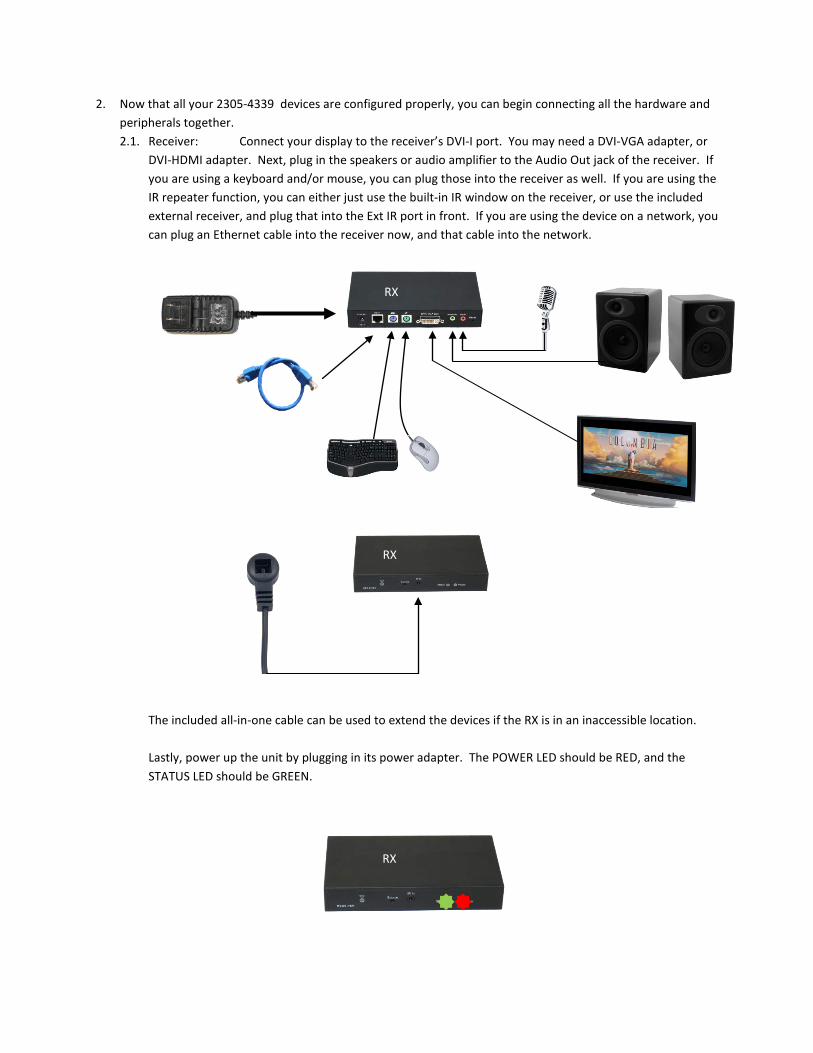
2. Now that all your 2305-4339 devices are configured properly, you can begin connecting all the hardware and peripherals together. 2.1. Receiver: Connect your display to the receiver’s DVI-I port. You may need a DVI-VGA adapter, or
DVI-HDMI adapter. Next, plug in the speakers or audio amplifier to the Audio Out jack of the receiver. If you are using a keyboard and/or mouse, you can plug those into the receiver as well. If you are using the IR repeater function, you can either just use the built-in IR window on the receiver, or use the included external receiver, and plug that into the Ext IR port in front. If you are using the device on a network, you can plug an Ethernet cable into the receiver now, and that cable into the network. The included all-in-one cable can be used to extend the devices if the RX is in an inaccessible location. Lastly, power up the unit by plugging in its power adapter. The POWER LED should be RED, and the STATUS LED should be GREEN.
RX
RX
RX

2.2. Transmitter: The included all-in-one cable is used to conveniently connect a PC to the transmitter Connect your computer or source device to the transmitter’s DVI-I port. You may need a DVI-VGA or DVI-HDMI adapter. If the signal coming from the source is DVI or HDMI, be sure to set the DVI/VGA switch to DVI. If the signal is VGA, set the switch to VGA. Next, plug one end of the audio cable into the Audio In jack on the transmitter, and the other end into your computer or source device’s Line Out or Speaker Out jack. The audio cable also has a pass-through female connector for a local speaker connection. If you are using a keyboard and/or mouse, plug in the USB cable into the USB port on the transmitter, and the other end into a free USB port on your computer. If you are using the IR repeater function, plug the included IR emitter into the IR Out jack, and point the IR emitter to the device being controlled. If you are using the device on a network, you can plug an Ethernet cable into the receiver now, and that cable into the network, or you can plug the other end directly into the transmitter.
Stereo HDMI Out Out
HDMI-DVI-I Adapter
(not included)
Audio output
Line-In or Mic input
DVI or VGA output
USB
Setup with a PC
Setup with a Consumer Electronics device such as a DVD player with HDMI output
TX
TX
Local speaker
Local speaker

At this point, you can also plug in a local VGA monitor to the transmitter. But note that the local VGA monitor will only work if the input signal is also VGA. Lastly, power up the unit by plugging in it’s power adapter. The POWER LED should be RED, and the STATUS LED should be GREEN.
2.3. 7-port Transmitter: The 7-port TX is identical as the1-port TX, except that it has a built-in 7-port Ethernet switch with IGMP snooping, designed specifically for use with multiple 2305-4339 units. You can plug seven other 2305-4339 devices directly into the 7-port TX, without the need for additional network hardware.
Direct to receivers
AND/OR
To other switches
. . .
TX
TX
7-port TX
RX
RX
RX

2.4. Repeat steps 2.1 to 2.3 above for all 2305-4339 devices that would be in use. 2.5. IMPORTANT: WHEN USING MULTIPLE TRANSMITTERS ON THE SAME NETWORK
Transmitters can consume up to 99% of available bandwidth on a 100Mb/s Ethernet link when running at 1080p. Therefore, the ideal method of connecting multiple transmitters to multiple receivers is to have all transmitters connected to a single switch using a direct connection, without any additional 100Mb/s switches in between. This ensures that each transmitter has a full 100Mb/s link to the switch: An alternative is to have a Gigabit link in between switches to accommodate the additional bandwidth used by the multiple transmitters:
Most importantly, switches used with multiple 2305-4339 transmitters must have “IGMP snooping” functionality. This is critical in preventing multiple multicast streams from flooding the entire network, causing all other network devices such as computers to have slow or no access to the network. The IGMP snooping feature in switches intelligently identifies and routes the AV packets from the transmitters only to the appropriate RX destinations, not to computers that don’t need it. This frees up bandwidth thereby allowing other network traffic to pass.
TX
TX
TX
TX
TX
TX
RX
RX
RX
RX
RX
RX
100Mb/s switch with IGMP snooping
100Mb/s switch w/ gigabit port and IGMP snooping
100Mb/s switch w/ gigabit port and IGMP snooping
100Mb/s
100Mb/s
100Mb/s
100Mb/s
100Mb/s
100Mb/s
100Mb/s
100Mb/s
100Mb/s
100Mb/s
100Mb/s
100Mb/s
1000Mb/s

OSD Functions
The RX includes an On-Screen Display (OSD) menu which is enabled by pressing the SOURCE button on the front panel. The OSD menu provides the user with various settings and the ability to select which source video stream to display.
• Press the SOURCE button to cycle through the various options.
• To select an item, leave the desired item highlighted for three seconds.
1. RX (TVA) Setup via OSD
To set the options of the RX (TVA) unit, make sure that the RX is not connected to the network. Power it up with a display, and the following message will appear:
Wait a few seconds until the message disappears, the press the SOURCE button to bring up the OSD:
• REFRESH will search the network again for any enabled TX (PCA) units
• TVA SETTING brings up the options for the RX. Select this option to go to the next menu below
• TVA OFF disables the RX from displaying any video or audio
• AUDIO INPUT brings up the MIC input settings menu, see below
• IR INPUT brings up the IR remote input menu settings menu, see below
• RETURN goes to the previous menu
• MIC IN DISABLE turns off the MIC input to save bandwidth
• MIC IN ENABLE turns on the MIC input
• RETURN goes to the previous menu
• IR DISABLE turns off the IR repeater to save bandwidth
• INTERNAL IR enables the IR repeater using the front-panel IR receiver
• EXTERNAL IR enables the IR repeater using the external IR jack
• RETURN goes to the previous menu
SEARCHING PCA . . . NOT FOUND
> REFRESH > TVA SETTING > TVA OFF
> AUDIO INPUT > IR INPUT > RETURN
> MIC IN DISABLE > MIC IN ENABLE > RETURN
> IR DISABLE > INTERNAL IR > EXTERNAL IR > RETURN
SOURCE button

2. Run-time OSD
When the RX is streaming video from a source transmitter, the OSD options are different than in #1 above. Again, pressing the SOURCE button brings up the OSD:
• In the Run-Time OSD, the list of available transmitters is listed first. In the example here, two transmitters are shown, “DVD-1” and “APPLE-3”. The numbers in the parentheses are its MAC addresses. The “connected” status indicates that this RX unit is currently showing the AV stream from the transmitter “DVD-1”. To select another transmitter’s content to display, simply press the SOURCE button again until it is highlighted, wait three seconds, and its stream will be shown instead.
• VGA SYNC (appears only if input at transmitter is VGA) re-synchronizes VGA signal
• REFRESH will search the network again for any enabled TX (PCA) units
• PCA SETTING brings up the options for the currently selected transmitter. Select this option to go to the next menu below
• TVA OFF disables the RX from displaying any video or audio
• EXIT turns off the OSD
• MULTI/ONE TVA brings up the MULTI/ONE menu below
• BANDWIDTH SETTING brings up the BANDWIDTH menu below
• INFORMATION displays the current operating modes of both the receiver and currently selected transmitter
• EXIT turns off the OSD
• ONE TVA ONLY sets the currently selected transmitter to Unicast mode wherein only this receiver can display that transmitter’s content
• MULTI TVA sets the currently selected transmitter to Multicast mode wherein more than one receiver can display that transmitter’s content
• EXIT turns off the OSD
> DVD-1 (00:00:20) connected > APPLE-3 (00:00:26) > REFRESH > VGA SYNC > PCA SETTING > TVA OFF > EXIT
> MULTI/ONE TVA > BANDWIDTH SETTING > INFORMATION > EXIT
> ONE TVA ONLY > MULTI TVA > EXIT

• LOW, MID and HIGH are various bandwidth settings which can be selected to save network bandwidth. These settings are effective only when the content being displayed is 1280x720 or higher
• EXIT turns off the OSD
• Here is the INFORMATION screen. It displays all the relevant information about the RX (TVA) and the currently selected transmitter (PCA).
Keyboard, Mouse, Mic and IR Remote Repeater Use
Input devices can be connected to the RX in order to control the transmitting device connected to a 1-port or 7-port TX. These devices can be a PS/2 keyboard, PS/2 mouse, microphone, or standard IR remote control. The microphone is set up in a similar way – simply plug in the mic or other low-level audio source into the MIC-IN jack on the RX. Make sure that the MIC IN is enabled in the OSD.
As for the remote repeater, you can either use the built-in or external IR receiver on the RX side. On the transmitting side, plug in the included IR transmitter into the IR OUT port, and aim it directly at the AV device’s IR receiver window. Ensure that the proper IR setting is selected in the OSD.
> LOW > MID > HIGH > EXIT
PCA PROTOCOL VERSION 0.91 SUPPORT MULTI TVA BANDIWDTH High DVI IN 1024*768 TVA – Master PROTOCOL VERSION 0.91 DVI OUT 1024*768 MIC IN INTERNAL IR
TX RX
RX

Simply plug in the PS/2 devices into their respective ports on the transmitter, then power up the receiver. On the transmitter side, use the included USB cable to connect the transmitter’s USB port to an unused USB port on the computer. Your computer may prompt you that it has detected new hardware, so just follow the prompts to complete the installation process.
One important note when using multiple receivers per transmitter: Only the MASTER RX will have the functional keyboard, mouse, and IR port with respect to each transmitter. To set which RX is the MASTER unit, turn off all other RX units, power up the desired unit first, and allow it to establish a connected to the transmitter. See the INFORMATION OSD screen above on how to display the RX’s MASTER/SLAVE status. When the desired RX unit is already set as MASTER, all other RX units can be powered up.
Remote On – Off Switch
Each TX transmitter unit has a front-panel REMOTE ON/OFF switch. This switch disables all input devices (keyboard, mouse, and IR remote control on a Master RX) from controlling the computer or AV device connected to the transmitter.
TX
RX RX
100Mb/s switch
MASTER unit – connected 1st
SLAVE units - connected after MASTER
PC
RX
Remote On/Off switch
USB
TX
RX

©2009 Eiki International, Inc.
No part of this User Guide can be copied, reproduced, transmitted, or otherwise used without the prior written
consent of Eiki International Inc.