casting by amjad
TRANSCRIPT

Steps involved in making a casting:1. Make the pattern out of Wood , Metal or Plastic.2. Prepare the necessary sand mixtures for mould and core making.3. Prepare the Mould and necessary Cores.4. Melt the metal/alloy to be cast.5. Pour the molten metal/alloy into mould and remove the casting
from the mould after the metal solidifies.6. Clean and finish the casting.7. Test and inspect the casting.8. Remove the defects, if any.9. Relieve the casting stresses by Heat Treatment.10. Again inspect the casting.11. The casting is ready for shipping.

Pattern Making:
A Pattern is a model or the replica of the object to be cast.
Except for the various allowances a pattern exactly resembles the casting to be made.
A pattern is required even if one object has to be cast.
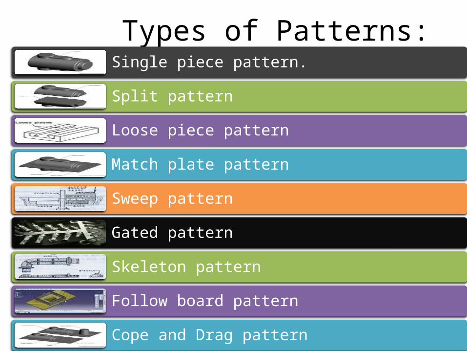
Types of Patterns:Single piece pattern.
Split pattern
Loose piece pattern
Match plate pattern
Sweep pattern
Gated pattern
Skeleton pattern
Follow board pattern
Cope and Drag pattern
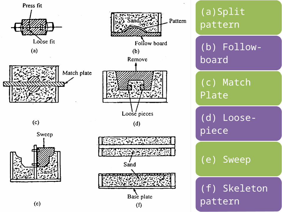
(a)Split pattern
(b) Follow-board
(c) Match Plate
(d) Loose-piece
(e) Sweep
(f) Skeleton pattern

ISE 316 - Manufacturing Processes Engineering
Figure 11.3 Types of patterns used in sand casting: ‑(a) solid pattern(b) split pattern(c) match plate pattern‑(d) cope and drag pattern

Fig: Single piece pattern
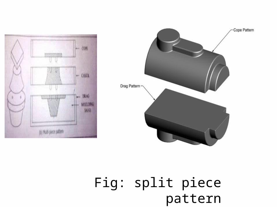
Fig: split piece pattern
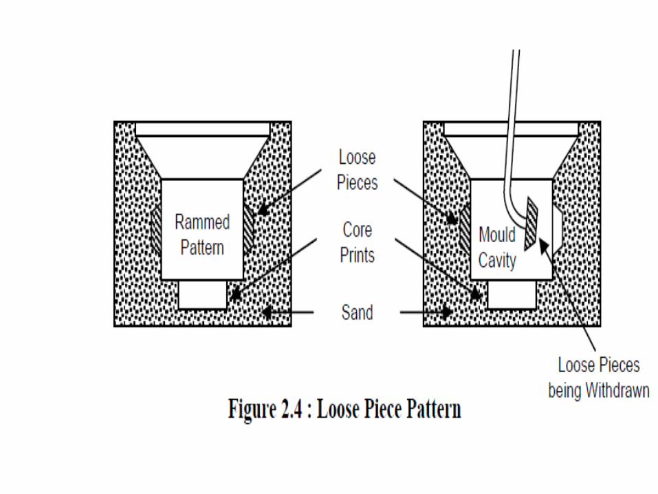

Fig: Match plate pattern

Sweep pattern:

castings
Gating system
GATED PATTRN

Fig: Cope and drag pattern

Materials for making patterns:WOOD
METAL
PLASTIC
PLASTER
WAX
The pattern material should be:1. Easily worked, shaped and joined.2. Light in weight.3. Strong, hard and durable.4. Resistant to wear and abrasion .5. Resistant to corrosion, and to chemical
reactions.6. Dimensionally stable and unaffected by
variations in temperature and humidity.7. Available at low cost.

Types of Pattern Allowances:The various pattern allowances are:
1. Shrinkage or contraction allowance.2. Machining or finish allowance.3. Draft of tapper allowances.4. Distortion or chamber allowance.
5. Shake or rapping allowance.

1.Shrinkage Allowance: All most all cast metals shrink or contract
volumetrically on cooling.
The metal shrinkage is of two types:
1. Liquid Shrinkage: 2. Solid Shrinkage:
2. Machining Allowance: A Casting is given an allowance for
machining, because:i. Castings get oxidized in the mold and during
heat treatment; scales etc., thus formed need to be removed.
ii. It is the intended to remove surface roughness and other imperfections from the castings.
iii. It is required to achieve exact casting dimensions.
iv. Surface finish is required on the casting.

3. Draft or Taper Allowance:
It is given to all surfaces perpendicular to parting line.
Draft allowance is given so that the pattern can be easily removed from the molding material tightly packed around it with out damaging the mould cavity.
3. Draft or Taper Allowance:
It is given to all surfaces perpendicular to parting line.
Draft allowance is given so that the pattern can be easily removed from the molding material tightly packed around it with out damaging the mould cavity.


Fig: taper in design

4. Distortion or cambered allowance:
A casting will distort or wrap if :i. It is of irregular shape,ii. All it parts do not shrink uniformly i.e., some
parts shrinks while others are restricted from during so,
iii. It is u or v-shape
5. Shake allowance:A pattern is shaken or rapped by striking the same
with a wooden piece from side to side. This is done so that the pattern a little is loosened in the mold cavity and can be easily removed.
In turn, therefore, rapping enlarges the mould cavity which results in a bigger sized casting.
Hence, a –ve allowance is provided on the pattern i.e., the pattern dimensions are kept smaller in order to compensate the enlargement of mould cavity due to rapping.

Classification Of
Moulding Sands

A)Natural sand is the one which is available from natural deposits. Only additives and water need be added to it to make it satisfactory for molding.
B)Synthetic sand is prepared by mixing a relatively clay free sand having specified type of sand grain, with specified type of clay binder as well as water and other additives.

1. Green sand: It is sand used in the wet condition for making the mould. It is mixture of silica sand with 15-25 per cent clay and 6-8 per cent waterThe sand can be easily worked with hand to give it any desired shape.This sand is used for producing small to medium sized moulds which are not very complex

2. Dry sand:Dry sand is the green sand that has been dried or baked after preparing the mould.Drying sand gives strength to the mould so that it can be used for larger castings
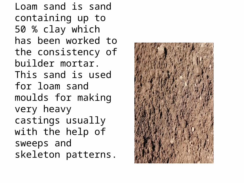
3. Loam sand:Loam sand is sand containing up to 50 % clay which has been worked to the consistency of builder mortar.This sand is used for loam sand moulds for making very heavy castings usually with the help of sweeps and skeleton patterns.

4. Parting sand:-This sand is used during making of the mould to ensure that green sand does not stick to the pattern and the cope and drug parts can be easily separated for removing the pattern without causing any damage to the mould.-Parting sand consists of fine grained clay free dried silica sand, sea sand or burnt sand with some parting compounds.-The parting compounds used include charcoal, ground bone and limestone, groundnut shells, talc and calcium phosphate.

5. Facing sand:-Facing sand is the sand which covers the pattern all around it. The remaining box is filled with ordinary floor sand.-Facing sand forms the face of the mould and comes in direct contact with the molten metal when it is poured.-High strength and refractoriness are required for this sand.-It is made of silica sand and clay without the addition of any used sand.
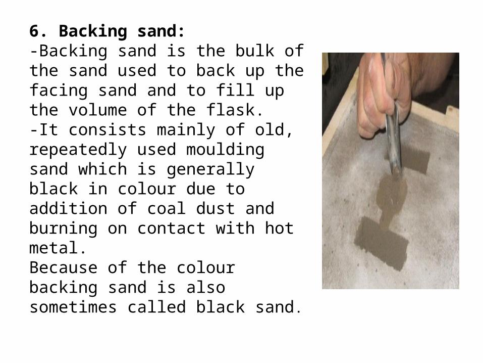
6. Backing sand:-Backing sand is the bulk of the sand used to back up the facing sand and to fill up the volume of the flask.-It consists mainly of old, repeatedly used moulding sand which is generally black in colour due to addition of coal dust and burning on contact with hot metal.Because of the colour backing sand is also sometimes called black sand.
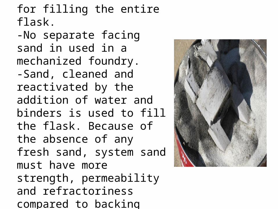
7. System sand:-This is the sand used in mechanized foundries for filling the entire flask.-No separate facing sand in used in a mechanized foundry.-Sand, cleaned and reactivated by the addition of water and binders is used to fill the flask. Because of the absence of any fresh sand, system sand must have more strength, permeability and refractoriness compared to backing sand.
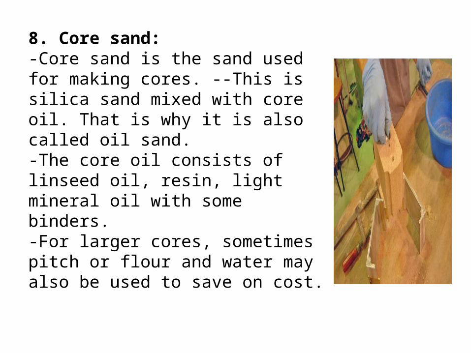
8. Core sand:-Core sand is the sand used for making cores. --This is silica sand mixed with core oil. That is why it is also called oil sand.-The core oil consists of linseed oil, resin, light mineral oil with some binders.-For larger cores, sometimes pitch or flour and water may also be used to save on cost.

GENERAL PROPERTIES OF
MOLDING SANDS

1. Green strength: The green sand, after water has been mixed into it, must have adequate strength and plasticity for making and handling of the mold.2. Dry strength: As a casting is poured, sand adjacent to the hot metal quickly loses its water as steam. The dry sand must have strength to resist erosion, and also the pressure of the molten metal, or else the mold may enlarge.3. Hot strength. After the moisture has evaporated, the sand may be required to possess strength at some elevated temperature.4. Permeability/Porosity. Heat from the casting causes a green sand ‐mold to evolve a great deal of steam and other gases. The mold must be permeable, i.e. porous, to permit the gases to pass off, or the casting will contain gas holes.5. Thermal stability. Heat from the casting causes rapid expansion of the sand surface at the mold metal interface. The ‐mold surface may then crack, buckle, or flake off (scab) unless the molding sand is relatively stable dimensionally under rapid heating.

6. Refractoriness. Higher pouring temperatures, such as those for ferrous alloys at 2400 to 3200 F, require greater refractoriness of the sand. Low ‐pouring temperature metals, for example, aluminum, poured at 1300 F, do ‐not require a high degree of refractoriness from the sand. 7. Plasticity or flow-ability : It is the measure of the molding sand to flow around and over a pattern during ramming and to uniformly fill the flask. 8. Cohesiveness: It is the property of sand which hold grains together. 9. Collapsibility. Heated sand which becomes hard and rocklike is difficult to remove from the casting and may cause the contracting metal to tear or crack.10. Adhesiveness: This is the property of sand mixture to adhere to another body (here, the molding flasks). The molding sand should cling to the sides of the molding boxes so that it does not fall out when the flasks are lifted and turned over 11. Offers ease of sand preparation and control.12. Removes heat from the cooling casting. 13.Produces good casting finish14.It is reusable.
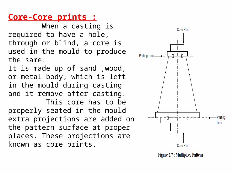
Core-Core prints : When a casting is required to have a hole, through or blind, a core is used in the mould to produce the same.It is made up of sand ,wood, or metal body, which is left in the mould during casting and it remove after casting. This core has to be properly seated in the mould extra projections are added on the pattern surface at proper places. These projections are known as core prints.
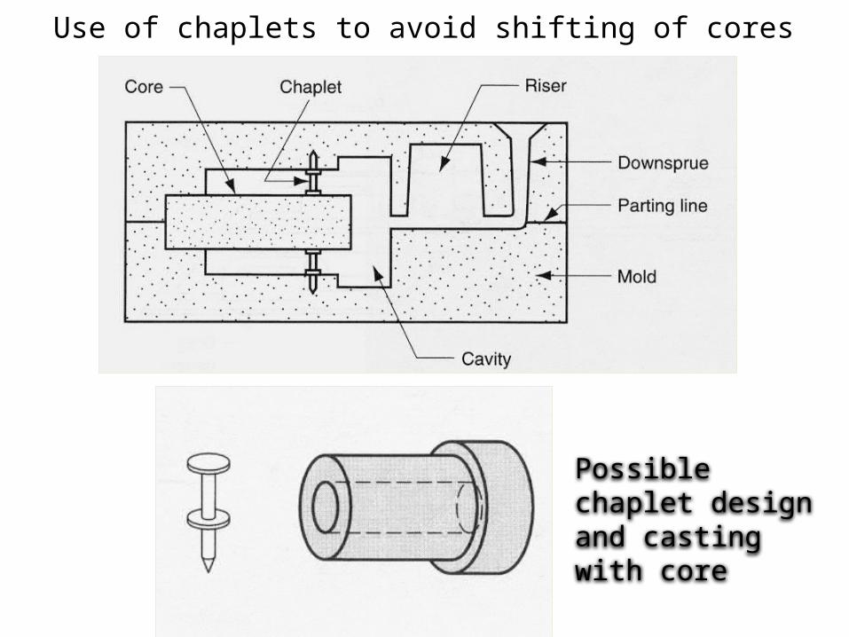
Use of chaplets to avoid shifting of cores
Possible chaplet design and casting with core

Element Of Gating System


Casting Terms:
2. Pattern: It is the replica of the final object to be made. The mold cavity is made with the help of pattern.
3. Parting line: This is the dividing line between the two molding flasks that makes up the mold.
Pattern

4. Pouring basin: A small funnel shaped cavity at the top of the mold into which the molten metal is poured.
5. Sprue: The passage through which the molten metal, from the pouring basin, reaches the mold cavity. In many cases it controls the flow of metal into the mold.

6. Runner: The channel through which the molten metal is carried from the sprue to the gate.
7. Riser: A column of molten metal placed in the mold to feed the castings as it shrinks and solidifies. Also known as feed head.
8. Gate: A channel through which the molten metal enters the mold cavity.

9. Core: A separate part of the mold, made of sand and generally baked, which is used to create openings and various shaped cavities in the castings.
10.Chaplets: Chaplets are used to support the cores inside the mold cavity to take care of its own weight and overcome the metallostatic force.
11. Vent: Small opening in the mold to facilitate escape of air and gases.

Furnaces• Melting is an equally important parameter for
obtaining a quality castings. A number of furnaces can be used for melting the metal, to be used, to make a metal casting. The choice of furnace depends on the type of metal to be melted. Some of the furnaces used in metal casting are as following:.
• Crucible furnaces• Cupola• Induction furnace• Eclectic arc furnace
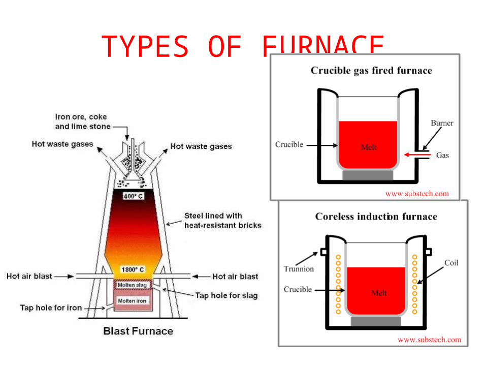
TYPES OF FURNACE

REVERBERATORY FURNACE

ROTARY FURNACE

OPEN HEARTH FURNACE DIAGRAM

CupolaCupola furnaces are tall, cylindrical furnaces used to melt iron and ferrous alloys in foundry operations. Alternating layers of metal and ferrous alloys, coke, and limestone are fed into the furnace from the top. This diagram of a cupola illustrates the furnace's cylindrical shaft lined with refractory and the alternating layers of coke and metal scrap. The molten metal flows out of a spout at the bottom of the cupola. .
Description of CupolaThe cupola consists of a vertical cylindrical steel sheet and lined inside with acid refractory bricks. The lining is generally thicker in the lower portion of the cupola as the temperature are higher than in upper portion.There is a charging door through which coke, pig iron, steel scrap and flux is charged The blast is blown through the tuyeresThese tuyeres are arranged in one or more row around the periphery of cupolaHot gases which move up from the bottom (combustion zone) preheats the iron in the preheating zoneCupolas are provided with a drop bottom door through which debris, consisting of coke, slag etc. can be discharged at the end of the meltA slag hole is provided to remove the slag from the meltThrough the tap hole molten metal is poured into the ladleAt the top conical cap called the spark arrest is provided to prevent the spark emerging to outside
Operation of CupolaThe cupola is charged with wood at the bottom. On the top of the wood a bed of coke is built. Alternating layers of metal and ferrous alloys, coke, and limestone are fed into the furnace from the top. The purpose of adding flux is to eliminate the impurities and to protect the metal from oxidation. Air blast is opened for the complete combustion of coke. When sufficient metal has been melted that slag hole is first opened to remove the slag. Tap hole is then opened to collect the metal in the ladle.


The Electric Arc
Furnace (EAF)

The Electric Arc Furnace (EAF) uses only scrap metal. The process was originally used solely for making high quality steel. Modern electric arc furnaces can make up to 150 tones of steel in a single melt.The electric arc furnace consists of a circular bath with a movable roof, through which three graphite electrodes can be raised or lowered. At the start of the process, the electrodes are withdrawn and the roof swung. The steel scrap is then charged into the furnace from a large steel basket lowered from an overhead travelling crane. When charging is complete, the roof is swung back into position and the electrodes lowered into the furnace. A powerful electric current is passed through the charge, an arc is created, and the heat generated melts the scrap.


CENTRIFUGAL CASTING

Centrifugal casting is a method of casting parts having axial symmetry. The method involves pouring molten metal into a cylindrical mold spinning about its axis of symmetry. The mold is kept rotating till the metal has solidifyThe rotation speed of centrifugal mold is commonly about 1000 RPM (may vary from 250 RPM to 3600 RPM).
Centrifugal casting is carried out as follows:The mold wall is coated by a refractory ceramic coating (applying ceramic slurry, spinning, drying and baking).Starting rotation of the mold at a predetermined speed.Pouring a molten metal directly into the mold (no gating system is employed).The mold is stopped after the casting has solidified.Extraction of the casting from the mold.Non-metallic and slag inclusions and gas bubbles being less dense than the melt are forced to the inner surface of the casting by the centrifugal forces. This impure zone is then removed by machining.Centrifugal casting technology is widely used for manufacturing of iron pipes, bushings, wheels, pulleys bi-metal steel-bronze bearings and other parts possessing axial symmetry.

ApplicationsTypical parts made by this process are pipes, boilers, pressure vessels ,flywheels, cylinder ,liners and other parts that are axi-symmetric. It is notably used to cast cylinder liners and sleeve valves for piston engines, parts which could not be reliably manufactured otherwise.
ISE 316 - Manufacturing Processes Engineering
Shell Molding
Casting process in which the mold is a thin shell of sand held together by thermosetting resin binder

ISE 316 - Manufacturing Processes Engineering
Steps in shell molding: ‑(1) a match plate or cope and drag metal ‑ ‑ ‑
pattern is heated and placed over a box containing sand mixed with thermosetting resin

ISE 316 - Manufacturing Processes Engineering
(2) box is inverted so that sand and resin fall onto the hot pattern, causing a layer of the mixture to partially cure on the surface to form a hard shell
ISE 316 - Manufacturing Processes Engineering
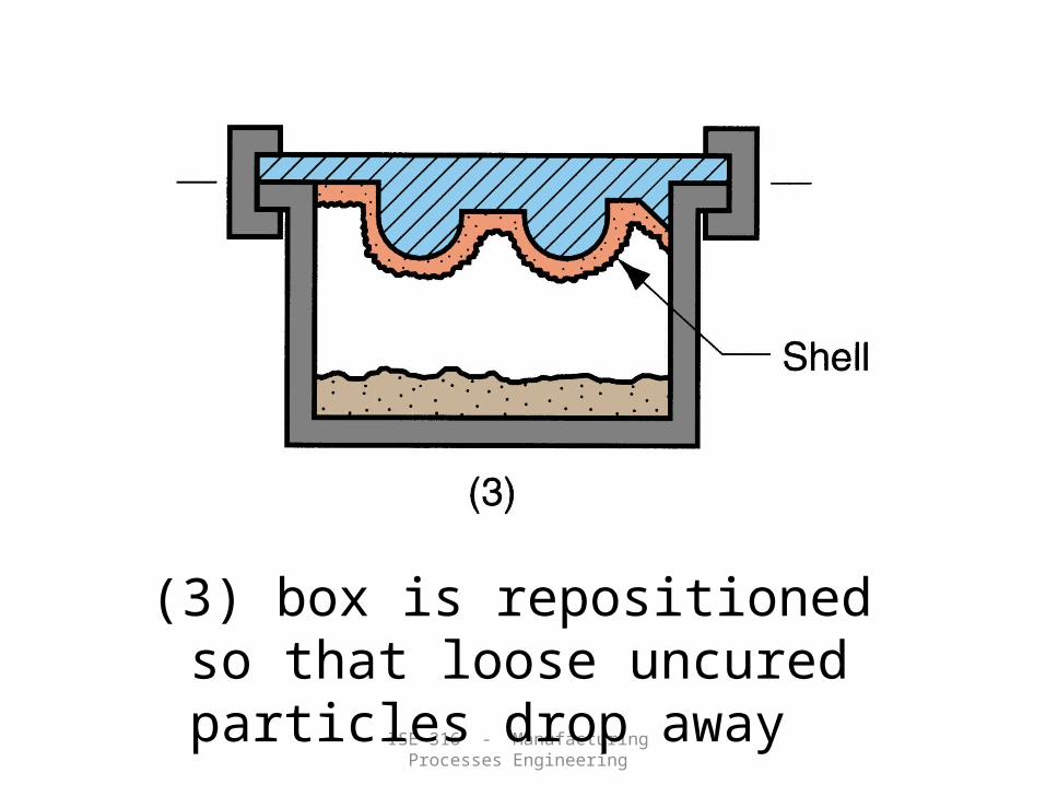
(3) box is repositioned so that loose uncured particles drop away

ISE 316 - Manufacturing Processes Engineering
(4) sand shell is heated in oven for several minutes to complete curing
(5) shell mold is stripped from the pattern

ISE 316 - Manufacturing Processes Engineering
(6) two halves of the shell mold are assembled, supported by sand or metal shot in a box, and pouring is accomplished
(7) the finished casting with sprue removed

Applications: Cylinder heads, connecting rods Engine blocks and manifolds, machine bases, gears, pulleys.

Investment Casting
(or) Lost Wax Method
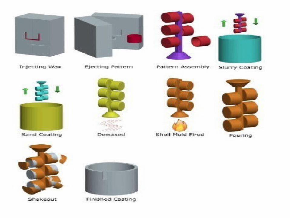
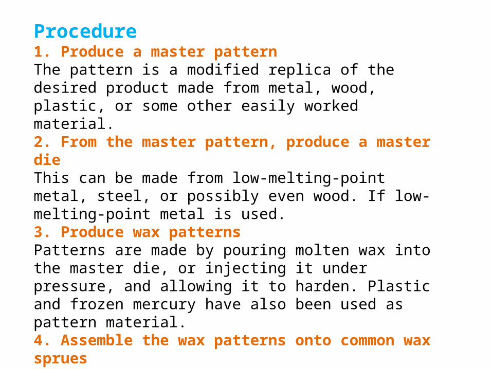
Procedure1. Produce a master patternThe pattern is a modified replica of the desired product made from metal, wood, plastic, or some other easily worked material.2. From the master pattern, produce a master dieThis can be made from low-melting-point metal, steel, or possibly even wood. If low-melting-point metal is used.3. Produce wax patternsPatterns are made by pouring molten wax into the master die, or injecting it under pressure, and allowing it to harden. Plastic and frozen mercury have also been used as pattern material.4. Assemble the wax patterns onto common wax spruesThe individual wax patterns are attached to a central sprues and runner system by means of heated tools and melted wax. In some cases, several pattern pieces may first be united to form a complex.
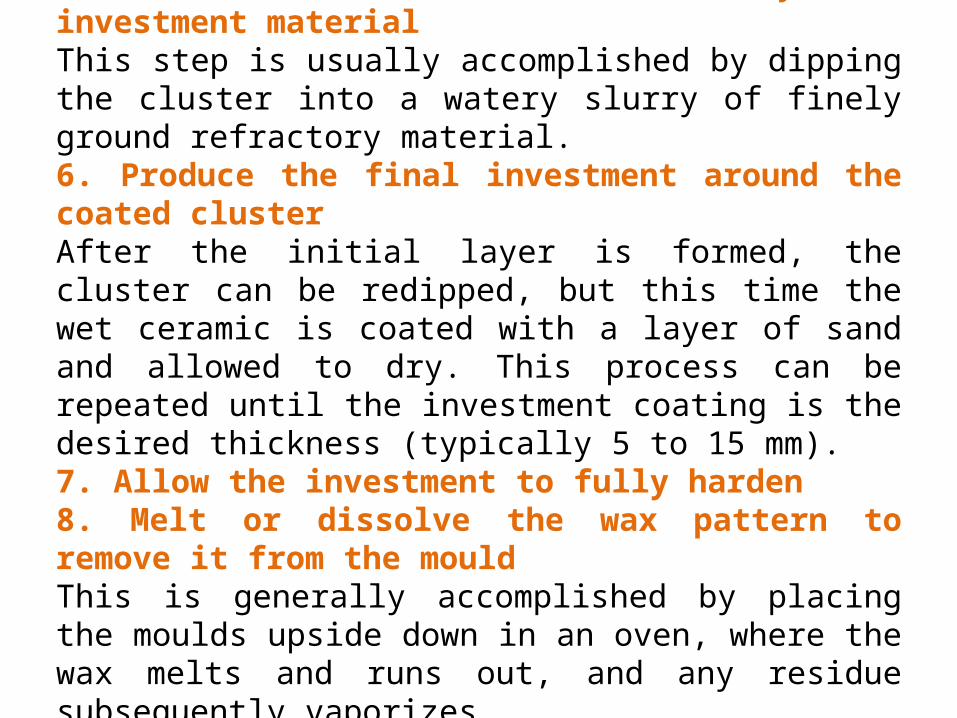
5. Coat the cluster with a thin layer of investment materialThis step is usually accomplished by dipping the cluster into a watery slurry of finely ground refractory material.6. Produce the final investment around the coated clusterAfter the initial layer is formed, the cluster can be redipped, but this time the wet ceramic is coated with a layer of sand and allowed to dry. This process can be repeated until the investment coating is the desired thickness (typically 5 to 15 mm).7. Allow the investment to fully harden8. Melt or dissolve the wax pattern to remove it from the mouldThis is generally accomplished by placing the moulds upside down in an oven, where the wax melts and runs out, and any residue subsequently vaporizes.

9. Preheat the mould in preparation for pouringHeating to 550 to 1100°C (1000 to 2000°F) ensures complete removal of the mould wax, curves the mould to give added strength, and allows the molten metal to retain its heat and flow more readily into all of the thin sections.10. Pour the molten metalVarious methods, beyond simple pouring, can be used to ensure complete filling of the mould, especially when complex, thin sections are involved.11. Remove the casting from the mouldThis is accomplished by breaking the mould away from the casting. Techniques include mechanical vibration and high-pressure water.
ApplicationsThe products made by this process are vanes and blades for gas turbines, shuttle eyes for weaving, pawls and claws of movie cameras, wave guides for radars, bolts and triggers for fire arms, stainless steel valve bodies and impellers for turbo chargers , While investment casting is actually a very old process and has been performed by dentists and jewellers for a number of years.Developments and demands in the aerospace industry, such as rocket components and jet engine turbine blades, required high-precision complex shapes from high-melting-point metals that are not readily machinable.Investment casting offers almost unlimited freedom in both the complexity of shapes and types of materials that can be cast.
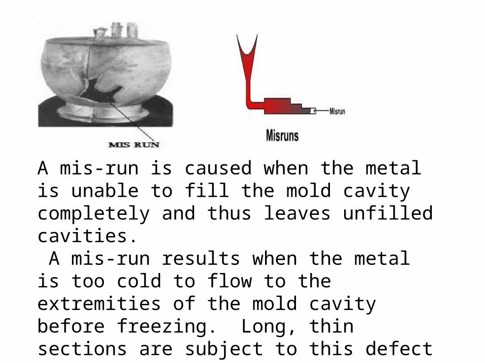
A mis-run is caused when the metal is unable to fill the mold cavity completely and thus leaves unfilled cavities. A mis-run results when the metal is too cold to flow to the extremities of the mold cavity before freezing. Long, thin sections are subject to this defect and should be avoided in casting design.

Metal penetrationWhen molten metal enters into the gaps between sand grains, the result is a rough casting surface. This occurs because the sand is coarse or no mold wash was applied on the surface of the mold. The coarser the sand grains more the metal penetration.

Shrinkage CavitiesThese are caused by liquid shrinkage occurring during the solidification of the casting. To compensate for this, proper feeding of liquid metal is required. For this reason risers are placed at the appropriate places in the mold. Sprues may be too thin, too long or not attached in the proper location, causing shrinkage cavities. It is recommended to use thick sprues to avoid shrinkage cavities.

Mold ShiftThe mold shift defect occurs when cope and drag or molding boxes have not been properly aligned.

A condition existing in a casting caused by the trapping of gas in the molten metal or by mold gases evolved during the pouring of the casting. The defects in this category can be classified into blowholes and pinhole porosity. Blowholes are spherical or elongated cavities present in the casting on the surface or inside the casting. Pinhole porosity occurs due to the dissolution of hydrogen gas, which gets entrapped during heating of molten metal.

A cold shut is caused when two streams while meeting in the mold cavity, do not fuse together properly thus forming a discontinuity in the casting. When the molten metal is poured into the mold cavity through more-than-one gate, multiple liquid fronts will have to flow together and become one solid. If the flowing metal fronts are too cool, they may not flow together, but will leave a seam in the part. Such a seam is called a cold shut, and can be prevented by assuring sufficient superheat in the poured metal and thick enough walls in the casting design
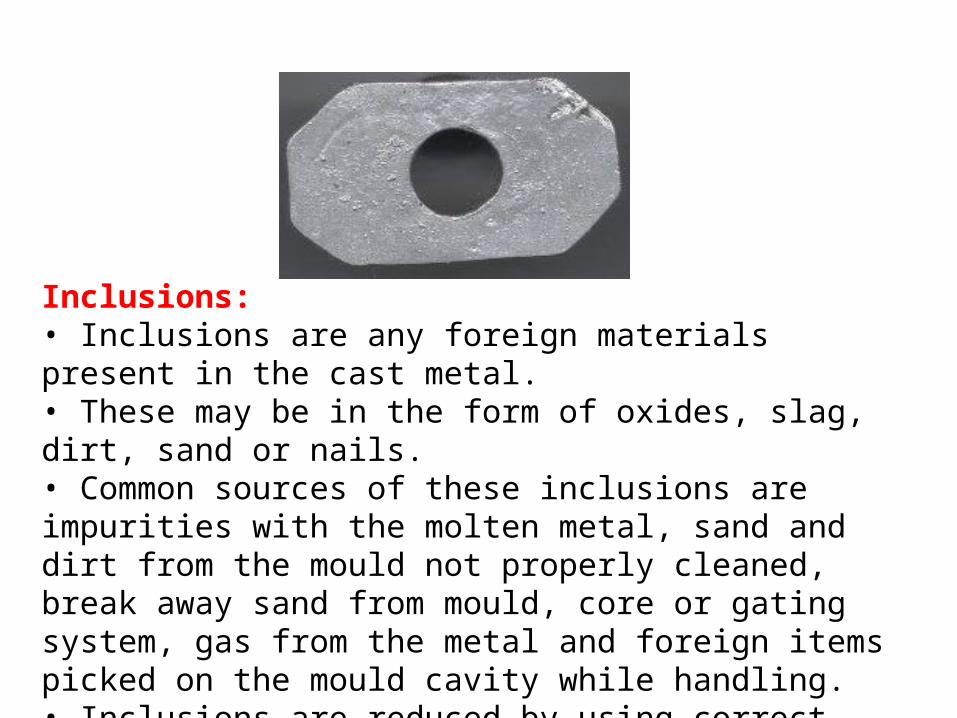
Inclusions:• Inclusions are any foreign materials present in the cast metal.• These may be in the form of oxides, slag, dirt, sand or nails.• Common sources of these inclusions are impurities with the molten metal, sand and dirt from the mould not properly cleaned, break away sand from mould, core or gating system, gas from the metal and foreign items picked on the mould cavity while handling.• Inclusions are reduced by using correct grade of moulding sand and proper skimming to remove impurities.

Cuts and Washes:• Cuts and washes are caused by erosion of mould and core surfaces by the metal flowing in the mould cavity.• These defects are avoided by proper ramming, having sand of required strength and controlling the turbulence during pouring.
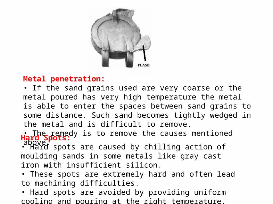
Metal penetration:• If the sand grains used are very coarse or the metal poured has very high temperature the metal is able to enter the spaces between sand grains to some distance. Such sand becomes tightly wedged in the metal and is difficult to remove.• The remedy is to remove the causes mentioned above.
Hard Spots:• Hard spots are caused by chilling action of moulding sands in some metals like gray cast iron with insufficient silicon.• These spots are extremely hard and often lead to machining difficulties.• Hard spots are avoided by providing uniform cooling and pouring at the right temperature.

Scabs:• Scabs are rough, irregular projections on surface of castings containing embedded sand.• Scabs occur when a portion on the face of mould or core lifts and metal flows underneath in a thin layer.• They are caused by using too fine sand grains or using sand of low permeability or moisture content.• They may also be caused by uneven mould ramming or by intense local overheating.• Scabs can be reduced by mixing additives like sea coal, wood flour or dextrin in the sand, providing uniform ramming and pouring with correct velocity.

Hot tears:• Hot tears are ragged irregular internal or external cracks occurring immediately after the metal have solidified.• Hot tears occur on poorly designed castings having abrupt section changes or having no proper fillets or corner radii. Wrongly placed chills.• Improper placement of gates and risers or incorrect pouring temperatures can also produce hot tears.• Hot tears are also caused by poor collapsibility of cores.• If the core does not collapse when the casting is contracting over it stresses will be set up in the casting leading to its failure.• Hot tears can be eliminated by improved design, proper directional solidification, and uniform rate of cooling, correct pouring temperature and control of mould hardness.

Shrinkage Faults:• Shrinkage faults are faults caused by improper directional solidifications, poor gating and risering design and inadequate feeding.• Solidification leads to volumetric contraction which must be compensated by feeding. If this compensation is inadequate either surface shrinkage or internal shrinkage defects are produced making the casting weaker.• Shrinkage faults can be reduced by providing proper gating system, pouring at correct temperature and taking care of directional solidification.
Sand Casting Defects:• Production of castings involves a large number of steps including casting design, pattern making, moulding, melting, pouring, shake out, fettling, inspection and finishing.• It is not uncommon for one or more of these steps to be performed unsatisfactorily due to use of defective material or equipment, carelessness of the operator or lack of skill.• Such unsatisfactory operations result in a defective casting which may be rejected at the final stage.

Hot Chamber Die Casting
Machine
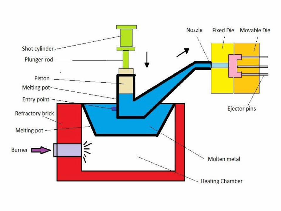

-It is also called a gooseneck machine because of the shape.-In this machine the melting pot, usually made of cast iron, is a part of the machine. -The gooseneck containing a cylinder and metal passage way is kept immersed in the metal pot. -The plunger in the gooseneck cylinder is actuated either hydraulically or pneumatically. -In operation the plunger is withdrawn letting the liquid metal into the gooseneck cylinder through the port provided.-When the die halves are closed and ready for casting the plunger forces the liquid metal entrapped in the cylinder into the die through the gooseneck passage and a nozzle. -After a predetermined time interval the plunger is retracted allowing the liquid metal in the gooseneck channel and nozzle to fall back into cylinder.

The die halves are opened and the solidified casting is ejected from the die. Hot chamber machines are designed to operate almost automatically and fast. A press button operation will make the machine go through a complete cycle of activities including closing the die halves, forcing the metal into the die, holding the pressure for a predetermined time, withdrawing the plunger, opening the die, ejecting the casting and stop ready for the next cycle. The operator then removes the casting, inspects the dies, gives spray lubrication to the dies and starts the next cycle. Metal injection speeds and pressures can be controlled to suit different metals and castings.
Since the melting pot plunger and cylinder of a hot chamber die casting machine are made of cast iron and cast iron reacts with metals like aluminium at elevated temperatures, only low melting-point metals can be cast by this method. There is also a limit on the maximum pressure which can be applied. Hot chamber machines are mostly operated below 14 kPa. Alloys of lead, tin and zinc are the most common metals cast by this process.

Cold chamber die casting machine:


The metal in this case is melted in a separate furnace and the required quantity of metal is ladled to the machine. A plunger operated hydraulically forces the metal into the die. Injection pressures of 28 kPa to 250 kPa are possible in cold chamber machines. The machine is semiautomatic in that after the metal is ladled into the cold chamber the rest of the operation is automatic. Hot chamber machines are made in capacities varying from 0.25 to 7.5 MN and cold chamber ones from 1 to 10 MN.