cassette feeding unit-ad2 - canon...
TRANSCRIPT

54321
Cassette Feeding Unit-AD2
Service Manual
September 17, 2012Revision 0

Contents0 Safety Precautions
Notes Before it Works Serving ---------------------------------------------0-4
1 SpecificationsSpecification --------------------------------------------------------------------1-2Specifications ----------------------------------------------------------------------- 1-2Specifications -------------------------------------------------------------------------------- 1-2
Names of Parts --------------------------------------------------------------------- 1-2External View -------------------------------------------------------------------------------- 1-2Cross-Section View ------------------------------------------------------------------------ 1-2
2 TechnologyFunction -------------------------------------------------------------------------2-2BasicConfiguration ---------------------------------------------------------------- 2-2
Sensor / Solenoid --------------------------------------------------------------------------- 2-2Pickup/Feed System -------------------------------------------------------------- 2-3
Overview -------------------------------------------------------------------------------------- 2-3Sequence ------------------------------------------------------------------------------------- 2-3Paper Size Detection ---------------------------------------------------------------------- 2-4Paper level sensor-------------------------------------------------------------------------- 2-7
JAM Detection ---------------------------------------------------------------------- 2-8Delay JAM ------------------------------------------------------------------------------------ 2-8Stationary JAM ------------------------------------------------------------------------------ 2-8Power ON JAM ------------------------------------------------------------------------------ 2-8Door open JAM ------------------------------------------------------------------------------ 2-8
Power supply ------------------------------------------------------------------------ 2-9Power connection with each option ---------------------------------------------------- 2-9
3 Parts Replacement ProcedureParts Replacement -----------------------------------------------------------3-2
Remove from the host machine ------------------------------------------------ 3-2
Removing the Cassette Feed Roller ------------------------------------------ 3-3Removing the Separation Roller ----------------------------------------------- 3-4Removing the Pickup Roller ----------------------------------------------------- 3-4Removing the Pickup Assembly Idler Gear --------------------------------- 3-5Removing the Cassette 3 Pickup Unit ---------------------------------------- 3-5Removing the Cassette Size Detection Unit -------------------------------- 3-7Removing the Pickup Motor ----------------------------------------------------- 3-8Removing the Pedestal Controll PCB ---------------------------------------- 3-9Removing the Pedestal Right Cover ------------------------------------------ 3-9
4 MaintenanceMaintenance --------------------------------------------------------------------4-2
Periodical maintenance ---------------------------------------------------------- 4-2Periodically replacement parts ---------------------------------------------------------- 4-2Consumables -------------------------------------------------------------------------------- 4-2
Adjustment --------------------------------------------------------------------------- 4-2Margin Adjustment ------------------------------------------------------------------------- 4-2PartsConfiguration/Role ------------------------------------------------------- 4-4PartsConfiguration/Role ---------------------------------------------------------------- 4-4
5 InstallationHow to check this Installation procedure --------------------------------5-2
When using the parts included in the package -------------------------------------- 5-2Symbols in the illustration ---------------------------------------------------------------- 5-2
Checking the Contents ------------------------------------------------------5-2Check Items when Turning OFF the Main Power ---------------------5-3Installation Outline Drawing ------------------------------------------------5-3Unpacking the Equipment --------------------------------------------------5-3Installation Procedure -------------------------------------------------------5-5Cassette Settings -------------------------------------------------------------5-9Adjustment -------------------------------------------------------------------- 5-10
Margin Adjustment (First side; Mechanical Adjsutment) -------------------------5-10Margin Adjustment (Second side) -----------------------------------------------------5-12
6 AppendixService Tools --------------------------------------------------------------------- II

Special Tools --------------------------------------------------------------------------- IIGeneral Circuit Diagram -------------------------------------------------------III
General Circuit Diagram (1/3) ---------------------------------------------------- IIIGeneral Circuit Diagram(2/3) ----------------------------------------------------- IVGeneral Circuit Diagram(3/3) ------------------------------------------------------V

Safety Precautions ■Notes Before it Works Serving

0-5
0-5
Notes Before it Works Serving
Caution
Atservicing,besuretoturnoffthepowersourceaccordingtothespecifiedstepsanddisconnect the power plug.
Caution
Do not turn off the power switch (of the host machine) when downloading is under way.
Turning off the main power switch while downloading is under way can disable the machine.

1
1 Specifications
Specifications ■Specifications ■Names of Parts

1
11-2
1-2
Specifications>Specification>NamesofParts>Cross-SectionView
Specifications>Specification>NamesofParts>Cross-SectionView
Specification
Specifications ■ Specifications
Item Specification Remarks
Paper storage method Front loading method
Pickup method Separation retard method
Paper stack capacity 550sheets (80g/m2 paper),650sheets (64g/m2 paper)
Cassette 2
Paper feed reference Center reference
Paper Type Plain paper, Thick paper, Transparency film
Paper size Standard (universal) A3,B4,A4,B5, LDR,LGL,LTR,A4R,B5R,LTRR, A5R,EXE,STMTR,12”x18”,8K,16K,16KR
Paper grammage 52 to 220g/m2
Paper size switch Size auto detection
Control Panel None (Use the key on the host machine)
Display None (Use the key on the host machine)
Environmental measure Heater for paper humidity adjustment Cassette heater is available as an option
Power supply No Option power supply of the host machine
Size 620(W) - 700(D) - 248(H) [mm]
Weight 27.5kg
Max. power consumption 100WT-1-1
Names of Parts ■ External View
External Cover
[1] Left cover [6] Right lower cover
[2] Upper tray cover [7] Right rear cover
[3] Lower tray cover [8] Rear cover
[4] Right front cover [9] Connector cover
[5] Pedestal right cover
Upper tray cover
Lower tray cover
Left cover Connector cover
Rear cover
Right rear cover
Right front cover
Right lower cover
Pedestal right cover
■ Cross-Section View
Lifter
Lifter
Pickup Roller 3
Pickup Roller 4
Feed Roller 3
Separation Roller 3
Vertical path Roller 3
Feed Roller 4
Separation Roller 4
Vertical path Roller 4
F-1-1
F-1-2
F-1-3
2
2 Technology
Technology ■BasicConfiguration ■Pickup/Feed System ■JAM Detection ■Power supply

2
22-2
2-2
Technology>Function>BasicConfiguration>Sensor/Solenoid
Technology>Function>BasicConfiguration>Sensor/Solenoid
Function
BasicConfiguration ■ Sensor / Solenoid
Pedestal right cover sensor(PS1)
Cassette heater(H1)
Pedestal controllerPCB(UN1)
Cassette 3 pickup motor(M1)Cassette 3 pickup motor(M2)
Cassette 4 sizeswitch B(SW4)
Cassette 4 sizeswitch A(SW3)
Cassette 3 sizeswitch B(SW2)
Cassette 3 sizeswitch A(SW1)
Cassette 3 Retry sensor(PS8)
Cassette 4 Retry sensor(PS9)
Cassette 4paper presence sensor(PS3)Cassette 4
paper level sensor A(PS6)
Cassette 4paper level sensor B(PS7)
Cassette 3paper level sensorA(PS4)
Cassette 3paper level sensor B(PS5)
Cassette 3paper presence sensor(PS2)
Cassette 4pickup solenoid(SL2)
Cassette 3pickup solenoid(SL1)
F-2-1

2
22-3
2-3
Technology>Function>Pickup/FeedSystem>Sequence
Technology>Function>Pickup/FeedSystem>Sequence
Pickup/Feed System ■ Overview
Papers in the cassette are lifted up with the Lifter Plate. At pickup, the Pickup Roller picks up a paper by coming down and contact with paper surface. The Pickup Roller comes down when the Pickup Solenoide turns ON. A paper picked up by the Pickup Roller is fed to the feed path with the Separation Roller, and then, is fed to the Registration Roller with the Vertical Path Roller. The Vertical Path Roller, Pickup Roller, Feed Roller and Separation Roller are driven by the Cassette Pickup Motor.
SL1 M1
SL2 M2
Lifter
Lifter
Pickup Roller 3
Pickup Roller 4
Feed Roller 3
Separation Roller 3
Vertical path Roller 3
Feed Roller 4
Separation Roller 4
Vertical path Roller 4
F-2-2
■ Sequence
Printstart
Cassette 3 pickup motor(M1)Cassette 3 pickupsolenoid (SL1)Cassette 3 pre-registrationsensor (PS8)
Registration sensor(PS33)Fixing motor(M21)Fixing inlet sensor(PS34)Inner delivery sensor(PS37)Fixing delivery motor(M22)
*1 *3*2
0.8sec
A
*1 : Slow up pickup
*3 : Registration*2 : Pre-registration
: Cassette 3 pickup motor speed up
Cassette 2 pre-registrationsensor(PS56)Vertical path sensor(UN53)Registration motor(M19)
Cas
sette
pede
stal
Con
nect
ion
devi
ce
F-2-3

2
22-4
2-4
Technology>Function>Pickup/FeedSystem>PaperSizeDetection
Technology>Function>Pickup/FeedSystem>PaperSizeDetection
■ Paper Size Detection At the cassette pickup assembly, since the feed speed is increased, detection cannot catch up with it. Thus, delay and stationary jam detection are not executed at the Cassette 1 Pre-Registration Sensor. Instead of it, the Vertical Path Sensor executes the delay and stationary jam detection. Since the residual jam should be detected on each cassette, the Cassette 1 Pre-Registration Sensor detects it. Because the Vertical Path Sensor is too close and it is unnecessary to execute detection, the Vertical Path Sensor does not execute residual jam detection.
Cassette 3 size switch B[SW2]
Cassette 4 size switch B[SW4]
Cassette 3 size switch A [SW1]
Cassette 4 size switch A[SW3]
F-2-4
Cassette size switch A
Cassette size switch B
Side guide plate
Rear guide plate
Rear detection rink
Detection dial
Detection dialCassette 2 size switch B
F-2-5

2
22-5
2-5
Technology>Function>Pickup/FeedSystem>PaperSizeDetection
Technology>Function>Pickup/FeedSystem>PaperSizeDetection
Width detection Length detectionWidth Length 1 2 3 4 1 2 3 4
B5 257.0 182.0 0 ON ON 0 0 0 0 0 EXEC 267.0 184.0 0 ON ON 0 0 0 0 0 16K 270.0 195.0 0 ON ON 0 ON 0 0 0 A5-R 148.5 210.0 ON 0 ON 0 ON ON 0 0 A4 297.0 210.0 0 ON 0 0 ON ON 0 0 STMT-R 139.7 215.9 ON 0 ON 0 ON ON 0 0 LTR 279.4 215.9 0 ON ON 0 ON ON 0 0 B5-R 182.0 257.0 ON 0 ON 0 0 ON ON ON LTR-R 215.9 279.4 0 0 ON 0 ON 0 0 ON A4-R 210.0 297.0 0 0 ON 0 0 ON ON 0 LGL 215.9 355.6 0 0 ON 0 ON ON 0 ON B4 257.0 364.0 0 ON ON 0 ON ON ON 0 8K 270.0 390.0 0 ON ON 0 ON ON ON ON A3 297.0 420.0 0 ON 0 0 0 0 ON ON LDR 279.4 431.8 0 ON ON 0 0 0 ON ON 12x18 304.8 457.2 0 ON 0 0 0 0 0 ON
Also, the cassette presence is detected when the size switch is pushed. (If no switch is pushed, it is determined as no cassette.))
● Separation paper listIt is recommended to separate the following paper depending on the paper status (especially moisture absorption) and paper trimming state when setting the paper.This “separation” can avoid troubles.
Paper type Basis weight/name etc Main areaCarbonless paper Overall -Transparency Overall -Labels Overall -Tub paper Overall -Pre-punched paper Overall -OK Prince Joshitsu Especially thin paper, 52 gsm etc. JPNCanon Europe Canon Recycled 80 (Vision Classic White)
Overall EUR
Canon Europe Canon High Grade (Mondi Business Paper)
Especially heavy paper 220/250 gsm etc. EUR
CanonDigitalOfficeColour(StoraEnso MultiCopy Special Colour Laser)
Especially heavy paper 160 gsm etc. EUR
T-2-1
T-2-2
● .Method of Setting 8K and 16K (Chinese Paper)1)SettheoriginaldetectionsizetoABconfiguration.r(Lv.1)COPIER>OPTION>FNC-SW>MODEL-SZ=0
2) Enable detection and display of Chinese paper (K size paper: 8K and 16K).(Lv.2)COPIER>OPTION>FNC-SW>KSIZE-SW=1
3) Change the setting of Cassette 1 from EXEC to 16K.(Lv.2)COPIER>OPTION>CST>CST-K-SW=1
4)(Lv.2)COPIER>OPTION>FNC-SW>MODELSZ2=0.5) Turn OFF and then ON the main power.

2
22-6
2-6
Technology>Function>Pickup/FeedSystem>PaperSizeDetection
Technology>Function>Pickup/FeedSystem>PaperSizeDetection
● Method of Setting Special Paper• Service modeCOPIER>OPTION>CST>CSTX-UY>SettingnumberX:Cassettenumber,Y:Sizecategory(X:1to4,Y:1to4)
Size categorySize category Size
U1 FLSC, A-FLS, OFI, E-OFI, A-LTRR, A-LGL, G-LGL, A-OFI, M-OFI, FA4U2 K-LGLR, G-LTRRU3 K-LGL, A-LTR, G-LTRU4 B-OFI
Setting No. Size22 K-LGL23 K-LGLR24 FLSC25 A-FLS26 OFI27 E-OFI28 B-OFI29 A-LTR30 A-LTRR31 G-LTR32 G-LTRR33 A-LGL34 G-LGL36 A-OFI37 M-OFI42 FA4
Example: When setting G-LTR to Cassette 2COPIER>OPTION>CST>CST2-U3>3
T-2-3
T-2-4
● Cassette Heater ControlThis heater is controlled to keep constant internal temperature. Basically, when the Environment Switch is ON, the heater is ON regardless of ON/OFF of the main power except for during printing. (Excluding the case where the internal temperature is high)

2
22-7
2-7
Technology>Function>Pickup/FeedSystem>Paperlevelsensor
Technology>Function>Pickup/FeedSystem>Paperlevelsensor
■ Paper level sensorPaper level in a cassette is detected with the sensor indicated below.
Cassette 3 Cassette 4Paper level sensor A PS4 PS6
Paper level sensor B PS5 PS7
Paper sensor PS2 PS3
Flag
Cassette paper sensor
Cassette paperlevel sensor A
Cassette paperlevel sensor B
Paper sensor flag
Lifter latch
Lifter gear
Tray
T-2-5
F-2-6
OFFOFF
OFFON
ONON
If the paper is full
Cassette paper level sensor B
Cassette paper level sensor B
Cassette paper level sensor B
Cassette paper level sensor A
Cassette paper level sensor A
Cassette paper level sensor A
If the paper is approx. half
If the paper is a little
If the paper is absent
Paper
Paper
Paper
Cassette paper Presence sensor
Paper tray Fulg
F-2-7

2
22-8
2-8
Technology>Function>JAMDetection>DooropenJAM
Technology>Function>JAMDetection>DooropenJAM
Paper level sensor A
Paper level sensor B
Paperl sensor
Paper level Display
OFF OFF OFF 100% to 50%
ON OFF OFF 50% to 50 sheets
ON ON OFF 50 sheet or less
--- --- ON no paper
JAM Detection ■ Delay JAM
Incasethattheleadingedgeofpaperdoesnotreachtothesensorwithinthespecifiedtimeafter the speed of Cassette 3 and 4 Pickup Motor decreases to half.
Jam check
Sensor / PS8 / PS9
Pick-up motor
normal
[1]:Provision feed time
error
Start kye ONor
Print start
[1] [1]
INTR / PRINT
:Motor speed up
Cassette Motor SensorCassette 3 Cassette 4 pickup motor
(M1)Cassette 3 pre-registration sensor
(PS8)
Cassette 4 Cassette 4 pickup motor (M2)
Cassette 4 pre-registration sensor (PS9)
F-2-8
T-2-6
F-2-9
T-2-7
■ Stationary JAMIncasethatthecorrespondingsensorisnotturnedONwithinthespecifiedtimeafteritisturned ON.
Jam check
Sensor / PS8 / PS9
(L = Paper length feed range A = Provision feed range)
L + A L + A
INTR / PRINT
Start kye ONor
Print start
normal error
Sensor
Cassette 3 pre-registration sensor (PS8)
Cassette 4 pre-registration sensor (PS9)
■ Power ON JAMBefore starting the warm-up rotation at power ON, check that no paper is at the sensor indicated below.
Sensor
Cassette 3 pre-registration sensor (PS8)
Cassette 4 pre-registration sensor (PS9)
■ Door open JAMWhen it is detected that the door is opened during copy and printing.
Sensor
Pedestal right cover sensor(PS1)
F-2-10
T-2-8
T-2-9
T-2-10

2
22-9
2-9
Technology>Function>Powersupply>Powerconnectionwitheachoption
Technology>Function>Powersupply>Powerconnectionwitheachoption
Power supply ■ Power connection with each option
Indicating the power supply path between the Printer and Option.
Reader / ADF Unit
Paper DeckUnit-B1
Booklet Finisher-C1
Cassette Feeding Unit-AD1
Built-in wiring
Connector inside the cover is used for the connection with the printer.F-2-11
When power is turned ON, the connected equipment supplies 24VDC and 5VDC to the Pedestal Controller PCB. 24VDC is used to drive the motor and solenoid. 5VDC is used to drive the sensor and IC. In addition, 24VDC and 5VDC are supplied to the Paper Deck Unit B1 via the equipment.
Pedestal controller PCBConnect in device
+3.3VIC
+5U
5V
24V
24V
IC7
24V
Regulator
SensorFU4
Motor,Solenoid
Paper deckUnit B1
Controllerpower supplyPCB
DCControllerPCB
Controllerpower supplyPCB
F-2-12

3
3 Parts Replacement Procedure
Parts Replacement Procedure
■Remove from the host machine ■Removing the Cassette Feed Roller ■Removing the Separation Roller ■Removing the Pickup Roller ■Removing the Pickup Assembly Idler Gear
■Removing the Cassette 3 Pickup Unit ■Removing the Cassette Size Detection Unit ■Removing the Pickup Motor ■Removing the Pedestal Controll PCB ■Removing the Pedestal Right Cover

3
33-2
3-2
PartsReplacementProcedure>PartsReplacement>Removefromthehostmachine
PartsReplacementProcedure>PartsReplacement>Removefromthehostmachine
Parts Replacement
Remove from the host machineBefore removing the host machine• Remove the Connecter Cover
How to remove1) Remove the 5 harness from the guides
x6
Guides
F-3-1
F-3-2
2) Remove the 5 connecters
x5
Connectors
Connectors
3) Remove the Connecting Fixture• 1 screw
F-3-3
F-3-4

3
33-3
3-3
PartsReplacementProcedure>PartsReplacement>RemovingtheCassetteFeedRoller
PartsReplacementProcedure>PartsReplacement>RemovingtheCassetteFeedRoller
Note:
• Weight of the machine is 175kg at maximum, so when lifting this machine, be sure to work in a group of 4 or more people to lift horizontally.
• Be careful since the center of gravity is put toward the rear side when lifting the machine.
F-3-5
4) Install the cassette 3 and cassette 4.
Removing the Cassette Feed RollerBefore removing the Cassette Feed Roller• Remove the Cassette• Open the Pedestal right cover
MEMO: This procedure describes the removing steps of cassette 1 Feed Roller. Go through the same procedure for the Feed Roller of cassette 3 and cassette 4.
Note:
Do not touch the surface of Pickup Roller, Feed Roller and the Separation Roller.
How to remove1) Remove the Cassette Feed Roller.• 1 tab
F-3-6

3
33-4
3-4
PartsReplacementProcedure>PartsReplacement>RemovingthePickupRoller
PartsReplacementProcedure>PartsReplacement>RemovingthePickupRoller
Removing the Separation RollerBefore removing the Separation Roller• Remove the Cassette• Open the Pedestal right cover
How to remove
MEMO: This procedure describes the removing steps of cassette 1 Separetion Roller. Go through the same procedure for the Separetion Roller of cassette 3 and cassette 4.
Note:
Do not touch the surface of Pickup Roller, Feed Roller and the Separation Roller.
1) Removing the Separation Roller• 1 tab
F-3-7
Removing the Pickup RollerBefore removing the Cassette Pickup Roller• Remove the Cassette• Open the pedestal right cover
How to remove
MEMO: This procedure describes the removing steps of cassette 1 Pickup Roller. Go through the same procedure for the Pickup Roller of cassette 3 and cassette 4.
Note:
Do not touch the surface of Pickup Roller, Feed Roller and the Separation Roller.
1) Removing the Pickup Roller• 1 pin• 1 tab
F-3-8
3
33-5
3-5
PartsReplacementProcedure>PartsReplacement>RemovingtheCassette3PickupUnit
PartsReplacementProcedure>PartsReplacement>RemovingtheCassette3PickupUnit
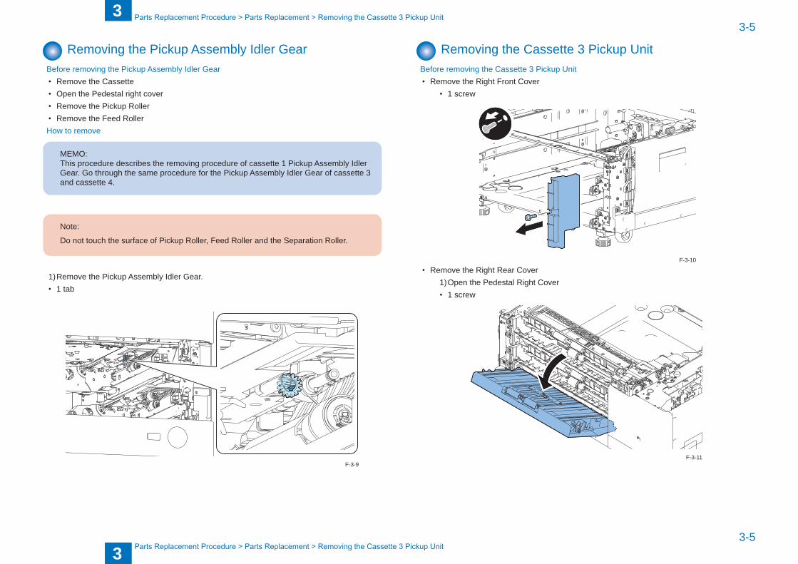
Removing the Pickup Assembly Idler GearBefore removing the Pickup Assembly Idler Gear• Remove the Cassette• Open the Pedestal right cover• Remove the Pickup Roller• Remove the Feed RollerHow to remove
MEMO: This procedure describes the removing procedure of cassette 1 Pickup Assembly Idler Gear. Go through the same procedure for the Pickup Assembly Idler Gear of cassette 3 and cassette 4.
Note:
Do not touch the surface of Pickup Roller, Feed Roller and the Separation Roller.
1) Remove the Pickup Assembly Idler Gear.• 1 tab
F-3-9
Removing the Cassette 3 Pickup UnitBefore removing the Cassette 3 Pickup Unit• Remove the Right Front Cover
• 1 screw
• Remove the Right Rear Cover1) Open the Pedestal Right Cover• 1 screw
F-3-10
F-3-11

3
33-6
3-6
PartsReplacementProcedure>PartsReplacement>RemovingtheCassette3PickupUnit
PartsReplacementProcedure>PartsReplacement>RemovingtheCassette3PickupUnit
2) Remove the Right Rear Cover• 1 screw
How to remove
MEMO:This procedure describes the removing procedure of Cassette 3 Pickup Assembly. Go through the same procedure for the Cassette 4 Pickup Assembly.
F-3-12
MEMO:When connecting from host machine, remove the cassette 1 and cassette 2.1) Pull out cassette 1 and cassette 2 and remove the Right Front over 3.• 1 screw
Right front cover 3
2)Open the Pedestal Right Cover and remove the Right Lower Sub Cover 2.
x2
Clows
Right Pedestal Cover
Right Lower Sub Cover 2
F-3-13
F-3-14

3
33-7
3-7
PartsReplacementProcedure>PartsReplacement>RemovingtheCassetteSizeDetectionUnit
PartsReplacementProcedure>PartsReplacement>RemovingtheCassetteSizeDetectionUnit
1) Remove the Sensor Unit.• 1 screw• 1 connector• 1 harness guide
Connector
Harness Guide
Sensor Unit
2)Remove the cassette 3 Pickup Unit• 4 screws
x4
F-3-15
F-3-16
Removing the Cassette Size Detection UnitBefore removing the Cassette Size Detection Unit• Remove the Right Front Cover• Remove the Right Rear Cover• Remove the Cassette Pickup Unit
How to remove
MEMO:This procedure describes the removing steps of Cassette 3 Size Detection Unit. Go through the same procedure for Cassette 4 Size Detection Unit.
1) Remove the Cassette 3 Size Detection Unit• 1 connector• 1 wire saddle• 2 screws
x2Connector Wire Saddle
Cassette 3 Size Detection Unit
F-3-17

3
33-8
3-8
PartsReplacementProcedure>PartsReplacement>RemovingthePickupMotor
PartsReplacementProcedure>PartsReplacement>RemovingthePickupMotor
Removing the Pickup MotorBefore removing the Pickup Motor• Remove the Connector Cover• Remove 5 connectors• Remove Rear Cover
• 4 screws• 2 hooks
x4
Hooks Rear Cover
How to remove
MEMO:This procedure describes the removing step of cassette 3 Pickup motor. Go through the same procedure for the Pickup motor of cassette 4.
F-3-18
1) Remove the upper pickup motor.• 1 connector• 3 screws
x3
F-3-19

3
33-9
3-9
PartsReplacementProcedure>PartsReplacement>RemovingthePedestalRightCover
PartsReplacementProcedure>PartsReplacement>RemovingthePedestalRightCover
Removing the Pedestal Controll PCBBefore removing the Pedestal Controll PCB• remove the Connector Cover• Remove the 5 connectors• Remove the Rear Cover
How to remove1)Remove the Pedestal Controll PCB• 7 connectors• 4 screws
x4
x7
F-3-20
Removing the Pedestal Right CoverBefore removing the Pedestal Right Cover• Open the right pedestal cover
How to remove1) Lift up lower guide and remove the arm
2) Fit the D-cut and remove the right pedestal cover
D-cut
F-3-21
F-3-22

4
4 Maintenance
Maintenance ■Periodical maintenance ■Adjustment ■PartsConfiguration/Role

4
44-2
4-2
Maintenance>Maintenance>Adjustment>MarginAdjustment
Maintenance>Maintenance>Adjustment>MarginAdjustment
Maintenance
Periodical maintenance ■ Periodically replacement parts
● Periodically Replaced PartsN / A
■ Consumables
● ConsumablesParts Name Parts
NumberNum Interval Remarks
Feeding roller FC6-7083 2 150k
Separation roller FC6-6661 2 150k
Pickup idler gear FU0-0043 2 150k For China only Flying Paper
T-4-1
Adjustment ■ Margin Adjustment
● First side; Mechanical Adjsutment1) Make copies using the Cassette 3 and 4, and check that the left edge margin is 2.5±1.5mm.
Feed direction of paper
L1
image
MEMO:Adjsutment method is same for both the Cassette 3 and 4.
2) Pull out the cassette. 3) Check the 2 scale positions on the adjusting plates.
F-4-1
F-4-2

4
44-3
4-3
Maintenance>Maintenance>Adjustment>MarginAdjustment
Maintenance>Maintenance>Adjustment>MarginAdjustment
4)Loosenthe3fixingscrews.
5) Move the adjusting plates back and forth by referring the scale checked in the step 2. As moving the adjusting plate toward the rear by 1 scale, the left edge margin becomes 1mm smaller.
MEMO:When moving the scale, be sure that the amount of the value to be moved are the same for the 2 points.
6)Tightenthefixingscrew.
F-4-3
F-4-4
7) Return the cassette to its original position.
MEMO:When the cassette positions are uneven due to the mechanical adjustment, adjust them by loosening the screw at left side.
8) Make copies using the Cassette 3 and 4, and check that the left edge margin is 2.5±1.5mm.F-4-5

4
44-4
4-4
Maintenance>Maintenance>PartsConfiguration/Role>PartsConfiguration/Role
Maintenance>Maintenance>PartsConfiguration/Role>PartsConfiguration/Role
● Second side1) Make 2-sided copies using the Cassette 4, and check that the left edge margin is
2.5±2.0mm.
L1
image
Feed direction of paper
2) As for nonstandard, change the left edge margin adjustment value for the second side of the 2-sided copy from the Cassette 3.As making the following selection: ServiceMode>COPIER>ADJUST>FEED-ADJ>ADJ-C3REandset1valuelarger,theleft edge margin becomes 0.1mm smaller.
3) Enter the value set to the left edge margin adjustment value for the second side of the 2-sided copy from the Cassette 3 as the side registration adjustment value for the second side of the 2-sided copy from the Cassette 4.ServiceMode>COPIER>ADJUST>FEED-ADJ>ADJ-C4RE
4) To enable the setting value, turn off/on the Main Power Supply of the equipment.5) Make 2-sided copies using the Cassette 4, and check that the left edge margin is
2.5±2.0mm.6) As for nonstandard, change the left edge margin adjustment value for the second side of
the 2-sided copy from the Cassette 4.As making the following selection: ServiceMode>COPIER>ADJUST>FEED-ADJ>ADJ-C4REand set 1 value larger, the left edge margin becomes 0.1mm smaller.
7) Enter the new adjustment value on the Service Label.ADJ-C3READJ-C4RE
8) Get out from the service mode.
F-4-6
PartsConfiguration/Role ■ PartsConfiguration/Role
Mark Name Part No. RoleFUNCTION >PART-
CHK
Pedestal controller PCB
M1 Cassette 3 pickup motor FK2-7326 Drive the pickup unit 3
J3006
M2 Cassette 4 pickup motor FK2-7326 Drive the pickup unit 4
J3007
PS4 Cassette 3 paper level sensor A
WG8-5848 Detects the cassette 3 paper level
J3004
PS5 Cassette 3 paper level sensor B
WG8-5848 Detects the cassette 3 paper level
J3004
PS8 Cassette 3 pre-registration sensor
WG8-5848 Detects the cassette 3 pre-registration
J3004
PS2 Cassette 3 paper sensor WG8-5848 Detects whether paper is loaded in the cassette 3
J3004
PS6 Cassette 4 paper level sensor A
WG8-5848 Detects the cassette 4 paper level
J3004
PS7 Cassette 4 paper level sensor B
WG8-5848 Detects the cassette 4 paper level
J3004
PS9 Cassette 4 pre-registration sensor
WG8-5848 Detects the cassette 4 pre-registration
J3004
PS3 Cassette 4 paper sensor WG8-5848 Detects whether paper is loaded in the cassette 4
J3004
PS1 Pedestal right cover sensor
WG8-5848 Detects the right cover open
J3004
SL1 Cassette 3 pickup solenoid
FK2-0408 controll the cassette 3 pickup timing
J3004
SL2 Cassette 4 pickup solenoid
FK1-0408 controll the cassette 4 pickup timing
J3004
SW1 Cassette 3 size switch A WC2-5680 Detects the cassette 3 paper size
J3005
SW2 Cassette 3 size switch B WC2-5680 Detects the cassette 3 paper size
J3005
SW3 Cassette 4 size switch A WC2-5680 Detects the cassette 4 paper size
J3005
SW4 Cassette 4 size switch B WC2-5680 Detects the cassette 4 paper size
J3005
H1 Cassette heater FK2-7322/7323
UN1 Pedestal controller PCB FM4-1202 Controll the cassette pedestal
T-4-2

4
44-5
4-5
Maintenance>Maintenance>PartsConfiguration/Role>PartsConfiguration/Role
Maintenance>Maintenance>PartsConfiguration/Role>PartsConfiguration/Role
Pedestal right cover sensor(PS1)
Cassette heater(H1)
Pedestal controllerPCB(UN1)
Cassette 3 pickup motor(M1)Cassette 3 pickup motor(M2)
Cassette 4 sizeswitch A(SW3)
Cassette 4 sizeswitch B(SW4)
Cassette 3 sizeswitch A(SW1)
Cassette 3 sizeswitch B(SW2)
Cassette 3 Pre-registration sensor(PS8)
Cassette 4 Pre-registration sensor(PS9)
Cassette 4paper presence sensor(PS3)Cassette 4
paper level sensor A(PS6)
Cassette 4paper level sensor B(PS7)
Cassette 3paper level sensorA(PS4)
Cassette 3paper level sensor B(PS5)
Cassette 3paper presence sensor(PS2)
Cassette 4pickup solenoid(SL2)
Cassette 3pickup solenoid(SL1)
F-4-7
5
5 Installation
Installation ■How to check this Installation procedure ■Checking the Contents ■Installation ■Adjustment

5
55-2
5-2
Installation>CheckingtheContents
Installation>CheckingtheContents
How to check this Installation procedure ■When using the parts included in the package
A symbol is described on the illustration in the case of using the parts included in the package of this product.
Packaged Item
■ Symbols in the illustrationThe frequently-performed operations are described with symbols in this procedure.
Connector
Disconnect
Screw
Tighten Remove Connect Secure Free
Harness
PushInsert Plug in Turn on
Sound CheckCheck Visual Check
Claw
Remove
Checking instruction
F-5-1
F-5-2
Checking the Contents
[1] Cassette Pedestal X 1 [2] Connecting Fixture X 1
[3] Screw (RS Tightening; M3X8.5) X 1 [4] Size Plate X 2
[5] Connector Cover X 1
F-5-3

5
55-3
5-3
Installation>UnpackingtheEquipment
Installation>UnpackingtheEquipment
Check Items when Turning OFF the Main PowerCheck that the main power is OFF.1) Turning off the Main Power Supply Switch of the Host Machine.2) Check that the display on the Control Panel and the Main Power Supply Lamp are turned
off before disconnecting the outlet.
Installation Outline Drawing
F-5-4
Unpacking the Equipment
1) Remove the container box.
CAUTION:
To prevent a fall, be sure not to lift this equipment while it is still in the plastic bag.
2) Open the plastic, remove the 2 pads and a piece of Cardboard by lifting rear of the equipment, and move the plastic toward the pads at front.
Plastic
Pad
Pad
Cardboard
F-5-5
F-5-6

5
55-4
5-4
Installation>UnpackingtheEquipment
Installation>UnpackingtheEquipment
3) Remove the plastic and the remaining 2 pads by lifting the equipment.
Plastic Pad
Pad
4) Lift the equipment and bring it down from pallet.
F-5-7
F-5-8
5) Removealltapesaffixedonoutsideoftheequipment.
NOTE:Tapesaffixedoninsideofthecassettewillberemovedinalaterstep.
F-5-9

5
55-5
5-5
Installation>InstallationProcedure
Installation>InstallationProcedure
Installation Procedure
1) Open the Right Lower Cover.
CAUTION:
Be sure to open the Right Lower Cover when placing the Host Machine; otherwise, it may be damaged.
2) IfthereistheRightLowerSubcover1oftheHostMachine,removeitbyusingflatblade.
NOTE:When installing the host machine at the same time, skip this step because the Right Lower Sub Cover is packed with the host machine.
Right Lower Sub-cover 1
Flat-blade screwdriver
F-5-10
F-5-11
screwdriver.
CAUTION:
• The host machine weighs maximum 134kg. It is recommended to lift it with 4 people or more. However, if there is a standard to handle a heavy load in each sales company, follow it for operation. Also, make sure to lift the machine with keeping it level at operation.
• Because the gravity center is in the rear, lift with care.
F-5-12

5
55-6
5-6
Installation>InstallationProcedure
Installation>InstallationProcedure
3) Hold the 4 handles on the Host Machine, and place it on the equipment by aligning corners at front of the Host Machine and the equipment.
CAUTION:
When placing the Host Machine on the equipment, be sure to move the Host Machine parallelandfitthe2positioningpinsontheuppersurfaceoftheequipmentintotheholes on the base plate of the Host Machine.
Positioning Pins
4) Press the Cassette Release Button and remove the Cassette 2 and 3.
Button
F-5-13
F-5-14
5) Attachtheconnectingfixture.• 1 screw (RS Tightening; M3x8.5)
CAUTION:
Whenattachingtheconnectingfixture,besuretheattachingdirection.
F-5-15
F-5-16
5
55-7
5-7
Installation>InstallationProcedure
Installation>InstallationProcedure
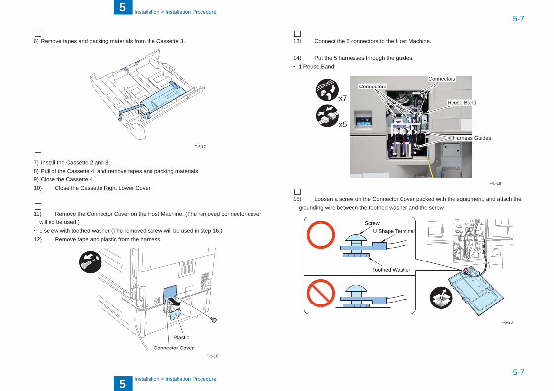
6) Remove tapes and packing materials from the Cassette 3.
7) Install the Cassette 2 and 3. 8) Pull of the Cassette 4, and remove tapes and packing materials. 9) Close the Cassette 4. 10) Close the Cassette Right Lower Cover.
11) Remove the Connector Cover on the Host Machine. (The removed connector cover will no be used.)
• 1 screw with toothed washer (The removed screw will be used in step 16.) 12) Remove tape and plastic from the harness.
Connector Cover
Plastic
F-5-17
F-5-18
13) Connect the 5 connectors to the Host Machine.
14) Put the 5 harnesses through the guides.• 1 Reuse Band
Harness Guides
ConnectorsConnectors
x7 Reuse Band
x5
15) Loosen a screw on the Connector Cover packed with the equipment, and attach the grounding wire between the toothed washer and the screw.
ScrewU Shape Terminal
Toothed Washer
F-5-19
F-5-20

5
55-8
5-8
Installation>InstallationProcedure
Installation>InstallationProcedure
16) Install the Connector Cover.• 1 screw with toothed washer (Use the screw removed in the step 11.)
17) Secure the equipment in place with the 4 adjusters.
NOTE:Securing of the adjuster is not earthquake resistant.
F-5-21
F-5-22
NOTE:• When installing the host machine simultaneously, be sure to follow "Unpacking and
Installation" in the Installation Procedure Manual.• When installing this equipment later, be sure to follow the following procedure.
18) Connect the Power Supply Plug of the Host Machine to the outlet. 19) Turn on the Main Power Supply Switch of the Host Machine.

5
55-9
5-9
Installation>CassetteSettings
Installation>CassetteSettings
Cassette Settings
1) Press the Cassette Release Button, and pull out the Cassette 3 and 4 toward the front.
Button
2) HoldtheSideGuidePlateLever,andadjustittothepredefinedsize.Atthattime,movetheSideGuidePlatebyreferringthesizeindex(label)ofthesheetsizetobeset,andfititto the slot.
3) HoldtheTrailEdgeGuidePlateLever,andadjustittothepredefinedsize.Atthattime,move the Trail Edge Guide Plate by referring the size index (label) of the sheet size be set, andfitittotheslot.
Side Guide Plate Lever
Side Guide Plate
Trail Edge Guide Plate
Trail Edge Guide Plate Lever
F-5-23
F-5-24
4) Set papers. 5) Open the cover from which the Size Plate is pushed in.
Paper
Cover
6) Cut 2 places of the Size Plate with nippers.
Cut
F-5-25
F-5-26

5
55-10
5-10
Installation>Adjustment
Installation>Adjustment
7) Set the Size Plate in accordance with the size being set. (Lump the Size Plates not in use together and store them at the rear.)
8) Close the cover from which the Size Plate is pushed in, and install the cassette. 9) Set the Cassette 4 in the same way.
NOTE:Paper size settings are automatically recognized.
F-5-27
Adjustment
NOTE:The second side of the 2-sided copy mentioned later means the second side in the image formation order. With this equipment, the second side in the image formation order at the time of 2-sided copy/printisequivalenttothefirstsideoftheoriginal.
■ Margin Adjustment (First side; Mechanical Adjsutment)
1) Make copies using the Cassette 3 and 4, and check that the left edge margin is 2.5±1.5mm.
Feed direction of paper
L1
image
<InCaseofNonstandard>
NOTE:Adjsutment method is same for both the Cassette 3 and 4.
2) Pull out the cassette. 3) Check the 2 scale positions on the adjusting plates.
F-5-28
F-5-29

5
55-11
5-11
Installation>Adjustment
Installation>Adjustment
4)Loosenthe3fixingscrews.
5) Move the adjusting plates back and forth by referring the scale checked in the step 2. As moving the adjusting plate toward the rear by 1 scale, the left edge margin becomes 1mm smaller.
NOTE:When moving the scale, be sure that the amount of the value to be moved are the same for the 2 points.
F-5-30
6)Tightenthefixingscrew.7) Return the cassette to its original position.
NOTE:When the cassette positions are uneven due to the mechanical adjustment, adjust them by loosening the screw at left side.
8) Make copies using the Cassette 3 and 4, and check that the left edge margin is 2.5±1.5mm.
F-5-31
F-5-32

5
55-12
5-12
Installation>Adjustment
Installation>Adjustment
■ Margin Adjustment (Second side)
1) Make 2-sided copies using the Cassette 4, and check that the left edge margin is 2.5±2.0mm.
L1
image
Feed direction of paper
2) As for nonstandard, change the left edge margin adjustment value for the second side of the 2-sided copy from the Cassette 3.Asmakingthefollowingselection:ServiceMode>COPIER>ADJUST>FEED-ADJ>ADJ-C3RE and set 1 value larger, the left edge margin becomes 0.1mm smaller.
3) Enter the value set to the left edge margin adjustment value for the second side of the 2-sided copy from the Cassette 3 as the side registration adjustment value for the second side of the 2-sided copy from the Cassette 4.ServiceMode>COPIER>ADJUST>FEED-ADJ>ADJ-C4RE
4) To enable the setting value, turn off/on the Main Power Supply of the equipment.5) Make 2-sided copies using the Cassette 4, and check that the left edge margin is
2.5±2.0mm.6) As for nonstandard, change the left edge margin adjustment value for the second side of
the 2-sided copy from the Cassette 4.Asmakingthefollowingselection:ServiceMode>COPIER>ADJUST>FEED-ADJ>ADJ-C4RE and set 1 value larger, the left edge margin becomes 0.1mm smaller.
7) Enter the new adjustment value on the Service Label.ADJ-C3READJ-C4RE
8) Get out from the service mode.
F-5-33

Appendix ■Service Tools ■General Circuit Diagram (1/3) ■General Circuit Diagram(2/3) ■General Circuit Diagram(3/3)

II
II
Appendix>ServiceTools>SpecialTools
Appendix>ServiceTools>SpecialTools
Service Tools
Special ToolsIn addition to the standard tools set, the following special tools are required when servicing the machine:
Tool name Tool No. Ctgr Appearance RemarksDigital multimeter FY9-2002 A Used as a probe extension when making electrical checks.
Reference: Category A: Must be kept by each service engineer.B:Mustbekeptbyeachgroupofaboutfiveengineers.C: Must be kept by each warkshop
T-6-1

III
III
Appendix>GeneralCircuitD
iagram
>GeneralCircuitD
iagram
(1/3)
Appendix>GeneralCircuitD
iagram
>GeneralCircuitD
iagram
(1/3)
General Circuit Diagram
General Circuit Diagram (1/3)
12345678910
12345678910
F
E
D
C
B
A
F
E
D
C
B
A
P.1
SL SL
+5V
CS
T3_P
AP
ER
_SN
S
GN
D
GN
D
CS
T3_L
EV
EL_
A_S
NS
+5V
GN
D
CS
T3_L
EV
EL_
B_S
NS
+5V
GN
D
CS
T3_R
ETR
Y_S
NS
+5V
+24V
CS
T3_P
ICK
UP
_SL
GN
D
CS
T4_P
AP
ER
_SN
S
+5V
GN
D
CS
T4_L
EV
EL_
A_S
NS
GN
D
+5V
CS
T4_L
EV
EL_
B_S
NS
+5V
GN
D
CS
T4_R
ETR
Y_S
NS
+5V
CS
T4_P
ICK
UP
_SL
+24V G
ND
PE
DE
_DO
OR
_SN
S
+5V
J104DH
1 2 3 4 5 6 7 8 9 10 11 12 13 14 15 16 17 18 19 20 21 22 23 24 25 26 27 28 29 30 31
J3004
1413121110982 3 4 5 6 71
J2L
J2LH
2890111213141 345 167J2D
123J3
123
J105
1413121110982 3 4 5 6 71
J1L
J1LH
2890111213141 345 167J1D
3 2 1
Cassette 3 Cassette 4
1 2J104L
12
J104D
1 2J109L
12
J109D
3 2 1 1 21 2
J109DH
3 2 1
123
J106
3 2 1 3 2 1
123
J103
123
J101
3 2 1
123
J100
3 2 1 3 2 1 3 2 1
123
J102
123
J107
123
J108
Pedestal right cover sensorPS1
Pedestal controller PCBUN1
Cassette 4retry sensor
PS9Cassette 4
pickup solenoid
SL3Cassette 3
pickupsolenoid
SL2Cassette 4paper levelsensor B
PS7Cassette 4paper levelsensor A
PS6Cassette 4
paper sensor
PS3Cassette 3retry sensor
PS8Cassette 3paper levelsensor B
PS5Cassette 3paper levelsensor A
PS4Cassette 3
paper sensor
PS2
F-6-1

IV
IV
Appendix>GeneralCircuitD
iagram
>GeneralCircuitD
iagram
(2/3)
Appendix>GeneralCircuitD
iagram
>GeneralCircuitD
iagram
(2/3)
General Circuit Diagram(2/3)
12345678910
12345678910
F
E
D
C
B
A
F
E
D
C
B
A
P.2
M M
CS
T3_S
IZE
_7
CS
T3_S
IZE
_6
CS
T3_S
IZE
_4
CS
T3_S
IZE
_3
CS
T3_S
IZE
_2
CS
T3_S
IZE
_1
CS
T3_S
IZE
_5
CS
T3_S
IZE
_0
CS
T4_S
IZE
_7
CS
T4_S
IZE
_1
CS
T4_S
IZE
_2
CS
T4_S
IZE
_3
CS
T4_S
IZE
_4
CS
T_S
IZE
_PW
R_O
N
CS
T_S
IZE
_PW
R_O
N
CS
T4_S
IZE
_6
CS
T_S
IZE
_PW
R_O
N
CS
T4_S
IZE
_5
CS
T_S
IZE
_PW
R_O
N
CS
T3_A
CS
T3_A
*
CS
T3_B
CS
T3_B
*
CS
T4_A
CS
T4_A
*
CS
T4_B
CS
T4_B
*
CS
T4_S
IZE
_0
N.C
.
1 2 3 4
J3006
1110982 3 4 5 6 71
J8L
J8LH
2890111 345 167J8D
2890111 345 167J5D
12345J10
12345J9
12345J7
12345J6
J5LH1110982 3 4 5 6 71
J5L
1 2 3 4 5 6 7 8 9 10 12 13 14 15 16 17 18 19 20 1211
J3005
4321
J3007
6 5 4 3 2 1
J12123456
J11
654321654321
Pedestal controller PCBUN1
Cassette 3 pickup motorM1
Cassette 4size switch A
SW3Cassette 4
size switch B
SW4Cassette 3
size switch A
SW1Cassette 3
size switch B
SW2
Cassette 4 pickup motorM2
F-6-2

V
V
Appendix>GeneralCircuitD
iagram
>GeneralCircuitD
iagram
(3/3)
Appendix>GeneralCircuitD
iagram
>GeneralCircuitD
iagram
(3/3)
General Circuit Diagram(3/3)
12345678910
12345678910
F
E
D
C
B
A
F
E
D
C
B
A
P.3
GN
D
RXO
UTE
ND
TXTD
ATA
TXR
OAD
CLK
GN
D
RXE
ND
RXD
ATA
PE
DE
_DE
TEC
T1
+5V
PE
DE
1_E
X_M
2S
PE
DE
1_E
X_S
2M
GN
D
GN
D
GN
D
GN
D
GN
D
PE
DE
1_E
X_C
LK
PE
DE
1_C
ST1
M_C
LK
PE
DE
1_C
ST2
M_C
LK
PE
DE
1_R
ES
ET*
PE
DE
1_R
EA
DY
GN
D 5V24
V
2 31
J1001
SOLD1
MT3
SOLD2SOLD3
1 32
J1012
MT4
3 4 5 61 2
J1008
3 4 5 61 2J23F
2 3 4 5 61J23M
21
J3101
21J25F
761 543 514131211101982
J3102
289011121314151 345 167J26
J1000MB_BUS[0:8]
J1000MB
41 2 3
J1000M
12345678J1002
841 2 3 5 6 7
2121
To Paper Deck Unit-B1 To Relay PCB To DC controller PCB
Pedestal controller PCBUN1
Cassette heaterH1
AC DRIVER PCB
F-6-3