cased hole electromechanical cable - camesa inc
TRANSCRIPT

Introduction
Strength
Electrical Power
Electrical Communication
Temperature Rating
Special Cable Problems
Cable Service
Reversing a Line
Attenuation VS FreqGraph
Electrical FaultLocation
Derivation of FaultDetection Formula
"CASED HOLE" Electromechanical Cable
Introduction
The electromechanical cable used in oilfield wireline service operations must perform four -basic functions.
1. Strength Member: The cable must have sufficient strength to carry an instrument package to any depth. In most cases the weight of a cable itself is the greatest part of the load.
2. Electrical Power: The conductors in the cable must be adequate to supply electrical power from the truck to the instrumentation at the bottom of the cable.
3. Electrical Communication: The electrical conductors must be suitable to transmit the electrical information generated by the down hole instruments to the computer or recorder in the truck.
4. Depth Measurements: The only method of measuring the depth, at which the down hole instruments are located (and the corresponding geological beds of interest), is to measure the length of cable that has been put into the bore-hole. Without accurate depth information the instrument data is of little value.
Throughout this school we will be referring to the Camesa type 1N32PP cable as an example. Many wire-line service companies, throughout the world use this cable for cased-hole logging operations.
Previous Page | Print Page
Camesa, Inc · 1615 Spur 529 · P.O. Box 1048 · Rosenberg, Texas 77471Phone: (281) 342-4494 · Fax: (281) 342-0531

Introduction
Strength
Electrical Power
Electrical Communication
Temperature Rating
Special Cable Problems
Cable Service
Reversing a Line
Attenuation VS FreqGraph
Electrical FaultLocation
Derivation of FaultDetection Formula
Cased Hole
STRENGTH
Cable armor wire is classified as "galvanized extra-improved plow steel". It has a tensil range of from 270 to 300 thousand PSI.
1. Guaranteed Minimum breaking strength: The manufacturers rated minimum breaking strength applies to a new cable, pulled straight with no rotation allowed. For the 1N32PP type cable this rated strength; is 11,000 Ibs. Actual factory break tests performed on each new cable typically result in values closer to 11,500 Ibs.
2. The actual breaking: Strength for a cable may be less than the guaranteed minimum breaking strength for the following reasons:
a. Wearb. Corrosionc. Bendingd. Fatiguee. Torquef. Rotation
g. Physical damageh. Defective tension device
3. Weak Spots: Cables do not have "weak spots". If they break at tensions below the guaranteed minimum breaking strength, it is for one of the above reasons. Individual wire breaks can be the result of weak point or defect in the wire, but these occur less than one in every 2 million feet of wire. The probability of all the wires in a cable having a defect at the same point in the lenght is virtually impossible. Individual wire breaks can occur for all of the above reasons and in addition:
a. Faults or inclusions in the steel structureb. Butt weldsc. Damage during manufacturing respooling
4. Field Failures: Experience over the years clearly indicates
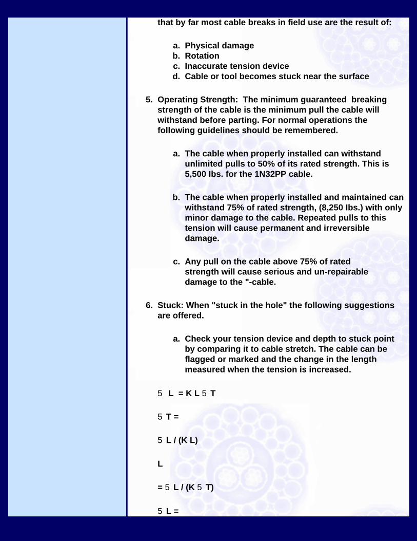
that by far most cable breaks in field use are the result of:
a. Physical damageb. Rotationc. Inaccurate tension deviced. Cable or tool becomes stuck near the surface
5. Operating Strength: The minimum guaranteed breaking strength of the cable is the minimum pull the cable will withstand before parting. For normal operations the following guidelines should be remembered.
a. The cable when properly installed can withstand unlimited pulls to 50% of its rated strength. This is 5,500 Ibs. for the 1N32PP cable.
b. The cable when properly installed and maintained can withstand 75% of rated strength, (8,250 Ibs.) with only minor damage to the cable. Repeated pulls to this tension will cause permanent and irreversible damage.
c. Any pull on the cable above 75% of rated strength will cause serious and un-repairable damage to the "-cable.
6. Stuck: When "stuck in the hole" the following suggestions are offered.
a. Check your tension device and depth to stuck point by comparing it to cable stretch. The cable can be flagged or marked and the change in the length measured when the tension is increased.
5 L = K L 5T
5T =
5L / (K L)
L
= 5L / (K 5T)
5L =

change of length
5T =
change in tension
L
= length to stuck point
K = stretch coefficient 1.2 ft/1000ft/1000 lbs.
b. Check all devices the cable physically contacts. Be sure the correct sheave wheel (proper diameter and groove shape) is being used and that trucks and sheave are properly aligned. Any pinching, bending or scraping of the cable can significantly reduce the cable strength.
c. Move your "set-up" distance so that the armor wires are not fatigued by repeated bending in the same area by the sheave wheel or measuring device.
d. Use common sense in "spudding". "Spudding" means using the inertia of the logging instrument to break through a bridge that is blocking the well bore. The cable was designed to work in tension - not compression.
7. Splices: Cased hole cables are sometimes spliced. With regard to cable strength the following points should be remembered.
a. A properly made splice, either shimmed or welded, will develop at least 90% of the strength of an unspliced cable in a straight pull.
b. Splices will not tolerate spudding. Drastic reductions of strength of a splice can occur if it is put in compression.
c. Splices fatigue rapidly in bending around sheave wheels and measuring devices. The

smaller the sheave diameter, the more rapid the deterioration of the splice.
8. Torsion and Rotation. All logging and perforating generate a specific torque when subjected to a load. When permitted, the cable will rotate many revolutions. For the 1N32PP cable, the approximate values are:
a. Torsion - 1.3 ft.-lbs/1000 Ibs tension changeb. Rotation - 5 revolutions/1000 ft/1000 Ib tension
change
When the cable is first put into use it will "spin-out" in response to the tension profile it experiences. That is, the cable will rotate in the direction of the outer armor layer winding. Once the cable has "spun-out", there will be a torque generated and tendencies for the cable to rotate only when there is a change in the tension profile.
The cable experiences a change in tension profile every time it goes into and comes out of the well as a result of the frictional drag on the tool and cable. If the cable were lowered and pulled out at an uniformly slow speed there would be virtually zero frictional drag. Under those conditions a seasoned cable would have no tendency to rotate. Under practical operating conditions the tension going into the hole is several hundred or even several thousand pounds less than the tension coming out. This results in significant torque and rotation in the cable during every round trip into and out of a well.
There in no limit to the speed at which the cable can be spooled except as how if affects the tension in the cable and the resulting torque and rotation.
To avoid any cable problems resulting from cable torque, the tension at any given depth should never be less than 1/2 of the tension going into the hole at that same depth coming out of the hole. When the tension drops to 1/3 there is loss of contact between the inner and out armor layers, in this condition, the cable can accumulate wellbore material between the armor layers, develop "high wire", or "bird caging" of the arm can occur.

Previous Page | Print Page
Camesa, Inc · 1615 Spur 529 · P.O. Box 1048 · Rosenberg, Texas 77471Phone: (281) 342-4494 · Fax: (281) 342-0531

Introduction
Strength
Electrical Power
Electrical Communication
Temperature Rating
Special Cable Problems
Cable Service
Reversing a Line
Attenuation VS FreqGraph
Electrical FaultLocation
Derivation of FaultDetection Formula
Cased Hole
Electrical Power
One of the main functions of the EM Cable is to transfer electrical power from surface panels to down-hole logging instruments. In order to determine which is the best cable for the job the following issues should be considered.
1. Voltage Rating: The voltage rating of a new 1N32PP cable is 1500 volts D.C. All new cables are tested at the factory at twice the rated maximum voltage rating for 5 minutes before they leave the factory. The specified maximum voltage is a conservative rating. The reason for this conservative rating is to take into account some of the stresses that the cable can be exposed to during normal operations. These stresses include splices, physical abuse the cable will normally experience in field use, and the effects of temperature and pressure.
The voltage ratings are not reduced by temperature within the temperature rating of the cable. Since the voltage ratings are conservative, the ratings can be applied to used Camesa cables, provided that splices are done carefully and physical abuse to the cable is not excessive.
2. Power Handling: The combination of cable maximum voltage rating and the conductor electrical resistance are the factors that limit the conductor current.
Another factor, which needs to be considered, is the heat generated by high current applications. Passing several amps through the conductor for several hours, with a portion of the cable tightly wound on the drum, can cause a significant amount of heat to build up. With the cable tightly wound on the drum the conductor can not dissipate the heat and the cable on the drum acts as a big heating coil. Sustained high currents in such situations, can cause sufficient heating to melt the plastic insulation around the conductor.
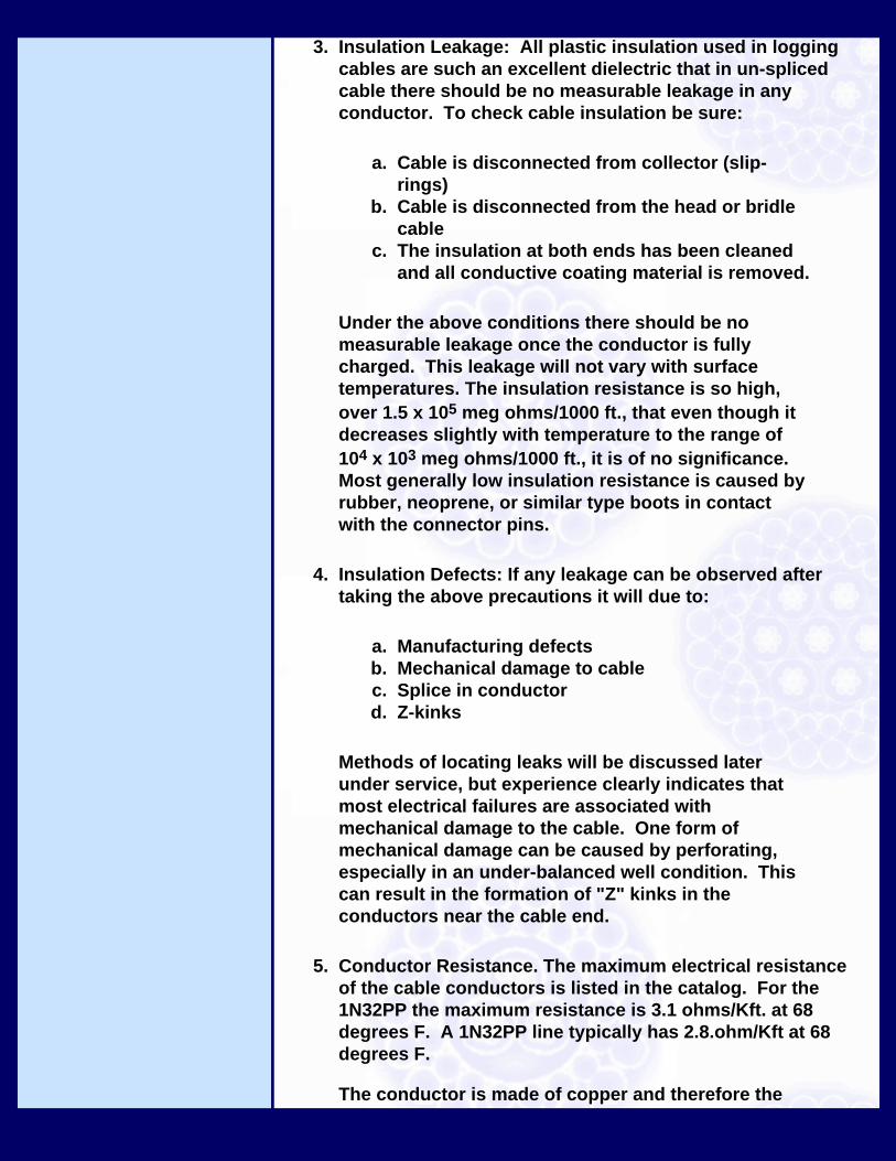
3. Insulation Leakage: All plastic insulation used in logging cables are such an excellent dielectric that in un-spliced cable there should be no measurable leakage in any conductor. To check cable insulation be sure:
a. Cable is disconnected from collector (slip-rings)
b. Cable is disconnected from the head or bridle cable
c. The insulation at both ends has been cleaned and all conductive coating material is removed.
Under the above conditions there should be no measurable leakage once the conductor is fully charged. This leakage will not vary with surface temperatures. The insulation resistance is so high, over 1.5 x 10⁵ meg ohms/1000 ft., that even though it decreases slightly with temperature to the range of 104 x 103 meg ohms/1000 ft., it is of no significance. Most generally low insulation resistance is caused by rubber, neoprene, or similar type boots in contact with the connector pins.
4. Insulation Defects: If any leakage can be observed after taking the above precautions it will due to:
a. Manufacturing defectsb. Mechanical damage to cablec. Splice in conductord. Z-kinks
Methods of locating leaks will be discussed later under service, but experience clearly indicates that most electrical failures are associated with mechanical damage to the cable. One form of mechanical damage can be caused by perforating, especially in an under-balanced well condition. This can result in the formation of "Z" kinks in the conductors near the cable end.
5. Conductor Resistance. The maximum electrical resistance of the cable conductors is listed in the catalog. For the 1N32PP the maximum resistance is 3.1 ohms/Kft. at 68 degrees F. A 1N32PP line typically has 2.8.ohm/Kft at 68 degrees F.
The conductor is made of copper and therefore the

resistance of the conductor varies with temperature as
For T in degrees Centigrade
RT2 = RT1(.9214 + .00393 T2)(.9214 + .00393 T1)
For T in degrees Fahrenheit
RT2 = RT1(.8515 + .00218 T2)(.8515 + .00218 T1)
RT = Resistance at temperature
T =Temperature at which RT was measured
More specifically for the 1M32PP cable with a typical resistance of 2.8 ohm/Kft. at 68 degrees F.
For T in degrees Centigrade
RT = (2.58 + .011 T) ohm/1000 ft.
For T in degrees Fahrenheit
RT = (2.38 + .00611 T) ohm/1000 ft.
At 274 degrees C (526° F) the resistance of copper is double its value at 20 degrees C (68° F).
This demonstrates the significant effect of temperature on conductor resistance. Of course, as the resistance increases, the ability of the cable to transmit power and return signals decreases!
As a cable is lowered into the hole the total conductor resistance for the 1N32PP cable will be
For T in degrees Centigrade
RL = (2.58 + .011 Ts)L + [2.58 + .0055(TB - Ts) ] D ohms

For T in degrees Fahrenheit
RL = (2.38 + .00611 Ts )L + [2.38 + .00305( TB - Ts )] D ohms
where
RL = total conductor resistance - ohms
L = total length of cable on truck winch - units of 1000ft.
TS = surface temperature
D = depth of tool - units of 1000 ft
TB = bottom hole temperature
Previous Page | Print Page
Camesa, Inc · 1615 Spur 529 · P.O. Box 1048 · Rosenberg, Texas 77471Phone: (281) 342-4494 · Fax: (281) 342-0531

Introduction
Strength
Electrical Power
Electrical Communication
Temperature Rating
Special Cable Problems
Cable Service
Reversing a Line
Attenuation VS FreqGraph
Electrical FaultLocation
Derivation of FaultDetection Formula
Cased Hole
ELECTRICAL COMMUNICATION
A variety of signals are transmitted from down hole instruments to the surface by means of the cable conductors and armor. These signals vary in frequency from DC to 60 - 100 khz. At 100 khz the attenuation of a 1N32PP cable is in the range of 0.68 db/kft @ 10khz and 2.28 db/kft at 60 hz. A plot of attenuation versus frequency is shown in the attached graph.
1. Capacitance and Resistance. The cable is basically a R-C network for most of the frequencies used on the cable. Therefore to improve signal transmission, it is desirable to reduce capacity and resistance. Unfortunately as the conductor diameter is increased to reduce electrical resistance, the electrical capacity of conductor (with respect to armor) increases.
For the 1N32PP cable the D/d ratio of 2.1 results in a nominal characteristic impedance in the range of 30 to 50 ohms for the frequencies normally used. The characteristic impedance varies with frequency starting at the DC value and. asymptotically approaching a high frequency value.
2. Dielectric Materials. Signal attenuation in different dielectric materials varies due to the differences in dielectric constants.
a. Poly Propylene 2.3b. Tefzel 2.6c. FEP Teflon 2.1d. PFA Teflon 2.1
The dielectric losses for all of these materials is so low over the frequencies involved that it can be ignored.
3. Temperature Effects. For all practical purposes the dielectric
constant of all the plastic materials is unchanged up to the maximum operating temperature. On the other hand the resistance of the copper conductors goes up rapidly and therefore so does the attenuation of the cable. At 526° F. the resistance of copper is double its value at 68° F. Therefore that portion of a cable at 526 degree F. will have double the attenuation of that portion of the same cable at 68 degree F.
Previous Page | Print Page
Camesa, Inc · 1615 Spur 529 · P.O. Box 1048 · Rosenberg, Texas 77471Phone: (281) 342-4494 · Fax: (281) 342-0531

Introduction
Strength
Electrical Power
Electrical Communication
Temperature Rating
Special Cable Problems
Cable Service
Reversing a Line
Attenuation VS FreqGraph
Electrical FaultLocation
Derivation of FaultDetection Formula
Cased Hole
TEMPERATURE RATING
The temperature ratings given in the cable catalog are the temperatures at which the cable will perform satisfactorily under normal operating conditions.
1. Temperature gradually increases with depth.2. The principal load carried by the cable will be the cable weight.
Temperature ratings, are absolute maximums for the insulations used in the cable. Routine operation or operation for extended periods of time at the absolute maximum temperature ratings are not recommended.
Cables can fail at temperatures less than rated due to:
1. Excessive tension2. Low inner armor coverage.3. Corrosive materials in the bore-hole in contact with conductor insulation.
Previous Page | Print Page
Camesa, Inc · 1615 Spur 529 · P.O. Box 1048 · Rosenberg, Texas 77471Phone: (281) 342-4494 · Fax: (281) 342-0531

Introduction
Strength
Electrical Power
Electrical Communication
Temperature Rating
Special Cable Problems
Cable Service
Reversing a Line
Attenuation VS FreqGraph
Electrical FaultLocation
Derivation of FaultDetection Formula
Cased Hole
SPECIAL CABLE PROBLEMS
1. Sour gas2. Acid3. Water and gas in conductors
a. Pull out of cable headb. Cracks in insulationc. Diffusion through insulation
Previous Page | Print Page
Camesa, Inc · 1615 Spur 529 · P.O. Box 1048 · Rosenberg, Texas 77471Phone: (281) 342-4494 · Fax: (281) 342-0531

Introduction
Strength
Electrical Power
Electrical Communication
Temperature Rating
Special Cable Problems
Cable Service
Reversing a Line
Attenuation VS FreqGraph
Electrical FaultLocation
Derivation of FaultDetection Formula
Cased Hole
CABLE SERVICE
1. Proper installation to prevent drum crush2. Loose armor3. Broken armor wire4. Splices5. Corrosion6. Electrical break down
Previous Page | Print Page
Camesa, Inc · 1615 Spur 529 · P.O. Box 1048 · Rosenberg, Texas 77471Phone: (281) 342-4494 · Fax: (281) 342-0531

Introduction
Strength
Electrical Power
Electrical Communication
Temperature Rating
Special Cable Problems
Cable Service
Reversing a Line
Attenuation VS FreqGraph
Electrical FaultLocation
Derivation of FaultDetection Formula
Cased Hole
REVERSING A LINE
There is often a desire to reverse a line or turn it end for end so that the virgin portion of the line can be used. This practice is not recommended for the following reasons:
1. Problems of overlap of new tension-rotation profile with previous tension-rotation profile can result in loose armor or high wires.
2. "Z - kink" formation when the tension is lowered from operational tensions to shipping reel spooling tensions.
3. Corrosion rate accelerated due to used portion of cable not being flexed.
4. Cable weak point no longer guaranteed to be at the cable-head.
5. Potential problems with spooling due to smaller diameter of used section of line.
Previous Page | Print Page
Camesa, Inc · 1615 Spur 529 · P.O. Box 1048 · Rosenberg, Texas 77471Phone: (281) 342-4494 · Fax: (281) 342-0531

Introduction
Strength
Electrical Power
Electrical Communication
Temperature Rating
Special Cable Problems
Cable Service
Reversing a Line
Attenuation VS FreqGraph
Electrical FaultLocation
Derivation of FaultDetection Formula
Cased Hole
ATTENUATION VS. FREQ. 25,000 FT
Previous Page | Print Page
Camesa, Inc · 1615 Spur 529 · P.O. Box 1048 · Rosenberg, Texas 77471Phone: (281) 342-4494 · Fax: (281) 342-0531

Introduction
Strength
Electrical Power
Electrical Communication
Temperature Rating
Special Cable Problems
Cable Service
Reversing a Line
Attenuation VS FreqGraph
Electrical FaultLocation
Derivation of FaultDetection Formula
Cased Hole
Electrical Fault Location
L = Total cable Length (ft.)F = Distance to cable fault from cable head end (ft.)RH = Resitance of conductor to armor from cable head end (ohms)RD = Resistance of conductor to armor from drum end (ohms)RC = Resistance of conductor, end to end (ohms)RF = Resistance of fault (ohms)
Previous Page | Print Page

Camesa, Inc · 1615 Spur 529 · P.O. Box 1048 · Rosenberg, Texas 77471Phone: (281) 342-4494 · Fax: (281) 342-0531

Introduction
Strength
Electrical Power
Electrical Communication
Temperature Rating
Special Cable Problems
Cable Service
Reversing a Line
Attenuation VS FreqGraph
Electrical FaultLocation
Derivation of FaultDetection Formula
Cased Hole
Derivation of Fault Detection Formula
Previous Page | Print Page

Camesa, Inc · 1615 Spur 529 · P.O. Box 1048 · Rosenberg, Texas 77471Phone: (281) 342-4494 · Fax: (281) 342-0531