case study on mp3 format
TRANSCRIPT

8/3/2019 Case Study on Mp3 Format
http://slidepdf.com/reader/full/case-study-on-mp3-format 1/26
System-On Chip Modeling and DesignA case study on MP3 Decoder
Pramod Chandraiah, Hans Gunar Schirner, Nirupama Srinivas and Rainer Doemer
CECS Technical Report 04-17
June 21, 2004
Center for Embedded Computer SystemsUniversity of California, Irvine
Irvine, CA 92697-3425, USA(949) 824-8059
8/3/2019 Case Study on Mp3 Format
http://slidepdf.com/reader/full/case-study-on-mp3-format 2/26
System-On Chip Modeling and DesignA case study on MP3 Decoder
Pramod Chandraiah, Hans Gunar Schirner, Nirupama Srinivas and Rainer Doemer
CECS Technical Report 04-17
June 21, 2004
Center for Embedded Computer SystemsUniversity of California, Irvine
Irvine, CA 92697-3425, USA(949) 824-8059
[email protected] [email protected]
Abstract
This document covers the results from a course project of the graduate class "System-on-Chip
Description and Modeling". It reflects the theoretical knowledge gained during the course lectures as well
as the practical experiences of the course project. The project goal was to take an existing C code of an
audio decoder (MPEG 1 Layer 3), convert the code into a system on a chip specification, and follow thedesign paradigm towards a concrete implementation. The design specification, capturing and synthesis
were performed using the SpecC language and its tools set developed at UC Irvine.

8/3/2019 Case Study on Mp3 Format
http://slidepdf.com/reader/full/case-study-on-mp3-format 3/26
1
ContentsList of Figures................................................................................................................. 21 Abstract................................................................................................................... 3
2 Introduction to SoC Design..................................................................................... 32.1 Challenges of SoC Design ............................................................................... 3
2.2 SoC Specification ............................................................................................ 42.3 SoC Exploration .............................................................................................. 5
3 Design Example...................................................................................................... 73.1 Overview of MPEG-1 Audio Layer 3 .............................................................. 7
3.2 Brief Description of MP3 Decoder .................................................................. 73.3 C implementation of MP3 decoder .................................................................. 9
3.4 Design Constraints .......................................................................................... 94 Specification Model .............................................................................................. 10
4.1 Writing Specification model in SpecC ........................................................... 114.2 Case Study: MP3 Decoder............................................................................. 12
5 Design Space Exploration ..................................................................................... 19
5.1 IP Library:..................................................................................................... 195.2 Exploration 1:................................................................................................ 205.3 Exploration 2:................................................................................................ 21
5.4 Exploration 3:................................................................................................ 226 Implementation ..................................................................................................... 22
7 Conclusion............................................................................................................ 238 References ............................................................................................................ 24

8/3/2019 Case Study on Mp3 Format
http://slidepdf.com/reader/full/case-study-on-mp3-format 4/26
2
List of FiguresFigure 1 Abstraction Levels In SoC Design (Source [2])................................................. 4
Figure 2 SoC Design Methodology (Source [2]).............................................................. 5Figure 3 MPEG 1 Layer 3 Frame Format (Source [3]) .................................................... 7Figure 4 Block Diagram of MP3 Decoder (Source[3]).................................................... 8
Figure 5 Call Graph of major MP3 Decoder Functions................................................... 9Figure 6 Testbench Design............................................................................................ 13
Figure 7 Testbench Design with Communication Channels ........................................... 14Figure 8 Testbench Design Detailed Representation...................................................... 15
Figure 9 Generic Behavior Split .................................................................................... 16Figure 10 Code Profile per Behavior ............................................................................. 17
Figure 11 Distribution of Computation among Behaviors.............................................. 18Figure 12 Total Size of Variables per Behavior ............................................................. 18

8/3/2019 Case Study on Mp3 Format
http://slidepdf.com/reader/full/case-study-on-mp3-format 5/26
3
1 AbstractThis document covers the results from a course project of the graduate class “System-on-
Chip Description and Modeling”. It reflects the theoretical knowledge gained during thecourse lectures as well as the practical experiences of the course project. The project goal
was to take an existing C code of an audio decoder (MPEG 1 Layer 3), convert the code
into a system on a chip specification, and follow the design paradigm towards a concreteimplementation. The design specification, capturing and synthesis were performed usingthe SpecC language and its tools set developed at UC Irvine.
2 Introduction to SoC DesignImprovements in manufacturing capabilities allow placing of a complete embeddedsystem on a single chip. With that it becomes possible to design a system as a mix of
software running on a generic processor and specialized hardware, which performsotherwise expensive computation. This design freedom leads ultimately to highly
specialized chips and cost efficient production. However the newly gained freedom in
design places a burden on the SoC designer. The next paragraphs will introduce thechallenges of system level design, the specification of systems and the design spaceexploration.
2.1 Challenges of SoC Design
The design of a SoC has similar goals as an embedded design. The designed system will
be used in a well-specified environment, and has to fulfill strict requirements. Somerequirements are clearly defined by the application like the functional requirements of an
algorithm, e.g. the decoding of an MPEG 1 Layer 3 data stream, which covers certainquality restrictions. The environment poses other requirements: e.g. minimizing the cost,
footprint, or power consumption. However due to the flexibility of a SoC design,
achieving the set goals, involves analyzing a multi dimensional design space. The degreesof freedom stem from the process element types and characteristics, their allocation, themapping of functional elements to the process elements, their interconnection with busses
and their scheduling.To give another perspective of the design space, it is good to look at the levels of
abstraction. A SoC design has to deal with a wide range: it starts with a functionaldescription on system level, where major function blocks are defined and no timing
information is given. The other end of the spectrum is the result of the design process,where all functionalities described before are mapped to hardware and all hardware is
defined down to the RTL level. At that point in time a cycle accurate model exists, whichis ready for production. Figure 1 depicts the levels of abstraction.

8/3/2019 Case Study on Mp3 Format
http://slidepdf.com/reader/full/case-study-on-mp3-format 6/26
4
Figure 1 Abstraction Levels In SoC Design (Source [2])
The goal of SoC design paradigm is to manage the immense size of design decisions inthe hardware software co-design. This is only possible by following a well-defined flow
of design steps. Those design steps and their associated models will be described in the
next paragraphs.
2.2 SoC Specification
Hardware/Software co-design is an integral aspect of the SoC design. It requires alanguage with is capable of capturing the requirements of an hardware design from wire
allocations do complex timing requirements, as well as the complexities of currentsoftware design. During the lecture different alternatives languages for system level
design were presented: the C++ library extension SystemC [5], some extensions to theUML capturing. The main focus was on the SpecC language, which is an extension of the
ANSI-C language. It uses the ANSI-C for description of software requirements and addsfeatures needed for system design. It allows grouping of functionality to behaviors, which
later can be freely mapped to processing elements. In order to allow this free mapping thecomputation has to be separated from the communication. Therefore communication
between the behaviors is abstractly defined as channels. The channel specificimplementation (e.g. a PCI bus protocol) will be filled in during later refinement stages.
The specification model is free of such implementation detail (and constrain).The SpecC language further introduces many concepts from hardware description
languages like VHDL and Verilog. It introduces the concept of capturing schedulinginformation in the language, such as sequential, parallel and pipelined execution.
The SpecC language very much supports the goals of specification capturing. It allowsdescribing a fully functional model that incorporates design constrains and is testable
against a set of test vectors.The next section describes the exploration and refinement steps to transform the system
specification into a manufacturable description.

8/3/2019 Case Study on Mp3 Format
http://slidepdf.com/reader/full/case-study-on-mp3-format 7/26
5
2.3 SoC Exploration
Together with the SpecC language a design paradigm was introduced, which tries toformalize individual refinements steps and gives the designer guidelines how to handle
efficiently the immense design space. Figure 2 shows an overview of the design flow, it
also indicates the integration of the validation flow. The tool suite provided with theSpecC language closely follows the outlined design flow. The following paragraphs willdescribe the steps of the design flow.
Figure 2 SoC Design Methodology (Source [2])
The SoC design starts with the specification model, which is a purely functional modelfree of any implementation details. It focuses on capturing the algorithmic behavior and
allows a functional validation of the description. The model is untimed and allows onlyfor causal ordering. Once the specification model is finished it will serve as a “golden
model”, to compare to during the design cycle.Architecture information is added during the Architeture refinement. During this step
processing elements are inserted into the system and functional behaviors are mapped tothem. The processing elements can be standard components such as generic processor
cores or DSPs, as well as specific hardware. Parameters, such as clock frequency, of theinserted elements can be adjusted to the application needs. Based on internal statistics,
first estimations about the runtime performance can be made, which gives the designerthe first feedback about the design decisions. Once the architecture refinement is finished,
the architecture model that captures the decisions is created. This model is the first timed
8/3/2019 Case Study on Mp3 Format
http://slidepdf.com/reader/full/case-study-on-mp3-format 8/26
6
model. It takes only computing time into account; all communication between theprocessing elements execute in zero time.
A further step in the refinement, the Scheduling Refinement, is not shown in this graph.This refinement allows the designer to select suitable scheduling mechanisms to its
processing elements. The scheduling capabilities range from a preset static scheduling,
which allows the most predictability, to a priority based dynamic scheduling.The communication refinement allows the user to select busses and protocols. Later theabstract communication channels of the Specification Model can be mapped to physical
busses and protocols. Detailed information about the protocols will be added. Theresulting Communication Model will include specific instructions for the particular bus
type and will be a bus functional model.The last step in the design flow is the synthesis. Here the RTL code for the hardware will
be generated after the RTL component allocation, their functional mapping andscheduling. As a result of the hardware synthesis a cycle accurate of each hardware-
processing element is created. Similar activities take place for the software synthesis.Here specific code for the selected RTOS is created and a target specific assembly code
compiled. The result is a cycle accurate model of each software-processing element,which can be simulated on an instruction set simulator and executed on the target
processor. The combination of both synthesis parts is captured in the Implementationmodel, which gives a cycle accurate description of the system.
This chapter has introduced the theoretical background of system design. It described theindividual models and the refinement steps needed to reach an implementation. The next
chapter will introduce the surrounding information for the practical work on the MP3decoder. It will also derive the design constraints.
8/3/2019 Case Study on Mp3 Format
http://slidepdf.com/reader/full/case-study-on-mp3-format 9/26
7
3 Design Example
3.1 Overview of MPEG-1 Audio Layer 3
Digital compression of audio data is important due to the bandwidth and storage
limitations inherent in networks and computers. Regular algorithms are ineffectivetowards data intensive audio files, MP3 on the other hand provides significant
compression through lossy compression applying the perceptual science of psychoacoustics. The Psycho acoustic model implemented by MP3 algorithm takes advantage of
the fact that the exact input signal does not need to be retained. Since the human ear canonly distinguish a certain amount of detail, it is sufficient that the output signal sounds
identical to the human ears.The course project involves the system specification and design exploration of an MP3
decoder. In the following section the generic structure of an MP3 decoder is presented.
3.2 Brief Description of MP3 Decoder
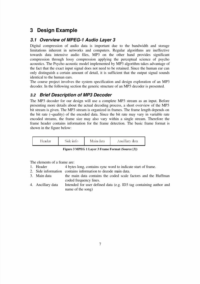
The MP3 decoder for our design will use a complete MP3 stream as an input. Beforepresenting more details about the actual decoding process, a short overview of the MP3
bit stream is given. The MP3 stream is organized in frames. The frame length depends onthe bit rate (~quality) of the encoded data. Since the bit rate may vary in variable rate
encoded streams, the frame size may also vary within a single stream. Therefore theframe header contains information for the frame detection. The basic frame format is
shown in the figure below:
Figure 3 MPEG 1 Layer 3 Frame Format (Source [3])
The elements of a frame are:
1. Header 4 bytes long, contains sync word to indicate start of frame.2. Side information contains information to decode main data.
3. Main data the main data contains the coded scale factors and the Huffmancoded frequency lines.
4. Ancillary data Intended for user defined data (e.g. ID3 tag containing author andname of the song)
8/3/2019 Case Study on Mp3 Format
http://slidepdf.com/reader/full/case-study-on-mp3-format 10/26
8
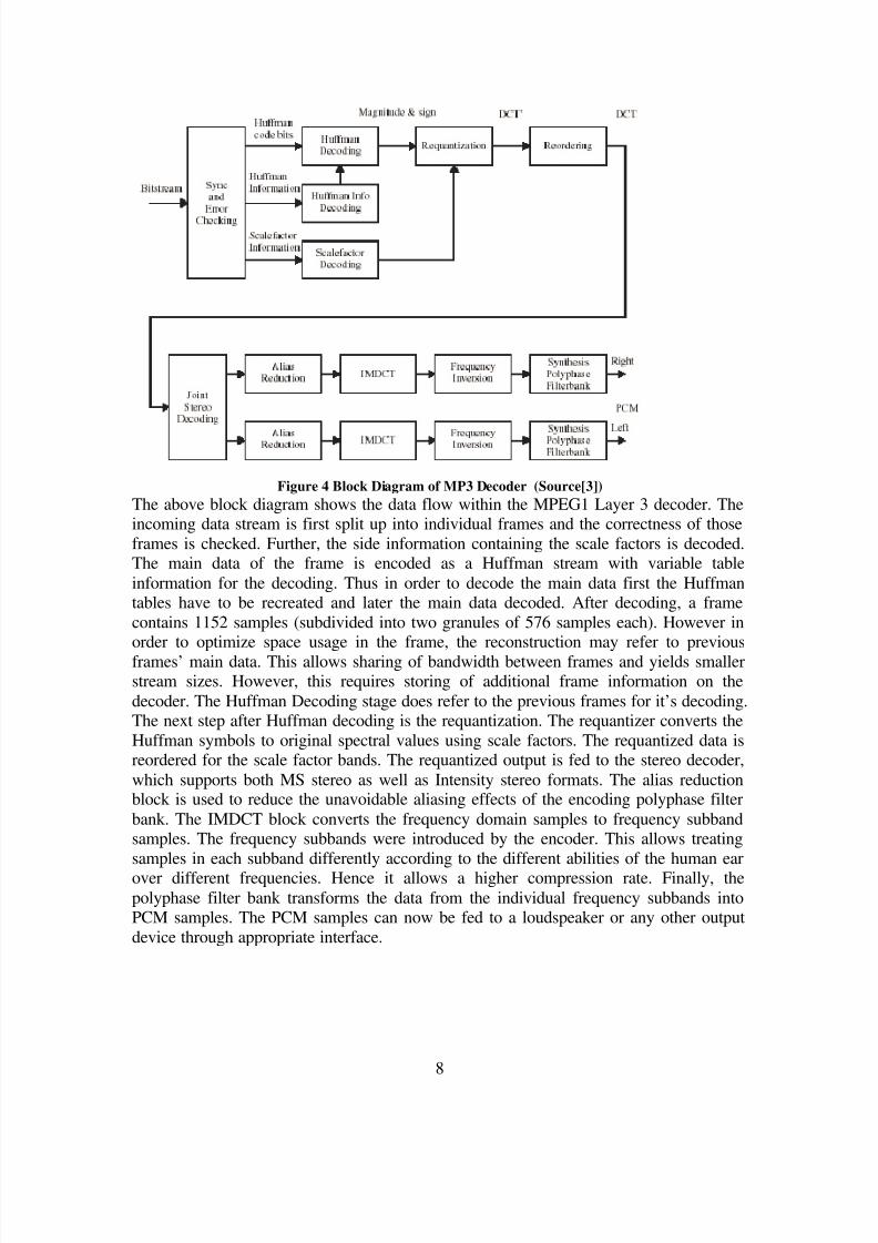
Figure 4 Block Diagram of MP3 Decoder (Source[3])
The above block diagram shows the data flow within the MPEG1 Layer 3 decoder. Theincoming data stream is first split up into individual frames and the correctness of those
frames is checked. Further, the side information containing the scale factors is decoded.The main data of the frame is encoded as a Huffman stream with variable table
information for the decoding. Thus in order to decode the main data first the Huffmantables have to be recreated and later the main data decoded. After decoding, a frame
contains 1152 samples (subdivided into two granules of 576 samples each). However inorder to optimize space usage in the frame, the reconstruction may refer to previous
frames’ main data. This allows sharing of bandwidth between frames and yields smallerstream sizes. However, this requires storing of additional frame information on the
decoder. The Huffman Decoding stage does refer to the previous frames for it’s decoding.The next step after Huffman decoding is the requantization. The requantizer converts the
Huffman symbols to original spectral values using scale factors. The requantized data isreordered for the scale factor bands. The requantized output is fed to the stereo decoder,
which supports both MS stereo as well as Intensity stereo formats. The alias reductionblock is used to reduce the unavoidable aliasing effects of the encoding polyphase filter
bank. The IMDCT block converts the frequency domain samples to frequency subbandsamples. The frequency subbands were introduced by the encoder. This allows treating
samples in each subband differently according to the different abilities of the human earover different frequencies. Hence it allows a higher compression rate. Finally, the
polyphase filter bank transforms the data from the individual frequency subbands intoPCM samples. The PCM samples can now be fed to a loudspeaker or any other output
device through appropriate interface.

8/3/2019 Case Study on Mp3 Format
http://slidepdf.com/reader/full/case-study-on-mp3-format 11/26
9
3.3 C implementation of MP3 decoder
To develop the specification model we referred to the C implementation of the MP3decoder available at [4]. In this section we will describe statistical characteristics of the
source C program.
The original project contains 66 source files, they include the actual decoding algorithmas well as supporting user interface code, contributing to 12K lines of code. Fortunately
the project contained another subdirectory, which only contained the necessary decodingalgorithm and a simple IO spread over 10 source files comprising 3K lines of code. We
focused just on these 10 source files as a base for our implementation. The source is splitup into 30 functions. A call graph of the major functions is shown below.
Figure 5 Call Graph of major MP3 Decoder Functions
3.4 Design Constraints
MP3 allows 3 different output sampling rates – 32 KHz, 44.1 KHz, and 48 KHz.
However, we restricted to support only 44.1 KHz sampling rate, which eases thedefinition of timing requirements. This sampling rate requires the decoder to produce at
least 44100 samples per second. With 1152 samples per frame, the decoder has to decodea frame every 26.12245ms.
Apart from this functional requirement, we set additional goals of low power and cost.Low power is an important requirement due to the fact that MP3 decoder on portable
embedded devise limited by the battery capacity. Since, MP3 is computationallyalgorithm it becomes important to make right choices to optimize for power.
Finally, for a product to be successful and viable in market, the cost has to be reasonable.Thus, during our exploration, we explored many possible architectures with the available
PE’s to arrive at the final design, which satisfies these constraints.

8/3/2019 Case Study on Mp3 Format
http://slidepdf.com/reader/full/case-study-on-mp3-format 12/26
10
4 Specification ModelSpecification model is the starting point in the system design process and forms the sole
input to the architecture exploration tool. Specification model is the result of capturingthe functionality of the design in System Level Description Language (SLDL).
The Specification model is pure functional, abstract model, which is free of any
implementation details. The model runs in zero simulation time and hence has no notionof time. Since the specification model forms the basis for the synthesis and exploration it
is important to write good specification model. A good specification model has thefollowing important features:
• Separation of computation and communication units: Specification model shouldclearly separate the communication blocks from the computation blocks. This enables
rapid exploration by facilitating easy plug-n-play of modules. Abstraction of communication and synchronization functionality is a key for efficient synthesis and
rapid design space exploration.In SpecC SLDL, computation units can be modeled using ‘behaviors’ and
communication elements using ‘channels’.
• Modularity: Modularity is required in the form of structural and behavioral hierarchy,allowing hierarchical decomposition of the system. The hierarchy of behaviors in thespecification models solely reflects the system functionality without implying
anything about the system architecture to be implemented.
• Granularity: The size of the leaf behaviors determines the granularity of the designspace exploration. More the number of leaf behaviors higher are the number of the
possible explorations. Granularity depends on the user and the problem size. There isa wide range of possibilities: On one extreme every instruction can be a behavior andon the other extreme, entire design could be in one behavior. The former means huge
design space exploration but it is not practical and the later results in reduced designspace exploration. Granularity at subroutine level is one of the most practical
solutions.
• Implementation details: Specification model should not have any implicit orexplicit implementation detail. Having implementation details would restrict thedesign space exploration. For example, having communication through a pointer to an
array would mean implementation of the array as memory and voids the other
possibilities.
• Concurrency: Any parallel functionality in the algorithm must be made intoconcurrent modules. This would expand the possibility of having these parallel units
on different hardware or software modules.
8/3/2019 Case Study on Mp3 Format
http://slidepdf.com/reader/full/case-study-on-mp3-format 13/26
11
4.1 Writing Specification model in SpecC
In the previous section we saw some desirable features of a specification model. In thissection we give some hints in achieving such a model in SpecC.
Specification model of the design can be written from the scratch, which requiresextensive knowledge of the algorithm being implemented. In this case, user can decide
the granularity, hierarchy and concurrency of the design based on the knowledge of thealgorithm. This approach might be time consuming as one is starting from the scratch and
the resulting specification model requires considerable amount of verification beforeconsidering it for rest of the design process.
More than often in the embedded system development, specification model might berequired to be developed from an existing reference C code which implements the
algorithm. This approach is faster than the former as the significant amount of effort hasalready been invested in making the reference code. Moreover, since the SpecC SLDL is
just a superset of C language it would require less effort to convert the C reference codeinto SpecC specification model than writing the specification model from scratch. We
will look at this second approach in detail.
Based on our experience, we have listed following guidelines in converting the C-codeinto the Specification model in SpecC. This task becomes sufficiently challenging due to
the absence of specification model features in this C-code.
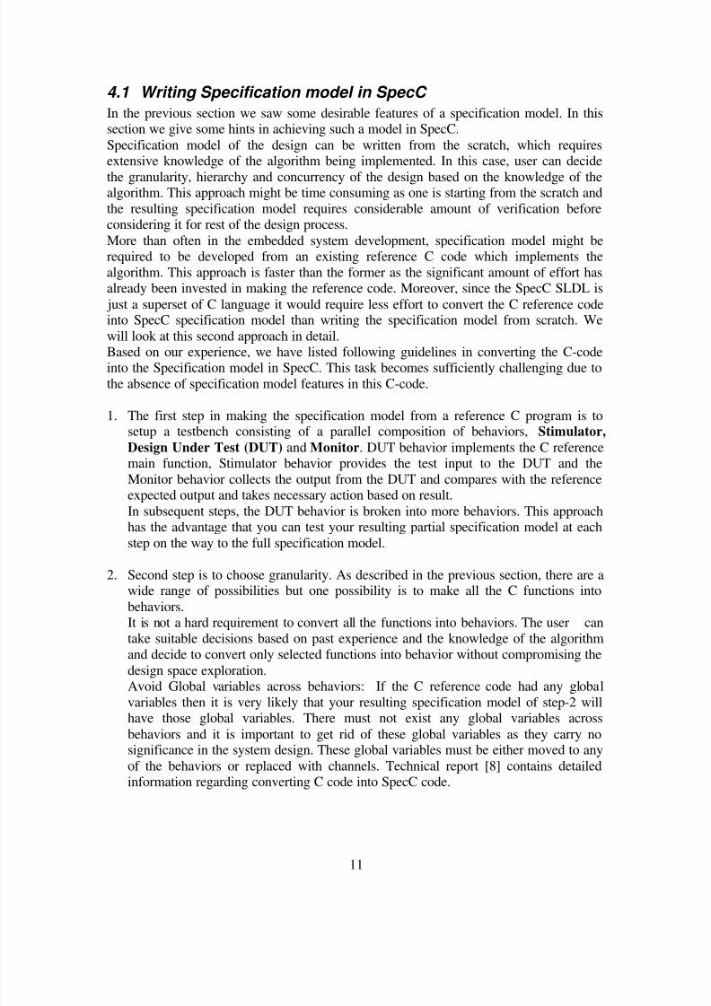
1. The first step in making the specification model from a reference C program is tosetup a testbench consisting of a parallel composition of behaviors, Stimulator,
Design Under Test (DUT) and Monitor. DUT behavior implements the C referencemain function, Stimulator behavior provides the test input to the DUT and the
Monitor behavior collects the output from the DUT and compares with the referenceexpected output and takes necessary action based on result.
In subsequent steps, the DUT behavior is broken into more behaviors. This approach
has the advantage that you can test your resulting partial specification model at eachstep on the way to the full specification model.
2. Second step is to choose granularity. As described in the previous section, there are awide range of possibilities but one possibility is to make all the C functions into
behaviors.It is not a hard requirement to convert all the functions into behaviors. The user can
take suitable decisions based on past experience and the knowledge of the algorithmand decide to convert only selected functions into behavior without compromising the
design space exploration.Avoid Global variables across behaviors: If the C reference code had any global
variables then it is very likely that your resulting specification model of step-2 willhave those global variables. There must not exist any global variables across
behaviors and it is important to get rid of these global variables as they carry nosignificance in the system design. These global variables must be either moved to any
of the behaviors or replaced with channels. Technical report [8] contains detailedinformation regarding converting C code into SpecC code.
8/3/2019 Case Study on Mp3 Format
http://slidepdf.com/reader/full/case-study-on-mp3-format 14/26
12
3. Introducing concurrency into your specification model: The various behaviors can becomposed as sequential, concurrent, pipelined or FSMD modules. After step-3 your
module will be just sequential. Look for any apparent concurrency in the algorithmand compose those behaviors as concurrent modules. Many a times, these algorithms
might not have any inherent concurrent modules, in that case concurrency can be
achieved by means of pipelining.Technical report [8] contains detailed information regarding converting C code intoSpecC code
4. Separation of Computation from Communication: This will be naturally taken care of
after the above steps are completed.
4.2 Case Study: MP3 Decoder
In this project we were required to write the specification model of the MPEG-1 Audio
Layer 3 (popularly known as MP3) decoder and produce an implementation model bytaking the specification model through a sequence of system level design steps. In this
section we will describe the steps we performed to arrive at the specification model.
We started with a reference C code for MP3 decoder [4] and applied the general
methodology described in the previous sections to this specific case to arrive at the finalspecification model. These steps are described in detail below:
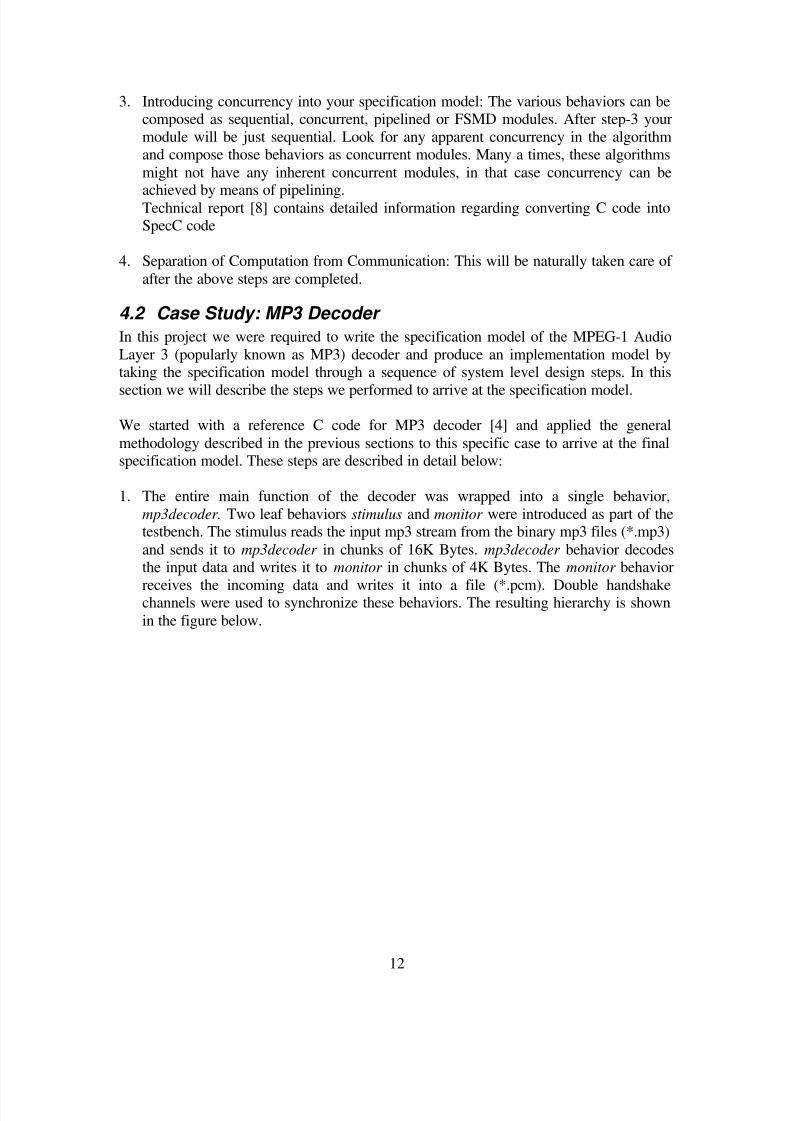
1. The entire main function of the decoder was wrapped into a single behavior,
mp3decoder. Two leaf behaviors stimulus and monitor were introduced as part of thetestbench. The stimulus reads the input mp3 stream from the binary mp3 files (*.mp3)
and sends it to mp3decoder in chunks of 16K Bytes. mp3decoder behavior decodesthe input data and writes it to monitor in chunks of 4K Bytes. The monitor behavior
receives the incoming data and writes it into a file (*.pcm). Double handshakechannels were used to synchronize these behaviors. The resulting hierarchy is shown
in the figure below.

8/3/2019 Case Study on Mp3 Format
http://slidepdf.com/reader/full/case-study-on-mp3-format 15/26
13
Figure 6 Testbench Design
2. The second step was to introduce granularity into our DUT mp3decoder. It would
have been ideal to convert each of the C functions in the decoder into behaviors. Butconsidering the time available to complete the project the idea was not feasible.
Alternatively, we decided to convert only critical functions in the decoder intobehaviors. To get information on the critical functions, we ran the GNU profiler,
gprof and obtained the relative execution time of each of the functions. From theprofiler result we identified following critical functions.
Function Percentage execution time
Synthesis filter 73%
Stereo Processing 6%
Hybrid Processing 6.9%
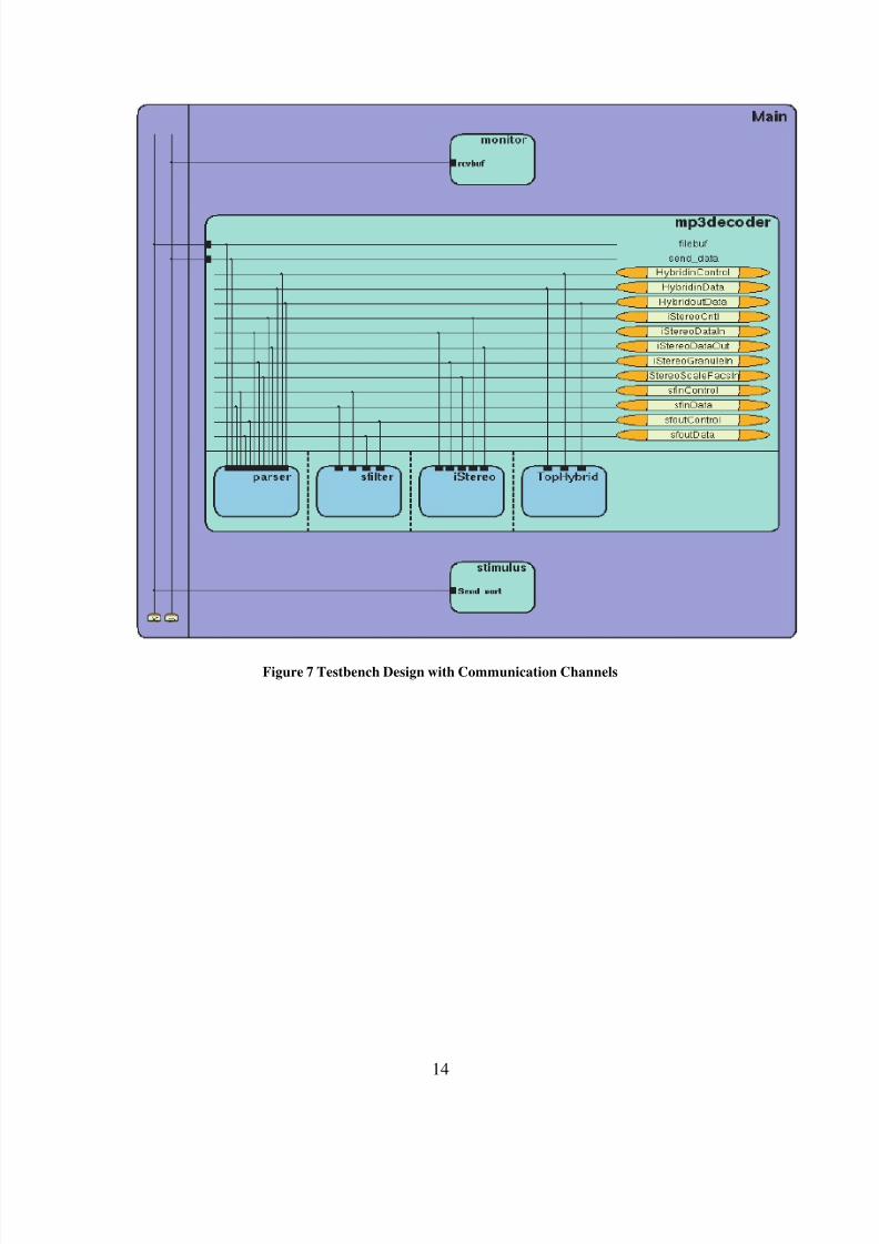
Based on this, we decided to convert just these functions into behaviors. The resultinghierarchy and connectivity is shown in Figure 7. The hybrid processing was further
decomposed to contain DCT36 and DCT12 behaviors. The resulting final hierarchy
of the decoder is shown in Figure 8.
8/3/2019 Case Study on Mp3 Format
http://slidepdf.com/reader/full/case-study-on-mp3-format 16/26
14
Figure 7 Testbench Design with Communication Channels
8/3/2019 Case Study on Mp3 Format
http://slidepdf.com/reader/full/case-study-on-mp3-format 17/26
15
Figure 8 Testbench Design Detailed Representation
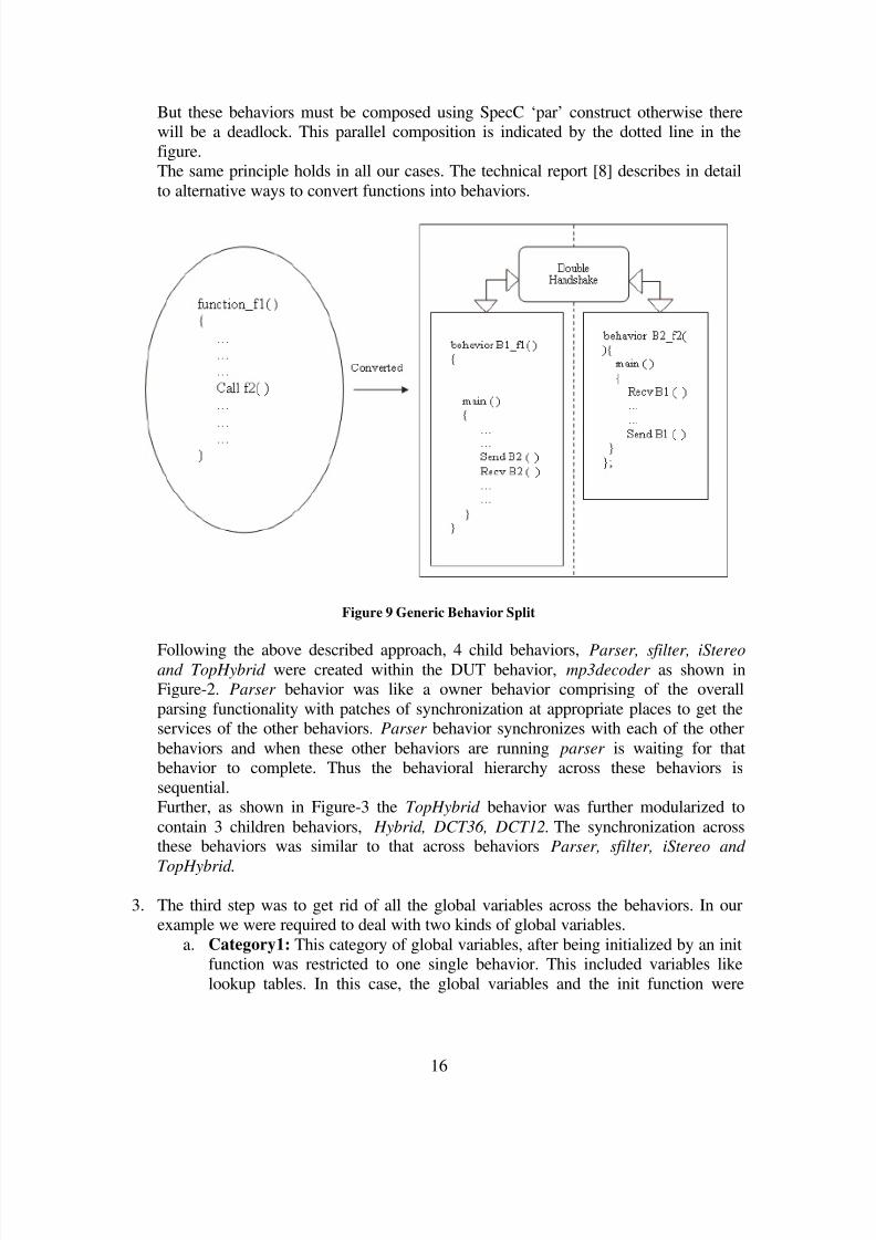
Now we will describe in detail how we converted the functions into behaviors. Wewould like to illustrate this with a simple example shown in Figure 9. In this example,
there is a C function f1 ( ) calling another function f2 ( ). This is shown on the lefthand side of the figure encapsulated in oval. We decide to convert f1 and f2 into
separate behaviors. The result is depicted on the right hand side of the figure. Thebehavior B1_f1 and B2_f2 are the behaviors corresponding to the functionality of the
f1 ( ) and f2 ( ) respectively. The call to the function f2 ( ) from f1 ( ) is replaced withthe send and receive calls of the double handshake channel. A double handshake
channel is used to communicate the function parameters of f2( ). There will be asmany channels as the number of parameters.
Now, how are these behaviors composed? If you notice the synchronization between
the two behaviors, first B1_f1 runs till the synchronization point is reached and aftersending the data it blocks on receive( ) function until the B2_f2 sends the result back
at the end of its execution. Thus the two behaviors are executed sequentially. This issimilar to a Remote Procedure Call (RPC).
8/3/2019 Case Study on Mp3 Format
http://slidepdf.com/reader/full/case-study-on-mp3-format 18/26
16
But these behaviors must be composed using SpecC ‘par’ construct otherwise therewill be a deadlock. This parallel composition is indicated by the dotted line in the
figure.The same principle holds in all our cases. The technical report [8] describes in detail
to alternative ways to convert functions into behaviors.
Figure 9 Generic Behavior Split
Following the above described approach, 4 child behaviors, Parser, sfilter, iStereoand TopHybrid were created within the DUT behavior, mp3decoder as shown inFigure-2. Parser behavior was like a owner behavior comprising of the overall
parsing functionality with patches of synchronization at appropriate places to get theservices of the other behaviors. Parser behavior synchronizes with each of the other
behaviors and when these other behaviors are running parser is waiting for thatbehavior to complete. Thus the behavioral hierarchy across these behaviors is
sequential.Further, as shown in Figure-3 the TopHybrid behavior was further modularized to
contain 3 children behaviors, Hybrid, DCT36, DCT12. The synchronization acrossthese behaviors was similar to that across behaviors Parser, sfilter, iStereo and
TopHybrid.
3. The third step was to get rid of all the global variables across the behaviors. In ourexample we were required to deal with two kinds of global variables.
a. Category1: This category of global variables, after being initialized by an initfunction was restricted to one single behavior. This included variables like
lookup tables. In this case, the global variables and the init function were
8/3/2019 Case Study on Mp3 Format
http://slidepdf.com/reader/full/case-study-on-mp3-format 19/26
17
moved to the behavior requiring them thus restricting the access of thesevariables to just one behavior.
b. Category2: This category included global variables used for both read andwrite across the behaviors. In our case, since all the behaviors were essentially
sequential, we resolved this by moving those global variables into the
behavior (owner behavior) which corresponds to the start point of thesequential execution. The other behaviors requiring these variables will besent by owner behavior through channels and the updated values are received
through the channels from the other behaviors and the actual variable will beupdated by the owner behavior.
4. Concurrency: The behaviors were all composed in parallel as seen in Figure-3. But
the synchronization implemented between these channels made their executionsequential.
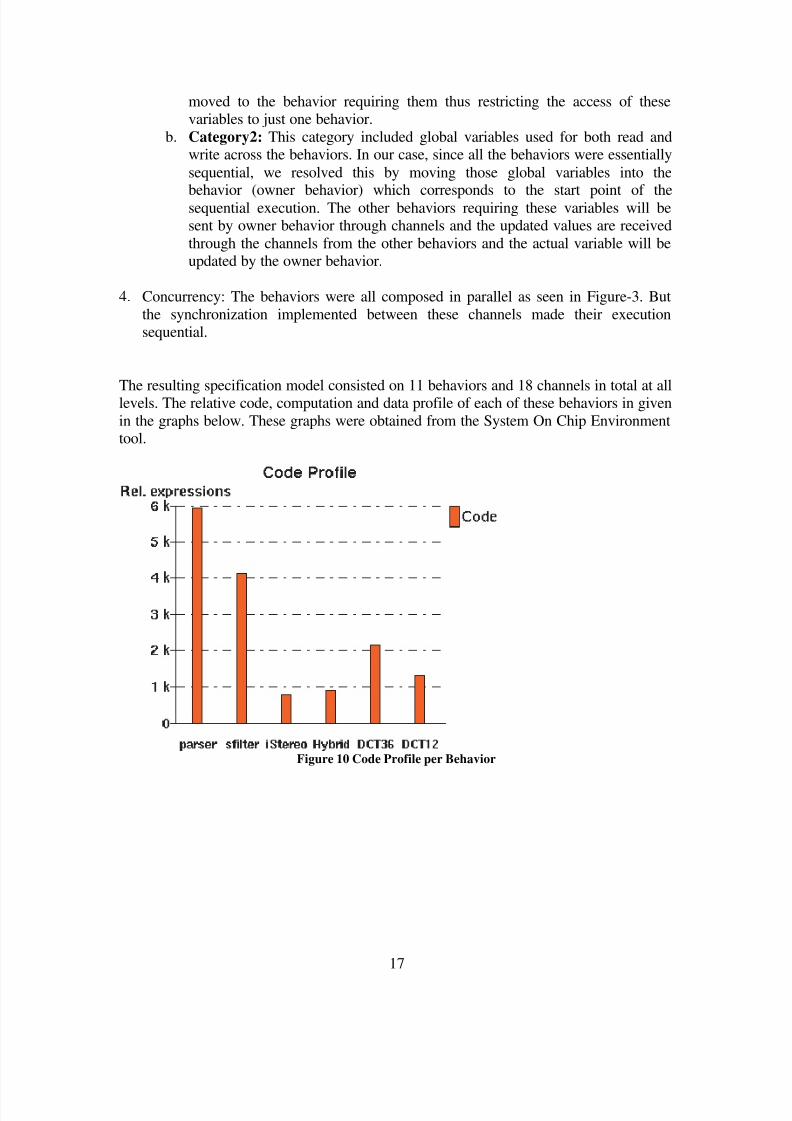
The resulting specification model consisted on 11 behaviors and 18 channels in total at alllevels. The relative code, computation and data profile of each of these behaviors in given
in the graphs below. These graphs were obtained from the System On Chip Environmenttool.
Figure 10 Code Profile per Behavior

8/3/2019 Case Study on Mp3 Format
http://slidepdf.com/reader/full/case-study-on-mp3-format 20/26
18
Figure 11 Distribution of Computation among Behaviors
Figure 12 Total Size of Variables per Behavior
8/3/2019 Case Study on Mp3 Format
http://slidepdf.com/reader/full/case-study-on-mp3-format 21/26
19
5 Design Space Exploration
The next step in the system level design process is the Design Space Exploration. In thisstep we will use the specification model of the MP3 decoder and carry out the following
exploration and synthesis process:• Architectural Exploration and Refinement: In this step, the behaviors of the
specification model are mapped to the components of the system architecture.
This step can be further divided into:a. Allocation of the set of Processing Elements (PE) from the IP library.
b. Partitioning of the behaviors onto the PEs.c. Mapping of the variables into the memory.
d. Scheduling of the behaviors on the sequential PEs.
• Communication Exploration and Synthesis: In this step, abstractcommunication between components is refined into an actual implementation
over wires and protocols of system busses. This step can be further divided into:a. Allocation of system bussesb. Partitioning of channels onto busses
c. Protocol and transducer insertion.d. Inlining of communication on components
e. Communication synthesis.
For detailed description of each of these steps, please refer to [2].To carry out each of these steps we used System On Chip Environment (SCE) tool [6].
Most of the above listed steps are automated in the tool and the user is just required toallocate components, map them to the PE and choose appropriate command to arrive at
the refined model.In the subsequent sections we will describe the various design explorations we performed
and how we arrived at the final architecture and communication decisions.
5.1 IP Library:
The PE library of the SCE tool available for this experiment consists of a couple of
general purpose processors, DSPs and a custom hardware. The general purposeprocessors included Motorola Coldfire r and Toshiba TX49H2. DSPs include Motorola
56600. Since our algorithm is implemented using floating point arithmetic, MotorolaDSP which does not support floating point unit was not useful. So we restricted our
exploration to general purpose processors, Motorola Coldfire and Toshiba TX49H2 andthe custom hardware unit.
Among the buses, there were 4 busses available: Motorola Coldfire M bus, Toshiba Gbus, Motorola DSP56600 and Samsung KM 684002A buses. Based on our PE selection
we restricted to Motorola Cold fire bus and Toshiba G bus.Similarly, for memory modules, we will restrict our exploration to Motorola Coldfire
SRAM and Samsung KM684002A.
8/3/2019 Case Study on Mp3 Format
http://slidepdf.com/reader/full/case-study-on-mp3-format 22/26
20
5.2 Exploration 1:
PE: Toshiba TX49H2
Memory: Samsung KM684002A memory.
Bus: Single PE, Processor native bus.
The procedure for detailed architectural exploration is given the SCE tutorial document
[6].Toshiba TX49H2 is a 64 bit 200 MHz RISC processor. With this configuration, for mp3
stream funky.mp3 with a real time length of 1:02 minutes, we got an estimated run timeof 5 Secs. Though the resulting architectural model simulated to produce bit accurate
output, due to the limitation in the tool we could not verify the estimated run time of 5Secs.
We proceeded with the next step of scheduling of behaviors onto this PE. We chose to do
Round-Robin scheduling for all the behaviors. We could not explore the other possibilityof serializing the behaviors and static scheduling due to the synchronization that existedbetween behaviors in our specification model. The tight coupling between the behaviors
required that every behavior should be dynamically scheduled using either round-robin orpriority based scheduling.
The resulting model of scheduling refinement compiled and simulated but still due to thelimitation of the tool, timing detail was missing.
Since there was only one PE, it was not required to allocate any busses and we carried out
the network refinement and the communication refinement. The resulting modelcompiled, simulated and verified to produce bit accurate output.
Since we did not have any custom hardware elements in this exploration we skipped the
RTL refinement and proceeded to C code generation. Due to the limitation in the tool wecould not carry out the C code generation.
Since the estimated runtime looked too optimistic, we verified the parameter table
containing “cycles per operation” of the processor. The MP3 decoder implementation isheavily based on floating point operations. Exactly those operations are wrongly captured
in that table to take only a single cycle. Checking with the processors specification [7] wefound, that an integer division already takes 36 cycles. Due to this discrepancy we did not
further explore the due based on the Toshiba TX49H2.
8/3/2019 Case Study on Mp3 Format
http://slidepdf.com/reader/full/case-study-on-mp3-format 23/26
21
5.3 Exploration 2:
PE: Motorola ColdfireMemory: Samsung Motorola Coldfire SRAM.
Bus: Single PE, Processor native bus.
A second set of exploration was performed using a single CPU a Motorola ColdFire with120MHz. All behaviors were allocated to this processing unit. Executing the decoding of
the test stream funky.mp3 with a real time length of 1:02 minutes, took an estimated 27.8seconds. Without further verification we assume that this result seems reasonable and
continued working with this solution.The timing figures before indicate that there is a significant safety margin in computing
power, the test stream was decoded in half its real time playing time. To reduce the powerrequirements, the clock frequency was reduced to 60MHz. Using this lower clock speed
the same test stream still decodes within 55.5 seconds. In order to verify if the timingconstrains are met in all cases and not in average only, we would need to refer to
simulation timing. However this could not be done. Although our design contains thetiming restriction, the architecture refinement tool does only insert timing informationbased on the behavior level. Since our behaviors are complex and perform the work
within a while loop, simulation timing information was not available.As in the previous exploration we did chose a dynamic scheduling algorithm. Again
dynamic scheduling is required, since we have parallel behaviors, which communicatewithin their execution via channels. Therefore it is not possible to use static scheduling.
The communication and network refinement is trivial for this exploration since all code isexecuted on the ColdFire. In order to satisfy the tool set constrains, we have allocated the
ColdFire native bus and communication protocol. The ColdFire itself is master and slaveon that bus. To emphasize again, no real communication is performed on the physical bus.
The presented solution is a pure software solution; therefore in the ImplementationRefinement no RTL code generation was performed. This refinement was performed for
the SW and C code was generated for the ColdFire target. However, a limitation in the Ccode generator did not allow us to proceed to the final executable. Therefore we could not
verify that the timing restrictions are met with the cycle accurate model.
8/3/2019 Case Study on Mp3 Format
http://slidepdf.com/reader/full/case-study-on-mp3-format 24/26
22
5.4 Exploration 3:
PE: Motorola Coldfire, Custom HardwareMemory: Samsung Motorola Coldfire SRAM.
Bus: Motorola Coldfire M bus.
The goal of this exploration was to take the results of the previous exploration with asingle ColdFire processor and attempt to reduce the clock frequency further for power
saving reasons. In order to still meet the timing requirements, a custom hardware block with a 100MHz clock frequency is allocated. The computationally most intensive part,
the Synthesis Filter was allocated to this block. All other behaviors are executed on theColdFire (with up to now 60MHz). Unexpectedly using additional hardware did not
speed up the execution. Instead of an execution time of 55.5 seconds for the pureColdFire implementation, the execution now takes 62.1 seconds on the CPU and 13.4
seconds on the custom hardware. We assume that this result is due to the nature of ourspecification, which does not yet explore parallelism. As described before the behaviors
are introduced as blocking calls on a dual handshake channel. Therefore they have thetiming semantic of blocking PRC call and do not allow parallelism. The CPU is idlewhile the hardware unit performs the computation.
Due this restriction we did not follow further exploration with a split hardware/softwareimplementation.
6 ImplementationAs the previous chapter explains the architecture with a single ColdFire processor waschosen for the implementation. The previous chapter did also describe the further
refinement activities on that design. These refinements resulted in the implementation
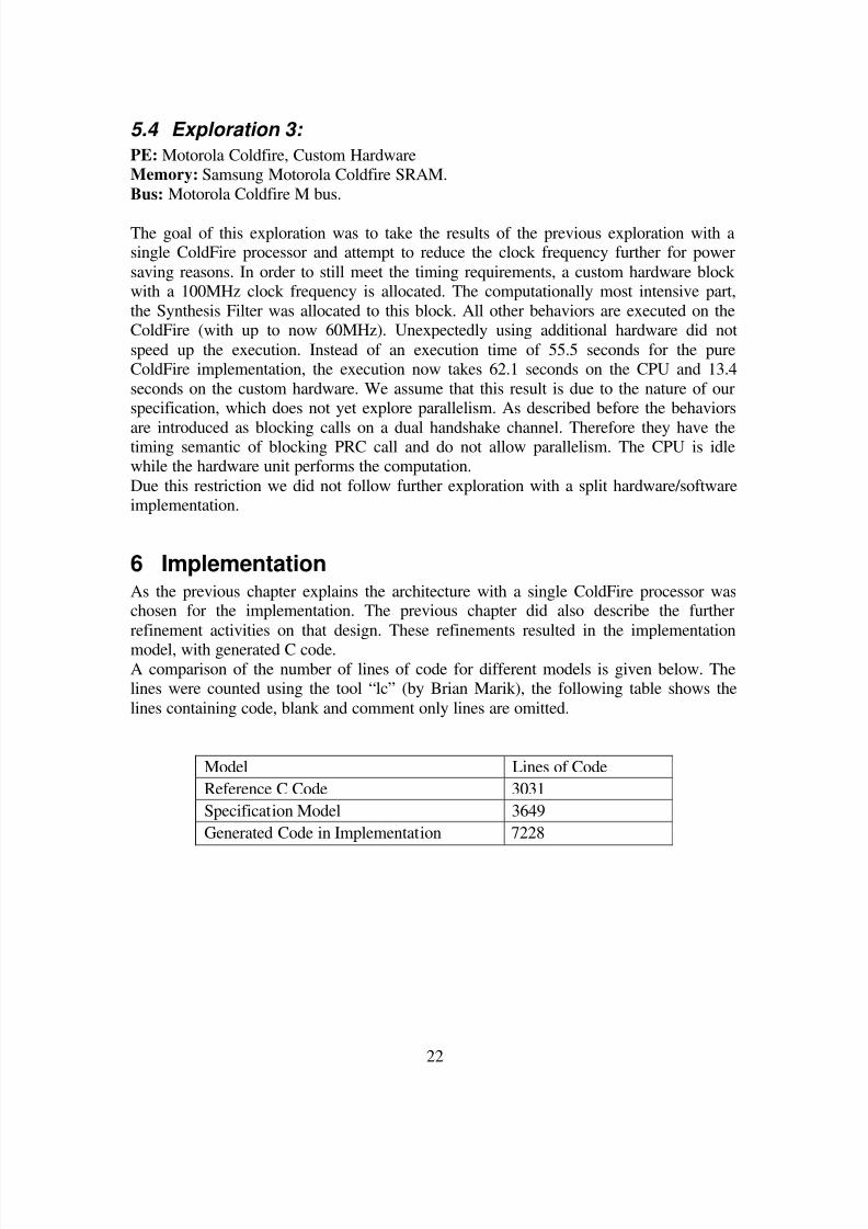
model, with generated C code.A comparison of the number of lines of code for different models is given below. Thelines were counted using the tool “lc” (by Brian Marik), the following table shows the
lines containing code, blank and comment only lines are omitted.
Model Lines of Code
Reference C Code 3031
Specification Model 3649
Generated Code in Implementation 7228
8/3/2019 Case Study on Mp3 Format
http://slidepdf.com/reader/full/case-study-on-mp3-format 25/26
23
7 ConclusionIn this project we implemented the specification model of an MP3 decoder in SpecC
SLDL and followed the system level design procedure using System-On-Chipenvironment to arrive at the final implementation model of the decoder.
We chose SpecC as a language to implement the specification model as it best suits fordescribing systems involving both hardware and software components. Being a true
superset of ANSI-C it has a natural suitability to describe software components. It hasadded features like signals, wait, notify etc. to support hardware description. It also
includes constructs to support hierarchical description of system components. With allthese features, the designer has flexibility to choose and describe the system under design
at any desired level of abstraction. SpecC is easy to learn and a clean language. Anyonewith background knowledge of C can learn SpecC.
Besides the SpecC language the System-on-Chip environment presented a major supportfor completing the project. Although, it is in its early development stage, it allows an easy
design space exploration. It enables the designer to estimate performance during the early
stages of the design and additionally allows the early pruning of the design space.We spent most of our time in converting an existing C code into the Specification model.Unfortunately a noticeable effort had to be spent since the originating code was not
ANSI-C compliant and frequently used a small feature of variable initialization notavailable in SpecC. The most challenging part was the conversion from the strictly
sequential C code, which heavily relied on global variables. In order to break up the codeinto behaviors, these global variables have to be attached to behaviors and the
communication has to be mapped to channels. Clearly the originating C code did notfollow the separation of computation and communication. Unfortunately due to time
restrictions we only completed the first set of behaviors. With the limited amountbehaviors we could not fully explore the possibilities in concurrency, which also limited
us in the design exploration.Future work on this topic could start with our Specification Model and create more
behaviors. With sufficiently breaking up the code into behaviors a clean design can beachieved which will consist of concurrent modules of the code. This will enable efficient
mapping of behaviors to concurrent processing elements and exploitation of parallelism.

8/3/2019 Case Study on Mp3 Format
http://slidepdf.com/reader/full/case-study-on-mp3-format 26/26
8 References
1. Rainer Doemer, ECE 298: System-on-Chip Description and Modeling, Lecture
Notes, 20042. A. Gerstlauer, R. Doemer, J. Peng, D. Gajski: "System Design: A Practical Guide
with SpecC",Kluwer Academic Publishers, Boston, June 2001. ISBN 0-7923-
7387-1
3. MP3 Decoder Master's Thesis: http://www.kmlager.com/thesis.php
4. MP123 Decoder, http://www.mpg123.de/mpg123/mpg123-0.59r.tar.gz
5. Th. Groetker, St. Liao, G. Martin, St. Swan, "System Design with SystemC",
Kluwer Academic Publishers, Boston, May 2002. ISBN 1-4020-7072-1
6. Samar Abdi, Junyu Peng, Haobo Yu, Dongwan Shin, Andreas Gerstlauer, Rainer
Doemer,Daniel Gajski, System-on-Chip Environment, SCE Version 2.2.0 Beta,
Tutorial
7. Toshiba, 64-Bit TX System RISC TX49/H2 Core Architecture, JAN. 2002,
8. Gerstlauer, K. Ramineni, R. Doemer, D. Gajski, System-on-Chip Specification
Style Guide, http://www.ics.uci.edu/~doemer/publications/CECS_TR_03_21.pdf