case study capping semi-liquids -...
TRANSCRIPT
CASE STUDY By Dave Anderson
Capping Semi-Liquids with Geosynthetic Layers Problem: A U.S.-based polyethylene and polyester resin/polymer producer recently closed a manufacturing facility in Wilmington, N.C. . The company hired an engineering firm to manage the demolition and removal of the expansive structures and infrastructure. Part of the environmental responsibilities was to also find a viable solution for closing a 12-acre sludge basin. But first, the engineers needed to determine sludge volume and understand which dewatering methods would be the most effective.
Solution: The engineering firm determined the best approach was to cap the solids in place. The depth of the sludge ranged from 7ft to 9ft across the basin, so developing a safe, effective, and economical solution was a priority. A plan was needed to enable a crew
Result: Closing the basin full of solids proved to be successful and cost-effective. Costs normally associated with dewatering and hauling solids were avoided by using the layered grid and membrane methods. The project stayed within budget and was completed on time without any safety violations. This new method to capping solids could possibly be utilized for other industrial closures such as coal ash, mining operations, or any site that contains a non-solidified sludge.
40 Geosynthetics | October November 2016 www.GeosyntheticsMagazine.com 41
Introduction
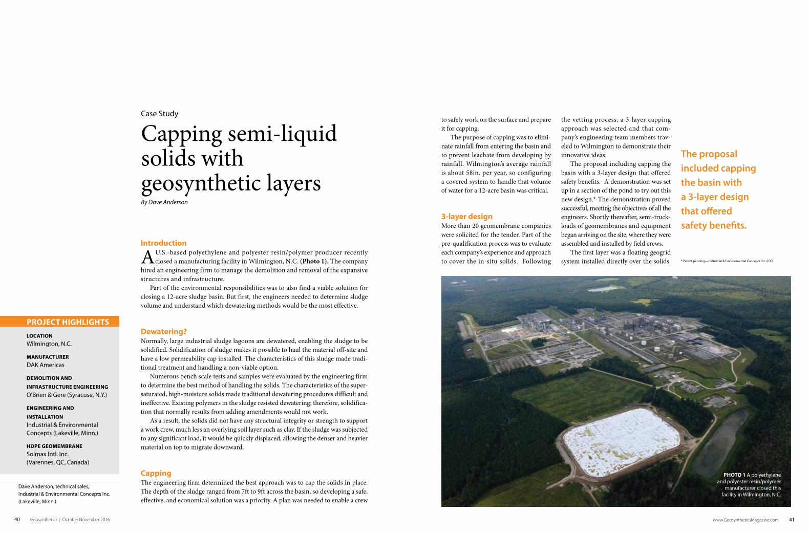
A U.S.-based polyethylene and polyester resin/polymer producer recently closed a manufacturing facility in Wilmington, N.C. (Photo 1). The company
hired an engineering firm to manage the demolition and removal of the expansive structures and infrastructure.
Part of the environmental responsibilities was to also find a viable solution for closing a 12-acre sludge basin. But first, the engineers needed to determine sludge volume and understand which dewatering methods would be the most effective.
Dewatering?Normally, large industrial sludge lagoons are dewatered, enabling the sludge to be solidified. Solidification of sludge makes it possible to haul the material off-site and have a low permeability cap installed. The characteristics of this sludge made tradi-tional treatment and handling a non-viable option.
Numerous bench scale tests and samples were evaluated by the engineering firm to determine the best method of handling the solids. The characteristics of the super-saturated, high-moisture solids made traditional dewatering procedures difficult and ineffective. Existing polymers in the sludge resisted dewatering; therefore, solidifica-tion that normally results from adding amendments would not work.
As a result, the solids did not have any structural integrity or strength to support a work crew, much less an overlying soil layer such as clay. If the sludge was subjected to any significant load, it would be quickly displaced, allowing the denser and heavier material on top to migrate downward.
CappingThe engineering firm determined the best approach was to cap the solids in place. The depth of the sludge ranged from 7ft to 9ft across the basin, so developing a safe, effective, and economical solution was a priority. A plan was needed to enable a crew
Case Study
Capping semi-liquid solids with geosynthetic layersBy Dave Anderson
PROJECT HIGHLIGHTS
LOCATION
Wilmington, N.C.
MANUFACTURER
DAK Americas
DEMOLITION AND
INFRASTRUCTURE ENGINEERING
O’Brien & Gere (Syracuse, N.Y.)
ENGINEERING AND
INSTALLATION
Industrial & Environmental Concepts (Lakeville, Minn.)
HDPE GEOMEMBRANE
Solmax Intl. Inc. (Varennes, QC, Canada)
Dave Anderson, technical sales, Industrial & Environmental Concepts Inc. (Lakeville, Minn.)
PHOTO 1 A polyethylene and polyester resin/polymer
manufacturer closed this facility in Wilmington, N.C.
to safely work on the surface and prepare it for capping.
The purpose of capping was to elimi-nate rainfall from entering the basin and to prevent leachate from developing by rainfall. Wilmington’s average rainfall is about 58in. per year, so configuring a covered system to handle that volume of water for a 12-acre basin was critical.
3-layer designMore than 20 geomembrane companies were solicited for the tender. Part of the pre-qualification process was to evaluate each company’s experience and approach to cover the in-situ solids. Following
The proposal included capping the basin with a 3-layer design that offered safety benefits.
the vetting process, a 3-layer capping approach was selected and that com-pany’s engineering team members trav-eled to Wilmington to demonstrate their innovative ideas.
The proposal including capping the basin with a 3-layer design that offered safety benefits. A demonstration was set up in a section of the pond to try out this new design.* The demonstration proved successful, meeting the objectives of all the engineers. Shortly thereafter, semi-truck-loads of geomembranes and equipment began arriving on the site, where they were assembled and installed by field crews.
The first layer was a floating geogrid system installed directly over the solids. * Patent pending—Industrial & Environmental Concepts Inc. (IEC)

42 Geosynthetics | October November 2016 www.GeosyntheticsMagazine.com 43
Capping semi-liquid solids
casings were fastened to adjacent cover sections to create a semi-monolithic cover to support the workers and the top layer.
Due to the ultraviolet rays and high summer temperatures of North Caro-lina, a white 80-mil HDPE geomembrane was installed, stretching across the entire 12-acre basin (Photo 3). The material was double-fusion welded to create a monolithic flexible cover that protected the solids underneath from rainwater.
The cover was designed to stay afloat, keeping the upper surface above the solids, enabling rainwater to be collected and diverted off the cover. A series of strategically placed ballast weights were installed across the cover
The grid was installed to distribute surface loads across a wider area, which reduced the displacement of solids (Photo 2).
The secondary layer was installed directly over the geogrid. A patented floating modular cover system provided the needed structure to further distribute weight across a large area of the solids. The buoyancy of the modular cover pro-vided a working platform to support the working crew and its equipment.
GeomembraneThe modular cover was constructed of high-density polyethylene (HDPE) that encapsulated a proprietary foam in an airtight module. The individual modular PHOTO 2 The geogrid was installed to distribute surface loads across a wider area. PHOTO 3 A white 80-mil HDPE geomembrane was installed, stretching across the entire 12-acre basin.
www.plastikakritis.com | www.seven-layer.com/en
A brand of

44 Geosynthetics | October November 2016 www.GeosyntheticsMagazine.com 45
>> For more, search waste capping at www.GeosyntheticsMagazine.com
ConclusionClosing the basin full of solids proved to be successful and cost-effective. Costs normally associated with dewatering and hauling solids were avoided by using the layered grid and membrane methods.
The project stayed within budget and was completed on time without any safety violations. This new method to capping solids could possibly be utilized for other industrial closures such as coal ash, min-ing operations, or any site that contains a non-solidified sludge. G
PHOTO 4 The geomembrane was buried in a perimeter anchor trench and backfilled.
to facilitate the draining of rainwater to collection points.
The geomembrane was buried in a perimeter anchor trench and backfilled (Photo 4). The anchor trench design not only prevents rainwater from entering the basin, but keeps wind from getting under the cover, important in this area due to the frequency of hurricane winds and heavy rainfall.
BiogasThe solids in the basin were relatively inert, producing minimal biogas. How-ever, as a precaution for the potential need to collect biogas, prefabricated gas laterals were installed.
The field crew welded the floats to the underside of the top layer to enable gas to migrate above the solids where they could be expelled through a series of valves. The valves can be opened by operators if the need develops in the future.
Capping semi-liquid solids