case study: 16 mw combined cycle cogeneration plant for a
TRANSCRIPT

Case Study: 16 MW Combined Cycle Cogeneration Plant for a
University Campus

Campus Facts and Figures
Established 1863 First central heating plant 1910 First cogeneration 1943 coal fired Extensive low pressure steam distribution
system now serving 11 million SF building area Medium pressure steam distribution for
specialized uses and reinforcement of LP system Electrical utility service at 13.8 kV shared
between East and West sides. 25 MW peak electric, 290,000 lb./hr. peak steam

Steam distribution system – all 13 miles

Back in 1910 – First steam plant on edge of campus

1943 Turbine Hall

Previous plant configuration - 2008
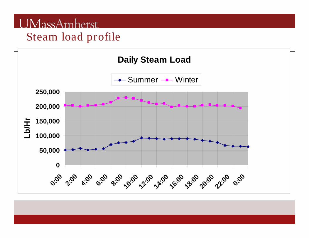
Steam load profile
Daily Steam Load
0
50,000
100,000
150,000
200,000
250,000
0:00
2:00
4:00
6:00
8:00
10:00
12:00
14:00
16:00
18:00
20:00
22:00 0:0
0
Lb/H
r
Summer Winter

Electrical load profileDaily Electrical Profiles
0
5,000
10,000
15,000
20,000
25,000
0:00
2:00
4:00
6:00
8:00
10:00
12:00
14:00
16:00
18:00
20:00
22:00 0:0
0
kW
Summer Fall Winter Break

Design options for electrical/thermal load matching Ratio of electrical power to thermal
input depends on plant type. • Existing backpressure steam turbine – 10%• Higher pressure bpst – 18%• Gas turbine simple cycle – 27%• Reciprocating diesel – 35%• Gas turbine/steam turbine combined cycle
with variable duct firing – 32-50% Our load profiles allowed us to take
advantage of the gas turbine/combined cycle option.

New Plant Design
Solar Mars 10 mw combustion turbine Rentech Heat Recovery Steam Generator,
120,000 #/hr. @ 600 psig. 3-125,000 #/hr Boilers, 1@ 600psig, 2@ 200
psig (to meet winter heating load with backup) 3.5 MW Backpressure Steam Turbine 200/15
psig, (from existing plant) 2.0 MW Backpressure Steam Turbine 600/200
psig. Future Boiler, size & fuel TBD.

New Plant Configuration
Kitchen Equipment
Lab Sterilizers
High to Low ReinforcementWinter Use Space Heating
10-220 kLb/hr.Domestic Water Heating
0-50 kLb./hr. Steam Chillers
0-40,000 #/hr SummerStandby and Line Losses
30,000 #/hr
Low Pressure (15psig)30,000-180,000 #/hr
Medium Pressure (100psig) 10,000-120,000 #/hr
4 MW Steam Turbine
PRV’s
5-10 MW Gas Turbine
HRSG
600 psig Boiler
Future Boiler
200 psig Boiler
200 psig Boiler
2 MW Future Steam Turbine
PRV’s
PRV’s
200 psig Header
600 psig Header
Exhaust to Controls
Fuels:Oil, Gas
Gas Oil, Gas ??? Oil,
GasOil, Gas

Typical Gas Turbine/HRSG performance

New Plant Design Features
Latest pollution control technologies including advanced Solar Mars 10 mw combustion turbine, emissions guaranteed through 50-100% load range.
Selective Catalytic Reduction and Oxidation Catalyst technologies significantly reduce the emissions of NOx and CO. As applied to gas turbine, requires exhaust flow through HRSG with corresponding steam generation.
Fuel supply primarily natural gas, interruptible, with ultra low sulfur #2 oil backup. Oil tank size constrained by architectural roof.

Plant Performance
The 16 MW plant peak performance requires 120,000 lb/hr. steam load, so occurs only in winter, and does not meet the 25 MW peaks which occur during the school year in May and September.
Steam absorption chilling does provide summer steam loads in excess of 100,000 lb/hr., albeit typically at increased operating cost.
The plant meets all night and weekend loads during the non cooling season however, and generates in excess of 75% of annual campus electrical use.

Demand vs. Generation May 2013

Demand vs. Generation February 2013
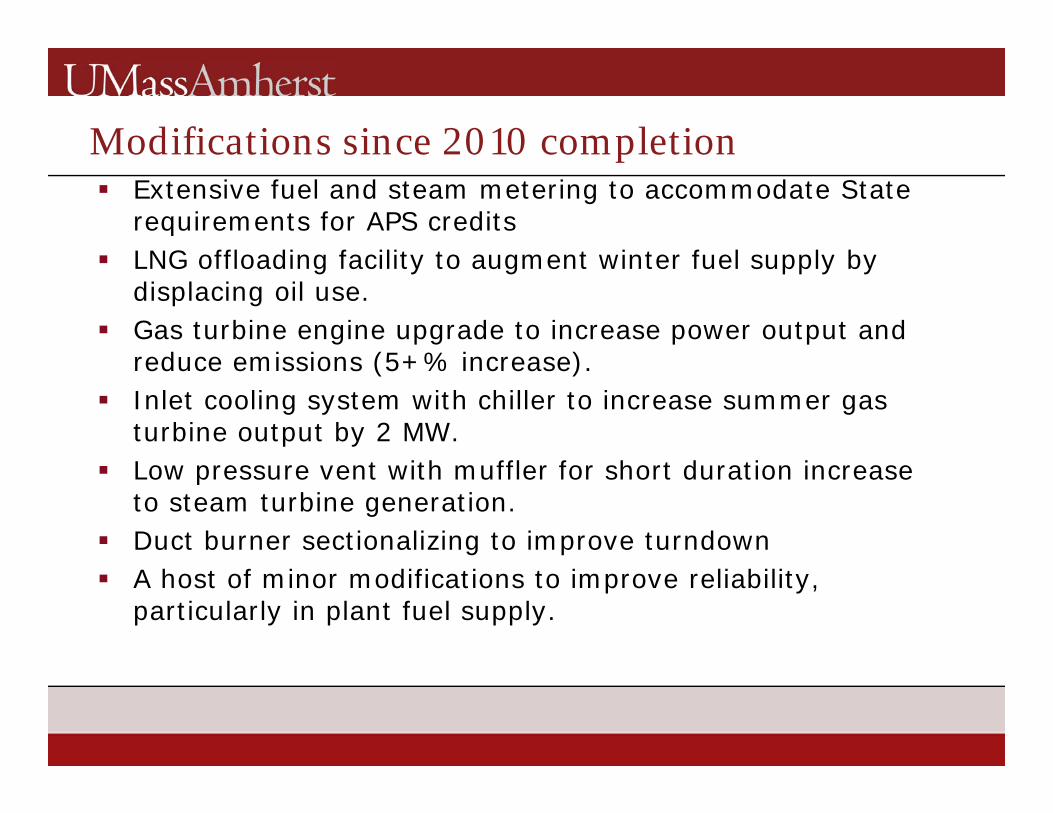
Modifications since 2010 completion Extensive fuel and steam metering to accommodate State
requirements for APS credits LNG offloading facility to augment winter fuel supply by
displacing oil use. Gas turbine engine upgrade to increase power output and
reduce emissions (5+% increase). Inlet cooling system with chiller to increase summer gas
turbine output by 2 MW. Low pressure vent with muffler for short duration increase
to steam turbine generation. Duct burner sectionalizing to improve turndown A host of minor modifications to improve reliability,
particularly in plant fuel supply.

Future Options
Biomass boiler. Unoccupied boiler position limited in size. Could require land taking of adjacent athletic field for boiler or fuel storage.
Alternate gas/liquid fuels, bio-derived.Possibility of remote storage/gasification.
Steam driven chilling. Most efficient option, turbine drive, requires licensed operators.
Need for additional steam capacity and desirability of additional electric capacity is foreseen with rapid growth of science buildings

Challenges to effective operation Electrical load matching: With two utility feeds sharing
campus load, neither able to meet peaks and utility company not wanting direct connection, we are challenged to fully serve low demand periods and keep our generation serving at least part of campus during a utility outage at high demand periods.
Solution: We use manually switched cross ties between East and West utility feeds to serve entire campus with cogeneration at low demand, normally paralleling to West side only, and open these cross ties to split campus utility inputs when utility disruptions are feared or generation capacity is offline. Load shedding controls are in place to drop selected distribution feeders and maintain generation capacity to at least part of campus in a utility outage.
Challenges to effective operation
Steam load tracking: The plant was designed based on steam metered data from the old plant. This, as does our current metering, comes from steam generator meters, not output to campus. These meters in the old plant served significant parasitic loads, and so the minimum steam generator output in summer dropped lower than expected from previous records, (< 60,000 lb./hr). The optimal steam generator, the HRSG, could not turn down below 57,000 lb./hr. without loss of critical emission control.
Solution: Segregate the four bar duct burner array into two groups so that one could be fired at a time and maintain emissions control at lower outputs. HRSG output can then track actual campus loads without need to artificially create steam load with venting or less efficient steam chilling.

Challenges to effective operation Perhaps the significant cost of the plant, >
$150k, has raised expectations that it will help the campus withstand historically common utility electrical outages. The complex electrical switching and load shedding required has proven challenging to implement, and of course testing it without a utility outage is difficult. We have bought a large number of UPS units for the research community.
Solution: Improve relay coordinations, temper campus expectations, implement 115 kvtransmission level power procurement with a new dedicated campus electrical substation.

APS (Alternative Portfolio Standard) Credits
The Commonwealth of Massachusetts distributes incentives for efficient cogeneration with the use of natural gas.
Documenting this gas fired cogeneration in a multi-fuel plant to the satisfaction of State regulators has required extensive submetering of fuel and BTU flows and quarterly reporting along with annual calibration of those meters.
Revenues in the range of $300k/month have funded this metering and aforementioned plant efficiency improvements.

Questions?

Contacts
Jason Burbank, Campus Energy Engineer University of Massachusetts/Amherst Physical Plant Department [email protected]
