c/as2 acceptable solution for buildings other than risk
TRANSCRIPT

C/AS2
Acceptable Solution for Buildings other than Risk Group SH
For New Zealand Building Code Clauses C1-C6 Protection from Fire
BUILDING CODE
C

M I N I S T R Y O F B U S I N E S S , I N N O VAT I O N A N D E M P L O Y M E N T
PAGE 2 | 27 JUNE 2019 BUILDING CODE
CAcceptable Solution
DOCUMENT STATUS
Status of Verification Methods and Acceptable Solutions
Verification Methods and Acceptable Solutions are prepared by the Ministry of Business, Innovation and Employment in accordance with section 22 of the Building Act 2004. Verification Methods and Acceptable Solutions are for use in establishing compliance with the New Zealand Building Code.
A person who complies with a Verification Method or Acceptable Solution will be treated as having complied with the provisions of the Building Code to which the Verification Method or Acceptable Solution relates. However, using a Verification Method or Acceptable Solution is only one method of complying with the Building Code. There may be alternative ways to comply.
Defined words (italicised in the text) and classified uses are explained in Clauses A1 and A2 of the Building Code and in the Definitions at the start of this document.
Enquiries about the content of this document should be directed to:
Ministry of Business, Innovation and EmploymentPO Box 1473, Wellington.6140Telephone 0800 242 243Email: [email protected]
Verification Methods and Acceptable Solutions are available from www.building.govt.nz
ISBN (online) 978-1-98-857008-2
© Ministry of Business, Innovation and Employment 2020
This document is protected by Crown copyright, unless indicated otherwise. The Ministry of Business, Innovation and Employment administers the copyright in this document. You may use and reproduce this document for your personal use or for the purposes of your business provided you reproduce the document accurately and not in an inappropriate or misleading context. You may not distribute this document to others or reproduce it for sale or profit.
The Ministry of Business, Innovation and Employment owns or has licences to use all images and trademarks in this document. You must not use or reproduce images and trademarks featured in this document for any purpose (except as part of an accurate reproduction of this document) unless you first obtain the written permission of the Ministry of Business, Innovation and Employment.

M I N I S T R Y O F B U S I N E S S , I N N O VAT I O N A N D E M P L O Y M E N T
PAGE 3 | 5 NOVEMBER 2020BUILDING CODE
C Acceptable Solution
DOCUMENT STATUS
Document status
The most recent version of this document (Amendment 2), as detailed in the Document History, is approved by the Chief Executive of the Ministry of Business, Innovation and Employment. It is effective from 5 November 2020 and supersedes all previous versions.
The previous edition of this Acceptable Solution C/AS2, as amended, will cease to have effect on 3 November 2021.
People using this document should check for amendments on a regular basis. The Ministry of Business, Innovation and Employment may amend any part of any Acceptable Solution or Verification Method at any time. Up-to-date versions of Acceptable Solutions and Verification Methods are available from www.building.govt.nz
C: Document History
Date Alterations
First edition 27 June 2019
Amendment 1 (Errata 1)
Effective from 22 October 2019 until 3 November 2021
p. 34, Table 1.1 p. 43, Table 2.2b p. 44, Table 2.2c
Amendment 2 5 November 2020 p. 18 Contents pp. 19-21 References pp. 22–24, 26–27, 30–32 Definitions pp. 34, 36 Part 1 pp. 41, 48 Part 2
pp. 50, 57–58, 64–79, 82–87 Part 3 pp. 89–90, 95–100, 105, 108–118, Part 4 pp. 121–124, 128–136, 139–143 Part 5 pp 146–147 Part 7 pp. 155, 158 Appendix C

BUILDING CODE
CAcceptable Solution
CODE CL AUSES
Limit on application
C1—ObjeCtives Of Clauses C2 tO C6 (prOteCtiOn frOm fire)
Provisions
The objectives of clauses C2 to C6 are to:
(a) safeguard people from an unacceptable risk of injury or illness caused by fire,
(b) protect other property from damage caused by fire, and
(c) facilitatefirefightingandrescueoperations.
NEW ZEALAND BUILDING CODEClauses C1, C2, C3, C4, C5, C6
Department of BuilDing anD Housing – 10 april 2012 i 1
M I N I S T R Y O F B U S I N E S S , I N N O VAT I O N A N D E M P L O Y M E N T
PAGE 4 | 27 JUNE 2019 | NZBC C CLAUSES

BUILDING CODE
C Acceptable Solution
CODE CLAUSES
Limit on application
C2—preventiOn Of fire OCCurring
Provisions
FunctionaL requirement
c2.1 Fixed appliances using controlled combustionandotherfixedequipmentmust be designed, constructed, and installed in buildings in a way that reduces the likelihood of illness or injury due to fire occurring.
PerFormance
c2.2 The maximum surface temperature of combustible building materials close tofixedappliancesusingcontrolledcombustionandotherfixedequipmentwhen operating at their design level must not exceed 90°C.
c2.3 Fixed appliances using controlled combustionandotherfixedequipmentmust be designed, constructed and installed so that there is a low probability of explosive or hazardous conditions occurring within any spaces in or around the building that contains the appliances.
NEW ZEALAND BUILDING CODE Clauses C1, C2, C3, C4, C5, C6
2 i Department of BuilDing anD Housing – 10 april 2012
M I N I S T R Y O F B U S I N E S S , I N N O VAT I O N A N D E M P L O Y M E N T
PAGE 5 | 27 JUNE 2019 | NZBC C CLAUSES

BUILDING CODE
CAcceptable Solution
Limit on application
C3—fire affeCting areas beyOnd the fire sOurCe
Provisions
FunctionaL requirement
c3.1 Buildings must be designed and constructed so that there is a low probability of injury or illness to persons not in close proximity to a fire source.
c3.2 Buildings with a building height greaterthan10mwhereupperfloorscontain sleeping uses or other property must be designed and constructed so that there is a low probability of external vertical firespreadtoupperfloorsinthebuilding.
c3.3 Buildings must be designed and constructed so that there is a low probability of fire spread to other property vertically or horizontally across a relevant boundary.
Clause C3.2 does not apply to importance level 1 buildings.
NEW ZEALAND BUILDING CODEClauses C1, C2, C3, C4, C5, C6
Department of BuilDing anD Housing – 10 april 2012 i 3
CODE CL AUSES
M I N I S T R Y O F B U S I N E S S , I N N O VAT I O N A N D E M P L O Y M E N T
PAGE 6 | 27 JUNE 2019 | NZBC C CLAUSES

BUILDING CODE
C Acceptable Solution
PerFormance
c3.4 (a) materials used as internal surface linings in the following areas of buildings mustmeettheperformancecriteriaspecifiedbelow:
area of building Performance determined under conditions described in iSo 9705: 1993
Buildings not protected with an automatic fire sprinkler system
Buildings protected with an automatic fire sprinkler system
Wall/ceiling materials in sleeping areas where care or detention is provided
Material Group Number 1-S Material Group Number 1 or 2
Wall/ceiling materials in exitways
Material Group Number 1-S Material Group Number 1 or 2
Wall/ceiling materials in all occupied spaces in importance level 4 buildings
Material Group Number 1-S Material Group Number 1 or 2
Internal surfaces of ducts for HVAC systems
Material Group Number 1-S Material Group Number 1 or 2
Ceiling materials in crowd and sleeping uses except household units and where care or detention is provided
Material Group Number 1-S or 2-S
Material Group Number 1 or 2
Wall materials in crowd and sleeping uses except household units and where care or detention is provided
Material Group Number 1-S or 2-S
Material Group Number 1, 2, or 3
Wall/ceiling materials in occupied spaces in all other locations in buildings, including household units
Material Group Number 1, 2, or 3
Material Group Number 1, 2, or 3
External surfaces of ducts for HVAC systems
Material Group Number 1, 2, or 3
Material Group Number 1, 2, or 3
Acoustic treatment and pipe insulation within airhandling plenums in sleeping uses
Material Group Number 1, 2, or 3
Material Group Number 1, 2, or 3
C3—fire affeCting areas beyOnd the fire sOurCe (continued)
Provisions Limit on application
Clause C3.4 does not apply to detached dwellings, within household units in multi-unit dwellings, or outbuildings and ancillary buildings.
NEW ZEALAND BUILDING CODE Clauses C1, C2, C3, C4, C5, C6
4 i Department of BuilDing anD Housing – 10 april 2012
CODE CLAUSES
M I N I S T R Y O F B U S I N E S S , I N N O VAT I O N A N D E M P L O Y M E N T
PAGE 7 | 27 JUNE 2019 | NZBC C CLAUSES

BUILDING CODE
CAcceptable Solution
Provisions
(b)floorsurfacematerialsinthe following areas of buildings must meet the performance criteria specifiedbelow:
area of building Minimum critical radiant flux when tested to iSo 9239-1: 2010
Buildings not protected with an automatic fire sprinkler system
Buildings protected with an automatic fire sprinkler system
Sleeping areas and exitways in buildings where care or detention is provided
4.5 kW/m2 2.2 kW/m2
Exitways in all other buildings
2.2 kW/m2 2.2 kW/m2
Firecells accommodating more than 50 persons
2.2 kW/m2 1.2 kW/m2
All other occupied spaces except household units
1.2 kW/m2 1.2 kW/m2
(c)suspendedflexiblefabricsand membrane structures used in the construction of buildings must have properties resulting in a low probability of injury or illness to persons not in close proximity to a fire source.
c3.5 Buildings must be designed and constructedsothatfiredoesnotspreadmore than 3.5 m vertically from the fire source over the external cladding of multi-level buildings.
c3.6 Buildings must be designed and constructed so that in the event of fire in the building the received radiation at the relevant boundary of the property does not exceed 30 kW/m2 and at a distance of 1 m beyond the relevant boundary of the property does not exceed 16 kW/m2.
C3—fire affeCting areas beyOnd the fire sOurCe (continued)
Limit on application
NEW ZEALAND BUILDING CODEClauses C1, C2, C3, C4, C5, C6
Department of BuilDing anD Housing – 10 april 2012 i 5
CODE CL AUSES
M I N I S T R Y O F B U S I N E S S , I N N O VAT I O N A N D E M P L O Y M E N T
PAGE 8 | 27 JUNE 2019 | NZBC C CLAUSES

BUILDING CODE
C Acceptable Solution
Limit on application
c3.7 External walls of buildings that are located closer than 1 m to the relevant boundary of the property on which the building stands must either:
(a) be constructed from materials which are not combustible building materials, or
(b) for buildings in importance levels 3 and 4, be constructed from materials that, when subjectedtoaradiantfluxof30kW/m2, do not ignite for 30 minutes, or
(c) for buildings in Importance Levels 1 and 2, be constructed from materials that, when subjectedtoaradiantfluxof30kW/m2, do not ignite for 15 minutes.
c3.8 Firecells located within 15 m of a relevant boundary that are not protected by an automatic fire sprinkler system, and that contain a fire load greater than 20 TJ or that haveafloorareagreaterthan5,000m2 must be designed and constructed so that atthetimethatfirefightersfirstapplywaterto the fire,themaximumradiationfluxat1.5mabovethefloorisnogreaterthan 4.5 kW/m2 and the smoke layer is not less than2mabovethefloor.
c3.9 Buildings must be designed and constructed with regard to the likelihood andconsequenceoffailureofanyfire safety system intended to control fire spread.
C3—fire affeCting areas beyOnd the fire sOurCe (continued)
Provisions
NEW ZEALAND BUILDING CODE Clauses C1, C2, C3, C4, C5, C6
6 i Department of BuilDing anD Housing – 10 april 2012
CODE CLAUSES
M I N I S T R Y O F B U S I N E S S , I N N O VAT I O N A N D E M P L O Y M E N T
PAGE 9 | 27 JUNE 2019 | NZBC C CLAUSES

BUILDING CODE
CAcceptable Solution
Limit on application
C4—mOvement tO plaCe Of safety
Provisions
FunctionaL requirement
c4.1 Buildings must be provided with:
(a) effective means of giving warning of fire, and
(b) visibility in escape routes complying with clause F6.
c4.2 Buildings must be provided with means of escape to ensure that there is a low probability of occupants of those buildings being unreasonably delayed or impeded from moving to a place of safety and that those occupants will not suffer injury or illness as a result.
PerFormance
c4.3 The evacuation time must allow occupants of a building to move to a place of safetyintheeventofafiresothatoccupants are not exposed to any of the following:
(a) a fractional effective dose of carbon monoxide greater than 0.3:
(b) a fractional effective dose of thermal effects greater than 0.3:
(c) conditions where, due to smoke obscuration, visibility is less than 10 m except in rooms of less than 100 m2 where visibility may fall to 5 m.
c4.4 Clause C4.3(b) and (c) do not apply where it is not possible to expose more than 1 000 occupants in a firecell protected with an automatic fire sprinkler system.
c4.5 Means of escape to a place of safety in buildings must be designed and constructed with regard to the likelihood andconsequenceoffailureofanyfire safety systems.
NEW ZEALAND BUILDING CODEClauses C1, C2, C3, C4, C5, C6
Department of BuilDing anD Housing – 10 april 2012 i 7
CODE CL AUSES
M I N I S T R Y O F B U S I N E S S , I N N O VAT I O N A N D E M P L O Y M E N T
PAGE 10 | 27 JUNE 2019 | NZBC C CLAUSES

BUILDING CODE
C Acceptable Solution
Limit on application
C5—aCCess and safety fOr firefighting OperatiOns
Provisions
FunctionaL requirement
c5.1 Buildings must be designed and constructed so that there is a low probabilityoffirefightersorotheremergency services personnel being delayed in or impeded from assisting in rescue operations and performing firefightingoperations.
c5.2 Buildings must be designed and constructed so that there is a low probabilityofillnessorinjurytofirefightersor other emergency services personnel duringrescueandfirefightingoperations.
PerFormance
c5.3 Buildings must be provided with accessforfireservicevehiclestoahard-standing from which there is an unobstructed path to the building within 20 m of:
(a)thefirefighteraccessintothebuilding, and
(b)theinletstoautomaticfiresprinklersystemsorfirehydrantsystems,wherethese are installed.
c5.4Accessforfireservicevehiclesinaccordance with clause C5.3 must be provided to more than 1 side of firecells greater than 5,000 m2infloorareathat arenotprotectedbyanautomaticfiresprinkler system.
c5.5 Buildings must be provided with the meanstodeliverwaterforfirefightingto all parts of the building.
c5.6 Buildings must be designed and constructed in a manner that will allow firefighters,takingintoaccountthefirefighters’personalprotectiveequipmentand standard training, to:
(a)reachtheflooroffireorigin,
(b)searchthegeneralareaoffireorigin,and
(c) protect their means of egress.
Performancerequirementsinclauses C5.3 to C5.8 do not apply to backcountry huts, detached dwellings, within household units in multi-unit dwellings, or to outbuildings, and ancillary buildings.
NEW ZEALAND BUILDING CODE Clauses C1, C2, C3, C4, C5, C6
8 i Department of BuilDing anD Housing – 10 april 2012
CODE CLAUSES
M I N I S T R Y O F B U S I N E S S , I N N O VAT I O N A N D E M P L O Y M E N T
PAGE 11 | 27 JUNE 2019 | NZBC C CLAUSES

BUILDING CODE
CAcceptable Solution
Limit on application
c5.7 Buildings must be provided with means of giving clear information to enable firefightersto:
(a) establish the general location of the fire,
(b) identify the fire safety systems available in the building, and
(c) establish the presence of hazardous substances or process in the building.
c5.8 Means to provide access for and safetyoffirefightersinbuildings must be designed and constructed with regard to thelikelihoodandconsequenceoffailure of any fire safety systems.
C5—aCCess and safety fOr firefighting OperatiOns (continued)
Provisions
NEW ZEALAND BUILDING CODEClauses C1, C2, C3, C4, C5, C6
Department of BuilDing anD Housing – 10 april 2012 i 9
CODE CL AUSES
M I N I S T R Y O F B U S I N E S S , I N N O VAT I O N A N D E M P L O Y M E N T
PAGE 12 | 27 JUNE 2019 | NZBC C CLAUSES

BUILDING CODE
C Acceptable Solution
Limit on application
C6—struCtural stability
Provisions
FunctionaL requirement
c6.1 Structural systems in buildings must be constructed to maintain structural stability during fire so that there is:
(a) a low probability of injury or illness to occupants,
(b) a low probability of injury or illness to fire service personnel during rescue and firefightingoperations,and
(c) a low probability of direct or consequentialdamagetoadjacenthousehold units or other property.
PerFormance
c6.2 Structural systems in buildings that are necessary for structural stability in fire must be designed and constructed so that they remain stable during fire and after fire whenrequiredtoprotectother property taking into account:
(a) the fire severity,
(b)anyautomaticfiresprinklersystemswithin the buildings,
(c) any other active fire safety systems that affect the fire severity and its impact on structural stability, and
(d)thelikelihoodandconsequenceoffailure of any fire safety systems that affect the fire severity and its impact on structural stability.
c6.3 Structural systems in buildings that arenecessarytoprovidefirefighterswithsafeaccesstofloorsforthepurposeofconductingfirefightingandrescueoperations must be designed and constructed so that they remain stable during and after fire.
c6.4 Collapse of building elements that have lesser fire resistance must not cause theconsequentialcollapseofelements thatarerequiredtohaveahigherfire resistance.
NEW ZEALAND BUILDING CODE Clauses C1, C2, C3, C4, C5, C6
10 i Department of BuilDing anD Housing – 10 april 2012
CODE CLAUSES
M I N I S T R Y O F B U S I N E S S , I N N O VAT I O N A N D E M P L O Y M E N T
PAGE 13 | 27 JUNE 2019 | NZBC C CLAUSES

BUILDING CODE
CAcceptable Solution
importance level
Description of building type Specific structure
Importance level 1
Buildings posing low risk to human life or the environment, or a low economic cost, should the building fail. These are typically small non- habitable buildings, such as sheds, barns, and the like, that are not normally occupied, though they may have occupants from time to time.
• Ancillarybuildings not for human habitation
• Minorstoragefacilities
• Backcountryhuts
Importance level 2
Buildings posing normal risk to human life or the environment, or a normal economic cost, should the building fail. These are typical residential, commercial, and industrial buildings.
• Allbuildings and facilities except those listed in importance levels 1, 3, 4, and 5
Importance level 3
Buildings of a higher level of societal benefitorimportance,orwithhigherlevelsofrisk-significantfactorstobuilding occupants. These buildings have increased performance requirementsbecausetheymayhouse large numbers of people, vulnerable populations, or occupants withotherriskfactors,orfulfilaroleof increased importance to the local community or to society in general.
• Buildings where more than 300 people congregate in 1 area
• Buildings with primary school, secondary school, or daycare facilities with a capacity greater than 250
• Buildings with tertiary or adult education facilities with a capacity greater than 500
• Healthcarefacilitieswithacapacity of 50 or more residents but not having surgery or emergency treatment facilities
• Jailsanddetentionfacilities
• Anyotherbuilding with a capacity of 5 000 or more people
• Buildings for power generating facilities, water treatment for potable water, wastewater treatment facilities, and other public utilities facilities not included in importance level 4
Clause a3—building impOrtanCe levels
For the purposes of clause C, a building has one of the importance levels set out below:
NEW ZEALAND BUILDING CODEClauses C1, C2, C3, C4, C5, C6
Department of BuilDing anD Housing – 10 april 2012 i 11
CODE CL AUSES
M I N I S T R Y O F B U S I N E S S , I N N O VAT I O N A N D E M P L O Y M E N T
PAGE 14 | 27 JUNE 2019 | NZBC C CLAUSES

BUILDING CODE
C Acceptable Solution
importance level
Description of building type Specific structure
Importance level 3 (continued)
• Buildings not included in importance level 4 or 5 containingsufficientquantitiesof highly toxic gas or explosive materials capable of causing acutely hazardous conditions that do not extend beyond property boundaries
Importance level 4
Buildings that are essential to post-disaster recovery or associated with hazardous facilities.
• Hospitalsandotherhealthcarefacilities having surgery or emergency treatment facilities
• Fire, rescue, and police stations and emergency vehicle garages
• Buildings intended to be used as emergency shelters
• Buildings intended by the owner to contribute to emergency preparedness, or to be used for communication, and operation centres in an emergency, and other facilities requiredforemergencyresponse
• Powergeneratingstationsandotherutilitiesrequiredasemergency backup facilities for importance level 3 structures
• Buildings housing highly toxic gas or explosive materials capable of causing acutely hazardous conditions that extend beyond property boundaries
• Aviationcontroltowers,airtrafficcontrolcentres,andemergency aircraft hangars
• Buildings having critical national defence functions
• Watertreatmentfacilitiesrequiredtomaintainwaterpressureforfiresuppression
Clause a3—building impOrtanCe levels (continued)
NEW ZEALAND BUILDING CODE Clauses C1, C2, C3, C4, C5, C6
12 i Department of BuilDing anD Housing – 10 april 2012
CODE CLAUSES
M I N I S T R Y O F B U S I N E S S , I N N O VAT I O N A N D E M P L O Y M E N T
PAGE 15 | 27 JUNE 2019 | NZBC C CLAUSES

BUILDING CODE
CAcceptable Solution
importance level
Description of building type Specific structure
Importance level 4 (continued)
• Ancillarybuildings (including, but not limited to, communication towers, fuel storage tanks or other structures housing or supporting water or other fire suppression material or equipment)requiredforoperation of importance level 4 structures during an emergency
Importance level 5
Buildings whose failure poses catastrophic risk to a large area (eg, 100 km2) or a large number of people (eg, 100 000).
• Majordams
• Extremelyhazardousfacilities
Clause a3—building impOrtanCe levels (continued)
NEW ZEALAND BUILDING CODEClauses C1, C2, C3, C4, C5, C6
Department of BuilDing anD Housing – 10 april 2012 i 13
CODE CL AUSES
M I N I S T R Y O F B U S I N E S S , I N N O VAT I O N A N D E M P L O Y M E N T
PAGE 16 | 27 JUNE 2019 | NZBC C CLAUSES

BUILDING CODE
C Acceptable Solution
CONTENTS
Contents
References 19
Definitions 22
Part 1: General 33
1.1 Introduction and scope ......................33
1.2 Using this Acceptable Solution ......... 36
1.3 Alterations to buildings .................... 36
1.4 Calculating occupant loads ................37
Part 2: Firecells, fire safety systems and fire resistance ratings 40
2.1 Provision of firecells ......................... 40
2.2 Fire safety systems ............................ 41
2.3 Fire resistance ratings........................47
Part 3: Means of escape 50
3.1 General principles ............................. 50
3.2 Number of escape routes .................. 50
3.3 Height and width of escape routes ....53
3.4 Length of escape routes ................... 58
3.5 Escape from basements .................... 66
3.6 Open paths ........................................ 66
3.7 Special cases of open paths ...............67
3.8 Dead ends...........................................72
3.9 Exitways .............................................72
3.10 Control of exitway activities ..............74
3.11 External escape routes ......................76
3.12 Final exits ...........................................79
3.13 Single escape routes ..........................79
3.14 Special conditions for safe paths ..... 82
3.15 Doors subdividing escape routes ...... 82
3.16 Signs ..................................................87
Part 4: Control of internal fire and smoke spread 88
4.1 Firecells ............................................. 88
4.2 Glazing in fire and smoke separations 90
4.3 Structural stability during fire .......... 90
4.4 Fire stopping ..................................... 92
4.5 Firecell construction ......................... 92
4.6 Specific requirements for sleeping areas ................................................. 95
4.7 Specific requirements for theatres, exhibition areas and retail spaces ..... 98
4.8 Tiered seating in risk group CA ......... 98
4.9 Exitways ............................................ 99
4.10 Intermittent activities......................100
4.11 Protected shafts .............................. 102
4.12 Long corridor subdivision ................ 103
4.13 Floors ............................................... 103
4.14 Subfloor spaces ................................104
4.15 Concealed spaces ............................. 107
4.16 Closures in fire and smoke separations .......................................110
4.17 Interior surface finishes, floor coverings and suspended flexible fabrics .........116
4.18 Building services plant ......................118
Part 5: Control of external fire spread 120
5.1 Fire separation for buildings with more than one title .................................... 120
5.2 Horizontal fire spread from external walls ................................................. 120
5.3 FRRs of external walls .......................121
5.4 Small openings and fire resisting glazing ...............................................121
5.5 Table method for external walls ....... 122
5.6 Horizontal fire spread from roofs and open sided buildings ........................ 136
5.7 Vertical fire spread ........................... 138
5.8 External cladding systems ............... 143
M I N I S T R Y O F B U S I N E S S , I N N O VAT I O N A N D E M P L O Y M E N T
PAGE 17 | 27 JUNE 2019 | CONTENTS

BUILDING CODE
CAcceptable Solution
CONTENTS
Part 6: Firefighting 144
6.1 Fire and Emergency New Zealand vehicular access ............................... 144
6.2 Information for firefighters ............. 144
6.3 Firefighting facilities ........................ 145
Part 7: Prevention of fire occurring 146
7.1 Solid fuel appliances ........................ 146
7.2 Gas-burning appliances ................... 146
7.3 Oil-fired appliances ...........................147
7.4 Electrical fire safety ..........................147
7.5 Open fires ......................................... 148
Appendix A (normative): Fire safety systems 153
Appendix B (normative): Fire sprinkler systems 154
Appendix C (normative): Test methods 155
M I N I S T R Y O F B U S I N E S S , I N N O VAT I O N A N D E M P L O Y M E N T
PAGE 18 | 5 NOVEMBER 2020 | CONTENTS
Amend 2Nov 2020

BUILDING CODE
C Acceptable Solution
REFERENCES
References
For the purposes of New Zealand Building Code compliance, the New Zealand and other Standards, and other documents referred to in this Acceptable Solution (primary reference documents) shall be the editions, along with their specific amendments, listed below. Where the primary reference documents refer to other Standards or other documents (secondary reference documents), which in turn may also refer to other Standards or other documents, and so on (lower order reference documents), then the applicable version of these secondary and lower order reference documents shall be the version in effect at the date that the primary reference document was published.
Where quoted
Standards New ZealandNZS/BS 476:- Fire tests on building materials and structures
Part 21:1987 Methods for determination of the fire resistance of loadbearing elements of construction
C5.1.1
Part 22:1987 Methods for determination of the fire resistance of non-loadbearing elements of construction
C5.1.1
AS/NZS 1668:- The use of ventilation and air conditioning in buildings
Part 1: 1998 Fire and smoke control in multi-compartment buildings Amend: 1
3.10.4, 3.10.5, A2.1.1, Table 2.2
AS/NZS 2918: 2001
Domestic solid fuel burning appliances – installation 7.1.1, 7.1.2, 7.3.3, 7.5.5, 7.5.12
AS/NZS 3837: 1998
Method of test for heat and smoke release rates for materials and properties using an oxygen consumption calorimeter
Amend: 1
C7.1.1
NZS 4232:- Performance criteria for fire resisting closures
Part 2: 1988 Fire resisting glazing systems Definitions
NZS 4332: 1997 Non-domestic passenger and goods lifts 6.3.3, Table 2.2
NZS 4510: 2008 Fire hydrant systems for buildings Amend: 1
6.3.2, A2.1.1, Table 2.2
NZS 4512: 2010 Fire detection and alarm systems in buildings 2.2.2, 4.15.6, 6.2.1, A2.1.1, C6.1.6, Table 2.2
NZS 4515: 2009 Fire sprinkler systems for life safety in sleeping occupancies (up to 2000 m2)
Definitions, 2.3.13, 6.2.1, B3.1.1, Tables 2.2 and 2.2a
NZS 4520: 2010 Fire resistant doorsets 4.2.4, 4.16.6, C6.1.1
NZS 4541: 2013 Automatic fire sprinkler systems Definitions, 2.3.13, 5.2.2, 6.2.1, B2.1.1, Tables 2.2 and 2.2a
M I N I S T R Y O F B U S I N E S S , I N N O VAT I O N A N D E M P L O Y M E N T
PAGE 19 | 5 NOVEMBER 2020 | REFERENCES
Amend 2Nov 2020

BUILDING CODE
CAcceptable Solution
REFERENCES
Where quoted
Standards AustraliaAS 1366:- Rigid cellular plastics sheets for thermal insulation
Part 1: 1992 Rigid cellular polyurethane (RC/PUR) Amend: 1
4.17.2
Part 2: 1992 Rigid cellular polyisocyanurate (RC/PIR) 4.17.2
Part 3: 1992 Rigid cellular polystyrene – moulded (RC/PS-M) Amend: 1
4.17.2
Part 4: 1989 Rigid cellular polystyrene – extruded (RC/PS-E) 4.17.2
AS 1530:- Methods for fire tests on building materials, components and structures
Part 1: 1994 Combustibility test for materials Definitions, C4.1.1
Part 2: 1993 Test for flammability of materials 4.17.8, 4.17.9, C3.1
Part 4: 2005 Fire-resistance tests of elements of building construction
4.5.9, C5.1.1
AS 1682:- Fire Dampers
Part 1: 1990 Specification 4.16.12, 4.16.14
Part 2: 1990 Installation 4.16.12, 4.16.14
AS 1691: 1985 Domestic oil-fired appliances – installation 7.3.1, 7.3.2
AS 4072:- Components for the protection of openings in fire-resistant separating elements
Part 1: 2005 Service penetrations and control joints Amend: 1
C5.1.2
AS 4254:- Ductwork for air-handling systems in buildings
Part 1: 2012 Flexible duct Table 4.4
Part 2: 2012 Rigid duct Table 4.4
AS 5113: 2016 Classification of external walls of buildings based on reaction-to-fire performance
Amend: 1
5.8.3
AS ISO 9705: 2003
Fire tests – Full scale room test for surface products Table C1.1
International Standards OrganisationISO 5660:- Reaction-to-fire tests – Heat release, smoke
production and mass loss rate
Part 1: 2002 Heat release rate (cone calorimeter method) C4.1.2, C7.1.1, C7.1.2, Table C1.1
Part 2: 2002 Smoke production rate (dynamic measurement) C4.1.2, Table C1.1
M I N I S T R Y O F B U S I N E S S , I N N O VAT I O N A N D E M P L O Y M E N T
PAGE 20 | 5 NOVEMBER 2020 | REFERENCES
Amend 2Nov 2020
Amend 2Nov 2020
Amend 2Nov 2020

BUILDING CODE
C Acceptable Solution
REFERENCES
Where quoted
ISO 9239:- Reaction to fire tests for flooring
Part 1: 2010 Determination of the burning behaviour using a radiant heat source
4.17.3, C2.1
ISO 9705: 1993 Fire tests – Full scale room test for surface products C4.1.2, Table C1.1
British Standards Institution
BS 8414:- Fire performance of external cladding systems
Part 1: 2015 Test method for non-loadbearing external cladding sytems applied to the masonry face of a building Amend: 1 (2017)
5.8.3
Part 2: 2017 Test method for non-loadbearing external cladding sytems fixed to and supported by a structural steel frame Amend: 1 (2017)
5.8.3
BS EN 12101:- Smoke and heat control systems
Part 1: 2005 Specification for smoke barriers Definitions
BS EN 13501:-
Fire classification of construction products and building elements
Part 1: 2018 Classification using test data from reaction to fire tests Definitions, C4.1.1, Table C1.1
National Fire Protection AssociationNFPA 285: 2019 Standard fire test method for evaluation of
fire propagation characteristics of exterior wall assemblies containing combustible components
5.8.3
American Society for Testing and MaterialsASTM D 2898: 2010
Standard practice for accelerated weathering of fire-retardant-treated wood for fire testing
C7.1.3
BRE Global
BRE 135: 20133 Fire performance of external thermal insulation for walls of multi-storey buildings – Third Edition
5.8.3
New Zealand LegislationEducation (Early Childhood Services) Regulations 2008 Table 1.2
Hazardous Substances and New Organisms Act 1996
Health and Safety at Work (Hazardous Substances) Regulations 2017
Definitions, 1.1.6
1.1.6
Australian Building Codes BoardNational Construction Code (NCC) 2015 Table C1.1
M I N I S T R Y O F B U S I N E S S , I N N O VAT I O N A N D E M P L O Y M E N T
PAGE 21 | 5 NOVEMBER 2020 | REFERENCES
Amend 2Nov 2020
Amend 2Nov 2020
Amend 2Nov 2020
Amend 2Nov 2020
Amend 2Nov 2020
Amend 2Nov 2020

BUILDING CODE
CAcceptable Solution
DEFINITIONS
M I N I S T R Y O F B U S I N E S S , I N N O VAT I O N A N D E M P L O Y M E N T
PAGE 22 | 5 NOVEMBER 2020 | DEFINITIONS
Definitions
Access route A continuous route that permits people and goods to move between the apron or construction edge of the building to spaces within a building, and between spaces within a building.
Accessible Having features to permit use by people with disabilities.
Accessible route An access route usable by people with disabilities. It shall be a continuous route that can be negotiated unaided by a wheelchair user. The route shall extend from street boundary or car parking area to those spaces within the building required to be accessible to enable people with disabilities to carry out normal activities and processes within the building.
Adjacent building A nearby building, including an adjoining building, whether or not erected on other property.
Allotment Has the meaning given to it by section 10 of the Building Act 2004.
Backcountry hut A building that—
a) is located on land that is administered by the Department of Conservation for conservation, recreational, scientific, or other related purposes, including any land administered under any of the following:
i) the Conservation Act 1987;
ii) the National Parks Act 1980;
iii) the Reserves Act 1977; and
b) is intended to provide overnight shelter to any person who may visit and who carries his or her own food, bedding, clothing, and outdoor equipment; and
c) contains only basic facilities, which may include (but are not limited to) any or all of the following:
i) sleeping platforms or bunks;
ii) mattresses;
iii) food preparation surfaces;
iv) appliances for heating;
v) appliances for cooking;
vi) toilets; and
d) has been certified by the Director-General as being in a location that wheelchair users are unlikely to be able to visit; and
e) is intended to be able to sleep—
i) no more than 20 people in its backcountry hut sleeping area; and
ii) no more than 40 people in total; and
f) does not contain any connection, except by radiocommunications, to a network utility operator.
Basement Any firecell or part of a firecell below the level of the lowest final exit.
Boundary Any boundary that is shown on a survey plan that is approved by the Surveyor-General and deposited with the Registrar-General of Land, whether or not a new title has been issued.
Amend 2Nov 2020

BUILDING CODE
C Acceptable Solution
DEFINITIONS
M I N I S T R Y O F B U S I N E S S , I N N O VAT I O N A N D E M P L O Y M E N T
PAGE 23 | 5 NOVEMBER 2020 | DEFINITIONS
Building Has the meaning given to it by sections 8 and 9 of the Building Act 2004. For the purposes of this Acceptable Solution and notwithstanding the definition of building, a number of separated buildings cannot be taken as a single firecell.
Building Act 2004 (the Building Act)
The principal legislation dealing with building controls in New Zealand.
Building Code The regulations made under section 400 of the Building Act 2004.
Building consent Means a consent to carry out building work granted by a building consent authority under section 49 of the Building Act 2004.
Building consent authority Has the meaning ascribed to it by section 7 of the Building Act 2004.
Building element Any structural and non-structural component or assembly incorporated into or associated with a building. Included are fixtures, services, drains, permanent mechanical installations for access, glazing, partitions, ceilings and temporary supports.
Building height The vertical distance between the floor level of the lowest occupied space above the ground and the top of the highest occupied floor, but not including spaces located within or on the roof that enclose stairways, lift shafts, or machinery rooms.
Cavity barrier A construction provided to close openings within a concealed space against the passage of fire, or to restrict the spread of fire within such spaces.
Chimney A non-combustible structure which encloses one or more flues, fireplaces or other heating appliances.
Chimney back The non-combustible wall forming the back of a fireplace.
Chimney breast The front fireplace wall construction above the fireplace opening.
Chimney jambs The side walls of a fireplace.
Combustible See non-combustible.
Communal service functions Spaces that provide day to day service function to support the sleeping areas and are higher fire risk than direct support functions. These are generally enclosed spaces which include but are not limited to offices, waiting rooms, lounges, stores, dining rooms, laundries and kitchens.
Concealed space Any part of the space within a building, excluding protected shafts, that cannot be seen from an occupied space.
Construct In relation to a building, includes to design, build, erect, prefabricate, and relocate the building; and construction has a corresponding meaning.
Damp-proof course A strip of durable vapour barrier placed between building elements to prevent the passage of moisture from one element to another.
Damper blade A component of a fire damper that closes off the airway within a fire damper upon detection of fire or smoke.
Amend 2Nov 2020
Amend 2Nov 2020

BUILDING CODE
CAcceptable Solution
DEFINITIONS
M I N I S T R Y O F B U S I N E S S , I N N O VAT I O N A N D E M P L O Y M E N T
PAGE 24 | 5 NOVEMBER 2020 | DEFINITIONS
Dead end That part of an open path where escape is possible in only one direction.
Direct support function Activities that provide support to the primary use of a space that are open areas of low risk and fire load which may include but are not limited to reception desks, nurses stations, kiosks, tea bays, sanitary facilities and mail boxes (sanitary facilities may be enclosed to provide appropriate privacy).
Doorset A complete assembly comprising a door leaf or leaves including any glazed or solid panels adjacent to or over the leaves within the door frame including hardware or other inbuilt features; and a door frame, if any, with its fixings to the wall and, for a sliding or tilting door, all guides and their respective fixings to the lintel, wall or sill.
Early childhood centre (ECC) Premises used regularly for the education or care of three or more children (not being children of the persons providing the education or care, or children enrolled at a school being provided with education or care before or after school) under the age of six years old—
a) by the day or part of a day; but
b) not for any continuous period of more than seven days.
ECC does not include home based early childhood services.
Escape height The height between the floor level in the firecell being considered and the floor level of the required final exit which is the greatest vertical distance above or below that firecell. Where the firecell contains intermediate floors, or upper floors within household units the escape height shall be measured from the floor having the greatest vertical separation from the final exit.
Escape route A continuous unobstructed route from any occupied space in a building to a final exit to enable occupants to reach a safe place, and shall comprise one or more of the following: open paths and safe paths. Note that doors in an escape route are not considered to be obstructions provided they comply with this Acceptable Solution and D1/AS1.
Exitway All parts of an escape route protected by fire or smoke separations, or by distance when exposed to open air, and terminating at a final exit.
External wall Any exterior face of a building (including a roof) within 30° of vertical, consisting of primary and/or secondary elements intended to provide protection against the outdoor environment, but which may also contain unprotected areas.
Final exit The point at which an escape route terminates by giving direct access to a safe place.
Fire The state of combustion during which flammable materials burn producing heat, toxic gases, or smoke or flame or any combination of these.
Amend 2Nov 2020
Amend 2Nov 2020
BUILDING CODE
C Acceptable Solution
DEFINITIONS
M I N I S T R Y O F B U S I N E S S , I N N O VAT I O N A N D E M P L O Y M E N T
PAGE 25 | 27 JUNE 2019 | DEFINITIONS
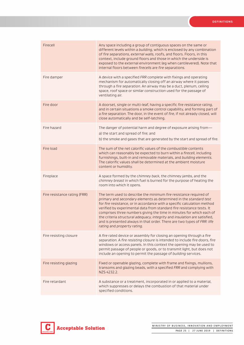
Firecell Any space including a group of contiguous spaces on the same or different levels within a building, which is enclosed by any combination of fire separations, external walls, roofs, and floors. Floors, in this context, include ground floors and those in which the underside is exposed to the external environment (eg when cantilevered). Note that internal floors between firecells are fire separations.
Fire damper A device with a specified FRR complete with fixings and operating mechanism for automatically closing off an airway where it passes through a fire separation. An airway may be a duct, plenum, ceiling space, roof space or similar construction used for the passage of ventilating air.
Fire door A doorset, single or multi-leaf, having a specific fire resistance rating, and in certain situations a smoke control capability, and forming part of a fire separation. The door, in the event of fire, if not already closed, will close automatically and be self-latching.
Fire hazard The danger of potential harm and degree of exposure arising from—
a) the start and spread of fire; and
b) the smoke and gases that are generated by the start and spread of fire.
Fire load The sum of the net calorific values of the combustible contents which can reasonably be expected to burn within a firecell, including furnishings, built-in and removable materials, and building elements. The calorific values shall be determined at the ambient moisture content or humidity.
Fireplace A space formed by the chimney back, the chimney jambs, and the chimney breast in which fuel is burned for the purpose of heating the room into which it opens.
Fire resistance rating (FRR) The term used to describe the minimum fire resistance required of primary and secondary elements as determined in the standard test for fire resistance, or in accordance with a specific calculation method verified by experimental data from standard fire resistance tests. It comprises three numbers giving the time in minutes for which each of the criteria structural adequacy, integrity and insulation are satisfied, and is presented always in that order. There are two types of FRR: life rating and property rating.
Fire resisting closure A fire rated device or assembly for closing an opening through a fire separation. A fire resisting closure is intended to include fire doors, fire windows or access panels. In this context the opening may be used to permit passage of people or goods, or to transmit light, but does not include an opening to permit the passage of building services.
Fire resisting glazing Fixed or openable glazing, complete with frame and fixings, mullions, transoms and glazing beads, with a specified FRR and complying with NZS 4232.2.
Fire retardant A substance or a treatment, incorporated in or applied to a material, which suppresses or delays the combustion of that material under specified conditions.

BUILDING CODE
CAcceptable Solution
DEFINITIONS
Fire safety systems The combination of all active and passive protection methods used in a building to—
a) warn people of an emergency; and
b) provide for safe evacuation; and
c) provide for access by, and the safety of, firefighters; and
d) restrict the spread of fire; and
e) limit the impact of fire on structural stability.
Fire separation Any building element which separates firecells or firecells and safe paths, and provides a specific fire resistance rating.
Fire shutter A fire rated device, complete with fixings and operating mechanism, for automatically closing off an opening in a fire separation or protected shaft.
Fire stop A material or method of construction used to restrict the spread of fire within or through fire separations, and having a FRR no less than that of the fire separation. Fire stops are mainly used to seal around penetrations, but can also be used to seal narrow gaps between building elements.
Fixture An article intended to remain permanently attached to and form part of a building.
Flammability index (FI) That index number for flammability, which is determined according to the standard test method for flammability of thin flexible materials.
Flue The passage through which the products of combustion are conveyed to the outside.
Flue liner Pipes or linings of fire clay, metal or fire brick that surrounds flues.
Flue system A series of interconnecting flue pipe casings which form a safe passage (flue) for conveying products of combustion from within an appliance to the outside of a building or structure.
Foamed plastics Combustible foamed plastic polymeric materials of low density (typically less than 100 kg/m3) and classified as cellular polymers which are manufactured by creating a multitude of fine void (typically 90 to 98%) distributed more or less uniformly throughout the product. Examples of foamed plastics are latex foams, polyethylene foams, polyvinyl chloride foams, expanded or extruded polystyrene foams, phenolic foams, ureaformaldehyde foams, polyurethane foams and polychloropene foams.
Group Number The classification number for a material used as a finish, surface, lining, or attachment to a wall or ceiling within an occupied space and determined according to the standard test methods for measuring the properties of lining materials. The method for determining a Group Number is described in C/VM2 Appendix A.
M I N I S T R Y O F B U S I N E S S , I N N O VAT I O N A N D E M P L O Y M E N T
PAGE 26 | 27 JUNE 2019 | DEFINITIONS

BUILDING CODE
C Acceptable Solution
DEFINITIONS
Group sleeping area A firecell containing communal sleeping accommodation for a specified number of people who may or may not be known to one another.
Handrail A rail to provide support to, or assist with the movement of a person.
Hazardous Creating an unreasonable risk to people of bodily injury or deterioration of health.
Hazardous substance Has the meaning ascribed to it by section 2 of the Hazardous Substances and New Organisms Act 1996.
Hearth The insulating floor under the fire and in front and at the sides of the fireplace.
Hold-open device A device which holds a smoke control door or fire door open during normal use, but is released by deactivating the device by an automatic fire detection system, allowing the door to close automatically under the action of a self-closing device.
Household unit a) means a building or group of buildings, or part of a building or group of buildings, that is—
i) used, or intended to be used, only or mainly for residential purposes; and
ii) occupied, or intended to be occupied, exclusively as the home or residence of not more than 1 household; but
b) does not include a hostel, boarding house, or other specialised accommodation.
HVAC An abbreviation for heating, ventilating and air-conditioning.
Insulating material A material that has a thermal conductivity of less than 0.07 W/mK.
Insulation In the context of fire protection, the time in minutes for which a prototype specimen of a fire separation, when subjected to the standard test for fire resistance, has limited the transmission of heat through the specimen.
Integrity In the context of fire protection, the time in minutes for which a prototype specimen of a fire separation, when subjected to the standard test for fire resistance, has prevented the passage of flame or hot gases. The precise meaning of integrity depends on the type of building elements being treated and how it is defined in the standard test being used.
M I N I S T R Y O F B U S I N E S S , I N N O VAT I O N A N D E M P L O Y M E N T
PAGE 27 | 5 NOVEMBER 2020 | DEFINITIONS
Amend 2Nov 2020

BUILDING CODE
CAcceptable Solution
DEFINITIONS
Intended use In relation to a building,—
a) includes any or all of the following:
i) any reasonably foreseeable occasional use that is not incompatible with the intended use;
ii) normal maintenance;
iii) activities undertaken in response to fire or any other reasonably foreseeable emergency; but
b) does not include any other maintenance and repairs or rebuilding.
Intermediate floor Any upper floor within a firecell which because of its configuration provides an opening allowing smoke or fire to spread from a lower to an upper level within the firecell.
Life rating The fire resistance rating to be applied to elements of construction that allows movement of people from their location in a building to a safe place.
Limited combustible A material that does not comply with the requirements for a non-combustible material and is classified as A2 in accordance with BS EN 13501-1.
Means of escape from fire In relation to a building that has a floor area—
a) means continuous unobstructed routes of travel from any part of the floor area of that building to a place of safety; and
b) includes all active and passive protection features required to warn people of fire and to assist in protecting people from the effects of fire in the course of their escape from the fire.
Multi-unit dwelling Applies to a building or use which contains more than one separate household or family.
Non-combustible Material either—
a) composed entirely of glass, concrete, steel, brick/block, ceramic tile, or aluminium; or
b) classified as non-combustible when tested to AS 1530.1; or
c) classified as A1 in accordance with BS EN 13501-1.
Notional boundary The boundary which for fire safety purposes, is assumed to exist between two buildings on the same property under a single land title. The notional boundary is not permitted to be located any closer than 1.0 metre to any unprotected areas within the external wall of the building that is receiving the radiation where orientated at less than 90°.
Occupant load The greatest number of people likely to occupy a particular space within a building. It is determined by:
a) dividing the total floor area by the m2 per person (occupant density) for the activity being undertaken, or
b) for sleeping areas, counting the number of sleeping (or care) spaces, or
c) for fixed seating areas, counting the number of seats.
Occupied space Any space within a building in which a person will be present from time to time during the intended use of the building.
Open path That part of an escape route (including dead ends) within a firecell where occupants may be exposed to fire or smoke while making their escape.
M I N I S T R Y O F B U S I N E S S , I N N O VAT I O N A N D E M P L O Y M E N T
PAGE 28 | 5 NOVEMBER 2020 | DEFINITIONS
Amend 2Nov 2020
Amend 2Nov 2020

BUILDING CODE
C Acceptable Solution
DEFINITIONS
Open space Land on which there are, and will be, no buildings and which has no roof over any part of it other than overhanging eaves.
Other property Any land or buildings or part of any land or buildings, that are:
a) not held under the same allotment; or
b) not held under the same ownership; and
c) includes a road.
Owner In relation to land and any buildings on the land—
a) means the person who—
i) is entitled to the rack rent from the land; or would be so entitled if the land were let to a tenant at a rack rent; and
b) includes—
i) the owner of the fee simple of the land; and
ii) for the purposes of Building Act sections 32, 44, 92, 96, 97, and 176(c), any person who has agreed in writing, whether conditionally or unconditionally, to purchase the land or any leasehold estate or interest in the land, or to take a lease of the land, and who is bound by the agreement because the agreement is still in force.
Penetration A building element passing through an opening in a fire separation. A penetration may include, but is not limited to: pipes, cables, ducts, hoses, drains, cable trays, ropes, data outlets, power outlets, hatches, glazing, structural bracing etc.
People with disabilities People whose ability to use buildings is affected by mental, physical, hearing or sight impairment.
Place of safety Either—
a) a safe place; or
b) a place that is inside a building and meet the following requirements:
i) the place is constructed with fire separations that have fire resistance sufficient to withstand burnout at the point of the fire source; and
ii) the place is in a building that is protected by an automatic fire sprinkler system that complies with NZS 4541 or NZS 4515 as appropriate to the building’s use; and
iii) the place is designed to accommodate the intended number of persons; and
iv) the place is provided with sufficient means of escape to enable the intended number of persons to escape to a safe place that is outside a building.
Primary element A building element providing the basic loadbearing capacity to the structure, and which if affected by fire may initiate instability or premature structural collapse.
Property rating The fire resistance rating to be applied to elements of construction that allows for protection of other property.
Protected shaft A space, other than a safe path, enclosed by fire separations or external walls used to house building services, lifts, or conveyors which pass from one firecell to another.
Railway line Has the meaning ascribed to it by section 4 of the Railways Act 2005.
M I N I S T R Y O F B U S I N E S S , I N N O VAT I O N A N D E M P L O Y M E N T
PAGE 29 | 27 JUNE 2019 | DEFINITIONS

BUILDING CODE
CAcceptable Solution
DEFINITIONS
Relevant boundary The boundary of an allotment that is other property in relation to the building in question and from which is measured the separation between the building and that other property; and for the external wall of any building, the relevant boundary is the nearest of—
a) a boundary of a freehold allotment, except that if the other property is a road, railway line, or public open space, the relevant boundary is the boundary on the far side of that other property; or
b) a boundary of a cross-lease or a company lease or a licence, except that if the other property is open space to which the lessee or licencee of the building in question has an exclusive right of access and occupation or to which 2 or more occupiers of the building in question have rights of access and occupation, the relevant boundary is the boundary on the far side of that other property; or
c) a boundary shown on a unit plan (but excluding a boundary between a principal unit and its accessory unit), except that if the other property is open space and is common property, the relevant boundary is the boundary on the far side of that other property.
Refer also to notional boundary for buildings on the same property under a single land title.
Risk group The classification of a building or firecells within a building according to the use to which it is intended to be put.
Road Has the meaning ascribed to it by section 315 of the Local Government Act 1974 and includes a public place and also includes a motorway.
Safe path That part of an exitway which is protected from the effects of fire by fire separations, external walls, or by distance when exposed to open air.
Safe place A place, outside of and in the vicinity of a single building unit, from which people may safely disperse after escaping the effects of a fire. It may be a place such as a street, open space, public space or an adjacent building unit.
Safety glass Means glass so treated or combined with other materials as to reduce the likelihood of injury to persons when it is cracked or broken.
Secondary element A building element not providing load bearing capacity to the structure and if affected by fire, instability or collapse of the building structure will not occur.
Smokecell A space within a building which is enclosed by an envelope of smoke separations, or external walls, roofs, and floors.
Smoke control door A doorset that complies with Appendix C, C6.1.2 of this Acceptable Solution.
Smoke damper A fire damper whose closing action is initiated by the detection of smoke.
Smoke lobby That portion of an escape route within a firecell that precedes a safe path or an escape route through an adjoining building which is protected from the effects of smoke by smoke separations.
M I N I S T R Y O F B U S I N E S S , I N N O VAT I O N A N D E M P L O Y M E N T
PAGE 30 | 5 NOVEMBER 2020 | DEFINITIONS
Amend 2Nov 2020
BUILDING CODE
C Acceptable Solution
DEFINITIONS
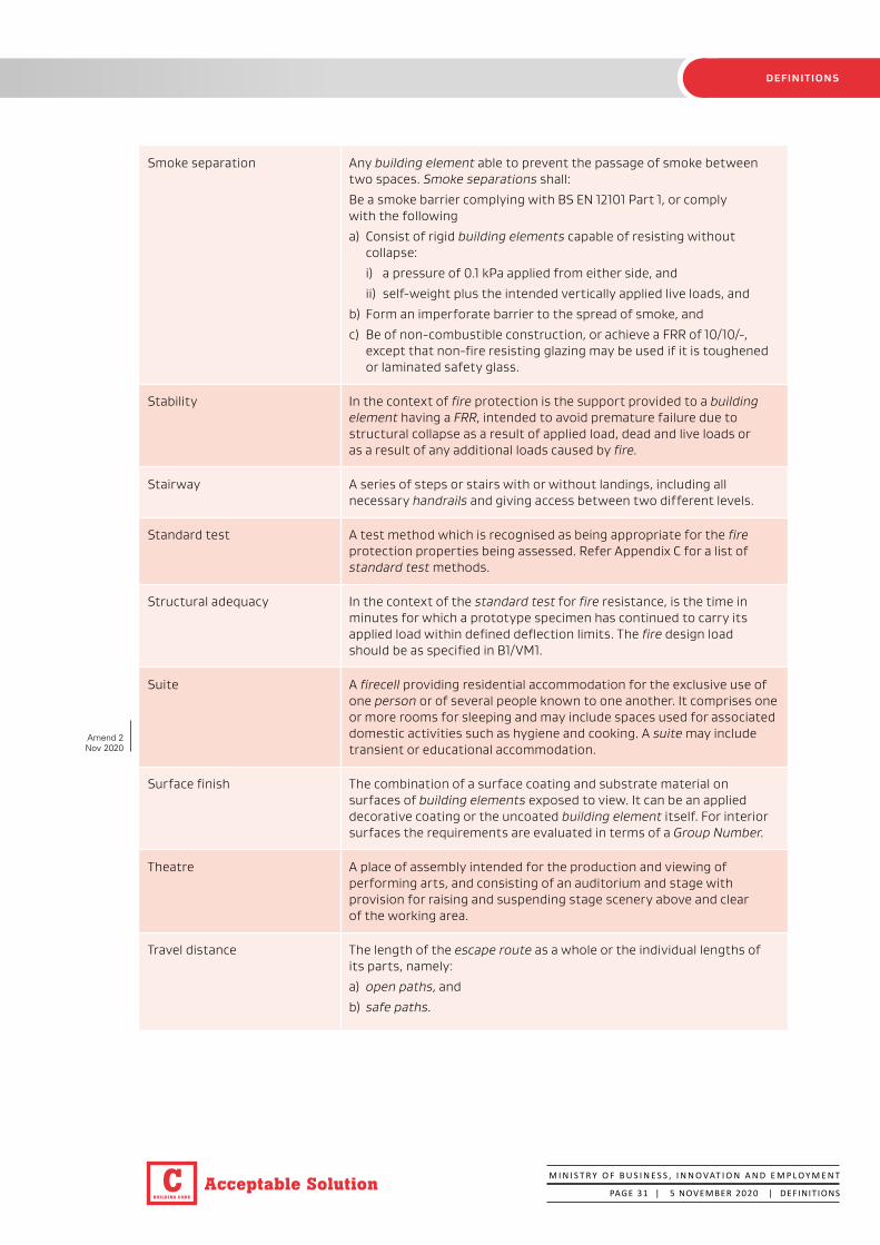
Smoke separation Any building element able to prevent the passage of smoke between two spaces. Smoke separations shall:
Be a smoke barrier complying with BS EN 12101 Part 1, or comply with the following
a) Consist of rigid building elements capable of resisting without collapse:
i) a pressure of 0.1 kPa applied from either side, and
ii) self-weight plus the intended vertically applied live loads, and
b) Form an imperforate barrier to the spread of smoke, and
c) Be of non-combustible construction, or achieve a FRR of 10/10/-, except that non-fire resisting glazing may be used if it is toughened or laminated safety glass.
Stability In the context of fire protection is the support provided to a building element having a FRR, intended to avoid premature failure due to structural collapse as a result of applied load, dead and live loads or as a result of any additional loads caused by fire.
Stairway A series of steps or stairs with or without landings, including all necessary handrails and giving access between two different levels.
Standard test A test method which is recognised as being appropriate for the fire protection properties being assessed. Refer Appendix C for a list of standard test methods.
Structural adequacy In the context of the standard test for fire resistance, is the time in minutes for which a prototype specimen has continued to carry its applied load within defined deflection limits. The fire design load should be as specified in B1/VM1.
Suite A firecell providing residential accommodation for the exclusive use of one person or of several people known to one another. It comprises one or more rooms for sleeping and may include spaces used for associated domestic activities such as hygiene and cooking. A suite may include transient or educational accommodation.
Surface finish The combination of a surface coating and substrate material on surfaces of building elements exposed to view. It can be an applied decorative coating or the uncoated building element itself. For interior surfaces the requirements are evaluated in terms of a Group Number.
Theatre A place of assembly intended for the production and viewing of performing arts, and consisting of an auditorium and stage with provision for raising and suspending stage scenery above and clear of the working area.
Travel distance The length of the escape route as a whole or the individual lengths of its parts, namely:
a) open paths, and
b) safe paths.
M I N I S T R Y O F B U S I N E S S , I N N O VAT I O N A N D E M P L O Y M E N T
PAGE 31 | 5 NOVEMBER 2020 | DEFINITIONS
Amend 2Nov 2020

BUILDING CODE
CAcceptable Solution
DEFINITIONS
Unprotected area In relation to an external wall of a building, means:
a) Any part of the external wall which is not fire rated or has less than the required FRR, and
b) Any part of the external wall which has combustible material more than 1.0 mm thick attached or applied to its external face, whether for cladding or any other purpose.
Unprotected areas include non-fire rated windows, doors, or other openings, and non-fire rated external wall construction.
Wharenui A communal meeting house having a large open floor area used for both assembly and sleeping in the traditional Māori manner.
M I N I S T R Y O F B U S I N E S S , I N N O VAT I O N A N D E M P L O Y M E N T
PAGE 32 | 5 NOVEMBER 2020 | DEFINITIONS
Amend 2Nov 2020

BUILDING CODE
C Acceptable Solution
GENERAL
M I N I S T R Y O F B U S I N E S S , I N N O VAT I O N A N D E M P L O Y M E N T
PAGE 33 | 27 JUNE 2019 | PA R T 1
Part 1: General
CONTENTS
1.1 Introduction and scope
1.2 Using this Acceptable Solution
1.3 Alterations to buildings
1.4 Calculating occupant loads
1.1 Introduction and scope
This Acceptable Solution is one of three Acceptable Solutions that provide a means of establishing compliance with NZBC Clauses C1 to C6 Protection from Fire. It can be used for the building activities covered by risk groups specified in Paragraph 1.1.1 and described in Table 1.1.
For risk group SH, please refer to Acceptable Solution C/AS1.
For backcountry huts, please refer to Acceptable Solution BCH/AS1.
Where a specific risk group (or risk groups) is mentioned in a subheading and/or within the text of a paragraph, that requirement applies only to the specified risk group(s), and does not apply to other risk groups.
Words in italic are defined at the front of this document.
Appendices to this Acceptable Solution are part of, and have equal status to, the Acceptable Solution.
Figures and risk group icons are informative only; the wording of the paragraphs takes precedence.
Risk group icons
SH SM SI CA WB WS VP
Solid red circlesApplies to particular risk group requirements
SH SM SI CA WB WS VP
White circles with red barRequirement excludes the particular risk group

BUILDING CODE
CAcceptable Solution
GENERAL
M I N I S T R Y O F B U S I N E S S , I N N O VAT I O N A N D E M P L O Y M E N T
PAGE 34 | 5 NOVEMBER 2020 | PA R T 1
Table 1.1
Risk groups: scope and limitations
Risk group Applies to
C/AS1SH* Buildings with
sleeping (residential) and outbuildings
(Out of scope for this Acceptable Solution)
Detached dwellings with a single household unit such as: stand-alone houses
Low-rise multi-unit dwellings where each household unit has its own escape route that is independent of all other household units such as: Attached townhouses. Stacked household units where there is no more than one household unit above another with each household unit having a single storey and an escape height less than 4.0 m.
Detached dwellings where fewer than six people (not including members of the residing family) pay for accommodation such as: boarding houses, homestays, bed and breakfast.
Outbuildings.
Acc
epta
ble
Solu
tion
C/A
S2
SM Sleeping (non-institutional)
Permanent accommodation such as: Apartment buildings and other buildings which consist of more than one household unit (other than low-rise multi-unit dwellings in the scope of risk group SH).
Transient accommodation such as: Hotels, motels, serviced apartments, hostels, backpackers, cabins at holiday parks. Buildings where six or more people pay for accommodation (such as boarding houses/homestays/ bed and breakfast). Wharenui and other community sleeping spaces such as halls (even if used occasionally). Sheltered housing such as refuges, reintegration for prisoners, homeless shelters etc.
Educational accommodation such as: University halls of residence, school boarding hostels etc.
SI Care or detention Care activities such as: Institutions, hospitals including outpatients and day procedures (excluding special care facilities such as operating theatres, intensive care units, prisons, delivery and recovery rooms and hyperbaric chambers or other such places that require stay in place strategies). Aged care facilities. Residential care in institutions, hospices. Medical day treatment: i.e. medical centres and dental practices using sedation or treatment rooms where people are unable to self-evacuate without assistance; e.g. for dialysis or chemotherapy. Care in the community houses and homes.
Detention facilities (excluding prisons) such as: Police stations, court buildings and hospitals with detention facilities.
CA Public access and educational facilities
Crowd activities such as: Halls, theatres and cinemas. Recreation and event centres (including tiered seating for up to 2000 people and with any primary egress for more than 100 people at the level of the playing surface). Educational institutions without sleeping including schools and early childhood centres. Churches and other places of worship. Restaurants and cafes, shops and shopping malls. Exhibition, retail areas including car showrooms and trade fair space. Public libraries with less than 2.4 m storage height. Spaces for viewing open air activities (does not include spaces below a grandstand), open grandstands, roofed but unenclosed grandstand, uncovered fixed seating).
Personal service activities such as: Dentists, doctors (except as included within risk group SI), banks, beautician and hairdressing salons.
WB Business, commercial and low level storage
Professional activities such as: Offices (including professional services such as law and accountancy practices). Laboratories, workshops (including mechanics workshops). May contain storage with a capable height of storage of less than 3.0 m.
Industrial activities such as: Factories, processing and manufacturing plants (excluding foamed plastics) with a capable height of storage of less than 3.0 m.
Storage activities such as: Buildings or parts of buildings capable of storage no more than 5.0 m in height. Warehouses and storage buildings (other than those listed above), capable of storage more than 5.0 m in height, but a height to the apex no greater than 8.0 m and total floor area of no more than 4200 m2. Temperature controlled storage with a capable height of storage of less than 3.0 m, other than some limited areas in processing areas, or up to a maximum area of 500 m2 with a maximum capable of storage height of 5.0 m.
Intermittently occupied buildings (other than outbuildings) such as: Light aircraft hangers, buildings containing fixed plant and or fixed machinery and spray painting operations, whether or not in a spray booth.
Errata 1 Oct 2019
Amend 2Nov 2020
Amend 2Nov 2020

BUILDING CODE
C Acceptable Solution
GENERAL
M I N I S T R Y O F B U S I N E S S , I N N O VAT I O N A N D E M P L O Y M E N T
PAGE 35 | 27 JUNE 2019 | PA R T 1
Table 1.1
Risk groups: scope and limitations
Risk group Applies to
Acc
epta
ble
Solu
tion
C/
AS2
WS High level storage or potential for fast fire growth
Storage activities such as: Warehouses with a capable height of storage of over 5.0 m or over 8.0 m to the apex and total floor area greater than 4200 m2. Temperature controlled storage outside of the scope of risk group WB.
Service activities such as: Trading and bulk retail wholesalers with a storage height greater than 3.0 m. Supermarkets with shelving over 3.0 m in height. Exhibition, retail areas and trade fair space with a storage height greater than 3.0 m.
VP Vehicle storage and parking
Vehicle parking – within a building or a separate building including:
Car parking buildings. Vehicle parking or stacking within buildings. Goods vehicle parking. Service vehicle and unloading areas. Car storage warehouses.
Note:
* Risk group SH is outside the scope of this Acceptable Solution. Refer to C/AS1.
Scope
1.1.1 The scope of this Acceptable Solution is restricted to all risk groups listed in Table 1.1 except for risk group SH (refer to C/AS1). It covers buildings or parts of buildings where people:
a) Sleep (SM), and
b) Are unable to self-evacuate without assistance through requiring special care or treatment, or they are restrained, or their liberties are restricted (SI), and
c) Congregate, participate in group activities or where professional services or retail are provided (CA), and
d) Work (WB), and
e) Store goods and other materials (WS), and
f) Park vehicles (VP).
These activities are described in Table 1.1.
Outside the scope of this Acceptable Solution
1.1.2 Buildings with complex features are outside the scope of this Acceptable Solution. Complex features include:
a) Atriums, and
b) Intermediate floors, other than limited area intermediate floors, and
c) Operating theatres, intensive care units, hyperbaric chambers, delivery rooms, and recovery rooms (SI), and
d) Recreation and event centres (with tiered seating for more than 2000 people) (CA), and
e) Buildings more than 20 storeys high, and
f) Prison buildings.
Buildings that have features for which solutions are not provided within this Acceptable Solution are also deemed to be complex.
1.1.3 If the Acceptable Solution cannot be followed in full, use Verification Method C/VM2 or an alternative solution to demonstrate compliance.
1.1.4 Other than where permitted for risk group SI and for early childhood centres, this Acceptable Solution allows for an ‘all out’ evacuation strategy. It does not provide features to facilitate a delayed evacuation strategy.
SH
SI
CA
WB
WS
VP
SM
SI
CA

BUILDING CODE
CAcceptable Solution
GENERAL
M I N I S T R Y O F B U S I N E S S , I N N O VAT I O N A N D E M P L O Y M E N T
PAGE 36 | 5 NOVEMBER 2020 | PA R T 1
1.1.5 Risk group SI invariably requires a fire safety strategy involving delayed initiation of evacuation and movement to a place of safety within the building. However, this Acceptable Solution does not provide for building features that would be required for a stay-in-place strategy. This applies to activities such as:
a) Operating theatres, and
b) Intensive care units, and
c) Hyperbaric chambers, and
d) Delivery rooms, and
e) Recovery rooms.
The control of hazardous substances is not covered by this Acceptable Solution
1.1.6 This Acceptable Solution does not provide for any use, storage or processing of hazardous substances. Compliance with NZBC Clause F3, the Hazardous Substances and New Organisms Act 1996, and the Health and Safety at Work (Hazardous Substances) Regulations 2017 shall also be ensured where applicable in addition to the requirements of this Acceptable Solution.
1.2 Using this Acceptable Solution
1.2.1 The process for using this Acceptable Solution shall be as follows.
Step 1: Determine which risk group applies
a) Determine the risk group for each of the activities carried out in the building (refer to Table 1.1 and Paragraph 1.1.1). If the activity is not listed explicitly, choose the nearest suitable risk group.
b) If there is more than one risk group for a firecell, determine its primary risk group (see Paragraph 1.2.2: this is the one with the most onerous fire safety requirements).
c) Apply this Acceptable Solution for any firecell by following steps 2 and 3.
d) Then apply the relevant parts of this Acceptable Solution for firecells.
Step 2: Determine the parameters for the various risk groups
a) Establish the relevant building measurements (these will include building height, floor area, wall openings and distances to relevant boundaries).
b) Work out the occupant loads for the relevant occupied spaces (refer to Paragraph 1.4).
Step 3: Satisfy the fire safety requirements
Satisfy the fire safety requirements of this Acceptable Solution (refer to Parts 2-7), based on the occupant loads and on the building’s dimensions and features where required.
Primary risk groups
1.2.2 If a building contains a number of different activities which individually may be categorised in different risk groups, the risk group designated for a particular firecell within a building shall be that of the primary risk group. The primary risk group shall be that one within the firecell that has the most onerous fire safety requirements. Other risk groups may be able to be incorporated within the same space provided these are ancillary to, and support, the primary risk groups.
1.2.3 Depending on the particular building and the uses or activities within that building, there may be several primary risk groups, with one or more on each floor.
1.3 Alterations to buildings
1.3.1 This Acceptable Solution may be used to determine the compliance of building work (in relation to an existing building).
SI
Amend 2Nov 2020

BUILDING CODE
C Acceptable Solution
GENERAL
M I N I S T R Y O F B U S I N E S S , I N N O VAT I O N A N D E M P L O Y M E N T
PAGE 37 | 27 JUNE 2019 | PA R T 1
1.4 Calculating occupant loads
Occupant load
1.4.1 The occupant load shall be determined from the risk group and number of people in each space of the building. The occupant load may need to be evaluated not only for each risk group but also for:
a) A space or open floor area involving one or more activities, and
b) A floor containing more than one risk group, and
c) A single firecell, and
d) Each floor within a firecell.
1.4.2 Occupant loads shall be calculated from the occupant densities given in Table 1.2 based on the floor area of the part of the building housing the activity. The occupant densities in Table 1.2 already allow for a proportion of the floor area appropriate to the activity being occupied by furniture, partitions, fixtures and associated equipment. If a building space has alternative activity uses, the activity having the greatest occupant density shall be used. If an activity is not specifically described in Table 1.2, the nearest reasonable description shall be used.
1.4.3 Duplication shall be avoided by:
a) Ensuring that, where people may be involved in more than one activity, they are counted only once, and
b) Not including an occupant load for exitways, or for the occupant load determined for areas such as lift lobbies or sanitary facilities that are used intermittently by people already counted elsewhere in the building.
Fixed seating
1.4.4 Occupant load assessment shall take account of the actual arrangement and number of seats for fixed seating (see Paragraph 3.7.4). Where additional floor area abuts the fixed seating, additional occupants are permitted in that floor area based on standing space density, provided the escape route is not obstructed.
Bed spaces
.. The requirements of this Acceptable Solution account for the fact that other people may be present in the building or firecell and additional calculations are not required when an occupant load is derived by bed spaces (i.e. for risk groups SM and SI).
1.4.6 For the purposes of risk group SI the term ‘bed’ means the number of people that are under care or detention. It can include people on:
a) Beds, or
b) Recliner or lounge chairs, or
c) Dentist chairs, or
d) Treatment tables, or
e) Any other furniture where an occupant may be for a period of treatment, in care or detention.
Justification for exceptions
1.4.7 If, in a particular situation, the occupant load derived from Table 1.2 is clearly more than that which will occur, the basis of any proposal for a lesser occupant load shall be substantiated to the building consent authority.
..8 If the maximum occupant load is greater than that calculated from Table 1.2, the higher number shall be used as the basis for the fire safety design and will need to be justified to the building consent authority.
SI

BUILDING CODE
CAcceptable Solution
GENERAL
M I N I S T R Y O F B U S I N E S S , I N N O VAT I O N A N D E M P L O Y M E N T
PAGE 38 | 27 JUNE 2019 | PA R T 1
Table 1.2 Occupant densities
Activity
Aircraft hangars 50
Airports – baggage areas 2
– waiting areas, check in 1.4
– terminal space 10
Area without seating or aisles 1
Art galleries, museums 4
Bar sitting areas 1
Bar standing areas 0.5
Bleachers, pews or bench-type seating 0.45 linear m per person
Boiler rooms, plant rooms 30
Bulk storage including racks and shelves 100
Bulk retail (trading stores, supermarkets etc) 5
Call centres 7
Care and detention Bed spaces, see Paragraph 1.4.6
Classrooms 2
Commercial kitchens 10
Commercial laboratories, laundries 10
Computer server rooms 25
Consulting rooms (doctors, dentists, beauty therapy) 5
Dance floors 0.6
Day care centres 4
Dining, restaurant and cafeteria spaces 1.25
Early childhood centres Based on Education (Early Childhood Services) Regulations 2008 plus the number of staff
Exhibition areas, trade fairs 1.4
Fitness centres/weights rooms 5
Gaming, casino areas 1
Heavy industry 30
Indoor games areas, bowling alleys 10
Interview rooms 5
Libraries: stack areas 10
Libraries: other areas 7
Lobbies and foyers 1
Mall areas used for assembly uses 1
Manufacturing and process areas 10
Meeting rooms 2.5
Office spaces 10
Occupancy density (m2/ person)

BUILDING CODE
C Acceptable Solution
GENERAL
M I N I S T R Y O F B U S I N E S S , I N N O VAT I O N A N D E M P L O Y M E N T
PAGE 39 | 27 JUNE 2019 | PA R T 1
Table 1.2 Occupant densities
Activity
Parking buildings, garages 50
Personal service facilities 5
Reading or writing rooms and lounges 2
Retail spaces and pedestrian circulation areas including malls and arcades 3.5
Retail spaces for furniture, floor coverings, large appliances, building supplies and Manchester
10
Reception areas 10
Showrooms 5
Sleeping non institutional Bed spaces
Space with fixed seating As number of seats
Space with loose seating 0.8
Space with loose seating and tables 1.1
Sports halls 3
Stadiums and grandstands 0.6
Staffrooms and lunchrooms 5
Stages for theatrical performances 0.8
Standing space 0.4
Swimming pools (water surface area) 5
Swimming pools: surrounds and seating 3
Teaching laboratories 5
Technology classrooms (e.g. woodwork, metalwork, food science and sewing) 10
Workrooms, workshops 5
Occupancy density (m2/ person)
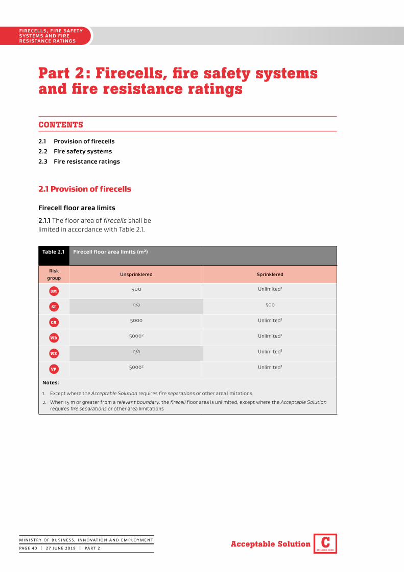
BUILDING CODE
CAcceptable Solution
FIRECELLS, FIRE SAFETY SYSTEMS AND FIRE RESISTANCE RATINGS
M I N I S T R Y O F B U S I N E S S , I N N O VAT I O N A N D E M P L O Y M E N T
PAGE 40 | 27 JUNE 2019 | PA R T 2
Part 2: Firecells, fire safety systems and fire resistance ratings
CONTENTS
2.1 Provision of firecells
2.2 Fire safety systems
2.3 Fire resistance ratings
2.1 Provision of firecells
Firecell floor area limits
2.1.1 The floor area of firecells shall be limited in accordance with Table 2.1.
Table 2.1 Firecell floor area limits (m2)
Risk group
Unsprinklered Sprinklered
SM 500 Unlimited1
SI n/a 500
CA 5000 Unlimited1
WB 50002 Unlimited1
WS n/a Unlimited1
VP 50002 Unlimited1
Notes:
1. Except where the Acceptable Solution requires fire separations or other area limitations
2. When 15 m or greater from a relevant boundary, the firecell floor area is unlimited, except where the Acceptable Solution requires fire separations or other area limitations

BUILDING CODE
C Acceptable Solution
FIRECELLS, FIRE SAFETY SYSTEMS AND FIRE
RESISTANCE RATINGS
M I N I S T R Y O F B U S I N E S S , I N N O VAT I O N A N D E M P L O Y M E N T
PAGE 41 | 5 NOVEMBER 2020 | PA R T 2
2.2 Fire safety systems
2.2.1 Fire safety system types, as defined in Table 2.2, shall be provided throughout firecells and be as specified in:
• Table 2.2a for risk groups SM and SI, and
• Table 2.2b for risk group CA, and
• Table 2.2c for risk groups WB and WS, and
• Table 2.2d for risk group VP.
A direct connection to Fire and Emergency New Zealand is not required if automatic heat or smoke detection systems are provided in addition to the systems required by this Acceptable Solution.
Additional requirements for early childhood centres
2.2.2 In addition to Paragraph 2.2.1, the fire safety systems required for firecells in early childhood centres shall be as follows:
a) In single storey early childhood centres, dedicated sleeping areas shall be protected with supplementary smoke detectors. The alarm system and any smoke detection system shall comply with NZS 4512.
b) Where the escape height of the early childhood centre is greater than 2.0 m:
i) a Type 7 system shall be installed throughout the building, and
ii) at least two separate places of safety shall be provided, and
iii) each place of safety shall be separated with fire separations designed to the property rating and have direct access to a safe path or final exit.
Buildings containing more than one firecell
2.2.3 Where there is more than one firecell the following design sequence shall be used to determine the fire safety systems for other firecells in the building (see Figure 2.1).
Step 1 Determine the risk groups associated with each firecell within the building (refer Table 1.1 and Paragraphs 1.2.1 and 1.2.2).
Step 2 Determine the escape height in metres of each firecell.
Step 3 Determine the occupant load for each firecell in accordance with Paragraph 1.4.
Step 4 Taking into consideration the notes within Tables 2.2a, 2.2b, 2.2c and 2.2d and Paragraph 2.2.2 determine the fire safety systems required to protect each risk group.
Step 5 For each risk group, insert the fire safety system ascertained in Step 4 into Table 2.3 column 1 and determine the fire safety system for the other risk groups in the building from Table 2.3 column 2.
2.2.4 For risk group VP firecells that require a fire sprinkler system (refer to Table 2.2d), the fire sprinkler system does not need to be extended throughout the remainder of the building where the risk group VP firecells are fire separated from the adjacent firecells. The fire separation between adjacent firecells is required to be provided with the greater of the property rating of the adjacent firecells (refer to Table 2.4).
Step 6 Based on the fire safety systems ascertained in Step 5, determine the most onerous requirements from Tables 2.2a, 2.2b, 2.2c, 2.2d and 2.3.
CA
WB WS
VP
SM SI
VP
CA
Amend 2Nov 2020
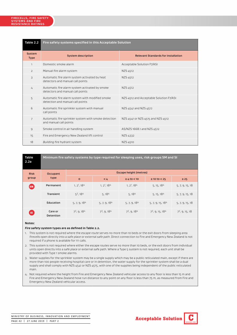
BUILDING CODE
CAcceptable Solution
FIRECELLS, FIRE SAFETY SYSTEMS AND FIRE RESISTANCE RATINGS
M I N I S T R Y O F B U S I N E S S , I N N O VAT I O N A N D E M P L O Y M E N T
PAGE 42 | 27 JUNE 2019 | PA R T 2
Table 2.2 Fire safety systems specified in this Acceptable Solution
System Type
System description Relevant Standards for installation
1 Domestic smoke alarm Acceptable Solution F7/AS1
2 Manual fire alarm system NZS 4512
3 Automatic fire alarm system activated by heat detectors and manual call points
NZS 4512
4 Automatic fire alarm system activated by smoke detectors and manual call points
NZS 4512
5 Automatic fire alarm system with modified smoke detection and manual call points
NZS 4512 and Acceptable Solution F7/AS1
6 Automatic fire sprinkler system with manual call points
NZS 4541 and NZS 4512
7 Automatic fire sprinkler system with smoke detection and manual call points
NZS 4541 or NZS 4515 and NZS 4512
9 Smoke control in air handling system AS/NZS 1668.1 and NZS 4512
15 Fire and Emergency New Zealand lift control NZS 4332
18 Building fire hydrant system NZS 4510
Table 2.2a
Minimum fire safety systems by type required for sleeping uses, risk groups SM and SI
Risk group
Occupant type
Escape height (metres)
0 < 4 ≥ 4 to < 10 ≥ 10 to < 25 ≥ 25
SM Permanent 1, 21, 184 1, 21, 184 1, 21, 184 5, 15, 184 5, 7, 9, 15, 18
Transient 52, 184 5, 184 5, 184 5, 15, 184 5, 7, 9, 15, 18
Education 5, 7, 9, 184 5, 7, 9, 184 5, 7, 9, 184 5, 7, 9, 15, 184 5, 7, 9, 15, 18
SI Care or Detention
73, 9, 184 73, 9, 184 73, 9, 184 73, 9, 15, 184 73, 9, 15, 18
Notes:
Fire safety system types are as defined in Table 2.2.
1. This system is not required where the escape route serves no more than 10 beds or the exit doors from sleeping area firecells open directly into a safe place or external safe path. Direct connection to Fire and Emergency New Zealand is not required if a phone is available for 111 calls.
2. This system is not required where either the escape routes serve no more than 10 beds, or the exit doors from individual units open directly into a safe place or external safe path. Where a Type 5 system is not required, each unit shall be provided with Type 1 smoke alarms.
3. Water supplies for the sprinkler system may be a single supply which may be a public reticulated main, except if there are more than 100 people receiving hospital care or in detention, the water supply for the sprinkler system shall be a dual supply and shall comply with NZS 4541 or NZS 4515, with one of the supplies being independent of the public reticulated main.
4. Not required where the height from Fire and Emergency New Zealand vehicular access to any floor is less than 15 m and Fire and Emergency New Zealand hose run distance to any point on any floor is less than 75 m, as measured from Fire and Emergency New Zealand vehicular access.

BUILDING CODE
C Acceptable Solution
FIRECELLS, FIRE SAFETY SYSTEMS AND FIRE
RESISTANCE RATINGS
M I N I S T R Y O F B U S I N E S S , I N N O VAT I O N A N D E M P L O Y M E N T
PAGE 43 | 27 JUNE 2019 | PA R T 2
Table 2.2b
Minimum fire safety systems by type required for crowd uses, risk group CA1
Risk group
Occupant load
Escape height (metres)
0 < 4 ≥ 4 to < 10 ≥ 10 to < 25 ≥ 25
CA < 100 22,3, 186 23, 186 44,5, 9, 186 44,5, 9, 15, 186 7, 9, 15, 18
100 to 250 23, 186 23, 186 44,5, 9, 186 44,5, 9, 15, 186 7, 9, 15, 18
251 to ≤ 1000 44,5, 186 44,5, 186 44,5, 9, 186 44,5, 9, 15, 186 7, 9, 15, 18
> 1000 7, 9, 186 7, 9, 186 7, 9, 186 7, 9, 15, 186 7, 9, 15, 18
Notes:
Fire safety system types are as defined in Table 2.2.
1. Refer to Paragraph 2.2.2 for additional requirements that apply to early childhood centres.
2. This system is not required in single level buildings where the escape route serves no more than 50 people.
3. Provided the use is not as a cinema or theatre, a Fire and Emergency New Zealand connection is not required if a phone is available for 111 calls.
4. Where the environment is challenging for smoke detection, the Type 4 system may be substituted with a Type 3 system with supplementary smoke detection.
5. May be substituted with a Type 6 system where the building’s occupant load does not exceed 500, each floor is a firecell, intermediate floors comply with Paragraph 4.13.4, and there are no sleeping area firecells within the building.
6. Not required where the height from Fire and Emergency New Zealand vehicular access to any floor is less than 15 m and Fire and Emergency New Zealand hose run distance to any point on any floor is less than 75 m, as measured from Fire and Emergency New Zealand vehicular access.
Errata 1 Oct 2019

BUILDING CODE
CAcceptable Solution
FIRECELLS, FIRE SAFETY SYSTEMS AND FIRE RESISTANCE RATINGS
M I N I S T R Y O F B U S I N E S S , I N N O VAT I O N A N D E M P L O Y M E N T
PAGE 44 | 27 JUNE 2019 | PA R T 2
Table 2.2c
Minimum fire safety systems by type required for working uses, risk groups WB and WS
Risk group
Occupant load
Escape height (metres)
0 < 4 ≥ 4 to < 10 ≥ 10 to < 25 ≥ 25
WB < 100 21,2,3, 187 22, 3, 187 44,5, 9, 187 44,5, 9, 15, 187 7, 9, 15, 18
100 to 250 44,5,6, 187 44,5,6, 187 44,5, 9, 187 44,5, 9, 15, 187 7, 9, 15, 18
251 to ≤ 1000 44,5,6, 187 44,5,6, 187 44,5, 9, 187 44,5, 9, 15, 187 7, 9, 15, 18
> 1000 7, 9, 187 7, 9, 187 7, 9, 187 7, 9, 15, 187 7, 9, 15, 18
WS ≤ 1000 6, 187 6, 187 6, 187 6, 15, 187 6, 15, 18
> 1000 7, 187 7, 187 7, 187 7, 15, 187 7, 15, 18
Notes:
Fire safety system types are as defined in Table 2.2.
1. This system is not required in single level buildings (excluding storage buildings with a storage height greater than 3.0 m) where the escape route serves no more than 50 people.
2. A Type 3 system is required where the storage height exceeds 3.0 m.
3. A Fire and Emergency New Zealand connection is not required if a phone is available for 111 calls.
4. Where the environment is challenging for smoke detection, the Type 4 system may be substituted with a Type 3 system with supplementary smoke detection.
5. May be substituted with a Type 6 system where the building’s occupant load does not exceed 500, each floor is a firecell, intermediate floors comply with Paragraph 4.13.4, and there are no sleeping area firecells within the building.
6. A Type 3 system is permitted to be provided in firecells used for storage where the storage height is over 3.0 m.
7. Not required where the height from Fire and Emergency New Zealand vehicular access to any floor is less than 15 m and Fire and Emergency New Zealand hose run distance to any point on any floor is less than 75 m, as measured from Fire and Emergency New Zealand vehicular access.
Table 2.2d
Minimum fire safety systems by type required for vehicle parking, risk group VP
Risk group
Escape height (metres) Vehicle stacker
< 10 ≥ 10
VP 21,2,3, 184 33, 15, 184 6, 184
Notes:
Fire safety system types are as defined in Table 2.2.
1. This system is not required if there are fewer than 50 occupants and fewer than 10 vehicles.2. If risk group VP is within a building that is protected with an automatic fire alarm system, the risk group VP firecell
must have at the minimum a Type 3 system.3. This need not be connected to Fire and Emergency New Zealand.4. Not required where the height from Fire and Emergency New Zealand vehicular access to any floor is less than 15 m and Fire
and Emergency New Zealand hose run distance to any point on any floor is less than 75 m, as measured from Fire and Emergency New Zealand vehicular access.
Errata 1 Oct 2019

BUILDING CODE
C Acceptable Solution
FIRECELLS, FIRE SAFETY SYSTEMS AND FIRE
RESISTANCE RATINGS
M I N I S T R Y O F B U S I N E S S , I N N O VAT I O N A N D E M P L O Y M E N T
PAGE 45 | 27 JUNE 2019 | PA R T 2
Table 2.3 Required types of fire safety systems for other firecells within the building Read this table in conjunction with Paragraph 2.2.3
Column 1 Column 2
Primary risk group and alarm type required by Tables 2.2a, 2.2b, 2.2c
and 2.2d
Minimum type required within other firecells on the same or other floors within the building
SM CA WB VP
SM
1, 2 1, 2 41 41 3
5 5 41 41 3
7 7 71 71 62
SI 7 5, 7 7 7 6
CA 2 23 2 2 2
3 33 3 3 3
4 5 41 41 3
6 5, 7 6 6 62
7 5, 7 71 71 62
WB 2 23 2 2 2
3 33 3 3 3
4 5 41 41 3
6 5, 7 6 6 62
7 5, 7 71 71 62
WS 6 5, 7 6 6 62
7 5, 7 71 71 62
VP 2 23 2 2 2
3 33 3 3 3
6 5, 7 61 61 6
Notes:
The systems derived from this table show the minimum type of systems required as dictated by other risk groups within thebuilding. Please read this table in conjunction with Tables 2.2a, 2.2b, 2.2c and 2.2d when defining the systems required within the building.1. Can be changed from a Type 4 to Type 3 system, or from a Type 7 to Type 6 system if the firecell is challenging
for smoke detection where permitted in Tables 2.2b or 2.2c.2. Can be changed to a Type 3 if the risk group VP firecell is fire separated from the remainder of the building by the
building's property rating in accordance with Paragraph 2.3.3. Refer to Table 2.2a for additional requirements system to be provided within risk group SM.
3

BUILDING CODE
CAcceptable Solution
FIRECELLS, FIRE SAFETY SYSTEMS AND FIRE RESISTANCE RATINGS
M I N I S T R Y O F B U S I N E S S , I N N O VAT I O N A N D E M P L O Y M E N T
PAGE 46 | 27 JUNE 2019 | PA R T 2
Figure 2.1 Fire safety systems throughout a building Paragraph 2.2.3

BUILDING CODE
C Acceptable Solution
FIRECELLS, FIRE SAFETY SYSTEMS AND FIRE
RESISTANCE RATINGS
M I N I S T R Y O F B U S I N E S S , I N N O VAT I O N A N D E M P L O Y M E N T
PAGE 47 | 27 JUNE 2019 | PA R T 2
More than one risk group on a floor
2.2.5 If there is more than one risk group on one floor level, the fire safety requirements will depend on whether the risk groups occupy the same firecell, or whether the floor is divided by fire separations into different firecells.
2.2.6 Where fire separations are not needed between different risk groups on the same floor level, the fire safety systems adopted for the firecell shall be those of the primary risk group (as defined in Paragraph 1.2.2).
Same risk group on different floors
2.2.7 Where firecells containing the same risk group occur at different levels in the same building, the fire safety systems for the firecell having the most onerous requirements shall be applied to all firecells of that risk group.
Activation of emergency warning systems
2.2.8 The alarm systems required in a building shall be configured to alert all building occupants in the event of fire. This does not apply to the activation of the local smoke detection component of a Type 5 system.
2.2.9 In risk group SI alerting all building occupants in the event of fire is not required where it is deemed appropriate to alert management and staff without notifying other occupants.
2.3 Fire resistance ratings
FRR values
2.3.1 Unless explicitly stated otherwise in this Acceptable Solution, the fire resistance ratings (FRRs) that apply for each risk group shall be in accordance with Table 2.4.
2.3.2 Structural elements in a single storey building need not be fire rated if FRRs are not required for any other reason.
2.3.3 If there is more than one risk group on one floor in the building, the highest required FRR shall be applied to common spaces and shared escape routes for that floor level.
General requirements for FRRs
2.3.4 FRRs shall apply to the sides of primary elements and secondary elements which are exposed to fire.
2.3.5 When different FRRs apply on each side of a fire separation, being a wall, the higher rating shall apply to both sides.
2.3.6 Floors shall have an FRR for exposure from the underside.
2.3.7 The FRR of a primary element integral with a fire separation shall be no less than that of the fire separation.
2.3.8 Except as stated in Paragraph 2.3.9, areas of external wall not permitted to be unprotected areas shall be fire rated from the inside only.
2.3.9 Areas of external wall not permitted to be unprotected areas shall be rated for fire exposure from both sides equally where:
a) Walls are within 1 m of a relevant boundary, or
b) The building height is more than 10 m, or
c) The final exit is two or more floor levels below any risk group SM or SI occupancy.
SI
SM SI

BUILDING CODE
CAcceptable Solution
FIRECELLS, FIRE SAFETY SYSTEMS AND FIRE RESISTANCE RATINGS
M I N I S T R Y O F B U S I N E S S , I N N O VAT I O N A N D E M P L O Y M E N T
PAGE 48 | 5 NOVEMBER 2020 | PA R T 2
2.3.10 Building elements shall have an FRR no less than that of any building element to which they provide support within the firecell or in any adjacent firecell.
2.3.11 Structural framing members connected to building elements with an FRR shall be rated at no less than the building elements to which they are connected. Alternatively their connections and supports shall be designed so that their collapse during fire will not cause collapse of the fire rated elements.
Applying insulation component in FRR
2.3.12 Insulation ratings shall apply to:
a) All fire separations, except as noted in Paragraph 2.3.13, and
b) Parts of external walls that are not permitted to be unprotected areas, and
c) Parts of external walls which are adjacent to an external exitway where it is a single means of escape from fire (refer to Paragraph 3.11.2 to determine when a fire rating is required).
2.3.13 Insulation ratings are not required to apply to:
a) Glazing that is exempt in accordance with Paragraph 4.2, or
b) Elements where sprinklers are installed throughout the building, in accordance with either NZS 4541 or NZS 4515 as appropriate, or
c) Fire stops in accordance with Paragraph 4.4.5, or
d) Fire dampers and damper blades in accordance with Paragraph 4.16.12, or
e) Fire resisting glazing in accordance with Paragraph 5.4.2.
Amend 2Nov 2020
Amend 2Nov 2020
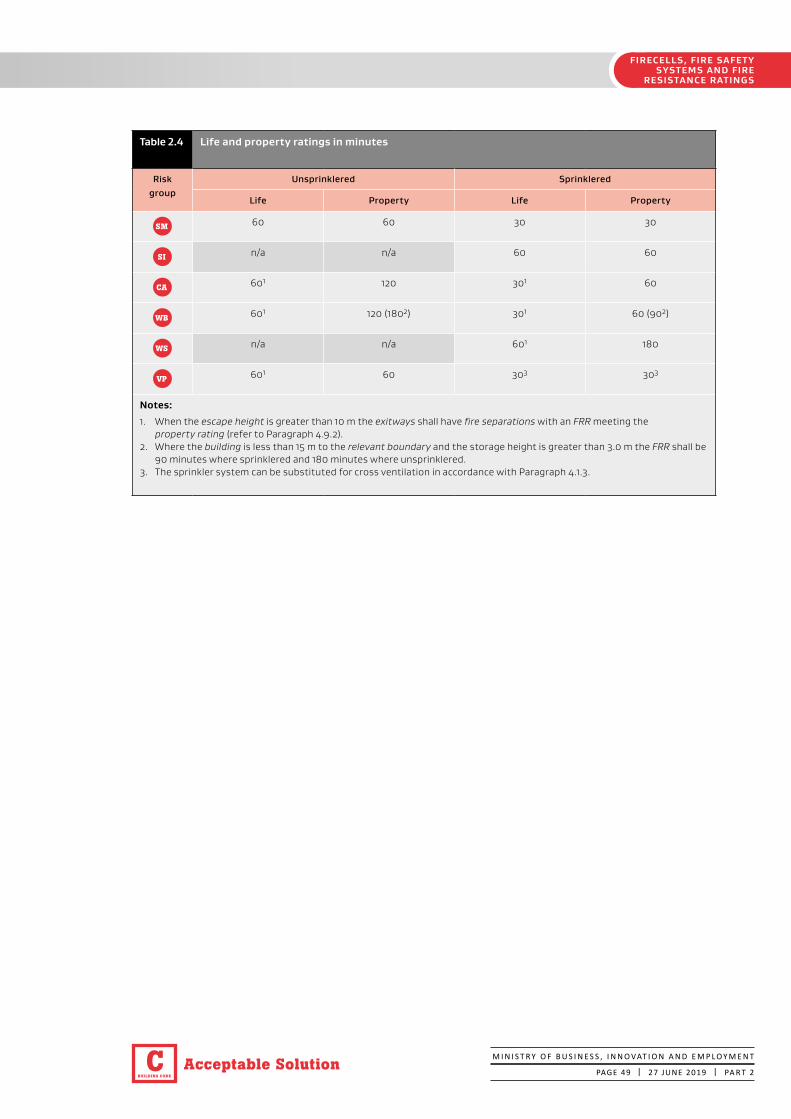
BUILDING CODE
C Acceptable Solution
FIRECELLS, FIRE SAFETY SYSTEMS AND FIRE
RESISTANCE RATINGS
M I N I S T R Y O F B U S I N E S S , I N N O VAT I O N A N D E M P L O Y M E N T
PAGE 49 | 27 JUNE 2019 | PA R T 2
Table 2.4 Life and property ratings in minutes
Risk group
Unsprinklered Sprinklered
Life Property Life Property
SM 60 60 30 30
SI n/a n/a 60 60
CA 601 120 301 60
WB 601 120 (1802) 301 60 (902)
WS n/a n/a 601 180
VP 601 60 303 303
Notes:
1. When the escape height is greater than 10 m the exitways shall have fire separations with an FRR meeting the property rating (refer to Paragraph 4.9.2).
2. Where the building is less than 15 m to the relevant boundary and the storage height is greater than 3.0 m the FRR shall be 90 minutes where sprinklered and 180 minutes where unsprinklered.
3. The sprinkler system can be substituted for cross ventilation in accordance with Paragraph 4.1.3.

BUILDING CODE
CAcceptable Solution
MEANS OF ESCAPE
M I N I S T R Y O F B U S I N E S S , I N N O VAT I O N A N D E M P L O Y M E N T
PAGE 50 | 5 NOVEMBER 2020 | PA R T 3
Part 3: Means of escape
CONTENTS
3.1 General principles
3.2 Number of escape routes
3.3 Height and width of escape routes
3.4 Length of escape routes
3.5 Escape from basements
3.6 Open paths
3.7 Special cases of open paths
3.8 Dead ends
3.9 Exitways
3.10 Control of exitway activities
3.11 External escape routes
3.12 Final exits
3.13 Single escape routes
3.14 Special conditions
3.15 Doors subdividing escape routes
3.16 Signs
3.1 General principles
3.1.1 All buildings shall have means of escape from fire which include escape routes. An escape route (see Figure 3.1) shall provide protection to any occupant escaping to a safe place from a fire within a building.
3.1.2 The components of an escape route, in ascending order of protection, are the:
a) Open paths, and
b) Exitways (these may comprise of smoke lobbies and safe paths), and
c) Final exits (see Figure 3.1).
Two or more of these components will be necessary, depending on the total travel distance.
An escape route shall not pass from a higher to lower level of protection in the direction of escape.
3.1.3 Provided the allowable lengths of open paths are not exceeded, an escape route may comprise only an open path and final exit.
3.1.4 Escape routes shall comply with NZBC Clause D1. Ramps, stairs, ladders, landings, handrails, doors, vision panels and openings shall comply with Acceptable Solution D1/AS1.
3.2 Number of escape routes
3.2.1 Except where Paragraph 3.13 allows the use of single escape routes, every occupied space in a building shall be served by two or more escape routes (see Figure 3.2).
3.2.2 The minimum number of escape routes from a floor level, except in those situations where single escape routes are permitted (see Paragraph 3.13), shall be in accordance with Table 3.1.
Amend 2Nov 2020

BUILDING CODE
C Acceptable Solution
MEANS OF ESCAPE
M I N I S T R Y O F B U S I N E S S , I N N O VAT I O N A N D E M P L O Y M E N T
PAGE 51 | 27 JUNE 2019 | PA R T 3
Figure 3.1 Escape routesParagraphs 3.1.1 and 3.1.2
Note:The final exit is where the escape route enters a safe place. This might be beyond the exit door from the building.

BUILDING CODE
CAcceptable Solution
MEANS OF ESCAPE
M I N I S T R Y O F B U S I N E S S , I N N O VAT I O N A N D E M P L O Y M E N T
PAGE 52 | 27 JUNE 2019 | PA R T 3
Table 3.1 Minimum number of escape routes from a floor level or firecell
Risk group
Number of occupants
≤50 51-100 101-150 151-200
201-250
251-300
301-500
501-1000
1001-2000
2001-4000
4001-7000
SM 1* 2 3 3 4 4
SI 2 3 3 4 4
CA 1* 2 2 2 2 2 2 3 4 5 6
WB 1* 2 2 2 2 2 2 3 4 5 6
WS 1* 2 2 2 2 2 2 3 4 5
VP 1* 2 2 2 2 2 2 3 4 5 6
Note:
* Refer to Paragraphs 3.13.1 to 3.13.6 for limitations.
Table 3.1a
Minimum clear width of escape routes, excluding ladders (mm) Paragraphs 3.3.2 and 3.15.5
Risk group
ElementOpen path1 Exitway
Horizontal Vertical Horizontal Vertical
SM Escape Route
850 1000 1000 1000
Door 760 760 875 875
SI Escape Route
8502 1000 1200 1500
Door 7602 760 950 1200
CA
WB
WS
VP
Escape Route
850 1000 1000 1000
Door 760 760 875 875
Notes:
1. Escape route widths may be reduced for single escape routes as permitted by Paragraph 3.3.2c) ii).2. Additional minimum clear widths are provided in Paragraph 3.15.5 a) and f) where the movement of beds is required.

BUILDING CODE
C Acceptable Solution
MEANS OF ESCAPE
M I N I S T R Y O F B U S I N E S S , I N N O VAT I O N A N D E M P L O Y M E N T
PAGE 53 | 27 JUNE 2019 | PA R T 3
SI
SI
3.3 Height and width of escape routes
Height
3.3.1 Height requirements within escape routes shall be as follows:
a) The clear height shall be no less than that required by D1/AS1, and
b) Any door opening within, or giving access to, any escape route shall have a clear height of no less than 1955 mm for the required width of the opening.
Width
3.3.2 Escape route widths shall be in accordance with Table 3.1a and the following requirements:
a) Width of all available escape routes: the total combined width of all available escape routes shall allow 7 mm/person for horizontal travel and 9 mm/person for vertical travel.
Figure 3.2 Minimum number of escape routesParagraph 3.2.1
Safe path
Safe path
To final exit
To final exit
To final exit
To final exit
Unless exempted by Paragraph 3.13no building shall have fewer than two escape routes.
For risk group SI the total combined width of all available escape routes shall allow 8 mm/person for horizontal travel and 10 mm/person for vertical travel.
b) Width of individual escape routes for risk group SI: these shall be no less than 1200 mm for horizontal travel, and 1500 mm for vertical travel. See Paragraph 3.15.5 for widths of doors required for the passage of beds.
c) Width of individual escape routes: these shall have a minimum width of 850 mm for horizontal travel and 1000 mm for vertical travel, except in the following cases:
i) if an escape route is within an exitway, its width shall be no less than 1000 mm, and
ii) if an escape route is within an open path and a single escape route is permitted, its width may be reduced to 700 mm for horizontal travel and 850 mm for vertical travel.

BUILDING CODE
CAcceptable Solution
MEANS OF ESCAPE
M I N I S T R Y O F B U S I N E S S , I N N O VAT I O N A N D E M P L O Y M E N T
PAGE 54 | 27 JUNE 2019 | PA R T 3
d) Provision for unusable escape routes: except where dead ends and single escape routes are permitted, in unsprinklered firecells the total required width shall still be available should the widest of the escape routes be unusable due to the location of the fire or any other reason (see Figure 3.3).
e) Sprinkler concession: if the firecell is sprinklered, requirement d) does not apply (i.e. it is not necessary to provide extra width to allow for the possibility that one escape route may be unusable).
f) Horizontal escape route with a single direction of escape: this shall be wide enough at any point to take the full occupant load from all contributing occupied spaces. However, the escape route may have its width increased progressively as it passes the exit from each occupied space (see Figure 3.4).
g) Horizontal escape route with two directions of escape: this shall have sufficient width for the full length of the route to allow for the occupant load from all contributing occupied spaces. However, this shall not apply if the requirements of Paragraph 3.7.14 e) are met for escape through adjacent firecells.
h) Intermediate floors: for firecells containing an intermediate floor, both the vertical and horizontal parts of the open path escape route shall be wide enough to take the full occupant load from all contributing occupied spaces.
CASM
CA
i) Vertical safe path widths: Vertical safe paths shall have minimum widths at any point determined only by the largest total occupant load passing that point in the direction of escape from:
i) any single level (where not part of an intermediate floor firecell)
ii) all levels in a firecell where it spans more than one level.
j) Marae buildings using traditional Māori construction materials in risk groups SM and CA: where applying the exception permitted in Paragraph 4.17.6 i), the escape route widths required by Paragraph 3.3.2 shall be doubled.
k) Basements: if an escape route from upper floors is joined at the level of a final exit by an escape route from a basement or lower floors, the escape route width at the point they combine shall be increased to accommodate the occupant loads from both directions (see Figure 3.5).
l) Ladders: the width requirements of Paragraph 3.3.2 c) do not apply to ladders where their use is permitted in this Acceptable Solution.
m) Fixed or loose seating in risk group CA: the width requirements of Paragraph 3.3.2 a) to e) do not apply to fixed or loose seating.

BUILDING CODE
C Acceptable Solution
MEANS OF ESCAPE
M I N I S T R Y O F B U S I N E S S , I N N O VAT I O N A N D E M P L O Y M E N T
PAGE 55 | 27 JUNE 2019 | PA R T 3
Figure 3.3 Exitway widths in unsprinklered firecellsParagraph 3.3.2 d)
The combined width of the two narrowest exitways shall be sufficient to take the full occupant load.
A + B=C
Escape route
Escape route widthincreases as it passeseach contributing doorway
Exit doors
Exitways A and B each wide enough totake the full occupant load.
The combined width of any two exitways shallbe sufficent to take the full occupant load.
Exitway A Exitway B Exitway A Exitway B
Exitway C
1 J u n e 2 0 0 1 D E P A R T M E N T O F B U I L D I N G A N D H O U S I N G50
P A R T 3 : M E A N S O F E S C A P E Acceptable Solut ion C/AS1
Figure 3.3: Exitway Widths in Unsprinklered FirecellsParagraph 3.3.2 b)
Figure 3.4: Increase in Width for Horizontal Escape Routes Having a Single Direction of EscapeParagraph 3.3.2 d)
VUB 5640 C pt 3 1.5_ƒa 14/11/08 2:25 PM Page 50
Figure 3.4 Increase in width for horizonatal escape routes having a single direction of escapeParagraph 3.3.2 f)

BUILDING CODE
CAcceptable Solution
MEANS OF ESCAPE
M I N I S T R Y O F B U S I N E S S , I N N O VAT I O N A N D E M P L O Y M E N T
PAGE 56 | 27 JUNE 2019 | PA R T 3
Figure 3.5 Escape routes from lower and upper floorsParagraph 3.3.2 k)

BUILDING CODE
C Acceptable Solution
MEANS OF ESCAPE
M I N I S T R Y O F B U S I N E S S , I N N O VAT I O N A N D E M P L O Y M E N T
PAGE 57 | 5 NOVEMBER 2020 | PA R T 3
Handrails and limitations to stairway widths
3.3.3 For safe evacuation on stairs, all stairways shall have at least one handrail. Furthermore:
a) Stairways in escape routes wider than 1500 mm shall have handrails on both sides, and
b) Stairways in escape routes wider than 2000 mm (see Figure 3.6) shall also be provided with intermediate handrails which are equally spaced and which provide a width not greater than 1500 mm for each section of the stairway.
3.3.4 If the escape height exceeds 35 m, no more than 1500 mm shall be credited to the width of any stairway when calculating stairway capacity for an escape route.
Curved and spiral stairs
3.3.5 Where curved or spiral stairs form part of an escape route, the required width of such stairs is to be measured across the tread where the tread depth meets the requirements for the tread depth in Acceptable Solution D1/AS1.
Obstructions
3.3.6
The following minor obstructions are acceptable within the width of an escape route:
a) Minor projections complying with the requirements of Acceptable Solution D1/AS1 such as signs, switches, alarm sounders and similar projections, and
b) Handrails complying with Acceptable Solution D1/AS1 and projecting no more than 100 mm into the width, and handrails subdividing wide stairways that reduce the width by no more than 100 mm (see Paragraph 3.3.3), and
c) Door assemblies which reduce the width of an exitway by no more than 125 mm when the door is fully open (see Figure 3.23), or as permitted by Table 3.1a, and
d) In risk group CA fixed seating (at the start of an escape route) which complies with the requirements of Paragraph 3.7.4 and Table 3.3 for the width of aisles and space between rows.
3.3.7 Except as permitted by Paragraph 3.15.7, escape routes shall not be obstructed by access control systems.
CA
Amend 2Nov 2020
Amend 2Nov 2020
Amend 2Nov 2020

BUILDING CODE
CAcceptable Solution
MEANS OF ESCAPE
M I N I S T R Y O F B U S I N E S S , I N N O VAT I O N A N D E M P L O Y M E N T
PAGE 58 | 5 NOVEMBER 2020 | PA R T 3
Figure 3.6 Limitations to stairway widthsParagraph 3.3.3 b)
3.4 Length of escape routes
3.4.1 An escape route may be any length, but:
a) The lengths of dead ends and total open paths shall not exceed the distances given in Table 3.2, adjusted as necessary for:
i) reductions on intermediate floors (see Paragraph 3.4.3), apart from risk group VP firecells with adequate cross ventilation in accordance with Paragraph 4.1.3, and
ii) reductions on stairs and ladders (see Paragraph 3.4.4), and
b) If the distance to the final exit exceeds the allowable length for total open paths, the remainder of the escape route shall be a safe path (see Paragraph 3.9.7 for safe path length restrictions within a single floor level).
Open paths
3.4.2 When determining open path lengths, including any dead end, the following shall apply:
a) Start point: the length shall be measured from no more than 1.0 m from the most remote point in a space.
b) Multiple risk groups: the lengths specified in Table 3.2 shall apply to all risk groups. When other risk groups with different allowable maximum open paths lengths use the same open path, the open path length for the risk group with the shortest maximum length shall apply.
c) Furniture and fittings: allowance shall be made for the travel distance around obstructions such as furniture, fittings and office equipment located in the open path (see Figure 3.7(a)). If the location of such obstructions is not known, then the allowable travel distance shall be measured orthogonally (see Figure 3.7(b)).
Amend 2Nov 2020

BUILDING CODE
C Acceptable Solution
MEANS OF ESCAPE
M I N I S T R Y O F B U S I N E S S , I N N O VAT I O N A N D E M P L O Y M E N T
PAGE 59 | 27 JUNE 2019 | PA R T 3
d) Multiple escape routes: if two or more escape routes are required, open path lengths from any point on a floor to no fewer than two exits from the firecell shall not exceed the lengths specified in Table 3.2.
e) Marae buildings using traditional Māori construction materials: when applying the exception permitted in Paragraph 4.17.6 (i), the permitted length of the open path specified in Table 3.2 shall be halved.
f) Termination: an open path ends either at:
i) the start of an exitway, or
ii) a final exit, or
iii) the point where the escape route passes into an adjacent firecell on the same level (see Paragraph 3.7.13).
Intermediate floors
3.4.3 On intermediate floors (see Figure 3.8), the open path length shall be taken as 1.5 times the measured length in accordance with Paragraph 3.4.2 c). However, the measured length may be used where the intermediate floor is a smokecell and an escape route is available from the intermediate floor without passing through any lower space in the same firecell.
Stairs and ladders
3.4.4 Stairs and ladders occurring in an open path (see Figure 3.9) shall have their open path length taken as:
a) For straight and curved stairs: the plan length measured on the stair centreline multiplied by 1.2, plus the plan length of each landing,
b) For spiral stairs: twice the vertical height, and
c) For ladders: three times the vertical height.
Sloping floors and ceilings
3.4.5 The open path length permitted by Table 3.2 shall be reduced by 50% in any space where the following conditions apply:
a) Both the floor and the ceiling slope in the same direction at an angle of more than 4° from the horizontal, and any escape route from the space is up the slope, and
b) The clear ceiling height at any point is less than 4.0 m, and
c) The occupant load in the space is more than 50, and
d) The space is unsprinklered.
Escape through adjoining building
3.4.6 An escape route may be via an adjoining building (see Figure 3.10), provided the following conditions are satisfied:
a) The escape route through the adjoining building meets all escape route requirements for the occupant load from the fire affected building requiring to use that route, and
b) Unless the escape route passes directly to a safe path in the adjoining building, access shall be through a smoke lobby before passing through the external walls, and
c) The opening through the external wall having the higher FRR has a fire door with an FRR of no less than that wall, and
d) Escape routes in the adjoining building comply with the Building Code and have sufficient capacity to carry the occupant load from the building or buildings being evacuated, and
e) The escape route does not re-enter the first building at any point, and is freely available at all times.

BUILDING CODE
CAcceptable Solution
MEANS OF ESCAPE
M I N I S T R Y O F B U S I N E S S , I N N O VAT I O N A N D E M P L O Y M E N T
PAGE 60 | 27 JUNE 2019 | PA R T 3
Table 3.2 Travel distances on open paths (metres)Paragraph 3.4
Risk group
No system and Type 2 system
Type 3 system Type 4 and Type 5* systems
Type 6 system Type 7 system
Dead end
open path
Total open path
Dead end
open path
Total open path
Dead end
open path
Total open path
Dead end
open path
Total open path
Dead end
open path
Total open path
SM 20 50 30 75 30 75 40 100
SI 20 50
CA 20 50 20 50 40 100 40 100 50 120
WB 25 60 35 75 50 120 50 120 75 150
WS 50 120 75 180
VP 35 90 45 110 70 180
Notes:
If open path length increases for a Type 4 system are being applied, where Acceptable Solution F7/AS1 allows heat detectors to be substituted for smoke detectors, not less than 70% of the firecell shall be protected with smoke detectors.
If smoke and heat detection systems are installed in order to extend permissible travel distance in accordance with this table and are not a requirement of Paragraph 2.2.1 then Fire and Emergency New Zealand connection is not required.
* Type 5 system only for risk group SM.

BUILDING CODE
C Acceptable Solution
MEANS OF ESCAPE
M I N I S T R Y O F B U S I N E S S , I N N O VAT I O N A N D E M P L O Y M E N T
PAGE 61 | 27 JUNE 2019 | PA R T 3
Figure 3.7 Length of open pathsParagraph 3.4.2
Final Exit
Starting Point
Starting Point
Each person shall have at least two escape routes available unless exempted by Paragraph 3.13
Open path lengths includetravel around furnitureand fittings.Open path not to exceedlength in Table 3.2
Open path length = A + BOpen path not to exceedlength in Table 3.2
1 m
1 m
Ending Point
Final Exit
Ending Point

BUILDING CODE
CAcceptable Solution
MEANS OF ESCAPE
M I N I S T R Y O F B U S I N E S S , I N N O VAT I O N A N D E M P L O Y M E N T
PAGE 62 | 27 JUNE 2019 | PA R T 3
Figure 3.8 Intermediate floor open path lengthParagraph 3.4.3

BUILDING CODE
C Acceptable Solution
MEANS OF ESCAPE
M I N I S T R Y O F B U S I N E S S , I N N O VAT I O N A N D E M P L O Y M E N T
PAGE 63 | 27 JUNE 2019 | PA R T 3
Figure 3.9 Stairs and laddersParagraph 3.4.4

BUILDING CODE
CAcceptable Solution
MEANS OF ESCAPE
M I N I S T R Y O F B U S I N E S S , I N N O VAT I O N A N D E M P L O Y M E N T
PAGE 64 | 5 NOVEMBER 2020 | PA R T 3
Figure 3.10 Escape through adjoining buildingParagraphs 3.4.6 and 4.15.8 c)Figure 3.10 Escape through adjoining building
Paragraphs 3.4.6 and 4.6.9
Fire separation and fire door between buildings A and B
Smoke lobby in building A
Exitway for two upper floors of building A
Exitway for one upper floor of building A
Exitway in building B
Exitway in building B
Amend 2Nov 2020
Amend 2Nov 2020

BUILDING CODE
C Acceptable Solution
MEANS OF ESCAPE
M I N I S T R Y O F B U S I N E S S , I N N O VAT I O N A N D E M P L O Y M E N T
PAGE 65 | 5 NOVEMBER 2020 | PA R T 3
Figure 3.11 Single escape from basement levelsParagraphs 3.5.1 and 3.13.1 d)
NOTES:1. Occupant load at each basement level no greater than 502. A single escape route is permitted only when there are no more than two basement levels
Smoke lobby preceding safe path from basement levels
Amend 2Nov 2020
Amend 2Nov 2020

BUILDING CODE
CAcceptable Solution
MEANS OF ESCAPE
M I N I S T R Y O F B U S I N E S S , I N N O VAT I O N A N D E M P L O Y M E N T
PAGE 66 | 27 JUNE 2019 | PA R T 3
3.5 Escape from basements
3.5.1 Except in cases where there are two or more escape routes serving only the basement firecells and each terminates in a safe place, safe paths serving basement firecells shall be preceded by a smoke lobby that shall have a plan area in accordance with Paragraph 3.9.2 (see Figure 3.11).
3.6 Open paths
Number and size
3.6.1 Open paths shall satisfy the specific requirements of Paragraphs 3.6.2, 3.6.3 and 3.7 where they apply to a particular building.
Open path separation
3.6.2 If two or more open paths are required, they shall be separated from each other, and remain separated until reaching an exitway or final exit (see Figure 3.12). Separation shall be achieved by diverging (from the point where two escape routes are required), at an angle of no less than 90° until separated by:
a) A distance of at least 8.0 m, or
b) Smoke separations and smoke control doors.
Figure 3.12 Alternative open path separation Paragraph 3.6.2

BUILDING CODE
C Acceptable Solution
MEANS OF ESCAPE
M I N I S T R Y O F B U S I N E S S , I N N O VAT I O N A N D E M P L O Y M E N T
PAGE 67 | 5 NOVEMBER 2020 | PA R T 3
Exception for education buildings
3.6.3 If a building houses classrooms, laboratories and/or spaces used for home economics, art and crafts, workshops or similar teaching activities, one open path may be via a connecting corridor and the alternative open path may be via connecting doors between adjacent teaching spaces. In such cases, the separation requirements of Paragraph 3.6.2 need not apply provided that:
a) The number of occupants in each teaching space does not exceed 100, and
b) The escape route does not pass through a space which may be locked.
3.7 Special cases of open paths
Passing into an adjacent firecell
3.7.1 If an escape route passes through a number of fire separations it is permitted to continue as an open path provided the cumulative travel distance does not exceed the permitted distance specified in Table 3.2.
3.7.2 An open path may pass into an adjacent firecell on the same level (see Figure 3.15) and recommence as a new open path provided that:
a) All firecells on the escape route have no fewer than two directions of escape, separated as required by Paragraph 3.6.2, and
Table 3.3 Walkways in fixed seatingParagraph 3.7.6
Minimum walkway
width (mm)
Maximum number of seats in any row
One aisle Aisles both sides
300 7 14
340 9 16
380 9 18
420 10 20
460 11 22
500 12 24
b) Adjacent firecells into which evacuation may take place have an available floor area to accommodate not only their own occupants, but also the occupants from the adjacent firecell. This shall be calculated on the basis of the occupant load of the two firecells with not less than 1.0 m2 of space provided for each occupant. Refer to Paragraph 4.6.2 for additional requirements for risk group SI, and
c) Each firecell has at least one other escape route independent of the route into the adjacent firecell. This other route may be by way of a final exit or via a third firecell provided that the exit from that third firecell is independent of exits from the other two firecells, and
d) The escape route does not pass through more than three fire separations before entering an exitway or final exit, and
e) The escape route width meets the requirements of Paragraph 3.3.2 for the firecell on the escape route that has the greatest occupant load.
Separate tenancy
3.7.3 Open paths shall only pass through spaces containing different tenancies if doors leading to an exitway or final exit can be readily opened by all persons for whom the open path is their escape route
CAAmend 2Nov 2020
Amend 2Nov 2020
Amend 2Nov 2020
Amend 2Nov 2020
Amend 2Nov 2020

BUILDING CODE
CAcceptable Solution
MEANS OF ESCAPE
M I N I S T R Y O F B U S I N E S S , I N N O VAT I O N A N D E M P L O Y M E N T
PAGE 68 | 5 NOVEMBER 2020 | PA R T 3
Escape via an intermediate floor
3.7.4 For all risk groups excluding SI, an open path may pass from a firecell on to an intermediate floor and recommence as an open path provided that:
a) Where two or more escape routes are required from that firecell, only one escape route shall be via the intermediate floor, and
b) The intermediate floor open path length shall not exceed the requirements of Paragraph 3.4.3, and
c) The intermediate floor is served by at least two escape routes, separated as required by Paragraph 3.6.2, and terminating at any of the following: i) separate firecells, ii) separate exitways, or iii) final exits.
Open paths via unenclosed stairs
3.7.5 In risk group SM, unenclosed stairs (stairs which are not smoke separated or fire separated from other spaces) in escape routes, other than those within a household unit or suite, shall not exceed a height of 4.0 m within the firecell. Where the height exceeds 4.0 m, the escape route from that level shall be a safe path until it reaches a final exit.
Fixed seating
3.7.6 Fixed seating (except for within household units or suites) which includes seating that is moveable or foldaway, shall be arranged so that:
a) Direct access to the aisles is available, and
b) The number of seats in a row is no greater than that specified in Table 3.3, and
c) The clear walkway width between rows is no less than that specified in Table 3.3, and
d) The area occupied by each seat plus the walkway in front of it has a total dimension of at least 760 mm from seat back to seat back measured horizontally at right angles to the rows of seats (see Figure 3.13). The seat width must be at least:
i) 500 mm where arms are provided (see Figure 3.13), and
ii) 450 mm where arms are not provided.
Loose seating
3.7.7 Except for within household units or suites, loose seating is permitted only on level floors. The layout shall follow the requirements of Paragraphs 3.7.9 to 3.7.14.
3.7.8 Where the number of seats exceed 250, loose seating shall be interconnected to prevent overturning.
Aisles
3.7.9 Except within household units or suites, aisles serving fixed or loose seating (see Figure 3.14) shall provide access to final exits or escape routes. The width of the final exits or escape routes shall be the greater of the:
a) Aisle width as required by Paragraph 3.7.10, or
b) Width required by Paragraph 3.3.2.
3.7.10 Aisle widths shall be no less than:
a) 750 mm when serving up to 60 seats,
b) 900 mm when serving over 60 seats on one side only, or
c) 1100 mm in all other cases.
The minimum width shall occur at:
d) If discharge is in one direction only, the point furthest from the exit door in aisles, or
e) If discharge is in two directions, the mid-length of an aisle to separate cross-aisles or to separate exit doors.
There is nothing to prevent an aisle being made wider than the minimum required. However, to avoid restrictions, this shall be done only in the direction of travel.
3.7.11 Each cross-aisle shall have a width of no less than that of the widest aisle it serves plus 50% of the sum of the widths of all other aisles served.
3.7.12 The travel distance from any seat to an adjacent firecell, a final exit, or exitway shall be no greater than allowed for an open path in Table 3.2. If there are sloping ceilings and floors, refer to Paragraph 3.4.5 for further restrictions.
SI
SM
Amend 2Nov 2020
Amend 2Nov 2020
Amend 2Nov 2020
Amend 2Nov 2020
Amend 2Nov 2020
Amend 2Nov 2020
Amend 2Nov 2020
Amend 2Nov 2020
Amend 2Nov 2020
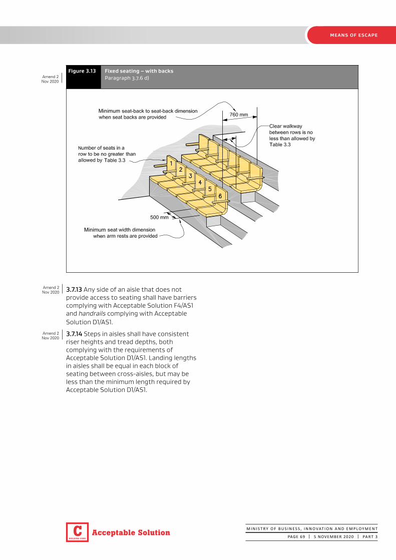
BUILDING CODE
C Acceptable Solution
MEANS OF ESCAPE
M I N I S T R Y O F B U S I N E S S , I N N O VAT I O N A N D E M P L O Y M E N T
PAGE 69 | 5 NOVEMBER 2020 | PA R T 3
Figure 3.13 Fixed seating – with backsParagraph 3.7.6 d)
3.7.13 Any side of an aisle that does not provide access to seating shall have barriers complying with Acceptable Solution F4/AS1 and handrails complying with Acceptable Solution D1/AS1.
3.7.14 Steps in aisles shall have consistent riser heights and tread depths, both complying with the requirements of Acceptable Solution D1/AS1. Landing lengths in aisles shall be equal in each block of seating between cross-aisles, but may be less than the minimum length required by Acceptable Solution D1/AS1.
Amend 2Nov 2020
Amend 2Nov 2020
Amend 2Nov 2020

BUILDING CODE
CAcceptable Solution
MEANS OF ESCAPE
M I N I S T R Y O F B U S I N E S S , I N N O VAT I O N A N D E M P L O Y M E N T
PAGE 70 | 5 NOVEMBER 2020 | PA R T 3
Minimum aisle width at mid-length of aisle, which discharges in two directions 750 mm for up to 60 seats 1100 mm for over 60 seats
Cross aisle access to escape route
Escape route
Escape route
Final exit
Figure 3.14 Aisles serving fixed seatingParagraph 3.7.9Amend 2
Nov 2020
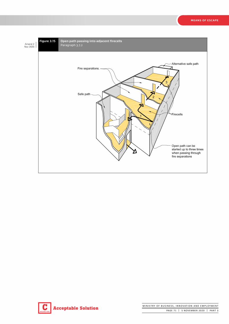
BUILDING CODE
C Acceptable Solution
MEANS OF ESCAPE
M I N I S T R Y O F B U S I N E S S , I N N O VAT I O N A N D E M P L O Y M E N T
PAGE 71 | 5 NOVEMBER 2020 | PA R T 3
Figure 3.15 Open path passing into adjacent firecellsParagraph 3.7.2 Amend 2
Nov 2020

BUILDING CODE
CAcceptable Solution
MEANS OF ESCAPE
M I N I S T R Y O F B U S I N E S S , I N N O VAT I O N A N D E M P L O Y M E N T
PAGE 72 | 5 NOVEMBER 2020 | PA R T 3
3.8 Dead ends
3.8.1 A dead end terminates where the escape route reaches a point in the open path which offers alternative directions of travel, or at a final exit or an exitway.
No more than 50 occupants
3.8.2 A dead end shall not serve an occupant load greater than 50.
Ladders
3.8.3 For all risk groups excluding SM and SI, the escape route from a dead end may be a ladder complying with Acceptable Solution D1/AS1 if it serves only support activities or provides the same function in support of other risk groups, and only if the occupant load does not normally exceed four.
Ladders are not permitted as escape routes in any other circumstances (see also Paragraph 3.4.4).
3.9 Exitways
3.9.1 Exitways consist of either: smoke lobbies, or safe paths, or both.
Smoke lobbies – floor area
3.9.2 If a smoke lobby is required preceding a vertical safe path (see Paragraphs 3.5.1, 3.9.3 and 3.13.1 and Figures 3.11 and 3.16), its floor area shall be calculated for the occupant load using that smoke lobby and its size shall be at least that required by the doors and opening requirements of D1/AS1, on the basis that:
a) Part of the occupant load will be accommodated in the vertical safe path between the level being considered and the next level in the direction of escape, with the remaining occupants accommodated in the smoke lobby, and
Figure 3.16 Sizing of smoke lobbiesParagraph 3.9.2
The size shall be at least that required by D1/AS1
SM SI
Amend 2Nov 2020
Amend 2Nov 2020
Amend 2Nov 2020
Amend 2Nov 2020

BUILDING CODE
C Acceptable Solution
MEANS OF ESCAPE
M I N I S T R Y O F B U S I N E S S , I N N O VAT I O N A N D E M P L O Y M E N T
PAGE 73 | 5 NOVEMBER 2020 | PA R T 3
b) The occupant density for calculating the required holding area shall be 0.25 m2
per person. The usable floor area within the stairwell shall be taken as the area of the first landing, plus the plan area of the flights of stairs between the two floor levels, plus the areas of any intermediate landings. Additional space shall be provided for door swings.
Smoke lobbies – exitways from upper and intermediate floors
3.9.3 For risk groups SM and CA, entrances to vertical safe paths shall be preceded by smoke lobbies (refer to Paragraph 3.9.2 for the required area of the smoke lobby) except where:
a) The safe path from an upper floor or intermediate floor serves only that floor, or
b) The firecell is sprinklered, or
c) The occupant load of the firecell is less than 150, or
d) The vertical safe path is preceded by a horizontal safe path.
Safe paths
3.9.4 Escape routes from firecells shall enter directly into a safe path or final exit, except where Paragraphs 3.7.13 and 3.7.14 permit open paths to continue from one firecell to another.
3.9.5 Safe paths shall be separated from each other, and from all spaces by:
a) Fire separations, or
b) If they are external to the building, by distance or appropriate construction (see Paragraph 3.11).
3.9.6 Except where the conditions for escape via an external escape route (see Paragraph 3.11) or successive open paths (see Paragraphs 3.7.1 and 3.7.2) apply, exit doors from sleeping area firecells shall open directly onto:
a) A horizontal safe path, or
b) A final exit.
Safe path length restrictions
3.9.7 There is no limit on the length of a vertical safe path. Horizontal safe paths shall be no longer than specified in Table 3.4.
Safe path termination
3.9.8 Horizontal safe paths shall terminate at any of the following:
a) The entrance to an internal stairway which is a separate safe path, or
b) An external balcony leading to either an open or enclosed stairway, or
c) An opening in an external wall which enters on to a bridge leading to an open or enclosed stairway, or
d) A final exit.
Safe path separation, glazing and smoke separation
3.9.9 Fire doors with smoke control capability shall be provided where open paths and horizontal safe paths provide access to internal vertical safe paths.
3.9.10 Glazing in safe paths shall comply with the requirements of Paragraph 4.2.
3.9.11 For risk group SI only, at least half the safe paths shall terminate in a safe place without being combined with an escape route from any other risk group.
CASM
SM
SI
SI
Amend 2Nov 2020

BUILDING CODE
CAcceptable Solution
MEANS OF ESCAPE
M I N I S T R Y O F B U S I N E S S , I N N O VAT I O N A N D E M P L O Y M E N T
PAGE 74 | 5 NOVEMBER 2020 | PA R T 3
3.10 Control of exitway activities
3.10.1 Exitways shall not be used for:
a) Any storage of goods, solid waste or solid waste containers, or
b) Entry points to solid waste chutes, or
c) The location of furniture or other combustibles, or
d) Storage of cloaks or linen, or
e) A cleaner’s cupboard not fire separated from the exitway, or
f) The location of an electrical switchboard or similar, or
g) Any activity (other than as permitted by Paragraph 3.10.2).
3.10.2 Some activities are permitted in an exitway if:
a) An alternative escape route is available from all firecells served by the safe path in which the activities occur, and
b) For buildings:
i) with an occupant load of not more than 500, where a Type 4 or 5 system is installed, or
ii) with an occupant load of more than 500 where a Type 7 system is installed, and
c) The escape route is not impeded by the activity or the occupants involved in that activity, and
d) Those activities:
i) are visible to users of the exitway, except in the case of sanitary fixtures, and
ii) are a direct support function of the risk group served by the exitway, and
iii) occupy a total floor area of not more than 6.0 m2 except in the case of sanitary fixtures.
Lifts
3.10.3 A passenger lift, but not a goods lift, may be located in a vertical safe path containing a stairway provided the following conditions are satisfied:
a) The lift shaft and all its openings are located entirely within a single firecell containing the vertical safe path, and
b) Passenger access into and from the lift car takes place entirely within the safe path, and
c) No other activity occurs within the vertical safe path, and
d) The lift is provided with a machine room that is a separate firecell, and the openings for lift ropes through the fire separation are as small as practicable, and any penetrations, such as for electrical cables, are fire stopped (refer to Paragraph 4.4 for fire stopping).
3.10.4 Lift landings shall not open into or be located between open paths (see Figures 3.17 and 3.18) and shall either be provided with a smoke lobby separated from all other areas or have lift landing doors with smoke control capability. This requirement does not apply if the building is protected with a Type 7 system or the lift shaft has a pressurisation system designed to AS/NZS 1668.1. The lift doors shall be as specified in Paragraphs 4.16.3 and 4.16.11.
3.10.5 In situations not described in Paragraphs 3.10.3 or 3.10.4, lift landings in unsprinklered buildings shall either open into a smoke lobby or the lift shaft shall be provided with a pressurisation system designed to AS/NZS 1668.1. Any smoke lobby shall not be part of the horizontal safe path (i.e. the horizontal safe path shall not pass through the smoke lobby). See Figure 3.18. The lift doors shall be as specified in Paragraphs 4.16.3 and 4.16.11.
Amend 2Nov 2020
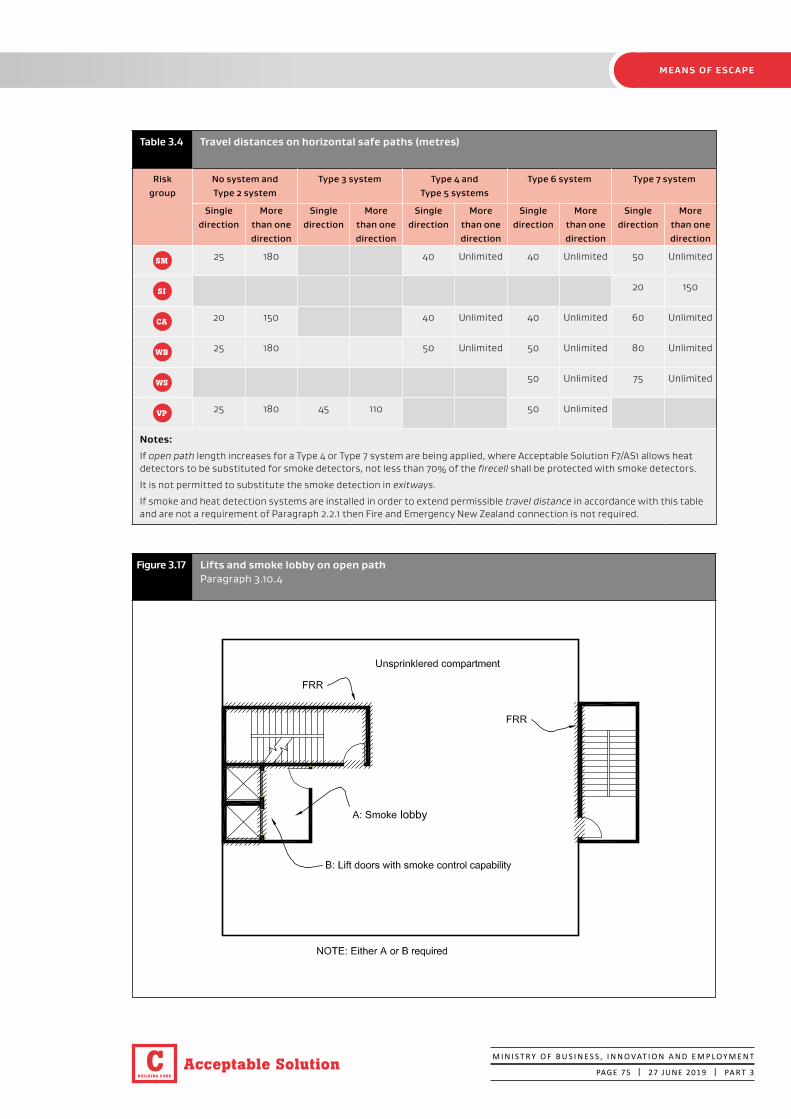
BUILDING CODE
C Acceptable Solution
MEANS OF ESCAPE
M I N I S T R Y O F B U S I N E S S , I N N O VAT I O N A N D E M P L O Y M E N T
PAGE 75 | 27 JUNE 2019 | PA R T 3
Figure 3.17 Lifts and smoke lobby on open pathParagraph 3.10.4
lobby
Table 3.4 Travel distances on horizontal safe paths (metres)
Risk group
No system and Type 2 system
Type 3 system Type 4 and Type 5 systems
Type 6 system Type 7 system
Single direction
More than one direction
Single direction
More than one direction
Single direction
More than one direction
Single direction
More than one direction
Single direction
More than one direction
SM 25 180 40 Unlimited 40 Unlimited 50 Unlimited
SI 20 150
CA 20 150 40 Unlimited 40 Unlimited 60 Unlimited
WB 25 180 50 Unlimited 50 Unlimited 80 Unlimited
WS 50 Unlimited 75 Unlimited
VP 25 180 45 110 50 Unlimited
Notes:
If open path length increases for a Type 4 or Type 7 system are being applied, where Acceptable Solution F7/AS1 allows heat detectors to be substituted for smoke detectors, not less than 70% of the firecell shall be protected with smoke detectors.
It is not permitted to substitute the smoke detection in exitways.
If smoke and heat detection systems are installed in order to extend permissible travel distance in accordance with this table and are not a requirement of Paragraph 2.2.1 then Fire and Emergency New Zealand connection is not required.

BUILDING CODE
CAcceptable Solution
MEANS OF ESCAPE
M I N I S T R Y O F B U S I N E S S , I N N O VAT I O N A N D E M P L O Y M E N T
PAGE 76 | 5 NOVEMBER 2020 | PA R T 3
3.11 External escape routes
3.11.1 If an escape route enters a space exposed to the open air (e.g. an open stairway, a balcony, across a roof or a ground level path), it shall meet the requirements of a safe path between that point and the final exit. Safe path separation requirements shall be achieved by providing either distance or fire rated construction between the escape route and adjacent firecells, as specified in Paragraphs 3.11.2 to 3.11.5.
Separation by distance
3.11.2 Separation by distance shall be achieved as follows:
a) If there is only one direction of escape, roofs and external walls shall not have unprotected areas closer to an external escape route than:
i) 2.0 m if unsprinklered (see Figure 3.19), or
ii) 1.0 m if all firecells passed by the external escape route are sprinklered, or
b) The escape route shall be located so that it diverges from external walls (see Paragraph 3.11.3), or
c) Where alternative directions of escape are provided from the point where the escape route passes through an external wall and becomes an external escape route (refer to Paragraph 3.11.3 b)), unprotected areas are permitted.
Figure 3.18 Lifts and smoke separations when landing on an unsprinklered horizontal safe pathParagraph 3.10.5
Lifts
occupants on horizontal safe path shall not need to egress through smoke lobby
either smoke separation to be provided or lift pressurisation systemlift smoke lobby to be separate from escape route
Stair
Stair
HSP = Horizontal safe path
������
Amend 2Nov 2020
Amend 2Nov 2020
Amend 2Nov 2020
Amend 2Nov 2020

BUILDING CODE
C Acceptable Solution
MEANS OF ESCAPE
M I N I S T R Y O F B U S I N E S S , I N N O VAT I O N A N D E M P L O Y M E N T
PAGE 77 | 5 NOVEMBER 2020 | PA R T 3
Figure 3.19 Single external escape routes, unsprinklered buildingParagraph 3.11.2(a)
Separation by fire rated construction
3.11.4 Except where the separation distance requirements of Paragraphs 3.11.2 and 3.11.3 are achieved:
a) External walls and roofs adjacent to external escape routes shall comply with the FRR requirements of Paragraphs 5.3 and 5.7.3 to 5.7.5 and have no unprotected areas, except that glazing for safe paths complying with Paragraph 4.2 shall be permitted, and
b) If the escape route is a balcony with a single direction of escape, and the vertical distance between the underside of the balcony and the closest unprotected area in the external wall below is less than 5.0 m (see Figure 3.20), balcony barriers shall:
i) have no openings, and
ii) for risk group SI be protected with a material having a Group Number of 1, and
iii) for all other risk groups (SM, CA, WB, WS and VP) achieve a Group Number no greater than 2, and
3.11.3 For an escape route which passes through an opening in an external wall, parts of the external wall need not be fire rated if:
a) The direction of escape to a single final exit diverges from the external wall at an angle of no less than 45° in plan, or
b) The directions of escape to alternative final exits diverge from each other at an angle of no less than 90° in plan and the escape routes subsequently do not both pass the same firecell (other than the firecell from which they originated), or
c) Where household units and suites have full height glazing adjacent to a balcony which may be the only means of access and egress. The balcony shall provide the occupants with more than one escape route from the exit door, enabling them to escape without passing a unit containing a fire, or
d) For shopfronts, if the final exit is onto the footpath it is not required to be fire rated.
SI
SI
Amend 2Nov 2020
Amend 2Nov 2020
Amend 2Nov 2020

BUILDING CODE
CAcceptable Solution
MEANS OF ESCAPE
M I N I S T R Y O F B U S I N E S S , I N N O VAT I O N A N D E M P L O Y M E N T
PAGE 78 | 5 NOVEMBER 2020 | PA R T 3
CA
c) If the vertical separation between the underside of an external escape route and unprotected areas in the external wall below is less than 5.0 m:
i) the floor of an external escape route closer to an external wall than required by Paragraph 3.11.2 shall have an FRR of no less than required by Paragraph 2.3, and
ii) treads and risers of stairs on external escape routes shall either be constructed from a material which has a critical radiant flux of no less than 2.2 kW/m2 or shall be protected on the underside with a material having a Group Number of no greater than 2, and
d) If a single escape route comprises external horizontal and internal vertical safe paths, a smoke separation shall be provided between them.
Ventilation openings
3.11.5 The open area of a balcony or bridge shall be no less than 50% of the balcony floor area, and shall be evenly distributed along the open sides and any approach ramp (see Figure 3.21). Where an escape route on a balcony is served by an open stairway, similar ventilation shall be provided on the stairway. Open sides shall not be enclosed, except that a fixed open grille may be used if it provides the required free air space.
Open air auditoriums
3.11.6 For risk group CA open tiered seating decks shall:
a) Have the number of escape routes required by Table 3.2 for the occupant load, and
b) Comply with Paragraphs 3.7.4 to 3.7.12 for aisles and walkways between seats (Table 3.3 seat numbers are permitted to be doubled in this use), and
Where the vertical separation between the underside of the balcony and the closest unprotected area in the external wall below is less than 5.0 m, barriers shall have no openings and be protected by a material having a Group Number as required by Paragraph 3.11.5 b).
Escape height no greater than 16 m or 25 m if sprinkled
External walls adjacent to the safe path shall be fire separations, or where there are unprotected areas of external wall, the safe path shall be separated by distance (see Paragraph 3.11)
Firecells
Single safe path open balcony and external stairway
Ventilation requirements to
open stairway are the same as for balconies, see
Paragraph 3.11.6
Figure 3.20 Single escape routes – direct access to balcony and stairwayParagraph 3.11.5
Amend 2Nov 2020
Amend 2Nov 2020
BUILDING CODE
C Acceptable Solution
MEANS OF ESCAPE
M I N I S T R Y O F B U S I N E S S , I N N O VAT I O N A N D E M P L O Y M E N T
PAGE 79 | 5 NOVEMBER 2020 | PA R T 3
c) Have exitways spaced at no more than:
i) 60 m apart where the space below the seating deck is required to be fire separated (see Paragraph 4.8.2), or
ii) 20 m apart where the space below requires no fire separation, and
d) Be served by escape routes completely open to the air where the seating deck is not a fire separation.
3.11.8 If the seating deck is required to be a fire separation, an escape route may pass through the deck and the space below, provided that part of the escape route is a safe path with an FRR in accordance with Paragraph 2.3.
3.12 Final exits
Final exit separation
3.12.1 For risk groups CA, WB and VP, final exits which open onto the same safe place shall be spaced no closer than 5.0 m centre to centre. This applies to both internal and external exitways.
3.13 Single escape routes
3.13.1 Single escape routes shall only be permitted if:
a) The dead end open path length does not exceed the limits specified in Table 3.2, and
b) For all risk groups excluding SI, the total occupant load from all firecells on each level served by the escape route is no greater than 50, and
c) The escape height is no greater than:
i) 10 m if unsprinklered, or ii) 25 m if sprinklered, and
d) There are no more than two basement levels and the vertical safe path from the basement levels is preceded by a smoke lobby (see Figure 3.11), and
e) In buildings with two or more floors, the vertical safe path is preceded by a smoke lobby on all floors except the topmost floor (refer to Paragraph 3.9.2 to determine the smoke lobby floor area).
Risk group CA
3.13.2 In risk group CA, a single escape route from the firecell is permitted provided that, in addition to the requirements of Paragraph 3.13.1, the number of preschool children per floor receiving child care (including those using workshops and dining rooms) is not greater than 10.
Risk group WS
3.13.3 In risk group WS, a single escape route from the firecell is permitted provided that, in addition to the requirements of Paragraph 3.13.1, the firecell is on the ground floor.
Risk group SM
3.13.4 In risk group SM, a single escape route from a floor is permitted provided that, in addition to the requirements of Paragraph 3.13.1:
a) The number of people with disabilities on any floor is not greater than 10, and
b) The escape route within each firecell terminates at a final exit or opens onto a safe path which complies with the requirements of Paragraphs 3.9.4 to 3.9.11, and
c) The particular requirements for stairways, balconies and split level exitways, given in Paragraphs 3.7.3 and 3.13.5, are satisfied, and
d) The length of any safe path on a floor does not exceed the maximum dead end length permitted by Table 3.2.
3.13.5 In risk group SM, balconies, bridges and external stairways (see Figure 3.20) may be part of a single external escape route where:
a) The escape height is no greater than 16 m if unsprinklered, or 25 m if sprinklered, and
b) The escape route on the balcony, bridge and stairway meets the requirements of Paragraph 3.11 for protection, construction and ventilation, and
c) The external wall within 3.0 m of the stairway is provided with an FRR in accordance with Paragraph 2.3, or the length of any bridge between the external wall and stairway is no less than 3.0 m.
VP
CA WB
CA
WS
SI
SM
SM
Amend 2Nov 2020
Amend 2Nov 2020

BUILDING CODE
CAcceptable Solution
MEANS OF ESCAPE
M I N I S T R Y O F B U S I N E S S , I N N O VAT I O N A N D E M P L O Y M E N T
PAGE 80 | 27 JUNE 2019 | PA R T 3
3.13.6 In risk group SM, where a building is effectively of single storey construction but contains individual household units at slightly different levels (see Figure 3.22), a single internal escape route is permitted provided that:
a) The escape route is a safe path leading directly to a final exit, and
b) The difference in floor level between the final exit and any exit from a household unit is not greater than 2.0 m. The safe path is considered to be a horizontal safe path in this instance.
3.13.7 In risk group SM, where the level difference is greater than 2.0 m, the relevant provisions for stairs (refer to Paragraphs 3.13.4 and 3.13.5) shall apply.
SM
SM
Figure 3.21 Open balconiesParagraph 3.11.5 and 3.11.6
1100 mmminimum

BUILDING CODE
C Acceptable Solution
MEANS OF ESCAPE
M I N I S T R Y O F B U S I N E S S , I N N O VAT I O N A N D E M P L O Y M E N T
PAGE 81 | 27 JUNE 2019 | PA R T 3
Figure 3.22 Single escape routes – split level exitsParagraph 3.13.6

BUILDING CODE
CAcceptable Solution
MEANS OF ESCAPE
M I N I S T R Y O F B U S I N E S S , I N N O VAT I O N A N D E M P L O Y M E N T
PAGE 82 | 5 NOVEMBER 2020 | PA R T 3
3.14 Special conditions for safe paths
3.14.1 Safe paths from risk group SM may also serve other risk groups where:
a) A single escape route complying with Paragraph 3.13 is permitted, or
b) Alternative escape routes which are safe paths are provided.
These requirements shall also apply to all firecells on lower floors using the same escape routes.
3.15 Doors subdividing escape routes
Door closers and latching
3.15.1 Except as permitted by Paragraph 3.15.7 (revolving doors, automatic doors and access control systems), doors on escape routes shall satisfy the following requirements:
a) They shall be hinged or pivoted on one vertical edge only, except that sliding doors may be used where the space, including an exitway, has an occupant load of less than 20. Roller shutter doors or tilt doors shall not be used as escape routes width unless they are open at all times the space is occupied. A roller shutter door or tilt door is permitted to be the only access route to an intermittently occupied space where the roller shutter door is open at all times the space is occupied, and
b) Fire and smoke control doors shall be self-closing, and the self-closing device shall either be:
i) active at all times, or
ii) activated by releasing a hold-open device in response to operation of a smoke detector (see Paragraph 3.15.10), or
iii) a self-closer that is activated by operation of a smoke detector but allows the door to swing freely at other times. The smoke detector requirements shall be the same as for a hold-open device (see Paragraph 3.15.10), and
c) If such doors are required to be secure, they shall be fitted with simple fastenings that can be readily operated from the direction approached by people making an escape complying with Paragraph 3.15.14, and
d) They shall not be fitted with any locking devices unless these comply with Paragraph 3.15.2, and
e) They shall have door handles which satisfy the requirements of Acceptable Solution D1/AS1 for use by people with disabilities, and
f) They shall be constructed to ensure that the forces required to open these doors do not exceed those able to be applied:
i) with a single hand to release the latch (where fitted), and
ii) using two hands to set the door in motion, and
iii) using a single hand to open the door to the minimum required width.
Locking devices
3.15.2 If the building is occupied, locking devices shall:
a) Be clearly visible, located where such a device would be normally expected and, in the event of fire, designed to be easily operated without a key or other security device and allow the door to open in the normal manner. If the operation of a locking device is unusual, such as the pressing of a button close to the door, it shall have signage that complies with NZBC Clause F8, and
b) Not prevent or override the direct operation of panic fastenings fitted to any door, and
c) If they are of an electromechanical type, in the event of a power failure or door malfunction, either:
i) automatically switch to the unlocked fail-safe condition, or
ii) be readily opened by an alternative method satisfying the requirements of Paragraph 3.15.2 a), and
SM
Amend 2Nov 2020

BUILDING CODE
C Acceptable Solution
MEANS OF ESCAPE
M I N I S T R Y O F B U S I N E S S , I N N O VAT I O N A N D E M P L O Y M E N T
PAGE 83 | 5 NOVEMBER 2020 | PA R T 3
d) If the escape height is greater than 25 m occupants in the vertical safe path shall be able to re-enter a floor at a maximum interval of 4 floors. Doors required to be unlocked from the safe path side may be unlocked at all times or only when the fire alarm is activated. Doors designated as available for entry shall have signage indicating their status.
Direction of opening
3.15.3 Doors shall be hung to open in the direction of escape if the door serves a room or area with more than 50 occupants. This includes doors:
a) Located on an open path
b) Leading into, or within an exitway
c) At final exits.
If escape is in either direction, doors shall be capable of swinging both ways.
For manual sliding doors, see Paragraph 3.15.1.
3.15.4 In risk group SI, manual doors (excluding bedroom doors) used for the passage of beds in care and detention activities shall be capable of swinging in both directions.
Degree and width of opening
3.15.5 Doors on escape routes (see Figure 3.23) shall satisfy the following requirements:
a) In open paths, provide an unobstructed opening width of no less than 760 mm (Table 3.1a) or 950 mm where the movement of beds is required and, when multi-leaf, have no single leaf less than 500 mm wide. The minimum door opening width may be reduced to 600 mm if it is not required to be an accessible route, and
b) Within exitways (including entry and final exit doors), reduce the minimum exitway width required by Paragraph 3.3 by no more than permitted under Table 3.1a.
c) Open no less than 90°, and
Figure 3.23 Degree and width of openingsParagraph 3.3.6 d) and 3.15.5
, unless permitted by D1/AS1
SI
Amend 2Nov 2020
Amend 2Nov 2020
Amend 2Nov 2020

BUILDING CODE
CAcceptable Solution
MEANS OF ESCAPE
M I N I S T R Y O F B U S I N E S S , I N N O VAT I O N A N D E M P L O Y M E N T
PAGE 84 | 5 NOVEMBER 2020 | PA R T 3
d) Open onto a floor area which:
i) extends for a distance of no less than the arc of the door swing, and
ii) is at the same level on both sides of the door for the full width of the escape route unless permitted by D1/AS1, and
e) When opened, not cause the door swing to obstruct the minimum required width of any escape route (see Figure 3.24), and
f) In the case of care patients the doors shall be of sufficient width to allow the passage of a bed and essential patient life support equipment.
Vision panels
3.15.6 Vision panels shall be provided on doors which:
a) Are hung to swing both ways, or
b) Subdivide corridors used in escape routes, or
c) Lead into, or are within exitways, except where:
i) the door is the egress for a sleeping space (such as a ward bedroom or suite), or a sanitary facility for use by a single person, or
ii) the door serves an unoccupied space, such as a closet.
Revolving doors, automatic doors and access control systems
3.15.7 Revolving doors (see Figure 3.25 (a)), automatic doors (of all types) and access control systems shall:
a) Not be allowed across an escape route at any point leading into or within an exitway, but
b) Be allowed in an open path or at a final exit, provided that in the event of a power failure or malfunction, the doors or access control systems continue to provide a safe means of escape from fire without reducing the required width by automatically opening and remaining open, or being readily pushed to the outward open position by the building occupants in an emergency (see Figure 3.25).
3.15.8 Paragraph 3.15.7 b) need not apply if alternative swing doors of the required width are provided immediately adjacent to the revolving or sliding doors. Refer to Paragraph 3.16 for signage requirements.
Hold-open devices
3.15.9 Smoke detector activated hold-open devices shall be fitted to fire doors or smoke control doors required:
a) Between open paths and exitways if the occupant load of the building is greater than 1000, and
b) For subdividing long corridors (refer to Paragraph 4.12), and
c) In fire separations where an escape route passes into an adjacent firecell (refer to Paragraph 3.7.13), and
d) In locations where, due to the type or volume of occupant traffic using the doors, the doors may be kept open by unauthorised means, and
e) In early childhood centres located on upper floors of multi-storey buildings.
3.15.10 Detectors for releasing hold-open devices shall be smoke detectors which are:
a) Integral with the hold-open device and comply with Appendix C6.1.6, or
b) Located on the ceiling adjacent to the doorset on both sides of the doorset, or
c) Part of an automatic smoke detection system on both sides of the doorset.
Amend 2Nov 2020
Amend 2Nov 2020

BUILDING CODE
C Acceptable Solution
MEANS OF ESCAPE
M I N I S T R Y O F B U S I N E S S , I N N O VAT I O N A N D E M P L O Y M E N T
PAGE 85 | 27 JUNE 2019 | PA R T 3
Figure 3.24 Door openingParagraph 3.15.5 e)

BUILDING CODE
CAcceptable Solution
MEANS OF ESCAPE
M I N I S T R Y O F B U S I N E S S , I N N O VAT I O N A N D E M P L O Y M E N T
PAGE 86 | 27 JUNE 2019 | PA R T 3
immediately
Figure 3.25 Revolving and automatic sliding doorsParagraph 3.15.7
immediately

BUILDING CODE
C Acceptable Solution
MEANS OF ESCAPE
M I N I S T R Y O F B U S I N E S S , I N N O VAT I O N A N D E M P L O Y M E N T
PAGE 87 | 5 NOVEMBER 2020 | PA R T 3
Simple fastenings
3.15.14 Doors on escape routes (whether or not the doors are fire doors) shall be fitted with simple fastenings that can be easily operated from the direction from which people approach when making their escape.
3.16 Signs
3.16.1 All building features shall have signs complying with F8/AS1.
Delayed action unlocking devices
3.15.11 Delayed action unlocking devices on escape routes shall be installed only if:
a) The firecell is protected by a Type 4 or Type 7 system, and
b) Fire alarm activation instantly overrides any delay, and
c) The delay in operation does not exceed 15 seconds, and
d) Signage warning of the delay in operation and complying with F8/AS1 is provided.
Panic fastenings
3.15.12 In retail areas serving more than 500 occupants and in crowd activities (as described by risk group CA) of more than 100 people, panic fastenings shall be fitted on doors on the escape route including exitways and final exits.
3.15.13 Panic fastenings are latching devices which shall meet the following requirements:
a) The actuating portion shall consist of a horizontal bar or panel which shall extend across no less than half the width of the door leaf, and be located between 800 mm and 1200 mm above the floor, and
b) When a horizontal force of that able to be applied using one hand to the bar or panel the door lock shall release allowing the door to swing open freely.
CA
Amend 2Nov 2020
BUILDING CODE
CAcceptable SolutionM I N I S T R Y O F B U S I N E S S , I N N O VAT I O N A N D E M P L O Y M E N T
PAGE 88 | 5 NOVEMBER 2020 | PA R T 4
CONTROL OF INTERNAL FIRE AND SMOKE SPREAD
Part 4: Control of internal fire and smoke spread
CONTENTS
4.1 Firecells
4.2 Glazing in fire and smoke separations
4.3 Structural stability during fire
4.4 Fire stopping
4.5 Firecell construction
4.6 Specific requirements for sleeping areas
4.7 Specific requirements for exhibition and retail areas in risk group CA
4.8 Tiered seating in risk group CA
4.9 Exitways
4.10 Intermittent activities
4.11 Protected shafts
4.12 Long corridor subdivision
4.13 Floors
4.14 Subfloor spaces
4.15 Concealed spaces
4.16 Closures in fire and smoke separations
4.17 Interior surface finishes, floor coverings and suspended flexible fabrics
4.18 Building services plant
4.1 Firecells
4.1.1 Adjoining firecells are required to be fire separated from each other by the highest:
a) Life rating specified in Paragraph 2.3 if both firecells are under common ownership, or
b) Property rating specified in Paragraph 2.3 if both firecells are under different ownership, or a property boundary exists between the two firecells, or where explicitly stated in this Acceptable Solution.
Firecells shall be fire separated from each other by the higher of the two FRRs if the adjoining firecell has a higher FRR (refer to Paragraph 2.3).
Firecells in vehicle parking
4.1.2 Risk group VP firecells shall be separate firecells within the building and:
a) Firecells shall be fire separated from other firecells by either:
i) the fire resistance rating specified in Table 2.4 if the firecell is categorised in risk group VP, or
ii) the higher of the two fire resistance ratings specified in Table 2.4 if it is categorised in any other risk group, and
b) Within the risk group VP firecell, all floors (including intermediate floors) and their supporting structures shall achieve a fire resistance rating of at least the life rating. The property rating shall be used where necessary to achieve protection from spread of fire to neighbouring property (see Figure 4.1), and
VPAmend 2Nov 2020
Amend 2Nov 2020

BUILDING CODE
C Acceptable SolutionM I N I S T R Y O F B U S I N E S S , I N N O VAT I O N A N D E M P L O Y M E N T
PAGE 89 | 5 NOVEMBER 2020 | PA R T 4
CONTROL OF INTERNAL FIRE AND SMOKE SPREAD
c) Within the risk group VP firecell, where the parking spaces and other areas of that firecell are unit titled, it is permitted to have the parking spaces (and an associated storage area limited to plan area of 3.0 m2 and maximum height 3.0 m) unseparated from adjacent titles, and
d) Within the risk group VP firecell, other spaces (such as a ticket office, a gate booth or a storeroom not greater than 10 m2) are permitted when they are necessary for the operation of the risk group VP firecell, and
e) Service vehicle and unloading areas may be part of other support activity firecells.
Natural cross ventilation in vehicle parking
4.1.3 In risk group VP where a firecell is unsprinklered and there is parking for more than 10 vehicles, each of those firecells within that building must have natural cross ventilation (see Figure 4.1). This shall be achieved by providing perimeter walls on each floor with permanent openings to the outside environment. The size of those openings shall either be:
a) no less than 50% of the wall area in each of any two opposing walls, or
b) no less than 50% of the total perimeter wall area, with those openings distributed uniformly along at least half the total perimeter wall length.
4.1.4 Where natural cross ventilation or sprinklers are provided the limitations of Paragraph 4.13.4 to 4.13.6 on intermediate floor area do not apply.
Vehicle
vehicle
Figure 4.1 Vehicle parkingParagraphs 4.1.2 and 4.1.3
VP
Amend 2Nov 2020
Amend 2Nov 2020
Amend 2Nov 2020

BUILDING CODE
CAcceptable SolutionM I N I S T R Y O F B U S I N E S S , I N N O VAT I O N A N D E M P L O Y M E N T
PAGE 90 | 5 NOVEMBER 2020 | PA R T 4
CONTROL OF INTERNAL FIRE AND SMOKE SPREAD
4.2 Glazing in fire and smoke separations
4.2.1 Glazing in fire separations shall be fixed fire resisting glazing having the same FRR values for integrity and insulation as the fire separation, except where uninsulated glazing is permitted within vision panels or for sprinklered buildings (refer to Paragraph 2.3.13).
4.2.2 Uninsulated fire resisting glazing having the same integrity value as the fire separation is permitted in all sprinklered buildings.
4.2.3 There is no restriction on the area of glazing in smoke separations (including smoke lobbies). Non-fire resisting glazing may be used if it is toughened or laminated safety glass. Glazing shall have at least the same smoke-stopping ability as the smoke separation.
Fire doors and smoke control doors
4.2.4 Glazing in fire doors shall be fire resisting glazing having the same integrity value as the door. If the door requires an insulation value, an uninsulated vision panel may be used without downgrading the insulation value of the door. Vision panels shall comply with NZS 4520.
4.2.5 Glazing in smoke control doors shall meet the requirements for smoke separations.
4.3 Structural stability during fire
Stability of building elements having an FRR
4.3.1 To avoid premature failure the structural stability of primary building elements with an FRR is to be retained for the duration of that FRR.
Primary elements located entirely within a firecell and providing support to fire separations may need to be evaluated for fire exposure from multiple sides simultaneously.
4.3.2 During a fire, primary elements shall resist collapse under:
a) The design dead and live loads required by NZBC Clause B1, and
b) Any additional loads caused by the fire.
Unrated primary elements permitted
4.3.3 In many cases primary elements are rated for structural adequacy, and sometimes for integrity and insulation. However, primary elements need not have an FRR where any of the following circumstances exist:
a) They are located outside an external wall which is 2.0 m or more from the relevant boundary, and are shielded from the effects of fire by protected areas of the wall (see Figure 4.2), or
b) They are added to strengthen an existing building and are required only to carry horizontal loads induced by wind or earthquake.
Providing vertical stability
4.3.4 Building elements required to have an FRR shall have their vertical stability provided in one or more of the following ways:
a) Primary elements in a vertical orientation (e.g. walls and columns) shall be rated for structural adequacy, and/or
b) Primary elements in a horizontal orientation (e.g. floors and beams) shall be supported by primary elements with at least an equivalent structural adequacy rating.
Amend 2Nov 2020

BUILDING CODE
C Acceptable SolutionM I N I S T R Y O F B U S I N E S S , I N N O VAT I O N A N D E M P L O Y M E N T
PAGE 91 | 27 JUNE 2019 | PA R T 4
CONTROL OF INTERNAL FIRE AND SMOKE SPREAD
Providing horizontal stability
4.3.5 Building elements required to have an FRR shall have their horizontal stability provided in one or more of the following ways:
a) Be cantilevered from a structural base having an FRR of no less than that of the building element concerned, and/or
b) Be supported within the firecell by other building elements having an FRR of no less than that required for the element being supported. The structural adequacy and diaphragm action of supporting building elements, located entirely within a single firecell, must be assessed when exposed to fire from all relevant sides simultaneously, and/or
c) Be supported by primary elements outside the firecell.
Figure 4.2 Permissible positioning of unrated primary elementsParagraph 4.3.3
BUILDING CODE
CAcceptable SolutionM I N I S T R Y O F B U S I N E S S , I N N O VAT I O N A N D E M P L O Y M E N T
PAGE 92 | 27 JUNE 2019 | PA R T 4
CONTROL OF INTERNAL FIRE AND SMOKE SPREAD
4.4 Fire stopping
Introduction
4.4.1 The continuity and effectiveness of fire separations shall be maintained around penetrations, and in gaps between or within building elements, by the use of fire stops.
Fire stops
4.4.2 Fire stops shall have an FRR of no less than that required for the fire separation within which they are installed, and shall be tested in accordance with Appendix C C5.1.
4.4.3 Fire stops and methods of installation shall be identical to those of the prototype used in tests to establish their FRR.
4.4.4 The material selected for use as fire stops shall have been tested for the type and size of the gap or penetration, and for the type of material and construction used in the fire separation.
4.4.5 A fire stop for a penetration is not required to have an insulation rating if means are provided to keep combustible materials at a distance of 300 mm away from the penetration and the fire stop to prevent ignition.
4.5 Firecell construction
4.5.1 Each of the building elements enclosing a firecell is permitted to have a different FRR, as this rating will depend on the characteristics of the firecell, the reason for the FRR, and the risk groups contained on either side of any fire separation.
4.5.2 Except where intermediate floors are permitted, each floor in a multi-storey building shall be a fire separation.
4.5.3 Fire separations and smoke separations shall have no openings other than:
a) For closures such as fire doors, smoke control doors, fire or smoke curtains, fire shutters, fire dampers and smoke dampers, and
b) Penetrations complying with Paragraph 4.4, and
c) For glazing permitted by Paragraph 4.2.
4.5.4 Firecell and smokecell effectiveness shall be maintained by ensuring continuity of fire separations and smoke separations at separation junctions, and around joints where closures, protected shafts and penetrations occur.
Junctions of fire separations
4.5.5 Where fire separations meet other fire separations or external walls, they shall either be bonded together or have the junction fire stopped over its full length (see Figures 4.3, 4.4 and 4.12).
4.5.6 Where one fire separation is a wall and the other a floor, the wall/floor junction shall be constructed with the FRR required for the higher rated element.
BUILDING CODE
C Acceptable SolutionM I N I S T R Y O F B U S I N E S S , I N N O VAT I O N A N D E M P L O Y M E N T
PAGE 93 | 27 JUNE 2019 | PA R T 4
CONTROL OF INTERNAL FIRE AND SMOKE SPREAD
Junctions with roof
4.5.7 Vertical fire separations and external walls shall either:
a) Terminate as close as possible to the external roof cladding and primary elements providing roof support, with any gaps fully fire stopped (see Figures 4.3 and 4.4), or
b) Extend not less than 450 mm above the roof to form a parapet.
Ceiling space firecells
4.5.8 Large roof or ceiling spaces may be constructed as separate firecells above more than one occupied firecell provided that the ceiling is a fire separation rated from below. In this situation, vertical fire separations in the firecell below need terminate only at the ceiling.
Sealing of gaps
4.5.9 To avoid the passage of smoke through fire separations and smoke separations, gaps shall be sealed with fire resistant materials complying with AS 1530.4 in their intended application if they are located:
a) In smoke separations, and between fire separations and smoke separations, or
b) Around glazing in smoke separations, or
c) Between fire separations and unrated parts of external walls, or
d) Between smoke separations and unrated parts of external walls.
4.5.10 Gaps around penetrations shall be fire stopped (see Paragraph 4.4).

BUILDING CODE
CAcceptable SolutionM I N I S T R Y O F B U S I N E S S , I N N O VAT I O N A N D E M P L O Y M E N T
PAGE 94 | 27 JUNE 2019 | PA R T 4
CONTROL OF INTERNAL FIRE AND SMOKE SPREAD
(a) SECTION
FRR of floor to be that rating applicable to the firecell below the floor, i.e. Firecell A
Firecell A
Firecell B
Fire stopping
Fire separation
Fire stopping
(b) SECTIONJUNCTION FIRE SEPARATION WALL TO ROOFING
Externalwall
Fire separation
Rafters
Roofing
Fire separation terminates as close as possible to the roof cladding
SeeSection A - AFigure 4.3 (a)
(c) PLAN OR SECTION JUNCTION FIRE SEPARATION WALL AND FLOOR
Wall or floorWall
Fire stopping
(d) PLAN OR SECTION JUNCTION FIRE SEPARATION WALL AND FLOOR
Wall or floor
Wall
Continuous bonded joint
see (b)
see (c) and (d)
Figure 4.3 Junction of fire separations – 1Paragraphs 4.5.5, 4.5.7 and 4.15.3

BUILDING CODE
C Acceptable SolutionM I N I S T R Y O F B U S I N E S S , I N N O VAT I O N A N D E M P L O Y M E N T
PAGE 95 | 5 NOVEMBER 2020 | PA R T 4
CONTROL OF INTERNAL FIRE AND SMOKE SPREAD
Figure 4.4 Junction of fire separations – 2Paragraphs 4.5.5, 4.5.7 and 4.15.3
4.6 Specific requirements for sleeping areas
Group sleeping areas
4.6.1 Group sleeping areas in risk groups SM or SI shall be fire separated from each other and from other sleeping and non-sleeping areas with a FRR in accordance with Paragraph 2.3.
.
4.6.2 In risk group SM, a group sleeping area shall contain no more than:
a) 40 beds if unsprinklered, or
b) 160 beds if sprinklered.
4.6.3 In risk group SM, a group sleeping area may contain non-fire rated partitions if:
a) The group sleeping area contains no more than 40 beds, whether or not sprinklers are installed, and
b) The partitions do not fully enclose any occupied space in the group sleeping area, and have at least one side open, and
c) All occupied spaces within the group sleeping area are available to all occupants at any time, and
d) The openings between the partitions as well as any other part of the open path must be unobstructed, and
e) WCs, urinals, baths, showers or bidets may be fully enclosed.
See Figure 4.5(a)
4.6.4 For risk group SI, if there is only one group sleeping area, or the group sleeping areas are not adjacent to one another, the group sleeping area shall contain no more than 12 beds.
SMSI
Amend 2Nov 2020
SM
Amend 2Nov 2020 Amend 2
Nov 2020
SM
SI

BUILDING CODE
CAcceptable SolutionM I N I S T R Y O F B U S I N E S S , I N N O VAT I O N A N D E M P L O Y M E N T
PAGE 96 | 5 NOVEMBER 2020 | PA R T 4
CONTROL OF INTERNAL FIRE AND SMOKE SPREAD
Where there are two or more group sleeping areas and these are adjacent to one another, each group sleeping area shall contain no more than 20 beds and have sufficient space to accommodate, in an emergency, the beds from an adjacent group sleeping area.
4.6.5 In risk group SI, a group sleeping area may be subdivided with full height smoke separations including smoke control doors which need not be fitted with self- closers. See Figure 4.5(b)
4.6.6 In risk group SI, a group sleeping area may be subdivided with non-fire rated partitions if it contains no more than 6 beds. See Figure 4.5(c)
Direct support functions
4.6.7 Direct support functions may be included in a group sleeping area without fire or smoke separations. Direct support functions may include sanitary facilities and tea making activities for use by the occupants, but may not include cooking facilities.
Communal service functions for group sleeping areas
4.6.8 Communal service functions shall be separated from group sleeping areas or suites with fire separations having an FRR in accordance with Paragraph 2.3.
Suites
4.6.9 A suite shall be a separate firecell with fire separations with an FRR in accordance with Paragraph 2.3.
A group sleeping area may be subdivided to form suites.
4.6.10 A suite shall contain no more than 12 beds.
4.6.11 A suite may be subdivided with non-fire rated construction to provide separate spaces for sleeping, cooking, or sanitary facilities.
Household units
4.6.12 A household unit shall be a single firecell separated from every other firecell by fire separations having an FRR in accordance with Paragraph 2.3.
4.6.13 A household unit may contain one or more floors provided that the open path length provisions of Table 3.2 are satisfied.
Vehicles
4.6.14 Service vehicle and unloading areas within a building with risk group SM or SI shall be a separate firecell complying with the requirements of risk group VP.
4.6.15 Where a vehicle parking garage associated with risk group SM is provided solely for the use of the occupants of an individual household unit, the garage may be included within the household unit firecell.
Where parking is provided for vehicles of occupants of more than one household unit, the parking area shall be a separate firecell complying with the requirements of risk group VP.
Special care facilities
4.6.16 Spaces where procedures using sedation (including dentistry and dialysis) are carried out require longer evacuation times. Such spaces shall be either:
a) Contained in separate firecells having fire separations with an FRR of no less than 60 minutes, or
b) Grouped together within a firecell which is separated from other activities by fire separations with an FRR of no less than 60 minutes. Within that firecell, each space shall be separated from adjacent spaces by smoke separations.
SM
SM
SI
Amend 2Nov 2020
Amend 2Nov 2020
Amend 2Nov 2020
Amend 2Nov 2020
SI
SI
SI
SM SI
SM
SM SI
SM

BUILDING CODE
C Acceptable SolutionM I N I S T R Y O F B U S I N E S S , I N N O VAT I O N A N D E M P L O Y M E N T
PAGE 97 | 5 NOVEMBER 2020 | PA R T 4
CONTROL OF INTERNAL FIRE AND SMOKE SPREAD
Figure 4.5 Group sleeping areasParagraph 4.6
Amend 2Nov 2020

BUILDING CODE
CAcceptable SolutionM I N I S T R Y O F B U S I N E S S , I N N O VAT I O N A N D E M P L O Y M E N T
PAGE 98 | 5 NOVEMBER 2020 | PA R T 4
CONTROL OF INTERNAL FIRE AND SMOKE SPREAD
4.7 Specific requirements for theatres, exhibition areas and retail spaces
Theatres
4.7.1 In every unsprinklered theatre where the occupant load in the auditorium is greater than 500, the stage area (including workshops, storerooms, scenery docks, property, wardrobe or painting rooms used in connection with the theatre), shall be separated from the auditorium by a proscenium wall meeting the requirements of a fire separation having an FRR of no less than 30/30/30. Where the stage and supporting areas are sprinklered, the proscenium wall and curtain may be a smoke separation.
Closures in theatre proscenium walls
4.7.2 The opening in the proscenium wall shall be provided with a smoke curtain, fire curtain or fire shutter (as required by Paragraph 4.7.1), that when released, shall lower under gravity in a fail safe manner. An emergency release device shall be located in the stage area on both sides of the opening.
4.7.3 If a sprinkler system is not installed, uninsulated glazing is not permitted in fire rated proscenium walls.
Theatre stages
4.7.4 Theatres with an occupant load of greater than 1000 shall satisfy the following requirements:
a) The stage area shall have roof vents of no less than 5% of the stage floor area, located at the highest point above centre stage. These vents shall have a positive device to keep them closed, and may be of the counterbalanced shutter type, inclined falling type, centre pivot sash type or counterbalanced skylight type, and they shall be held normally in a closed position by a heat sensing device installed below the vent opening and its controls, but above the discharge of any sprinkler head in the vicinity, and
b) Vents shall be capable of being operated by a manual control located near the stage safety curtain release, and
c) The heat sensing device required by a) above shall be interlocked with any heating or ventilating system, so that when activated, it closes all fire dampers in all ducts passing through the proscenium wall.
Exhibition and retail areas
4.7.5 If the occupant load for a sales, exhibition or trade fair space is greater than 500, then any adjacent storage areas in which goods are received, unpacked, stored or packed for dispatch, any areas used for workshops, and any areas used for the storage of display material or similar items, shall be smokecells separated from the display and sales areas.
4.8 Tiered seating in risk group CA
4.8.1 If any enclosed, useable space beneath permanent, tiered seating is not sprinklered it shall be a firecell with an FRR in accordance with Paragraph 2.3.
4.8.2 If any enclosed, usable space beneath permanent tiered seating is sprinklered, it will not need to be a separate firecell. However, the supporting structure for the permanent tiered seating shall have an FRR in accordance with Paragraph 2.3.
4.8.3 Temporary and retractable tiered seating shall not require an FRR, provided the space beneath the seating is not used for storage.
CA
CA
CA
CA
CA
CA
CA
CA
Amend 2Nov 2020
WS
WB Amend 2Nov 2020

BUILDING CODE
C Acceptable SolutionM I N I S T R Y O F B U S I N E S S , I N N O VAT I O N A N D E M P L O Y M E N T
PAGE 99 | 27 JUNE 2019 | PA R T 4
CONTROL OF INTERNAL FIRE AND SMOKE SPREAD
Figure 4.6 Theatre proscenium wallsParagraph 4.7.2
4.9 Exitways
4.9.1 Exitways, unless external and separated by distance, shall comprise of smoke lobbies sized in accordance with Paragraph 3.9.2 and/or safe paths which are firecells.
4.9.2 Safe paths shall be separated from all adjoining firecells by fire separations with an FRR in accordance with Paragraph 2.3 throughout its length.
For non-sleeping risk groups CA, WB, WS and VP with escape heights exceeding 10 m the exitways shall have fire separations with an FRR meeting the property rating.
4.9.3 Safe paths which are stairs leading from lower floors or basements, and which continue to floors above the level of the final exit, shall have the lower levels fire separated from the final exit level. The fire separation shall have an FRR in accordance with Paragraph 2.3 or that required for the lower level, whichever is the greater.
4.9.4 Safe paths which are long corridors shall be subdivided by smoke separations in accordance with Paragraph 4.12.
4.9.5 Air ducts passing through exitways shall not include combustible materials.
Vertical safe path smoke separation
4.9.6 Vertical safe paths which exceed a height of 25 m shall be divided by smoke separations and smoke control doors at the landing nearest mid-height. This requirement does not apply if the building is sprinklered.
VP
CA
WS
WB

BUILDING CODE
CAcceptable SolutionM I N I S T R Y O F B U S I N E S S , I N N O VAT I O N A N D E M P L O Y M E N T
PAGE 100 | 5 NOVEMBER 2020 | PA R T 4
CONTROL OF INTERNAL FIRE AND SMOKE SPREAD
4.10 Intermittent activities
Support activities
4.10.1 Intermittent activities providing direct support to a primary activity of another risk group may be included with the other risk group and do not require fire or smoke separation, unless these activities are provided for enclosed waste storage or vehicle parking. The fire safety systems required for each risk group shall also apply throughout these spaces. If these spaces are required to be separate firecells, they shall have fire separations with FRRs in accordance with Paragraph 2.3.
For intermittent activities that provide direct support functions within risk group SI refer to Paragraph 4.6.3.
Solid waste storage
4.10.2 Solid waste storage areas shall be enclosed when located adjacent to occupied spaces; except within risk group VP where these areas may be unenclosed.
Enclosed solid waste storage areas within any firecell shall themselves be a separate firecell separated from adjacent firecells by fire separations having an FRR of no less than either the life rating or, if located on a relevant boundary, the property rating.
(Refer to Paragraphs 4.11.5 and 4.11.6 for waste chutes.)
Plant, boiler and incinerator rooms
4.10.3 Any space within a building (see Figure 4.7) containing an incinerator plant, boiler or machinery which uses solid fuel, gas or petroleum products as the energy source (but excluding space and local water heating appliances) shall be a separate firecell. The firecell shall be fire separated with an FRR of no less than 45 minutes where the building is sprinklered or no less than 90 minutes for all other cases.
Plant, boiler and incinerator rooms in all risk groups shall have:
a) At least one external wall, and
b) Either external access that may be at any floor level including the roof or alternative internal access that shall be via a smoke lobby that is protected with a heat detector connected to a fire alarm system, and
c) Floor levels no lower than the ground level outside the external walls if gas is the energy source.
4.10.4 If a building services plant is contained in a building which is solely for the purposes of containing such plant, and that building is separated by 3.0 m or more from any adjacent building, only Paragraph 4.10.3 c) shall apply.
SI
Amend 2Nov 2020

BUILDING CODE
C Acceptable SolutionM I N I S T R Y O F B U S I N E S S , I N N O VAT I O N A N D E M P L O Y M E N T
PAGE 101 | 27 JUNE 2019 | PA R T 4
CONTROL OF INTERNAL FIRE AND SMOKE SPREAD
Figure 4.7 Plant, boiler and incinerator roomsParagraph 4.10.3

BUILDING CODE
CAcceptable SolutionM I N I S T R Y O F B U S I N E S S , I N N O VAT I O N A N D E M P L O Y M E N T
PAGE 102 | 27 JUNE 2019 | PA R T 4
CONTROL OF INTERNAL FIRE AND SMOKE SPREAD
Figure 4.8 Protected shaftsParagraph 4.11.2, 4.11.3, 4.13.1 and 4.13.2
4.11 Protected shafts
4.11.1 Every protected shaft shall be a separate firecell within the firecell or firecells in which it is located (see Figure 4.8). The shaft walls between each floor shall have an FRR of no less than that required for that level. The FRR of the shaft wall shall apply to both sides equally, except in the case of lift landing doors (refer to Paragraph 4.16.11).
Lifts, conveyors and services
4.11.2 Lifts, conveyors and services which pass from one firecell to another shall be enclosed within protected shafts.
Fire separation
4.11.3 Protected shafts which do not extend through the roof or lowest floor shall be enclosed at their top and bottom by construction which satisfies the relevant requirements of Paragraph 4.4 for fire stopping (see Figure 4.8).
Openings in protected shafts
4.11.4 There shall be no openings in protected shafts except for:
a) Access panels having an FRR of no less than that required for the shaft, or
b) Doorsets providing access to lifts and complying with smoke control requirements, or
c) Openings for lift ropes passing into a lift motor room, which shall be as small as practicable, or

BUILDING CODE
C Acceptable SolutionM I N I S T R Y O F B U S I N E S S , I N N O VAT I O N A N D E M P L O Y M E N T
PAGE 103 | 27 JUNE 2019 | PA R T 4
CONTROL OF INTERNAL FIRE AND SMOKE SPREAD
d) Fire dampers serving a ventilation duct and complying with requirements for fire resisting closures, or
e) Penetrations which satisfy Paragraph 4.4 for fire stopping, or
f) Fittings with an FRR of no less than that required for the shaft.
Solid waste and linen chutes
4.11.5 Solid waste and linen chutes which pass from one firecell to another shall be protected shafts or contained within a protected shaft.
In unsprinklered buildings each chute shall be equipped with automatic sprinkler heads connected to any water supply pipe capable of meeting the minimum design criteria for the selected sprinkler head. These sprinklers shall be installed at the top of each chute and in the space into which the chute discharges. The minimum residual pressure in the water supply pipe shall be 50 kPa with two sprinkler heads operating.
4.11.6 Solid waste and linen chutes shall have no inlet or discharge openings within an exitway.
Table 4.1 Long corridor subdivision (metres)Paragraph 4.12.1
Risk group
Safe path Open path
SM 801 401
SI 120 60
CA 801 401
WB 801 401
WS 120 60
VP 801 401
Note:
1) These lengths may be increased by 50% if the building is sprinklered.
4.12 Long corridor subdivision
4.12.1 Long corridors shall be subdivided by smoke separations and smoke control doors (see Figure 4.9) which shall be evenly spaced along these corridors and no further apart than the distance specified in Table 4.1 for each risk group.
4.13 Floors
4.13.1 Floors in buildings shall be fire separations (see Figure 4.8) except if any of the following conditions are satisfied:
a) Where the floor is an intermediate floor within a firecell (refer to Paragraphs 4.13.3 and 4.13.8 for FRR requirement), or
b) The floor is the lowest floor above an unoccupied subfloor space, and complies with Paragraph 4.14.1.
4.13.2 Floors only need to be rated from the underside. The FRR of a floor shall be that rating applicable to the firecell directly below the floor.
BUILDING CODE
CAcceptable SolutionM I N I S T R Y O F B U S I N E S S , I N N O VAT I O N A N D E M P L O Y M E N T
PAGE 104 | 27 JUNE 2019 | PA R T 4
CONTROL OF INTERNAL FIRE AND SMOKE SPREAD
Intermediate floors
4.13.3 Intermediate floors, including their supporting primary elements and stairs, shall have FRRs of at least 30 minutes.
4.13.4 The maximum combined area of intermediate floors within a firecell shall be the lowest of:
a) 20% of the area of the firecell floor not including the area of the intermediate floors if the intermediate floors are enclosed or partitioned, or 40% of the area of the firecell floor, not including the area of the intermediate floors if the intermediate floors:
i) are completely open, or
ii) the building has a Type 4 or 7 system, or
b) A total floor area that accommodates no more than 100 occupants based upon the occupant load of the space (refer to Paragraph 1.4).
4.13.5 Firecells containing direct support functions to a sleeping firecell shall have only one intermediate floor.
4.13.6 Where there are two or more intermediate floors, the height difference between intermediate floors shall not exceed 1.0 m.
4.13.7 In warehouse firecells that contain storage at a height of more than 3.0 m, intermediate floors shall be limited to a total area of 35 m2.
4.13.8 The requirements for intermediate floors within Paragraphs 4.13.3 to 4.13.7 do not apply within household units and suites in risk group SM.
Flytowers, walkways and similar structures serving non-sleeping area firecells
4.13.9 Intermittently occupied structures such as flytowers, walkways, maintenance platforms, ladders, and gantries that are not used by the public are not required to be fire rated provided no more than 10 persons have access concurrently.
Basement floors
4.13.10 Basement firecells shall be separated from one another, and from the lowest firecell above ground level, by fire separations having FRRs in accordance with Paragraph 2.3.
4.14 Subfloor spaces
4.14.1 In buildings with an unoccupied subfloor space between the ground and lowest floor (see Figure 4.10), the floor shall have an FRR in accordance with Paragraph 2.3 except that no FRR is required if the following conditions are satisfied:
a) Vertical fire separations and external walls extend down to ground level and enclose the space, and
b) Access is available only for intermittent servicing of plumbing, drainage or other static services, and
c) The space is not used for storage and does not contain any installation such as machinery or heating appliances which could create a fire hazard, except when fire separated from the rest of the subfloor space and the floor level above.
SM
SMSI
WBWS

BUILDING CODE
C Acceptable SolutionM I N I S T R Y O F B U S I N E S S , I N N O VAT I O N A N D E M P L O Y M E N T
PAGE 105 | 5 NOVEMNER 2020 | PA R T 4
CONTROL OF INTERNAL FIRE AND SMOKE SPREAD
Figure 4.9 Long corridor subdivisionParagraph 4.12.1 and 4.16.8
Door closers arerecommended on these doorsif the corridor is an open path.Smoke control doors arerequired if the corridor is asmoke lobby, or fire doorsif it is a safe path.
Table 4.1Amend 2Nov 2020

BUILDING CODE
CAcceptable SolutionM I N I S T R Y O F B U S I N E S S , I N N O VAT I O N A N D E M P L O Y M E N T
PAGE 106 | 27 JUNE 2019 | PA R T 4
CONTROL OF INTERNAL FIRE AND SMOKE SPREAD
Figure 4.10 Subfloor spacesParagraph 4.14.1

BUILDING CODE
C Acceptable SolutionM I N I S T R Y O F B U S I N E S S , I N N O VAT I O N A N D E M P L O Y M E N T
PAGE 107 | 27 JUNE 2019 | PA R T 4
CONTROL OF INTERNAL FIRE AND SMOKE SPREAD
4.15 Concealed spaces
4.15.1 The spread of fire in concealed spaces and cavities shall be avoided by ensuring that voids do not pass from one firecell to another, and by blocking off smaller voids with cavity barriers or, where appropriate, by using fire stops (see Paragraph 4.4).
Concealed spaces within firecells
4.15.2 An upper concealed space may be used as an air handling plenum (see Figure 4.11) if the following requirements are satisfied:
a) The upper concealed space does not extend into another firecell, and
b) The ceiling and its supports and surfaces within the concealed space are non-combustible, and
c) Electrical wiring is supported clear of the ceiling members and other equipment, and
d) Any material used such as pipe insulation or acoustic insulation complies with the requirements of Table 4.4, and
e) Where the air handling plenum is used as an air supply path, a Type 4 alarm system is installed with detectors in all return air ducts, and
f) Where the air handling plenum is used as an air supply path, detector activation causes the ventilation system to shut down as required by Paragraph 4.18.1.
Figure 4.11 Concealed spaces within firecellsParagraph 4.15.2
Notes:1. Type 4 system is required2. If the plenum is used as an air supply path see Paragraphs 4.15.2 (e) and (f) for automatic fire detection and alarm requirements3. If the firecell is required to have smoke control in the air handling system (Type 9 system), see Appendix A, Paragraph A 2.1.1 for necessary fire detection and alarm systems

BUILDING CODE
CAcceptable SolutionM I N I S T R Y O F B U S I N E S S , I N N O VAT I O N A N D E M P L O Y M E N T
PAGE 108 | 5 NOVEMBER 2020 | PA R T 4
CONTROL OF INTERNAL FIRE AND SMOKE SPREAD
Cavity barriers in walls and floors
4.15.3 Any concealed space which may be a path for fire spread within internal walls or floors which are fire separations, or within external walls, shall have cavity barriers or be fire stopped (see Paragraph 4.4) at all common junctions (see Figures 4.3 and 4.4).
Exceptions to cavity barrier requirements
4.15.4 Cavity barriers are not required below a floor next to the ground if the concealed space is:
a) Less than 1.0 m in height, or
b) Not normally accessed and has no openings through which litter can accumulate.
Cavity barrier construction
4.15.5 Cavity barriers shall:
a) Not reduce the FRR required for the element within which they are installed, and
b) Where practical, be tightly fitted and mechanically fixed to rigid construction, but if this is not possible gaps shall be fire stopped, and
c) Be fixed in a way that avoids impairment of their fire separation function as a result of:
i) building movement due to subsidence, shrinkage or thermal change, or
ii) collapse or failure of their components or fixings, or of abutting materials and any penetrations during a fire.
Restriction of roof and ceiling space areas in unsprinklered firecells
4.15.6 For risk groups SM and CA, unsprinklered firecells, roof space and ceiling space areas shall be subdivided by fire separations to prevent the hidden spread of fire.
Any space between ceilings and roofs or floors above shall not exceed:
a) 400 m2 in area, measured at ceiling level, or
b) 30 m in either length or width.
This requirement does not apply where the ceiling space is a separate firecell. In risk group CA only, subdivision may be substituted for detection in accordance with NZS 4512.
4.15.7 The fire separations used for subdivision shall have an FRR in accordance with Paragraph 2.3 and shall extend from the ceiling to the underside of the external roof cladding or floor above. Any gaps shall be fire stopped as specified in Paragraph 4.4.
4.15.8 If openings in the fire separations are required for service access or any other reason, they shall be fitted with fire resisting closures. Gaps around service penetrations shall be fire stopped.
CASM
CA
Amend 2Nov 2020

BUILDING CODE
C Acceptable SolutionM I N I S T R Y O F B U S I N E S S , I N N O VAT I O N A N D E M P L O Y M E N T
PAGE 109 | 27 JUNE 2019 | PA R T 4
CONTROL OF INTERNAL FIRE AND SMOKE SPREAD
Figure 4.12 Curtain wallParagraph 4.15.3 and 4.5.5

BUILDING CODE
CAcceptable SolutionM I N I S T R Y O F B U S I N E S S , I N N O VAT I O N A N D E M P L O Y M E N T
PAGE 110 | 5 NOVEMBER 2020 | PA R T 4
CONTROL OF INTERNAL FIRE AND SMOKE SPREAD
Table 4.2 Insulation and smoke stop capability of closures in fire and smoke separations Paragraph 4.16
Risk group
Unsprinklered Sprinklered
SM -/*/30sm -/*/-sm
SI -/*/-sm
CA -/*/30sm -/*/-sm
WB -/*/30sm -/*/-sm
WS -/*/-sm
VP -/*/30sm -/*/-sm
Notes:
Except as permitted by Paragraphs 4.16.11 – 4.16.13.
* Integrity value of the life rating or property rating as required by this Acceptable Solution.
4.16 Closures in fire and smoke separations
4.16.1 If activities within a building require openings in fire separations or smoke separations (e.g. for the passage of people, goods, services or light), closures to those openings shall have the insulation and smoke control performance as required by Table 4.2, in addition to the integrity performance as required by Table 2.4.
4.16.2 Doorsets which are required to be:
a) Fire doors shall comply with Appendix C C6.1.1,
b) Smoke control doors shall, except as allowed by Paragraph 4.16.3, comply with Appendix C C6.1.2, and
c) Fire doors with smoke control capability shall comply with both a) and b).
4.16.3 Doorsets installed in fire separations between firecells and vertical safe paths or protected shafts shall have smoke seals on all edges, except that smoke seals may be omitted:
a) At the sill of doorsets, and
b) For lifts, if either:
i) the firecell is sprinklered and has an automatic smoke detection system, or
ii) a smokecell is placed between the doors and the rest of the firecell, other than when the lift shaft is permitted to be in the vertical safe path.
Fire door and smoke control door installation
4.16.4 Fire doors and smoke control doors shall be installed in accordance with Paragraph 3.15.
Doorset markings
4.16.5 Doorsets shall be clearly marked to show their FRR and, if required, to show their smoke stopping capability. Other signage requirements shall be as specified in Paragraph 3.16.
4.16.6 Markings and labelling shall, in all other respects, comply with NZS 4520.
Amend 2Nov 2020
Amend 2Nov 2020
BUILDING CODE
C Acceptable SolutionM I N I S T R Y O F B U S I N E S S , I N N O VAT I O N A N D E M P L O Y M E N T
PAGE 111 | 5 NOVEMBER 2020 | PA R T 4
CONTROL OF INTERNAL FIRE AND SMOKE SPREAD
Glazing in doors
4.16.7 Glazing in fire doors and smoke control doors shall comply with Paragraph 4.2.
Smoke control doors
4.16.8 Smoke control doors complying with Paragraphs 4.16.2 to 4.16.7 shall be provided:
a) At smoke separations in vertical safe paths, and
b) Where a corridor or an escape route passes through a smoke separation (see Figure 4.9), and
c) Between an open path and a smoke lobby (see Figure 4.13).
Fire doors
4.16.9 Fire doors shall be provided:
a) Between an open path and a safe path (see Figures 4.13 and 4.14), and
b) Between a smoke lobby and a safe path (see Figure 4.13), and
c) Where the escape route passes through a fire separation (see Figure 4.14) or into an adjoining building (see Figure 3.10), and
d) Where the escape route passes through a fire separation which isolates the safe path from levels below the final exit (see Figure 4.15), and
e) In fire separations between vertical and horizontal portions of internal safe paths.
Amend 2Nov 2020
Amend 2Nov 2020
Amend 2Nov 2020
Amend 2Nov 2020
Amend 2Nov 2020
Amend 2Nov 2020
Amend 2Nov 2020

BUILDING CODE
CAcceptable SolutionM I N I S T R Y O F B U S I N E S S , I N N O VAT I O N A N D E M P L O Y M E N T
PAGE 112 | 5 NOVEMBER 2020 | PA R T 4
CONTROL OF INTERNAL FIRE AND SMOKE SPREAD
Amend 2Nov 2020

BUILDING CODE
C Acceptable SolutionM I N I S T R Y O F B U S I N E S S , I N N O VAT I O N A N D E M P L O Y M E N T
PAGE 113 | 5 NOVEMBER 2020 | PA R T 4
CONTROL OF INTERNAL FIRE AND SMOKE SPREAD
Figure 4.13 Fire doors and smoke control doorsParagraphs 4.16.8 and 4.16.9
Amend 2Nov 2020

BUILDING CODE
CAcceptable SolutionM I N I S T R Y O F B U S I N E S S , I N N O VAT I O N A N D E M P L O Y M E N T
PAGE 114 | 5 NOVEMBER 2020 | PA R T 4
CONTROL OF INTERNAL FIRE AND SMOKE SPREAD
Figure 4.14 Fire doorsParagraph 4.16.9
Amend 2Nov 2020

BUILDING CODE
C Acceptable SolutionM I N I S T R Y O F B U S I N E S S , I N N O VAT I O N A N D E M P L O Y M E N T
PAGE 115 | 5 NOVEMBER 2020 | PA R T 4
CONTROL OF INTERNAL FIRE AND SMOKE SPREAD
Fire door and fire separations to isolate
safe path serving basement level
Figure 4.15 Fire doors to separate floors above and below final exit levelParagraph 4.16.9 d)
Amend 2Nov 2020

BUILDING CODE
CAcceptable SolutionM I N I S T R Y O F B U S I N E S S , I N N O VAT I O N A N D E M P L O Y M E N T
PAGE 116 | 5 NOVEMBER 2020 | PA R T 4
CONTROL OF INTERNAL FIRE AND SMOKE SPREAD
Protected shaft access panels
4.16.10 Access panels to protected shafts shall have the fire resistance performance as required by Paragraph 4.16.1 and shall be capable of being opened only with a special tool.
Lift landing doors
4.16.11 Other than where Paragraph 3.10.3 for a passenger lift within a vertical safe path applies, doorsets for lift landing doors opening into lift shafts which are protected shafts shall be fire doors complying with Paragraphs 4.16.1 to 4.16.3 except that an insulation rating is not required. Lift landing doors need not be fire rated from the shaft side.
Fire and smoke dampers
4.16.12 Any duct (unless fully enclosed by construction with an FRR no less than required for the fire separation) that passes through a fire separation shall not reduce the fire resistance of the construction through which the duct passes. Where a fire damper is used to maintain the required fire resistance it shall:
a) Comply with AS 1682.1 and AS 1682.2, and
b) Have a fire integrity and insulation rating no less than that of the fire separation, except that the damper blade is not required to have an insulation rating if the building is sprinkler protected or means are provided to prevent combustible materials being placed closer than 300 mm to the fire damper and air duct, and
c) Be readily accessible for servicing.
4.16.13 Where evacuation is delayed, ventilation ducts that pass through a fire separation to a place of safety within the building must be provided with a smoke damper.
4.16.14 Where a smoke damper is used to maintain the smoke separating function, it shall comply with with AS 1682.1 and AS 1682.2 and be actuated on alarm activation.
Fire shutters
4.16.15 A service opening in a fire separation (for stairs, conveyor, forklift access or similar installation) which is not used as part of an escape route may be fitted with a fire shutter.
4.16.16 The fire shutter shall be automatically activated by a signal from a smoke detector.
4.16.17 A fire shutter shall include a device to retard the rate of closing to no more than 150 mm per second.
4.17 Interior surface finishes, floor coverings and suspended flexible fabrics
Surface finish requirements for walls and ceilings
4.17.1 Surface finish requirements shall be as specified in Table 4.3 for walls and ceilings.
Foamed plastics and combustible insulating materials
4.17.2 If foamed plastics building materials or combustible insulating materials form part of a wall or ceiling system, the completed system shall achieve a Group Number as specified in Table 4.3 and the foamed plastics shall comply with the flame propagation criteria as specified in AS 1366 Parts 1–4 for the material being used. This requirement does not apply to building elements listed in Paragraph 4.17.6.
Flooring
4.17.3 Flooring shall be either non-combustible or, when tested to IS0 9239-1, shall have a critical radiant flux of not less than that specified in Table 4.5 (refer to Appendix C2.1).
4.17.4 Paragraph 4.17.3 shall apply to flexible finishes such as carpets, vinyl sheet or tiles, and to finished or unfinished floor surfaces.
Amend 2Nov 2020

BUILDING CODE
C Acceptable SolutionM I N I S T R Y O F B U S I N E S S , I N N O VAT I O N A N D E M P L O Y M E N T
PAGE 117 | 27 JUNE 2019 | PA R T 4
CONTROL OF INTERNAL FIRE AND SMOKE SPREAD
Wood and wood products in floors
4.17.5 In addition to the requirements of Paragraph 4.17.3, where floors in multi-storey buildings are fire separations and where the flooring material is made of wood products (which include boards manufactured from wood fibres or chips bound by an adhesive) the flooring material shall have either a thickness of no less than nominally 20 mm, or the floor assembly shall have an FRR of -/30/30 when exposed to fire from the flooring side.
Exceptions to surface finish requirements
4.17.6 Surface finish requirements do not apply to:
a) Small areas of non-conforming product within a firecell with a total aggregate surface area not more than 5.0 m2, or
b) Electrical switches, outlets, cover plates and similar small discontinuous areas, or
c) Pipes and cables used to distribute power or services, or
d) Handrails and general decorative trim of any material such as architraves, skirtings and window components, including reveals, provided these do not exceed 5% of the surface area of the wall or ceiling they are part of, or
e) Damp-proof courses, seals, caulking, flashings, thermal breaks and ground moisture barriers, or
f) Timber joinery and structural timber building elements constructed from solid wood, glulam or laminated veneer lumber. This includes heavy timber columns, beams, portals and shear walls not more than 3.0 m wide, but does not include exposed timber panels or permanent formwork on the underside of floor/ceiling systems, or
g) Individual doorsets, or
h) Continuous areas of permanently installed openable wall partitions having a surface area of not more than 25% of the divided room floor area or 5.0 m2, whichever is less, or
i) Marae buildings using traditional Māori construction materials (eg, tukutuku and toetoe panels), or
j) In risk group CA only, uniformly distributed roof lights where:
i) the total area does not exceed 15% of the ceiling area (in plan), and
ii) the minimum floor to ceiling height is not less than 6.0 m, and
iii) the roof lights achieve a Group Number not greater than 3.
Educational buildings
4.17.7 Unsprinklered firecells containing classrooms, passageways and corridors of educational buildings need not comply with Table 4.3 provided all the following conditions are satisfied:
a) The occupant load is less than 250, and
b) The firecells are at ground floor level and are served by at least two exitways or final exits, and
c) The material Group Number is no more than 2–S for surfaces 1.2 m or more above floor level, and
d) The material Group Number is no more than 3 for surfaces less than 1.2 m above floor level.
Suspended flexible fabrics
4.17.8 When tested to AS 1530.2, suspended flexible fabrics shall, within all occupied spaces including exitways:
a) Have a flammability index of no greater than 12, and
b) When used as underlay to roofing or exterior cladding that is exposed to view, have a flammability index of no greater than 5.
Membrane structures
4.17.9 The fabric of structures such as tents, marquees or canopies shall be tested to AS 1530.2 and shall achieve a flammability index of no greater than 12.
4.17.10 The requirements for membrane structures need not apply to small occupant loads such as camping tents and horticultural applications.
CA
CA

BUILDING CODE
CAcceptable SolutionM I N I S T R Y O F B U S I N E S S , I N N O VAT I O N A N D E M P L O Y M E N T
PAGE 118 | 5 NOVEMBER 2020 | PA R T 4
CONTROL OF INTERNAL FIRE AND SMOKE SPREAD
Building services
4.17.11 Where air ducts are contained wholly within a protected shaft, provided the shaft does not also contain lifts, only the interior surface finish of the air duct is required to comply with Table 4.4.
4.17.12 The surfaces of building services shall be as per Table 4.4.
Trampers’ huts
4.17.13 In trampers’ huts (that are not backcountry huts as defined in BCH/AS1) used for overnight accommodation in remote locations, wall and ceiling linings with a maximum Group Number of 3 are acceptable provided that:
a) The occupant load is no greater than 20, and
b) All sleeping spaces have no fewer than two escape routes.
4.18 Building services plant
4.18.1 Where smoke control in air handling systems is required to prevent the recirculation of smoke through an air handling system to other firecells in a building, these systems shall be as specified in Appendix A A2.1.
Table 4.3 Internal surface finishes Paragraph 4.17
Fire protection
Maximum permitted Group Number
Exitways and Importance Level 4 buildings: walls and
ceilings
Sleeping spaces where care or detention is
provided: walls and ceilings
Other sleeping spaces (excluding within household units) and crowd
spaces: ceiling surfaces
Other sleeping spaces (excluding within household units) and crowd
spaces: wall surfaces
All other occupied spaces: walls and
ceilings
Unsprinklered 1-S 1-S 2-S 2-S 3
Sprinklered 2 2 2 3 3
Table 4.4 Surfaces of building services Paragraphs 4.17.11 and 4.17.12
Building services Maximum permitted Group Number
Spaces not protected with an automatic fire sprinkler system
Spaces protected with an automatic fire sprinkler system
Internal faces of ducts for HVAC systems and kitchen exhaust ducts1 1-S 2
External faces of ducts, acoustic treatment and pipe insulation within exitways1
1-S 2
Acoustic treatment and pipe insulation within sleeping uses
3 3
External faces of ducts for HVAC systems1 3 3
Notes:
1. Surfaces of rigid and flexible ductwork for HVAC systems may be assigned a material Group Number of 1-S when the ductwork complies with the fire hazard properties set out in AS 4254.
Amend 2Nov 2020
Amend 2Nov 2020

BUILDING CODE
C Acceptable SolutionM I N I S T R Y O F B U S I N E S S , I N N O VAT I O N A N D E M P L O Y M E N T
PAGE 119 | 27 JUNE 2019 | PA R T 4
CONTROL OF INTERNAL FIRE AND SMOKE SPREAD
Table 4.5 Critical radiant flux requirements for flooring (kW/m2)Paragraph 4.17.3
Risk group Area of building
Exitways in all buildings and sleeping areas and treatment
rooms in risk group SM, SI
Non-sleeping firecells accommodating more than 50
people
All other occupied spaces, other than household units
Sprinklered Unsprinklered Sprinklered Unsprinklered Sprinklered Unsprinklered
SM 2.2 2.2 1.2 2.2 1.2 1.2
SI 2.2 4.5 1.2 1.2
CA 2.2 2.2 1.2 2.2 1.2 1.2
WB 2.2 2.2 1.2 2.2 1.2 1.2
WS 2.2 1.2 1.2
VP 2.2 2.2 1.2 2.2 1.2 1.2

BUILDING CODE
CAcceptable SolutionM I N I S T R Y O F B U S I N E S S , I N N O VAT I O N A N D E M P L O Y M E N T
PAGE 120 | 27 JUNE 2019 | PA R T 5
CONTROL OF EXTERNAL FIRE SPREAD
Part 5: Control of external fire spread
CONTENTS
5.1 Fire separation for buildings with more than one title
5.2 Horizontal fire spread from external walls
5.3 FRRs of external walls
5.4 Small openings and fire resisting glazing
5.5 Table method for external walls
5.6 Horizontal fire spread from roofs and open sided buildings
5.7 Vertical fire spread
5.8 External cladding systems
5.1 Fire separation for buildings with more than one title
5.1.1 Where a building is subdivided so that it straddles more than one title, it shall be separated from:
a) The part of the building on an adjacent title by fire separations having an FRR meeting the property rating in accordance with Paragraph 2.3, and
b) Any external area in common, unless Paragraph 5.1.2 applies, by external walls complying with Paragraph 5.3 except that, if roofed, the area in common shall be a firecell separated from adjacent titles by fire separations meeting the property rating in accordance with Paragraph 2.3.
5.1.2 Where a building is subdivided (as in Paragraph 5.1.1 a)), and all the titles and any areas in common are sprinklered, the requirements for fire separations of Paragraph 5.1.1 b) need not apply. However, the requirements for separation of exitways in Paragraphs 4.9.2 and 4.9.3, and sleeping areas in Paragraph 4.6 shall still apply.
5.1.3 Refer to Paragraph 4.1.2 for allowances in vehicle parking areas of buildings separated into multiple titles.
5.2 Horizontal fire spread from external walls
Separation
5.2.1 Specific separation requirements for unprotected areas in external walls shall be applied in the following circumstances:
a) If, due to the configuration of a single building or the siting of other buildings on the same property, external walls of adjacent firecells are exposed to each other at an angle of less than 90°, and one or both firecells contain sleeping risk groups or exitways, or
b) If there are unprotected areas in external walls facing a relevant boundary to other property at an angle of less than 90°.
5.2.2 Protection shall be achieved by using one or more of the following approaches:
a) Provide a sprinkler system complying with NZS 4541 with a Class A or Class B2 water supply. This dispensation does not apply to parts of the external wall within 1.0 m of the relevant boundary, or where the external wall is of a firecell used for storage with a storage height greater than 3.0 m, or
b) Distance separation (refer to Paragraph 5.5), or
c) Limiting unprotected areas in external walls (refer to Paragraph 5.5), or
d) Using fire resisting glazing (refer to Paragraph 5.4).
VP

BUILDING CODE
C Acceptable SolutionM I N I S T R Y O F B U S I N E S S , I N N O VAT I O N A N D E M P L O Y M E N T
PAGE 121 | 5 NOVEMBER 2020 | PA R T 5
CONTROL OF EXTERNAL FIRE SPREAD
5.2.3 Where the intersection angle of the building and the relevant boundary is 90° or greater, there are no requirements and an unprotected area of 100% is permitted for the external wall.
5.2.4 If a wall or part of a wall is less than 1.0 m from the relevant boundary, a combination of small unprotected areas and fire resisting glazing is permitted as detailed in Paragraph 5.4.
5.2.5 Table 5.2 applies only to the permitted unprotected area in external walls 1.0 m or more from the relevant boundary. This can be combined with the areas of fire resisting glazing and small unprotected areas in Paragraph 5.4.
5.2.6 Regardless of the method adopted, all parts of an external wall other than allowable unprotected areas shall have the appropriate FRR as specified by the relevant parts of this Acceptable Solution.
Analysis required for all external walls
5.2.7 The analysis shall be done for all external walls of the building to check the permitted unprotected area in each wall.
Notional boundary – firecells on the same property
5.2.8 For specific separation requirements for unprotected areas in external walls of firecells in the same building, or in separate buildings on the same property, a notional boundary shall be used instead of the relevant boundary. In such cases, when applying Tables 5.1, 5.2 and 5.3, the words relevant boundary shall be interpreted as notional boundary.
5.2.9 Where one or both firecells on the same property contain sleeping risk groups or exitways, analysis shall be done separately for each firecell with respect to the same notional boundary.
5.3 FRRs of external walls
5.3.1 Building elements that are part of an external wall that is required to be fire rated shall be fire rated as required by Paragraph 2.3. If a safe path has an external wall, that wall may be 100% unprotected provided any walls between the safe path and adjacent firecells have an FRR determined using the property rating.
5.3.2 Any part of an external wall enclosing a firecell and not permitted to be an unprotected area shall have an FRR in accordance with Paragraph 2.3. If the external wall is less than 1.0 m from the relevant boundary the wall shall be fire rated to protect from both directions.
5.3.3 When the unprotected area of an external wall is permitted to be 100%, but the primary elements in the line of that wall are required to be fire rated, the rating of those primary elements shall be no less than the life rating in accordance with Paragraph 2.3.
5.4 Small openings and fire resisting glazing
5.4.1 External wall construction shall meet the following requirements:
a) Small unprotected areas no greater than 0.1 m2 (referred to as Type A areas) and areas of fire resisting glazing (referred to as Type B areas) shall be located to comply with Figure 5.1, and
b) The remainder of the wall shall be fire rated in accordance with Paragraph 5.5.
5.4.2 The fire resisting glazing shall be rated for integrity, and the FRR of both the glazing and the external wall shall be in accordance with Paragraph 2.3.
Size and spacing of Type A and Type B areas
5.4.3 Type A areas shall be no greater than 0.1 m2. Type B areas shall be no greater than permitted by Table 5.1 according to the distance from the relevant boundary.
Amend 2Nov 2020
Amend 2Nov 2020
Amend 2Nov 2020

BUILDING CODE
CAcceptable SolutionM I N I S T R Y O F B U S I N E S S , I N N O VAT I O N A N D E M P L O Y M E N T
PAGE 122 | 5 NOVEMBER 2020 | PA R T 5
CONTROL OF EXTERNAL FIRE SPREAD
5.4.4 There is no limitation on the spacing between adjacent Type A and Type B areas which occur in different firecells. Within a firecell the following requirements shall apply (refer to Figure 5.1):
a) Type A areas shall be no closer, both vertically and horizontally, than 1.5 m to another Type A or to a Type B area,
b) Type B areas shall be no closer to one another, vertically or horizontally, than the dimensions X or Y shown on Figure 5.1, and
c) Where Type B areas are staggered, rather than being aligned vertically or horizontally, the shortest distance, in any direction, between adjacent areas shall be no less than the greater of the X and Y measurements.
5.5 Table method for external walls
5.5.1 The table method for external walls is a means of satisfying the requirements of this Acceptable Solution for the control of external fire spread and shall be applied to external walls of buildings which are parallel to or angled at less than 90° to the relevant boundary.
The maximum unprotected area for external walls shall be specified in:
a) Table 5.2a for risk groups SM and SI, and
b) Table 5.2b for risk group CA, and
c) Table 5.2c for risk group WB professional activities, industrial activities, and intermittently occupied buildings and risk group VP, and
d) Table 5.2d for risk group WB storage activities, and
e) Table 5.2e for risk group WS.
Tables 5.2a, 5.2b, 5.2c, 5.2d and 5.2e are split into three parts according to the angle incident between the subject wall and the relevant boundary (see Figure 5.2 and Figure 5.3).
CA VP
WS
5.5.2 The table method shall be used to determine the percentage of unprotected area in the external wall of each firecell depending on the distance to the relevant boundary from the closest unprotected area.
5.5.3 Tables 5.2a, 5.2b, 5.2c, 5.2d and 5.2e can also be used to determine the required distance from the relevant boundary to the closest unprotected area where the percentage of unprotected area has previously been determined. Select the appropriate percentage (under the rectangle width column) and read the permitted distance to the relevant boundary from the left hand column of Table 5.2.
5.5.4 Tables 5.2a, 5.2b, 5.2c, 5.2d and 5.2e do not contain the exact measurements for the firecell being considered, use the next highest value for percentage area or next lowest value for boundary distance.
5.5.5 The largest individual unprotected area in the external wall and distance to any adjacent unprotected areas shall be restricted to the maximum dimensions specified in Table 5.3 (for the applicable risk group).
5.5.6 In risk groups CA, WB, WS and VP, where the firecell is wider than 30 m, the external wall shall be divided into a number of 30 m widths and each of these can be assessed separately when considering the size of the largest individual unprotected area specified in Table 5.3.
5.5.7 As an alternative to the table method, C/VM2 Appendix C: Methodology for design scenario HS: Horizontal fire spread (Tabular Data) can be used. For the C/VM2 Appendix C method, the unprotected area tables and the wing/return wall tables must be used together.
WB
SISM
CA
WB
VP
WB
WS
Amend 2Nov 2020
Amend 2Nov 2020
Amend 2Nov 2020
Amend 2Nov 2020

BUILDING CODE
C Acceptable SolutionM I N I S T R Y O F B U S I N E S S , I N N O VAT I O N A N D E M P L O Y M E N T
PAGE 123 | 5 NOVEMBER 2020 | PA R T 5
CONTROL OF EXTERNAL FIRE SPREAD
Table 5.1 Maximum permitted areas of fire resisting glazing (m²)Paragraph 5.4.2
Minimum distance to
relevant boundary
(m)
Risk groups
SM 1
CA WB & VP
Professional activities, industrial activities, and intermittently occupied building and risk group
VP
WB
Storage activities
WS
Un-sprinklered
Un-sprinklered
Sprinklered Un-sprinklered
Sprinklered Un-sprinklered
Sprinklered Sprinklered
0.0 1.0 1.0 5.0 1.0 5.0 1.0 1.0 1.0
0.1 1.0 1.0 6.5 1.0 6.0 1.0 1.0 1.0
0.2 1.0 1.0 7.5 1.0 7.5 1.0 1.0 1.0
0.3 1.0 1.0 9.0 1.0 9.0 1.0 1.0 1.0
0.4 1.0 1.0 10.0 1.0 10.0 1.0 1.5 1.5
0.5 1.5 1.0 11.0 1.0 11.0 1.0 2.5 2.5
0.6 2.0 1.0 13.0 1.0 13.0 1.0 3.5 3.5
0.7 3.0 1.5 14.0 1.5 14.0 1.0 5.0 5.0
0.8 3.5 2.0 15.03 2.0 15.03 1.0 6.5 6.5
0.9 5.0 3.0 2.5 1.5 7.5 7.5
1.0 6.0 3.5 3.5 1.5 8.5 8.5
1.1 7.5 4.5 4.0 2.0 9.5 9.5
1.2 8.5 5.5 5.5 2.5 10.0 10.0
1.3 10.0 7.0 7.0 3.0 11.0 11.0
1.4 12.0 8.0 8.0 3.5 12.0 12.0
1.5 13.0 8.5 8.5 4.0 13.0 13.0
1.6 14.0 9.5 9.5 5.0 14.0 14.0
1.7 15.02 10.0 10.0 5.5 15.03 15.03
1.8 10.0 10.0 6.0
1.9 11.0 11.0 6.5
2.0 12.0 12.0 7.0
2.1 13.0 13.0 7.5
2.2 14.0 14.0 8.0
2.3 15.03 15.03 8.5
2.4 9.0
2.5 9.5
2.6 10.0
2.7 11.0
2.8 11.0
2.9 12.0
continued
Amend 2Nov 2020
Amend 2Nov 2020

BUILDING CODE
CAcceptable SolutionM I N I S T R Y O F B U S I N E S S , I N N O VAT I O N A N D E M P L O Y M E N T
PAGE 124 | 5 NOVEMBER 2020 | PA R T 5
CONTROL OF EXTERNAL FIRE SPREAD
Table 5.1 Maximum permitted areas of fire resisting glazing (m²)Paragraph 5.4.2
Minimum distance to
relevant boundary
(m)
Risk groups
SM 1
CA WB & VP
Professional activities, industrial activities, and intermittently occupied building and risk group
VP
WB
Storage activities
WS
Un-sprinklered
Un-sprinklered
Sprinklered Un-sprinklered
Sprinklered Un-sprinklered
Sprinklered Sprinklered
3.0 12.0
3.1 13.0
3.2 14.0
3.4 15.03
Notes:
SM 1. For sprinklered firecells in risk groups SM and SI there is no limit on the permitted area of fire resisting glazing.
SM 2. For unsprinklered firecells in risk group SM there is no limit on the permitted area of fire resisting glazing at distances
greater than 1.7 m from the relevant boundary.
SM 3. For all risk groups other than SM and SI the maximum permitted area of fire resisting glazing is 15 m2.
/continued
SI
SI
Amend 2Nov 2020
Amend 2Nov 2020
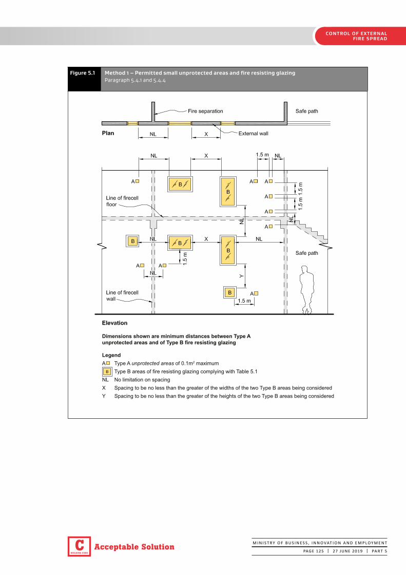
BUILDING CODE
C Acceptable SolutionM I N I S T R Y O F B U S I N E S S , I N N O VAT I O N A N D E M P L O Y M E N T
PAGE 125 | 27 JUNE 2019 | PA R T 5
CONTROL OF EXTERNAL FIRE SPREAD
Figure 5.1 Method 1 – Permitted small unprotected areas and fire resisting glazingParagraph 5.4.1 and 5.4.4
Dimensions shown are minimum distances between Type A unprotected areas and of Type B fire resisting glazing
LegendA Type A unprotected areas of 0.1m2 maximum Type B areas of fire resisting glazing complying with Table 5.1NL No limitation on spacingX Spacing to be no less than the greater of the widths of the two Type B areas being consideredY Spacing to be no less than the greater of the heights of the two Type B areas being considered

BUILDING CODE
CAcceptable SolutionM I N I S T R Y O F B U S I N E S S , I N N O VAT I O N A N D E M P L O Y M E N T
PAGE 126 | 27 JUNE 2019 | PA R T 5
CONTROL OF EXTERNAL FIRE SPREAD
Figure 5.2 Separation of unprotected areasParagraph 5.5.1
(a) ADJOINING FIRECELLS
NOTE: Angle “x” is the angle between the wall and relevant boundaryx

BUILDING CODE
C Acceptable SolutionM I N I S T R Y O F B U S I N E S S , I N N O VAT I O N A N D E M P L O Y M E N T
PAGE 127 | 27 JUNE 2019 | PA R T 5
CONTROL OF EXTERNAL FIRE SPREAD
Minimum distance to unprotected area in Firecell A from boundary
Minimum distance to unprotected area in Firecell B from boundary Refer Table 5.2
NOTE: Angle “X” is the angle between the wall and relevant boundary.
Figure 5.3 Measuring distance to relevant boundary for use in Table 5.2Tables 5.2 and 5.3 and Paragraph 5.5.1

BUILDING CODE
CAcceptable SolutionM I N I S T R Y O F B U S I N E S S , I N N O VAT I O N A N D E M P L O Y M E N T
PAGE 128 | 5 NOVEMBER 2020 | PA R T 5
CONTROL OF EXTERNAL FIRE SPREAD
Table 5.2a
Maximum percentage of unprotected area for external walls for risk groups SM and SI Paragraphs 5.2.8, 5.5.1 a), 5.5.3, 5.5.4
Risk group
Minimum distance
to relevant
boundary (m)1
Percentage of wall area allowed to be unprotected
Angle between wall and relevant boundary
≤ 45°
Angle between wall and relevant boundary
> 45° to ≤ 60°
Angle between wall and relevant boundary
> 60° to < 90°
Width of unsprinklered
firecell (m)
Width of sprinklered firecell (m)
Width of unsprinklered
firecell (m)
Width of sprinklered firecell (m)
Width of unsprinklered
firecell (m)
Width of sprinklered firecell (m)
≤ 5 > 5 ≤ 5 > 5 ≤ 5 > 5 ≤ 5 > 5 ≤ 5 > 5 ≤ 5 > 5
< 1 0 0 0 0 0 0 0 0 0 0 0 0
1 35 30 70 60 45 33 90 66 55 35 100 70
2 55 40 100 80 70 45 100 90 85 55 100
3 80 55 100 95 5 100 100 80
4 100 70 100 90 100
90 100
6 100
< 1 0 0 0 0 0 0
1 70 60 90 66 100 70
2 100 80 100 90 100
3 100 100
Notes:
1. See Figure 5.3
SM
SI
Amend 2Nov 2020
Amend 2Nov 2020

BUILDING CODE
C Acceptable SolutionM I N I S T R Y O F B U S I N E S S , I N N O VAT I O N A N D E M P L O Y M E N T
PAGE 129 | 5 NOVEMBER 2020 | PA R T 5
CONTROL OF EXTERNAL FIRE SPREAD
Table 5.2b
Maximum percentage of unprotected area for external walls for risk group CA Paragraphs 5.2.8, 5.5.1 b), 5.5.3 and 5.5.4
Risk group
Minimum distance
to relevant
boundary (m)1
Percentage of wall area allowed to be unprotected
Angle between wall and relevant boundary
≤ 45°
Angle between wall and relevant boundary
> 45° to ≤ 60°
Angle between wall and relevant boundary
> 60° to < 90°
Width of unsprinklered
firecell (m)
Width of sprinklered firecel (m)
Width of unsprinklered
firecell (m)
Width of sprinklered firecel (m)
Width of unsprinklered
firecell (m)
Width of sprinklered firecell (m)
≤ 10 > 10 ≤ 10 > 10 ≤ 10 > 10 ≤ 10 > 10 ≤ 10 > 10 ≤ 10 > 10
< 1 0 0 0 0 0 0 0 0 0 0 0 0
1 20 20 40 40 20 20 40 40 23 20 46 40
2 22 20 44 40 25 20 50 40 30 22 60 44
3 25 25 50 50 30 25 60 60 39 25 78 50
4 30 30 60 60 40 30 80 60 50 30 100 60
5 40 30 80 60 50 30 100 60 64 40 80
6 45 35 90 70 60 40 80 79 45 90
7 55 40 100 80 70 45 90 90 55 100
8 65 45 90 85 50 100 100 65
9 75 50 100 95 55 75
10 90 55 100 65 90
11 100 65 75 100
12 70 85
13 80 95
14 90 100
15 95
16 100
Notes:
1. See Figure 5.3
CA
Amend 2Nov 2020

BUILDING CODE
CAcceptable SolutionM I N I S T R Y O F B U S I N E S S , I N N O VAT I O N A N D E M P L O Y M E N T
PAGE 130 | 5 NOVEMBER 2020 | PA R T 5
CONTROL OF EXTERNAL FIRE SPREAD
Table 5.2c
Maximum percentage of unprotected area for external walls for risk group WB professional activities, industrial activities, and intermittently occupied buildings and risk group VP Paragraphs 5.2.8, 5.5.1 c), 5.5.3 and 5.5.4
Risk group
Minimum distance
to relevant
boundary (m)1
Percentage of walls allowed to be unprotected
Angle between wall and relevant boundary ≤ 45°
Angle between wall and relevant boundary > 45° to ≤ 60°
Angle between wall and relevant boundary > 60° to < 90°
Width of unsprinklered
firecell (m)
Width of sprinklered firecell (m)
Width of unsprinklered
firecell (m)
Width of sprinklered firecell (m)
Width of unsprinklered
firecell (m)
Width of sprinklered firecell (m)
≤ 10 > 10 ≤ 10 > 10 ≤ 10 > 10 ≤ 10 > 10 ≤ 10 > 10 ≤ 10 > 10
< 1 0 0 0 0 0 0 0 0 0 0 0 0
1 20 20 40 40 20 20 40 40 25 20 50 40
2 25 25 50 50 30 25 60 50 35 25 70 50
3 30 30 60 60 40 30 80 60 40 30 80 60
4 40 35 80 70 50 35 100 70 50 40 100 80
5 50 40 100 80 65 40 80 60 50 100
6 60 50 100 80 50 100 75 60
7 75 55 90 60 90 75
8 90 60 100 70 100 90
9 100 70 80 100
10 80 90
11 90 100
12 100
Notes:
1. See Figure 5.3
WB
VP
Amend 2Nov 2020

BUILDING CODE
C Acceptable SolutionM I N I S T R Y O F B U S I N E S S , I N N O VAT I O N A N D E M P L O Y M E N T
PAGE 131 | 5 NOVEMBER 2020 | PA R T 5
CONTROL OF EXTERNAL FIRE SPREAD
Table 5.2d
Maximum percentage of unprotected area for external walls for risk group WB storage activities Paragraphs 5.2.8, 5.5.1 d), 5.5.3 and 5.5.4
Risk group
Minimum distance to
relevant boundary
(m)1
Percentage of wall area allowed to be unprotected
Angle between wall and relevant boundary
≤ 45°
Angle between wall and relevant boundary
> 45° to ≤ 60°
Angle between wall and relevant boundary
> 60° to < 90°
Width of unsprinklered
firecell (Any width)
Width of sprinklered
firecell (Any width)
Width of unsprinklered
firecell (Any width)
Width of sprinklered
firecell (Any width)
Width of unsprinklered
firecell (Any width)
Width of sprinklered
firecell (Any width)
< 1 0 0 0 0 0 0
1 10 20 15 30 15 30
2 15 30 15 35 15 35
3 20 40 20 40 20 40
4 20 45 25 50 25 50
5 25 50 25 55 30 60
6 30 60 30 60 35 70
7 35 70 35 70 40 80
8 40 80 45 90 50 100
9 40 85 50 100 55
10 45 90 55 65
11 50 100 60 70
12 60 70 80
13 65 80 90
14 70 85 100
15 100 100
Notes:
1. See Figure 5.3
WB
Amend 2Nov 2020

BUILDING CODE
CAcceptable SolutionM I N I S T R Y O F B U S I N E S S , I N N O VAT I O N A N D E M P L O Y M E N T
PAGE 132 | 5 NOVEMBER 2020 | PA R T 5
CONTROL OF EXTERNAL FIRE SPREAD
Table 5.2e
Maximum percentage of unprotected area for external walls for risk group WS Paragraphs 5.2.8, 5.5.1 e), 5.5.3and 5.5.4
Risk group
Minimum distance
to relevant
boundary (m)1
Percentage of wall area allowed to be unprotected
Angle between wall and relevant boundary
≤ 45°
Angle between wall and relevant boundary
> 45° to ≤ 60°
Angle between wall and relevant boundary
> 60° to < 90°
Width of sprinklered firecell (m) Width of sprinklered firecell (m) Width of sprinklered firecell (m)
≤ 20 > 20 ≤ 20 > 20 ≤ 20 > 20
< 1 0 0 0 0 0 0
1 20 20 25 20 25 20
2 30 25 30 30 30 25
3 30 30 35 30 35 30
4 35 35 40 35 40 35
5 40 40 45 40 50 40
6 45 40 50 45 60 50
7 50 50 60 50 70 60
8 60 55 65 60 85 65
9 65 60 80 65 100 75
10 70 65 90 75 90
11 80 70 100 80 100
12 90 80 90
13 100 85 100
14 95
15 100
Notes:
1. See Figure 5.3
WS
Amend 2Nov 2020
Amend 2Nov 2020

BUILDING CODE
C Acceptable SolutionM I N I S T R Y O F B U S I N E S S , I N N O VAT I O N A N D E M P L O Y M E N T
PAGE 133 | 5 NOVEMBER 2020 | PA R T 5
CONTROL OF EXTERNAL FIRE SPREAD
Table 5.3
Maximum size of largest permitted single unprotected area in external walls Paragraphs 5.2.8, 5.5.5 and 5.5.6
Risk group
Minimum distance to
relevant boundary
(m)1
Unsprinklered firecell Sprinklered firecell
Maximum largest single unprotected
area (m2)
Minimum distance to adjacent unprotected
areas (m2)
Maximum largest single unprotected
area (m2)
Minimum distance to adjacent unprotected
areas (m2)
1 1.0 1.0 15 1.5
2 6.0 1.5 35 2.5
3 13 4.5 60 3.5
4 20 5.5 96 4.0
5 29 6.5 139 4.5
6 40 7.5 No restriction No restriction
1 15 1.5
2 35 2.5
3 60 3.5
1 1.0 0.5 15 1.5
2 4.0 1.0 35 2.5
3 10 5.0 60 3.5
4 16 7.0 96 4.0
5 23 8.0 139 4.5
6 31 8.5 No restriction No restriction
7 40 9.5 No restriction No restriction
8 51 11 No restriction No restriction
9 64 13 No restriction No restriction
10 77 13.5 No restriction No restriction
1 15 1.5
2 35 2.5
3 60 3.5
4 96 4.0
5 139 4.5
6 No restriction No restriction
Notes:
1. See Figure 5.3
WS
VP
WB
CA
SI
SM
Amend 2Nov 2020

BUILDING CODE
CAcceptable SolutionM I N I S T R Y O F B U S I N E S S , I N N O VAT I O N A N D E M P L O Y M E N T
PAGE 134 | 5 NOVEMBER 2020 | PA R T 5
CONTROL OF EXTERNAL FIRE SPREAD
Amend 2Nov 2020
BUILDING CODE
C Acceptable SolutionM I N I S T R Y O F B U S I N E S S , I N N O VAT I O N A N D E M P L O Y M E N T
PAGE 135 | 5 NOVEMBER 2020 | PA R T 5
CONTROL OF EXTERNAL FIRE SPREAD
Amend 2Nov 2020

BUILDING CODE
CAcceptable SolutionM I N I S T R Y O F B U S I N E S S , I N N O VAT I O N A N D E M P L O Y M E N T
PAGE 136 | 5 NOVEMBER 2020 | PA R T 5
CONTROL OF EXTERNAL FIRE SPREAD
5.6 Horizontal fire spread from roofs and open sided buildings
5.6.1 For risk groups WB and VP, in buildings other than offices and laboratories where the roof of an unsprinklered firecell is within 1.0 m of a relevant boundary, horizontal fire spread shall be resisted by either:
a) Fire rating (for fire exposure from below) that part of the roof within 1.0 m of the relevant boundary. The FRR shall be based on the property rating for the firecell, except that insulation is not required, or
b) Extending the wall, being a fire separation along or adjacent to the relevant boundary, no less than 450 mm above the roof to form a parapet.
Parapets for unsprinklered firecells
5.6.2 Where sprinklers are not provided, and an area of roof within 1.5 m of the relevant boundary is used for storage of combustible materials or vehicle parking, a parapet shall be provided which extends no less than 1.5 m above the roof level with an FRR according to the property rating of Paragraph 2.3. For risk group VP this parapet shall have an FRR of no less than 30 minutes.
Roof projections
5.6.3 If the external wall is required to have an FRR, the eaves projection shall be constructed with the same FRR as the external wall. Alternatively, the external wall shall be extended to the underside of the roof and the eaves need not be fire rated (see Figure 5.4).
5.6.4 If the external wall is not required to have an FRR, roof eaves projecting from that wall need not be fire rated provided that no part of the eaves construction is closer than 650 mm to the relevant boundary.
5.6.5 If the external wall, on its own, is not required to have an FRR, but roof eaves extend to within 650 mm of the relevant boundary, the total eaves construction and the external wall from which they project shall have FRRs in accordance with Paragraph 2.3 (see Figure 5.4).
Eaves construction includes the guttering or spouting and any other projections from the eaves, although guttering or spouting need not be fire rated.
Open sided buildings
5.6.6 An open sided building may be either a detached building or connected to another building (see Figure 5.5). For the open sided building to be deemed 'detached', the horizontal distance between the other building and the roof of the open sided building shall be no less than:
a) 1.0 m for a roof area exceeding 40 m2, or
b) 0.3 m for a roof no greater than 40 m2.
5.6.7 Open sided buildings (see Figure 5.5), having only a single floor level may be constructed with external walls having 100% unprotected area provided that they:
a) Have no less than two sides completely open to the environment, and
b) Where attached to another building, both buildings are under the control of the same occupancy, and
c) For roof areas > 40 m², open sided buildings shall be no closer to a relevant boundary than:
i) 1.0 m if in risk groups SM, SI, CA or WS, or
ii) 3.0 m if in risk groups WB or VP, and
d) For roof areas ≤ 40 m², open sided buildings shall be no closer than 0.3 m to the relevant boundary.
5.6.8 Where the requirements of Paragraph 5.6.7 cannot be achieved the applicable external wall/s shall comply with all the requirements for the horizontal fire spread from external walls in accordance with Paragraph 5.2.
Floor projections
5.6.9 If a floor projects beyond the face of any part of an external wall which requires a property rating, or any part of the projection is closer than 1.0 m to the relevant boundary, the floor projection shall have the same FRR as the floor inside the external wall, and exposed exterior faces of the projection shall comply with Paragraph 5.8.
VPWB
Amend 2Nov 2020

BUILDING CODE
C Acceptable SolutionM I N I S T R Y O F B U S I N E S S , I N N O VAT I O N A N D E M P L O Y M E N T
PAGE 137 | 27 JUNE 2019 | PA R T 5
CONTROL OF EXTERNAL FIRE SPREAD
Figure 5.4 Eaves projectionParagraphs 5.6.3 and 5.6.5
Separation distances for non-fire rated constructionWhen Ar is no greater than 40 m2, ‘Z’ shall be no less than 0.3 m.When Ar exceeds 40 m2, ‘Z’ shall be no less than 1.0 m.
NOTES:1. This figure applies only to single storey open sided buildings.2. In all cases at least two sides of the perimeter wall shall be completely open to the environment.
Figure 5.5 Open sided buildings – distance and FRR requirementsParagraph 5.6.6

BUILDING CODE
CAcceptable SolutionM I N I S T R Y O F B U S I N E S S , I N N O VAT I O N A N D E M P L O Y M E N T
PAGE 138 | 27 JUNE 2019 | PA R T 5
CONTROL OF EXTERNAL FIRE SPREAD
5.7 Vertical fire spread
Roofs
5.7.1 Sleeping risk groups SM and SI, other property and external exitways shall be protected against vertical fire spread from roofs.
5.7.2 Protection against fire spread shall be achieved using one or more of the following methods:
a) Separation by distance, and/or
b) Fire rating the adjoining external wall, and/or
c) Fire rating all or part of the roof, including its supporting structure, against the threat of fire from the underside, and/or
d) Installing sprinklers in the firecell below the roof.
External exitways over roofs
5.7.3 Subject to Paragraph 3.11, when an external exitway crosses a roof or is above or adjacent to a roof on the same or another building, the roof within 3.0 m of any part of the exitway and all supporting elements shall have an FRR in accordance with Paragraph 2.3.
Primary elements
5.7.4 Primary elements providing support to an area of fire rated roof shall have an FRR of no less than that of the roof.
5.7.5 When supporting an unrated roof:
a) Primary elements such as columns or walls which are required to be fire rated shall be rated from floor level to the underside of the roof framing members, and
b) Any roof framing members connected to these fire rated columns or walls shall also be rated if their collapse in fire would cause the consequential collapse of the rated columns or walls.
Fire spread from an adjacent lower roof
5.7.6 Fire spread from a roof close to and lower than an external wall in the same building (as the lower roof), or in an adjacent building on the same title shall be avoided by compliance with Paragraph 5.7.7 where firecells behind the wall contain:
a) Other property, or
b) Either risk group SI or SM, or
c) Exitways.
5.7.7 Where the distance between any part of an external wall and a lower roof is less than 9.0 m vertically or 5.0 m horizontally (see Figure 5.6), protective measures shall be applied either to the roof as specified in Paragraph 5.7.8 or to the wall as specified in Paragraph 5.7.9.
5.7.8 Roof protection shall be achieved by:
a) Providing sprinklers throughout the building, or
b) Constructing that part of the roof within 5.0 m horizontally of the wall, with an FRR in accordance with Paragraph 2.3 of the firecell below the roof.
5.7.9 External wall protection above an adjacent lower roof shall be provided by constructing the critical part of the wall (closer to the roof than 9.0 m vertically or 5.0 m horizontally (see Figure 5.6)) with an FRR in accordance with Paragraph 2.3.
SISM
SISM

BUILDING CODE
C Acceptable SolutionM I N I S T R Y O F B U S I N E S S , I N N O VAT I O N A N D E M P L O Y M E N T
PAGE 139 | 5 NOVEMBER 2020 | PA R T 5
CONTROL OF EXTERNAL FIRE SPREAD
Figure 5.6 Vertical fire spread for external walls and roofsParagraph 5.7.7 to 5.7.9
Amend 2Nov 2020 throughout the building.

BUILDING CODE
CAcceptable SolutionM I N I S T R Y O F B U S I N E S S , I N N O VAT I O N A N D E M P L O Y M E N T
PAGE 140 | 27 JUNE 2019 | PA R T 5
CONTROL OF EXTERNAL FIRE SPREAD
External fire spread between different levels of the same building
5.7.10 Except where firecells are sprinklered, unprotected areas in external walls shall be protected against vertical fire spread if any of the following conditions occur:
a) An escape height of 4.0 m or more in risk group SM, or
b) Exitways with an escape height of 4.0 m or more in risk group CA or 10 m or more in risk groups WB and VP, or
c) Firecells containing retail areas having an escape height of 7.0 m or more, or
d) Firecells containing other property located one above the other.
5.7.11 If the conditions described in Paragraph 5.7.10 occur, unprotected areas (see Figure 5.7) in the external walls of the firecells shall be separated by no less than:
a) 1500 mm where any parts of the unprotected areas are vertically aligned above one another, or
b) 900 mm where the unprotected areas on one level are horizontally offset from those on the other level.
Spandrels and apron projections
5.7.12 Spandrels may be omitted where an apron projecting no less than 600 mm is constructed. Table 5.4 specifies the acceptable combinations of apron projection and spandrel height.
Figure 5.7 Separation of unprotected areasParagraph 5.7.11
Fire rated wall
900mmminimum
H
Unprotected areas(eg. glazing)
1500mm
2/3 H
H = Height of window
Fire cell B
Fire cell A
SM
VPWB
CA

BUILDING CODE
C Acceptable SolutionM I N I S T R Y O F B U S I N E S S , I N N O VAT I O N A N D E M P L O Y M E N T
PAGE 141 | 5 NOVEMBER 2020 | PA R T 5
CONTROL OF EXTERNAL FIRE SPREAD
Table 5.4 Combination of aprons and spandrels
Apron projection (mm) Spandrel height (mm)
0 1500
300 1000
450 500
600 0
5.7.13 Aprons shall extend horizontally beyond the outer corners of the unprotected area by no less than the apron projection distance. Aprons and spandrels shall have FRRs of no less than that of the floor separating the upper and lower firecells. Spandrels shall be rated from both sides. Aprons need only be rated from the underside.
Roof storage
5.7.14 Storage of combustible materials on a roof is not permitted within 1.5 m of a higher external wall if the adjacent building above contains sleeping risk groups.
Roof vehicle parking
5.7.15 Where a roof used for vehicle parking is within 1.5 m of a higher external wall and the adjacent building above contains sleeping occupancies, external wall protection above the adjacent lower roof shall be provided by constructing the part of the wall (that is closer to the roof than 3.0 m vertically or 1.5 m horizontally) with an FRR of no less than that required from Table 2.3.
5.7.16 Vertical distances shall be measured for vehicle parking from the building roof level. (See Paragraph 5.6.2 for parapet protection against horizontal fire spread.)
VP
VP
Amend 2Nov 2020

BUILDING CODE
CAcceptable SolutionM I N I S T R Y O F B U S I N E S S , I N N O VAT I O N A N D E M P L O Y M E N T
PAGE 142 | 5 NOVEMBER 2020 | PA R T 5
CONTROL OF EXTERNAL FIRE SPREAD
Amend 2Nov 2020

BUILDING CODE
C Acceptable SolutionM I N I S T R Y O F B U S I N E S S , I N N O VAT I O N A N D E M P L O Y M E N T
PAGE 143 | 5 NOVEMBER 2020 | PA R T 5
CONTROL OF EXTERNAL FIRE SPREAD
5.8 External cladding systems
External wall cladding materials
5.8.1 Where external walls are located less than 1.0 m from a relevant boundary, cladding materials shall be:
a) Non-combustible or limited combustible materials; or
b) Tested in accordance with the relevant standard test in Appendix C C7.1 and achieve a Type A classification.
5.8.2 For buildings containing risk group SI, where external walls are located more than 1.0 m from a relevant boundary, cladding materials shall be:
a) Non-combustible or limited combustible materials; or
b) Tested in accordance with the relevant standard test in Appendix C C7.1 and achieve a Type A or Type B classification.
5.8.3 In addition to the requirements in Paragraphs 5.8.1 and 5.8.2, where multi-level buildings have a building height of 10 m or more, cladding materials shall be:
a) Non-combustible or limited combustible materials; or
b) Tested in accordance with the relevant standard test in Appendix C C7.1 and achieve a Type A classification; or
c) Part of an entire external wall cladding system that complies with Paragraph 5.8.4.
External wall cladding systems for multi-level buildings with a building height ≥ 25 m
5.8.4 The entire external wall cladding system shall be:
a) Non-combustible or limited combustible materials; or
b) Classified in accordance with AS 5113 and achieve a EW classification; or
c) Tested in accordance with BS 8414-1 and satisfy the acceptance criteria in BR 135; or
d) Tested in accordance with BS 8414-2 and satisfy the acceptance criteria in BR 135; or
e) Tested in accordance with NFPA 285 and pass, and cladding materials shall be:
i) non-combustible or limited combustible materials; or
ii) tested in accordance with the relevant standard test in Appendix C C7.1 and achieve a Type A classification.
Cavity barriers
5.8.5 The spread of fire through cavities in an external wall shall be avoided by providing cavity barriers at each floor level. Cavity barriers shall comply with the requirements in Paragraphs 4.15.3 to 4.15.5.
Amend 2Nov 2020
Amend 2Nov 2020
Amend 2Nov 2020
SI

BUILDING CODE
CAcceptable SolutionM I N I S T R Y O F B U S I N E S S , I N N O VAT I O N A N D E M P L O Y M E N T
PAGE 144 | 27 JUNE 2019 | PA R T 6
FIREFIGHTING
Part 6: Firefighting
CONTENTS
6.1 Fire and Emergency New Zealand vehicular access
6.2 Information for firefighters
6.3 Firefighting facilities
6.1 Fire and Emergency New Zealand vehicular access
6.1.1 If buildings are located remotely from the street boundaries of a property, pavements situated on the property and likely to be used by Fire and Emergency New Zealand vehicles to reach a hard-standing shall:
a) Be able to withstand a laden weight of up to 25 tonnes with an axle load of 8 tonnes or have a load-bearing capacity of no less than the public roadway serving the property, whichever is the lower, and
b) Be trafficable in all weathers, and
c) Have a minimum width of 4.0 m, and
d) Provide a clear passageway of no less than 3.5 m in width and 4.0 m in height at site entrances, internal entrances and between buildings, and
e) Provide access to a hard-standing from which there is an unobstructed path to the building within 20 m of:
i) the firefighter access into the building, and
ii) the inlets to fire sprinkler systems or building fire hydrant systems, where these are installed.
6.1.2 For risk group SI only, the following requirements shall be met in addition to those in Paragraph 6.1.1:
a) Roadway pavements shall withstand a vehicle of multiple axles spaced at no less than 2.5 m centres, and each carrying 8.2 tonnes, and
b) Where a property includes two or more buildings, any one of which has a building height greater than 7.0 m, roadway widths shall be no less than 6.5 m, corners and bends shall have a minimum radius of 12.5 m and turning areas shall be a minimum of 25 m from wall to wall, and
c) Hard-standings shall be provided adjacent to any building having a building height greater than 7.0 m.
6.1.3 For risk group SI only, the location and extent of hard-standings shall be determined in consultation with Fire and Emergency New Zealand.
6.2 Information for firefighters
6.2.1 If fire alarm or sprinkler systems are installed, the control panel shall be located in a position close to the Fire and Emergency New Zealand attendance point and in accordance with NZS 4512, NZS 4515 and NZS 4541 as appropriate.
6.2.2 If hazardous substances are present in the building, warning signage in accordance with F8/AS1 shall be displayed.
SI
SI
BUILDING CODE
C Acceptable SolutionM I N I S T R Y O F B U S I N E S S , I N N O VAT I O N A N D E M P L O Y M E N T
PAGE 145 | 27 JUNE 2019 | PA R T 6
FIREFIGHTING
6.3 Firefighting facilities
6.3.1 The control features of fire safety systems shall be located at a position with ready access from street level and protected from the effects of fire including debris falling from upper floors.
Fire hydrant system
6.3.2 Building fire hydrant systems shall be installed as specified in Paragraph 2.2 and shall meet the requirements of NZS 4510.
Fire and Emergency New Zealand lift control
6.3.3 Fire and Emergency New Zealand lift control is required if the escape height exceeds 10 m. The control of lifts under fire conditions shall comply with NZS 4332.
BUILDING CODE
CAcceptable SolutionM I N I S T R Y O F B U S I N E S S , I N N O VAT I O N A N D E M P L O Y M E N T
PAGE 146 | 5 NOVEMBER 2020 | PA R T 7
PREVENTION OF FIRE OCCURRING
Part 7: Prevention of fire occurring
CONTENTS
7.1 Solid fuel appliances
7.2 Gas-burning appliances
7.3 Oil-fired appliances
7.4 Electrical fire safety
7.5 Open fires
The design, construction and/or installation of certain types of fixed appliances using controlled combustion and other fixed equipment is specified as follows.
7.1 Solid fuel appliances
7.1.1 AS/NZS 2918, with the modifications given in Paragraph 7.1.2, is an Acceptable Solution for the installation of:
a) Domestic solid fuel burning appliances installed in either domestic or commercial situations, and
b) Flue systems.
7.1.2 Modifications to AS/NZS 2918
Delete Paragraph 3.8 and substitute the following:
“3.8 Seismic restraint
The appliance and the floor protector shall be mechanically fixed to the floor itself.
The test seismic force shall be taken as the application of a horizontal force equal to 0.40 times the appliance weight acting in any direction at the mid height of the combustion chamber. The appliance shall not move, tilt or be dislodged from its installed position during the application of the test force.
The weight of the flue system and a wetback, if fitted, shall not be included in the test.”
Delete Section 7 and substitute the following:
“7.1 Ventilation
Ventilation shall be in accordance with Acceptable Solution G4/AS1.
7.2 Water heating equipment
Water heating appliances installed in conjunction with the heating appliance shall be vented and shall comply with Acceptable Solution G12/AS1.”
7.2 Gas-burning appliances
7.2.1 Gas-burning appliances must be installed in accordance with NZBC Clause G11.
Amend 2Nov 2020
Amend 2Nov 2020
BUILDING CODE
C Acceptable SolutionM I N I S T R Y O F B U S I N E S S , I N N O VAT I O N A N D E M P L O Y M E N T
PAGE 147 | 5 NOVEMBER 2020 | PA R T 7
PREVENTION OF FIRE OCCURRING
7.3 Oil-fired appliances
7.3.1 AS 1691, with the modifications given in Paragraph 7.3.2, is an Acceptable Solution for the installation of domestic oil-fired appliances.
7.3.2 Modifications to AS 1691
Delete Paragraph 2.2.3 and substitute the following:
“2.2.3 Electrical equipment
Electrical equipment shall comply with Acceptable Solution G9/AS1 or Verification Method G9/VM1.”
Delete “CSIRO durability Class 2 or better” from Paragraph 3.1.2 (b) and substitute “H5 treatment”.
Delete the Note to Paragraph 3.1.2 (d).
Delete Paragraph 3.1.4 and substitute the following:
“3.1.4 Stability
The appliance shall be mechanically fixed to the building.
The test seismic force on the fuel tank shall be taken as the application of a horizontal force in kilograms numerically equal to 0.40 times the tank volume in litres acting at the centre of the tank. The test seismic force on the appliance shall be taken as the application of a horizontal force equal to 0.40 times the appliance operating weight acting at the centre of the appliance.
The appliance and the fuel tank shall resist their respective seismic forces with no significant movement.”
Delete the words “without specific approval” from Paragraph 3.2.8 (b).
Delete Paragraph 5.1.1.
Add the following Note to 5.2.2:
“Note: Refer to Acceptable Solution G4/AS1 for ventilation requirements.”
7.3.3 AS/NZS 2918 Sections 2 and 4 are also Acceptable Solutions for the installation of flues for domestic oil-fired appliances.
7.4 Electrical fire safety
7.4.1 Electrical installations in buildings must be installed in accordance with NZBC Clause G9.
Amend 2Nov 2020

BUILDING CODE
CAcceptable SolutionM I N I S T R Y O F B U S I N E S S , I N N O VAT I O N A N D E M P L O Y M E N T
PAGE 148 | 27 JUNE 2019 | PA R T 7
PREVENTION OF FIRE OCCURRING
Table 7.1 Minimum acceptable dimensions of chimneys
Chimney construction Chimney jamb and chimney back thickness Chimney breasts and side gathering and chimney wall thickness above the level of the gather, excluding linings (mm)
Excluding filling and flue liner (mm)
Including filling and flue liner (mm)
Concrete 170 255 170
Brickwork 155 230 155
Precast pumice concrete
85 170 85
7.5 Open fires
Chimneys
7.5.1 Chimneys shall be constructed in accordance with Table 7.1 and Figure 7.1. They shall have:
a) Fireplaces lined with fire bricks having a thickness of no less than 50 mm
b) Fireplace joints of non-combustible material and shall be sealed against air leakage
c) Chimney brickwork of no less than a single skin of brick 90 mm thick plus a 65 mm thick layer of grout, and
d) An expansion gap provided in chimneys containing flue liners. These flue liners shall be wrapped in a combustible material of thickness no less than 0.25 mm (e.g. heavy-quality building paper) to prevent the grout filling from bonding with the flue liner.
7.5.2 Cross-sectional areas of flues shall be no less than 0.03 m2 for an open fireplace (see Figure 7.2).

BUILDING CODE
C Acceptable SolutionM I N I S T R Y O F B U S I N E S S , I N N O VAT I O N A N D E M P L O Y M E N T
PAGE 149 | 27 JUNE 2019 | PA R T 7
PREVENTION OF FIRE OCCURRING
Figure 7.1 Chimney terms and dimensionsParagraph 7.5

BUILDING CODE
CAcceptable SolutionM I N I S T R Y O F B U S I N E S S , I N N O VAT I O N A N D E M P L O Y M E N T
PAGE 150 | 27 JUNE 2019 | PA R T 7
PREVENTION OF FIRE OCCURRING
7.5.3 Flue liners shall be one of the following types:
a) Clay flue liners with rebated or socketed joints, or
b) Imperforate clay pipes with socketed joints, or
c) High alumina cement and kiln-burnt aggregate pipes, with rebated or socketed joints, or steel collars around joints.
The flue liners shall be fitted with the sockets or rebates uppermost to prevent condensate running out, and to prevent any caulking material from being adversely affected. Joints between the flue liners, and any space between flue liners and the masonry, shall be filled with weak mortar or insulating concrete (see Figure 7.2(a)).
7.5.4 Flue liners are not required for:
a) Brick chimneys if constructed of two 90 mm skins of brickwork with a 65 mm grout-filled gap between (see Figure 7.2 b)), or
b) Ordinary concrete chimneys, or
c) Precast pumice concrete chimneys.
7.5.5 Clearance above roofs shall be in accordance with AS/NZS 2918 Figure 4.9.
7.5.6 Every fireplace shall have a separate flue.
7.5.7 Flue joints shall be of non-combustible material and sealed against air leakage.
7.5.8 Hearths for fireplaces shall:
a) Be constructed of fully grouted stones, bricks or concrete of no less than 50 mm total thickness,
b) Extend no less than 230 mm on each side of the fireplace opening, and no less than 380 mm forward of the fireplace opening, and
c) Have no combustible material closer than the clearances given in Paragraph 7.5.8 b) from the upper and lower surfaces of the hearth.
7.5.9 Clearances between a chimney and any combustible material (see Figure 7.3) shall be no less than:
a) 200 mm at any opening in the flue, or at the fireplace opening, and
b) 200 mm above or below the upper surface of the hearth, and 75 mm from the lower surface of the hearth.
7.5.10 Hearth edges are to be separated from combustible material with insulating material having a minimum service operating temperature of 150°C.
7.5.11 A ventilated space of no less than 50 mm shall be provided between the outer face of a fireplace, chimney or flue and any combustible material.
7.5.12 AS/NZS 2918 Sections 2 and 4 are also Acceptable Solutions for the installation of flues from open fires.

BUILDING CODE
C Acceptable SolutionM I N I S T R Y O F B U S I N E S S , I N N O VAT I O N A N D E M P L O Y M E N T
PAGE 151 | 27 JUNE 2019 | PA R T 7
PREVENTION OF FIRE OCCURRING
Figure 7.2 Brick chimney flues – sectionsParagraphs 7.5.2 and 7.5.4

BUILDING CODE
CAcceptable SolutionM I N I S T R Y O F B U S I N E S S , I N N O VAT I O N A N D E M P L O Y M E N T
PAGE 152 | 27 JUNE 2019 | PA R T 7
PREVENTION OF FIRE OCCURRING
Figure 7.3 Clearance between a chimney and hearth, and combustible materialsParagraph 7.5.9
Hearth edges are to be separated from combustible material with insulating material (refer to Paragraph 7.5.10).
BUILDING CODE
C Acceptable Solution
FIRE SAFETY SYSTEMS
M I N I S T R Y O F B U S I N E S S , I N N O VAT I O N A N D E M P L O Y M E N T
PAGE 153 | 27 JUNE 2019 | APPENDIX A (NORMATIVE)
Appendix A (normative): Fire safety systems
A1.1 Fire alarm and sprinkler systems
A1.1.1 Fire alarm systems used in fire safety systems shall satisfy the requirements of Acceptable Solution F7/AS1. Fire sprinkler systems used in fire safety systems shall, except where specified, also satisfy the requirements of Appendix B.
A1.2 Requirements common to alarm systems
A1.2.1 All fire alarm systems (except for domestic smoke alarm systems), unless otherwise specified and regardless of their means of activation, shall be provided with a means of communication with Fire and Emergency New Zealand in accordance with Acceptable Solution F7/AS1.
A2.1 Fire safety system descriptions
A2.1.1 The following text provides a brief description of fire safety systems not otherwise described in Acceptable Solution F7/AS1. See F7/AS1 for descriptions of fire alarm systems Types 1, 2, 3, 4, 5, 6 and 7, and Table 2.2 of this Acceptable Solution.
Type 9 – Smoke control in air-handling systems
Where smoke control is required in relation to heating, ventilating or air conditioning systems, it shall comply with the requirements of either:
a) AS/NZS 1668.1 for HVAC system shutdown and interface with any Type 4 or 7 system, or
b) NZS 4512 to provide ancillary function output for HVAC system shutdown if a Type 4 or 7 alarm system is used as a means of smoke detection.
Type 15 – Fire and Emergency New Zealand Lift Control
The control of lifts under fire conditions shall comply with NZS 4332.
Type 18 – Fire hydrant systems for buildings
Fire hydrant systems shall comply with NZS 4510.

BUILDING CODE
CAcceptable Solution
FIRE SPRINKLER
M I N I S T R Y O F B U S I N E S S , I N N O VAT I O N A N D E M P L O Y M E N T
PAGE 154 | 27 JUNE 2019 | APPENDIX B (NORMATIVE)
Appendix B (normative): Fire sprinkler systems
B1.1 Introduction
B1.1.1 Wherever sprinklers are required by this Acceptable Solution, they shall comply with the relevant New Zealand Standard, amended as shown in Paragraphs B2.1 and B3.1.
B2.1 Automatic fire sprinkler systems
B2.1.1 NZS 4541 is amended as follows:
Clause 103 Definitions
Sprinkler system A system including:
(a) to (i) No change.
(j) Delete.
(k) Delete.
(l) No change.
Clause 205 Delete entire clause.
Clause 209 Delete entire clause.
Clause 1203 Routine Surveys
Clause 1203.1
Delete first two paragraphs and replace with:
“It is important that a sprinkler system at all times complies with this Standard as amended by Paragraph B2.1 of Appendix B to C/AS2 in all respects. To ensure that building alterations, changes in process or storage patterns or progressive deterioration of system components do not prejudice system compliance, a comprehensive survey shall be carried out biennially at intervals not exceeding 28 months. Such surveys shall be carried out by an independent qualified person.”
B3.1 Residential fire sprinkler systems
B3.1.1 NZS 4515 is amended as follows:
Clause 1.5 Definitions
Sprinkler system A system including:
(a) to (g) No change.
(h) Delete.
Clause 1.11 Delete entire clause.
Clause 2.1.2 Delete.
Clause 2.1.3 Delete.

BUILDING CODE
C Acceptable Solution
TEST METHODS
M I N I S T R Y O F B U S I N E S S , I N N O VAT I O N A N D E M P L O Y M E N T
PAGE 155 | 5 NOVEMBER 2020 | APPENDIX C (NORMATIVE)
Appendix C (normative): Test methods
C1.1 General
This Appendix contains test methods for confirming that specific building elements satisfy relevant provisions of this Acceptable Solution for Protection from Fire. It includes both established standard tests and other test methods for building elements in situations where standard tests are unavailable.
If these specific building elements have been tested to a version of a Standard in force at the date of testing and a later version of that Standard has been incorporated by reference in this Acceptable Solution, retesting is not required.
C2.1 Flammability of floor coverings
Materials shall be assigned a critical radiant flux via either:
a) Testing to ISO 9239 Reaction to fire tests for flooring– Part 1: Determination of the burning behaviour using a radiant heat source, or
b) Adequacy, determined through following the methodology in C/VM2 Appendix B Table B1.
C3.1 Flammability of suspended flexible fabrics and membrane structures
Materials shall be assigned a flammability index when tested to:
a) AS 1530 Methods for fire tests on building materials and structures – Part 2: Test for flammability of materials.
C4.1 Properties of lining materials
C4.1.1 Combustibility test
Materials shall be classified as:
a) Non-combustible or combustible when tested to AS 1530 Methods for fire tests on building materials and structures – Part 1: Combustibility test for materials; or
b) Non-combustible when classified as A1 in accordance with BS EN 13501-1 Fire classification of construction products and building elements – Part 1:2018 Classification using test data from reaction to fire tests; or
c) Limited combustible when classified as A2 in accordance with BS EN 13501-1 Fire classification of construction products and building elements – Part 1:2018 Classification using test data from reaction to fire tests.
C4.1.2 Material for internal surface linings shall be given a Group Number in accordance with Appendix A of C/VM2 via one the following methods:
a) Testing to ISO 5660 Reaction-to-fire tests – Part 1: Heat release rate (cone calorimeter method), and Part 2 Smoke production rate (dynamic method), or
b) Testing to ISO 9705 Fire tests – Full scale room test for surface products, or
c) Equivalency determined through an approved alternative test or classification method as provided in Table C1.1, or
d) Adequacy may be determined by applying the values in Table C1.2.
Amend 2Nov 2020
Amend 2Nov 2020

BUILDING CODE
CAcceptable Solution
TEST METHODS
M I N I S T R Y O F B U S I N E S S , I N N O VAT I O N A N D E M P L O Y M E N T
PAGE 156 | 27 JUNE 2019 | APPENDIX C (NORMATIVE)
Table C1.1 Alternative test or classification standards for Group Numbers
Requirements according to C/VM2 Appendix A using ISO 9705 or ISO 5660
Australian requirements according to NCC Specification C1.10 Clause 4 using AS ISO 9705
European Classification using EN 13501-1
Group Number 1-S Group Number 1, and a smoke growth rate index not more than 100
Class A1, A2 or
Class B and smoke production rating s1 or s2
Group Number 1 Group Number 1 Class A1, A2 or B
Group Number 2-S Group Number 2, and a smoke growth rate index not more than 100
Class C and smoke production rating s1 or s2
Group Number 2 Group Number 2 Class C
Group Number 3 Group Number 3 Class D
Group Number 4 Group Number 4 Class E and F
Table C1.2 Specified performances for some substrate and coating combinations
Coating (coating in good condition and well adhered to substrate)
Substrate Group Number
Waterborne or solvent borne paint coatings ≤ 0.4 mm thick
Polymeric films ≤ 0.2 mm thick
Concrete and masonry ≥ 15 mm thick
Sheet metal ≥ 0.4 mm thick
Fibre-cement board ≥ 6.0 mm thick
Porcelain, ceramic, glass, solid stone or similar tiles
1-S
Waterborne or solvent borne paint coatings ≤ 0.4 mm thick
Gypsum plasterboard with or without paper facing
≥ 9.5 mm thick
2-S
Waterborne or solvent borne paint coatings, varnish or stain
≤ 0.4 mm thick
≤ 100 g/m2
Solid wood or wood product
≥ 9.0 mm thick
≥ 600 kg/m3 for particle boards, or
≥ 400 kg/m3 for all other wood and wood products
3
Note: The requirements of this table do not apply to metal faced panels with polymeric substrate.

BUILDING CODE
C Acceptable Solution
TEST METHODS
M I N I S T R Y O F B U S I N E S S , I N N O VAT I O N A N D E M P L O Y M E N T
PAGE 157 | 27 JUNE 2019 | APPENDIX C (NORMATIVE)
C5.1 Fire resistance
C5.1.1 Primary elements and secondary elements, closures and fire stops shall be assigned a fire resistance rating (FRR) when tested to:
a) AS 1530 Methods for fire tests on building materials and structures – Part 4: Fire resistance tests of elements of building construction, or
b) NZS/BS 476 Fire tests on building materials and structures – Parts 21 and 22.
C5.1.2 Fire stops shall be tested:
a) In circumstances representative of their use in service, paying due regard to the size of expected gaps to be fire stopped, and the nature of the fire separation within which they are to be used, and
b) In accordance with AS 4072: Components for the protection of openings in fire resistent separating elements – Part 1: Service penetrations and control joints.
C6.1 Fire doors and smoke control doors
C6.1.1 Fire doors shall be evaluated in circumstances representative of their use in service, and shall comply with NZS 4520 Fire-resistant doorsets.
Smoke control doors
C6.1.2 A door shall be deemed to be a smoke control door if, in addition to the requirements in this Acceptable Solution for smoke control doors:
a) The door is a fire door that is fitted with appropriate smoke seals, or
b) It is constructed with solid core leaves. Solid timber core leaves, when used, shall have a leaf thickness of no less than 35 mm, and
c) It is provided with smoke seals as required by this Acceptable Solution. Smoke seals shall be in continuous contact with the mating element, and located so as to minimise interruption by hardware, and
d) The frames are constructed of timber, and the jambs are no less than 30 mm thick, and
e) Any vision panel cut-outs are no less than 150 mm from the leaf edges, and
f) The maximum average clearances (excluding pre-easing) are
i) Leaf to frame 3 mm
ii) Leaf to leaf 5 mm
iii) Leaf to top of any floor covering 10 mm, and
g) Any additional facings are adhesive fixed, and
h) It is provided with signage identifying it as a smoke control door in accordance with Acceptable Solution F8/AS1.
Frictional forces
C6.1.3 The forces required to open any fire door or smoke control door on an escape route shall not exceed 67 N to release the latch, 133 N to set the door in motion, and 67 N to open the door to the minimum required width. These forces shall be applied at the latch stile.
These requirements do not apply to horizontal sliding doors in risk group SI or to power-operated doors.
Self-closing provision
C6.1.4 All fire and smoke control door leaves shall be self-closing, and provision shall be made for the self-closing device to be adjustable during commissioning to satisfy the requirements of Paragraph C6.1.3 after installation.
C6.1.5 Where it is desirable in normal circumstances for a fire door or smoke control door to operate freely, it is acceptable to use a self-closer mechanism which activates in the event of fire but does not operate at other times.
Automatic smoke-sensing devices
C6.1.6 Automatic smoke-sensing devices complying with NZS 4512, if used, shall be positioned within the stream of air that passes the door when the smoke control door is fully open.
SI

BUILDING CODE
CAcceptable Solution
TEST METHODS
M I N I S T R Y O F B U S I N E S S , I N N O VAT I O N A N D E M P L O Y M E N T
PAGE 158 | 5 NOVEMBER 2020 | APPENDIX C (NORMATIVE)
C7.1 Fire properties of external wall cladding systems
C7.1.1 Cladding materials shall be classified using the values in Table C1.3 when tested in accordance with:
a) ISO 5660 Reaction-to-fire tests – Heat release, smoke production and mass loss rate – Part 1: Heat release rate (cone calorimeter method), or
b) AS/NZS 3837 Method of test for heat and smoke release rates for materials and properties using an oxygen consumption calorimeter.
C7.1.2 In addition to meeting the general requirements of ISO 5660 Part 1 or AS/NZS 3837, testing shall be in accordance with the following specific requirements:
a) An applied external heat flux of 50 kW/m2, and
b) A test duration of 15 minutes, and
c) The total heat release measured from start of the test, and
d) Sample orientation horizontal, and
e) Ignition initiated by the external spark igniter.
C7.1.3 Timber claddings which have a fire retardant treatment incorporated in or applied to them shall be subjected to the regime of accelerated weathering described in ASTM D 2898 Method B with the water flow rate from Method A before testing in accordance with the requirements of Paragraph C7.1.1.
Table C1.3 Classification of cladding materialsC7.1.1
Cladding material type Peak heat release rate (kW/m2) Total heat released (MJ/m2)
Type A ≤ 100 ≤ 25
Type B ≤ 150 ≤50Amend 2Nov 2020
Amend 2Nov 2020
Amend 2Nov 2020
Amend 2Nov 2020
C7.1.4 Claddings incorporating a metal facing with a melting point of less than 750°C covering a combustible core or insulant shall be tested as described in Paragraph C7.1.2 without the metal facing present.
Amend 2Nov 2020