carveraudio - carvermanuals.com owners.pdf · carveraudio.com a website devoted to the legacy of...
TRANSCRIPT

CARVERaudio.com A Website Devoted to the Legacy of Bob Carver's Electronics
This, and all manuals found on CARVERaudio.com have been painstakingly scanned, compiled, cataloged and archived by our dedicated forum members, for the benefit of all Carver audio fanatics.
These manuals are NOT intended for re‐sale. If you should find these manuals “For Sale” on any website, please report your findings to us, so we may have them removed.
CARVERaudio.com
This manual is provided free, courtesy of CARVERaudio.com
Please report any sales of this manual to our forum @ www.CARVERaudio.com

DECLARATION OF CONFORMITY
We PHOENIX GOLD INTERNATIONAL, INC.(supplier’s name)
9300 N. DECATUR, PORTLAND, OR 97203 USA(address)
declare under our sole responsibility that the productpm125/420
(name, type or model, lot, batch or serial number, possibly sources and numbers of items)to which this declaration relates is in conformity with the following standard(s) or other normative document(s)
EN55013, EN55020, EN60065(title and /or number and date if issue of the standard(s) or other normative document(s)
(if applicable) following the provisions of89/336/EEC/73/23 EEC
DirectivePORTLAND,OR USAApril 25, 1997
(Place and date of issue)
(name and signature or equivalentmarking of authorized person)
A Division Of Phoenix Gold International, Inc.
Part #8100.0088B
5Year Warranty
18 0DAYPerformance
Guarantee Made In America
9300 North Decatur Portland OR 97203 Tel: 503.288.2008 Fax: 503.978.3302
p m 1 2 5 / p m 4 2 0Professional Stereo Power Amplifier
This manual is provided free, courtesy of CARVERaudio.com
Please report any sales of this manual to our forum @ www.CARVERaudio.com

CAUTIONRISK OF ELECTRIC SHOCK
DO NOT OPEN
CAUTION: TO REDUCE THE RISK OF ELECTRIC SHOCK
DO NOT REMOVE COVER (OR BACK)
NO USER-SERVICEABLE PARTS INSIDE
REFER SERVICING TO QUALIFIED SERVICE PERSONNEL
The lightning flash with arrowhead symbolwithin an equilateral triangle is intended to alertthe user to the presence of uninsulated"dangerous voltage" within the product'senclosure, that may be of sufficient magnitudeto constitute a risk of electric shock to persons.
The exclamation point within an equilateraltriangle is intended to alert the user of thepresence of important operating and main-tenance (servicing) instructions in the literatureaccompanying the appliance.
Introduction ............................................................1Unpacking and Paperwork .....................................1Features and Specifications
pm125.................................................................2pm420.................................................................4
Controls and Functions...........................................6Installation
Location and General Precautions............................................8Mechanical Considerations ................................8Rear Support for Road Applications ..............................................8Thermal Considerations......................................8AC Power Considerations..................................9Magnetic Leakage Considerations....................................................9
Installation (continued)Input Wiring........................................................9Input Sensitivity................................................10Output Wiring...................................................10Polarity..............................................................10Dual Mono........................................................10Bridged Mono...................................................11Parallel Mono ...................................................11Clipping Eliminator..........................................11
Operating TipsUsing the pm125/pm420..................................12
Servicing Instructions...........................................13In Case of Difficulty.............................................14Care and Service Assistance.................................15Warranty Information ...........................................16
Safety Information
Table Of Contents
IntroductionCongratulations on your purchase of a new Carver Professional Power Amplifier. It is backed bystate-of-the-art engineering and manufacturing techniques to bring you the best in qualitycraftsmanship and reliable performance. The pm125 and pm420 are specially designed for prosound applications. Their rugged construction and low profile make them ideal for sustaining theabuses of the road with reliability and space-saving economy. And their accurate sound andample power make them ideal for critical studio applications as well. The pm125 is rated at 62 watts perchannel into 4 ohms and 50 watts per channel into 8 ohms. In bridged mono operation it is rated at 125watts into 8 ohms. The pm420 is rated at 210 watts per channel into 4 ohms and 135 watts per channelinto 8 ohms. In bridged mono operation it is rated at 420 watts into 8 ohms. The sophisticated protectioncircuits designed into these amplifiers will protect your system should an unexpected fault occur. Theyalso protect the amplifiers from excessive temperature, continuous current limiting and shorted outputs.The balanced input uses a high quality, high common-mode rejection differential amplifier forexceptional hum and noise rejection. These power amplifiers were designed and manufactured by peoplewith a lifetime commitment to providing the world’s finest components for music and soundreproduction. Thanks for placing your confidence in Carver Professional. We know your amplifier willprovide many years of dependable service and reliable sound reproduction.
Unpacking andPaperwork
Carefully unpack the amplifier and keep the original carton and packing materials for future moving,shipment or long-term storage. After opening the box, please check for any visible signs of damage thatwere not apparent from the outside of the box. If you do encounter what appears to be concealed damage,please consult your Carver Professional Dealer before installing the unit.
Important PaperworkMake sure to save your sales receipt. Your receipt is extremely important to establish the duration of yourLimited Warranty and for insurance purposes. Next, make a note of the serial number which is located onthe back of the amplifier. Record it in the space provided below for convenient reference.
Model_________ pm125_______ pm420Serial Number: _____________________Purchased at: ______________________Date: _____________________________
F i n a l l y, take a moment to fill out and return the Warranty Registration Card packed with the amplifier andreturn it to Carver Professional. This will allow us to keep you informed about new products as theybecome available.
5
This manual is provided free, courtesy of CARVERaudio.com
Please report any sales of this manual to our forum @ www.CARVERaudio.com

pm125
76
• 50W per channel into 8 ohms62W per channel into 4 ohms125W mono into 8 ohms
• 1/4-inch TRS input jacks
• Accepts balanced or unbalanced lines
• Multi-way binding post output connectors
• Independent 11 detent Level Controls for CH1 & CH2
• Dual Mono mode for operating both channels with amono signal
• Bridged Mono mode for combining the power ofboth channels into a single higher-powered channel
• Input sensitivity set at 1.5V RMS from factory.Internally reconfigurable to 0.775V RMS.
• Internal jumpers to bypass Left and Right ChannelLevel Controls
• Independent CH1/CH2 speaker relays willinstantaneously disconnect if one of the followingfault conditions is detected:
D.C. OffsetOver TemperatureShort Circuit
• Additional protection circuitry includes:Clipping EliminatorResettable Circuit Breaker
• Power Ready, Signal Present and Clip /Protectindicators for each channel
• Headphone jack
• Convection cooled
• 70V transformer option
• CE 1997 approved
Continuous Average Output Power, bothchannels driven:50 watts per channel into8 ohms at 1kHz, with nomore than 0.1% THD62 watts per channel into4 ohms at 1kHz, with nomore than 0.1% THD
Bridged-mono operation:125 watts into 8 ohms at1kHz, with no more than0.1% THD
Dynamic Headroom:>2dB
Frequency Response:20Hz to 20kHz (±0.75dB )
Channel Separation:>55dB @ 1kHz
Damping Factor: <400Input Impedance: 22 Kohms unbalanced,
44 Kohms balancedSensitivity: Low: 1.5VRMS for rated
power into 4 ohms at1kHz, 193mVRMS for 1Winto 4 ohms @ 1kHzHigh: 0.775VRMS for ratedpower into 4 ohms @1kHz, 100mVRMS for 1Winto 4 ohms @ 1kHz
Gain: High: 26.0dB (±0.5dB)Low: 20.3dB (±0.5dB)
Input Overload: +18dBµTHD: <0.1%IM Distortion: <0.1%Signal-to-Noise Ratio:
>100dB, A-weighted,referenced to rated powerinto 4 ohms
Headphone Output:3.0VRMS into 60Ω(150mW) 11.3VRMS into600Ω (213mW)
Slew Rate: >10V/µSCMRR: >40dB @ 1kHz Power Consumption:
250W at full power into 4ohms (continuous)
Power Requirements:120VAC/60Hz (USA andCanada) Other voltagesas required for export
Display: 3 LED indicators perchannel: READY, SIGNAL,CLIP/PROTECT
Size (H x W x D): 1.75˝ (1U) x 19˝ x 13.25˝44mm x 483mm x 337mm
Net Weight: 13.8 lbs. (6.3 kgs)Shipping Weight: 17 lbs. (7.73 kgs)
Due to ongoing continuous product developmentfeatures, specifications, and availability are subjectto change without notice.
This manual is provided free, courtesy of CARVERaudio.com
Please report any sales of this manual to our forum @ www.CARVERaudio.com

Continuous Average Output Power, bothchannels driven:135 watts per channelinto 8 ohms from 20Hz to20kHz, with no more than0.1% THD 210 watts per channelinto 4 ohms at 1kHz, withno more than 0.1% THD
Bridged-mono operation: 420 watts into 8 ohms at1kHz, with no more than0.1% THD
Dynamic Headroom:1.4dB @ 4 ohms
Frequency Response:20Hz to 20kHz (±0.75dB)
Channel Separation: >55dB @ 1kHz
Damping Factor: <400Input Impedance: 22 Kohms unbalanced,
44 Kohms balancedSensitivity: Low: 1.5VRMS for rated
power into 4 ohms at1kHz 106mVRMS for 1Winto 4 ohms @ 1kHzHigh: 0.775VRMS for ratedpower into 4 ohms @1kHz, 55mVRMS for 1Winto 4 ohms @ 1kHz
Gain: High: 31.2dB (±0.5dB)Low: 25.5dB (±0.5dB)
Input Overload: +18dBµIM Distortion: <0.1%Signal-to-Noise Ratio:
>100dB, A-weighted,referenced to rated powerinto 4 ohms
Slew Rate: >10V/µSCMRR: >44dB @ 1kHzPower Consumption:
1000W at full power into4 ohms
Power Requirements:120VAC/60Hz (USA andCanada) Other voltagesas required for export
Display: LED ladder, 3 indicatorsper channel: READY,SIGNAL, CLIP /PROTECT
Size (H x W x D): 3.50˝ (2U) x 19˝ x 13.25˝89mm x 483mm x 337mm
Net Weight: 23.8 lbs. (10.8 kgs)Shipping Weight: 28 lbs. (12.73 kgs)
Due to ongoing continuous product developmentfeatures, specifications, and availability are subjectto change without notice.
pm420• 135W per channel into 8 ohms
210W per channel into 4 ohms420W mono into 8 ohms
• 1/4-inch TRS input jacks
• Accepts balanced or unbalanced lines
• Multi-way binding post outputs
• Independent 11 detent Level Controls for CH1 & CH2
• Dual Mono mode for operating both channels with amono signal
• Bridged Mono mode for combining the power ofboth channels into a single higher-powered channel
• Input sensitivity set at 1.5V RMS from factory.Internally reconfigurable to 0.775V RMS.
• Internal jumpers to bypass Left and Right ChannelLevel Controls
• Independent CH1 /CH2 2 Speaker relays willinstantaneously disconnect if one of the followingfault conditions is detected:
D.C. OffsetOver TemperatureShort Circuit
• Additional protection circuitry includes:Clipping EliminatorResettable Circuit Breaker
• Power Ready, Signal Present and Clip /Protectindicators for each channel
• Convection cooled
• 70V transformer option
• CE 1997 approved
8 9
This manual is provided free, courtesy of CARVERaudio.com
Please report any sales of this manual to our forum @ www.CARVERaudio.com

5. CH1 /CH2 LEVEL CONTROLSThese controls are used to adjust the input level of each channel. When the controls are fully clockwise theamplifier operates at maximum gain. Turning the controls counter-clockwise attenuates the input signal.The LEVEL controls can be bypassed by moving the jumpers located at J15 and J16, next to the LEVELpots on the amplifier’s main circuit board. Plugging the jumper leads into sockets 1 and 2 will bypass theLEVEL controls, locking the amplifier into full gain (as if the LEVEL pots were fully clockwise).The depth of the LEVEL controls can be changed by physically removing the pots from the amplifier boardand moving them to a second set of holes in the board. In this way they can either protrude from the chassisfor easy adjustment, or be recessed to protect the controls from inadvertently being moved once they are set.
CAUTION: To avoid the risk of electric shock, refer all internal adjustments to qualified service personnel.
6. CH1 /CH2 INPUT CONNECTORSThese are 1/4-inch TRS (Tip-Ring-Sleeve) phone jacks. They can be used with balanced signals orunbalanced signals (see Input Wiring on page 9 for more information).
7. STEREO /MONO SWITCHThis switch is used to select between NORMAL STEREO operation, DUAL MONO operation orBRIDGED MONO operation. For NORMAL STEREO operation, use CH1 and CH2 inputs. For DUALMONO or BRIDGED MONO operation, use CH2 input only (see page 10 and page 11 for moreinformation).
8. CH1/CH2 SPEAKER OUTPUTSMulti-way binding posts are used to connect loudspeakers to the amplifier outputs. The red terminals are thesignal connection (+) and the black terminals are the signal return connection (–). The black terminals areinternally tied together and to signal ground.
9. POWER CORDConnect to a properly configured outlet providing the line voltage specified for your model.
CAUTION ATTENTIONRISQUE DE CHOC ELECTRIQUE
NE PAS OUVRIRRISK OF ELECTRIC SHOCK
DO NOT OPEN
TO REDUCE THE RISKOF FIRE OR ELECTRICSHOCK, DO NOT EXPOSETHIS EQUIPMENT TO RAINOR MOISTURE.
WARNING:
120 VAC50-60 Hz
250 WATTS
CLASS II WIRINGMAY BE USED.
DUALMONO
NORMAL(STEREO)
BRIDGEDMONOOFF 0dB
OFF 0dB
MADE IN U.S.A.
INPUT IMPEDANCE 22K OHM EACH LEGTO GROUND (TOTAL 44K OHMS BALANCED)
DRIVE CH 2 IN BRIDGED MONO
10 11
POWER
ON2AMP
HEADPHONES CH 1 CH 2CLIP/PROTECT CLIP/PROTECT
SIGNAL SIGNAL
READY READY
21 4 53 4 6 7 8 95 86
Controls And Functions1. POWER SWITCHWhen this switch is engaged, the power turns ON and the READY indicators illuminate. Be sure allconnections are made and double-checked before switching the power amplifier on.
2. CIRCUIT BREAKERThis protection device will trip if the line current exceeds the rating of the circuit breaker, causing theamplifier to shut down completely. This operates the same as a standard line fuse, except that it is resettablefrom the front panel after cooling down for a few seconds.
3. HEADPHONES (PM125 ONLY)All conventional dynamic headphones may be plugged in here. Headphone impedance may range from afew ohms to several thousand ohms, although output level will vary depending on the impedance.The HEADPHONES output is tapped directly off of the Speaker Output terminals and is therefore affectedby the setting of the LEVEL controls on the rear panel.Note: Do not use headphones when the amplifier is switched to Bridged Mono operation. The left channel(CH1) will be out of phase with the right channel (CH2).
4. CH1 /CH2 STATUS INDICATORSThese LEDs display information about the operation of the amplifier.
READY – These LEDs illuminate green when the power is on and the amplifier is ready to operate. TheREADY LEDs illuminate red when the power switch is first turned on (while the power supply is stabilizingprior to the speaker output relays switching in), or when the amplifier is in protect mode.SIGNAL – These LEDs illuminate yellow when a signal is present at the Speaker Output jacks to provide anindication of output power relative to full power (0dB).CLIP/PROTECT – These LEDs illuminate red when the power switch is first turned on, when the outputbegins to clip, or whenever there is a fault condition detected that causes the output relay(s) to disengage.These fault conditions include excessive DC Offset, excessive heatsink temperature and short circuits at thespeaker output(s).Note: The relays operate independently for each channel. Therefore, it is possible for one channel to operatenormally while the other is in “protect” mode.
This manual is provided free, courtesy of CARVERaudio.com
Please report any sales of this manual to our forum @ www.CARVERaudio.com

AC Power ConsiderationsEnsure that the pm125 or pm420 is plugged into an outlet capable of supplying the correct voltagespecified for your model and enough current to allow full-power operation of all the amplifiersplugged into it. The current demand of a power amplifier varies depending on several factors,including the impedance of the load, the output level of the amplifier, and the crest factor and dutycycle of the program material. Under typical conditions reproducing rock music, with both channelsdriven into a 4 ohm load to the point where musical peaks are just at the clipping point, the amplifiersrequire the following average currents:
pm125: 2 amps for 120V versions, 1 amp for 230V v e r s i o n spm420: 10 amps for 120V versions, 5 amps for 230V v e r s i o n s
Magnetic Leakage ConsiderationsThe pm125 and pm420 may be mounted without concern for magnetic flux leakage, within the confines ofcommon sense. For example, it’s not a good idea to mount any power amplifier near a microphone inputtransformer or magnetic storage media.
Input WiringThe 1/4-inch phone jacks (XLR connectors on pm420 export versions) for the input signal can be used witheither unbalanced 2-conductor or balanced 3-conductor cables. Use shielded coaxial cable to conduct thesignal from the source (i.e. mixer, equalizer, CD player) to the amplifier.
For balanced operation:U.S. Version: Use a 3-conductor TRS 1/4˝ phone plug. The tip of the plug carries the (+) (hot, non-inverting) sideof the signal, the ring carries the (–) (low, inverting) side of the signal, and the sleeve is ground (see Figure 3A).Export Version: Use a male XLR connector. Pin 2 carries the (+) (hot, non-inverting) side of the signal, Pin 3carries the (–) (low, inverting) side of the signal, and Pin 1 is ground (see Figure 3B).
For unbalanced operation:U.S. Version: Use a 2-conductor (Tip-Sleeve) 1/4˝ phone plug. The tip of the plug carries the signal and thesleeve is ground. The ring connection in the jack is automatically grounded by the sleeve (see Figure 4A).Export Version: Use a male XLR connector. Pin 2 carries the signal and Pin 1 is ground. Short Pin 3 to Pin 1in order to reference the input differential amplifier for the correct gain. Failure to do this will result in a loss
InstallationLocation and General PrecautionsObserve the following precautions when choosing a location for your amplifier.A . Do not expose the unit to rain or moisture. If a fluid or foreign object should enter the unit,disconnect the power plug and contact an authorized dealer or service center. Do not pull out the plugby pulling on the cord; grasp the plug firmly.B . Protect from heat and allow adequate ventilation. Place away from direct sources of heat, such asheating vents and radiators. All components produce some heat during operation, so make sure that
the ventilation holes are not covered and that air is allowed to circulate freely behind, beside and above theunit. Excessive heat is the single greatest source of both short-term and long-term component failure.
Mechanical ConsiderationsThe pm125 requires one rack space (1.75˝), while the pm420 requires two rack space units (3.5˝) and a depthof 13.25˝ inside the rack, including the rear supports. Secure the unit mechanically using four screws withwashers to prevent marring the front panel. Neoprene rubber washers are a good choice because they grip thescrew head and prevent them from backing out when vibrated or transported.
Rear Support for Road ApplicationsIf the pm125 or pm420 is rack mounted and the rack is transported, mechanical support for the rear of theamplifier is required. This could take the form of a shelf across the rear of the amplifier or brackets that engagethe rear of the unit. This practice is recommended for all electronic instruments.
Thermal ConsiderationsWhen the pm125 or pm420 are used in a free standing configuration, no thermal considerations are necessaryother than keeping the ventilation holes open. If the amplifiers are rack mounted, ensure that adequateventilation exists around the sides of the amplifier. When several amplifiers are mounted together in a rack,you may need to provide air inlets from the outside of the rack. The pm125 and U.S. versions of the pm420are convection cooled. Export versions of the pm420 contain a fan that is mounted on the rear panel. It drawsin air from the rear and exhausts it out the front, which provides additional cooling for internal components.The pm125 and pm420 may be stacked directly on top of each other without spacer panels. If the amplifiersare used with other amplifiers, ensure that the heat output from the other amplifiers doesn’t interfere with theventilation of the pm125 and pm420 (or vice versa).
12 13
MADE IN U.S.A.
PARALLELLINE LEVEL INPUTS
DUALMONO
NORMAL (STEREO)
BRIDGEDMONO
OFF 0dB
OFF 0dB
INPUT IMPEDANCE 22K OHM EACH LEGTO GROUND (TOTAL 44K OHMS BALANCED)
RING–
TIP+
SLEEVE(Shield)
FromChannel 2
SLEEVE(Shield)
FromChannel 1
TIP+
RING–
DRIVE CH 2 IN BRIDGED MONO
DUALMONO
NORMAL (STEREO)
BRIDGEDMONO
OFF 0dB
OFF 0dB
MADE IN U.S.A.
INPUT IMPEDANCE 22K OHM EACH LEGTO GROUND (TOTAL 44K OHMS BALANCED)
12
3+
–
GND
12
3
12
3
+ +GND(Shield)
GND(Shield)
LINE LEVEL INPUT–+
CH2
– +GNDGND
CH1
DRIVE CH 2 IN BRIDGED MONO
FromChannel 1
FromChannel 2
DUALMONO
NORMAL (STEREO)
BRIDGEDMONO
OFF 0dB
OFF 0dB
MADE IN U.S.A.
INPUT IMPEDANCE 22K OHM EACH LEGTO GROUND (TOTAL 44K OHMS BALANCED)
12
3+
–
GND
12
3
12
3
FromChannel 1
–+ –+GND(Shield)
GND(Shield)
LINE LEVEL INPUT–+
CH2
– +GNDGND
CH1
DRIVE CH 2 IN BRIDGED MONO
FromChannel 2
MADE IN U.S.A.
PARALLELLINE LEVEL INPUTS
DUALMONO
NORMAL (STEREO)
BRIDGEDMONO
OFF 0dB
OFF 0dB
INPUT IMPEDANCE 22K OHM EACH LEGTO GROUND (TOTAL 44K OHMS BALANCED)
TIP+
SLEEVE(Shield)
FromChannel 2
TIP+
SLEEVE(Shield)
FromChannel 1
DRIVE CH 2 IN BRIDGED MONO
Figure 3A Figure 3B Figure 4A Figure 4B
This manual is provided free, courtesy of CARVERaudio.com
Please report any sales of this manual to our forum @ www.CARVERaudio.com

CAUTION ATTENTIONRISQUE DE CHOC ELECTRIQUE
NE PAS OUVRIRRISK OF ELECTRIC SHOCK
DO NOT OPEN
TO REDUCE THE RISKOF FIRE OR ELECTRICSHOCK, DO NOT EXPOSETHIS EQUIPMENT TO RAINOR MOISTURE.
WARNING:
120 VAC50-60 Hz
1000 WATTS
CLASS II WIRINGMAY BE USED.
MADE IN U.S.A.
PARALLELLINE LEVEL INPUTS
DUALMONO
NORMAL (STEREO)
BRIDGEDMONO
OFF 0dB
OFF 0dB
INPUT IMPEDANCE 22K OHM EACH LEGTO GROUND (TOTAL 44K OHMS BALANCED)
DRIVE CH 2 IN BRIDGED MONO
of gain (see Figure 4B). For all versions of the amplifiers, the gain remains the same regardless ofwhether the input is balanced or unbalanced.Note: The polarity of the balanced inputs can be reversed by changing four jumpers on the MainBoard near the barrier strip inputs. Cross wire JP103 and JP104 to change the input polarity of CH1and cross wire JP101 and JP102 to change CH2. CAUTION: To avoid the risk of electric shock, refer all internal adjustments to qualified servicep e r s o n n e l .
Input SensitivityThe input sensitivity of the amplifiers are set at the factory to 1.5VR M S for rated output. The input sensitivitycan be changed to 0.775VR M S by adding two jumpers on the Main Amplifier Board. See page 14 of thiso w n e r’s manual for more information.
Output WiringFor Normal Stereo or Dual Mono operation, use the red and black binding posts associated with each channel.These are multi-way binding posts that can be used with standard single or double banana connectors, barewire (up to 8 gauge) or spade lugs.Use heavy-gauge wire for speaker connections. The greater the distance between the amplifier and thespeakers, the larger the diameter the wire should be to minimize power losses across the wire and improve thedamping of the speaker. Wire thickness specifications, or gauges, get larger as the wire gets thinner; thus 14-gauge wire is thicker than 18-gauge wire. Use the following chart as a guide:
Wire Length Gauge of WireUp to 8 ft. 18 gauge
Up to 12 ft. 16 gaugeUp to 20 ft. 14 gaugeUp to 30 ft. 12 gaugeUp to 50 ft. 10 gauge
This will insure that the resistance of the speaker wire is less than 2.5% of 4 ohms, resulting in a transmissionloss of less than 0.1dB. Class II (NEC) wiring can be used.
PolarityLoudspeakers must be connected with consistent polarity for correct phasing between them. Incorrect phasingwill do no physical harm, but frequency response will be affected. The key is to make sure that both speakersconnected to the speaker terminals are hooked up the same way. Connect (–) at the speaker outputs to (–) onthe back of the speaker, and (+) at the speaker outputs to (+) on the back of the speaker.
Dual MonoFor dual-mono operation, turn the amplifier off and move the Stereo/Mono switch to the DUAL M O N Oposition. Connect the input signal to CH2 input (CH1 input becomes disabled). Connect the speakers to theSpeaker Outputs on the amplifier in the same way that you would for normal stereo operation. Both speakeroutputs will carry the signal that is connected to the CH2 input.
14 15
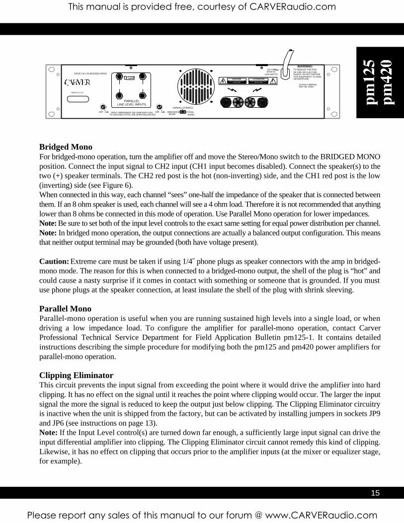
Bridged MonoFor bridged-mono operation, turn the amplifier off and move the Stereo/Mono switch to the BRIDGED MONOposition. Connect the input signal to CH2 input (CH1 input becomes disabled). Connect the speaker(s) to thetwo (+) speaker terminals. The CH2 red post is the hot (non-inverting) side, and the CH1 red post is the low(inverting) side (see Figure 6).When connected in this way, each channel “sees” one-half the impedance of the speaker that is connected betweenthem. If an 8 ohm speaker is used, each channel will see a 4 ohm load. Therefore it is not recommended that anythinglower than 8 ohms be connected in this mode of operation. Use Parallel Mono operation for lower impedances. Note: Be sure to set both of the input level controls to the exact same setting for equal power distribution per channel.Note: In bridged mono operation, the output connections are actually a balanced output configuration. This meansthat neither output terminal may be grounded (both have voltage present).
Caution: Extreme care must be taken if using 1/4˝ phone plugs as speaker connectors with the amp in bridged-mono mode. The reason for this is when connected to a bridged-mono output, the shell of the plug is “hot” andcould cause a nasty surprise if it comes in contact with something or someone that is grounded. If you mustuse phone plugs at the speaker connection, at least insulate the shell of the plug with shrink sleeving.
Parallel MonoParallel-mono operation is useful when you are running sustained high levels into a single load, or whendriving a low impedance load. To configure the amplifier for parallel-mono operation, contact CarverProfessional Technical Service Department for Field Application Bulletin pm125-1. It contains detailedinstructions describing the simple procedure for modifying both the pm125 and pm420 power amplifiers forparallel-mono operation.
Clipping EliminatorThis circuit prevents the input signal from exceeding the point where it would drive the amplifier into hardclipping. It has no effect on the signal until it reaches the point where clipping would occur. The larger the inputsignal the more the signal is reduced to keep the output just below clipping. The Clipping Eliminator circuitryis inactive when the unit is shipped from the factory, but can be activated by installing jumpers in sockets JP9and JP6 (see instructions on page 13). Note: If the Input Level control(s) are turned down far enough, a sufficiently large input signal can drive theinput differential amplifier into clipping. The Clipping Eliminator circuit cannot remedy this kind of clipping.Likewise, it has no effect on clipping that occurs prior to the amplifier inputs (at the mixer or equalizer stage,for example).
This manual is provided free, courtesy of CARVERaudio.com
Please report any sales of this manual to our forum @ www.CARVERaudio.com
CAUTION ATTENTIONRISQUE DE CHOC ELECTRIQUE
NE PAS OUVRIRRISK OF ELECTRIC SHOCK
DO NOT OPEN
TO REDUCE THE RISKOF FIRE OR ELECTRICSHOCK, DO NOT EXPOSETHIS EQUIPMENT TO RAINOR MOISTURE.
WARNING:
120 VAC50-60 Hz
1000 WATTS
CLASS II WIRINGMAY BE USED.
MADE IN U.S.A.
PARALLELLINE LEVEL INPUTS
DUALMONO
NORMAL (STEREO)
BRIDGEDMONO
OFF 0dB
OFF 0dB
INPUT IMPEDANCE 22K OHM EACH LEGTO GROUND (TOTAL 44K OHMS BALANCED)
DRIVE CH 2 IN BRIDGED MONO
of gain (see Figure 4B). For all versions of the amplifiers, the gain remains the same regardless ofwhether the input is balanced or unbalanced.Note: The polarity of the balanced inputs can be reversed by changing four jumpers on the MainBoard near the barrier strip inputs. Cross wire JP103 and JP104 to change the input polarity of CH1and cross wire JP101 and JP102 to change CH2. CAUTION: To avoid the risk of electric shock, refer all internal adjustments to qualified servicep e r s o n n e l .
Input SensitivityThe input sensitivity of the amplifiers are set at the factory to 1.5VR M S for rated output. The input sensitivitycan be changed to 0.775VR M S by adding two jumpers on the Main Amplifier Board. See page 14 of thiso w n e r’s manual for more information.
Output WiringFor Normal Stereo or Dual Mono operation, use the red and black binding posts associated with each channel.These are multi-way binding posts that can be used with standard single or double banana connectors, barewire (up to 8 gauge) or spade lugs.Use heavy-gauge wire for speaker connections. The greater the distance between the amplifier and thespeakers, the larger the diameter the wire should be to minimize power losses across the wire and improve thedamping of the speaker. Wire thickness specifications, or gauges, get larger as the wire gets thinner; thus 14-gauge wire is thicker than 18-gauge wire. Use the following chart as a guide:
Wire Length Gauge of WireUp to 8 ft. 18 gauge
Up to 12 ft. 16 gaugeUp to 20 ft. 14 gaugeUp to 30 ft. 12 gaugeUp to 50 ft. 10 gauge
This will insure that the resistance of the speaker wire is less than 2.5% of 4 ohms, resulting in a transmissionloss of less than 0.1dB. Class II (NEC) wiring can be used.
PolarityLoudspeakers must be connected with consistent polarity for correct phasing between them. Incorrect phasingwill do no physical harm, but frequency response will be affected. The key is to make sure that both speakersconnected to the speaker terminals are hooked up the same way. Connect (–) at the speaker outputs to (–) onthe back of the speaker, and (+) at the speaker outputs to (+) on the back of the speaker.
Dual MonoFor dual-mono operation, turn the amplifier off and move the Stereo/Mono switch to the DUAL M O N Oposition. Connect the input signal to CH2 input (CH1 input becomes disabled). Connect the speakers to theSpeaker Outputs on the amplifier in the same way that you would for normal stereo operation. Both speakeroutputs will carry the signal that is connected to the CH2 input.
14 15
Bridged MonoFor bridged-mono operation, turn the amplifier off and move the Stereo/Mono switch to the BRIDGED MONOposition. Connect the input signal to CH2 input (CH1 input becomes disabled). Connect the speaker(s) to thetwo (+) speaker terminals. The CH2 red post is the hot (non-inverting) side, and the CH1 red post is the low(inverting) side (see Figure 6).When connected in this way, each channel “sees” one-half the impedance of the speaker that is connected betweenthem. If an 8 ohm speaker is used, each channel will see a 4 ohm load. Therefore it is not recommended that anythinglower than 8 ohms be connected in this mode of operation. Use Parallel Mono operation for lower impedances. Note: Be sure to set both of the input level controls to the exact same setting for equal power distribution per channel.Note: In bridged mono operation, the output connections are actually a balanced output configuration. This meansthat neither output terminal may be grounded (both have voltage present).
Caution: Extreme care must be taken if using 1/4˝ phone plugs as speaker connectors with the amp in bridged-mono mode. The reason for this is when connected to a bridged-mono output, the shell of the plug is “hot” andcould cause a nasty surprise if it comes in contact with something or someone that is grounded. If you mustuse phone plugs at the speaker connection, at least insulate the shell of the plug with shrink sleeving.
Parallel MonoParallel-mono operation is useful when you are running sustained high levels into a single load, or whendriving a low impedance load. To configure the amplifier for parallel-mono operation, contact CarverProfessional Technical Service Department for Field Application Bulletin pm125-1. It contains detailedinstructions describing the simple procedure for modifying both the pm125 and pm420 power amplifiers forparallel-mono operation.
Clipping EliminatorThis circuit prevents the input signal from exceeding the point where it would drive the amplifier into hardclipping. It has no effect on the signal until it reaches the point where clipping would occur. The larger the inputsignal the more the signal is reduced to keep the output just below clipping. The Clipping Eliminator circuitryis inactive when the unit is shipped from the factory, but can be activated by installing jumpers in sockets JP9and JP6 (see instructions on page 13). Note: If the Input Level control(s) are turned down far enough, a sufficiently large input signal can drive theinput differential amplifier into clipping. The Clipping Eliminator circuit cannot remedy this kind of clipping.Likewise, it has no effect on clipping that occurs prior to the amplifier inputs (at the mixer or equalizer stage,for example).
This manual is provided free, courtesy of CARVERaudio.com
Please report any sales of this manual to our forum @ www.CARVERaudio.com

C37
P3P4
14
J14P5
P62 1
RP2
J15J16
RP1
J1
U5
U4
ADD THIS JUMPER TOACTIVATE THE CH2
CLIPPING ELIMINATOR
STEREO/MONOSWITCH
CH2 LEVELBYPASS
CH1 LEVELBYPASS
ADD THIS JUMPER TOACTIVATE THE CH1
CLIPPING ELIMINATOR
Servicing InstructionsCAUTION: To reduce the risk of electric shock, do not perform any servicing other than that contained in theOperating Instructions unless you are qualified to do so. Refer all servicing to qualified service personnel.
Stereo/Mono Switch The Stereo/Mono Switch is located on the amplifier’s main circuit board (see Figure 8) and accessible from the backpanel. Leave the switch centered for normal stereo operation, move it to the left for Bridged Mono operation, andmove it to the right for Dual Mono operation.
Level Defeat JumpersThe Level controls can be bypassed by moving the jumpers for CH1 and CH2 (J15 and J16), which are located onthe amplifier’s main circuit board near the level adjustment pots (see Figure 8). This will lock the amplifier into fullgain (as if the Level pots were fully clockwise).
Input Sensitivity ModificationThe input sensitivity of the amplifier is set at the factory to 1.5VRMS for rated output. To increase the sensitivity by6dB to 0.775VRMS, install jumpers JP1 (CH1) and JP11 (CH2). Sockets for these jumpers are located on theamplifier’s main circuit board (see Figure 9).
Input PolarityThe XLR input connectors on the pm125/pm420 are shipped from the factory with pin 2 hot (+), as indicated on the rearpanel. The polarity of the balanced inputs can be reversed by changing four jumpers located on the amplifier’s main circuitboard. Crosswire JP3 and JP4 to change the input polarity of CH1 and crosswire JP101 and JP102 to change CH2 (seeFigure 8).
Clipping Eliminator ActivationThe clipping eliminator circuit can be activated by installing jumpers in sockets JP9 (CH1) and JP6 (CH2) (see Figure 8).
Figure 8
Operating TipsUsing the pm125 /pm420Once the amplifier has been installed and wired into the system, you are ready to use it. Here aresome tips to help you get the most from it.
• Verify that the Stereo/Mono switch has been set to the mode that you want.
• When you power the system up for the first time (out of the carton), it’s a good idea to startwith all of the amplifier level controls turned down, then advance them slowly, one at atime, so that you can confirm that each amplifier channel is operating normally.
• Be sure that the Input Level controls are set sufficiently high to allow the preceding deviceto drive the amplifier to full output. For most installations, this is wide open (fullyclockwise).
• Once you have established settings, it is a good idea to mark them down, either on paper,or on pieces of tape or sticky-dots attached to the amplifier’s panel.
• In bi-amplified (multi-amp) systems, it is a good idea to start with the low-frequencyamplifiers turned off or down, and to check each frequency range from highest to lowestto ensure that each loudspeaker component is operating correctly.
16 1717
This manual is provided free, courtesy of CARVERaudio.com
Please report any sales of this manual to our forum @ www.CARVERaudio.com

C37
P3P4
14
J14P5
P62 1
RP2
J15J16
RP1
J1
U5
U4
ADD THIS JUMPER FOR0.775V INPUT
SENSITIVITY IN CH2
ADD THIS JUMPER FOR0.775V INPUT
SENSITIVITY IN CH2
BACK OF AMPLIFIER
1918
Figure 9
In Case of DifficultyIf you’re having trouble or suspect a problem with the pm125/pm420, try some simple troubleshooting beforecontacting an Authorized Carver Professional Service Center.
No Sound, No PowerThis is usually an indication of a power supply problem, either the power line itself or the amplifier’s power supply.1.pm125/pm420 power is switched off.2.Linecord is disconnected.3.Poor fit between the plug and AC receptacle.4.Power off at AC receptacle (check with tester or lamp).5.The amplifier is plugged into a switched outlet. Verify that the outlet is live.6.The pm125/pm420’s circuit breaker has tripped. Reset the Breaker.
Power On, Low Output or No OutputLow or no output problems are usually signal-source, bad cable or partial output short circuit related. If the items listedbelow check out, then the problem may be internal to the pm125 /pm420.1.The Input Level controls are set too low.2. Move the input connections to another amplifier that you know is working to verify that it is not a source problem.3. Check the speaker connections. Be sure that there are no small strands of wire touching similar strands coming from
the other wire in the cable.4.Make sure the speakers are functioning correctly.5.If you are using bridged-mono mode, ensure that the Stereo /Mono switch is set correctly.6.Use a voltmeter to determine if the power line voltage is dropping excessively when the amplifier is driven hard.
Playback Is Mixed with Hum1.Check or replace the connecting cables.2.Make sure that each screw terminal connection is tight.3. Signal cables may have been routed too closely to AC cables, power transformers, motors or other EMI
inducing device.4. Try connecting another source to the power amplifier inputs. If the hum stops, the problem lies with the
original source component.
DistortionDistortion is usually caused by excessive loss in the input controls (the mixer/equalizer/crossover can’t produceenough output), overdriving resulting in output clipping, or current limiting caused by excessively low loadimpedances.1. Check the setting of the Input Level controls. If set too low, the preceding piece of equipment may not have
sufficient output to overcome the loss.2. Check the speaker connections and verify that all screw connections are tight and that there are no stray strands of
wire to cause short circuits.3. Verify that the total load impedance presented to the amplifier is within the limits described in this manual for the
mode of operation selected.
Care and ServiceAssistance
C a re: Wipe off the pm125/p m 4 2 0 ’s front panel and chassis from time to time with a soft, dry cloth. If you havesomething stubborn to remove, use a mild dish soap or detergent sparingly applied to a soft cloth. Don’t use alcohol,ammonia, or other strong solvents. Service Assistance: We suggest that you read the Limited Warranty completely to fully understand your warranty/service coverage. Please promptly complete and return the Warranty Registration Card. Also be sure to save the salesreceipt in a safe place. It will be necessary for warranty service. If your CARVER Professional product should requireservice, you may contact the CARVER Professional Technical Service Department by calling (503)978-3363 or bywriting to us at the factory address shown below. We will then direct you to the nearest in our national network ofAuthorized Warranty Service Centers or give you detailed instructions on how to return the product to us for promptaction. If you should have questions or comments, please write to the factory address given below. Please include themodel and serial number of your Carver Professional product, your complete address and a daytime phone number.
Carver ProfessionalService Department
P.O. Box 83189Portland, OR 97283
Phone (503)978-3363 • Fax (503)978-3302Carver Professional reserves the right to improve its products at any time. Therefore, specifications are subject to change without notice.
This manual is provided free, courtesy of CARVERaudio.com
Please report any sales of this manual to our forum @ www.CARVERaudio.com

NotesWarranty InformationProfessional Power Amplifiers: 5 years
WHAT IS COVERED:THIS WARRANTY COVERS DEFECTS IN MATERIAL AND WORKMANSHIP ONLY. This limitedWarranty DOES NOT extend to: 1) Damage caused by shipment, 2) damage caused by accident, misuse,
abuse, failure to perform owner maintenance, or operation contrary to the instructions in the Carver Professionalowner’s manual, 3) units on which the serial number has been defaced, modified or removed and 4) damage resultingfrom modification or attempted repair by any other person than authorized by Carver Professional.
WHAT WE WILL PAY FOR:Carver Professional will pay all labor and material expenses for items covered under this Limited Warranty. See thenext section concerning shipping charges.
WHAT YOU MUST DO TO OBTAIN WARRANTY SERVICE:In the event your Carver Professional product requires service, contact your Carver Professional authorized dealer/contractor o r contact Carver Professional (ATTN: Customer Service Dept.) 9300 N. Decatur, Portland, OR 97203 or callthe Customer Service Department directly at (503) 978-3363. You will be directed to an Authorized Carver ProfessionalService Station or receive instructions to ship the unit to the factory. Please save the original shipping carton and packingmaterials in case shipping is required. Please do not ship Parcel Post. Include a complete description of the problem,the associated components and connections, and a copy of the purchase receipt. Initial shipping costs are not paid byCarver Professional. Return shipping costs will be pre-paid if repairs were covered by the scope of this warranty.
YOU MUST RETAIN AND PROVIDE YOUR SALES RECEIPT TO OBTAIN COVERAGE UNDER THIS LIMITED WARRANTY.The warranty Period begins from the date of first consumer purchase from an Authorized Carver Professional Dealer.LIMITATIONS OF IMPLIED WARRANTIES: All implied warranties for merchantability and fitness for a particularpurpose are limited in duration to the warranty period for your product, unless otherwise provided by the state law.
EXCLUSION OF CERTAIN DAMAGES:In no event shall Carver Professional be liable for property or any other incidental or coincidental damages which mayresult from the failure of this product. If your Carver Professional product proves defective in material orworkmanship, the liability of Carver Professional shall be limited to the repair or replacement, at the option of CarverProfessional, of any defective part.
STATE LAWS MAY DIFFER:Some states do not allow limitations on how long an implied warranty lasts and/or do not allow the exclusion orlimitation of incidental or consequential damages, so the above limitations may not apply to you. This warranty givesyou specific legal rights, and you may have other rights which vary from state to state.
OTHER IMPORTANT PROVISIONS:Carver Professional reserves the right to make changes in design and improvements to its products without theresponsibility of installing such changes to improvements on products previously sold by Carver Professional. Wesuggest that you attach your purchase receipt to this Warranty and keep both documents in a safe place. Thank youfor your choice of a Carver Professional Amplifier.
NOTE:The following warranty is exclusive to the United States and its possessions and territories. Please see your CarverProfessional dealer or distributor for the correct warranty information in your area or locale.
20 21
This manual is provided free, courtesy of CARVERaudio.com
Please report any sales of this manual to our forum @ www.CARVERaudio.com

DECLARATION OF CONFORMITY
We PHOENIX GOLD INTERNATIONAL, INC.(supplier’s name)
9300 N. DECATUR, PORTLAND, OR 97203 USA(address)
declare under our sole responsibility that the productpm125/420
(name, type or model, lot, batch or serial number, possibly sources and numbers of items)to which this declaration relates is in conformity with the following standard(s) or other normative document(s)
EN55013, EN55020, EN60065(title and /or number and date if issue of the standard(s) or other normative document(s)
(if applicable) following the provisions of89/336/EEC/73/23 EEC
DirectivePORTLAND,OR USAApril 25, 1997
(Place and date of issue)
(name and signature or equivalentmarking of authorized person)
A Division Of Phoenix Gold International, Inc.
Part #8100.0088B
5Year Warranty
18 0DAYPerformance
Guarantee Made In America
9300 North Decatur Portland OR 97203 Tel: 503.288.2008 Fax: 503.978.3302
p m 1 2 5 / p m 4 2 0Professional Stereo Power Amplifier
This manual is provided free, courtesy of CARVERaudio.com
Please report any sales of this manual to our forum @ www.CARVERaudio.com