carson dorn, inc
TRANSCRIPT

City and Borough of Juneau Juneau Douglas Wastewater Treatment Plant
Facility Maintenance Evaluation Report
MAY 21, 2014
C a r s o n D o r n , In c .

JUNEAU DOUGLAS WASTEWATER TREATMENT PLANT
FACILITY MAINTENANCE EVALUATION REPORT
712 West 12th Street Juneau, Alaska 99801
Telephone: (907) 586-4447 Fax: (907) 586-5917
MAY 21, 2014
C a r s o n D o r n , In c .

TABLE OF CONTENTS
FOR THE
JUNEAU DOUGLAS WASTEWATER TREATMENT PLANT FACILITY MAINTENANCE EVALUATION REPORT
1 - INTRODUCTION .................................................................................................. 1-1 2 - REPLACED EQUIPMENT ...................................................................................... 2-1 3 - EQUIPMENT LIST, MAINTENANCE EVALUATION, CONDITION ASSESSMENT, AGE AND ESTIMATED USEFUL LIFE ........................................................................ 3-1 TABLE 1 JDWWTP Equipment List, Age, and Estimated Useful Life TREATMENT EQUIPMENT CONDITION ASSESSMENTS 3.1 Headworks 3.1.1 Grit Chain and Flight 3.1.2 Grit Collector, Circular 3.1.3 Auger Monster 3.2 Control Building 3.2.1 Auxiliary Pumps No. 1 and No. 2 3.2.2 Antero Maintenance Data Management System 3.3 Clarifiers 3.3.1 Clarifiers No. 1 and No. 2 3.3.2 Return Activated Sludge Pumps No. 1 and No. 2 3.3.3 Waste Activated Sludge Pumps No. 1 and No. 2 3.4 Aeration Basins 3.4.1 Aeration Basin Aerators 1, 2, 3, and 4 3.5 UV System 3.5.1 UV System Bank A and Bank B 3.6 Sludge Digester 3.6.1 Sludge Digester Aerator 3.7 Belt Filter Press 3.7.1 Belt Filter Press 3.7.2 Belt Filter Press Booster Pump 3.7.3 Belt Filter Press Hydraulic Pressure Pump

TABLE OF CONTENTS
FOR THE
JUNEAU DOUGLAS WASTEWATER TREATMENT PLANT FACILITY MAINTENANCE EVALUATION REPORT
3.8 Sludge Feed System 3.8.1 Sludge Feed Pump 3.8.2 Sludge Grinder 3.8.3 Polymer Mixer No. 1 and No. 2 3.8.4 Polymer Feed Pump 3.9 Wastewater Return Sump Pumps 3.9.1 Wastewater Return Sump Pumps No. 1 and No. 2 3.10 Utility Water Pumps 3.10.1 Utility Water Pumps No. 1 and No. 2 4 - EQUIPMENT MAINTENANCE SCHEDULE, STAFFING AND COSTS .................. 4-1 TABLE 2 JDWWTP Maintenance Schedule, Staffing and Costs 5 – FIVE YEAR CAPITAL REPLACEMENT CHART ................................................... 5-1 TABLE 3 Estimated 5-Year Capital Replacement Fund

1- INTRODUCTION The Juneau Douglas Wastewater Treatment Plant (JDWWTP) is located about 1 mile
south of town on the old mine tailings rock dump. It was designed and constructed in
1973 with the capacity to treat average daily flows of about 2.76 million gallons per day
and peak daily flows of about 7.23 million gallons per day. It is an activated sludge
system with grit removal in the headworks, two aeration basins, two secondary clarifiers,
a ultraviolet (UV) light disinfection system and a disgester for treating and storing sludge
prior to dewatering it with a belt filter press. The JDWWTP Site Plan Figure shows the
JDWWTP Site and the location of the treatment units on the site..
With the plant nearing 40 years of age there is increasing interest in operation,
maintenance and replacement costs for the plant.
This report is a Facility Maintenance Evaluation Report that contains the following:
Chapter 2 – Replaced Equipment
This chapter contains a summary of the equipment at the JDWWTP that has been
replaced since the treatment plant was first constructed. It indicates that the City and
Borough of Juneau (CBJ) has responsibly responded to issues of aging equipment over
the years and has regularly replaced equipment that no longer performs as intended.
Chapter 3 – Equipment List, Maintenance Evaluation, Condition Assessment, Age and Estimated Useful Life
This chapter contains a condition assessment and maintenance evaluation for each of the
major wastewater treatment equipment items at the JDWWTP. It also contains a more
inclusive table listing equipment at the JDWWTP, its age and an estimate of its
remaining useful life.
Carson Dorn Inc. Page 1-1

JDWWTP Facility Maintenance Evaluation Report
Chapter 4 – Equipment Maintenance Schedule, Staffing and Costs
The chapter contains a summary of the maintenance activities, their required frequency,
estimated labor hours to complete each activity and the estimated costs for the tasks.
Chapter 5 – Five Year Capital Replacement Chart
The Five Year Capital Replacement Chart considers equipment with an estimated
remaining useful life of 15 years or less and then estimates the annual costs based on the
equipment failing within the next 15 years.
Carson Dorn Inc. Page 1-2


2 – REPLACED EQUIPMENT The Juneau Douglas Wastewater Treatment Plant (JDWWTP) was designed and
constructed in 1973 so many parts of the plant are over 40 years old. Assets at a waste
water treatment plant can have estimated useful lives on the order of 30 to 40 years. So
as expected, CBJ has begun the process of replacing some of the equipment at the
JDWWTP that reached the end of its useful life and was no longer performing as
intended. With equipment that has not been replaced and which regularly receives
routine maintenance the “useful life” will keep being extended until the equipment item
no longer performs as intended or becomes increasingly inefficient to operate.
Original equipment items that have been replaced at the JDWWTP over the years include
the following:
• Grit Removal Chain and Flight
• Control Building Auxiliary Pump No. 1
• Control Building Auxiliary Pump No. 2
• Clarifier No. 1 Drive, Sweep, Catwalk and Support Column
• Clarifier No. 2 Drive, Sweep, Catwalk and Support Column
• Return Activated Sludge Pump No. 1
• Return Activated Sludge Pump No. 2
• Belt Filter Press Water Booster Pump Unit
• Utility Water Booster Pump Drive Motor
• Wastewater Return Sump Pump No. 1 (currently out of service but soon to be
replaced)
It appears that CBJ has responsibly responded to issues of aging equipment over the years
and regularly replaced equipment that no longer performed as intended.
Carson Dorn Inc. Page 2-1

3 – EQUIPMENT LIST, MAINTENANCE EVALUATION, CONDITION ASSESSMENT, AGE
AND ESTIMATED USEFUL LIFE All equipment will eventually reach the end of its useful life. Some equipment will reach
this point sooner than others. For example a pump will wear out sooner if it is used more
and will last longer if it is used less. The actual age of the pump is not as important as the
amount of work the pump has done. There are many factors that will affect how much
remaining life a given piece of equipment has. Factors such as poor installation,
defective materials, corrosive environment and poor maintenance will shorten the useful
life of a piece of equipment, whereas good installation, proper routine and preventative
maintenance and a non-corrosive environment will tend to lengthen an equipment items
life. Taking these factors into account and the age of piece of equipment, subjective
opinions can be developed with regards to the estimated useful age of a piece of
equipment.
The following Table 1 JDWWTP Equipment List, Age and Estimated Useful Life is a
summary of the treatment equipment units and other equipment at the JDWWTP along
with its age and estimated remaining useful life.
Equipment condition assessments for each of the following treatment are found after
Table 1.
3.1 Headworks 3.1.1 Grit Chain and Flight 3.1.2 Grit Collector, Circular 3.1.3 Auger Monster 3.2 Control Building 3.2.1 Auxiliary Pumps No. 1 and No. 2 3.2.2 Antero Maintenance Data Management System Carson Dorn Inc. Page 3-1

JDWWTP Facility Maintenance Evaluation Report 3.3 Clarifiers 3.3.1 Clarifiers No. 1 and No. 2 3.3.2 Return Activated Sludge Pumps No. 1 and No. 2 3.3.3 Waste Activated Sludge Pumps No. 1 and No. 2 3.4 Aeration Basins 3.4.1 Aeration Basin Aerators 1, 2, 3, and 4 3.5 UV System 3.5.1 UV System Bank A and Bank B 3.6 Sludge Digester 3.6.1 Sludge Digester Aerator 3.7 Belt Filter Press 3.7.1 Belt Filter Press 3.7.2 Belt Filter Press Booster Pump 3.7.3 Belt Filter Press Hydraulic Pressure Pump 3.8 Sludge Feed System 3.8.1 Sludge Feed Pump 3.8.2 Sludge Grinder 3.8.3 Polymer Mixer No. 1 and No. 2 3.8.4 Polymer Feed Pump 3.9 Wastewater Return Sump Pumps 3.9.1 Wastewater Return Sump Pumps No. 1 and No. 2 3.10 Utility Water Pumps 3.10.1 Utility Water Pumps No. 1 and No. 2
Carson Dorn Inc. Page 1-2

TABLE 1JDWWTP EQUIPMENT LIST, AGE AND ESTIMATED USEFUL LIFE
1 of 3
Year Constructed /
Replaced Age (yrs)Estimated Useful
Life (yrs)HEADWORKS
Grit Chain and Flight 2013 1 30-40Grit Chain Drive Motor and Gear Reducer 1973 41 5-15Grit Collector, Circular 1973 41 5-15Auger Monster 2010 4 30-40
CONTROL BUILDINGAuxiliary Pump No. 1 2012 2 30-40Auxiliary Pump No. 2 2012 2 30-40Antero Maintenance Software 1991 23 10-20
CLARIFIERSClarifier No 1 2006 8 20-30Clarifier No. 2 2006 8 20-30Return Activated Sludge Pump No. 1 2009 5 20-30Return Activated Sludge Pump No. 2 2009 5 20-30Waste Activated Sludge Pump No. 1 1973 41 5-15Waste Activated Sludge Pump No. 2 1973 41 5-15
AERATION BASINSAerator No.1, Basin 1 Channel End 1973 41 5-15Aerator No. 2, Basin 1 Mountain End 1973 41 5-15Aerator No. 3, Basin 2 Channel End 1973 41 5-15Aerator No. 4, Basin 2 Mountain End 1973 41 5-15
UV DISINFECTIONUV System Bank A 1999 15 20-30UV System Bank B 1999 15 20-30
SLUDGE DIGESTERAerator No. 5, Sludge Digester 1973 41 5-15
BELT FILTER PRESSBelt Filter Press 1990 24 10-20Belt Filter Press Booster Pump 1990 24 10-20Belt Filter Press Hydraulic Pressure Pump 1990 24 10-20
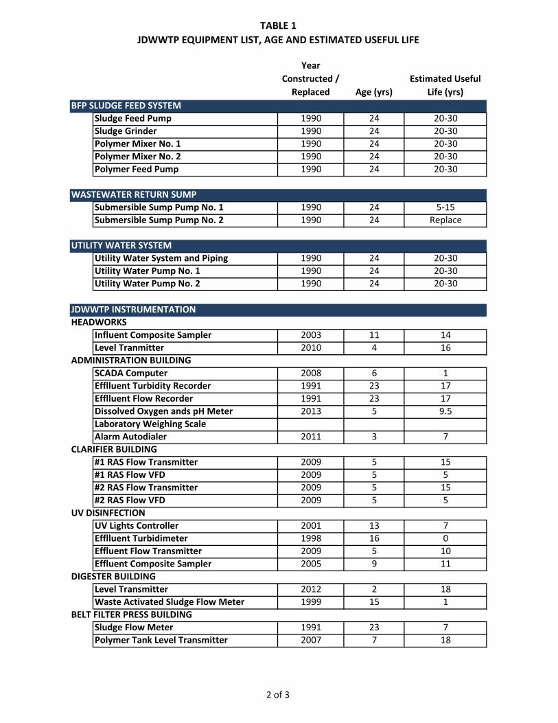
TABLE 1JDWWTP EQUIPMENT LIST, AGE AND ESTIMATED USEFUL LIFE
2 of 3
Year Constructed /
Replaced Age (yrs)Estimated Useful
Life (yrs)BFP SLUDGE FEED SYSTEM
Sludge Feed Pump 1990 24 20-30Sludge Grinder 1990 24 20-30Polymer Mixer No. 1 1990 24 20-30Polymer Mixer No. 2 1990 24 20-30Polymer Feed Pump 1990 24 20-30
WASTEWATER RETURN SUMPSubmersible Sump Pump No. 1 1990 24 5-15Submersible Sump Pump No. 2 1990 24 Replace
UTILITY WATER SYSTEMUtility Water System and Piping 1990 24 20-30Utility Water Pump No. 1 1990 24 20-30Utility Water Pump No. 2 1990 24 20-30
JDWWTP INSTRUMENTATIONHEADWORKS
Influent Composite Sampler 2003 11 14Level Tranmitter 2010 4 16
ADMINISTRATION BUILDINGSCADA Computer 2008 6 1Efflluent Turbidity Recorder 1991 23 17Efflluent Flow Recorder 1991 23 17Dissolved Oxygen ands pH Meter 2013 5 9.5Laboratory Weighing ScaleAlarm Autodialer 2011 3 7
CLARIFIER BUILDING#1 RAS Flow Transmitter 2009 5 15#1 RAS Flow VFD 2009 5 5#2 RAS Flow Transmitter 2009 5 15#2 RAS Flow VFD 2009 5 5
UV DISINFECTIONUV Lights Controller 2001 13 7Efflluent Turbidimeter 1998 16 0Effluent Flow Transmitter 2009 5 10Effluent Composite Sampler 2005 9 11
DIGESTER BUILDINGLevel Transmitter 2012 2 18Waste Activated Sludge Flow Meter 1999 15 1
BELT FILTER PRESS BUILDINGSludge Flow Meter 1991 23 7Polymer Tank Level Transmitter 2007 7 18
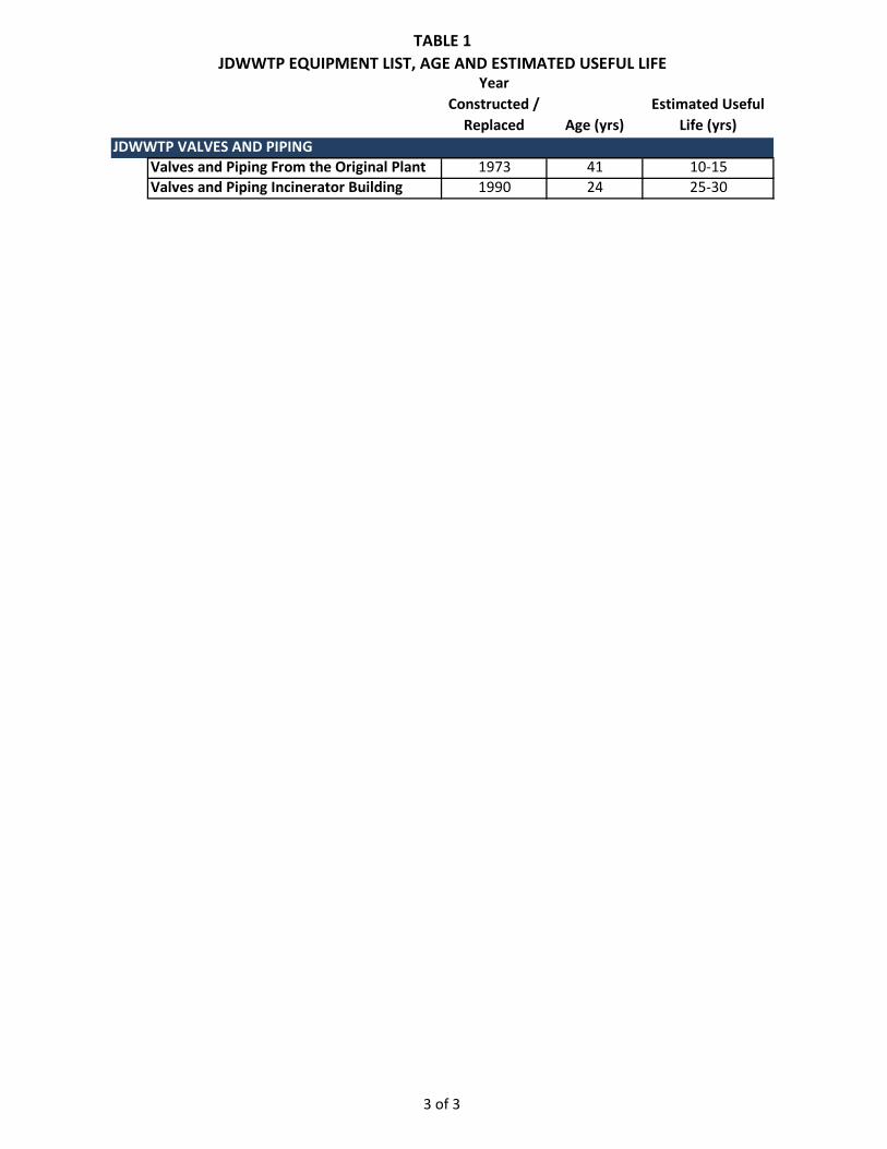
TABLE 1JDWWTP EQUIPMENT LIST, AGE AND ESTIMATED USEFUL LIFE
3 of 3
Year Constructed /
Replaced Age (yrs)Estimated Useful
Life (yrs)JDWWTP VALVES AND PIPING
Valves and Piping From the Original Plant 1973 41 10-15Valves and Piping Incinerator Building 1990 24 25-30

3.1 HEADWORKS
The primary purpose of the headworks area is removal of grit and other debris from the influent. The grit chain and flight and the circular grit collector are old but with the repairs that have been made over the years appear to be operating with no obvious problems. The auger monster screening system was installed in 2010 and also appears to be operating with no obvious problems.
HEADWORKS BUILDING
This building has a wood rafter roof and the roof doesn't appear to have any significant issues. The concrete foundation has a large "crack" that showed up shortly after construction in the 70's. Repairs have been made to the crack and it appears to be performing satisfactorily and there are no signs of leakage. CBJ regularly inspects the crack to make sure there are no leakage issues.
The following treatment equipment items are evaluated in the following pages:
3.1.1 GRIT CHAIN AND FLIGHT
The grit chain and flight conveys grit that has settled in the circular grit removal chamber up a concrete conveyor trough and deposits the grit into a dumpster for subsequent disposal.
3.1.2 GRIT COLLECTOR, CIRCULAR
The circular grit chamber provides a quiescent area for grit in the waste water influent to settle. The circular grit collector has a rake arm that slowly rotates in the collector and moves settled grit to a steeply inclined concrete slope where the grit slides down to the trough for the chain and flight where it is removed.
3.1.3 AUGER MONSTER
The auger monster is an inclined screen that removes debris such as rags, strings and other materials that may form large rope mats in the treatment process. The debris is removed by the screens and the auger conveys the debris to a dumpster for subsequent disposal.

GRIT CHAIN AND FLIGHT
JDWWTP HEADWORKS
SITE PLAN
GRIT COLLECTOR, CIRCULAR
AUGER MONSTER
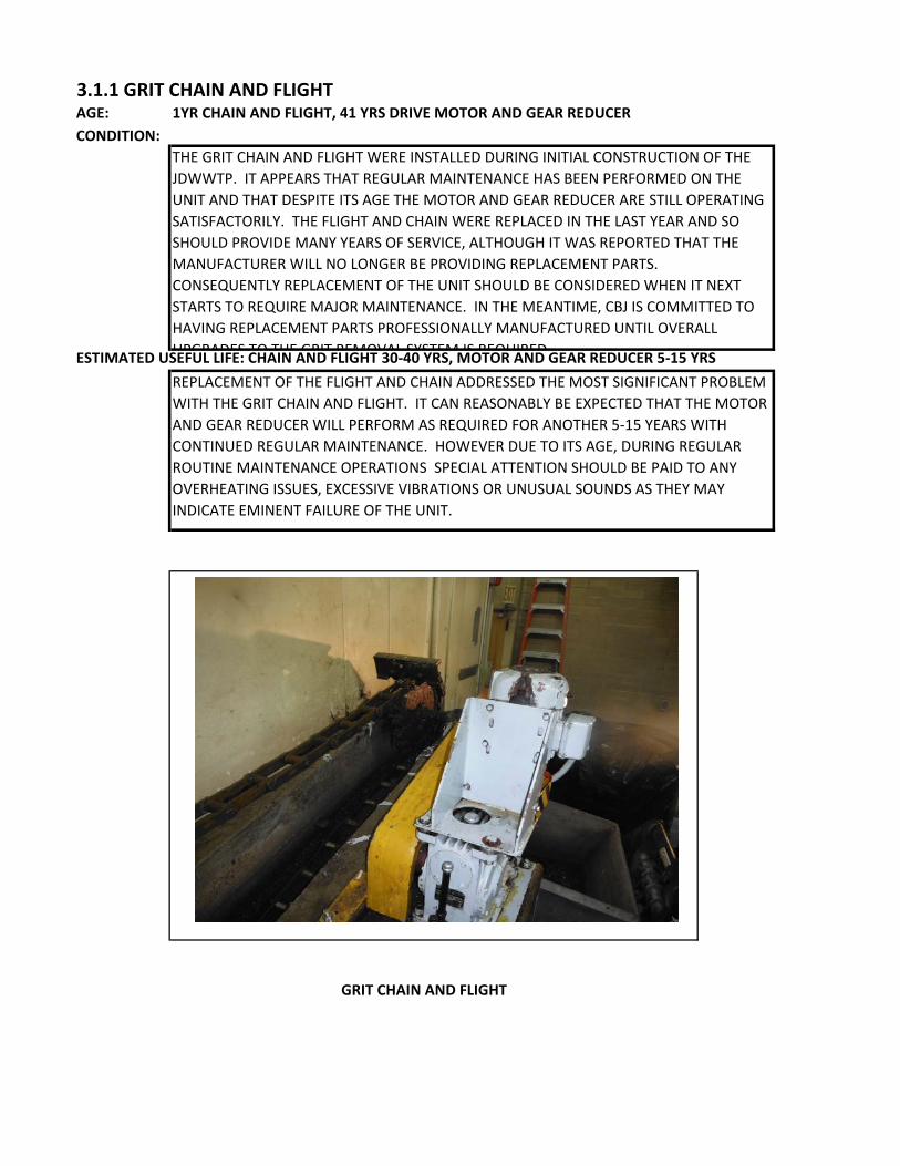
3.1.1 GRIT CHAIN AND FLIGHTAGE: 1YR CHAIN AND FLIGHT, 41 YRS DRIVE MOTOR AND GEAR REDUCERCONDITION:
ESTIMATED USEFUL LIFE: CHAIN AND FLIGHT 30-40 YRS, MOTOR AND GEAR REDUCER 5-15 YRS
THE GRIT CHAIN AND FLIGHT WERE INSTALLED DURING INITIAL CONSTRUCTION OF THE JDWWTP. IT APPEARS THAT REGULAR MAINTENANCE HAS BEEN PERFORMED ON THE UNIT AND THAT DESPITE ITS AGE THE MOTOR AND GEAR REDUCER ARE STILL OPERATING SATISFACTORILY. THE FLIGHT AND CHAIN WERE REPLACED IN THE LAST YEAR AND SO SHOULD PROVIDE MANY YEARS OF SERVICE, ALTHOUGH IT WAS REPORTED THAT THE MANUFACTURER WILL NO LONGER BE PROVIDING REPLACEMENT PARTS. CONSEQUENTLY REPLACEMENT OF THE UNIT SHOULD BE CONSIDERED WHEN IT NEXT STARTS TO REQUIRE MAJOR MAINTENANCE. IN THE MEANTIME, CBJ IS COMMITTED TO HAVING REPLACEMENT PARTS PROFESSIONALLY MANUFACTURED UNTIL OVERALL UPGRADES TO THE GRIT REMOVAL SYSTEM IS REQUIRED
REPLACEMENT OF THE FLIGHT AND CHAIN ADDRESSED THE MOST SIGNIFICANT PROBLEM WITH THE GRIT CHAIN AND FLIGHT. IT CAN REASONABLY BE EXPECTED THAT THE MOTOR AND GEAR REDUCER WILL PERFORM AS REQUIRED FOR ANOTHER 5-15 YEARS WITH CONTINUED REGULAR MAINTENANCE. HOWEVER DUE TO ITS AGE, DURING REGULAR ROUTINE MAINTENANCE OPERATIONS SPECIAL ATTENTION SHOULD BE PAID TO ANY OVERHEATING ISSUES, EXCESSIVE VIBRATIONS OR UNUSUAL SOUNDS AS THEY MAY INDICATE EMINENT FAILURE OF THE UNIT.
GRIT CHAIN AND FLIGHT

3.1.2 GRIT COLLECTOR, CIRCULARAGE: 41 yrsCONDITION:
ESTIMATED USEFUL LIFE: 5-15 YEARS
THE GRIT COLLECTOR WAS INSTALLED DURING INITIAL CONSTRUCTION OF THE JDWWTP. IT APPEARS THAT REGULAR OIL CHANGES AND GREASING HAVE BEEN PERFORMED ON THE UNIT. DESPITE ITS AGE THE MOTOR AND GEAR REDUCER ARE STILL OPERATING SATISFACTORILY.
OUTSIDE OF SOME COSMETIC ISSUES ON THE MOTOR AND GEAR REDUCER (RUST), THERE ARE NO OBVIOUS MAINTENANCE ISSUES WITH THE GRIT COLLECTOR. IT CAN REASONABLY BE EXPECTED THAT THE UNIT WILL PERFORM AS REQUIRED FOR ANOTHER 5-15 YEARS WITH CONTINUED REGULAR MAINTENANCE. HOWEVER DUE TO ITS AGE, DURING REGULAR ROUTINE MAINTENANCE OPERATIONS SPECIAL ATTENTION SHOULD BE PAID TO ANY OVERHEATING ISSUES, EXCESSIVE VIBRATIONS OR UNUSUAL SOUNDS AS THEY MAY INDICATE EMINENT FAILURE OF THE UNIT.
GRIT COLLECTOR, CIRCULAR

3.1.3 AUGER MONSTERAGE: 4CONDITION:
ESTIMATED USEFUL LIFE: 30-40 YEARS
THE AUGER MONSTER SCREENING SYSTEM WAS INSTALLED TO REMOVE DEBRIS THAT WAS FORMING BALLS OF STRING AND OTHER DEBRIS THROUGHOUT THE PLANT. THE UNIT IS RELATIVELY NEW BUT IS ALREADY SHOWING SIGNS OF THE CORROSIVE ENVIRONMENT EVIDENT IN THE HEADWORKS AREA. THE MAINTENANCE WORK ORDERS FOR THE AUGER MONSTER HAVE BEEN UPDATED TO INCLUDE ALL THE RECOMMENDED SERVICE SUCH AS INSPECTING AND CLEANING THE SPRAY WASH AND AUGER, AND CHECKING THE AUGER DRIVE ASSEMBLY.
OUTSIDE OF SOME COSMETIC ISSUES ON THE MOTOR AND GEAR REDUCER (RUST), THERE ARE NO OBVIOUS MAINTENANCE ISSUES WITH THE AUGER. IT CAN REASONABLY BE EXPECTED THAT THE UNIT WILL PERFORM AS REQUIRED FOR ANOTHER 30-40 YEARS WITH CONTINUED REGULAR MAINTENANCE.
AUGER MONSTER

3.2 CONTROL BUILDING
The Control Building houses the main office (including the Antero equipment maintenance computers and software), motor control center, laboratory, break room, a storage garage and the auxiliary pumps. The auxiliary pumps in the Control Building were replaced in 2012 and so are expected to perform for many years. The Antero facility maintenance software system is outdated and CBJ is evaluating more robust alternatives for replacing the management system. In the meantime the Antero software appears to be performing satisfactorily and will continue to be used to generate maintenance work orders for the equipment at the JDWWTP until it is replaced.
CONTROL BUILDING
This building has a brick exterior and metal beam and wood rafter roof with hot tar waterproofing. The Control Building and its roof do not appear to have any significant issues.
Each of the following treatment equipment is evaluated in the following pages:
3.2.1 AUXILIARY PUMPS NO. 1 AND NO.2
The Auxiliary Pumps are used for variety of purposes including draining the aeration basins, pond supernatant return, waste sludge and scum pumping. They were replaced with new pumps in 2012 and are performing satisfactorily.
3.2.2 ANTEROR MAINTENANCE DATA MANAGEMENT SYSTEM
The Antero maintenance management system was installed in 1991 and consequently is old and outdated. CBJ is considering alternative maintenance management software that may provide additional features for equipment maintenance and management. Until such time as new software is purchased and installed, CBJ will continue to use the Antero system for generating maintenance work orders for equipment at the JDWWTP.

JDWWTP CONTROL BUILDING
SITE PLAN
ANTERO MAINTENANCE DATA MANAGEMENT
SYSTEM AUXILIARY PUMPS NO. 1 AND NO. 2

3.2.1 AUXILIARY PUMPS NO. 1 AND NO. 2AGE: 2 yrsCONDITION:
ESTIMATED USEFUL LIFE: 30-40 YEARS
THE AUXILIARY PUMPS WERE REPLACED WITH NEW PUMPS APPROXIMATELY 2 YEARS AGO AND SO ARE IN RELATIVELY NEW CONDITION. REQUIRED MAINTENANCE IS BEING PERFORMED ON THEM ON A REGULAR BASIS.
THE PUMPS ARE ESSENTIALLY NEW AND WITH PROPER REGULAR MAINTENANCE CAN BE EXPECTED TO LAST BETWEEN 30 TO 40 YEARS.
AUXILIARY PUMPS NO. 1 AND NO. 2

3.2.2 ANTERO MAINTENANCE DATA MANAGEMENT SYSTEMAGE: 23 yrsCONDITION:
ESTIMATED USEFUL LIFE: 3-5 YEARS
CBJ currently uses version 4.10.1292 (a 2008 version) of the Antero maintenance software tracking program, a product by AllMax Software. The most current version of Antero is 6.12.0030 (a 2014 version), more than a dozen revisions newer. While AllMax does support the antiquated CBJ version of Antero, it is suspected that such support will soon dissipate. Additionally, as Antero is primarily a maintenance software program, it does not incorporate many components of a full-featured asset management/equipment replacement program needed to effectively run CBJ Wastewater Utility (WWU) operations. Further, Antero has no GIS connectivity or internet based components which would enable the use of mobile devices and/or field real-time updates/inputting throughout the facilities. As such, CBJ WWU is currently examining more robust software alternatives to implement for system-wide asset management and maintenance programming.
The Antero maintenance software system is outdated and CBJ is evaluating more robust software alternatives. As such the remaining useful life is estimated to only be 3 - 5 years.

3.3 CLARIFIERS
The clarifier’s main purpose is to allow activated sludge to settle in the clarifiers and clean supernatant to be discharged from the plant as treated effluent. The settled activated sludge is either returned to the aeration basins to ensure adequate concentrations of microorganisms are maintained in the aeration basins for treatment of the waste water or the settled sludge is wasted to the sludge digester for treatment and disposal. The clarifiers were replaced in 2006 and there are no obvious problems with the clarifier operation. The return activated sludge pumps were replaced in 2009 and there are no obvious problems with the return activated sludge operation. The waste activated sludge pumps are still the original pumps and have been maintained since 1973. There does not appear to be any operating problems with the waste activated sludge pumps, but due to their age they should be carefully monitored.
CLARIFIER BUILDING
The Clarifier Building is showing signs of significant corrosion and should be considered for replacement. However, there is nothing in the building that appears to require immediate attention. Although it does not affect plant operation some of the doors are showing some aging and should be considered for replacement.
The following treatment equipment items are evaluated in the following pages:
3.3.1 CLARIFIERS NO. 1 AND NO. 2
The clarifiers receive mixed liquor from the aeration basins containing significant concentrations of suspended solids and microorganisms. The clarifiers allow the suspended solids and microorganisms to settle into a sludge blanket on the bottom of the clarifier and clear supernatant is allowed to flow over an effluent weir for final disinfection and discharge from the treatment facility.
3.3.2 RETURN ACTIVATED SLUDGE PUMPS NO. 1 AND NO. 2
The return activated sludge pumps are used to return microorganisms from the clarifiers to the aeration basins to maintain the necessary quantity of microorganisms needed to treat the sewage influent.
3.3.3 WASTE ACTIVATED SLUDGE PUMPS NO. 1 AND NO. 2
The waste activated sludge pumps are used to remove excess microorganisms from the clarifiers to the sludge digester when the quantity of microorganisms in the aeration basins becomes greater than the desired amount.

JDWWTP CLARIFIERS SITE PLAN
CLARIFIER NO. 1
CLARIFIER NO. 2
RETURN ACTIVATED SLUDGE PUMP NO. 1 RETURN ACTIVATED
SLUDGE PUMP NO. 2
WASTE ACTIVATED SLUDGE PUMP NO. 1
WASTE ACTIVATED SLUDGE PUMP NO. 2

3.3.1 CLARIFIER NO 1. AND NO. 2AGE: 8 YRSCONDITION:
ESTIMATED USEFUL LIFE: 20-30 YEARS
THE CLARIFIER UNITS ARE RELATIVELY NEW HAVING BEEN REPLACED ABOUT 8 YEARS AGO. THEY ARE ALREADY SHOWING SIGNS OF THE CORROSIVE ENVIRONMENT EVIDENT IN THE CLAFIFIER AREA WITH RUST ON THE DRIVE UNITS. THE CLARIFIERS ARE BEING REGULARLY MAINTAINED.
THERE ARE NO OBVIOUS MAINTENANCE ISSUES WITH THE CLARIFIERS AND IT CAN REASONABLY BE EXPECTED THAT THE UNITS WILL PERFORM AS REQUIRED FOR ANOTHER 20-30 YEARS WITH REGULAR MAINTENANCE.
TYPICAL CLARIFIER DRIVE MECHANISM

3.3.2 RETURN ACTIVATED SLUDGE PUMPS NO. 1 AND NO. 2AGE: 5 YRSCONDITION:
ESTIMATED USEFUL LIFE: 20-30 YEARS
THE RETURN ACTIVATED SLUDGE PUMPS ARE RELATIVELY NEW HAVING BEEN REPLACED ABOUT 5 YEARS AGO. WHILE THE SUBMERSIBLE PUMPS WERE NOT VISIBLE, RECORDS SHOW THEY ARE BEING PULLED AND INSPECTED ON AN ANNUAL BASIS.
THERE ARE NO OBVIOUS MAINTENANCE ISSUES WITH THE RAS PUMPS AND IT CAN REASONABLY BE EXPECTED THAT THE UNITS WILL PERFORM AS REQUIRED FOR ANOTHER 20-30 YEARS WITH REGULAR MAINTENANCE. DISCHARGE PIPING FROM THE RAS PUMPS APPEARS OLD AND SHOULD BE REGULARLY MONITORED FOR LEAKS.
RETURN ACTIVATED SLUDGE SUBMERSIBLE PUMP SUMP

3.3.3 WASTE ACTIVATED SLUDGE PUMPS NO. 1 AND NO. 2AGE: 41 YRSCONDITION:
ESTIMATED USEFUL LIFE: 5-15 YEARS
THE WAS PUMPS WERE INSTALLED DURING INITIAL CONSTRUCTION OF THE JDWWTP. IT APPEARS THAT REGULAR GREASING HAS BEEN PERFORMED ON THE UNIT. DESPITE ITS AGE THE PUMPS ARE STILL OPERATING SATISFACTORILY.
OUTSIDE OF COSMETIC ISSUES ON THE MOTOR, THERE ARE NO OBVIOUS MAINTENANCE ISSUES WITH THE WAS PUMPS. IT CAN REASONABLY BE EXPECTED THAT THE PUMPS WILL PERFORM AS REQUIRED FOR ANOTHER 5-15 YEARS WITH CONTINUED REGULAR MAINTENANCE. HOWEVER DUE TO THEIR AGE, DURING REGULAR ROUTINE MAINTENANCE OPERATIONS SPECIAL ATTENTION SHOULD BE PAID TO ANY OVERHEATING ISSUES, EXCESSIVE VIBRATIONS OR UNUSUAL SOUNDS AS THEY MAY INDICATE EMINENT FAILURE OF THE UNIT.
WASTE ACTIVATED SLUDGE PUMP MOTOR
3.4 AERATION BASINS
In the aeration basins the raw sewage is mixed with microorganisms resident in the basin and returned from the clarifiers. Under proper conditions of mixing and aeration the microorganisms use the organic material in the raw influent for reproduction and respiration. The microorganism bodies and the material that adheres to them are heavier than water and so will sink in the clarifiers. This sinking material is the activated sludge blanket in the clarifier.
The mechanical surface aerators in the aeration basins have been maintained since 1973 but they have not been replaced. There does not appear to be any operating problems with the aerators, but due to their age and the corrosive environment, the platforms for their motors have significant deterioration. CBJ is replacing the platforms and access walkways to the surface aerators in the aeration basins.
AERATION BASIN BUILDINGS
The Aeration Basin Buildings are showing signs of significant corrosion and should be considered for replacement. However despite their appearance, there is nothing in the buildings that appear to require immediate attention. The concrete foundations appear to be in good condition however the concrete stairs have exposed rebar and should be replaced for operator safety.
The following treatment equipment items are evaluated in the following pages:
3.4.1 AERATION BASIN AERATORS 1, 2, 3, AND 4
The aeration basin aerators consist of large electric motor driven mixers on floats. These aerators keep the oxygen level in the aeration basin high enough to encourage the growth of aerobic microorganisms and ensure mixing within the basin to reduce dead spots where oxygen levels may be low or where solids may settle out.

JDWWTP AERATION BASIN SITE PLAN
AERATOR NO. 1
AERATOR NO. 2
AERATOR NO. 4
AERATOR NO. 3

3.4.1 AERATION BASIN AERATORS 1, 2, 3, AND 4AGE: 41CONDITION:
ESTIMATED USEFUL LIFE: 5-15 YEARS
THE MECHANICAL SURFACE AERATORS HAVE BEEN IN OPERATION FOR OVER 40 YEARS IN A HARSH ENVIRONMENT. MAINTENANCE HAS HISTORICALLY BEEN PERFORMED ON THE AERATORS AND THEY APPEAR TO BE OPERATING SATISFACTORILY. HOWEVER ACCESS TO THE AERATORS HAS BEEN RESTRICTED IN RECENT YEARS DUE TO THE CONDITION OF THE METAL AERATOR PLATFORMS. DUE TO THE LIMITED ACCESS REGULAR ROUTINE MAINTENANCE OPERATIONS ARE NOT BEING PERFORMED. RECOMMEND REPAIRING THE WALKWAYS AS SOON AS POSSIBLE TO ALLOW ACCESS TO THE AERATORS FOR MAINTENANCE. CONSTRUCTION PLANS ARE BEING DEVELOPED FOR THE REPAIR/REPLACEMENT OF THE CATWALKS AND PLATFORMS. REPAIRS ARE SCHEDULED TO BE COMPLETED BY FALL 2014.
THERE ARE NO OBVIOUS MAINTENANCE ISSUES WITH THE AERATORS. IT CAN REASONABLY BE EXPECTED THAT THE UNITS WILL PERFORM AS REQUIRED FOR ANOTHER 5-15 YEARS WITH REGULAR MAINTENANCE WHICH MAKES REPAIRING THE WALKWAYS EVEN MORE CRITICAL. DUE TO THEIR AGE, SPECIAL ATTENTION SHOULD BE PAID TO ANY OVERHEATING ISSUES, EXCESSIVE VIBRATIONS OR UNUSUAL SOUNDS FROM THE AERATORS AS THEY MAY INDICATE EMINENT FAILURE OF THE UNIT.
TYPICAL AERATION BASIN AERATOR

3.5 UV SYSTEM
The UV system uses ultraviolet light to inactivate fecal coliform bacteria in the effluent. The UV system was constructed in 1999. There does not appear to be any operating problems with the UV disinfection system.
UV BUILDING
The UV building structurally seems fine but there are some issues with the insulation. It appears that the vinyl coating in some locations has degraded and moisture has made it to the outer skin and condensed. The insulation in places needs to be removed and replaced. The inside face of the building skin should be checked to make sure it hasn't been damaged by the moisture.
The following treatment equipment items are evaluated in the following pages:
3.5.1 UV SYSTEM BANK A AND BANK B
Two banks of UV lights are used to treat the effluent with ultraviolet light. This inactivates the fecal coliform bacteria in the effluent preventing them from reproducing.

JDWWTP UV DISINFECTION
SITE PLAN
UV SYSTEM BANK A UV SYSTEM BANK B

3.5.1 UV DISINFECTION BANK A AND BANK BAGE: 15 YRSCONDITION:
ESTIMATED USEFUL LIFE: 20-30 YEARS
THE UV DISINFECTION SYSTEM IS A NEWER COMPONENT OF THE PLANT HAVING BEEN CONSTRUCTED ABOUT 15 YEARS AGO. THE UV CHANNEL AND THE BANKS OF LIGHTS ARE REGULARLY CLEANED. THE LAMPS ARE BEING REPLACED ON AN ANNUAL BASIS.
THERE ARE NO OBVIOUS MAINTENANCE ISSUES WITH THE UV DISINFECTION SYSTEM. IT CAN REASONABLY BE EXPECTED THAT THE UNITS WILL PERFORM AS REQUIRED FOR ANOTHER 20-30 YEARS WITH REGULAR MAINTENANCE.
UV DISINFECTION SYSTEM
3.6 SLUDGE DIGESTER
Waste sludge from the clarifiers is pumped to the sludge digester to hold the sludge until it is ready to be processed for disposal. There is some reduction of volatile solids due to respiration of the microorganisms in the waste sludge.
The mechanical surface aerator in the sludge digester basins has been maintained since 1973 but it has not been replaced. There does not appear to be any operating problems with the aerator, but due to its age and the corrosive environment, the platforms for the motors has significant deterioration. CBJ is replacing the platform and access walkway to the surface aerators in the sludge digester.
SLUDGE DIGESTER BUILDING
The Sludge Digester Buildings is showing signs of significant corrosion and should be considered for replacement. Parts of the roof have rusted to the point where the vent stack is in danger of collapsing into the digester. We suggest the vent stack be removed so that it doesn’t fall into the digester. The concrete foundations appear to be in good condition. The old concrete stairs with exposed rebar have been replaced with new metal stairs.
The following treatment equipment items are evaluated in the following pages:
3.6.1 SLUDGE DIGESTER AERATOR
The sludge digester aerator consists of a large mixer on floats. This aerator keep the oxygen level in the aeration basin high enough to encourage the growth of aerobic microorganisms and to ensure mixing within the basin to reduce dead spots where oxygen levels may be low or where solids may settle out.

JDWWTP SLUDGE DIGESTER SITE PLAN
SLUDGE DIGESTER AERATOR
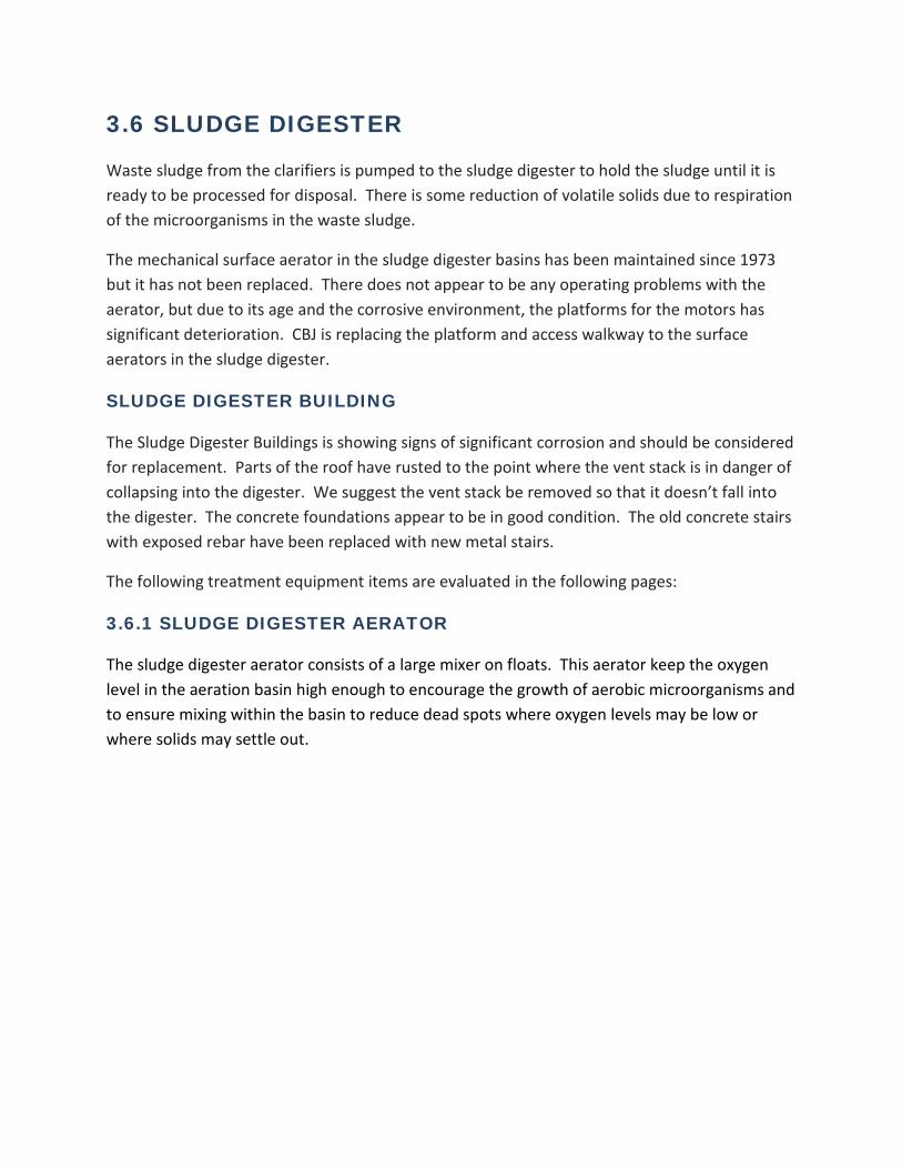
3.6.1 SLUDGE DIGESTER AERATORAGE: 41CONDITION:
ESTIMATED USEFUL LIFE: 5-15 YEARS
THIS MECHANICAL SURFACE AERATORS HAVE BEEN IN OPERATION FOR OVER 40 YEARS IN A HARSH ENVIRONMENT. MAINTENANCE HAS HISTORICALLY BEEN PERFORMED ON THE AERATOR AND IT APPEARS TO BE OPERATING SATISFACTORILY.
THERE ARE NO OBVIOUS MAINTENANCE ISSUES WITH THE AERATOR. IT CAN REASONABLY BE EXPECTED THAT THE UNIT WILL PERFORM AS REQUIRED FOR ANOTHER 5-15 YEARS WITH REGULAR MAINTENANCE. DUE TO IT'S AGE, SPECIAL ATTENTION SHOULD BE PAID TO ANY OVERHEATING ISSUES, EXCESSIVE VIBRATIONS OR UNUSUAL SOUNDS FROM THE AERATOR AS THEY MAY INDICATE EMINENT FAILURE OF THE UNIT.
AERATION BASIN AERATOR SIMILAR TO SLUDGE DIGESTER AERATOR
3.7 BELT FILTER PRESS
The belt filter press and its associated equipment, the hydraulic pressure pump and the wash water booster pump were constructed in 1990. The belt filter press has been regularly maintained and there does not appear to be any operating problems with the belt filter press or its associated equipment.
INCINERATOR BUILDING 2ND FLOOR (BELT PRESS LOCATION)
The belt filter press is located on the second floor of the Incinerator Building. The decommissioned sludge incinerator is also located in the Incinerator Building. The main structural steel for the belt filter press area is hot dip galvanized steel and appears to be in good shape. There is some trim between the concrete curb for the room and the exterior walls that is showing signs of significant corrosion and should be considered for replacement.
The following treatment equipment items are evaluated in the following pages:
3.7.1 BELT FILTER PRESS
Sludge is pumped to the belt filter press from the sludge digester. Polymer is added to the sludge to form a floc that holds together under pressure. The belt press consists of two belts that pass over rollers. Sludge is applied between the two belts and as the belts pass over the rollers the sludge is squeezed between the belts to force out water. The belt press can increase the percent solids in the sludge from about 2% up to about 15% solids.
3.7.2 BELT FILTER PRESS BOOSTER PUMP
The belts on the belt press are continuously washed to keep them free from solids. The belt filter press booster pump increased the water pressure so that the belt cleaning is more effective.
3.7.3 BELT FILTER PRESS HYDRAULIC PRESSURE PUMP
The belt filter press hydraulic pressure pump provides power for the belt tensioning system and for the belt drive motors.

JDWWTP BELT FILTER PRESS
SITE PLAN
BELT FILTER PRESS (SECOND FLOOR)
BFP HYDRAULIC PRESSURE PUMP (SECOND FLOOR)
BFP WATER BOOSTER PUMP (SECOND FLOOR)

3.7.1 BELT FILTER PRESSAGE: 24 YRSCONDITION:
ESTIMATED USEFUL LIFE: 10-20 YEARS
THE BELT FILTER PRESS WAS INSTALLED AT THE SAME TIME THE SLUDGE INCINERATOR WAS CONSTRUCTED, ABOUT 24 YEARS AGO. THE BELT FILTER PRESS IS REGULARLY CLEANED AND MAINTAINED.
THERE ARE NO OBVIOUS MAINTENANCE ISSUES WITH THE BELT FILTER PRESS. IT CAN REASONABLY BE EXPECTED THAT THE UNIT WILL PERFORM AS REQUIRED FOR ANOTHER 10-20 YEARS WITH REGULAR MAINTENANCE.
BELT FILTER PRESS

3.7.2 BELT FILTER PRESS (BFP) WATER BOOSTER PUMPAGE: 24 YRSCONDITION:
ESTIMATED USEFUL LIFE: 10-20 YEARS
THE BELT FILTER PRESS WATER BOOSTER PUMP WAS INSTALLED AT THE SAME TIME THE SLUDGE INCINERATOR WAS CONSTRUCTED, ABOUT 24 YEARS AGO. THE BELT FILTER PRESS WATER BOOSTER PUMP IS REGULARLY MAINTAINED BUT IS SHOWING SIGNS OF RUST FROM THE CORROSIVE ENVIRONMENT. THE BOOSTER PUMP WAS REPLACED AND COUPLED TO THE EXISTING DRIVE MOTOR.
THERE ARE NO OBVIOUS MAINTENANCE ISSUES WITH THE BELT FILTER PRESS WATER BOOSTER PUMP. IT CAN REASONABLY BE EXPECTED THAT THE UNIT WILL PERFORM AS REQUIRED FOR ANOTHER 10-20 YEARS WITH REGULAR MAINTENANCE.
BELT FILTER PRESS WATER BOOSTER PUMP

3.7.3 BELT FILTER PRESS (BFP) HYDRAULIC PRESSURE PUMPAGE: 24 YRSCONDITION:
ESTIMATED USEFUL LIFE: 10-20 YEARS
THE BELT FILTER PRESS HYDRAULIC PRESSURE PUMP WAS INSTALLED AT THE SAME TIME THE BELT FILTER PRESS WAS CONSTRUCTED, ABOUT 24 YEARS AGO. THE BELT FILTER PRESS HYDRAULIC PRESSURE PUMP IS REGULARLY MAINTAINED BUT IS SHOWING SIGNS OF RUST FROM THE CORROSIVE ENVIRONMENT.
THERE ARE NO OBVIOUS MAINTENANCE ISSUES WITH THE BELT FILTER PRESS HYDRAULIC PRESSURE PUMP. IT CAN REASONABLY BE EXPECTED THAT THE UNIT WILL PERFORM AS REQUIRED FOR ANOTHER 10-20 YEARS WITH REGULAR MAINTENANCE.
BELT FILTER PRESS HYDRAULIC PRESSURE PUMP
3.8 SLUDGE FEED SYSTEM
The sludge feed system consisting of the sludge feed pump, sludge grinder, polymer mixers and the polymer feed pump were constructed in 1990. The pumps and polymer system have been regularly maintained and there does not appear to be any operating problems with the sludge feed pump or its associated equipment.
INCINERATOR BUILDING BASEMENT (SLUDGE PUMP AND SLUDGE GRINDER LOCATION), 1ST FLOOR (POLYMER MIXERS AND POLYMER FEED PUMP LOCATION)
The sludge feed system is housed in basement of the sludge incinerator building. The concrete and main structural steel for the sludge feed room appears to be in good shape. The following treatment equipment items are evaluated in the following pages:
3.8.1 BFP SLUDGE FEED PUMP
The BFP sludge feed pump transfers liquid waste sludge from the sludge digester to the belt press. The pump is a progressive cavity pump that is controlled by variable speed drives so that the rate at which sludge is applied to the belt press can be controlled.
3.8.2 SLUDGE GRINDER
The sludge grinder macerates the sludge before it is pumped to the belt press to make sure that there are no lumps or clumps of material that would interfere in the operation of the belt filter press.
3.8.3 POLYMER MIXER NO. 1 AND NO. 2
Polymer is made in batches by adding a liquid or dry concentrated polymer to water and then blending the mixture. The polymer is typically made in advance so that it has the opportunity to rest before it is added to sludge.
3.8.4 POLYMER FEED PUMP
The polymer feed pump is a progressive cavity pump that is controlled by a variable frequency drive so that the amount of polymer added to the sludge can be carefully controlled to ensure the sludge can be dewatered to the maximum extent possible.
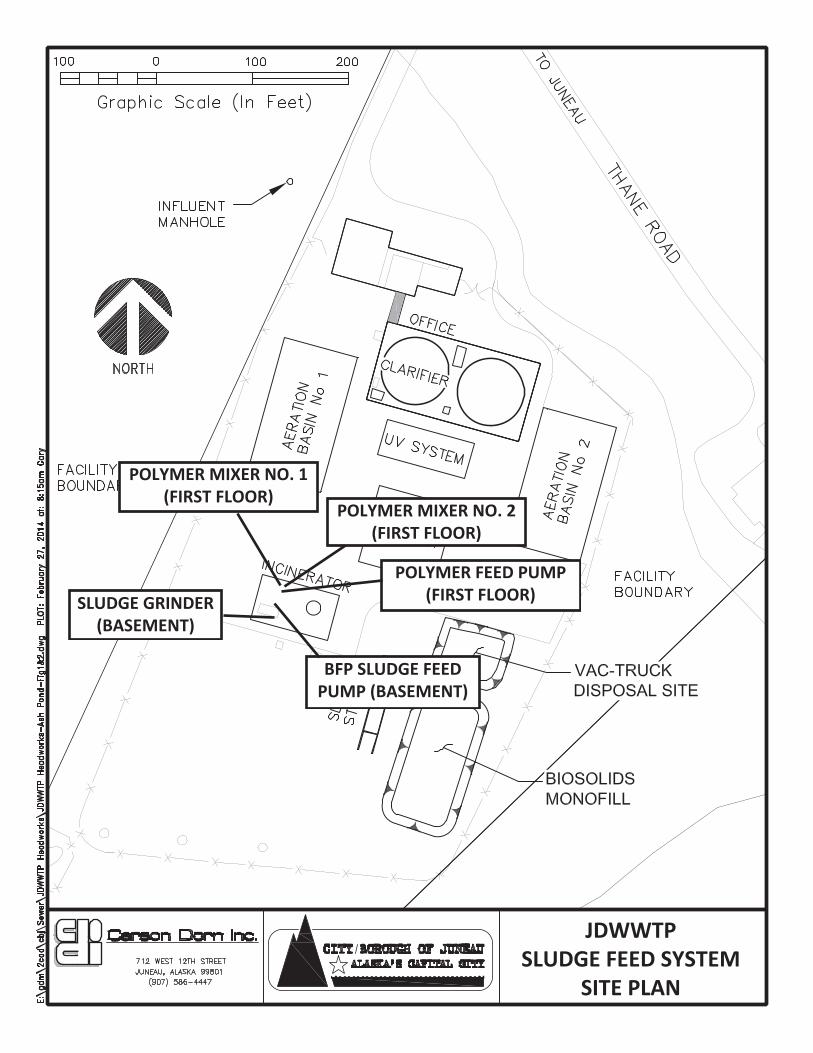
JDWWTP SLUDGE FEED SYSTEM
SITE PLAN
POLYMER MIXER NO. 1 (FIRST FLOOR)
BFP SLUDGE FEED PUMP (BASEMENT)
SLUDGE GRINDER (BASEMENT)
POLYMER MIXER NO. 2 (FIRST FLOOR)
POLYMER FEED PUMP (FIRST FLOOR)

3.8.1 BFP SLUDGE FEED PUMPAGE: 24 YRSCONDITION:
ESTIMATED USEFUL LIFE: 20-30 YEARS
THE BFP SLUDGE FEED PUMP WAS INSTALLED AT THE SAME TIME THE BELT FILTER PRESS WAS CONSTRUCTED, ABOUT 24 YEARS AGO. THE BFP SLUDGE FEED PUMP IS REGULARLY MAINTAINED AND IS CURRENTLY OPERATING WITHOUT PROBLEMS.
THERE ARE NO OBVIOUS MAINTENANCE ISSUES WITH THE BFP SLDUGE FEED PUMP. IT CAN REASONABLY BE EXPECTED THAT THE UNIT WILL PERFORM AS REQUIRED FOR ANOTHER 20-30 YEARS WITH REGULAR MAINTENANCE.
BELT FILTER PRESS SLUDGE FEED PUMP
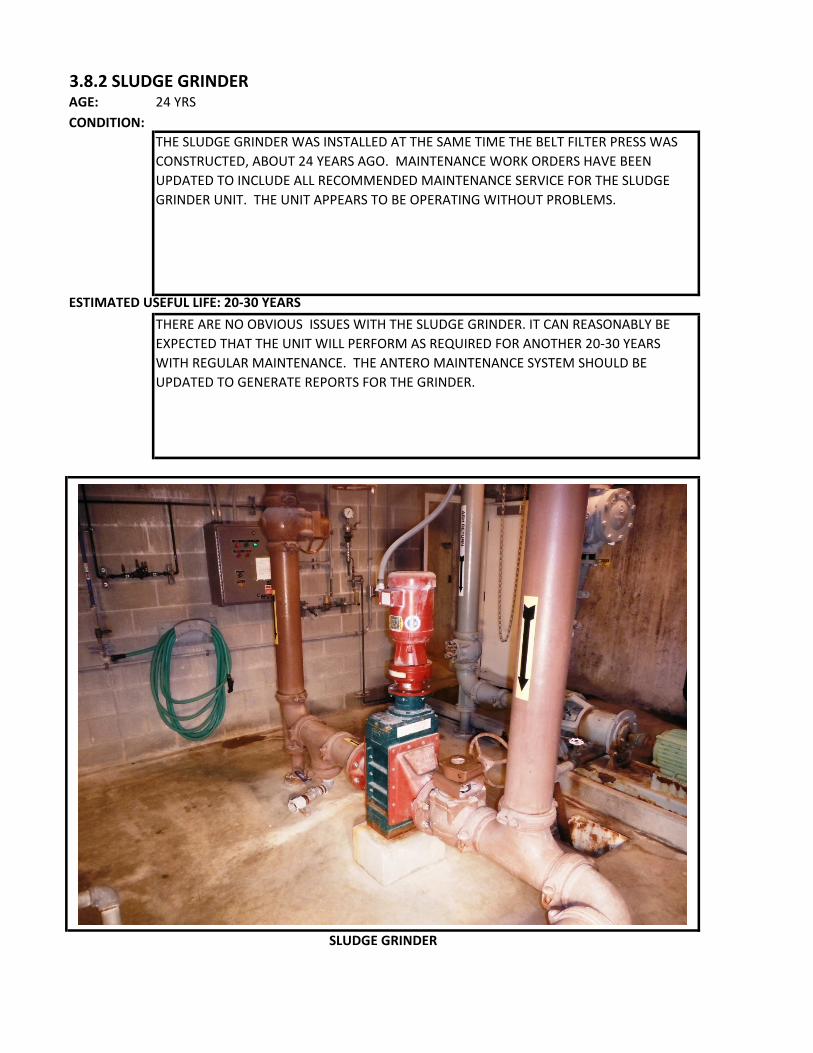
3.8.2 SLUDGE GRINDERAGE: 24 YRSCONDITION:
ESTIMATED USEFUL LIFE: 20-30 YEARS
THE SLUDGE GRINDER WAS INSTALLED AT THE SAME TIME THE BELT FILTER PRESS WAS CONSTRUCTED, ABOUT 24 YEARS AGO. MAINTENANCE WORK ORDERS HAVE BEEN UPDATED TO INCLUDE ALL RECOMMENDED MAINTENANCE SERVICE FOR THE SLUDGE GRINDER UNIT. THE UNIT APPEARS TO BE OPERATING WITHOUT PROBLEMS.
THERE ARE NO OBVIOUS ISSUES WITH THE SLUDGE GRINDER. IT CAN REASONABLY BE EXPECTED THAT THE UNIT WILL PERFORM AS REQUIRED FOR ANOTHER 20-30 YEARS WITH REGULAR MAINTENANCE. THE ANTERO MAINTENANCE SYSTEM SHOULD BE UPDATED TO GENERATE REPORTS FOR THE GRINDER.
SLUDGE GRINDER
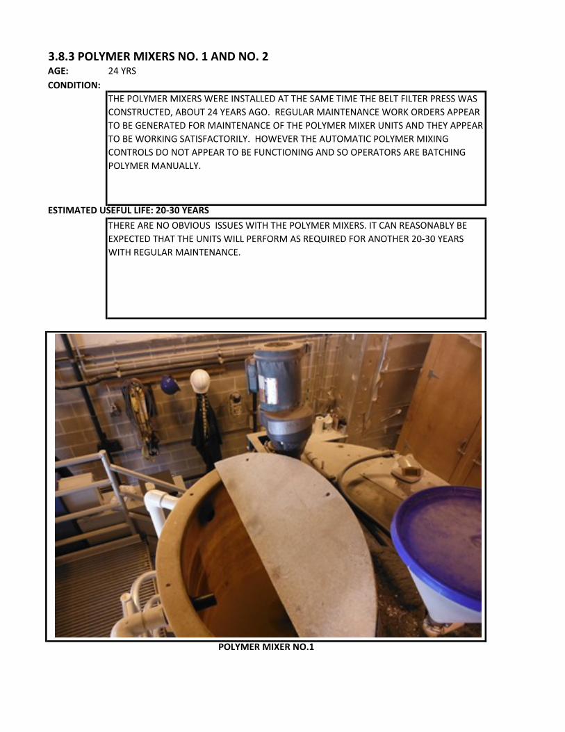
3.8.3 POLYMER MIXERS NO. 1 AND NO. 2AGE: 24 YRSCONDITION:
ESTIMATED USEFUL LIFE: 20-30 YEARS
THE POLYMER MIXERS WERE INSTALLED AT THE SAME TIME THE BELT FILTER PRESS WAS CONSTRUCTED, ABOUT 24 YEARS AGO. REGULAR MAINTENANCE WORK ORDERS APPEAR TO BE GENERATED FOR MAINTENANCE OF THE POLYMER MIXER UNITS AND THEY APPEAR TO BE WORKING SATISFACTORILY. HOWEVER THE AUTOMATIC POLYMER MIXING CONTROLS DO NOT APPEAR TO BE FUNCTIONING AND SO OPERATORS ARE BATCHING POLYMER MANUALLY.
THERE ARE NO OBVIOUS ISSUES WITH THE POLYMER MIXERS. IT CAN REASONABLY BE EXPECTED THAT THE UNITS WILL PERFORM AS REQUIRED FOR ANOTHER 20-30 YEARS WITH REGULAR MAINTENANCE.
POLYMER MIXER NO.1

3.8.4 POLYMER FEED PUMPAGE: 24 YRSCONDITION:
ESTIMATED USEFUL LIFE: 20-30 YEARS
THE POLYMER FEED PUMP WAS INSTALLED AT THE SAME TIME THE BELT FILTER PRESS WAS CONSTRUCTED, ABOUT 24 YEARS AGO. REGULAR MAINTENANCE WORK ORDERS APPEAR TO BE GENERATING FOR MAINTENANCE OF THE POLYMER FEED PUMP AND IT APPEAR TO BE WORKING SATISFACTORILY.
THERE ARE NO OBVIOUS ISSUES WITH THE POLYMER FEED PUMP AND IT CAN REASONABLY BE EXPECTED THAT THE UNIT WILL PERFORM AS REQUIRED FOR ANOTHER 20-30 YEARS WITH REGULAR MAINTENANCE.
POLYMER FEED PUMP

3.9 WASTEWATER RETURN SUMP PUMPS
The wastewater return sump pumps were constructed in 1990. The pumps have been regularly maintained but despite regular maintenance, one of the pumps has failed. CBJ is in the process of replacing both sump pumps.
INCINERATOR BUILDING BASEMENT (SUMP PUMP LOCATION)
The sump pumps are housed in basement of the sludge incinerator building adjacent to the sludge feed pump. The concrete and main structural steel for the room appears to be in good shape.
The following treatment equipment items are evaluated in the following pages:
3.9.1 WASTEWATER RETURN SUMP PUMPS NO. 1 AND NO. 2
The wastewater return sump pumps are submersible pumps that were used to return supernatant from the ash pond when the incinerator was in operation and currently returns filtrate from the belt filter to the plant headworks.

JDWWTP WASTE WATER RETURN SUMP PUMP
SITE PLAN
WASTE WATER RETURN SUMP PUMP
NO.1 (BASEMENT) WASTE WATER
RETURN SUMP PUMP NO.2 (BASEMENT)
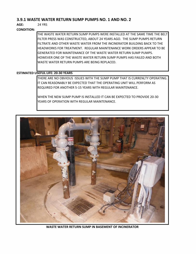
3.9.1 WASTE WATER RETURN SUMP PUMPS NO. 1 AND NO. 2AGE: 24 YRSCONDITION:
ESTIMATED USEFUL LIFE: 20-30 YEARS
THE WASTE WATER RETURN SUMP PUMPS WERE INSTALLED AT THE SAME TIME THE BELT FILTER PRESS WAS CONSTRUCTED, ABOUT 24 YEARS AGO. THE SUMP PUMPS RETURN FILTRATE AND OTHER WASTE WATER FROM THE INCINERATOR BUILDING BACK TO THE HEADWORKS FOR TREATMENT. REGULAR MAINTENANCE WORK ORDERS APPEAR TO BE GENERATED FOR MAINTENANCE OF THE WASTE WATER RETURN SUMP PUMPS. HOWEVER ONE OF THE WASTE WATER RETURN SUMP PUMPS HAS FAILED AND BOTH WASTE WATER RETURN PUMPS ARE BEING REPLACED.
THERE ARE NO OBVIOUS ISSUES WITH THE SUMP PUMP THAT IS CURRENLTY OPERATING. IT CAN REASONABLY BE EXPECTED THAT THE OPERATING UNIT WILL PERFORM AS REQUIRED FOR ANOTHER 5-15 YEARS WITH REGULAR MAINTENANCE.
WHEN THE NEW SUMP PUMP IS INSTALLED IT CAN BE EXPECTED TO PROVIDE 20-30 YEARS OF OPERATION WITH REGULAR MAINTENANCE.
WASTE WATER RETURN SUMP IN BASEMENT OF INCINERATOR

3.10 UTILITY WATER PUMPS
The utility water pumps were installed in 1990 and one of the drive motors was replaced about 3 years ago. The pumps have been regularly maintained and appear to be operating satisfactorily.
INCINERATOR BUILDING BASEMENT (UTILITY WATER PUMP LOCATION)
The utility water pumps are housed in basement of the sludge incinerator building adjacent to the incinerator. The concrete and main structural steel for the room appears to be in good shape.
The following treatment equipment items are evaluated in the following pages:
3.10.1 UTILITY WATER PUMPS NO. 1 AND NO. 2
The utility water pumps are end suction centrifugal pumps that pump treated plant effluent to a non-potable water system. This system is used to provide pressurized water for items such as spray bars in the clarifiers and spray nozzles for the auger monster.

JDWWTP UTILITY WATER PUMP
SITE PLAN
UTILITY WATER PUMP NO.2 (BASEMENT)
UTILITY WATER PUMP NO.1 (BASEMENT)

3.10.1 UTILITY WATER PUMPS NO. 1 AND NO. 2AGE: 24 YRSCONDITION:
ESTIMATED USEFUL LIFE: 20-30 YEARS
THE UTILITY WATER PUMPS WERE INSTALLED AT THE SAME TIME THE BELT FILTER PRESS WAS CONSTRUCTED, ABOUT 24 YEARS AGO. THE UTILITY WATER PUMPS PROVIDE PRESSURIZED NON-POTABLE WATER THROUGHOUT THE PLANT FOR WASHDOWN WATER AND SPRAY NOZZLES. REGULAR MAINTENANCE WORK ORDERS APPEAR TO BE GENERATED FOR MAINTENANCE OF THE UTILITY WATER PUMPS. ONE OF THE DRIVE MOTORS FOR THE UTILITY WATER PUMPS WAS REPLACED ABOUT 3 YEARS AGO.
THERE ARE NO OBVIOUS ISSUES WITH THE UTILITY WATER PUMPS. IT CAN REASONABLY BE EXPECTED THAT THE PUMPS WILL PERFORM AS REQUIRED FOR ANOTHER 20-30 YEARS WITH REGULAR MAINTENANCE.
UTILITY WATER PUMPS BASEMENT OF INCINERATOR BUILDING
4 - EQUIPMENT MAINTENANCE SCHEDULE, STAFFING AND COSTS
The CBJ uses Antero Maintenance Data Management Software for maintaining all
equipment at the JDWWTP. Over 500 Work Orders were generated and completed in
2013 for maintenance of equipment at the JDWWTP.
Despite regularly completing the work orders, there is great variability in entering data
into the completed work orders such as the employee that the completed the work and the
hours necessary to complete the task. There are also tasks that staff “know” need to be
done for which no work orders are generated. Replacing the UV lamps is an example of
a task for which there is no work order. There are also no work orders for maintenance
of the sludge grinder, although there is one for inspecting the sludge grinder controller.
The completed work orders under the Antero maintenance system were reviewed and
compared to the operation and maintenance manuals to develop the following Table 2,
JDWWTP Maintenance Schedule, Staffing and Costs. The Table contains the
maintenance activity, frequency required, estimated labor to complete the activity, annual
total labor for each activity and costs for maintaining all equipment at the JDWWTP.
Antero appears to be an older program for managing maintenance activities at the
JDWWTP but it is still functional. It is the same software package that is used for
maintenance at Juneau’s other major waste water treatment plant the Mendenhall Plant.
CBJ is evaluating other more robust facility management software systems for
implementation.
The CBJ Wastewater Utility currently staffs 3 full-time wastewater treatment operators at
the Juneau-Douglas Wastewater Treatment Plant (JDTP) for system operations and
preventative maintenance work orders. Additional resources are provided by staff, from
Carson Dorn Inc. Page 4-1

JDWWTP Facility Maintenance Evaluation Report the Mendenhall Wastewater Treatment Plant for higher level corrective work orders,
system oversight, administration, and permit compliance. The JDWWTP additionally
draws on the CBJ Engineering Division and outside consultants for system improvements
and plant upgrades.
Carson Dorn Inc. Page 4-2
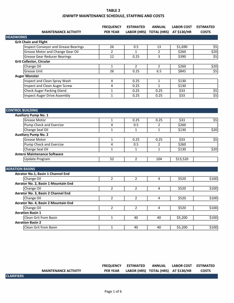
TABLE 2JDWWTP MAINTENANCE SCHEDULE, STAFFING AND COSTS
Page 1 of 6
MAINTENANCE ACTIVITYFREQUENCY
PER YEARESTIMATED
LABOR (HRS)ANNUAL
TOTAL (HRS)LABOR COST AT $130/HR
ESTIMATED COSTS
HEADWORKSGrit Chain and Flight
Inspect Conveyor and Grease Bearings 26 0.5 13 $1,690 $5Grease Motor and Change Gear Oil 2 1 2 $260 $20Grease Gear Reducer Bearings 12 0.25 3 $390 $5
Grit Collector, CircularChange Oil 1 2 2 $260 $20Grease Unit 26 0.25 6.5 $845 $5
Auger MonsterInspect and Clean Spray Wash 4 0.25 1 $130Inspect and Clean Auger Screw 4 0.25 1 $130Check Auger Packing Gland 1 0.25 0.25 $33 $5Inspect Auger Drive Assembly 1 0.25 0.25 $33 $5
CONTROL BUILDINGAuxiliary Pump No. 1
Grease Motor 1 0.25 0.25 $33 $5Pump Check and Exercise 4 0.5 2 $260Change Seal Oil 1 1 1 $130 $20
Auxiliary Pump No. 2Grease Motor 1 0.25 0.25 $33 $5Pump Check and Exercise 4 0.5 2 $260Change Seal Oil 1 1 1 $130 $20
Antero Maintenance SoftwareUpdate Program 52 2 104 $13,520
AERATION BASINSAerator No.1, Basin 1 Channel End
Change Oil 2 2 4 $520 $100Aerator No. 2, Basin 1 Mountain End
Change Oil 2 2 4 $520 $100Aerator No. 3, Basin 2 Channel End
Change Oil 2 2 4 $520 $100Aerator No. 4, Basin 2 Mountain End
Change Oil 2 2 4 $520 $100Aeration Basin 1
Clean Grit from Basin 1 40 40 $5,200 $100Aeration Basin 2
Clean Grit from Basin 1 40 40 $5,200 $100
MAINTENANCE ACTIVITYFREQUENCY
PER YEARESTIMATED
LABOR (HRS)ANNUAL
TOTAL (HRS)LABOR COST AT $130/HR
ESTIMATED COSTS
CLARIFIERS

TABLE 2JDWWTP MAINTENANCE SCHEDULE, STAFFING AND COSTS
Page 2 of 6
Clarifier No 1Check Drive Oil 12 0.25 3 $390Clean Clarifier 26 1 26 $3,380Grease Worm Drive and Check Chain 12 0.25 3 $390 $5Change Drive Oil 1 2 2 $260 $20Drive Bearing Check Points 0.3 2 0.6 $78
Clarifier No. 2Check Drive Oil 12 0.25 3 $390Clean Clarifier 26 1 26 $3,380Grease Worm Drive and Check Chain 12 0.25 3 $390 $5Change Drive Oil 1 2 2 $260 $20Drive Bearing Check Points 0.3 2 0.6 $78
Return Activated Sludge Pump No. 1Pull and Inspect-Change Oil 1 4 4 $520 $20
Return Activated Sludge Pump No. 2Pull and Inspect-Change Oil 1 4 4 $520 $20
Waste Activated Sludge Pump No. 1Grease Pump and Shaft Bearings 2 2 4 $520 $5
Waste Activated Sludge Pump No. 2Grease Pump and Shaft Bearings 2 2 4 $520 $5
UV DISINFECTIONUV Disinfection System
Clean UV Channel 52 1 52 $6,760UV System Bank A
Clean UV Modules 26 1 26 $3,380Replace lamps and sleeves 1 16 16 $2,080 $5,000
UV System Bank BClean UV Modules 26 1 26 $3,380Replace lamps and sleeves 1 16 16 $2,080 $5,000
SLUDGE DIGESTERAerator No. 5, Sludge Digester
Change Oil 2 2 4 $520 $100
MAINTENANCE ACTIVITYFREQUENCY
PER YEARESTIMATED
LABOR (HRS)ANNUAL
TOTAL (HRS)LABOR COST AT $130/HR
ESTIMATED COSTS
BELT FILTER PRESSBelt Filter Press
Grease Roller Support Bearings 2 1 2 $260 $5Grease Trunion Bearings 6 1 6 $780 $5Clean Belts 6 2 12 $1,560

TABLE 2JDWWTP MAINTENANCE SCHEDULE, STAFFING AND COSTS
Page 3 of 6
Check Gear Reducer Oil Levels 2 0.25 0.5 $65Change Oil in Gear Reducer 1 2 2 $260 $20Clean and Grease Secondary Spur Gears 1 2 2 $260 $5Regrease Secondary Spur Gears 12 0.5 6 $780 $5
Belt Filter Press Booster PumpCheck Booster Pump Bearing Temps 12 0.25 3 $390Grease Booster Pump Bearings 12 0.25 3 $390 $5
Belt Filter Press Hydraulic Pressure PumpChange Filter in Hydraulic Tank 1 1 1 $130 $30Check Hydraulic Oil Level 12 0.25 3 $390Change Oil in Hydraulic Tank 1 2 2 $260 $100
BFP SLUDGE FEED SYSTEMSludge Feed Pump
Change Gear Box Oil 0.5 2 1 $130 $50Check VFD 2 0.5 1 $130Clean Out Rag Build Up in Coupling Housing 6 1 6 $780Grease Motor 0.3 0.5 0.15 $20 $5
Sludge GrinderRetorque Fasteners 2 1 2 $260Inspect Bearings 1 1 1 $130Regrease Bearings 1 0.25 0.25 $33 $50Inspect and Regrease Top and Bottom 1 0.25 0.25 $33 $10Inspect Control Cabinet for Dust and Moisture 4 0.25 1 $130
Polymer Mixer No. 1Check Clamps 2 0.25 0.5 $65Check Oil Levels 26 0.25 6.5 $845 $5Check VFD 2 0.25 0.5 $65
Polymer Mixer No. 2Check Clamps 2 0.25 0.5 $65Check Oil Levels 26 0.25 6.5 $845 $5Check VFD 2 0.25 0.5 $65
Polymer Feed PumpInspect Pump Operation 2 0.25 0.5 $65Lubricate Pump 1 0.25 0.25 $33 $5Repalce Packing, O-Rings and Gaskets 1 2 2 $260 $100Check Bearings 1 0.25 0.25 $33 $5
MAINTENANCE ACTIVITYFREQUENCY
PER YEARESTIMATED
LABOR (HRS)ANNUAL
TOTAL (HRS)LABOR COST AT $130/HR
ESTIMATED COSTS
WASTEWATER RETURN SUMPSubmersible Sump Pump No. 1
Check Pump Operation 12 0.5 6 $780Change Seal Oil 0.5 4 2 $260 $20
Submersible Sump Pump No. 2Check Pump Operation 12 0.5 6 $780Change Seal Oil 0.5 4 2 $260 $20
UTILITY WATER SYSTEMUtility Water System and Piping

TABLE 2JDWWTP MAINTENANCE SCHEDULE, STAFFING AND COSTS
Page 4 of 6
Alternate Pumps 52 0.25 13 $1,690Utility Water Pump No. 1
Grease Bearings 2 0.25 0.5 $65 $5Check Bearing Temperature 12 0.25 3 $390
Utility Water Pump No. 2Grease Bearings 2 0.25 0.5 $65 $5Check Bearing Temperature 12 0.25 3 $390
PLANT INSTRUMENTATION
Headworks InstrumentationInspect composite sampler tubing, replace tubing as needed
12 2 24 $3,120
Calibrate composite sampler volume and verify programming
2 2 4 $520
Administration Building InstrumentationSCADA Computer-clean and service harware 2 2 4 $520SCADA check memory and disk space, perform disk cleanup
2 2 4 $520
Autodialer- Troubleshoot and modify programming as needed
2 4 8 $1,040
Effluent Turbidity Recorder- check and calibrate recorder
4 2 8 $1,040
Effluent Flow Recorder - check and calibrate recorder
1 2 2 $260
DO and pH Meter - Inspect instrument, check and calibrate both DO and pH sensors
12 2 24 $3,120
Lab Balance - verify calibration and condition 4 2 8 $1,040Lab Balance - administer contract for servicing balance and primary weights
1 4 4 $520
Clarifier Building Instrumentation#1 RAS Flow Meter - Inspect Instrument and observe for proper operation 2 1 2 $260
#1 RAS Flow VFD - Inspect drive and service as indicated 2 1 2 $260
#2 RAS Flow Meter - Inspect Instrument and observe for proper operation 2 1 2 $260
#2 RAS Flow VFD - Inspect drive and service as indicated 2 1 2 $260
MAINTENANCE ACTIVITYFREQUENCY
PER YEARESTIMATED
LABOR (HRS)ANNUAL
TOTAL (HRS)LABOR COST AT $130/HR
ESTIMATED COSTS
UV Disinfection Building InstrumentationUV Light Controller - Clean and inspect, look for operational problems 4 2 8 $1,040
Effluent Turbidimeter - Clean and calibrate instrument. Verify instrument turbidty indication on chart recorder and SCADA system
4 3 12 $1,560
Effluent Flow Meter - Verify flow meter calibrations and indications 2 3 6 $780

TABLE 2JDWWTP MAINTENANCE SCHEDULE, STAFFING AND COSTS
Page 5 of 6
Effluent composite sampler - Inspect sample pump and tubing. Repair pump and/or replace tubing as needed
12 2 24 $3,120
Effluent composite sampler - calibrate sample volume and verify programming 1 4 4 $520
Digester Building InstrumentationRadar Level Transmitter - clean and verify calibration 2 2 4 $520
WAS Flow Meter - Inspect instrument and observe for proper operation 2 2 4 $520
Belt Filter Press Building InstrumentationSludge Flow Meter - inspect instrument and observe for proper operation 2 2 4 $520
Polymer Tank Level Sensors - service as required
MISCELLANEOUS SERVICESEmergency Plant Generators
Exercise Generator 12 0.25 3 $390Emergency UV Generator
Exercise Generator 12 0.25 3 $390Automated External Defibrillator (AED)
Inspect Sign and Tag 12 0.1 1.2 $156Emergency Lighting
Check Operation of Emergency Lights 1 1 1 $130Eyewash Stations
Check Operation of Eyewash Stations 12 1 12 $1,560Fire Extinguishers
Check Fire Extinguishers 12 1 12 $1,560Fire Sprinkler System
Check fire Sprinkler System 52 0.25 13 $1,690Spare Equipment
Rotate Bearings on Spare Equipment 12 1 12 $1,560Hoists
Inspect Hoists 4 0.25 1 $130MCC Panels
Cycle Breakers 1 1 1 $130Overhead Doors
Inspect and Grease Doors 4 0.5 2 $260
MAINTENANCE ACTIVITYFREQUENCY
PER YEARESTIMATED
LABOR (HRS)ANNUAL
TOTAL (HRS)LABOR COST AT $130/HR
ESTIMATED COSTS
Sludge Pond PumpCheck Operation and Clean Intake 52 0.25 13 $1,690Change Seal Oil 1 3 3 $390 $20
Indicator LightsCheck Indicator Lights 12 0.5 6 $780
VehiclesInspect Vehicles 52 0.5 26 $3,380
ValvesExercise all valves from full open to full closed 2 16 32 $4,160
Inspect FacilityPerform Risk Management Inspection 12 1 12 $1,560

TABLE 2JDWWTP MAINTENANCE SCHEDULE, STAFFING AND COSTS
Page 6 of 6
Air Compressor UV ShopCheck Belts 4 0.25 1 $130Change Oil 2 1 2 $260 $20
Fuel Tank for Main PlantClean Fuel Tank 1 0.5 0.5 $65Inspect Tank 12 0.25 3 $390Check for Moisture 4 0.5 2 $260
Fuel Tank for Incinerator BuildingClean Fuel Tank 1 0.5 0.5 $65Inspect Tank 12 0.25 3 $390Check for Moisture 4 0.5 2 $260
ValvesLube and Exercise Valves 1 1 1 $130 $5
WeatherizationPrepare JDWWTP for Winter 1 2 2 $260
Perimeter SecuityPrepare JDWWTP for Winter 1 2 2 $260Daily Security Checks 208 0.25 52 $6,760
TOTALS 958.05 $124,547 $11,420

5 – FIVE YEAR CAPITAL REPLACEMENT CHART The estimated useful life of the existing equipment was reviewed and any equipment that
had a useful life of less than 15 years was included in Table 3, Estimated 5-Year Capital
Replacement Fund. Since it is not possible to predict when equipment will need to be
replaced, the cost of replacing each equipment item was distributed over the 15 year
period to represent projected average capital improvements needs over a 15 year period.
In general Table 3 indicates that equipment replacement costs might be on the order of
$35,000 to $40,000 per year over the next 15 years in order to generate a sufficient
reserve fund for replacing major equipment items as they no longer perform as intended.
Carson Dorn Inc. Page 5-1

ITEMESTIMATED
COSTESTIMATED USEFUL LIFE
5 YR 10 YR 15 YR
Grit Chain Drive, Motor and Gear Reducer
$30,000 15 $10,000 $10,000 $10,000
Grit Chamber Drive and Rake
$60,000 15 $20,000 $20,000 $20,000
Aerator No. 1 $75,000 15 $25,000 $25,000 $25,000Aerator No. 2 $75,000 15 $25,000 $25,000 $25,000Aerator No. 3 $75,000 15 $25,000 $25,000 $25,000Aerator No. 4 $75,000 15 $25,000 $25,000 $25,000Aerator No. 5 $75,000 15 $25,000 $25,000 $25,000WAS Pump No. 1 $10,000 15 $3,333 $3,333 $3,333WAS Pump No. 2 $10,000 15 $3,333 $3,333 $3,333Valves and Piping from 1973
$60,000 15 $20,000 $20,000 $20,000
Wastewater Return Pump No. 1
$5,000 15 $1,666 $1,666 $1,666
$183,332 $183,332 $183,332
TABLE 3ESTIMATED 5-YEAR CAPITAL REPLACEMENT FUND