carbothermic smelting of tavas manganese ore, turkey
TRANSCRIPT

Carbothermic Smelting Of Tavas Manganese Ore, Turkey
Onuralp Yiicel and M. Emin Ari
Istanbul Technical University, Chemistry and Metallurgy Faculty, Metallurgical and Materials Engineering Department,
80626 Maslak, Istanbul, Turkey
(Received June 11,2001.)
ABSTRACT
Ferromanganese and silicomanganese were produced by carbothermic methods from the Denizli-Tavas manganese ores containing 43.4 % Mn. Reduction smelting experiments were carried out in a 270 kVA laboratory scale electric arc furnace. Ferromanganese containing 85.1 % Mn, 1.0 % Si was produced by 82.1 % manganese recovery with charge containing 16.7 % coke and 12.4 % CaO. Silicomanganese containing 69.7 % Mn, 18.2 % Si was obtained by using charge mixing of ore and silica sand containing 19.0 % coke with 70.7 % manganese recovery.
1. INTRODUCTION
Manganese is an element that is added to molten steel in the form of ferromanganese and silico-manganese for alloying and/or deoxidizing and sulfur-fixing. Ninety percent of world manganese production is consumed as ferromanganese and silicomanganese in iron and steel production /1-3/. The world's total production of these ferroalloys is about 6.5-7 million tons and the distribution of consumption can be characterized as: 47 % high carbon ferromanganese (HC FeMn), 42 % silicomanganese (SiMn), and 11 % low carbon ferromanganese (LC FeMn) /4,5/. Although Turkey's total steel production is more than 14 million tons/year, these ferroalloys have not been produced from domestic sources. Turkey imported 29,360 tons of
ferromanganese and 90,700 tons of silicomanganese in 1999/6,7/.
The main commercial processes for manganese alloy production are carbothermic, carbothermic/silicothermic and metallothermic processes 111. Today the dominating production method of ferromanganese and silico-manganese is the smelting of a charge containing manganese ore or ferromanganese production slags in an electric arc furnace at reducing conditions. High-carbon ferromanganese and silicomanganese are produced by carbothermic reduction in blast furnaces (BF) or in electric furnaces (EAF), whereas medium-and low-carbon ferromanganese are produced by decarburisation of high carbon ferromanganese or by silicothermic reduction of MnO dissolved in slag /8/. Types of process, energy consumption and recovery of manganese of these production processes are shown in Table 1 /3,9-13/. It is obvious that the carbothermic processes have high electric energy and coke consumptions. Manganese recovery as ferroalloy can be as high as 60 to 80 % in the EAF processes.
The total amount of manganese metal in Turkish manganese ores is estimated to be over 1.5 million tons /14/. The leading manganese ore with a 43.4 % Mn concentration is located in Denizli, Tavas area.
In this study, parameters for ferromanganese and silicomanganese production from the Denizli Tavas manganese ore by carbothermic reduction smelting have been investigated in a laboratory scale direct current (dc) electric arc furnace (EAF). The effects of reducing material and flux that is added to the charge in varying
345 Brought to you by | UZH Hauptbibliothek / Zentralbibliothek Zürich
Authenticated | 130.60.206.43Download Date | 8/6/13 9:09 PM

Vol. 20, Nos. 5-6, 2001 Carbothermic Smelting ofTavas Manganese Ore, Turkey
Table 1 Energy and Coke Consumptions in Ferromanganese and Silicomanganese Productions.
Products Process Mn Recovery, Energy Consumption, Coke, % (kWh/t) kg/t
HC FeMn EAF 60-75 2600-2800 350 BF 80-85 - 2000
SiMn EAF 70-80 3500-4200 850-1000 LC FeMn EAF 60-85 1600-1900 -
Metallic Mn Metallothermic 63-85 - -
Electrometallurgy 70-87 9000 -
amounts, on manganese and impurity concentrations in ferroalloy and manganese recovery were examined.
2. EXPERIMENTAL
2.1. Raw Materials
The manganese in the Tavas ore is in the form of Mn203 and MnC03 . The elemental composition of the ore is 43.42 % Mn, 12.70 % Si, 4.21 % Ca, 3.21 % Fe, 3.04 % C, % 0.79 Al, 0.67 % Mg, 0.021 % S, 0.04 % P. The reductant coke used in the experiments has a composition of 82.19 % fixed carbon, 4.12 % volatile matter, and 13.68 % ash. The coke ash contains 47.50 % Si02, 8.52 % Fe, 7.61 % Ca, 12.65 % Al, 2.70 % Mg. In experiments for the production of low silicon ferromanganese, CaO obtained through calcination of a 99.5 % pure CaC03 at 1000°C was used as the fluxing agent. For the production of silicomanganese, Si02 with 99.5 % purity was used.
2.2. Experimental Apparatus
A lab scale, mono phase, submerged electric arc furnace lined with magnesia, powered with a 270 kVA dc transformer, was used in this study /15-17/. The heart of the furnace crucible has a conical shape with a diameter of 15 cm on the top and 11 cm at the bottom and a height of 35 cm. While the graphite bottom electrode is fixed in the refractory material of the furnace, the top graphite electrode has the ability to move in a vertical axis.
2.3. Experimental Procedure
Depending on the intended final product, 1 kg of manganese ore was mixed with coke and CaO or Si02, and directly transferred to the arc furnace after a homogeneous mixing. After every 30-minute smelting period, the upper electrode was lifted up to stop the arc, and the temperature of the slag was measured by using a submerged Pt-PtRhl0 thermocouple. When the furnace cooled down, metal and slag were separated, weighed and analyzed.
3. RESULTS AND DISCUSSION
3.1. Ferromanganese
Effect of Coke Addition Upper graphite electrodes with diameters of 3.5, 4
and 5 cm were used in our experiments, for the production of ferromanganese. Higher refractory erosion was detected as a result of higher temperature reached in the experiments where the 5 cm diameter electrode was used. This also caused the smelting regime to behave in an irregular manner. As a result of these drawbacks only 3.5 and 4 cm diameter electrodes were used in the remaining experiments.
Smelting experiments were conducted up to 40 min. to determine the effect of reduction duration on metal concentrations in the alloy and manganese recovery, and the results are shown in Figure 1. When the charge containing 16.7 % coke was smelted with a 4 cm diameter electrode, the stability of the smelting regime
346 Brought to you by | UZH Hauptbibliothek / Zentralbibliothek Zürich
Authenticated | 130.60.206.43Download Date | 8/6/13 9:09 PM

Ο. Yucel and Μ. Emin Ari High Temperature Materials and Processes
90
80
70
ί 60 3K 0 50 Ϊ c 40 c S 30
20
10
0
° • Β
A A
A •
10 15 20 25
Time, min
• 100
• 90
• 8 0
• 70
•60 • 50
• 4 0
• 30
-20 30 35 40 45
Fig. 1: Changes of manganese in metal, and manganese recovery as a function of smelting time. (A , • : 4 cm diameter electrodes, Δ, • : 3.5 cm diameter electrodes.)
f <
15 16 17 18 Cok· / Charg·, %
Fig. 2: Changes of manganese and silicon concentration in metal, and manganese recovery as a function of coke in charge. ( A , • , · : 4 cm diameter electrodes, Δ, • , O: 3.5 cm diameter electrodes.)
became irregular after 25 minutes because of over-heating of the charge, and thus manganese concentration in metal and its recovery decreased. Maximum manganese concentration in metal (82.0 %) and recovery (77.8 %) was obtained by smelting for 25 min. When the charge was smelted with a 3.5 cm diameter electrode, maximum recovery (73.2 %) was obtained by smelting for 30 min. In these conditions, manganese concentration in metal was 78.6 %.
The amount of the coke content of the charge was also changed to obtain the highest manganese recovery and concentration in ferroalloy. Increasing the coke amount in the charge increased the recovery and the concentration of manganese in the metal by using 3.5 and 4 cm diameter electrodes (Figure 2). However in these conditions, silicon concentration in the metal exceeded the limits given in DIN 17564 (1.5 %).
When the charge containing 18.7% coke was smelted for 30 min with a 3.5 cm diameter electrode, manganese concentration in ferromanganese and its recovery was 79.3 % and 75.8 % respectively. But silicon concentration in this alloy was determined as 5.5%. It was found that, in the experiment carried out with 4 cm diameter electrode and 16.7 % coke in charge, the stability of the smelting regime became irregular after 25 minutes. The results given in Figure 2 were obtained from the experiments that were carried out for 25 minutes. In these experiments manganese and silicon concentration in ferroalloy and manganese
recovery was 82.0 %, 2.76 % and 77.8 °/Ω respectively. Increasing the reductant amount in the charge caused
iron concentration in the ferroalloy to decrease up to 6.5%, but had no effect on the carbon concentration (5-6%). The phosphor content of the alloys varied between 0.08-0.15%.
The distribution of metals within different phases is described as distribution ratio and defined as the ratio of any metal (Me = Mn, Fe, Si) in any of the phases (metal, slag, lost) to the amount of the same metal in the ore:
DMe= [Me % * phase weight / Me % * Ore weight]
Figure 3 represents the change of distribution ratio of manganese in the metal, slag and lost phases as a function of the slag temperature that was measured with a submerged Pt-PtRhl0 thermocouple. These experi-ments were carried out with the 3.5 cm diameter electrode with a charge containing 16.7 % fixed carbon. Elements reacting with furnace refractory and escaping from the system as volatile gases are accepted and calculated as the lost material. The changes of manganese concentrations in slag and in metal as a function of the slag temperature are given in Table 2. It was also previously shown that electrode diameter and smelting time have a direct effect on the slag temperature /18/. It is clear that increase in slag temperature caused an increase in the distribution ratio
347 Brought to you by | UZH Hauptbibliothek / Zentralbibliothek ZürichAuthenticated | 130.60.206.43
Download Date | 8/6/13 9:09 PM

Vol. 20, Nos. 5-6, 2001 Carbolhermic Smelting ofTavas Manganese Ore, Turkey
a S
1513 1613 1763 1808
Slag Temperatute, Κ
1953
Fig. 3: Distributions of manganese among metal, slag and gas phases as a function of the slag temperature.
Table 2 Changes of manganese concentrations in slag (% Mn)
and in metal [% Mn] as a function of the slag temperature.
Temperature, Κ 1513 1613 1763 1808 1953
(% Mn) 18.60 21.06 23.02 34.23 30.11
f% Mn] 78.55 79.31 79.15 82.62 78.54
of manganese in slag and gas phases. Optimum production parameters are described as
conditions where maximum concentration and recovery are obtained in the experiments. Distributions of manganese, iron and silicon among metal, slag and lost material are given in Figure 4 as bar graphs for smelting of the charge with no flux addition at optimum production conditions (in the experiment carried out with 4 cm diameter electrode and 16.7 % coke in charge). In these conditions, the distribution ratios of manganese are 77.7 %, 10.1 % and 12.1 % in metal, slag and lost phases respectively. The silicon distributed 19.2 % in metal and 77.9 % in slag.
Effect ofCaO Addition Although recovery of manganese and manganese
concentration in ferromanganese were quite acceptable, flux addition was necessary in order to decrease the silicon concentration in the ferroalloy to given standard
ο = 3 a 5
[Mn] [Fe] [Si]
Fig. 4: Distribution of manganese, iron and silicon between metal (ferromanganese) and slag after reduction smelting of the charge having no CaO addition (Metal contains 82.0 % Mn, 9.38 % Fe, 2.76 % Si and 5.33 % C).
limits. Experiments investigating the effect of flux addition were done with 4 cm diameter electrodes with the charge containing 16.7 % coke. CaO was chosen as the flux and was added to the charge in various amounts to investigate its effect on silicon and manganese concentration in metal, and manganese recovery.
Changes in the silicon concentration in the metal, and the manganese concentration in the slag as a function of the total CaO content in the charge are shown in Figure 5. Total CaO is the sum of the added
10 9
8
7
6
5
4
3
2
1 0
—·—[%Si] 0
o.
' •-0--0
50
•45
• 40
• 35
• 30
25
• 20
• 15
10 • 5
0
Fig. 5:
4 6 8 10 12 14 16 18 20 22
CaO in charge, %
Changes of silicon in metal and manganese in slag as a function of CaO in the charge ([% Si]: silicon in metal by weight %, (% Mn): manganese in slag by weight).
348 Brought to you by | UZH Hauptbibliothek / Zentralbibliothek Zürich
Authenticated | 130.60.206.43Download Date | 8/6/13 9:09 PM
Ο. Yucel and Μ. Em in Ari High Temperature Materials and Processes
CaO, CaO in the ore and in the coke ash. It was observed that silicon in the alloy and manganese in the slag decreased to 0.84 % and 1.89 % respectively by the charge having 14.1 % CaO. But when an excess amount of CaO (18.6 %) was added to the charge, the silicon in the metal and manganese in the slag increased dramatically.
A maximum manganese concentration of 85.1 % in ferromanganese was obtained by using the charge with 12.4 % CaO. Under these conditions the manganese recovery was 82.1 %, as shown in Figure 6.
2 4 6 8 10 12 14 16 18 20 22 CaO in Charge,%
Fig. 6: Changes in concentration of manganese in metal and recovery as a function of varying amount of CaO in charge.
Manganese concentration in metal decreased to 77.7 % when CaO concentration increased to 18.6 %. It was determined that an excess increase in the CaO concentration in the charge (over 14.1 %) increases the slag temperature, which in turn, increases the manganese concentration in the slag. This also causes manganese recovery to decrease to 60.5 %.
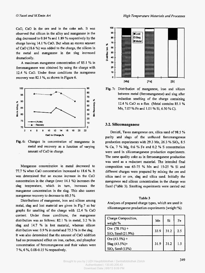
Distributions of manganese, iron and silicon among metal, slag and lost material are given in Fig.7 as bar graphs for smelting of the charge with 12.4 % CaO content. Under these conditions, the manganese distribution was as follows: 82.1 % in metal, 3.2 % in slag and 14.7 % in lost material, whereas silicon distribution was: 0.9 % in metal and 75.3 % in the slag. It was also determined that the amount of CaO addition had no pronounced effect on iron, carbon, and phosphor concentration of ferromanganese and their values were 7 %, 6 %, 0.08-0.15 % respectively.
loo j 90-80-70-
se c fiO-· ο a 50·· •Q 50·· 5 • 40 -Q
30-· 20·· 10-· 0--
[Mn] [Fe] [Si]
Fig. 7: Distribution of manganese, iron and silicon between metal (ferromanganese) and slag after reduction smelting of the charge containing 12.4 % CaO as a flux (Metal contains 85.1 % Mn, 7.07 % Fe and 1.01 % Si, 6.50 % C).
3.2. Silicomanganese
Denizli, Tavas manganese ore, silica sand of 98.5 % purity and slags of the unfluxed ferromanganese production experiments with 29.3 Mn, 26.3 % Si02, 8.5 % Ca, 7 % Mg, 0.6 % Fe and 0.2 % S concentration were used in silicomanganese production experiments. The same quality coke as in ferromanganese production was used as a reductant material. The intended final composition was 65-75 % Mn and 15-25 % Si and different charges were prepared by mixing the ore and silica sand or ore, slag and silica sand. Initially the manganese and silicon concentration in the charge was fixed (Table 3). Smelting experiments were carried out
Table 3 Analyses of prepared charge types, which are used in silicomanganese production experiments (weight %).
Charge Composition, weight %
Mn Si Fe
Ore (78.1%) + Si02 Sand (21.9%)
33.9 31.2 2.5
Ore (43.5%) + Slag (43.5%)+ Si02 Sand (13%)
31.9 31.2 1.5
349 Brought to you by | UZH Hauptbibliothek / Zentralbibliothek ZürichAuthenticated | 130.60.206.43
Download Date | 8/6/13 9:09 PM

Vol. 20, Nos. 5-6, 2001 Carbothermic Smelting ofTavas Manganese Ore, Turkey
for 30 minutes in the same DC arc furnace with a 4 cm diameter top electrode.
Figure 8 represents the variation of the manganese and silicon concentration in the metal as a function of coke amount in the charge. The highest manganese concentration, from the ore and silica sand mixture, was 69.7 % when fixed carbon in charge was 15.6 %. However in silicomanganese produced from the ore, silica sand and slag mixture, the manganese concentration was 78.0 % when fixed carbon was 17.0%.
90
80
70 ss > 60 ο < 50 c
40 in c 30 S
20
10
0
•
[Mn %]
[Si %]
•
15 16 17 18 19 20 21 22 23 24 25 26 27
Coke I Charge, %
Fig. 8: Changes in manganese and silicon concentrations in metal as a function of the coke amount in the charge. ( • , O : charges prepared from ore and silica, • , # :charges prepared from ore, silica and slag.)
In experiments with the manganese ore and silica sand mixture as the initial charge, an increase in reductant material caused an increase in the silicon concentration in metal, and was found to reach 18.5 % when the fixed carbon was 18.0 %. Moreover, in experiments with manganese ore, slag and silica sand as the initial charge, an increase in reductant material caused an increase in the silicon concentration in metal up to 22.1 %.
Figure 9 shows the variation of the manganese recovery as a function of the coke amount in the charge. It is clearly visible that, the highest manganese recovery from the charge with ore and silica sand was 70.7 % when fixed carbon was 15.6 %. The highest manganese recovery from the charge with ore, silica sand and slag
90
80
70
60
50
40
30
20
10
0
A :0re+Si02 Δ :0re+Si02+Slag
15 16 17 18 19 20 21 22 23 24 25 26 27
Coke I Charge, %
Fig. 9: Change in manganese recovery as a function of the coke amount in the charge.
was determined as 69.5 % when fixed carbon was 17.0 %.
Distributions of manganese, iron and silicon among metal, slag and lost material are given in Fig. 10 for smelting of the charge mixture of ore and silica sand. Under these conditions, the manganese distribution was as follows: 70.0 % in metal, 7.0 % in slag and 23.0 % in lost material, whereas silicon distribution was: 30.9 % in metal and 20.5 % in slag and 48.6 % in lost material.
Fig. 10: Distribution of manganese, iron and silicon between metal (silicomanganese) and slag after reduction smelting (Metal contains 69.7 % Mn, 18.2 % Si, 8.44 % Fe and 3.55 % C).
It was determined that iron concentration in metal is not affected by the change of the amount of reductant in the charge. Iron concentration in the final metal
350 Brought to you by | UZH Hauptbibliothek / Zentralbibliothek Zürich
Authenticated | 130.60.206.43Download Date | 8/6/13 9:09 PM

Ο. Yucel and Μ. Emin Ari High Temperature Materials and Processes
products from charge mix of manganese ore and silica sand, and charge of manganese ore, silica sand and slag were 6.5-8.6 % and 4.9-5.4 % respectively. Carbon content of the alloys varied between 2.9-4.1 % and 2.2-2.8 % respectively.
The increase in fixed carbon amount had no effect on phosphor concentration in the metal, and varied between 0.15 % and 0.23 %.
4. CONCLUSION
In this work, starting from a manganese ore containing 43.42 % Mn and coke mixture, ferro-manganese and silicomanganese were produced by carbothermic reduction smelting in a lab scale de EAF. The main results are summarized as follows: 1) Ferromanganese containing 85.1 % Mn and 1.0 % Si
was obtained with 82.1 % manganese recovery when 13.7 % fixed carbon and 7.7 % CaO was added to the charge, and smelted for 30 minutes.
2) Silicomanganese containing 69.7 % Mn and 18.2 % Si was produced with 70.7 % manganese recovery when 15.6 % fixed carbon was added to the charge mixture of ore and silica sand, and smelted for 30 minutes.
ACKNOWLEDGEMENT
Both authors express their appreciation for the financial support provided by Research Foundation of Istanbul Technical University. The authors also thank Prof. Dr. Okan Addemir and Dr. Filiz Qmar §ahin for their encouragements and for their help.
REFERENCES
1. G. Volkert and K.D. Frank, Metallurgie der Ferrolegierungen, Springer Verlag Berlin, Heidelberg, New York, 1972; pp. 393.
2. Ullman's Encyklopädie Der Technischen Chemie, 16, Mangan, 1978; pp. 425 .
3. F.P. Edrenal, Electrometallurgy of Steel and Ferroalloys, Vol. 2, Mir Publishers, Moscow, 1979; pp. 203.
4. S.J. Thomas, Manganese, U.S. Geological Survey Minerals Yearbook, 1999; pp. 49.
5. M. D. Fenton, Ferroalloys-1999, www.usgs.org. 6. 1996 Report of State Institute of Statistics, Prime
Ministry, Republic of Turkey. 7. S. Aydin, O. Yücel, C. Arslan and A. Köksal,
INFACON 9, The Ninth International Ferroalloys Congress, Quebec City, Canada, 3-6 June 2001.
8. Ding W and Olsen SE, Metallurgical And Materials Transaction B, 27b, 5 (1996).
9. M. Riss and Y. Khodorovsky, Production of Ferroalloys, Mir Publishers, Moscow, 1967; pp. 144.
10. X. Xiaoxing and L. Daolin, INFACON 8, Proc. of the 8'h Int. Ferroalloys Congress, Beijing, 1998; pp. 226.
11. S.Li and D. Wei, INFACON 8, Proc. of the 8'h Int. Ferroalloys Congress, Beijing, 1998; pp. 232.
12. J. Pais, W. Brown and M.W. Saab, INFACON 8, Proc. of the 8th Int. Ferroalloys Congress, Beijing, 1998; pp. 237.
13. Z. Tangke, INFACON 8, Proc. of the 8'h Int. Ferroalloys Congress, Beijing, 1998; 247.
14. Steel and Iron Raw Materials Report, State Planning Organization, Prime Ministiy, Republic of Turkey, Ankara (1988).
15. O. YUcel, O. Addemir and A. Tekin, INFACON 6, Proc. of the 6,h Int. Ferroalloys Congress, Cape Town, Johannesburg, SAIMM, 1992; Vol. 1, p. 285.
16. O. YUcel, O. Addemir, F. Qmar and A. Tekin, INFACON 7, Proc. of the 7,h Int. Ferroalloys Congress, Trondheim, 1995; pp. 647.
17. O. YUcel, F. Qinar, B. §irin and O. Addemir, Scandinavian J. of Metallurgy, 28 (3), 93 (1999).
18. M.E. An, Master's Thesis, Istanbul Technical University (1996).
351 Brought to you by | UZH Hauptbibliothek / Zentralbibliothek Zürich
Authenticated | 130.60.206.43Download Date | 8/6/13 9:09 PM

Brought to you by | UZH Hauptbibliothek / Zentralbibliothek ZürichAuthenticated | 130.60.206.43
Download Date | 8/6/13 9:09 PM