carbon-supported, nano-structured, manganese oxide composite electrode for electrochemical...
TRANSCRIPT

A
iubfe©
K
1
rttadtF
pcdbsotltr
0d
Available online at www.sciencedirect.com
Journal of Power Sources 173 (2007) 1024–1028
Short communication
Carbon-supported, nano-structured, manganese oxide compositeelectrode for electrochemical supercapacitor
Raj Kishore Sharma, Hyung-Suk Oh, Yong-Gun Shul, Hansung Kim ∗Department of Chemical Engineering, Yonsei University, 134 Shinchon-Dong, Seodaemun-gu, 120-749 Seoul, Republic of Korea
Received 11 May 2007; received in revised form 2 August 2007; accepted 8 August 2007Available online 2 September 2007
bstract
Carbon-supported MnO2 nanorods are synthesized using a microemulsion process and a manganese oxide/carbon (MnO2/C) composite isnvestigated for use in a supercapacitor. As shown by high-resolution transmission electron microscopy the 2 nm × 10 nm MnO2 nanorods are
niformly dispersed on the carbon surface. Cyclic voltammograms recorded for the MnO2/C composite electrode display ideal capacitive behaviouretween −0.1 and 0.8 V (vs. saturated calomel electrode) with high reversibility. The specific capacitance of the MnO2/C composite electrodeound to be 165 F g−1 and is estimated to be as high as 458 F g−1 for the MnO2. Based on cyclic voltammetric life-cycle tests, the MnO2/C compositelectrode gives a highly stable and reversible performance for up to 10,000 cycles.2007 Elsevier B.V. All rights reserved.
lsion;
0apmiptlsopfiratvM
eywords: Supercapacitor; Manganese oxide; Composite electrode; Microemu
. Introduction
In recent years, electrochemical supercapacitors haveeceived a considerable amount of attention due to their abilityo deliver high specific power [1]. Based on their fundamen-al charge-storage mechanism, supercapacitors are categorizeds electrical double-layer capacitors (ELDCs) or Faradic pseu-ocapacitors. The former stores energy by charge separation athe electrode and electrolyte interface while the latter utilizesaradic redox reactions.
Several transition metal oxides have been investigated asotential electrode materials for use in supercapacitors; theirharge-storage mechanisms are based predominantly on pseu-ocapacitance [2,3]. Hydrous forms of ruthenium oxide haveeen found to possess very high capacitance due to redox tran-itions that go beyond the surface and penetrate into the bulkf the material [4,5]. Manganese oxides are seen to be poten-ially useful materials for pseudocapacitors not only due to their
ow cost but also to their environmental friendliness [6,7]. Inhe literature, the specific capacitance of manganese oxide iseported to be between 150 and 250 F g−1 at a loading level of∗ Corresponding author. Tel.: +82 2 2123 5753; fax: +82 2 312 6401.E-mail address: [email protected] (H. Kim).
sratsc
378-7753/$ – see front matter © 2007 Elsevier B.V. All rights reserved.oi:10.1016/j.jpowsour.2007.08.076
Specific capacitance
.4–0.5 mg cm−2 [8]. Prasad and Miura [9,10] have reportedcapacitance value between 400 and 621 F g−1 for amor-
hous electrolytic manganese dioxide (EMD) and MnO2-basedixed oxides. Nevertheless, a higher capacitance (1370 F g−1)
s expected for MnO2-based supercapacitor electrodes [2]. Thiserformance can be achieved by enhancing the surface area andhe material utilization. In order to enhance the material uti-ization direct deposition of manganese oxide on a carbon host,uch as active carbon, carbon nanotubes, meso-porous carbonr large-area carbon, has been studied [11–13]. In addition toroviding double-layer capacitance and creating a large sur-ace area, the addition of carbon to a manganese oxide matrixmproves conductivity by decreasing the ionic mass-transferesistance. Consequently, an increase in both the specific powernd energy of the electrode can be expected [14,15]. Amonghe various strategies used to increase the utilization of materialia enhancing the surface area [16], the use of nano-structurednO2 as the electrode material is preferred [17].One-dimensional (1D) nano-structures are the smallest
tructures that provide efficient electron transport. In thisegard, efforts have been made to develop 1D MnO2 nanorods
nd nanowires with various polymorphs [18–24]. Amonghe available techniques, the microemulsion process of nano-ynthesis offers a precise control on particle size and shape;onsequently, it has been utilized for nano-MnO2 synthesis [25].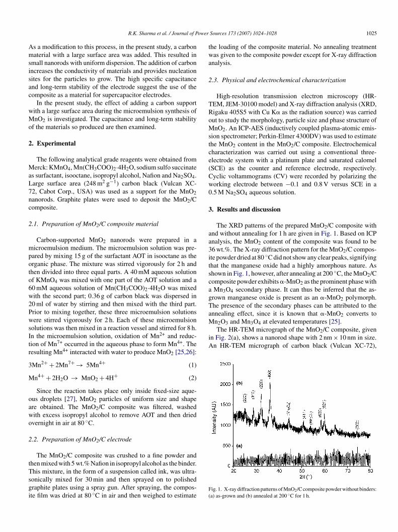
ower
Amsisac
wMo
2
MaL7nc
2
mpoto6w2PwsItr
3
M
oawo
2
tTsgi
twa
2
TRoMstce(Cw0
3
aa3itscagTaMn2O3 and Mn3O4 at elevated temperatures [25].
The HR-TEM micrograph of the MnO2/C composite, givenin Fig. 2(a), shows a nanorod shape with 2 nm × 10 nm in size.An HR-TEM micrograph of carbon black (Vulcan XC-72),
R.K. Sharma et al. / Journal of P
s a modification to this process, in the present study, a carbonaterial with a large surface area was added. This resulted in
mall nanorods with uniform dispersion. The addition of carbonncreases the conductivity of materials and provides nucleationites for the particles to grow. The high specific capacitancend long-term stability of the electrode suggest the use of theomposite as a material for supercapacitor electrodes.
In the present study, the effect of adding a carbon supportith a large surface area during the microemulsion synthesis ofnO2 is investigated. The capacitance and long-term stability
f the materials so produced are then examined.
. Experimental
The following analytical grade reagents were obtained fromerck: KMnO4, Mn(CH3COO)2·4H2O, sodium sulfo succinate
s surfactant, isooctane, isopropyl alcohol, Nafion and Na2SO4.arge surface area (248 m2 g−1) carbon black (Vulcan XC-2, Cabot Corp., USA) was used as a support for the MnO2anorods. Graphite plates were used to deposit the MnO2/Composite.
.1. Preparation of MnO2/C composite material
Carbon-supported MnO2 nanorods were prepared in aicroemulsion medium. The microemulsion solution was pre-
ared by mixing 15 g of the surfactant AOT in isooctane as therganic phase. The mixture was stirred vigorously for 2 h andhen divided into three equal parts. A 40 mM aqueous solutionf KMnO4 was mixed with one part of the AOT solution and a0 mM aqueous solution of Mn(CH3COO)2·4H2O was mixedith the second part; 0.36 g of carbon black was dispersed in0 ml of water by stirring and then mixed with the third part.rior to mixing together, these three microemulsion solutionsere stirred vigorously for 2 h. Each of these microemulsion
olutions was then mixed in a reaction vessel and stirred for 8 h.n the microemulsion solution, oxidation of Mn2+ and reduc-ion of Mn7+ occurred in the aqueous phase to form Mn4+. Theesulting Mn4+ interacted with water to produce MnO2 [25,26]:
Mn2+ + 2Mn7+ → 5Mn4+ (1)
n4+ + 2H2O → MnO2 + 4H+ (2)
Since the reaction takes place only inside fixed-size aque-us droplets [27], MnO2 particles of uniform size and shapere obtained. The MnO2/C composite was filtered, washedith excess isopropyl alcohol to remove AOT and then driedvernight in air at 80 ◦C.
.2. Preparation of MnO2/C electrode
The MnO2/C composite was crushed to a fine powder andhen mixed with 5 wt.% Nafion in isopropyl alcohol as the binder.
his mixture, in the form of a suspension called ink, was ultra-onically mixed for 30 min and then sprayed on to polishedraphite plates using a spray gun. After spraying, the compos-te film was dried at 80 ◦C in air and then weighed to estimateF(
Sources 173 (2007) 1024–1028 1025
he loading of the composite material. No annealing treatmentas given to the composite powder except for X-ray diffraction
nalysis.
.3. Physical and electrochemical characterization
High-resolution transmission electron microscopy (HR-EM, JEM-30100 model) and X-ray diffraction analysis (XRD,igaku 405S5 with Cu K� as the radiation source) was carriedut to study the morphology, particle size and phase structure ofnO2. An ICP-AES (inductively coupled plasma-atomic emis-
ion spectrometer; Perkin-Elmer 4300DV) was used to estimatehe MnO2 content in the MnO2/C composite. Electrochemicalharacterization was carried out using a conventional three-lectrode system with a platinum plate and saturated calomelSCE) as the counter and reference electrode, respectively.yclic voltammograms (CV) were recorded by polarizing theorking electrode between −0.1 and 0.8 V versus SCE in a.5 M Na2SO4 aqueous solution.
. Results and discussion
The XRD patterns of the prepared MnO2/C composite withnd without annealing for 1 h are given in Fig. 1. Based on ICPnalysis, the MnO2 content of the composite was found to be6 wt.%. The X-ray diffraction pattern for the MnO2/C compos-te powder dried at 80 ◦C did not show any clear peaks, signifyinghat the manganese oxide had a highly amorphous nature. Ashown in Fig. 1, however, after annealing at 200 ◦C, the MnO2/Composite powder exhibits �-MnO2 as the prominent phase withMn3O4 secondary phase. It can thus be inferred that the as-
rown manganese oxide is present as an �-MnO2 polymorph.he presence of the secondary phases can be attributed to thennealing effect, since it is known that �-MnO2 converts to
ig. 1. X-ray diffraction patterns of MnO2/C composite powder without binders:a) as-grown and (b) annealed at 200 ◦C for 1 h.

1026 R.K. Sharma et al. / Journal of Power Sources 173 (2007) 1024–1028
(left
FMcnM[sTfgfttscoM
btMecswcdth1tc0cohnn
itmeecori(tadmrsince at higher scan rates Na ions will only approach the outersurface of the electrode material. Hence the surface in the deeppores does not actively contribute to the capacitance. To evaluatethe rate capability of the composite electrode, cyclic voltammo-
Fig. 2. HR-TEM micrographs of (a) Vulcan XC-72 carbon
ig. 2(b), is also presented for comparison. Interestingly, thenO2 nanorods are distinct and dispersed uniformly over the
arbon surface with clear inter-particle boundaries. The MnO2anorods produced in the present study are smaller than thenO2 nanorods obtained by hydrothermal (50 nm × 2.5 �m)
28] or microemulsion (40–70 nm) [25] techniques. The presenttudy used a modified MnO2 microemulsion synthesis process.he carbon utilized in this process is thought to provide a surface
or the adsorption of nano-colloids and to thus prevent furtherrowth of MnO2 by agglomeration. The mechanism of MnO2ormation in a rod-type structure is not clearly understood. It ishought that MnO2, the reaction product of Mn(II) and Mn(VII),ends to agglomerate primarily due to the concentration and theurface energies. This rod type of 1D growth is preferred by theolloids under specific reaction conditions such as the presencef surfactant, the size of the aqueous (reactor) droplet and thenO2 concentration [28].The composite electrode material (MnO2/C) was tested
y cyclic voltammetry in a 0.5 M Na2SO4 solution ashe electrolyte. The weight ratio of electrode constituents,
nO2:C:Nafion, was 36:59:5. For comparison, a carbon blacklectrode with 5 wt.% binder was also studied. Fig. 3 showsyclic voltammograms recorded between −0.10 and 0.80 V ver-us SCE with and without adding MnO2 to the carbon supportith Nafion as the binder. As seen in the voltammograms, the
arbon acting as the support material for the MnO2 nanorodsoes not contribute much to the capacitance of composite elec-rode. The specific capacitance of carbon black (Vulcan XC-72)as been reported to be 27 F g−1 in a 1 M H2SO4 solution [4] and2.6 F g−1 in an organic solution of 1.0 M (C2H5)4NBF4 in ace-onitrile [29]. In the present investigation, it was found that theapacitance of carbon with 5 wt.% Nafion is about 6 F g−1 with.5 M Na2SO4 as the electrolyte. On the other hand, the MnO2/Composite electrode has a reasonably high specific capacitance
f 165 F g−1. After subtracting the contribution of the carbonost, a high pseudocapacitance of about 458 F g−1 for the MnO2anorods was calculated. Carbon black does not contribute sig-ificantly to the total capacitance of the electrode. Nevertheless,F(N
) and (b) MnO2/C composite with 36 wt.% MnO2 (right).
ts presence helps MnO2 nanorods to disperse over a large area,hereby increasing the active surface area of MnO2. Further-
ore, carbon black provides a low resistance path within thelectrode, and the pores of carbon black serve as reservoirs oflectrolyte that increase the ionic conductivity. In the MnO2/Composite electrode, a major part of the specific capacitanceriginates as pseudocapacitance from the Mn4+/Mn3+ reversibleedox process. This process is accompanied by the reversiblensertion and de-insertion of an alkali cation (Na+) or protonH+) present in the electrolyte [2,26,30]. It is generally notedhat, at low scan rates, the electrode material exhibits a rect-ngular CV shape, whereas at increasing scan rates, the shapeeforms due to slow diffusion of electrolyte ions within theatrix of the electrode material [31]. An increase in the scan
ate has a direct impact on the diffusion of Na+ into the matrix,+
ig. 3. Cyclic voltammograms of (a) MnO2/C composite and (b) carbon blackwith 5 wt.% Nafion) recorded between −0.1 and 0.8 V vs. SCE in 0.5 Ma2SO4, at a scan rate of 5 mV s−1.

R.K. Sharma et al. / Journal of Power
Fr1
gF
eioCip(p2(st
Fss
oc
icCTicrtt
4
MecpAgTctaMuc
R
ig. 4. Change in MnO2/C composite electrode capacitance at increasing scanates: (a) 5 mV s−1, (b) 25 mV s−1, (c) 50 mV s−1, (d) 75 mV s−1 and (e)00 mV s−1.
rams at different scan rates were recorded and are shown inig. 4.
Two mechanisms are proposed for charge storage in MnO2lectrodes. The first is based on the intercalation of H+ or Na+
ons in the electrode during reduction and oxidation [3,30]. Thether is based on the adsorption of Na+ ions on the electrode.ycling the composite electrode at high rates will hinder the Na+
ons reaching the outer surface which results in a decrease in theseudocapacitance. As seen in Fig. 4, with increasing scan rates5–100 mV s−1), the specific capacitance of a MnO2/C com-osite electrode decreases from 165 to 132 F g−1. This nearly
0% decrease in total available capacity at the high cycling rate100 mV s−1) essentially shows that the carbon support providesufficient surface area and porous channels for the transporta-ion of electrolyte ions. Therefore, even at high scan rates, mostig. 5. Life-cycle test of MnO2/C composite (1.2 mg cm−2) electrode. Insethows cyclic voltammograms for (a) first cycle and (b) after 10,000 cycles. Thecan rate is 50 mV s−1.
[[[[[[[
[
[[
[
[
Sources 173 (2007) 1024–1028 1027
f the material in the composite electrode is accessible and isontributing to the redox process.
The stability and reversibility of an electrode material aremportant for its use in an electrochemical supercapacitor. Theomposite electrode (36 wt.% MnO2) was subjected to 10,000V cycles in the voltage range of −0.1 to 0.8 V at 50 mV s−1.he variation of electrode capacitance as a function of CV cycles
s shown in Fig. 5. There is only a 3% decay in the availableapacity over 10,000 cycles. This implies an excellent long-termecycling capability. Furthermore, as shown in the inset of Fig. 5,he shape of the voltammograms after 10,000 cycles confirmshe highly reversible nature of the electrode material.
. Conclusions
A microemulsion growth process to create nano-structurednO2/C composites for use as a highly capacitive and reversible
lectrode material is reported. Distinct nanorods of MnO2, withontrolled particle dimensions (2 nm × 10 nm) and uniform dis-ersion, have been obtained on carbon with a large surface area.n important finding is that the addition of carbon black duringrowth yields smaller and uniformly dispersed MnO2 nanorods.he MnO2/C composite exhibits a high capacitance and a longycle-life with perfect reversibility. The specific capacitance ofhe MnO2/C composite electrode in 0.5 M Na2SO4 is 165 F g−1
nd that of MnO2 is 458 F g−1. Based on cycle-life tests, thenO2/C composite electrode has a highly stable performance
p to 10,000 cycles. The long-term stability of the MnO2/Composite electrode supports its use in supercapacitor devices.
eferences
[1] B.E. Conway, Electrochemical Capacitors: Scientific Fundamentals andTechnological Applications, Kluwer Academic/Plenum Press, New York,1999.
[2] M. Toupin, T. Brousse, D. Belanger, Chem. Mater. 16 (2004) 3184–3190.[3] M. Toupin, T. Brousse, D. Belanger, Chem. Mater. 14 (2002) 3946–3952.[4] H. Kim, B.N. Popov, J. Power Sources 104 (2002) 52–61.[5] J.P. Zheng, P.J. Cyjan, T.R. Jow, J. Electrochem. Soc. 142 (1995)
2699–2703.[6] C.C. Hu, T.W. Tsou, J. Power Sources 115 (2003) 179–186.[7] H. Kim, B.N. Popov, J. Electrochem. Soc. 150 (2003) D56–D62.[8] E.R. Pinero, V.E. Khomenko, F.E. Beguin, J. Electrochem. Soc. 152 (2005)
A229–A235.[9] K.R. Prasad, N. Miura, J. Power Sources 135 (2004) 354–360.10] K.R. Prasad, N. Miura, Electrochem. Commun. 6 (2004) 1004–1008.11] S.L. Kuo, N.L. Wu, J. Power Sources 162 (2006) 1437–1443.12] X. Liu, S. Fu, C. Huang, Powder Technol. 154 (2005) 120–124.13] Y. Xiong, Y. Xie, Z. Li, C. Wu, Chem. Eur. J. 9 (2003) 1645–1651.14] F. Cheng, J. Chen, X. Gou, P. Shen, Adv. Mater. 17 (2005) 2753–2756.15] F.A. Al-Sagheer, M.I. Zaki, Colloids Surf. A 173 (2000) 193–204.16] S. Devaraj, N. Munichandraiah, Electrochem. Solid State Lett. 8 (2005)
A373–A377.17] V. Subramanian, H. Zhu, R. Vajtai, P.M. Ajayan, B. Wei, J. Phys. Chem. B
109 (2005) 20207–20214.18] X. Wang, Y.D. Li, Chem. Commun. 124 (2002) 764–765.19] M. Wei, Y. Konishi, H. Zhou, H. Sugihara, H. Arakawa, Nanotechnology
16 (2005) 245–249.20] D. Zheng, S. Sun, W. Fan, H. Yu, C. Fan, G. Cao, Z. Yin, X. Song, J. Phys.
Chem. B 109 (2005) 16439–16443.21] X. Dong, W. Shen, J. Gu, L. Xiong, Y. Zhu, Hua Li, J. Shi, J. Phys. Chem.
B 110 (2006) 6015–6019.

1 ower
[
[
[
[
[
[
[
028 R.K. Sharma et al. / Journal of P
22] V. Subramanian, H. Zhu, B. Wei, Electrochem. Commun. 8 (2006)827–832.
23] J.K. Chang, C.T. Lin, W.T. Tsai, Electrochem. Commun. 6 (2004) 666–671.
24] S. Bach, M. Henry, N. Baffer, J. Livage, J. Solid State Chem. 88 (1990)325–333.
25] S. Devavraj, N. Munichandraiah, J. Electrochem. Soc. 154 (2007)A80–A88.
26] H.Y. Lee, J.B. Goodenough, J. Solid State Chem. 144 (1999) 220–223.
[[
[
Sources 173 (2007) 1024–1028
27] B.L. Cushing, V.L. Kolesnichenko, C.J. O’Connor, Chem. Rev. (Washing-ton, DC) 104 (2004) 3893–3946.
28] H. Wang, D. Qian, Z. Lu, Y. Li, R. Cheng, W. Zhang, J. Crystal Growth, inpress.
29] O. Barbieri, M. Hahn, A. Herzog, R. Kotz, Carbon 43 (2005) 1303–1310.30] S.C. Pang, M.A. Anderson, T.W. Chapman, J. Electrochem. Soc. 147 (2000)
444–450.31] S. Sarangapani, B.V. Tilak, C.P. Chen, J. Electrochem. Soc. 143 (1996)
3791–3799.