carbon storage - national energy technology laboratory€¦ · the overall objective of the u.s....
TRANSCRIPT

TECHNOLOGY PROGRAM PLAN
SEPTEMBER 2013
CARBON STORAGE

U.S. DEPARTMENT OF ENERGY
TECHNOLOGY PROGRAM PLAN
PREf
ACE
ii
DISCLAIMERThis report was prepared as an account of work sponsored by an agency of the United States Government. Neither the United States Government nor any agency thereof, nor any of their employees, makes any warranty, express or implied, or assumes any legal liability or responsibility for the accuracy, completeness, or usefulness of any information, apparatus, product, or process disclosed, or represents that its use would not infringe privately owned rights. Reference therein to any specific commercial product, process, or service by trade name, trademark, manufacturer, or otherwise does not necessarily constitute or imply its endorsement, recommendation, or favoring by the United States Government or any agency thereof. The views and opinions of authors expressed therein do not necessarily state or reflect those of the United States Government or any agency thereof.

CARBON STORAGE
NATIONAL ENERGY TECHNOLOGY LABORATORY
THIS PAGE INTENTIONALLY LEFT BLANK
PREfACE
iii
U.S. DEPARTMENT OF ENERGY
TECHNOLOGY PROGRAM PLAN
TABL
E O
f CO
NTE
NTS
iv
TABLE OF CONTENTS
E X E C U T I V E S U M M A R Y . . . . . . . . . . . . . . . . . . . . . . . . . . . . . . . . . . . . . . . . . . . . . . . . . . . . . . . . . . . . . . . . . . . . . . . . . . . . . . . . . . . . . . . . . . . . . . . . . . . . . . . . 2
C H A P T E R 1: O V E R V I E W . . . . . . . . . . . . . . . . . . . . . . . . . . . . . . . . . . . . . . . . . . . . . . . . . . . . . . . . . . . . . . . . . . . . . . . . . . . . . . . . . . . . . . . . . . . . . . . . . . . . . . . 61.1 Introduction ..................................................................................................................................................................................................................... 71.2 CCS and Power Systems Program Area ............................................................................................................................................................................ 81.3 Carbon Storage Program ................................................................................................................................................................................................11
1.3.1 Background ........................................................................................................................................................................................................111.3.2 Recent R&D Activities .........................................................................................................................................................................................13
1.4 RD&D Stages, Technology Readiness Levels, and Project Cost Estimation ......................................................................................................................141.4.1 RD&D Stages .......................................................................................................................................................................................................141.4.2 Technology Readiness Levels ..............................................................................................................................................................................141.4.3 RD&D Project Cost Estimation ............................................................................................................................................................................17
C H A P T E R 2 : G O A L S A N D B E N E F I T S . . . . . . . . . . . . . . . . . . . . . . . . . . . . . . . . . . . . . . . . . . . . . . . . . . . . . . . . . . . . . . . . . . . . . . . . . . . . . . . . . . . . 182.1 Goals ...............................................................................................................................................................................................................................19
2.1.1 CCRP Goals ..........................................................................................................................................................................................................192.1.2 Carbon Storage Program Goals ..........................................................................................................................................................................19
2.2 Carbon Storage Program Benefits ................................................................................................................................................................................. 202.2.1 Economic, Technical, and Environmental Benefits ............................................................................................................................................ 20
C H A P T E R 3: T E C H N I C A L P L A N . . . . . . . . . . . . . . . . . . . . . . . . . . . . . . . . . . . . . . . . . . . . . . . . . . . . . . . . . . . . . . . . . . . . . . . . . . . . . . . . . . . . . . . . . . . 223.1 Geologic Storage Technologies and Simulation and Risk Assessment (Core R&D) ......................................................................................................... 23
3.1.1 Background/Technical Discussion ...................................................................................................................................................................... 233.1.2 GSRA R&D Approach ...........................................................................................................................................................................................243.1.3 Key Technologies and Research Timeline........................................................................................................................................................... 25
3.2 Monitoring, Verification, Accounting (MVA), and Assessment (Core R&D) ..................................................................................................................... 283.2.1 Background/Technical Discussion ..................................................................................................................................................................... 283.2.2 MVA R&D Approach ........................................................................................................................................................................................... 293.2.3 Key Technologies and Research Timeline .......................................................................................................................................................... 30
3.3 Carbon Use and Reuse (Core R&D) ................................................................................................................................................................................. 333.3.1 Background/Technical Discussion ...................................................................................................................................................................... 333.3.2 Carbon Use and Reuse R&D Approach ............................................................................................................................................................... 333.3.3 Key Technologies and Research Timeline .......................................................................................................................................................... 34
3.4 Infrastructure (Regional Carbon Sequestration Partnerships) ....................................................................................................................................... 363.4.1 Background/Technical Discussion ...................................................................................................................................................................... 363.4.2 Infrastructure Key Technologies R&D Approach ................................................................................................................................................ 383.4.3 Supporting Activities ......................................................................................................................................................................................... 443.4.4 Technology Timeline ......................................................................................................................................................................................... 48
C H A P T E R 4 : P R O G R A M S U P P O R T E L E M E N T S . . . . . . . . . . . . . . . . . . . . . . . . . . . . . . . . . . . . . . . . . . . . . . . . . . . . . . . . . . . . . . . . . . . . . . 504.1 Coordination with Other Elements ................................................................................................................................................................................ 51
4.1.1 Focus Area for Sequestration Science................................................................................................................................................................. 514.1.2 Global Collaborations ........................................................................................................................................................................................ 534.1.3 Additional Supporting Elements ....................................................................................................................................................................... 56
A B B R E V I AT I O N S . . . . . . . . . . . . . . . . . . . . . . . . . . . . . . . . . . . . . . . . . . . . . . . . . . . . . . . . . . . . . . . . . . . . . . . . . . . . . . . . . . . . . . . . . . . . . . . . . . . . . . . . . . . . . . . 58
F O R M O R E I N F O R M AT I O N . . . . . . . . . . . . . . . . . . . . . . . . . . . . . . . . . . . . . . . . . . . . . . . . . . . . . . . . . . . . . . . . . . . . . . . . . . . . . . . . . . . . . . . . . . . . . . . . . 6 0
CARBON STORAGE
NATIONAL ENERGY TECHNOLOGY LABORATORYTA
BLE Of CO
NTEN
TS
v
LIST OF TABLESTable 3-1. GSRA Key Technologies Research Description . . . . . . . . . . . . . . . . . . . . . . . . . . . . . . . . . . . . . . . . . . . . . . . . . . . . . . . . . . . . . . . . . . . . . . . . . . . . . . . . . . . . . . . . . . . . . . . . . . . . . . . . . . . . . . . . . . . . . . . . . . . . . 25Table 3-2. MVA Key Technologies Research Description . . . . . . . . . . . . . . . . . . . . . . . . . . . . . . . . . . . . . . . . . . . . . . . . . . . . . . . . . . . . . . . . . . . . . . . . . . . . . . . . . . . . . . . . . . . . . . . . . . . . . . . . . . . . . . . . . . . . . . . . . . . . . . 30Table 3-3. Carbon Use and Reuse Key Technologies Research Description . . . . . . . . . . . . . . . . . . . . . . . . . . . . . . . . . . . . . . . . . . . . . . . . . . . . . . . . . . . . . . . . . . . . . . . . . . . . . . . . . . . . . . . . . . . . . . . . . . . . . . . . 35Table 3-4. Matrix of Field Activities in Different Reservoir Classes (2012) . . . . . . . . . . . . . . . . . . . . . . . . . . . . . . . . . . . . . . . . . . . . . . . . . . . . . . . . . . . . . . . . . . . . . . . . . . . . . . . . . . . . . . . . . . . . . . . . . . . . . . . . . 39Table 3-5. Small-Scale CO2 Injection Project Details . . . . . . . . . . . . . . . . . . . . . . . . . . . . . . . . . . . . . . . . . . . . . . . . . . . . . . . . . . . . . . . . . . . . . . . . . . . . . . . . . . . . . . . . . . . . . . . . . . . . . . . . . . . . . . . . . . . . . . . . . . . . . . . . . . . 41Table 3-6. Large-Scale CO2 Injection Project Details . . . . . . . . . . . . . . . . . . . . . . . . . . . . . . . . . . . . . . . . . . . . . . . . . . . . . . . . . . . . . . . . . . . . . . . . . . . . . . . . . . . . . . . . . . . . . . . . . . . . . . . . . . . . . . . . . . . . . . . . . . . . . . . . . . 43Table 3-7. DOE Best Practice Manuals and Descriptions . . . . . . . . . . . . . . . . . . . . . . . . . . . . . . . . . . . . . . . . . . . . . . . . . . . . . . . . . . . . . . . . . . . . . . . . . . . . . . . . . . . . . . . . . . . . . . . . . . . . . . . . . . . . . . . . . . . . . . . . . . . . . . 47
Table 4-1. DOE Support to International CCS Projects . . . . . . . . . . . . . . . . . . . . . . . . . . . . . . . . . . . . . . . . . . . . . . . . . . . . . . . . . . . . . . . . . . . . . . . . . . . . . . . . . . . . . . . . . . . . . . . . . . . . . . . . . . . . . . . . . . . . . . . . . . . . . . . . . 54
LIST OF FIGURESFigure 1-1. CCS and Power Systems Subprograms . . . . . . . . . . . . . . . . . . . . . . . . . . . . . . . . . . . . . . . . . . . . . . . . . . . . . . . . . . . . . . . . . . . . . . . . . . . . . . . . . . . . . . . . . . . . . . . . . . . . . . . . . . . . . . . . . . . . . . . . . . . . . . . . . . . . . . 9Figure 1-2. CCS Technology Category Definitions . . . . . . . . . . . . . . . . . . . . . . . . . . . . . . . . . . . . . . . . . . . . . . . . . . . . . . . . . . . . . . . . . . . . . . . . . . . . . . . . . . . . . . . . . . . . . . . . . . . . . . . . . . . . . . . . . . . . . . . . . . . . . . . . . . . . . . 10Figure 1-3. Carbon Storage Program Structure . . . . . . . . . . . . . . . . . . . . . . . . . . . . . . . . . . . . . . . . . . . . . . . . . . . . . . . . . . . . . . . . . . . . . . . . . . . . . . . . . . . . . . . . . . . . . . . . . . . . . . . . . . . . . . . . . . . . . . . . . . . . . . . . . . . . . . . . 12Figure 1-4. Summary of Characteristics at Different Development Scales . . . . . . . . . . . . . . . . . . . . . . . . . . . . . . . . . . . . . . . . . . . . . . . . . . . . . . . . . . . . . . . . . . . . . . . . . . . . . . . . . . . . . . . . . . . . . . . . . . . . . . . . 14Figure 1-5. Technology Readiness Level—Relationship to Scale, Degree of Integration, and Test Environment . . . . . . . . . . . . . . . . . . . . . . . . . . . . . . . . . . . . . . . . . . . . . . . . . . . . . . . . . 15Figure 1-6. Schematic of the TRL Concept . . . . . . . . . . . . . . . . . . . . . . . . . . . . . . . . . . . . . . . . . . . . . . . . . . . . . . . . . . . . . . . . . . . . . . . . . . . . . . . . . . . . . . . . . . . . . . . . . . . . . . . . . . . . . . . . . . . . . . . . . . . . . . . . . . . . . . . . . . . . . . 16Figure 1-7. Representative Timing and Cost for Technology Component Development . . . . . . . . . . . . . . . . . . . . . . . . . . . . . . . . . . . . . . . . . . . . . . . . . . . . . . . . . . . . . . . . . . . . . . . . . . . . . . . . . . . . . . . . 17
Figure 2-1. Schematic of Carbon Storage Program RD&D Efforts, Goals, and Possible Benefits of the R&D . . . . . . . . . . . . . . . . . . . . . . . . . . . . . . . . . . . . . . . . . . . . . . . . . . . . . . . . . . . . . . . . . 20
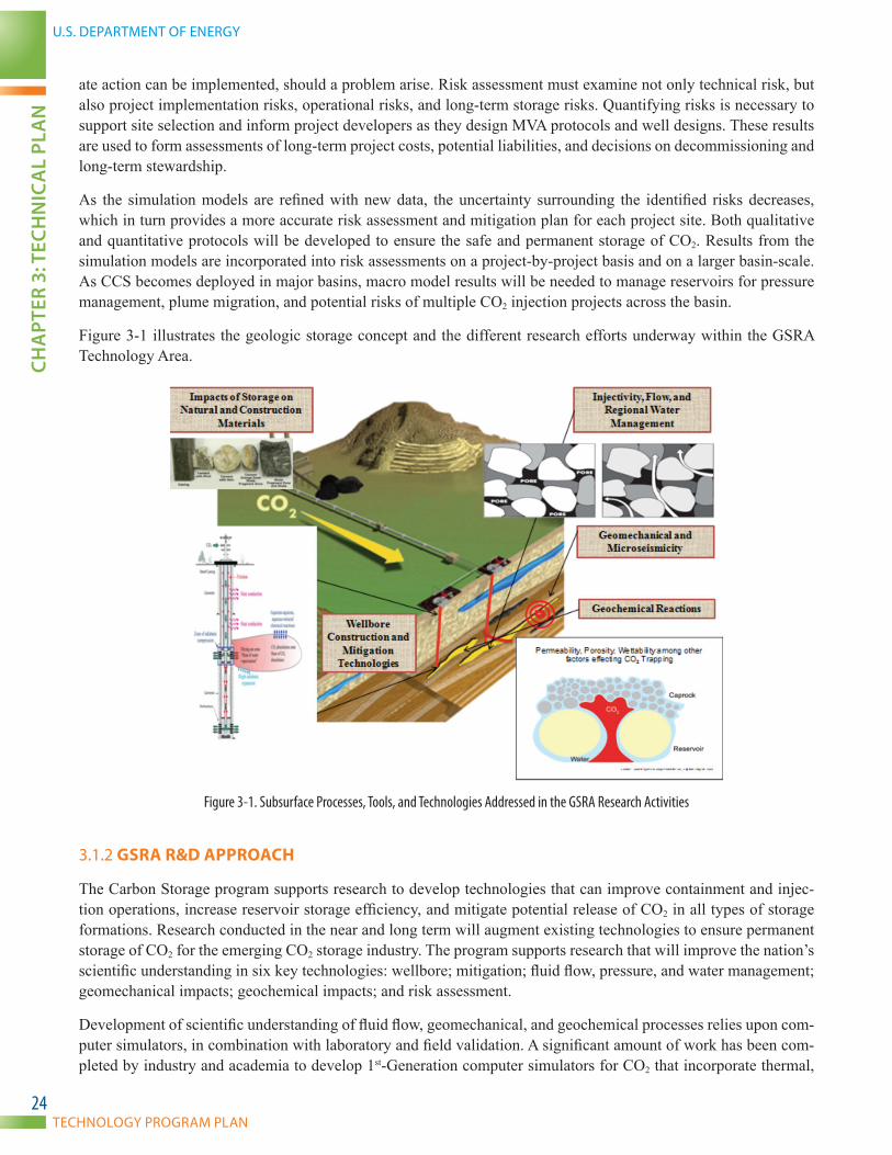
Figure 3-1. Subsurface Processes, Tools, and Technologies Addressed in the GSRA Research Activities . . . . . . . . . . . . . . . . . . . . . . . . . . . . . . . . . . . . . . . . . . . . . . . . . . . . . . . . . . . . . . . . . . . . . 24Figure 3-2. Research Timeline for GSRA . . . . . . . . . . . . . . . . . . . . . . . . . . . . . . . . . . . . . . . . . . . . . . . . . . . . . . . . . . . . . . . . . . . . . . . . . . . . . . . . . . . . . . . . . . . . . . . . . . . . . . . . . . . . . . . . . . . . . . . . . . . . . . . . . . . . . . . . . . . . . . . . . 26Figure 3-3. MVA Tools Available for Monitoring CCS Projects. . . . . . . . . . . . . . . . . . . . . . . . . . . . . . . . . . . . . . . . . . . . . . . . . . . . . . . . . . . . . . . . . . . . . . . . . . . . . . . . . . . . . . . . . . . . . . . . . . . . . . . . . . . . . . . . . . . . . . . . 30Figure 3-4. Research Timeline for MVA . . . . . . . . . . . . . . . . . . . . . . . . . . . . . . . . . . . . . . . . . . . . . . . . . . . . . . . . . . . . . . . . . . . . . . . . . . . . . . . . . . . . . . . . . . . . . . . . . . . . . . . . . . . . . . . . . . . . . . . . . . . . . . . . . . . . . . . . . . . . . . . . . . 31Figure 3-5. Opportunities for Carbon Use and Reuse . . . . . . . . . . . . . . . . . . . . . . . . . . . . . . . . . . . . . . . . . . . . . . . . . . . . . . . . . . . . . . . . . . . . . . . . . . . . . . . . . . . . . . . . . . . . . . . . . . . . . . . . . . . . . . . . . . . . . . . . . . . . . . . . . 34Figure 3-6. Research Timeline for Carbon Use and Reuse . . . . . . . . . . . . . . . . . . . . . . . . . . . . . . . . . . . . . . . . . . . . . . . . . . . . . . . . . . . . . . . . . . . . . . . . . . . . . . . . . . . . . . . . . . . . . . . . . . . . . . . . . . . . . . . . . . . . . . . . . . . . 35Figure 3-7. Regional Carbon Sequestration Partnership Regions . . . . . . . . . . . . . . . . . . . . . . . . . . . . . . . . . . . . . . . . . . . . . . . . . . . . . . . . . . . . . . . . . . . . . . . . . . . . . . . . . . . . . . . . . . . . . . . . . . . . . . . . . . . . . . . . . . . 37Figure 3-8. Small-Scale CO2 Injection Projects Map . . . . . . . . . . . . . . . . . . . . . . . . . . . . . . . . . . . . . . . . . . . . . . . . . . . . . . . . . . . . . . . . . . . . . . . . . . . . . . . . . . . . . . . . . . . . . . . . . . . . . . . . . . . . . . . . . . . . . . . . . . . . . . . . . . . 40Figure 3-9. Large-Scale CO2 Injection Projects Map . . . . . . . . . . . . . . . . . . . . . . . . . . . . . . . . . . . . . . . . . . . . . . . . . . . . . . . . . . . . . . . . . . . . . . . . . . . . . . . . . . . . . . . . . . . . . . . . . . . . . . . . . . . . . . . . . . . . . . . . . . . . . . . . . . . 42Figure 3-10. NATCARB Schematic . . . . . . . . . . . . . . . . . . . . . . . . . . . . . . . . . . . . . . . . . . . . . . . . . . . . . . . . . . . . . . . . . . . . . . . . . . . . . . . . . . . . . . . . . . . . . . . . . . . . . . . . . . . . . . . . . . . . . . . . . . . . . . . . . . . . . . . . . . . . . . . . . . . . . . . . . 44Figure 3-11. Atlas IV Estimates of CO2 Stationary Source Emissions and Estimates of CO2 Storage Resources for Geologic Storage Sites . . . . . . . . . . . . . . . . . . . . . . . . . . . . . . 46Figure 3-12. Research Timeline for the Regional Carbon Sequestration Partnerships (Infrastructure) . . . . . . . . . . . . . . . . . . . . . . . . . . . . . . . . . . . . . . . . . . . . . . . . . . . . . . . . . . . . . . . . . . . . . . 49
Figure 4-1. Energy Data eXchange Website . . . . . . . . . . . . . . . . . . . . . . . . . . . . . . . . . . . . . . . . . . . . . . . . . . . . . . . . . . . . . . . . . . . . . . . . . . . . . . . . . . . . . . . . . . . . . . . . . . . . . . . . . . . . . . . . . . . . . . . . . . . . . . . . . . . . . . . . . . . . . 53
U.S. DEPARTMENT OF ENERGY
TECHNOLOGY PROGRAM PLAN
EXEC
UTI
VE
SUM
MA
RY
2
EXECUTIVE SUMMARY
Carbon capture and storage (CCS) consists of a suite of technologies that can benefit an array of industries, includ-ing power plants (fossil, biofuel, and geothermal), refineries, natural gas processing plants, and other industrial sources. CCS involves capture of carbon dioxide (CO2) at large power generating and industrial facilities, compres-sion and transport by pipeline, and injection into the deep subsurface for permanent storage. For more than 20 years, scientists have been investigating CCS as one option for the mitigation of CO2 emissions. During the past decade, CCS has gained considerable recognition among the broader global scientific community, as well as policymakers, as a promising option to reduce greenhouse gas (GHG) emissions. The United Nations’ Intergovernmental Panel on Climate Change (a Nobel Prize winning organization) concluded in its Fourth Assessment Report on climate change1 that CCS was a technology with the potential for important contributions to the mitigation of GHG emis-sions by 2030. The report listed CCS as a key technology for mitigation in both the energy and industrial sectors. In 2008 in Tokyo, Japan, the G-8 leaders stated: “We strongly support the launching of 20 large-scale CCS demonstra-tion projects globally by 2010, taking into account various national circumstances, with a view to beginning broad deployment of CCS by 2020.”
In addition, in February 2010, 14 Executive departments and Federal agencies established an Interagency Task Force on CCS. On August 12, 2010, the Task Force delivered a series of recommendations on overcoming the bar-riers to the widespread, cost-effective deployment of CCS within 10 years. The report concludes that CCS can play an important role in domestic GHG emissions reductions while preserving the option of using abundant domestic energy resources. However, widespread, cost-effective deployment of CCS will occur only if the technology is commercially available at economically competitive prices and supportive national policy frameworks are in place. The purpose of the Carbon Storage Technology Program Plan is to:
• Support the findings of the CCS Task Force to develop cost-effective technologies to ensure safe, publically acceptable CO2 storage while meeting regulatory requirements.
• Ensure advanced technologies are available by 2020 for first mover projects. First mover projects include early commercial-scale projects in depleted oil reservoirs and saline formations, deployed with economic benefits that offset the cost of capture.
• Ensure advanced technologies are available by 2030 to support broad deployment projects. Broad deployment projects include next-generation commercial-scale projects in all storage types with an emphasis on saline formations.
The future role of CCS in an “all-of-the-above” energy strategy will require that industry continue to consider CCS as a key technology in its carbon management portfolio. A balance is needed between energy security and increas-ing concerns over the impacts of increasing concentrations of GHGs in the atmosphere. At present, approximately one-third of the CO2 emissions in the United States come from power plants. Other industrial facilities contribute approximately one-third of the remaining emissions. The opportunity to apply CCS to these facilities will have significant benefits for the U.S. economy and environment.
The overall objective of the U.S. Department of Energy’s (DOE) Carbon Storage program is to develop and advance CCS technologies both onshore and offshore that will significantly improve the effectiveness of the technology, re-duce the cost of implementation, and be ready for widespread commercial deployment in the 2025–2035 timeframe. To accomplish widespread deployment, technical and economic barriers must be addressed and data and information generated and communicated to inform regulators and industry on the safety and permanence of CCS. Four program goals have been established that support the scaleup and development of CCS leading to widespread deployment.
1 IPCC 2007
CARBON STORAGE
NATIONAL ENERGY TECHNOLOGY LABORATORYEXECU
TIVE SU
MM
ARY
3
• Develop and validate technologies to ensure 99 percent storage permanence.
• Develop technologies to improve reservoir storage efficiency while ensuring containment effectiveness.
• Support industry’s ability to predict CO2 storage capacity in geologic formations to within ±30 percent.
• Develop Best Practice Manuals for monitoring, verification, accounting (MVA), and assessment; site screening, selection, and initial characterization; public outreach; well management activities; and risk analysis and simulation.
Since 1997, DOE’s Carbon Storage program has significantly advanced the CCS knowledge base in selected Tech-nology Areas through a diverse portfolio of applied research projects. The portfolio includes industry cost-shared technology development projects, university research grants, collaborative work with other national laboratories, and research conducted in-house through the National Energy Technology Laboratory’s (NETL) Office of Research and Development. The Carbon Storage program contains three principal components: Core Research and Develop-ment (R&D); the Regional Carbon Sequestration Partnerships (RCSPs) (Infrastructure); and Supporting Activities. The integration of these components will address technological and marketplace challenges, as described below:
► CORE R&D—Core R&D involves both applied laboratory- and pilot-scale research focused on developing new technologies and systems for geologic storage. Core R&D encompasses three Technology Areas: (1) Geologic Storage Technologies and Simulation and Risk Assessment; (2) Monitoring, Verification, Ac-counting (MVA), and Assessment; and (3) Carbon Use and Reuse.
In October 2011, DOE’s NETL held a stakeholder workshop titled, Storage in Saline Formations R&D Workshop, to seek input from stakeholders on CCS research priorities. The results of this workshop have helped to shape the research focus of the CCS program’s activities on the first two key technologies and have been integrated into this technology program plan.
For the Carbon Use and Reuse Technology Area, the objective of the research is to boost the commodity market for CO2. The metric is to develop utilization technologies that cost less than $10 per metric ton of CO2 while making no additional contribution to CO2 emissions. The concept of converting CO2 into a valued prod-uct and commodity, and possibly accelerating the implementation of CCS, has attracted interest worldwide.
► INfRASTRUCTURE (RCSPS AND OTHER SMALL- AND LARGE-SCALE PROJECTS)—The Infrastructure component includes the seven Regional Carbon Sequestration Partnerships, site characterization projects, small-scale field projects, and large-scale field projects conducted both onshore and offshore. The majority of the Infrastructure effort is conducted by the RCSP network to help develop the technology, infrastructure, and regulations to implement large-scale CO2 storage regionally within various depositional environments. The RCSPs’ research effort is carrying out regional characterization and small- and large-scale field projects to demonstrate that different types of geologic storage reservoirs, distributed over different geographic regions of the United States, have the capability to permanently and safely store CO2, providing the basis for com-mercial-scale CO2 storage. RCSP field projects involve integrated system testing and validation of geologic storage, simulation, and risk assessment; and MVA technologies in different depositional environments. DOE acknowledges that offshore CCS offers promising opportunities due to several key advantages. For example:
• Offshore storage provides significant additional CO2 storage potential, particularly in brine-filled formations and mature or depleted petroleum reservoirs.
• The formation fluid in offshore sediments is typically similar to seawater in terms of chemistry and salinity.

U.S. DEPARTMENT OF ENERGY
TECHNOLOGY PROGRAM PLAN
EXEC
UTI
VE
SUM
MA
RY
4
• Locating storage sites away from heavily populated, onshore areas avoids the concern of storing CO2 beneath a populated area. This also reduces the difficulty of establishing surface and mineral rights at candidate storage sites.
• Offshore CCS provides storage sites in the vicinity of many large emission sources along U.S. coastlines.
► SUPPORTING ACTIVITIES—Supporting Activities contribute to an integrated approach to ensure CCS technologies are cost-effective and commercially available. The program relies on NETL’s Office of Re-search and Development and the national laboratory network to complement the program approach to reducing CO2 emissions. NETL’s Office of Research and Development provides DOE’s Fossil Energy Research and Development program an onsite location, where fundamental and applied fossil energy R&D is performed by Government engineers and scientists. In addition, NETL’s Office of Research and Devel-opment offers a venue for participation in collaborative research and provides an evaluation of new tech-nology concepts, products, and materials. The program also relies on international collaborations. DOE is partnering with several international organizations, such as the International Energy Agency’s Greenhouse Gas R&D Programme, the Carbon Sequestration Leadership Forum, and the North American Carbon Atlas Partnership. DOE is also directly engaged in a number of large-scale CCS demonstration projects around the world, spanning five continents.
REGULATORY DRIVERS FOR CARBON STORAGE TECHNOLOGY DEVELOPMENT
In November 2010, the U.S. Environmental Protection Agency (EPA) finalized requirements for geologic storage of CO2, including the development of a new class of wells, Class VI, under the authority of the Safe Drinking Water Act’s Underground Injection Control program. These requirements, also known as the Class VI rule, are designed to protect underground sources of drinking water and to ensure safe, permanent CO2 storage. The Class VI rule builds on existing Underground Injection Control program requirements, with extensive tailored requirements that address CO2 injection for long-term storage to ensure that wells used for geologic storage are appropriately sited, constructed, tested, monitored, funded, and closed. The rule also affords owners or operators injection depth flex-ibility to address injection in various geologic settings in the United States in which geologic storage may occur, including deep saline formations and oil- and gasfields that are transitioned for use as CO2 storage sites.
In a separate, yet complimentary, rulemaking under authority of the Clean Air Act, the EPA has finalized reporting requirements under the GHG reporting program for facilities that inject CO2 underground for geologic storage (Sub-part RR) and all other facilities that inject CO2 underground (Subpart UU). Information obtained under the GHG reporting program will enable the EPA to track the amount of CO2 received by these facilities.
Over the last several years, a number of U.S. States have also begun to implement rules that govern the injection of CO2 within their borders. These U.S. States have enacted elements of legal frameworks for CCS. These elements include comprehensive State frameworks for regulating pore space ownership, eminent domain for CO2 pipelines, facility performance standards, portfolio standards, and a fund for administering State activities on CCS.
There are specific issues associated with CO2 storage and hydrocarbon recovery that will need to be resolved as these regulations are implemented. These issues include: assessment of the potential risk posed by existing wells and the need for new methods to upgrade old wells and to remediate those that cannot be upgraded. There is ad-ditional complexity in modeling and monitoring for CO2 in the reservoir resulting from the presence of oil with multiple fluids such as natural gas, brine, and CO2. Optimization of those reservoirs for both CO2 storage capacity and hydrocarbon production is required. The different fluid phases in hydrocarbon reservoirs influence which subset of monitoring methods is best suited for various geologic depositional environments in association with active hy-drocarbon recovery. The activities of the Carbon Storage program directly support industry’s ability to comply with regulations as well as the regulatory community’s development of CCS rules and reporting guidelines.

CARBON STORAGE
NATIONAL ENERGY TECHNOLOGY LABORATORYEXECU
TIVE SU
MM
ARY
5
CCS and other clean coal technologies can play a critical role in mitigating CO2 emissions while supporting energy security in the United States. DOE’s Carbon Storage program has positioned the United States on a path toward ensuring that the enabling technologies will be available to address the demands of new regulations and affect first mover and broad deployment CCS projects in the 2020–2030 timeframe. Continued U.S. leadership in technology development and future deployment is important to the cultivation of economic rewards and new business opportu-nities, both domestically and abroad.

U.S. DEPARTMENT OF ENERGY
TECHNOLOGY PROGRAM PLAN
CHA
PTER
1: O
VER
VIE
w
6
CHAPTER 1: OVERVIEW
CARBON STORAGE
NATIONAL ENERGY TECHNOLOGY LABORATORYCH
APTER 1: O
VERV
IEw
7
1.1 INTRODUCTION
During the past decade, carbon capture and storage (CCS) has gained considerable recognition and support among the broader global scientific community, as well as policymakers, as one option to reduce greenhouse gas (GHG) emissions. The United Nations’ Intergovernmental Panel on Climate Change (IPCC) (a Nobel Prize winning organi-zation) concluded in its Fourth Assessment Report on climate change (IPCC 2007) that CCS was a technology with the potential for important contributions to GHG mitigation by 2030. The report listed CCS as a key technology for GHG mitigation in both the energy and industrial sectors. In 2008 in Tokyo (Japan), the G-8 leaders stated: “We strongly support the launching of 20 large-scale CCS demonstration projects globally by 2010, taking into account various national circumstances, with a view to beginning broad deployment of CCS by 2020.”
During the past decade CCS has also gained great momentum with billions of dollars committed worldwide to research, development, and demonstration (RD&D) projects in an effort to prove and improve the technology in time for full-scale commercial use. Although carbon dioxide (CO2) injection has been used for enhanced oil recov-ery (EOR) and enhanced gas recovery for decades, permanent geological storage integrated with power plants and industrial facilities is considered to be emerging technology. Most experts agree that CCS must be successfully demonstrated at commercial scale in various geological formations and geographic regions before the technology is considered commercially ready for wide-scale deployment.
The U.S. Department of Energy (DOE) has been a world leader in this effort. A key element of the National Energy Technology Laboratory (NETL)-managed Carbon Storage program is the Regional Carbon Sequestration Partner-ship (RCSP) Initiative, which comprises seven partnerships spanning 43 U.S. States and 4 Canadian Provinces. This initiative includes field tests throughout the United States to fully characterize geologic storage sites, validate models, validate prior findings, and develop measurement, verification, accounting (MVA), and assessment instru-mentation. The field-scale investigations underway as part of the RCSP Initiative will provide direct observations on the behavior of CO2 underground, building confidence that CO2 can be injected and stored safely. In fact, in 2008 and again in 2011, an International Energy Agency Greenhouse Gas (IEAGHG) R&D Programme expert review panel peer reviewed the Carbon Storage program, stating that the RCSPs’ Development Phase is an “excellent pro-gram that will achieve significant results for development of CCS in the United States, Canada, and internationally.”
DOE/NETL has also initiated a comprehensive effort on risk assessment of CCS, the National Risk Assessment Program (NRAP), to utilize these investigations (along with a strong science base) to develop a sound framework for ensuring that each specific storage site is properly chosen and developed for safe, long-term storage. In addition, DOE/NETL has initiated several commercial demonstration projects under the Clean Coal Power Initiative, which have been enabled by the work of the seven RCSPs to advance the knowledge on geologic CO2 storage.
Globally, there is an enormous amount of CCS activity occurring at varying stages of project development. As of January 2013, the Global Carbon Capture and Storage Institute (GCCSI) had identified 238 CCS projects world-wide that were either planned or active (GCCSI 2013). Of these, 151 were identified as being integrated, that is, involving all three steps of the CCS process—capture, transport, and storage. The GCCSI identified more than 70 of these projects as being large-scale, integrated projects, where “large scale” was defined as 0.8 million metric tons per year or more of CO2 for coal-fired power generation, or 0.4 million metric tons per year or more CO2 for other source types. The majority of these projects are located in North America and Europe. According to the GCCSI, around the world, eight operational CCS projects are preventing 23 million [metric tons] of CO2 per year from reaching the atmosphere. This is expected to increase to 37 million [metric tons] of CO2 a year by 2015.

U.S. DEPARTMENT OF ENERGY
TECHNOLOGY PROGRAM PLAN
CHA
PTER
1: O
VER
VIE
w
8
This document serves as a program plan for DOE/NETL’s Carbon Storage research and development (R&D) ef-fort, which is conducted under the Clean Coal Research Program’s (CCRP) CCS and Power Systems program area. The program plan describes the Carbon Storage R&D efforts in 2013 and beyond. Program planning is a strategic process that helps an organization envision the future; build on known needs and capabilities; create a shared under-standing of program challenges, risks, and potential benefits; and develop strategies to overcome the challenges and risks, and realize the benefits. The result of this process is a technology program plan that identifies performance targets, milestones for meeting these targets, and a technology pathway to optimize R&D activities. The relationship of the Carbon Storage subprogram1 to the CCS and Power Systems program area is described in the next section.
1.2 CCS AND POWER SYSTEMS PROGRAM AREA
DOE’s Carbon Storage program is conducted under the CCRP. DOE’s mission is to ensure America’s security and prosperity by addressing its energy, environmental, and nuclear challenges through transformative science and tech-nology solutions. To that end, DOE’s Office of Fossil Energy (FE) has been charged with ensuring the availability of ultraclean (near-zero emissions), abundant, low-cost domestic energy from coal to fuel economic prosperity, strengthen energy independence, and enhance environmental quality. As a component of that effort, the CCRP—administered by the FE Office of Clean Coal and implemented by NETL—is engaged in RD&D activities to create technology and technology-based policy options for public benefit. The CCRP is designed to remove environmental concerns related to coal use by developing a portfolio of innovative technologies, including those for CCS.
The CCRP comprises two major program areas: CCS and Power Systems and CCS Demonstrations. The CCS and Power Systems program area is described in more detail below. The CCS Demonstrations program area involves simultaneous testing in various types of geological storage formations and includes three key subprograms: Clean Coal Power Initiative, FutureGen 2.0, and Industrial Carbon Capture and Storage. The technology advancements resulting from the CCS and Power Systems program area are complemented by the CCS Demonstrations program area, which provides a platform to demonstrate advanced coal-based power generation and industrial technologies at commercial scale through cost-shared partnerships between the Government and industry.
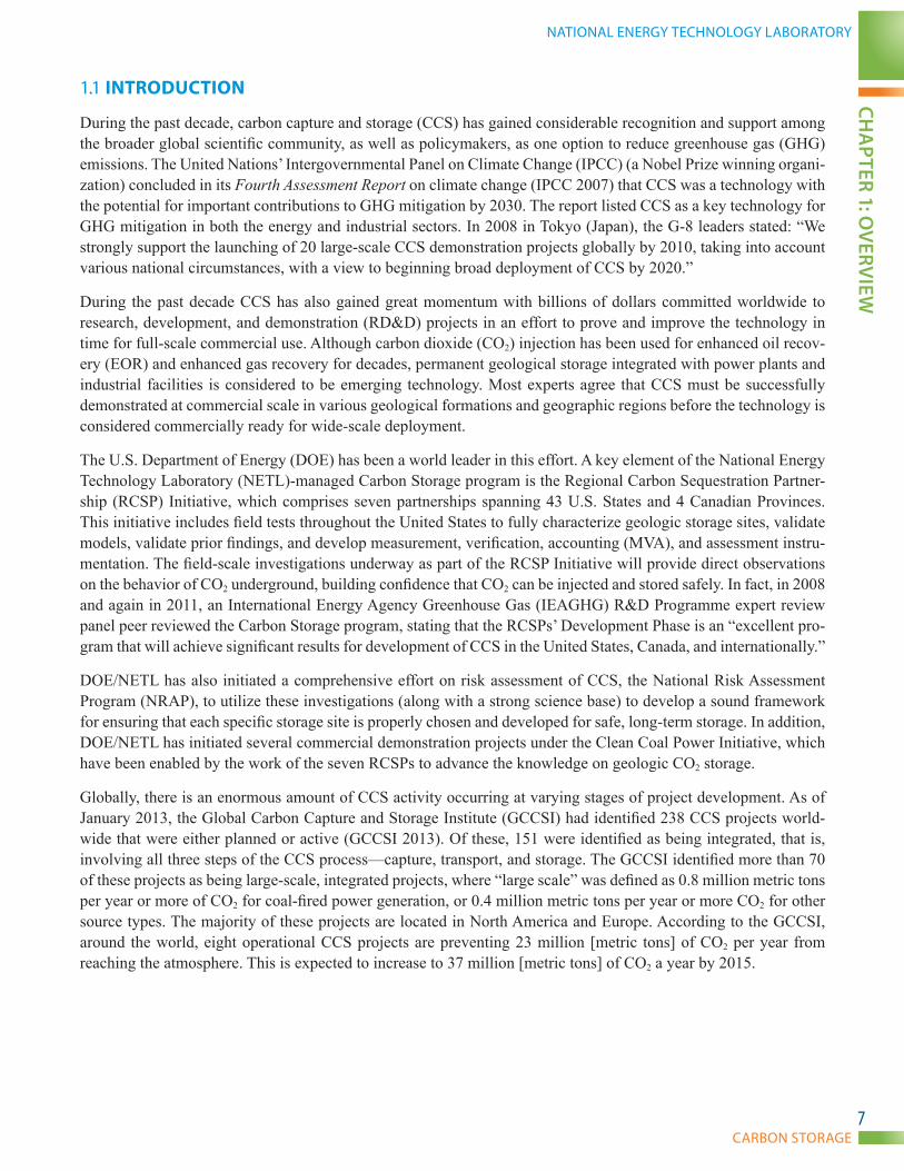
The CCS and Power Systems program area conducts and supports long-term, high-risk R&D to significantly re-duce fossil fuel power plant and other industrial emissions (including CO2) and substantially improve efficiency, leading to viable, near-zero-emissions fossil fuel energy systems. The success of DOE/NETL research and related program activities will enable CCS technologies to overcome economic, social, and technical challenges including cost-effective CO2 capture, compression, transport, and storage through successful CCS integration with power-generation systems; effective CO2 monitoring and verification; permanence of underground CO2 storage; and public acceptance. The overall program consists of four subprograms: Advanced Energy Systems, Carbon Capture, Carbon Storage, and Crosscutting Research (Figure 1-1). These four subprograms are further divided into numerous Tech-nology Areas. In several instances, the individual Technology Areas are further subdivided into key technologies. More detailed information on the Advanced Energy Systems, Carbon Capture, and Crosscutting Research subpro-grams can be found on the NETL website.
1 Referred to as Carbon Storage subprogram when discussed in terms of the CCS and Power Systems program area.
CARBON STORAGE
NATIONAL ENERGY TECHNOLOGY LABORATORYCH
APTER 1: O
VERV
IEw
9
CROSSCUTTINGRESEARCH
ADVANCED ENERGYSYSTEMSGasi�cation SystemsAdvanced Combustion SystemsAdvanced TurbinesSolid Oxide Fuel Cells
Plant OptimizationCoal Utilization SciencesUniversity Training and Research
CARBON CAPTUREPre-Combustion CapturePost-Combustion Capture
CARBON STORAGEInfrastructure (Regional Carbon Sequestration Partnerships)Geologic Storage Technologies and Simulation and Risk AssessmentMonitoring, Veri�cation, Accounting (MVA), and AssessmentCarbon Use and ReuseFocus Area for Carbon Sequestration Science
Reduced Cost of Electricity
Safe Storage and Use of CO2
Reduced Cost of Capturing CO2
Fundamental Research to Support Entire Program
Figure 1-1. CCS and Power Systems Subprograms
The Carbon Storage subprogram advances the development and validation of technologies that enable safe, cost-effective, permanent geologic storage of CO2. The technologies developed and small- and large-scale injection projects conducted through this subprogram will be used to benefit the existing and future fleet of fossil fuel power-generating facilities by developing tools to increase our understanding of geologic reservoirs appropriate for CO2 storage and the behavior of CO2 in the subsurface.
The Carbon Storage program is developing enabling technologies for both “first mover” and “broad deployment” types of projects to ensure permanent, safe, accountable, and efficient storage of CO2 while meeting regulatory requirements.
U.S. DEPARTMENT OF ENERGY
TECHNOLOGY PROGRAM PLAN
CHA
PTER
1: O
VER
VIE
w
10
“First mover projects” include early, commercial-scale projects deployed with economic incentives that could offset capture costs in depleted oil reservoirs and saline formations. Large-scale testing of new technologies for first mover projects will be underway by 2020, with widespread commercialization by 2025. Projects in both storage types will target regionally significant formations in various depositional environments. First mover projects are expected to utilize sites that are easy to develop and expected to minimize business and technical risk. All other things being equal, it is anticipated that sites of minimum geologic complexity will be a priority.
“Broad deployment projects” are the next-generation, commercial-scale projects for CO2 storage in all storage types. Large-scale testing of new technologies for broad deployment projects will be underway by 2030, with wide-spread commercialization by 2035. Some of these advancements will be achieved through major improvements in existing technologies, while others represent development of novel methods and approaches. Broad deployment projects have an emphasis on saline formations, due to their storage resource potential. Geologic storage in all storage types will be necessary in order to store the large volumes needed to substantially reduce CO2 emissions throughout the United States. Due to the natural heterogeneity and variability of geologic formations—as well as variability of other factors such as surface conditions, land use, population density, etc.—broad deployment projects will potentially be more challenging than first mover projects.
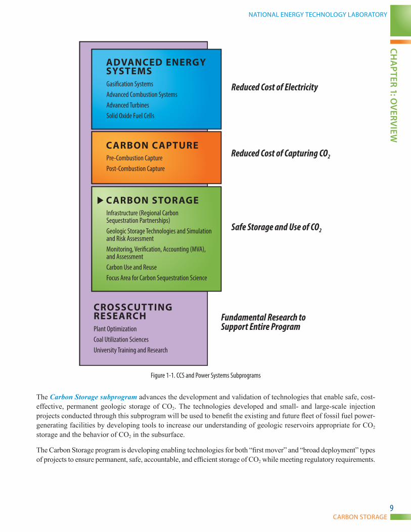
The Carbon Storage program is developing enabling technologies that can support the deployment of advanced power generation and capture technologies, but the technologies for storage are different from those being devel-oped for power plant and capture systems. Other CCS programs examine technologies in terms of 1st-Generation, 2nd-Generation, and Transformational technologies. First mover projects in the Carbon Storage program correspond to 2nd-Generation technologies in other CCS programs. Broad deployment projects in the Carbon Storage program correspond to Transformational technologies in other CCS programs. A comparison of technology category defini-tions used in the Carbon Storage program and other CCS programs is provided in Figure 1-2.
CARBON STORAGE PROGRAM
First Mover Projects—first mover projects can provide permanent, safe, accountable, and efficient storage of CO2 by 2025, while meeting regulatory requirements. First mover projects include early commercial-scale projects deployed with economic incentives that could offset capture costs in depleted oil reservoirs and saline formations.
Broad Deployment Projects—broad deployment projects are the next generation of commercial-scale projects that the Carbon Storage program is developing for advanced, cost-effective technologies by 2035. Broad deployment projects include challenging storage projects in all storage types with an emphasis on saline formations, due to their storage resource potential.
OTHER CCS PROGRAMS
1st-Generation Technologies—include technology components that are being demonstrated or that are commercially available.
2nd-Generation Technologies—include technology components currently in R&D that will be ready for demonstration in the 2020–2025 timeframe.
Transformational Technologies—include technology components that are in the early stage of development or are conceptual that offer the potential for improvements in cost and performance beyond those expected from 2nd-Generation technologies. The development and scaleup of these “Transformational” technologies are expected to occur in the 2016–2030 timeframe, and demonstration projects are expected to be initiated in the 2030–2035 time period.
Figure 1-2. CCS Technology Category Definitions

CARBON STORAGE
NATIONAL ENERGY TECHNOLOGY LABORATORYCH
APTER 1: O
VERV
IEw
11
1.3 CARBON STORAGE PROGRAM
1.3.1 BACKGROUND
Significant advances have been made in the development of CCS technologies since DOE launched the Carbon Storage program in 1997. Managed within DOE’s FE organization and implemented by NETL, the Carbon Storage program works to develop effective and economically viable technology options for CCS. To accomplish this, the Carbon Storage program focuses on developing technologies to store CO2 to reduce GHG emissions from energy producers and other industries without adversely affecting the supply of energy or hindering economic growth.
In order to obtain input from the CCS stakeholder community, a stakeholder workshop titled, Storage in Saline Formations R&D Workshop, was held in October 2011 to seek input from stakeholders on CCS research priorities. The purpose of this workshop was to assess state-of-the-art technologies, identify research needs, and highlight new approaches to advance the broad, commercial application of carbon storage. This workshop focused on the technical aspects of DOE’s Carbon Storage program, while recognizing that technical issues must be addressed within the context of an integrated system of capture, transport, and storage contained by a new regulatory framework.
A broad spectrum of approximately 50 researchers from industry, Government, national laboratories, academia, and other research institutions contributed to the success of this workshop. The participants summarized and assessed the current status of storage technology in the context of new U.S. Environmental Protection Agency (EPA) and State regulatory requirements for CO2 injection and GHG reporting described previously. Results from this work-shop were considered when revising this plan.
The Carbon Storage program will continue to develop and advance CCS technologies that will be ready for wide-spread, commercial deployment. Reaching these goals will require close collaboration with several other applied R&D programs within FE that are developing and demonstrating technologies integral to fossil-fueled power gen-eration with carbon capture.
1.3.1.1 PROGRAM STRUCTURE AND BUDGET
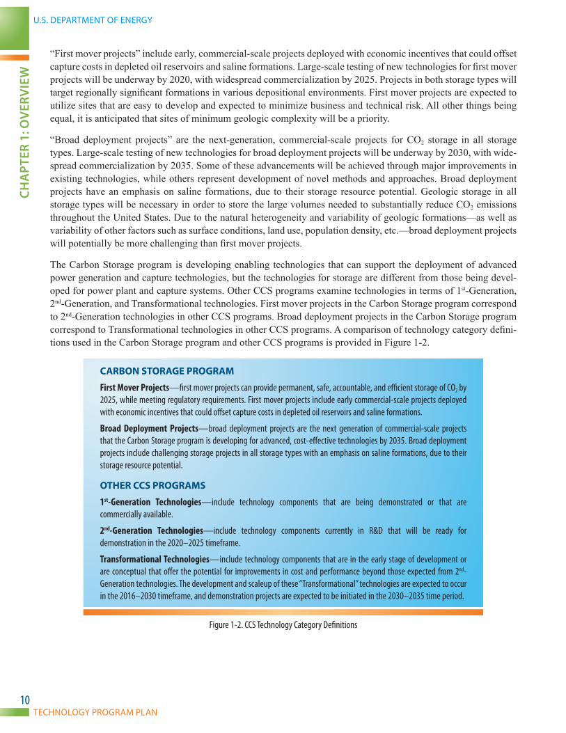
The Technology Areas that comprise DOE’s Carbon Storage program are shown in Figure 1-3. Three Technology Areas are combined together to form the Core R&D research component, which is driven by the technology needs determined by industry and other stakeholders, such as regulators. The Infrastructure Technology Area includes the RCSPs and other small- and large-volume field projects. This Technology Area is where validation of various CCS technology options and their efficacy are being confirmed and represent the development of the infrastructure necessary for the deployment of CCS. The Infrastructure Technology Area tests new technologies and benefits from specific solutions developed in the Core R&D component. In turn, data gaps and lessons learned from small- and large-scale field projects are fed back to the Core R&D component to guide future R&D.
U.S. DEPARTMENT OF ENERGY
TECHNOLOGY PROGRAM PLAN
CHA
PTER
1: O
VER
VIE
w
12
CARBON STORAGE PROGRAM
TECHNOLOGY AREASCore R&D Research (TRL 2–5) Development (TRL 5–7)
SUPPORTING ACTIVITY
GEOLOGIC STORAGE TECHNOLOGIES AND SIMULATION AND RISK ASSESSMENT
MONITORING, VERIFICATION, ACCOUNTING (MVA), AND ASSESSMENT
CARBON USE AND REUSE
INFRASTRUCTURE (REGIONAL CARBON SEQUESTRATION PARTNERSHIPS)
Focus Area for Carbon Sequestration Science(National Laboratory Support)
Figure 1-3. Carbon Storage Program Structure
These four main Technology Areas sponsor applied research at laboratory scale; validate promising technologies at pilot scale; and support large-scale, large-volume injection field projects at pre-commercial scale to confirm system performance and economics. The supporting activity is shown in Figure 1-3. The Focus Area for Carbon Sequestration Science is a strategic effort (identified in the CCRP work breakdown structure) to engage national laboratories, such as NETL’s Office of Research and Development, to work with the Carbon Storage program ex-tramural research teams. NETL’s Office of Research and Development organization is primarily responsible for this effort. This coordination provides DOE research and program managers the ability to look across similar activities, quickly fill critical gaps in research, and archive results in a corporate database, all of which will promote efficient knowledge for future researchers. More details about the key technologies and research focus for each Technology Area are discussed in subsequent sections.
The United States views international engagement as a means to complement the program’s approach to responding to reducing CO2 emissions. Accordingly, DOE is partnering with several international organizations, such as the IEAGHG R&D Programme, the Carbon Sequestration Leadership Forum (CSLF), and the North American Carbon Atlas Partnership (NACAP). DOE is also directly engaged in a number of large-scale CCS demonstration projects around the world, spanning five continents.
The Carbon Storage program also supports the development of best practices for CCS that will benefit projects implementing CCS at a commercial scale, such as in the Clean Coal Power Initiative and Industrial Carbon Capture and Storage programs. In general, DOE-applied research is being leveraged with small- and large-scale field proj-ects to assess the technical and economic viability of CCS as a GHG mitigation option. DOE has established the following plan to ensure that the goal of developing these technologies is met:
• Manage Core R&D activities within specific Technology Areas where separate research pathways develop the essential technologies needed to support storage operations.

CARBON STORAGE
NATIONAL ENERGY TECHNOLOGY LABORATORYCH
APTER 1: O
VERV
IEw
13
• Develop future infrastructure through the RCSP Initiative, as well as validate and field-test tech-nologies through all stages of onshore and offshore geologic storage, leading to commercialization.
• Engage a wide variety of industry—Federal, State, and local Government agencies; academia; and environmental organizations. This includes DOE’s Office of Science, which is working to develop the fundamental understanding of geological processes relevant to long-term CO2 storage.
• Work with NETL’s Office of Program Performance and Benefits (OPPB) to determine the benefits of research and establish a systems approach to confirm that technologies are capable of meeting Carbon Storage program goals.
DOE’s Carbon Storage program budget has increased over the last decade in response to U.S. efforts to reduce an-thropogenic CO2 emissions. The annual program budget has increased from approximately $10 million in 2000 to $115 million in 2012. The increase in the program budget reflects the high capital expenditures associated with the Validation and Development Phase field projects of the RCSP Initiative and other small-scale field projects.
The RCSP Initiative accounts for more than half of the program funding, with the remaining allotted to R&D that is conducted in collaboration with industry, States, private research institutions, and academia.
1.3.2 RECENT R&D ACTIVITIES
The RCSPs serve as the primary vehicle for promoting the development and deployment of CCS technologies developed within the Core R&D component. The Carbon Storage program is making meaningful progress that has resulted in a series of best management practices guidelines that will be helpful in the development of commercial-scale CCS projects. In particular, the commencement of the RCSP Initiative’s Development Phase brings within reach the realization of the most promising carbon mitigation solutions. These large-scale projects are possible due to the leadership and vision of both private and public sector partners, which has led to successful outcomes of numerous Core R&D projects and the first two phases of the RCSP Initiative. The goal of the Development Phase is to demonstrate and validate technologies associated with large-volume CO2 injection. These demonstrations are exhibiting how the deployment and eventual commercialization of such technologies can play a major role in a ro-bust CO2 mitigation strategy. The successful commercialization of CCS technologies will not only allow the United States and the world to continue to use fossil fuels in an environmentally responsible manner but, when coupled with the enhanced recovery of resources, these technologies will also provide an opportunity for greater recovery of domestic oil, natural gas, and coalbed methane (CBM).
The Carbon Storage program has achieved numerous accomplishments through the growth, expansion, and introduc-tion of new concepts and opportunities as a result of an adapting effort that incorporates novel activities to resolve issues uncovered by R&D activities and social demands. More details on programmatic accomplishments can be found in the DOE/NETL publication titled, Carbon Storage Program 2010–2011 Accomplishments, published in August 2012.

U.S. DEPARTMENT OF ENERGY
TECHNOLOGY PROGRAM PLAN
CHA
PTER
1: O
VER
VIE
w
14
1.4 RD&D STAGES, TECHNOLOGY READINESS LEVELS, AND PROJECT COST ESTIMATION
The RD&D of advanced fossil fuel power-generation technologies follows a sequential progression of steps toward making the technology available for commercial deployment.
1.4.1 RD&D STAGES
Figure 1-4 describes three of the RD&D stages contained in the CCRP. As the test scale increases, the duration and cost of the projects increase; however, the probability of technical success also tends to increase. Given the high technical risk at smaller scales, there will often be several similar projects that are simultaneously supported by the program. On the other hand, due to cost considerations, the largest projects are typically limited to one or two that are best-in-class. While the figure is not fully inclusive of all potential stages of RD&D (e.g., early analytic study and pre-commercial prototype are both excluded), it provides an accurate overview of the scope of each stage in terms of test length, cost, risk, and test conditions.
Short duration tests (hours/days)
Low to moderate cost
Medium to high risk of failure
Arti�cial and simulated operating conditions
Proof-of-concept and parametric testing
TRL 7–9 Demonstration(Large-Scale Testing)
TRL 5–6 Development(Pilot-Scale Field Testing)
Longer duration (weeks/months)
Higher cost
Low to medium risk of failure
Controlled operating conditions
Evaluation of performance and cost of technology in parametric teststo set up demonstration projects
Extended duration (typically years)
Major cost
Minimal risk of failure
Variable operating conditions
Demonstration at full-scale commercial application
TRL 2–4 Applied Research(Lab/Bench-Scale Testing)
RESEARCH, DEVELOPMENT, AND DEMONSTRATION
Progress Over Time
Figure 1-4. Summary of Characteristics at Different Development Scales
1.4.2 TECHNOLOGY READINESS LEVELS
The Technology Readiness Level (TRL) concept was adopted by the National Aeronautics and Space Administra-tion (NASA) to help guide the RD&D process. TRLs provide an assessment of the technology development progress on the path to meet final performance specifications. The typical technology development process spans multiple years and incrementally increases scale and system integration until final-scale testing is successfully completed. The TRL methodology is defined as a “systematic metric/measurement system that supports assessments of the ma-turity of a particular technology and the consistent comparison of maturity between different types of technology.”2
The TRL for a technology is established based upon the scale, degree of system integration, and test environment in which the technology has been successfully demonstrated. Figure 1-5 provides a schematic outlining the relation-ship of those characteristics to the nine TRLs.
2 Mankins, J., Technology Readiness Level White Paper, 1995, rev. 2004, Accessed September 2010. http://www.artemisinnovation.com/images/TRL_White_Paper_2004-Edited.pdf

CARBON STORAGE
NATIONAL ENERGY TECHNOLOGY LABORATORYCH
APTER 1: O
VERV
IEw
15
TRL 8TRL 3TRL 2TRL 1 TRL 7TRL 6TRL 5TRL 4 TRL 9
RESEARCH, DEVELOPMENT, AND DEMONSTRATION
TECHNOLOGY DEVELOPMENT
Concepts Lab/Bench Scale Pilot Scale Full ScalePre-Commercial
COM
MERCIA
L DEPLO
YMEN
TDEMONSTRATION
Paper Study Component Level Prototype System Full Plant
Simulated Actual Operational
TECH
NOLO
GYSC
ALE
SYST
EMIN
TEGR
ATIO
NTE
STEN
VIRO
NMEN
T
Figure 1-5. Technology Readiness Level—Relationship to Scale, Degree of Integration, and Test Environment
The scale of a technology is the size of the system relative to the final scale of the application, which in this case is a full-scale commercial power production or industrial facility. As RD&D progresses, the scale of the tests in-creases incrementally from lab/bench scale, to pilot scale, to pre-commercial scale, and to full-commercial scale. The degree of system integration considers the scope of the technology under development within a particular re-search effort. Early research is performed on components of the final system, a prototype system integrates multiple components for testing, and a demonstration test of the technology is fully integrated into a plant environment. The test environment considers the nature of the inputs and outputs to any component or system under development. At small scales in a laboratory setting it is necessary to be able to replicate a relevant test environment by using simulated conditions—such as simulated cores and brines. As RD&D progresses in scale and system integration, it is necessary to move from simulated inputs and outputs to the actual environment (e.g., actual cores, small- or large-scale field tests, etc.) to validate the technology. At full-scale and full storage site integration, the test environment must also include the full range of operational conditions (e.g., startup and turndown).

U.S. DEPARTMENT OF ENERGY
TECHNOLOGY PROGRAM PLAN
CHA
PTER
1: O
VER
VIE
w
16
Figure 1-6 provides a schematic of the meaning of the TRLs in the context of the Carbon Storage program projects.
FOSSIL ENERGY CLEAN COAL RESEARCH PROGRAM
TRL 1
Readying Advanced Technology for Commercial Deployment
TRL 5-6TRL 2-4 TRL 7-9
Basic ResearchO�ce of Science
Process and EngineeringDevelopment
Applied ResearchBridges basic research and
technology development programs
Large-ScaleTesting and Evaluation
Demonstrations*
TechnologyDevelopment
Crosscutting Research
DOE O�ce of Science Research
Technology Advances Toward Deployment Readiness
University and Industry Research
Feedback
Feedback
*The demonstration platforms typically consist of multiple technologies, some of which are developed under the CCUS and Power Systems R&D program area, while others may have been developed by the recipients or their equipment suppliers. Accordingly, some of the technologies that comprise the entire demonstration platform may enter with a TRL 9 rating and are considered to be “enabling” technologies necessary to facilitate the demonstration of the less mature technologies.
Figure 1-6. Schematic of the TRL Concept

CARBON STORAGE
NATIONAL ENERGY TECHNOLOGY LABORATORYCH
APTER 1: O
VERV
IEw
17
1.4.3 RD&D PROJECT COST ESTIMATION
Each of the RD&D stages previously described in Figure 1-5 correlates to a TRL. Figure 1-7 is an example of the progression of TRL and costs as a technology moves from the concept stage through commercial demonstration. The costs shown are based on past technology development efforts conducted at similar scales.
The cost of early research for a technology project is relatively low, but rises with increases in scale and greater system integration, and then transitions from simulated to actual to operational testing environments. The Carbon Storage program supports projects with TRLs from 3 to 8. Out of 78 projects evaluated in 2012, the distribution of these projects and their associated TRL scores are as follows: 39 percent with completed project TRL values of 3–4, 44 percent completed project TRL values of 5–6, and 17 percent completed project TRL values of 7–8.
Analytic StudyTRL 1-2(1–2 years)≤$1M
Laboratory/Bench-ScaleTRL 3-4<1 MW(2–4 years)$500K–10M
Pilot-ScaleTRL 5-61–20 MW(4–6 years)$5–75M
Pre-CommercialDemonstrationTRL 750–200 MW(5–10 years)$50–150M
Commercial-ScaleDemonstrationTRL 8-9>200 MW(7–10 years)≥$100M
Available forDeployment
Figure 1-7. Representative Timing and Cost for Technology Component Development

U.S. DEPARTMENT OF ENERGY
TECHNOLOGY PROGRAM PLAN
CHA
PTER
2: G
OA
LS A
ND
BEN
EfIT
S
18
CHAPTER 2: GOALS AND BENEFITS

CARBON STORAGE
NATIONAL ENERGY TECHNOLOGY LABORATORYCH
APTER 2: G
OA
LS AN
D BEN
EfITS
19
2.1 GOALS
The goals of the Carbon Storage program support the energy goals established by the Administration, DOE, FE, and the CCRP.
2.1.1 CCRP GOALS
Currently, the CCRP is pursuing the demonstration of 1st-Generation carbon capture technologies with existing and new power plants and industrial facilities using a range of capture alternatives and CO2 storage projects in a variety of geologic formations. In parallel, to drive down the costs of implementing CCS, the CCRP is pursuing RD&D to decrease the cost of electricity (COE) and capture costs and increase base power-plant efficiency, thereby reducing the amount of CO2 that has to be captured and stored per unit of electricity generated. FE/NETL is developing a portfolio of technology options to enable this country to continue to benefit from using our secure and affordable coal resources. The challenge is to help position the economy to remain competitive, while concurrently reducing carbon emissions.
There are a number of technical and economic challenges that must be overcome before cost-effective CCS tech-nologies can be implemented. The experience gained from the sponsored demonstration projects focused on state-of-the-art (1st Generation) CCS systems and technologies will be a critical step toward advancing the technical, economic, and environmental performance of 2nd-Generation and Transformational systems and technologies for future deployment. In addition, the core RD&D projects being pursued by the CCRP leverage public and private partnerships to support the goal of broad, cost-effective CCS deployment.
The path ahead with respect to advancing CCS technologies, particularly at scale, is challenging. First mover projects will focus on well characterized depleted oil reservoirs and regionally significant saline formations where minimal injection issues are anticipated and enabling technologies will be available to ensure permanent, safe, accountable, and efficient storage of CO2 while meeting regulatory requirements. By 2030, as broad deployment of carbon storage occurs, more complex formations will need to be targeted for storage applications and more advanced technologies will be required. Management of formation liquids will be more challenging for broad de-ployment projects when compared to first mover projects. Tracking CO2 plume migration and risk assessment will require better tools for more complex formations.
2.1.2 CARBON STORAGE PROGRAM GOALS
The Carbon Storage program has the following goals:
• Develop and validate technologies to ensure for 99 percent storage permanence.
• Develop technologies to improve reservoir storage efficiency while ensuring containment effectiveness.
• Support industry’s ability to predict CO2 storage capacity in geologic formations to within ±30 percent.
• Develop Best Practice Manuals (BPMs) for monitoring, verification, accounting (MVA), and as-sessment; site screening, selection, and initial characterization; public outreach; well management activities; and risk analysis and simulation.
Consistent with these overall goals, the Carbon Storage program has established these goals for 2020 and 2030:
2020—For first mover projects, develop and validate technologies to ensure 99 percent storage permanence while offsetting capture cost with utilization. For these projects, it is assumed that saline storage must comply with the EPA Class VI regulations described previously. Large-scale testing of these technologies will be underway by 2020 and widespread commercialization will be underway by 2025.
2030—For broad deployment projects, develop and validate technologies to improve storage ef-ficiency, and ensure 99 percent storage permanence while ensuring containment effectiveness in all
U.S. DEPARTMENT OF ENERGY
TECHNOLOGY PROGRAM PLAN
CHA
PTER
2: G
OA
LS A
ND
BEN
EfIT
S
20
storage types. Large-scale testing of these technologies will be underway by 2030 and widespread commercial application will be underway by 2035.
2.2 CARBON STORAGE PROGRAM BENEFITS
NETL’s OPPB conducts analyses to demonstrate how R&D activities support national and international priorities related to energy supply, energy use, and environmental protection. OPPB examines the following three areas of analysis (with respect to the Carbon Storage program):
• Systems—Places research objectives (e.g., improvements in the cost and efficiency of CCS tech-nologies) in the context of its impacts on commercial power-generation systems and other indus-trial processes.
• Policy—Places CCS in the context of regulatory compliance and environmental policy.
• Benefits—Combines technology and policy to show economic and environmental costs and ben-efits that a successful Carbon Storage program will provide both domestically and internationally.
2.2.1 ECONOMIC, TECHNICAL, AND ENVIRONMENTAL BENEFITS
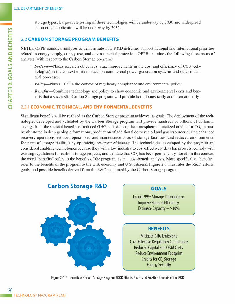
Significant benefits will be realized as the Carbon Storage program achieves its goals. The deployment of the tech-nologies developed and validated by the Carbon Storage program will provide hundreds of billions of dollars in savings from the societal benefits of reduced GHG emissions to the atmosphere, monetized credits for CO2 perma-nently stored in deep geologic formations, production of additional domestic oil and gas resources during enhanced recovery operations, reduced operational and maintenance costs of storage facilities, and reduced environmental footprint of storage facilities by optimizing reservoir efficiency. The technologies developed by the program are considered enabling technologies because they will allow industry to cost-effectively develop projects, comply with existing regulations for carbon storage projects, and validate that CO2 has been permanently stored. In this context, the word “benefits” refers to the benefits of the program, as in a cost-benefit analysis. More specifically, “benefits” refer to the benefits of the program to the U.S. economy and U.S. citizens. Figure 2-1 illustrates the R&D efforts, goals, and possible benefits derived from the R&D supported by the Carbon Storage program.
Carbon Storage R&D
Core R&D
Regional CarbonSequestrationPartnerships
Focus Areafor CS
ScienceBENEFITS
GOALS
Ensure 99% Storage Permanence Improve Storage E�ciency Estimate Capacity +/-30%
Mitigate GHG EmissionsCost-E�ective Regulatory Compliance
Reduced Capital and O&M Costs Reduce Environment Footprint
Credits for CO2 StorageEnergy Security
Figure 2-1. Schematic of Carbon Storage Program RD&D Efforts, Goals, and Possible Benefits of the R&D
CARBON STORAGE
NATIONAL ENERGY TECHNOLOGY LABORATORYCH
APTER 2: G
OA
LS AN
D BEN
EfITS
21
Many of the technologies being developed by the Carbon Storage program to address various facets of carbon stor-age have the potential to perform at lower cost than currently available technologies (i.e., technologies that would be deployed in storage operations if such were to be undertaken now or in the near future). The cost-reducing potential of technologies being developed by the Carbon Storage program could be significant.
The cost reductions enabled by the Carbon Storage program could make mitigation of CO2 emissions from the power and other industrial sectors more cost-effective relative to other alternatives. This serves to keep the COE low and provides an economic benefit in terms of maintaining income levels for energy consumers; increasing di-rect, indirect, and induced employment from the CCS infrastructure build out; positively impacting gross domestic product; and avoiding social costs through the successful mitigation of CO2 emissions.
The Carbon Storage program is developing four primary mathematical models to evaluate the program’s benefits. Two of the models are spreadsheet models; the CO2 Saline Storage Cost Model is a model of a saline storage site, while the CO2-EOR Storage Cost Model is a model of a CO2-EOR reservoir. Both models estimate costs and rev-enues from the perspective of an owner or operator of a saline storage site or CO2-EOR site and can be applied over a variety of potential saline storage formations or oil reservoirs. The third model, the CO2 Capture, Transport, Utilization, and Storage (CTUS) Model, is a higher level model that examines potential sources of CO2 emissions and possible storage sites for CO2 across the United States. The fourth model, the CO2 CTUS-NEMS Model, is the Energy Information Agency’s National Energy Modeling System (NEMS), a macroeconomic model of the U.S. economy that emphasizes the energy sector of the economy, with a version of the CO2 CTUS Model within it.

U.S. DEPARTMENT OF ENERGY
TECHNOLOGY PROGRAM PLAN
CHA
PTER
3: T
ECH
NIC
AL
PLA
N
22
CHAPTER 3: TECHNICAL PLAN
CARBON STORAGE
NATIONAL ENERGY TECHNOLOGY LABORATORYCH
APTER 3: TECH
NIC
AL PLA
N
23
As illustrated in Figure 1-3, there are four Technology Areas in the Carbon Storage program. The first three, collective-ly represent the Core R&D effort, which focuses on developing new CCS technologies to the point of pre-commercial demonstration. These areas are Geologic Storage Technologies and Simulation and Risk Assessment (GSRA); Moni-toring, Verification, Accounting (MVA), and Assessment; and Carbon Use and Reuse. The fourth Technology Area, Infrastructure (RCSPs), represents the development of the infrastructure necessary for CCS deployment.
Within each Technology Area, specific challenges or uncertainties have been identified and research pathways have been constructed to address these challenges. The level of technology R&D conducted in the Core R&D efforts ranges from laboratory- to pilot-scale activities, typically having TRLs in the range of 2–5 for the technologies necessary for demonstration by 2020 to support first mover projects and demonstration by 2030 to support broad deployment projects. Technologies supporting first mover projects may currently be at the laboratory scale or pilot-scale testing and should be available for large-scale testing by 2020. Technologies supporting broad deployment projects are new, novel tools and approaches that can radically reduce costs, enable storage in all formation types, and will most likely not be available for demonstration until 2030. For the most part, existing technologies are cur-rently available technologies that need to be adapted for deployment in commercial geologic storage applications and are incorporated in field projects carried out by the program for purposes of validation of system performance.
Technologies are normally developed in the Core R&D projects to the point where individual companies, utilities, and other business entities are able to design, manufacture, and build the equipment and instrumentation needed to implement or commercialize the processes. The Core R&D efforts are implemented through cost-shared coopera-tive agreements and grants with industry and academic institutions, field work research at other national laborato-ries, and research at NETL’s Office of Research and Development.
3.1 GEOLOGIC STORAGE TECHNOLOGIES AND SIMULATION AND RISK ASSESSMENT (CORE R&D)
3.1.1 BACKGROUND/TECHNICAL DISCUSSION
Geologic CO2 storage involves the injection of supercritical CO2 into deep geologic formations into injection zones, which are overlain by confining zones or impermeable seals that prevent CO2 from migrating to the surface. Cur-rent research and field studies are focused on developing a better understanding of the science and technologies for onshore and offshore storage reservoirs, which include: clastic formations, carbonate formations, unmineable coal seams, organic-rich shales, and basalt interflow zones.
Natural storage of oil, natural gas, and CO2 in deep geologic reservoirs has occurred for millions of years. Carbon dioxide is a constituent of natural gas deposits and can be trapped in nearly pure deposits. Over the past 40 years, the petroleum industry has injected predominately natural CO2 into depleted oil reservoirs for the recovery of ad-ditional oil through EOR processes. Lessons learned from natural systems, EOR operations, natural gas storage, and sponsored CO2 storage projects are all important for developing storage technologies for a future CCS industry.
Computer simulators (models) are the tools used to predict the movement and behavior of CO2 once it is injected into the subsurface. Models serve as critical tools in a framework to identify, estimate, and mitigate risks arising from CO2 injection into the subsurface. The models are used to facilitate more effective site characterization, design injection operations, optimize monitoring design, and predict the eventual stabilization and long-term fate of the injected CO2. Computer simulators can also be used to predict geochemical and thermal changes that may occur in the reservoir; geomechanical effects on the target formation, confining zones, and potential release pathways, such as faults, fractures, and wellbores; and the effect of biological responses in the presence of supercritical CO2.
Risk assessment (or more formally, risk analysis, which tailors the development of effective risk assessment proto-cols and models to individual CO2 storage sites) is performed at the early stages of a project to help with site selec-tion, communicate project goals and procedures to the public, and aid regulators in permitting for the project. Risk assessment is essential to identifying potential site problems and developing mitigation procedures so that immedi-
U.S. DEPARTMENT OF ENERGY
TECHNOLOGY PROGRAM PLAN
CHA
PTER
3: T
ECH
NIC
AL
PLA
N
24
ate action can be implemented, should a problem arise. Risk assessment must examine not only technical risk, but also project implementation risks, operational risks, and long-term storage risks. Quantifying risks is necessary to support site selection and inform project developers as they design MVA protocols and well designs. These results are used to form assessments of long-term project costs, potential liabilities, and decisions on decommissioning and long-term stewardship.
As the simulation models are refined with new data, the uncertainty surrounding the identified risks decreases, which in turn provides a more accurate risk assessment and mitigation plan for each project site. Both qualitative and quantitative protocols will be developed to ensure the safe and permanent storage of CO2. Results from the simulation models are incorporated into risk assessments on a project-by-project basis and on a larger basin-scale. As CCS becomes deployed in major basins, macro model results will be needed to manage reservoirs for pressure management, plume migration, and potential risks of multiple CO2 injection projects across the basin.
Figure 3-1 illustrates the geologic storage concept and the different research efforts underway within the GSRA Technology Area.
Figure 3-1. Subsurface Processes, Tools, and Technologies Addressed in the GSRA Research Activities
3.1.2 GSRA R&D APPROACH
The Carbon Storage program supports research to develop technologies that can improve containment and injec-tion operations, increase reservoir storage efficiency, and mitigate potential release of CO2 in all types of storage formations. Research conducted in the near and long term will augment existing technologies to ensure permanent storage of CO2 for the emerging CO2 storage industry. The program supports research that will improve the nation’s scientific understanding in six key technologies: wellbore; mitigation; fluid flow, pressure, and water management; geomechanical impacts; geochemical impacts; and risk assessment.
Development of scientific understanding of fluid flow, geomechanical, and geochemical processes relies upon com-puter simulators, in combination with laboratory and field validation. A significant amount of work has been com-pleted by industry and academia to develop 1st-Generation computer simulators for CO2 that incorporate thermal,

CARBON STORAGE
NATIONAL ENERGY TECHNOLOGY LABORATORYCH
APTER 3: TECH
NIC
AL PLA
N
25
hydrologic, mechanical, chemical, and biological processes related to CO2 injection. Some simulators only incor-porate one or two of these processes, while others incorporate coupling among multiple processes. Several different 1st-Generation simulators (both coupled and uncoupled) are currently being validated in field projects. Simulations are utilized to predict the following:
• Temporal and spatial migration of the CO2 plume and pressure front
• Effects of geochemical reactions on CO2 trapping and long-term porosity and permeability
• Seal and wellbore integrity; the impact of thermal/compositional gradients in the reservoir
• Potential pathways for CO2 leakage
• Importance of redundant seals for integrity in confining zone
• Potential effects of unplanned hydraulic fracturing
• Extent of upward migration of CO2 along the outside of the well casing
• Impacts of cement dissolution
• Consequences of wellbore failure
Simulation is a critical step in the systematic development of a monitoring program for a geologic CO2 storage project, because the selection of an appropriate measurement method and/or instrument is based on whether the method or instrument can provide the data necessary to address a particular technical question. Effective monitor-ing can validate that the project is performing as expected from predictive models. This is particularly valuable in the early stages of a project when the opportunity exists for project modifications to ensure long-term storage and improve efficiency. Monitoring data collected early in a project may be used to calibrate and refine the model, decreasing the uncertainties of predictions over the longer term performance of the project.
Risk assessment is used in many disciplines and, in recent years, tools and methods have been adapted for CO2 geologic storage. Extensive databases of features, events, and processes have been developed in order to facilitate identification of site- and project-specific risks. Various tools have been developed to qualitatively or quantitatively evaluate the likelihood and consequence of risk scenarios, and the probability that a particular event will occur.
More information on the Carbon Storage program’s simulation and risk assessment technologies is available in the BPM titled, Risk Analysis and Simulation for Geologic Storage of CO2.
3.1.3 KEY TECHNOLOGIES AND RESEARCH TIMELINE
The table below, Table 3-1, provides a brief description of the key technologies within the GSRA Technology Area.
Table 3-1. GSRA Key Technologies Research DescriptionKey Technology Description
Wellbore Improve wellbore construction materials and technologies to ensure safe and reliable injection operations and long-term containment of CO2 in subsurface reservoirs.
Mitigation Mitigation technologies developed that will help ensure that possible release of CO2 through natural or man-made pathways can be sealed effectively.
Fluid Flow, Pressure, and Water Management
Fluid flow, fluid pressure, and water management in the injection reservoir along with sealing capability of caprocks, are factors that must be understood in order to design injection operations, optimize injection rates, and make efficient use of reservoir storage space.
Geomechanical Impacts Understand the potential for geomechanical deformation to the injection zone, confining zone, and wellbore as a result of CO2 injection. Such impacts may include induced seismicity, faulting, fracturing, and damage to wellbore materials.
Geochemical Impacts Understand geochemical processes associated with CO2 injection, and how these chemical reactions may impact physical processes in the storage formation, the caprock, the wellbore, and along potential release pathways.
Risk Assessment Improve quantitative risk assessment strategies used in CO2 injection operations critical to the design, optimization, and implementation of an effective risk assessment plan.

U.S. DEPARTMENT OF ENERGY
TECHNOLOGY PROGRAM PLAN
CHA
PTER
3: T
ECH
NIC
AL
PLA
N
26
Each key technology for GSRA has specific research pathways, which are shown as arrows on the GSRA research timeline in Figure 3-2. For each research pathway, the timeline begins with applied research (TRL 2–4), continu-ing with system integration and small-scale testing (TRL 5–6), and finally culminating with large-scale testing (TRL 7–9). In general, new technologies for first mover projects are intended to be in the process of large-scale testing by 2020, with widespread commercialization underway by 2025. New technologies for broad deployment projects will have large-scale testing underway by 2030, and widespread commercial deployment by 2035.
GEOLOGIC STORAGE TECHNOLOGIES AND SIMULATION AND RISK ASSESSMENT RESEARCH TIMELINE
• To Be Filled• To Be Filled
KEY TECHNOLOGIES PROGRAM GOALS 2020 20302010 2040
Wellbore
Fluid Flow, Pressure, and Water Management
Mitigation
Risk Assessment
Adv. Tools to Ensure Wellbore Integrity – Complex Formations
Wellbore Integrity Technologies
Detection and Mitigation of Leakage
RA Tools for Early Storage Formation Targets
Geochemical Impacts
Geomechanical Impacts
Adv. Models to Reduce Cost, Uncertainty and Increase Accuracy
Incorporate Geochem. Impacts into Models
Adv. Models to Reduce Cost, Uncertainty and Increase Accuracy
Incorporate Geomech. impacts into Models
Models and Methodology to Manage Extracted Brine
Assess Basin-Scale Impacts with Reservoir Models
+ 99% storage permanence;
Predict storage capacity to +/- 30%;
Improve storage e�ciency
+99% storagepermanence
+99% storagepermanence
CO2-Resistant Construction Materials
Novel Well Completion Technology to Increase Injectivity
Better Tools to Identify Leakage
Adv. Models to Reduce Cost, Uncertainty, and Increase Accuracy
Improved, Quantitative RA Tools Integrated with Field Operations
Novel Methods for Permanent Low Cost Mitigation of Release Pathways
Applied Research (TRL 2–4)
Development (TRL 5–6)
Large-Scale Testing (TRL 7–9)
First M
over
Broad
Deployment
Figure 3-2. Research Timeline for GSRA
Research pathways for each of the key technologies—wellbore; mitigation; fluid flow, pressure, and water manage-ment; geomechanical impacts; geochemical impacts; and risk assessment—are summarized below.
► wELLBORE—Wellbore integrity is a key technology that addresses the need to assess and construct well-bores to ensure safe and reliable injection operations as well as long-term containment of CO2 in the tar-geted reservoir. Wellbore materials must be resistant to chemical corrosion from injected fluids, they must be sufficiently strong to withstand mechanical stresses associated with injection, and they must have good cement bonds to ensure containment. Specific research pathways for wellbore improvements are:
• 2020: Develop new wellbore integrity technologies for early storage formations and CO2 resistant con-struction materials. Research includes use of wellbore deformation measurements as a diagnostic tool; post-mortem studies of older wellbores; and testing of materials suitable for casing, linings, and cements.

CARBON STORAGE
NATIONAL ENERGY TECHNOLOGY LABORATORYCH
APTER 3: TECH
NIC
AL PLA
N
27
• 2030: Develop (1) advanced tools to ensure wellbore integrity in complex formations, such as sub-salt, low strength, and overpressured conditions as encountered in broad deployment projects; and (2) novel well completion techniques to increase reservoir injectivity without compromising containment.
► MITIGATION—Mitigation is a key technology that addresses the need to prevent and correct any potential release of CO2 from its intended geologic storage reservoir. Permanent CO2 storage relies on the presence of a confining zone that will trap the CO2 for millennia. Wellbores and natural geologic features, including faults and fractures, could become release pathways for CO2 to migrate to the surface or into underground formations. Research is needed to develop methods to detect potential release pathways and to seal these release pathways. Specific mitigation research pathways include:
• 2020: Develop improved systems for detection and remediation of CO2 leakage from wells and natu-ral pathways. Research includes use of geomechanical simulation to assess potential caprock leakage and remediation and development of chemical additives and biomineralization technologies that may act as effective sealants without impacting injectivity and capacity efficiency in the storage formation.
• 2030: Develop (1) lower cost tools with higher resolution, including advanced seismic and tracer technologies for leak identification in wells and from the natural system; and (2) novel methods, such as nanocomposites and other materials, for permanent mitigation of release pathways.
► fLUID fLOw, PRESSURE, AND wATER MANAGEMENT—Fluid flow, pressure, and water management is a key technology that provides the knowledge and tools needed to design effective injection operations, optimize injection rates, make efficient use of reservoir storage space, and ensure the sealing capability of caprock formations. The flow of CO2 in the reservoir and attendant changes in temperature and pressure are affected by many factors, such as sedimentary, structural, and hydrologic properties of the reservoir, and the presence of naturally occurring fractures. A number of two- and three-dimensional computer simulators exist today for predicting CO2 flow, temperature changes, and pressure changes based on intrinsic reservoir properties. However, improvements are needed to develop coupled, basin-scale simulators that model ef-fects of factors, such as fractures, and can be used for a variety of storage types. In addition, the displace-ment of water by CO2 must be understood and appropriate water management techniques employed. Spe-cific research pathways in fluid flow, pressure, and water management include:
• 2020: Reservoir modeling efforts that assess basin-scale modeling impacts of injection on fluid flow and fluid pressure conditions in the reservoir, as well as research designed to help improve injection operations, injectivity, and sweep efficiency in reservoir types targeted in first mover projects. The results will improve understanding of injection impacts on open and closed systems in a variety of depositional environments and will be used in assessing and mitigating risks at both project and basin scale.
• 2030: Develop (1) new, fit-for-purpose numerical fluid flow models that reduce cost and uncertain-ty of simulations while increasing their accuracy; and (2) models and methods to manage extracted water and brine. Research includes efforts to improve regional hydrologic modeling and efforts to link water management and management of pressure and plume migration.
► GEOMECHANICAL IMPACTS—Another key technology is geomechanical impacts. Geomechanical defor-mation triggered by increased fluid pressure during injection operations could potentially result in faulting, fracturing, microseismicity, damage to the wellbore, and other types of elastic and inelastic deformation. Ide-ally injection pressures should be kept low to prevent CO2 release associated with geomechanical impacts. To ensure that this condition is met, research is needed to understand the potential for geomechanical deforma-tion to the reservoir, seal, and wellbore as a result of CO2 injection. Research pathways in this area include:
• 2020: Integrate geomechanical impacts into models to assess and mitigate potential risk. Research includes studies of faults, fractures, seismicity, and wellbore damage from pressure changes related to injection and integration of results into basin-scale models.

U.S. DEPARTMENT OF ENERGY
TECHNOLOGY PROGRAM PLAN
CHA
PTER
3: T
ECH
NIC
AL
PLA
N
28
• 2030: Develop new, coupled geomechanical/fluid flow models that reduce costs and uncertainties in model predictions while increasing their accuracy. Use these models to assess and mitigate geo-mechanical impacts of injection in formations encountered in broad deployment projects.
► GEOCHEMICAL IMPACTS—Geochemical impacts research is needed to understand chemical processes re-lated to CO2 storage, including aqueous speciation, dissolution/precipitation, microbial-mediated redox reac-tions, ion-exchange between solutions and minerals, and surface chemical reactions occurring at phase inter-faces. All of these reactions will have impacts on the physical processes taking place in the storage formation, caprock, and along potential release pathways. Computer simulators are used to model these impacts, and improvements are needed to better constrain these models. Research pathways for this key technology are:
• 2020: Assess geochemical changes related to CO2 injection and integrate results into basin-scale models. Studies are investigating mineralization rates, CO2-water interactions, and changes in mi-crobial communities related to injection and integrating into basin-scale models.
• 2030: Develop advanced, coupled, geochemical and bio-geochemical/fluid flow models for optimiz-ing injection efficiency, reducing cost, and increasing certainty; and use these models to assess and mitigate geochemical impacts of injection in formations encountered in broad deployment projects.
► RISK ASSESSMENT—Risk assessment is a key technology that focuses on the systematic identification of risk factors in a CCS project. In addition to identifying potential risk factors, it is necessary to define or pre-dict specific consequences. Numerical simulation, based on field operations experience, is used to support the development of a rigorous risk assessment strategy that includes quantification of risk factors. Research pathways for risk assessment include:
• 2020: Develop qualitative risk assessment tools for formations targeted in first mover projects. Research includes efforts to develop standard processes for risk assessment and efforts to integrate risk assessment with reservoir simulation, operations design, and CO2 monitoring activities.
• 2030: Develop improved quantitative risk assessment tools and integrate risk assessment with field op-erations. Research includes post-audits of past projects for validating specific risk assessment approach-es and comparing predictions with observations to demonstrate reliability of methods and models.
3.2 MONITORING, VERIFICATION, ACCOUNTING (MVA), AND ASSESSMENT (CORE R&D)
3.2.1 BACKGROUND/TECHNICAL DISCUSSION
Monitoring, verification, accounting (MVA), and assessment efforts are designed to confirm permanent storage of CO2 in geologic formations, both onshore and offshore, through multilevel monitoring programs that are both reli-able and cost-effective. Monitoring is an important aspect of CO2 injection and storage because it focuses on a num-ber of permanence issues. Onshore monitoring technologies are developed for surface (atmospheric), near-surface (underground source of drinking water formations), and subsurface (injection and confining zones) applications to ensure that injection and abandoned wells are structurally sound and that CO2 will not endanger sources of drinking water. Since Federal and State GHG regulations or emission trading programs have been developed, monitoring has gained importance as a means to ensure CO2 has been safely and permanently stored underground. The location of the injected CO2 plume in the underground formation can also be determined, via monitoring, to satisfy operating requirements for onshore storage under EPA’s Underground Injection Control program and GHG reporting pro-grams, to ensure that potable groundwater and ecosystems are protected.
Differences in the offshore and onshore environments lead to differences in deployment of MVA technologies, which need to be further evaluated. For example, offshore seismic surveys are carried out using systems towed by ships. Geophysical measurements for monitoring the injection and confining zones may also be deployed on the seabed. Monitoring techniques are being developed to detect CO2 in the water column. Also, offshore infrastruc-

CARBON STORAGE
NATIONAL ENERGY TECHNOLOGY LABORATORYCH
APTER 3: TECH
NIC
AL PLA
N
29
ture, technology, and CO2 storage reservoirs can vary considerably, so MVA efforts should be designed to meet site-specific needs.
The initial deployment of CCS technologies with enhanced hydrocarbon recovery operations poses specific chal-lenges for the monitoring and accounting of CO2 stored in these formations. The mixing of fluids and gases with similar composition will require that novel approaches and tools be deployed to account for injected, stored, and produced fluids stored in the geologic formations.
MVA tools have advanced in application, sensitivity, and resolution over the last 10 years as both large- and small-scale demonstrations of geologic CO2 storage have taken place. Large commercial operations—such as Sleipner in Norway, Weyburn in Canada, In Salah in Algeria, and efforts of the RCSPs in the United States—have resulted in the application and validation of monitoring tools from DOE’s Carbon Storage R&D program that identify CO2 in the target formation, overburden, at the surface, and in potential release pathways from the formation to the surface. For example, the Carbon Storage program supported the first successful application of gravity measurements in a CCS project to augment seismic monitoring at the Sleipner project. In the In Salah project, the Carbon Storage program supported modeling and analysis of InSAR data, which was important to understanding pressure changes in and above the reservoir due to CO2 injection.
3.2.2 MVA R&D APPROACH
The primary benefit of MVA research is the development of tools and protocols that provide assurance of storage permanence for geologic CO2 storage. It is necessary to develop advanced monitoring technologies, as well as sup-porting protocols, in order to decrease the cost and uncertainty in measurements needed to satisfy regulations for tracking the fate of subsurface CO2 and quantifying any emissions to the atmosphere.
Figure 3-3 displays the various monitoring tools that may be employed to monitor the fate of the CO2 within a geo-logic storage system. This includes tools designed to measure CO2 and its effects in the subsurface, the near-surface region, and the atmosphere. Data analyzed through acquisition of information from these tools may also be used to optimize injection operations, sweep efficiency, and identify release pathways. MVA challenges and uncertainties are discussed in depth in the second version of NETL’s Best Practices for Monitoring, Verification and Accounting of CO2 Stored in Deep Geologic Formations—2012 Update (DOE/NETL-2012/1568).
The Carbon Storage program supports MVA research in four key technologies: atmospheric monitoring, near-surface monitoring, subsurface monitoring, and intelligent monitoring. Research in these areas, in conjunction with small- and large-scale injection projects, is expected to produce advanced MVA tools that can be applied in a systematic approach to address monitoring requirements across the range of storage formations, depths, porosities, permeabilities, temperatures, pressures, and associated confining formation properties likely to be encountered in CCS for each storage project. An additional benefit of research efforts will be the reduction in storage cost through optimal application of these tools. Finally, the increased capabilities of MVA tools will yield the ability to (1) dif-ferentiate between natural and anthropogenic CO2, (2) monitor the migration of CO2 plume and pressure front, and (3) verify containment effectiveness resulting in the protection of human health and the environment.

U.S. DEPARTMENT OF ENERGY
TECHNOLOGY PROGRAM PLAN
CHA
PTER
3: T
ECH
NIC
AL
PLA
N
30
Figure 3-3. MVA Tools Available for Monitoring CCS Projects
3.2.3 KEY TECHNOLOGIES AND RESEARCH TIMELINE
The table below, Table 3-2, provides a brief description of the key technologies within the MVA Technology Area.
Table 3-2. MVA Key Technologies Research DescriptionKey Technology Description
Atmospheric Monitoring Technologies to monitor and quantify CO2 in the atmosphere, in order to detect potential releases from wellbores, faults, and other migration pathways.
Near-Surface Monitoring Monitoring tools to detect near-surface manifestations of CO2 above underground storage reservoirs.
Subsurface Monitoring Subsurface monitoring tools and techniques to map the CO2 plume, physical property changes, and potential migration pathways in the storage reservoir.
Intelligent Monitoring Intelligent monitoring systems that provide an integrated and project-specific approach to acquisition, analysis, and interpretation of a wide array of monitoring tools and data.
Each key technology for MVA has research pathways, which are shown as arrows on the MVA research timeline in Figure 3-4. For each research pathway, the timeline shows a pathway beginning with applied research (TRL 2–4), continuing with system integration and small-scale testing (TRL 5–6), and finally culminating with large-scale test-ing (TRL 7–9). New technologies for first mover projects are intended to be in the process of large-scale testing by 2020, with widespread commercialization underway by 2025. Technologies for broad deployment projects will have large-scale testing underway by 2030, and widespread commercial deployment by 2035.
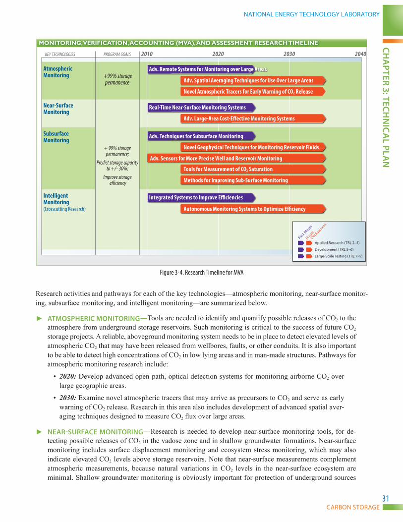
CARBON STORAGE
NATIONAL ENERGY TECHNOLOGY LABORATORYCH
APTER 3: TECH
NIC
AL PLA
N
31
MONITORING, VERIFICATION, ACCOUNTING (MVA), AND ASSESSMENT RESEARCH TIMELINE
2020 20302010 2040KEY TECHNOLOGIES PROGRAM GOALS
+ 99% storage permanence;
Predict storage capacity to +/- 30%;
Improve storage e�ciency
Applied Research (TRL 2–4)
Development (TRL 5–6)
Large-Scale Testing (TRL 7–9)
First M
over
Broad
Deployment
Atmospheric Monitoring
Near-Surface Monitoring
Intelligent Monitoring(Crosscutting Research)
Subsurface Monitoring
+99% storagepermanence Adv. Spatial Averaging Techniques for Use Over Large Areas
Adv. Remote Systems for Monitoring over Large Areas
Adv. Sensors for More Precise Well and Reservoir Monitoring
Adv. Techniques for Subsurface Monitoring
Novel Geophysical Techniques for Monitoring Reservoir Fluids
Integrated Systems to Improve E�ciencies
Real-Time Near-Surface Monitoring Systems
Novel Atmospheric Tracers for Early Warning of CO2 Release
Adv. Large-Area Cost-E�ective Monitoring Systems
Autonomous Monitoring Systems to Optimize E�ciency
Methods for Improving Sub-Surface Monitoring
Tools for Measurement of CO2 Saturation
Figure 3-4. Research Timeline for MVA
Research activities and pathways for each of the key technologies—atmospheric monitoring, near-surface monitor-ing, subsurface monitoring, and intelligent monitoring—are summarized below.
► ATMOSPHERIC MONITORING—Tools are needed to identify and quantify possible releases of CO2 to the atmosphere from underground storage reservoirs. Such monitoring is critical to the success of future CO2 storage projects. A reliable, aboveground monitoring system needs to be in place to detect elevated levels of atmospheric CO2 that may have been released from wellbores, faults, or other conduits. It is also important to be able to detect high concentrations of CO2 in low lying areas and in man-made structures. Pathways for atmospheric monitoring research include:
• 2020: Develop advanced open-path, optical detection systems for monitoring airborne CO2 over large geographic areas.
• 2030: Examine novel atmospheric tracers that may arrive as precursors to CO2 and serve as early warning of CO2 release. Research in this area also includes development of advanced spatial aver-aging techniques designed to measure CO2 flux over large areas.
► NEAR-SURfACE MONITORING—Research is needed to develop near-surface monitoring tools, for de-tecting possible releases of CO2 in the vadose zone and in shallow groundwater formations. Near-surface monitoring includes surface displacement monitoring and ecosystem stress monitoring, which may also indicate elevated CO2 levels above storage reservoirs. Note that near-surface measurements complement atmospheric measurements, because natural variations in CO2 levels in the near-surface ecosystem are minimal. Shallow groundwater monitoring is obviously important for protection of underground sources

U.S. DEPARTMENT OF ENERGY
TECHNOLOGY PROGRAM PLAN
CHA
PTER
3: T
ECH
NIC
AL
PLA
N
32
of drinking water. Techniques are needed for monitoring large areas associated with CO2 storage projects. Pathways for near-surface monitoring research include:
• 2020: Develop real-time monitoring systems for measuring CO2 at the surface, in the unsaturated zone, and in shallow groundwater. Measurement of gas concentrations and biological changes at the surface and in the shallow subsurface, using geophysical methods and other approaches, are included in this research area. Techniques to measure land surface deformation that may result from CO2 movement in the subsurface are also included.
• 2030: Develop advanced systems for measuring near-surface manifestations of CO2 movement and release.
► SUBSURfACE MONITORING—Development of subsurface monitoring tools is a key research area. Such tools are needed to: (1) track the movement of the injected CO2 plume through the storage reservoir, (2) de-fine the lateral extent and boundaries of the plume, (3) track associated pressure changes and other physical property changes in the reservoir, to identify possible release pathways that will inform future monitoring ef-forts, and (4) demonstrate long-term stability of the CO2 plume. Carbon dioxide measurement is straightfor-ward near the injection well, but it becomes more challenging and expensive to perform these measurements over a large area typical of a geologic storage project. Technologies developed should be able to sense small changes from background concentrations. Research pathways for subsurface monitoring research include:
• 2020: Develop methods for improved geophysical imaging and detection of the CO2 plumes; spe-cialized subsurface sensors; and methods to distinguish between pressure front, brine front, and plume front. Development of long-term monitoring tools that can withstand long-term exposure to subsurface conditions is also included in this research area.
• 2030: Research is also needed to develop and test novel geophysical approaches that utilize long-term and permanent tools for direct and indirect measurements of CO2 saturation and employ high-resolution and cost-effective monitoring. Projects to develop advanced data analysis and modelling methods for distinguishing pressure front, brine front, and CO2 plume front are also included in this research area.
► INTELLIGENT MONITORING—Develop and establish intelligent monitoring systems that combine real-time data collection, site-specific and project-specific data analysis and interpretation, and injection control. Such systems need to integrate diverse data from atmospheric, near-surface, and subsurface monitoring networks and convert these data into meaningful and actionable information. Data processing, analysis, and interpretation workflows must be developed that address the particular needs and objectives of an in-dividual storage project. Information delivery and advanced visualization are important components of this key technology. Research pathways include:
• 2020: Create advanced, integrated measurement and control systems to track CO2 before, during, and after injection and improve injection efficiency.
• 2030: Develop high-resolution, robust, permanently installed monitoring networks. Such networks may use autonomous measurement and control systems that integrate atmospheric, near-surface, and subsurface data into reservoir simulations in real time. Such systems may include advanced sensors, high-capacity data transmission, and advanced visualization.
CARBON STORAGE
NATIONAL ENERGY TECHNOLOGY LABORATORYCH
APTER 3: TECH
NIC
AL PLA
N
33
3.3 CARBON USE AND REUSE (CORE R&D)
3.3.1 BACKGROUND/TECHNICAL DISCUSSION
Although the general consensus is that permanent CO2 storage in geologic formations is a promising option for reducing CO2 emissions, this approach may not be viable for all CO2 emitters. For some, the added cost of capture may be too high to implement or the geology in proximity to the source may not be suitable for geologic storage. In these circumstances, other options will be needed.
At this time, the most significant utilization for CO2 is in EOR operations, which is the focus of many first mover projects. The United States is fortunate to have a long history of oil production over the past 100 years, as well as more than 40 years of EOR utilizing CO2. There is an opportunity to supplement—and eventually replace—the naturally occurring CO2 used for EOR with CO2 from anthropogenic sources, thus reducing the carbon footprint of these fuels and the nation’s dependency on foreign oil imports.
Research within the Carbon Use and Reuse Technology Areas is focused on using CO2 as a feedstock in a variety of ways. The current global market for bulk CO2 is small and most applications do not account for its ultimate fate. CO2 use and reuse will not replace geologic storage, but complement the efforts to offset the cost of capture.
3.3.2 CARBON USE AND REUSE R&D APPROACH
While CO2 is thermodynamically stable, it is still reactive under certain conditions that do not necessarily require intensive energy input. Therefore, using CO2 as a feedstock for a variety of products is promising, particularly in conjunction with energy generated from renewable energy sources during off-peak hours. The Carbon Use and Reuse Technology Area seeks to support the development of technologies identified as having the greatest potential to help boost the commodity market for CO2 while producing no additional CO2 emissions. Doing this will require a compre-hensive understanding of product markets, in addition to their conventional energy balances and life cycles. Figure 3-5 illustrates most of the current and potential uses of CO2. However, many of these uses are small-scale and typically emit the CO2 to the atmosphere after use, resulting in no reduction in overall CO2 emissions. Some of the more sig-nificant current and potential uses of CO2 are highlighted in the DOE-sponsored research within this Technology Area.
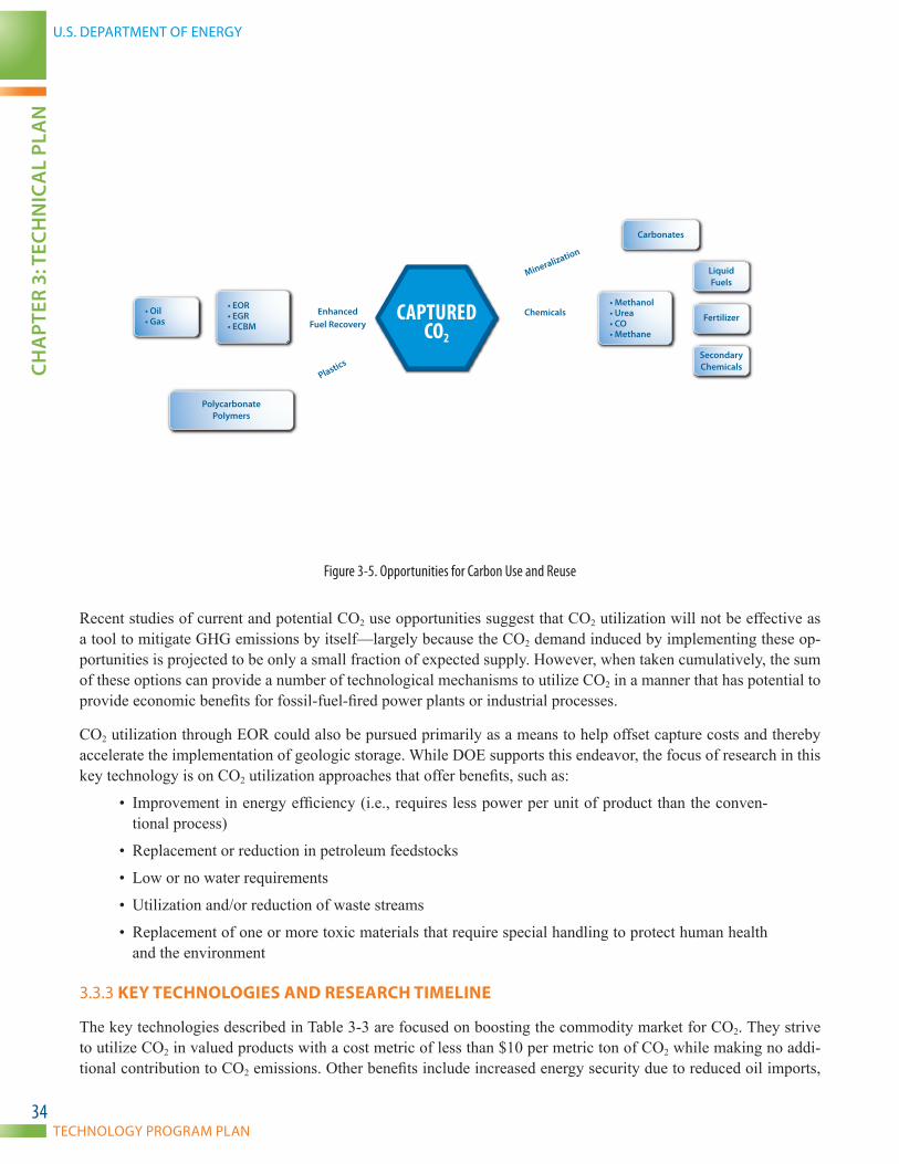
U.S. DEPARTMENT OF ENERGY
TECHNOLOGY PROGRAM PLAN
CHA
PTER
3: T
ECH
NIC
AL
PLA
N
34
Carbonated Beverages
Fuels Food
• Algae• Greenhouse Gases
• Flavors/Fragrances• Decaffeination
• Refrigeration• Dry Ice
• Injected into Metal Castings• Respiratory Stimulant (Added to Medical O2)• Aerosol Can Propellant• Dry Ice Pellets Used for Sand Blasting• Red Mud Carbonation
• Blanket Products• Protection for Carbon Powder• Shield Gas in Welding
Fire Extinguishers
Food/Products
Conv
ersi
on
Extractant
Refrigerant
MiscellaneousA
gent
Iner
ting
Fire Supre
ssio
n
Biol
ogic
al
CAPTUREDCO2
Carbonates
Liquid Fuels
• Methanol• Urea• CO• Methane
Fertilizer
Secondary Chemicals
Polycarbonate Polymers
• EOR• EGR• ECBM
• Oil• Gas
Mineralization
Chemicals
Plastics
EnhancedFuel Recovery
Figure 3-5. Opportunities for Carbon Use and Reuse
Recent studies of current and potential CO2 use opportunities suggest that CO2 utilization will not be effective as a tool to mitigate GHG emissions by itself—largely because the CO2 demand induced by implementing these op-portunities is projected to be only a small fraction of expected supply. However, when taken cumulatively, the sum of these options can provide a number of technological mechanisms to utilize CO2 in a manner that has potential to provide economic benefits for fossil-fuel-fired power plants or industrial processes.
CO2 utilization through EOR could also be pursued primarily as a means to help offset capture costs and thereby accelerate the implementation of geologic storage. While DOE supports this endeavor, the focus of research in this key technology is on CO2 utilization approaches that offer benefits, such as:
• Improvement in energy efficiency (i.e., requires less power per unit of product than the conven-tional process)
• Replacement or reduction in petroleum feedstocks
• Low or no water requirements
• Utilization and/or reduction of waste streams
• Replacement of one or more toxic materials that require special handling to protect human health and the environment
3.3.3 KEY TECHNOLOGIES AND RESEARCH TIMELINE
The key technologies described in Table 3-3 are focused on boosting the commodity market for CO2. They strive to utilize CO2 in valued products with a cost metric of less than $10 per metric ton of CO2 while making no addi-tional contribution to CO2 emissions. Other benefits include increased energy security due to reduced oil imports,

CARBON STORAGE
NATIONAL ENERGY TECHNOLOGY LABORATORYCH
APTER 3: TECH
NIC
AL PLA
N
35
improved balance of payments for international trade, and providing U.S. industry with potentially low-cost options for reducing GHG emissions exists.
Table 3-3. Carbon Use and Reuse Key Technologies Research DescriptionKey Technology DescriptionPolycarbonate Plastics Develop a commercially viable method of using CO2 to make stable polycarbonate plastics.
Mineralization/Cements Develop commercial uses for CO2 in mineralization and cements.
Chemicals Explore the use of CO2 as a feedstock for industrial-scale chemical production.
The timeline in Figure 3-6 shows research pathways for development of advanced Carbon Use and Reuse key technologies from applied research (TRL 2–4), through development (TRL 5–6), to large-scale testing (TRL 7–9). Note that all technologies in the Carbon Use and Reuse Technology Area are considered to be deployed in broad deployment projects, because they all represent major improvements in existing technologies or development of novel methods and approaches. The technologies are expected to be in large-scale testing by 2030, with widespread commercial application by 2035.
CARBON USE AND REUSE RESEARCH TIMELINE
2020 20302010 2040KEY TECHNOLOGIES PROGRAM METRIC
Applied Research (TRL 2–4)
Development (TRL 5–6)
Large-Scale Testing (TRL 7–9)
Broad
Deployment
Polycarbonate Plastics
Chemicals
Mineralization/Cements
Avoid CO2
Emissions at <$10/metric ton
Develop Adv. Catalysts and Stabilizers to Convert CO2 to Plastics
High-Strength Cement, Max. CO2 Uptake, Min. Energy Consumption
Dev. Adv. Catalysts for Conversion of CO2 to Commodity Chem. Utilizing Waste Energy
Figure 3-6. Research Timeline for Carbon Use and Reuse
► POLYCARBONATE PLASTICS—One Carbon Use and Reuse key technology is the fabrication of polycar-bonate plastics. Traditional monomers, such as ethylene and propylene, can be combined with CO2 to produce polycarbonates, such as polyethylene carbonate and polypropylene carbonate. The advantage of this process is that it copolymerizes CO2 directly with other monomers without having to first convert the CO2 to carbon monoxide or some other reactive species, thus significantly reducing energy requirements. There are many potential uses for polycarbonate plastics, including coatings and laminates. Research in this area includes:
• 2030: Develop advanced catalysts and stabilizers to convert CO2 to plastics. These projects may utilize waste energy or alternative energy sources to convert CO2.
► MINERALIZATION AND CEMENTS—A second Carbon Use and Reuse key technology is mineralization and cements. Carbonate mineralization is the conversion of CO2 to solid inorganic carbonates. Naturally occurring alkaline and alkaline-earth oxides react chemically with CO2 to produce minerals, such as cal-cium carbonate and magnesium carbonate. Curing concrete and concrete-like materials with CO2 has the potential to reduce curing time, use less energy, and enhance mechanical properties while consuming CO2 in the process. The transition from demonstration and commercial scale may be accelerated because modi-fications to an existing curing process would be extensive. Research includes:
U.S. DEPARTMENT OF ENERGY
TECHNOLOGY PROGRAM PLAN
CHA
PTER
3: T
ECH
NIC
AL
PLA
N
36
• 2030: Develop methods to convert CO2 to solid, inorganic minerals, such as calcium carbonate and magnesium carbonate and develop high strength cement that meets or exceeds industry standards. Use of CO2 in the cement curing process has the potential to reduce curing time and enhance me-chanical properties of the cement, while simultaneously consuming CO2.
► CHEMICALS—Finally, research is needed to develop other chemical uses of CO2. If CO2 were available as a plentiful and inexpensive feedstock, it could offer industry opportunities to develop more efficient, less costly, and safer manufacturing processes compared to conventional manufacturing. Greater energy efficiency, along with consumption of CO2 in the process, could make this a viable alternative and reduce net emissions. Research includes:
• 2030: Develop advanced catalysts and more efficient manufacturing processes for converting CO2 to valuable chemicals. Research will focus on integrating waste energy or alternative energy sources into the process.
3.4 INFRASTRUCTURE (REGIONAL CARBON SEQUESTRATION PARTNERSHIPS)
3.4.1 BACKGROUND/TECHNICAL DISCUSSION
DOE determined early in the program’s development that addressing CO2 mitigation from power and industrial sources regionally would be the most effective way to address differences in geology, climate, population density, oil and gas infrastructure, human capital, and socioeconomic development throughout the United States. To support the development of regional infrastructure for CCS, this Technology Area consists of several efforts, including:
• National efforts to characterize storage formations and reduce uncertainty associated with storage resource estimates.
• Implementing small- and large-scale CO2 field projects in different geologic formation classes rep-resenting various depositional environments.
• Development of geologic storage BPMs to communicate lessons learned from field projects to industry, regulators, and the public.
• Supporting the development of human capital, stakeholder networking, regulatory policy develop-ment, carbon mitigation plans, and public outreach and education throughout the United States.
The Infrastructure Technology Area research effort is carrying out regional characterization and small- and large-scale field projects to demonstrate that different storage types in various formation classes, distributed over different geographic regions, both onshore and offshore, have the capability to permanently store CO2 and provide the basis for commercial-scale CO2 projects. Research is needed to prove adequate injectivity, available storage resource, and storage permanence across the range of formation classes and storage types. Small- and large-scale field tests are needed to validate injection, simulation/risk assessment, and monitoring strategies, as well as determine the systems best suited for the particular geologic structure, reservoir architecture, and range of properties characteristic of each geologic formation class.
DOE has created a network of seven RCSPs (Figure 3-7) to help carry out research efforts in the Infrastructure Technology Area. The RCSP Initiative is being implemented in the following three phases:
• Characterization Phase (2003–2005): Initial characterization of their region’s potential to store CO2 in different geologic formations.
• Validation Phase (2005–2013): Validation of the most promising regional storage opportunities through a series of small-scale field projects.

CARBON STORAGE
NATIONAL ENERGY TECHNOLOGY LABORATORYCH
APTER 3: TECH
NIC
AL PLA
N
37
• Development Phase (2008–2018+): Implementation of large-scale field testing involving at least 1 million metric tons of CO2 per project to confirm that CO2 injection and storage can be achieved safely, permanently, and economically.
BSCSP – Big Sky Carbon Sequestration PartnershipMGSC – Midwest Geological Sequestration ConsortiumMRCSP – Midwest Regional Carbon Sequestration PartnershipPCOR – The Plains CO2 Reduction PartnershipSECARB – Southeast Regional Carbon Sequestration PartnershipSWP – Southwest Partnership on Carbon SequestrationWESTCARB – West Coast Regional Carbon Sequestration Partnership
MRCSPMGSC
SECARB
PCORBSCSP
WESTCARB
SWP
Figure 3-7. Regional Carbon Sequestration Partnership Regions
In conjunction with the RCSPs and others, DOE/NETL is also investigating the challenges and benefits associated with building a national CO2 pipeline network, including developing models to map pipeline scenarios so that cost estimates and regional differences can be identified and stakeholders can have a blueprint for future decades. Chal-lenges associated with CO2 transportation include:
• Regulatory uncertainty and public perception
• Economic feasibility
• Liability risks
• Large-scale integration of pipeline networks
• Corrosion-resistant alloys and coatings

U.S. DEPARTMENT OF ENERGY
TECHNOLOGY PROGRAM PLAN
CHA
PTER
3: T
ECH
NIC
AL
PLA
N
38
DOE/NETL is conducting regional case studies to determine theoretical pipeline routes that could efficiently trans-port CO2 from stationary sources to nearby viable geologic storage sites. The implications of economics, resources, and timing of pipeline development are being evaluated to provide the basis for better estimates of the potential impacts and costs associated with a nationwide pipeline network.
3.4.2 INFRASTRUCTURE KEY TECHNOLOGIES R&D APPROACH
Each type of geologic formation has different opportunities and challenges. While geologic formations are infinitely variable in detail, they have been classified by geologists and engineers in the petroleum industry by their trapping mechanism, the hydrodynamic conditions (mechanical forces that produce), lithology (physical characteristics), and more recently by their depositional environment (how they were formed). The depositional environment influ-ences how formation fluids are held in place, how they move, and how they interact with other formation fluids and solids (minerals). These properties may allow the formation to be labeled as a reservoir, which in a broad sense permit the containment of liquids or gases. For the purpose of geologic storage, the geologic formation/reservoir classification system has been adapted to include unconventional reservoirs, such as coalbeds, organic shale, and igneous formations (stacked basalts). By understanding the depositional environments of potential reservoirs, cor-relations can be drawn from similar depositional environments around the world. This could potentially eliminate some of the site-specific characterization requirements for similar depositional systems.
DOE’s program goals involve identification of geologic formations that can store large volumes of CO2, receive and inject these volumes at an efficient and economic rate, and safely retain the CO2 over long time periods.
The effectiveness of CO2 injection and storage operations and the ability of technologies to monitor and simu-late CO2 storage will differ among geologic formation classes. Additional work is needed to understand how the chemical effect of fluids (water, oil, and gas) and reservoir rock, geomechanical properties, compartmentalization, heterogeneity, potential microseismicity, and reservoir architecture impact storage of CO2 and other impurities that might be present in the injection stream. There are 11 different classes of geologic storage formations (deltaic, shelf clastic, shelf carbonate, strandplain, reef, lacustrine, eolian, fluvial and alluvial, turbidite, coal, and basalt) and two different classes of seals (shale and evaporites1) that need to be considered when developing future field projects, in both onshore and offshore environments.
Therefore, the Infrastructure Technology Area, supported by the CCRP, is organized into validating storage in four key technologies:
► CLASTICS (DELTAIC, LACUSTRINE, FLUVIAL AND ALLUVIAL, STRANDPLAIN, TURBIDITE, EOLIAN, AND SHELF CLASTIC)—These deposits can form fans, sand bars, deltas, braided or meandering streams, or dunes, each having a distinct depositional pattern and a unique internal architecture that controls fluid flow within the reservoir body. Understanding the flow of CO2 in these different formations and any post-depositional processes is critical to determining the technology and protocols necessary to comply with the EPA Class VI and GHG reporting rules.
► CARBONATES (SHELF CARBONATE AND REEF)—These formations are the product of both biological and chemical depositional systems (e.g., corals formed in reefs, oyster shell banks, or as chemical precipitates). Carbonate sediments formed in oceans are the result of tiny shells drifting down and accumulating as thick ooze on the seafloor. The ooze is transformed into carbonate shale or chalk over time. Water has reacted with carbonate rocks in some areas to create porosity and permeability (solution channels), making these rocks of interest for CCS. Storage in these formations requires understanding of the development of these channels, geochemistry, and impacts of hydrologic boundary conditions (whether the system is open or confined).
1 Evaporites are rocks—such as salt, gypsum, and anhydrite—that formed when saline water evaporated, leaving layers of dense, low-permeability salts.

CARBON STORAGE
NATIONAL ENERGY TECHNOLOGY LABORATORYCH
APTER 3: TECH
NIC
AL PLA
N
39
► COAL AND SHALE (NOTE THAT SHALE IS ALSO A COMMON SEAL FOR A STORAGE RESERVOIR)—Coals and shales of interest for storage are formed from deposits of high-organic materials. Both have much lower permeability than clastics but may offer opportunities for a more secure form of storage along with enhanced natural gas recovery. In both coal and organic shale, CO2 will preferentially absorb to mineral surfaces, releasing methane, while permanently locking the CO2 in place.
► BASALT—Basalt is produced when magma exits and cools quickly outside of, or near, the Earth’s surface. The rapid cooling means that mineral crystals do not have much time to grow, so these rocks are fine-grained. At the top of flows, hot gas bubbles are often trapped in quenched lava, forming a bubbly, vesicular texture having substantial porosity, offering the opportunity for CO2 storage. Challenges including effective permea-bility, containment, and fast chemical reaction rates with CO2 make testing storage in basalt a key technology.
The research is focused on the characterization of the geology throughout the United States and the implementation of small- and large-scale field projects to validate the appropriate technologies that should be deployed at each site.
Evaluation of the geology and depositional environments through laboratory testing and small- and large-scale field projects is critical across these storage formation classes and seals to validate that the geology of the United States is available for large-scale CCS development. Efforts like the RCSPs and other small- and large-scale field projects are critical to enhancing the nation’s knowledge and understanding of which systems will be available for CCS deployment in the future. Table 3-4 provides a summary of DOE-supported field projects that are assessing the dif-ferent geologic storage classes. This information will be used to identify future research efforts to better understand storage in these different geologic storage formation classes.
Table 3-4. Matrix of Field Activities in Different Reservoir Classes (2012)1
Geologic Storage Formation Classification: Reservoir Class
Delta
ic
Shelf
Clas
tic
Stra
ndpl
ain
Lacu
strin
e
Eolia
n
Fluvia
l and
Al
luvia
l
Turb
idite
Shelf
Carb
onat
e
Reef
Coal/
Shale
Basa
lt (la
rge
igne
ous
prov
ince
s)
Large-Scale Field Projects2
Saline 3 1
EOR 1 24 1
Small-Scale Field Projects3
Saline 1 1 1 2 1
EOR 2 2 1 3 2 7
NOTES:(1) The number in the cell is the number of investigations by NETL per geologic storage formation classification.(2) Large-scale field projects: injection of more than 1,000,000 metric tons of CO2.(3) Small-scale field projects: injection of less than 500,000 metric tons of CO2 for EOR and 100,000 metric tons for saline formations.
Site characterization: characterize the subsurface at a location with the potential to inject at least 30,000,000 metric tons of CO2.(4) One large-scale project involves both EOR and saline storage.
SMALL-SCALE CO2 INJECTION PROJECTS
DOE has conducted and continues to support a number of small-scale field projects (injection of less than 500,000 metric tons of CO2 per year) to explore and characterize CO2 storage opportunities in North America (Figure 3-8). DOE’s small-scale field test efforts are designed to demonstrate that regional storage formations have the capability to store CO2 and provide the foundation for larger volume, commercial-scale projects. The field projects are focused on developing a better understanding of the 11 major types of geologic storage reservoir classes. Understanding these different storage classes provides insight into how the systems influence fluid flow within these systems. These storage reservoirs contain fluids that may include natural gas, oil, or saline water—any of which may impact CO2 storage. The data gathered during these small-scale projects provide valuable information regarding specific formations that have not been evaluated for the purpose of CO2 storage. The Carbon Storage program strategy in-cludes an established set of field-test objectives applicable to all of the small-scale injection projects:
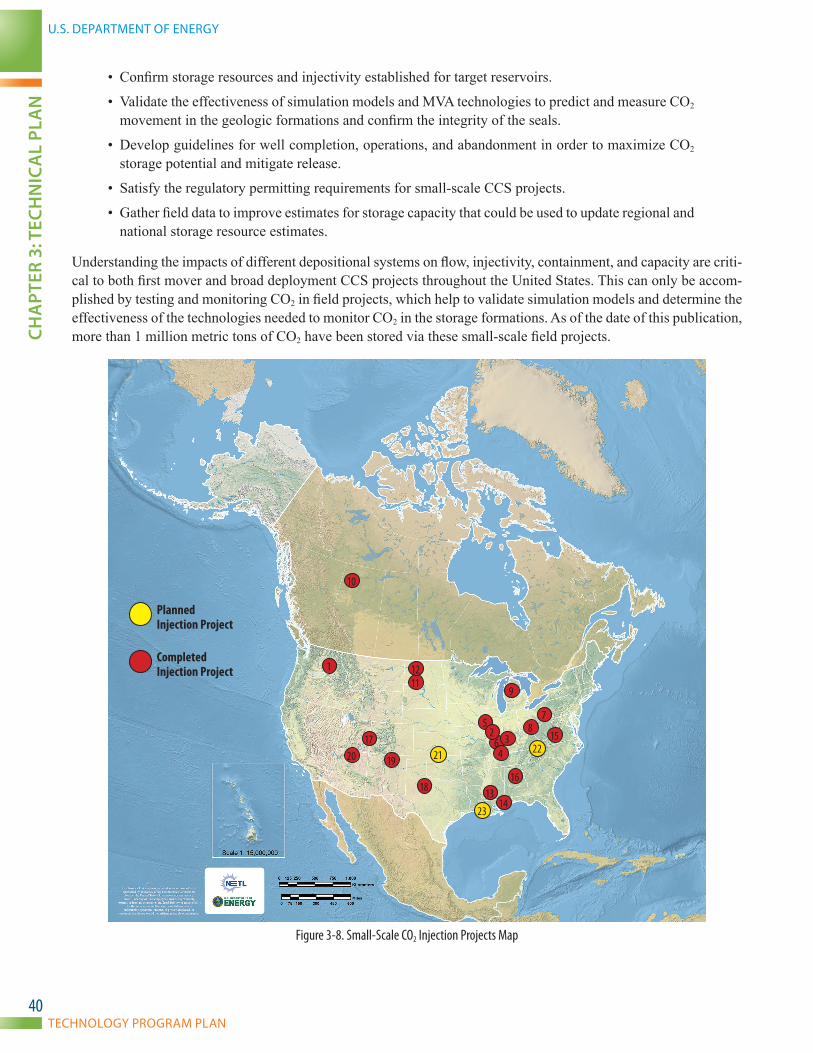
U.S. DEPARTMENT OF ENERGY
TECHNOLOGY PROGRAM PLAN
CHA
PTER
3: T
ECH
NIC
AL
PLA
N
40
• Confirm storage resources and injectivity established for target reservoirs.
• Validate the effectiveness of simulation models and MVA technologies to predict and measure CO2 movement in the geologic formations and confirm the integrity of the seals.
• Develop guidelines for well completion, operations, and abandonment in order to maximize CO2 storage potential and mitigate release.
• Satisfy the regulatory permitting requirements for small-scale CCS projects.
• Gather field data to improve estimates for storage capacity that could be used to update regional and national storage resource estimates.
Understanding the impacts of different depositional systems on flow, injectivity, containment, and capacity are criti-cal to both first mover and broad deployment CCS projects throughout the United States. This can only be accom-plished by testing and monitoring CO2 in field projects, which help to validate simulation models and determine the effectiveness of the technologies needed to monitor CO2 in the storage formations. As of the date of this publication, more than 1 million metric tons of CO2 have been stored via these small-scale field projects.
1
Planned Injection Project
Completed Injection Project 1
6
78
9
10
1112
13
34
14
15
16
17
18
1920 21 22
23
52
Figure 3-8. Small-Scale CO2 Injection Projects Map

CARBON STORAGE
NATIONAL ENERGY TECHNOLOGY LABORATORYCH
APTER 3: TECH
NIC
AL PLA
N
41
Table 3-5. Small-Scale CO2 Injection Project Details
Number on Map Project Name RCSP/State Project Type Injection Formations (Reservoir)CO2 Injected
(metric tons) April 2012
1 Wallula Basalt Pilot Study BSCSP Basalt Interflow Zones, Grande Ronde Basalt 1,000*
2 Loudon Single Well Huff N Puff Project MGSC HNP Cypress and Mississippi Weiler SS 39
3 Mumford Hills Project MGSC EOR Clore Sandstone 6,300
4 Sugar Creek Project MGSC EOR Jackson Sandstone 6,560
6 Tanquary Well Project MGSC ECBM Springfield Coal 91
7 Appalachian Basin Geologic Test at R.E. Burger Power Plant: Fegenco Well MRCSP Saline Clinton SS/Salina Fm/Oriskany SS 50
8 Duke Energy—East Bend Well Site MRCSP Saline Mt. Simon 910
9 Michigan Basin Geologic Test MRCSP Saline Bass Islands Dolomite 60,000
10 Zama Acid Gas EOR, CO2 Storage, and Monitoring Project PCOR EOR Middle Devonian Keg River Formation 133,550
acid gas
11 NW McGregor EOR HNP Project PCOR EOR/HNP Mission Canyon Limestone 400
12 Lignite CCS Project PCOR ECBM Lignite Seams in Ft. Union Formation 80
13 Gulf Coast Stacked Storage Project SECARB EOR Tuscaloosa Formation 627,744
14 Plant Daniel Project SECARB Saline Massive Sand, Lower Tuscaloosa 2,740
15 Central Appalachian Basin Coal Test SECARB ECBM Pocahontas and Lee Formation 907
16 Black Warrior Project SECARB ECBM Pottsville Formation (coal zones) 252
17 Aneth EOR Sequestration Test SWP EOR Desert Creek and Ismay Formation 292,000
18 SACROC CO2 Injection Project SWP EOR Horseshoe Atoll and Pennsylvanian Reef/Bank Play 157,000
19 Pump Canyon CO2-ECBM/Sequestration Demonstration SWP ECBM Fruitland Coal Formation 16,700
20 Arizona Utilities CO2 Storage Pilot WESTCARB Saline Martin and Naco Formations *
Northern California Geologic Characterization WESTCARB Geologic
CharacterizationDomengine, Mokelumne River, H&T/Starkey SS *
21 University of Kansas Center for Research, Inc. Kansas Multiple
Formations Arbuckle 70,000*
22 Virginia Polytechnic Institute and State University Virginia ECBM Appalachian Basin; Sourwood or Oakwood
CBM Fields 20,000*
23 Blackhorse Energy, LLC Louisiana EOR Gulf Coast Basin; First Wilcox Sand 53,000*
* Planned* 5 MGSC’s Project #5 (Illinois Basin) was changed to a large-scale injection.

U.S. DEPARTMENT OF ENERGY
TECHNOLOGY PROGRAM PLAN
CHA
PTER
3: T
ECH
NIC
AL
PLA
N
42
LARGE-SCALE CO2 INJECTION PROJECTS
DOE is supporting, through the RCSP Development Phase, large-scale field projects in different geological storage classes to confirm that CO2 capture, transportation, injection, and storage can be achieved safely, permanently, and economically (Figure 3-9). Results from these projects will provide a more thorough understanding of migration and permanent storage of CO2 within various reservoir classes of geologic storage formations, which will help sup-port regulatory development and industry in commercialization and deployment of CCS. The storage types and for-mations being tested are considered regionally significant and are expected to have the potential to store hundreds of years of CO2 from stationary source emissions. As of August 2013, approximately 4 million metric tons of CO2 have been stored in various geologic formations via the large-scale field projects being developed by the RCSPs.
1
2
34
5
6 7
8
Injection Ongoing
2014/2015 Injection Scheduled
Figure 3-9. Large-Scale CO2 Injection Projects Map

CARBON STORAGE
NATIONAL ENERGY TECHNOLOGY LABORATORYCH
APTER 3: TECH
NIC
AL PLA
N
43
Table 3-6. Large-Scale CO2 Injection Project DetailsNumber on Map RCSP Geologic Province
1 BSCSP Kevin Dome—Duperow Formation
2 MGSC Illinois Basin—Mt. Simon Sandstone
3 MRCSP Michigan Basin—Niagaran Reef
4PCOR
Powder River Basin—Muddy Sandstone
5 Horn River Basin—Sulphur Point Formation
6SECARB
Gulf Coast—Tuscaloosa Formation
7 Gulf Coast—Citronelle—Paluxy Formation
8 SWP Anadarko Basin—Morrow Sandstone
--- WESTCARB Regional Characterization
In the near term, large-scale projects will support and validate the industry’s ability to ensure storage permanence in reservoirs in different depositional environments supporting first mover projects. Specifically, large-scale field projects will continue to address practical issues, such as sustainable injectivity, well design for integrity, storage resource utilization (utilization of pore space and oil and gas recovery), and reservoir behavior—with respect to prolonged injection. Complete assessments of these issues are necessary to validate and improve model predictions concerning the behavior of injected CO2 at scale, establish the engineering and scientific processes for successfully implementing and validating safe long-term storage, and achieve cost-effective integration with power plants and other large industrial emission sources for carbon capture.
The large-scale field projects are implemented in three stages and typically require 10 years to implement. These three stages include the site characterization, injection operations, and post-injection monitoring. In order to vali-date that CCS can be conducted at commercial scale, a number of key research pathways are being pursued by each of the large-scale projects:
• Prove adequate injectivity and available capacity at pre-commercial scale.
• Prove storage permanence by validating that CO2 will be retained in the subsurface, and that proj-ects do not adversely impact underground sources of drinking water and/or cause CO2 to be released to the atmosphere, while also developing technologies and protocols to quantify potential releases.
• Determine the areal extent of the CO2 plume/pressure front and potential release pathways by mon-itoring the areal and vertical migration of the CO2 during and after project completion and develop methodologies to determine the presence/absence of release pathways.
• Develop risk assessment strategies by identifying risk parameters, probability and potential impact of occurrences, and mitigation strategies for each field site.
• Engage in the development of an effective regulatory and legal framework for the safe injection and long-term geologic CO2 storage in the regions where the projects are developed.
Results obtained from these efforts will provide the foundation for validating that CCS technologies can be com-mercially deployed and monitored throughout the United States. These and future large-scale projects will be neces-sary to validate storage projects integrated with carbon capture technologies from various CO2 sources and geologic storage in all storage formation types in multiple basins throughout the United States.
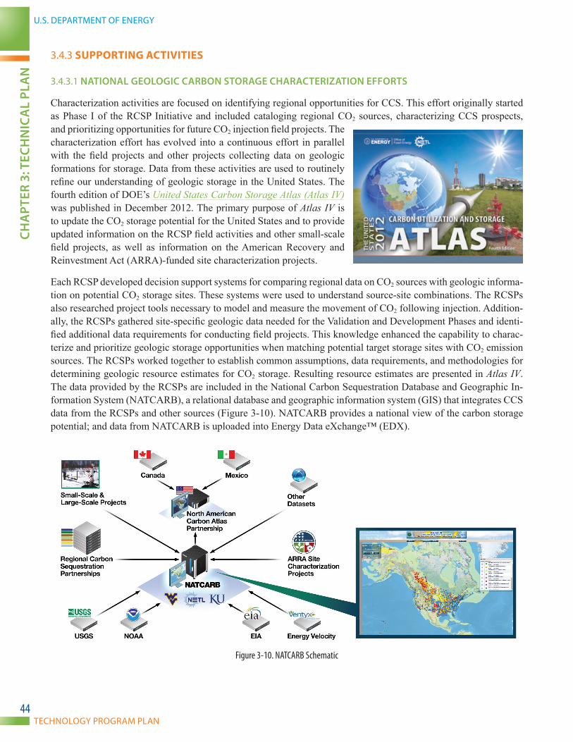
U.S. DEPARTMENT OF ENERGY
TECHNOLOGY PROGRAM PLAN
CHA
PTER
3: T
ECH
NIC
AL
PLA
N
44
3.4.3 SUPPORTING ACTIVITIES
3.4.3.1 NATIONAL GEOLOGIC CARBON STORAGE CHARACTERIZATION EffORTS
Characterization activities are focused on identifying regional opportunities for CCS. This effort originally started as Phase I of the RCSP Initiative and included cataloging regional CO2 sources, characterizing CCS prospects, and prioritizing opportunities for future CO2 injection field projects. The characterization effort has evolved into a continuous effort in parallel with the field projects and other projects collecting data on geologic formations for storage. Data from these activities are used to routinely refine our understanding of geologic storage in the United States. The fourth edition of DOE’s United States Carbon Storage Atlas (Atlas IV) was published in December 2012. The primary purpose of Atlas IV is to update the CO2 storage potential for the United States and to provide updated information on the RCSP field activities and other small-scale field projects, as well as information on the American Recovery and Reinvestment Act (ARRA)-funded site characterization projects.
Each RCSP developed decision support systems for comparing regional data on CO2 sources with geologic informa-tion on potential CO2 storage sites. These systems were used to understand source-site combinations. The RCSPs also researched project tools necessary to model and measure the movement of CO2 following injection. Addition-ally, the RCSPs gathered site-specific geologic data needed for the Validation and Development Phases and identi-fied additional data requirements for conducting field projects. This knowledge enhanced the capability to charac-terize and prioritize geologic storage opportunities when matching potential target storage sites with CO2 emission sources. The RCSPs worked together to establish common assumptions, data requirements, and methodologies for determining geologic resource estimates for CO2 storage. Resulting resource estimates are presented in Atlas IV. The data provided by the RCSPs are included in the National Carbon Sequestration Database and Geographic In-formation System (NATCARB), a relational database and geographic information system (GIS) that integrates CCS data from the RCSPs and other sources (Figure 3-10). NATCARB provides a national view of the carbon storage potential; and data from NATCARB is uploaded into Energy Data eXchange™ (EDX).
Figure 3-10. NATCARB Schematic
CARBON STORAGE
NATIONAL ENERGY TECHNOLOGY LABORATORYCH
APTER 3: TECH
NIC
AL PLA
N
45
The efforts of the RCSPs and other large- and small-scale projects have substantially increased the knowledge base regarding the potential to use different formations, not previously explored for oil and gas, as storage reservoirs for CO2. Yet, a lack of information still exists on storage formations throughout North America. The RCSPs continu-ously support efforts by research organizations, State geologic surveys, and industry to gather existing data and collect new information for all storage types. This will help to reduce the uncertainty associated with CO2 storage resource estimates, improve the nation’s understanding of storage efficiency, and allow for a better understanding of injectivity rates and the performance and extent of regional seals needed to contain the CO2.
The characterization effort focuses on value-added reservoirs that can support the deployment of CCS technologies by industry in onshore and offshore settings. These efforts will include refinements in the technical methodology used to assess regionally important formations. The additional efforts will build upon the data previously collected by the RCSPs and work with industry, the Bureau of Ocean Energy Management (BOEM), and the State geologic surveys to collect additional data on key formations.
For example, an offshore study to investigate the potential for permanent underground storage of CO2 in geologic formations was launched by the University of Texas at Austin via the Bureau of Economic Geology in the United States through ARRA funding. The 3-year project is designated to identify State-owned areas underlying the Gulf where CO2 can be stored safely and economically.
Another outer continental shelf study underway in the Los Angeles Basin presents a unique opportunity for large-scale offshore geologic storage of CO2. This research project has the objective to characterize Pliocene and Miocene sediments within the Wilmington Graben (located offshore Los Angeles, CA) for high-volume CO2 storage oppor-tunities. Other storage formations off the coasts of Oregon, Washington, and Alaska have also been screened and assessed. These screened saline formations, both offshore and onshore, have storage potential, but volumes have not been estimated due to insufficient data. Therefore, these formations require further evaluation. In Alaska, critical constraining data for developing volumetric CO2 storage estimates are typically sparse or lacking.
In the eastern States, sedimentary deposits in the coastal plain along the continental shelf are also being considered for potential CO2 storage. MRCSP began preliminary characterization of potential reservoirs and confining units in the New Jersey continental shelf by utilizing existing well logs from the outer continental shelf and continental slope, acquired well paleontology data, as well as newly scanned multichannel seismic data from older seismic profiles in the offshore region.
The current estimates for CO2 storage resources are not restricted by economic or social constraints (Figure 3-11). Future efforts will begin to consider how commercial facilities will need to operate and the minimum reservoir con-ditions and demographic requirements needed to develop commercial projects. In addition, CO2 storage resources will continue to be refined as future storage projects systematically move through a project maturation process as defined in DOE’s BPM for site screening, site selection, and initial characterization. These efforts will provide considerably improved data and methodologies for determining national estimates, as well as specific estimates for projects developed in different geologic basins of the United States.
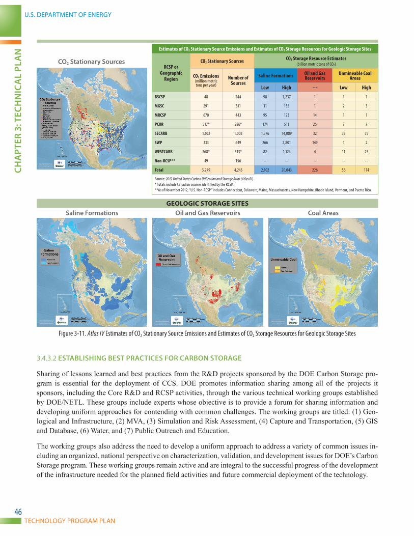
U.S. DEPARTMENT OF ENERGY
TECHNOLOGY PROGRAM PLAN
CHA
PTER
3: T
ECH
NIC
AL
PLA
N
46
Estimates of CO2 Stationary Source Emissions and Estimates of CO2 Storage Resources for Geologic Storage Sites
RCSP or Geographic
Region
CO2 Stationary Sources CO2 Storage Resource Estimates(billion metric tons of CO2)
CO2 Emissions (million metric tons per year)
Number of Sources
Saline Formations Oil and Gas Reservoirs
Unmineable Coal Areas
Low High --- Low High
BSCSP 48 244 98 1,237 1 1 1
MGSC 291 311 11 158 1 2 3
MRCSP 670 443 95 123 14 1 1
PCOR 517* 926* 174 511 25 7 7
SECARB 1,103 1,003 1,376 14,089 32 33 75
SWP 333 649 266 2,801 149 1 2
WESTCARB 268* 513* 82 1,124 4 11 25
Non-RCSP** 49 156 -- -- -- -- --
Total 3,279 4,245 2,102 20,043 226 56 114
Source: 2012 United States Carbon Utilization and Storage Atlas (Atlas IV) * Totals include Canadian sources identified by the RCSP. **As of November 2012, “U.S. Non-RCSP” includes Connecticut, Delaware, Maine, Massachusetts, New Hampshire, Rhode Island, Vermont, and Puerto Rico.
CO2 Stationary Sources
GEOLOGIC STORAGE SITESSaline formations Oil and Gas Reservoirs Coal Areas
Figure 3-11. Atlas IV Estimates of CO2 Stationary Source Emissions and Estimates of CO2 Storage Resources for Geologic Storage Sites
3.4.3.2 ESTABLISHING BEST PRACTICES fOR CARBON STORAGE
Sharing of lessons learned and best practices from the R&D projects sponsored by the DOE Carbon Storage pro-gram is essential for the deployment of CCS. DOE promotes information sharing among all of the projects it sponsors, including the Core R&D and RCSP activities, through the various technical working groups established by DOE/NETL. These groups include experts whose objective is to provide a forum for sharing information and developing uniform approaches for contending with common challenges. The working groups are titled: (1) Geo-logical and Infrastructure, (2) MVA, (3) Simulation and Risk Assessment, (4) Capture and Transportation, (5) GIS and Database, (6) Water, and (7) Public Outreach and Education.
The working groups also address the need to develop a uniform approach to address a variety of common issues in-cluding an organized, national perspective on characterization, validation, and development issues for DOE’s Carbon Storage program. These working groups remain active and are integral to the successful progress of the development of the infrastructure needed for the planned field activities and future commercial deployment of the technology.
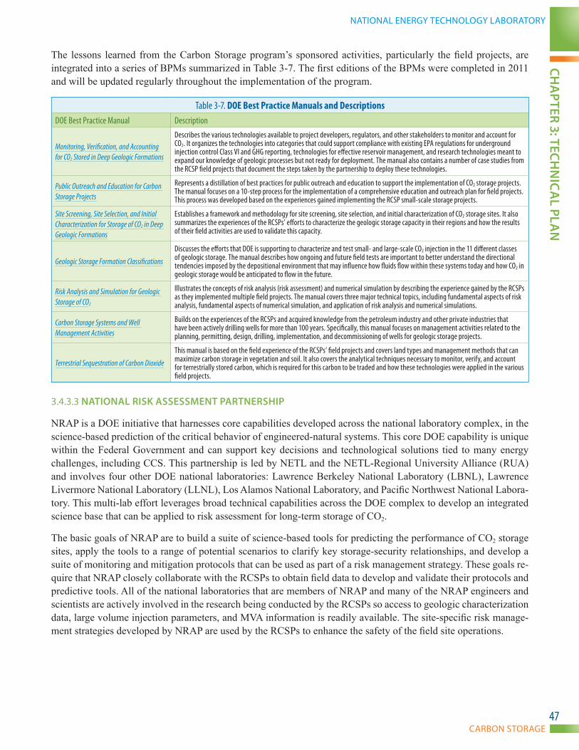
CARBON STORAGE
NATIONAL ENERGY TECHNOLOGY LABORATORYCH
APTER 3: TECH
NIC
AL PLA
N
47
The lessons learned from the Carbon Storage program’s sponsored activities, particularly the field projects, are integrated into a series of BPMs summarized in Table 3-7. The first editions of the BPMs were completed in 2011 and will be updated regularly throughout the implementation of the program.
Table 3-7. DOE Best Practice Manuals and DescriptionsDOE Best Practice Manual Description
Monitoring, Verification, and Accounting for CO2 Stored in Deep Geologic Formations
Describes the various technologies available to project developers, regulators, and other stakeholders to monitor and account for CO2. It organizes the technologies into categories that could support compliance with existing EPA regulations for underground injection control Class VI and GHG reporting, technologies for effective reservoir management, and research technologies meant to expand our knowledge of geologic processes but not ready for deployment. The manual also contains a number of case studies from the RCSP field projects that document the steps taken by the partnership to deploy these technologies.
Public Outreach and Education for Carbon Storage Projects
Represents a distillation of best practices for public outreach and education to support the implementation of CO2 storage projects. The manual focuses on a 10-step process for the implementation of a comprehensive education and outreach plan for field projects. This process was developed based on the experiences gained implementing the RCSP small-scale storage projects.
Site Screening, Site Selection, and Initial Characterization for Storage of CO2 in Deep Geologic Formations
Establishes a framework and methodology for site screening, site selection, and initial characterization of CO2 storage sites. It also summarizes the experiences of the RCSPs’ efforts to characterize the geologic storage capacity in their regions and how the results of their field activities are used to validate this capacity.
Geologic Storage Formation Classifications
Discusses the efforts that DOE is supporting to characterize and test small- and large-scale CO2 injection in the 11 different classes of geologic storage. The manual describes how ongoing and future field tests are important to better understand the directional tendencies imposed by the depositional environment that may influence how fluids flow within these systems today and how CO2 in geologic storage would be anticipated to flow in the future.
Risk Analysis and Simulation for Geologic Storage of CO2
Illustrates the concepts of risk analysis (risk assessment) and numerical simulation by describing the experience gained by the RCSPs as they implemented multiple field projects. The manual covers three major technical topics, including fundamental aspects of risk analysis, fundamental aspects of numerical simulation, and application of risk analysis and numerical simulations.
Carbon Storage Systems and Well Management Activities
Builds on the experiences of the RCSPs and acquired knowledge from the petroleum industry and other private industries that have been actively drilling wells for more than 100 years. Specifically, this manual focuses on management activities related to the planning, permitting, design, drilling, implementation, and decommissioning of wells for geologic storage projects.
Terrestrial Sequestration of Carbon Dioxide
This manual is based on the field experience of the RCSPs’ field projects and covers land types and management methods that can maximize carbon storage in vegetation and soil. It also covers the analytical techniques necessary to monitor, verify, and account for terrestrially stored carbon, which is required for this carbon to be traded and how these technologies were applied in the various field projects.
3.4.3.3 NATIONAL RISK ASSESSMENT PARTNERSHIP
NRAP is a DOE initiative that harnesses core capabilities developed across the national laboratory complex, in the science-based prediction of the critical behavior of engineered-natural systems. This core DOE capability is unique within the Federal Government and can support key decisions and technological solutions tied to many energy challenges, including CCS. This partnership is led by NETL and the NETL-Regional University Alliance (RUA) and involves four other DOE national laboratories: Lawrence Berkeley National Laboratory (LBNL), Lawrence Livermore National Laboratory (LLNL), Los Alamos National Laboratory, and Pacific Northwest National Labora-tory. This multi-lab effort leverages broad technical capabilities across the DOE complex to develop an integrated science base that can be applied to risk assessment for long-term storage of CO2.
The basic goals of NRAP are to build a suite of science-based tools for predicting the performance of CO2 storage sites, apply the tools to a range of potential scenarios to clarify key storage-security relationships, and develop a suite of monitoring and mitigation protocols that can be used as part of a risk management strategy. These goals re-quire that NRAP closely collaborate with the RCSPs to obtain field data to develop and validate their protocols and predictive tools. All of the national laboratories that are members of NRAP and many of the NRAP engineers and scientists are actively involved in the research being conducted by the RCSPs so access to geologic characterization data, large volume injection parameters, and MVA information is readily available. The site-specific risk manage-ment strategies developed by NRAP are used by the RCSPs to enhance the safety of the field site operations.
U.S. DEPARTMENT OF ENERGY
TECHNOLOGY PROGRAM PLAN
CHA
PTER
3: T
ECH
NIC
AL
PLA
N
48
3.4.4 TECHNOLOGY TIMELINE
The research timeline for the RCSP/Infrastructure Technology Area is depicted in Figure 3-12. Additional field validation projects are planned for the program to target high-priority reservoir classes that will demonstrate that CO2 can be monitored and stored in different classes of geologic storage formations throughout North America. Field validation testing of clastics and carbonates will support both first mover and broad deployment projects and includes both small-scale (TRL 5–6) and large-scale (TRL 7–9) injection projects. Field validation supporting first mover projects will target reservoirs in depleted oilfields and saline formations with the potential for early com-mercial-scale projects deployed with economic incentives that could offset capture costs. Field validation testing of clastics and carbonates for broad deployment projects will target regionally promising reservoirs in all storage formation classes, with an emphasis on saline formations and challenging geologic environments. Projects that target promising storage opportunities in coal and shale, or basalt are considered to be broad deployment projects because of the technology challenges associated with these formations. In Figure 3-12, timelines for field validation testing for both first mover and broad deployment projects are shown in two shades of color for their entire dura-tion, indicating both small-scale and large-scale field projects in different reservoirs occurring at the same time. As knowledge is gained from field validation testing in the nine classes of geologic storage formations within clastics and carbonates, it may be found that there are similarities between some of the classes, which could make large-scale field testing unnecessary for each class.
Due to the natural heterogeneity and variability of geologic formations, as well as variability of other factors—such as surface conditions, land use, and population density—new formation characterization studies are needed to en-able development of broad deployment projects. These studies will focus on regionally promising reservoirs in all 11 classes of geologic storage formations that might be targeted for broad deployment projects. This will include surveys to collect additional data on key formations through piggyback drilling operations with regional industrial partners to gather data on key reservoirs at a reduced cost.
The lessons learned from Infrastructure projects will be documented in updates of BPMs and DOE’s Carbon Stor-age Atlas as shown in Figure 3-12. Data-driven products (technical reports, datasets, etc.) developed by the Infra-structure projects will be released via EDX allowing NRAP researchers and other registered users online access to reliable information and data. NRAP researchers will use these products to develop and validate models. NRAP products will be available through EDX as well, resulting in the ability to share and coordinate with collaborators and efficiently disseminate results. More information about EDX and NRAP is available in Section 4.1.1.

CARBON STORAGE
NATIONAL ENERGY TECHNOLOGY LABORATORYCH
APTER 3: TECH
NIC
AL PLA
N
49
REGIONAL CARBON SEQUESTRATION PARTNERSHIPS (INFRASTRUCTURE) RESEARCH TIMELINE
• To Be Filled• To Be Filled
KEY TECHNOLOGIES 2020 20302010 2040PROGRAM GOALS
Field Validation Testing
Tool Development
Archive and Analyze Field Data
Best Practices Manuals
Clastics and Carbonates
+ 99% storage permanence; Predict storage capacity
to +/- 30%; Improve storage e�ciency
Basalt
Coal and Organic Shale
First Mover Projects
Formation Characterization
CCUS Atlas
MVA, Site Characterization, Simulation and Risk Assessment, Regulatory Compliance, Well Construction/Closure, Public Education
1st Edition 2nd Edition First Mover Projects Broad Deployment Projects
Application
Tool Development Application
Energy Data Exchange (EDX)
National Risk Assessment PartnershipSite-Speci�c Risk Assessment ToolsBasin-Speci�c Risk Assessment Tools
Field Validation Testing
Formation Characterization
Field Validation Testing
Field Validation Testing
Broad Deployment Projects
Formation Characterization
Small-Scale Testing (TRL 5–6)
Large-Scale Testing (TRL 7–9)
First M
over
Broad D
eployment
Figure 3-12. Research Timeline for the Regional Carbon Sequestration Partnerships (Infrastructure)
U.S. DEPARTMENT OF ENERGY
TECHNOLOGY PROGRAM PLAN
CHA
PTER
4: P
ROG
RAM
SU
PPO
RT E
LEM
ENTS
50
CHAPTER 4: PROGRAM SUPPORT ELEMENTS
CARBON STORAGE
NATIONAL ENERGY TECHNOLOGY LABORATORYCH
APTER 4: PRO
GRA
M SU
PPORT ELEM
ENTS
51
4.1 COORDINATION WITH OTHER ELEMENTS
4.1.1 FOCUS AREA FOR SEQUESTRATION SCIENCE
The Focus Area for Carbon Sequestration Science is a strategic effort to engage NETL’s Office of Research and Development and other DOE national laboratories to work with the Carbon Storage program. NETL’s Office of Research and Development organization is primarily responsible to undertake these efforts. These efforts include geologic storage and utilization.
This coordination provides DOE research and program manag-ers the ability to look across similar activities, quickly fill critical gaps in research, and archive results in a corporate database, all of which will promote efficient knowledge for future researchers. In addition, NETL’s Office of Research and Development offers a venue for participation in collaborative research and provides an evaluation of new technology concepts, products, and materials.
The Focus Area for Carbon Sequestration Science has the capa-bility to quickly adapt its research to the priorities of the Carbon Storage program to fill critical gaps. Efforts span all of the key technologies, which are working to support a range of technical needs within the Carbon Storage program to help meet its goals for future capacity and storage assessments.
• Research on storage reservoirs is focused on improv-ing the understanding of factors that impact storage resource and injectivity, thereby helping to improve re-gional and national estimates of resource potential.
• Seal integrity research involves the use of NETL ex-perimental facilities to assess the potential impact of geochemical and geomechanical processes on the integrity of wellbores and caprocks.
• Working with a variety of collaborators (including the RCSPs), NETL researchers are developing and field testing a suite of MVA technologies that improve the ability for early release detection and quantifying CO2 plumes at storage sites (ranging from natural and engineered tracers to new geophysical methods). In addition, NETL investigated remote sensing methods that may assist in locating abandoned wells that provide release paths for stored CO2.
• Using a variety of computational and experimental methods (spanning from micro-computed to-mography imaging to high-pressure/temperature core flow units), NETL researchers are improving pore-scale to reservoir-scale predictive methods to provide accurate and reliable simulations in fractured reservoirs.
• Starting in 2009, NETL’s Office of Research and Development assumed responsibility for manag-ing NATCARB and is upgrading the website into an informational and research tool for a wide range of users. This effort involves webpage development, data management and visualization, and public relations support to develop a web-based interface and mapping tools to track the progress of the RCSPs and communicate DOE efforts in carbon storage to the public.
Coordination with Other Elements in Practice
The Carbon Storage program works to address a number of crosscutting technical issues in concert with other CCRP subprograms. The following is an example of such activity.
The impact of co-contaminants in the injection stream on short- and long-term reservoir injectivity and storage is a research need identified under the geologic storage Technology Area. Both the gasification and oxy-combustion processes yield gas streams that differ in composition from the typical pulverized coal or natural gas combined cycle combustion processes. The amount and type of various products differs according to the type of gasification or oxy-combustion process, as well as the air separation process used to produce the oxygen. Both hydrogen sulfide and oxygen are of particular concern for storage.
Conventional wisdom is that only low levels of oxygen can be tolerated in the injection systems and subsurface, but additional research is needed to better define quantitative limits. Treatment of oxy-combustion flue gas streams for injection will add cost to such systems, so additional knowledge about purity levels of the possible gas stream constituents needs to be considered in the design of a combustion system, as well as the air separation process, to understand the effects on storage operations.
Removal of hydrogen sulfide from the gasification process results in additional expense and a solids handling and storage issue if a market for elemental sulfur does not exist. Hydrogen sulfide is also a health concern and additional precautions need to be taken when transporting and storing it in either oil and gas or saline reservoirs.
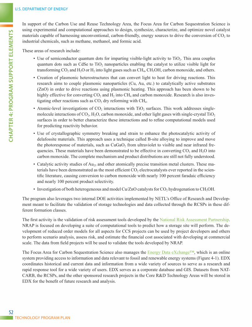
U.S. DEPARTMENT OF ENERGY
TECHNOLOGY PROGRAM PLAN
CHA
PTER
4: P
ROG
RAM
SU
PPO
RT E
LEM
ENTS
52
In support of the Carbon Use and Reuse Technology Area, the Focus Area for Carbon Sequestration Science is using experimental and computational approaches to design, synthesize, characterize, and optimize novel catalyst materials capable of harnessing unconventional, carbon-friendly, energy sources to drive the conversion of CO2 to industrial chemicals, such as methane, methanol, and formic acid.
These areas of research include:
• Use of semiconductor quantum dots for imparting visible-light activity to TiO2. This area couples quantum dots such as CdSe to TiO2 nanoparticles enabling the catalyst to utilize visible light for transforming CO2 and H2O or H2 into light gases such as CH4, CH3OH, carbon monoxide, and others.
• Creation of plasmonic heterostructures that can convert light to heat for driving reactions. This research aims to couple plasmonic nanoparticles (Cu, Au, etc.) to catalytically active substrates (ZnO) in order to drive reactions using plasmonic heating. This approach has been shown to be highly effective for converting CO2 and H2 into CH4 and carbon monoxide. Research is also inves-tigating other reactions such as CO2 dry reforming with CH4.
• Atomic-level investigations of CO2 interactions with TiO2 surfaces. This work addresses single-molecule interactions of CO2, H2O, carbon monoxide, and other light gases with single-crystal TiO2 surfaces in order to better characterize these interactions and to refine computational models used for predicting reactivity behavior.
• Use of crystallographic symmetry breaking and strain to enhance the photocatalytic activity of delafossite materials. This approach uses a technique called B-site alloying to improve and move the photoresponse of materials, such as CuGaO2 from ultraviolet to visible and near infrared fre-quencies. These materials have been demonstrated to be effective in converting CO2 and H2O into carbon monoxide. The complete mechanism and product distributions are still not fully understood.
• Catalytic activity studies of Au25 and other atomically precise transition metal clusters. These ma-terials have been demonstrated as the most efficient CO2 electrocatalysts ever reported in the scien-tific literature, causing conversion to carbon monoxide with nearly 100 percent faradaic efficiency and nearly 100 percent product selectivity.
• Investigation of both heterogeneous and model Cu/ZnO catalysts for CO2 hydrogenation to CH3OH.
The program also leverages two internal DOE activities implemented by NETL’s Office of Research and Develop-ment meant to facilitate the validation of storage technologies and data collected through the RCSPs in these dif-ferent formation classes.
The first activity is the validation of risk assessment tools developed by the National Risk Assessment Partnership. NRAP is focused on developing a suite of computational tools to predict how a storage site will perform. The de-velopment of reduced order models for all aspects for CCS projects can be used by project developers and others to perform scenario analysis, assess risk, and estimate the financial cost associated with developing at commercial scale. The data from field projects will be used to validate the tools developed by NRAP.
The Focus Area for Carbon Sequestration Science also manages the Energy Data eXchange™, which is an online system providing access to information and data relevant to fossil and renewable energy systems (Figure 4-1). EDX coordinates historical and current data and information from a wide variety of sources to serve as a research and rapid response tool for a wide variety of users. EDX serves as a corporate database and GIS. Datasets from NAT-CARB, the RCSPs, and the other sponsored research projects in the Core R&D Technology Areas will be stored in EDX for the benefit of future research and analysis.
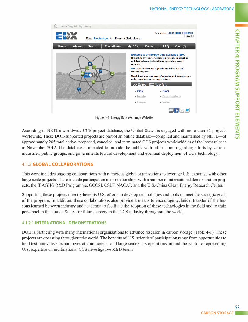
CARBON STORAGE
NATIONAL ENERGY TECHNOLOGY LABORATORYCH
APTER 4: PRO
GRA
M SU
PPORT ELEM
ENTS
53
Figure 4-1. Energy Data eXchange Website
According to NETL’s worldwide CCS project database, the United States is engaged with more than 55 projects worldwide. These DOE-supported projects are part of an online database—compiled and maintained by NETL—of approximately 265 total active, proposed, canceled, and terminated CCS projects worldwide as of the latest release in November 2012. The database is intended to provide the public with information regarding efforts by various industries, public groups, and governments toward development and eventual deployment of CCS technology.
4.1.2 GLOBAL COLLABORATIONS
This work includes ongoing collaborations with numerous global organizations to leverage U.S. expertise with other large-scale projects. These include participation in or relationships with a number of international demonstration proj-ects, the IEAGHG R&D Programme, GCCSI, CSLF, NACAP, and the U.S.-China Clean Energy Research Center.
Supporting these projects directly benefits U.S. efforts to develop technologies and tools to meet the strategic goals of the program. In addition, these collaborations also provide a means to encourage technical transfer of the les-sons learned between industry and academia to facilitate the adoption of these technologies in the field and to train personnel in the United States for future careers in the CCS industry throughout the world.
4.1.2.1 INTERNATIONAL DEMONSTRATIONS
DOE is partnering with many international organizations to advance research in carbon storage (Table 4-1). These projects are operating throughout the world. The benefits of U.S. scientists’ participation range from opportunities to field test innovative technologies at commercial- and large-scale CCS operations around the world to representing U.S. expertise on multinational CCS investigative R&D teams.
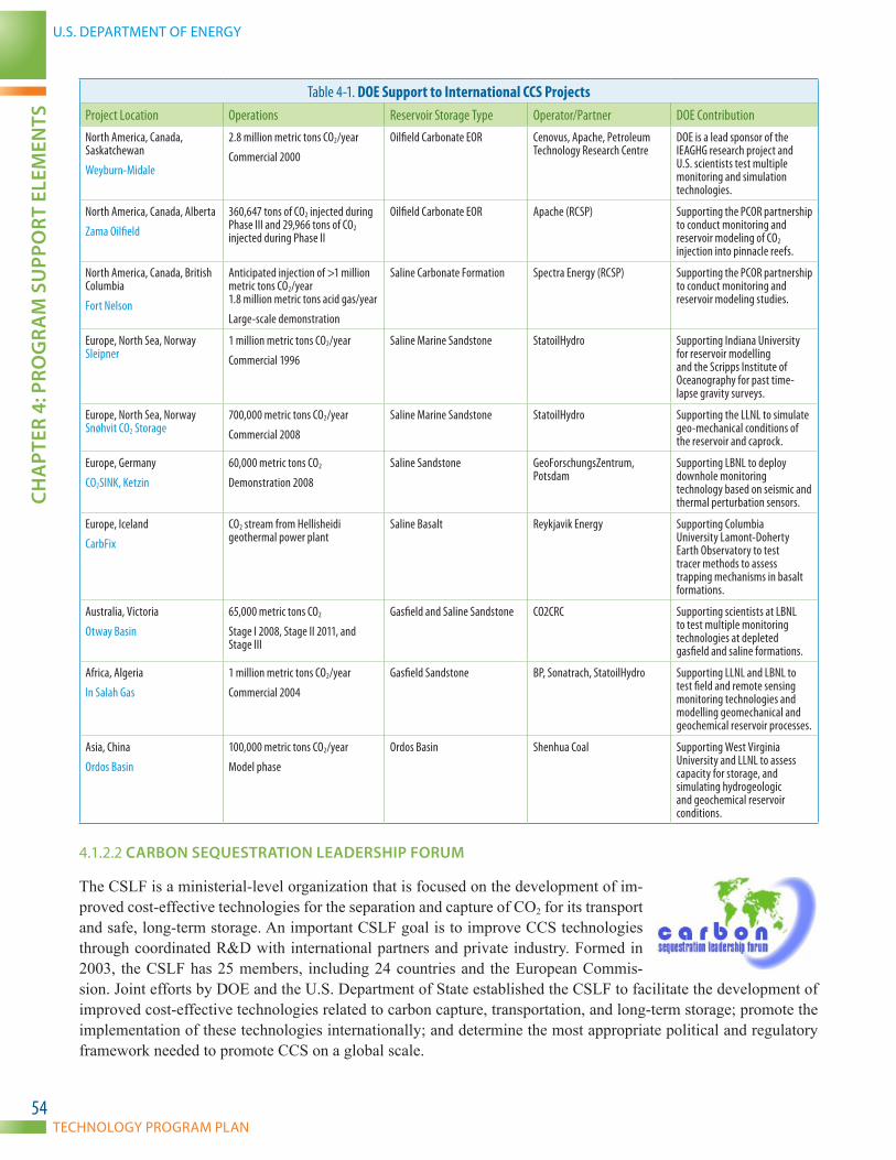
U.S. DEPARTMENT OF ENERGY
TECHNOLOGY PROGRAM PLAN
CHA
PTER
4: P
ROG
RAM
SU
PPO
RT E
LEM
ENTS
54
Table 4-1. DOE Support to International CCS ProjectsProject Location Operations Reservoir Storage Type Operator/Partner DOE ContributionNorth America, Canada, Saskatchewan
Weyburn-Midale
2.8 million metric tons CO2/year
Commercial 2000
Oilfield Carbonate EOR Cenovus, Apache, Petroleum Technology Research Centre
DOE is a lead sponsor of the IEAGHG research project and U.S. scientists test multiple monitoring and simulation technologies.
North America, Canada, Alberta
Zama Oilfield
360,647 tons of CO2 injected during Phase III and 29,966 tons of CO2 injected during Phase II
Oilfield Carbonate EOR Apache (RCSP) Supporting the PCOR partnership to conduct monitoring and reservoir modeling of CO2 injection into pinnacle reefs.
North America, Canada, British Columbia
Fort Nelson
Anticipated injection of >1 million metric tons CO2/year 1.8 million metric tons acid gas/year
Large-scale demonstration
Saline Carbonate Formation Spectra Energy (RCSP) Supporting the PCOR partnership to conduct monitoring and reservoir modeling studies.
Europe, North Sea, Norway Sleipner
1 million metric tons CO2/year
Commercial 1996
Saline Marine Sandstone StatoilHydro Supporting Indiana University for reservoir modelling and the Scripps Institute of Oceanography for past time-lapse gravity surveys.
Europe, North Sea, Norway Snøhvit CO2 Storage
700,000 metric tons CO2/year
Commercial 2008
Saline Marine Sandstone StatoilHydro Supporting the LLNL to simulate geo-mechanical conditions of the reservoir and caprock.
Europe, Germany
CO2SINK, Ketzin
60,000 metric tons CO2
Demonstration 2008
Saline Sandstone GeoForschungsZentrum, Potsdam
Supporting LBNL to deploy downhole monitoring technology based on seismic and thermal perturbation sensors.
Europe, Iceland
CarbFix
CO2 stream from Hellisheidi geothermal power plant
Saline Basalt Reykjavik Energy Supporting Columbia University Lamont-Doherty Earth Observatory to test tracer methods to assess trapping mechanisms in basalt formations.
Australia, Victoria
Otway Basin
65,000 metric tons CO2
Stage I 2008, Stage II 2011, and Stage III
Gasfield and Saline Sandstone CO2CRC Supporting scientists at LBNL to test multiple monitoring technologies at depleted gasfield and saline formations.
Africa, Algeria
In Salah Gas
1 million metric tons CO2/year
Commercial 2004
Gasfield Sandstone BP, Sonatrach, StatoilHydro Supporting LLNL and LBNL to test field and remote sensing monitoring technologies and modelling geomechanical and geochemical reservoir processes.
Asia, China
Ordos Basin
100,000 metric tons CO2/year
Model phase
Ordos Basin Shenhua Coal Supporting West Virginia University and LLNL to assess capacity for storage, and simulating hydrogeologic and geochemical reservoir conditions.
4.1.2.2 CARBON SEQUESTRATION LEADERSHIP fORUM
The CSLF is a ministerial-level organization that is focused on the development of im-proved cost-effective technologies for the separation and capture of CO2 for its transport and safe, long-term storage. An important CSLF goal is to improve CCS technologies through coordinated R&D with international partners and private industry. Formed in 2003, the CSLF has 25 members, including 24 countries and the European Commis-sion. Joint efforts by DOE and the U.S. Department of State established the CSLF to facilitate the development of improved cost-effective technologies related to carbon capture, transportation, and long-term storage; promote the implementation of these technologies internationally; and determine the most appropriate political and regulatory framework needed to promote CCS on a global scale.

CARBON STORAGE
NATIONAL ENERGY TECHNOLOGY LABORATORYCH
APTER 4: PRO
GRA
M SU
PPORT ELEM
ENTS
55
The CSLF held its fourth Ministerial meeting in Beijing, China, on September 19–23, 2011. Energy and Environ-ment Ministers who attended the conference endorsed CCS as one of the low-carbon technology options critical to the global quest to reduce CO2 emissions to the atmosphere. In addition to calling for additional CCS projects on a global scale, the CSLF Ministers:
• Agreed to extend and amend the CSLF charter to include facilitation and deployment of technolo-gies for utilization of captured CO2.
• Welcomed additional international collaborations on CCS through IEA, GCCSI, Clean Energy Ministerial, and multilateral financial institutions.
• Supported strategies for the CSLF to resolve barriers for successful implementation of CCS proj-ects at a time of significant global economic challenge.
• Strongly encouraged continued involvement of stakeholders from industry, academia, and society in the CSLF and its activities.
• Added 6 new CCS projects to its existing R&D portfolio, increasing the total number of recognized projects to 36.
Ministers recognized the success of the CSLF in providing governments with an international forum to collaborate and create shared commitments to CCS RD&D and deployment, including ongoing CSLF initiatives to:
• Share information internationally on important CCS projects.
• Build the capacity for CCS in the developing country CSLF members.
• Explore methods for financing CCS projects, particularly in developing countries.
• Develop global roadmaps for RD&D of CCS technologies.
DOE continues to maintain a leadership role in the CSLF. The next Ministerial meeting is scheduled for November 2013 in Washington, DC.
4.1.2.3 NORTH AMERICAN CARBON ATLAS PARTNERSHIP
NACAP is one of the key efforts of the North American Energy Working Group and is a joint CO2 mapping initiative involving the United States, Canada, and Mexico. The purpose of NACAP is to create a North American carbon storage atlas that will speed the development of a comprehensive GIS database for CO2 stationary sources and geo-logic reservoirs and help build collaboration among the three countries on CCS.
NACAP was launched in 2008 and is made up of four working groups: the Meth-odology Working Group, the Information Technology Working Group, the Policy Working Group, and the Atlas Development and Production Working Group. A hard-copy and virtual atlas, published in April 2012, are available via the NETL website.
4.1.2.4 OTHER INTERNATIONAL ACTIVITIES
In addition to support provided to the international organizations and projects, DOE advances international CCS ef-forts by working closely with the IEAGHG R&D Programme, IEA, and North American partners through trilateral and bilateral agreements on energy with Canada and Mexico.
The IEAGHG R&D Programme is a multilateral organization that promotes energy security, economic develop-ment, and environmental protection throughout the world. The IEAGHG R&D Programme has established net-works to bring together the expertise and experience of organizations at the forefront of RD&D into GHG mitiga-tion technologies.
U.S. DEPARTMENT OF ENERGY
TECHNOLOGY PROGRAM PLAN
CHA
PTER
4: P
ROG
RAM
SU
PPO
RT E
LEM
ENTS
56
These networks include:
• Monitoring Network
• Risk Management Network
• Wellbore Integrity Network
• Joint Network Meeting
• Modeling Network
• Social Research Network
• Environmental Research into CO2 Storage Network
NETL-funded researchers are actively involved in these networks presenting on lessons learned.
IEAGHG R&D Programme experts have endorsed the efforts of DOE’s RCSP Initiative and their large-scale proj-ects as a successful approach to advance CCS in the United States, Canada, and internationally. These endorsements resulted from extensive peer reviews of the program conducted by the IEAGHG R&D Programme in 2008 and 2011.
DOE has directly supported the development of projects through these organizations and has promoted the transfer of technologies from Core R&D and lessons learned from the RCSPs to support global deployment of CCS technol-ogies. DOE/NETL believes that the economic rewards achieved through new business opportunities in the United States and abroad will provide leverage to assist other countries to engage in CO2 storage projects.
4.1.3 ADDITIONAL SUPPORTING ELEMENTS
4.1.3.1 INTERAGENCY AND STATE COORDINATION
The program team has and will continue to collaborate extensively with different Federal and State agencies and especially through the Interagency Task Force to help inform regulatory issues that have not yet been addressed for wide-scale deployment of CCS technologies. This includes interacting with EPA, the U.S. Department of Interior’s BOEM, Bureau of Land Management (BLM) and U.S. Geological Survey (USGS), the Interstate Oil and Gas Compact Commission (IOGCC), Ground Water Protection Council, and the U.S. Department of Transportation on issues related to CO2 storage and transport. The objective of these efforts is to provide results from research that help inform regulatory decision making. The methodologies developed and data collected by the program are also providing support to BLM, BOEM, and USGS as they determine the potential for Federal lands to play a role in developing CCS opportunities both onshore and offshore.
With regard to CO2 storage, activities with these agencies include: participating in EPA’s CCS Working Group, participating in the preparation of several BLM reports to Congress, collaborating with USGS on storage capacity resource assessment, assisting BOEM with developing rules for offshore CO2 injection, examining the legal and regulatory framework for CO2 storage with IOGCC, and examining State regulatory program data management for CO2 storage with the Ground Water Protection Council. The RCSPs and small-scale field injection projects have also interacted extensively with EPA and state regulatory agencies mostly through the permitting process. EPA partici-pates as an expert panelist for the IEAGHG R&D Programme Peer Review. The Carbon Storage program has col-laborated with Department of Transportation, the Federal Energy Regulatory Commission, the National Association of Regulatory Utility Commissioners, and the Surface Transportation Board to examine the regulatory framework for CO2 pipeline siting, operation, and tariffs. The program has also participated in the IOGCC Pipeline Transporta-tion Task Force on CO2 pipelines for carbon storage. All of this involves more than 20 States and Canadian Provinces that are members of IOGCC. All of this work supports the previously cited Interagency Task Force on CCS.

CARBON STORAGE
NATIONAL ENERGY TECHNOLOGY LABORATORYCH
APTER 4: PRO
GRA
M SU
PPORT ELEM
ENTS
57
4.1.3.2 ARRA EffORTS TO PROMOTE INfRASTRUCTURE DEVELOPMENT
Among the challenges for wide-scale deployment of CCS technologies is the need to identify appropriate CO2 stor-age locations throughout the United States, develop a pipeline network system, and have a pool of trained profes-sionals and trades people to build and operate these facilities. Funding from the American Recovery and Reinvest-ment Act of 2009 has helped to address these program challenges through geologic storage site characterization and geologic storage training and research.
The purpose of geologic storage site characterization is to accelerate the comprehensive identification and charac-terization of potential large-volume geologic formations, thus augmenting characterization efforts and refinement of geologic storage resource potential conducted by the RCSPs. Ten projects were awarded in 2009 and activities are currently underway to assess high-priority sites for future commercial interests. The site characterization projects were awarded approximately $100 million to characterize high-priority geologic storage formations that have the potential for future commercial-scale storage projects. These site characterization efforts include drilling stratigraph-ic wells to collect whole and sidewall core data on confining and injection zones, conducting comprehensive logging suites and formation evaluation projects, and analyzing the chemistry of formation rocks and fluids. The character-ization efforts will also include the acquisition of two-dimensional and/or three-dimensional seismic surveys that integrate rock property data acquired from new wellbores with other existing data to validate seismic responses. The integration of these data will provide a better understanding of the subsurface properties that will be necessary to develop dynamic models to account for CO2 migration. All of the information gathered from these projects will be incorporated into NATCARB to improve future CO2 storage resource estimates in the United States. These efforts represent another step toward understanding the geology of potential storage formations in the United States.
The purpose of geologic storage training and research is to develop the next generation of scientists and engineers for CCS by implementing training and research efforts conducted primarily at colleges and universities. Fifty proj-ects were awarded, including 7 CCS training centers and 43 grants to universities to support students pursuing R&D and future careers with CCS. Several courses have been developed by these training centers. As of June 2013, 247 students have participated in these courses. In addition, as of June 2013, the ARRA Regional Carbon Sequestration Training Centers have trained more than 3,612 participants and distributed more than 10,983 continuing education units and professional development hours.
4.1.3.3 SYSTEMS AND BENEfITS ANALYSIS
NETL’s OPPB conducts analyses to demonstrate how R&D activities support national and international priorities related to energy supply, energy use, and environmental protection. See Section 2.2—Carbon Storage Program Benefits for more information.
4.1.3.4 UNIVERSITY AND RESEARCH COLLABORATIONS
NETL has formed the RUA for energy technology innovation in partnership with a consortium of five nationally recognized universities. RUA consists of Carnegie Mellon University, Penn State University, the University of Pittsburgh, Virginia Tech, and West Virginia University. The RUA research program assists NETL in conducting both basic and applied energy and environmental research that support DOE’s mission to advance U.S. national, economic, and energy security goals.
U.S. DEPARTMENT OF ENERGY
TECHNOLOGY PROGRAM PLAN
ABB
REV
IATI
ON
S
58
ABBREVIATIONSARRA American Recovery and Reinvestment ActAu gold
BLM Bureau of Land ManagementBOEM Bureau of Ocean Energy ManagementBPM Best Practice ManualBSCSP Big Sky Carbon Sequestration Partnership
CBM coalbed methaneCCRP Clean Coal Research ProgramCCS carbon capture and storageCdSe cadmium selenideCH3OH methanolCH4 methaneCO2 carbon dioxideCOE cost of electricityCSLF Carbon Sequestration Leadership ForumCTUS CO2 capture, transport, utilization, and storageCu copper
DOE Department of Energy
ECBM enhanced coalbed methaneEDX Energy Data eXchange™EOR enhanced oil recoveryEPA U.S. Environmental Protection Agency
FE Office of Fossil Energy
GCCSI Global Carbon Capture and Storage InstituteGHG greenhouse gasGIS geographic information systemGSRA Geologic Storage Technologies and Simulation and
Risk Assessment
H2 hydrogenH2O waterHNP huff ‘n’ puff
IEA International Energy AgencyIEAGHG IEA’s Greenhouse Gas R&D Programme
IOGCC Interstate Oil and Gas Compact CommissionIPCC United Nations’ Intergovernmental Panel on Climate
Change
LBNL Lawrence Berkeley National LaboratoryLLNL Lawrence Livermore National Laboratory
MGSC Midwest Geological Sequestration ConsortiumMRCSP Midwest Regional Carbon Sequestration PartnershipMVA monitoring, verification, and accounting
NACAP North American Carbon Atlas PartnershipNASA National Aeronautics and Space AdministrationNATCARB National Carbon Sequestration Database and
Geographic Information SystemNEMS National Energy Modeling SystemNETL National Energy Technology LaboratoryNRAP National Risk Assessment Partnership
OPPB Office of Program Performance and Benefits
PCOR Plains CO2 Reduction Partnership
R&D research and developmentRCSP Regional Carbon Sequestration PartnershipRD&D research, development, and demonstrationRUA Regional University Alliance
SECARB Southeast Regional Carbon Sequestration PartnershipSWP Southwest Partnership on Carbon Sequestration
TiO2 titanium dioxideTRL Technology Readiness Level
USGS U.S. Geological Survey
WESTCARB West Coast Regional Carbon Sequestration Partnership
ZnO zinc oxide

CARBON STORAGE
NATIONAL ENERGY TECHNOLOGY LABORATORY
THIS PAGE INTENTIONALLY LEFT BLANK
ABBREV
IATION
S
59

U.S. DEPARTMENT OF ENERGY
TECHNOLOGY PROGRAM PLAN
fOR
MO
RE IN
fORM
ATIO
N
60
FOR MORE INFORMATION
The NETL website offers extensive information about the components of DOE’s Carbon Storage program. The website provides an extensive program overview webpage with details about the Core R&D and Infrastructure com-ponents, systems analyses capabilities, a FAQ information portal, information about the RCSPs with links to their websites, and an extensive reference shelf. Links to numerous resources can be accessed via the Carbon Storage Reference Shelf on the NETL website. Each of the categories on the Carbon Storage Reference Shelf has a variety of documents posted for easy access to current information:
• The Carbon Storage Newsletter
• Major Carbon Storage Educational Resources
• Program Overview Presentations
• Program Reports, Plans, and Roadmaps
• Journals and Scientific Articles
• Conference Proceedings and Presentations
• Project Descriptions
• Program Factsheets
• Regulatory and Policy Issues
• Systems Analyses
• Peer Reviews
• Best Practice Manuals
CARBON STORAGE
NATIONAL ENERGY TECHNOLOGY LABORATORYfO
R MO
RE INfO
RMATIO
N
61
National Energy Technology Laboratoryhttp://www.netl.doe.gov/sequestration
U.S. Department of Energy, Office of Fossil Energyhttp://www.doe.gov/sciencetech/carbonsequestration.htm
If you have any questions, comments, or would like more information about the DOE/NETL Carbon Storage
program, please contact the following persons:
National Energy Technology Laboratory
Traci RodostaCarbon Storage Program Technology [email protected]
Kanwal MahajanCarbon Storage Program Division [email protected]
Bruce BrownCarbon Storage Program RCSP [email protected]
Bill AljoeCarbon Storage Program Core R&D [email protected]
Karen KlugerCarbon Storage Program International [email protected]
U.S. Department of Energy
Mark [email protected]
William [email protected]
Jeff [email protected]
National Energy Technology Laboratory (NETL) U.S. Department of Energy
Albany Location: 1450 Queen Avenue SW Albany, OR 97321-2198 541.967.5892
Anchorage Location: 420 L Street Suite 305 Anchorage, AK 99501 907.271.3618
Morgantown Location: 3610 Collins Ferry Road P.O. Box 880 Morgantown, WV 26507-0880 304.285.4764
Pittsburgh Location: 626 Cochrans Mill Road Pittsburgh, PA 15236-0940 412.386.4687
Sugar Land Location: 13131 Dairy Ashford Road Suite 225 Sugar Land, TX 77478 281.494.2516
Customer Service 1.800.553.7681
Website www.netl.doe.gov
TECHNOLOGY PROGRAM PLANSEPTEMBER 2013
CARBON STORAGE