carbon nanomaterials for high-performance supercapacitors articles... · supercapacitors due to...
TRANSCRIPT

Materials Today � Volume 16, Numbers 7/8 � July/August 2013 RESEARCH
Carbon nanomaterials for high-performance supercapacitors
RESEARCH:Review
Tao Chen and Liming Dai*
Center of Advanced Science and Engineering for Carbon (Case4Carbon), Department of Macromolecular Science and Engineering, Case Western Reserve
University, 10900 Euclid Avenue, Cleveland, OH 44106, USA
Owing to their high energy density and power density, supercapacitors exhibit great potential as high-
performance energy sources for advanced technologies. Recently, carbon nanomaterials (especially,
carbon nanotubes and graphene) have been widely investigated as effective electrodes in
supercapacitors due to their high specific surface area, excellent electrical and mechanical properties.
This article summarizes the recent progresses on the development of high-performance supercapacitors
based on carbon nanomaterials and provides various rational concepts for materials engineering to
improve the device performance for a large variety of potential applications, ranging from consumer
electronics through wearable optoelectronics to hybrid electric vehicles.
IntroductionGlobal energy consumption, along with CO2 emission, has been
accelerating at an alarming rate due to rapid global economic
expansion, an increase in the world population, and an ever-
increasing human reliance on energy-consuming appliances. It
has been estimated that the world will need to double its energy
supply by 2050 (see the World Energy Council Website at
www.worldenergy.org). The rapid increase in global energy con-
sumption and the environmental impact of traditional energy
resources pose serious challenges to human health, energy secur-
ity, and the environment; and reveal a growing need to develop
new types of clean and sustainable energy conversion and storage
systems, such as batteries and supercapacitors for electric vehicles
with low exhaust emissions.
Supercapacitors, also called as ultracapacitors, are electrochemi-
cal energy storage devices that combine the high energy-storage-
capability of conventional batteries with the high power-delivery-
capability of conventional capacitors [1–4]. Being able to achieve
higher power and longer cycle life than conventional dielectric
capacitors and batteries, supercapacitors have been developed to
providepower pulses for a largevarietyofapplications, ranging from
consumer electronics through hybrid electric vehicles (HEVs) to
industrial electric utilities [5]. Therefore, supercapacitors play
an important role in achieving better fuel economy, decreasing
*Corresponding author:. Dai, L. ([email protected])
272 1369-7021/06/$ - see front matter � 2013 E
harmful emissions, and reducing the reliance on petroleum sources.
The world market for supercapacitors has been growing steadily and
rapidly [1]. To improve the performance of state-of-the-art super-
capacitors to meet the stringent requirements for the applications
mentioned above, and many other advanced applications not dis-
cussed (e.g. portable, transparent and wearable electronics), new
electrode materials with superior properties over those of current
activated carbon electrodes are needed and new device structures
(e.g. all-solid state supercapacitors [6,7], optically transparent [8,9],
mechanically flexible and stretchable [10–12], and even fiber-
shaped [13–15] supercapacitors) are highly desirable.
Nanotechnology has opened up new frontiers by offering
unique enabling technologies and new materials for energy sto-
rage. In particular, graphitic carbon nanomaterials (e.g. carbon
nanotubes, graphene sheets) have been playing a more and more
important role in the development of high-performance super-
capacitors [4,5]. The aim of this article is to summarize recent
progress in the development of supercapacitors (especially elec-
trical double layer capacitors) based on carbon nanomaterials and
to provide various rational concepts for materials engineering to
improve device performance.
SupercapacitorsA typical supercapacitor consists of three essential components,
namely the electrodes, the electrolyte, and the separator. The
overall performance of supercapacitors is determined by the
lsevier Ltd. All rights reserved. http://dx.doi.org/10.1016/j.mattod.2013.07.002

Materials Today � Volume 16, Numbers 7/8 � July/August 2013 RESEARCH
RESEARCH:Review
physical properties of both the electrode and the electrolyte
materials. Nevertheless, the electrode is one of the most important
components for charge storage/delivery, and plays a crucial role in
determining the energy and power densities of a supercapacitor.
The electrochemical performance of a supercapaictor can be char-
acterized by cyclic voltammetry and galvanostatic charge–dis-
charge measurements [1–4]. The capacitance (C) is determined
from the constant current discharge curves according to Eqn 1:
C ¼ I
ðdV=dtÞ (1)
where I is the discharge current and dV/dt is calculated from the
slope of the discharge curve. Then, the specific capacitance (CSP)
for one electrode in a supercapacitor can be calculated using the
following equation:
CSP ðF g�1Þ ¼ 4C
m(2)
where C is the measured capacitance for the two-electrode cell and
m is the total mass of the active materials in both electrodes. The
mass can also be replaced by volume or area of the electrodes
depending on the nature of the targeted applications. The stored
energy (E) and the power density (P) in a supercapacitor can then
be calculated from Eqns 3 and 4, respectively:
E ¼ ðCV2Þ2
(3)
P ¼ V2
ð4RsÞ(4)
where C (F g�1) is the total capacitance of the cell, V is the cell
voltage, and RS is the equivalent series resistance.
The principle of energy storage in a supercapacitor can be either
(i) electrostatic charge accumulation at the electrode/electrolyte
interface (electrical double layer capacitance, EDLC), as schema-
tically shown in Fig. 1, or (ii) charge transfer, via reversible (Far-
adaic) redox reaction(s), to redox materials (e.g. conductive
polymers, metal oxide nanoparticles) on the surface of electrode
(pseudo-capacitance). In practical supercapacitors, the two storage
mechanisms often work simultaneously [16]. Different charge
transfer processes involved in the EDLC and pseudo-capacitance
[4,5,16]. In EDLC, the energy is stored through ion adsorption[(Figure_1)TD$FIG]
FIGURE 1
Schematic illustration of the charging/discharging process in a supercapacitor.
(a purely electrostatic process) at the electrode-electrolyte inter-
face with no charge transfer across the electrodes, suggesting a
non-faradic process. By contrast, pseudo-capacitance arises from
reversible redox reaction(s) between the electrolyte and active
species on the surface of electrodes. Although pseudo-capacitance
higher than EDLC capacitance can be achieved, supercapacitors
based on pseudo-capacitance often suffer from the poor electrical
conductivity of the electroactive species, and hence demonstrate
low power density and cycling stability. Therefore, the combina-
tion of both EDLC and pseudo-capacitance presents an effective
means to improve the overall capacitance of a supercapacitor.
Since both EDLC and pseudocapacitance are surface phenom-
ena, high-surface-area mesoporous carbon and activated carbons
(specific surface area: 1000–2000 m2 g�1) have been widely used as
electrode materials in both academic and commercial supercapa-
citors [16–19]. Taking a specific surface area of 1000 m2 g�1 for
carbon as an example, its ideal attainable capacitance could be
200–500 F g�1. However, the practically obtained values are of
only a few tens of F g�1. Activated carbons have a wide pore size
distribution, consisting of micropores (<2 nm), mesopores (2–
50 nm), and macropores (>50 nm) [17,18], with most of the sur-
face area of activated carbons being on the scale of micropores [20].
Pores of this size are often poorly or non-accessible for electrolyte
ions (especially for organic electrolytes), and thus are incapable of
supporting an electrical double layer. By contrast, mesopores
contribute the most to the capacitance in an electrical double-
layer capacitor [21–23]. However, recent experimental and theo-
retical studies have demonstrated that charge storage in pores 0.5–
2 nm in size (smaller than the size of solvated electrolyte ions)
increased with decreasing pore size due to the closer approach of
the ion center to the electrode surface in the smaller pores [18,24–
26]. Pores less than 0.5 nm wide are too small for double layer
formation [26]. Currently available activated carbon materials
have a high surface area but unfortunately a low mesoporosity,
and hence a limited capacitance due to a low electrolyte accessi-
bility [20]. This translates to the limited energy density of the
resultant supercapacitors (Eqn 3). The low electrolyte accessibility
of activated carbons, coupled with their poor electrical conduc-
tivity, produces a high internal resistance and hence a low power
density for the capacitors (Eqn 4) [20]. Consequently, a limited
energy density (4–5 Wh kg�1) and a limited power density
273

RESEARCH Materials Today � Volume 16, Numbers 7/8 � July/August 2013
RESEARCH:Review
(1–2 kW kg�1) have been obtained for currently available super-
capacitors based on the activated carbon electrodes [20]. Clearly,
therefore, new materials are needed to overcome the drawbacks of
activated carbon electrode materials to improve the performances
for supercapacitors.
Owing to their large surface area, high mesoporosity and elec-
trolyte accessibility, and good electrical properties, carbon nano-
materials, especially graphene and carbon nanotubes (CNTs), are
very promising candidates to replace activated carbons as the
electrode materials in high-performance supercapacitors [27,28].
Graphene, a single-atom-thick layer of sp2 carbon atoms densely
packed into a two-dimensional (2D) honeycomb lattice, can be
viewed as the basic building block for carbon materials of all other
dimensionalities, such as 0D fullerene, 1D nanotubes, and 3D
graphite (Fig. 2) [27]. For instance, a carbon nanotube (CNT)
may be conceptually viewed as a graphene sheet that is rolled
into a nanoscale tube form as a single-walled carbon nanotube
(SWNT), or as a multiwalled carbon nanotube (MWNT) with
additional graphene coaxial tubes around the SWNT core [29].
CNTs with a high aspect ratio, large specific surface area (SWNT
>1600 m2 g�1, MWNT >430 m2 g�1) [30,31] as well as good
mechanical and electrical (�5000 S cm�1) properties have been
widely used as the active electrodes in supercapacitors [28,32–37].
Having many similarities to CNTs in structure and properties,[(Figure_2)TD$FIG]
FIGURE 2
The mother of all graphitic forms. Graphene is a 2D building block for carbon m
buckyballs, rolled into 1D nanotubes or stacked into 3D graphite [27]. Reprinted
274
including its high aspect ratio (the ratio of lateral size to thickness),
large surface (2630 m2 g�1) [38–40], excellent carrier mobility
(15,000 cm2 V�1 s�1 for both electrons and holes) [41], and good
mechanical properties [42], graphene is an attractive candidate for
many potential applications where CNTs have been exploited.
Superior to CNTs, one-atom-thick graphene sheets with a 2D
planar geometry could offer additional advantages as more effec-
tive electrode materials in supercapacitors [43]. Furthermore, the
availability of many rational strategies for materials engineering
and rich chemistries for controlled functionalization of both CNTs
and graphene should facilitate materials engineering for the devel-
opment of various high-performance supercapacitors based on
carbon nanomaterials, as described below.
High-performance supercapacitors by controlling theorientation and tip structure of carbon nanotubesAs mentioned above, CNTs with a high aspect ratio, large specific
surface area [30,31] and high electrical conductivity have been
widely used as the active electrode in supercapacitors [28,32–37].
For instance, a supercapacitor of a specific capacitance of 102 F g�1
with a power density >8 kW kg�1 and an energy density of
�1 Wh kg�1 has been fabricated from electrodes based on free-
standing mats of entangled MWNTs in H2SO4 electrolyte [31].
More recently, a higher specific capacitance of 180 F g�1 has been
aterials of all other dimensionalities. It can be wrapped up into 0D
from Ref. [27] with permission. Copyright 2007, Nature Publishing Group.

Materials Today � Volume 16, Numbers 7/8 � July/August 2013 RESEARCH
RESEARCH:Review
achieved when a random SWNT network (Fig. 3a) was used as the
electrode in a KOH electrolyte [32]. In this particular case, the
maximum power density and energy density approached
20 kW kg�1 and 10 Wh kg�1, respectively. This value of power
density is higher than those attainable by activated carbon-based
commercial capacitors, but the energy density still needs to be
improved. The randomly entangled or bundled structure could
have significantly reduced the CNT specific area with a concomi-
tant decrease in the electrochemical energy-storage performance
[35,44,45].
Compared to their randomly entangled counterparts, vertically-
aligned CNT arrays (VA-CNTs) have been demonstrated to be
advantageous for supercapacitor applications. Unlike the irregular
pore structures of random CNTs (Fig. 3a), the vertically-aligned
structure and the well-defined tube-spacing in a VA-CNT array
(Fig. 3b,c) can provide a more electrolyte-accessible surface. The
aligned structures should also provide improved charge storage/
delivery properties as each of the constituent aligned tubes can be
[(Figure_3)TD$FIG]
FIGURE 3
Typical structures of random, VA-CNTs and the schematic illumination of VA-CNT
SWNTs [32]. Reprinted from Ref. [32] with permission. Copyright 2001, John Wileysolidified with a droplet of liquid (c) [35]. Reprinted from Ref. [35] with permissio
etched VA-CNT electrode (scale bar: 100 mm). (e) Higher magnification view of th
(g) plasma etching (scale bar: 20 nm) (h) Schematic of an electrochemical capaci
[44]. Reprinted from Ref. [44] with permission. Copyright 2009, Elsevier.
connected directly onto a common electrode to allow them to
effectively participate in the charging/discharging process
(Fig. 3d). Moreover, the top end-caps of the VA-CNTs can be
properly opened (e.g. by plasma etching [44,46]) (Fig. 3e–g) to
allow the electrolyte access to the otherwise inaccessible inner
cavity of the VA-CNTs for charge storage. Indeed, recent research
has demonstrated the improved rate capability of VA-CNTs over
randomly entangled CNTs [35,44–49], along with enhanced
energy density (148 Wh kg�1) and power density (315 kW kg�1)
[50–55]. Specifically, a high capacitance has been obtained in 1 M
H2SO4 for a VA-CNT array electrode (365 F g�1) prepared by tem-
plate-assisted CVD [56] and in ionic liquid electrolytes [57] for an
VA-CNT electrode (440 F g�1) prepared by a template-free CVD
approach (Fig. 3e–h) [44,49]. To further optimize the performance
of VA-CNT supercapacitors, conductive polymer (e.g. polyaniline
[58] and polypyrrole [59]) and metal oxide (e.g. MnO2 [60], TiO2
[61] and RuO2 [62]) can be deposited onto the surface of CNTs to
introduce pseudocapacitance.
based supercapacitors. (a) SEM image of the as -grown randomly entangled
and Sons. (b,c) SEM images of the as-grown forest (b) after having beenn. Copyright 2006, Nature Publishing Group. (d) SEM image of a plasma-
e electrode (scale bar: 100 nm). TEM images of the CNTs before (f ) and after
tor based on plasma-etched VA-CNT electrodes and ionic liquid electrolyte.
275

RESEARCH Materials Today � Volume 16, Numbers 7/8 � July/August 2013
RESEARCH:Review
High-performance supercapacitors by controlling theedge-structure and p–p stacking of graphene sheetsSupercapacitors based on CNT electrodes do not exhibit the
expected performance (e.g. specific capacitance below 500 F g�1)
due to the high contact resistance between the CNT electrode and
current collector and its inefficient interaction with the electrolyte.
Besides, it is difficult, if not impossible, to scale up the production of
VA-CNTs for the commercialization of supercapacitors [63]. The
recent availability of solution-processable graphene oxide (GO) by
exfoliation of graphite powder via solution oxidation [64] and edge-
functionalized graphene (EFG) sheets via ball milling [65,66] has
allowed for the large-scale production of graphene materials at a
relatively low cost for various device applications through solution
processing [67]. Due to its large surface area, high carrier transport
mobility and excellent thermal/mechanical stability, graphene has
recently been studied as an alternative carbon based electrode in
supercapacitors [68]. Theoretically, the double-layer capacitance
value of a graphene electrode can reach up to 550 F g�1, the highest
value of intrinsic capacitance among all carbon-based electrodes
[69,70]. Using chemically reduced graphene oxide electrodes, a
supercapacitor with specific capacitances of 135 and 99 F g�1 in
aqueous and organic electrolytes, respectively, has been fabricated
[39], as was a supercapacitor with ultrahigh specific energy
density (85.6 Wh kg�1 at room temperature and 136 Wh kg�1 at
80 8C) [70]. Recently, supercapacitors with high specific capacitance
(276 F g�1), power density (20 W cm�3, 20 times higher than that of
the activatedcarboncounterpart), energydensity (1.36 mWh cm�3,
[(Figure_4)TD$FIG]FIGURE 4
Structure and electrochemical properties of an all-solid-state supercapacitor basefunctionalized graphene. (a) Schematic diagram of the supercapacitor based on L
comparison between performances of LSG-EC using gelled versus aqueous electr
measurements were collected at a scan rate of 1000 mV s�1 [71]. Reprinted from
proposed structures of edge-carboxylated graphene (ECG) and heat-treated (decaCopyright 2012, the National Academy of Sciences.
276
2 times higher than that of the activated carbon counterpart),
and excellent stability during bending from 08 to 1808 have also
been developed by using a standard LightScribe DVD optical drive
to directly reduce graphene oxide films to graphene electrodes
(Fig. 4a–c) [71]. The performance can be further enhanced by using
a conductive polymer [72,73] or metal oxide [74,75] coating to
introduce pseudocapacitance.
Recent work on the EFG with various edge groups (e.g. –H, –
COOH and –SO3H) by effective and eco-friendly ball milling of
graphite (Fig. 4d) provides an effective means for the development
of functionalized graphene materials with tailor-made chemical
structures and electronic properties attractive for multifunctional
applications [65], including large-area transparent and conducting
electrodes for electronics and metal-free catalysts for oxygen
reduction reaction in fuel cells [66]. Although EFGs have hardly
been exploited for energy-storage application, the use of EFGs,
having abundant active sites at the edge and perfect conjugation
(conductivity) on its basal plane, as the electrode materials could
lead to high-performance supercapacitors with a high rate cap-
ability. Through controllable self-assembling, EFGs should also
facilitate the formation of hierarchically structured electrodes in
supercapacitors for specific applications.
High-performance supercapacitors based on 3Dpillared graphene-carbon nanotube networksAlthough graphene sheets with a large surface area are ideal
electrode materials for energy storage, a large portion of the surface
d on laser-scribed graphene (LSG) and the synthetic route to edge-SG. Inset is a photograph showing the flexibility of the device. (b) A
olytes. (c) Flexibility of the LSG-based supercapacitor: current–voltage
Ref. [71] with permission. Copyright 2012, AAAS. (d) Syntheses and
rboxylated) ECG (H-ECG) [65]. Reprinted from Ref. [65] with permission.
Materials Today � Volume 16, Numbers 7/8 � July/August 2013 RESEARCH
RCH:Review
area associated with individual graphene sheets in the graphene
electrode is inaccessible due to restacking via the strong p–p
interaction. Therefore, it is crucial to physically separate 2D gra-
phene sheets to preserve their high surface area, for example by
template-assisted construction of 3D graphene foams (Fig. 5a,b)
with a porous structure and large surface area [76–79]. In addition,
a solution layer-by-layer self-assembling approach to prepare mul-
tilayered hybrid carbon films of alternating poly(ethyleneimine)-
modified graphene sheets and acid-oxidized MWNT layers was
developed to construct supercapacitors with a relatively high
specific capacitance of 120 F g�1 (higher than those of verti-
cally-aligned [35] and random CNT electrodes [32]) and rate cap-
ability since the well-defined interlayers of CNT networks allowed
[(Figure_5)TD$FIG]FIGURE 5
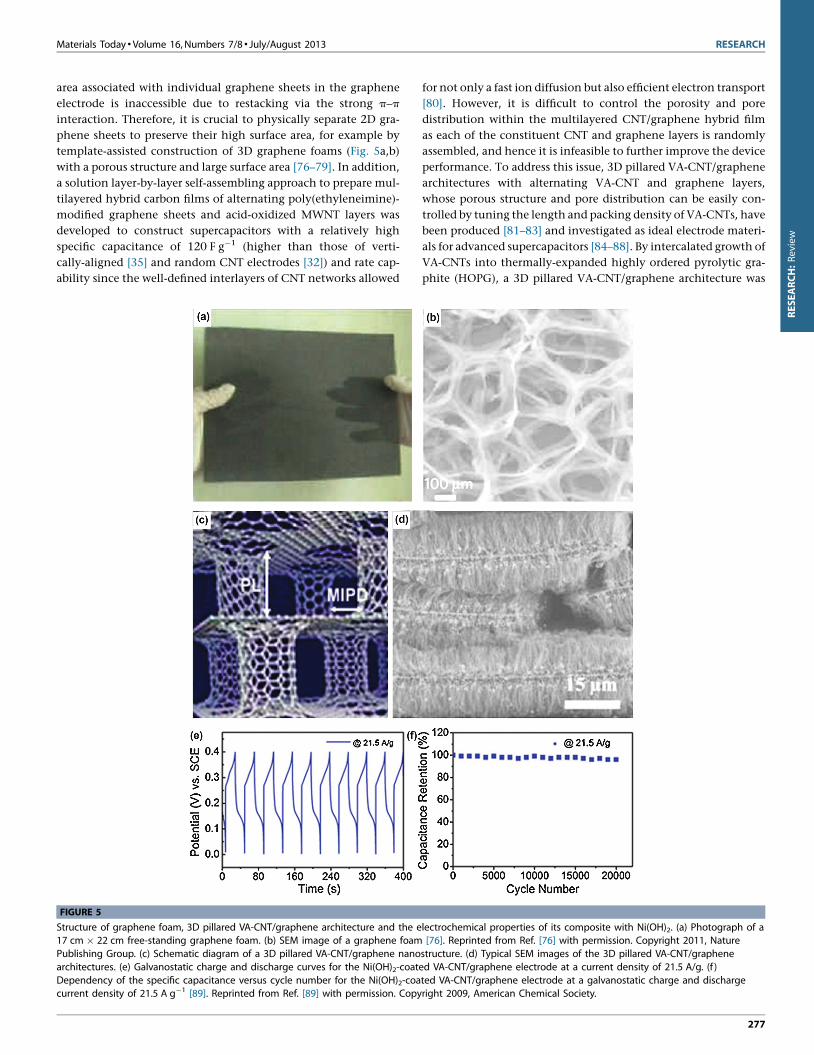
Structure of graphene foam, 3D pillared VA-CNT/graphene architecture and the e17 cm � 22 cm free-standing graphene foam. (b) SEM image of a graphene foam
Publishing Group. (c) Schematic diagram of a 3D pillared VA-CNT/graphene nano
architectures. (e) Galvanostatic charge and discharge curves for the Ni(OH)2-coate
Dependency of the specific capacitance versus cycle number for the Ni(OH)2-coacurrent density of 21.5 A g�1 [89]. Reprinted from Ref. [89] with permission. Copy
for not only a fast ion diffusion but also efficient electron transport
[80]. However, it is difficult to control the porosity and pore
distribution within the multilayered CNT/graphene hybrid film
as each of the constituent CNT and graphene layers is randomly
assembled, and hence it is infeasible to further improve the device
performance. To address this issue, 3D pillared VA-CNT/graphene
architectures with alternating VA-CNT and graphene layers,
whose porous structure and pore distribution can be easily con-
trolled by tuning the length and packing density of VA-CNTs, have
been produced [81–83] and investigated as ideal electrode materi-
als for advanced supercapacitors [84–88]. By intercalated growth of
VA-CNTs into thermally-expanded highly ordered pyrolytic gra-
phite (HOPG), a 3D pillared VA-CNT/graphene architecture was
lectrochemical properties of its composite with Ni(OH)2. (a) Photograph of a[76]. Reprinted from Ref. [76] with permission. Copyright 2011, Nature
structure. (d) Typical SEM images of the 3D pillared VA-CNT/graphene
d VA-CNT/graphene electrode at a current density of 21.5 A/g. (f )
ted VA-CNT/graphene electrode at a galvanostatic charge and dischargeright 2009, American Chemical Society.
277
RESEA

RESEARCH Materials Today � Volume 16, Numbers 7/8 � July/August 2013
RESEARCH:Review
created (Fig. 5c,d) [89], which showed a specific capacitance of
about 110 F g�1 in an electrical double layer supercapacitor. The
resulting 3D pillared structure hybridized with nickel hydroxide
coating showed a high specific capacitance (1065 F g�1, Fig. 5e)
with a remarkable rate capability and excellent long-term electro-
chemical stability – only 4% capacity loss after 20,000 charge–
discharge cycles (Fig. 5f) [89].
The value of 1065 F g�1 is about 10 times that of the high-
surface-area activated carbons (<100 F g�1) [90] and within the
range of 953–1335 F g�1 for graphene-supported single-crystalline
nickel hydroxide hexagonal nanoplates [91]. In the 3D hierarch-
ical structure, VA-CNTs can act as not only mechanical supports
for the graphene layers but also good conductive paths for elec-
trons and ions, and hence the high capacitance and excellent rate
capability.
[(Figure_6)TD$FIG]
FIGURE 6
Supercapacitors with novel structures and their electrochemical performances: (amacrofilm on an elastomeric PDMS substrate for stretchable supercapacitor. (b) C
rates of 100 mV s�1. (c) Long charge–discharge cycling at a constant current den
under 0 and 30% applied tensile strain [10]. Reprinted from Ref. [10] with permis
demonstrating transparent (d) and flexible (e) natures of the supercapacitors [8].Group. (f ) Schematically illustration of a fiber-based supercapacitor. (g) Low-resol
A close-up view (scale bar: 10 mm). (h) Higher-magnification SEM image of the p
permission. Copyright 2012, John Wiley and Sons.
278
High-performance supercapacitors with novelstructuresAs discussed above, significant progress has been achieved with
conventional supercapacitors based on liquid electrolytes. How-
ever, they cannot satisfy the requirements for certain specific
applications, including portable, transparent and wearable elec-
tronics. In this regard, recent work on the development of light-
weight, flexible, stretchable (Fig. 6a–c) [10–12] and/or transparent
(Fig. 6d,e) [8,9] supercapacitors with novel structures (e.g. all-solid
[6,7], fiber-shaped [13–15]; Fig. 6f–h) has attracted a great deal of
attention. Highly-stretchable supercapacitors based on buckled
SWNT macrofilm electrodes have also been developed by coating
a thin SWNT film onto a pre-strained elastomeric substrate (poly-
dimethylsiloxane, PDMS) and followed by relaxation of the pre-
strained substrate (Fig. 6a) [11]. Even when these supercapacitors
) Schematical illustration of the fabrication steps of a buckled SWNTyclic voltammograms of the stretchable supercapacitors measured at scan
sity of 1 A g�1 demonstrates the stability of the stretchable supercapacitor
sion. Copyright 2009, John Wiley and Sons. (d,e) Optical pictures
Reprinted from Ref. [8] with permission. Copyright 2012, Nature Publishingution SEM image of a Kevlar fiber covered with ZnO nanowire arrays. (Inset)
lastic wire, showing arrays of NWs [13]. Reprinted from Ref. [13] with

Materials Today � Volume 16, Numbers 7/8 � July/August 2013 RESEARCH
[(Figure_7)TD$FIG]
FIGURE 7
Structures and properties of integrated self-powering devices in planar and fiber forms. (a,b) Schematic and circuit illustrations of a PSC during the charging
(a) and discharging (b) process. (c,d) The voltage and current profiles versus time for the charging (c) and discharging (d) process of a PSC [95]. Reprinted
from Ref. [95] with permission. Copyright 2011, The Royal Society of Chemistry. (e) Photograph of a typical integrated wire-shaped device consisting of
photoelectric conversion (PC) and energy storage (ES). (f ) SEM image of the end PC part. (g) SEM image of the end ES part. (h) A typical photocharging–discharging curve of the integrated energy wire. The discharging current is 0.1 mA [98]. Reprinted from Ref. [98] with permission. Copyright 2012, John Wiley
and Sons.
RESEARCH:Review
were stretched up to 30% stains, their electrochemical properties
and stabilities remained almost unchanged with respect to the
pristine state (Fig. 6b,c). By extension, stretchable electrodes based
on graphene or aligned CNT films should be potential candidates
for stretchable supercapacitors with a high efficiency [92,93],
which can be used as the energy source for stretchable electronics.
On the other hand, supercapacitors with high optical transparency
(Fig. 6d,e) are useful for personal electronics and energy windows
as power sources; they are also crucial components for many other
power-integrated devices (e.g. self-powered light-emitting diodes,
vide infra). Recently, supercapacitors in a fiber form (Fig. 6f–h)
have been demonstrated to show many unique advantages,
including being lightweight, wearable and flexible, for use as
power sources by integrating them into clothing, bags and other
textiles [13–15]. Specific capacitance as high as 38 mF cm�2 has
been achieved for a fiber-shaped supercapacitor based on the CNT/
PANI composite fiber electrodes [15].
Integrated self-powering systemsSelf-powering systems with integrated energy conversion (e.g.
solar cells) and storage (e.g. supercapacitors) devices have recently
attracted more and more attention [94–96]. Using an SWNT net-
work as the integration platform (Fig. 7a,b), for instance, a prin-
table all-solid integrated device consisting of a polymer solar cell
(PSC) and a supercapacitor has been developed [95]. The super-
capacitor charged when the integrated device was under an illu-
mination of 100 mW cm�1, whereas discharging took place once
the light source was switched off and the device was connected to a
resistor as a load (Fig. 7a,b). Fig. 7c,d shows the voltage and current
profiles versus time of the integrated system during the charging
and discharging process, respectively, with a capacitance of
28 F g�1 [95]. Integrated devices containing an energy conversion
unit and a supercapacitor in a single wire have also been devised
for wearable electronics [97,98]. Specifically, Fig. 7e–g shows an
integrated self-powering energy wire, consisting of a wire-shaped
dye-sensitized solar cell (DSSC) and a supercapacitor both based on
an aligned CNT fiber and modified titanium wire as the two
electrodes, for simultaneous energy conversion and storage [98].
The supercapacitor in this integrated device can be rapidly charged
to a voltage (Fig. 7h) close to the open-circuit voltage of the DSSC
upon light irradiation. The entire energy conversion and storage
efficiency up to 1.5% was obtained by multiplying the energy
conversion efficiency of the solar cell part and the energy storage
efficiency of the storage part. We anticipate considerable technical
challenges ahead but also believe many more developments will be
made over the next few years to advance the fiber-shaped inte-
grated self-powering systems for wearable electronic applications.
Concluding remarksWith global energy consumption and CO2 emissions increasing
exponentially, it is crucial to develop clean and renewable energy
systems and advanced energy storage devices. Nanotechnology
has opened up new frontiers in materials science and engineering
to meet this challenge by creating new materials and technologies
for efficient energy conversion and storage. Of particular interest,
carbon nanomaterials (e.g. CNTs and graphene) have been shown
to be attractive for advanced energy storage applications. Recent
research and development clearly indicate that high-performance
supercapacitors can be prepared by using electrodes based on
vertically-aligned CNTs with opened tips, graphene sheets with
tunable through-thickness p–p stacking interactions and/or edge
functionalities, and 3D pillared graphene-carbon nanotube net-
works. Their performance can be further enhanced by coating with
conductive polymers and/or metal oxide to introduce pseudoca-
pacitance. However, it is still challenging to further improve the
performance of supercapacitors based on carbon nanomaterials.
On one hand, the aggregation of CNTs and/or graphene materials
tends to result in a loss of surface area, and hence inferior device
performance. Carbon nanomaterials with various 3D architectures
(such as CNT arrays, graphene foams, and 3D pillared VA-CNT/
graphene networks), along with the 2D graphene sheet transferred
onto a crumpled structure [99,100], have been developed to
279

RESEARCH Materials Today � Volume 16, Numbers 7/8 � July/August 2013
RESEARCH:Review
prevent the aggregation. On the other hand, the relatively high
cost compared to commercial mesoporous and/or activated car-
bon is another challenge for carbon nanomaterials to be scaled up
for practical application in supercapacitors. Therefore, it is highly
desirable to develop carbon nanomaterials with high charge capa-
city at a low cost (e.g. by ball milling).
For potential applications in portable and wearable optoelec-
tronics, conventional supercapacitors are too heavy and bulky. To
address these challenges, a few optically transparent, mechanically
stretchable, and/or wearable wire-shaped supercapacitors have
been developed based on limited electrode materials. The wire-
shaped supercapacitors and the integrated self-powering systems
play important roles in the development of flexible wearable
optoelectronics. Aligned CNTs and/or graphene films with high
transparency, stretchability, and charge mobility are promising
electrodes for transparent, flexible, and/or stretchable supercapa-
citors, although it is still in the initial research stage. Continued
research efforts in this embryonic field could give birth to a
flourishing area of supercapacitor technologies.
AcknowledgementThe authors are grateful for financial support from AFOSR
(FA9550-12-1-0037, FA-9550-12-1-0069 NSFC-NSF (DMR-
1106160)).
References
1 M. Winter, R.J. Brodd, Chem. Rev. 104 (2004) 4245.
2 P. Simon, Y. Gogotsi, Nat. Mater. 7 (2008) 845.
3 M.D. Stoller, R.S. Ruoff, Energy Environ. Sci. 3 (2010) 1294.
4 L.L. Zhang, X. Zhao, Chem. Soc. Rev. 38 (2009) 2520.
5 W. Lu, L. Dai, in: J.M. Marulanda (Ed.), Carbon Nanotubes, In-Tech, 2010, pp. 563–
589.
6 C. Meng, et al. Nano Lett. 10 (2010) 4025.
7 L. Yuan, et al. ACS Nano 6 (2012) 656.
8 H.Y. Jung, et al. Sci. Rep. 2 (2012) 773.
9 Z. Niu, et al. Small 9 (2013) 518.
10 C. Yu, et al. Adv. Mater. 21 (2009) 4793.
11 X. Li, et al. Nano Lett. 12 (2012) 6366.
12 Z. Niu, et al. Adv. Mater. 25 (7) (2013) 1058.
13 J. Bae, et al. Angew. Chem. Int. Ed. 50 (2011) 1683.
14 Z. Cai, et al. J. Mater. Chem. A 1 (2013) 258.
15 K. Wang, et al. Adv. Mater. 25 (2013) 1494.
16 L.L. Zhang, et al. J. Mater. Chem. 20 (2010) 5983.
17 K. Kierzek, et al. Electrochim. Acta 49 (2004) 515.
18 E. Raymundo-Pinero, et al. Carbon 44 (2006) 2498.
19 E. Raymundo-Pinero, et al. Adv. Mater. 18 (2006) 1877.
20 E. Frackowiak, F. Beguin, Carbon 39 (2001) 937.
21 B. Kastening, S. Spinzig, J. Electroanal. Chem. 214 (1986) 295.
22 S.T. Mayer, et al. J. Electrochem. Soc. 140 (1993) 446.
23 I. Tanahashi, et al. J. Electrochem. Soc. 137 (1990) 3052.
24 J. Chmiola, et al. Science 313 (2006) 1760.
25 J. Huang, et al. Angew. Chem. Int. Ed. 47 (2008) 520.
26 T.E. Rufford, et al. J. Phys. Chem. C 113 (2009) 1933.
27 A.K. Geim, K.S. Novoselov, Nat. Mater. 6 (2007) 183.
28 L. Dai, et al. Small 8 (2012) 1130.
29 S. Iijima, Nature 354 (1991) 56.
30 M. Cinke, et al. Chem. Phys. Lett. 365 (2002) 69.
31 C.M. Niu, et al. Appl. Phys. Lett. 70 (1997) 1480.
32 K.H. An, et al. Adv. Funct. Mater. 11 (2001) 387.
33 E. Frackowiak, et al. J. Power Sources 97–98 (2001) 822.
280
34 R.H. Baughman, et al. Science 297 (2002) 787.
35 D.N. Futaba, et al. Nat. Mater. 5 (2006) 987.
36 M. Kaempgen, et al. Nano Lett. 9 (2009) 1872.
37 A. Izadi-Najafabadi, et al. ACS Nano 5 (2011) 811.
38 C. Liu, et al. Nano Lett. 10 (2010) 4863.
39 M.D. Stoller, et al. Nano Lett. 8 (2008) 3498.
40 Y. Zhu, et al. Science 332 (2011) 1537.
41 K. Novoselov, et al. Nature 438 (2005) 197.
42 C. Lee, et al. Science 321 (2008) 385.
43 J.S. Wu, et al. Chem. Rev. 107 (2007) 718.
44 W. Lu, et al. J. Power Sources 189 (2009) 1270.
45 C.S. Du, et al. Nanotechnology 16 (2005) 350.
46 S.M. Huang, L.M. Dai, J. Phys. Chem. B 106 (2002) 3543.
47 H. Zhang, et al. Nano Lett. 8 (2008) 2664.
48 L.J. Gao, et al. Solid State Commun. 146 (2008) 380.
49 W. Lu, et al. ECS Trans. 6 (2008) 257.
50 H. Chen, et al. Mater. Sci. Eng. R: Rep. 70 (2010) 63.
51 A. Thess, et al. Science 273 (1996) 483.
52 B. Zheng, et al. Nano Lett. 2 (2002) 895.
53 L. Dai, et al. ChemPhysChem 4 (2003) 1150.
54 Y. Yan, et al. Small 3 (2007) 24.
55 L. Qu, L. Dai, J. Mater. Chem. 17 (2007) 3401.
56 Q.L. Chen, et al. Electrochim. Acta 49 (2004) 4157.
57 H. Zhang, et al. J. Electrochem. Soc. 155 (2008) K19.
58 F. Huang, et al. ChemSusChem 5 (2012) 888.
59 Y. Hu, et al. Electrochim. Acta 66 (2012) 279.
60 Y. Hou, et al. Nano Lett. 10 (2010) 2727.
61 Q. Wang, et al. Adv. Funct. Mater. 16 (2006) 2141.
62 Y.T. Kim, et al. J. Mater. Chem. 15 (2005) 4914.
63 R. Van Noorden, Nature 469 (2011) 14.
64 S. Park, R.S. Ruoff, Nat. Nanotechnol. 4 (2009) 217.
65 I.-Y. Jeon, et al. Proc. Natl. Acad. Sci. U. S. A. 109 (2012) 5588.
66 I.-Y. Jeon, et al. J. Am. Chem. Soc. 135 (2012) 1386.
67 L. Dai, Acc. Chem. Res. 46 (2013) 31.
68 J. Liu, et al. MRS Bull. 37 (2012) 1265.
69 J.L. Xia, et al. Nat. Nanotechnol. 4 (2009) 505.
70 C.G. Liu, et al. Nano Lett. 10 (2010) 4863.
71 M.F. El-Kady, et al. Science 335 (2012) 1326.
72 J. Xu, et al. ACS Nano 4 (2010) 5019.
73 Q. Wu, et al. ACS Nano 4 (2010) 1963.
74 X. Dong, et al. Carbon 50 (2012) 4865.
75 S.H. Lee, et al. Adv. Funct. Mater. 21 (2011) 1338.
76 Z.P. Chen, et al. Nat. Mater. 10 (2011) 424.
77 Y.H. Xue, et al. Angew. Chem. Int. Ed. 51 (2012) 12124.
78 X.H. Cao, et al. Small 7 (2011) 3163.
79 Y. Zhao, et al. Adv. Mater. 25 (2013) 591.
80 D. Yu, L. Dai, J. Phys. Chem. Lett. 1 (2010) 467.
81 G.K. Dimitrakakis, et al. Nano Lett. 8 (2008) 3166.
82 Y. Mao, J. Zhong, New J. Phys. 11 (2009) 093002.
83 V. Varshney, et al. ACS Nano 4 (2010) 1153.
84 Z. Fan, et al. Adv. Mater. 22 (2010) 3723.
85 R.K. Paul, et al. Small 6 (2010) 2309.
86 G.-P. Dai, et al. RSC Adv. 2 (2012) 8965.
87 V. Sridhar, et al. ACS Nano 6 (2012) 10562.
88 J. Lin, et al. Nano Lett. 13 (2013) 72.
89 F. Du, et al. Chem. Mater. 23 (2011) 4810.
90 O. Barbieri, et al. Carbon 43 (2005) 1303.
91 H.L. Wang, et al. J. Am. Chem. Soc. 132 (2010) 7472.
92 Y. Zhu, et al. Adv. Mater. 22 (2010) 3906.
93 K.S. Kim, et al. Nature 457 (2009) 706.
94 Z. Yang, et al. J. Mater. Chem. A 1 (2013) 954.
95 G. Wee, et al. Energy Environ. Sci. 4 (2) (2011) 413.
96 W. Guo, et al. Nano Lett. 12 (2012) 2520.
97 J. Bae, et al. Adv. Mater. 23 (2011) 3446.
98 T. Chen, et al. Angew. Chem. Int. Ed. 51 (2012) 11977.
99 J. Luo, et al. ACS Nano 5 (2011) 8943.
100 J. Luo, et al. ACS Nano 7 (2013) 1464.