capturing an opportunity – ngl recovery from … conferences...capturing an opportunity - ngl...
TRANSCRIPT
© Gastech 2005
Capturing an Opportunity – NGL Recovery from RasGas LNG Train 4
By Douglas C. Smith and Brett L. Ryberg, RasGas Company Ltd.
© Gastech 2005 Smith 2
Capturing an Opportunity - NGL Recovery from RasGas LNG Train 4 By Douglas C. Smith and Brett L. Ryberg, RasGas Company Ltd.
Summary
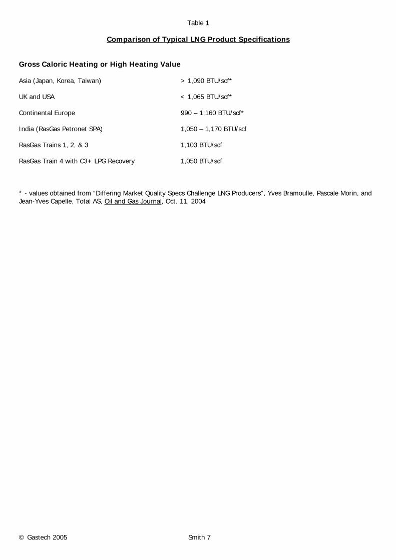
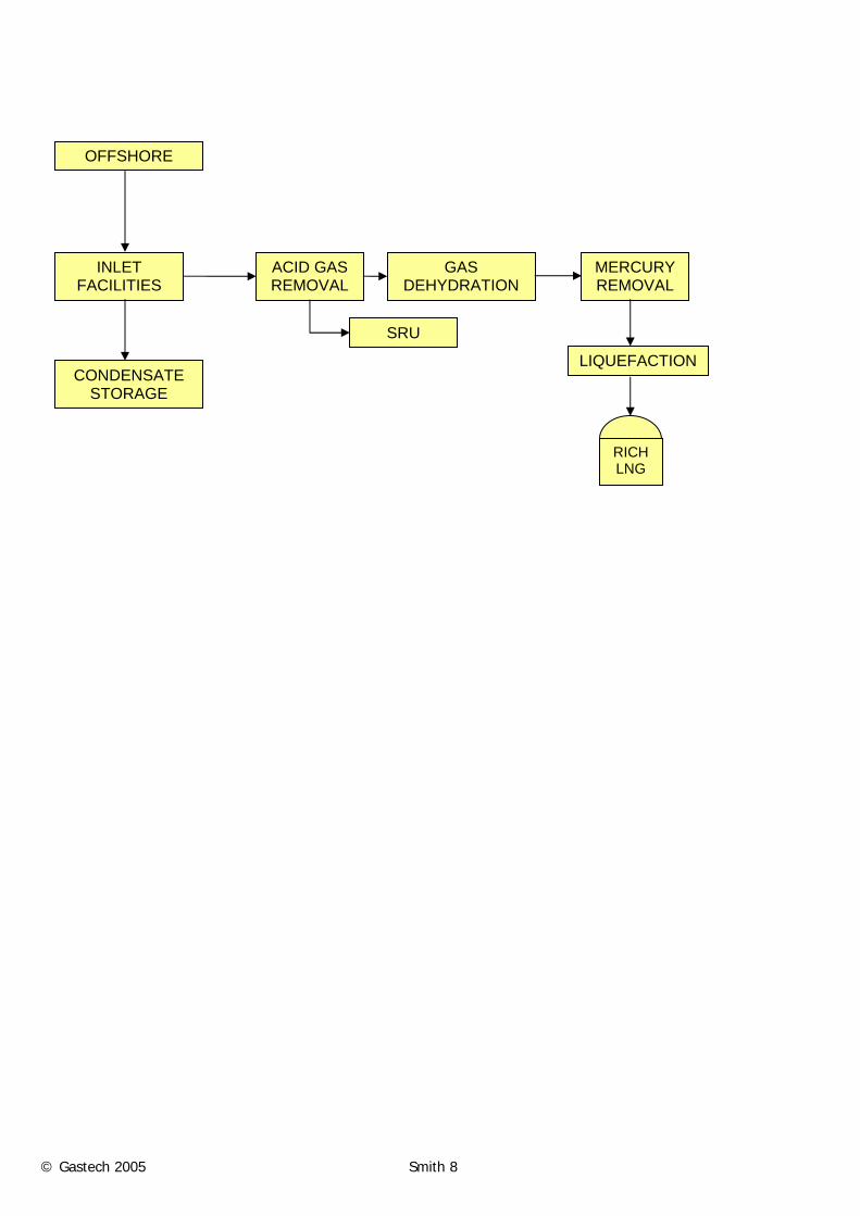
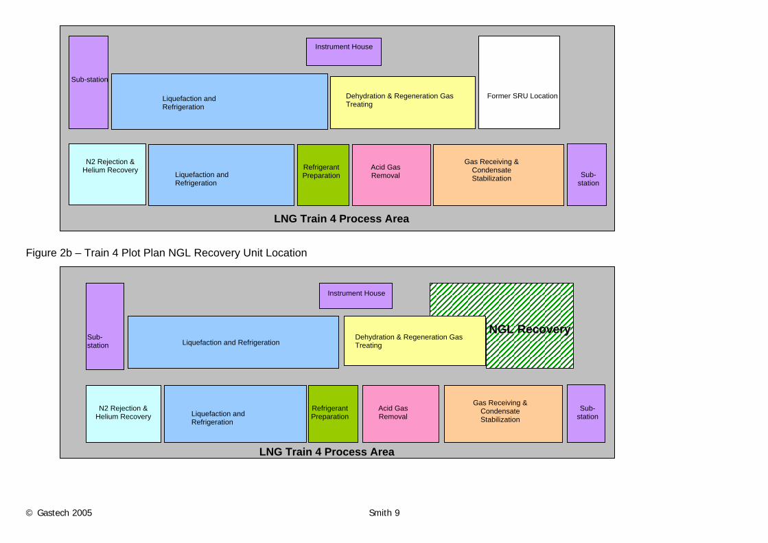
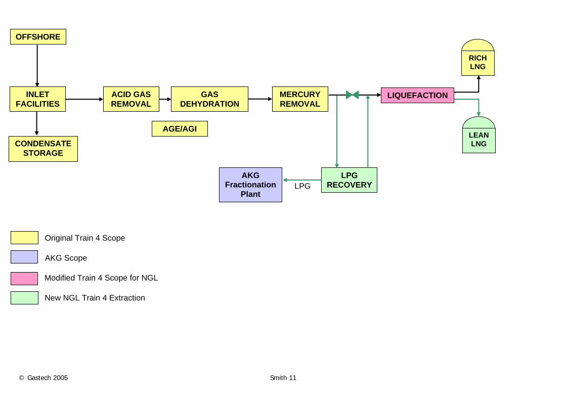
RasGas Company Limited (RasGas) is an incorporated joint venture of Qatar Petroleum and ExxonMobil involved in the production, treatment, liquefaction and transportation of gas from the North Field in Qatar. In 2001 RasGas was operating two large LNG trains and had awarded an engineering, procurement and construction (EPC) contract with the joint venture CMS&A (comprised of Chiyoda, Mitsui, Snamprogetti, and Al-Mana) for two more trains. The first of these two expansion trains (RasGas Train 3) has been in operation since February 2004, and is currently the world’s largest LNG train. The operating and expansion trains were designed to produce a “rich” LNG product to meet the specifications of an Eastern Hemisphere customer base. Consequently, LPGs were not recovered from the LNG feed beyond what was needed for refrigerant make-up. In response to the dynamic LNG market, the opportunity was identified for LNG Train 4 to produce a lower heating value Lean LNG product with resulting LPG production. Processes for extracting natural gas liquids (NGLs) were screened and a process licensed from Ortloff Engineers, Ltd. (Ortloff) was selected. NGL recovery was subsequently incorporated within the already awarded LNG Train 4 EPC work, along with other modifications required to support Lean LNG production, without impact on the contractual Train 4 project schedule. The selected NGL recovery unit was customized to minimize impact on the existing LNG train design while maintaining guaranteed LNG liquefaction capacity despite leaner feed to the liquefaction unit. In addition, the design basis includes the ability to switch between Lean and Rich LNG production modes to meet customer requirements. To accommodate the two different LNG products, modifications to the LNG rundown, storage and loading facilities were also implemented. As of year-end 2004, the Train 4 project was 97% complete and on schedule for completion on or before June 2005. The plant will start-up producing Rich LNG and will switch to Lean LNG with LPG production after completion, in January 2006, of the NGL Recovery Unit, Lean LNG rundown piping and tankage. The design also provides for future ethane recovery in anticipation of a future ethane market in Ras Laffan, Qatar. The Opportunity RasGas LNG expansion trains, like the original two RasGas LNG trains, were designed to meet the specifications of Eastern Hemisphere customers. These customers in Korea and India desired a high heating value LNG product, relatively “rich” in intermediate hydrocarbons. The LNG train process configuration that achieves this is very similar in both the RasGas original and expansion trains, and it excludes natural gas liquid (NGL) recovery as shown in Figure 1. As RasGas was looking to expand LNG marketing, it became clear that a leaner LNG product was more compatible with Western gas consumer requirements. A comparison of RasGas and other typical LNG product specifications is presented in Table 1. LNG Train 4 was being built primarily to meet the demand of a European customer that was willing to take a leaner LNG product. RasGas LNG Train 4 was designed to be essentially identical to LNG Train 3 in order to capture cost and execution time savings associated with design replication. However, Train 4 had one significant difference; the use of acid gas injection in lieu of sulfur recovery. As a result, plot space and certain utilities are available in LNG Train 4 associated with the elimination of the Sulfur Recovery Unit (SRU), as shown in Figure 2. In parallel with development of expansion LNG trains at Ras Laffan, RasGas was also implementing the first phase of the Al Khaleej Gas Project (AKG-1) within the RasGas site. This project includes a large turboexpander-based NGL recovery plant also licensed from Ortloff (with the same inlet capacity as the expansion LNG trains), an NGL fractionation plant, LPG treatment, storage and marine loading facilities. The fractionation plant was designed to accommodate future phases, and exploit economies of scale through a design capacity equal to output of three NGL recovery plants. Together, these features suggested a significant value enhancing opportunity for RasGas associated with production of a Lean LNG product with enhanced marketability. Specifically, if the space and utilities made available by the lack of an SRU could be utilized to incorporate NGL recovery facilities, then the resulting NGL could be transferred to the AKG-1 plant for fractionation, treatment, storage and sales. Initial economics suggested a robust project, and this opportunity was pursued starting in the summer of 2002.
© Gastech 2005 Smith 3
Project Incentives During 2002, project feasibility and process screening studies were initiated in conjunction with marketing studies to define project incentives. The screening studies defined expected LPG product volumes and Lean LNG product characteristics, and provided input to capital cost estimates and economic assessments, while the marketing analysis validated the following project incentives:
• Marketing flexibility – The ability to produce either Rich or Lean LNG products would increase spot LNG sales and therefore increase LNG plant utilization
• LPGs are higher value products (price/BTU) than LNG on a “net back” basis
• Lean LNG production allows access to US East Coast LNG receiving terminals, with better net back pricing than US Gulf Coast terminals due to higher LNG prices and lower shipping costs from Qatar
These incentives were substantial. However economics were significantly enhanced if LNG production could be maintained constant despite NGL recovery. Not only would this allow LPG production to be incremental to (and not instead of) LNG, but the increased offshore production needed to make-up for shrinkage results in additional condensate production. Consequently, maintaining guaranteed LNG production became a key feature of the Train 4 NGL Recovery Project. Project Design Basis Since the Train 4 NGL Recovery Project was defined and implemented after award of the EPC contract for LNG Train 4, it was critical that this supplemental work be executed without impact on the Train 4 project marketing commitments and schedule. These boundaries on the Train 4 NGL Recovery Project are reflected in the project design basis which included the following key components:
• Both the Guaranteed and Ratedi LNG rundown rates (in BTUs/hour) from LNG Train 4 modified to produce Lean LNG were not to be reduced.
• The availability of the modified LNG Train 4 was not to be reduced from the design availability of the as-bid train.
• The schedule for completion of the as-bid LNG Train 4 (i.e., producing Rich LNG) was not to be impacted.
• Modified LNG Train 4 was to be able to produce either a Rich or Lean LNG product.
• Gas liquids recovery would initially be limited to propane and heavier components. However, consideration was to be given to providing the ability for future ethane recovery.
• NGL fractionation, LPG treatment, storage and loading facilities within the AKG-1 project were to be utilized. Project Scope Consistent with the Project Design Basis, the Train 4 NGL Recovery Project includes the following elements:
• A means for recovery of NGLs
• Modifications to LNG Train 4 as required to accommodate NGL recovery
• Separate LNG rundown piping for the new Lean LNG product
• Additional LNG storage and manifolds as needed to accommodate export of two distinct LNG products. Each of these project elements are described below. Execution Plan Execution of the Train 4 NGL Recovery Project is closely linked to the following two projects also being executed by RasGas with the same EPC contractor, CMS&A:
• LNG Train 4 in which the NGL recovery facilities are located. The NGL Recovery Project is therefore dependent upon the LNG Train 4 project for not only supply of treated feed gas, but also provision of utilities. In addition, supplemental LNG offplot facilities (e.g., LNG storage) required for handling Lean LNG are integrated within existing and new offplot facilities being executed as part of LNG Train 4.
© Gastech 2005 Smith 4
• Al Khaleej Gas Project Phase 1 to which raw NGL is sent for fractionation, LPG product storage, metering and port loading.
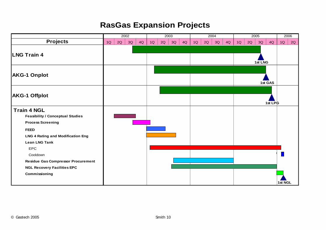
These two projects are being executed together within the RasGas Expansion Project organization. The schedules for those projects, along with the Train 4 NGL Recovery Project, are shown on Figure 3. The following key strategies have been employed in the execution of the Train 4 NGL Recovery Project:
• The NGL Recovery Project facilities are designed to minimize changes to LNG Train 4 facilities, in order to
preserve Train 4 EPC lump sum pricing, but also as a strategy for managing Train 4 schedule risk.
• Priority was given to earliest practical definition and implementation of Train 4 changes. Change Orders to the Train 4 EPC contract were used to expedite implementation.
• Engineering, procurement and construction of the NGL Recovery Facilities were negotiated with the existing EPC contractor in order to minimize interferences with existing project activities.
• RasGas and contractor utilized existing RasGas Expansion Project expertise and integrated this work within the existing project teams.
• Provisions have been made to accommodate future recovery of ethane in the raw NGL. These provisions are designed to allow the necessary facility enhancements to be tied-in within the duration of planned (future) LNG train turnarounds.
• Construction of the NGL Recovery Unit (within LNG Train 4) has been planned and is being executed in a manner that minimizes the extent and type of work that must be undertaken after the initiation of Train 4 operations (in Rich LNG mode), in order to minimize the risks during these simultaneous activities.
The project execution plan, as depicted on the Project Schedule, included a number of overlapping activities designed to minimize project duration. Fast paced execution will achieve the earliest practical start-up, which obviously enhances project economics, but it also helped to manage any changes to LNG Train 4 facilities via early definition and implementation. Key steps in the execution of the Train 4 NGL Recovery Project are listed below:
• Feasibility and marketing studies performed by RasGas
• Parallel NGL recovery process selection studies by competing technology suppliers
• Existing unit Rating Studies conducted by various technology providers and licensers to determine changes that may be required to the LNG Train 4 facilities to accommodate NGL recovery
• Definition and implementation of required Train 4 changes via Change Order(s) to the existing EPC contract
• RasGas procurement of / commitment to long lead turbomachinery and Lean LNG Tank
• Front end engineering and design (FEED) and EPC contracting for new NGL Recovery Project facilities NGL Recovery Process Selection The project design basis defined the key parameters in the NGL Recovery process design selection decision. The primary design variables to consider were:
• Location of the recovery process relative to the LNG Liquefaction Unit’s Scrub Column
• Type of recovery process to use The key parameters considered in the decision making process were:
• Impact on LNG Train 4 completion schedule
• Impact on liquefaction capacity
• Impact on LNG Train 4 availability factor
• LPG recovery efficiency
• Ability to accommodate future ethane recovery
• Cost and schedule
© Gastech 2005 Smith 5
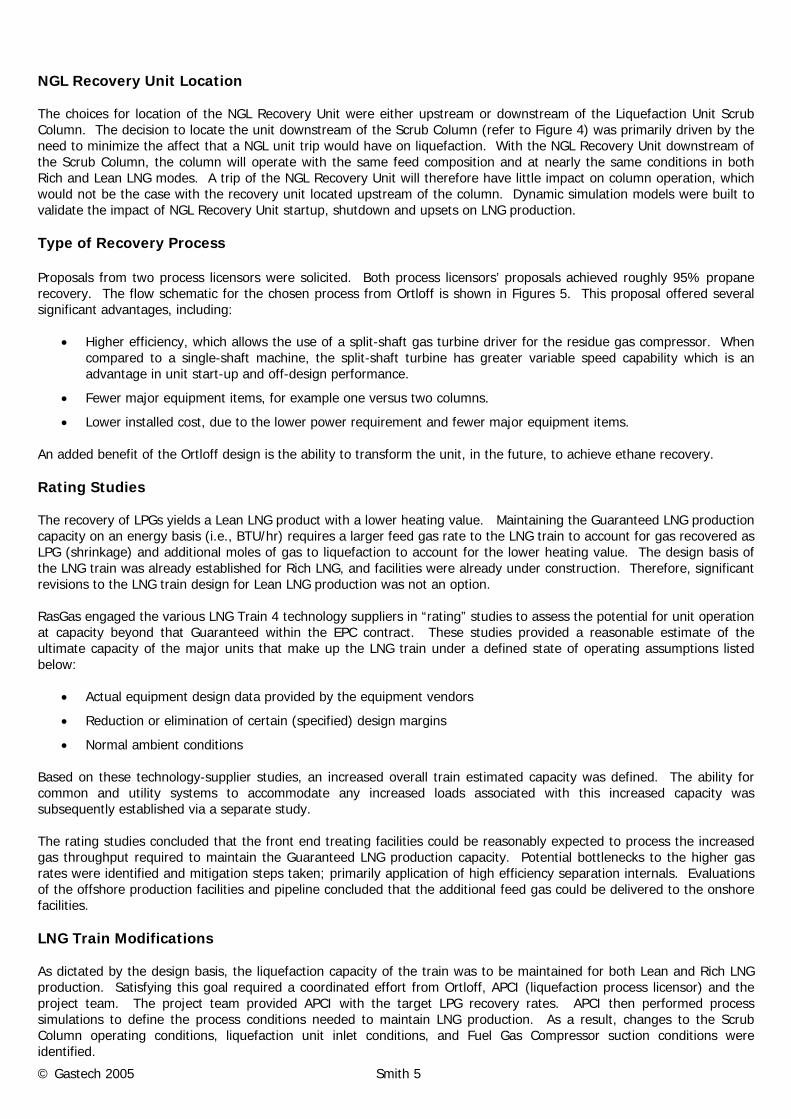
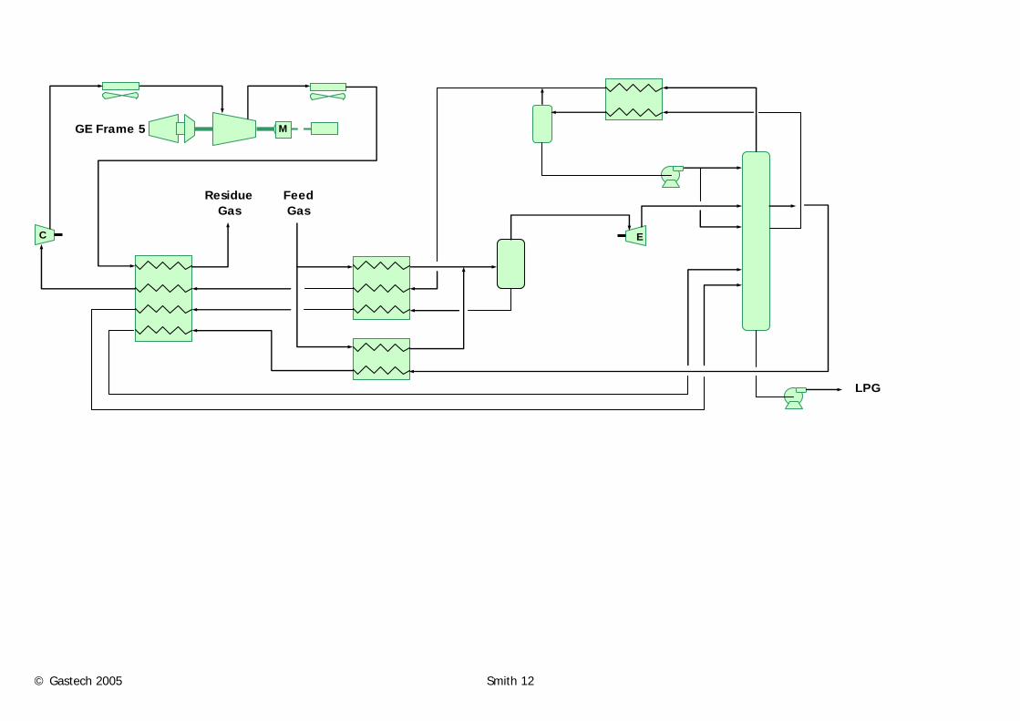
NGL Recovery Unit Location The choices for location of the NGL Recovery Unit were either upstream or downstream of the Liquefaction Unit Scrub Column. The decision to locate the unit downstream of the Scrub Column (refer to Figure 4) was primarily driven by the need to minimize the affect that a NGL unit trip would have on liquefaction. With the NGL Recovery Unit downstream of the Scrub Column, the column will operate with the same feed composition and at nearly the same conditions in both Rich and Lean LNG modes. A trip of the NGL Recovery Unit will therefore have little impact on column operation, which would not be the case with the recovery unit located upstream of the column. Dynamic simulation models were built to validate the impact of NGL Recovery Unit startup, shutdown and upsets on LNG production. Type of Recovery Process Proposals from two process licensors were solicited. Both process licensors’ proposals achieved roughly 95% propane recovery. The flow schematic for the chosen process from Ortloff is shown in Figures 5. This proposal offered several significant advantages, including:
• Higher efficiency, which allows the use of a split-shaft gas turbine driver for the residue gas compressor. When compared to a single-shaft machine, the split-shaft turbine has greater variable speed capability which is an advantage in unit start-up and off-design performance.
• Fewer major equipment items, for example one versus two columns.
• Lower installed cost, due to the lower power requirement and fewer major equipment items. An added benefit of the Ortloff design is the ability to transform the unit, in the future, to achieve ethane recovery. Rating Studies The recovery of LPGs yields a Lean LNG product with a lower heating value. Maintaining the Guaranteed LNG production capacity on an energy basis (i.e., BTU/hr) requires a larger feed gas rate to the LNG train to account for gas recovered as LPG (shrinkage) and additional moles of gas to liquefaction to account for the lower heating value. The design basis of the LNG train was already established for Rich LNG, and facilities were already under construction. Therefore, significant revisions to the LNG train design for Lean LNG production was not an option. RasGas engaged the various LNG Train 4 technology suppliers in “rating” studies to assess the potential for unit operation at capacity beyond that Guaranteed within the EPC contract. These studies provided a reasonable estimate of the ultimate capacity of the major units that make up the LNG train under a defined state of operating assumptions listed below:
• Actual equipment design data provided by the equipment vendors
• Reduction or elimination of certain (specified) design margins
• Normal ambient conditions Based on these technology-supplier studies, an increased overall train estimated capacity was defined. The ability for common and utility systems to accommodate any increased loads associated with this increased capacity was subsequently established via a separate study. The rating studies concluded that the front end treating facilities could be reasonably expected to process the increased gas throughput required to maintain the Guaranteed LNG production capacity. Potential bottlenecks to the higher gas rates were identified and mitigation steps taken; primarily application of high efficiency separation internals. Evaluations of the offshore production facilities and pipeline concluded that the additional feed gas could be delivered to the onshore facilities. LNG Train Modifications As dictated by the design basis, the liquefaction capacity of the train was to be maintained for both Lean and Rich LNG production. Satisfying this goal required a coordinated effort from Ortloff, APCI (liquefaction process licensor) and the project team. The project team provided APCI with the target LPG recovery rates. APCI then performed process simulations to define the process conditions needed to maintain LNG production. As a result, changes to the Scrub Column operating conditions, liquefaction unit inlet conditions, and Fuel Gas Compressor suction conditions were identified.
© Gastech 2005 Smith 6
With the NGL Recovery Unit boundary conditions defined by APCI, Ortloff developed the process design to achieve the desired LPG Recovery rates. A minor amount of iterative work was required between Ortloff and APCI to optimize the design of major rotating equipment. Figures 6 through 8 illustrate the major differences between the original Rich LNG process configuration and operating conditions after modification for NGL Recovery. The objective throughout this work was to minimize mechanical modifications to LNG Train 4 facilities. Lean LNG Rundown and Storage With the production of Lean LNG from LNG Train 4, RasGas becomes a manufacturer of two different LNG products. To accommodate this, LNG rundown, storage and loading facility modifications and additions were implemented as follows:
• An additional LNG Rundown Line for Lean LNG product was added. Train 4’s connection to the Rich LNG Rundown Line was maintained to allow production of either LNG product. As previously mentioned, Train 4’s initial months of operation will be in Rich LNG mode while the NGL Recovery facilities are completed.
• The installation of an additional LNG storage tank was accelerated so as to provide two Lean LNG storage tanks.
• The LNG Tank headers were modified to allow segregation of the Rich and Lean product rundowns and to allow the loading of Rich and Lean LNG at either of the two LNG loading berths.
Conclusions The production of Lean LNG from RasGas LNG Train 4 has allowed RasGas to expand LNG marketing into the growing Western markets of Europe and the United States. This was accomplished by introducing NGL recovery into an already designed plant, for which an EPC contract had been executed. The associated changes were implemented without impact to the base project schedule. By working closely with our contractors and technology licensors, RasGas was able to introduce NGL recovery while maintaining the Guaranteed LNG production rate (on a BTU/hr basis). As a result, in addition to incremental LPG production this project will produce an estimated 14% increase in condensate production. Change is carefully managed by project teams, particularly during the execution of EPC contracts, as they strive to deliver projects on-time and below budget. RasGas’ experience in the implementation of NGL Recovery from LNG Train 4 has shown that significant change can be successfully introduced into lump sum projects, with significant value enhancement to project shareholders. Accomplishing this has required cooperation and teamwork with project contractors, careful planning, and definition of project scope and boundaries to effectively contain and manage changes. Acknowledgements The authors wish to acknowledge the support of RasGas management and shareholders in the development of this paper, as well as the outstanding teamwork demonstrated by all our contractors and technology partners in the execution of this project. In addition, we wish to recognize the significant contributions of Mr. Paul Jones, former RasGas Venture Manager, whose vision was responsible for capturing this opportunity. i In addition to the LNG production Guarantee provided by CMS&A and supported by the process licensors, the project executed extensive “rating” studies during FEED and early EPC to forecast the expected, or “rated”, capacity of the LNG trains. These studies provided key information to validate the potential to extract LPGs from Train 4 without risk to Guaranteed LNG production capacity.
© Gastech 2005 Smith 7
Table 1
Comparison of Typical LNG Product Specifications
Gross Caloric Heating or High Heating Value Asia (Japan, Korea, Taiwan) > 1,090 BTU/scf* UK and USA < 1,065 BTU/scf* Continental Europe 990 – 1,160 BTU/scf* India (RasGas Petronet SPA) 1,050 – 1,170 BTU/scf RasGas Trains 1, 2, & 3 1,103 BTU/scf RasGas Train 4 with C3+ LPG Recovery 1,050 BTU/scf * - values obtained from “Differing Market Quality Specs Challenge LNG Producers”, Yves Bramoulle, Pascale Morin, and Jean-Yves Capelle, Total AS, Oil and Gas Journal, Oct. 11, 2004
© Gastech 2005 Smith 8
INLET FACILITIES
ACID GAS REMOVAL
GAS DEHYDRATION
MERCURY REMOVAL
LIQUEFACTION
RICH LNG
OFFSHORE
SRU
CONDENSATE STORAGE
© Gastech 2005 Smith 9
Figure 2b – Train 4 Plot Plan NGL Recovery Unit Location
Sub-station Liquefaction and Refrigeration
Liquefaction and Refrigeration
N2 Rejection & Helium Recovery
RefrigerantPreparation
Acid Gas Removal
Dehydration & Regeneration Gas Treating
Gas Receiving & Condensate Stabilization
Sub-station
NNGGLL RReeccoovveerryy
Instrument House
LNG Train 4 Process Area
Sub-station Liquefaction and Refrigeration
Liquefaction and Refrigeration
N2 Rejection & Helium Recovery Refrigerant
PreparationAcid Gas Removal
Dehydration & Regeneration Gas Treating
Gas Receiving & Condensate Stabilization Sub-
station
Former SRU Location
Instrument House
LNG Train 4 Process Area
© Gastech 2005 Smith 10
1Q 2Q 3Q 4Q 1Q 2Q 3Q 4Q 1Q 2Q 3Q 4Q 1Q 2Q 3Q 4Q 1Q 2Q
Feasibility / Conceptual Studies
Process Screening
FEED
LNG 4 Rating and Modification Eng
Lean LNG Tank
EPC
Cooldown
Residue Gas Compressor Procurement
NGL Recovery Facilities EPC
Commissioning
AKG-1 Onplot
RasGas Expansion Projects
Train 4 NGL
2006
AKG-1 Offplot
Projects2004 20052002 2003
LNG Train 41st LNG
1st GAS
1st LPG
1st NGL
© Gastech 2005 Smith 11
Original Train 4 Scope
AKG Scope
Modified Train 4 Scope for NGL
New NGL Train 4 Extraction
INLET FACILITIES
ACID GAS REMOVAL
GAS DEHYDRATION
MERCURY REMOVAL
LIQUEFACTION
LPG RECOVERY
AKG Fractionation
Plant LPG
OFFSHORE
AGE/AGI
CONDENSATE STORAGE
RICHLNG
LEANLNG
© Gastech 2005 Smith 12
M
Residue Gas
Feed Gas
LPG
GE Frame 5
EC
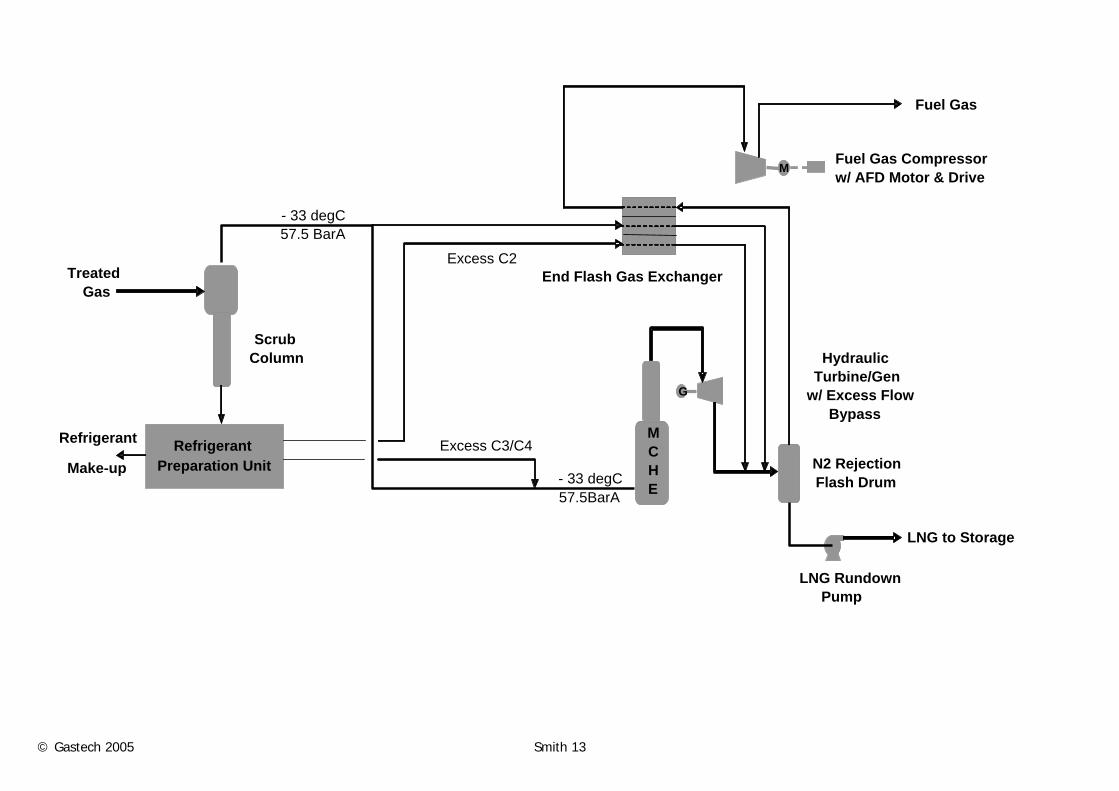
© Gastech 2005 Smith 13
Refrigerant Preparation Unit
G
M
End Flash Gas Exchanger
Fuel Gas Compressor w/ AFD Motor & Drive
HydraulicTurbine/Gen
w/ Excess FlowBypass
LNG RundownPump
N2 RejectionFlash Drum
Excess C3/C4
Scrub Column
MCHE
- 33 degC 57.5BarA
- 33 degC 57.5 BarA
Treated Gas
Refrigerant Make-up
Fuel Gas
LNG to Storage
Excess C2
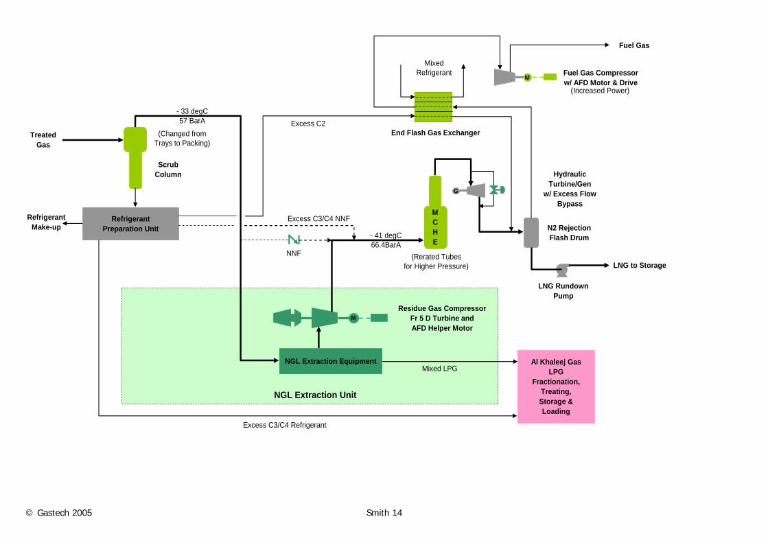
© Gastech 2005 Smith 14
RefrigerantPreparation Unit
NGL Extraction Equipment Al Khaleej Gas LPG
Fractionation, Treating, Storage & Loading
G
M
M
End Flash Gas Exchanger
Fuel Gas Compressorw/ AFD Motor & Drive
Residue Gas CompressorFr 5 D Turbine and AFD Helper Motor
HydraulicTurbine/Gen
w/ Excess FlowBypass
LNG RundownPump
N2 RejectionFlash Drum
NGL Extraction Unit
NNF
Excess C3/C4 NNF
ScrubColumn
Excess C3/C4 Refrigerant
Mixed Refrigerant
(Rerated Tubes for Higher Pressure)
MCHE
Mixed LPG
- 41 degC 66.4BarA
- 33 degC 57 BarA
TreatedGas
RefrigerantMake-up
Fuel Gas
LNG to Storage
Excess C2(Changed from
Trays to Packing)
(Increased Power)
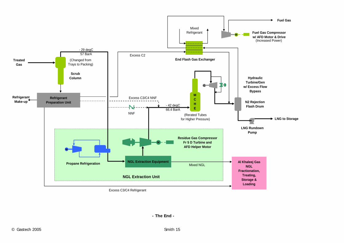
© Gastech 2005 Smith 15
RefrigerantPreparation Unit
NGL Extraction Equipment Al Khaleej Gas NGL
Fractionation, Treating, Storage & Loading
G
M
M
M
End Flash Gas Exchanger
Fuel Gas Compressorw/ AFD Motor & Drive
Residue Gas CompressorFr 5 D Turbine and AFD Helper Motor
HydraulicTurbine/Gen
w/ Excess FlowBypass
LNG RundownPump
N2 RejectionFlash Drum
Propane Refrigeration
NGL Extraction Unit
NNF
Excess C3/C4 NNF
ScrubColumn
Excess C3/C4 Refrigerant
Mixed Refrigerant
(Rerated Tubes for Higher Pressure)
MCHE
Mixed NGL
- 42 degC 66.4 BarA
- 29 degC 57 BarA
TreatedGas
RefrigerantMake-up
Fuel Gas
LNG to Storage
Excess C2(Changed from
Trays to Packing)
(Increased Power)
- The End -