capacitor bank protection and control rev615 application manual
TRANSCRIPT

Relion® 615 series
Capacitor Bank Protection and ControlREV615Application Manual


Document ID: 1MRS757946Issued: 2016-05-20
Revision: CProduct version: 5.0 FP1
© Copyright 2016 ABB. All rights reserved

Copyright
This document and parts thereof must not be reproduced or copied without writtenpermission from ABB, and the contents thereof must not be imparted to a third party,nor used for any unauthorized purpose.
The software or hardware described in this document is furnished under a license andmay be used, copied, or disclosed only in accordance with the terms of such license.
TrademarksABB and Relion are registered trademarks of the ABB Group. All other brand orproduct names mentioned in this document may be trademarks or registeredtrademarks of their respective holders.
WarrantyPlease inquire about the terms of warranty from your nearest ABB representative.
http://www.abb.com/substationautomation

Disclaimer
The data, examples and diagrams in this manual are included solely for the concept orproduct description and are not to be deemed as a statement of guaranteed properties.All persons responsible for applying the equipment addressed in this manual mustsatisfy themselves that each intended application is suitable and acceptable, includingthat any applicable safety or other operational requirements are complied with. Inparticular, any risks in applications where a system failure and/or product failurewould create a risk for harm to property or persons (including but not limited topersonal injuries or death) shall be the sole responsibility of the person or entityapplying the equipment, and those so responsible are hereby requested to ensure thatall measures are taken to exclude or mitigate such risks.
This product has been designed to be connected and communicate data andinformation via a network interface which should be connected to a secure network.It is the sole responsibility of the person or entity responsible for networkadministration to ensure a secure connection to the network and to take the necessarymeasures (such as, but not limited to, installation of firewalls, application ofauthentication measures, encryption of data, installation of anti virus programs, etc.)to protect the product and the network, its system and interface included, against anykind of security breaches, unauthorized access, interference, intrusion, leakage and/ortheft of data or information. ABB is not liable for any such damages and/or losses.
This document has been carefully checked by ABB but deviations cannot becompletely ruled out. In case any errors are detected, the reader is kindly requested tonotify the manufacturer. Other than under explicit contractual commitments, in noevent shall ABB be responsible or liable for any loss or damage resulting from the useof this manual or the application of the equipment.

Conformity
This product complies with the directive of the Council of the European Communitieson the approximation of the laws of the Member States relating to electromagneticcompatibility (EMC Directive 2004/108/EC) and concerning electrical equipment foruse within specified voltage limits (Low-voltage directive 2006/95/EC). Thisconformity is the result of tests conducted by ABB in accordance with the productstandard EN 60255-26 for the EMC directive, and with the product standards EN60255-1 and EN 60255-27 for the low voltage directive. The product is designed inaccordance with the international standards of the IEC 60255 series.

Table of contents
Section 1 Introduction.......................................................................5This manual........................................................................................ 5Intended audience.............................................................................. 5Product documentation.......................................................................6
Product documentation set............................................................6Document revision history............................................................. 6Related documentation..................................................................7
Symbols and conventions...................................................................7Symbols.........................................................................................7Document conventions..................................................................8Functions, codes and symbols...................................................... 8
Section 2 REV615 overview...........................................................13Overview...........................................................................................13
Product version history................................................................13PCM600 and relay connectivity package version........................14
Operation functionality......................................................................14Optional functions........................................................................14
Physical hardware............................................................................ 15Local HMI......................................................................................... 16
Display.........................................................................................17LEDs............................................................................................18Keypad........................................................................................ 18
Web HMI...........................................................................................19Authorization.....................................................................................20
Audit trail......................................................................................21Communication.................................................................................23
Self-healing Ethernet ring............................................................24Ethernet redundancy................................................................... 25Process bus.................................................................................27Secure communication................................................................29
Section 3 REV615 standard configurations................................... 31Standard configurations....................................................................31
Addition of control functions for primary devices and the useof binary inputs and outputs........................................................ 33
Connection diagrams........................................................................34Standard configuration A.................................................................. 35
Applications................................................................................. 35Functions.....................................................................................37
Table of contents
REV615 1Application Manual

Default I/O connections.......................................................... 37Default disturbance recorder settings.....................................39
Functional diagrams.................................................................... 40Functional diagrams for protection ........................................ 41Functional diagrams for disturbance recorder........................47Functional diagrams for condition monitoring.........................48Functional diagrams for control and interlocking....................50Functional diagrams for measurement functions................... 53Functional diagrams for I/O and alarms LEDs ...................... 55Functional diagrams for other timer logics............................. 58Other functions ...................................................................... 59
Standard configuration B.................................................................. 59Applications................................................................................. 59Functions.....................................................................................60
Default I/O connections.......................................................... 61Default disturbance recorder settings.....................................62
Functional diagrams.................................................................... 64Functional diagrams for protection ........................................ 64Functional diagrams for disturbance recorder........................74Functional diagrams for condition monitoring.........................74Functional diagrams for control and interlocking....................76Functional diagrams for measurement functions................... 79Functional diagrams for I/O and alarms LEDs ...................... 82Functional diagrams for other timer logics............................. 85Other functions ...................................................................... 86
Section 4 Requirements for measurement transformers................87Current transformers........................................................................ 87
Current transformer requirements for non-directionalovercurrent protection..................................................................87
Current transformer accuracy class and accuracy limitfactor...................................................................................... 87Non-directional overcurrent protection................................... 88Example for non-directional overcurrent protection................89
Section 5 IED physical connections............................................... 91Inputs................................................................................................91
Energizing inputs.........................................................................91Phase currents....................................................................... 91Residual current..................................................................... 91Phase voltages.......................................................................91Residual voltage.....................................................................92
Auxiliary supply voltage input...................................................... 92Binary inputs................................................................................92
Table of contents
2 REV615Application Manual

Optional light sensor inputs......................................................... 94RTD/mA inputs............................................................................ 94
Outputs............................................................................................. 95Outputs for tripping and controlling..............................................95Outputs for signalling...................................................................96IRF...............................................................................................97
Section 6 Glossary......................................................................... 99
Table of contents
REV615 3Application Manual

4

Section 1 Introduction
1.1 This manual
The application manual contains application descriptions and setting guidelinessorted per function. The manual can be used to find out when and for what purpose atypical protection function can be used. The manual can also be used when calculatingsettings.
1.2 Intended audience
This manual addresses the protection and control engineer responsible for planning,pre-engineering and engineering.
The protection and control engineer must be experienced in electrical powerengineering and have knowledge of related technology, such as protection schemesand principles.
1MRS757946 C Section 1Introduction
REV615 5Application Manual

1.3 Product documentation
1.3.1 Product documentation set
Pla
nnin
g &
pu
rcha
se
Eng
inee
ring
Inst
alla
tion
Com
mis
sion
ing
Ope
ratio
n
Mai
nten
ance
Dec
omm
issi
onin
g,
dein
stal
latio
n &
dis
posa
l
Quick start guideQuick installation guideBrochureProduct guideOperation manualInstallation manualConnection diagramEngineering manualTechnical manualApplication manualCommunication protocol manualIEC 61850 engineering guidePoint list manualCyber security deployment guideline
GUID-12DC16B2-2DC1-48DF-8734-0C8B7116124C V2 EN
Figure 1: The intended use of documents during the product life cycle
Product series- and product-specific manuals can be downloadedfrom the ABB Web site http://www.abb.com/relion.
1.3.2 Document revision historyDocument revision/date Product version HistoryA/2014-01-24 5.0 First release
B/2015-10-30 5.0 FP1 Content updated to correspond to theproduct version
C/2016-05-20 5.0 FP1 Content updated
Download the latest documents from the ABB Web sitehttp://www.abb.com/substationautomation.
Section 1 1MRS757946 CIntroduction
6 REV615Application Manual

1.3.3 Related documentationName of the document Document IDModbus Communication Protocol Manual 1MRS756468
DNP3 Communication Protocol Manual 1MRS756709
IEC 60870-5-103 Communication Protocol Manual 1MRS756710
IEC 61850 Engineering Guide 1MRS756475
Engineering Manual 1MRS757121
Installation Manual 1MRS756375
Operation Manual 1MRS756708
Technical Manual 1MRS756887
Cyber Security Deployment Guideline 1MRS758280
1.4 Symbols and conventions
1.4.1 Symbols
The electrical warning icon indicates the presence of a hazard whichcould result in electrical shock.
The warning icon indicates the presence of a hazard which couldresult in personal injury.
The caution icon indicates important information or warning relatedto the concept discussed in the text. It might indicate the presence ofa hazard which could result in corruption of software or damage toequipment or property.
The information icon alerts the reader of important facts andconditions.
The tip icon indicates advice on, for example, how to design yourproject or how to use a certain function.
Although warning hazards are related to personal injury, it is necessary to understandthat under certain operational conditions, operation of damaged equipment may result
1MRS757946 C Section 1Introduction
REV615 7Application Manual

in degraded process performance leading to personal injury or death. Therefore,comply fully with all warning and caution notices.
1.4.2 Document conventions
A particular convention may not be used in this manual.
• Abbreviations and acronyms are spelled out in the glossary. The glossary alsocontains definitions of important terms.
• Push button navigation in the LHMI menu structure is presented by using thepush button icons.To navigate between the options, use and .
• Menu paths are presented in bold.Select Main menu/Settings.
• LHMI messages are shown in Courier font.To save the changes in nonvolatile memory, select Yes and press .
• Parameter names are shown in italics.The function can be enabled and disabled with the Operation setting.
• Parameter values are indicated with quotation marks.The corresponding parameter values are "On" and "Off".
• Input/output messages and monitored data names are shown in Courier font.When the function starts, the START output is set to TRUE.
• This document assumes that the parameter setting visibility is "Advanced".
1.4.3 Functions, codes and symbolsTable 1: Functions included in the relay
Function IEC 61850 IEC 60617 IEC-ANSIProtection
Three-phase non-directionalovercurrent protection, low stage
PHLPTOC1 3I> (1) 51P-1 (1)
Three-phase non-directionalovercurrent protection, high stage
PHHPTOC1 3I>> (1) 51P-2 (1)
PHHPTOC2 3I>> (2) 51P-2 (2)
Three-phase non-directionalovercurrent protection, instantaneousstage
PHIPTOC1 3I>>> (1) 50P/51P (1)
Non-directional earth-fault protection,low stage
EFLPTOC1 Io> (1) 51N-1 (1)
EFLPTOC2 Io> (2) 51N-1 (2)
Non-directional earth-fault protection,high stage
EFHPTOC1 Io>> (1) 51N-2 (1)
Non-directional earth-fault protection,instantaneous stage
EFIPTOC1 Io>>> (1) 50N/51N (1)
Directional earth-fault protection, lowstage
DEFLPDEF1 Io> -> (1) 67N-1 (1)
DEFLPDEF2 Io> -> (2) 67N-1 (2)
Table continues on next page
Section 1 1MRS757946 CIntroduction
8 REV615Application Manual

Function IEC 61850 IEC 60617 IEC-ANSIDirectional earth-fault protection, highstage
DEFHPDEF1 Io>> -> (1) 67N-2 (1)
Transient/intermittent earth-faultprotection
INTRPTEF1 Io> -> IEF (1) 67NIEF (1)
Negative-sequence overcurrentprotection
NSPTOC1 I2> (1) 46 (1)
NSPTOC2 I2> (2) 46 (2)
Residual overvoltage protection ROVPTOV1 Uo> (1) 59G (1)
ROVPTOV2 Uo> (2) 59G (2)
ROVPTOV3 Uo> (3) 59G (3)
Three-phase undervoltage protection PHPTUV1 3U< (1) 27 (1)
PHPTUV2 3U< (2) 27 (2)
Three-phase overvoltage protection PHPTOV1 3U> (1) 59 (1)
PHPTOV2 3U> (2) 59 (2)
Positive-sequence undervoltageprotection
PSPTUV1 U1< (1) 47U+ (1)
Negative-sequence overvoltageprotection
NSPTOV1 U2> (1) 47O- (1)
Three-phase thermal overloadprotection, two time constants
T2PTTR1 3Ith>T/G/C (1) 49T/G/C (1)
Circuit breaker failure protection CCBRBRF1 3I>/Io>BF (1) 51BF/51NBF (1)
Master trip TRPPTRC1 Master Trip (1) 94/86 (1)
TRPPTRC2 Master Trip (2) 94/86 (2)
TRPPTRC3 Master Trip (3) 94/86 (3)
TRPPTRC4 Master Trip (4) 94/86 (4)
TRPPTRC5 Master Trip (5) 94/86 (5)
Arc protection ARCSARC1 ARC (1) 50L/50NL (1)
ARCSARC2 ARC (2) 50L/50NL (2)
ARCSARC3 ARC (3) 50L/50NL (3)
Table continues on next page
1MRS757946 C Section 1Introduction
REV615 9Application Manual

Function IEC 61850 IEC 60617 IEC-ANSIMultipurpose protection MAPGAPC1 MAP (1) MAP (1)
MAPGAPC2 MAP (2) MAP (2)
MAPGAPC3 MAP (3) MAP (3)
MAPGAPC4 MAP (4) MAP (4)
MAPGAPC5 MAP (5) MAP (5)
MAPGAPC6 MAP (6) MAP (6)
MAPGAPC7 MAP (7) MAP (7)
MAPGAPC8 MAP (8) MAP (8)
MAPGAPC9 MAP (9) MAP (9)
MAPGAPC10 MAP (10) MAP (10)
MAPGAPC11 MAP (11) MAP (11)
MAPGAPC12 MAP (12) MAP (12)
MAPGAPC13 MAP (13) MAP (13)
MAPGAPC14 MAP (14) MAP (14)
MAPGAPC15 MAP (15) MAP (15)
MAPGAPC16 MAP (16) MAP (16)
MAPGAPC17 MAP (17) MAP (17)
MAPGAPC18 MAP (18) MAP (18)
Three-phase overload protection forshunt capacitor banks
COLPTOC1 3I> 3I< (1) 51C/37 (1)
Current unbalance protection for shuntcapacitor banks
CUBPTOC1 dI>C (1) 51NC-1 (1)
Three-phase current unbalanceprotection for shunt capacitor banks
HCUBPTOC1 3dI>C (1) 51NC-2 (1)
Shunt capacitor bank switchingresonance protection, current based
SRCPTOC1 TD> (1) 55TD (1)
Power quality
Current total demand distortion CMHAI1 PQM3I (1) PQM3I (1)
Voltage total harmonic distortion VMHAI1 PQM3U (1) PQM3V (1)
Voltage variation PHQVVR1 PQMU (1) PQMV (1)
Voltage unbalance VSQVUB1 PQUUB (1) PQVUB (1)
Control
Circuit-breaker control CBXCBR1 I <-> O CB (1) I <-> O CB (1)
Disconnector control DCXSWI1 I <-> O DCC (1) I <-> O DCC (1)
DCXSWI2 I <-> O DCC (2) I <-> O DCC (2)
Earthing switch control ESXSWI1 I <-> O ESC (1) I <-> O ESC (1)
Disconnector position indication DCSXSWI1 I <-> O DC (1) I <-> O DC (1)
DCSXSWI2 I <-> O DC (2) I <-> O DC (2)
DCSXSWI3 I <-> O DC (3) I <-> O DC (3)
Earthing switch indication ESSXSWI1 I <-> O ES (1) I <-> O ES (1)
ESSXSWI2 I <-> O ES (2) I <-> O ES (2)
Table continues on next page
Section 1 1MRS757946 CIntroduction
10 REV615Application Manual

Function IEC 61850 IEC 60617 IEC-ANSICondition monitoring and supervision
Circuit-breaker condition monitoring SSCBR1 CBCM (1) CBCM (1)
Trip circuit supervision TCSSCBR1 TCS (1) TCM (1)
TCSSCBR2 TCS (2) TCM (2)
Current circuit supervision CCSPVC1 MCS 3I (1) MCS 3I (1)
Fuse failure supervision SEQSPVC1 FUSEF (1) 60 (1)
Runtime counter for machines anddevices
MDSOPT1 OPTS (1) OPTM (1)
Measurement
Disturbance recorder RDRE1 DR (1) DFR (1)
Load profile record LDPRLRC1 LOADPROF (1) LOADPROF (1)
Fault record FLTRFRC1 FAULTREC (1) FAULTREC (1)
Three-phase current measurement CMMXU1 3I (1) 3I (1)
Sequence current measurement CSMSQI1 I1, I2, I0 (1) I1, I2, I0 (1)
Residual current measurement RESCMMXU1 Io (1) In (1)
Three-phase voltage measurement VMMXU1 3U (1) 3V (1)
Residual voltage measurement RESVMMXU1 Uo (1) Vn (1)
RESVMMXU2 Uo (2) Vn (2)
Sequence voltage measurement VSMSQI1 U1, U2, U0 (1) V1, V2, V0 (1)
Three-phase power and energymeasurement
PEMMXU1 P, E (1) P, E (1)
RTD/mA measurement XRGGIO130 X130 (RTD) (1) X130 (RTD) (1)
Frequency measurement FMMXU1 f (1) f (1)
IEC 61850-9-2 LE sampled valuesending
SMVSENDER SMVSENDER SMVSENDER
IEC 61850-9-2 LE sampled valuereceiving (voltage sharing)
SMVRCV SMVRCV SMVRCV
Other
Minimum pulse timer (2 pcs) TPGAPC1 TP (1) TP (1)
TPGAPC2 TP (2) TP (2)
TPGAPC3 TP (3) TP (3)
TPGAPC4 TP (4) TP (4)
Minimum pulse timer (2 pcs, secondresolution)
TPSGAPC1 TPS (1) TPS (1)
Minimum pulse timer (2 pcs, minuteresolution)
TPMGAPC1 TPM (1) TPM (1)
Pulse timer (8 pcs) PTGAPC1 PT (1) PT (1)
PTGAPC2 PT (2) PT (2)
Time delay off (8 pcs) TOFGAPC1 TOF (1) TOF (1)
TOFGAPC2 TOF (2) TOF (2)
TOFGAPC3 TOF (3) TOF (3)
TOFGAPC4 TOF (4) TOF (4)
Table continues on next page
1MRS757946 C Section 1Introduction
REV615 11Application Manual

Function IEC 61850 IEC 60617 IEC-ANSITime delay on (8 pcs) TONGAPC1 TON (1) TON (1)
TONGAPC2 TON (2) TON (2)
TONGAPC3 TON (3) TON (3)
TONGAPC4 TON (4) TON (4)
Set-reset (8 pcs) SRGAPC1 SR (1) SR (1)
SRGAPC2 SR (2) SR (2)
SRGAPC3 SR (3) SR (3)
SRGAPC4 SR (4) SR (4)
Move (8 pcs) MVGAPC1 MV (1) MV (1)
MVGAPC2 MV (2) MV (2)
Generic control point (16 pcs) SPCGAPC1 SPC (1) SPC (1)
SPCGAPC2 SPC (2) SPC (2)
Analog value scaling SCA4GAPC1 SCA4 (1) SCA4 (1)
SCA4GAPC2 SCA4 (2) SCA4 (2)
SCA4GAPC3 SCA4 (3) SCA4 (3)
SCA4GAPC4 SCA4 (4) SCA4 (4)
Integer value move MVI4GAPC1 MVI4 (1) MVI4 (1)
Section 1 1MRS757946 CIntroduction
12 REV615Application Manual

Section 2 REV615 overview
2.1 Overview
REV615 is a dedicated capacitor bank relay designed for the protection, control,measurement and supervision of capacitor banks used for compensation of reactivepower in utility substations and industrial power systems. REV615 can also be usedfor protection of harmonic filter circuits, if the highest significant harmoniccomponent is the 11th. REV615 is a member of ABB’s Relion® product family andpart of its 615 protection and control product series. The 615 series relays arecharacterized by their compactness and withdrawable-unit design.
Re-engineered from the ground up, the 615 series has been designed to unleash the fullpotential of the IEC 61850 standard for communication and interoperability betweensubstation automation devices.
The relay provides main protection for single star, double star, and H-bridgeconnected capacitor banks and harmonic filters in distribution networks.
Depending on the chosen standard configuration, the relay is adapted for theprotection of H-bridge connected or double star connected shunt capacitor banks.Once the standard configuration relay has been given the application-specific settings,it can directly be put into service.
The 615 series relays support a range of communication protocols including IEC61850 with Edition 2 support, process bus according to IEC 61850-9-2 LE, IEC60870-5-103, Modbus® and DNP3. Profibus DPV1 communication protocol issupported by using the protocol converter SPA-ZC 302.
2.1.1 Product version historyProduct version Product history5.0 Product released
5.0 FP1 • IEC 61850 Edition 2• Currents sending support with IEC 61850-9-2 LE• Support for configuration migration (starting from Ver.3.0 to Ver.5.0 FP1)• Software closable Ethernet ports• Chinese language support• Report summary via WHMI• Voltage unbalance power quality option• Residual current input 0.2/1 A option• Transient/intermittent E/F• Additional timer, set-reset and analog value scaling functions
1MRS757946 C Section 2REV615 overview
REV615 13Application Manual

2.1.2 PCM600 and relay connectivity package version
• Protection and Control IED Manager PCM600 2.6 (Rollup 20150626) or later• REV615 Connectivity Package Ver.5.1 or later
• Parameter Setting• Signal Monitoring• Event Viewer• Disturbance Handling• Application Configuration• Signal Matrix• Graphical Display Editor• Communication Management• IED User Management• IED Compare• Firmware Update• Fault Record tool• Load Record Profile• Lifecycle Traceability• Configuration Wizard• AR Sequence Visualizer• Label Printing• IEC 61850 Configuration• IED Configuration Migration
Download connectivity packages from the ABB Web sitehttp://www.abb.com/substationautomation or directly with theUpdate Manager in PCM600.
2.2 Operation functionality
2.2.1 Optional functions
• Modbus TCP/IP or RTU/ASCII• IEC 60870-5-103• DNP3 TCP/IP or serial• Power quality functions• IEC 61850-9-2 LE• IEEE 1588 v2 time synchronization
Section 2 1MRS757946 CREV615 overview
14 REV615Application Manual

2.3 Physical hardware
The protection relay consists of two main parts: plug-in unit and case. The contentdepends on the ordered functionality.
Table 2: Plug-in unit and case
Main Slot ID Content optionsPlug-inunit
- HMI Small (5 lines, 20 characters)Large (10 lines, 20 characters) with SLD
Small Chinese (3 lines, 8 or more characters)Large Chinese (7 lines, 8 or more characters) withSLD
X100 Auxiliary power/BOmodule
48-250V DC/100-240 V AC; or 24-60 V DC2 normally-open PO contacts1 change-over SO contact1 normally open SO contact2 double-pole PO contacts with TCS1 dedicated internal fault output contact
X110 BIO module 8 binary inputs4 SO contacts
8 binary inputs3 HSO contacts
X120 AI module 6 phase current inputs (1/5 A)1 residual current input (1/5 A or 0.2/1 A) 1)
Case X130 AI/BI module Only with configuration B:3 phase voltage inputs (60-210 V)1 residual voltage input (60-210 V)1 reference voltage input for ROV2 and ROV3(60-210 V)4 binary inputs
AI/RTD/mA module Only with configuration B:3 phase voltage inputs (60-210 V)1 residual voltage input (60-210 V)1 reference voltage input for ROV2 and ROV3(60-210 V)1 generic mA input2 RTD sensor inputs
Optional BIOmodule Optional for configuration A:6 binary inputs3 SO contacts
Optional RTD/mA module Optional for configuration A:2 generic mA inputs6 RTD sensor inputs
X000 Optional communicationmodule
See the technical manual for details about differenttypes of communication modules.
1) The 0.2/1 A input is normally used in applications requiring sensitive earth-fault protection and featuringcore-balance current transformers.
Rated values of the current and voltage inputs are basic setting parameters of theprotection relay. The binary input thresholds are selectable within the range 16…176V DC by adjusting the binary input setting parameters.
1MRS757946 C Section 2REV615 overview
REV615 15Application Manual

The connection diagrams of different hardware modules are presented in this manual.
See the installation manual for more information about the case andthe plug-in unit.
Table 3: Input/output overview
Std. conf. Order code digit Analog channels Binary channels 5-6 7-8 CT VT BI BO RTD mA
A
BA
BA 7 - 8 4 PO + 6SO
- -
BB 7 - 14 4 PO + 9SO
- -
FD 7 - 8 4 PO + 2SO + 3HSO
- -
FF 7 - 14 4 PO + 5SO + 3HSO
- -
BG
BA 7 - 8 4 PO + 6SO
6 2
FD 7 - 8 4 PO + 2SO + 3HSO
6 2
B
BC
AD 7 5 12 4 PO + 6SO
- -
FE 7 5 12 4 PO + 2SO + 3HSO
- -
BE
BA 7 5 8 4 PO + 6SO
2 1
FD 7 5 8 4 PO + 2SO + 3HSO
2 1
2.4 Local HMI
The LHMI is used for setting, monitoring and controlling the protection relay. TheLHMI comprises the display, buttons, LED indicators and communication port.
Section 2 1MRS757946 CREV615 overview
16 REV615Application Manual

REF615
Overcurrent
Dir. earth-fault
Voltage protection
Phase unbalance
Thermal overload
Breaker failure
Disturb. rec. Triggered
CB condition monitoring
Supervision
Arc detected
Autoreclose shot in progr.
A070704 V4 EN
Figure 2: Example of the LHMI
2.4.1 Display
The LHMI includes a graphical display that supports two character sizes. Thecharacter size depends on the selected language. The amount of characters and rowsfitting the view depends on the character size.
Table 4: Small display
Character size1) Rows in the view Characters per row
Small, mono-spaced (6 × 12 pixels) 5 20
Large, variable width (13 × 14 pixels) 3 8 or more
1) Depending on the selected language
Table 5: Large display
Character size1) Rows in the view Characters per row
Small, mono-spaced (6 × 12 pixels) 10 20
Large, variable width (13 × 14 pixels) 7 8 or more
1) Depending on the selected language
1MRS757946 C Section 2REV615 overview
REV615 17Application Manual

The display view is divided into four basic areas.
1 2
3 4A070705 V3 EN
Figure 3: Display layout
1 Header
2 Icon
3 Content
4 Scroll bar (displayed when needed)
2.4.2 LEDs
The LHMI includes three protection indicators above the display: Ready, Start andTrip.
There are 11 matrix programmable LEDs on front of the LHMI. The LEDs can beconfigured with PCM600 and the operation mode can be selected with the LHMI,WHMI or PCM600.
2.4.3 Keypad
The LHMI keypad contains push buttons which are used to navigate in different viewsor menus. With the push buttons you can give open or close commands to objects inthe primary circuit, for example, a circuit breaker, a contactor or a disconnector. Thepush buttons are also used to acknowledge alarms, reset indications, provide help andswitch between local and remote control mode.
Section 2 1MRS757946 CREV615 overview
18 REV615Application Manual

A071176 V1 EN
Figure 4: LHMI keypad with object control, navigation and command pushbuttons and RJ-45 communication port
2.5 Web HMI
The WHMI allows secure access to the protection relay via a Web browser. When theSecure Communication parameter in the protection relay is activated, the Web serveris forced to take a secured (HTTPS) connection to WHMI using TLS encryption.TheWHMI is verified with Internet Explorer 8.0, 9.0, 10.0 and 11.0.
WHMI is disabled by default.
WHMI offers several functions.
• Programmable LEDs and event lists• System supervision• Parameter settings• Measurement display• Disturbance records• Fault records• Load profile record• Phasor diagram• Single-line diagram• Importing/Exporting parameters• Report summary
The menu tree structure on the WHMI is almost identical to the one on the LHMI.
1MRS757946 C Section 2REV615 overview
REV615 19Application Manual

A070754 V6 EN
Figure 5: Example view of the WHMI
The WHMI can be accessed locally and remotely.
• Locally by connecting the laptop to the protection relay via the frontcommunication port.
• Remotely over LAN/WAN.
2.6 Authorization
Four user categories have been predefined for the LHMI and the WHMI, each withdifferent rights and default passwords.
The default passwords in the protection relay delivered from the factory can bechanged with Administrator user rights.
User authorization is disabled by default for LHMI but WHMI alwaysuses authorization.
Section 2 1MRS757946 CREV615 overview
20 REV615Application Manual

Table 6: Predefined user categories
Username User rightsVIEWER Read only access
OPERATOR • Selecting remote or local state with (only locally)• Changing setting groups• Controlling• Clearing indications
ENGINEER • Changing settings• Clearing event list• Clearing disturbance records• Changing system settings such as IP address, serial baud rate or
disturbance recorder settings• Setting the protection relay to test mode• Selecting language
ADMINISTRATOR • All listed above• Changing password• Factory default activation
For user authorization for PCM600, see PCM600 documentation.
2.6.1 Audit trail
The protection relay offers a large set of event-logging functions. Critical system andprotection relay security-related events are logged to a separate nonvolatile audit trailfor the administrator.
Audit trail is a chronological record of system activities that allows the reconstructionand examination of the sequence of system and security-related events and changes inthe protection relay. Both audit trail events and process related events can beexamined and analyzed in a consistent method with the help of Event List in LHMIand WHMI and Event Viewer in PCM600.
The protection relay stores 2048 audit trail events to the nonvolatile audit trail.Additionally, 1024 process events are stored in a nonvolatile event list. Both the audittrail and event list work according to the FIFO principle. Nonvolatile memory is basedon a memory type which does not need battery backup nor regular component changeto maintain the memory storage.
Audit trail events related to user authorization (login, logout, violation remote andviolation local) are defined according to the selected set of requirements from IEEE1686. The logging is based on predefined user names or user categories. The user audittrail events are accessible with IEC 61850-8-1, PCM600, LHMI and WHMI.
1MRS757946 C Section 2REV615 overview
REV615 21Application Manual

Table 7: Audit trail events
Audit trail event DescriptionConfiguration change Configuration files changed
Firmware change Firmware changed
Firmware change fail Firmware change failed
Attached to retrofit test case Unit has been attached to retrofit case
Removed from retrofit test case Removed from retrofit test case
Setting group remote User changed setting group remotely
Setting group local User changed setting group locally
Control remote DPC object control remote
Control local DPC object control local
Test on Test mode on
Test off Test mode off
Reset trips Reset latched trips (TRPPTRC*)
Setting commit Settings have been changed
Time change Time changed directly by the user. Note that this is not usedwhen the protection relay is synchronised properly by theappropriate protocol (SNTP, IRIG-B, IEEE 1588 v2).
View audit log Administrator accessed audit trail
Login Successful login from IEC 61850-8-1 (MMS), WHMI, FTP orLHMI.
Logout Successful logout from IEC 61850-8-1 (MMS), WHMI, FTP orLHMI.
Password change Password changed
Firmware reset Reset issued by user or tool
Audit overflow Too many audit events in the time period
Violation remote Unsuccessful login attempt from IEC 61850-8-1 (MMS),WHMI, FTP or LHMI.
Violation local Unsuccessful login attempt from IEC 61850-8-1 (MMS),WHMI, FTP or LHMI.
PCM600 Event Viewer can be used to view the audit trail events and process relatedevents. Audit trail events are visible through dedicated Security events view. Sinceonly the administrator has the right to read audit trail, authorization must be used inPCM600. The audit trail cannot be reset, but PCM600 Event Viewer can filter data.Audit trail events can be configured to be visible also in LHMI/WHMI Event listtogether with process related events.
To expose the audit trail events through Event list, define theAuthority logging level parameter via Configuration/Authorization/Security. This exposes audit trail events to all users.
Section 2 1MRS757946 CREV615 overview
22 REV615Application Manual

Table 8: Comparison of authority logging levels
Audit trail event Authority logging level
NoneConfiguration change
Settinggroup
Settinggroup,control
Settingsedit
All
Configuration change ● ● ● ● ●
Firmware change ● ● ● ● ●
Firmware change fail ● ● ● ● ●
Attached to retrofit testcase
● ● ● ● ●
Removed from retrofittest case
● ● ● ● ●
Setting group remote ● ● ● ●
Setting group local ● ● ● ●
Control remote ● ● ●
Control local ● ● ●
Test on ● ● ●
Test off ● ● ●
Reset trips ● ● ●
Setting commit ● ●
Time change ●
View audit log ●
Login ●
Logout ●
Password change ●
Firmware reset ●
Violation local ●
Violation remote ●
2.7 Communication
The protection relay supports a range of communication protocols including IEC61850, IEC 61850-9-2 LE, IEC 60870-5-103, Modbus® and DNP3. Profibus DPV1communication protocol is supported by using the protocol converter SPA-ZC 302.Operational information and controls are available through these protocols. However,some communication functionality, for example, horizontal communication betweenthe protection relays, is only enabled by the IEC 61850 communication protocol.
The IEC 61850 communication implementation supports all monitoring and controlfunctions. Additionally, parameter settings, disturbance recordings and fault recordscan be accessed using the IEC 61850 protocol. Disturbance recordings are availableto any Ethernet-based application in the IEC 60255-24 standard COMTRADE fileformat. The protection relay can send and receive binary signals from other devices
1MRS757946 C Section 2REV615 overview
REV615 23Application Manual

(so-called horizontal communication) using the IEC 61850-8-1 GOOSE profile,where the highest performance class with a total transmission time of 3 ms issupported. Furthermore, the protection relay supports sending and receiving of analogvalues using GOOSE messaging. The protection relay meets the GOOSEperformance requirements for tripping applications in distribution substations, asdefined by the IEC 61850 standard.
The protection relay can support five simultaneous clients. If PCM600 reserves oneclient connection, only four client connections are left, for example, for IEC 61850and Modbus.
All communication connectors, except for the front port connector, are placed onintegrated optional communication modules.
2.7.1 Self-healing Ethernet ring
For the correct operation of self-healing loop topology, it is essential that the externalswitches in the network support the RSTP protocol and that it is enabled in theswitches. Otherwise, connecting the loop topology can cause problems to thenetwork. The protection relay itself does not support link-down detection or RSTP.The ring recovery process is based on the aging of the MAC addresses, and the link-up/link-down events can cause temporary breaks in communication. For a betterperformance of the self-healing loop, it is recommended that the external switchfurthest from the protection relay loop is assigned as the root switch (bridge priority= 0) and the bridge priority increases towards the protection relay loop. The end linksof the protection relay loop can be attached to the same external switch or to twoadjacent external switches. A self-healing Ethernet ring requires a communicationmodule with at least two Ethernet interfaces for all protection relays.
Managed Ethernet switchwith RSTP support
Managed Ethernet switchwith RSTP support
Client BClient A
Network ANetwork B
GUID-283597AF-9F38-4FC7-B87A-73BFDA272D0F V3 EN
Figure 6: Self-healing Ethernet ring solution
Section 2 1MRS757946 CREV615 overview
24 REV615Application Manual

The Ethernet ring solution supports the connection of up to 30protection relays. If more than 30 protection relays are to beconnected, it is recommended that the network is split into severalrings with no more than 30 protection relays per ring. Each protectionrelay has a 50-μs store-and-forward delay, and to fulfil theperformance requirements for fast horizontal communication, thering size is limited to 30 protection relays.
2.7.2 Ethernet redundancy
IEC 61850 specifies a network redundancy scheme that improves the systemavailability for substation communication. It is based on two complementaryprotocols defined in the IEC 62439-3:2012 standard: parallel redundancy protocolPRP-1 and high-availability seamless redundancy HSR protocol. Both protocols relyon the duplication of all transmitted information via two Ethernet ports for one logicalnetwork connection. Therefore, both are able to overcome the failure of a link orswitch with a zero-switchover time, thus fulfilling the stringent real-timerequirements for the substation automation horizontal communication and timesynchronization.
PRP specifies that each device is connected in parallel to two local area networks.HSR applies the PRP principle to rings and to the rings of rings to achieve cost-effective redundancy. Thus, each device incorporates a switch element that forwardsframes from port to port. The HSR/PRP option is available for all 615 series protectionrelays. However, RED615 supports this option only over fiber optics.
IEC 62439-3:2012 cancels and replaces the first edition published in2010. These standard versions are also referred to as IEC 62439-3Edition 1 and IEC 62439-3 Edition 2. The protection relay supportsIEC 62439-3:2012 and it is not compatible with IEC 62439-3:2010.
PRPEach PRP node, called a doubly attached node with PRP (DAN), is attached to twoindependent LANs operated in parallel. These parallel networks in PRP are calledLAN A and LAN B. The networks are completely separated to ensure failureindependence, and they can have different topologies. Both networks operate inparallel, thus providing zero-time recovery and continuous checking of redundancy toavoid communication failures. Non-PRP nodes, called single attached nodes (SANs),are either attached to one network only (and can therefore communicate only withDANs and SANs attached to the same network), or are attached through a redundancybox, a device that behaves like a DAN.
1MRS757946 C Section 2REV615 overview
REV615 25Application Manual

Ethernet switchIEC 61850 PRPEthernet switch
REF615 REF620 RET620 REM620 REF615
SCADACOM600
GUID-334D26B1-C3BD-47B6-BD9D-2301190A5E9D V1 EN
Figure 7: PRP solution
In case a laptop or a PC workstation is connected as a non-PRP node to one of the PRPnetworks, LAN A or LAN B, it is recommended to use a redundancy box device or anEthernet switch with similar functionality between the PRP network and SAN toremove additional PRP information from the Ethernet frames. In some cases, defaultPC workstation adapters are not able to handle the maximum-length Ethernet frameswith the PRP trailer.
There are different alternative ways to connect a laptop or a workstation as SAN to aPRP network.
• Via an external redundancy box (RedBox) or a switch capable of connecting toPRP and normal networks
• By connecting the node directly to LAN A or LAN B as SAN• By connecting the node to the protection relay's interlink port
HSRHSR applies the PRP principle of parallel operation to a single ring, treating the twodirections as two virtual LANs. For each frame sent, a node, DAN, sends two frames,one over each port. Both frames circulate in opposite directions over the ring and eachnode forwards the frames it receives, from one port to the other. When the originatingnode receives a frame sent to itself, it discards that to avoid loops; therefore, no ringprotocol is needed. Individually attached nodes, SANs, such as laptops and printers,must be attached through a “redundancy box” that acts as a ring element. For example,a 615 or 620 series protection relay with HSR support can be used as a redundancybox.
Section 2 1MRS757946 CREV615 overview
26 REV615Application Manual

GUID-207430A7-3AEC-42B2-BC4D-3083B3225990 V1 EN
Figure 8: HSR solution
2.7.3 Process bus
Process bus IEC 61850-9-2 defines the transmission of Sampled Measured Valueswithin the substation automation system. International Users Group created aguideline IEC 61850-9-2 LE that defines an application profile of IEC 61850-9-2 tofacilitate implementation and enable interoperability. Process bus is used fordistributing process data from the primary circuit to all process bus compatible IEDsin the local network in a real-time manner. The data can then be processed by any IEDto perform different protection, automation and control functions.
UniGear Digital switchgear concept relies on the process bus together with currentand voltage sensors. The process bus enables several advantages for the UniGearDigital like simplicity with reduced wiring, flexibility with data availability to allIEDs, improved diagnostics and longer maintenance cycles.
With process bus the galvanic interpanel wiring for sharing busbar voltage value canbe replaced with Ethernet communication. Transmitting measurement samples overprocess bus brings also higher error detection because the signal transmission isautomatically supervised. Additional contribution to the higher availability is thepossibility to use redundant Ethernet network for transmitting SMV signals.
1MRS757946 C Section 2REV615 overview
REV615 27Application Manual
Common EthernetStation bus (IEC 61850-8-1), process bus (IEC 61850-9-2 LE) and IEEE 1588 v2 time synchronization
GO
OS
E
SM
V
GO
OS
E
SM
V
SM
V
GO
OS
E
GO
OS
E
SM
V
GO
OS
E
SM
V
SM
V
GO
OS
E
SM
V
GO
OS
E
GUID-2371EFA7-4369-4F1A-A23F-CF0CE2D474D3 V4 EN
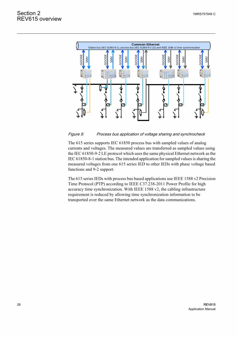
Figure 9: Process bus application of voltage sharing and synchrocheck
The 615 series supports IEC 61850 process bus with sampled values of analogcurrents and voltages. The measured values are transferred as sampled values usingthe IEC 61850-9-2 LE protocol which uses the same physical Ethernet network as theIEC 61850-8-1 station bus. The intended application for sampled values is sharing themeasured voltages from one 615 series IED to other IEDs with phase voltage basedfunctions and 9-2 support.
The 615 series IEDs with process bus based applications use IEEE 1588 v2 PrecisionTime Protocol (PTP) according to IEEE C37.238-2011 Power Profile for highaccuracy time synchronization. With IEEE 1588 v2, the cabling infrastructurerequirement is reduced by allowing time synchronization information to betransported over the same Ethernet network as the data communications.
Section 2 1MRS757946 CREV615 overview
28 REV615Application Manual

IEC 61850
HSR
SMV
tra
ffic
Backup 1588
master clock
Managed HSR
Ethernet
switch
Primary
IEEE 1588 v2
master clock
Secondary
IEEE 1588 v2
master clock
(optional)
Managed HSR
Ethernet
switch
GUID-7C56BC1F-F1B2-4E74-AB8E-05001A88D53D V4 EN
Figure 10: Example network topology with process bus, redundancy and IEEE1588 v2 time synchronization
The process bus option is available for all 615 series IEDs equipped with phasevoltage inputs. Another requirement is a communication card with IEEE 1588 v2support (COM0031...COM0037). However, RED615 supports this option only withthe communication card variant having fiber optic station bus ports. See the IEC61850 engineering guide for detailed system requirements and configuration details.
2.7.4 Secure communication
The protection relay supports secure communication for WHMI and file transferprotocol. If the Secure Communication parameter is activated, protocols require TLSbased encryption method support from the clients. In this case WHMI must beconnected from a Web browser using the HTTPS protocol and in case of file transferthe client must use FTPS.
1MRS757946 C Section 2REV615 overview
REV615 29Application Manual

30

Section 3 REV615 standard configurations
3.1 Standard configurations
REV615 is available in two alternative standard configurations. The standard signalconfiguration can be altered by means of the signal matrix or the graphical applicationfunctionality of the Protection and Control IED Manager PCM600. Further, theapplication configuration functionality of PCM600 supports the creation of multi-layer logic functions using various logical elements, including timers and flip-flops.By combining protection functions with logic function blocks, the relay configurationcan be adapted to user-specific application requirements.
The relay is delivered from the factory with default connections described in thefunctional diagrams for binary inputs, binary outputs, function-to-functionconnections and alarm LEDs. Some of the supported functions in REV615 must beadded with the Application Configuration tool to be available in the Signal Matrix tooland in the relay. The positive measuring direction of directional protection functionsis towards the outgoing feeder.
Table 9: Standard configurations
Description Std. conf.Capacitor bank overload and unbalance protection, non-directional overcurrent andearth-fault protection and circuit-breaker condition monitoring
A
Capacitor bank overload and unbalance protection, non-directional overcurrent anddirectional earth-fault protection, voltage and frequency based protection andmeasurements, and circuit-breaker condition monitoring
B
Table 10: Supported functions
Function IEC 61850 A BProtectionThree-phase non-directional overcurrent protection, low stage PHLPTOC 1 1Three-phase non-directional overcurrent protection, high stage PHHPTOC 2 2Three-phase non-directional overcurrent protection, instantaneous stage PHIPTOC 1 1Non-directional earth-fault protection, low stage EFLPTOC 2 Non-directional earth-fault protection, high stage EFHPTOC 1 1Non-directional earth-fault protection, instantaneous stage EFIPTOC 1 Directional earth-fault protection, low stage DEFLPDEF 2Directional earth-fault protection, high stage DEFHPDEF 1Transient/intermittent earth-fault protection INTRPTEF 1 1)
Negative-sequence overcurrent protection NSPTOC 2 2Residual overvoltage protection ROVPTOV 1
22)
Three-phase undervoltage protection PHPTUV 2Three-phase overvoltage protection PHPTOV 2
Table continues on next page
1MRS757946 C Section 3REV615 standard configurations
REV615 31Application Manual

Function IEC 61850 A BPositive-sequence undervoltage protection PSPTUV 1Negative-sequence overvoltage protection NSPTOV 1Three-phase thermal overload protection, two time constants T2PTTR 1 1Circuit breaker failure protection CCBRBRF 1 1Master trip TRPPTRC 2
(3) 3)2(3) 3)
Arc protection ARCSARC (3) (3)Multipurpose protection MAPGAPC 18 18Three-phase overload protection for shunt capacitor banks COLPTOC 1 1Current unbalance protection for shunt capacitor banks CUBPTOC 1 4) 1 4)
Three-phase current unbalance protection for shunt capacitor banks HCUBPTOC 1 4) 1 4)
Shunt capacitor bank switching resonance protection, current based SRCPTOC 1 1Power qualityCurrent total demand distortion CMHAI (1) 5) (1) 6)
Voltage total harmonic distortion VMHAI (1) 6)
Voltage variation PHQVVR (1) 6)
Voltage unbalance VSQVUB (1) 6)
ControlCircuit-breaker control CBXCBR 1 1Disconnector control DCXSWI 2 2Earthing switch control ESXSWI 1 1Disconnector position indication DCSXSWI 3 3Earthing switch indication ESSXSWI 2 2Condition monitoring and supervisionCircuit-breaker condition monitoring SSCBR 1 1Trip circuit supervision TCSSCBR 2 2Current circuit supervision CCSPVC 1 1Fuse failure supervision SEQSPVC 1Runtime counter for machines and devices MDSOPT 1 1MeasurementDisturbance recorder RDRE 1 1Load profile record LDPRLRC 1 1Fault record FLTRFRC 1 1Three-phase current measurement CMMXU 1 1Sequence current measurement CSMSQI 1 1Residual current measurement RESCMMXU 1 1Three-phase voltage measurement VMMXU 1Residual voltage measurement RESVMMXU 2Sequence voltage measurement VSMSQI 1Three-phase power and energy measurement PEMMXU 1RTD/mA measurement XRGGIO130 (1) (1)Frequency measurement FMMXU 1
IEC 61850-9-2 LE sampled value sending 7)8) SMVSENDER (1)
IEC 61850-9-2 LE sampled value receiving (voltage sharing) 7)8) SMVRCV (1)
OtherMinimum pulse timer (2 pcs) TPGAPC 4 4Minimum pulse timer (2 pcs, second resolution) TPSGAPC 1 1Minimum pulse timer (2 pcs, minute resolution) TPMGAPC 1 1Pulse timer (8 pcs) PTGAPC 2 2Time delay off (8 pcs) TOFGAPC 4 4Time delay on (8 pcs) TONGAPC 4 4Set-reset (8 pcs) SRGAPC 4 4
Table continues on next page
Section 3 1MRS757946 CREV615 standard configurations
32 REV615Application Manual

Function IEC 61850 A BMove (8 pcs) MVGAPC 2 2Generic control point (16 pcs) SPCGAPC 2 2Analog value scaling (4 pcs) SCA4GAPC 4 4Integer value move (4 pcs) MVI4GAPC 1 11, 2, ... = Number of included instances. The instances of a protection function represent the number of identical protection function blocks available in thestandard configuration.() = optional
1) "Io measured" is always used.2) "Uob measured" is always used.3) Master trip is included and connected to the corresponding HSO in the configuration only when the BIO0007 module is used. If additionally
the ARC option is selected, ARCSARC is connected to the corresponding master trip input in the configuration.4) The Iunb measurement values are taken from this block and put in the Measurent view.5) Power quality option includes only current total demand distortion.6) Power quality option includes current total demand distortion, voltage total harmonic distortion, voltage variation and voltage unbalance.7) Available only with IEC 61850-9-28) Available only with COM0031-0037
3.1.1 Addition of control functions for primary devices and the useof binary inputs and outputs
If extra control functions intended for controllable primary devices are added to theconfiguration, additional binary inputs and/or outputs are needed to complement thestandard configuration.
If the number of inputs and/or outputs in a standard configuration is not sufficient, itis possible either to modify the chosen IED standard configuration in order to releasesome binary inputs or binary outputs which have originally been configured for otherpurposes, or to integrate an external input/output module, for example RIO600, to theIED.
The external I/O module’s binary inputs and outputs can be used for the less time-critical binary signals of the application. The integration enables releasing someinitially reserved binary inputs and outputs of the IED’s standard configuration.
The suitability of the IED’s binary outputs which have been selected for primarydevice control should be carefully verified, for example make and carry and breakingcapacity. If the requirements for the primary device control circuit are not met, usingexternal auxiliary relays should be considered.
1MRS757946 C Section 3REV615 standard configurations
REV615 33Application Manual

3.2 Connection diagrams
REV615
X13Light sensor input 1 1)
X14Light sensor input 2 1)
X15Light sensor input 3 1)
1) Optional2) The IED features an automatic short-circuit mechanism in the CT connector when plug-in unit is detached3) BIO0005 Module (8BI+4BO) Alternative Module BIO0007 (8BI+3HSO)4) BIO0006 Module (6BI+3BO) Alternative Module RTD0001 (6RTD+2mA)
16
17
1918
X100
67
89
10
111213
15
14
2
1
3
45
22
212324
SO2
TCS2
PO4
SO1
TCS1
PO3
PO2
PO1
IRF
+
-Uaux
20
X110
34
56
7
89
10BI 6
BI 5
BI 4
BI 3
BI 2
BI 8
BI 712
13
11
BI 112
X110
16
14
15
19
17
18
22
20
21
SO3
SO2
SO1
23SO4
24
2)
X120
1
23
45
67
89
1011
1213
14
IL1unb1/5A
N
IL2unb
IL1
IL2
IL3
Io
1/5A
N1/5A
N1/5A
N1/5A
N1/5A
N1/5A
N
IL3unb
3)
3)
X130
12
3
45
6BI 4
BI 3
BI 2
BI 1
BI 6
BI 58
9
7
X130
12
10
11
15
13
14
18
16
17
SO3
SO2
SO1
4)
4)
L1L2L3
S1
S2
P1
P2
PositiveCurrentDirection
S1
S2
P1
P2
GUID-6E21CF35-D1AC-484F-99C0-830FA9F70960 V1 EN
Figure 11: Connection diagram for the A configuration
Section 3 1MRS757946 CREV615 standard configurations
34 REV615Application Manual

REV615
X13Light sensor input 1 1)
X14Light sensor input 2 1)
X15Light sensor input 3 1)
1) Optional2) The IED features an automatic short-circuit mechanism in the CT connector when plug-in unit is detached3) BIO0005 Module (8BI+4BO) Alternative Module BIO0007 (8BI+3HSO)4) AIM0006 Module (5U+4BI) Alternative Module AIM0003 (5U+2RTD+1mA)
16
17
1918
X100
67
89
10
111213
15
14
2
1
3
45
22
212324
SO2
TCS2
PO4
SO1
TCS1
PO3
PO2
PO1
IRF
+
-Uaux
20
X110
34
56
7
89
10BI 6
BI 5
BI 4
BI 3
BI 2
BI 8
BI 712
13
11
BI 112
X110
16
14
15
19
17
18
22
20
21
SO3
SO2
SO1
23SO4
24
2)
X120
1
23
45
67
89
1011
1213
14
IL1unb1/5A
N
IL2unb
IL1
IL2
IL3
Io
1/5A
N1/5A
N1/5A
N1/5A
N1/5A
N1/5A
N
IL3unb
3)
3)
X13012
34
56
BI 4
BI 3
BI 2
BI 1
87
9101112
UoB
1314
U1
1516
U2
1718
U3
UoN
N
N
N
60 -
N
210V
60 -210V
60 -210V
60 -210V
60 -210V
4)
L1L2L3
S1
S2
P1
P2
PositiveCurrentDirection
S1
S2
P1
P2
da dn
a
nN
A
GUID-2750EADB-83D4-4222-A759-12432FD8D118 V1 EN
Figure 12: Connection diagram for the B configuration
3.3 Standard configuration A
3.3.1 Applications
The standard configuration offers three-phase overload protection, unbalanceprotection with compensation for natural unbalance and switching resonanceprotection for capacitor banks. An integrated undercurrent function in the overload
1MRS757946 C Section 3REV615 standard configurations
REV615 35Application Manual

protection function block detects the disconnection of a capacitor bank and inhibitsthe closing of the circuit breaker as long as the capacitor bank is still partiallydischarged. A three-phase thermal overload protection is available and can be used forthe thermal protection of the reactors and resistors in the harmonic filter circuits.
The standard configuration is pre-configured for H-bridge connected capacitor banks.A three-phase current unbalance protection is used for unbalance protection.
The IED with a standard configuration is delivered from the factory with defaultsettings and parameters. The end user flexibility for incoming, outgoing and internalsignal designation within the IED enables this configuration to be further adapted todifferent primary circuit layouts and the related functionality needs by modifying theinternal functionality using PCM600.
Section 3 1MRS757946 CREV615 standard configurations
36 REV615Application Manual

3.3.2 Functions
3I
CONDITION MONITORING AND SUPERVISION
ORAND
CONTROL AND INDICATION 1) MEASUREMENT
CAPACITOR BANK PROTECTION AND CONTROL RELAY STANDARD CONFIGURATION
PROTECTION LOCAL HMI
Object Ctrl 2) Ind 3)
CB
DC
ES1) Check availability of binary inputs/outputs
from technical documentation2) Control and indication function for
primary object3) Status indication function for primary object
RL
ClearESCI
O
Configuration ASystemHMITimeAuthorization
RL
ClearESCI
O
U12 0. 0 kVP 0.00 kWQ 0.00 kVAr
IL2 0 A
A
REMARKS
Optionalfunction
No. ofinstances
Alternative function to be defined when ordering
OR
Io/Uo
Calculatedvalue
3×
REV615 A
COMMUNICATION
Protocols: IEC 61850-8-1 Modbus®
IEC 60870-5-103 DNP3Interfaces: Ethernet: TX (RJ45), FX (LC) Serial: Serial glass fiber (ST), RS-485, RS-232Redundant protocols: HSR PRP RSTP
- I, Io- Limit value supervision- Load profile record- RTD/mA measurement (optional)- Symmetrical components
7
-
Analog interface types 1)
Current transformer
Voltage transformer1) Conventional transformer inputs
ALSO AVAILABLE
- Disturbance and fault recorders- Event log and recorded data- High-Speed Output module (optional) - Local/Remote push button on LHMI- Self-supervision- Time synchronization: IEEE 1588 v2,
SNTP, IRIG-B- User management- Web HMI 2×
I2>46
3I>>>50P/51P
3×ARC
50L/50NL
Master TripLockout relay
94/86
3I>/Io>BF51BF/51NBF
PQM3IPQM3I
2×TCSTCM
MCS 3IMCS 3I
CBCMCBCM
OPTSOPTM
18×MAPMAP
6xRTD2xmA
3I>51P-1
2×3I>>
51P-2TD>55TD
3I>3I<51C
Io>>51N-2
Io>>>50N/51N
2×Io>
51N-1
3dI>C51NC-2
dI>C51NC-1
3Ith>T/G/C49T/G/C
Io
Io
3Iunb
Io
1 -
2 3
1 2
Master TripLockout relay
94/86
3×2×
3×
GUID-DFC320F5-AD45-4D28-8632-C3FB2CFDCB06 V3 EN
Figure 13: Functionality overview for standard configuration A
3.3.2.1 Default I/O connections
Connector pins for each input and output are presented in the IED physicalconnections section.
1MRS757946 C Section 3REV615 standard configurations
REV615 37Application Manual

Table 11: Default connections for binary inputs
Binary input DescriptionX110-BI1 Circuit breaker low gas pressure indication
X110-BI2 Circuit breaker spring charged indication
X110-BI3 Circuit breaker open indication
X110-BI4 Circuit breaker closed indication
X110-BI5 Circuit breaker truck out (test position) indication
X110-BI6 Circuit breaker truck in (service position) indication
X110-BI7 Earth switch open indication
X110-BI8 Earth switch closed indication
Table 12: Default connections for binary outputs
Binary output DescriptionX100-PO1 Close circuit breaker
X100-PO2 Breaker failure backup trip to upstream breaker
X100-SO1 General start indication
X100-SO2 General operate indication
X100-PO3 Open circuit breaker/trip coil 1
X100-PO4 Capacitor bank reconnection enable
X110-SO1 Overcurrent operate alarm
X110-SO2 Earth-fault operate alarm
X110-SO3 Capacitor unbalance operate alarm
X110-SO4 Other capacitor operate alarm
X110-HSO1 Arc protection instance 1 operate activated
X110-HSO2 Arc protection instance 2 operate activated
X110-HSO3 Arc protection instance 3 operate activated
Table 13: Default connections for LEDs
LED Description1 Overcurrent protection operated
2 Earth-fault protection operated
3 Capacitor or thermal overload protection operated
4 Capacitor overload alarm
5 Capacitor unbalance or negative phase sequence protection operator
6 -
7 Undercurrent or resonance protection operated
8 Circuit breaker failure protection operated
9 Disturbance recorder triggered
10 Supervision alarms
11 Arc-fault detected
Section 3 1MRS757946 CREV615 standard configurations
38 REV615Application Manual

3.3.2.2 Default disturbance recorder settings
Table 14: Default disturbance recorder analog channels
Channel Description1 IL1
2 IL2
3 IL3
4 IL1unb
5 IL2unb
6 IL3unb
7 Io
8 -
9 -
10 -
11 -
12 -
Table 15: Default disturbance recorder binary channels
Channel ID text Level trigger mode1 PHIPTOC1 - start Positive or Rising
2 PHHPTOC1 - start Positive or Rising
3 PHHPTOC2 - start Positive or Rising
4 PHLPTOC1 - start Positive or Rising
5 EFHPTOC1 - start Positive or Rising
6 EFIPTOC1 - start Positive or Rising
7 EFLPTOC1 - start Positive or Rising
8 EFLPTOC2 - start Positive or Rising
9 NSPTOC1 - start Positive or Rising
10 NSPTOC2 - start Positive or Rising
11 T2PTTR1 - start Positive or Rising
12 COLPTOC1 - start ovload Positive or Rising
13 COLPTOC1 - start un I Positive or Rising
14 HCUBPTOC1 - start Positive or Rising
15 PHIPTOC1 - operate Level trigger off
PHHPTOC1 - operate
PHHPTOC2 - operate
PHLPTOC1 - operate
Table continues on next page
1MRS757946 C Section 3REV615 standard configurations
REV615 39Application Manual

Channel ID text Level trigger mode16 EFLPTOC1 - operate Level trigger off
EFLPTOC2 - operate
EFHPTOC1 - operate
EFIPTOC1 - operate
17 NSPTOC1 - operate Level trigger off
NSPTOC2 - operate
18 T2PTTR1 - operate Level trigger off
19 COLPTOC1 - operate ovload Level trigger off
20 COLPTOC1 - operate un I Level trigger off
21 HCUBPTOC1 - operate Level trigger off
22 T2PTTR1 - alarm Level trigger off
23 SRCPTOC1 - alarm Positive or Rising
24 COLPTOC1 - alarm Level trigger off
25 SRCPTOC1 - operate Level trigger off
26 CCBRBRF1 - trret Level trigger off
27 CCBRBRF1 - trbu Level trigger off
28 CCSPVC1 - fail Level trigger off
29 X110BI4 - CB closed Level trigger off
30 X110BI3 - CB opened Level trigger off
31 ARCSARC1 - ARC flt det Level trigger off
ARCSARC2 - ARC flt det
ARCSARC3 - ARC flt det
32 ARCSARC1 - operate Positive or Rising
33 ARCSARC2 - operate Positive or Rising
34 ARCSARC3 - operate Positive or Rising
3.3.3 Functional diagrams
The functional diagrams describe the default input, output, alarm LED and function-to-function connections. The default connections can be viewed and changed withPCM600 according to the application requirements.
The analog channels have fixed connections to the different function blocks inside theIED’s standard configuration. However, the 12 analog channels available for thedisturbance recorder function are freely selectable as a part of the disturbancerecorder’s parameter settings.
The capacitor phase currents as well as capacitor unbalance current to the IED are fedfrom a current transformer. The residual current to the IED is fed either fromresidually connected current transformers, an external core balance CT, neutral CT orinternally calculated.
Section 3 1MRS757946 CREV615 standard configurations
40 REV615Application Manual

The IED offers six different settings group which can be set based on the individualneeds. Each group can be activated or deactivated using the setting group settingsavailable in the IED.
Depending on the communication protocol the required function block needs to beinstantiated in the configuration.
3.3.3.1 Functional diagrams for protection
The functional diagrams describe the IEDs protection functionality in detail andaccording to the factory set default connections.
Four non-directional overcurrent stages are offered for capacitor overcurrent andshort-circuit protection.
PHIPTOC1BLOCKENA_MULT
OPERATESTART
PHLPTOC1BLOCKENA_MULT
OPERATESTART
PHHPTOC1BLOCKENA_MULT
OPERATESTART
PHHPTOC2BLOCKENA_MULT
OPERATESTART
OR6B1B2B3B4B5B6
O
PHLPTOC1_OPERATE
PHLPTOC1_OPERATE
PHHPTOC1_OPERATE
PHHPTOC1_OPERATE
PHHPTOC2_OPERATE
PHHPTOC2_OPERATE
PHIPTOC1_OPERATE
PHIPTOC1_OPERATE
PHLPTOC1_START
PHHPTOC1_START
PHHPTOC2_START
PHIPTOC1_START
OC_OPERATE
GUID-F44AEFA0-6C24-41B7-B73B-AABC9E9A5AEE V1 EN
Figure 14: Overcurrent protection functions
Two negative-sequence overcurrent protection stages NSPTOC1 and NSPTOC2 areprovided for phase unbalance protection. These functions are used to protect thecapacitor against unbalance conditions. The negative-sequence overcurrentprotection functions are blocked in case of detection of a failure in secondary circuitof the current transformer.
1MRS757946 C Section 3REV615 standard configurations
REV615 41Application Manual

NSPTOC1BLOCKENA_MULT
OPERATESTART
NSPTOC2BLOCKENA_MULT
OPERATESTART
ORB1B2
O
NSPTOC1_OPERATE
NSPTOC1_OPERATE
NSPTOC2_OPERATE
NSPTOC2_OPERATE
NSPTOC1_START
NSPTOC2_START
CCSPVC1_FAIL
CCSPVC1_FAIL
NSPTOC_OPERATE
GUID-17616E9D-2491-400F-922F-CA3C44B1835B V2 EN
Figure 15: Negative-sequence overcurrent protection function
Four stages are provided for non-directional earth-fault protection.
EFHPTOC1BLOCKENA_MULT
OPERATESTART
EFIPTOC1BLOCKENA_MULT
OPERATESTART
EFLPTOC1BLOCKENA_MULT
OPERATESTART
EFLPTOC2BLOCKENA_MULT
OPERATESTART
OR6B1B2B3B4B5B6
O
EFHPTOC1_OPERATE
EFHPTOC1_OPERATE
EFIPTOC1_OPERATE
EFIPTOC1_OPERATE
EFLPTOC1_OPERATE
EFLPTOC1_OPERATE
EFLPTOC2_OPERATE
EFLPTOC2_OPERATE
EFLPTOC1_START
EFLPTOC2_START
EFHPTOC1_START
EFIPTOC1_START
EF_OPERATE
GUID-B0744352-B69D-4A7A-ADA4-DB96C09ABD2B V1 EN
Figure 16: Earth-fault protection functions
Section 3 1MRS757946 CREV615 standard configurations
42 REV615Application Manual

The three-phase thermal overload protection T2PTTR1 with two time constantsdetects overload under varying load conditions. The BLK_CLOSE output of thefunction is used to block the closing operation of circuit breaker.
T2PTTR1BLOCKTEMP_AMB
OPERATESTARTALARM
BLK_CLOSE T2PTTR1_BLK_CLOSE
T2PTTR1_OPERATET2PTTR1_STARTT2PTTR1_ALARM
GUID-DD6AEBAD-E5BA-4D62-9733-394B195E4F1B V1 EN
Figure 17: Thermal overcurrent protection function
The circuit breaker failure protection CCBRBRF1 is initiated via the START input bya number of different protection functions available in the IED. The circuit breakerfailure protection function offers different operating modes associated with the circuitbreaker position and the measured phase and residual currents.
The circuit breaker failure protection function has two operating outputs: TRRET andTRBU. The TRRET operate output is used for retripping its own breaker throughTRPPTRC2_TRIP. The TRBU output is used to give a backup trip to the breakerfeeding upstream. For this purpose, the TRBU operate output signal is connected to thebinary output X100:PO2.
CCBRBRF1BLOCKSTARTPOSCLOSECB_FAULT
CB_FAULT_ALTRBU
TRRET
OR6B1B2B3B4B5B6
O
OR6B1B2B3B4B5B6
O
OR6B1B2B3B4B5B6
O
OR6B1B2B3B4B5B6
O
CCBRBRF1_TRBU
X110_BI4_CB_CLOSED
EFHPTOC1_OPERATE
EFIPTOC1_OPERATE
NSPTOC1_OPERATENSPTOC2_OPERATE
T2PTTR1_OPERATE
COLPTOC1_OPR_OVLODCOLPTOC1_OPR_UN_I
HCUBPTOC1_OPERATEARCSARC1_OPERATEARCSARC2_OPERATEARCSARC3_OPERATE
PHLPTOC1_OPERATE
PHHPTOC1_OPERATEPHHPTOC2_OPERATE
PHIPTOC1_OPERATE
EFLPTOC1_OPERATEEFLPTOC2_OPERATE
SRCPTOC1_OPERATE
CCBRBRF1_TRRET
GUID-633258B3-D89D-418F-ABFA-B27C2DD77778 V1 EN
Figure 18: Circuit breaker failure protection function
Three arc protection stages ARCSARC1...3 are included as an optional function. Thearc protection offers individual function blocks for three arc sensors that can beconnected to the IED. Each arc protection function block has two different operationmodes, that is, with or without the phase and residual current check.
The operate signals from ARCSARC1...3 are connected to both trip logic TRPPTRC1and TRPPTRC2. If the IED has been ordered with high speed binary outputs, theindividual operate signals from ARCSARC1...3 are connected to dedicated trip logicTRPPTRC3...5. The outputs of TRPPTRC3...5 are available at high speed outputsX110:HSO1, X110:HSO2 and X110:HSO3.
1MRS757946 C Section 3REV615 standard configurations
REV615 43Application Manual

ARCSARC1BLOCKREM_FLT_ARCOPR_MODE
OPERATEARC_FLT_DET
ARCSARC2BLOCKREM_FLT_ARCOPR_MODE
OPERATEARC_FLT_DET
ARCSARC3BLOCKREM_FLT_ARCOPR_MODE
OPERATEARC_FLT_DET
OR6B1B2B3B4B5B6
O
ARCSARC1_OPERATE
ARCSARC1_OPERATE
ARCSARC2_OPERATE
ARCSARC2_OPERATE
ARCSARC3_OPERATE
ARCSARC3_OPERATE
ARCSARC1_ARC_FLT_DET
ARCSARC2_ARC_FLT_DET
ARCSARC3_ARC_FLT_DET
ARCSARC_OPERATE
GUID-AD0475AD-B69E-4EAE-AAAE-470275749B45 V1 EN
TRPPTRC3BLOCKOPERATERST_LKOUT
TRIPCL_LKOUT
TRPPTRC4BLOCKOPERATERST_LKOUT
TRIPCL_LKOUT
TRPPTRC5BLOCKOPERATERST_LKOUT
TRIPCL_LKOUT
TRPPTRC3_TRIP
TRPPTRC4_TRIP
TRPPTRC5_TRIP
ARCSARC1_OPERATE
ARCSARC2_OPERATE
ARCSARC3_OPERATE
GUID-6120D810-63F0-4D7B-BA6F-DD519D6343AC V1 EN
Figure 19: Arc protection with dedicated HSO
Three-phase overload protection for shunt capacitor banks COLPTOC1 providesprotection against overloads caused due to harmonic currents and overvoltage in shuntcapacitor banks. The BLK_CLOSE output of the function is used to block the closingoperation of circuit breaker.
Section 3 1MRS757946 CREV615 standard configurations
44 REV615Application Manual
COLPTOC1BLOCKCB_CLOSED
OPR_OVLODOPR_UN_I
ST_OVLODST_UN_I
ALARMBLK_CLOSE
X110_BI4_CB_CLOSED
COLPTOC1_BLK_CLOSE
COLPTOC1_OPR_OVLODCOLPTOC1_OPR_UN_ICOLPTOC1_ST_OVLODCOLPTOC1_ST_UN_ICOLPTOC1_ALARM
GUID-13EE20DE-CBD6-475C-A4A8-2B13760055DC V1 EN
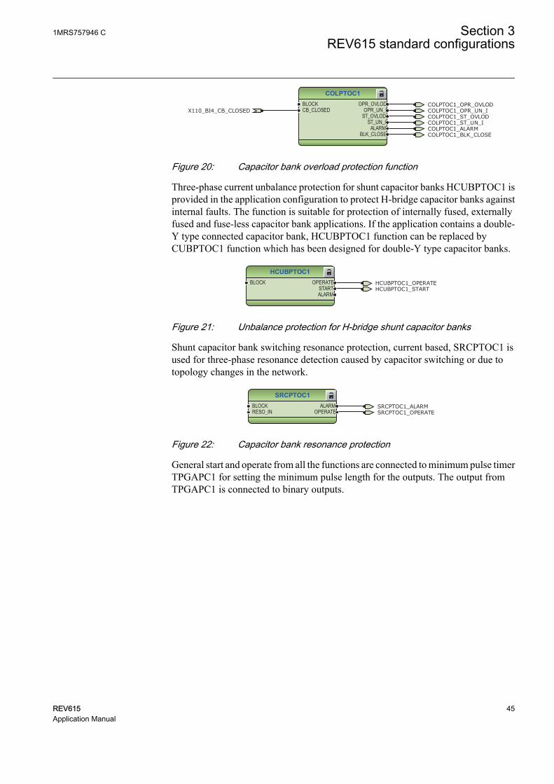
Figure 20: Capacitor bank overload protection function
Three-phase current unbalance protection for shunt capacitor banks HCUBPTOC1 isprovided in the application configuration to protect H-bridge capacitor banks againstinternal faults. The function is suitable for protection of internally fused, externallyfused and fuse-less capacitor bank applications. If the application contains a double-Y type connected capacitor bank, HCUBPTOC1 function can be replaced byCUBPTOC1 function which has been designed for double-Y type capacitor banks.
HCUBPTOC1BLOCK OPERATE
STARTALARM
HCUBPTOC1_OPERATEHCUBPTOC1_START
GUID-12E4FC9C-4F80-475C-98F0-BCEC1F5914E5 V1 EN
Figure 21: Unbalance protection for H-bridge shunt capacitor banks
Shunt capacitor bank switching resonance protection, current based, SRCPTOC1 isused for three-phase resonance detection caused by capacitor switching or due totopology changes in the network.
SRCPTOC1BLOCKRESO_IN
ALARMOPERATE SRCPTOC1_OPERATE
SRCPTOC1_ALARM
GUID-C417AE30-0923-45CA-910C-39836780A12E V
Figure 22: Capacitor bank resonance protection
General start and operate from all the functions are connected to minimum pulse timerTPGAPC1 for setting the minimum pulse length for the outputs. The output fromTPGAPC1 is connected to binary outputs.
1MRS757946 C Section 3REV615 standard configurations
REV615 45Application Manual

TPGAPC1IN1IN2
OUT1OUT2
OR6B1B2B3B4B5B6
O
OR6B1B2B3B4B5B6
O
OR6B1B2B3B4B5B6
O
OR6B1B2B3B4B5B6
O
OR6B1B2B3B4B5B6
O
OR6B1B2B3B4B5B6
O
OR6B1B2B3B4B5B6
O
OR6B1B2B3B4B5B6
O
GENERATE_START_PULSEGENERATE_OPERATE_PULSE
EFHPTOC1_OPERATEEFIPTOC1_OPERATENSPTOC1_OPERATENSPTOC2_OPERATET2PTTR1_OPERATE
COLPTOC1_OPR_OVLOD
COLPTOC1_OPR_UN_IHCUBPTOC1_OPERATE
ARCSARC1_OPERATEARCSARC2_OPERATEARCSARC3_OPERATE
PHLPTOC1_OPERATEPHHPTOC1_OPERATEPHHPTOC2_OPERATEPHIPTOC1_OPERATEEFLPTOC1_OPERATEEFLPTOC2_OPERATE
PHLPTOC1_STARTPHHPTOC1_STARTPHHPTOC2_STARTPHIPTOC1_STARTEFLPTOC1_STARTEFLPTOC2_START
EFHPTOC1_STARTEFIPTOC1_STARTNSPTOC1_STARTNSPTOC2_STARTT2PTTR1_START
COLPTOC1_ST_OVLOD
COLPTOC1_ST_UN_IHCUBPTOC1_START
GUID-F644FD19-1CEB-46B9-92A5-BD30DAFDCD25 V1 EN
Figure 23: General start and operate signals
The operate signals from the protection functions are connected to two trip logics:TRPPTRC1 and TRPPTRC2. The output of TRPPTRC1 is available at binary outputX100:PO3. The trip logic functions are provided with a lockout and latching function,event generation and the trip signal duration setting. If the lockout operation mode isselected, binary input can been assigned to RST_LKOUT input of both the trip logicto enable external reset with a push button.
Three other trip logics TRPPTRC3...5 are also available if the IED is ordered withhigh speed binary outputs options.
Section 3 1MRS757946 CREV615 standard configurations
46 REV615Application Manual

TRPPTRC1BLOCKOPERATERST_LKOUT
TRIPCL_LKOUT
OR6B1B2B3B4B5B6
O
OR6B1B2B3B4B5B6
O
OR6B1B2B3B4B5B6
O
OR6B1B2B3B4B5B6
OTRPPTRC1_TRIP
EFHPTOC1_OPERATEEFIPTOC1_OPERATENSPTOC1_OPERATENSPTOC2_OPERATET2PTTR1_OPERATE
COLPTOC1_OPR_OVLOD
COLPTOC1_OPR_UN_IHCUBPTOC1_OPERATE
ARCSARC1_OPERATEARCSARC2_OPERATEARCSARC3_OPERATE
PHLPTOC1_OPERATEPHHPTOC1_OPERATEPHHPTOC2_OPERATEPHIPTOC1_OPERATEEFLPTOC1_OPERATEEFLPTOC2_OPERATE
SRCPTOC1_OPERATE
GUID-D903E6A4-F42A-4BF3-BCD2-0C38F4301B53 V1 EN
Figure 24: Trip logic TRPPTRC1
OR6B1B2B3B4B5B6
O
TRPPTRC2BLOCKOPERATERST_LKOUT
TRIPCL_LKOUT
OR6B1B2B3B4B5B6
O
OR6B1B2B3B4B5B6
O
OR6B1B2B3B4B5B6
OTRPPTRC2_TRIP
EFHPTOC1_OPERATEEFIPTOC1_OPERATENSPTOC1_OPERATENSPTOC2_OPERATET2PTTR1_OPERATE
COLPTOC1_OPR_OVLOD
COLPTOC1_OPR_UN_IHCUBPTOC1_OPERATE
ARCSARC1_OPERATEARCSARC2_OPERATEARCSARC3_OPERATE
PHLPTOC1_OPERATEPHHPTOC1_OPERATEPHHPTOC2_OPERATEPHIPTOC1_OPERATEEFLPTOC1_OPERATEEFLPTOC2_OPERATE
SRCPTOC1_OPERATE
CCBRBRF1_TRRET
GUID-06C6D0C6-F6FB-4B9C-971C-CFDD9C2C914B V1 EN
Figure 25: Trip logic TRPPTRC2
3.3.3.2 Functional diagrams for disturbance recorder
The START and the OPERATE outputs from the protection stages are routed to triggerthe disturbance recorder or, alternatively, only to be recorded by the disturbancerecorder depending on the parameter settings. Additionally, the selected signals fromdifferent functions and the few binary inputs are also connected to the disturbancerecorder.
1MRS757946 C Section 3REV615 standard configurations
REV615 47Application Manual

RDRE1C1C2C3C4C5C6C7C8C9C10C11C12C13C14C15C16C17C18C19C20C21C22C23C24C25C26C27C28C29C30C31C32C33C34C35C36C37C38C39C40C41C42C43C44C45C46C47C48C49C50C51C52C53C54C55C56C57C58C59C60C61C62C63C64
TRIGGEREDOR6
B1B2B3B4B5B6
O
OR6B1B2B3B4B5B6
O
ORB1B2
O
OR6B1B2B3B4B5B6
O
CCBRBRF1_TRBU
X110_BI3_CB_OPENEDX110_BI4_CB_CLOSED
EFHPTOC1_OPERATE
EFIPTOC1_OPERATE
NSPTOC1_OPERATENSPTOC2_OPERATE
T2PTTR1_OPERATECOLPTOC1_OPR_OVLOD
COLPTOC1_OPR_UN_IHCUBPTOC1_OPERATE
ARCSARC1_OPERATEARCSARC2_OPERATEARCSARC3_OPERATE
PHLPTOC1_OPERATE
PHHPTOC1_OPERATEPHHPTOC2_OPERATE
PHIPTOC1_OPERATE
EFLPTOC1_OPERATEEFLPTOC2_OPERATE
SRCPTOC1_OPERATECCBRBRF1_TRRET
PHLPTOC1_START
PHHPTOC1_STARTPHHPTOC2_START
PHIPTOC1_START
EFLPTOC1_STARTEFLPTOC2_START
EFHPTOC1_STARTEFIPTOC1_START
NSPTOC1_STARTNSPTOC2_STARTT2PTTR1_START
COLPTOC1_ST_OVLODCOLPTOC1_ST_UN_IHCUBPTOC1_START
CCSPVC1_FAIL
ARCSARC1_ARC_FLT_DETARCSARC2_ARC_FLT_DETARCSARC3_ARC_FLT_DET
T2PTTR1_ALARMSRCPTOC1_ALARMCOLPTOC1_ALARM
DISTURB_RECORD_TRIGGERED
GUID-6C2585FD-C0EF-4ED4-8266-85D4E1A9C21A V2 EN
Figure 26: Disturbance recorder
3.3.3.3 Functional diagrams for condition monitoring
CCSPVC1 detects failures in the current measuring circuits. When a failure isdetected, it is used to block the current protection functions that measure thecalculated sequence component currents or residual current to avoid unnecessaryoperation.
CCSPVC1BLOCK FAIL
ALARMCCSPVC1_FAILCCSPVC1_ALARM
GUID-1F1C3820-1BE7-466A-9635-9D1BEE469DA6 V2 EN
Figure 27: Current circuit supervision function
The circuit-breaker condition monitoring function SSCBR1 supervises the switchstatus based on the connected binary input information and the measured currentlevels. SSCBR1 introduces various supervision methods.
Section 3 1MRS757946 CREV615 standard configurations
48 REV615Application Manual

SSCBR1BLOCKPOSOPENPOSCLOSEOPEN_CB_EXECLOSE_CB_EXEPRES_ALM_INPRES_LO_INSPR_CHR_STSPR_CHRRST_IPOWRST_CB_WEARRST_TRV_TRST_SPR_T
TRV_T_OP_ALMTRV_T_CL_ALMSPR_CHR_ALM
OPR_ALMOPR_LO
IPOW_ALMIPOW_LO
CB_LIFE_ALMMON_ALM
PRES_ALMPRES_LO
OPENPOSINVALIDPOSCLOSEPOS
CB_CLOSE_COMMANDCB_OPEN_COMMAND
X110_BI3_CB_OPENEDX110_BI4_CB_CLOSED
X110_BI2_CB_SPRING_CHARGED
X110_BI1_GAS_PRESSURE_ALARM
CB_SPRING_DISCHARGED
SSCBR1_TRV_T_OP_ALMSSCBR1_TRV_T_CL_ALMSSCBR1_SPR_CHR_ALMSSCBR1_OPR_ALMSSCBR1_OPR_LOSSCBR1_IPOW_ALMSSCBR1_IPOW_LOSSCBR1_CB_LIFE_ALMSSCBR1_MON_ALMSSCBR1_PRES_ALMSSCBR1_PRES_LO
GUID-42D5E911-3FB1-487D-AF85-9C80EFA0B65C V1 EN
Figure 28: Circuit-breaker condition monitoring function
ORB1B2
O
OR6B1B2B3B4B5B6
O
OR6B1B2B3B4B5B6
O
SSCBR1_TRV_T_OP_ALMSSCBR1_TRV_T_CL_ALMSSCBR1_SPR_CHR_ALM
SSCBR1_OPR_ALMSSCBR1_OPR_LO
SSCBR1_IPOW_ALM
SSCBR1_IPOW_LOSSCBR1_CB_LIFE_ALM
SSCBR1_MON_ALMSSCBR1_PRES_ALM
SSCBR1_PRES_LO
SSCBR1_ALARMS
GUID-A6334A2F-B17C-4689-A5BA-B2C6273ACBFA V1 EN
Figure 29: Logic for circuit breaker monitoring alarm
NOTIN OUTX110_BI2_CB_SPRING_CHARGED CB_SPRING_DISCHARGED
GUID-627752B9-D32B-4135-914C-71619713971D V1 EN
Figure 30: Logic for start of circuit breaker spring charging
Two separate trip circuit supervision functions are included: TCSSCBR1 for poweroutput X100:PO3 and TCSSCBR2 for power output X100:PO4. The functions areblocked by the master trip TRPPTRC1 and TRPPTRC2 and the circuit breaker opensignal.
It is assumed that there is no external resistor in the circuit breakertripping coil circuit connected in parallel with the circuit breakernormally open auxiliary contact.
Set the parameters for TCSSCBR1 properly.
1MRS757946 C Section 3REV615 standard configurations
REV615 49Application Manual

TCSSCBR1BLOCK ALARM
TCSSCBR2BLOCK ALARM
ORB1B2
O
TCSSCBR1_ALARM
TCSSCBR1_ALARM
TCSSCBR2_ALARM
TCSSCBR2_ALARM
TCSSCBR_BLOCKING
TCSSCBR_BLOCKING
TCSSCBR_ALARM
GUID-400C35B2-0D30-40F7-B62B-3021AA09875F V1 EN
Figure 31: Trip circuit supervision function
OR6B1B2B3B4B5B6
O
X110_BI3_CB_OPENED
TRPPTRC1_TRIPTRPPTRC2_TRIP
TCSSCBR_BLOCKING
GUID-2C52341D-A1CA-429B-8381-ACDBFDAE0558 V1 EN
Figure 32: Logic for blocking trip logic circuit supervision
3.3.3.4 Functional diagrams for control and interlocking
There are two types of disconnector and earthing switch function blocks.DCSXSWI1...3 and ESSXSWI1...2 are status only type, and DCXSWI1...2 andESXSWI1 are controllable type. By default, the status only blocks are connected instandard configuration. The disconnector (CB truck) and line side earthing switchstatus information are connected to DCSXSWI1 and ESSXSI1.
DCSXSWI1POSOPENPOSCLOSE
OPENPOSCLOSEPOS
OKPOS DCSXSWI1_OKPOS
X110_BI6_CB_TRUCK_IN_TESTX110_BI5_CB_TRUCK_IN_SERVICE
GUID-3C6C5D27-1FD1-4DFF-ADCF-940D1CEF7754 V1 EN
Figure 33: Disconnector 1 control logic
ESSXSWI1POSOPENPOSCLOSE
OPENPOSCLOSEPOS
OKPOS
ESSXSWI1_OPENPOSX110_BI7_ES1_OPENEDX110_BI8_ES1_CLOSED
GUID-A4C2DD66-9DDE-4228-80B5-CE7DA09D15E2 V1 EN
Figure 34: Earth-switch control logic
Section 3 1MRS757946 CREV615 standard configurations
50 REV615Application Manual

The circuit breaker closing is enabled when the ENA_CLOSE input is activated. Theinput can be activated using the configuration logic, which is a combination of thedisconnector or breaker truck and earth-switch position status, status of the trip logics,gas pressure alarm and circuit-breaker spring charging status.
The OKPOS output from DCSXSWI defines whether the disconnector or breakertruck is either open (in test position) or close (in service position). This output,together with the open earth-switch and non-active trip signals, activates the close-enable signal to the circuit-breaker control function block. The open operation forcircuit breaker is always enabled.
The SYNC_ITL_BYP input can be used, for example, to always enable the closing ofthe circuit breaker when the circuit breaker truck is in the test position, despite theinterlocking conditions being active when the circuit breaker truck is closed in serviceposition.
CBXCBR1POSOPENPOSCLOSEENA_OPENENA_CLOSEBLK_OPENBLK_CLOSEAU_OPENAU_CLOSETRIPSYNC_OKSYNC_ITL_BYP
SELECTEDEXE_OPEXE_CL
OP_REQCL_REQ
OPENPOSCLOSEPOS
OKPOSOPEN_ENAD
CLOSE_ENAD
TRUE
X110_BI3_CB_OPENEDX110_BI4_CB_CLOSED
CBXCBR1_ENA_CLOSECBXCBR1_EXE_CLCBXCBR1_EXE_OP
CBXCBR1_BLK_CLOSEFALSE
CBXCBR1_AU_OPENCBXCBR1_AU_CLOSE
GUID-36F27E21-4648-44E6-B1F0-69621F0AAB6C V2 EN
Figure 35: Circuit breaker control logic: Circuit breaker 1
Connect the additional signals required for the application for closingand opening of circuit breaker.
ORB1B2
O CB_CLOSE_COMMANDCBXCBR1_EXE_CL
GUID-B3C31E9E-9C06-4CB0-A5EF-FFAA8F560A2F V1 EN
Figure 36: Circuit breaker control logic: Signals for closing coil of circuit breaker
OR6B1B2B3B4B5B6
O CB_OPEN_COMMANDTRPPTRC1_TRIPCBXCBR1_EXE_OP
GUID-CA037F31-80A3-4AC2-8632-EA92C34F1474 V1 EN
Figure 37: Circuit breaker control logic: Signals for opening coil of circuit breaker
1MRS757946 C Section 3REV615 standard configurations
REV615 51Application Manual

AND6B1B2B3B4B5B6
O
NOTIN OUT
NOTIN OUT
NOTIN OUT
CBXCBR1_ENA_CLOSE
TRPPTRC1_TRIP
DCSXSWI1_OKPOSX110_BI2_CB_SPRING_CHARGED
X110_BI1_GAS_PRESSURE_ALARM
ESSXSWI1_OPENPOS
TRPPTRC2_TRIP
GUID-A0980B62-CA07-4610-890D-973D87E22FBF V1 EN
Figure 38: Circuit breaker close enable logic
OR6B1B2B3B4B5B6
O CBXCBR1_BLK_CLOSET2PTTR1_BLK_CLOSE
COLPTOC1_BLK_CLOSE
GUID-38693D6F-1F5A-48CF-9599-BDC4B4966AA1 V1 EN
Figure 39: Circuit breaker close blocking logic
The configuration includes the logic for generating circuit breaker external closingand opening command with the IED in local or remote mode.
Check the logic for the external circuit breaker closing command andmodify it according to the application.
Connect the additional signals for opening and closing of circuitbreaker in local or remote mode, if applicable for the configuration.
ANDB1B2
O
ANDB1B2
O
ORB1B2
O
FALSE
FALSE
CBXCBR1_AU_CLOSE
CONTROL_LOCAL
CONTROL_REMOTE
GUID-4F3196A4-C1B0-40C5-B471-4CBBE3FFFBB8 V1 EN
Figure 40: External closing command for circuit breaker
Section 3 1MRS757946 CREV615 standard configurations
52 REV615Application Manual

ANDB1B2
O
ANDB1B2
O
ORB1B2
O
FALSE
FALSE
CBXBCR1_AU_OPEN
CONTROL_LOCAL
CONTROL_REMOTE
GUID-A78AB2F2-DD2B-41DE-9DCE-C41699F49E51 V1 EN
Figure 41: External opening command for circuit breaker
3.3.3.5 Functional diagrams for measurement functions
The phase current inputs to the IED are measured by the three-phase currentmeasurement function CMMXU1. The current input is connected to the X120 card inthe back panel. The sequence current measurement CSMSQI1 measures the sequencecurrent and the residual current measurement RESCMMXU1 measures the residualcurrent.
Three-phase capacitor unbalance current measurement is available in HCUBPTOCprotection function.
Current total demand distortion CMHAI1 can be used to measure the harmoniccontents of the phase current. By default these power quality functions are notincluded in the configuration. Depending on the application, the needed logicconnections can be made by PCM600.
The measurements can be seen in the LHMI and they are available under themeasurement option in the menu selection. Based on the settings, function blocks cangenerate low alarm or warning and high alarm or warning signals for the measuredcurrent values.
The load profile record function LDPRLRC1 is included in the measurements sheet.LDPRLRC1 offers the ability to observe the loading history of the correspondingfeeder.
CMMXU1BLOCK HIGH_ALARM
HIGH_WARNLOW_WARN
LOW_ALARM
GUID-081ABD5F-61E0-4161-BEB6-BADE5990577A V1 EN
Figure 42: Current measurement : Three-phase current measurement
CSMSQI1
GUID-C9FD52FF-A026-4EA8-AA9F-95E181E24868 V1 EN
Figure 43: Current measurement : Sequence current measurement
1MRS757946 C Section 3REV615 standard configurations
REV615 53Application Manual

RESCMMXU1BLOCK HIGH_ALARM
HIGH_WARN
GUID-F8CB647F-51CB-49BF-9F06-395A8D937F1C V1 EN
Figure 44: Current measurement : Residual current measurement
FLTRFRC1BLOCKCB_CLRD
GUID-A4BDD2EA-21C1-4DDA-BB72-E8D9F3EBA484 V2 EN
Figure 45: Other measurement : Data monitoring
LDPRLRC1RSTMEM MEM_WARN
MEM_ALARM
GUID-167DEAB2-BAA4-43F3-A791-BE39969AE28C V2 EN
Figure 46: Other measurement : Load profile record
Section 3 1MRS757946 CREV615 standard configurations
54 REV615Application Manual

3.3.3.6 Functional diagrams for I/O and alarms LEDs
ORB1B2
O
ORB1B2
O
ORB1B2
O
ORB1B2
O
ORB1B2
O
ORB1B2
O
ORB1B2
O
ORB1B2
O
X110_BI3_CB_OPENED
X110_BI4_CB_CLOSED
X110_BI2_CB_SPRING_CHARGED
X110_BI1_GAS_PRESSURE_ALARM
X110_BI5_CB_TRUCK_IN_TEST
X110_BI6_CB_TRUCK_IN_SERVICE
X110_BI7_ES1_OPENED
X110_BI8_ES1_CLOSED
X110 (BIO-H).X110-Input 8
X110 (BIO).X110-Input 6
X110 (BIO-H).X110-Input 2
X110 (BIO).X110-Input 5
X110 (BIO).X110-Input 3
X110 (BIO).X110-Input 2
X110 (BIO).X110-Input 8
X110 (BIO).X110-Input 4
X110 (BIO).X110-Input 1
X110 (BIO-H).X110-Input 3
X110 (BIO-H).X110-Input 4
X110 (BIO-H).X110-Input 7
X110 (BIO-H).X110-Input 5
X110 (BIO).X110-Input 7
X110 (BIO-H).X110-Input 1
X110 (BIO-H).X110-Input 6
GUID-5E7AA6A5-C2AF-4DCF-8E7D-997517703B33 V1 EN
Figure 47: Default binary inputs - X110 terminal block
1MRS757946 C Section 3REV615 standard configurations
REV615 55Application Manual

OC_OPERATE_PULSE
EF_OPERATE_PULSE
TRPPTRC3_TRIP
TRPPTRC4_TRIP
TRPPTRC5_TRIP
CAPACITOR_UNBAL_OPERATE_PULSE
OTHER_CAPACITOR_PROT_OPERATE_PULSE
X110 (BIO).X110-SO1
X110 (BIO).X110-SO2
X110 (BIO).X110-SO3
X110 (BIO-H).X110-HSO1
X110 (BIO-H).X110-HSO2
X110 (BIO-H).X110-HSO3
X110 (BIO).X110-SO4GUID-A39DE49C-C3F7-43B8-A539-39EB86527A52 V1 EN
Figure 48: Binary outputs - X110 terminal block
CB_CLOSE_COMMAND
CCBRBRF1_TRBU
CB_OPEN_COMMAND
GENERATE_START_PULSE
GENERATE_OPERATE_PULSE
RECONNECTION_ENABLE
X100 (PSM).X100-PO1
X100 (PSM).X100-PO2
X100 (PSM).X100-SO1
X100 (PSM).X100-SO2
X100 (PSM).X100-PO3
X100 (PSM).X100-PO4GUID-17CB6958-2F21-48A9-8376-7E1280C44EF5 V1 EN
Figure 49: Binary outputs - X100 terminal block
Section 3 1MRS757946 CREV615 standard configurations
56 REV615Application Manual

LED1OKALARMRESET
LED2OKALARMRESET
LED3OKALARMRESET
LED4OKALARMRESET
LED5OKALARMRESET
ORB1B2
O
ORB1B2
O
T2PTTR1_OPERATECOLPTOC1_OPR_OVLOD
HCUBPTOC1_OPERATE
EF_OPERATE
OC_OPERATE
COLPTOC1_ALARM
NSPTOC_OPERATE
GUID-53549210-B647-4AED-AFE3-052CEEE79B85 V2 EN
1MRS757946 C Section 3REV615 standard configurations
REV615 57Application Manual

LED7OKALARMRESET
LED8OKALARMRESET
LED9OKALARMRESET
LED10OKALARMRESET
LED11OKALARMRESET
OR6B1B2B3B4B5B6
O
ORB1B2
O
LED6OKALARMRESET
CCBRBRF1_TRBU
COLPTOC1_OPR_UN_ISRCPTOC1_OPERATE
CCSPVC1_ALARMTCSSCBR_ALARMSSCBR1_ALARMS
ARC_OPERATE
DISTURB_RECORD_TRIGGERED
GUID-A26104E6-2DD2-4064-BDDB-7C11550C9CB0 V2 EN
Figure 50: Default LED connection
3.3.3.7 Functional diagrams for other timer logics
The configuration also includes overcurrent operate, earth-fault operate, capacitorunbalance operate and other combined capacitor operate logic. An additionalreconnection enable logic is also provided, which is a NOT of circuit breaker closeblocking (logic used in retrofitting applications). The operate logics are connected tominimum pulse timer TPGAPC1 for setting the minimum pulse length for the outputs.The output from TPGAPC1 is connected to binary outputs.
TPGAPC2IN1IN2
OUT1OUT2
OC_OPERATE_PULSEEF_OPERATE_PULSE
OC_OPERATEEF_OPERATE
GUID-D3247DEB-A1BC-4716-B908-8C31258CA237 V1 EN
Figure 51: Timer logic for overcurrent and earth-fault operate pulse
Section 3 1MRS757946 CREV615 standard configurations
58 REV615Application Manual

TPGAPC3IN1IN2
OUT1OUT2
OR6B1B2B3B4B5B6
O
CAPACITOR_UNBAL_OPERATE_PULSEOTHER_CAPACITOR_PROT_OPERATE_PULSE
COLPTOC1_OPR_OVLODCOLPTOC1_OPR_UN_I
HCUBPTOC1_OPERATE
SRCPTOC1_OPERATE
GUID-EBE802C7-6F81-4654-8960-4AC5B5DFFDB5 V1 EN
Figure 52: Timer logic for capacitor unbalance and other capacitor protectionoperate pulse
NOTIN OUT RECONNECTION_ENABLECBXCBR1_BLK_CLOSE
GUID-D8FCF65B-47B4-402D-AEE9-86A21D42E381 V1 EN
Figure 53: Reconnection enable logic
3.3.3.8 Other functions
The configuration includes few instances of multipurpose protection functionMAPGAPC, runtime counter for machines and devices MDSOPT and different typesof timers and control functions. These functions are not included in applicationconfiguration but they can be added based on the system requirements.
3.4 Standard configuration B
3.4.1 Applications
The standard configuration offers three phase overload protection, unbalanceprotection with compensation for natural unbalance and switching resonanceprotection for capacitor banks. An integrated undercurrent function in the overloadprotection function block detects the disconnection of a capacitor bank and inhibitsthe closing of the circuit breaker as long as the capacitor bank is still partiallydischarged. A three-phase thermal overload protection is available and can be used forthe thermal protection of the reactors and resistors in the harmonic filter circuits.
The standard configuration B is pre-configured for double-Y connected capacitorbanks. A three-phase current unbalance protection is used for unbalance protection.
The second and third stage of the residual voltage protection in the standardconfiguration B can be used as voltage based unbalance protection mainly for singlestar-connected capacitor banks, with unearthed star point. A dedicated voltage inputUob is used for this purpose. This functionality needs to be configured before it canbe taken into use.
The IED with a standard configuration is delivered from the factory with defaultsettings and parameters. The end user flexibility for incoming, outgoing and internal
1MRS757946 C Section 3REV615 standard configurations
REV615 59Application Manual
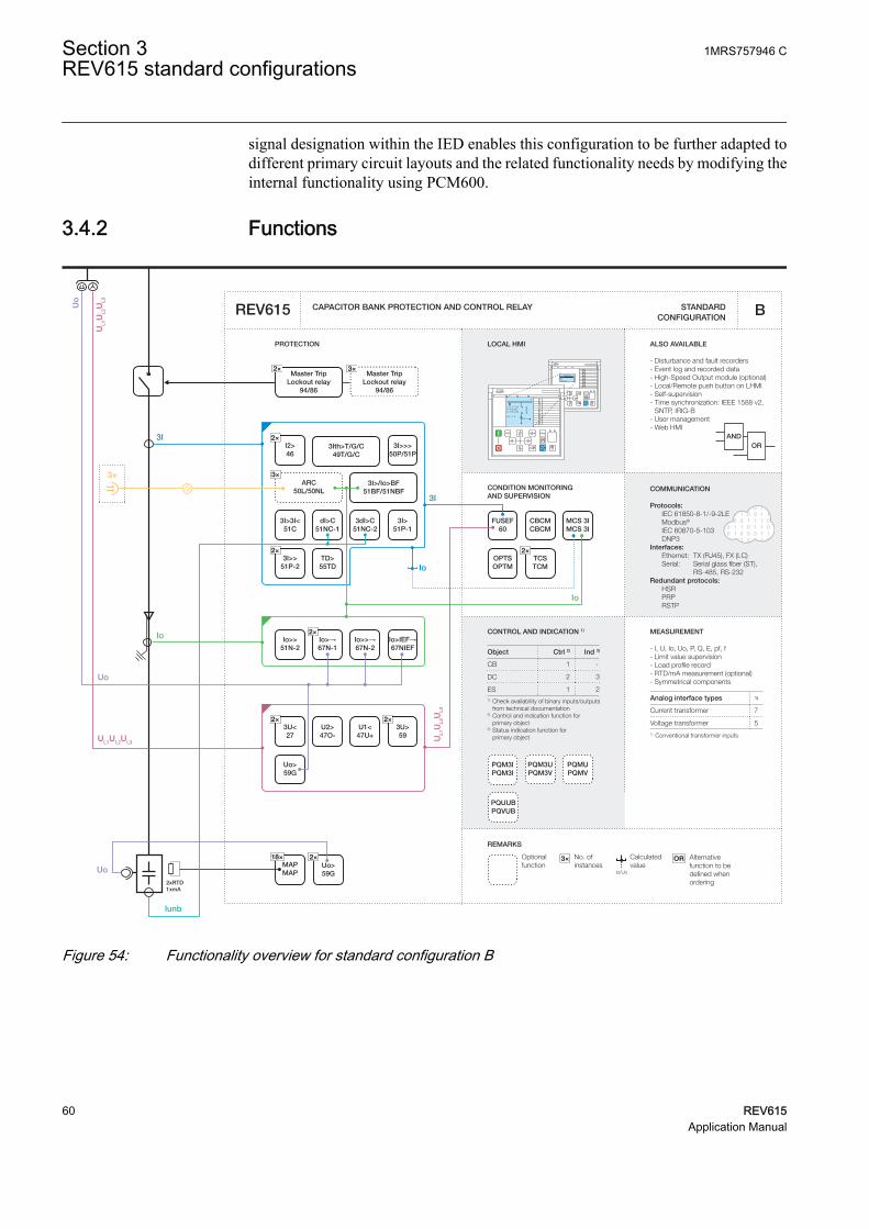
signal designation within the IED enables this configuration to be further adapted todifferent primary circuit layouts and the related functionality needs by modifying theinternal functionality using PCM600.
3.4.2 Functions
CONDITION MONITORING AND SUPERVISION
ORAND
CONTROL AND INDICATION 1) MEASUREMENT
CAPACITOR BANK PROTECTION AND CONTROL RELAY STANDARD CONFIGURATION
PROTECTION LOCAL HMI
Object Ctrl 2) Ind 3)
CB
DC
ES1) Check availability of binary inputs/outputs
from technical documentation2) Control and indication function for
primary object3) Status indication function for primary object
RL
ClearESCI
O
Configuration ASystemHMITimeAuthorization
RL
ClearESCI
O
U12 0. 0 kVP 0.00 kWQ 0.00 kVAr
IL2 0 A
A
REMARKS
Optionalfunction
No. ofinstances
Alternative function to be defined when ordering
OR
Io/Uo
Calculatedvalue
3×
REV615 B
COMMUNICATION
Protocols: IEC 61850-8-1/-9-2LE Modbus®
IEC 60870-5-103 DNP3Interfaces: Ethernet: TX (RJ45), FX (LC) Serial: Serial glass fiber (ST), RS-485, RS-232Redundant protocols: HSR PRP RSTP
- I, U, Io, Uo, P, Q, E, pf, f- Limit value supervision- Load profile record- RTD/mA measurement (optional)- Symmetrical components
7
5
Analog interface types 1)
Current transformer
Voltage transformer1) Conventional transformer inputs
1 -
2 3
1 2
ALSO AVAILABLE
- Disturbance and fault recorders- Event log and recorded data- High-Speed Output module (optional) - Local/Remote push button on LHMI- Self-supervision- Time synchronization: IEEE 1588 v2,
SNTP, IRIG-B- User management- Web HMI
Master TripLockout relay
94/86
PQM3IPQM3I
2×TCSTCM
MCS 3IMCS 3I
CBCMCBCM
OPTSOPTM
18×MAPMAP
2xRTD1xmA
Io>>51N-2
2×Io>→67N-1
Io>>→67N-2
2×3U<27
U2>47O-
U1<47U+
2×3U>59
Uo>59G
FUSEF60
2×I2>46
3I>>>50P/51P
3×ARC
50L/50NL3I>/Io>BF
51BF/51NBF
3I>51P-1
2×3I>>
51P-2TD>55TD
3I>3I<51C
3dI>C51NC-2
dI>C51NC-1
PQM3UPQM3V
PQMUPQMV
Uo>59G
3Ith>T/G/C49T/G/C
3I
3I
Io
Io
Io
Iunb
Io>IEF→67NIEF
UL1
UL2
UL3
UL1UL2UL3 UL1
UL2
UL3
Uo
Uo
3×
2×
Uo
Master TripLockout relay
94/86
3×2×
PQUUBPQVUB
GUID-393D9B25-06C8-42AE-A7D0-642BBCB89DBE V2 EN
Figure 54: Functionality overview for standard configuration B
Section 3 1MRS757946 CREV615 standard configurations
60 REV615Application Manual

3.4.2.1 Default I/O connections
Connector pins for each input and output are presented in the IED physicalconnections section.
Table 16: Default connections for binary inputs
Binary input DescriptionX110-BI1 Circuit breaker low gas pressure indication
X110-BI2 Circuit breaker spring charged indication
X110-BI3 Circuit breaker open indication
X110-BI4 Circuit breaker closed indication
X110-BI5 Circuit breaker truck out (test position) indication
X110-BI6 Circuit breaker truck in (service position) indication
X110-BI7 Earth switch open indication
X110-BI8 Earth switch closed indication
Table 17: Default connections for binary outputs
Binary output DescriptionX100-PO1 Close circuit breaker
X100-PO2 Breaker failure backup trip to upstream breaker
X100-SO1 General start indication
X100-SO2 General operate indication
X100-PO3 Open circuit breaker/trip coil 1
X100-PO4 Capacitor bank reconnection enable
X110-SO1 Overcurrent operate alarm
X110-SO2 Earth-fault operate alarm
X110-SO3 Capacitor protection operate alarm
X110-SO4 Voltage protection operate alarm
X110-HSO1 Arc protection instance 1 operate activated
X110-HSO2 Arc protection instance 2 operate activated
X110-HSO3 Arc protection instance 3 operate activated
Table 18: Default connections for LEDs
LED Description1 Overcurrent protection operated
2 Earth-fault protection operated
3 Capacitor or thermal overload protection operated
4 Capacitor overload alarm
5 Capacitor unbalance or negative phase sequence protection operator
6 Voltage protection operated
Table continues on next page
1MRS757946 C Section 3REV615 standard configurations
REV615 61Application Manual

LED Description7 Undercurrent or resonance protection operated
8 -
9 Disturbance recorder triggered
10 Supervision alarms
11 Arc-fault detected
3.4.2.2 Default disturbance recorder settings
Table 19: Default disturbance recorder analog channels
Channel Description1 IL1
2 IL2
3 IL3
4 Iunb
5 -
6 -
7 Io
8 Uo
9 U1
10 U2
11 U3
12 UoB
Table 20: Default disturbance recorder binary channels
Channel ID text Level trigger mode1 PHIPTOC1 - start Positive or Rising
2 PHHPTOC1 - start Positive or Rising
3 PHHPTOC2 - start Positive or Rising
4 PHLPTOC1 - start Positive or Rising
5 EFHPTOC1 - start Positive or Rising
6 DEFHPDEF1 - start Positive or Rising
7 DEFLPDEF1 - start Positive or Rising
8 DEFLPDEF2 - start Positive or Rising
9 NSPTOC1 - start Positive or Rising
10 NSPTOC2 - start Positive or Rising
11 T2PTTR1 - start Positive or Rising
12 COLPTOC1 - start ovload Positive or Rising
13 COLPTOC1 - start un I Positive or Rising
14 CUBPTOC1 - start Positive or Rising
Table continues on next page
Section 3 1MRS757946 CREV615 standard configurations
62 REV615Application Manual

Channel ID text Level trigger mode15 PSPTUV1 - start Positive or Rising
16 NSPTOV1 - start Positive or Rising
17 PHPTOV1 - start Positive or Rising
18 PHPTOV2 - start Positive or Rising
19 PHPTUV1 - start Positive or Rising
20 PHPTUV2 - start Positive or Rising
21 ROVPTOV1 - start Positive or Rising
22 PHIPTOC1 - operate Level trigger off
PHHPTOC1 - operate
PHHPTOC2 - operate
PHLPTOC1 - operate
23 EFLPTOC1 - operate Level trigger off
DEFLPDEF1 - operate
DEFLPDEF2 - operate
DEFHPDEF1 - operate
24 NSPTOC1 - operate Level trigger off
NSPTOC2 - operate
25 T2PTTR1 - operate Level trigger off
26 COLPTOC1 - operate ovload Level trigger off
27 COLPTOC1 - operate un I Level trigger off
28 CUBPTOC1 - operate Level trigger off
29 PSPTUV1 - operate Level trigger off
30 NSPTUV1 - operate Level trigger off
31 PHPTOV1 - operate Level trigger off
PHPTPOV2 - operate
32 PHPTUV1 - operate Level trigger off
PHPTUV2 - operate
33 ROVPTOV1 - operate Level trigger off
34 T2PTTR1 - alarm Level trigger off
35 SRCPTOC1 - alarm Positive or Rising
36 COLPTOC1 - alarm Level trigger off
37 SRCPTOC1 - operate Level trigger off
38 CCBRBRF1 - trret Level trigger off
39 CCBRBRF1 - trbu Level trigger off
40 CCSPVC1 - fail Level trigger off
41 SEQSPVC1 - fusef 3ph Level trigger off
42 SEQSPVC - fusef u Level trigger off
43 X110BI4 - CB closed Level trigger off
44 X110BI3 - CB opened Level trigger off
Table continues on next page
1MRS757946 C Section 3REV615 standard configurations
REV615 63Application Manual

Channel ID text Level trigger mode45 ARCSARC1 - ARC flt det Level trigger off
ARCSARC2 - ARC flt det
ARCSARC3 - ARC flt det
46 ARCSARC1 - operate Positive or Rising
47 ARCSARC2 - operate Positive or Rising
48 ARCSARC3 - operate Positive or Rising
3.4.3 Functional diagrams
The functional diagrams describe the default input, output, alarm LED and function-to-function connections. The default connections can be viewed and changed withPCM600 according to the application requirements.
The analog channels have fixed connections to the different function blocks inside theIED’s standard configuration. However, the 12 analog channels available for thedisturbance recorder function are freely selectable as a part of the disturbancerecorder’s parameter settings.
The capacitor phase currents as well as capacitor unbalance current to the IED are fedfrom a current transformer. The residual current to the IED is fed either fromresidually connected current transformers, an external core balance CT, neutral CT orinternally calculated.
The capacitor phase voltages to the IED are fed from a voltage transformer. Theresidual voltage to the IED is fed either from residually connected voltagetransformers, an open delta connected VT or internally calculated.
The IED offers six different settings group which can be set based on the individualneeds. Each group can be activated or deactivated using the setting group settingsavailable in the IED.
Depending on the communication protocol the required function block needs to beinstantiated in the configuration.
3.4.3.1 Functional diagrams for protection
The functional diagrams describe the IED's protection functionality in detail andaccording to the factory set default connections.
Four non-directional overcurrent stages are offered for capacitor overcurrent andshort-circuit protection.
Section 3 1MRS757946 CREV615 standard configurations
64 REV615Application Manual

PHIPTOC1BLOCKENA_MULT
OPERATESTART
PHLPTOC1BLOCKENA_MULT
OPERATESTART
PHHPTOC1BLOCKENA_MULT
OPERATESTART
PHHPTOC2BLOCKENA_MULT
OPERATESTART
OR6B1B2B3B4B5B6
O
PHLPTOC1_OPERATE
PHLPTOC1_OPERATE
PHHPTOC1_OPERATE
PHHPTOC1_OPERATE
PHHPTOC2_OPERATE
PHHPTOC2_OPERATE
PHIPTOC1_OPERATE
PHIPTOC1_OPERATE
PHLPTOC1_START
PHHPTOC1_START
PHHPTOC2_START
PHIPTOC1_START
OC_OPERATE
GUID-6E8841C3-F6CA-400D-8FB4-334950973E62 V1 EN
Figure 55: Overcurrent protection functions
Two negative-sequence overcurrent protection stages NSPTOC1 and NSPTOC2 areprovided for phase unbalance protection. These functions are used to protect thecapacitor against unbalance conditions. The negative-sequence overcurrentprotection functions are blocked in case of detection of a failure in the secondarycircuit of current transformer.
1MRS757946 C Section 3REV615 standard configurations
REV615 65Application Manual

NSPTOC1BLOCKENA_MULT
OPERATESTART
NSPTOC2BLOCKENA_MULT
OPERATESTART
ORB1B2
O
NSPTOC1_OPERATE
NSPTOC1_OPERATE
NSPTOC2_OPERATE
NSPTOC2_OPERATE
NSPTOC1_START
NSPTOC2_START
CCSPVC1_FAIL
CCSPVC1_FAIL
NSPTOC_OPERATE
GUID-5D442EE5-77B1-46F7-B8D8-B846D6DEF541 V2 EN
Figure 56: Negative-sequence overcurrent protection function
Four stages are provided for earth-fault protection. Three stages are dedicated fordirectional earth-fault protection.
DEFHPDEF1BLOCKENA_MULTRCA_CTL
OPERATESTART
DEFLPDEF1BLOCKENA_MULTRCA_CTL
OPERATESTART
DEFLPDEF2BLOCKENA_MULTRCA_CTL
OPERATESTART
DEFHPDEF1_OPERATE
DEFLPDEF2_OPERATE
DEFLPDEF1_OPERATE
DEFLPDEF2_START
DEFLPDEF1_START
DEFHPDEF1_START
OR6B1B2B3B4B5B6
O
EFHPTOC1_OPERATE
DEFHPDEF1_OPERATEDEFLPDEF2_OPERATEDEFLPDEF1_OPERATE
EF_OPERATE
EFHPTOC1BLOCKENA_MULT
OPERATESTART
EFHPTOC1_OPERATEEFHPTOC1_START
GUID-E57792A0-0380-4B27-AB24-8EB001BABA8F V1 EN
Figure 57: Earth-fault protection functions
Section 3 1MRS757946 CREV615 standard configurations
66 REV615Application Manual

The three-phase thermal overload protection T2PTTR1 with two time constantsdetects overload under varying load conditions. The BLK_CLOSE output of thefunction is used to block the closing operation of circuit breaker.
T2PTTR1BLOCKTEMP_AMB
OPERATESTARTALARM
BLK_CLOSE T2PTTR1_BLK_CLOSE
T2PTTR1_OPERATET2PTTR1_STARTT2PTTR1_ALARM
GUID-39968CD7-297E-451D-BE56-97E126A257D4 V1 EN
Figure 58: Thermal overcurrent protection function
The circuit breaker failure protection CCBRBRF1 is initiated via the START input bynumber of different protection functions available in the IED. The circuit breakerfailure protection function offers different operating modes associated with the circuitbreaker position and the measured phase and residual currents.
The circuit breaker failure protection function has two operating outputs: TRRET andTRBU. The TRRET operate output is used for retripping its own breaker throughTRPPTRC2_TRIP. The TRBU output is used to give a backup trip to the breakerfeeding upstream. For this purpose, the TRBU operate output signal is connected to thebinary output X100:PO2.
CCBRBRF1BLOCKSTARTPOSCLOSECB_FAULT
CB_FAULT_ALTRBU
TRRET
OR6B1B2B3B4B5B6
O
OR6B1B2B3B4B5B6
O
OR6B1B2B3B4B5B6
O
OR6B1B2B3B4B5B6
O
OR6B1B2B3B4B5B6
O
OR6B1B2B3B4B5B6
O
CCBRBRF1_TRBUX110_BI4_CB_CLOSED
EFHPTOC1_OPERATE
DEFHPDEF1_OPERATE
NSPTOC1_OPERATENSPTOC2_OPERATE
T2PTTR1_OPERATE
COLPTOC1_OPR_OVLODCOLPTOC1_OPR_UN_I
CUBPTOC1_OPERATE
ARCSARC1_OPERATEARCSARC2_OPERATEARCSARC3_OPERATE
PHLPTOC1_OPERATE
PHHPTOC1_OPERATEPHHPTOC2_OPERATE
PHIPTOC1_OPERATE
DEFLPDEF2_OPERATEDEFLPDEF1_OPERATE
PSPTUV1_OPERATE
PHPTOV1_OPERATEPHPTOV2_OPERATEPHPTUV1_OPERATEPHPTUV2_OPERATE
ROVPTOV1_OPERATE
SRCPTOC1_OPERATE
NSPTOV1_OPERATE
CCBRBRF1_TRRET
GUID-A5095A7B-4341-46B8-B10E-07849EF3D52D V1 EN
Figure 59: Circuit breaker failure protection function
1MRS757946 C Section 3REV615 standard configurations
REV615 67Application Manual

Three arc protection stages ARCSARC1...3 are included as optional functions. Thearc protection offers individual function blocks for three arc sensors that can beconnected to the IED. Each arc protection function block has two different operationmodes, that is, with or without the phase and residual current check.
The operate signals from ARCSARC1...3 are connected to both trip logic TRPPTRC1and TRPPTRC2. If the IED has been ordered with high speed binary outputs, theindividual operate signals from ARCSARC1...3 are connected to dedicated trip logicTRPPTRC3...5. The outputs of TRPPTRC3...5 are available at high speed outputsX110:HSO1, X110:HSO2 and X110:HSO3.
Section 3 1MRS757946 CREV615 standard configurations
68 REV615Application Manual

ARCSARC1BLOCKREM_FLT_ARCOPR_MODE
OPERATEARC_FLT_DET
ARCSARC2BLOCKREM_FLT_ARCOPR_MODE
OPERATEARC_FLT_DET
ARCSARC3BLOCKREM_FLT_ARCOPR_MODE
OPERATEARC_FLT_DET
OR6B1B2B3B4B5B6
O
ARCSARC1_OPERATE
ARCSARC1_OPERATE
ARCSARC2_OPERATE
ARCSARC2_OPERATE
ARCSARC3_OPERATE
ARCSARC3_OPERATE
ARCSARC1_ARC_FLT_DET
ARCSARC2_ARC_FLT_DET
ARCSARC3_ARC_FLT_DET
ARCSARC_OPERATE
GUID-FC4A254A-CE67-47F8-9D4E-27895E228DB8 V1 EN
TRPPTRC3BLOCKOPERATERST_LKOUT
TRIPCL_LKOUT
TRPPTRC4BLOCKOPERATERST_LKOUT
TRIPCL_LKOUT
TRPPTRC5BLOCKOPERATERST_LKOUT
TRIPCL_LKOUT
TRPPTRC3_TRIP
TRPPTRC4_TRIP
TRPPTRC5_TRIP
ARCSARC1_OPERATE
ARCSARC2_OPERATE
ARCSARC3_OPERATE
GUID-47E92FB9-061E-414C-AD0F-91C1C3F55C35 V1 EN
Figure 60: Arc protection with dedicated HSO
Three-phase overload protection for shunt capacitor banks COLPTOC1 providesprotection against overloads caused due to harmonic currents and overvoltage in shuntcapacitor banks. The BLK_CLOSE output of the function is used to block the closingoperation of circuit breaker.
1MRS757946 C Section 3REV615 standard configurations
REV615 69Application Manual

COLPTOC1BLOCKCB_CLOSED
OPR_OVLODOPR_UN_I
ST_OVLODST_UN_I
ALARMBLK_CLOSE
X110_BI4_CB_CLOSED
COLPTOC1_BLK_CLOSE
COLPTOC1_OPR_OVLODCOLPTOC1_OPR_UN_ICOLPTOC1_ST_OVLODCOLPTOC1_ST_UN_ICOLPTOC1_ALARM
GUID-CF723E8E-F01F-4A51-BE58-2083B45AC03F V1 EN
Figure 61: Capacitor bank overload protection function
Current unbalance protection for shunt capacitor banks CUBPTOC1 is provided in theapplication configuration to protect double-Y type connected capacitor banks againstinternal faults. The function is suitable for protection of internally fused, externallyfused and fuse-less capacitor bank applications. If the application contains an H-bridge type capacitor bank, CUBPTOC1 function can be replaced by HCUBPTOCfunction which has been designed for H-bridge type capacitor banks.
CUBPTOC1BLOCK OPERATE
STARTALARM
CUBPTOC1_OPERATECUBPTOC1_START
GUID-E065DA6C-6BA6-4373-B7D4-3F7A65C73BDD V1 EN
Figure 62: Unbalance protection for H-bridge shunt capacitor banks
Shunt capacitor bank switching resonance protection, current based, SRCPTOC1 isused for three-phase resonance detection caused by capacitor switching or due totopology changes in the network.
SRCPTOC1BLOCKRESO_IN
ALARMOPERATE SRCPTOC1_OPERATE
SRCPTOC1_ALARM
GUID-00CB236D-D5DF-47C7-B0D4-1542CA5340B7 V1 EN
Figure 63: Capacitor bank resonance protection
Two overvoltage and undervoltage protection stages PHPTOV and PHPTUV offerprotection against abnormal phase voltage conditions. Positive-sequenceundervoltage protection PSPTUV1 and negative-sequence overvoltage protectionNSPTOV1 functions enable voltage-based unbalance protection. A failure in thevoltage measuring circuit is detected by the fuse failure function and the activation isconnected to block undervoltage protection functions and voltage based unbalanceprotection functions to avoid faulty tripping.
Section 3 1MRS757946 CREV615 standard configurations
70 REV615Application Manual

PHPTOV1BLOCK OPERATE
START
PHPTOV2BLOCK OPERATE
START
ORB1B2
O
PHPTOV1_OPERATE
PHPTOV1_OPERATE
PHPTOV2_OPERATE
PHPTOV2_OPERATE
PHPTOV1_START
PHPTOV2_START
PHPTOV_OPERATE
GUID-1FAE48E8-3B41-4120-8723-3A35E2A95B7B V1 EN
Figure 64: Overvoltage protection function
PHPTUV1BLOCK OPERATE
START
PHPTUV2BLOCK OPERATE
START
ORB1B2
O
PHPTUV1_OPERATE
PHPTUV1_OPERATE
PHPTUV2_OPERATE
PHPTUV2_OPERATE
PHPTUV1_START
PHPTUV2_START
SEQSPVC1_FUSEF_U
SEQSPVC1_FUSEF_U
PHPTUV_OPERATE
GUID-40782C23-9A95-443B-A63D-3FC19DA4DCFD V2 EN
Figure 65: Undervoltage protection function
NSPTOV1BLOCK OPERATE
STARTNSPTOV1_OPERATENSPTOV1_START
SEQSPVC1_FUSEF_U
GUID-95CB25CE-F1C6-48DA-8F05-9E51C6022D29 V2 EN
Figure 66: Negative-sequence overvoltage protection function
1MRS757946 C Section 3REV615 standard configurations
REV615 71Application Manual
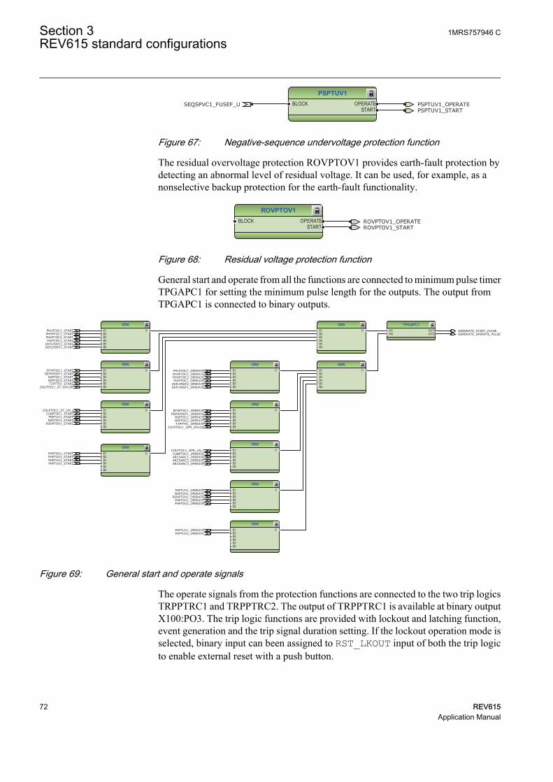
PSPTUV1BLOCK OPERATE
STARTPSPTUV1_OPERATEPSPTUV1_START
SEQSPVC1_FUSEF_U
GUID-A43E5917-B556-413C-AE66-76CEB81EC0BA V2 EN
Figure 67: Negative-sequence undervoltage protection function
The residual overvoltage protection ROVPTOV1 provides earth-fault protection bydetecting an abnormal level of residual voltage. It can be used, for example, as anonselective backup protection for the earth-fault functionality.
ROVPTOV1BLOCK OPERATE
STARTROVPTOV1_OPERATEROVPTOV1_START
GUID-DFEF6E25-69DA-4D8B-B25E-B501296A6976 V1 EN
Figure 68: Residual voltage protection function
General start and operate from all the functions are connected to minimum pulse timerTPGAPC1 for setting the minimum pulse length for the outputs. The output fromTPGAPC1 is connected to binary outputs.
TPGAPC1IN1IN2
OUT1OUT2
OR6B1B2B3B4B5B6
O
OR6B1B2B3B4B5B6
O
OR6B1B2B3B4B5B6
O
OR6B1B2B3B4B5B6
O
OR6B1B2B3B4B5B6
O
OR6B1B2B3B4B5B6
O
OR6B1B2B3B4B5B6
O
OR6B1B2B3B4B5B6
O
OR6B1B2B3B4B5B6
O
OR6B1B2B3B4B5B6
O
OR6B1B2B3B4B5B6
O
GENERATE_START_PULSEGENERATE_OPERATE_PULSE
EFHPTOC1_OPERATEDEFHPDEF1_OPERATE
NSPTOC1_OPERATENSPTOC2_OPERATET2PTTR1_OPERATE
COLPTOC1_OPR_OVLOD
COLPTOC1_OPR_UN_ICUBPTOC1_OPERATEARCSARC1_OPERATEARCSARC2_OPERATEARCSARC3_OPERATE
PHLPTOC1_OPERATEPHHPTOC1_OPERATEPHHPTOC2_OPERATEPHIPTOC1_OPERATE
DEFLPDEF2_OPERATEDEFLPDEF1_OPERATE
PSPTUV1_OPERATE
PHPTOV1_OPERATEPHPTOV2_OPERATE
PHPTUV1_OPERATEPHPTUV2_OPERATE
ROVPTOV1_OPERATENSPTOV1_OPERATE
PHLPTOC1_STARTPHHPTOC1_STARTPHHPTOC2_STARTPHIPTOC1_START
DEFLPDEF2_STARTDEFLPDEF1_START
EFHPTOC1_STARTDEFHPDEF1_START
NSPTOC1_STARTNSPTOC2_STARTT2PTTR1_START
COLPTOC1_ST_OVLOD
COLPTOC1_ST_UN_ICUBPTOC1_START
PSPTUV1_STARTNSPTOV1_START
ROVPTOV1_START
PHPTOV1_STARTPHPTOV2_STARTPHPTUV1_STARTPHPTUV2_START
GUID-B0156B17-37B4-42D9-BB6D-D59D5EEA07B9 V1 EN
Figure 69: General start and operate signals
The operate signals from the protection functions are connected to the two trip logicsTRPPTRC1 and TRPPTRC2. The output of TRPPTRC1 is available at binary outputX100:PO3. The trip logic functions are provided with lockout and latching function,event generation and the trip signal duration setting. If the lockout operation mode isselected, binary input can been assigned to RST_LKOUT input of both the trip logicto enable external reset with a push button.
Section 3 1MRS757946 CREV615 standard configurations
72 REV615Application Manual

Three other trip logics TRPPTRC3...5 are available if the IED is ordered with highspeed binary outputs options.
TRPPTRC1BLOCKOPERATERST_LKOUT
TRIPCL_LKOUT
OR6B1B2B3B4B5B6
O
OR6B1B2B3B4B5B6
O
OR6B1B2B3B4B5B6
O
OR6B1B2B3B4B5B6
O
OR6B1B2B3B4B5B6
O
TRPPTRC1_TRIP
EFHPTOC1_OPERATEDEFHPDEF1_OPERATE
NSPTOC1_OPERATENSPTOC2_OPERATET2PTTR1_OPERATE
COLPTOC1_OPR_OVLOD
COLPTOC1_OPR_UN_I
CUBPTOC1_OPERATEARCSARC1_OPERATEARCSARC2_OPERATEARCSARC3_OPERATE
PHLPTOC1_OPERATEPHHPTOC1_OPERATEPHHPTOC2_OPERATEPHIPTOC1_OPERATE
DEFLPDEF2_OPERATEDEFLPDEF1_OPERATE
PSPTUV1_OPERATEPHPTOV1_OPERATEPHPTOV2_OPERATEPHPTUV1_OPERATEPHPTUV2_OPERATE
ROVPTOV1_OPERATE
SRCPTOC1_OPERATE
NSPTOV1_OPERATE
GUID-DA366F32-487C-4C0D-A8D7-5C9A8E4D2B38 V1 EN
Figure 70: Trip logic TRPPTRC1
OR6B1B2B3B4B5B6
O
TRPPTRC2BLOCKOPERATERST_LKOUT
TRIPCL_LKOUT
OR6B1B2B3B4B5B6
O
OR6B1B2B3B4B5B6
O
OR6B1B2B3B4B5B6
O
OR6B1B2B3B4B5B6
O
OR6B1B2B3B4B5B6
O
TRPPTRC2_TRIP
EFHPTOC1_OPERATEDEFHPDEF1_OPERATE
NSPTOC1_OPERATENSPTOC2_OPERATET2PTTR1_OPERATE
COLPTOC1_OPR_OVLOD
COLPTOC1_OPR_UN_I
CUBPTOC1_OPERATEARCSARC1_OPERATEARCSARC2_OPERATEARCSARC3_OPERATE
PHLPTOC1_OPERATEPHHPTOC1_OPERATEPHHPTOC2_OPERATEPHIPTOC1_OPERATE
DEFLPDEF2_OPERATEDEFLPDEF1_OPERATE
PSPTUV1_OPERATEPHPTOV1_OPERATEPHPTOV2_OPERATEPHPTUV1_OPERATEPHPTUV2_OPERATE
ROVPTOV1_OPERATE
SRCPTOC1_OPERATE
NSPTOV1_OPERATECCBRBRF1_TRRET
GUID-242BA8D7-D803-461D-88B3-8D1431CE5982 V1 EN
Figure 71: Trip logic TRPPTRC2
1MRS757946 C Section 3REV615 standard configurations
REV615 73Application Manual

3.4.3.2 Functional diagrams for disturbance recorder
The START and the OPERATE outputs from the protection stages are routed to triggerthe disturbance recorder or, alternatively, only to be recorded by the disturbancerecorder depending on the parameter settings. Additionally, the selected signals fromdifferent functions and the few binary inputs are also connected to the disturbancerecorder.
RDRE1C1C2C3C4C5C6C7C8C9C10C11C12C13C14C15C16C17C18C19C20C21C22C23C24C25C26C27C28C29C30C31C32C33C34C35C36C37C38C39C40C41C42C43C44C45C46C47C48C49C50C51C52C53C54C55C56C57C58C59C60C61C62C63C64
TRIGGERED
OR6B1B2B3B4B5B6
O
OR6B1B2B3B4B5B6
O
ORB1B2
O
OR6B1B2B3B4B5B6
O
ORB1B2
O
ORB1B2
OCCBRBRF1_TRBU
X110_BI3_CB_OPENEDX110_BI4_CB_CLOSED
EFHPTOC1_OPERATE
DEFHPDEF1_OPERATE
NSPTOC1_OPERATENSPTOC2_OPERATE T2PTTR1_OPERATE
COLPTOC1_OPR_OVLODCOLPTOC1_OPR_UN_ICUBPTOC1_OPERATE
ARCSARC1_OPERATEARCSARC2_OPERATEARCSARC3_OPERATE
PHLPTOC1_OPERATE
PHHPTOC1_OPERATEPHHPTOC2_OPERATE
PHIPTOC1_OPERATE
DEFLPDEF2_OPERATEDEFLPDEF1_OPERATE
PSPTUV1_OPERATE
PHPTOV1_OPERATEPHPTOV2_OPERATE
PHPTUV1_OPERATEPHPTUV2_OPERATE
ROVPTOV1_OPERATE
SRCPTOC1_OPERATE
NSPTOV1_OPERATE
CCBRBRF1_TRRET
PHLPTOC1_START
PHHPTOC1_STARTPHHPTOC2_START
PHIPTOC1_START
DEFLPDEF2_STARTDEFLPDEF1_START
EFHPTOC1_STARTDEFHPDEF1_START
NSPTOC1_STARTNSPTOC2_STARTT2PTTR1_START
COLPTOC1_ST_OVLODCOLPTOC1_ST_UN_I
CUBPTOC1_STARTPSPTUV1_STARTNSPTOV1_START
ROVPTOV1_START
PHPTOV1_STARTPHPTOV2_STARTPHPTUV1_STARTPHPTUV2_START
CCSPVC1_FAIL
SEQSPVC1_FUSEF_U
ARCSARC1_ARC_FLT_DETARCSARC2_ARC_FLT_DETARCSARC3_ARC_FLT_DET
T2PTTR1_ALARMSRCPTOC1_ALARMCOLPTOC1_ALARM
SEQSPVC1_FUSEF_3PH
DISTURB_RECORD_TRIGGERED
GUID-BB8813B7-5E22-42CA-A7C1-4F454043B82E V2 EN
Figure 72: Disturbance recorder
3.4.3.3 Functional diagrams for condition monitoring
Failures in phase current measuring circuits are detected by CCSPVC1. When afailure is detected, it can be used to block current protection functions that aremeasuring calculated sequence component currents or residual current to avoidunnecessary operation.
CCSPVC1BLOCK FAIL
ALARMCCSPVC1_FAILCCSPVC1_ALARM
GUID-0901A287-4CF6-41C5-ABC9-7CFACAF28E93 V2 EN
Figure 73: Current circuit supervision function
Section 3 1MRS757946 CREV615 standard configurations
74 REV615Application Manual

The fuse failure supervision SEQSPVC1 detects failures in the voltage measurementcircuits at bus side. Failures, such as an open MCB, raise an alarm.
SEQSPVC1BLOCKCB_CLOSEDDISCON_OPENMINCB_OPEN
FUSEF_3PHFUSEF_UX110_BI4_CB_CLOSED
X110_BI5_CB_TRUCK_IN_TESTSEQSPVC1_FUSEF_USEQSPVC1_FUSEF_3PH
GUID-30621F93-B811-4D23-A76B-3363C75366E2 V2 EN
Figure 74: Fuse failure supervision function
The circuit-breaker condition monitoring function SSCBR1 supervises the switchstatus based on the connected binary input information and the measured currentlevels. SSCBR1 introduces various supervision methods.
SSCBR1BLOCKPOSOPENPOSCLOSEOPEN_CB_EXECLOSE_CB_EXEPRES_ALM_INPRES_LO_INSPR_CHR_STSPR_CHRRST_IPOWRST_CB_WEARRST_TRV_TRST_SPR_T
TRV_T_OP_ALMTRV_T_CL_ALMSPR_CHR_ALM
OPR_ALMOPR_LO
IPOW_ALMIPOW_LO
CB_LIFE_ALMMON_ALM
PRES_ALMPRES_LO
OPENPOSINVALIDPOSCLOSEPOS
CB_CLOSE_COMMANDCB_OPEN_COMMAND
X110_BI3_CB_OPENEDX110_BI4_CB_CLOSED
X110_BI2_CB_SPRING_CHARGED
X110_BI1_GAS_PRESSURE_ALARM
CB_SPRING_DISCHARGED
SSCBR1_TRV_T_OP_ALMSSCBR1_TRV_T_CL_ALMSSCBR1_SPR_CHR_ALMSSCBR1_OPR_ALMSSCBR1_OPR_LOSSCBR1_IPOW_ALMSSCBR1_IPOW_LOSSCBR1_CB_LIFE_ALMSSCBR1_MON_ALMSSCBR1_PRES_ALMSSCBR1_PRES_LO
GUID-82B807F1-4925-4F86-B2AD-E9C68E4E2077 V1 EN
Figure 75: Condition monitoring function
ORB1B2
O
OR6B1B2B3B4B5B6
O
OR6B1B2B3B4B5B6
O
SSCBR1_TRV_T_OP_ALMSSCBR1_TRV_T_CL_ALMSSCBR1_SPR_CHR_ALM
SSCBR1_OPR_ALMSSCBR1_OPR_LO
SSCBR1_IPOW_ALM
SSCBR1_IPOW_LOSSCBR1_CB_LIFE_ALM
SSCBR1_MON_ALMSSCBR1_PRES_ALM
SSCBR1_PRES_LO
SSCBR1_ALARMS
GUID-5A3707E3-871F-4F33-8A76-59974E91E7ED V1 EN
Figure 76: Logic for circuit breaker monitoring alarm
NOTIN OUTX110_BI2_CB_SPRING_CHARGED CB_SPRING_DISCHARGED
GUID-E93EEC82-5605-4086-B786-EA15DE48AA1B V1 EN
Figure 77: Logic for the start of circuit breaker spring charging
Two separate trip circuit supervision functions are included, TCSSCBR1 for poweroutput X100:PO3 and TCSSCBR2 for power output X100:PO4. These functions areblocked by the master trip TRPPTRC1 and TRPPTRC2 and the circuit breaker opensignal.
1MRS757946 C Section 3REV615 standard configurations
REV615 75Application Manual

It is assumed that there is no external resistor in the circuit breakertripping coil circuit connected in parallel with the circuit breakernormally open auxiliary contact.
TCSSCBR1BLOCK ALARM
TCSSCBR2BLOCK ALARM
ORB1B2
O
TCSSCBR1_ALARM
TCSSCBR1_ALARM
TCSSCBR2_ALARM
TCSSCBR2_ALARM
TCSSCBR_BLOCKING
TCSSCBR_BLOCKING
TCSSCBR_ALARM
GUID-AAF693BE-5F31-4350-8844-CB6B0394FB9A V1 EN
Figure 78: Trip circuit supervision function
OR6B1B2B3B4B5B6
O
X110_BI3_CB_OPENED
TRPPTRC1_TRIPTRPPTRC2_TRIP
TCSSCBR_BLOCKING
GUID-7251F682-D8AB-4FD2-97B0-C398FA983917 V1 EN
Figure 79: Logic for blocking trip circuit supervision function
3.4.3.4 Functional diagrams for control and interlocking
There are two types of disconnector and earthing switch function blocks available.DCSXSWI1...3 and ESSXSWI1...2 are status only type, and DCXSWI1...2 andESXSWI1 are controllable type. By default, the status only blocks are connected instandard configuration. The disconnector (CB truck) and line side earthing switchstatus information are connected to DCSXSWI1 and ESSXSI1.
DCSXSWI1POSOPENPOSCLOSE
OPENPOSCLOSEPOS
OKPOS DCSXSWI1_OKPOS
X110_BI5_CB_TRUCK_IN_TESTX110_BI6_CB_TRUCK_IN_SERVICE
GUID-917DED22-0873-4158-B452-356037D604B5 V1 EN
Figure 80: Disconnector control logic
Section 3 1MRS757946 CREV615 standard configurations
76 REV615Application Manual

ESSXSWI1POSOPENPOSCLOSE
OPENPOSCLOSEPOS
OKPOS
ESSXSWI1_OPENPOSX110_BI7_ES1_OPENEDX110_BI8_ES1_CLOSED
GUID-E4232E76-8561-47E0-8630-6BF27FA27A04 V1 EN
Figure 81: Earth-switch control logic
The circuit breaker closing is enabled when the ENA_CLOSE input is activated. Theinput can be activated by the configuration logic, which is a combination of thedisconnector or breaker truck and earth-switch position status, status of the trip logics,gas pressure alarm and circuit breaker spring charging status.
The OKPOS output from DCSXSWI defines whether the disconnector or breakertruck is definitely either open (in test position) or close (in service position). Thisoutput, together with the open earth-switch and non-active trip signals, activates theclose-enable signal to the circuit-breaker control function block. The open operationfor circuit breaker is always enabled.
The SYNC_ITL_BYP input can be used, for example, to always enable the closing ofthe circuit breaker when the circuit breaker truck is in the test position, despite theinterlocking conditions being active when the circuit breaker truck is closed in serviceposition.
CBXCBR1POSOPENPOSCLOSEENA_OPENENA_CLOSEBLK_OPENBLK_CLOSEAU_OPENAU_CLOSETRIPSYNC_OKSYNC_ITL_BYP
SELECTEDEXE_OPEXE_CL
OP_REQCL_REQ
OPENPOSCLOSEPOS
OKPOSOPEN_ENAD
CLOSE_ENAD
TRUE
X110_BI3_CB_OPENEDX110_BI4_CB_CLOSED
CBXCBR1_ENA_CLOSECBXCBR1_EXE_CLCBXCBR1_EXE_OP
CBXCBR1_BLK_CLOSEFALSE
CBXCBR1_AU_OPENCBXCBR1_AU_CLOSE
GUID-662D3A55-AC01-4504-B854-B59C7E96A95B V2 EN
Figure 82: Circuit breaker control logic: Circuit breaker 1
Connect the additional signals required for the application for closingand opening of circuit breaker.
ORB1B2
O CB_CLOSE_COMMANDCBXCBR1_EXE_CL
GUID-94855B51-1607-4D62-B689-F8DE655DAD57 V1 EN
Figure 83: Circuit breaker control logic: Signals for closing coil of circuit breaker
1MRS757946 C Section 3REV615 standard configurations
REV615 77Application Manual

OR6B1B2B3B4B5B6
O CB_OPEN_COMMANDTRPPTRC1_TRIPCBXCBR1_EXE_OP
GUID-977C3B88-70DB-4FBD-802A-88A08B6A1E08 V1 EN
Figure 84: Circuit breaker control logic: Signals for opening coil of circuit breaker
AND6B1B2B3B4B5B6
O
NOTIN OUT
NOTIN OUT
NOTIN OUT
CBXCBR1_ENA_CLOSE
TRPPTRC1_TRIP
DCSXSWI1_OKPOSX110_BI2_CB_SPRING_CHARGED
X110_BI1_GAS_PRESSURE_ALARM
ESSXSWI1_OPENPOS
TRPPTRC2_TRIP
GUID-13A2F026-96B7-4F6A-9FCD-9334B5E4A576 V1 EN
Figure 85: Circuit breaker close enable logic
OR6B1B2B3B4B5B6
O CBXCBR1_BLK_CLOSET2PTTR1_BLK_CLOSE
COLPTOC1_BLK_CLOSE
GUID-DB3717DF-6999-49B1-8DF7-FF9CDED1FF5B V1 EN
Figure 86: Circuit breaker close blocking logic
The configuration includes logic for generating circuit breaker external closing andopening command with IED in local or remote mode.
Check the logic for the external circuit breaker closing command andmodify it according to the application.
Connect additional signals for opening and closing of circuit breakerin local or remote mode, if applicable for the configuration.
ANDB1B2
O
ANDB1B2
O
ORB1B2
O
FALSE
FALSE
CBXCBR1_AU_CLOSE
CONTROL_LOCAL
CONTROL_REMOTE
GUID-3893E4E5-21BD-4A79-AB47-865162E9ECEF V1 EN
Figure 87: External closing command for circuit breaker
Section 3 1MRS757946 CREV615 standard configurations
78 REV615Application Manual

ANDB1B2
O
ANDB1B2
O
ORB1B2
O
FALSE
FALSE
CBXBCR1_AU_OPEN
CONTROL_LOCAL
CONTROL_REMOTE
GUID-E4861647-EF79-432A-B3B7-344BE9086611 V1 EN
Figure 88: External opening command for circuit breaker
3.4.3.5 Functional diagrams for measurement functions
The phase current inputs to the IED are measured by the three-phase currentmeasurement function CMMXU1. The current input is connected to the X120 card inthe back panel. The sequence current measurement CSMSQI1 measures the sequencecurrent and the residual current measurement RESCMMXU1 measures the residualcurrent.
Three-phase capacitor unbalance current measurement is available in CUBPTOCprotection function.
The three-phase capacitor phase voltage inputs to the IED are measured by three-phase voltage measurement VMMXU1. The voltage input is connected to the X130card in the back panel. The sequence voltage measurement VSMSQI1 measures thesequence voltage and the residual voltage measurement RESVMMXU1 measures theresidual voltage. It is also possible to measure capacitor unbalance voltage by theresidual voltage measurement RESVMMXU2.
The measurements can be seen in the LHMI and they are available under themeasurement option in the menu selection. Based on the settings, function blocks cangenerate low alarm or warning and high alarm or warning signals for the measuredcurrent values.
The frequency measurement FMMXU1 of the power system and three-phase powerand energy measurement PEMMXU1 are available. The load profile functionLDPRLRC1 is included in the measurements sheet. LDPRLRC1 offers the ability toobserve the loading history of the corresponding feeder.
Current total demand distortion CMHAI1 and voltage total harmonic distortionVMHAI1 can be used to measure the harmonic contents of the phase current and phasevoltages. The voltage variation that is sage and swells can be measured by voltagevariation PHQVVR1. By default these power quality functions are not included in theconfiguration. Depending on the application, the needed logic connections can bemade by PCM600.
CMMXU1BLOCK HIGH_ALARM
HIGH_WARNLOW_WARN
LOW_ALARM
GUID-7D33AD69-87B7-4875-B6C5-BCD11765D01E V1 EN
Figure 89: Current measurement: Three-phase current measurement
1MRS757946 C Section 3REV615 standard configurations
REV615 79Application Manual
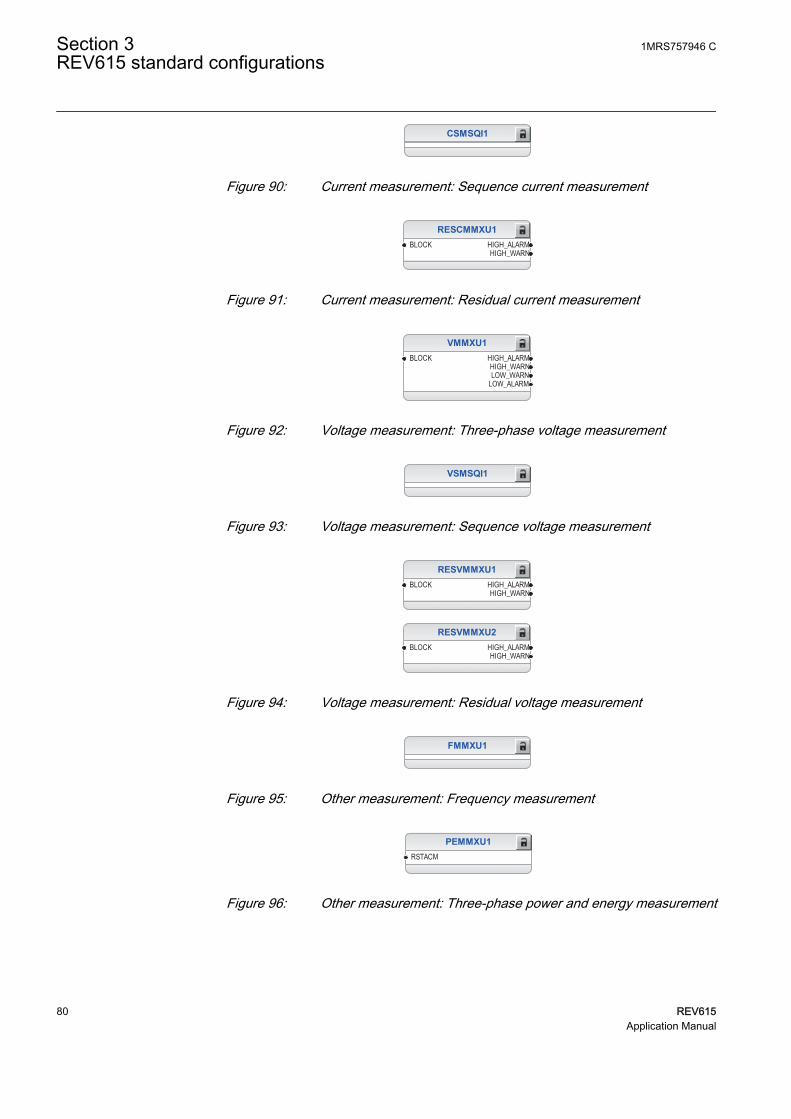
CSMSQI1
GUID-2E927E0C-A69B-4BAF-AE6C-F4C36A364C7A V1 EN
Figure 90: Current measurement: Sequence current measurement
RESCMMXU1BLOCK HIGH_ALARM
HIGH_WARN
GUID-DE551B8B-EB01-4A43-A1E6-7F71A3582127 V1 EN
Figure 91: Current measurement: Residual current measurement
VMMXU1BLOCK HIGH_ALARM
HIGH_WARNLOW_WARN
LOW_ALARM
GUID-DC4AF28A-8EDC-4C11-BE1F-FA53B6AAF32C V1 EN
Figure 92: Voltage measurement: Three-phase voltage measurement
VSMSQI1
GUID-65195485-13A8-499C-A42B-EB13420C3572 V1 EN
Figure 93: Voltage measurement: Sequence voltage measurement
RESVMMXU1BLOCK HIGH_ALARM
HIGH_WARN
GUID-EC2F4C74-8D81-49C9-ACEC-2AA8A2FB2A08 V1 EN
RESVMMXU2BLOCK HIGH_ALARM
HIGH_WARN
GUID-5064DB91-B408-4F8F-8663-3CAAE80AB1A1 V1 EN
Figure 94: Voltage measurement: Residual voltage measurement
FMMXU1
GUID-54CC5EF8-58FF-4BE0-B949-67F9EBF71866 V1 EN
Figure 95: Other measurement: Frequency measurement
PEMMXU1RSTACM
GUID-CC1BD7C9-AE56-43AF-B5D7-CDAD75F66C3A V1 EN
Figure 96: Other measurement: Three-phase power and energy measurement
Section 3 1MRS757946 CREV615 standard configurations
80 REV615Application Manual

FLTRFRC1BLOCKCB_CLRD
GUID-4D1D82CD-D056-48F0-8256-7DEE5B9EB508 V2 EN
Figure 97: Other measurement: Data monitoring
LDPRLRC1RSTMEM MEM_WARN
MEM_ALARM
GUID-E8309685-F8F7-4A24-B7C7-B4013CAAF73C V2 EN
Figure 98: Other measurement: Load profile record
1MRS757946 C Section 3REV615 standard configurations
REV615 81Application Manual

3.4.3.6 Functional diagrams for I/O and alarms LEDs
ORB1B2
O
ORB1B2
O
ORB1B2
O
ORB1B2
O
ORB1B2
O
ORB1B2
O
ORB1B2
O
ORB1B2
O
X110_BI3_CB_OPENED
X110_BI4_CB_CLOSED
X110_BI2_CB_SPRING_CHARGED
X110_BI1_GAS_PRESSURE_ALARM
X110_BI5_CB_TRUCK_IN_TEST
X110_BI6_CB_TRUCK_IN_SERVICE
X110_BI7_ES1_OPENED
X110_BI8_ES1_CLOSED
X110 (BIO-H).X110-Input 8
X110 (BIO).X110-Input 6
X110 (BIO-H).X110-Input 2
X110 (BIO).X110-Input 5
X110 (BIO).X110-Input 3
X110 (BIO).X110-Input 2
X110 (BIO).X110-Input 8
X110 (BIO).X110-Input 4
X110 (BIO).X110-Input 1
X110 (BIO-H).X110-Input 3
X110 (BIO-H).X110-Input 4
X110 (BIO-H).X110-Input 7
X110 (BIO-H).X110-Input 5
X110 (BIO).X110-Input 7
X110 (BIO-H).X110-Input 1
X110 (BIO-H).X110-Input 6
GUID-6882F0CC-DED6-478D-A3D1-1212DEBF94EE V1 EN
Figure 99: Default binary inputs - X110 terminal block
Section 3 1MRS757946 CREV615 standard configurations
82 REV615Application Manual

OC_OPERATE_PULSE
EF_OPERATE_PULSE
TRPPTRC3_TRIP
TRPPTRC4_TRIP
TRPPTRC5_TRIP
CAPACITOR_PROT_OPERATE_PULSE
VOLT_PROT_OPERATE_PULSE
X110 (BIO).X110-SO1
X110 (BIO).X110-SO2
X110 (BIO).X110-SO3
X110 (BIO-H).X110-HSO1
X110 (BIO-H).X110-HSO2
X110 (BIO-H).X110-HSO3
X110 (BIO).X110-SO4GUID-74426DDE-E873-4BDC-BBC2-7C90353DFE8A V1 EN
Figure 100: Binary outputs - X110 terminal block
CB_CLOSE_COMMAND
CCBRBRF1_TRBU
CB_OPEN_COMMAND
GENERATE_START_PULSE
GENERATE_OPERATE_PULSE
RECONNECTION_ENABLE
X100 (PSM).X100-PO1
X100 (PSM).X100-PO2
X100 (PSM).X100-SO1
X100 (PSM).X100-SO2
X100 (PSM).X100-PO3
X100 (PSM).X100-PO4GUID-D99E8E01-20C1-4984-B2E7-48EE3832A767 V1 EN
Figure 101: Binary outputs - X100 terminal block
1MRS757946 C Section 3REV615 standard configurations
REV615 83Application Manual

LED1OKALARMRESET
LED2OKALARMRESET
LED3OKALARMRESET
LED4OKALARMRESET
LED5OKALARMRESET
ORB1B2
O
ORB1B2
O
ORB1B2
O
T2PTTR1_OPERATECOLPTOC1_OPR_OVLOD
CUBPTOC1_OPERATE
ROVPTOV1_OPERATEEF_OPERATE
OC_OPERATE
COLPTOC1_ALARM
NSPTOC_OPERATE
GUID-80779A4D-5275-48DE-BE11-1F1018C9C1AC V2 EN
Section 3 1MRS757946 CREV615 standard configurations
84 REV615Application Manual
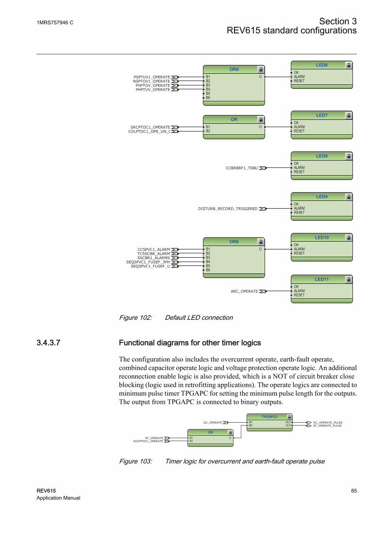
LED6OKALARMRESET
LED7OKALARMRESET
LED8OKALARMRESET
LED9OKALARMRESET
LED10OKALARMRESET
LED11OKALARMRESET
OR6B1B2B3B4B5B6
O
OR6B1B2B3B4B5B6
O
ORB1B2
O
CCBRBRF1_TRBU
COLPTOC1_OPR_UN_I
PSPTUV1_OPERATE
SRCPTOC1_OPERATE
NSPTOV1_OPERATE
SEQSPVC1_FUSEF_U
PHPTOV_OPERATEPHPTUV_OPERATE
SEQSPVC1_FUSEF_3PH
CCSPVC1_ALARMTCSSCBR_ALARMSSCBR1_ALARMS
ARC_OPERATE
DISTURB_RECORD_TRIGGERED
GUID-507BAA3A-B10F-4662-B2D1-689FD2166B8B V2 EN
Figure 102: Default LED connection
3.4.3.7 Functional diagrams for other timer logics
The configuration also includes the overcurrent operate, earth-fault operate,combined capacitor operate logic and voltage protection operate logic. An additionalreconnection enable logic is also provided, which is a NOT of circuit breaker closeblocking (logic used in retrofitting applications). The operate logics are connected tominimum pulse timer TPGAPC for setting the minimum pulse length for the outputs.The output from TPGAPC is connected to binary outputs.
TPGAPC2IN1IN2
OUT1OUT2
ORB1B2
O
OC_OPERATE_PULSEEF_OPERATE_PULSE
ROVPTOV1_OPERATE
OC_OPERATE
EF_OPERATE
GUID-0B01B564-9EDE-4321-AA9A-51EA6FED31E1 V1 EN
Figure 103: Timer logic for overcurrent and earth-fault operate pulse
1MRS757946 C Section 3REV615 standard configurations
REV615 85Application Manual

TPGAPC3IN1IN2
OUT1OUT2
OR6B1B2B3B4B5B6
O
OR6B1B2B3B4B5B6
O
CAPACITOR_PROT_OPERATE_PULSEVOLT_PROT_OPERATE_PULSE
COLPTOC1_OPR_OVLODCOLPTOC1_OPR_UN_I
CUBPTOC1_OPERATE
PSPTUV1_OPERATE
SRCPTOC1_OPERATE
NSPTOV1_OPERATEPHPTOV_OPERATEPHPTUV_OPERATE
GUID-1A9D5CB7-C895-43E6-BF69-2A7D21DF6645 V1 EN
Figure 104: Timer logic for capacitor protection and voltage protection operatepulse
NOTIN OUT RECONNECTION_ENABLECBXCBR1_BLK_CLOSE
GUID-930F13E7-4F13-4AB3-AE51-C3AE4FC0D2BD V1 EN
Figure 105: Reconnection enable logic
3.4.3.8 Other functions
The configuration includes few instances of multipurpose protection functionMAPGAPC, runtime counter for machines and devices MDSOPT and different typesof timers and control functions. These functions are not included in applicationconfiguration but they can be based on the system requirements.
Section 3 1MRS757946 CREV615 standard configurations
86 REV615Application Manual

Section 4 Requirements for measurementtransformers
4.1 Current transformers
4.1.1 Current transformer requirements for non-directionalovercurrent protection
For reliable and correct operation of the overcurrent protection, the CT has to bechosen carefully. The distortion of the secondary current of a saturated CT mayendanger the operation, selectivity, and co-ordination of protection. However, whenthe CT is correctly selected, a fast and reliable short circuit protection can be enabled.
The selection of a CT depends not only on the CT specifications but also on thenetwork fault current magnitude, desired protection objectives, and the actual CTburden. The protection settings of the protection relay should be defined in accordancewith the CT performance as well as other factors.
4.1.1.1 Current transformer accuracy class and accuracy limit factor
The rated accuracy limit factor (Fn) is the ratio of the rated accuracy limit primarycurrent to the rated primary current. For example, a protective current transformer oftype 5P10 has the accuracy class 5P and the accuracy limit factor 10. For protectivecurrent transformers, the accuracy class is designed by the highest permissiblepercentage composite error at the rated accuracy limit primary current prescribed forthe accuracy class concerned, followed by the letter "P" (meaning protection).
Table 21: Limits of errors according to IEC 60044-1 for protective current transformers
Accuracy class Current error atrated primarycurrent (%)
Phase displacement at rated primarycurrent
Composite error atrated accuracy limitprimary current (%)minutes centiradians
5P ±1 ±60 ±1.8 5
10P ±3 - - 10
The accuracy classes 5P and 10P are both suitable for non-directional overcurrentprotection. The 5P class provides a better accuracy. This should be noted also if thereare accuracy requirements for the metering functions (current metering, powermetering, and so on) of the protection relay.
The CT accuracy primary limit current describes the highest fault current magnitudeat which the CT fulfils the specified accuracy. Beyond this level, the secondary current
1MRS757946 C Section 4Requirements for measurement transformers
REV615 87Application Manual

of the CT is distorted and it might have severe effects on the performance of theprotection relay.
In practise, the actual accuracy limit factor (Fa) differs from the rated accuracy limitfactor (Fn) and is proportional to the ratio of the rated CT burden and the actual CTburden.
The actual accuracy limit factor is calculated using the formula:
F FS S
S Sa n
in n
in
≈ ×
+
+
A071141 V1 EN
Fn the accuracy limit factor with the nominal external burden Sn
Sin the internal secondary burden of the CT
S the actual external burden
4.1.1.2 Non-directional overcurrent protection
The current transformer selectionNon-directional overcurrent protection does not set high requirements on the accuracyclass or on the actual accuracy limit factor (Fa) of the CTs. It is, however,recommended to select a CT with Fa of at least 20.
The nominal primary current I1n should be chosen in such a way that the thermal anddynamic strength of the current measuring input of the protection relay is notexceeded. This is always fulfilled when
I1n > Ikmax / 100,
Ikmax is the highest fault current.
The saturation of the CT protects the measuring circuit and the current input of theprotection relay. For that reason, in practice, even a few times smaller nominalprimary current can be used than given by the formula.
Recommended start current settingsIf Ikmin is the lowest primary current at which the highest set overcurrent stage is tooperate, the start current should be set using the formula:
Current start value < 0.7 × (Ikmin / I1n)
I1n is the nominal primary current of the CT.
The factor 0.7 takes into account the protection relay inaccuracy, current transformererrors, and imperfections of the short circuit calculations.
Section 4 1MRS757946 CRequirements for measurement transformers
88 REV615Application Manual
The adequate performance of the CT should be checked when the setting of the highset stage overcurrent protection is defined. The operate time delay caused by the CTsaturation is typically small enough when the overcurrent setting is noticeably lowerthan Fa.
When defining the setting values for the low set stages, the saturation of the CT doesnot need to be taken into account and the start current setting is simply according to theformula.
Delay in operation caused by saturation of current transformersThe saturation of CT may cause a delayed protection relay operation. To ensure thetime selectivity, the delay must be taken into account when setting the operate timesof successive protection relays.
With definite time mode of operation, the saturation of CT may cause a delay that isas long as the time the constant of the DC component of the fault current, when thecurrent is only slightly higher than the starting current. This depends on the accuracylimit factor of the CT, on the remanence flux of the core of the CT, and on the operatetime setting.
With inverse time mode of operation, the delay should always be considered as beingas long as the time constant of the DC component.
With inverse time mode of operation and when the high-set stages are not used, the ACcomponent of the fault current should not saturate the CT less than 20 times thestarting current. Otherwise, the inverse operation time can be further prolonged.Therefore, the accuracy limit factor Fa should be chosen using the formula:
Fa > 20 × Current start value / I1n
The Current start value is the primary start current setting of the protection relay.
4.1.1.3 Example for non-directional overcurrent protection
The following figure describes a typical medium voltage feeder. The protection isimplemented as three-stage definite time non-directional overcurrent protection.
1MRS757946 C Section 4Requirements for measurement transformers
REV615 89Application Manual

A071142 V1 EN
Figure 106: Example of three-stage overcurrent protection
The maximum three-phase fault current is 41.7 kA and the minimum three-phase shortcircuit current is 22.8 kA. The actual accuracy limit factor of the CT is calculated tobe 59.
The start current setting for low-set stage (3I>) is selected to be about twice thenominal current of the cable. The operate time is selected so that it is selective with thenext protection relay (not visible in Figure 106). The settings for the high-set stage andinstantaneous stage are defined also so that grading is ensured with the downstreamprotection. In addition, the start current settings have to be defined so that theprotection relay operates with the minimum fault current and it does not operate withthe maximum load current. The settings for all three stages are as in Figure 106.
For the application point of view, the suitable setting for instantaneous stage (I>>>) inthis example is 3 500 A (5.83 × I2n). For the CT characteristics point of view, thecriteria given by the current transformer selection formula is fulfilled and also theprotection relay setting is considerably below the Fa. In this application, the CT ratedburden could have been selected much lower than 10 VA for economical reasons.
Section 4 1MRS757946 CRequirements for measurement transformers
90 REV615Application Manual

Section 5 IED physical connections
5.1 Inputs
5.1.1 Energizing inputs
5.1.1.1 Phase currents
The IED can also be used in single or two-phase applications byleaving one or two energizing inputs unoccupied. However, at leastterminals X120:7-8 must be connected.
Table 22: Phase current inputs included in configurations A and B
Terminal DescriptionX120:1-2 IL1 unb 1)
X120:3-4 IL2 unb 2)
X120:5-6 IL3 unb 2)
X120:7-8 IL1
X120:9-10 IL2
X120:11-12 IL3
1) Used only for HCUBPTOC1 and CUBPTOC12) Used only for HCUBPTOC1
5.1.1.2 Residual current
Table 23: Residual current input included in configurations A and B
Terminal DescriptionX120:13-14 Io
5.1.1.3 Phase voltages
Table 24: Phase voltage inputs included in configuration B
Terminal DescriptionX130:11-12 U1
X130:13-14 U2
X130:15-16 U3
1MRS757946 C Section 5IED physical connections
REV615 91Application Manual

5.1.1.4 Residual voltage
Table 25: Residual voltage input included in configurations A and B
Terminal DescriptionX130:9-10 UoB1)
X130:17-18 Uo
1) Used only for ROVPTOV2 and ROVPTOV3
5.1.2 Auxiliary supply voltage input
The auxiliary voltage of the protection relay is connected to terminals X100:1-2. AtDC supply, the positive lead is connected to terminal X100:1. The permitted auxiliaryvoltage range (AC/DC or DC) is marked on the top of the LHMI of the protectionrelay.
Table 26: Auxiliary voltage supply
Terminal DescriptionX100:1 + Input
X100:2 - Input
5.1.3 Binary inputs
The binary inputs can be used, for example, to generate a blocking signal, to unlatchoutput contacts, to trigger the disturbance recorder or for remote control of IEDsettings.
Binary inputs of slot X110 are optional with configurations A and B.
Table 27: Binary input terminals X110:1-13 with BIO0005 module
Terminal DescriptionX110:1 BI1, +
X110:2 BI1, -
X110:3 BI2, +
X110:4 BI2, -
X110:5 BI3, +
X110:6 BI3, -
X110:6 BI4, -
X110:7 BI4, +
X110:8 BI5, +
X110:9 BI5, -
X110:9 BI6, -
X110:10 BI6, +
X110:11 BI7, +
Table continues on next page
Section 5 1MRS757946 CIED physical connections
92 REV615Application Manual

Terminal DescriptionX110:12 BI7, -
X110:12 BI8, -
X110:13 BI8, +
Table 28: Binary input terminals X110:1-10 with BIO0007 module
Terminal DescriptionX110:1 BI1, +
X110:5 BI1, -
X110:2 BI2, +
X110:5 BI2, -
X110:3 BI3, +
X110:5 BI3, -
X110:4 BI4, +
X110:5 BI4, -
X110:6 BI5, +
X110:10 BI5, -
X110:7 BI6, +
X110:10 BI6, -
X110:8 BI7, +
X110:10 BI7, -
X110:9 BI8, +
X110:10 BI8, -
Optional binary inputs of slot X130 are available with configuration A.
Table 29: Optional binary input terminals X130:1-9 with BIO0006 module
Terminal DescriptionX130:1 BI1, +
X130:2 BI1, -
X130:2 BI2, -
X130:3 BI2, +
X130:4 BI3, +
X130:5 BI3, -
X130:5 BI4, -
X130:6 BI4, +
X130:7 BI5, +
X130:8 BI5, -
X130:8 BI6, -
X130:9 BI6, +
1MRS757946 C Section 5IED physical connections
REV615 93Application Manual

Optional binary inputs of slot X130 are available with configuration B.
Table 30: Optional binary input terminals X130:1-8 with AIM0006 module
Terminal DescriptionX130:1 BI1, +
X130:2 BI1, -
X130:3 BI2, +
X130:4 BI2, -
X130:5 BI3, +
X130:6 BI3, -
X130:7 BI4, +
X130:8 BI4, -
5.1.4 Optional light sensor inputs
If the IED is provided with the optional communication module with light sensorinputs, the pre-manufactured lens-sensor fibers are connected to inputs X13, X14 andX15. See the connection diagrams.For further information, see arc protection.
The IED is provided with connection sockets X13, X14 and X15 onlyif the optional communication module with light sensor inputs hasbeen installed. If the arc protection option is selected when ordering anIED, the light sensor inputs are included in the communicationmodule.
Table 31: Light sensor input connectors
Terminal DescriptionX13 Input Light sensor 1
X14 Input Light sensor 2
X15 Input Light sensor 3
5.1.5 RTD/mA inputs
It is possible to connect mA and RTD based measurement sensors to the IED if theIED is provided with optional RTD0001 module in standard configuration A and withAIM0003 module in standard configuration B.
Table 32: Optional RTD/mA inputs for standard configuration A
Terminal DescriptionX130:1 mA1 (AI1), +
X130:2 mA1 (AI1), -
X130:3 mA2 (AI2), +
Table continues on next page
Section 5 1MRS757946 CIED physical connections
94 REV615Application Manual

Terminal DescriptionX130:4 mA2 (AI2), -
X130:5 RTD1 (AI3), +
X130:6 RTD1 (AI3), -
X130:7 RTD2 (AI4), +
X130:8 RTD2 (AI4), -
X130:9 RTD3 (AI5), +
X130:10 RTD3 (AI5), -
X130:11 Common1)
X130:12 Common2)
X130:13 RTD4 (AI6), +
X130:14 RTD4 (AI6), -
X130:15 RTD5 (AI7), +
X130:16 RTD5 (AI7), -
X130:17 RTD6 (AI8), +
X130:18 RTD6 (AI8), -
1) Common ground for RTD channels 1-32) Common ground for RTD channels 4-6
Table 33: Optional RTD/mA inputs for standard configuration B
Terminal DescriptionX130:1 mA 1 (AI1), +
X130:2 mA 1 (AI1), -
X130:3 RTD1 (AI2), +
X130:4 RTD1 (AI2), -
X130:5 RTD1 (AI2), ground
X130:6 RTD2 (AI3), +
X130:7 RTD2 (AI3), -
X130:8 RTD2 (AI3), ground
5.2 Outputs
5.2.1 Outputs for tripping and controlling
Output contacts PO1, PO2, PO3 and PO4 are heavy-duty trip contacts capable ofcontrolling most circuit breakers.
1MRS757946 C Section 5IED physical connections
REV615 95Application Manual

Table 34: Output contacts
Terminal DescriptionX100:6 PO1, NO
X100:7 PO1, NO
X100:8 PO2, NO
X100:9 PO2, NO
X100:15 PO3, NO (TCS resistor)
X100:16 PO3, NO
X100:17 PO3, NO
X100:18 PO3 (TCS1 input), NO
X100:19 PO3 (TCS1 input), NO
X100:20 PO4, NO (TCS resistor)
X100:21 PO4, NO
X100:22 PO4, NO
X100:23 PO4 (TCS2 input), NO
X100:24 PO4 (TCS2 input), NO
5.2.2 Outputs for signalling
SO output contacts can be used for signalling on start and tripping of the IED.
Table 35: Output contacts X100:10-14
Terminal DescriptionX100:10 SO1, common
X100:11 SO1, NC
X100:12 SO1, NO
X100:13 SO2, NO
X100:14 SO2, NO
Table 36: Output contacts X110:14-24 with BIO0005
Terminal DescriptionX110:14 SO1, common
X110:15 SO1, NO
X110:16 SO1, NC
X110:17 SO2, common
X110:18 SO2, NO
X110:19 SO2, NC
X110:20 SO3, common
X110:21 SO3, NO
X110:22 SO3, NC
X110:23 SO4, common
X110:24 SO4, NO
Section 5 1MRS757946 CIED physical connections
96 REV615Application Manual
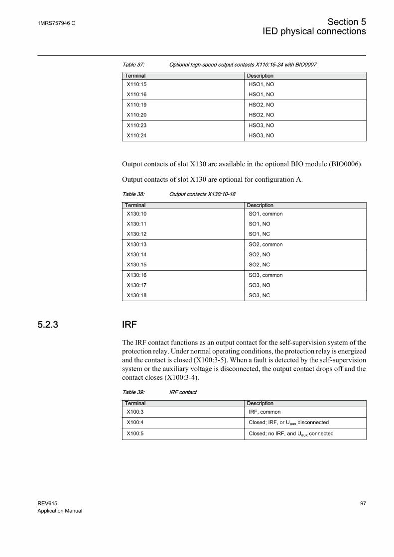
Table 37: Optional high-speed output contacts X110:15-24 with BIO0007
Terminal DescriptionX110:15 HSO1, NO
X110:16 HSO1, NO
X110:19 HSO2, NO
X110:20 HSO2, NO
X110:23 HSO3, NO
X110:24 HSO3, NO
Output contacts of slot X130 are available in the optional BIO module (BIO0006).
Output contacts of slot X130 are optional for configuration A.
Table 38: Output contacts X130:10-18
Terminal DescriptionX130:10 SO1, common
X130:11 SO1, NO
X130:12 SO1, NC
X130:13 SO2, common
X130:14 SO2, NO
X130:15 SO2, NC
X130:16 SO3, common
X130:17 SO3, NO
X130:18 SO3, NC
5.2.3 IRF
The IRF contact functions as an output contact for the self-supervision system of theprotection relay. Under normal operating conditions, the protection relay is energizedand the contact is closed (X100:3-5). When a fault is detected by the self-supervisionsystem or the auxiliary voltage is disconnected, the output contact drops off and thecontact closes (X100:3-4).
Table 39: IRF contact
Terminal DescriptionX100:3 IRF, common
X100:4 Closed; IRF, or Uaux disconnected
X100:5 Closed; no IRF, and Uaux connected
1MRS757946 C Section 5IED physical connections
REV615 97Application Manual

98

Section 6 Glossary
615 series Series of numerical protection and control relays forprotection and supervision applications of utilitysubstations, and industrial switchgear and equipment
AC Alternating currentAI Analog inputASCII American Standard Code for Information InterchangeBI Binary inputBIO Binary input and outputBO Binary outputCB Circuit breakerCT Current transformerDAN Doubly attached nodeDC 1. Direct current
2. Disconnector3. Double command
DNP3 A distributed network protocol originally developed byWestronic. The DNP3 Users Group has the ownershipof the protocol and assumes responsibility for itsevolution.
DPC Double-point controlEMC Electromagnetic compatibilityEthernet A standard for connecting a family of frame-based
computer networking technologies into a LANFIFO First in, first outFTP File transfer protocolFTPS FTP SecureGOOSE Generic Object-Oriented Substation EventHMI Human-machine interfaceHSO High-speed outputHSR High-availability seamless redundancyHTTPS Hypertext Transfer Protocol SecureI/O Input/output
1MRS757946 C Section 6Glossary
REV615 99Application Manual

IEC International Electrotechnical CommissionIEC 60870-5-103 1. Communication standard for protective equipment
2. A serial master/slave protocol for point-to-pointcommunication
IEC 61850 International standard for substation communicationand modeling
IEC 61850-8-1 A communication protocol based on the IEC 61850standard series
IEC 61850-9-2 A communication protocol based on the IEC 61850standard series
IEC 61850-9-2 LE Lite Edition of IEC 61850-9-2 offering process businterface
IED Intelligent electronic device (protection and controlrelay)
IEEE 1588 v2 Standard for a Precision Clock SynchronizationProtocol for networked measurement and controlsystems
IEEE 1686 Standard for Substation Intelligent Electronic Devices'(IEDs') Cyber Security Capabilities
IP address A set of four numbers between 0 and 255, separated byperiods. Each server connected to the Internet isassigned a unique IP address that specifies the locationfor the TCP/IP protocol.
IRIG-B Inter-Range Instrumentation Group's time code formatB
LAN Local area networkLCD Liquid crystal displayLE Light EditionLED Light-emitting diodeLHMI Local human-machine interfaceMAC Media access controlMCB Miniature circuit breakerMMS 1. Manufacturing message specification
2. Metering management systemModbus A serial communication protocol developed by the
Modicon company in 1979. Originally used forcommunication in PLCs and RTU devices.
Modbus TCP/IP Modbus RTU protocol which uses TCP/IP and Ethernetto carry data between devices
Section 6 1MRS757946 CGlossary
100 REV615Application Manual

NC Normally closedNO Normally openPCM600 Protection and Control IED ManagerPO Power outputPRP Parallel redundancy protocolPTP Precision Time ProtocolRIO600 Remote I/O unitRJ-45 Galvanic connector typeRSTP Rapid spanning tree protocolRTD Resistance temperature detectorRTU Remote terminal unitSAN Single attached nodeSLD Single-line diagramSMV Sampled measured valuesSNTP Simple Network Time ProtocolSO Signal outputSingle-line diagram Simplified notation for representing a three-phase
power system. Instead of representing each of threephases with a separate line or terminal, only oneconductor is represented.
TCS Trip-circuit supervisionVT Voltage transformerWAN Wide area networkWHMI Web human-machine interface
1MRS757946 C Section 6Glossary
REV615 101Application Manual

102

103


Contact us
ABB OyMedium Voltage Products,Distribution AutomationP.O. Box 699FI-65101 VAASA, FinlandPhone +358 10 22 11Fax +358 10 22 41094
www.abb.com/mediumvoltage
www.abb.com/substationautomation
ABB India Limited,Distribution AutomationManeja WorksVadodara-390013, IndiaPhone +91 265 6724402Fax +91 265 6724423
www.abb.com/mediumvoltage
www.abb.com/substationautomation
1MR
S75
7946
C©
Cop
yrig
ht 2
016
AB
B. A
ll rig
hts
rese
rved
.