canyon power plant afc - california energy commission · construction specifications as required by...
TRANSCRIPT

APPENDIX A
X:\Anaheim AFC\Appendix Cover Pages.doc 1
ENGINEERING DESIGN CRITERIA
APPENDIX A1
X:\Anaheim AFC\Appendix Cover Pages.doc 2
CIVIL ENGINEERING DESIGN CRITERIA
MACBABY:USERS:JENNIFER:DESKTOP:ANAHEIM AFC APPENDICES AND PRODUCTION:APPENDICES:APP A1 CIVIL ENGR 7 DEC 07.DOC A1-1
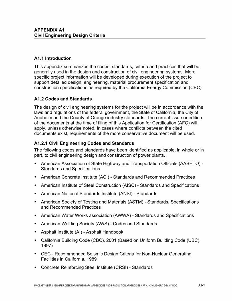
APPENDIX A1 Civil Engineering Design Criteria
A1.1 Introduction
This appendix summarizes the codes, standards, criteria and practices that will be generally used in the design and construction of civil engineering systems. More specific project information will be developed during execution of the project to support detailed design, engineering, material procurement specification and construction specifications as required by the California Energy Commission (CEC).
A1.2 Codes and Standards
The design of civil engineering systems for the project will be in accordance with the laws and regulations of the federal government, the State of California, the City of Anaheim and the County of Orange industry standards. The current issue or edition of the documents at the time of filing of this Application for Certification (AFC) will apply, unless otherwise noted. In cases where conflicts between the cited documents exist, requirements of the more conservative document will be used.
A1.2.1 Civil Engineering Codes and Standards The following codes and standards have been identified as applicable, in whole or in part, to civil engineering design and construction of power plants.
• American Association of State Highway and Transportation Officials (AASHTO) - Standards and Specifications
• American Concrete Institute (ACI) - Standards and Recommended Practices
• American Institute of Steel Construction (AISC) - Standards and Specifications
• American National Standards Institute (ANSI) - Standards
• American Society of Testing and Materials (ASTM) - Standards, Specifications and Recommended Practices
• American Water Works association (AWWA) - Standards and Specifications
• American Welding Society (AWS) - Codes and Standards
• Asphalt Institute (AI) - Asphalt Handbook
• California Building Code (CBC), 2001 (Based on Uniform Building Code (UBC), 1997)
• CEC - Recommended Seismic Design Criteria for Non-Nuclear Generating Facilities in California, 1989
• Concrete Reinforcing Steel Institute (CRSI) - Standards

MACBABY:USERS:JENNIFER:DESKTOP:ANAHEIM AFC APPENDICES AND PRODUCTION:APPENDICES:APP A1 CIVIL ENGR 7 DEC 07.DOC A1-2
• Factory Mutual (FM) - Standards
• National Fire Protection Association (NFPA) - Standards
• Steel Structures Painting Council (SSPC) - Standards and Specifications
• City of Anaheim - Standard Plans and Standard Specifications
• County of Orange Local Drainage Manual
• Orange County Hydrology Manual
• CalTrans Highway Design Manual, Specifications, and Standard Plans
A1.2.2 Engineering Geology Codes, Standards and Certifications Engineering geology activities will conform to the applicable federal, state and local laws, regulations, ordinances and industry codes and standards.
A1.2.2.1 Federal US Army Corps of Engineer’s Design Manual, Specs, and Standard Plans.
A1.2.2.2 State The Warren-Alquist Act, PRC, Section 25000 et seq. and the CEC Code of Regulations (CCR), Siting Regulations, Title 20 CCR, Chapter 2, require that Application for Certification (AFC) address the geologic and seismic aspects of the project.
The California Environmental Quality Act (CEQA), PRC 21000 et seq. and the CEQA Guidelines require that potentially significant effects, including geologic hazards, be identified and a determination made as to whether they can be substantially reduced.
A1.2.2.3 Local California State Planning Law, Government Code Section 65302, requires each city and county to adopt a general plan, consisting of nine mandatory elements, to guide its physical development. Section 65302(f) requires that a seismic safety element be included in the general plan.
The project development activities will require certification by a Professional Geotechnical Engineer and a Professional Engineering Geologist during and following construction, in accordance with the California Building Code CBC), Chapter 33 and Appendix Chapter 33. The Professional Geotechnical Engineer and/or the Professional Engineering Geologist will certify the placement of earthen fills and the adequacy of the site for structural improvements, as follows:
• Both the Professional Geotechnical Engineer and the Professional Engineer will address CBC Appendix Chapter 33, Sections 3309 (Grading Permits), 3312 (Cuts), 3313 (Fills), 3315 (Terraces), 3316 (Erosion Control), and 3318 (Final Report).

MACBABY:USERS:JENNIFER:DESKTOP:ANAHEIM AFC APPENDICES AND PRODUCTION:APPENDICES:APP A1 CIVIL ENGR 7 DEC 07.DOC A1-3
• The Professional Geotechnical Engineer will also address CBC Appendix Chapter 33, Sections 3314 (Setbacks) and 3315 (Terraces).
Additionally, the Professional Engineering Geologist will present findings and conclusions pursuant to PRC, Section 25523 (a) and (c); and 20 CCR, Section 1752 (b) and (c).
A1.2.3 Storm Drainage Codes, Standards and Certifications Storm drainage design activities will conform to the applicable federal, state and local laws, regulations, ordinances and industry codes and standards. The design of all storm drainage will be performed by, or under the direct supervision of a licensed civil engineer.
The following codes and standards have been identified as applicable, in whole or in part, to the storm drainage design of this power plant.
• City of Anaheim – Department of Public Works – Storm Drainage Manual for Public and Private Storm Drainage Facilities
• City of Anaheim – Department of Public Works – Subdivision Section – Grading Design Manual
• County of Orange Local Drainage Manual
• Orange County Hydrology Manual
A1.2.2.1 Federal All finish floors shall be higher than the 100-year flood plain elevation as established by the Federal Emergency Management Agency.
A1.2.2.2 State None are applicable.
A1.2.2.3 Local Both the City of Anaheim and County of Orange have specific requirements for the storm water management design that will be met by this project. All open and underground channels and storm drains with drainage areas less than 640 acres and tributary to the Santa Ana River watershed must be designed for the 25-year frequency storm event.
APPENDIX A2
X:\Anaheim AFC\Appendix Cover Pages.doc 3
STRUCTURAL ENGINEERING DESIGN CRITERIA

SAC/150038/020B.DOCA2.B-1 A2-1
APPENDIX A2 Structural Engineering Design Criteria
A2.1 Introduction
The purpose of this appendix is to summarize the codes and standards and standard design criteria and practices that will be used in the design and construction of the structural engineering portions of the project. These criteria form the basis of the design for the structural components and systems of the project. More specific design information will be developed during detailed design to support equipment procurement and construction specifications. Section A2.2.0 summarizes the applicable codes and standards and Section A2.3.0 includes the general criteria for natural phenomena, design loads, architectural features, concrete, steel, and seismic design. Section A2.4.0 describes the structural design methodology for structures and equipment. Section A2.5.0 describes the hazard mitigation for the project.
A2.2 Design Codes and Standards
The design and specification of work shall be in accordance with all applicable laws and regulations of the federal government, the state of California, and with the applicable local codes and ordinances. A summary of the codes and industry standards to be used in the design and construction follows.
• Specifications for materials will generally follow the standard specifications of the American Society for Testing and Materials (ASTM) and the American National Standards Institute (ANSI).
• Field and laboratory testing procedures for materials will follow standard ASTM specifications.
• Design and placement of structural concrete will follow the recommended practices and the latest version of the American Concrete Institute (ACI), the California Building Code, 2007 Edition (CBC 2007) based on the International Building Code (IBC 2006), the City of Anaheim Building Code, 2007 Edition (ABC 2007), and the Concrete Reinforcing Steel Institute (CRSI).
• Design, fabrication, and erection of structural steel will follow the recommended practices and the latest version of the American Institute of Steel Construction Code (AISC), CBC 2007, and ABC 2007.
• Steel components for metal wall panels and roof decking will conform to the American Iron and Steel Institute (AISI) Specification for the Design of Light Gage Cold-Formed Structural Members.
• Welding procedures and qualifications for welders will follow the recommended practices and codes of the American Welding Society (AWS).

SAC/150038/020B.DOC A2.-2
• Preparation of metal surfaces for coating systems will follow the specifications and standard practices of the Steel Structures Painting Council (SSPC), National Association for Corrosion Engineers (NACE), and the specific instructions of the coatings manufacturer.
• Fabrication and erection of grating will follow applicable standards of the National Association of Architectural Metals Manufacturers (NAAMM).
• Design and erection of masonry materials will follow the recommended practices and codes of the latest revision of the ACI Concrete Masonry Structures Design (ACI 530), California Building Code, 2007 Edition (CBC) and ABC 2007.
• Design will conform to the requirements of the Federal and California Occupational Safety and Health Administration (OSHA and CALOSHA).
• Design of roof coverings will conform to the requirements of the National Fire Protection Association (NFPA) and Factory Mutual (FM).
Other recognized standards will be used where required to serve as guidelines for the design, fabrication, and construction.
The following laws, ordinances, codes, and standards have been identified as applying to structural design and construction. In cases where conflicts between cited codes (or standards) exist, the requirements of the more conservative code will be met.
A2.2.1 Federal • Title 29 Code of Federal Regulations, Part 1910, Occupational Safety and Health
Standards.
• Walsh-Healy Public Contracts Act (P.L. 50-204.10).
A2.2.2 State • Business and Professions Code Section 6704, et seq.; Section 6730 and 6736.
Requires state registration to practice as a Civil Engineer or Structural Engineer in California.
• Labor Code Section 6500, et seq. requires a permit for construction of trenches or excavations 5 feet or deeper where personnel have to descend. This also applies to construction or demolition of any building, structure, false work, or scaffolding that is more than three stories high or equivalent.
• Title 24 California Code of Regulations (CCR). Adopts current edition of CBC as minimum legal building standards.
• State of California Department of Transportation, Standard Specifications.
• Title 8 CCR Sections 1500, et seq.; Sections 2300, et seq.; and Sections 3200, et seq. Describes general construction safety orders, industrial safety orders, and work safety requirements and procedures.

SAC/150038/020B.DOC A2.-3
• Regulations of the following state agencies as applicable.
− Department of Labor and Industry Regulations.
− Bureau of Fire Protection.
− Department of Public Health.
− Water and Power Resources.
• Title 8 CCR Section 450, et seq. and Section 750, et seq. Adapts American Society of Mechanical Engineers Boiler and Pressure Vessel Code (ASMEB and PVC) and other requirements for unfired and fired boilers.
A2.2.3 Industry Codes and Standards • California Energy Commission, “Recommended Seismic Design Criteria for Non-
Nuclear Power Generating Facilities in California”.
• International Conference of Building Officials, “California Building Code” (CBC), 2007 Edition.
• City of Anaheim Building Code 2007.
• Structural Engineers Association of California, “Recommended Lateral Force Requirements and Commentary”.
• Applied Technology Council, “Tentative Provision for the Development of Seismic Regulations for Buildings,” (ATC-3-06), Amended December 1982.
• American Institute of Steel Construction (AISC).
− Specification for Structural Steel Buildings-Allowable Stress Design and Plastic Design, 13th Edition, 2005.
− “Code of Standard Practice for Steel Buildings and Bridges.”
− “Allowable Stress Design Specifications for Structural Joints Using ASTM A325 or A490 Bolts.”
− Manual of Steel Construction Allowable Stress Design, 13th Edition.
• American Iron and Steel Institute (AISI) “North American Specification for the Design of Cold-Formed Steel Structural Members,” 2001. “2002 Edition Cold-Formed Steel Design Manual Parts I-VII.”
• American Welding Society (AWS) “Structural Welding Code-Steel Latest Edition” (AWS D1.1).
• American Concrete Institute (ACI).
− “Building Code Requirements for Reinforced Concrete” (ACI 318/318R-05).

SAC/150038/020B.DOC A2.-4
− “Code Requirements for Nuclear Safety Related Structures,” Appendix B (Steel Embedments only) (ACI 349-01), except that anchor bolts will be embedded to develop their yield strength.
− ACI 530-05 “Building Code Requirements for Concrete Masonry Structures”.
− ACI 212.3R-91--Chemical Admixtures for Concrete.
− ACI 302.IR-96--Guide for Concrete Floor and Slab Construction.
− ACI 350R-01--Environmental Engineering Concrete Structures
• Structural and Miscellaneous Steel.
− ASTM A569/A569M Specifications for Steel Carbon (0.15 maximum percent) Hot-Rolled Sheet and Strip, Commercial Quality.
− ASME/ANSI STS-1-1986--Steel stacks, except for circumferential stiffening which shall be in accordance with British Standard 4076--1978 and except that seismic design shall be in accordance with CBC 2001.
• American Society for Testing and Materials (ASTM). The current versions of the following codes and standards shall be included as a minimum.
− ASTM A36/A36M--Standard Specification for Carbon Structural Steel.
− ASTM A53--Specification for Pipe, Steel, Black and Hot-Dipped, Zinc Coated, Welded and Seamless.
− ASTM A276--Specification for Stainless Steel Bars and Shapes.
− ASTM A500--Specification for Cold-formed Welded and Seamless Carbon Steel Structural Tubing in Rounds and Shapes.
− ASTM B695--Specification for Coatings of Zinc Mechanically Deposited on Iron and Steel.
− ASTM A307--Specification for Carbon Steel Bolts and Studs.
− ASTM A123 —Specification for Zinc (Hot Dip Galvanized) Coatings on Iron and Steel Products.
− ASTM A153--Specification for Zinc Coating (Hot-Dip) on Iron and Steel Hardware.
− ASTM A82-A - Specification for Steel Wire, Plain, for Concrete Reinforcement.
− ASTM A185--Standard Specification for Steel Welded Wire Fabric, Plain, for Concrete Reinforcement.
− ASTM A 615/A615 M-Specification for Deformed and Plain Billet-Steel Bars for Concrete Reinforcement.
• Masonry Institute of America, “Reinforced Masonry Engineering Handbook.”

SAC/150038/020B.DOC A2.-5
• National Fire Protection Association Standards (NFPA).
• Steel Structures Painting Council Standards (SSPC).
• American Society of Nondestructive Testing (SNT-TC-1A).
• International Standard Organization (ISO) 3945-85 “Mechanical Vibration of Large Rotating Machines with Speed Range from 10 to 200 revs/sec—Measurement and Evaluation of Vibration Severity In Situ.”
The codes and industry standards used for design, fabrication, and construction will be the codes and industry standards, including all addenda, in effect as stated in equipment and construction purchase or contract documents. Where no other standard or code governs, the CBC will be used. In the event of conflict between referenced codes, standards, and design criteria, the more restrictive condition shall apply.
A2.3 Structural Design Criteria
A2.3.1 Natural Phenomena
A2.3.1.1 Datum The finished grade of the facility will be approximately 220ft. above MSL.
A2.3.1.2 Wind Speed The design wind speed will be 85 miles per hour based on CBC 2007 edition for a 50-year recurrence interval. This design wind speed will be used to determine wind loads for all structures as discussed in Section A2.3.2.3, Wind Loads.
A2.3.1.3 Temperature The design basis temperatures for Civil and structural systems will be as follows:
Maximum 110 Degrees, F
Minimum 29 Degrees, F
A2.3.1.4 Frost Penetration The site is located in an area free of frost penetration. Bottom elevation of all foundations for structures and equipment, however, will be maintained at a minimum of 1’-0” below the finished grade.
A2.3.1.5 Seismicity The plant site is located in Site Class D, as determined from CBC 2007 and Geotechnical Report dated October 10, 2007 by MACTEC Engineering and Consulting, Inc. “Report of Geotechnical Investigation: Proposed City of Anaheim 200 MW Peaking Power Plant”.

SAC/150038/020B.DOC A2.-6
A2.3.1.6 Snow The plant site is located in a zero ground snow load area, as determined from CBC 2007.
A2.3.2 Design Loads Design loads for all structures will be determined according to the criteria described below, unless the applicable building code requires more severe design conditions.
A2.3.2.1 Dead Loads Dead loads will consist of the weights of the structure and all equipment of a permanent or semi-permanent nature including tanks, bins, wall panels, partitions, roofing, piping, drains, electrical trays, bus ducts, and the contents of tanks and bins measured at full operating capacity. The contents of tanks and bins shall not be considered as effective in resisting column uplift due to wind forces but shall be considered effective for seismic forces.
A2.3.2.2 Live Loads Live loads will consist of uniform live loads and equipment live loads. Uniform live loads are assumed unit loads which are sufficient to provide for movable and transitory loads, such as the weight of people, portable equipment and tools, planking and small equipment, or parts which may be moved over or placed on floors during maintenance operations. These uniform live loads shall not be applied to floor areas which will be permanently occupied by equipment.
Equipment live loads are calculated loads based upon the actual weight and size of the equipment and parts to be placed on floors during dismantling and maintenance, or to be temporarily placed on or moved over floors during installation.
Uniform live loads will be in accordance with CBC 2007, but will not be less than the following:
a. Roofs 20 psf
All roof areas will be designed for wind loads as indicated in Subsection A2.3.2.3, Wind Loads. Ponding loading effect due to roof deck and framing deflections will be investigated in accordance with AISC Specification Article K2. All roof areas will be designed for a minimum of 20 psf live load in addition to calculated dead loads.
b. Floors and Platforms (Steel grating and checkered plate) 100 psf
In addition, a uniform load of 50 psf will be used to account for piping and cable tray, except where the piping and cable tray loads exceed 50 psf, the actual loads will be used. Pipe hanger loads for the major piping systems will be specifically determined and located. Piping expansion and dynamic loads will be considered on an individual basis for their effect on the structural systems. Loads imposed on perimeter beams around pipe chase areas will also be considered on an individual basis.
c. Floors (Elevated Concrete Floors) 125 psf

SAC/150038/020B.DOC A2.-7
In addition, elevated concrete slabs will be designed to support an alternate concentrated load of 3 kips in lieu of the uniform loads, whichever governs. The concentrated load will be treated as a uniformly distributed load acting over an area of 2.5 square feet, and will be located in a manner to produce the maximum stress conditions in the slab.
d. Control Room Floor 150 psf
e. Stairs, Landings and Walkways 100 psf
In addition, a concentrated load of 2 kips will be applied concurrently to the supporting beams for the walkways to maximize the stresses in the members, but the reactions from the concentrated loads will not be carried to the columns.
f. Pipe Racks 100 psf
Where the piping and cable tray loads exceed the design uniform load, the actual loads will be used. In addition, a concentrated load of 15 kips will be applied concurrently to the supporting beams for the walkways to maximize the stresses in the members, but the reactions from the concentrated loads will not be carried to the columns.
g. Hand Railings
Hand railings will be designed for either a uniform horizontal force of 50 plf applied simultaneously with a uniform vertical live load of 100 plf or a 200 pound concentrated load applied at any point and in any direction, whichever governs.
h. Slabs on Grade 250 psf
Consideration will be given to designing appropriate areas of the ground floor for support of heavy equipment such as construction and maintenance cranes.
i. Truck Loading Surcharge Adjacent to Structures 250 psf
j. Truck Support Structures AASHTO-HS-20-44
k. Special Loading Conditions Actual loadings
Laydown loads from equipment components during maintenance and floor areas where trucks, forklifts or other transports will have access, will be considered in the design live load.
Live loads may be reduced in accordance with the provisions of CBC.
Posting of the floor load capacity signs for all roofs, elevated floors, platforms and walkways will be in compliance with the OSHA Occupational Safety and Health Standard, Walking and Working Surfaces, Subpart D. Floor load capacity for slabs on grade will not be posted.
A2.3.2.3 Wind Loads Wind loads for all structures will be based on CBC 2007. Basic wind speed shall be 85 miles per hour and wind stagnation pressure (qs) of 20.5 psf. A step function of

SAC/150038/020B.DOC A2.-8
pressure with height under Exposure C conditions will be used. The Importance Factor shall equal 1.15. Height brackets and velocity pressures will be as follows.
Height Aboveground Feet
Velocity Pressure pounds-force per square foot
Grade to 20 21.7 20 to 40 24.0 40 to 60 27.4 60 to 100 30.6 100 to 160 33.7 160 to 200 35.3
The above velocity pressures are average values for the indicated height brackets. The design wind pressures will be determined by multiplying the velocity pressures by the appropriate pressure coefficients given in CBC.
If wind design governs, the detailing requirements and limitations in the CBC 2007 seismic provisions will also be followed.
A2.3.2.4 Steel Stack The steel stack and supports shall be capable of enduring specified normal and abnormal design operating conditions in combination with high wind or seismic event for the design life of the facility. Effects of wind will include along-wind and across-wind response. The design will address the design considerations, meet the requirements, and utilize the design methods of Steel Stacks, ASME/ANSI STS-1-1986, and AISC Manual of Steel Construction Allowable Stress Design, Thirteenth Edition, except that increased allowable stresses for wind will not be used. Design values for yield strength and modulus of elasticity of the stack material will depend on the composition of the material and the maximum temperature of the metal at design operating conditions, and will be as prescribed by the ASME Pressure Vessel Code, Section VIII, Division 2, Part AM. Seismic loads shall be in accordance with CBC 2007.
A2.3.2.5 Seismic Loads Seismic loads will be determined in accordance with the requirements specified in Section A2.3.6, Seismic Design Criteria.
A2.3.2.6 Construction Loads The integrity of the structures will be maintained without use of temporary framing struts or ties and cable bracing insofar as possible. However, construction or crane access considerations may dictate the use of temporary structural systems.
A2.3.2.7 Earth Pressures Earth pressures will be in accordance with the recommendations contained in the project-specific “Final Geotechnical Investigation and Foundation Report”.

SAC/150038/020B.DOC A2.-9
A2.3.2.8 Groundwater Pressures Hydrostatic pressures due to groundwater or temporary water loads will be considered.
A2.3.2.9 Special Considerations for Structures and Loads During Construction For temporary structures, or permanent structures left temporarily incomplete to facilitate equipment installations, or temporary loads imposed on permanent structures during construction, the allowable stresses may be increased by 33 percent.
Structural backfill may be placed against walls, retaining walls, and similar structures when the concrete strength attains 80 percent of the design compressive strength (f’c), as determined by sample cylinder tests. Restrictions on structural backfill, if any, will be shown on the engineering design drawings.
Metal decking used as forms for elevated concrete slabs will be evaluated to adequately support the weight of concrete plus a uniform construction load of 50 psf, without an increase in allowable stresses.
A2.3.2.10 Load Combinations At a minimum, the following load combinations will be considered. Applicable CBC 2007 prescribed load combinations will also be considered.
• Dead load
• Dead load plus live load plus all loads associated with normal operation of the equipment, e.g., temperature and pressure loads, piping loads, normal torque loads, impact loads, etc.
• Dead load plus live load plus all loads associated with normal operation plus wind load
• Dead load plus live load plus all loads associated with normal operation plus seismic load
• Dead load plus construction loads
• Dead load plus live load plus emergency loads
• Dead load plus wind load
• Dead load plus seismic load
Every building component shall be provided with the strength adequate to resist the most critical effect resulting from the following combination of loads.
• Dead plus floor live plus roof live • Dead plus floor live plus wind • Dead plus floor live plus seismic • Dead plus floor live plus wind plus roof live/2 • Dead plus floor live plus roof live plus wind/2

SAC/150038/020B.DOC A2.-10
• Dead plus floor live plus roof live plus seismic
Note: Use live load only where required by CBC 2007 in combination with seismic.
A2.3.2.11 Allowable Stresses Each load combination shall not exceed the allowable stress permitted by the appropriate code for that combination.
A2.3.2.11.1 Concrete Structures For reinforced concrete structures and equipment supports, using the strength method, the load factors and load combinations will be in accordance with CBC and the ACI-05.
A2.3.2.11.2 Steel Structures The required strength (S) based on the elastic design methods and the allowable stress design as defined in 2005, 13th Edition of the AISC Specification for the Design, Fabrication, and Erection of Structural Steel for Buildings.
Frame members and connections will conform to the additional requirements of CBC.
A2.3.3 Architecture General design criteria for the architectural systems are as follows. A2.3.3.1 Architecture—Engineered Buildings General design criteria for materials and installation of architectural systems or components will be as follows.
• Interior Walls. Where durability is required, interior walls may be constructed of concrete block masonry, structurally designed and reinforced as required. In offices, shops, etc., metal studs with gypsum board will usually be used to form interior partitions. Insulation for sound control will be used where required by design.
• Fire Exits. Fire exits will be provided at outside walls as required by code. Exit signs will be provided. Fire doors will bear an Underwriters’ Laboratories certification level for class of opening and rating for door, frame, and hardware. Doors will conform to wood or hollow metal door requirements and have fillers adequate to meet the fire rating.
• Large Access Exterior Doors. Large access exterior doors will be rolling steel type with weather seals and wind locks. Components will be formed from galvanized steel, factory primed, and field painted. Doors will be motor-operated with override manual operation.
• Painting. Exterior steel material that is not galvanized or factory finished will be painted. Painted color will match or harmonize with the color of the exterior face of the wall panels.
• Color Schemes. Color schemes will be selected for overall compatibility.

SAC/150038/020B.DOC A2.-11
A2.3.3.2 Architecture—Prefabricated Metal Buildings Prefabricated metal buildings (packaged to include exterior doors, wall louvers, windows, and related enclosure components) will be furnished as follows.
• Building Enclosure. Building enclosures will be of manufacturer’s standard modular rigid frame construction with tapered or uniform depth rafters rigidly connected at ends to pinned-base tapered or uniform depth columns. Purlins and girts will be cold-formed “C” or “Z” sections conforming to “Specifications for Design of Cold-Formed Steel Structural Members” of American Iron and Steel Institute. All other members will be of ASTM A36 hot rolled shapes conforming to “Specification for Design, Fabrication and Erection of Structural Steel for Buildings” of American Institute of Steel Construction. Roof slopes will be approximately 1-inch rise per 12 inches of run. Metal roof coverings will be of prefinished standing seam panels of 24-gauge minimum.
• Steel. Cold-formed components will conform to ASTMA570, Grade E, 42,000 psi minimum yield for material thicknesses equal to or less than 0.23 inch, or to ASTMA375, 50,000 pounds per square inch (psi) minimum yield for high tensile strength purlin or girt sections with material thicknesses equal to or less than 0.23 inch. Roof covering and wall covering will conform to ASTM A446, Grade A, galvanized 33,000 psi minimum yield. All cold-formed components will be manufactured by precision roll or break forming.
A2.3.4 Concrete Reinforced concrete structures will be designed in accordance with CBC 2007 and ACI 318-05, Building Code Requirements for Reinforced Concrete.
A2.3.4.1 Materials The materials described below will be specified and used as a basis for design.
• Reinforcing Steel. Reinforcing steel shall meet the requirements of ASTM A615 Grade-60. Welded wire fabric for concrete will conform to ASTM A 185.
• Cement. Cement used in all concrete mixes will be portland cement meeting the requirements of ASTM C150.
• Aggregates. Fine aggregates will be clean natural sand. Coarse aggregates will be crushed gravel or stone. All aggregates shall meet the requirements of ASTM C33.
• Admixtures. Plasticizers and retarders will be used to control setting time and to obtain optimum workability. Air entrainment of 4 to 6 percent by volume will be used in all concrete mixes. Calcium chloride will not be permitted. Interior slabs to be trowel finished may use less air entrainment.
• Water. Clean water of potable quality shall be used in all concrete.
SAC/150038/020B.DOC A2.-12
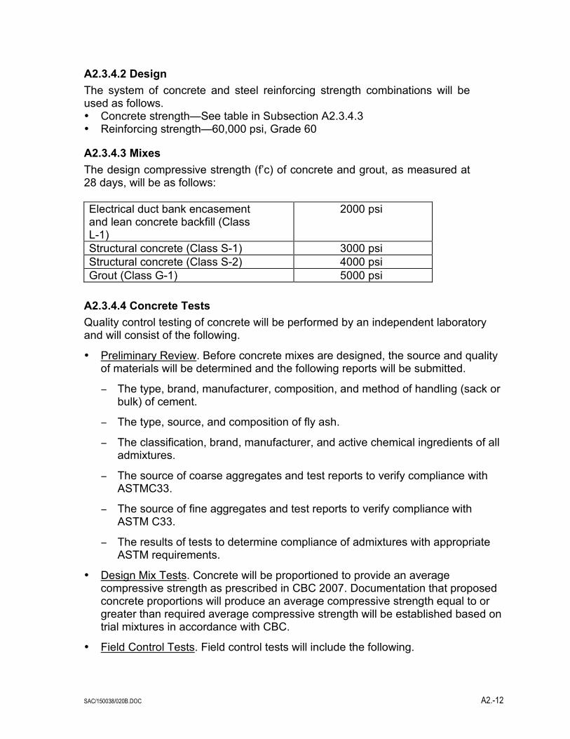
A2.3.4.2 Design The system of concrete and steel reinforcing strength combinations will be used as follows. • Concrete strength—See table in Subsection A2.3.4.3 • Reinforcing strength—60,000 psi, Grade 60
A2.3.4.3 Mixes The design compressive strength (f’c) of concrete and grout, as measured at 28 days, will be as follows: Electrical duct bank encasement and lean concrete backfill (Class L-1)
2000 psi
Structural concrete (Class S-1) 3000 psi Structural concrete (Class S-2) 4000 psi Grout (Class G-1) 5000 psi
A2.3.4.4 Concrete Tests Quality control testing of concrete will be performed by an independent laboratory and will consist of the following.
• Preliminary Review. Before concrete mixes are designed, the source and quality of materials will be determined and the following reports will be submitted.
− The type, brand, manufacturer, composition, and method of handling (sack or bulk) of cement.
− The type, source, and composition of fly ash.
− The classification, brand, manufacturer, and active chemical ingredients of all admixtures.
− The source of coarse aggregates and test reports to verify compliance with ASTMC33.
− The source of fine aggregates and test reports to verify compliance with ASTM C33.
− The results of tests to determine compliance of admixtures with appropriate ASTM requirements.
• Design Mix Tests. Concrete will be proportioned to provide an average compressive strength as prescribed in CBC 2007. Documentation that proposed concrete proportions will produce an average compressive strength equal to or greater than required average compressive strength will be established based on trial mixtures in accordance with CBC.
• Field Control Tests. Field control tests will include the following.

SAC/150038/020B.DOC A2.-13
− Aggregate gradation. Each 500 tons of fine aggregate and each 1,000 tons of coarse aggregate will be sampled and tested in accordance with ASTM D75 and C136.
− Slump. A slump test will be made from each of the first three batches mixed each day. An additional test will be made for each 50 cubic yards placed in any one day.
− Air content. An air content test will be made from one of the first three batches mixed each day and from each batch of concrete from which compression test cylinders are made. Air content tests will be in accordance with ASTM C231.
− Compression tests. One set of four concrete test cylinders will be made each day from each class of concrete being placed. Additional sets will be made depending on the amount of concrete placed each day. For each additional 100 cubic yards of each class, or major fraction thereof, placed in any one day, four additional sets of cylinders will be made. One cylinder of each set will be tested at an age of seven days, two cylinders of each set will be tested at 28 days, and one cylinder shall be stored until otherwise directed. Compression tests will be in accordance with ASTMC39.
A2.3.4.5 Reinforcing Steel Test Mill test reports certifying that reinforcing steel is in accordance with ASTM and project specifications will be required.
A2.3.5 Steel and Other Metals
A2.3.5.1 Structural Steel Steel framed structures will be designed in accordance with the CBC 2007 and the AISC Specification for the Structural Steel Building, Allowable Stress Design and Plastic Design, 13th Edition, 2005. In addition, steel framed structures will be designed in accordance with the criteria discussed in the following subsections.
A2.3.5.1.1 Materials Structural steel shapes, plates, and appurtenances for general use will conform to ASTM A36 or A 572. Structural steel required for heavy framing members may consider the use of ASTM A441. Structural steel required for tubes will conform to ASTM A500, Grade B. Connection bolts will conform to ASTM A325. Connections will conform to AISC Specification for Structural Joints. Welding electrodes will be as specified by the AWS. All structural steel will be shop primed after fabrication. Exterior structural steel may be hot dipped galvanized in lieu of prime painted.
A2.3.5.1.2 Tests Mill test reports or reports of tests made by the fabricator will be required certifying that all material is in conformance with the applicable ASTM specification. In addition, the fabricator will provide an affidavit stating that all steel specified has been provided at yield stresses in accordance with the drawings and the specification.
SAC/150038/020B.DOC A2.-14
A2.3.5.1.3 Design All steel framed structures will be designed as “rigid frame” (AISC Specification Type 1) or “simple” space frames (AISC Specification Type 2), utilizing single span beam systems, vertical diagonal bracing at main column lines, and horizontal bracing at the roof and major floor levels. The use of Type 1 rigid frames will generally be limited to one-story, open garage, warehouse or shed-type structures, or to prefabricated metal buildings.
Suspended concrete slabs will be considered as providing horizontal stability by diaphragm action after setup and curing. Deflections of the support steel will be controlled to prohibit “ponding” of the fresh concrete as it is placed. Metal roof decks attached with welding washers or fasteners may be considered to provide a structure with lateral force diaphragm action. Grating floors will not be considered as providing horizontal rigidity.
Connections will be in accordance with AISC standard connection design for field bolted connections. Connections will be designed with bolts for bearing type joints with threads in shear plane except where connections are required to be slip-critical. Larger diameter bolts may be used to develop larger capacity connections or elsewhere as determined by the engineer.
A2.3.6 Seismic Design Criteria This section provides the general criteria and procedures that will be used for seismic design of structures, equipment, and components.
The project site is located in Site Class D according to the California Building Code, 2007 edition. The seismic performance objectives for this facility are as follows.
• Resist minor levels of earthquake ground motion without damage.
• Resist moderate levels of earthquake ground motion without structural damage, but possibly experience some nonstructural damage.
• Resist major levels of earthquake ground motion without collapse, but possibly with some structural as well as nonstructural damage.
To achieve these objectives and to meet the requirements of the CEC and local codes, the facility will be designed in accordance with the 2007 edition of the California Building Code. All structures, equipment internals, and components will be separated from adjoining structures.
A2..3.6.1 Buildings and Structures The seismic class used for this site will be Class D as determined from CBC 2007 using an Importance Factor of 1.25. Seismic loading will be used in the design of structures only when it is greater than the computed wind loads.
Non-building structures are to be designed in accordance with CBC 2007. These are typically regular structures as defined in the CBC, so the static lateral force procedure will be applicable. In the event that dynamic analysis will be required

SAC/150038/020B.DOC A2.-15
based on discussions with the CBO, the affected structures will be evaluated in accordance with the requirements of the CBC.
Lateral forces on elements of structures and nonstructural components will be determined from the CBC requirement for equipment supported laterally at or below grade.
Steel framed structures will comply with the requirements of CBC.
Water storage tanks will meet the seismic design requirements of AWWA D100, Section 13, and CBC.
A2.4 Structural Design Methodology
This section describes the structural aspects of the design of the proposed facility. Each major structural component of the plant is addressed by defining the design criteria and analytical techniques that will be employed.
A2.4.1 Structures
A2.4.1.1 Combustion Turbine Foundations The combustion turbine foundations will be designed to support the turbine and generator components.
The foundation will be designed to resist the loadings furnished by the manufacturer and will be constructed of reinforced concrete.
A2.4.1.1.1 Foundation Loads Foundation loads will be furnished by the combustion turbine manufacturer and will be superimposed with loads for the foundation itself. Typical loading data supplied by the manufacturer include the following.
• Dead loads • Live loads • Wind loads from project specific criteria • Seismic loads from project specific criteria • Hydrostatic loads • Temperature and pressure loads • Dynamic operating loads • Emergency loads such as turbine accident loads
A2.4.1.1.2 Induced Forces The combustion turbine and associated equipment will be securely anchored to the foundation using cast-in-place steel anchor bolts or sleeved through-bolts designed to resist the equipment forces.
A2.4.1.1.3 Structural Criteria The foundation will be designed and constructed as a monolithic reinforced concrete structure using the criteria from Section A2.3.4, Concrete.

SAC/150038/020B.DOC A2.-16
The foundation design will address the following considerations:
• Soil bearing capacities and earth pressures • Pile capacities • Allowable settlements • Soil liquefaction potential • Equipment, structure, and environmental loads • Natural frequencies of rotating equipment • Access and maintenance • Equipment performance criteria • Dynamic effects of the rotating machinery
Environmental loading will be determined in accordance with, Section A2.3.1 Natural Phenomena. Wind loads will be determined using the velocity pressures specified in Subsection A2.3.2.3 Wind Loads.
Seismic loading to the foundation from the combustion turbine will be calculated using equivalent lateral forces applied at the center-of-gravity of the equipment in accordance with the criteria specified in Section A2.3.6 Seismic Design Criteria for rigid equipment.
Load combinations and their respective strength factors for the foundation design will be as indicated in Subsection A2.3.2.10 Load Combinations and Subsection A2.3.2.11 Allowable Stresses.
A2.4.1.1.4 Analytical Techniques The combustion turbine foundation will be designed using static analysis techniques assuming a pile supported rigid mat. The mat will be sized such that the allowable settlement and bearing pressure/pile capacity criteria developed from a detailed subsurface investigation will not be exceeded. The foundation will be analyzed as a combined footing assuming a linear vertical pressure distribution that is taken by the pile group. Pile loads shall be checked locally. The mat will be proportioned such that the resultant of the pile loads coincides as nearly as possible with the resultant of the vertical loading. The mat shall be reinforced to act as a pile cap spanning between piles. The minimum factors of safety against overturning and sliding will be 1.5 and 1.1, respectively. The factor of safety on the pile shall be determined by the geotechnical engineer.
The combustion turbine foundation will be checked for dynamic response of the operating combustion turbine. Manual calculations and simple computer models based on the fundamental principles of dynamic behavior of structures will be used to determine the natural frequencies of the support system. Where soil-structure interaction effects are important, low strain soil properties will be used to calculate soil springs using the procedures from Vibrations of Soils and Foundation by Richard, Hall, and Woods or a similar procedure. The concrete foundation will be analyzed as a rigid body on soil springs with the equipment modeled as a rigid mass located at its center of gravity and rigidly attached to the foundation. The foundation will be proportioned such that the principal natural frequencies will be at least 10 -percent removed from the equipment operating speed.

SAC/150038/020B.DOC A2.-17
Should the resulting foundation design prove to be uneconomical, the dynamic behavior of the foundation will be evaluated and compared to ISO 3945 Criteria for Vibration Severity. The resultant vibration level will be within the “Good” range of this standard.
A procedure for the dynamic analysis of large fan foundations supported by soil or piers, may be used to evaluate the dynamic behavior of the turbine foundations.
A2.4.1.2 Exhaust Duct and CO/SCR Foundation The exhaust duct and CO/SCR foundation will be designed to support the exhaust duct and CO/SCR catalyst structures and associated equipment.
The foundation will be designed to resist the loadings furnished by the manufacturer and will be constructed of reinforced concrete.
A2.4.1.2.1 Foundation Loads Foundation loads will be furnished by the exhaust duct manufacturer and will be superimposed with loads for the foundation itself. Typical loading data supplied by the manufacturer include the following:
• Dead loads • Live loads • Wind loads • Seismic loads • Hydrostatic loads • Temperature and pressure loads
The exhaust duct and CO/SCR foundation will be designed to resist a superimposed uniform live load of 250 psf over the area not otherwise occupied by equipment.
A2.4.1.2.2 Induced Forces The exhaust duct and CO/SCR and associated equipment will be securely anchored to the foundation using cast-in-place steel anchor bolts designed to resist the equipment forces.
A2.4.1.2.3 Structural Criteria The foundation will be designed and constructed as a monolithic reinforced concrete structure using the criteria from Section A2.3.4 Concrete. Refer to the soils report titled, “Report of Geotechnical Investigation: Proposed City of Anaheim 200MW Peaking Power Plant”, by MACTEC Inc. dated October 10, 2007 for the recommended foundation design procedure.
The foundation design will address the following considerations:

SAC/150038/020B.DOC A2.-18
• Soil bearing capacities and earth pressures • Pile capacities • Allowable settlements • Soil liquefaction potential • Equipment, structure, and environmental loads • Access and maintenance • Equipment performance criteria
Environmental loading will be determined in accordance with Section A2.3.1 Natural Phenomena. Wind loads will be determined using the velocity pressures specified in Subsection A2.3.2.3 Wind Loads.
Seismic loading to the foundation will be supplied by the exhaust duct manufacturer and will reflect the structural system used by the exhaust duct to resist lateral loading.
Load combinations and their respective allowable strengths will be as indicated in Subsection A2.3.2.10 Load Combinations and Subsection A2.3.2.11 Allowable Stresses.
A2.4.1.2.4 Analytical Techniques The exhaust duct and CO/SCR foundation will be designed using CBC 2007.
A2.4.1.3 Stack and Foundation The stacks will be carbon steel stacks supported on a reinforced concrete mat foundation. The height of the stacks will be approximately 85 feet and each will be 12 feet in diameter.
A2.4.1.3.1 Foundation Loads Foundation loads will be determined using project specific design criteria.
The design of the stack and foundation will include the following loads:
• Dead loads • Live loads • Wind loads • Seismic loads • Temperature and pressure loads
Foundation loading magnitudes cannot be determined until specific stack design is completed.
A2.4.1.3.2 Induced Forces The stack will be securely anchored to the foundation using cast-in-place steel anchor bolts designed to resist the foundation and stack induced forces.
A2.4.1.3.3 Structural System The steel stack will resist lateral loading as a fixed base cantilevered structure.

SAC/150038/020B.DOC A2.-19
A2.4.1.3.4 Structural Criteria The predominate forces acting on the stack will result from wind or seismic loading. The stack will be designed as indicated in Appendix A2., Subsection A2.3.2.4 Steel Stacks.
Seismic loads will be determined in accordance with CBC Non-building Structures. The fundamental period will be determined using CBC equations and will be calculated by both considering and ignoring the structural contribution of any lining material. The lower period will be used in the development of the seismic forces.
The allowable longitudinal stress, F, for the design of the stack shell will be determined from the following equations from ASME/ANSI STS-1-1986.
F = 1/8 Et/r/FS for t/r < 8Fp/E F = [Fy - Ks (Fy - Fp)] / FS for t/r > 8Fp/E < 20Fy/E F = Fy/FS for t/r > 20Fy/E where
E = Steel modulus of elasticity, t = Shell plate thickness with corrosion allowance, r = Shell radius, FS = Factor of safety equal to 1.5, Fy = Steel yield stress, and Fp = Steel proportional limit equal to 0.70 Fy.
Ks
Fy
E
t
r
Fy
E
Fp
E
=
!
!
"
#
$$$$
%
&
''''
20
20 8
2
The minimum shell thickness will be 1/4-inch plus 1/16-inch corrosion allowance. The corrosion allowance will be considered in the generation of seismic loads but not in the resistance to seismic or wind loads. Allowable stresses for stiffeners, platform members, and other details will be in accordance with the American Institute of Steel Construction Allowable Stress Design, 13th Edition. Allowable stresses for the shell will not be increased for wind or seismic loadings.
The stack will likely be supported using an octagonal, circular or square shaped reinforced mat footing. The foundation will be designed and constructed as a monolithic reinforced concrete structure using the criteria from Appendix G and Appendix B, Section B3.4 Concrete. The foundation system will likely be a rigid mat or mat supported on piles or drilled caissons could be used. Final foundation system selection will be by the project structural engineers.
The foundation design will address the following considerations.

SAC/150038/020B.DOC A2.-20
• Soil bearing capacities and earth pressures • Pile capacities • Allowable settlements • Soil liquefaction potential • Structure and environmental loads
Load combinations and their respective allowable strengths will be as indicated in Subsection A2.3.2.10 Load Combinations and Subsection A2.3.2.11 Allowable Stresses.
A2.4.1.3.5 Analytical Techniques Moments, shears, and axial forces will be calculated using static analysis procedures on a cantilevered member. Longitudinal stresses resulting from axial loads and flexure will be combined and compared to a single allowable stress.
The stack foundation will be designed using static analysis techniques, assuming a rigid mat. The mat will be sized such that the allowable settlement and bearing pressure criteria developed from a detailed subsurface investigation will not be exceeded. The foundation will be analyzed assuming a linear soil pressure distribution. The mat will be proportioned to resist the vertical gravity loads concurrent with the controlling lateral loads while maintaining a minimum 2.5 factor of safety against overturning. The factor of safety against sliding will be a minimum of 1.5.
A2.4.1.4 Buildings The various plant site buildings will provide support, enclosure, protection, and access to the systems contained within its boundaries.
A2.4.1.4.1 Foundation Loads Foundation loads will be determined from the analysis and design of the superstructure and from the support of the equipment contained within the structure. The following loads will be considered.
• Dead loads • Live loads • Equipment and piping loads • Wind loads • Seismic loads
A2.4.1.4.2 Induced Forces Each building and associated major equipment will be securely anchored to the foundation using cast-in-place steel anchor bolts designed to resist any induced forces.
A2.4.1.4.3 Structural System The buildings will be designed as AISC Type 1 rigid frames or as Type 2 simple braced frame. For the purpose of resisting seismic lateral loads, the structure will be classified as a regular structure with a concentric braced frame, ordinary moment

SAC/150038/020B.DOC A2.-21
resisting frame, or special moment resisting frame in accordance with the definitions of the California Building Code.
A2.4.1.4.4 Structural Criteria The building steel frames will be designed and constructed using the materials and criteria set forth in Section A2.3.5 Steel and Other Metals.
Environmental loading will be determined in accordance with Section A2.3.1 Natural Phenomena. Wind loads will be determined using the velocity pressures specified in Subsection A2.3.2.3 Wind Loads.
Seismic loading for the buildings will be calculated using equivalent lateral forces applied to the structure in accordance with the procedures of CBC.
The building foundations will be designed and constructed using reinforced concrete according to the criteria set forth in Section A2.3.4 Concrete. The foundation system will likely be comprised of a pile supported rigid mat. Foundation types will be controlled by depth of bedrock at specific locations and will be verified by the project geotechnical investigation.
The foundation design will address the following considerations.
• Soil bearing capacities and earth pressures • Allowable settlements • Soil liquefaction potential • Equipment, structure, and environmental loads • Access and maintenance • Equipment performance criteria
Load combinations and their respective allowable stresses will be as indicated in Subsection A2.3.2.10 Load Combinations and Subsection A2.3.2.11 Allowable Stresses.
A2.4.1.4.5 Analytical Techniques The building foundations will be designed using static analysis techniques assuming a pile supported rigid mat or mat foundations. The mat will be sized such that the allowable settlement and bearing pressure/pile capacity criteria developed from a detailed subsurface investigation will not be exceeded assuming a linear soil pressure distribution. The mat will be proportioned such that the resultant of the pile group loading coincides as nearly as possible with the resultant of the vertical loading. The minimum factors of safety against overturning and sliding will be 1.5 and 1.1, respectively.
A2.4.1.5 Gas Compressor Foundations The gas compressor foundations will be designed to support the gas compressor and its components.
The foundation will be designed to resist the loadings furnished by the manufacturer and will be constructed of reinforced concrete.

SAC/150038/020B.DOC A2.-22
A2.4.1.5.1 Foundation Loads Foundation loads will be furnished by the gas compressor manufacturer and will be superimposed with loads for the foundation itself. Typical loading data supplied by the manufacturer include the following.
• Dead loads • Live loads • Wind loads from project specific criteria • Seismic loads from project specific criteria • Hydrostatic loads • Temperature and pressure loads • Dynamic operating loads • Emergency loads such as turbine accident loads
A2.4.1.5.2 Induced Forces The gas compressor and associated equipment will be securely anchored to the foundation using cast-in-place steel anchor bolts or sleeved through-bolts designed to resist the equipment forces.
A2.4.1.5.3 Structural Criteria The foundation will be designed and constructed as a monolithic reinforced concrete structure using the criteria from Section A2.3.4 Concrete.
The foundation design will address the following considerations:
• Soil bearing capacities and earth pressures • Pile capacities • Allowable settlements • Soil liquefaction potential • Equipment, structure, and environmental loads • Natural frequencies of rotating equipment • Access and maintenance • Equipment performance criteria • Dynamic effects of the rotating machinery
Environmental loading will be determined in accordance with, Section A2.3.1 Natural Phenomena. Wind loads will be determined using the velocity pressures specified in Subsection A2.3.2.3 Wind Loads.
Seismic loading to the foundation from the gas compressor will be calculated using equivalent lateral forces applied at the center-of-gravity of the equipment in accordance with the criteria specified in Section A2.3.6 Seismic Design Criteria for rigid equipment.
Load combinations and their respective strength factors for the foundation design will be as indicated in Subsection A2.3.2.10 Load Combinations and Subsection A2.3.2.11 Allowable Stresses.
SAC/150038/020B.DOC A2.-23
A2.4.1.5.4 Analytical Techniques The gas compressor foundation will be designed using static analysis techniques assuming a pile supported rigid mat or mat type foundation. The mat will be sized such that the allowable settlement and bearing pressure/pile capacity criteria developed from a detailed subsurface investigation will not be exceeded. The foundation will be analyzed as a combined footing assuming a linear vertical pressure distribution that is taken by the pile group. Pile loads shall be checked locally. The mat will be proportioned such that the resultant of the pile loads coincides as nearly as possible with the resultant of the vertical loading. The mat shall be reinforced to act as a pile cap spanning between piles. The minimum factors of safety against overturning and sliding will be 1.5 and 1.1, respectively. The factor of safety on the pile shall be determined by the geotechnical engineer.
The gas compressor foundation will be checked for dynamic response of the operating combustion turbine. Manual calculations and simple computer models based on the fundamental principles of dynamic behavior of structures will be used to determine the natural frequencies of the support system. Where soil-structure interaction effects are important, low strain soil properties will be used to calculate soil springs using the procedures from Vibrations of Soils and Foundation by Richard, Hall, and Woods or a similar procedure. The concrete foundation will be analyzed as a rigid body on soil springs with the equipment modeled as a rigid mass located at its center of gravity and rigidly attached to the foundation. The foundation will be proportioned such that the principal natural frequencies will be at least 10 -percent removed from the equipment operating speed.
Should the resulting foundation design prove to be uneconomical, the dynamic behavior of the foundation will be evaluated and compared to ISO 3945 Criteria for Vibration Severity. The resultant vibration level will be within the “Good” range of this standard.
A procedure for the dynamic analysis of large fan foundations supported by soil or piers, may be used to evaluate the dynamic behavior of the turbine foundations.
A2.4.2 Tanks
A2.4.2.1 Vertical, Cylindrical Field Erected Water Storage Tanks The vertical, cylindrical, field erected water storage tanks will generally be of carbon steel construction with a protective interior coating.
The tank roof will be of the self-supported dome or cone type. The tank bottom will be ground supported, flat bottomed, with a slope of 1 percent. The tank will be provided with ladders, landing platforms, and handrails as required to provide access to all working areas. Vents, manholes, overflow piping, and grounding lugs will also be provided as necessary.
The typical foundation will consist of a pile supported rigid mat.
A2.4.2.1.1 Foundation Loads Foundation loads will be determined using project specific design criteria.
SAC/150038/020B.DOC A2.-24
• The design of the tank and foundation will include the following loads: Dead loads
• Live loads • Wind loads • Seismic loads • Hydrodynamic loads
Foundation loading magnitudes from the tank will not exceed bearing allowables of the soil. A2.4.2.1.2 Induced Forces The storage tanks will be securely anchored to the foundation using cast-in-place steel anchor bolts designed to resist all induced forces in accordance with AWWA D100.
A2.4.2.1.3 Structural System The storage tanks will resist lateral loading through shear in the tank walls. Overturning will be resisted by anchor bolts connecting the tank wall to the foundation.
A2.4.2.1.4 Structural Criteria The foundation will be designed and constructed as a reinforced concrete ring wall using the criteria from Section A2.3.4 Concrete. The tank structures will be designed and constructed using the criteria established in AWWA D100.
Environmental loadings will be determined in accordance with Section A2.3.1 Natural Phenomena. Wind loads will be determined using the velocity pressures specified in Subsection A2.3.2.3 Wind Loads multiplied by the appropriate pressure coefficient from the CBC.
Seismic loads will be determined in accordance with Section A2.3.6 Seismic Design Criteria and AWWA D100, Section 13.
The seismic overturning moment will be determined from AWWA D100, Section 13.3.3.1 for a Site Class D.
Load combinations and their respective allowable strengths will be as indicated in Subsection A2.3.2.10 Load Combinations, Subsection A2.3.2.11 Allowable Stresses, and Section 3 of AWWA D100.
Design loads will be applied at the center of gravity of the tank. The design of the tank foundation will include the moment resulting from lateral displacement (hydrodynamics) of the tank contents in accordance with AWWA D100, Section 13.3.3.2.
Piping connections will be designed with a minimum 2 inches of flexibility in all directions as specified in AWWA D100, Section 13.5.
A2.4.2.1.5 Analytical Techniques The tank foundation will be designed using static analysis techniques of a pile supported rigid mat. The ring wall will be proportioned to resist the dead load of the

SAC/150038/020B.DOC A2.-25
tank and the overturning moment determined from AWWA D100. The ring wall will also be proportioned to resist maximum anchor bolt uplift force. Circumferential reinforcing steel hoops will be provided in the ring wall to develop the hoop stress produced by lateral soil pressure within the ring wall. The ring wall will be proportioned to resist the vertical gravity loads concurrent with the controlling lateral loads while maintaining a minimum 1.5 factor of safety against overturning. The factor of safety against sliding will be a minimum of 1.1.
The tank structure will be designed and proportioned such that during the application of any load, or combination of loads, the maximum stresses as stipulated in AWWA D100 will not be exceeded.
A2.4.2.2 Horizontal, Cylindrical, Shop Fabricated Storage Tanks The horizontal, cylindrical, shop fabricated tanks will be of carbon steel construction. The tanks will be provided with ladders, landing platforms, and handrails as required to provide access to all working areas. Each tank will be provided with a fill connection, fill drain, overflow, vent connections, manholes, and grounding lugs as necessary.
The foundations will be designed to resist the loadings imposed by the tanks and will be constructed of reinforced concrete.
A2.4.2.2.1 Foundation Loads Foundation loads will be furnished by the tank manufacturer and will be superimposed with loads for the foundation itself.
Typical loadings supplied by the manufacturer include the following:
• Dead loads • Live loads • Wind loads • Seismic loads • Temperature and pressure loads • Hydrodynamic loads
A2.4.2.2.2 Induced Forces The tanks will be securely anchored to the foundation using cast-in-place steel anchor bolts designed to resist all induced forces.
A2.4.2.2.3 Structural System The tanks will be supported by integral legs or saddle supports designed to resist gravity and environmental loadings.
A2.4.2.2.4 Structural Criteria The foundation will be designed and constructed as a monolithic reinforced concrete structure using the criteria from Section A2.3.4 Concrete. The foundation will likely be a rigid mat supported directly on bedrock or very dense controlled backfill. Only very light structures may be supported on shallow foundations. Foundation types

SAC/150038/020B.DOC A2.-26
will be controlled by depth of bedrock at specific locations and will be verified by the project geotechnical investigation.
Environmental loadings will be determined in accordance with Section A2.3.1 Natural Phenomena. Wind loads will be determined using the velocity pressures specified in Subsection A2.3.2.3 Wind Loads multiplied by the appropriate pressure coefficient from the CBC.
Seismic loading will be calculated using equivalent lateral forces applied at the center of gravity of the tank or tank component in accordance with the criteria specified in Section A2.3.6 Seismic Design Criteria.
Load combinations and their respective allowable strengths will be as indicated in Subsection A2.3.2.10 Load Combinations and Subsection A2.3.2.11 Allowable Stresses.
A2.4.2.2.5 Analytical Techniques The tank foundations will be designed using static analysis techniques assuming a rigid mat. The mat will be sized such that the allowable settlement and bearing pressure criteria developed from a detailed subsurface investigation will not be exceeded. The foundation will be analyzed assuming a linear soil pressure distribution. The mat will be proportioned such that the resultant of the soil pressure coincides as nearly as possible with the resultant of the vertical loading. The minimum factors of safety against overturning and sliding will be 1.5 and 1.1, respectively.
The tanks will be designed by a tank manufacturer in accordance with the ASME code, ANSI code, and the ASTM standards. Gravity and lateral loadings will be transferred to the foundation by integral legs or a saddle support system.
A2.4.3 Equipment
A2.4.3.1 Combustion Turbines The combustion turbines and accessories will be designed to resist all design loads. The combustion turbines will be constructed of carbon and alloy steels as required by the manufacturer’s standards and shall meet all applicable codes and standards.
The foundations will be designed to resist the loadings furnished by the manufacturer and will be constructed of reinforced concrete.
A2.4.3.1.1 Equipment Loads Equipment loads will be determined by the manufacturer based on project performance criteria. Typical loadings used for design include the following.
SAC/150038/020B.DOC A2.-27
• Dead loads • Live loads • Operating loads • Construction loads • Wind loads • Seismic loads • Temperature and pressure loads • Emergency loads such as turbine accident loads
A2.4.3.1.2 Induced Forces The combustion turbine and associated equipment will utilize steel anchor bolts, fasteners, welds, and other equipment anchorage devices to resist equipment induced forces.
A2.4.3.1.3 Structural Criteria The combustion turbine and generator and accessories will be designed to resist project specific design loads and CBC specified loads.
Environmental loading will be determined in accordance with Section A2.3.1 Natural Phenomena. Wind loads will be determined using the velocity pressures specified in Subsection A2.3.2.3 Wind Loads multiplied by the appropriate pressure coefficient from the CBC.
The seismic loading and design of the combustion turbine and accessories will be in accordance with project specific criteria and CBC. Seismic loading will be calculated using equivalent lateral forces applied at the center of gravity of the equipment or component in accordance with the criteria specified in Section A2.3.6 Seismic Design Criteria.
The inlet air filtration equipment and inlet air duct support structures shall be designed to resist the loading specified in the CBC. For the purposes of resisting seismic lateral loads, the inlet air duct support structure will be classified as regular or irregular in accordance with the criteria established in the CBC. The procedures for the analysis of regular and irregular structures will be as specified in the CBC and Subsection A2.3.6.1 Buildings and Structures.
Lateral forces on elements of structural and nonstructural components will be determined in accordance with the CBC. These seismic forces will be combined with forces due to normal operating loads.
Lateral forces on equipment will be determined in accordance with the CBC. Equipment bases, foundations, support frames, and structural members used to transfer the equipment seismic forces to the main lateral load resisting system will be designed for the same seismic load as the equipment.
Load combinations will be as indicated in Subsection A2.3.2.10 Load Combinations. These load combinations are in addition to those normally used in design and those specified in applicable codes and standards. For all load combinations, including seismic, the stresses in the structural supporting members and connections will remain in the elastic range.

SAC/150038/020B.DOC A2.-28
A2.4.3.1.4 Analytical Techniques The combustion turbine and auxiliary equipment will be designed and constructed in accordance with applicable requirements of codes and standards referenced in Appendix 10. Stamps will be affixed to denote conformance to the appropriate codes.
A2.4.3.2 Exhaust Ducting and SCR Catalyst The exhaust ducting and SCR catalyst and accessories will be provided with platforms, stairways, and handrails as required to provide access for operations and maintenance.
The exhaust ducting and SCR catalyst and components will be designed to resist all design loads. The exhaust ducting and SCR catalyst and components will be constructed of carbon and alloy steels as required by the manufacturer’s standards and shall meet all applicable codes and standards.
The foundation will be designed to resist the loadings furnished by the manufacturer and will be constructed of reinforced concrete.
A2.4.3.2.1 Equipment Loads Equipment loads will be determined by the manufacturer and will be based on project performance criteria and applicable codes and standards. Typical loading used for design include the following.
• Dead loads • Live loads • Operating loads • Construction loads • Wind loads • Seismic loads • Hydrostatic loads • Temperature and pressure loads
A2.4.3.2.2 Induced Forces The exhaust ducting and SCR catalyst and associated equipment will utilize steel anchor bolts, fasteners, welds, and other equipment anchorage devices to resist equipment induced forces.
A2.4.3.2.3 Structural Criteria The exhaust ducting and SCR catalyst and associated equipment will be designed to resist project specific design loads and CBC specified loads.
Environmental loading will be determined in accordance with Appendix B, Section B3.1 Natural Phenomena. Wind loads will be determined using the velocity pressures specified in Subsection A2.3.2.3 Wind Loads multiplied by the pressure coefficients from the CBC.
The seismic loading and design of the exhaust ducting and SCR catalyst and associated equipment will be in accordance with project specific criteria and the CBC. Seismic loading will be calculated using equivalent lateral forces applied at the

SAC/150038/020B.DOC A2.-29
center of gravity of the equipment or component in accordance with the criteria specified in Section A2.3.6 Seismic Design Criteria. The exhaust ducting and SCR catalyst support structure will be designed to resist, at a minimum, the lateral forces specified in the CBC, Non-building structures and the applicable criteria of Section A2.3.6 Seismic Design Criteria.
For the purpose of resisting lateral seismic forces, the exhaust ducting and SCR catalyst support structure will be classified as regular or irregular in accordance with the criteria established in the CBC. The procedures for the analysis of regular and irregular structures will be as specified in the CBC and, Subsection A2.3.6.1 Buildings and Structures.
Lateral forces on elements of structural and nonstructural components will be determined in accordance with the CBC.
Lateral forces on equipment will be determined in accordance with the CBC. Equipment bases, foundations, support frames, and structural members used to transfer the equipment seismic forces to the main lateral load resisting system will be designed for the same seismic load as the equipment.
Load combinations will be as indicated in Subsection A2.3.2.10 Load Combinations. These load combinations are in addition to those normally used in design and those specified in applicable codes and standards. For all load combinations, including seismic, the stresses in the structural supporting members and connections shall remain in the elastic range.
A2.4.3.2.4 Analytical Techniques The exhaust ducting and SCR catalyst and associated equipment will be designed and constructed in accordance with applicable requirements of codes and standards referenced in this appendix and in Appendix A.3. Stamps will be affixed to denote conformance to the appropriate codes.
A2.4.3.3 Power Transformers The power transformers, transformer equipment, material, and accessories will conform to the applicable standards of ANSI C57.12, NEMA TR1, ANSI/IEEE C59.94 and 98, and project specific criteria. The power transformer will be designed, fabricated, and tested in accordance with ANSI C57.12 series, NEMA TR 1, and project specific criteria.
The foundation will be designed to resist the loading furnished by the manufacturer and will be constructed of reinforced concrete.
A2.4.3.3.1 Foundation Loads Foundation loads will be furnished by the power transformer manufacturer and will be superimposed with loads for the foundation itself. Typical loadings supplied by the manufacturer include the following.

SAC/150038/020B.DOC A2.-30
• Dead loads • Live loads • Wind loads • Seismic loads
A2.4.3.3.2 Induced Forces The power transformers, transformer equipment, and accessories will utilize steel anchor bolts, fasteners, welds, and other equipment anchorage devices to resist equipment induced forces.
A2.4.3.3.3 Structural System The transformer will be regarded as a rigid body for foundation design purposes.
A2.4.3.3.4 Structural Criteria The power transformers, transformer equipment, and accessories will be designed to resist project specific design loads, CBC specified loads, and loads from applicable codes and standards.
The foundation will be designed and constructed as a monolithic reinforced concrete structure using the criteria from Appendix 10.1A, Section 10.1A3.1 Foundations and Section A2.3.4 Concrete. The foundation will likely be a pile supported rigid mat. The foundations will incorporate an interconnected integral containment basin capable of holding 110 percent of the transformer coolant contents prior to passage through an oil/water separator.
Environmental loading will be determined in accordance with Section A2.3.1 Natural Phenomena. Wind loads will be determined using the velocity pressures specified in Subsection A2.3.2.3 Wind Loads, multiplied by the appropriate pressure coefficients from CBC Table No.16-H.
The seismic loading and design of the power transformers, transformer equipment, accessories, and foundations will be in accordance with project specific criteria and the CBC. Loading will be approximated using equivalent lateral forces applied to the center of gravity of the equipment or component using the criteria specified in Section A2.3.6 Seismic Design Criteria.
Lateral forces on equipment will be determined in accordance with the CBC. Equipment bases, foundations, support frames, and structural members used to transfer the equipment seismic forces to the foundation system will be designed for the same seismic load as the equipment. Load combinations will be as indicated in Subsection A2.3.2.10 Load Combinations. These load combinations are in addition to those normally used in design and those specified in applicable codes and standards. For all load combinations, including seismic, the stresses in the structural supporting members and connections will remain in the elastic range. Structural allowable strengths will be as indicated in Subsection A2.3.2.11 Allowable Stresses.
A2.4.3.3.5 Analytical Techniques The power transformers, transformer equipment, and accessories will be designed and constructed in accordance with applicable requirements of

SAC/150038/020B.DOC A2.-31
codes and standards referenced in Appendix A.4, Electrical Engineering Design Criteria.
The power transformer foundation will be designed using static analysis techniques assuming a pile supported rigid mat. The mat will be sized such that the allowable settlements and bearing pressure or pile loading criteria developed from a detailed subsurface investigation will not be exceeded. The foundation will be analyzed assuming a linear soil pressure distribution. The mat will be proportioned such that the resultant of the pile loads coincides as nearly as possible with the resultant of the vertical loading. The minimum factors of safety against overturning and sliding will be 1.5 and 1.1, respectively.
A2.4.3.4 Miscellaneous Equipment Where possible, all miscellaneous equipment will be designed to project specific criteria. This miscellaneous equipment includes, but is not limited to, motor control centers, batteries, low voltage power and lighting systems, isolated bus ducts, pumps, lube oil cooling units, fire detection and protection systems, and switchgear. Standardized components such as motors, pumps, small fans, and other similar products that represent manufacturers’ standard stock items will not be designed to meet project specific seismic loading criteria.
Miscellaneous equipment will meet all applicable codes and standards as well as the individual manufacturer’s standards.
All equipment foundations and supports will be designed to resist project specific loading and the loading furnished by the equipment manufacturer.
A2.4.3.4.1 Foundation Loads Foundation loads will be furnished by the equipment manufacturers and will be superimposed with loads for the foundation itself. Typical loadings supplied by the manufacturer include the following.
• Dead loads • Live loads • Wind loads • Seismic loads • Temperature and pressure loads (as applicable)
A2.4.3.4.2 Induced Forces All miscellaneous equipment will utilize steel anchor bolts, fasteners, welds, and other equipment anchorage devices to resist equipment induced forces.
A2.4.3.4.3 Structural System Each individual piece of equipment will have its own unique structural system, and it is the responsibility of each manufacturer to assure its adequacy.

SAC/150038/020B.DOC A2.-32
A2.4.3.4.4 Structural Criteria All miscellaneous equipment will be designed to resist project specific and CBC specified loads where possible and loads from applicable codes and standards.
The seismic loading and design of miscellaneous equipment will be in accordance with project specific criteria and CBC, if possible.
Seismic loading will be calculated using equivalent lateral forces applied to the center of gravity of the equipment or component in accordance with the criteria specified in, Section A2.3.6 Seismic Design Criteria.
Lateral forces on equipment will be determined in accordance with the CBC. Equipment bases, foundations, support frames, and structural members used to transfer the equipment seismic forces to the main lateral load resisting system will be designed for the same seismic load as the equipment.
Load combinations will be as indicated in Subsection A2.3.2.10 Load Combinations. These load combinations are in addition to those normally used in design and those specified in applicable codes and standards. For all load combinations, including seismic, the stresses in the structural supporting members and connections shall remain in the elastic range. Structural allowable strengths will be as indicated in Subsection A2.3.2.11 Allowable Stresses.
A2.4.3.4.5 Analytical Techniques All miscellaneous equipment and accessories will be designed and constructed in accordance with applicable requirements of codes and standards.
All structural supports required for the miscellaneous equipment will be designed using static analysis techniques.
A2.5 Hazard Mitigation
The project will be designed to mitigate natural and environmental hazards caused by seismic and meteorological events. This section addresses the structural design criteria used to mitigate such hazards.
A2.5.1 Seismic Hazard Mitigation Criteria Section 8.15 provides the description of the regional seismicity and the seismic risk associated with each of the major faults considering historical magnitude and probability of occurrence. The geologic hazards associated with these faults, when considered in concert with the results and recommendations of the geologic investigation are provided in Appendix A.7 will be consistent with the design capabilities provided for the facility. The seismic design criteria are implemented through meeting the requirements of a Site Class D of the CBC.

SAC/150038/020B.DOC A2.-33
Specific design features that will be incorporated into the plant to mitigate the identified seismic hazards include the following.
• Appropriate analysis techniques will be employed to calculate structure specific seismic loads.
• Plant structures, equipment, piping, and other components will be designed to resist the project specific seismic loads.
• All equipment will be positively anchored to its supporting structure. Nominal uplift capacity will be provided in the absence of calculated overturning forces.
• Anchorages will be designed to resist the project specific seismic loadings.
• Foundation systems will be selected and designed to minimize the effects of soil liquefaction.
• Adjacent structures will be seismically isolated from one another.
• Structural elements will be designed to comply with special detailing requirements intended to provide ductility.
• Connections for steel structures will have a minimum load carrying capability without regard to the calculated load.
• Lateral and vertical displacements of structures and elements of structures will be limited to specified values.
• The foregoing design features are intended to provide the following degrees of safety for structures and equipment.
Resist minor earthquakes without damage. Plant remains operational.
Resist moderate earthquakes without structural damage but with some nonstructural damage. Plant remains operational or is returned to service following visual inspection and/or minor repairs.
Resist major earthquakes without collapse but with some structural and nonstructural damage. Plant is returned to service following visual inspection and/or minor repairs.
A2.5.2 Meteorological and Climatic Hazard Mitigation Meteorological and climatic data will form the design basis for the project. Portions of the data and the design bases that pertain to structural engineering have been provided in this Appendix.
Specific design features that will be incorporated into the plant to mitigate meteorological and climatic hazards include the following.
• Structures and cladding will be designed to resist the wind forces.
• Sensitive structures will be designed for wind induced vibrational excitation.

SAC/150038/020B.DOC A2.-34
• Roofs will be sloped and equipped with drains to prevent accumulation of rainfall.
• Plant mechanical and electrical equipment will be placed on elevated equipment bases when required.
• The plant site will be graded to convey runoff away from structures and equipment.
The foregoing design features will be incorporated in accordance with applicable codes and standards identified in this Appendix.
The degree of safety offered by these features is consistent with the requirements of the applicable codes and standards and the economic benefits these features provide.

APPENDIX A3
X:\Anaheim AFC\Appendix Cover Pages.doc 4
MECHANICAL ENGINEERING DESIGN CRITERIA
SAC\150038\020C.DOC A3.-1
APPENDIX A3 Mechanical Engineering Design Criteria
A3.1 Introduction
This appendix summarizes the codes, standards, criteria and practices that will be generally used in the design and construction of mechanical engineering systems for the project. More specific project information will be developed prior to construction of the project to support detailed design, engineering, material procurement specification and construction specifications as required by the California Energy Commission.
A3.2 Codes and Standards
The design of the mechanical systems and components will be in accordance with the laws and regulations of the federal government, state of California, and industry standards. The current issue or revision of the documents, at the time of the filing of this AFC will apply, unless otherwise noted. If there are conflicts between the cited documents, the more conservative requirements shall apply.
The following codes and standards are applicable to the mechanical aspects of the power facility.
• California Building Code • California Mechanical Code • California Plumbing Code • ASME Boiler and Pressure Vessel Code • ASME/ANSI B31.1 Power Piping Code • ASME Performance Test Codes • ANSI B16.5 and B16.34 • American Gear Manufacturers Association (AFMA) • Air Moving and Conditioning Association (AMCA) • American Society for Testing and Materials (ASTM) • American Society of Heating, Refrigerating, and Air Conditioning Engineers
(ASHRAE) • American Welding Society (AWS) • Cooling Tower Institute (CTI) • Heat Exchanger Institute (HEI) • Manufacturing Standardization Society (MSS) of the Valve and Fitting Industry • National Fire Protection Association (NFPA)
A3.3 Mechanical Engineering General Design Criteria
A3.3.1 General The systems, equipment, materials, and their installation that will be designed in accordance with the applicable codes; industry standards; and local, state, and

SAC\150038\020C.DOC A3.-2
federal regulations, as well as the design criteria; manufacturing processes and procedures; and material selection, testing, welding, and finishing procedures specified in this section.
Detailed equipment design will be performed by the equipment vendors in accordance with the performance and general design requirements specified by the Engineering, Procurement, and Construction contractor. Equipment vendors will be responsible for using construction materials suited for the intended use.
Asbestos will not be used in the materials and equipment supplied. Where feasible, materials will be selected to withstand the design operating conditions, including expected ambient conditions, for the design life of the plant. It is anticipated that some materials will require replacement during the life of the plant due to corrosion, erosion, etc.
A3.3.2 Pumps Pumps will be sized in accordance with industry standards. Where feasible, pumps will be sized for maximum efficiency at the normal operating point. Pumps will be designed to be free from excessive vibration throughout the operating range.
A3.3.3 Tanks Large outdoor storage tanks will not be insulated. Overflow connections and lines will be provided. Maintenance drain connections will be provided for complete tank drainage.
Manholes, where provided, will be at least 18 inches in diameter and hinged to facilitate removal. Storage tanks will have ladders and cleanout doors as required to facilitate access/maintenance. Provisions will be included for proper tank ventilation during internal maintenance.
A3.3.4 Heat Exchangers Heat exchangers will be provided as components of mechanical equipment packages and may be shell-and-tube or plate-and-frame type. Heat exchangers will be designed in accordance with Heat Exchanger Institute (HEI) or manufacturer's standards. Fouling factors will be specified in accordance good engineering practices.
A3.3.5 Pressure Vessels Pressure vessels will include the following features/appurtenances:
• Process, vent, and drain connections for startup, operation, and maintenance
• Materials compatible with the fluid being handled
• A minimum of one manhole and one air ventilation opening (e.g., hand hole) where required for maintenance or cleaning access

SAC\150038\020C.DOC A3.-3
• For vessels requiring insulation, shop-installed insulation clips spaced not greater than 18 in. on center
• Relief valves in accordance with the applicable codes
A3.3.6 Piping and Piping Supports Stainless steel pipe may be Schedule 5S or 10S where design pressure permits. Underground piping may be high-density polyethylene (HDPE) where permitted by code, operating conditions, and fluid properties. In general, water system piping will be HDPE where embedded or underground and carbon steel where above ground.
Threaded joints will not be used in piping used for lubricating oil, and CTG natural gas service. Natural gas piping components will not use synthetic lubricants. Victaulic, or equal, couplings will be used for low energy aboveground piping, where feasible.
Piping systems will have high point vents and low point drains.
Hose and process tubing connections to portable components and systems will be compatible with the respective equipment suppliers' standard connections for each service.
Stainless steel piping will be used for the lubricating oil systems.
An air gap between the reclaimed water and potable water systems at the reclaimed water storage tank shall be per the California requirements for reclaimed water use and preclude contact between the two systems.
A3.3.7 Valves
A3.3.7.1 General Requirements Valves will be arranged for convenient operation from floor level where possible and, if required, will have extension spindles, chain operators, or gearing. Hand-actuated valves will be operable by one person.
Valves will be arranged to close when the hand wheel is rotated in a clockwise direction when looking at the hand wheel from the operating position. The direction of rotation to close the valve will be clearly marked on the face of each hand wheel.
The stops that limit the travel of each valve in the open or closed position will be arranged on the exterior of the valve body. Valves will be fitted with an indicator to show whether they are open or closed; however, only critical valves will be remotely monitored for position.
Valve materials will be suitable for operation at the maximum working pressure and temperature of the piping to which they are connected. Steel valves will have cast or forged steel spindles. Seats and faces will be of low friction, wear-resistant materials. Valves in throttling service will be selected with design characteristics and of materials that will resist erosion of the valve seats when the valves are operated partly closed.

SAC\150038\020C.DOC A3.-4
Valves operating at less than atmospheric pressure will include means to prevent air in-leakage. No provision will be made to repack valve glands under pressure.
A3.3.7.2 Drain and Vent Valves and Traps Drain traps will include air cock and easing mechanism. Internal parts will be constructed from corrosion-resistant materials and will be renewable.
Trap bodies and covers will be cast or forged steel and will be suitable for operating at the maximum working pressure and temperature of the piping to which they are connected. Traps will be piped to drain collection tank or sumps and returned to the cycle if convenient.
A3.3.7.3 Low Pressure Water Valves LP water valves will be the butterfly type of cast iron construction. Cast iron valves will have cast iron bodies, covers, gates (discs), and bridges; the spindles, seats, and faces will be bronze. Fire protection valves will be UL-approved butterfly valves meeting NFPA requirements.
A3.3.7.4 Instrument Air Valves Instrument air valves will be the ball type of bronze construction, with valve face and seat of approved wear-resistant alloy.
A3.3.7.5 Nonreturn Valves Nonreturn valves in vertical positions will have bypass and drain valves. Bodies will have removable access covers to enable the internal parts to be examined or renewed without removing the valve from the pipeline.
A3.3.7.6 Motor-Actuated Valves Motor-actuated valves will be fitted with both hand and motor operating gear. The hand and motor actuation mechanisms will be interlocked so that the hand mechanism is disconnected before the motor is started.
Motor actuators will include torque switches to stop the motor automatically when the valve gate has reached the "full open" or "full closed" position.
The motor actuator will be placed in a position relative to the valve that prevents leakage of liquid, or corrosive gas from valve joints onto the motor or control equipment.
A3.3.7.7 Safety and Relief Valves Safety valves and/or relief valves will be provided as required by code for pressure vessels, and heaters. Safety and relief valves will be installed vertically. Piping systems that can be over-pressurized by a higher-pressure source will also be protected by pressure relief valves. Equipment or parts of equipment that can be over-pressurized by thermal expansion of the contained liquid will have thermal relief valves.

SAC\150038\020C.DOC A3.-5
A3.3.7.8 Instrument Root Valves Instrument root valves will be specified for operation at the working pressure and temperature of the piping to which they are connected.
A3.3.8 Heating, Ventilating, and Air Conditioning Except for the HVAC systems serving the control room and administration areas, the systems will not be designed to provide comfort levels for extended human occupancy.
Air conditioning will include both heating and cooling of the inlet filtered air. Air velocities in ducts and from louvers and grills will be low enough not to cause unacceptable noise levels in areas where personnel are normally located.
Fans and motors will be mounted on anti-vibration bases to isolate the units from the building structure. Exposed fan outlets and inlets will be fitted with guards. Wire guards will be specified for belt-driven fans and arranged to enclose the pulleys and belts.
Air filters will be housed in a manner that facilitates removal. The filter frames will be specified to pass the air being handled through the filter without leakage.
Ductwork, filter frames, and fan casings will be constructed of mild steel sheets stiff-ened with mild steel flanges and galvanized. Ductwork will be the sectional bolted type and will be adequately supported. Duct joints will be leak tight.
Grills and louvers will be of adjustable metal construction.
A3.3.9 Thermal Insulation and Cladding Parts of the project requiring insulation to reduce heat loss or afford personnel safety will be thermally insulated. Minimum insulation thickness for hot surfaces near personnel will be designed to limit the outside lagging surface temperature to a maximum of 140 °F, based on 80 °F ambient temperature and 1 mph/hr air velocity. Other insulation minimums will be designed to limit the heat loss to approximately 80 Btu/hr-ft2 based on an 80 °F ambient condition and an air velocity of 20 mph/hr.
The thermal insulation will have as its main constituent calcium silicate, foam glass, fiberglass, or mineral wool, and will consist of pre-formed slabs or blankets, where feasible. Asbestos containing materials will not be used. An aluminum jacket or suitable coating will be provided on the outside surface of the insulation. Where a hard-setting compound is used as an outer coating, it will be nonabsorbent and noncracking. Thermal insulation will be chemically inert even when saturated with water. Insulation system materials, including jacketing, will have a flame spread rating of 25 or less when tested in accordance with ASTM E 84.
Insulation at valves, pipe joints, or other points to which access may be required for maintenance will be specified to be removable with a minimum of disturbance to the pipe insulation. At each flanged joint, the molded material will terminate on the pipe at a distance from the flange equal to the overall length of the flange bolts to permit their removal without damaging the molded insulation.

SAC\150038\020C.DOC A3.-6
Above ground insulated piping will be clad with pebbled or corrugated aluminum of not less than 30 mil thickness and frame reinforced. At the joints, the sheets will be sufficiently overlapped and corrugated to prevent moisture from penetrating the insulation.
Design temperature limits for thermal insulation will be based on system operating temperature during normal operation.
Outdoor and underground insulation, if required, will be moisture resistant.
A3.3.10 Piping System Leak Testing Leak testing will be performed on all piping systems and in accordance with ANSI B31.1 Power Piping Code. Hydrostatic testing at 1.5 times the design pressure will be specified. In service leak testing will be used only where a hydrostatic pressure test is impractical.
A3.3.11 Welding Welders and welding procedures will be certified in accordance with the requirements of the applicable codes and standards before performing any welding. Contractor will maintain records of welder qualifications and welding procedures.
A3.3.12 Painting Except as otherwise specified, equipment will receive the respective manufacturer's standard shop finish. Finish colors will be selected from among the paint manufacturer's standard colors.
Finish painting of uninsulated piping will be limited to that required by OSHA for safety or for protection from the elements.
Piping to be insulated will not be painted.
A3.3.13 Lubrication The types of lubrication specified for facility equipment will be suited to the operating conditions and will comply with the recommendations of the equipment manufacturers.
The initial startup charge of flushing oil will be provided by the equipment manufacturer and will be the manufacturer's standard lubricant for the intended service. Subsequently, such flushing oil will be sampled and analyzed to determine whether it can also be used for normal operation or must be replaced in accordance with the equipment supplier's recommendations.
Rotating equipment will be splash lubricated, force lubricated, or self-lubricated. Oil cups will be provided as necessary. Where automatic lubricators are fitted to equipment, provision for emergency hand lubrication will also be specified. Where applicable, equipment will be designed to be manually lubricated while in operation without the removal of protective guards. Lubrication filling and drain points will be readily accessible.

APPENDIX A4
X:\Anaheim AFC\Appendix Cover Pages.doc 5
ELECTRICAL ENGINEERING DESIGN CRITERIA
SAC/150038/APP A4 ELECTRICAL 7 DEC 07.DOC A4.-1
APPENDIX A4 Electrical Engineering Design Criteria
A4.1 Introduction
This appendix summarizes the codes, standards, criteria, and practices that will be generally used in the design and construction of electrical engineering systems for the facility. More specific project information will be developed prior to construction of the project to support detailed design, engineering, material procurement, and construction specifications as required by the California Energy Commission.
A4.2 Codes and Standards
The design of the electrical systems and components will be in accordance with the laws and regulations of the federal government, State of California and industry standards. The current issue or revision of the documents at the time of the filing of this AFC will apply, unless otherwise noted. If there are conflicts between the cited documents, the more conservative requirement shall apply.
The following codes and standards are applicable to the electrical aspects of the power facility.
• American National Standards Institute (ANSI) • American Society for Testing and Materials (ASTM) • City of Anaheim -Substation Design Standard • Insulated Cable Engineers Association (ICEA) • Institute of Electrical and Electronics Engineers (IEEE) • Illuminating Engineering Society (IES) • National Electrical Code (NEC) • National Electrical Manufacturers Association (NEMA) • National Electrical Safety Code (NESC) • National Fire Protection Association (NFPA) • Underwriters Laboratories, Inc. (UL)
A4.3 Switchyard and Transformers
A4.3.1 Switchyard The switchyard will be located on the south end of the site and will interconnect to COA’s 69 kV transmission system with underground cables. The switchyard will be of the Gas-insulated (GIS) double bus double breaker configuration. The GIS installation includes circuit breakers, with no-load disconnect switch on each side. All 69 kV connections from the GSU’s into GIS, and out to the transmission lines will be via fully insulated and shielded cables. Current and voltage transformers will be included in the GIS switchyard to provide for metering and relaying. The GIS will be designed in accordance with the following standards.
APP A4 ELECTRICAL 7 DEC 07.DOC A4.-2
IEEE Std C37.122-1993, IEEE Standard for Gas-Insulated Substations. IEEE Std C37.123-1996, IEEE Guide to Specifications for Gas-Insulated, Electric Power Substation Equipment.
Control, protection and monitoring for the switchyard will be located in the switchyard relay room in the switchyard area. Monitoring and alarms will be available to the DCS operator workstations in the control room. All protection and circuit breaker control will be powered from the station battery-backed 125 Vdc system.
The switchyard design will meet the requirements of the National Electrical Safety Code—ANSI C2.
A grounding grid will be provided to control step and touch potentials in accordance with IEEE Standard 80, Safety in Substation Grounding. All equipment, structures and fencing will be connected to the grounding grid of buried copper conductors and ground rods, as required. The substation ground grid will be tied to the plant ground grid.
The lightning protection system will be designed in accordance with IEEE 998 guidelines.
All faults shall be detected, isolated, and cleared in a safe and coordinated manner as soon as practical to insure the safety of Equipment, Personnel, and the Public. Protective relaying will meet IEEE requirements and will be coordinated with COA’s operating requirements.
The switchyard will be provided with over-lapping high impedance differential relay systems. Each outgoing line to the utility substation 69 kV bus will be provided with redundant high-speed relay systems with transfer trip capability. Each circuit breaker will be provided with independent breaker failure relay protection scheme. Breaker failure protection will be accomplished by protective and timing relays for each breaker. Each high voltage breaker will have 2 redundant trip coils.
Interface with COA’s supervisory control and data acquisition (SCADA) system will be provided. Interface will be at the interface terminal box and RTU. Communication between the facility switchyard and the control building to which it is connected will be included..
Revenue metering will be provided on each of the GSU at 69 kV bus. The revenue meters and a metering panel will be located in the control room.
A4.3.2 Transformers Each generator will be connected to the 69 kV switchyard through a separate 13.8 kV to 69 kV step-up transformer and a generator 15 kV metal-clad vacuum circuit breaker. The step-up transformers will be designed in accordance with ANSI standards C57.12.00, C57.12.90, and C57.116. The transformers will be two-winding, delta-wye, 39/52/65 MVA ONAN/ONAF/ONAF, 55oC rise. The neutral point of the HV winding wye-connected winding will be solidly grounded. Each main step-up transformer will have metal oxide surge arrestors adjacent to the HV terminals

APP A4 ELECTRICAL 7 DEC 07.DOC A4.-3
and will have manual de-energized (“no-load”) tap changers located in the HV windings.
Facility power will be supplied through unit auxiliary transformers connected to two of the 13.8 kV generator output busses. Two (2) two-winding, delta-wye 13.8 kV to 4.16 kV transformers with low-impedance grounding resistors will be provided. In addition, two 4160V/480V station service transformers will be provided; each will be fed from different auxiliary transformer to provide for the desired redundancy. All auxiliary and station services to the plant will be provided from 4160 Volt switchgear and motor control (MCC’s) lineups as needed for the plant.
A4.4 Black Start Generator
In the event of a system wide outage, the plant will be designed to start its operation without the benefit of power coming from the City’s 69 kV system. This will be achieved through the use of a 750 kW diesel generator which will generate sufficient power at 480 volt ac to allow the plant startup and then to deliver power into the City’s 69 kV transmission system. This unit will meet the latest emissions requirements, and will comply with the Tier II environmental standards for stationary diesel engines.
APPENDIX A5
X:\Anaheim AFC\Appendix Cover Pages.doc 6
CONTROL SYSTEMS ENGINEERING DESIGN CRITERIA

SAC/150038/APP A5 CONTROL ENGR 7 DEC 07.DOC A5.-1
APPENDIX A5 Control Engineering Design Criteria
A5.1 Introduction
This appendix summarizes the codes, standards, criteria and practices that will be generally used in the design and installation for instrumentation and controls for the Facility. More specific project information will be developed prior to construction of the project to support detailed design, engineering, material procurement specification and construction specifications as required by the California Energy Commission.
A5.2 Codes and Standards
The design specification of all work will be in accordance with the laws and regulations of the federal government and the state of California. A summary of general codes and industry standards applicable to design and construction follows.
• American National Standards Institute (ANSI) • American Society of Mechanical Engineers (ASME) • City of Anaheim Electrical Code • The Institute of Electrical and Electronics Engineers (IEEE) • Instrument Society of America (ISA) • National Electrical Manufacturers Association (NEMA) • National Electrical Safety Code (NESC) • National Fire Protection Association (NFPA) • American Society for Testing and Materials (ASTM)
A5.3 Control Systems Design Criteria
A5.3.1 General Plant Control Philosophy An overall distributed control system (DCS) will be used as the top-level supervisor and plant control system for the project. DCS operator workstations will be located in the plant main control room within the Administration and Control Building. The intent is for the plant operator to be able to completely run the entire plant from a DCS operator station, without the need to interface to other local panels or devices. The DCS system will provide appropriate hard-wired signals to enable control and operation of all plant systems required for complete automatic operation.
The plant will be connected to the existing City SCADA system using fiber optic cable. Remote operation and monitoring of the plant will be possible via this SCADA system.
Each combustion turbine generator is provided with its own microprocessor based control system with both local and remote operator workstations, installed on the turbine-generator control panels and in the remote main control room, respectively.

SAC/150038/APP A5 CONTROL ENGR 7 DEC 07.DOC A5.-2
All of the functions and controls available on the turbine-generator operator workstations will be replicated on the DCS operator work stations.
Several of the larger packaged subsystems associated with the project include their own PLC based dedicated control systems. For larger systems that have dedicated control systems, the DCS will function mainly as a monitor, using network data links to collect, display, and archive operating data.
Pneumatic signal levels, where used, will be 3 to 15 psig for pneumatic transmitter outputs, controller outputs, electric-to-pneumatic converter outputs, and valve positioner inputs.
Instrument analog signals for electronic instrument systems shall be 4 to 20 ma dc.
The primary sensor full-scale signal level, other than thermocouples, will be between 10 mV and 125 V.
A5.3.2 Pressure Instruments In general, pressure instruments will have linear scales with units of measurement in pounds per square inch gauge.
Pressure gauges will have either a blowout disk or a blowout back and an acrylic or shatterproof glass face.
Pressure gauges on process piping will be resistant to plant atmospheres.
Pressure test points will have isolation valves and caps or plugs. Pressure devices on pulsating services will have pulsation dampeners.
A5.3.3 Temperature Instruments In general, temperature instruments will have scales with temperature units in degrees Fahrenheit. Exceptions to this are electrical machinery RTD’s and transformer winding temperatures, which are in degrees Celsius.
Dial thermometers will have 4-1/2- or 5-inch-in-diameter (minimum) dials and white faces with black scale markings and will be every-angle type and bimetal actuated. Dial thermometers will be resistant to plant atmospheres.
Temperature elements and dial thermometers will be protected by thermowells except when measuring gas or air temperatures at atmospheric pressure. Temperature test points will have thermowells and caps or plugs.
RTD’s will be either 100 ohm platinum or 10 ohm copper, ungrounded, three-wire circuits (R100/R0-1.385). The element will be spring-loaded, mounted in a thermowell, and connected to a cast iron head assembly.
Thermocouples will be single-element, un-grounded, spring-loaded, Chromel-Constantan (ANSI Type E) for general service. Thermocouple heads will be the cast type with an internal grounding screw.
SAC/150038/APP A5 CONTROL ENGR 7 DEC 07.DOC A5.-3
A5.3.4 Level Instruments Reflex-glass or magnetic level gauges will be used. Level gauges for high-pressure service will have suitable personnel protection.
Gauge glasses used in conjunction with level instruments will cover a range that is covered by the instrument. Level gauges will be selected so that the normal vessel level is approximately at gauge center.
A5.3.5 Flow Instruments Flow type of elements and transmitters used will be selected to ensure accuracy consistent with the service application.
In general, gas flow measurements will be temperature and pressure compensated.
A5.3.6 Control Valves Control valves in throttling service will generally be the globe-body cage type with body materials, pressure rating, and valve trims suitable for the service involved. Other style valve bodies (e.g., butterfly, V-port ball) may also be used when suitable for the intended service.
Valves will be designed to fail in a safe position.
Severe service valves will be defined as valves requiring anti-cavitation trim, low noise trim, or flashing service.
In general, control valves will be specified for a noise level no greater than 90 dBA when measured 3 feet downstream and 3 feet away from the pipe surface.
Valve actuators will use electronic positioners and will be of the pneumatic-spring diaphragm or piston type. Actuators will be sized to shut off against at least 110 percent of the maximum shutoff pressure and designed to function with instrument air pressure ranging from 80 to 125 psig.
Hand wheels will be furnished only on those valves that can be manually set and controlled during system operation (to maintain plant operation) and do not have manual bypasses.
Control valve accessories, excluding controllers, will be mounted on the valve actuator unless severe vibration is expected.
Solenoid valves supplied with the control valves will have Class H coils. The coil enclosure will normally be a minimum of NEMA 4 but will be suitable for the area of installation.
Valve position switches (with input to the DCS for display) will be provided for MOV's and open/close pneumatic valves. Automatic combined recirculation flow control and check valves (provided by the pump manufacturer) will be used for pump minimum-flow recirculation control. These valves will be the modulating type.

SAC/150038/APP A5 CONTROL ENGR 7 DEC 07.DOC A5.-4
A5.3.7 Instrument Tubing and Installation Tubing used to connect instruments to the process line will be 3/8- or 1/2-inch-outside-diameter copper or stainless steel as necessary for the process conditions.
Instrument tubing fittings will be the compression type and will be standardized as much as practical throughout the plant.
Differential pressure (flow) instruments will be fitted with three-valve manifolds; two-valve manifolds will be specified for other instruments as appropriate.
Instrument installation will be designed to correctly sense the process variable. Taps on process lines will be located so that sensing lines do not trap air in liquid service or liquid in gas service. Taps on process lines will be fitted with a shutoff (root or gauge valve) close to the process line. Root and gauge valves will be main-line class valves.
Instrument tubing will be supported in both horizontal and vertical runs as necessary. Expansion loops will be provided in tubing runs subject to high temperatures. The instrument tubing support design will allow for movement of the main process line.
A5.3.8 Pressure and Temperature Switches Field-mounted pressure and temperature switches will have either NEMA Type 4 housings or housings suitable for the environment.
In general, switches will be applied such that the actuation point is within the center one-third of the instrument range.
A5.3.9 Field-Mounted Instruments Field-mounted instruments will be of a design suitable for the area in which they are located. They will be mounted in areas accessible for maintenance and relatively free of vibration and will not block walkways or prevent maintenance of other equipment. Freeze protection will be provided.
Field-mounted instruments will be grouped on racks. Supports for individual instruments will be prefabricated, off-the-shelf, 2-inch pipe stand. Instrument racks and individual supports will be mounted to concrete floors, to platforms, or on support steel in locations not subject to excessive vibration.
Individual field instrument sensing lines will be sloped or pitched in such a manner and be of such length, routing, and configuration that signal response is not adversely affected.
Local control loops will generally use a locally mounted indicating controller (pressure, temperature, flow, etc.).
Liquid level controllers will generally be the non-indicating, displacement type with external cages.

SAC/150038/APP A5 CONTROL ENGR 7 DEC 07.DOC A5.-5
A5.3.10 Instrument Air System Branch headers will have a shutoff valve at the takeoff from the main header. The branch headers will be sized for the air usage of the instruments served, but will be no smaller than 3/8 inch. Each instrument air user will have a shutoff valve and filter at the instrument.

APPENDIX A6
X:\Anaheim AFC\Appendix Cover Pages.doc 7
CHEMICAL ENGINEERING DESIGN CRITERIA

A6-1
APPENDIX A6 Chemical Engineering Design Criteria
A6.1 Introduction
This appendix summarizes the codes, standards, criteria and practices that will be generally used in the design and installation for chemical engineering systems for the Facility. More specific project information will be developed prior to construction of the project to support detailed design, engineering, material procurement specification and construction specifications as required by the California Energy Commission (CEC).
A6.2 Design Codes and Standards
The design and specification of all work will be in accordance with the laws and regulations of the federal government and the state of California. Industry codes and standards partially unique to chemical engineering design to be used in design and construction are summarized below:
• ANSI—American National Standards Institute • ANSI B31.1—Power Piping Code • ASME—American Society of Mechanical Engineers • ASME—Performance Test Code 31, Ion Exchange Equipment • ASTM—American Society for Testing and Materials • ASTM D859-94—Standard Test Method for Silica In Water • ASTM D513-96—Standard Test Method for Carbon Dioxide In Water • OSHA—Occupational Safety and Health Administration Other recognized standards will be used as required to serve as design, fabrication, and construction guidelines when not in conflict with the above listed standards.
The codes and industry standards used for design, fabrication, and construction will be the codes and industry standards, including all addenda, in effect as stated in equipment and construction purchase or contract documents.

A6-2
A6.3 General Criteria
A6.3.1 Design Water Quality A6.3.1.1 Chilled Water System Circulating Water Makeup Recyled water from the GWRS will be the supply raw water to the CPP cooling towers. Water Quality data from the Orange County Water District (OCWD) indicate that the water from the GWRS will have the characteristics defined in Subsection 3.4.7.2, Water Quality.
A6.3.1.2 Plant Process Water Recycled water from the GWRS will be used to supply makeup water to the plant demineralized water treatment system.
A6.3.1.3 Water Treatment High quality demineralized water will be used for combustion turbine injection for NOx reduction, power augmentation, and turbine water wash needs.
A6.3.1.4 Construction Water Water for use during construction will be supplied from the City of Anaheim’s municipal water system.
A6.3.1.5 Fire Protection Water The source of water for fire protection will be from two connections to the COA’s municipal water system located in East Miraloma Avenue.
A6.3.2 Chemical Conditioning A6.3.2.1 Circulating Water System Chemical Conditioning Circulating water chemical conditioning will consist of chemicals to minimize corrosion and to control the formation of mineral scale and biological fouling. Corrosion and scaling will be controlled by the use of sulfuric acid for alkalinity adjustment in conjunction with inhibitors, as required, for scale and corrosion control. Chlorination utilizing sodium hypochlorite will be used to minimize biofouling of the chilled water system cooling tower.
A6.3.3 Chemical Storage A6.3.3.1 Storage Capacity Chemicals needed for cooling tower water treatment and for demineralized water treatment will be stored in portable type tanks sized as necessary for routine plant operations.
The aqueous ammonia storage tank will be sized to ensure it can receive a full tanker truck delivery.
A6.3.3.2 Spill Containment Chemical storage tanks containing corrosive or hazardous liquids will be located within concrete spill containment berms. For multiple tanks located within the

A6-3
same bermed area, the largest single tank volume will be used to size the spill containment berm.
The aqueous ammonia storage tank spill berm area will be provided with a suitable cover to minimize ammonia fume generation in the event of a major spill.
A6.3.3.4 Coatings Tanks, piping, equipment, as well as berms used for chemical storage applications will be provided with a protective coating system to minimize corrosion.
A6.3.4 Wastewater Plant process waste water will be collected in the plant waste water collection sump for discharge into the City of Anaheim municipal sanitary sewer system. Plant effluent to be discharged offsite will meet all applicable criteria of federal, state, and local permits.
Sanitary wastewater will be collected and sent to the City municipal sanitary sewer system in East Miraloma Avenue.

APPENDIX A7
X:\Anaheim AFC\Appendix Cover Pages.doc 8
GEOLOGIC AND FOUNDATION DESIGN CRITERIA

A7-1
APPENDIX A7 Geologic and Foundation Design Criteria
A7.1 Introduction
This appendix includes the results of the geotechnical assessment for the project to support the Application for Certification (AFC).
This appendix contains a description of the site conditions, and preliminary foundation-related subsurface conditions. Soil related hazards addressed include soil liquefaction, hydro compaction (or collapsible soils), and expansive soils. Preliminary foundation and earthwork considerations are based on general published information available for the project area and established geotechnical engineering practices.
Information contained in this appendix reflects the codes, standards, criteria and practices generally used in the design and construction of site and foundation engineering systems for the facility.
A7.2 Site Conditions
The site is located at 3071 East Miraloma Avenue. The site topography is relatively flat. Elevations range from 216 to about 220 feet above sea level. The site currently drains towards East Miraloma Avenue. The area is generally flat terrain with some permanent structures that will be removed and will not be part of the completed facility.
A7.3 Site Subsurface Conditions
A7.3.1 Geologic Materials The site is underlain by artificial fill and alluvium. Artificial fill soils, between 1- and 2 ½ - foot thick where found in our borings, consist predominantly of silty sand. The alluvium consists of medium dense to very dense silty sand and poorly graded sand with some local layers of sandy silt. A7.3.2 Seismicity/Ground Shaking The seismicity of the region surrounding the campus was determined from research of an electronic database of seismic data (Southern California Seismographic Network, 2007). This database includes earthquake data compiled by the California Institute of Technology from 1932 through 2007 and data for 1812 to 1931 compiled by Richter and the U.S. National Oceanic Atmospheric Administration (NOAA). The search for earthquakes that occurred within 100 kilometers of the campus indicates that 443 earthquakes of Richter magnitude 4.0 and greater occurred from 1932 through 2007; 4 earthquakes of magnitude 6.0 or greater occurred between 1906 and 1931; and 1 earthquake of magnitude 7.0 or greater occurred between 1812 and 1905. A list of these earthquakes is presented as Table 3. Epicenters of some of the moderate and major earthquakes (greater than magnitude 5.0) are shown in Figure 6.

A7-2
In Table 3, the information for each earthquake includes date and time in Greenwich Civil Time (GCT), location of the epicenter in latitude and longitude, quality of epicentral determination (Q), depth in kilometers, distance from the site in kilometers, and magnitude. Where a depth of 0.0 is given, the solution was based on an assumed 16-kilometer focal depth. The explanation of the letter code for the quality factor of the data is presented on the first page of the table. Historic Earthquakes A number of earthquakes of moderate to major magnitude have occurred in the Southern California area within the last 150 years. A partial list of these earthquakes, including the magnitude of the earthquake and the distance of the epicenter to the campus, is included in the following table.
List of Historic Earthquakes
Earthquake (Oldest to Youngest)
Date of Earthquake
Magnitude
Distance to
Epicenter (Kilometer
s)
Direction to
Epicenter
Fort Tejon January 9, 1857 7.8 163 NW Long Beach March 10, 1933 6.4 28 SSW San Clemente Island
December 26, 1951
5.9 124 SSW
Tehachapi July 21, 1952 7.5 166 NW San Fernando February 9, 1971 6.6 79 NW Whittier Narrows October 1, 1987 5.9 30 NW Sierra Madre June 28, 1991 5.8 47 NNW Landers June 28, 1992 7.3 137 NE Big Bear June 28, 1992 6.4 103 NE Northridge January 17, 1994 6.7 74 NW Hector Mine October 16, 1999 7.1 168 NE
A7.3.3 Ground Rupture Ruptures along the surface trace of a fault tend to occur along lines of previous faulting. The site is not within a currently established Alquist-Priolo Earthquake Fault Zone for surface fault rupture hazards. The closest active fault to the site with the potential for surface rupture is the Whittier fault, is located approximately 5.1 miles north of the site. Based on the available geologic data, active faults with the potential for surface fault rupture are not known to be located directly beneath or projecting toward the site.

A7-3
A7.3.4 Groundwater Ground water was not encountered within the 50½-foot depth explored. According to the California Geological Survey, the historic high water level at the site was approximately 20 feet below the ground surface (California Division of Mines and Geology, 1997).
A7.4 Assessment of Soil-Related Hazards
A7.4.1 Liquefaction
Liquefaction potential is greatest where the ground water level is shallow, and submerged loose, fine sands occur within a depth of about 50 feet or less. Liquefaction potential decreases as grain size and clay and gravel content increase. As ground acceleration and shaking duration increase during an earthquake, liquefaction potential increases.
The site is within a State of California designated Liquefaction Hazard Zone.
The liquefaction PGA (peak ground acceleration) for the subject site was calculated as 0.27g.
The liquefaction potential of the soils underlying the site during the DBE (Design Basis Earthquake) was evaluated. The estimate for liquefaction-induced settlement was on the order of ½ inch due to the DBE. However, the soils at the site are relatively uniformly horizontally layered. Therefore, differential liquefaction-induced settlement would be expected to be less than ¼ inch due to the DBE. A7.4.2 Expansive Soils Soil expansion is a phenomenon by which clayey soils expand in volume as a result of an increase in moisture content, and shrink in volume upon drying. Expansive soils are usually identified with index tests, such as percentage of clay particles and liquid limit. It is generally accepted that soils with liquid limits larger than about 50 percent, i.e., soils that classify as high plasticity clays (CH) or high plasticity silts (MH), may be susceptible to volume change when subjected to moisture variations.
The soils at the site have a low expansion potential.
A7.4.3 Collapsible Soils Soil collapse (hydro compaction) is a phenomenon that results in relatively rapid settlement of soil deposits due to addition of water. This generally occurs in soils having a loose particle structure cemented together with soluble minerals or with small quantities of clay. Water infiltration into such soils can break down the interparticle cementation, resulting in collapse of the soil structure. Collapsible soils are usually identified with index tests, such as dry density and liquid limit, and consolidation tests where soil collapse potential is measured after inundation under load.

A7-4
Based on the available data, the potential for soil collapse at the site is expected to be remote. This will be verified by testing of the soil samples retrieved from the detailed geotechnical investigation described in the introduction.
A7.5 Preliminary Foundation Considerations
A7.5.1 General Foundation Design Criteria For satisfactory performance, the foundation of any structure must satisfy two independent design criteria. First, it must have an acceptable factor of safety against bearing failure in the foundation soils under maximum design load. Second, settlements during the life of the structure must not be of a magnitude that will cause structural damage, endanger piping connections or impair the operational efficiency of the facility. Selection of the foundation type to satisfy these criteria depends on the nature and magnitude of dead and live loads, the base area of the structure and the settlement tolerances. Where more than one foundation type satisfies these criteria, then cost, scheduling, material availability and local practice will probably influence or determine the final selection of the type of foundation.
The proposed major structures can be supported on mat or spread footing foundations established on a 5-foot-thick layer of properly compacted fill soils. Smaller foundations may be supported on spread footing foundations established in the natural soils. Structures with significant overturning loads may be supported on short drilled pile foundations. Floor slabs, paving, and other slabs may be supported on natural soil or on properly compacted fill.
A7.5.2 Spread Footings It is anticipated that the administration building, control room, sound walls and lightly loaded structures will be supported on conventional spread footings. Large water and chemical storage tanks will be supported on ring wall foundations. The foundations for the buildings, sound walls, and other lightly loaded structures may be supported on natural soil or properly compacted fill. The foundations for the tanks should be underlain by at least 5 feet of properly compacted fill; the excavation and replacement of soil beneath the tanks should extend at least 5 feet beyond the edge of the ring foundations.
A7.5.3 Mat Foundations The combustion turbines and other major structures may be supported on mat foundations. We understand that the concrete mat will have plan dimensions of about 30 feet by 80 feet and will impose a foundation bearing pressure of about 2,000 pounds per square foot under static loading conditions and have peak bearing pressure of about 4,000 pounds per square foot under seismic loading conditions. The upper 5 feet of soil beneath the bottom of the mat foundation should be removed and recompacted as properly compacted fill. The excavation and replacement of soil beneath the mat should extend 5 feet beyond the edge of the mats horizontally
A7.5.4 Cast-in-Drilled Hole Pile Foundations

A7-5
In the development of the design for the plant equipment such as pipe racks and other structures with higher overturning loads and/or sensitive to settlement and vibration may be supported on deep foundations. Drilled piles (i.e. Cast-in-Drilled Hole - CIDH foundations) are recommended for this project. However, some caving of the foundation excavations should be anticipated; the upper soils can be wetted to help reduce caving, or other methods can be used such as casing. Recommendations regarding axial and lateral capacity of the drilled piles are presented in the Geotechnical Report. A7.5.5 Corrosion Potential and Ground Aggressiveness The soils are considered non-corrosive. However, it is anticipated that all buried pipes subject to corrosion or cathodic attack will be coated and wrapped with passive cathodic protection.
A7.6 Preliminary Earthwork Considerations
A7.6.1 Site Preparation and Grading Site grading may include (1) removal of existing deleterious materials and (2) fill to bring the site to a final grade. The site fill work should be performed as detailed below.
A7.6.2 Temporary Excavations It is anticipated that confined temporary excavations at the site will be required during construction. All excavations should be sloped in accordance with OSHA requirements. Sheet piling could also be used to support any excavation. The need for internal supports in the excavation will be determined based on the final depth of the excavation. Any excavation below the water table should be dewatered using well points installed prior to the start of excavation.
A7.6.3 Backfill Requirements The soils at the site are suitable for use as trench backfill less any debris, vegetation, and cobbles larger than 6 inches. Although not anticipated, to avoid nesting of larger particles, the trench backfill should not contain more than 10% of particles greater than 3 inches. It is recommended that these soils be compacted by mechanical means.
Structural fill should be compacted to at least 95 percent of the maximum dry density as determined by ASTM D 1557 when used for raising the grade throughout the site, below footings or mats, or for rough grading. Fill placed behind retaining structures may be compacted to 90 percent of the maximum dry density as determined by ASTM D 1557. Initially, structural fill should be placed in lifts not exceeding 8 inches loose thickness. Thicker lifts may be used pursuant to approval based on results of field compaction performance. The moisture content of all compacted fill should fall within 3 percentage points of the optimum moisture content measured by ASTM D 1557, except compact the top 12 inches of subgrade to 95 percent of ASTM D 1557 maximum density.
Pipe bedding can be compacted in 12-inch lifts to 90 percent of the maximum dry density as determined by ASTM D 1557. Common fill to be placed in remote

A7-6
and/or unsurfaced areas may be compacted in 12-inch lifts to 85 percent of the maximum dry density as determined by ASTM D 1557.
A7.7 Inspection and Monitoring
A California-registered Geotechnical Engineer or Engineering Geologist will monitor geotechnical aspects of foundation construction and/or installation, and fill placement. At a minimum the Geotechnical Engineer/Engineering Geologist will monitor the following activities:
All surfaces to receive fill should be inspected prior to fill placement to verify that no pockets of loose/soft or otherwise unsuitable material were left in place and that the subgrade is suitable for structural fill placement.
All fill placement operations should be monitored by an independent testing agency. Field compaction control testing should be performed regularly and in accordance with the applicable specification to be issued by the Geotechnical Engineer.
Settlement monitoring of significant foundations and equipment is recommended on at least a quarterly basis during construction and the first year of operation, and then semi-annually for the next 2 years.
A7.8 Site Design Criteria
A7.8.1 General The project will be located in the City of Anaheim, California. The approximate 9-acre site is relatively flat, with some permanent structures that will be demolished. The site would be accessible from East Miraloma Avenue.
A7.8.2 Datum The site grade varies between 217 to 220 feet, mean sea level. Final site grade elevation will be determined.
A7.9 Foundation Design Criteria
A7.9.1 General Reinforced concrete structures (spread footings, mats and pile foundations) will be designed consistent with Appendix A2.
Allowable soil bearing pressures for foundation design will be in accordance with this appendix.
A7.9.2 Groundwater Pressures Hydrostatic pressures due to groundwater or temporary water loads will be considered.
A7.9.3 Factors of Safety

A7-7
The factor of safety for structures, tanks and equipment supports with respect to overturning, sliding, and uplift due to wind and buoyancy will be as defined in Appendix A2, Structural Engineering Design Criteria.
A7.9.4 Load Factors and Load Combinations For reinforced concrete structures and equipment supports, using the strength method, the load factors and load combinations will be in accordance with Appendix A2, Structural Engineering Design Criteria.
A7.10 References
California Building Code. 2007.