can/ulc-s536:2019 fire alarm annual inspection test form
TRANSCRIPT
(Copywrite © 2020 by www.firetechs.net) Fire Alarm System Annual Test & Inspection Report (CAN/ULC-S536:2019 Rev 20.1)
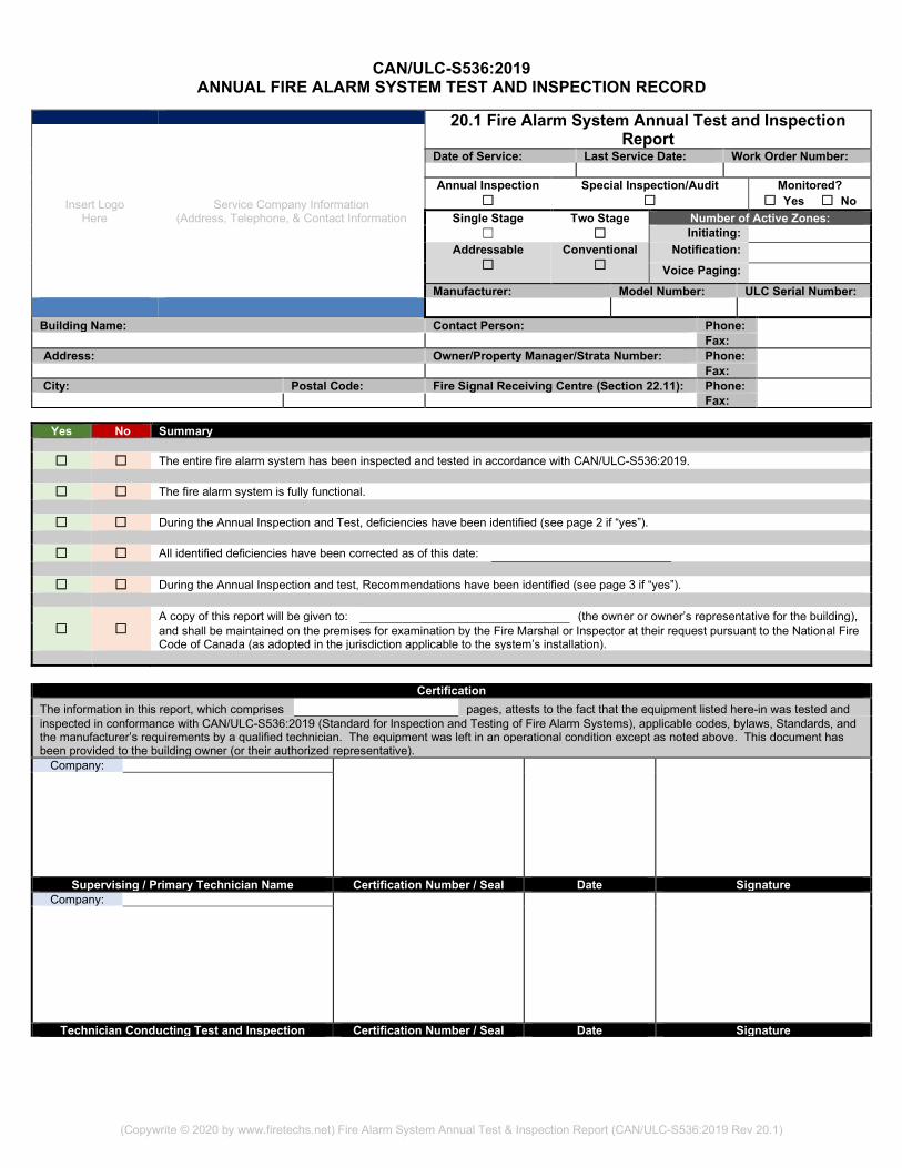
CAN/ULC-S536:2019 ANNUAL FIRE ALARM SYSTEM TEST AND INSPECTION RECORD
20.1 Fire Alarm System Annual Test and Inspection
Report
Insert Logo Here
Service Company Information (Address, Telephone, & Contact Information
Date of Service: Last Service Date: Work Order Number:
Annual Inspection ☐
Special Inspection/Audit ☐
Monitored? ☐ Yes ☐ No
Single Stage ☐
Two Stage ☐
Number of Active Zones: Initiating:
Addressable ☐
Conventional ☐
Notification: Voice Paging:
Manufacturer: Model Number: ULC Serial Number: Building Name: Contact Person: Phone: Fax: Address: Owner/Property Manager/Strata Number: Phone: Fax: City: Postal Code: Fire Signal Receiving Centre (Section 22.11): Phone: Fax:
Yes No Summary
☐ ☐ The entire fire alarm system has been inspected and tested in accordance with CAN/ULC-S536:2019.
☐ ☐ The fire alarm system is fully functional.
☐ ☐ During the Annual Inspection and Test, deficiencies have been identified (see page 2 if “yes”).
☐ ☐ All identified deficiencies have been corrected as of this date:
☐ ☐ During the Annual Inspection and test, Recommendations have been identified (see page 3 if “yes”).
☐ ☐ A copy of this report will be given to: (the owner or owner’s representative for the building), and shall be maintained on the premises for examination by the Fire Marshal or Inspector at their request pursuant to the National Fire Code of Canada (as adopted in the jurisdiction applicable to the system’s installation).
Certification The information in this report, which comprises pages, attests to the fact that the equipment listed here-in was tested and inspected in conformance with CAN/ULC-S536:2019 (Standard for Inspection and Testing of Fire Alarm Systems), applicable codes, bylaws, Standards, and the manufacturer’s requirements by a qualified technician. The equipment was left in an operational condition except as noted above. This document has been provided to the building owner (or their authorized representative).
Company:
Supervising / Primary Technician Name Certification Number / Seal Date Signature Company:
Technician Conducting Test and Inspection Certification Number / Seal Date Signature

CAN/ULC-S536:2019 – FIRE ALARM SYSTEM INSPECTION AND TEST RECORD Building Name: Date:
Address: City:
(Copywrite © 2020 by www.firetechs.net) Fire Alarm System Annual Test & Inspection Report (CAN/ULC-S536:2019 Rev 20.1) Page _____ of ______
20.2 DEFICIENCIES The inspection and Testing of any corrections/repairs of deficiencies noted on this form has been completed
by qualified personnel identified in the column marked “Technician Name & Certificate No.” To be completed by the primary individual who conducted the test and inspection. To be completed by the primary individual responsible for the repair.
Item #
Device Type
Device Location Deficiency CAN/ULC-S536
Clause Reference Date
Corrected (MM/DD/YY)
Work Order or Reference #
Name of Service Provider Responsible
for the Repair Technician Name & Certificate No.
Item # Control Function or Feature Deficiency CAN/ULC-S536
Clause Reference Date
Corrected (MM/DD/YY)
Work Order or Reference #
Name of Service Provider Responsible
for the Repair Technician Name & Certificate No.
BUILDING OWNER’S / REPRESENTATIVE’S COMPLIANCE STATEMENT I understand that all deficiencies noted in the table above have been corrected.
Printed Name: Signature: Date:
MM DD YY
CAN/ULC-S536:2019 – FIRE ALARM SYSTEM INSPECTION AND TEST RECORD Building Name: Date:
Address: City:
(Copywrite © 2020 by www.firetechs.net) Fire Alarm System Annual Test & Inspection Report (CAN/ULC-S536:2019 Rev 20.1) Page _____ of ______
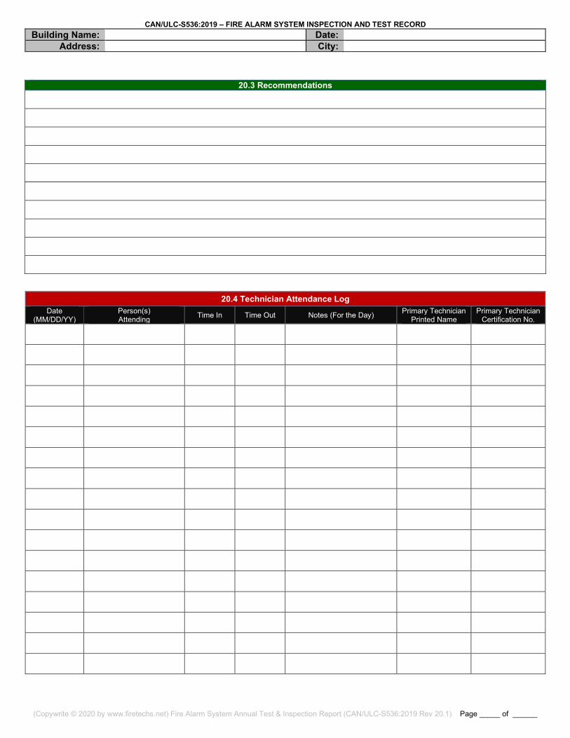
20.3 Recommendations
20.4 Technician Attendance Log Date
(MM/DD/YY) Person(s) Attending Time In Time Out Notes (For the Day) Primary Technician
Printed Name Primary Technician
Certification No.
CAN/ULC-S536:2019 – FIRE ALARM SYSTEM INSPECTION AND TEST RECORD Building Name: Date:
Address: City:
(Copywrite © 2020 by www.firetechs.net) Fire Alarm System Annual Test & Inspection Report (CAN/ULC-S536:2019 Rev 20.1) Page _____ of ______
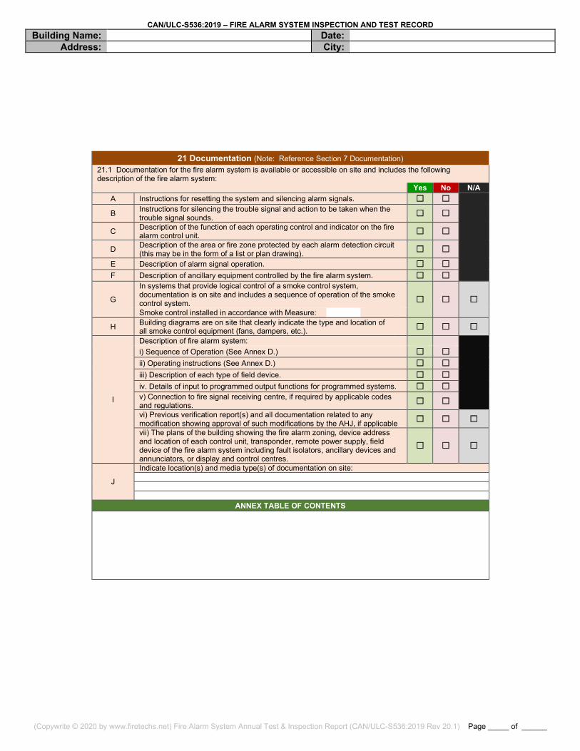
21 Documentation (Note: Reference Section 7 Documentation) 21.1 Documentation for the fire alarm system is available or accessible on site and includes the following description of the fire alarm system: Yes No N/A
A Instructions for resetting the system and silencing alarm signals. ☐ ☐
B Instructions for silencing the trouble signal and action to be taken when the trouble signal sounds. ☐ ☐
C Description of the function of each operating control and indicator on the fire alarm control unit. ☐ ☐
D Description of the area or fire zone protected by each alarm detection circuit (this may be in the form of a list or plan drawing). ☐ ☐
E Description of alarm signal operation. ☐ ☐ F Description of ancillary equipment controlled by the fire alarm system. ☐ ☐
G
In systems that provide logical control of a smoke control system, documentation is on site and includes a sequence of operation of the smoke control system. ☐ ☐ ☐ Smoke control installed in accordance with Measure:
H Building diagrams are on site that clearly indicate the type and location of all smoke control equipment (fans, dampers, etc.). ☐ ☐ ☐
I
Description of fire alarm system:
i) Sequence of Operation (See Annex D.) ☐ ☐ ii) Operating instructions (See Annex D.) ☐ ☐ iii) Description of each type of field device. ☐ ☐ iv. Details of input to programmed output functions for programmed systems. ☐ ☐ v) Connection to fire signal receiving centre, if required by applicable codes and regulations. ☐ ☐ vi) Previous verification report(s) and all documentation related to any modification showing approval of such modifications by the AHJ, if applicable ☐ ☐ ☐ vii) The plans of the building showing the fire alarm zoning, device address and location of each control unit, transponder, remote power supply, field device of the fire alarm system including fault isolators, ancillary devices and annunciators, or display and control centres.
☐ ☐ ☐
J
Indicate location(s) and media type(s) of documentation on site:
ANNEX TABLE OF CONTENTS

CAN/ULC-S536:2019 – FIRE ALARM SYSTEM INSPECTION AND TEST RECORD Building Name: Date:
Address: City:
(Copywrite © 2020 by www.firetechs.net) Fire Alarm System Annual Test & Inspection Report (CAN/ULC-S536:2019 Rev 20.1) Page _____ of ______
“Yes” - Tested correctly “No” - Did not test correctly (For NO answers refer to Section 20.2 Deficiencies) “NA” = Not applicable (the feature is not available or has not been programmed)
20.1 Control Unit or Transponder Inspection (Reference Clause 8.2) Complete section for each control unit or transponder.
Control Unit/Transponder Field Location: Control Unit/Transponder Identification:
Yes No N/A A Input circuit designations correctly identified in relation to connected field devices. ☐ ☐ ☐ B Output circuit designations correctly identified in relation to connected field devices. ☐ ☐ ☐ C Correct designations for common control functions and indicators. ☐ ☐ ☐ D Plug-in components and modules securely in place. ☐ ☐ ☐ E Plug-in cables securely in place. ☐ ☐ ☐
F
Record the date, revision and version of firmware: Date: Revision: Version:
Record the date, revision and version of the program software: Date: Revision: Version:
G Control unit/transponder is clean and free of dust and dirt. ☐ ☐ ☐ H Fuses in accordance with the manufacturer’s specification. ☐ ☐ ☐ I Control unit/transponder lock is functional. ☐ ☐ ☐ J Termination points for wiring to field devices secure. ☐ ☐ ☐
22.1 Control Unit or Transponder Record (Reference Clause 8.3) Control Unit/Transponder Field Location:
Control Unit/Transponder Identification: Yes No N/A
A Power ‘on’ visual indicator operates. ☐ ☐ ☐ B Time and date indication corresponds with local time and date. ☐ ☐ ☐ C Common visual trouble signal operates. ☐ ☐ ☐ D Common audible trouble signal operates. ☐ ☐ ☐ E Trouble signal silence switch operates. ☐ ☐ ☐ F Main Power supply failure trouble signal operates. ☐ ☐ ☐ G Ground fault tested on positive and negative initiates trouble signal. ☐ ☐ ☐ H Alert signal operates. ☐ ☐ ☐ I Alarm signal operates. ☐ ☐ ☐ J Automatic transfer from alert signal to alarm signal operates. Time: ☐ ☐ ☐ K Manual transfer from alert signal to alarm signal. ☐ ☐ ☐ L Automatic transfer from alert to alarm signal cancel (acknowledge) operates on a two stage system. ☐ ☐ ☐ M Alarm signal silence inhibit function operates. ☐ ☐ ☐ N Alarm signal manual silence operates. ☐ ☐ ☐ O Alarm signal silence visual indication operates ☐ ☐ ☐ P Alarm signal when silenced, automatically reinitiate only upon subsequent alarm from another NBC required fire
alarm zone. ☐ ☐ ☐
Q Duration of alarm signal prior to automatic silence. Time: ☐ R Audible, visual, alert, and alarm signals programmed and operate per design and specification; or
documentation as provided in Section 21. ☐ ☐ ☐
S Input circuit alarm and supervisory operation including audible and visual indicator operates. ☐ ☐ ☐ T Input circuit supervision fault causes a trouble indication. ☐ ☐ ☐ U Output circuit alarm indicators operate. ☐ ☐ ☐ V Output circuit supervision fault causes a trouble indication. ☐ ☐ ☐ W Visual indicator test (lamp test) operates. ☐ ☐ ☐
X Coded signal sequence operates not less than the required number of times and the correct alarm signal thereafter. ☐ ☐ ☐
Y Coded signal sequences are not interrupted by subsequent alarms. ☐ ☐ ☐ Z Ancillary device by-pass results in trouble signal. ☐ ☐ ☐
AA Input circuit to output circuit operation including ancillary device for correct program operation as per design and specification, or documentation as detailed in Annex D, Description of Fire Alarm System for Inspection and Test Procedures.
☐ ☐ ☐
BB System Reset operates. ☐ ☐ ☐ CC Main power to emergency power supply transfer operates. ☐ ☐ ☐ DD Smoke detector alarm verification (status change confirmation) verified. [Refer to 14.4.3, Smoke Detector Alarm
Verification (Status Change Confirmation)]. ☐ ☐ ☐
CAN/ULC-S536:2019 – FIRE ALARM SYSTEM INSPECTION AND TEST RECORD Building Name: Date:
Address: City:
(Copywrite © 2020 by www.firetechs.net) Fire Alarm System Annual Test & Inspection Report (CAN/ULC-S536:2019 Rev 20.1) Page _____ of ______
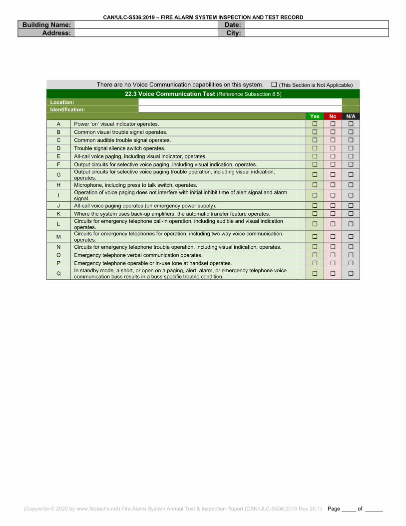
There are no Voice Communication capabilities on this system. ☐ (This Section is Not Applicable) 22.3 Voice Communication Test (Reference Subsection 8.5)
Location: Identification: Yes No N/A
A Power ‘on’ visual indicator operates. ☐ ☐ ☐ B Common visual trouble signal operates. ☐ ☐ ☐ C Common audible trouble signal operates. ☐ ☐ ☐ D Trouble signal silence switch operates. ☐ ☐ ☐ E All-call voice paging, including visual indicator, operates. ☐ ☐ ☐ F Output circuits for selective voice paging, including visual indication, operates. ☐ ☐ ☐ G Output circuits for selective voice paging trouble operation, including visual indication,
operates. ☐ ☐ ☐ H Microphone, including press to talk switch, operates. ☐ ☐ ☐
I Operation of voice paging does not interfere with initial inhibit time of alert signal and alarm signal. ☐ ☐ ☐
J All-call voice paging operates (on emergency power supply). ☐ ☐ ☐ K Where the system uses back-up amplifiers, the automatic transfer feature operates. ☐ ☐ ☐ L Circuits for emergency telephone call-in operation, including audible and visual indication
operates. ☐ ☐ ☐
M Circuits for emergency telephones for operation, including two-way voice communication, operates. ☐ ☐ ☐
N Circuits for emergency telephone trouble operation, including visual indication, operates. ☐ ☐ ☐ O Emergency telephone verbal communication operates. ☐ ☐ ☐ P Emergency telephone operable or in-use tone at handset operates. ☐ ☐ ☐
Q In standby mode, a short, or open on a paging, alert, alarm, or emergency telephone voice communication buss results in a buss specific trouble condition. ☐ ☐ ☐

CAN/ULC-S536:2019 – FIRE ALARM SYSTEM INSPECTION AND TEST RECORD Building Name: Date:
Address: City:
(Copywrite © 2020 by www.firetechs.net) Fire Alarm System Annual Test & Inspection Report (CAN/ULC-S536:2019 Rev 20.1) Page _____ of ______
22.4 Power Supply Inspection (Reference Section 9 Power Supplies)
Power Supply Field Location: Power Supply Identification:
Circuit Disconnect Means Location: Circuit Panel/Breaker Identification:
Yes No N/A A Fused in accordance with the manufacturer’s marked rating of the system. ☐ ☐ ☐ B The primary supply is equipped with identified disconnect means. ☐ ☐ ☐ C Adequate to meet the requirements of the system. ☐ ☐ ☐ D A short on the isolated side of each power isolation module results in a trouble condition. ☐ ☐ ☐ E Operation of a device on the source side of each shorted power isolation module is confirmed. ☐ ☐ ☐
F Power for ancillary devices is taken from a source separate from the fire alarm system control unit or transponder power supply. ☐ ☐ ☐
G Power for ancillary devices is taken from the control unit or transponder that is designed to provide such power. ☐ ☐ ☐
H Ancillary devices, which are powered from the control unit or transponder, are recorded. ☐ ☐ ☐ 22.5 Emergency Power Supply Test And Inspection
Emergency Power Supply Field Location: Emergency Power Supply Identification:
Emergency power supply is provided by: ☐ Batteries ☐ Generator ☐ UPS ☐ Combination Battery Type (as installed): ☐ Sealed Lead Acid ☐ Ni-Cad ☐ Lithium-Ion ☐ Wet Lead Battery Capacity (as installed): AH NBC required full load alarm operation time: ☐ 2 hours ☐ 1 hour ☐ 30 minutes ☐ 5 minutes Yes No N/A
A Correct battery type as recommended by the manufacturer. ☐ ☐ ☐ B Correct battery rating as determined by battery calculations based on full system load. ☐ ☐ ☐
C Battery voltage (main power “on”): VDC
Battery charging current (main power “on”): mA
D Battery voltage – main power “off” – FAS in supervisory condition: VDC Battery current - main power “off” – FAS in supervisory condition: mA
E Battery voltage – main power “off” – FAS in full load ALARM: VDC Battery current – main power “off” – FAS in full load ALARM: A
F Battery free of physical damage. ☐ ☐ ☐ G Battery terminals cleaned and lubricated. ☐ ☐ ☐ H Battery terminals clamped tightly. ☐ ☐ ☐ I Correct electrolyte level. ☐ ☐ ☐ J Specific gravity of the electrolyte is within the battery manufacturer’s specifications. ☐ ☐ ☐ K Inspected for electrolyte leakage. ☐ ☐ ☐ L Adequately ventilated. ☐ ☐ ☐ M Record manufacturer’s date code or in-service date: N Disconnection causes trouble signal. ☐ ☐ ☐
O
Indicate type of test performed on a fully charged battery (select one): (i) Required supervisory load for 24 h followed by the required full load operation; ☐ ☐ ☐
(ii) Silent accelerated test. (Refer to Annex C1, New Silent Accelerated Test Method); or ☐ ☐ ☐
(iii) Battery manufacturer’s method. ☐ ☐ ☐ Specify: P Record calculated battery capacity (refer to Annex C2). AH Q Record the battery terminal voltage after tests are completed. VDC R Battery voltage not less than 85% of its rated capacity after tests completed. ☐ ☐ ☐
Emergency Power Generator Tests (Reference Section 9.3) A Generator provides power to the AC circuit serving the fire alarm system. ☐ ☐ ☐
B Trouble condition at the emergency generator shall result in an audible common trouble signal and a visual indication at the required annunciator. ☐ ☐ ☐
C Generator “Run” condition at the emergency generator shall result in an audible common trouble signal and a visual indication at the required annunciator. ☐ ☐ ☐
Recommended Additional Inspection (not mandated by the Standard): Generator fueled by: ☐ Diesel ☐ Natural Gas ☐ Other: Fuel Level: % of full capacity Estimated run time: Hours
CAN/ULC-S536:2019 – FIRE ALARM SYSTEM INSPECTION AND TEST RECORD Building Name: Date:
Address: City:
(Copywrite © 2020 by www.firetechs.net) Fire Alarm System Annual Test & Inspection Report (CAN/ULC-S536:2019 Rev 20.1) Page _____ of ______
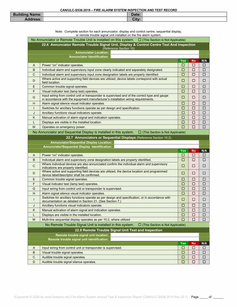
Note: Complete section for each annunciator, display and control centre, sequential display,
or remote trouble signal unit installed on the fire alarm system. No Annunciator or Remote Trouble Unit is installed on this system. ☐ (This Section is Not Applicable)
22.6 Annunciator Remote Trouble Signal Unit, Display & Control Centre Test And Inspection (Reference Section 10)
Annunciator Location: Annunciator Identification:
Yes No N/A A Power “on” indicator operates. ☐ ☐ ☐ B Individual alarm and supervisory input zone clearly indicated and separately designated. ☐ ☐ ☐ C Individual alarm and supervisory input zone designation labels are properly identified. ☐ ☐ ☐
D Where active and supporting field devices are utilized, device labels correspond with actual field location. ☐ ☐ ☐
E Common trouble signal operates. ☐ ☐ ☐ F Visual indicator test (lamp test) operates. ☐ ☐ ☐ G Input wiring from control unit or transponder is supervised and of the correct type and gauge
in accordance with the equipment manufacturer’s installation wiring requirements. ☐ ☐ ☐
H Alarm signal silence visual indicator operates. ☐ ☐ ☐ I Switches for ancillary functions operate as per design and specification. ☐ ☐ ☐ J Ancillary functions visual indicators operate. ☐ ☐ ☐ K Manual activation of alarm signal and indication operates. ☐ ☐ ☐ L Displays are visible in the installed location. ☐ ☐ ☐ M Operates on emergency power. ☐ ☐ ☐ No Annunciator and Sequential Display is installed in this system. ☐ (This Section is Not Applicable)
22.7 Annunciators or Sequential Displays (Reference Section 10.2) Annunciator/Sequential Display Location:
Annunciator/Sequential Display Identification: Yes No N/A
A Power “on” indicator operates. ☐ ☐ ☐ B Individual alarm and supervisory zone designation labels are properly identified. ☐ ☐ ☐
C Where individual devices are also annunciated confirm the individual alarm and supervisory indications are properly identified. ☐ ☐ ☐
D Where active and supporting field devices are utilized, the device location and programmed device label/descriptor shall be confirmed. ☐ ☐ ☐
E Common trouble signal operates. ☐ ☐ ☐ F Visual indicator test (lamp test) operates. ☐ ☐ ☐ G Input wiring from control unit or transponder is supervised. ☐ ☐ ☐ H Alarm signal silence visual indicator operates. ☐ ☐ ☐
I Switches for ancillary functions operate as per design and specification, or in accordance with documentation as detailed in Section 21. (See Section 7.) ☐ ☐ ☐
J Ancillary functions visual indicators operate. ☐ ☐ ☐ K Manual activation of alarm signal and indication operates. ☐ ☐ ☐ L Displays are visible in the installed location. ☐ ☐ ☐ M Multi-line sequential display operates as per 10.2, where utilized ☐ ☐ ☐
No Remote Trouble Signal Unit is installed in this system. ☐ (This Section is Not Applicable) 22.8 Remote Trouble Signal Unit Test and Inspection
Remote trouble signal unit location: Remote trouble signal unit identification:
Yes No N/A A Input wiring from control unit or transponder is supervised. ☐ ☐ ☐ B Visual trouble signal operates. ☐ ☐ ☐ C Audible trouble signal operates. ☐ ☐ ☐ D Audible trouble signal silence operates. ☐ ☐ ☐
CAN/ULC-S536:2019 – FIRE ALARM SYSTEM INSPECTION AND TEST RECORD Building Name: Date:
Address: City:
(Copywrite © 2020 by www.firetechs.net) Fire Alarm System Annual Test & Inspection Report (CAN/ULC-S536:2019 Rev 20.1) Page _____ of ______
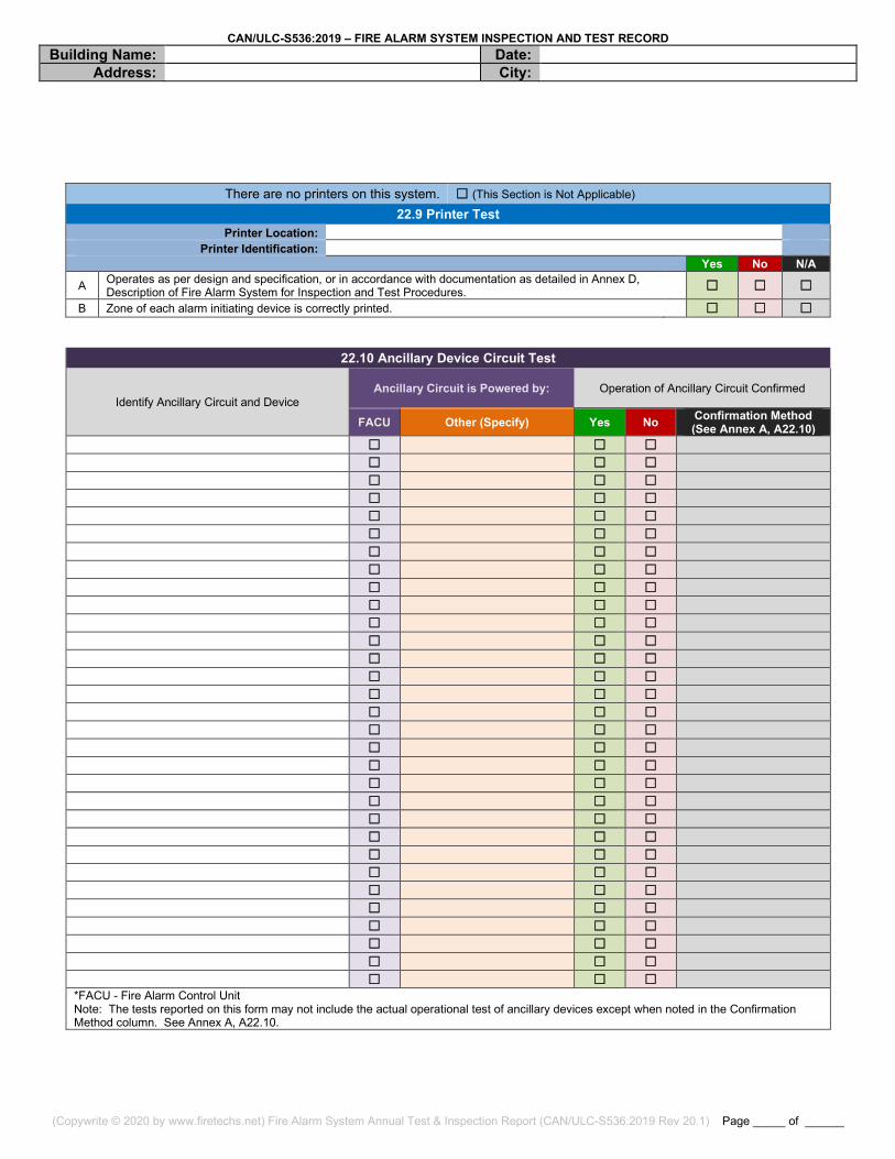
There are no printers on this system. ☐ (This Section is Not Applicable) 22.9 Printer Test
Printer Location: Printer Identification:
Yes No N/A
A Operates as per design and specification, or in accordance with documentation as detailed in Annex D, Description of Fire Alarm System for Inspection and Test Procedures.
☐ ☐ ☐ B Zone of each alarm initiating device is correctly printed. ☐ ☐ ☐
22.10 Ancillary Device Circuit Test
Identify Ancillary Circuit and Device Ancillary Circuit is Powered by: Operation of Ancillary Circuit Confirmed
FACU Other (Specify) Yes No Confirmation Method (See Annex A, A22.10)
☐ ☐ ☐ ☐ ☐ ☐ ☐ ☐ ☐ ☐ ☐ ☐ ☐ ☐ ☐ ☐ ☐ ☐ ☐ ☐ ☐ ☐ ☐ ☐ ☐ ☐ ☐ ☐ ☐ ☐ ☐ ☐ ☐ ☐ ☐ ☐ ☐ ☐ ☐ ☐ ☐ ☐ ☐ ☐ ☐ ☐ ☐ ☐ ☐ ☐ ☐ ☐ ☐ ☐ ☐ ☐ ☐ ☐ ☐ ☐ ☐ ☐ ☐ ☐ ☐ ☐ ☐ ☐ ☐ ☐ ☐ ☐ ☐ ☐ ☐ ☐ ☐ ☐ ☐ ☐ ☐ ☐ ☐ ☐ ☐ ☐ ☐ ☐ ☐ ☐ ☐ ☐ ☐ *FACU - Fire Alarm Control Unit Note: The tests reported on this form may not include the actual operational test of ancillary devices except when noted in the Confirmation Method column. See Annex A, A22.10.
CAN/ULC-S536:2019 – FIRE ALARM SYSTEM INSPECTION AND TEST RECORD Building Name: Date:
Address: City:
(Copywrite © 2020 by www.firetechs.net) Fire Alarm System Annual Test & Inspection Report (CAN/ULC-S536:2019 Rev 20.1) Page _____ of ______
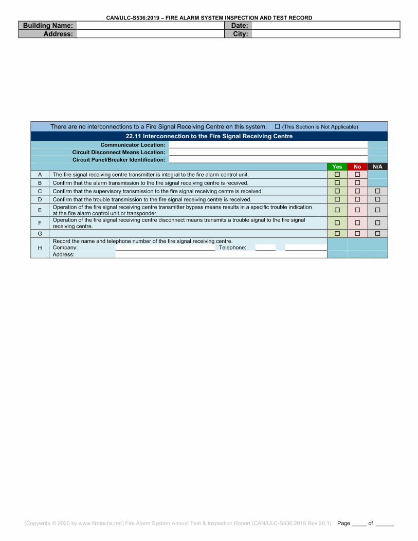
There are no interconnections to a Fire Signal Receiving Centre on this system. ☐ (This Section is Not Applicable) 22.11 Interconnection to the Fire Signal Receiving Centre
Communicator Location: Circuit Disconnect Means Location: Circuit Panel/Breaker Identification:
Yes No N/A A The fire signal receiving centre transmitter is integral to the fire alarm control unit. ☐ ☐ B Confirm that the alarm transmission to the fire signal receiving centre is received. ☐ ☐ C Confirm that the supervisory transmission to the fire signal receiving centre is received. ☐ ☐ ☐ D Confirm that the trouble transmission to the fire signal receiving centre is received. ☐ ☐ ☐
E Operation of the fire signal receiving centre transmitter bypass means results in a specific trouble indication at the fire alarm control unit or transponder ☐ ☐ ☐
F Operation of the fire signal receiving centre disconnect means transmits a trouble signal to the fire signal receiving centre. ☐ ☐ ☐
G ☐ ☐ ☐
H Record the name and telephone number of the fire signal receiving centre. Company: Telephone: Address:
CAN/ULC-S536:2019 – FIRE ALARM SYSTEM INSPECTION AND TEST RECORD Building Name: Date:
Address: City:
(Copywrite © 2020 by www.firetechs.net) Fire Alarm System Annual Test & Inspection Report (CAN/ULC-S536:2019 Rev 20.1) Page _____ of ______
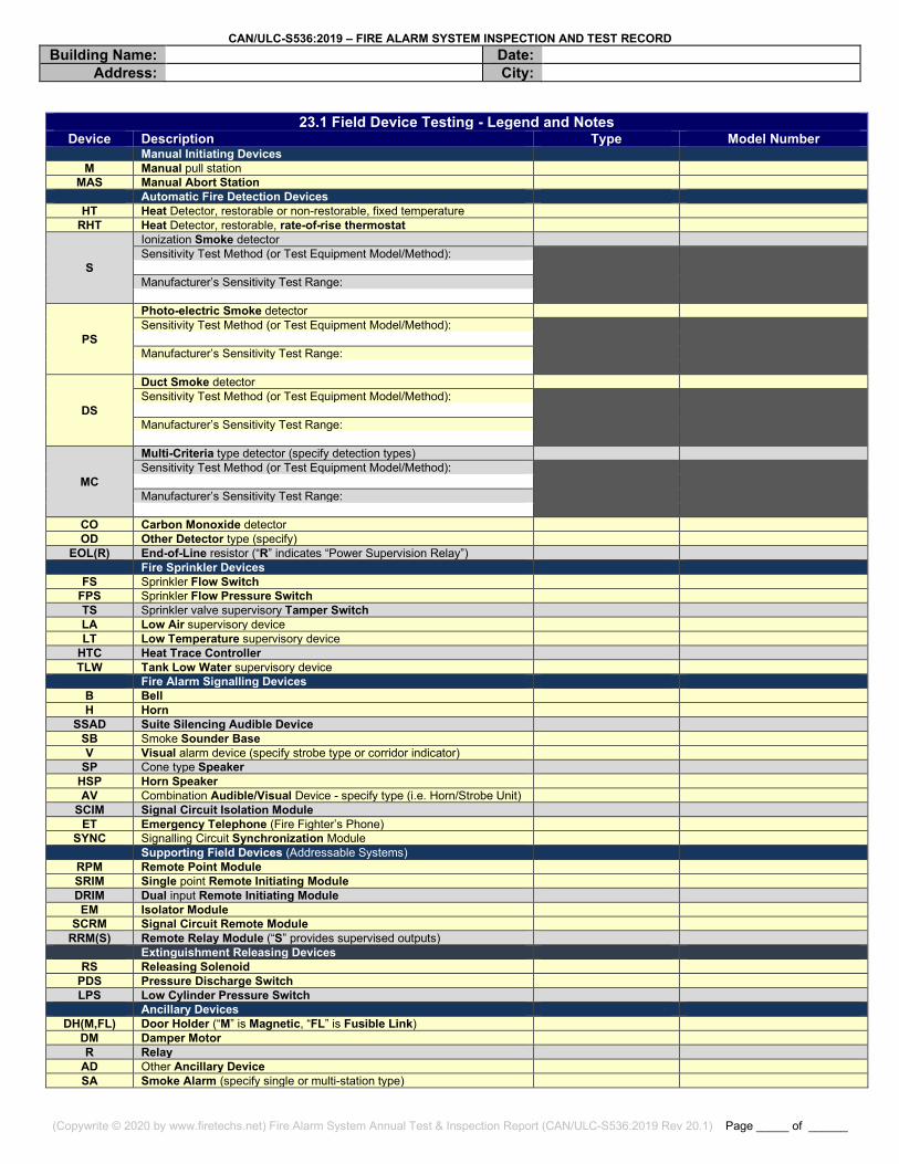
23.1 Field Device Testing - Legend and Notes
Device Description Type Model Number Manual Initiating Devices
M Manual pull station MAS Manual Abort Station
Automatic Fire Detection Devices HT Heat Detector, restorable or non-restorable, fixed temperature
RHT Heat Detector, restorable, rate-of-rise thermostat
S
Ionization Smoke detector Sensitivity Test Method (or Test Equipment Model/Method):
Manufacturer’s Sensitivity Test Range:
PS
Photo-electric Smoke detector Sensitivity Test Method (or Test Equipment Model/Method):
Manufacturer’s Sensitivity Test Range:
DS
Duct Smoke detector Sensitivity Test Method (or Test Equipment Model/Method):
Manufacturer’s Sensitivity Test Range:
MC
Multi-Criteria type detector (specify detection types) Sensitivity Test Method (or Test Equipment Model/Method):
Manufacturer’s Sensitivity Test Range:
CO Carbon Monoxide detector OD Other Detector type (specify)
EOL(R) End-of-Line resistor (“R” indicates “Power Supervision Relay”) Fire Sprinkler Devices
FS Sprinkler Flow Switch FPS Sprinkler Flow Pressure Switch TS Sprinkler valve supervisory Tamper Switch LA Low Air supervisory device LT Low Temperature supervisory device
HTC Heat Trace Controller TLW Tank Low Water supervisory device
Fire Alarm Signalling Devices B Bell H Horn
SSAD Suite Silencing Audible Device SB Smoke Sounder Base V Visual alarm device (specify strobe type or corridor indicator)
SP Cone type Speaker HSP Horn Speaker AV Combination Audible/Visual Device - specify type (i.e. Horn/Strobe Unit)
SCIM Signal Circuit Isolation Module ET Emergency Telephone (Fire Fighter’s Phone)
SYNC Signalling Circuit Synchronization Module Supporting Field Devices (Addressable Systems)
RPM Remote Point Module SRIM Single point Remote Initiating Module DRIM Dual input Remote Initiating Module EM Isolator Module
SCRM Signal Circuit Remote Module RRM(S) Remote Relay Module (“S” provides supervised outputs)
Extinguishment Releasing Devices RS Releasing Solenoid
PDS Pressure Discharge Switch LPS Low Cylinder Pressure Switch
Ancillary Devices DH(M,FL) Door Holder (“M” is Magnetic, “FL” is Fusible Link)
DM Damper Motor R Relay
AD Other Ancillary Device SA Smoke Alarm (specify single or multi-station type)
CAN/ULC-S536:2019 – FIRE ALARM SYSTEM INSPECTION AND TEST RECORD Building Name: Date:
Address: City:
(Copywrite © 2020 by www.firetechs.net) Fire Alarm System Annual Test & Inspection Report (CAN/ULC-S536:2019 Rev 20.1) Page _____ of ______
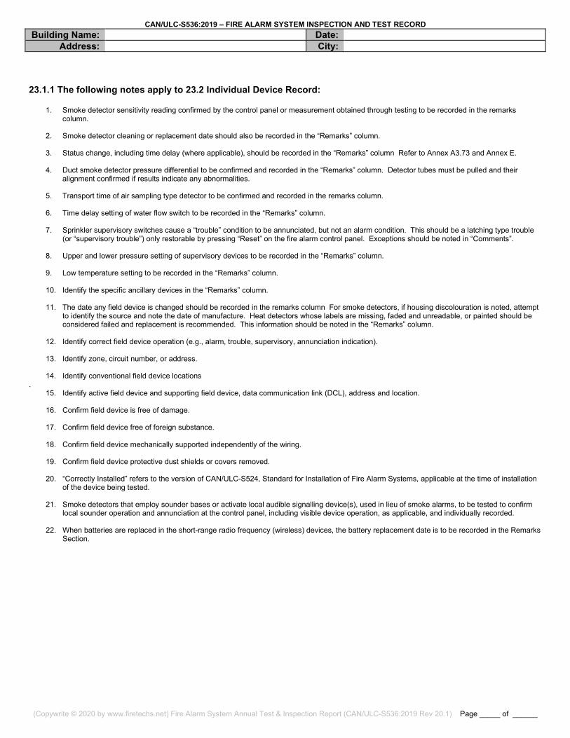
23.1.1 The following notes apply to 23.2 Individual Device Record:
1. Smoke detector sensitivity reading confirmed by the control panel or measurement obtained through testing to be recorded in the remarks column.
2. Smoke detector cleaning or replacement date should also be recorded in the “Remarks” column.
3. Status change, including time delay (where applicable), should be recorded in the “Remarks” column Refer to Annex A3.73 and Annex E.
4. Duct smoke detector pressure differential to be confirmed and recorded in the “Remarks” column. Detector tubes must be pulled and their alignment confirmed if results indicate any abnormalities.
5. Transport time of air sampling type detector to be confirmed and recorded in the remarks column.
6. Time delay setting of water flow switch to be recorded in the “Remarks” column.
7. Sprinkler supervisory switches cause a “trouble” condition to be annunciated, but not an alarm condition. This should be a latching type trouble (or “supervisory trouble”) only restorable by pressing “Reset” on the fire alarm control panel. Exceptions should be noted in “Comments”.
8. Upper and lower pressure setting of supervisory devices to be recorded in the “Remarks” column.
9. Low temperature setting to be recorded in the “Remarks” column.
10. Identify the specific ancillary devices in the “Remarks” column.
11. The date any field device is changed should be recorded in the remarks column For smoke detectors, if housing discolouration is noted, attempt
to identify the source and note the date of manufacture. Heat detectors whose labels are missing, faded and unreadable, or painted should be considered failed and replacement is recommended. This information should be noted in the “Remarks” column.
12. Identify correct field device operation (e.g., alarm, trouble, supervisory, annunciation indication).
13. Identify zone, circuit number, or address.
14. Identify conventional field device locations
. 15. Identify active field device and supporting field device, data communication link (DCL), address and location.
16. Confirm field device is free of damage.
17. Confirm field device free of foreign substance.
18. Confirm field device mechanically supported independently of the wiring.
19. Confirm field device protective dust shields or covers removed.
20. “Correctly Installed” refers to the version of CAN/ULC-S524, Standard for Installation of Fire Alarm Systems, applicable at the time of installation
of the device being tested.
21. Smoke detectors that employ sounder bases or activate local audible signalling device(s), used in lieu of smoke alarms, to be tested to confirm local sounder operation and annunciation at the control panel, including visible device operation, as applicable, and individually recorded.
22. When batteries are replaced in the short-range radio frequency (wireless) devices, the battery replacement date is to be recorded in the Remarks
Section.

CAN/ULC-S536:2019 – FIRE ALARM SYSTEM INSPECTION AND TEST RECORD Building Name: Date:
Address: City:
(Copywrite © 2020 by www.firetechs.net) Fire Alarm System Annual Test & Inspection Report (CAN/ULC-S536:2019 Rev 20.1) Page _____ of ______
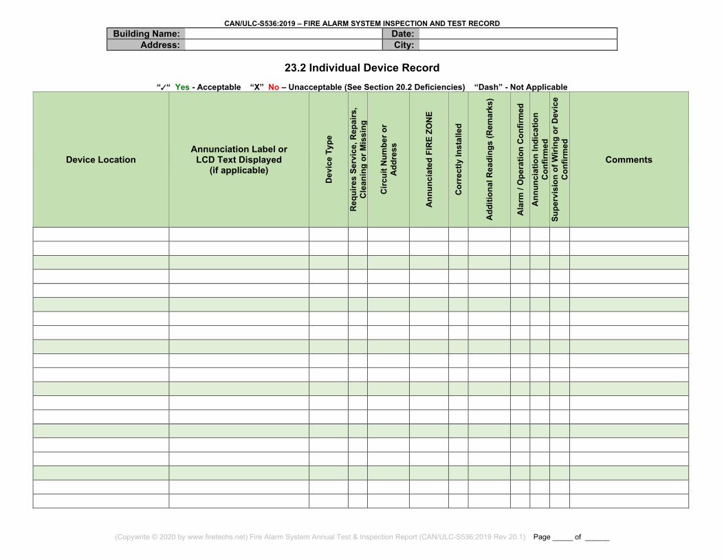
23.2 Individual Device Record
““ Yes - Acceptable “X” No – Unacceptable (See Section 20.2 Deficiencies) “Dash” - Not Applicable
Device Location Annunciation Label or
LCD Text Displayed (if applicable)
Dev
ice
Type
Req
uire
s Se
rvic
e, R
epai
rs,
Cle
anin
g or
Mis
sing
Circ
uit N
umbe
r or
Add
ress
Ann
unci
ated
FIR
E ZO
NE
Cor
rect
ly In
stal
led
Add
ition
al R
eadi
ngs
(Rem
arks
)
Ala
rm /
Ope
ratio
n C
onfir
med
A
nnun
ciat
ion
Indi
catio
n C
onfir
med
Supe
rvis
ion
of W
iring
or D
evic
e C
onfir
med
Comments
CAN/ULC-S536:2019 – FIRE ALARM SYSTEM INSPECTION AND TEST RECORD Building Name: Date:
Address: City:
(Copywrite © 2020 by www.firetechs.net) Fire Alarm System Annual Test & Inspection Report (CAN/ULC-S536:2019 Rev 20.1) Page _____ of ______
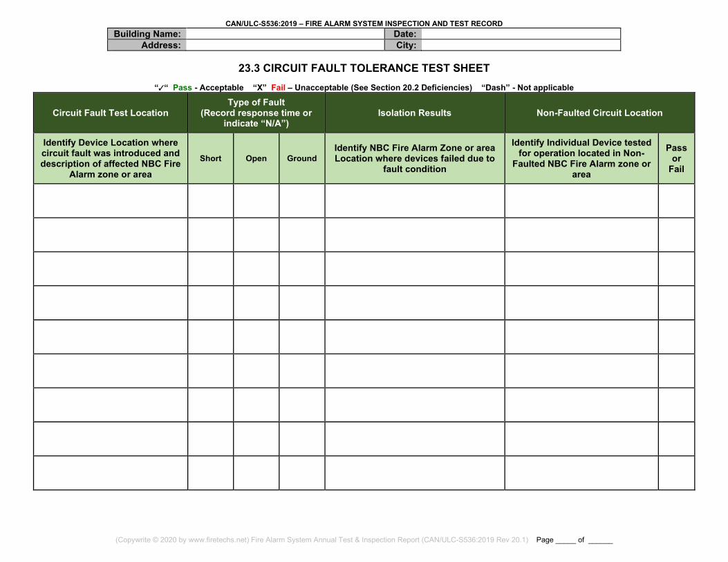
23.3 CIRCUIT FAULT TOLERANCE TEST SHEET
““ Pass - Acceptable “X” Fail – Unacceptable (See Section 20.2 Deficiencies) “Dash” - Not applicable
Circuit Fault Test Location Type of Fault
(Record response time or indicate “N/A”)
Isolation Results Non-Faulted Circuit Location
Identify Device Location where circuit fault was introduced and description of affected NBC Fire
Alarm zone or area Short Open Ground
Identify NBC Fire Alarm Zone or area Location where devices failed due to
fault condition
Identify Individual Device tested for operation located in Non-
Faulted NBC Fire Alarm zone or area
Pass or
Fail