canalis busbar trunking (eng) - trinet grup · canalis kle, kba or kbb canalis kba or kbb the type...
TRANSCRIPT
11068/2 Te
Busbar trunking for lightingBusbar trunking degrees of protection
Selection
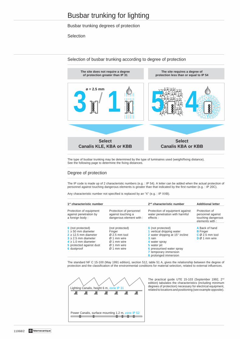
Selection of busbar trunking according to degree of protection
The site does not require a degree The site requires a degree ofof protection greater than IP 31 protection less than or equal to IP 54
Select SelectCanalis KLE, KBA or KBB Canalis KBA or KBB
The type of busbar trunking may be determined by the type of luminaires used (weight/fixing distance).See the following page to determine the fixing distances.
Degree of protection
The IP code is made up of 2 characteristic numbers (e.g. : IP 54). A letter can be added when the actual protection ofpersonnel against touching dangerous elements is greater than that indicated by the first number (e.g. : IP 20C).
Any characteristic number not specified is replaced by an “X” (e.g. : IP XXB).
1st characteristic number 2 nd characteristic number Additional letter
Protection of equipment Protection of personnel Protection of equipment against Protection ofagainst penetration by against touching a water penetration with harmful personnel againsta foreign body : dangerous element with : effects : touching dangerous
elements with :
0 (not protected) (not protected) 0 (not protected) A Back of hand1 ≥ 50 mm diameter Finger 1 vertical dripping water B Finger2 ≥ 12.5 mm diameter Ø 2.5 mm tool 2 water dripping at 15° incline C Ø 2.5 mm tool3 ≥ 2.5 mm diameter Ø 1 mm wire 3 rain D Ø 1 mm wire4 ≥ 1.0 mm diameter Ø 1 mm wire 4 water spray5 protected against dust Ø 1 mm wire 5 water jet6 dustproof Ø 1 mm wire 6 pressurised water spray
7 temporary immersion8 prolonged immersion
The standard NF C 15-100 (May 1991 edition), section 512, table 51 A, gives the relationship between the degree ofprotection and the classification of the environmental conditions for material selection, related to external influences.
The practical guide UTE 15-103 (September 1992, 2nd
edition) tabulates the characteristics (including minimumdegrees of protection) necessary for electrical equipment,related to locations and positioning (see example opposite).
13 45ø = 2.5 mm
Lighting Canalis, height 6 m, zone IP 31
Power Canalis, surface mounting 1.2 m, zone IP 52
11068/3Te
Busbar trunking for lightingDetermining the busbar trunking depending on the type and number of luminaires
Selection
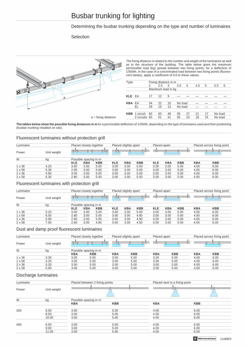
The fixing distance is related to the number and weight of the luminaires as wellas to the structure of the building. The table below gives the maximumpermissible load (kg) spread between two fixing points, for a deflection of1/500th. In the case of a concentrated load between two fixing points (fluores-cent lamps), apply a coefficient of 0.6 to these values.
Type Fixing distance in m2 2.5 3 3.5 4 4.5 5 5.5 6Maximum load in kg
KLE EA 17 12 9 — — — — — —
KBA EA 34 22 15 No load — — — —EL 29 19 13 No load — — — —
KBB 1 circuit 60 60 48 35 27 21 17 No loada = fixing distance 2 circuits 60 51 41 30 23 18 15 No load
The tables below show the possible fixing distances in m for a permissible deflection of 1/350th, depending on the type of luminaires used and their positioning(busbar trunking installed on site).
Fluorescent luminaires without protection grill
Luminaire Placed closely together Placed slightly apart Placed apart Placed across fixing point
Power Unit weight
W kg Possible spacing in mKLE KBA KBB KLE KBA KBB KLE KBA KBB KBA KBB
1 x 36 4.20 3.00 3.00 5.00 3.00 3.00 5.00 3.00 3.00 5.00 4.00 6.001 x 58 5.30 2.90 3.00 5.00 3.00 3.00 5.00 3.00 3.00 5.00 4.00 6.002 x 36 4.90 3.00 3.00 5.00 3.00 3.00 5.00 3.00 3.00 5.00 4.00 6.002 x 58 6.30 2.80 3.00 5.00 3.00 3.00 5.00 3.00 3.00 5.00 4.00 6.00
Fluorescent luminaires with protection grill
Luminaire Placed closely together Placed slightly apart Placed apart Placed across fixing point
Power Unit weight
W kg Possible spacing in mKLE KBA KBB KLE KBA KBB KLE KBA KBB KBA KBB
1 x 36 5.20 3.00 3.00 5.00 3.00 3.00 5.00 3.00 3.00 5.00 4.00 6.001 x 58 6.50 2.80 3.00 5.00 3.00 3.00 4.80 3.00 3.00 5.00 4.00 6.002 x 36 5.90 2.90 3.00 5.00 3.00 3.00 4.90 3.00 3.00 5.00 4.00 6.002 x 58 7.50 2.60 3.00 4.80 3.00 3.00 4.50 3.00 3.00 5.00 4.00 6.00
Dust and damp proof fluorescent luminaires
Luminaire Placed closely together Placed slightly apart Placed apart Placed across fixing point
Power Unit weight
W kg Possible spacing in mKBA KBB KBA KBB KBA KBB KBA KBB
1 x 36 3.30 3.00 5.00 3.00 5.00 3.00 5.00 4.00 6.001 x 58 4.20 3.00 5.00 3.00 5.00 3.00 5.00 4.00 6.002 x 36 5.20 3.00 5.00 3.00 5.00 3.00 5.00 4.00 6.002 x 58 5.90 3.00 5.00 3.00 5.00 3.00 5.00 4.00 6.00
Discharge luminaires
Luminaire Placed between 2 fixing points Placed next to a fixing point
Power Unit weight
W kg Possible spacing in mKBA KBB KBA KBB
250 6.00 3.00 5.00 4.00 6.008.50 3.00 5.00 4.00 6.0010.00 3.00 5.00 4.00 6.00
400 6.50 3.00 5.00 4.00 6.009.00 3.00 5.00 4.00 6.0011.00 3.00 5.00 4.00 6.00
a
11068/4 Te
Busbar trunking for lightingDetermining the nominal current
Selection
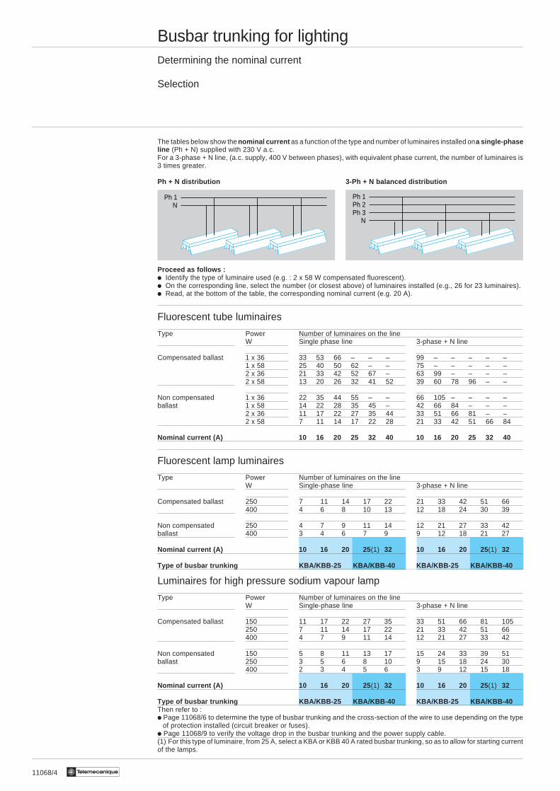
The tables below show the nominal current as a function of the type and number of luminaires installed on a single-phaseline (Ph + N) supplied with 230 V a.c.For a 3-phase + N line, (a.c. supply, 400 V between phases), with equivalent phase current, the number of luminaires is3 times greater.
Ph + N distribution 3-Ph + N balanced distribution
Proceed as follows :i Identify the type of luminaire used (e.g. : 2 x 58 W compensated fluorescent).i On the corresponding line, select the number (or closest above) of luminaires installed (e.g., 26 for 23 luminaires).i Read, at the bottom of the table, the corresponding nominal current (e.g. 20 A).
Fluorescent tube luminaires
Type Power Number of luminaires on the lineW Single phase line 3-phase + N line
Compensated ballast 1 x 36 33 53 66 – – – 99 – – – – –1 x 58 25 40 50 62 – – 75 – – – – –2 x 36 21 33 42 52 67 – 63 99 – – – –2 x 58 13 20 26 32 41 52 39 60 78 96 – –
Non compensated 1 x 36 22 35 44 55 – – 66 105 – – – –ballast 1 x 58 14 22 28 35 45 – 42 66 84 – – –
2 x 36 11 17 22 27 35 44 33 51 66 81 – –2 x 58 7 11 14 17 22 28 21 33 42 51 66 84
Nominal current (A) 10 16 20 25 32 40 10 16 20 25 32 40
Fluorescent lamp luminaires
Type Power Number of luminaires on the lineW Single-phase line 3-phase + N line
Compensated ballast 250 7 11 14 17 22 21 33 42 51 66400 4 6 8 10 13 12 18 24 30 39
Non compensated 250 4 7 9 11 14 12 21 27 33 42ballast 400 3 4 6 7 9 9 12 18 21 27
Nominal current (A) 10 16 20 25 (1) 32 10 16 20 25(1) 32
Type of busbar trunking KBA/KBB-25 KBA/KBB-40 KBA/KBB-25 KBA/KBB-40
Luminaires for high pressure sodium vapour lamp
Type Power Number of luminaires on the lineW Single-phase line 3-phase + N line
Compensated ballast 150 11 17 22 27 35 33 51 66 81 105250 7 11 14 17 22 21 33 42 51 66400 4 7 9 11 14 12 21 27 33 42
Non compensated 150 5 8 11 13 17 15 24 33 39 51ballast 250 3 5 6 8 10 9 15 18 24 30
400 2 3 4 5 6 3 9 12 15 18
Nominal current (A) 10 16 20 25 (1) 32 10 16 20 25(1) 32
Type of busbar trunking KBA/KBB-25 KBA/KBB-40 KBA/KBB-25 KBA/KBB-40Then refer to :i Page 11068/6 to determine the type of busbar trunking and the cross-section of the wire to use depending on the type
of protection installed (circuit breaker or fuses).i Page 11068/9 to verify the voltage drop in the busbar trunking and the power supply cable.(1) For this type of luminaire, from 25 A, select a KBA or KBB 40 A rated busbar trunking, so as to allow for starting currentof the lamps.
Ph 1Ph 2Ph 3
N
Ph 1N
11068/5Te
Busbar trunking for lightingProtection against overloads by precalculatingPRC or PVC cables + Canalis
Selection
Subjects from the Guide of Precalculated Projects and software (CanGEP, Ecodial, etc), the information in this chapterhelps to define trunking (cables and Canalis) and their protection, in complete conformity with the standard NF C 15-100and the UTE C15-500 calculation guide.
Protection of the main busbar trunking (cable + Canalis)
The following tables enable determination of :i The nominal current (In) or overload protection adjustment (Ir).i The Canalis nominal rating (Inc).i The minimum thermal cable cross-section.
These three characteristics are defined for the following installation conditions :i Ambient temperature 30 °C maximum.i Cables placed in cable routing or on panels. Layout as a single horizontal layer or in groups of 2 or 3 cores.
Tap-off protection
Tap-off outputs from Canalis must have an overload protection device. The tap-off is created using a fuse connector whichprotects the cable (C3) and the equipment, against short-circuits.This protection offers good discrimination during operation (continuity of service, troubleshooting, etc).
With lighting , it may be worth taking advantage of the possibilities for dispensing with or remotely locating theprotection, offered by the NFC 15-100 and summarised below (extracts from guide UTE C 15-107).The tap-off is created using a pre-wired connector.
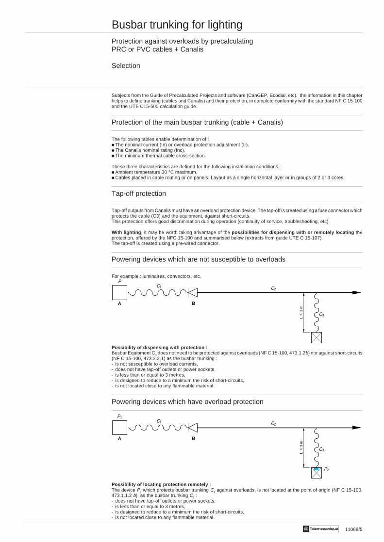
Powering devices which are not susceptible to overloads
For example : luminaires, convectors, etc.
Possibility of dispensing with protection :Busbar Equipment C3 does not need to be protected against overloads (NF C 15-100, 473.1.2b) nor against short-circuits(NF C 15-100, 473.2.2.1) as the busbar trunking :- is not susceptible to overload currents,- does not have tap-off outlets or power sockets,- is less than or equal to 3 metres,- is designed to reduce to a minimum the risk of short-circuits,- is not located close to any flammable material.
Powering devices which have overload protection
Possibility of locating protection remotely :The device P2 which protects busbar trunking C3 against overloads, is not located at the point of origin (NF C 15-100,473.1.1.2 b), as the busbar trunking C3 :- does not have tap-off outlets or power sockets,- is less than or equal to 3 metres,- is designed to reduce to a minimum the risk of short-circuits,- is not located close to any flammable material.
C1P1
C2
C3
P2
A B
L
3 m
PC1 C2
C3
A BL
3
m
11068/6 Te
Busbar trunking for lightingProtection against overloads by precalculatingPRC or PVC copper cables + Canalis
Selection
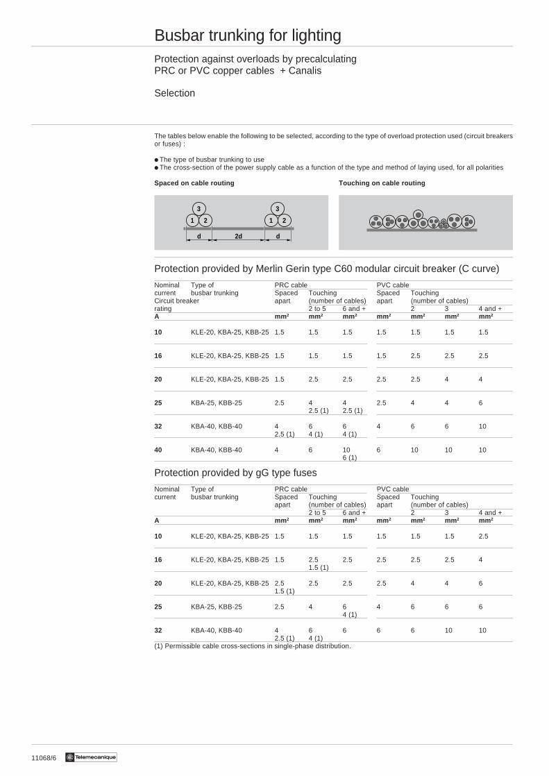
The tables below enable the following to be selected, according to the type of overload protection used (circuit breakersor fuses) :
i The type of busbar trunking to usei The cross-section of the power supply cable as a function of the type and method of laying used, for all polarities
Spaced on cable routing Touching on cable routing
Protection provided by Merlin Gerin type C60 modular circuit breaker (C curve)
Nominal Type of PRC cable PVC cablecurrent busbar trunking Spaced Touching Spaced TouchingCircuit breaker apart (number of cables) apart (number of cables)rating 2 to 5 6 and + 2 3 4 and +A mm 2 mm 2 mm 2 mm 2 mm 2 mm 2 mm 2
10 KLE-20, KBA-25, KBB-25 1.5 1.5 1.5 1.5 1.5 1.5 1.5
16 KLE-20, KBA-25, KBB-25 1.5 1.5 1.5 1.5 2.5 2.5 2.5
20 KLE-20, KBA-25, KBB-25 1.5 2.5 2.5 2.5 2.5 4 4
25 KBA-25, KBB-25 2.5 4 4 2.5 4 4 62.5 (1) 2.5 (1)
32 KBA-40, KBB-40 4 6 6 4 6 6 102.5 (1) 4 (1) 4 (1)
40 KBA-40, KBB-40 4 6 10 6 10 10 106 (1)
Protection provided by gG type fuses
Nominal Type of PRC cable PVC cablecurrent busbar trunking Spaced Touching Spaced Touching
apart (number of cables) apart (number of cables)2 to 5 6 and + 2 3 4 and +
A mm 2 mm 2 mm 2 mm 2 mm 2 mm 2 mm 2
10 KLE-20, KBA-25, KBB-25 1.5 1.5 1.5 1.5 1.5 1.5 2.5
16 KLE-20, KBA-25, KBB-25 1.5 2.5 2.5 2.5 2.5 2.5 41.5 (1)
20 KLE-20, KBA-25, KBB-25 2.5 2.5 2.5 2.5 4 4 61.5 (1)
25 KBA-25, KBB-25 2.5 4 6 4 6 6 64 (1)
32 KBA-40, KBB-40 4 6 6 6 6 10 102.5 (1) 4 (1)
(1) Permissible cable cross-sections in single-phase distribution.
1 2
3
1 2
3
d 2d d

11068/7Te
Busbar trunking for lightingWithstand to short-circuit currents
Selection
Determining the prospective short-circuit current at the origin of the Canalis
Two situations may be encountered :
1 - The lighting busbar trunking is powered from a secondary distribution board.
2 - The lighting busbar trunking is powered from another Canalis busbar trunking.
Isc (a) : Short-circuit rms current to transformer terminals.
Values of Isc (a) rms to transformer terminals (U = 400 V).Power (kVA) 50 100 160 200 250 315 400 500 630 800 1000 1250 1600Isc(a) (kA) 1.8 3.6 5.7 7.2 8.9 11.2 14.2 17.6 22.1 24.8 27.8 31.5 36.7
Isc (b) : Down stream short-circuit current, less than Isc(a), limited by the impedance of the cable.Isc (c) : Short-circuit current to the circuit breaker terminals, less than Isc(b), limited by the circuit breaker.Isc (d) : Prospective short-circuit current limited by the impedance of the cable (case 1), or of the cable + Canalis (case 2).Isc (e) : Prospective short-circuit current at the head of the Canalis trunking limited by the circuit breaker (d) and the
impedance of the Canalis power supply cable.
The various guides of precalculated projects and software (CanGEP, Ecodial, etc) published by Schneider are used toobtain a fast and precise evaluation of prospective short-circuit currents at different points in the circuit.Please consult your Regional Sales Office .
Note : The evaluation of short-circuit currents is not required for circuits protected by H.B.C. fuses (breaking capacityalways greater than or equal to 50 kA).
Canalis and protection coordination
Taken from the test relating to the standard (and used in our guides and software), the table below is used to determinethe type of Merlin Gerin circuit breaker or fuses to use for a particular type of busbar trunking, depending on the prospectiveshort-circuit current at the head of the Canalis trunking.
Type of Protection via circuit breaker Protection via fusesbusbar trunking Isc (d) (prospective Isc) Prospective Isc (kA)
10 kA 15 kA 20 kA 25 kA 50 kA 50 kAKLE-20 C60N20 C60H20 C60L20 C60L20 — 20 A gGKBA-25, KBB-25 C60N25 C60H25 C60L25 C60L25 NC100LH25 20 A gGKBA-40, KBB-40 C60N40 C60H40 C60L40 C60L40 NC100LH40 32 A gG
Characteristics of Canalis busbar trunking
Type of Resistance to short-circuit currents Permissiblebusbar trunking Permissible rated rms current thermal
peak current (cos ϕ = 0.7) constraintkA kA A 2s
KLE-20 4.4 2.9 19.5 . 104
KBA-25 4.4 2.9 19.5 . 104
KBA-40 9.6 6.4 90 . 104
KBB-25 4.4 2.9 19.5 . 104
KBB-40 9.6 6.4 90 . 104
Isc (a) Isc (b) Isc (c)
ProspectiveIsc (d)Cable Canalis
Isc (a) Isc (b) Isc (c) Cable Canalis KN or KS
ProspectiveIsc (d)
CanalisKLE, KBAor KBB
ProspectiveIsc (e)

11068/8 Te
Busbar trunking for lightingVerifying the voltage drop
Selection
Recommended evaluation
i Attribute, for each circuit, a voltage drop expressed as a % of the nominal voltage (Un), bearing in mind that the voltagedrop between the origin and any point of use must not exceed that shown below.(NF C 15-100 - Requirements - Chapter 524-07-77).
Type of installation Voltage drop (for lighting)
Installations powered directly from a low voltage public distribution 3 %network.
Installations supplied by a subscriber station or via 6 %a transformer from a high voltage installation (1).
i Convert to volts the percentage of the nominal voltage (Un) attributed to each circuit.
i Using the tables, check that the busbar trunking and/or cables selected from the previous pages are compatible withthe calculated voltage drops.If not, increase the cross-section of the cables.
Notes- In a mixed circuit, the most economical choice consists of increasing the cable cross-section and avoiding the use of
prefabricated trunking for higher nominal current (Inc).- For certain loads, it may be necessary to take into account a transient voltage drop.
(1) If possible, the voltage drops in the lighting terminal circuits must not be greater than 3 %. When the main trunkinglength of the installation is longer than 100 m, these voltage drops can be increased by 0.005 % per metre of trunkingabove 100 m but, nevertheless, this addition must not exceed 0.5 %.
% Un
% Un
% Un
11068/9Te
Busbar trunking for lightingVerifying the voltage drop
Selection
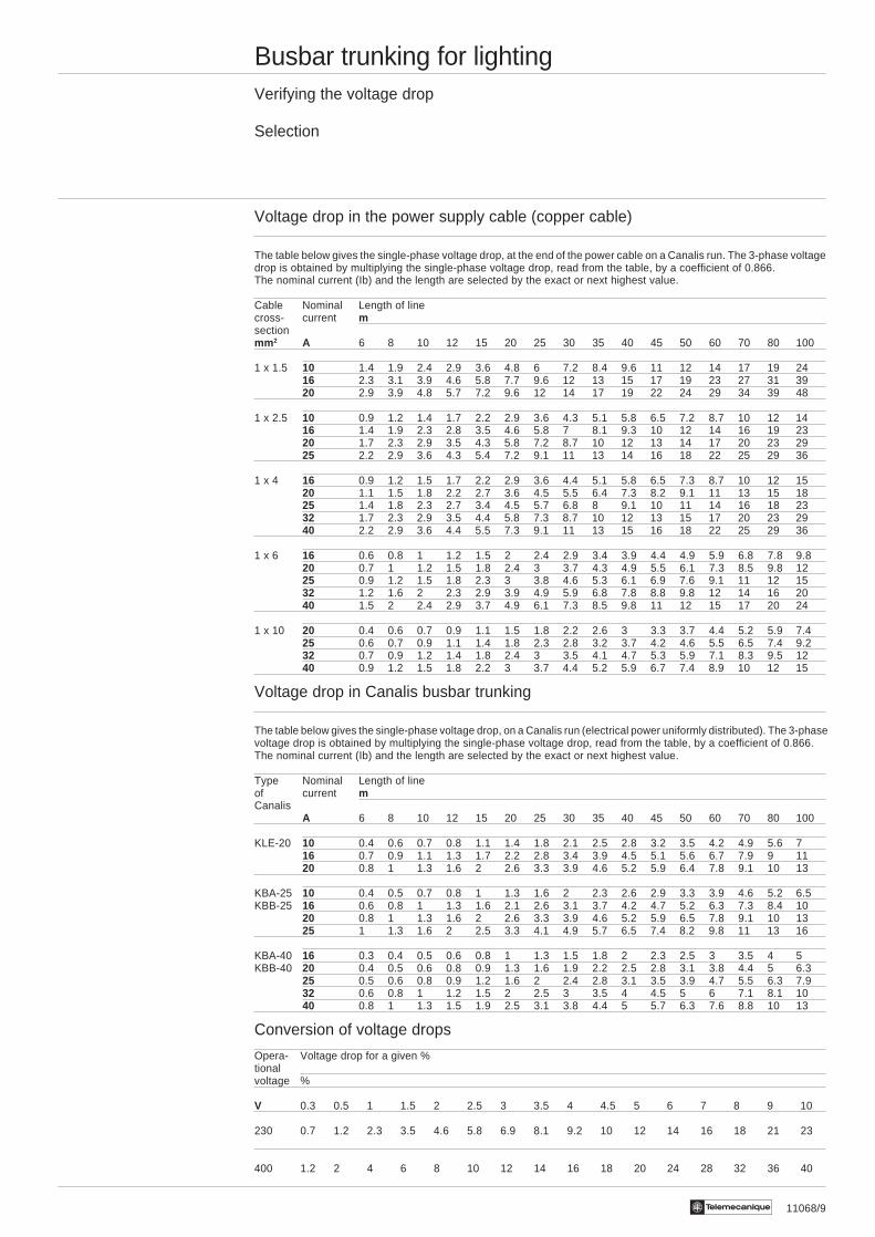
Voltage drop in the power supply cable (copper cable)
The table below gives the single-phase voltage drop, at the end of the power cable on a Canalis run. The 3-phase voltagedrop is obtained by multiplying the single-phase voltage drop, read from the table, by a coefficient of 0.866.The nominal current (Ib) and the length are selected by the exact or next highest value.
Cable Nominal Length of linecross- current msectionmm 2 A 6 8 10 12 15 20 25 30 35 40 45 50 60 70 80 100
1 x 1.5 10 1.4 1.9 2.4 2.9 3.6 4.8 6 7.2 8.4 9.6 11 12 14 17 19 2416 2.3 3.1 3.9 4.6 5.8 7.7 9.6 12 13 15 17 19 23 27 31 3920 2.9 3.9 4.8 5.7 7.2 9.6 12 14 17 19 22 24 29 34 39 48
1 x 2.5 10 0.9 1.2 1.4 1.7 2.2 2.9 3.6 4.3 5.1 5.8 6.5 7.2 8.7 10 12 1416 1.4 1.9 2.3 2.8 3.5 4.6 5.8 7 8.1 9.3 10 12 14 16 19 2320 1.7 2.3 2.9 3.5 4.3 5.8 7.2 8.7 10 12 13 14 17 20 23 2925 2.2 2.9 3.6 4.3 5.4 7.2 9.1 11 13 14 16 18 22 25 29 36
1 x 4 16 0.9 1.2 1.5 1.7 2.2 2.9 3.6 4.4 5.1 5.8 6.5 7.3 8.7 10 12 1520 1.1 1.5 1.8 2.2 2.7 3.6 4.5 5.5 6.4 7.3 8.2 9.1 11 13 15 1825 1.4 1.8 2.3 2.7 3.4 4.5 5.7 6.8 8 9.1 10 11 14 16 18 2332 1.7 2.3 2.9 3.5 4.4 5.8 7.3 8.7 10 12 13 15 17 20 23 2940 2.2 2.9 3.6 4.4 5.5 7.3 9.1 11 13 15 16 18 22 25 29 36
1 x 6 16 0.6 0.8 1 1.2 1.5 2 2.4 2.9 3.4 3.9 4.4 4.9 5.9 6.8 7.8 9.820 0.7 1 1.2 1.5 1.8 2.4 3 3.7 4.3 4.9 5.5 6.1 7.3 8.5 9.8 1225 0.9 1.2 1.5 1.8 2.3 3 3.8 4.6 5.3 6.1 6.9 7.6 9.1 11 12 1532 1.2 1.6 2 2.3 2.9 3.9 4.9 5.9 6.8 7.8 8.8 9.8 12 14 16 2040 1.5 2 2.4 2.9 3.7 4.9 6.1 7.3 8.5 9.8 11 12 15 17 20 24
1 x 10 20 0.4 0.6 0.7 0.9 1.1 1.5 1.8 2.2 2.6 3 3.3 3.7 4.4 5.2 5.9 7.425 0.6 0.7 0.9 1.1 1.4 1.8 2.3 2.8 3.2 3.7 4.2 4.6 5.5 6.5 7.4 9.232 0.7 0.9 1.2 1.4 1.8 2.4 3 3.5 4.1 4.7 5.3 5.9 7.1 8.3 9.5 1240 0.9 1.2 1.5 1.8 2.2 3 3.7 4.4 5.2 5.9 6.7 7.4 8.9 10 12 15
Voltage drop in Canalis busbar trunking
The table below gives the single-phase voltage drop, on a Canalis run (electrical power uniformly distributed). The 3-phasevoltage drop is obtained by multiplying the single-phase voltage drop, read from the table, by a coefficient of 0.866.The nominal current (Ib) and the length are selected by the exact or next highest value.
Type Nominal Length of lineof current mCanalis
A 6 8 10 12 15 20 25 30 35 40 45 50 60 70 80 100
KLE-20 10 0.4 0.6 0.7 0.8 1.1 1.4 1.8 2.1 2.5 2.8 3.2 3.5 4.2 4.9 5.6 716 0.7 0.9 1.1 1.3 1.7 2.2 2.8 3.4 3.9 4.5 5.1 5.6 6.7 7.9 9 1120 0.8 1 1.3 1.6 2 2.6 3.3 3.9 4.6 5.2 5.9 6.4 7.8 9.1 10 13
KBA-25 10 0.4 0.5 0.7 0.8 1 1.3 1.6 2 2.3 2.6 2.9 3.3 3.9 4.6 5.2 6.5KBB-25 16 0.6 0.8 1 1.3 1.6 2.1 2.6 3.1 3.7 4.2 4.7 5.2 6.3 7.3 8.4 10
20 0.8 1 1.3 1.6 2 2.6 3.3 3.9 4.6 5.2 5.9 6.5 7.8 9.1 10 1325 1 1.3 1.6 2 2.5 3.3 4.1 4.9 5.7 6.5 7.4 8.2 9.8 11 13 16
KBA-40 16 0.3 0.4 0.5 0.6 0.8 1 1.3 1.5 1.8 2 2.3 2.5 3 3.5 4 5KBB-40 20 0.4 0.5 0.6 0.8 0.9 1.3 1.6 1.9 2.2 2.5 2.8 3.1 3.8 4.4 5 6.3
25 0.5 0.6 0.8 0.9 1.2 1.6 2 2.4 2.8 3.1 3.5 3.9 4.7 5.5 6.3 7.932 0.6 0.8 1 1.2 1.5 2 2.5 3 3.5 4 4.5 5 6 7.1 8.1 1040 0.8 1 1.3 1.5 1.9 2.5 3.1 3.8 4.4 5 5.7 6.3 7.6 8.8 10 13
Conversion of voltage drops
Opera- Voltage drop for a given %tionalvoltage %
V 0.3 0.5 1 1.5 2 2.5 3 3.5 4 4.5 5 6 7 8 9 10
230 0.7 1.2 2.3 3.5 4.6 5.8 6.9 8.1 9.2 10 12 14 16 18 21 23
400 1.2 2 4 6 8 10 12 14 16 18 20 24 28 32 36 40
11068/10 Te
Busbar trunking for lightingStudy guide
Study example
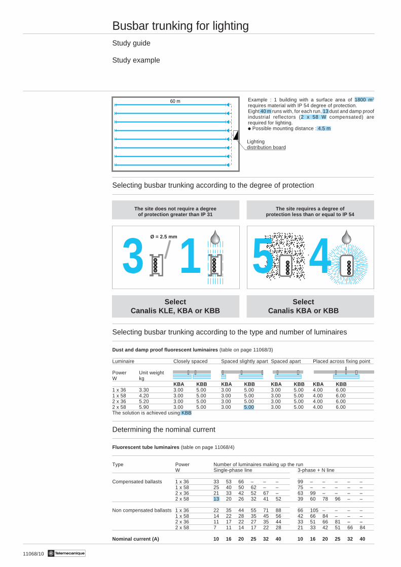
Example : 1 building with a surface area of 1800 m2
requires material with IP 54 degree of protection.Eight 40 m runs with, for each run, 13 dust and damp proofindustrial reflectors (2 x 58 W compensated) arerequired for lighting.i Possible mounting distance : 4.5 m
Selecting busbar trunking according to the degree of protection
The site does not require a degree The site requires a degree ofof protection greater than IP 31 protection less than or equal to IP 54
Select SelectCanalis KLE, KBA or KBB Canalis KBA or KBB
Selecting busbar trunking according to the type and number of luminaires
Dust and damp proof fluorescent luminaires (table on page 11068/3)
Luminaire Closely spaced Spaced slightly apart Spaced apart Placed across fixing point
Power Unit weightW kg
KBA KBB KBA KBB KBA KBB KBA KBB1 x 36 3.30 3.00 5.00 3.00 5.00 3.00 5.00 4.00 6.001 x 58 4.20 3.00 5.00 3.00 5.00 3.00 5.00 4.00 6.002 x 36 5.20 3.00 5.00 3.00 5.00 3.00 5.00 4.00 6.002 x 58 5.90 3.00 5.00 3.00 5.00 3.00 5.00 4.00 6.00The solution is achieved using KBB
Determining the nominal current
Fluorescent tube luminaires (table on page 11068/4)
Type Power Number of luminaires making up the runW Single-phase line 3-phase + N line
Compensated ballasts 1 x 36 33 53 66 – – – 99 – – – – –1 x 58 25 40 50 62 – – 75 – – – – –2 x 36 21 33 42 52 67 – 63 99 – – – –2 x 58 13 20 26 32 41 52 39 60 78 96 – –
Non compensated ballasts 1 x 36 22 35 44 55 71 88 66 105 – – – –1 x 58 14 22 28 35 45 56 42 66 84 – – –2 x 36 11 17 22 27 35 44 33 51 66 81 – –2 x 58 7 11 14 17 22 28 21 33 42 51 66 84
Nominal current (A) 10 16 20 25 32 40 10 16 20 25 32 40
13 45
Lightingdistribution board
Ø = 2.5 mm
60 m
11068/11Te
Busbar trunking for lightingStudy guide
Study example
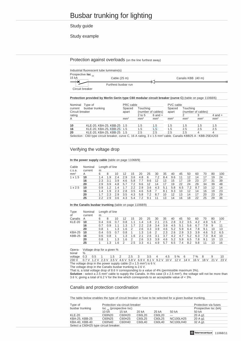
Protection against overloads (on the line furthest away)
Industrial fluorescent tube luminaire(s)
Protection provided by Merlin Gerin type C60 modular circuit breaker (curve C) (table on page 11068/6)
Nominal Type of PRC cable PVC cablecurrent busbar trunking Spaced Touching Spaced TouchingCircuit breaker apart (number of cables) apart (number of cables)rating 2 to 5 6 and + 2 3 4 and +A mm2 mm2 mm2 mm2 mm2 mm2 mm2
10 KLE-20, KBA-25, KBB-25 1.5 1.5 1.5 1.5 1.5 1.5 1.516 KLE-20, KBA-25, KBB-25 1.5 1.5 1.5 1.5 2.5 2.5 2.520 KLE-20, KBA-25, KBB-25 1.5 2.5 2.5 2.5 2.5 4 4Selection : C60 type circuit breaker, curve C, 16 A rating, 3 x 1.5 mm2 cable. Canalis KBB25 A : KBB-25EA203
Verifying the voltage drop
In the power supply cable (table on page 11068/9)
Cable Nominal Length of linec.s.a. current mmm2 A 6 8 10 12 15 20 25 30 35 40 45 50 60 70 80 1001 x 1.5 10 1.4 1.9 2.4 2.9 3.6 4.8 6 7.2 8.4 9.6 11 12 14 17 19 24
16 2.3 3.1 3.9 4.6 5.8 7.7 9.6 12 13 15 17 19 23 27 31 3920 2.9 3.9 4.8 5.7 7.2 9.6 12 14 17 19 22 24 29 34 39 48
1 x 2.5 10 0.9 1.2 1.4 1.7 2.2 2.9 3.6 4.3 5.1 5.8 6.5 7.2 8.7 10 12 1416 1.4 1.9 2.3 2.8 3.5 4.6 5.8 7 8.1 9.3 10 12 14 16 19 2320 1.7 2.3 2.9 3.5 4.3 5.8 7.2 8.7 10 12 13 14 17 20 23 2925 2.2 2.9 3.6 4.3 5.4 7.2 9.1 11 13 14 16 18 22 25 29 36
In the Canalis busbar trunking (table on page 11068/9)
Type Nominal Length of lineof current mCanalis A 6 8 10 12 15 20 25 30 35 40 45 50 60 70 80 100KLE-20 10 0.4 0.6 0.7 0.8 1.1 1.4 1.8 2.1 2.5 2.8 3.2 3.5 4.2 4.9 5.6 7
16 0.7 0.9 1.1 1.3 1.7 2.2 2.8 3.4 3.9 4.5 5.1 5.6 6.7 7.9 9 1120 0.8 1 1.3 1.6 2 2.6 3.3 3.9 4.6 5.2 5.9 6.4 7.8 9.1 10 13
KBA-25 10 0.4 0.5 0.7 0.8 1 1.3 1.6 2 2.3 2.6 2.9 3.3 3.9 4.6 5.2 6.5KBB-25 16 0.6 0.8 1 1.3 1.6 2.1 2.6 3.1 3.7 4.2 4.7 5.2 6.3 7.3 8.4 10
20 0.8 1 1.3 1.6 2 2.6 3.3 3.9 4.6 5.2 5.9 6.5 7.8 9.1 10 1325 1 1.3 1.6 2 2.5 3.3 4.1 4.9 5.7 6.5 7.4 8.2 9.8 11 13 16
Opera- Voltage drop for a given %tional %voltage 0.3 0.5 1 1.5 2 2.5 3 3.5 4 4.5 5 % 6 7 % 8 9 10230 V 0.7 V 1.2 V 2.3 V 3.5 V 4.6 V 5.8 V 6.9 V 8.1 V 9.2 V 10 V 12 V 14 V 16 V 18 V 21 V 23 VThe voltage drop in the power supply cable (3 x 1.5 mm2) is 6 V.The voltage drop in the Canalis busbar trunking is 2.6 V.That is, a total voltage drop of 8.6 V corresponding to a value of 4% (permissible maximum 3%).Solution : select a 2.5 mm2 cable to supply the Canalis. In this case (3 x 2.5 mm2), the voltage will not be more than3.6 V, giving a total of 6.2 V for the line which corresponds to an acceptable value of < 3%.
Canalis and protection coordination
The table below enables the type of circuit breaker or fuse to be selected for a given busbar trunking.
Type of Protection via circuit breaker Protection via fusesbusbar trunking Isc (d) (prospective Isc) Prospective Isc (kA)
10 kA 15 kA 20 kA 25 kA 50 kA 50 kAKLE-20 C60N20 C60H20 C60L20 C60L20 — 20 A g1KBA-25, KBB-25 C60N25 C60H25 C60L25 C60L25 NC100LH25 20 A g1KBA-40, KBB-40 C60N40 C60H40 C60L40 C60L40 NC100LH40 32 A g1Select a C60H25 type circuit breaker.
Canalis KBB (40 m)Cable (25 m)
Furthest busbar runCircuit breaker
Prospective Isc (d)15 kA
11075/2 Te
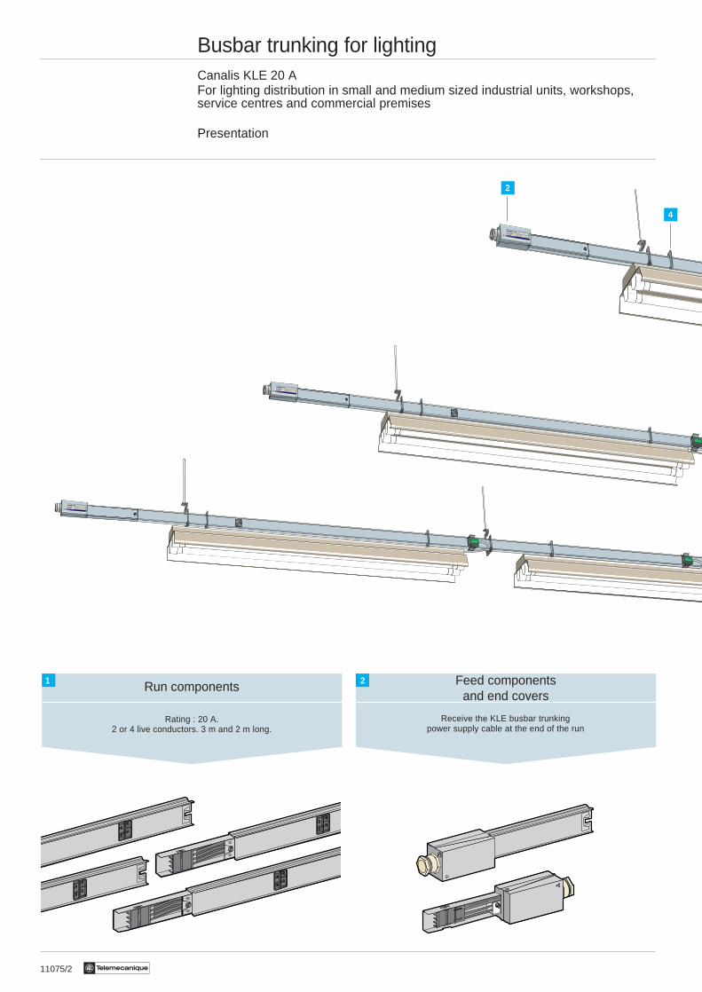
Busbar trunking for lightingCanalis KLE 20 AFor lighting distribution in small and medium sized industrial units, workshops,service centres and commercial premises
Presentation
Rating : 20 A.2 or 4 live conductors. 3 m and 2 m long.
Run components1
Receive the KLE busbar trunkingpower supply cable at the end of the run
2
4
Feed componentsand end covers
2
11075/3Te
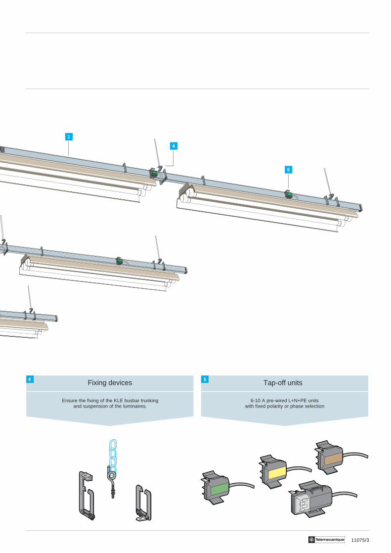
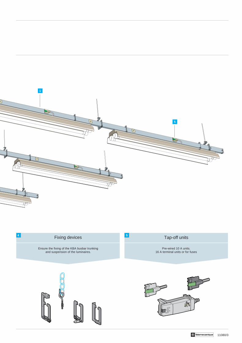
Fixing devices
Ensure the fixing of the KLE busbar trunkingand suspension of the luminaires.
4 Tap-off units
6-10 A pre-wired L+N+PE unitswith fixed polarity or phase selection
5
1
5
4
11076/2 Te
Busbar trunking for lightingCanalis KLE 20 A
Description
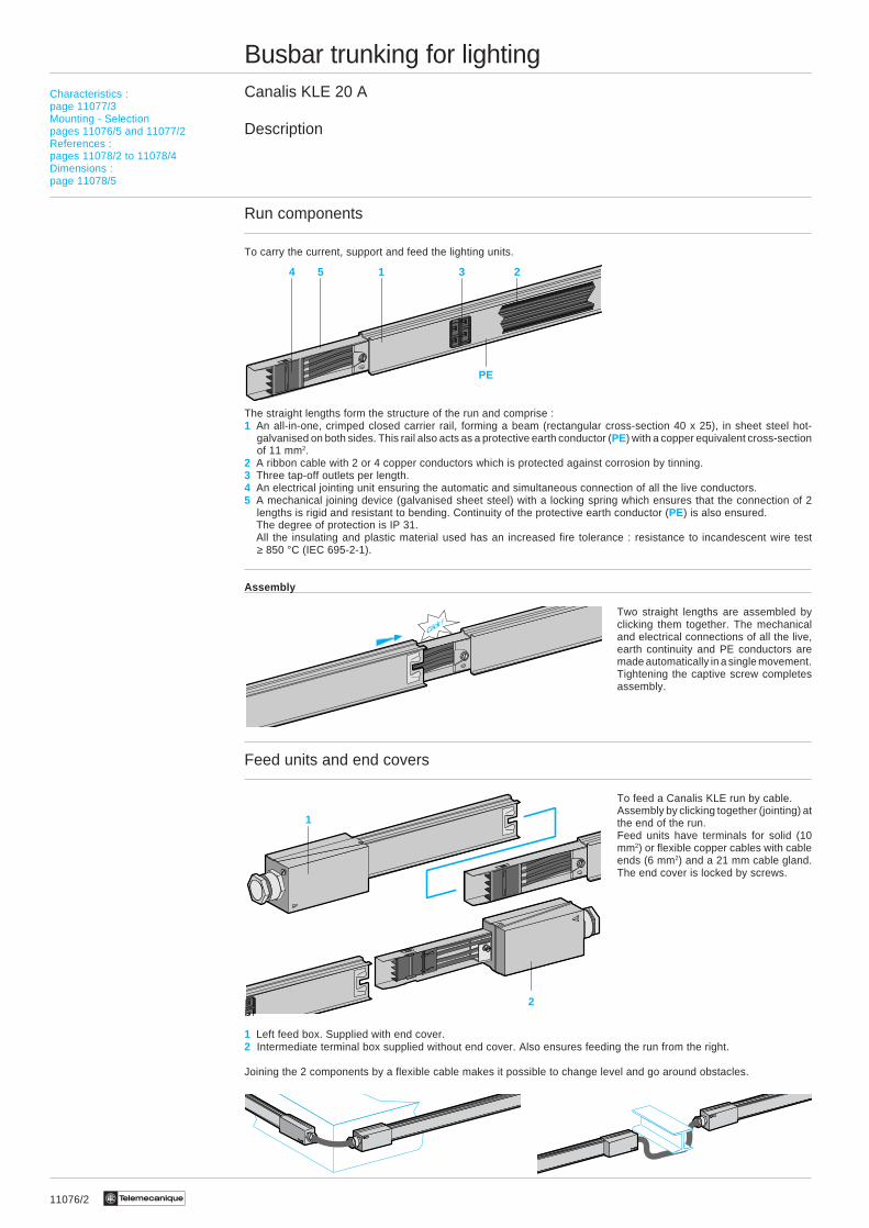
Run components
To carry the current, support and feed the lighting units.
The straight lengths form the structure of the run and comprise :1 An all-in-one, crimped closed carrier rail, forming a beam (rectangular cross-section 40 x 25), in sheet steel hot-
galvanised on both sides. This rail also acts as a protective earth conductor (PE) with a copper equivalent cross-sectionof 11 mm2.
2 A ribbon cable with 2 or 4 copper conductors which is protected against corrosion by tinning.3 Three tap-off outlets per length.4 An electrical jointing unit ensuring the automatic and simultaneous connection of all the live conductors.5 A mechanical joining device (galvanised sheet steel) with a locking spring which ensures that the connection of 2
lengths is rigid and resistant to bending. Continuity of the protective earth conductor (PE) is also ensured.The degree of protection is IP 31.All the insulating and plastic material used has an increased fire tolerance : resistance to incandescent wire test≥ 850 °C (IEC 695-2-1).
Assembly
Two straight lengths are assembled byclicking them together. The mechanicaland electrical connections of all the live,earth continuity and PE conductors aremade automatically in a single movement.Tightening the captive screw completesassembly.
Feed units and end covers
To feed a Canalis KLE run by cable.Assembly by clicking together (jointing) atthe end of the run.Feed units have terminals for solid (10mm2) or flexible copper cables with cableends (6 mm2) and a 21 mm cable gland.The end cover is locked by screws.
1 Left feed box. Supplied with end cover.2 Intermediate terminal box supplied without end cover. Also ensures feeding the run from the right.
Joining the 2 components by a flexible cable makes it possible to change level and go around obstacles.
Characteristics :page 11077/3Mounting - Selectionpages 11076/5 and 11077/2References :pages 11078/2 to 11078/4Dimensions :page 11078/5
2
1
4 5 1 3 2
PE
Click !
11076/3Te
Busbar trunking for lightingCanalis KLE 20 A
Description
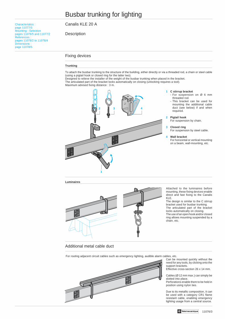
Fixing devices
Trunking
To attach the busbar trunking to the structure of the building, either directly or via a threaded rod, a chain or steel cable(using a pigtail hook or closed ring for the latter two).Designed to relieve the installer of the weight of the busbar trunking when placed in the bracket.The articulated part of the bracket locks automatically on closing (unlocking requires a tool).Maximum advised fixing distance : 3 m.
1 C stirrup bracket- For suspension on Ø 6 mm
threaded rod.- This bracket can be used for
mounting the additional cableduct (see below) if and whenrequired.
2 Pigtail hookFor suspension by chain.
3 Closed ringFor suspension by steel cable.
4 Wall bracketFor horizontal or vertical mountingon a beam, wall-mounting, etc.
Luminaires
Attached to the luminaires beforemounting, these fixing devices enabledirect and fast fixing to the CanalisKLE.The design is similar to the C stirrupbracket used for busbar trunking.The articulated part of the bracketlocks automatically on closing.The use of an open hook and/or closedring allows mounting suspended by achain, etc.
Additional metal cable duct
For routing adjacent circuit cables such as emergency lighting, audible alarm cables, etc.Can be mounted quickly without theneed for any tools, by clicking onto thesupport brackets.Effective cross-section 26 x 14 mm.
Cables (Ø 12 mm max.) can simply beslotted into place.Perforations enable them to be held inposition using nylon ties.
Due to its metallic composition, it canbe used with a category CR1 flameresistant cable, enabling emergencylighting usage from a central source.
1
2 3 4
Characteristics :page 11077/3Mounting - Selectionpages 11076/5 and 11077/2References :pages 11078/2 to 11078/4Dimensions :page 11078/5

11076/4 Te
1 1 1
Busbar trunking for lightingCanalis KLE 20 A
Description
Tap-off units
For instant connection of lighting equipment to the Canalis KL run.
i They are always 2-poleL + N + PE.
i They can be handled when poweredup and under load.
i The live conductor contacts are cliptype (with no pressure on theplastic).
i They are provided with an inter-locking device preventing incorrectconnection.
i The PE connection is establishedbefore the phase or neutralconnection, on the internal panelcasing of the straight length.
i The body and all the insulation partshave an increased fire resistance :resistance to incandescent wire test≥ 850 °C (IEC 695-2-1).
1 Casing2 Attachment foot3 Live conductor contacts4 Protective conductor contacts5 Displays the phase selected
i By the colour of the centre (fixedpolarity connector)
i By the transparent window (phaseselection connector)
2-pole pre-wired units
Pre-wired with H05VV-F cable, 3 x 1 mm2. The end of the cable, where the luminaire is connected, is pre-stripped.
1 6 A unit, fixed polarity, cable length0.6 m
They can be identified from adistance by the colour at the centreof the connector :- green L1/N- yellow L2/N- brown L3/N
2 10 A unit, L + N with phaseselection, cable length 0.8 m or 2 m.
L1, L2 or L3
Choix :page 11003/2Caractéristiques :page 11003/3Références :pages 11004/3 et 11005/2Encombrements :page 11005/3
4
4 3
512
125
2
Characteristics :page 11077/3Mounting - Selectionpages 11076/5 and 11077/2References :pages 11078/2 to 11078/4Dimensions :page 11078/5
11076/5Te
1
3
2
4
4
Click !
Busbar trunking for lightingCanalis KLE 20 A
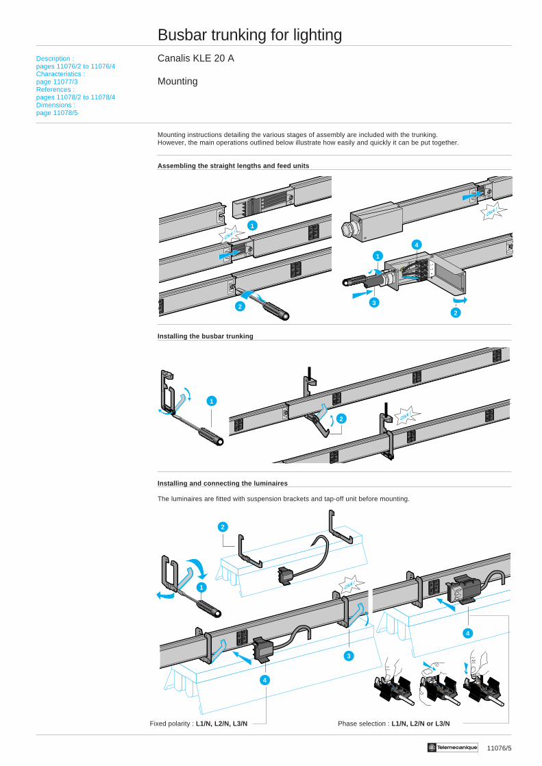
Mounting
Mounting instructions detailing the various stages of assembly are included with the trunking.However, the main operations outlined below illustrate how easily and quickly it can be put together.
Assembling the straight lengths and feed units
Installing the busbar trunking
Installing and connecting the luminaires
The luminaires are fitted with suspension brackets and tap-off unit before mounting.
Choix :page 11003/2Caractéristiques :page 11003/3Références :pages 11004/3 et 11005/2Encombrements :page 11005/3
Description :pages 11076/2 to 11076/4Characteristics :page 11077/3References :pages 11078/2 to 11078/4Dimensions :page 11078/5
Fixed polarity : L1/N, L2/N, L3/N Phase selection : L1/N, L2/N or L3/N
Click !1
2
Click !
L 2
L 1
L 3
N
1
2
3
4
Click !
1
2

11077/2 Te
Busbar trunking for lightingCanalis KLE 20 A
Selection
You have selected KLE
Know :i The type of luminaire (types of lamp, power,compensated or not), its weight, number and distributioni The structure of the premises (option of mountingbusbar trunking)i External influences (IP degree required)Otherwise :See the selection and study guide pages : 0120Q/2 and1068/2 to 11.
Selecting the busbar trunking
KLE busbar trunking has a single 20 A rating.Selection of the polarity depends on the power drawn per phase and/or the number of lighting circuits.By distributing the total load, the distribution by 3 L + N busbar trunking :i either limits the operating current lb : ⇒ limits the voltage drop,i or creates 2 or 3 lighting circuits : ⇒ modulates the level of lighting and energy saving.
Busbar trunking with 2 live conductors : L + N + PE Busbar trunking with 4 live conductors : 3L + N + PE
Application ⇒ Single light circuit distribution Application ⇒ Luminaires balanced on 3 phases ⇒ 3 light circuit distribution
Note : For i 3L (no N) distribution (3 X 230 V)i 2 single phase circuits L + N distribution Change your selection to Canalis KBA busbar trunking. on busbar trunking with 4 conductorsi tap-offs on 3L + N receivers
Fixing the busbar trunking
The normal position for mounting is edgewise. For flat mounting, please consult your Regional Sales Office.The fixing distance depends on the weight of the luminaires suspended between 2 fixing points and must not exceed 3 metres.
Suspended mounting : KLE-40ZA2 Edge mounting : KLE-40ZA4
Tap-off units
Tap-off units are always single-phase : L + N (fixed) + PE and pre-wired with H05VVF 3 X 1 mm2.The choice of unit depends on the type of lighting equipment :
- for tube lighting with higher cable entry and central - for any type of lighting.terminal block.KLC-06CS2ii 6 A, fixed polarity, pre-wired, 0.6 m long. KLC-10CC21i 10 A, with phase selection,
pre-wired, 0.80 or 2 m long.
Additional cable duct
The KBB-40ZG2 additional cable duct can be assembledduring or after the main installation.3 x 3 m KLE-40ZG1 support brackets are required.
Choix :page 11003/2Caractéristiques :page 11003/3Références :pages 11004/3 et 11005/2Encombrements :page 11005/3
Description :pages 11076/2 to 11076/4Characteristics :page 11077/5References :pages 11078/2 to 11078/4Dimensions :page 11078/5
3 m max.
1.25 m1.25 m1
N
L
PE
N
L2L1L3
PE
2
Click !

11077/3Te
Busbar trunking for lightingCanalis KLE 20 A
Characteristics
Type of busbar trunking KLE-20
General electrical characteristics
Conformity to standards IEC 439-2 and EN 60439-2
Number of live conductors 2 or 4Inc (average ambient
Rated nominal current temperature 35 °C) A 20
Type of current/ rated frequency F Hz c 50/60
Rated insulation voltage Ui V 500
Rated operating voltage Ue V 230...400
Degree of protection conforming to IEC 529 IP 31
Electrical characteristics of conductors
Live conductors R20 or Rb0 ph (1) average resistance, cold state mΩ/m 6.83(per conductor) (ambient temperature 20 °C)
R1 or Rb1 ph (1) average resistance at Inc mΩ/m 7.93(ambient temperature 35 °C)
X1 or Xb ph (1) average reactance at Inc mΩ/m 0.21and at 50 Hz rated frequency
Protective conductor Average resistance, cold state mΩ/m 1.57(ambient temperature 20 °C)
Fault loop characteristics
Average loop resistance Rb1 ph ph or ph N (at thermal mΩ/m 15.86between live conductors stabilisation temperature θ 1)
Rb2 ph ph or ph N (1) (at conventional mΩ/m 19.03short-circuit temperature)
Average loop reactance Xb ph ph mΩ/m 1.68
Xb ph N mΩ/m 2.08
Average loop resistance Rb1 ph PE (at thermal mΩ/m 9.90between live and PE conductors stabilisation temperature θ 1)
Rb2 ph PE (1) (at conventional mΩ/m 11.88short-circuit temperature)
Average loop reactance Xb ph PE mΩ/m 1.30
Other characteristics
Short-circuit current Ipk permissible rated peak current kA 4.40withstand I2t maximum thermal limit A2s 195.103
Voltage drop Voltage drop, for single-phase current 50 Hz, in volts per 100 m and per ampere with loads evenly distributedalong the run (general case for lighting).Voltage drop for 3-phase : multiply these values by 0.866.For Cos.ϕ = 0.8 V/100m/A 0.65For Cos.ϕ = 0.9 V/100m/A 0.72For Cos.ϕ = 1 V/100m/A 0.79
Normal mounting position Edgewise
Permissible current depending k1 uprating/derating multiplying factor to be applied to the desired rated current Inc of the busbar trunking for an averageon the temperature daily ambient temperature different to 35 °C.
Ambient temperature °C 15 20 25 30 35 40 45 50k1 factor 1.13 1.10 1.07 1.04 1.00 0.96 0.93 0.89
(1) In accordance with CENELEC document RO 64-003.
Description :pages 11002/2 à 11002/5Choix :page 11003/2Références :pages 11004/3 et 11005/2Encombrements :page 11005/3
Description :pages 11076/2 to 11076/4Mounting - Selectionpages 11076/5 and 11077/2References :pages 11078/2 to 11078/4Dimensions :page 11078/5
11078/2 Te
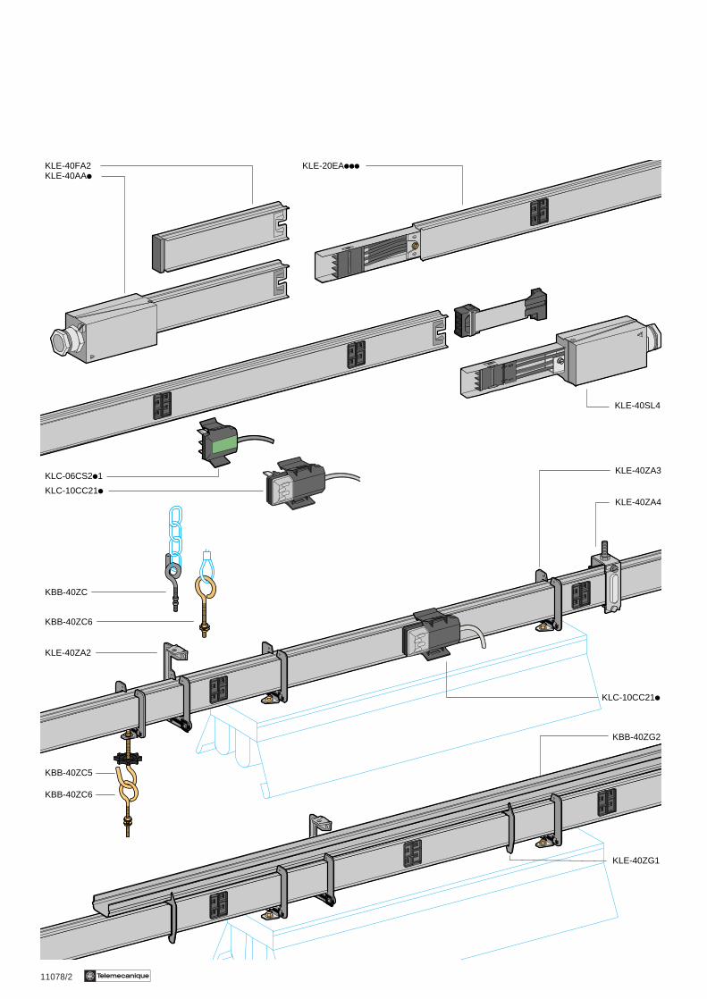
KLE-20EAiii
KLC-06CS2i1
KLC-10CC21iKLE-40ZA4
KLE-40ZA3
KLC-10CC21i
KBB-40ZG2
KLE-40ZG1
KLE-40SL4
KLE-40FA2KLE-40AAi
KBB-40ZC
KBB-40ZC6
KLE-40ZA2
KBB-40ZC5
KBB-40ZC6
11078/3Te
Busbar trunking for lightingCanalis KLE 20 A
References
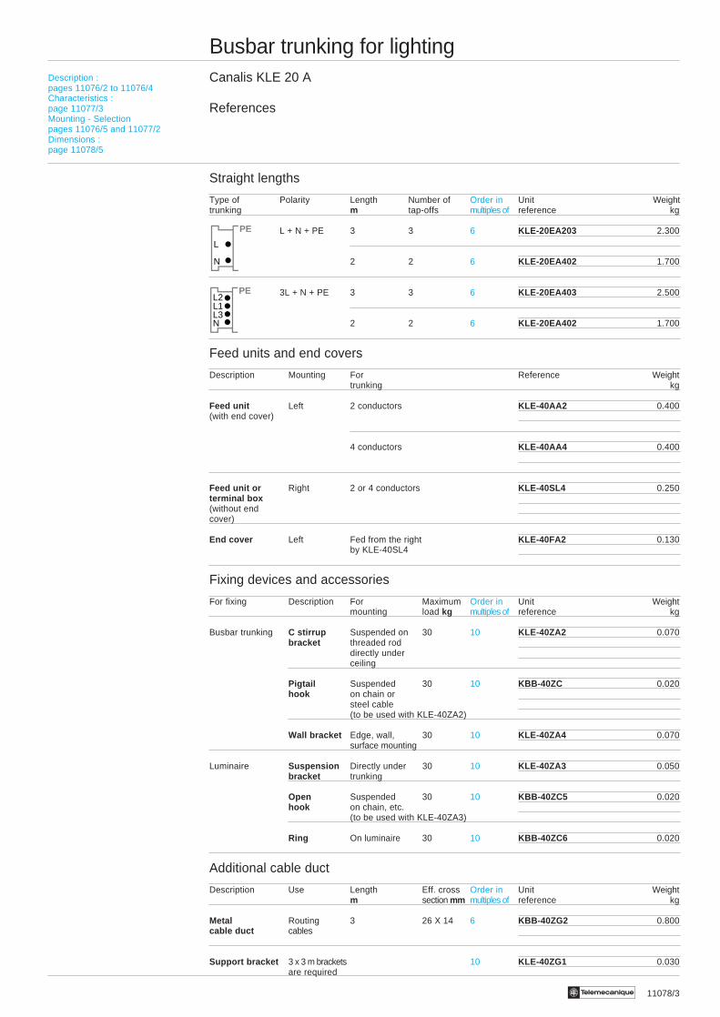
Straight lengths
Type of Polarity Length Number of Order in Unit Weighttrunking m tap-offs multiples of reference kg
L + N + PE 3 3 6 KLE-20EA203 2.300
2 2 6 KLE-20EA402 1.700
3L + N + PE 3 3 6 KLE-20EA403 2.500
2 2 6 KLE-20EA402 1.700
Feed units and end covers
Description Mounting For Reference Weighttrunking kg
Feed unit Left 2 conductors KLE-40AA2 0.400(with end cover)
4 conductors KLE-40AA4 0.400
Feed unit or Right 2 or 4 conductors KLE-40SL4 0.250terminal box(without endcover)
End cover Left Fed from the right KLE-40FA2 0.130by KLE-40SL4
Fixing devices and accessories
For fixing Description For Maximum Order in Unit Weightmounting load kg multiples of reference kg
Busbar trunking C stirrup Suspended on 30 10 KLE-40ZA2 0.070bracket threaded rod
directly underceiling
Pigtail Suspended 30 10 KBB-40ZC 0.020hook on chain or
steel cable(to be used with KLE-40ZA2)
Wall bracket Edge, wall, 30 10 KLE-40ZA4 0.070surface mounting
Luminaire Suspension Directly under 30 10 KLE-40ZA3 0.050bracket trunking
Open Suspended 30 10 KBB-40ZC5 0.020hook on chain, etc.
(to be used with KLE-40ZA3)
Ring On luminaire 30 10 KBB-40ZC6 0.020
Additional cable duct
Description Use Length Eff. cross Order in Unit Weightm section mm multiples of reference kg
Metal Routing 3 26 X 14 6 KBB-40ZG2 0.800cable duct cables
Support bracket 3 x 3 m brackets 10 KLE-40ZG1 0.030are required
Description :pages 11076/2 to 11076/4Characteristics :page 11077/3Mounting - Selectionpages 11076/5 and 11077/2Dimensions :page 11078/5
N
L
PE
N
L2L1L3
PE
11078/4 Te
Busbar trunking for lightingCanalis KLE 20 A
References
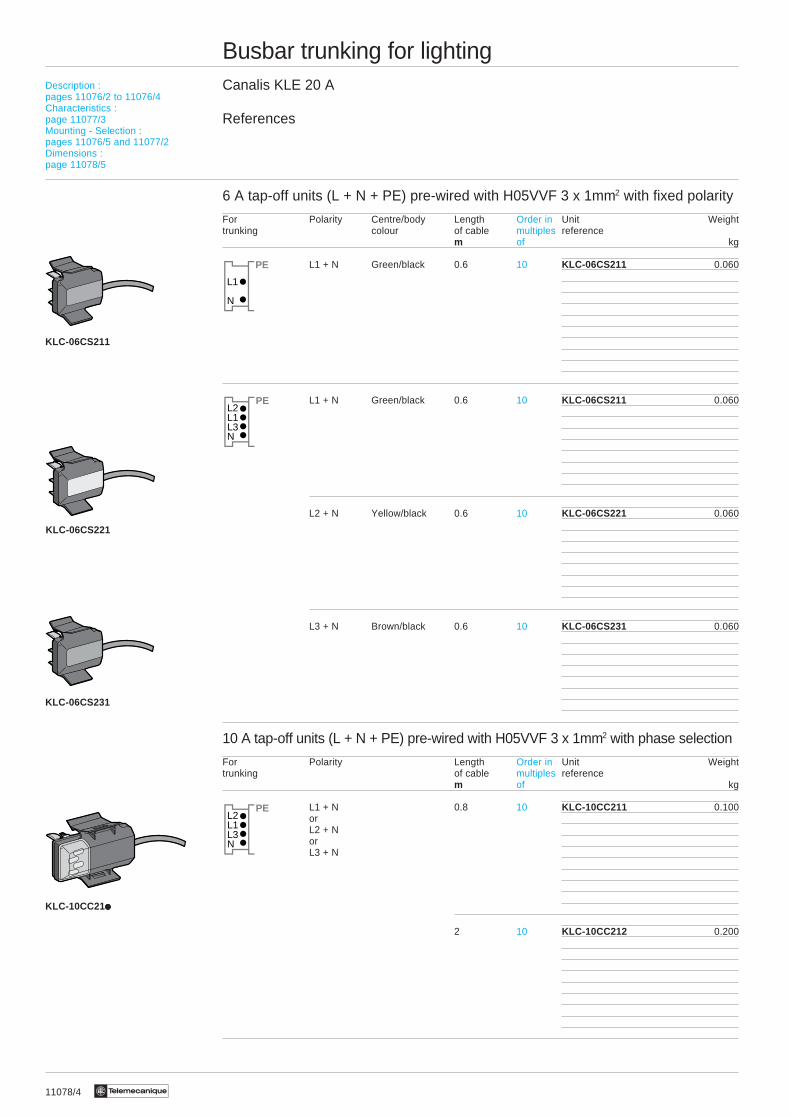
6 A tap-off units (L + N + PE) pre-wired with H05VVF 3 x 1mm2 with fixed polarity
For Polarity Centre/body Length Order in Unit Weighttrunking colour of cable multiples reference
m of kg
L1 + N Green/black 0.6 10 KLC-06CS211 0.060
L1 + N Green/black 0.6 10 KLC-06CS211 0.060
L2 + N Yellow/black 0.6 10 KLC-06CS221 0.060
L3 + N Brown/black 0.6 10 KLC-06CS231 0.060
10 A tap-off units (L + N + PE) pre-wired with H05VVF 3 x 1mm2 with phase selection
For Polarity Length Order in Unit Weighttrunking of cable multiples reference
m of kg
L1 + N 0.8 10 KLC-10CC211 0.100orL2 + NorL3 + N
2 10 KLC-10CC212 0.200
KLC-06CS211
KLC-06CS221
KLC-06CS231
KLC-10CC21i10i10i10i10i10
Description :pages 11076/2 to 11076/4Characteristics :page 11077/3Mounting - Selection :pages 11076/5 and 11077/2Dimensions :page 11078/5
N
L2L1L3
PE
N
L2L1L3
PE
N
L1
PE
11078/5Te
Busbar trunking for lightingCanalis KLE 20 A
Dimensions
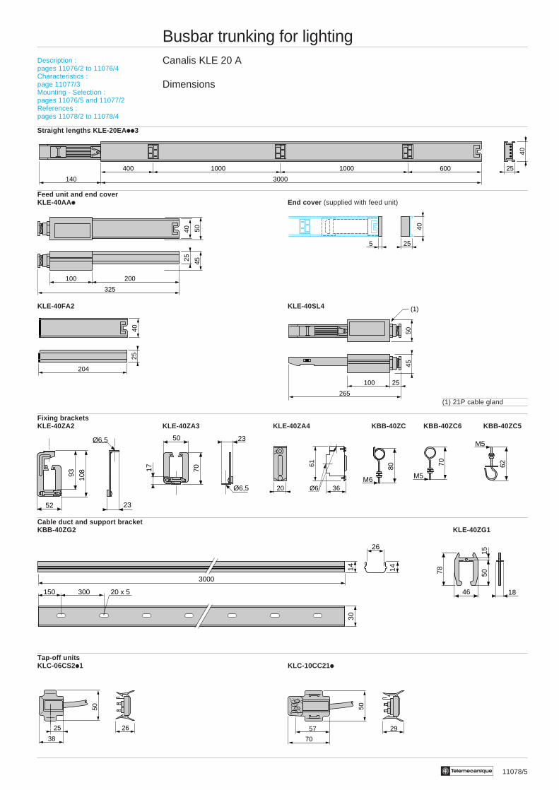
Straight lengths KLE-20EA ii3
Feed unit and end coverKLE-40AA i End cover (supplied with feed unit)
KLE-40FA2 KLE-40SL4
(1) 21P cable gland
Fixing bracketsKLE-40ZA2 KLE-40ZA3 KLE-40ZA4 KBB-40ZC KBB-40ZC6 KBB-40ZC5
Cable duct and support bracketKBB-40ZG2 KLE-40ZG1
Tap-off unitsKLC-06CS2i1 KLC-10CC21i
400 6001000
3000140
1000
40
25
80
M6
70
M5
62
M5
50
38
2625
50
70
57 29
Description :pages 11076/2 to 11076/4Characteristics :page 11077/3Mounting - Selection :pages 11076/5 and 11077/2References :pages 11078/2 to 11078/4
4025 45
50
100 200
325
5
40
25
4025
204
45
25100
265
50
(1)
52
Ø6,5
93
23
108
50 23
7017
Ø6,5
1846
5015
78
26
3000
14 14
300150 20 x 5
30
36
61
20 Ø6

11080/2 Te
Canalis KBA
Canalis KBA
Busbar trunking for lightingCanalis KBA 25 and 40 AFor lighting distribution in small and medium sized buildings, craft and serviceindustries and general commerce
Presentation
2 ratings : 25 and 40 A.2 or 4 live conductors.
Run components1
Receive the KBA busbar trunkingpower supply cable at the end of the run
Feed componentsand end covers
2
2
4
11080/3Te
Fixing devices
Ensure the fixing of the KBA busbar trunkingand suspension of the luminaires.
4Tap-off units
Pre-wired 10 A units.16 A terminal units or for fuses
5
123
!
1
5
11081/2 Te
Busbar trunking for lightingCanalis KBA 25 and 40 A
Description
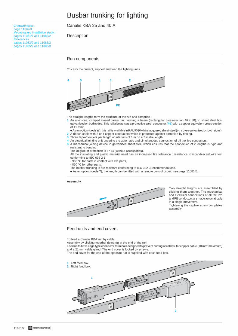
Run components
To carry the current, support and feed the lighting units.
The straight lengths form the structure of the run and comprise :1 An all-in-one, crimped closed carrier rail, forming a beam (rectangular cross-section 46 x 30), in sheet steel hot-
galvanised on both sides. This rail also acts as a protective earth conductor (PE) with a copper equivalent cross-sectionof 11 mm2.i As an option (code W ), this rail is available in RAL 9010 white lacquered sheet steel (on a base galvanised on both sides).
2 A ribbon cable with 2 or 4 copper conductors which is protected against corrosion by tinning.3 Three tap-off outlets per length at intervals of 1 m on a 3 metre length.4 An electrical jointing unit ensuring the automatic and simultaneous connection of all the live conductors.5 A mechanical joining device in galvanised sheet steel which ensures that the connection of 2 lengths is rigid and
resistant to bending.The degree of protection is IP 54 (without accessories).All the insulating and plastic material used has an increased fire tolerance : resistance to incandescent wire testconforming to IEC 695-2-1- 960 °C for parts in contact with live parts,- 850 °C for other parts.The busbar trunking is fire resistant conforming to IEC 332-3 recommendations.i As an option (code T ), the length can be fitted with a remote control circuit, see page 11081/6.
Assembly
Two straight lengths are assembled byclicking them together. The mechanicaland electrical connections of all the liveand PE conductors are made automaticallyin a single movement.Tightening the captive screw completesassembly.
Feed units and end covers
To feed a Canalis KBA run by cable.Assembly by clicking together (jointing) at the end of the run.Feed units have cage type connector terminals designed to prevent cutting of cables, for copper cable (10 mm2 maximum)and a 21 mm cable gland. The end cover is locked by screws.The end cover for the end of the opposite run is supplied with each feed box.
1 Left feed box.2 Right feed box.
Characteristics :page 11082/3Mounting and installation study :pages 11081/7 and 11082/2References :pages 11083/2 and 11083/3pages 11085/2 and 11085/3
4 5 3
PE
21
1
2
11081/3Te
Busbar trunking for lightingCanalis KBA 25 and 40 A
Description
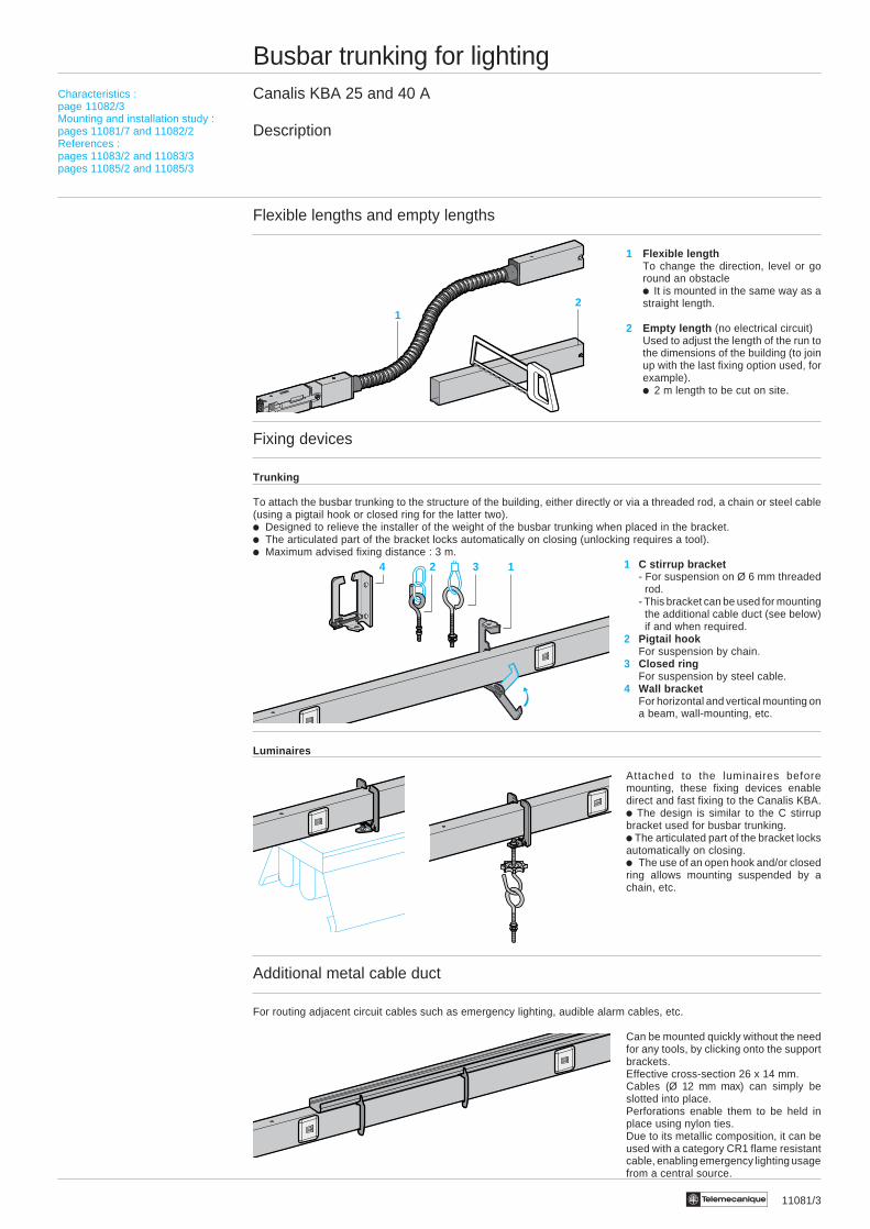
Flexible lengths and empty lengths
1 Flexible lengthTo change the direction, level or goround an obstaclei It is mounted in the same way as astraight length.
2 Empty length (no electrical circuit)Used to adjust the length of the run tothe dimensions of the building (to joinup with the last fixing option used, forexample).i 2 m length to be cut on site.
Fixing devices
Trunking
To attach the busbar trunking to the structure of the building, either directly or via a threaded rod, a chain or steel cable(using a pigtail hook or closed ring for the latter two).i Designed to relieve the installer of the weight of the busbar trunking when placed in the bracket.i The articulated part of the bracket locks automatically on closing (unlocking requires a tool).i Maximum advised fixing distance : 3 m.
1 C stirrup bracket- For suspension on Ø 6 mm threaded
rod.- This bracket can be used for mounting
the additional cable duct (see below)if and when required.
2 Pigtail hookFor suspension by chain.
3 Closed ringFor suspension by steel cable.
4 Wall bracketFor horizontal and vertical mounting ona beam, wall-mounting, etc.
Luminaires
Attached to the luminaires beforemounting, these fixing devices enabledirect and fast fixing to the Canalis KBA.i The design is similar to the C stirrupbracket used for busbar trunking.i The articulated part of the bracket locksautomatically on closing.i The use of an open hook and/or closedring allows mounting suspended by achain, etc.
Additional metal cable duct
For routing adjacent circuit cables such as emergency lighting, audible alarm cables, etc.
Can be mounted quickly without the needfor any tools, by clicking onto the supportbrackets.Effective cross-section 26 x 14 mm.Cables (Ø 12 mm max) can simply beslotted into place.Perforations enable them to be held inplace using nylon ties.Due to its metallic composition, it can beused with a category CR1 flame resistantcable, enabling emergency lighting usagefrom a central source.
2 3 14
12
Characteristics :page 11082/3Mounting and installation study :pages 11081/7 and 11082/2References :pages 11083/2 and 11083/3pages 11085/2 and 11085/3

11081/4 Te
Busbar trunking for lightingCanalis KBA 25 and 40 A
Description
Tap-off units - General
For instant connection of lighting equipment to the CanalisKBA run.i They can be handled when powered up and under load.i The live conductor contacts are a clip type.i The PE connection is established before the phase or
neutral connection.i Installation is facilitated by guides.i A coloured lock holds them in the tap-off outlet.i The body and insulation parts are polyamide with an
increased fire tolerance : resistant to incandescent wiretests ≥ 850 °C (IEC 695-2-1).
KBC-10CSiii 10 A pre-wired units
Prewired with H05VV-F 3 x 1.5 mm2 cable, length 0.8 m or 2 m, pre-stripped at the luminaire end.
i 10 A rating.i 2-pole L + N + PE or 2L + PE with fixed polarity.i The various models enable balanced 3-phase distribution.The connection polarity can be identified from a distance bythe colours on the lock and the casing.
1 Live conductor contacts2 Protective conductor contact3 Lock
KBC-16iiii 16 A terminal units, with phase selection
For connection of luminaires by cable of a specific type, cross-section or length.
i 16 A rating.i Phase selection system by clip-on phase unit, which
enables balanced 3-phase distribution.i 2-pole : L + N + PE (1 mobile unit, fixed neutral) or
2L + PE (2 mobile units).i Displays selection in transparent window.i Access to terminals and fuses is only possible if the tap-
off unit is disconnected (power off).i Supplied with cable bushing.
1 Live conductor contacts2 Protective conductor contact3 Terminals for 0.75 to 2.5 mm2 cable4 Internal cable clamp
KBC-16CB i ii ii ii ii i terminal units, direct (no protection)
For the direct connection (no protection) of luminaires byspecific cable.
KBC-16CFi ii ii ii ii i fused units
For individual protection of each luminaire and ensuringselectivity on a fault.
5 Sub-base for fuse on the phase(1 or 2 sub-bases depending on model).
i For cylindrical fuse NF 8.5 X 31.5 (not supplied),16 A gG max., 20 kA breaking capacity.
123
!
2 1
Characteristics :page 11082/3Mounting and installation study :pages 11081/7 and 11082/2References :pages 11083/2 and 11083/3pages 11085/2 and 11085/3
3
L1 ⇔ L2 ⇔ L3
2
34
1
5
11081/5Te
Busbar trunking for lightingCanalis KBA 25 and 40 A
Description
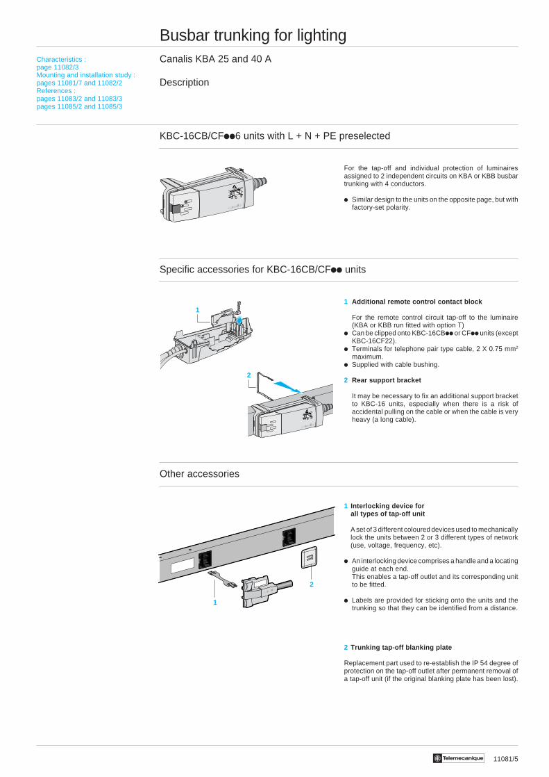
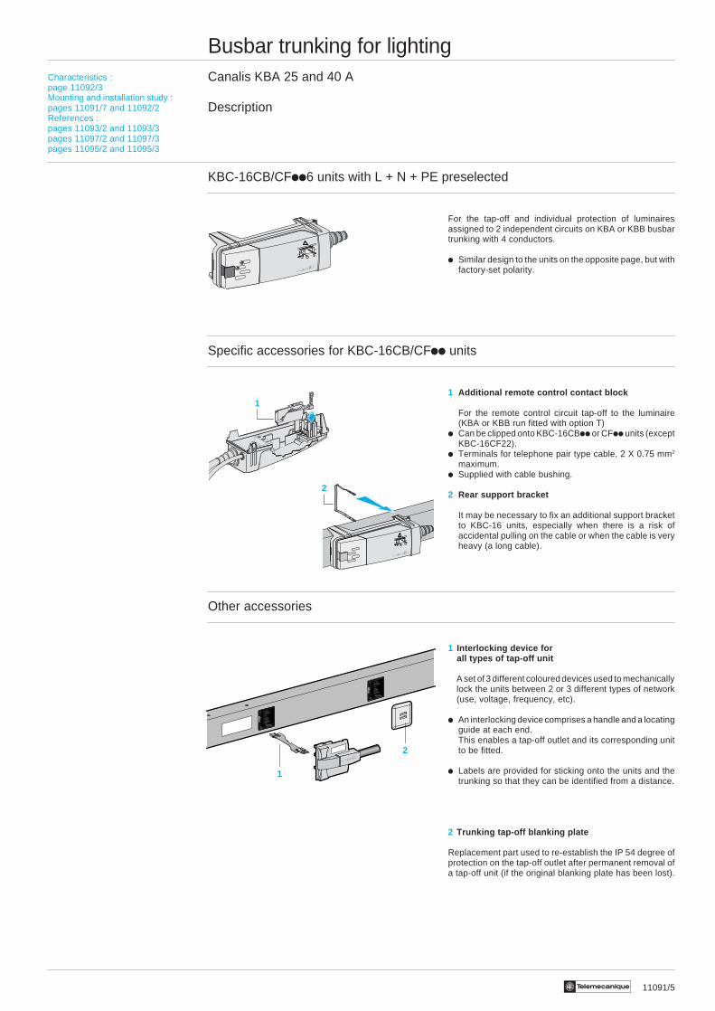
KBC-16CB/CFii6 units with L + N + PE preselected
For the tap-off and individual protection of luminairesassigned to 2 independent circuits on KBA or KBB busbartrunking with 4 conductors.
i Similar design to the units on the opposite page, but withfactory-set polarity.
Specific accessories for KBC-16CB/CFii units
1 Additional remote control contact block
For the remote control circuit tap-off to the luminaire(KBA or KBB run fitted with option T)
i Can be clipped onto KBC-16CBii or CFii units (exceptKBC-16CF22).
i Terminals for telephone pair type cable, 2 X 0.75 mm2
maximum.i Supplied with cable bushing.
2 Rear support bracket
It may be necessary to fix an additional support bracketto KBC-16 units, especially when there is a risk ofaccidental pulling on the cable or when the cable is veryheavy (a long cable).
Other accessories
1 Interlocking device forall types of tap-off unit
A set of 3 different coloured devices used to mechanicallylock the units between 2 or 3 different types of network(use, voltage, frequency, etc).
i An interlocking device comprises a handle and a locatingguide at each end.This enables a tap-off outlet and its corresponding unitto be fitted.
i Labels are provided for sticking onto the units and thetrunking so that they can be identified from a distance.
2 Trunking tap-off blanking plate
Replacement part used to re-establish the IP 54 degree ofprotection on the tap-off outlet after permanent removal ofa tap-off unit (if the original blanking plate has been lost).
123
!
1
Characteristics :page 11082/3Mounting and installation study :pages 11081/7 and 11082/2References :pages 11083/2 and 11083/3pages 11085/2 and 11085/3
123
!
2
1
2
11081/6 Te
Busbar trunking for lightingCanalis KBA 25 and 40 A
Description
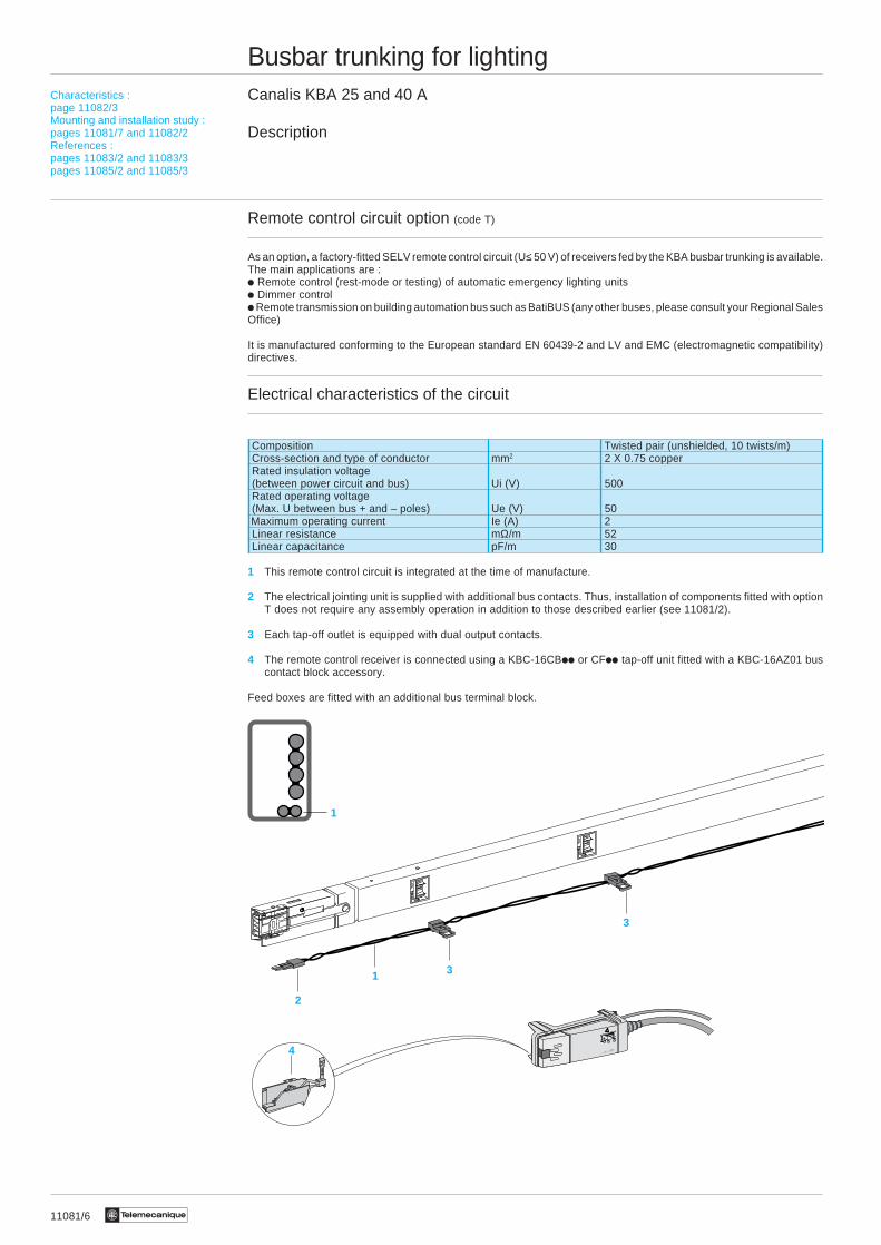
Remote control circuit option (code T)
As an option, a factory-fitted SELV remote control circuit (U≤ 50 V) of receivers fed by the KBA busbar trunking is available.The main applications are :i Remote control (rest-mode or testing) of automatic emergency lighting unitsi Dimmer controli Remote transmission on building automation bus such as BatiBUS (any other buses, please consult your Regional SalesOffice)
It is manufactured conforming to the European standard EN 60439-2 and LV and EMC (electromagnetic compatibility)directives.
Electrical characteristics of the circuit
Composition Twisted pair (unshielded, 10 twists/m)Cross-section and type of conductor mm2 2 X 0.75 copperRated insulation voltage(between power circuit and bus) Ui (V) 500Rated operating voltage(Max. U between bus + and – poles) Ue (V) 50
Maximum operating current Ie (A) 2Linear resistance mΩ/m 52Linear capacitance pF/m 30
1 This remote control circuit is integrated at the time of manufacture.
2 The electrical jointing unit is supplied with additional bus contacts. Thus, installation of components fitted with optionT does not require any assembly operation in addition to those described earlier (see 11081/2).
3 Each tap-off outlet is equipped with dual output contacts.
4 The remote control receiver is connected using a KBC-16CBii or CFii tap-off unit fitted with a KBC-16AZ01 buscontact block accessory.
Feed boxes are fitted with an additional bus terminal block.
1
2
1 3
3
4
Characteristics :page 11082/3Mounting and installation study :pages 11081/7 and 11082/2References :pages 11083/2 and 11083/3pages 11085/2 and 11085/3

11081/7Te
1
3
2
5
44
Click !
Busbar trunking for lightingCanalis KBA 25 and 40 A
Mounting
Mounting instructions detailing the various stages of assembly are included with the trunking.However, the main operations outlined below illustrate how easily and quickly it can be put together.
Assembling the straight lengths and feed units
Installing the busbar trunking
Installing and connecting the luminaires
The luminaires are fitted with suspension brackets and tap-off unit before mounting.
Choix :page 11003/2Caractéristiques :page 11003/3Références :pages 11004/3 et 11005/2Encombrements :page 11005/3
Description :pages 11081/2 to 11081/6Characteristics :page 11082/3References :pages 11083/2 and 11083/3pages 11085/2 and 11085/3
Fixed polaritytap-off unit
Phase selectiontap-off unit
1Click !
2
Click !
1
2
3
Canalis KBB
Canalis KBA
Click !2
1

11082/2 Te
Busbar trunking for lightingCanalis KBA 25 and 40 A
Installation study
Selecting the busbar trunking
Knowing :i The type of luminaire (types of lamp, power, compen-sated or not), their weight, number and distributioni The structure of the premises (option of mountingbusbar trunking)i External influences (IP degree required)
Reminder of the various stages of selecting the busbar trunking (See the selection and study guides on pages0120Q/3 and 11068/2 to 11068/11).
i Select the type of busbar trunking depending on the possible fixing distance and/or the weight of the luminaires.i Select the number of live conductors depending on the distribution scheme chosen or the number of lighting circuits.i Select the Inc rating depending on the operating current.i Select the power supply cable (type and cross-section) depending on the operating current and the type of protectionagainst overloads.i Check the voltage drops .i Select the type of protection against short-circuits and its coordination with the busbar trunking.
Option T : remote control circuit
This U < 50 V (SELV) circuit is used for the remote control of equipment fed by KBA busbar trunking.Its main uses include control of automatic emergency lighting units and remote dimmer control.
Option W : white lacquer finish (RAL 9010)
For installation in locations where aesthetic design is of particular importance (retail outlet, exhibition halls, etc).
Feed boxes
The terms “left” and “right” are given in relation to the busbar trunking reference side (end fitted with tap-off outlets).When the run is installed, a minimum gap of 200 mm must be left at each end so that the feed box can be removed ifnecessary.
Flexible lengths
These are used to change direction (nominal length = 500 mm) and level or to go round obstacles* (nominal length = 2 m).* This configuration can also be achieved using 2 feed boxes (KBA-40SL4 + KBA-40AA4) and an appropriately sizedflexible cable.
Installing and fixing the busbar trunking
The normal position for mounting is edgewise.The fixing distance depends on the weight of the luminaires suspended between 2 mountings and must not exceed 3 m *.* This fixing distance can be increased to 4 m if the busbar trunking does not have any luminaires (equipment fixed to thestructure of the building) or if the luminaires are suspended on the straight part of a trunking mounting.
Selecting the tap-off units
Tap-off units are always single-phase L + N + PE or 2L + PE.Their selection depends on the functions required during installation and operation.
Selection criteria Fixed polarity Polarity with phase selectionPre-wired (H05VVF 1.5 mm2) With terminals FusedKBC-10CS KBC-16CB KBC-16CF
Simplicity/cost tEquipment suspended below the trunking tEquipment fixed to the framework (exc. trunking) t tOpen-ended installation (modification of scheme) t tSpecific cable (type, cross-section, length, etc) t tIndividual protection of the luminaire and cable tSelectivity of protection on a fault tRemote controlled equipment (option T) t t
Additional cable duct
The cable duct is designed mainly to receive the emergency lighting circuit cables which :- feed the equipment from a central source,- feed and/or control autonomous equipment (automatic emergency lighting units)It can also receive additional circuit cables such as telephone, audible alarm cables, etc.Distance between supports : 3 x 3 m supports are required.
Description :pages 11081/2 to 11081/6Characteristics :page 11082/3References :pages 11083/2 and 11083/3pages 11085/2 and 11085/3
11082/3Te
Busbar trunking for lightingCanalis KBA 25 and 40 A
Characteristics
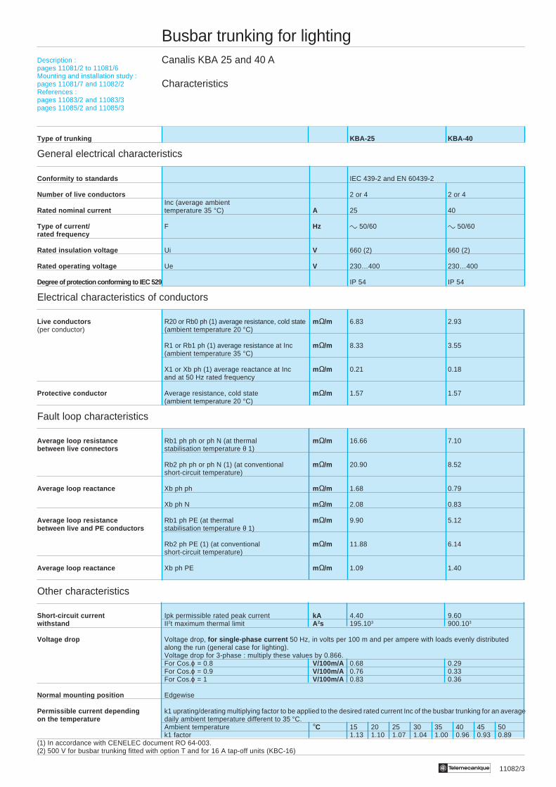
Type of trunking KBA-25 KBA-40
General electrical characteristics
Conformity to standards IEC 439-2 and EN 60439-2
Number of live conductors 2 or 4 2 or 4Inc (average ambient
Rated nominal current temperature 35 °C) A 25 40
Type of current/ F Hz c 50/60 c 50/60rated frequency
Rated insulation voltage Ui V 660 (2) 660 (2)
Rated operating voltage Ue V 230…400 230…400
Degree of protection conforming to IEC 529 IP 54 IP 54
Electrical characteristics of conductors
Live conductors R20 or Rb0 ph (1) average resistance, cold state mΩ/m 6.83 2.93(per conductor) (ambient temperature 20 °C)
R1 or Rb1 ph (1) average resistance at Inc mΩ/m 8.33 3.55(ambient temperature 35 °C)
X1 or Xb ph (1) average reactance at Inc mΩ/m 0.21 0.18and at 50 Hz rated frequency
Protective conductor Average resistance, cold state mΩ/m 1.57 1.57(ambient temperature 20 °C)
Fault loop characteristics
Average loop resistance Rb1 ph ph or ph N (at thermal mΩ/m 16.66 7.10between live connectors stabilisation temperature θ 1)
Rb2 ph ph or ph N (1) (at conventional mΩ/m 20.90 8.52short-circuit temperature)
Average loop reactance Xb ph ph mΩ/m 1.68 0.79
Xb ph N mΩ/m 2.08 0.83
Average loop resistance Rb1 ph PE (at thermal mΩ/m 9.90 5.12between live and PE conductors stabilisation temperature θ 1)
Rb2 ph PE (1) (at conventional mΩ/m 11.88 6.14short-circuit temperature)
Average loop reactance Xb ph PE mΩ/m 1.09 1.40
Other characteristics
Short-circuit current Ipk permissible rated peak current kA 4.40 9.60withstand II2t maximum thermal limit A2s 195.103 900.103
Voltage drop Voltage drop, for single-phase current 50 Hz, in volts per 100 m and per ampere with loads evenly distributedalong the run (general case for lighting).Voltage drop for 3-phase : multiply these values by 0.866.For Cos.ϕ = 0.8 V/100m/A 0.68 0.29For Cos.ϕ = 0.9 V/100m/A 0.76 0.33For Cos.ϕ = 1 V/100m/A 0.83 0.36
Normal mounting position Edgewise
Permissible current depending k1 uprating/derating multiplying factor to be applied to the desired rated current Inc of the busbar trunking for an averageon the temperature daily ambient temperature different to 35 °C.
Ambient temperature °C 15 20 25 30 35 40 45 50k1 factor 1.13 1.10 1.07 1.04 1.00 0.96 0.93 0.89
(1) In accordance with CENELEC document RO 64-003.(2) 500 V for busbar trunking fitted with option T and for 16 A tap-off units (KBC-16)
Description :pages 11081/2 to 11081/6Mounting and installation study :pages 11081/7 and 11082/2References :pages 11083/2 and 11083/3pages 11085/2 and 11085/3
11083/2 Te
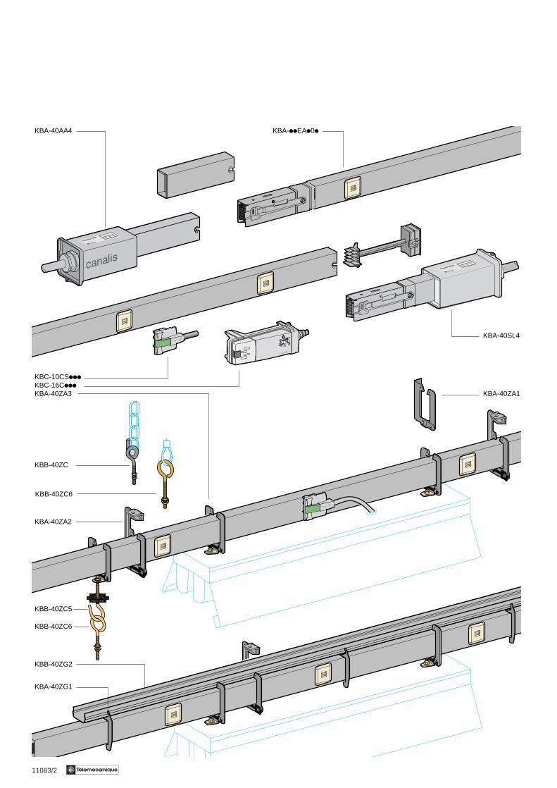
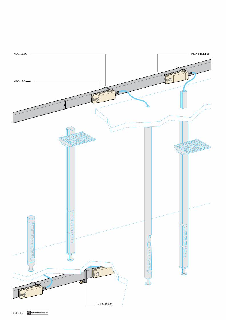
KBA-40AA4 KBA-iiEAi0i
KBA-40SL4
KBC-10CSiiiKBC-16CiiiKBA-40ZA3
KBB-40ZC
KBA-40ZA2
KBB-40ZC5
KBB-40ZC6
KBB-40ZG2
KBA-40ZG1
KBA-40ZA1
KBB-40ZC6
11084/2 Te
KBA-iiELi0i
KBA-40ZA1
KBC-16Ciii
KBC-16ZC

11083/3Te
Busbar trunking for lightingCanalis KBA 25 and 40 ARemote control circuit option (code T)White lacquer steel casing option (code W)
References
Straight lengths
Type of Length No. of Order in 25 A rating Weight 40 A rating Weight Option (1)trunking tap- multiples Unit Unit
m offs of reference kg reference kg T W
3 3 6 KBA-25EA203 2.400 KBA-40EA203 2.700 t t
2 3 6 KBA-40EL202 1.700 KBA-40EL202 1.700 t –
3 3 6 KBA-25EA403 2.600 KBA-40EA403 3.100 t t
2 3 6 KBA-40EL402 1.900 KBA-40EL402 1.900 t t
Other lengths common to the 2 ratings (In = 40 A) and 2 polarities (3L + N + PE)
Feed units + end covers
Description Mounting Device connected by cable Reference Weight Option (1)Terminals Entry Max Ø kg T W
Feed unit Left 10 mm2 CG 21 19 mm KBA-40AA4 0.400 t t
Right 10 mm2 CG 21 19 mm KBA-40SL4 0.500 t t
Other lengths
Description Use Length Order in Reference Weight Option (1)multiples
m of kg T W
Flexible length Elbow, changing level, 0.5 – KBA-40EF400 0.800 t tgoing round obstacles
2 – KBA-40EF402 1.900 t t
Empty length Adjusting the length at the 2 6 KBA-40EV002 1.600 – tend of the run (to be cut)
Fixing devices and accessories
For fixing Description For mounting Maximum Order in Unit Weight Option (1)load multiples referencekg of kg T W
Trunking C stirrup Suspended on 60 10 KBA-40ZA2 0.070 – tbracket threaded rod
Pigtail Suspended on 60 10 KBB-40ZC 0.020 – –hook chain or steel cable
(used with KBA-40ZA2)
U bracket Wall, 60 10 KBA-40ZA1 0.070 – tsurface mounting
Luminaires Suspension Directly under 45 10 KBA-40ZA3 0.050 – tbracket busbar trunking
Open Suspended (chain) 45 10 KBB-40ZC5 0.050 – –hook (used with KBA-40ZA3)
Ring On luminaire 45 10 KBB-40ZC6 0.050 – –
Additional cable ductDescription Use Order in Unit Weight Option (1)
multiples referenceof kg T W
Metal cable duct Routing adjacent circuits 6 KBB-40ZG2 0.800 – t
Support bracket 3 x 3 m brackets are required 10 KBA-40ZG1 0.030 – t
(1) t Options (can be ordered together). Add T and/or W to the reference. For example : KBA-25EA403TW
NL3L1L2PE
N
L1PE
Description :pages 11081/2 to 11081/6Characteristics :page 11082/3Mounting and installation study :pages 11081/7 and 11082/2Dimensions :pages 11086/2 and 11086/3
11085/2 Te
Busbar trunking for lightingCanalis KBA 25 and 40 ATap-off units
References
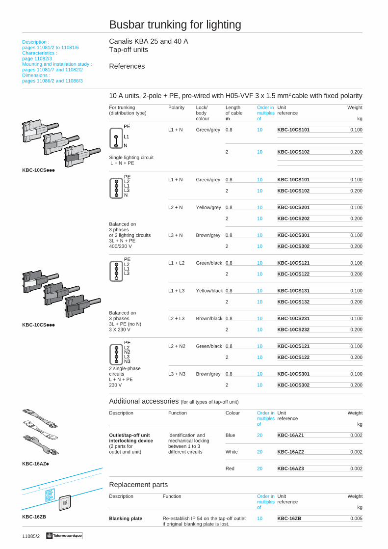
10 A units, 2-pole + PE, pre-wired with H05-VVF 3 x 1.5 mm2 cable with fixed polarity
For trunking Polarity Lock/ Length Order in Unit Weight(distribution type) body of cable multiples reference
colour m of kg
L1 + N Green/grey 0.8 10 KBC-10CS101 0.100
2 10 KBC-10CS102 0.200Single lighting circuit L + N + PE
L1 + N Green/grey 0.8 10 KBC-10CS101 0.100
2 10 KBC-10CS102 0.200
L2 + N Yellow/grey 0.8 10 KBC-10CS201 0.100
2 10 KBC-10CS202 0.200Balanced on3 phasesor 3 lighting circuits L3 + N Brown/grey 0.8 10 KBC-10CS301 0.1003L + N + PE400/230 V 2 10 KBC-10CS302 0.200
L1 + L2 Green/black 0.8 10 KBC-10CS121 0.100
2 10 KBC-10CS122 0.200
L1 + L3 Yellow/black 0.8 10 KBC-10CS131 0.100
2 10 KBC-10CS132 0.200
Balanced on3 phases L2 + L3 Brown/black 0.8 10 KBC-10CS231 0.1003L + PE (no N)3 X 230 V 2 10 KBC-10CS232 0.200
L2 + N2 Green/black 0.8 10 KBC-10CS121 0.100
2 10 KBC-10CS122 0.200
2 single-phasecircuits L3 + N3 Brown/grey 0.8 10 KBC-10CS301 0.100L + N + PE230 V 2 10 KBC-10CS302 0.200
Additional accessories (for all types of tap-off unit)
Description Function Colour Order in Unit Weightmultiples referenceof kg
Outlet/tap-off unit Identification and Blue 20 KBC-16AZ1 0.002interlocking device mechanical locking(2 parts for between 1 to 3outlet and unit) different circuits White 20 KBC-16AZ2 0.002
Red 20 KBC-16AZ3 0.002
Replacement parts
Description Function Order in Unit Weightmultiples referenceof kg
Blanking plate Re-establish IP 54 on the tap-off outlet 10 KBC-16ZB 0.005if original blanking plate is lost.
Description :pages 11081/2 to 11081/6Characteristics :page 11082/3Mounting and installation study :pages 11081/7 and 11082/2Dimensions :pages 11086/2 and 11086/3
N
L1
PE
NL3L1L2PE
L3N3
N2L2PE
KBC-16AZi
KBC-10CSiii
KBC-10CSiii
KBC-16ZB
L3L1L2PE
11085/3Te
Busbar trunking for lightingCanalis KBA 25 and 40 ATap-off units
References
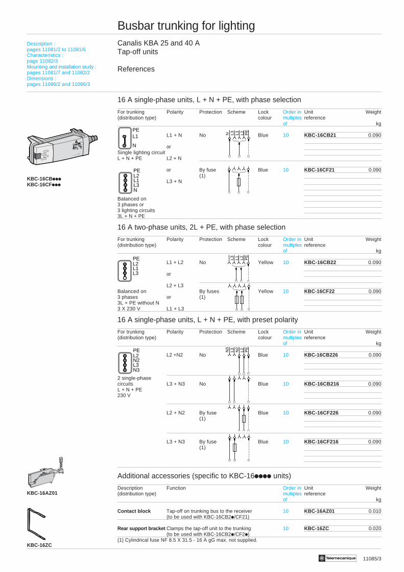
16 A single-phase units, L + N + PE, with phase selection
For trunking Polarity Protection Scheme Lock Order in Unit Weight(distribution type) colour multiples reference
of kg
L1 + N No Blue 10 KBC-16CB21 0.090
orSingle lighting circuitL + N + PE L2 + N
or By fuse Blue 10 KBC-16CF21 0.090(1)
L3 + N
Balanced on3 phases or3 lighting circuits3L + N + PE
16 A two-phase units, 2L + PE, with phase selection
For trunking Polarity Protection Scheme Lock Order in Unit Weight(distribution type) colour multiples reference
of kg
L1 + L2 No Yellow 10 KBC-16CB22 0.090
or
L2 + L3Balanced on By fuses Yellow 10 KBC-16CF22 0.0903 phases or (1)3L + PE without N3 X 230 V L1 + L3
16 A single-phase units, L + N + PE, with preset polarity
For trunking Polarity Protection Scheme Lock Order in Unit Weight(distribution type) colour multiples reference
of kg
L2 +N2 No Blue 10 KBC-16CB226 0.090
2 single-phasecircuits L3 + N3 No Blue 10 KBC-16CB216 0.090L + N + PE230 V
L2 + N2 By fuse Blue 10 KBC-16CF226 0.090(1)
L3 + N3 By fuse Blue 10 KBC-16CF216 0.090(1)
Additional accessories (specific to KBC-16iiii units)
Description Function Order in Unit Weight(distribution type) multiples reference
of kg
Contact block Tap-off on trunking bus to the receiver 10 KBC-16AZ01 0.010(to be used with KBC-16CB2i/CF21)
Rear support bracket Clamps the tap-off unit to the trunking 10 KBC-16ZC 0.020(to be used with KBC-16CB2i/CF2i)
(1) Cylindrical fuse NF 8.5 X 31.5 - 16 A gG max. not supplied.
N L3 L1 L2 PE
KBC-16CBiiiKBC-16CFiii
KBC-16AZ01
N
L1PE
NL3L1L2PE
L3N3
N2L2PE
123
!
KBC-16ZC
L3L1L2PE L3 L1 L2 P
E
N3
L3 N2
L2 PE
Description :pages 11081/2 to 11081/6Characteristics :page 11082/3Mounting and installation study :pages 11081/7 and 11082/2Dimensions :pages 11086/2 and 11086/3
11086/2 Te
Busbar trunking for lightingCanalis KBA 25 and 40 A
Dimensions
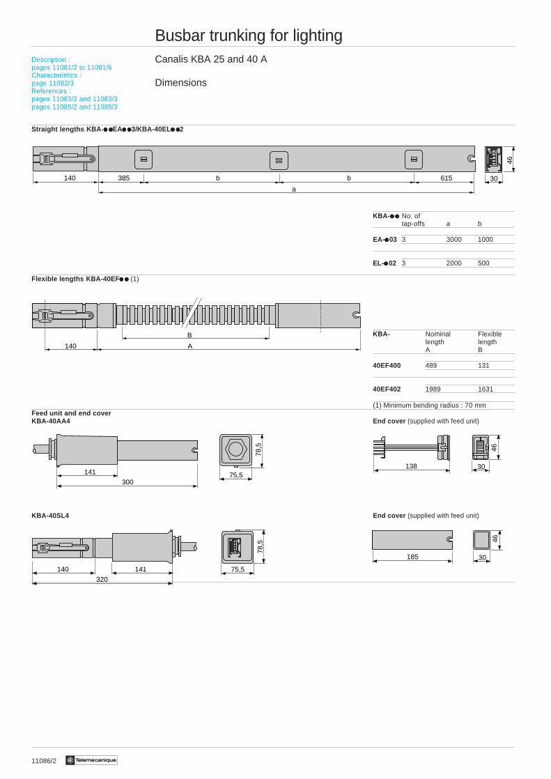
Straight lengths KBA- i ii ii ii ii iEAi ii ii ii ii i3/KBA-40EL i ii ii ii ii i2
KBA- i ii ii ii ii i No. oftap-offs a b
EA-iiiii03 3 3000 1000
EL-iiiii02 3 2000 500
Flexible lengths KBA-40EF i ii ii ii ii i (1)
KBA- Nominal Flexiblelength lengthA B
40EF400 489 131
40EF402 1989 1631
(1) Minimum bending radius : 70 mmFeed unit and end coverKBA-40AA4 End cover (supplied with feed unit)
KBA-40SL4 End cover (supplied with feed unit)
30140 b385
a
b 615
46
A140
B
30138
46
30185
46
30075,5141
78,5
320
75,5141
78,5
140
Description :pages 11081/2 to 11081/6Characteristics :page 11082/3References :pages 11083/2 and 11083/3pages 11085/2 and 11085/3
11086/3Te
Busbar trunking for lightingCanalis KBA 25 and 40 A
Dimensions
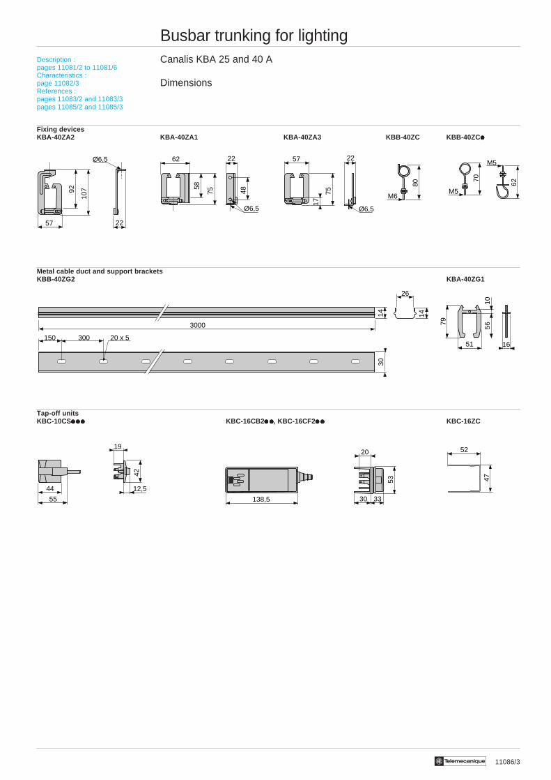
Fixing devicesKBA-40ZA2 KBA-40ZA1 KBA-40ZA3 KBB-40ZC KBB-40ZC iiiii
Metal cable duct and support bracketsKBB-40ZG2 KBA-40ZG1
Tap-off unitsKBC-10CSiiiiiiiiiiiiiii KBC-16CB2 i ii ii ii ii i, KBC-16CF2i ii ii ii ii i KBC-16ZC
70
M5
62
M5
52
47
80
M6
57
Ø6,5
92
107
22
62 22
58
75 48
Ø6,5
57 22
17
75
Ø6,5
26
3000
14 14
300150 20 x 5
30
12,5
19
44
55
42
3330
20
138,5
53
Description :pages 11081/2 to 11081/6Characteristics :page 11082/3References :pages 11083/2 and 11083/3pages 11085/2 and 11085/3
1651
5610
79

11090/2 Te
Busbar trunking for lightingCanalis KBB 25 and 40 AFor lighting distribution in large industrial and commercial buildings with heavyand/or numerous luminaires
Presentation
2 ratings : 25 and 40 A.1 or 2 circuits with 2 or 4 live conductors
Run components1
Receive the KBB busbar trunkingpower supply cable at the end of the run
2
4
Feed componentsand end covers
2
11090/3Te
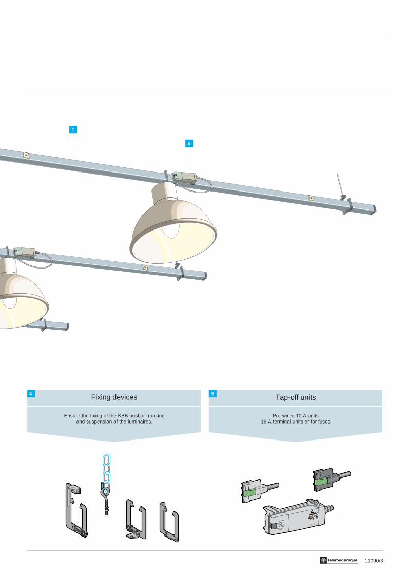
Fixing devices
Ensure the fixing of the KBB busbar trunkingand suspension of the luminaires.
4Tap-off units
Pre-wired 10 A units16 A terminal units or for fuses
5
1
5
123
!

11091/2 Te
Busbar trunking for lightingCanalis KBB 25 and 40 A
Description
Run components
To carry the current, support and feed thelighting units.Due to its robustness, the KBB is particu-larly suitable for installations with largefixing distances and/or heavy or numer-ous luminaires.
The straight lengths form the structure of the run and comprise :1 An all-in-one, high rigidity, crimped closed carrier rail, forming a beam (rectangular cross-section 46 x 46), in sheet
steel hot-galvanised on both sides.This rail also acts as a protective earth conductor (PE) with a copper equivalent cross-section of 22 mm2.i As an option (code W ), this rail is available in RAL 9010 white lacquered sheet steel (on a base galvanised on both sides).
2 1 or 2 ribbon cables with 2 or 4 copper conductors protected against corrosion by tinning and comprising 1 or 2independent circuits.
3 Three tap-off outlets per length at intervals of 1 m on the main circuit (front side), 2 outlets on the adjacent circuit (rearside).
4 An electrical jointing unit ensuring the automatic and simultaneous connection of all the live conductors.5 A mechanical joining device in 2 parts made of pressed sheet steel which ensures that the connection of 2 lengths is
rigid and resistant to bending.The degree of protection is IP 54 (without accessories).All the insulating and plastic material used has an increased fire tolerance : resistance to incandescent wire testconforming to IEC 695-2-1- 960 °C for parts in contact with live parts,- 850 °C for other parts.The busbar trunking is fire resistant conforming to IEC 332-3 recommendations.i As an option (code T ), the length can be fitted with a remote control circuit, see page : 11091/4.
Assembly
Two straight lengths are assembled byclicking them together to provide theelectrical connection and by replacing thelower part of the mechanical joint to providethe mechanical connection.
Feed units and end covers
To feed a Canalis KBB run by cable.Assembly by clicking together (jointing) at the end of the run.Feed units have cage type connector terminals designed to prevent cutting of cables, for copper cable (10 mm2 maximum)and a 21 mm cable gland. The end cover is locked by screws.The end cover for the end of the opposite run is supplied with each feed box.
1 Feed box with 1 circuit. 2 Feed box with 2 circuits.
1 2
1
Characteristics :page 11092/3Mounting and installation study :pages 11091/7 and 11092/2References :pages 11093/2 and 11093/3pages 11097/2 and 11097/3pages 11095/2 and 11095/3
4 5 3 2
PE
1
Canalis® KBB

11091/4 Te
Busbar trunking for lightingCanalis KBB 25 and 40 A
Description
Tap-off units - General
For instant connection of lighting equipment to the CanalisKBB run.i They can be handled when powered up and under load.i The live conductor contacts are a clip type.i The PE connection is established before the phase or
neutral connection.i Installation is facilitated by guides.i A coloured lock holds them in the tap-off outlet.i The body and insulation parts are polyamide with an
increased fire tolerance : resistant to incandescent wiretests ≥ 850 °C (IEC 695-2-1).
KBC-10CSiii 10 A pre-wired units
Prewired with H05VV-F 3 x 1.5 mm2 cable, length 0.8 m or 2 m, pre-stripped at the luminaire end.
i 10 A rating.i 2-pole L + N + PE or 2L + PE with fixed polarity.i The various models enable balanced 3-phase distribution.The connection polarity can be identified from a distance bythe colours on the lock and the casing.
1 Live conductor contacts2 Protective conductor contact3 Lock
KBC-16iiii 16 A terminal units,with phase selection
For connection of luminaires by cable of a specific type, cross-section or length.
i 16 A rating.i Phase selection system by clip-on phase unit, which
enables balanced 3-phase distribution.i 2-pole : L + N + PE (1 mobile unit, fixed neutral) or
2L + PE (2 mobile units).i Displays selection in transparent window.i Access to terminals and fuses is only possible if the tap-
off unit is disconnected (power off).i Supplied with cable bushing.
1 Live conductor contacts2 Protective conductor contact3 Terminals for 0.75 to 2.5 mm2 cable4 Internal cable clamp
KBC-16CB i ii ii ii ii i terminal units, direct (no protection)
For the direct connection (no protection) of luminaires byspecific cable.
KBC-16CFi ii ii ii ii i fused units
For individual protection of each luminaire and ensuringselectivity on a fault.
5 Sub-base for fuse on the length(1 or 2 sub-bases depending on model).
i For cylindrical fuse NF 8.5 X 31.5 (not supplied),16 A gG max., 20 kA breaking capacity.
123
!
2 13
L1 ⇔ L2 ⇔ L3
2
34
1
5
Characteristics :page 11092/3Mounting and installation study :pages 11091/7 and 11092/2References :pages 11093/2 and 11093/3pages 11097/2 and 11097/3pages 11095/2 and 11095/3
11091/5Te
Busbar trunking for lightingCanalis KBA 25 and 40 A
Description
KBC-16CB/CFii6 units with L + N + PE preselected
For the tap-off and individual protection of luminairesassigned to 2 independent circuits on KBA or KBB busbartrunking with 4 conductors.
i Similar design to the units on the opposite page, but withfactory-set polarity.
Specific accessories for KBC-16CB/CFii units
1 Additional remote control contact block
For the remote control circuit tap-off to the luminaire(KBA or KBB run fitted with option T)
i Can be clipped onto KBC-16CBii or CFii units (exceptKBC-16CF22).
i Terminals for telephone pair type cable, 2 X 0.75 mm2
maximum.i Supplied with cable bushing.
2 Rear support bracket
It may be necessary to fix an additional support bracketto KBC-16 units, especially when there is a risk ofaccidental pulling on the cable or when the cable is veryheavy (a long cable).
Other accessories
1 Interlocking device forall types of tap-off unit
A set of 3 different coloured devices used to mechanicallylock the units between 2 or 3 different types of network(use, voltage, frequency, etc).
i An interlocking device comprises a handle and a locatingguide at each end.This enables a tap-off outlet and its corresponding unitto be fitted.
i Labels are provided for sticking onto the units and thetrunking so that they can be identified from a distance.
2 Trunking tap-off blanking plate
Replacement part used to re-establish the IP 54 degree ofprotection on the tap-off outlet after permanent removal ofa tap-off unit (if the original blanking plate has been lost).
123
!
1
123
!
2
1
2
Characteristics :page 11092/3Mounting and installation study :pages 11091/7 and 11092/2References :pages 11093/2 and 11093/3pages 11097/2 and 11097/3pages 11095/2 and 11095/3
11091/6 Te
Busbar trunking for lightingCanalis KBB 25 and 40 A
Description
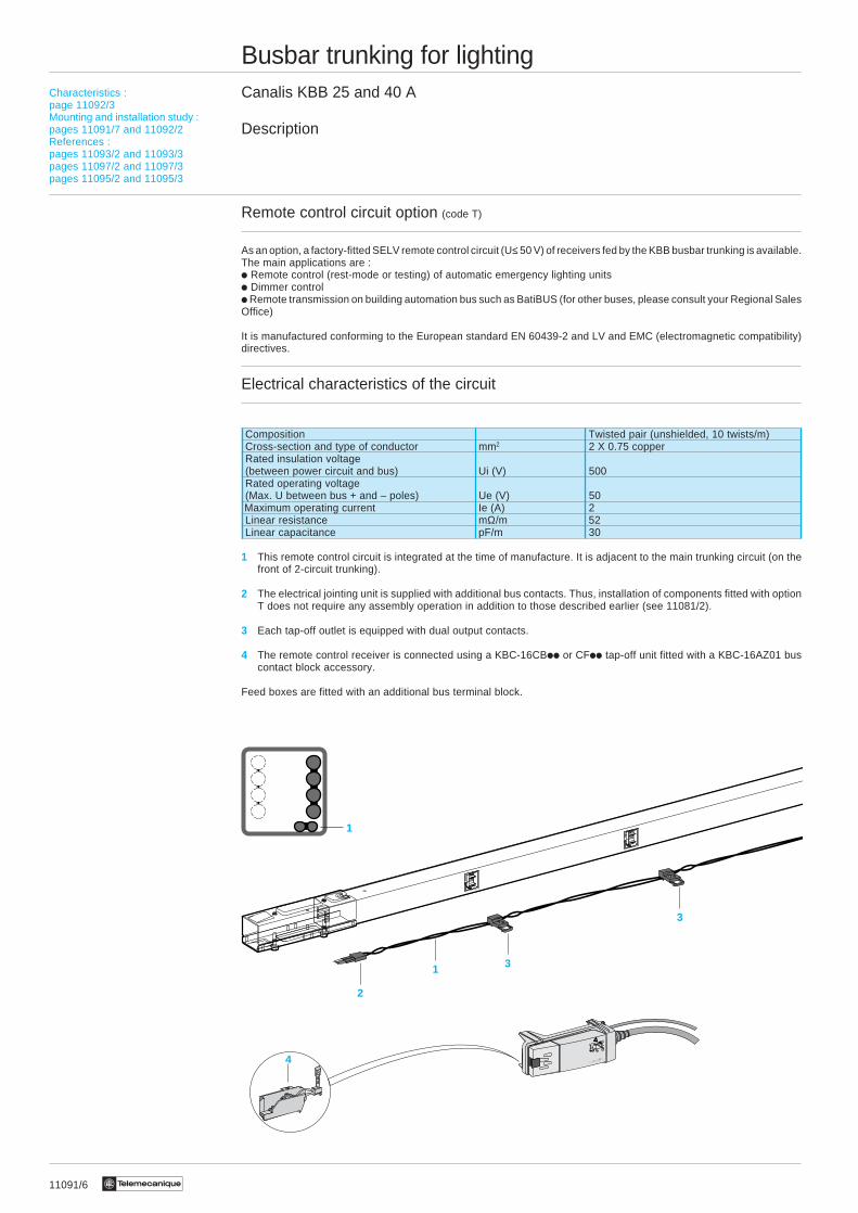
Remote control circuit option (code T)
As an option, a factory-fitted SELV remote control circuit (U≤ 50 V) of receivers fed by the KBB busbar trunking is available.The main applications are :i Remote control (rest-mode or testing) of automatic emergency lighting unitsi Dimmer controli Remote transmission on building automation bus such as BatiBUS (for other buses, please consult your Regional SalesOffice)
It is manufactured conforming to the European standard EN 60439-2 and LV and EMC (electromagnetic compatibility)directives.
Electrical characteristics of the circuit
Composition Twisted pair (unshielded, 10 twists/m)Cross-section and type of conductor mm2 2 X 0.75 copperRated insulation voltage(between power circuit and bus) Ui (V) 500Rated operating voltage(Max. U between bus + and – poles) Ue (V) 50
Maximum operating current Ie (A) 2Linear resistance mΩ/m 52Linear capacitance pF/m 30
1 This remote control circuit is integrated at the time of manufacture. It is adjacent to the main trunking circuit (on thefront of 2-circuit trunking).
2 The electrical jointing unit is supplied with additional bus contacts. Thus, installation of components fitted with optionT does not require any assembly operation in addition to those described earlier (see 11081/2).
3 Each tap-off outlet is equipped with dual output contacts.
4 The remote control receiver is connected using a KBC-16CBii or CFii tap-off unit fitted with a KBC-16AZ01 buscontact block accessory.
Feed boxes are fitted with an additional bus terminal block.
1
2
1 3
3
4
Characteristics :page 11092/3Mounting and installation study :pages 11091/7 and 11092/2References :pages 11093/2 and 11093/3pages 11097/2 and 11097/3pages 11095/2 and 11095/3

11091/6 Te
Busbar trunking for lightingCanalis KBB 25 and 40 A
Description
Remote control circuit option (code T)
As an option, a factory-fitted SELV remote control circuit (U≤ 50 V) of receivers fed by the KBB busbar trunking is available.The main applications are :i Remote control (rest-mode or testing) of automatic emergency lighting unitsi Dimmer controli Remote transmission on building automation bus such as BatiBUS (for other buses, please consult your Regional SalesOffice)
It is manufactured conforming to the European standard EN 60439-2 and LV and EMC (electromagnetic compatibility)directives.
Electrical characteristics of the circuit
Composition Twisted pair (unshielded, 10 twists/m)Cross-section and type of conductor mm2 2 X 0.75 copperRated insulation voltage(between power circuit and bus) Ui (V) 500Rated operating voltage(Max. U between bus + and – poles) Ue (V) 50
Maximum operating current Ie (A) 2Linear resistance mΩ/m 52Linear capacitance pF/m 30
1 This remote control circuit is integrated at the time of manufacture. It is adjacent to the main trunking circuit (on thefront of 2-circuit trunking).
2 The electrical jointing unit is supplied with additional bus contacts. Thus, installation of components fitted with optionT does not require any assembly operation in addition to those described earlier (see 11081/2).
3 Each tap-off outlet is equipped with dual output contacts.
4 The remote control receiver is connected using a KBC-16CBii or CFii tap-off unit fitted with a KBC-16AZ01 buscontact block accessory.
Feed boxes are fitted with an additional bus terminal block.
1
2
1 3
3
4
Characteristics :page 11092/3Mounting and installation study :pages 11091/7 and 11092/2References :pages 11093/2 and 11093/3pages 11097/2 and 11097/3pages 11095/2 and 11095/3
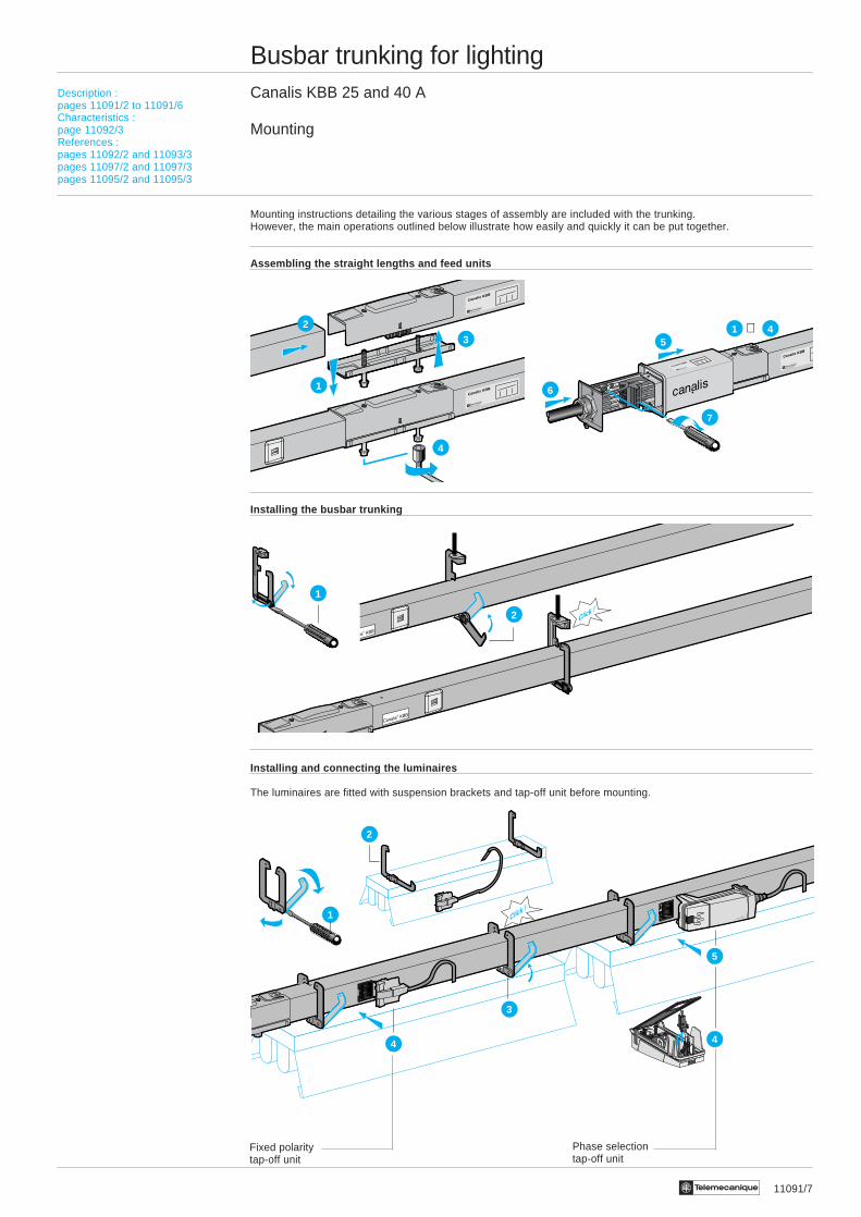
11091/7Te
1
3
2
5
44
Click !
Busbar trunking for lightingCanalis KBB 25 and 40 A
Mounting
Mounting instructions detailing the various stages of assembly are included with the trunking.However, the main operations outlined below illustrate how easily and quickly it can be put together.
Assembling the straight lengths and feed units
Installing the busbar trunking
Installing and connecting the luminaires
The luminaires are fitted with suspension brackets and tap-off unit before mounting.
1 4
6
5
7
⇒
Canalis KBB
Canalis KBB
3
4
2
1
Choix :page 11003/2Caractéristiques :page 11003/3Références :pages 11004/3 et 11005/2Encombrements :page 11005/3
Description :pages 11091/2 to 11091/6Characteristics :page 11092/3References :pages 11092/2 and 11093/3pages 11097/2 and 11097/3pages 11095/2 and 11095/3
Phase selectiontap-off unit
Fixed polaritytap-off unit
Click !2
1

11092/2 Te
Busbar trunking for lightingCanalis KBB 25 and 40 A
Installation study
Selecting the busbar trunking
Knowing :i The type of luminaire (types of lamp, power, compensatedor not), their weight, number and distributioni The structure of the premises (option of mountingbusbar trunking)i External influences (IP degree required)
Reminder of the various stages of selecting the busbar trunking (See the selection and study guides on pages0120Q/3 and 11068/2 to 11068/11).
i Select the type of busbar trunking depending on the possible fixing distance and/or the weight of the luminaires.i Select the number of circuits (KBB with 1 or 2 circuits).i Select the number of live conductors depending on the distribution scheme chosen or the number of lighting circuits.i Select the Inc rating depending on the operating current.i Select the power supply cable (type and cross-section) depending on the operating current and the type of protectionagainst overloads.i Check the voltage drops .i Select the type of protection against short-circuits and its coordination with the busbar trunking.
Option T : remote control circuit
This U < 50 V (SELV) circuit is used for the remote control of equipment fed by the main circuit on the busbar trunking(on the front of KBB trunking with 2 circuits).Its main uses include control of automatic emergency lighting circuits and remote dimmer control.
Option W : white lacquer finish (RAL 9010)
For installation in locations where aesthetic design is of particular importance (retail outlet, exhibition halls, etc).
Feed boxes
For KBB with 1 circuit : the terms “left” and “right” are given in relation to the busbar trunking reference face (front, end fittedwith 3 tap-off outlets).For KBB with 2 circuits : can be mounted at either end.
Flexible lengths
These are used to change the direction (nominal length = 500 mm) and level or to go round obstacles* (nominal length= 2 m).* This configuration can also be achieved using two feed boxes and an appropriately sized flexible cable. In this case,an additional jointing device must be provided (KBB-40YAA4) to be fitted at the right end of the first section of the run.
Installing and fixing the busbar trunking
The normal position for mounting is edgewise.The fixing distance depends on the weight of the luminaires suspended between 2 fixing points and must not exceed 5 m *.* This fixing distance can be increased to 6 m if the busbar trunking does not have any luminaires (equipment fixed to thestructure of the building) or if the luminaires are suspended on the straight part of a trunking mounting.
Selecting the tap-off units
Tap-off units are always single-phase L + N + PE or 2L + PE.Their selection depends on the functions required during installation and operation.
Selection criteria Fixed polarity Polarity with phase selectionPre-wired (H05VVF 1.5 mm2) With terminals FusedKBC-10CS KBC-16CB KBC-16CF
Simplicity/cost tEquipment suspended below the trunking tEquipment fixed to the framework (exc. trunking) t tOpen-ended installation (modification of scheme) t tSpecific cable (type, cross-section, length, etc) t tIndividual protection of the luminaire and cable tSelectivity of protection on a fault tRemote controlled equipment (option T) t t
Additional cable duct
The cable duct is designed mainly to receive the emergency lighting circuit cables which :- feed the equipment from a central source,- feed and/or control autonomous equipment (automatic emergency lighting units)It can also receive additional circuit cables such as telephone, audible alarm cables, etc.Distance between supports : 3 x 3 m supports are required.
Choix :page 11003/2Caractéristiques :page 11003/3Références :pages 11004/3 et 11005/2Encombrements :page 11005/3
Description :pages 11091/2 to 11091/6Characteristics :page 11092/3References :pages 11092/2 and 11093/3pages 11097/2 and 11097/3pages 11095/2 and 11095/3

11092/3Te
Busbar trunking for lightingCanalis KBB 25 and 40 A
Characteristics
Type of trunking KBB-25 KBB-40
General electrical characteristics
Conformity to standards IEC 439-2 and EN 60439-2
Number of live conductors 2 - 4 4 +2 4 +4 2 - 4 4 + 2 4 + 4
Number of circuits 1 2 2 1 2 2Inc per circuit (average ambient
Rated nominal current temperature 35°C) A 25 25 20 40 40 32
Operating currents for 2 circuits - 25 + 25 25 + 16 - 40 + 40 40 + 25
Type of current/rated frequency F Hz c 50/60 c 50/60
Rated insulation voltage Ui V 660 (2) 660 (2)
Rated operating voltage Ue V 230…400 230…400
Degree of protection conforming to IEC 529 IP 54 IP 54
Electrical characteristics of conductors
Live conductors R20 or Rb0 ph (1) average resistance, mΩ/m 6.83 2.93(per conductor) cold state (ambient temperature 20 °C)
R1 or Rb1 ph (1) average resistance mΩ/m 8.33 3.55at Inc (ambient temperature 35 °C)
X1 or Xb ph (1) average reactance mΩ/m 0.21 0.18at Inc and at 50 Hz rated frequency
Protective conductor Average resistance, cold state mΩ/m 0.80 0.80(ambient temperature 20 °C)
Fault loop characteristics
Average loop resistance Rb1 ph ph or ph N (at thermal mΩ/m 16.66 7.10between live connectors stabilisation temperature θ 1)
Rb2 ph ph or ph N (1) (at conventional mΩ/m 20.90 8.52short-circuit temperature)
Average loop reactance Xb ph ph mΩ/m 1.68 0.79
Xb ph N mΩ/m 2.08 0.83
Average loop resistance Rb1 ph PE (at thermal mΩ/m 9.08 3.81between live and PE conductors stabilisation temperature θ 1)
Rb2 ph PE (1) (at conventional mΩ/m 10.90 4.57short-circuit temperature)
Average loop reactance Xb ph PE mΩ/m 1.30 1.28
Other characteristics
Short-circuit current Ipk permissible rated peak current kA 4.40 9.60withstand II2t maximum thermal limit A2s 195.103 900.103
Voltage drop Voltage drop, for single-phase current 50 Hz, in volts per 100 m and per ampere with loads evenly distributedalong the run (general case for lighting).Voltage drop for 3-phase : multiply these values by 0.866.For Cos.ϕ = 0.8 V/100m/A 0.68 0.29For Cos.ϕ = 0.9 V/100m/A 0.76 0.33For Cos.ϕ = 1 V/100m/A 0.83 0.36
Normal mounting position Edgewise (side tap-off outlets)
Permissible current depending k1 uprating/derating multiplying factor to be applied to the desired rated current Inc of the busbar trunking for an averageon the temperature daily ambient temperature different to 35 °C.
Ambient temperature °C 15 20 25 30 35 40 45 50k1 factor 1.13 1.10 1.07 1.04 1.00 0.96 0.93 0.89
(1) In accordance with CENELEC document RO 64-003. (2) 500 V for busbar trunking fitted with option T and for 16 A tap-off units (KBC-16)
Description :pages 11091/2 to 11091/6Mounting and installation study :pages 11091/7 and 11092/2References :pages 11093/2 and 11093/3pages 11097/2 and 11097/3pages 11095/2 and 11095/3
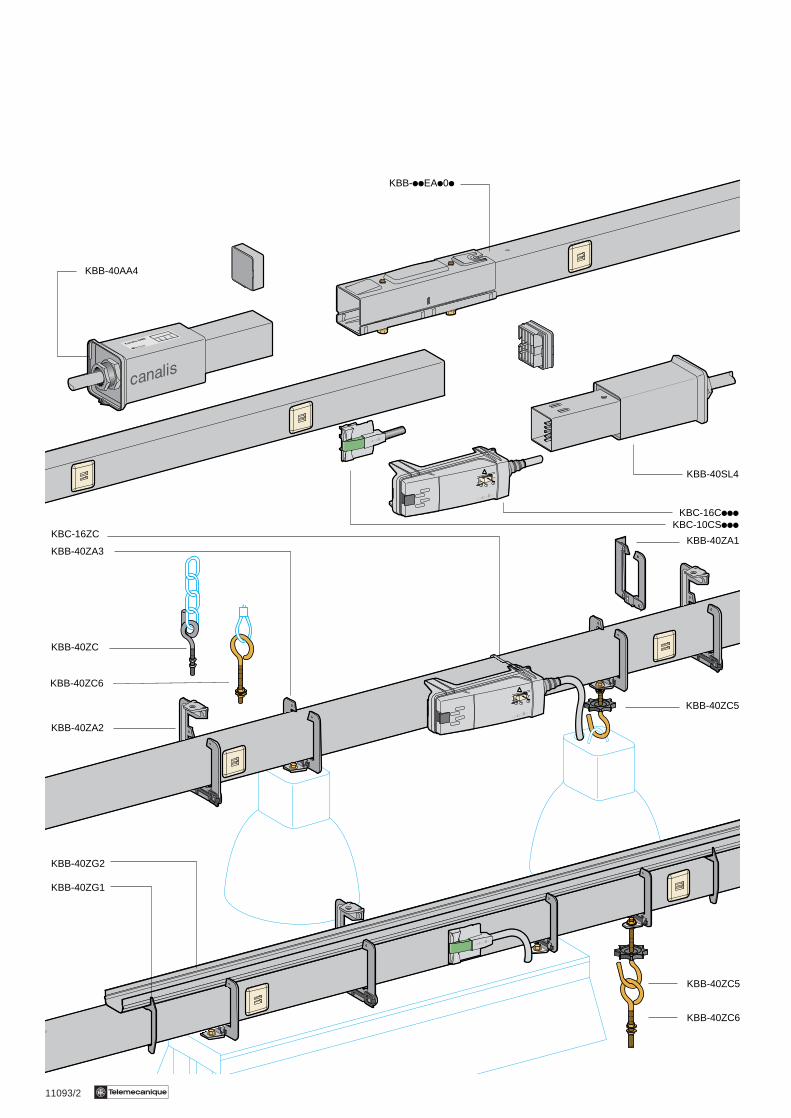
11093/2 Te
KBB-40AA4
KBB-iiEAi0i
KBB-40ZA3
KBC-16ZC
KBC-16CiiiKBC-10CSiii
KBB-40ZC
KBB-40ZA2
KBB-40ZG2
KBB-40ZG1
KBB-40ZA1
KBB-40SL4
KBB-40ZC5
KBB-40ZC6
KBB-40ZC5
KBB-40ZC6
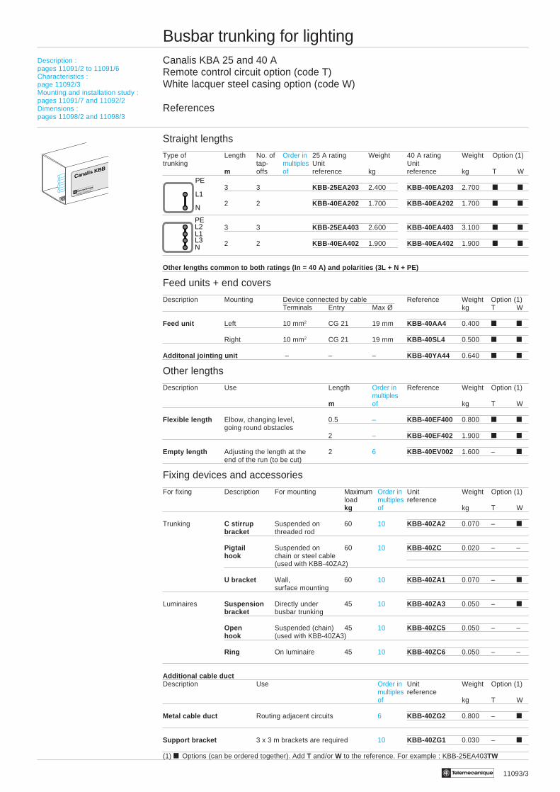
11093/3Te
Busbar trunking for lightingCanalis KBA 25 and 40 ARemote control circuit option (code T)White lacquer steel casing option (code W)
References
Straight lengths
Type of Length No. of Order in 25 A rating Weight 40 A rating Weight Option (1)trunking tap- multiples Unit Unit
m offs of reference kg reference kg T W
3 3 KBB-25EA203 2.400 KBB-40EA203 2.700 t t
2 2 KBB-40EA202 1.700 KBB-40EA202 1.700 t t
3 3 KBB-25EA403 2.600 KBB-40EA403 3.100 t t
2 2 KBB-40EA402 1.900 KBB-40EA402 1.900 t t
Other lengths common to both ratings (In = 40 A) and polarities (3L + N + PE)
Feed units + end covers
Description Mounting Device connected by cable Reference Weight Option (1)Terminals Entry Max Ø kg T W
Feed unit Left 10 mm2 CG 21 19 mm KBB-40AA4 0.400 t t
Right 10 mm2 CG 21 19 mm KBB-40SL4 0.500 t t
Additonal jointing unit – – – KBB-40YA44 0.640 t t
Other lengths
Description Use Length Order in Reference Weight Option (1)multiples
m of kg T W
Flexible length Elbow, changing level, 0.5 – KBB-40EF400 0.800 t tgoing round obstacles
2 – KBB-40EF402 1.900 t t
Empty length Adjusting the length at the 2 6 KBB-40EV002 1.600 – tend of the run (to be cut)
Fixing devices and accessories
For fixing Description For mounting Maximum Order in Unit Weight Option (1)load multiples referencekg of kg T W
Trunking C stirrup Suspended on 60 10 KBB-40ZA2 0.070 – tbracket threaded rod
Pigtail Suspended on 60 10 KBB-40ZC 0.020 – –hook chain or steel cable
(used with KBB-40ZA2)
U bracket Wall, 60 10 KBB-40ZA1 0.070 – tsurface mounting
Luminaires Suspension Directly under 45 10 KBB-40ZA3 0.050 – tbracket busbar trunking
Open Suspended (chain) 45 10 KBB-40ZC5 0.050 – –hook (used with KBB-40ZA3)
Ring On luminaire 45 10 KBB-40ZC6 0.050 – –
Additional cable ductDescription Use Order in Unit Weight Option (1)
multiples referenceof kg T W
Metal cable duct Routing adjacent circuits 6 KBB-40ZG2 0.800 – t
Support bracket 3 x 3 m brackets are required 10 KBB-40ZG1 0.030 – t
(1) t Options (can be ordered together). Add T and/or W to the reference. For example : KBB-25EA403TW
Description :pages 11091/2 to 11091/6Characteristics :page 11092/3Mounting and installation study :pages 11091/7 and 11092/2Dimensions :pages 11098/2 and 11098/3
Canalis KBB
N
L1
PE
N
L1L2
L3
PE
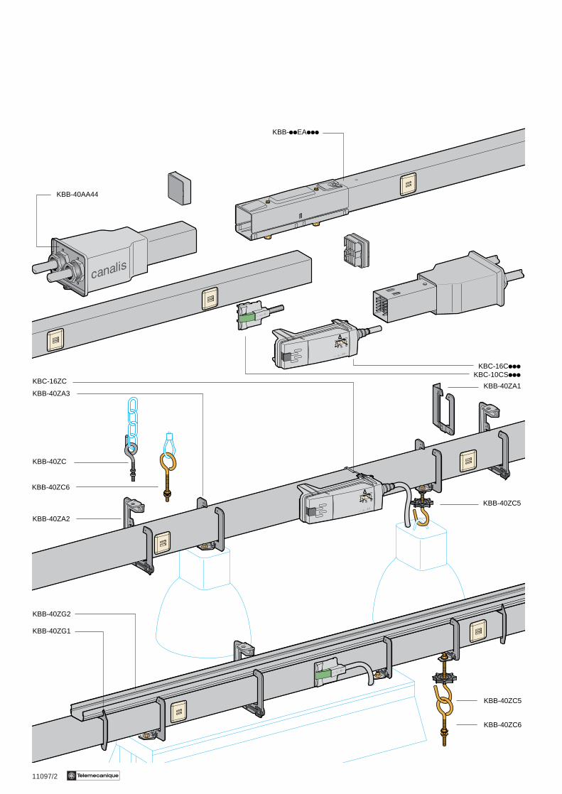
11097/2 Te
KBB-40AA44
KBB-iiEAiii
KBB-40ZA3
KBC-16ZC
KBC-16CiiiKBC-10CSiii
KBB-40ZC
KBB-40ZA2
KBB-40ZG2
KBB-40ZG1
KBB-40ZA1
KBB-40ZC5
KBB-40ZC6
KBB-40ZC5
KBB-40ZC6

11097/3Te
Busbar trunking for lightingCanalis KBB 25 and 40 ARemote control circuit option (code T)White lacquer steel casing option (code W)
References
Straight lengths
Type of Length No. of 25 A rating Weight 40 A rating Weight Option (1)trunking tap- Unit Unit
m offs reference kg reference kg T W
3 3 + 2 KBB-25EA223 4.600 KBB-40EA223 5.200 t t
2 2 + 1 KBB-40EA222 3.600 KBB-40EA222 3.600 t t
3 3 + 2 KBB-25EA423 4.700 KBB-40EA423 3.700 – t
2 2 + 1 KBB-40EA442 3.400 KBB-40EA442 3.400 – t
3 3 + 2 KBB-25EA443 4.800 KBB-40EA443 6.100 t t
2 2 + 1 KBB-40EA442 3.800 KBB-40EA442 3.800 t t
Other lengths common to both ratings (In = 40 A) and polarities (3L + N + PE)
Feed units + end covers
Description Mounting Device connected by cable Reference Weight Option (1)Terminals Entry Max Ø kg T W
Feed unit Left 10 mm2 CG 21 19 mm KBB-40AA44 0.400 t tor right
Specificfeed unit
Right For runs fitted with option “T” KBB-40SL44T 0.500 – t
Additional jointing unit KBB-40YA44 0.640 t t
Other lengths
Description Use Length Order in Reference Weight Option (1)multiples
m of kg T WFlexible length Elbow, changing level, 0.5 – KBB-40EF440 0.800 t t
going round obstacles 2 – KBB-40EF442 1.900 t tEmpty length Adjusting the length at the 2 6 KBB-40EV002 1.600 – t
end of the run (to be cut)
Fixing devices and accessories
For fixing Description For mounting Maximum Order in Unit Weight Option (1)load multiples referencekg of kg T W
Trunking C stirrup Suspended on 60 10 KBB-40ZA2 0.070 – tbracket threaded rod
Pigtail Suspended on 60 10 KBB-40ZC 0.020 – –hook chain or steel cable
(used with KBB-40ZA2)
U bracket Wall, 60 10 KBB-40ZA1 0.070 – tsurface mounting
Luminaires Suspension Directly under 45 10 KBB-40ZA3 0.050 – tbracket busbar trunking
Open Suspended (chain) 45 10 KBB-40ZC5 0.050 – –hook (used with KBB-40ZA3)
Ring On luminaire 45 10 KBB-40ZC6 0.050 – –
Additional cable ductDescription Use Order in Unit Weight Option (1)
multiples referenceof kg T W
Metal cable duct Routing adjacent circuits 6 KBB-40ZG2 0.800 – t
Support bracket 3 x 3 m brackets are required 10 KBB-40ZG1 0.030 – t(1) t Options (can be ordered together). Add T and/or W to the reference. For example : KBA-25EA403TW
N
L1L2
L3
PE
N
L1
PE
N
L1
PE
N
L1
PE
N
L1L3
L2
L3
L2PE
N
L1
PE
Canalis KBB
Description :pages 11091/2 to 11091/6Characteristics :page 11092/3Mounting and installation study : :pages 11091/7 and 11092/2Dimensions :pages 11098/2 and 11098/3

11095/2 Te
Busbar trunking for lightingCanalis KBB 25 and 40 ATap-off units
References
10 A units, 2-pole + PE pre-wired with H05-VVF 3 x 1.5 mm2 cable with fixed polarity
For trunking Polarity Lock/ Length Order in Unit Weight(distribution type) body of cable multiples reference
colour m of kg
L1 + N Green/grey 0.8 10 KBC-10CS101 0.100
2 10 KBC-10CS102 0.200Single lighting circuit L + N + PE
L1 + N Green/grey 0.8 10 KBC-10CS101 0.100
2 10 KBC-10CS102 0.200
L2 + N Yellow/grey 0.8 10 KBC-10CS201 0.100
2 10 KBC-10CS202 0.200Balanced on3 phasesor 3 lighting circuits L3 + N Brown/grey 0.8 10 KBC-10CS301 0.1003L + N + PE400/230 V 2 10 KBC-10CS302 0.200
L1 + L2 Green/black 0.8 10 KBC-10CS121 0.100
2 10 KBC-10CS122 0.200
L1 + L3 Yellow/black 0.8 10 KBC-10CS131 0.100
2 10 KBC-10CS132 0.200
Balanced on3 phases L2 + L3 Brown/black 0.8 10 KBC-10CS231 0.1003L + PE without N3 X 230 V 2 10 KBC-10CS232 0.200
L2 + N2 Green/black 0.8 10 KBC-10CS121 0.100
2 10 KBC-10CS122 0.200
2 single-phasecircuits L3 + N3 Brown/grey 0.8 10 KBC-10CS301 0.100L + N + PE230 V 2 10 KBC-10CS302 0.200
Additional accessories (for all types of tap-off unit)
Description Function Colour Order in Unit Weightmultiples referenceof kg
Outlet/tap-off unit Identification and Blue 20 KBC-16AZ1 0.002interlocking device mechanical locking(2 parts for between 1 to 3outlet and unit) different circuits White 20 KBC-16AZ2 0.002
Red 20 KBC-16AZ3 0.002
Replacement parts
Description Function Order in Unit Weightmultiples referenceof kg
Blanking plate Re-establish IP 54 on the tap-off outlet 10 KBC-16ZB 0.005if original blanking plate is lost.
Description :pages 11091/2 to 11091/6Characteristics :page 11092/3Mounting and installation study :pages 11091/7 and 11092/2Dimensions:pages 11098/2 and 11098/3
N
L1
PE
NL3L1L2PE
L3N3
N2L2PE
KBC-16AZi
KBC-10CSiii
KBC-10CSiii
KBC-16ZB
L3L1L2PE

11095/3Te
Busbar trunking for lightingCanalis KBB 25 and 40 ATap-off units
References
16 A single-phase units, L + N + PE, with phase selection
For trunking Polarity Protection Scheme Lock Order in Unit Weight(distribution type) colour multiples reference
of kg
L1 + N No Blue 10 KBC-16CB21 0.090
orSingle lighting circuitL + N + PE L2 + N
or By fuse Blue 10 KBC-16CF21 0.090(1)
L3 + N
Balanced on3 phases or3 lighting circuits3L + N + PE
16 A two-phase units, 2L + PE, with phase selection
For trunking Polarity Protection Scheme Lock Order in Unit Weight(distribution type) colour multiples reference
of kg
L1 + L2 No Yellow 10 KBC-16CB22 0.090
or
L2 + L3Balanced on By fuses Yellow 10 KBC-16CF22 0.0903 phases or (1)3L + PE without N3 X 230 V L1 + L3
16 A single-phase units, L + N + PE, with preset polarity
For trunking Polarity Protection Scheme Lock Order in Unit Weight(distribution type) colour multiples reference
of kg
L2 +N2 No Blue 10 KBC-16CB226 0.090
2 single-phasecircuits L3 + N3 No Blue 10 KBC-16CB216 0.090L + N + PE230 V
L2 + N2 By fuse Blue 10 KBC-16CF226 0.090(1)
L3 + N3 By fuse Blue 10 KBC-16CF216 0.090(1)
Additional accessories (specific to KBC-16iiii units)
Description Function Order in Unit Weight(distribution type) multiples reference
of kg
Contact block Tap-off on trunking bus to the receiver 10 KBC-16AZ01 0.010(to be used with KBC-16CB2i/CF21)
Rear support bracket Clamps the tap-off unit to the trunking 10 KBC-16ZC 0.020(to be used with KBC-16CB2i/CF2i)
(1) Cylindrical fuse NF 8.5 X 31.5 - 16 A gG max. not supplied.
N L3 L1 L2 PE
KBC-16CBiiiKBC-16CFiii
KBC-16AZ01
N
L1PE
NL3L1L2PE
L3N3
N2L2PE
123
!
KBC-16ZC
L3L1L2PE L3 L1 L2 P
E
N3
L3 N2
L2 PE
Description :pages 11091/2 to 11091/6Characteristics :page 11092/3Mounting and installation study :pages 11091/7 and 11092/2Dimensions :pages 11098/2 and 11098/3

11098/2 Te
Busbar trunking for lightingCanalis KBB (25 and 40 A)
Dimensions
Straight lengths KBB- iiEAiii
Flexible lengths KBB-40EF ii (1)
KBB- Nominal length Flexible lengthA B
40EF4i0 488 15340EF4i2 1988 1653
(1) Minimum bending radius : 70 mmFeed unit and end coverKBB-40AA4 KBB-40SL4
KBB-40AA44 End cover (supplied with feed unit)
46 30
46
B
A
75,5141
75,5
244
141
244
103,5141
244
75,5
500100 500
3000
1000 1000
10001000
51
60
46
46
Description :pages 11091/2 to 11091/6Characteristics :page 11092/3References :pages 11092/2 and 11093/3pages 11097/2 and 11097/3pages 11095/2 and 11095/3
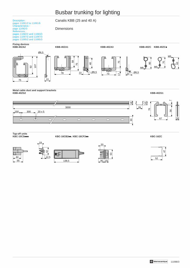
11098/3Te
Busbar trunking for lightingCanalis KBB (25 and 40 A)
Dimensions
Fixing devicesKBB-40ZA2 KBB-40ZA1 KBB-40ZA3 KBB-40ZC KBB-40ZC i
Metal cable duct and support bracketsKBB-40ZG2 KBB-40ZG1
Tap-off unitsKBC-10CSiii KBC-16CB2 ii, KBC-16CF2ii KBC-16ZC
62
M5
52
47
263000
14 14
300150 20 x 5
30
80
M6
70
M5
12,5
19
44
55
42
75
92 107
22
Ø6,5
78 2258
75 48
Ø6,573 22
7517
Ø6,5
3330
20
138,5
53
1667
567
76
Description :pages 11091/2 to 11091/6Characteristics :page 11092/3References :pages 11092/2 and 11093/3pages 11097/2 and 11097/3pages 11095/2 and 11095/3

11096/2 Te
Busbar trunking for lightingSpecific applications
Emergency lighting
Automatic emergency lighting units
Choice of Canalis KBA or KBB busbar trunking with 4 conductors + remote control KBi-iiEA403T.The L2 and N2 conductors are used to power the luminaires for normal lighting. The L3 and N3 conductors are used topower the 230 V emergency lighting units. The remote control conductors are used to control the emergency lighting units.
Connection of luminaires for normal lightingUse the KBC-10CS12i moulded connector (yellow lock, black body).
Connection of the emergency lightingUse the connection unit on KBC-16CB216 terminals (selection L3/N3) equipped with the additional power socket blockfor the KBC-16AZ01 remote control (connection of the control circuit of the automatic emergency lighting units).
Supply tonormal lighting
Supply toemergency lighting
Control circuit foremergency lighting
EXTINCTION
ALLUMAGETELECOMMANDE BAES
L2
N2
L3
N3
EXTINCTION
ALLUMAGE
TELECOMMANDE BAES

11096/3Te
Busbar trunking for lightingSpecific applications
Emergency lighting
Emergency lighting from a central source
Choice of Canalis KBA or KBB fitted with a metal cable duct with 26 x 14 mm usable size.The busbar trunking is used to supply luminaires for normal lighting (1 lighting circuit in the example below). The duct isused for routing emergency lighting.
Connection of luminaires for normal lightingWith a moulded connector KBC-10CS10i (green lock, grey body).
Connection of luminaires for emergency lightingUse either a KBB-40ES2* emergency lighting distribution box fixed to the busbar trunking by two Kii-40ZA2 devices, withthe luminaire fed by a KBC10CS10i tap-off unit.Or a traditional distribution box.* The KBB-40ES2 box provides a tap-off without breaking the emergency lighting cable. Designed around tap-off units, itenables maintenance operations to be carried out without affecting the continuity of service of the emergency lighting.
Emergency lighting : central sourceNormal lighting
Alimentation éclairage normal
N
Eclairage de sécurité
Eclairagede sécurité
Eclairagenormal
L1
Emergency lighting
Supply tonormal lighting
Emergencylighting
Normallighting