canadian meccanotes 200703 - cmamas.ca · march 2007 canadian meccanotes 3 desired, your material...
TRANSCRIPT

CanadianCanadianCanadianCanadianCanadian
MeccaNotesMeccaNotesMeccaNotesMeccaNotesMeccaNotes
--- Issue #45 ------ Issue #45 ------ Issue #45 ------ Issue #45 ------ Issue #45 ---
Mar. 2007Mar. 2007Mar. 2007Mar. 2007Mar. 2007
Horse Buggy and SleighHorse Buggy and SleighHorse Buggy and SleighHorse Buggy and SleighHorse Buggy and SleighHere are two pictures of a horse and buggy and a sleigh.I was most pleased with the two lines between the manand the horse. I guess it is the shadow of the light, samewith the sleigh. What I did is to put a small wheel in thesleigh runners so it would pull along easy. I used a M56 speed motor. If we set the motor at a low speed thehorse will walk slow; if we change the motor speed tohigh the horse will run. The horse is a little bigger thanthe horse Andreas Konkoly built.
Emile Amirault

2 Canadian MeccaNotes2 Canadian MeccaNotes2 Canadian MeccaNotes2 Canadian MeccaNotes2 Canadian MeccaNotes March 2007March 2007March 2007March 2007March 2007
... continued on page 3
123456789012345678901234567890121234567890123456789012345678901212341234567890123456789012345678901212345678901234567890123456789012123412345678901234567890123456789012123456789012345678901234567890121234123456789012345678901234567890121234567890123456789012345678901212341234567890123456789012345678901212345678901234567890123456789012123412345678901234567890123456789012123456789012345678901234567890121234123456789012345678901234567890121234567890123456789012345678901212341234567890123456789012345678901212345678901234567890123456789012123412345678901234567890123456789012123456789012345678901234567890121234123456789012345678901234567890121234567890123456789012345678901212341234567890123456789012345678901212345678901234567890123456789012123412345678901234567890123456789012123456789012345678901234567890121234123456789012345678901234567890121234567890123456789012345678901212341234567890123456789012345678901212345678901234567890123456789012123412345678901234567890123456789012123456789012345678901234567890121234123456789012345678901234567890121234567890123456789012345678901212341234567890123456789012345678901212345678901234567890123456789012123412345678901234567890123456789012123456789012345678901234567890121234123456789012345678901234567890121234567890123456789012345678901212341234567890123456789012345678901212345678901234567890123456789012123412345678901234567890123456789012123456789012345678901234567890121234123456789012345678901234567890121234567890123456789012345678901212341234567890123456789012345678901212345678901234567890123456789012123412345678901234567890123456789012123456789012345678901234567890121234123456789012345678901234567890121234567890123456789012345678901212341234567890123456789012345678901212345678901234567890123456789012123412345678901234567890123456789012123456789012345678901234567890121234123456789012345678901234567890121234567890123456789012345678901212341234567890123456789012345678901212345678901234567890123456789012123412345678901234567890123456789012123456789012345678901234567890121234123456789012345678901234567890121234567890123456789012345678901212341234567890123456789012345678901212345678901234567890123456789012123412345678901234567890123456789012123456789012345678901234567890121234123456789012345678901234567890121234567890123456789012345678901212341234567890123456789012345678901212345678901234567890123456789012123412345678901234567890123456789012123456789012345678901234567890121234123456789012345678901234567890121234567890123456789012345678901212341234567890123456789012345678901212345678901234567890123456789012123412345678901234567890123456789012123456789012345678901234567890121234123456789012345678901234567890121234567890123456789012345678901212341234567890123456789012345678901212345678901234567890123456789012123412345678901234567890123456789012123456789012345678901234567890121234123456789012345678901234567890121234567890123456789012345678901212341234567890123456789012345678901212345678901234567890123456789012123412345678901234567890123456789012123456789012345678901234567890121234123456789012345678901234567890121234567890123456789012345678901212341234567890123456789012345678901212345678901234567890123456789012123412345678901234567890123456789012123456789012345678901234567890121234123456789012345678901234567890121234567890123456789012345678901212341234567890123456789012345678901212345678901234567890123456789012123412345678901234567890123456789012123456789012345678901234567890121234123456789012345678901234567890121234567890123456789012345678901212341234567890123456789012345678901212345678901234567890123456789012123412345678901234567890123456789012123456789012345678901234567890121234123456789012345678901234567890121234567890123456789012345678901212341234567890123456789012345678901212345678901234567890123456789012123412345678901234567890123456789012123456789012345678901234567890121234123456789012345678901234567890121234567890123456789012345678901212341234567890123456789012345678901212345678901234567890123456789012123412345678901234567890123456789012123456789012345678901234567890121234123456789012345678901234567890121234567890123456789012345678901212341234567890123456789012345678901212345678901234567890123456789012123412345678901234567890123456789012123456789012345678901234567890121234123456789012345678901234567890121234567890123456789012345678901212341234567890123456789012345678901212345678901234567890123456789012123412345678901234567890123456789012123456789012345678901234567890121234123456789012345678901234567890121234567890123456789012345678901212341234567890123456789012345678901212345678901234567890123456789012123412345678901234567890123456789012123456789012345678901234567890121234123456789012345678901234567890121234567890123456789012345678901212341234567890123456789012345678901212345678901234567890123456789012123412345678901234567890123456789012123456789012345678901234567890121234123456789012345678901234567890121234567890123456789012345678901212341234567890123456789012345678901212345678901234567890123456789012123412345678901234567890123456789012123456789012345678901234567890121234123456789012345678901234567890121234567890123456789012345678901212341234567890123456789012345678901212345678901234567890123456789012123412345678901234567890123456789012123456789012345678901234567890121234123456789012345678901234567890121234567890123456789012345678901212341234567890123456789012345678901212345678901234567890123456789012123412345678901234567890123456789012123456789012345678901234567890121234123456789012345678901234567890121234567890123456789012345678901212341234567890123456789012345678901212345678901234567890123456789012123412345678901234567890123456789012123456789012345678901234567890121234123456789012345678901234567890121234567890123456789012345678901212341234567890123456789012345678901212345678901234567890123456789012123412345678901234567890123456789012123456789012345678901234567890121234123456789012345678901234567890121234567890123456789012345678901212341234567890123456789012345678901212345678901234567890123456789012123412345678901234567890123456789012123456789012345678901234567890121234123456789012345678901234567890121234567890123456789012345678901212341234567890123456789012345678901212345678901234567890123456789012123412345678901234567890123456789012123456789012345678901234567890121234123456789012345678901234567890121234567890123456789012345678901212341234567890123456789012345678901212345678901234567890123456789012123412345678901234567890123456789012123456789012345678901234567890121234123456789012345678901234567890121234567890123456789012345678901212341234567890123456789012345678901212345678901234567890123456789012123412345678901234567890123456789012123456789012345678901234567890121234123456789012345678901234567890121234567890123456789012345678901212341234567890123456789012345678901212345678901234567890123456789012123412345678901234567890123456789012123456789012345678901234567890121234123456789012345678901234567890121234567890123456789012345678901212341234567890123456789012345678901212345678901234567890123456789012123412345678901234567890123456789012123456789012345678901234567890121234123456789012345678901234567890121234567890123456789012345678901212341234567890123456789012345678901212345678901234567890123456789012123412345678901234567890123456789012123456789012345678901234567890121234123456789012345678901234567890121234567890123456789012345678901212341234567890123456789012345678901212345678901234567890123456789012123412345678901234567890123456789012123456789012345678901234567890121234123456789012345678901234567890121234567890123456789012345678901212341234567890123456789012345678901212345678901234567890123456789012123412345678901234567890123456789012123456789012345678901234567890121234123456789012345678901234567890121234567890123456789012345678901212341234567890123456789012345678901212345678901234567890123456789012123412345678901234567890123456789012123456789012345678901234567890121234123456789012345678901234567890121234567890123456789012345678901212341234567890123456789012345678901212345678901234567890123456789012123412345678901234567890123456789012123456789012345678901234567890121234123456789012345678901234567890121234567890123456789012345678901212341234567890123456789012345678901212345678901234567890123456789012123412345678901234567890123456789012123456789012345678901234567890121234123456789012345678901234567890121234567890123456789012345678901212341234567890123456789012345678901212345678901234567890123456789012123412345678901234567890123456789012123456789012345678901234567890121234123456789012345678901234567890121234567890123456789012345678901212341234567890123456789012345678901212345678901234567890123456789012123412345678901234567890123456789012123456789012345678901234567890121234123456789012345678901234567890121234567890123456789012345678901212341234567890123456789012345678901212345678901234567890123456789012123412345678901234567890123456789012123456789012345678901234567890121234123456789012345678901234567890121234567890123456789012345678901212341234567890123456789012345678901212345678901234567890123456789012123412345678901234567890123456789012123456789012345678901234567890121234123456789012345678901234567890121234567890123456789012345678901212341234567890123456789012345678901212345678901234567890123456789012123412345678901234567890123456789012123456789012345678901234567890121234123456789012345678901234567890121234567890123456789012345678901212341234567890123456789012345678901212345678901234567890123456789012123412345678901234567890123456789012123456789012345678901234567890121234123456789012345678901234567890121234567890123456789012345678901212341234567890123456789012345678901212345678901234567890123456789012123412345678901234567890123456789012123456789012345678901234567890121234123456789012345678901234567890121234567890123456789012345678901212341234567890123456789012345678901212345678901234567890123456789012123412345678901234567890123456789012123456789012345678901234567890121234123456789012345678901234567890121234567890123456789012345678901212341234567890123456789012345678901212345678901234567890123456789012123412345678901234567890123456789012123456789012345678901234567890121234123456789012345678901234567890121234567890123456789012345678901212341234567890123456789012345678901212345678901234567890123456789012123412345678901234567890123456789012123456789012345678901234567890121234123456789012345678901234567890121234567890123456789012345678901212341234567890123456789012345678901212345678901234567890123456789012123412345678901234567890123456789012123456789012345678901234567890121234123456789012345678901234567890121234567890123456789012345678901212341234567890123456789012345678901212345678901234567890123456789012123412345678901234567890123456789012123456789012345678901234567890121234123456789012345678901234567890121234567890123456789012345678901212341234567890123456789012345678901212345678901234567890123456789012123412345678901234567890123456789012123456789012345678901234567890121234123456789012345678901234567890121234567890123456789012345678901212341234567890123456789012345678901212345678901234567890123456789012123412345678901234567890123456789012123456789012345678901234567890121234123456789012345678901234567890121234567890123456789012345678901212341234567890123456789012345678901212345678901234567890123456789012123412345678901234567890123456789012123456789012345678901234567890121234123456789012345678901234567890121234567890123456789012345678901212341234567890123456789012345678901212345678901234567890123456789012123412345678901234567890123456789012123456789012345678901234567890121234123456789012345678901234567890121234567890123456789012345678901212341234567890123456789012345678901212345678901234567890123456789012123412345678901234567890123456789012123456789012345678901234567890121234123456789012345678901234567890121234567890123456789012345678901212341234567890123456789012345678901212345678901234567890123456789012123412345678901234567890123456789012123456789012345678901234567890121234
123456789012345678901234567890121234567890123456789012345678901212345123456789012345678901234567890121234567890123456789012345678901212345123456789012345678901234567890121234567890123456789012345678901212345123456789012345678901234567890121234567890123456789012345678901212345123456789012345678901234567890121234567890123456789012345678901212345123456789012345678901234567890121234567890123456789012345678901212345123456789012345678901234567890121234567890123456789012345678901212345123456789012345678901234567890121234567890123456789012345678901212345123456789012345678901234567890121234567890123456789012345678901212345123456789012345678901234567890121234567890123456789012345678901212345123456789012345678901234567890121234567890123456789012345678901212345123456789012345678901234567890121234567890123456789012345678901212345123456789012345678901234567890121234567890123456789012345678901212345123456789012345678901234567890121234567890123456789012345678901212345123456789012345678901234567890121234567890123456789012345678901212345123456789012345678901234567890121234567890123456789012345678901212345123456789012345678901234567890121234567890123456789012345678901212345123456789012345678901234567890121234567890123456789012345678901212345123456789012345678901234567890121234567890123456789012345678901212345123456789012345678901234567890121234567890123456789012345678901212345123456789012345678901234567890121234567890123456789012345678901212345123456789012345678901234567890121234567890123456789012345678901212345123456789012345678901234567890121234567890123456789012345678901212345123456789012345678901234567890121234567890123456789012345678901212345123456789012345678901234567890121234567890123456789012345678901212345123456789012345678901234567890121234567890123456789012345678901212345123456789012345678901234567890121234567890123456789012345678901212345123456789012345678901234567890121234567890123456789012345678901212345123456789012345678901234567890121234567890123456789012345678901212345123456789012345678901234567890121234567890123456789012345678901212345123456789012345678901234567890121234567890123456789012345678901212345123456789012345678901234567890121234567890123456789012345678901212345123456789012345678901234567890121234567890123456789012345678901212345123456789012345678901234567890121234567890123456789012345678901212345123456789012345678901234567890121234567890123456789012345678901212345123456789012345678901234567890121234567890123456789012345678901212345123456789012345678901234567890121234567890123456789012345678901212345123456789012345678901234567890121234567890123456789012345678901212345123456789012345678901234567890121234567890123456789012345678901212345123456789012345678901234567890121234567890123456789012345678901212345123456789012345678901234567890121234567890123456789012345678901212345123456789012345678901234567890121234567890123456789012345678901212345123456789012345678901234567890121234567890123456789012345678901212345123456789012345678901234567890121234567890123456789012345678901212345123456789012345678901234567890121234567890123456789012345678901212345123456789012345678901234567890121234567890123456789012345678901212345123456789012345678901234567890121234567890123456789012345678901212345123456789012345678901234567890121234567890123456789012345678901212345123456789012345678901234567890121234567890123456789012345678901212345123456789012345678901234567890121234567890123456789012345678901212345123456789012345678901234567890121234567890123456789012345678901212345123456789012345678901234567890121234567890123456789012345678901212345123456789012345678901234567890121234567890123456789012345678901212345123456789012345678901234567890121234567890123456789012345678901212345123456789012345678901234567890121234567890123456789012345678901212345123456789012345678901234567890121234567890123456789012345678901212345123456789012345678901234567890121234567890123456789012345678901212345123456789012345678901234567890121234567890123456789012345678901212345123456789012345678901234567890121234567890123456789012345678901212345123456789012345678901234567890121234567890123456789012345678901212345123456789012345678901234567890121234567890123456789012345678901212345123456789012345678901234567890121234567890123456789012345678901212345123456789012345678901234567890121234567890123456789012345678901212345123456789012345678901234567890121234567890123456789012345678901212345123456789012345678901234567890121234567890123456789012345678901212345123456789012345678901234567890121234567890123456789012345678901212345123456789012345678901234567890121234567890123456789012345678901212345123456789012345678901234567890121234567890123456789012345678901212345123456789012345678901234567890121234567890123456789012345678901212345123456789012345678901234567890121234567890123456789012345678901212345123456789012345678901234567890121234567890123456789012345678901212345123456789012345678901234567890121234567890123456789012345678901212345123456789012345678901234567890121234567890123456789012345678901212345123456789012345678901234567890121234567890123456789012345678901212345123456789012345678901234567890121234567890123456789012345678901212345123456789012345678901234567890121234567890123456789012345678901212345123456789012345678901234567890121234567890123456789012345678901212345123456789012345678901234567890121234567890123456789012345678901212345
SubscriptionsSubscriptionsSubscriptionsSubscriptionsSubscriptions
(4 Issues Per Calendar Year)(4 Issues Per Calendar Year)(4 Issues Per Calendar Year)(4 Issues Per Calendar Year)(4 Issues Per Calendar Year)
o within North America: Canada - $40; U.S.A.- US$40. Make cheque or money order payableto CMAMAS, mail to Treasurer, address above.
o elsewhere: £33, US$63 or C$70
o payment via PayPal is available, contactColin Hoare for details
© Copyright 2007 Copyright 2007 Copyright 2007 Copyright 2007 Copyright 2007C.M.A.M.A.S. and/or IndividualC.M.A.M.A.S. and/or IndividualC.M.A.M.A.S. and/or IndividualC.M.A.M.A.S. and/or IndividualC.M.A.M.A.S. and/or Individual
Contributors.Contributors.Contributors.Contributors.Contributors.Meccano and Erector are registered tradenames and are used throughout Canadian
MeccaNotes by kind permission of MeccanoLtd..
North American subscribers to CanadianMeccaNotes are automatically members of
the Canadian Modeling Association forMeccano and Allied Systems (CMAMAS).
CanadianCanadianCanadianCanadianCanadianMeccaNotesMeccaNotesMeccaNotesMeccaNotesMeccaNotes
The “Canadian MeccaNotes” newsletter(ISSN 1207-2249) is published 4 times peryear (March, June, September and December)by the Canadian Modeling Association forMeccano & Allied Systems (CMAMAS).
“Written and produced by Meccanoenthusiasts for Meccano enthusiasts.”
Canadian Modeling Association forCanadian Modeling Association forCanadian Modeling Association forCanadian Modeling Association forCanadian Modeling Association forMeccanoMeccanoMeccanoMeccanoMeccano & Allied Systems (CMAMAS) & Allied Systems (CMAMAS) & Allied Systems (CMAMAS) & Allied Systems (CMAMAS) & Allied Systems (CMAMAS)130 Neptune Drive, Suite 1109130 Neptune Drive, Suite 1109130 Neptune Drive, Suite 1109130 Neptune Drive, Suite 1109130 Neptune Drive, Suite 1109Toronto, OntarioToronto, OntarioToronto, OntarioToronto, OntarioToronto, OntarioCANADA M6A 1X5CANADA M6A 1X5CANADA M6A 1X5CANADA M6A 1X5CANADA M6A 1X5
http://www.cmamas.ca/http://www.cmamas.ca/http://www.cmamas.ca/http://www.cmamas.ca/http://www.cmamas.ca/
CMAMAS ExecutiveCMAMAS ExecutiveCMAMAS ExecutiveCMAMAS ExecutiveCMAMAS ExecutivePresidentPresidentPresidentPresidentPresident ... Colin Hoare, 18 Tweedle St.,Glen Williams, Ontario, Canada L7G 3S5,[email protected], (905)873-8261
Vice PresidentVice PresidentVice PresidentVice PresidentVice President ... Attila Szakonyi,10 Fendley Crt, Brampton, Ontario, Canada,L6Z 3H9, [email protected],(905)846-5287
TreasurerTreasurerTreasurerTreasurerTreasurer ... Marsha Brandston,130 Neptune Drive, Suite 1109, Toronto,Ontario, Canada M6A 1X5,[email protected]
SecretarySecretarySecretarySecretarySecretary ... Frank Curry, 8 Windham Drive,Toronto, Ontario, Canada M2K 1X8,[email protected], (416)221-3093
Newsletter Editor/WebmasterNewsletter Editor/WebmasterNewsletter Editor/WebmasterNewsletter Editor/WebmasterNewsletter Editor/Webmaster ... Dav idWilliams, 3017 - 111A Street, Edmonton,Alberta, Canada T6J 3Y5, [email protected],(780)438-1197
Parts & Sets Manager Parts & Sets Manager Parts & Sets Manager Parts & Sets Manager Parts & Sets Manager ... Dave Duncan,55 Lurgan Drive, Toronto, Ontario, CanadaM2R 1K7, [email protected],(416)733-8670
Editor’s NotesEditor’s NotesEditor’s NotesEditor’s NotesEditor’s NotesThis issue contains two model plans, one ofwhich will be continued next issue. Manythanks to Dave Duncan, Robin McLellan, MarshaBrandston, Emile Amirault, Colin Hoare, Rich-ard Symonds and others for supplying items forthis issue.
One contributor to each Cana-dian MeccaNotes issue gets aprize in appreciation of theirefforts. The December 2006winner was Ron Kurtz. Per-haps you’ll win for the nextissue? The prize is one of thenew CMAMAS flashlights.
Part of the CMAMAS websiteis now password protected.For example to see the meet-ings of minutes you now needthis id/password: cmember/Sprocket2.
As always, the newsletter is only as good as thecontributors. Your articles, photos, model plans,short news items, wants, sales and swap adsare wanted. Items in machine readable form (e-mail, CDROM) are preferred but everything isacceptable. If you scan photos, please scanthem at a minimum resolution of 150 dpi. If

March 2007March 2007March 2007March 2007March 2007 Canadian MeccaNotes 3Canadian MeccaNotes 3Canadian MeccaNotes 3Canadian MeccaNotes 3Canadian MeccaNotes 3
desired, your material can also be posted on ourwebsite. If you’d like any part of your submis-sions returned, please say so; otherwise I willkeep everything.
Please note that our CMAMAS website address(URL) has been changed to www.cmamas.ca.What would you like to see on the website?
Please note that we plan to publish the June2007 issue around June 7, 2007; the deadline isMay 25.
David Williams
2007 Meccano Show2007 Meccano Show2007 Meccano Show2007 Meccano Show2007 Meccano ShowDatesDatesDatesDatesDates
CMAMAS members will have a small exhibit (1table) at the 18th Kingston Rail O Rama March 17-18, 2007 10am-4pm at the Ambassador Confer-ence Centre, 1550 Princess St., Kingston. Take401 exit 613 south to Princess and go east onPrincess St. a half mile.
Moose Jaw Hobby Show and Swap Meet, Friday-Saturday, March 23-24, 2007. Contact Bill Bardutzfor further details ([email protected]).www.sukanenmuseum.ca
Quebec CMAMAS members will exhibit at Inter-national Toy Collectible and Nostalgia Show,Place Desaulniers, 1023 Boul. Taschereau,Longueuil Que J4K 2X5 April 14, 2007 9am -3:30pm.
CMAMAS members will exhibit at the Train & ToyShow at the W. B. George Centre, KemptvilleCollege, Kemptville, March 31-April 1, 2007, hoursSat 10am-5pm; Sun 10am-4pm. Seewww.antiquetoys.ca or contact Frank [email protected] (613) 634-8225 or HubertHogle, [email protected] (613) 532-3672
Quebec CMAMAS members will have a smallexhibit at Expo-Train-Modelisme show atPolyvalente George Vanier, 3995 Boul. Levesqueest, Laval, on April 14-15, 2007. Hours are 10am- 5pm Saturday and 10am - 4pm Sunday. Forfurther info check www.model-art.com.
The Toronto Toy, Train and Doll Collector Showwill be held on Sunday, April 22nd, 2007 from10:00 a.m. to 4:00 p.m. in Hall 6 at the Interna-tional Centre, 6900 Airport Road, Mississauga,and there will be a Meccano exhibit there. Set-uptimes are Saturday, April 21st from 6:00 p.m. to9:00 p.m. Contact Colin Hoare [email protected] to register and formore details.
The Fourth Hamilton Meccano Show is scheduledfor Waterworks Museum on July 28-29, 2007. Forfurther info. [email protected].
CMAMAS members will be displaying Meccanomodels again at the Thousand Islands ModelRailroaders show in Gananoque August 11-12,2007. The show is at the Gananoque RecreationCentre, 600 King St. E., 10 am - 4 pm. For moreinfo check www.festivaloftheislands.com or con-tact Hubert Hogle (613) 532-3672;[email protected].
The Canadian Toy Collectors Society show will beheld October 14, 2007 9am - 3pm at the SkywayTrade & Conference Centre, Dixon Road at Hwy 27Toronto. See www.ctcs.org or contact HubertHogle (613) 532-3672; [email protected].
CMAMAS will have a huge Meccano show at TheHobby Show at The International Centre, Torontoon November 2, 3 & 4, 2007. Hours are Friday,12 noon - 9 pm; Saturday, 10 am to 8 pm; Sunday,10 am to 6 pm. For more info checkwww.thehobbyshow.com or [email protected].
TTTTTable of Contentsable of Contentsable of Contentsable of Contentsable of Contents
Horse Buggy and Sleigh 1Editor’s Notes 22007 Meccano Show Dates 3Presidential Perusings 4March Bulk Order 5Toy Shoppe 2006 5Hot Reversing Mill 61915 Waterloo Boy Tractor Model R 11Borgfeldt (Canada) Ltd. 26The Peddler 27Richard Symonds’ Photos of Other Systems28

4 Canadian MeccaNotes4 Canadian MeccaNotes4 Canadian MeccaNotes4 Canadian MeccaNotes4 Canadian MeccaNotes March 2007March 2007March 2007March 2007March 2007
Presidential PerusingsPresidential PerusingsPresidential PerusingsPresidential PerusingsPresidential PerusingsMany subscribers to “Canadian MeccaNotes”make full use of a home computer, as is evident bythe fact that well over 80% of them have e-mailaddresses. No doubt the majority, at the veryleast, have explored e-Bay to look at what Meccanois being sold. In addition, many subscribe toSpanner, the Meccanochat line to monitor it.Certainly, I have boughtMeccano on e-Bay(among other things),and both read and occa-sionally contribute toSpanner.
One of the recent topicswith which I was in-volved was somethingthat went under theheading of ‘e-Bayrogues.’ The referencewas to those vendorswho offer something for an inexpensive price, butthen charge an incredible amount for shipping andhandling. Three vendors in particular were men-tioned, but I will refrain from citing the names forlegal reasons. I will, however, describe theexperience I had with one of them.
Up on offer were three 4" Thrust Bearing FlangedDiscs in black - probably repainted - for which thestarting price was £2.70, or around $6.25 Cana-dian. Being the only bidder, I won the lot. Asalways, the stipulation was that the purchasershould pay the shipping and handling costs,something that I was fully prepared to do. Otheritems of a similar nature and weight have beensent to me for £3.50, so this is what I expected topay. Imagine my reaction, therefore, when theinvoice indicated that the postage was £9.99, andthe handling fees were an additional £12.50,bringing the total to £25.68.
It goes without saying that I protested this amount.Before I had time to blink, or so it seemed, thevendor had filed a non-payment dispute with e-Bay. I contacted another C. M. A. M. A. S.member, who recalled that this vendor had beenreported on Spanner before for excessive postageand handling charges. I decided to follow theadvise of another contributor to Spanner - whoresides in Australia - and pay only for the item, andadvised the vendor not to bother to ship the item.By doing this, the contract of sale had been met.There was, of course, no guarantee that thiswould get me off the hook, so to speak.
The strategy worked. The dispute was closed -and, to my great surprise, the feedback from thevendor was the most effusive I have had fromanyone! (I should explain for non-users of e-Baythat, after an e-Bay sale has been concluded, boththe vendor is asked to provide feedback on thepurchaser, and vice versa).
So what happened? In my view, one of threepossible reasons: (a) the vendor is a ‘lurker’ onSpanner, and saw the uncomplimentary com-ments about his shipping and handling charges, or(b) he Googled my name on e-Bay, and saw myinvolvement with C. M. A. M. A. S., or (c) he gotwind of the fact that e-Bay was planning onreviewing all the vendors against whom com-plaints had been registered for charging excessiveprocessing fees. If any other subscriber to “Cana-dian MeccaNotes” has had a similar experience,I would be pleased to hear from them.
Finally, I would like to pay tribute to two individualswho passed away recently, whose names are wellknown in the Meccano world - even if one of themwas not known for his skills in Meccano model-ling.
The first person is Dave Feinstein from SouthAfrica. Dave was the Chairman of theJohannesburg Meccano Hobbyists, and had beenone of the driving forces in keeping Meccano in thepublic eye in his home city. The second is BillThacker, who passed away in December at theage of 91: Bill earned his living as a cartoonist,and, following his retirement, continued to providecartoons for hobby magazines. Bill became amajor contributor to “Constructor Quarterly,” themagazine that Robin Johnson publishes in En-gland. Bill would frequently attend the majorMeccano show in Skegness (SkegEx), and I recallthat I had the pleasure of meeting him there on atleast one occasion. I gather that Bill’s legacy willlive on for a while in “C. Q.” as he gave Robin asignificant collection of unpublished cartoonsshortly before he passed away. Bill came from anearlier era, when his humour was not subjected tothe pressures of political correctness. His witti-cism, however, was never malicious - just goodclean fun.
Colin Hoare

March 2007March 2007March 2007March 2007March 2007 Canadian MeccaNotes 5Canadian MeccaNotes 5Canadian MeccaNotes 5Canadian MeccaNotes 5Canadian MeccaNotes 5
March Bulk OrderMarch Bulk OrderMarch Bulk OrderMarch Bulk OrderMarch Bulk OrderHello fellow members, the March Bulk Orderhas been processed. Thanks to everyone whoplaced an order. I expect to ship to all clubmembers in April or early May. I have a goodfeeling about 2007, starting with the fact that Iam so pleased that I did not have to increase the
prices and that our sup-pliers are doing an ex-ceptional job. I have hadrequests for custommade parts, such asangle girders, channelgirders, long bolts, su-per short grub screws,and special borediameters for cou-plings. Our sup-pliers are morethan willing to ac-commodate theserequirements. Soif you need some-thing special,
please feel free to contact me to discuss.
I have some “French allen 4mm grubs instock, 5000 in total. One of our members,Doug Armstrong, informed me that thesegrubs hold bosses significantly betterthan the old type, so I decided to bring ina load. The club will selling them for$4.95 for 25, $19.25 for 100, and $96.00for 500.
I have an announcement for a very spe-cial prize draw that will take place at theNovember Show this year. There will be3 prizes drawn the grand one being a“Reproduction Set 9 in red/medium greenwith an Oak Cabinet. Tickets are ob-tained two ways. The first is 1 ticket for$50.00 or 3 for $100.00. The second wayis earned by purchasing ReproductionParts from the club. For every $500.00spent, the member shall receive a ticket.For example if member X spends$1650.00 throughout the year he or shewill earn 3 tickets. The March bulk orderis included, so many of you have ticketsalready. I will keep track of this andinform members of their status. Thetiming of this draw is perfect, just beforeChristmas and will be shipped to thewinner before Santa arrives. What a giftthis would make!
If you wish to purchase tickets, send the moneyto the usual address.
All the best and happy building.
David Duncan <[email protected]>
Toy Shoppe 2006Toy Shoppe 2006Toy Shoppe 2006Toy Shoppe 2006Toy Shoppe 2006Here are some photos of the window displayorganized by CMAMAS at the Toy Shoppe,Toronto in December 2006.
More pictures are on pages 26 and 27.

6 Canadian MeccaNotes6 Canadian MeccaNotes6 Canadian MeccaNotes6 Canadian MeccaNotes6 Canadian MeccaNotes March 2007March 2007March 2007March 2007March 2007
Hot Reversing MillHot Reversing MillHot Reversing MillHot Reversing MillHot Reversing MillBackgroundBackgroundBackgroundBackgroundBackground
The inspiration for this model came from theslabbing mill at Spencer Works, Llanwern, Wales.It was part of my orientation trip around the plantin 1967, prior to spending three years working atthe site.
This type of hot reversingmill takes pre-heated ingots(from the soaking pit) androlls them into slabs, whichthen go to a hot strip mill.Continuous slab casting isnow the preferred method ofmaking slabs.
The basic model was con-structed in 1989, and shownat the British Isles Show inToronto. The model was asuccess in that people of allages seemed to enjoy watch-ing it roll out the Plasticineingot. The roller table driveswere, however, not as effec-tive as I would have liked.The model then went to mybasement for quite sometime, and was rarely dusted
off. When this year’s Hamilton Show came up, Idecided to take it along, and pulled it out of myMeccano ‘junkyard’.
I looked at the engineering and was appalled bysome of it - perhaps I have learned a lot in the pastseventeen years! I started pulling out the rollertables and drives, knowing that I had four weeksto make something better. Several ideas were tried
out - and then panicset in, as my avail-able time was lim-ited. I completed thejob shortly before theshow. While still notentirely happy withthe results, they didoperate reliablythroughout the show.
What follows aresome notes and il-lustrations of the milland its mechanisms,rather than a full de-scription. I don’t seethe mill as a ‘clean’textbook type modelthat others mightwant to build featurefor feature, but someof the ideas might beof interest to otherconstructors.
March 2007March 2007March 2007March 2007March 2007 Canadian MeccaNotes 7Canadian MeccaNotes 7Canadian MeccaNotes 7Canadian MeccaNotes 7Canadian MeccaNotes 7
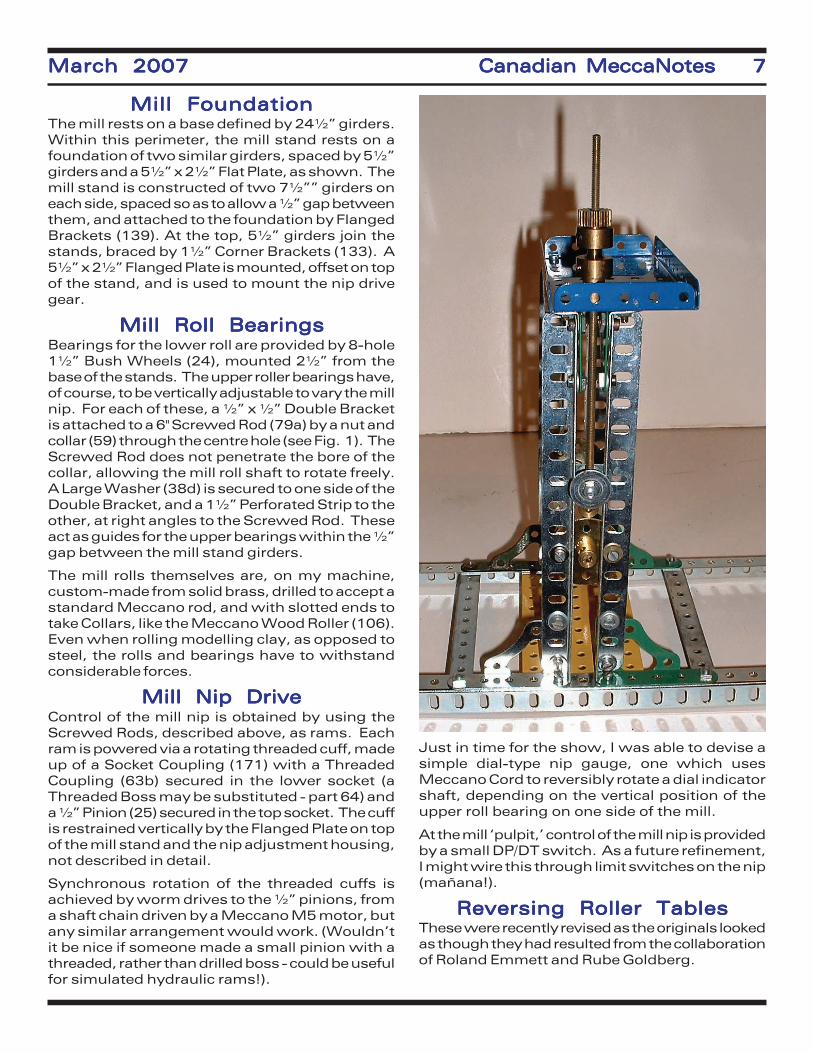
Mill FoundationMill FoundationMill FoundationMill FoundationMill FoundationThe mill rests on a base defined by 24½” girders.Within this perimeter, the mill stand rests on afoundation of two similar girders, spaced by 5½”girders and a 5½” x 2½” Flat Plate, as shown. Themill stand is constructed of two 7½”” girders oneach side, spaced so as to allow a ½” gap betweenthem, and attached to the foundation by FlangedBrackets (139). At the top, 5½” girders join thestands, braced by 1½” Corner Brackets (133). A5½” x 2½” Flanged Plate is mounted, offset on topof the stand, and is used to mount the nip drivegear.
Mill Roll BearingsMill Roll BearingsMill Roll BearingsMill Roll BearingsMill Roll BearingsBearings for the lower roll are provided by 8-hole1½” Bush Wheels (24), mounted 2½” from thebase of the stands. The upper roller bearings have,of course, to be vertically adjustable to vary the millnip. For each of these, a ½” x ½” Double Bracketis attached to a 6" Screwed Rod (79a) by a nut andcollar (59) through the centre hole (see Fig. 1). TheScrewed Rod does not penetrate the bore of thecollar, allowing the mill roll shaft to rotate freely.A Large Washer (38d) is secured to one side of theDouble Bracket, and a 1½” Perforated Strip to theother, at right angles to the Screwed Rod. Theseact as guides for the upper bearings within the ½”gap between the mill stand girders.
The mill rolls themselves are, on my machine,custom-made from solid brass, drilled to accept astandard Meccano rod, and with slotted ends totake Collars, like the Meccano Wood Roller (106).Even when rolling modelling clay, as opposed tosteel, the rolls and bearings have to withstandconsiderable forces.
Mill Nip DriveMill Nip DriveMill Nip DriveMill Nip DriveMill Nip DriveControl of the mill nip is obtained by using theScrewed Rods, described above, as rams. Eachram is powered via a rotating threaded cuff, madeup of a Socket Coupling (171) with a ThreadedCoupling (63b) secured in the lower socket (aThreaded Boss may be substituted - part 64) anda ½” Pinion (25) secured in the top socket. The cuffis restrained vertically by the Flanged Plate on topof the mill stand and the nip adjustment housing,not described in detail.
Synchronous rotation of the threaded cuffs isachieved by worm drives to the ½” pinions, froma shaft chain driven by a Meccano M5 motor, butany similar arrangement would work. (Wouldn’tit be nice if someone made a small pinion with athreaded, rather than drilled boss - could be usefulfor simulated hydraulic rams!).
Just in time for the show, I was able to devise asimple dial-type nip gauge, one which usesMeccano Cord to reversibly rotate a dial indicatorshaft, depending on the vertical position of theupper roll bearing on one side of the mill.
At the mill ‘pulpit,’ control of the mill nip is providedby a small DP/DT switch. As a future refinement,I might wire this through limit switches on the nip(mañana!).
Reversing Roller TablesReversing Roller TablesReversing Roller TablesReversing Roller TablesReversing Roller TablesThese were recently revised as the originals lookedas though they had resulted from the collaborationof Roland Emmett and Rube Goldberg.

8 Canadian MeccaNotes8 Canadian MeccaNotes8 Canadian MeccaNotes8 Canadian MeccaNotes8 Canadian MeccaNotes March 2007March 2007March 2007March 2007March 2007
The rollers on each table usetwo types - one consists of aplastic tube with SmallFlanged Wheels (20b) at eachend, and the others are madeof aluminum tube withwooden plugs. There is noparticular reason, other thanwhat was available and con-venient, and suitable rollscould be made in a variety ofways. The Meccano WoodRoller is unfortunatelygrooved (for use as a reel-upmandrel in a loom), and isnot really suitable.
Each table has ten rolls, theinner five of which can bedriven as needed, via a chaindrive from the lower roll shaftand a clutch. The driven rollsare geared together by a trainof ½” pinions, the intermedi-ate ones being idlers. Theshaft of the middle drive rolleron each side of the mill is extended and mounts thesprocket and clutch. See Fig. 3, below.
The roller drive clutches are actuated by anarrangement of levers and cams, so that whenpressure is exerted on the Socket Coupling to-wards the Pulley with Motor Tyre, the drive fromthe chain is taken up. Levers on the pulpit, eachside of the main reversing lever, control theindividual tables.
Mill DriveMill DriveMill DriveMill DriveMill DriveA Meccano E15R motor is used for the main drive.The drive is taken through a series of reductiongears, with an overall reduction of 196:1, achievedby a 4:1 reduction on the motor frame (26c and27d), followed by a double train of 7:1 (part 25 andClock Kit 4½”, 175 tooth gear wheels). There aretwo output shafts, rotating at the same speed inopposite direction, for the upper and lower rolls,respectively. Universally-jointed drive shafts leadfrom the gearbox to the mill stand. Because of thevertical adjustment of the mill nip, the upper rolldrive undergoes a considerable displacement.This drive is of fixed length, but no plunge couplingwas found necessary, as the small lateral dis-placement of the upper roll shaft accommodatingvariations. The universal couplings used are of theMärklin type, as these have proved to be sturdierand more reliable than the standard Meccanotype.
The mill is activated by moving a lever, providingforward, reverse and neutral. This is linked to thereversing switch on the E15R motor (which,having field coils rather than permanent magnets,is not externally reversible: this motor can also berun on AC, but I opted to use variable DC).
Mill Brake and Safety Shut-Mill Brake and Safety Shut-Mill Brake and Safety Shut-Mill Brake and Safety Shut-Mill Brake and Safety Shut-OffOffOffOffOff
A spoon brake is provided, which acts on a brakedrum comprised of a Boiler End and an 8-holeBush Wheel mounted directly on the rotor shaft ofthe E15R motor. The brake is controlled from apedal at the pulpit, via a rod and lever linkage. Thisdevice is useful in braking the mill when reversing,as the high gearing and momentum of the geartrain makes the mill run on for several secondswhen the motor switch is moved to the neutralposition.
Because the mill has the ability to roll out fingersjust as easily as the ingots, I provided a safetybrake and shut-off mechanism which, when acti-vated, stops the mill dead. Cords run in front ofeach face of the mill nip, just above the maximumthickness of the ingots used. These are tensionedand connect to an arm which keeps a pivotedcurved-shoe external brake off the brake drum, thetop of the arm forming a sear. If the cords aredeflected, the sear is triggered and the brake shoe(which is spring-loaded) clamps onto the drum. At

March 2007March 2007March 2007March 2007March 2007 Canadian MeccaNotes 9Canadian MeccaNotes 9Canadian MeccaNotes 9Canadian MeccaNotes 9Canadian MeccaNotes 9
the opposite side of the brakeshoe pivot is a 1½” Bolt which,as the shoe pivots, strikes anon/off switch. Once stoppedin this way, the mill can onlybe re-activated by resettingthe sear and turning the switchback on.
A further safety feature is apush-button operated piezo-electric buzzer, mounted onthe mill stand, which can beused to warn those whosefingers might be wanderinginto the danger zone.
Robin McLellan

10 Canadian MeccaNotes10 Canadian MeccaNotes10 Canadian MeccaNotes10 Canadian MeccaNotes10 Canadian MeccaNotes March 2007March 2007March 2007March 2007March 2007

March 2007March 2007March 2007March 2007March 2007 Canadian MeccaNotes 11Canadian MeccaNotes 11Canadian MeccaNotes 11Canadian MeccaNotes 11Canadian MeccaNotes 11
1915 Waterloo Boy1915 Waterloo Boy1915 Waterloo Boy1915 Waterloo Boy1915 Waterloo BoyTractor Model RTractor Model RTractor Model RTractor Model RTractor Model R
The Waterloo Gasoline Engine Company begantractor production in 1911 with a variety ofmodels. The first version of the Waterloo BoyModel R was introduced in 1914. Twelvedifferent styles were produced all with only asingle forward and reverse gear. The Model Nwas introduced in 1917with a second forward gear.The Deere and Company(John Deere) purchased theWaterloo Gasoline EngineCo. in March 1918 and con-tinued the Model R produc-tion through to 1919.
The Meccano model wasscaled from an ERTL one-sixteenth scale die-castmetal representation (No.559) of the 1915 Model Rtractor. This particularmodel has a front axle piv-oted at the centre and issteered by chain in a fash-ion similar to old tractionengines. It also has theteeth on the outside of thelarge gear rings fixed to therear wheels. These gear
rings determined the scale of the Meccanomodel since two Exacto 150 tooth Circular GearRings (part 145A) were available. The Meccanomodel is approximately 3.3 times the size of theERTL model, or one fifth the size of the proto-type. The model weighs about 30 pounds andis 2.5 feet long measured from the front wheelsto the back of the driver’s seat.
Notes:
1. Double or triple thicknessesof plates or strips were usedfor most bearings.
2. Washers spelt with a capi-tal “W” are standard MeccanoWashers. Thin washers, de-noted by lower case, are brassM4 washers about half thethickness of Meccano Wash-ers. Washers were used un-der most Bolts and Nuts.
3. Numbers in brackets “(1)”refer to specific componentsmarked on the figures.
4. Right is the side when look-ing forward from the back ofthe model (i.e. the side withthe steering wheel and driver’sseat).
5. A strip and plate bender is
View of the right side ofView of the right side ofView of the right side ofView of the right side ofView of the right side ofthe completed model.the completed model.the completed model.the completed model.the completed model.
Figure 2 Front end of the model viewedFigure 2 Front end of the model viewedFigure 2 Front end of the model viewedFigure 2 Front end of the model viewedFigure 2 Front end of the model viewedfrom underneath showing the swivelfrom underneath showing the swivelfrom underneath showing the swivelfrom underneath showing the swivelfrom underneath showing the swivelsupports for the front axle.supports for the front axle.supports for the front axle.supports for the front axle.supports for the front axle.

12 Canadian MeccaNotes12 Canadian MeccaNotes12 Canadian MeccaNotes12 Canadian MeccaNotes12 Canadian MeccaNotes March 2007March 2007March 2007March 2007March 2007
required, and a hemostat would be useful fornuts and bolts in tight places.
FrameFrameFrameFrameFrameThe main frame on each side, extending front toback, consists of channel girders built up frompairs of Angle Girders joined by their roundholes by Flat Girders (Fig. 1). Referring to Fig. 2,starting at the front, 2½” channelgirders (1) on each side are linked attheir back ends to 9½” channel gird-ers (2) by 1½” Strips in the upper andlower elongated holes. The link isstrengthened by an Obtuse AngleBracket placed on the inside of thebend in the upper round holes of the2½” and 9½” channel girders. The2½” channel girders on each sideare linked at the front, top and bot-tom, by 4" Curved Strips Stepped(part 89B).
The 9½” channel girders (2) splayout and are joined to another pair of9½” channel girders (3) (Fig. 3), thelatter being parallel and linked acrossthe back by 9½” Angle Girders (Fig.4). The upper 9½” Angle Girder (4)has elongated holes horizontal andpointing to the rear. The lower 9½”Angle Girder (5) has round holeshorizontal and pointing to the rear,
and is offset by three Wash-ers below the end holes of thechannel girders. The 9½”channel girders (2 and 3) arelinked together by 1½” Stripsbelow, Obtuse Angle Brack-ets on the inside of the joins,and by Fishplates below theupper flange. (A Narrow Fish-plate is used on the left side.)Another 9½” Angle Girder (6)(Fig. 3) links the rear 9½” chan-nel girders (3) by their lowerflange (fourteenth hole fromthe back). The Angle Girder(6) is fixed by its round holeswhich point front. An 8½”Angle Girder (7) (built up from3" and 5½” Angle Girders) isfixed by its elongated holes(pointing to the rear) on thetop fourth hole from the backend of the middle 9½” chan-nel girders (Fig. 5).
An inverted U-girder (8) extends the entire lengthdown the centre of the frame and consists oftwo overlapped 18½” Angle Girders, one withround holes and the other by elongated holes(Figs. 2, 3, 5). Both arms are extended down by12½” and 5½” Flat Girders (round holes down)along the entire length, the front hole of each18½” Angle Girder is clear. 1" Flat Girders
Figure 3 View from underneathFigure 3 View from underneathFigure 3 View from underneathFigure 3 View from underneathFigure 3 View from underneathwith front of the model to thewith front of the model to thewith front of the model to thewith front of the model to thewith front of the model to theleft of the figure.left of the figure.left of the figure.left of the figure.left of the figure.
Figure 4 Back end of the modelFigure 4 Back end of the modelFigure 4 Back end of the modelFigure 4 Back end of the modelFigure 4 Back end of the modelshowing the driver area. Theshowing the driver area. Theshowing the driver area. Theshowing the driver area. Theshowing the driver area. Thegrey cable supplies power forgrey cable supplies power forgrey cable supplies power forgrey cable supplies power forgrey cable supplies power forthe electric motor in thethe electric motor in thethe electric motor in thethe electric motor in thethe electric motor in thecrankcase of the tractor mo-crankcase of the tractor mo-crankcase of the tractor mo-crankcase of the tractor mo-crankcase of the tractor mo-tor. Cover removed from thetor. Cover removed from thetor. Cover removed from thetor. Cover removed from thetor. Cover removed from thecrankcase.crankcase.crankcase.crankcase.crankcase.

March 2007March 2007March 2007March 2007March 2007 Canadian MeccaNotes 13Canadian MeccaNotes 13Canadian MeccaNotes 13Canadian MeccaNotes 13Canadian MeccaNotes 13
(which can be seen just to theright of the Face Plate in Fig. 2)are fixed by their elongatedhole to the free holes in the18½” Angle Girders on eachside. The 18½” U-girder isextended to the front by 2½”Angle Girders bolted to theround hole of the 1" Flat Gird-ers. The lower sides of theFlat Girders are linked byStrips. By extending the 1"Flat Girders to the front asmuch as the elongated holesallow, the side holes of the2½” U-girder extension willalign with the side holes of the2½” channel girders (1). Simi-larly the side holes at the rearof the U-girder will align withthe side holes of the rear 9½”channel girders. A 2" SlottedStrip is fixed on the inside ofthe U to strengthen the jointbetween the 2½” and 18½” U-girders.
The U-girder is attached as follows:
-by a 3½” Screwed Rod fixed by lock nuts to theupper, 4th from the front, side hole of the 2½”channel girder (1), and similarly to the U-girder;
-by the centre hole of the 8½” Angle Girder (7);
-by an Angle Bracket to the transverse 9½”Angle Girder (6) on the underside of the frame;
-to the centre hole of the upper transverse 9½”Angle Girder (4) at the rear of the frame;
-to the centre hole of the lower transverse 9½”Angle Girder (5) at the rear of the frame by anAngle Bracket spaced by three Washers which
can be seen just under thegrey wire in Fig. 4. The U-girder is made more rigid by¾” Bolts in lower round sideholes of the Flat Girders atthree locations.
A small U-girder (9) (under-side can be seen in Fig. 3)consisting only of two 12½”Angle Girders is constructedby overlapping the roundholes. (Find two Angle Gird-ers with round hole arms thatpermit bolts to pass throughthe overlapped holes.) Theelongated holes point downand are needed for adjust-ments for various componentsbolted to this small U-girder.The small U-girder is fixed byits end hole to the fifth holefrom the left end of the uppertransverse 9½” Angle Girder
Figure 5 Front rightFigure 5 Front rightFigure 5 Front rightFigure 5 Front rightFigure 5 Front rightside of the model;side of the model;side of the model;side of the model;side of the model;crankcase on thecrankcase on thecrankcase on thecrankcase on thecrankcase on theleft, radiator in theleft, radiator in theleft, radiator in theleft, radiator in theleft, radiator in themiddle and fuel tankmiddle and fuel tankmiddle and fuel tankmiddle and fuel tankmiddle and fuel tankon the right.on the right.on the right.on the right.on the right.
Figure 6 Left end ofFigure 6 Left end ofFigure 6 Left end ofFigure 6 Left end ofFigure 6 Left end ofthe tractor front axle.the tractor front axle.the tractor front axle.the tractor front axle.the tractor front axle.

14 Canadian MeccaNotes14 Canadian MeccaNotes14 Canadian MeccaNotes14 Canadian MeccaNotes14 Canadian MeccaNotes March 2007March 2007March 2007March 2007March 2007
(4) at the rear of the frame. The small U-girderis also fixed to the 4th hole from the left of the8½” Angle Girder (7). When assembling ensurethe frame is as square as possible.
Front AxleFront AxleFront AxleFront AxleFront AxleThe front axle swivel support (Fig. 2)consists of a Face Plate bolted bossup to the underside of 2½” AngleGirders bolted by their round holes tothe lower side holes of the 2½” chan-nel girder (1). The front hole of the 2½”Angle Girder is one hole back from thefront of the 2½” channel girders. TheFace Plate tucks in above the lower 4"Curved Strip Stepped at the front ofthe frame. The Face Plate is sup-ported to the rear by an 1½” Bolt thatpasses down through the top of the U-girder (8), through a 2½” Strip and intothe rear peripheral hole of the FacePlate. The Bolt is fastened by a nut tothe U-girder and by lock nuts to theFace Plate and 2½” Strip. A Washerspaces the Face Plate from the Strip.Before the Face Plate is mounted, theswivel support should be attached.
The support consists of four Ob-tuse Corner Brackets (part 133C)each fixed by the centre hole oftheir long arm by a Fishplate anda Narrow Angle Bracket to theFace Plate. The end holes of theshorter arms of the 133Cs arelinked by Angle Brackets. TheAngle Brackets are spaced bywashers to allow a 4½” Axle topass up the centre into the bossof the Face Plate. The Set Screwof the Face Plate should be to thefront for access from the frontend of the U-girder. After theFace Plate has been mounted tothe frame, the front of the framecan be filled in by three FormedSlotted Strips (215) which havehad their radius modified to matchthat of the 4" Curved StripsStepped.
A ¾” Washer is added to the 4½”Axle below the Obtuse CornerBrackets, then a Narrow LargeAxle Collar (Exacto 254A) (withan Aeroplane Collar inside it) thenanother ¾” Washer. A stack of
¾” Washers could be used if the Large Collar isnot available.
The lower front of the tractor axle is a 9½” Angle
Figure 7 OutsideFigure 7 OutsideFigure 7 OutsideFigure 7 OutsideFigure 7 Outsideview of one ofview of one ofview of one ofview of one ofview of one ofthe rear tractorthe rear tractorthe rear tractorthe rear tractorthe rear tractorwheels.wheels.wheels.wheels.wheels.
Figure 8 Hub and spokes ofFigure 8 Hub and spokes ofFigure 8 Hub and spokes ofFigure 8 Hub and spokes ofFigure 8 Hub and spokes ofthe rear wheel.the rear wheel.the rear wheel.the rear wheel.the rear wheel.

March 2007March 2007March 2007March 2007March 2007 Canadian MeccaNotes 15Canadian MeccaNotes 15Canadian MeccaNotes 15Canadian MeccaNotes 15Canadian MeccaNotes 15
Girder, elongated holes down and pointing back,a portion of which can be seen on the left edgeof Fig. 2. Two 4½” Angle Girders are attachedby their round holes above the 9½” Angle Girderby Fishplates in the outer end holes and by 1"Corner Brackets (part 133A) located in the innerend holes of the 4½” Angle Girders. The innerends of the 4½” Angle Girders are separatedfrom the 9½” Angle Girder by using the endholes of the 1" Corner Brackets (Fig. 1). Thedome-head Bolts through theFishplates have their headson the inside of the axle. Two3½” Angle Girders are fas-tened by their elongated holesto the end elongated holes ofthe 9½” Angle Girder by a 3/8"Bolt that passes through theAngle Girders, then four Wash-ers, and into a threaded boreof a Socket Coupling (part171). One end of the axle canbe seen in Fig. 6. Two more3½” Angle Girders are fixedon the back side of the axle byFishplates in the third holefrom the outside ends of the3½” Angle Girders, and by 1"Flat Girders on the inside endsof the 3½” Angle Girders (Fig.2). Use is made of the elon-gated holes in the 1" Flat Gird-ers to separate the back side
arms of the Angle Girders, (tomatch the separation on the front).The 3½” Angle Girders are boltedby their elongated holes to theend holes of the 4½” Girders. Thetop arms of these 3½” Angle Gird-ers are extended towards the cen-tre by 2" Strips which overlap the3½” Angle Girders by two holes.The end holes of the Strips andthe 4½” Angle Girders are linkedby Flat Trunnions by bolts in theelongated side slots. The basesof the Flat Trunnions are boltedtogether leaving the centre holefree for the vertical swiveling 4½”Axle. A built up 12½” Axle, sup-ported in the longitudinal bores ofthe Socket Couplings, carries thefront wheels. The boss of an 1"Bush Wheel (part 518) fits into theSocket Coupling and provides
additional support for the 12½” Axle.
A compound 6½” strip (Fig. 2) consisting ofthree 5½” Strips links the lower end of thevertical 4½” Axle to the centre U-girder bymeans of ½” x 1" Obtuse Angle Brackets (part12D) at each end. (The 12Ds will need to bestraightened slightly.) The lower end of the 4½”Axle passes through the short lug of the 12Dand is held in place by a Collar with Washers forspacing as required. The upper 12D is fixed to
Figure 9 View of the outside of theFigure 9 View of the outside of theFigure 9 View of the outside of theFigure 9 View of the outside of theFigure 9 View of the outside of theleft fender. White ovals indicateleft fender. White ovals indicateleft fender. White ovals indicateleft fender. White ovals indicateleft fender. White ovals indicatethe location of Bolts that fix thethe location of Bolts that fix thethe location of Bolts that fix thethe location of Bolts that fix thethe location of Bolts that fix the
fender to Couplings that arefender to Couplings that arefender to Couplings that arefender to Couplings that arefender to Couplings that areattached to the back channelattached to the back channelattached to the back channelattached to the back channelattached to the back channel
girder of the frame.girder of the frame.girder of the frame.girder of the frame.girder of the frame.
Figure 10 View from above of the crankcase with theFigure 10 View from above of the crankcase with theFigure 10 View from above of the crankcase with theFigure 10 View from above of the crankcase with theFigure 10 View from above of the crankcase with thecover (see Fig. 15) removed. Hinges that allow the frontcover (see Fig. 15) removed. Hinges that allow the frontcover (see Fig. 15) removed. Hinges that allow the frontcover (see Fig. 15) removed. Hinges that allow the frontcover (see Fig. 15) removed. Hinges that allow the frontof the crankcase to be opened can be seen in the lowerof the crankcase to be opened can be seen in the lowerof the crankcase to be opened can be seen in the lowerof the crankcase to be opened can be seen in the lowerof the crankcase to be opened can be seen in the lowerleft of the figure, and the flywheel is on the right.left of the figure, and the flywheel is on the right.left of the figure, and the flywheel is on the right.left of the figure, and the flywheel is on the right.left of the figure, and the flywheel is on the right.

16 Canadian MeccaNotes16 Canadian MeccaNotes16 Canadian MeccaNotes16 Canadian MeccaNotes16 Canadian MeccaNotes March 2007March 2007March 2007March 2007March 2007
the threaded longitudinal bores of two shortThreaded Bosses (part 64A). The ThreadedBosses are fixed by their transverse threadedbores to the lower 15th and 16th holes(counting from the front) of the centre U-girder. A 2" Slotted Strip (part 55A) fixed byCollars to the 4½” Axle inside the tractor axleprovides auxiliary support. An Obtuse AngleBracket (part 12D) is fixed to the slot in 55Aand is fixed by the short lug to the fifth holeof the compound 6½” Strip.
Front WheelsFront WheelsFront WheelsFront WheelsFront Wheels Pictures of front wheels of Waterloo Boytractors indicate ten spokes. This wasachieved in the model by pairs of 5-holeBush Wheels (Exacto 24D), combined witha rim of Flat Girders totaling 40 holes (12½”and 7½” Flat Girders linked by 3" Flat Gird-ers). Fig. 1 shows the spokes are made upof 2" Axles held by Rod and Strip Connectors(part 212) to the Bush Wheels and by RodSockets (part 179) to the rim. The RodSockets are spaced by Washers from the rimto prevent their threaded portion from pro-truding too far on the outside. The wheelswere assembled on a Geared Roller Bearing(GRB) Plate (replica!) to ensure the rims werecircular and concentric with the Axle. Threadedpins located the rim on the GRB plate.
Rear WheelsRear WheelsRear WheelsRear WheelsRear WheelsFor correct scale, the rearwheels should be about 10¾”in diameter, but the constraintof 16 spokes results in a wheelof 10 3/16" with 64 holes in thecircumference. The rim is builtup from paired 24½” and 7½”Flat Girders joined by 2½” FlatGirders (Figs. 1, 7). The pairsare joined by a number of 1"Narrow Strips.
The weight of the model andthe size of the rear wheelsrequired the use of ExactoLarge Axle (5/16") compo-nents. 4½” Narrow Stripswere used for the spokes ofthe wheel. Starting from theoutside of the wheel, the cen-tre hub (Fig. 7) consists of:
a. Decorative “hubcap” madeup of a ¾” Washer resting in
an End Cap (Exacto 263) held in the boss of aFace Plate (part 109) (boss pointing out) by a
Figure 11 Rear view of the engine and crankcaseFigure 11 Rear view of the engine and crankcaseFigure 11 Rear view of the engine and crankcaseFigure 11 Rear view of the engine and crankcaseFigure 11 Rear view of the engine and crankcaseshowing the valve assembly and the engineshowing the valve assembly and the engineshowing the valve assembly and the engineshowing the valve assembly and the engineshowing the valve assembly and the enginewater jacket. Steering wheel, air intake pipe,water jacket. Steering wheel, air intake pipe,water jacket. Steering wheel, air intake pipe,water jacket. Steering wheel, air intake pipe,water jacket. Steering wheel, air intake pipe,and crankcase cover removed.and crankcase cover removed.and crankcase cover removed.and crankcase cover removed.and crankcase cover removed.
Figure 12 Rear view of the engine and crankcaseshowing the water jacket. The back ends of thetwo curved 1½ x 5½" Flexible Plates represent-ing the engine cylinders can seen inside thewater jacket. Valve assembly removed.

March 2007March 2007March 2007March 2007March 2007 Canadian MeccaNotes 17Canadian MeccaNotes 17Canadian MeccaNotes 17Canadian MeccaNotes 17Canadian MeccaNotes 17
short Threaded Pin (part 115).
b. Four of the outside spokes are fixed in theslotted holes of the Face Plate but offset backfrom the Face Plate by two Washers. The otherfour outside spokes are extended towards thecentre of the hub by Fishplates fixed by short setscrews. The edges of some of the Fishplatescan be seen in Fig. 8. The inner end of theFishplates are fixed to the inner radial roundholes of the Face Plate (offset by two Washers)by ¾” Bolts. Nuts fix the Fishplates to the FacePlate, then two Washers plus a thin washer areadded.
c. A large axle Square Bearing Plate (Exacto252) (the red edge can be seen in Fig. 8) isslipped over the ¾” Bolts with boss inward.Before tightening the nuts on the ¾” Boltsinsert a large axle Narrow Collar (Exacto 254A)with grub screw between the Face Plate and theSquare Bearing Plate. The Narrow Collar will fixthe wheel on the large axle but also will let thewheel turn freely on the large axle.
d. Not having a large axle Face Plate withoutboss, a large axle 2½”, 95T Toothed Disc(Exacto 251B) was used to secure the remain-ing eight spokes which are fixed to the side ofthe Toothed Disc closest to the tractor. Theseeight spokes are attached to the Toothed Disc
in the same manner as the outside eightspokes. The ends of the outside eight spokesare fixed to the rim by ½” x 1" Narrow AngleBrackets (part 812B) with the short lugpointing out and fastened to the second rowof holes from the outside of the wheel rim.The ends of the inside eight spokes are alsofixed to the rim by Narrow Angle Bracketswith the short lug pointing in towards thetractor to the third row of holes from theoutside of the wheel rim.
e. Each rear wheel is driven by a Large Tooth150T Circular Gear Ring (Exacto 145A). Six3½” Narrow Strips are the spokes linkingthe Circular Gear to the large axle six holeBush Wheel (Exacto 253A). The ends of theNarrow Strips are offset to the outside of theCircular Gear by a plastic Mini Spacer, sothe ends of the Narrow Strips do not foul thedriving pinion. The boss of the Bush Wheelpoints out (away from the tractor) and is freeto turn on the large axle. A large axle NarrowCollar holds the Bush Wheel against theToothed Disc (discussed in “d” above).
f. A large axle Collar is added to space thewheel out from the fender.
The drive from the Circular Gear Ring to the rimof the wheel is by three 4" Screwed Rods (Ashok80E) fixed to the end holes of three of the 3½”
Figure 13Figure 13Figure 13Figure 13Figure 13View ofView ofView ofView ofView ofthe valvethe valvethe valvethe valvethe valveassembly.assembly.assembly.assembly.assembly.
Figure 14 Template for cutting the valveFigure 14 Template for cutting the valveFigure 14 Template for cutting the valveFigure 14 Template for cutting the valveFigure 14 Template for cutting the valvecams from 1" Pulleys. Four cams can becams from 1" Pulleys. Four cams can becams from 1" Pulleys. Four cams can becams from 1" Pulleys. Four cams can becams from 1" Pulleys. Four cams can beseen in Fig. 10.seen in Fig. 10.seen in Fig. 10.seen in Fig. 10.seen in Fig. 10.

18 Canadian MeccaNotes18 Canadian MeccaNotes18 Canadian MeccaNotes18 Canadian MeccaNotes18 Canadian MeccaNotes March 2007March 2007March 2007March 2007March 2007
Narrow Strips by Narrow Angle Brackets, and tothe rim by Narrow Obtuse Angle Brackets fixedto the third row of holes from the outside of thewheel rim.
Bolts were placed in all the holes in the secondand third rows in the rim to smooth out thetravel. However there was little traction onsmooth surfaces. Two trailer tire inner tubeswere purchased and cut around the circumfer-ence to provide tires for the rear wheels.
Rear AxleRear AxleRear AxleRear AxleRear AxleA 3½” Large Axle (Exacto256C) was used in the leftwheel and a 9 5/8" length of 5/16" rod was used in the rightwheel. The two axles werejoined by Large Axle Coupling(Exacto 255) which is reallyintended to link a 5/16" axlewith a 3/8" boss. However itworks. 5/16" rod is readilyavailable and a single largeaxle could be cut. Howeveraccessing the Narrow Collar,as described in section ‘c’above, to remove the wheel isnot easy; it is easier to loosenthe Large Axle Coupling.
The large axle is journalled oneach side of the frame inSquare Bearing Plates each ofwhich is fixed in the centre
transverse threaded bore of twoCouplings (Fig. 9). The Couplingsare fixed in the third and sixthholes (counting from the back) by3/8" Bolts inserted down throughthe lower flange of the rear 9½”channel girder. The lower flange isstrengthened by a 2½” Strip andthe Couplings are offset from theflange by Washers. The amount ofoffset required is determined bythe diameter of the Circular Gearand the location of the driving pin-ion. For the gears used in thismodel, the centre to centre sepa-ration for the gears was four inchesand two Washers and the 2½”Strip provided the necessary off-set. A 9½” Screwed Rod (part78C) held by lock nuts in the lowermiddle hole of the Square BearingPlates adds rigidity (the end of the
Screwed Rod can be seen in Fig. 9; and some ofits length in Fig. 3).
SteeringSteeringSteeringSteeringSteeringThe steering wheel (Fig. 4) consists of twocircular strips made with Curved Strips Stepped(part 90A). Spokes are 1½” Narrow Stripssandwiched between the circular strips andbetween an eight hole Bush Wheel and an eighthole Wheel Disc. A Stokys Crank Pin (part
Figure 15 Top view of the crankcase cover.Figure 15 Top view of the crankcase cover.Figure 15 Top view of the crankcase cover.Figure 15 Top view of the crankcase cover.Figure 15 Top view of the crankcase cover.
Figure 16 View of the front left side of the gearbox.Figure 16 View of the front left side of the gearbox.Figure 16 View of the front left side of the gearbox.Figure 16 View of the front left side of the gearbox.Figure 16 View of the front left side of the gearbox.The fender is held away from the back channel girderThe fender is held away from the back channel girderThe fender is held away from the back channel girderThe fender is held away from the back channel girderThe fender is held away from the back channel girderof the frame; the Coupling that holds the Bolt in theof the frame; the Coupling that holds the Bolt in theof the frame; the Coupling that holds the Bolt in theof the frame; the Coupling that holds the Bolt in theof the frame; the Coupling that holds the Bolt in the2½" Strip to fix the fender can be clearly seen. The2½" Strip to fix the fender can be clearly seen. The2½" Strip to fix the fender can be clearly seen. The2½" Strip to fix the fender can be clearly seen. The2½" Strip to fix the fender can be clearly seen. Thepower-take-off pulley has been removed to show thepower-take-off pulley has been removed to show thepower-take-off pulley has been removed to show thepower-take-off pulley has been removed to show thepower-take-off pulley has been removed to show theends of the Axle and the Hollow Large Axle.ends of the Axle and the Hollow Large Axle.ends of the Axle and the Hollow Large Axle.ends of the Axle and the Hollow Large Axle.ends of the Axle and the Hollow Large Axle.

March 2007March 2007March 2007March 2007March 2007 Canadian MeccaNotes 19Canadian MeccaNotes 19Canadian MeccaNotes 19Canadian MeccaNotes 19Canadian MeccaNotes 19
20951) is used in the rim of the steering wheel.The Bush Wheel is mounted on an 8" Axlewhich passes through a Collar fixed to the endholes of a pair of 1½” Strips. The Strips aresupported by 1" x 1" Angle Brackets which arebolted to the rear, upper transverse 9½” AngleGirder (4). The Strips are further supported bya pair of 1" Corner Brackets. The lower end ofthe 8" Axle is fixed to a Univer-sal Coupling, the other end ofwhich is fixed to another 8"Axle (Fig. 3). This Axle isjournalled in a pair of 1" CornerBrackets bolted to the verticalflange of the lower transverse9½” Angle Girder (6). Thefront end of the Axle isjournalled in the lugs of an ½”x 1½” Double Angle Stripwhich is bolted to the elon-gated holes of an 1½” FlatGirder which in turn is boltedto the elongated holes of an1½” Angle Girder. The AngleGirder is fixed to the lowerflange of the middle 9½” chan-nel girder (2) by all of the fol-lowing: -an 1½” Strip in thethird elongated hole (count-ing from the back) of the lowerflange of the channel girder;the other end of the Strip is
bolted to the rear round holeof the 1½” Angle Girder; -an 1"Triangular Plate bolted to thesixth and seventh holes of thelower flange of the channelgirder, and bolted to the frontround hole of the 1½” AngleGirder; -a ½” x ½” AngleBracket bolted by its roundhole to the lower flange of thechannel girder, and to themiddle elongated hole of the1½” Angle Girder. This latterBolt also fixes the end hole ofa Crank (part 62). The Crank isalso bolted to the centre elon-gated hole of the 1½” FlatGirder. The head of this Bolt isbetween the ½” x 1½” DoubleAngle Strip and the 1½” FlatGirder. The 8" Axle supports aWorm Gear between the lugsof the Double Angle Stripwhich meshes with a 25T Pin-
ion fixed on another 8" Axle journalled in theCranks. The mount for the latter 8" Axle on theleft side of the frame is similar except the 1½”Flat Girder is replaced by a Flat Trunnion.
The chain drive for the steering consists of twoSleeve Pieces placed end to end on the Axle andsupported on their outer ends by ¾” FlangedWheels and on the inner ends by Chimney
Figure 17Figure 17Figure 17Figure 17Figure 17View fromView fromView fromView fromView from
the back ofthe back ofthe back ofthe back ofthe back ofthe rightthe rightthe rightthe rightthe right
side of theside of theside of theside of theside of thegearbox.gearbox.gearbox.gearbox.gearbox.
Figure 18 ViewFigure 18 ViewFigure 18 ViewFigure 18 ViewFigure 18 Viewfrom the top offrom the top offrom the top offrom the top offrom the top of
the gearbox andthe gearbox andthe gearbox andthe gearbox andthe gearbox andflywheel asflywheel asflywheel asflywheel asflywheel as
configured forconfigured forconfigured forconfigured forconfigured forOptions 2 and 3.Options 2 and 3.Options 2 and 3.Options 2 and 3.Options 2 and 3.

20 Canadian MeccaNotes20 Canadian MeccaNotes20 Canadian MeccaNotes20 Canadian MeccaNotes20 Canadian MeccaNotes March 2007March 2007March 2007March 2007March 2007
Adaptors. Chain is loopedthree and a half times aroundthe Sleeve Pieces and thenextends to End Bearings (part166) which are fixed in 1 3/8"Threaded Pins which in turnpass through the bosses ofCranks bolted to the front faceof the steering axle. ShockAbsorber Springs (part 120DR)(Fig. 6) are held by lock nuts infront of the Cranks. TheSprings keep the chain tauntand the steering is quitesmooth and effective.
Optional: Power SteeringOptional: Power SteeringOptional: Power SteeringOptional: Power SteeringOptional: Power SteeringThe tractor was equipped with the Meccanoinfrared two channel remote control system:one channel for steering and the other for pro-pelling the tractor. The system was usedwithout modification for the steering, but asecondary relay box was added to enable suf-ficient power to be supplied to the electricmotor propelling the tractor; the relay box andcontrols will be described later.
One of the electric motors with miniature pulley(Exacto 23C) of the remote control system ismounted by its base on an 1½ “ x 3½” Flat Plate(Fig. 3). Two Semi-Flanged Plates (part 51E) aremounted flange-to-flange in front of the motor.One of the 51Es is also bolted to the face of themotor. The 1¼” Axle (part 18C) journalled in theend, middle hole of the 51Es carries a 2" Pulleyand another miniature pulley. A 2" Pulley is fixedto the 8" Axle of the steering in front of theUniversal Joint. The Driving Bands (part 186A)on the pulleys power the steering, but also slipwhen steered manually. The Flat Plate ismounted on the centre U-girder of the frame
Figure 19 View of the differential. TheFigure 19 View of the differential. TheFigure 19 View of the differential. TheFigure 19 View of the differential. TheFigure 19 View of the differential. The133T Gear is on the left side of the133T Gear is on the left side of the133T Gear is on the left side of the133T Gear is on the left side of the133T Gear is on the left side of thegearbox. The 1" Corner Bracket in thegearbox. The 1" Corner Bracket in thegearbox. The 1" Corner Bracket in thegearbox. The 1" Corner Bracket in thegearbox. The 1" Corner Bracket in themid-lower left of the figure is part of themid-lower left of the figure is part of themid-lower left of the figure is part of themid-lower left of the figure is part of themid-lower left of the figure is part of theclutch linkage for Option 4. The clutchclutch linkage for Option 4. The clutchclutch linkage for Option 4. The clutchclutch linkage for Option 4. The clutchclutch linkage for Option 4. The clutchlinkage to the front of the gearbox haslinkage to the front of the gearbox haslinkage to the front of the gearbox haslinkage to the front of the gearbox haslinkage to the front of the gearbox hasbeen removed to show the differential.been removed to show the differential.been removed to show the differential.been removed to show the differential.been removed to show the differential.
Figure 20 View of the back of the gearboxFigure 20 View of the back of the gearboxFigure 20 View of the back of the gearboxFigure 20 View of the back of the gearboxFigure 20 View of the back of the gearboxshowing linkages for the forward/neutral/showing linkages for the forward/neutral/showing linkages for the forward/neutral/showing linkages for the forward/neutral/showing linkages for the forward/neutral/
reverse lever (Option 3) and part of thereverse lever (Option 3) and part of thereverse lever (Option 3) and part of thereverse lever (Option 3) and part of thereverse lever (Option 3) and part of theclutch linkage for Option 4. Air intakeclutch linkage for Option 4. Air intakeclutch linkage for Option 4. Air intakeclutch linkage for Option 4. Air intakeclutch linkage for Option 4. Air intake
pipe removed.pipe removed.pipe removed.pipe removed.pipe removed.

March 2007March 2007March 2007March 2007March 2007 Canadian MeccaNotes 21Canadian MeccaNotes 21Canadian MeccaNotes 21Canadian MeccaNotes 21Canadian MeccaNotes 21
immediately behind the lower transverse 9½”Angle Girder and is fixed by a Threaded Boss inthe front end centre hole of the Flat Plate. An1½” Bolt passes down through the top of thecentre U-girder and passes through the backend centre hole of theFlat Plate.
EngineEngineEngineEngineEngineThe Meccano modelincludes a represen-tation of the twin side-by-side cylinder en-gine in the Model R.The base of the crank-case (can be seen inFigs. 3, 10) consistsof two 1½” x 3" FlatPlates separated by a3" Strip all linked by1½” Strips on their leftand right ends. Thebase is linked to 3"Strips on the front andback of the crankcaseby Angle Brackets.The end holes of ad-ditional 3" Strips (thetop edge of the frontStrip can be seen nearthe bottom of Fig. 10) are linked by four CornerBrackets (part 133A) to the end holes of the firsttwo Strips, with the free hole in the CornerBracket arms pointing to the left and right. Thefree holes are bolted to the lower holes of theflanges of 2½” x 3½” Flanged Plates which arethe left and right sides of the crankcase andform the bearings for the ‘crankshaft’ (i.e. theaxle for the flywheel). A 3½” Strip (the first threeholes can be seen in the lower left of Fig. 10) isfixed horizontally by Angle Brackets along thebase of the right Flanged plate to be used toattach the crankcase to the frame channel girder.
The Flanged Plates are extended upwards bythree 3" Strips on both sides of the crankcase(Fig. 1, upper left of Fig. 4). These are joined atthe back by the elongated holes of an 1½” AngleGirder (Fig. 10, zinc finish) on each side. Thetwo lower Strips are joined and extended to thefront by an 1" Flat Girder (elongated holes down).The front end holes of each of the top Strips arelinked by a built-up Double Angle Strip (1½” and2½” Double Angle Strips) (Fig. 10). The frontend holes of the upper two 3" Strips on each sideare linked by Narrow Fishplates located insidethe lugs of the built up Double Angle Strip. A
Curved Strip Stepped(part 90A) is fixed inthe upper, front mosthole of the 1" FlatGirder by a Bolt and aThreaded Boss. Thecurved front sectionof the crankcase(made up of fourCurved Plates (part200), two FormedSlotted Strips oneach side, two 2"Strips over a 3" Stripacross the top, and a3" Strip across thebottom) is hinged atthe bottom and canbe opened by unfas-tening Bolts in thetransverse threadedbore of the Threaded
Bosses on each side. A second Curved Strip isbolted by one end hole to the lower second fromthe front hole of the Flanged plate on each side.A Semi-Circular Plate is bolted on each side tothe lower, front hole of the 1" Flat Girder on eachside and to the second from the bottom, secondfrom the front hole of the Flanged Plate.
The back of the crankcase is constructed withtwo openings for the engine pistons and con-necting rods; although the pistons have yet tobe realized. There are also openings for thevalve push rods. A third 3" Strip is added abovethe two Strips (previously discussed) at thelower back of the crankcase, and is linked to theflanges of the 2½” x 3½” Flanged Plates by thelong arms of 1" x 1½” Corner Brackets (part133B), short arms pointing up. An 1" TriangularPlate is bolted to the two middle holes of the 3"Strip with free hole up. The Strip and TriangularPlate can be partly seen just above and behindthe cam shaft in Fig. 10. The short arms ofanother pair of 1" x 1½” Corner Brackets arebolted, by their end holes, to the top holes of theflange of the Flanged Plates. 2" Strips extendthe long arm of the Corner Brackets inwards,and are behind (i.e. inside the crankcase) the
Figure 21 Flywheel removed from theFigure 21 Flywheel removed from theFigure 21 Flywheel removed from theFigure 21 Flywheel removed from theFigure 21 Flywheel removed from themodel. The inner Nuts hold a pair ofmodel. The inner Nuts hold a pair ofmodel. The inner Nuts hold a pair ofmodel. The inner Nuts hold a pair ofmodel. The inner Nuts hold a pair of
stacked Wheel Flanges inside thestacked Wheel Flanges inside thestacked Wheel Flanges inside thestacked Wheel Flanges inside thestacked Wheel Flanges inside theFlywheel. The boss of a 8-hole BushFlywheel. The boss of a 8-hole BushFlywheel. The boss of a 8-hole BushFlywheel. The boss of a 8-hole BushFlywheel. The boss of a 8-hole Bush
Wheel can be seen in the cut out of theWheel can be seen in the cut out of theWheel can be seen in the cut out of theWheel can be seen in the cut out of theWheel can be seen in the cut out of theWheel Flanges.Wheel Flanges.Wheel Flanges.Wheel Flanges.Wheel Flanges.

22 Canadian MeccaNotes22 Canadian MeccaNotes22 Canadian MeccaNotes22 Canadian MeccaNotes22 Canadian MeccaNotes March 2007March 2007March 2007March 2007March 2007
Corner Brackets. The corner holes of the CornerBrackets are also bolted to the lower roundholes of the 1½” Angle Girders discussed pre-viously. The inner end holes of the 2" Strips holdan 1" Triangular Plate with free hole pointingdown; and then an 1½” Flat Girder (Fig. 10, topcentre) by its lower two holes. Couplings arebolted by their transverse threaded bores insidethe crankcase to the two centre holes of the 2"Strips. A Bolt passes through the end hole of an1½” Strip, then through the free hole of the 1"Triangular Plate and into the longitudinal bore ofa Threaded Boss. The 1½” Strip rests on thelower 1" Triangular Plate but cannot be bolted toit as the holes are not aligned. Four more 1" x1½” Corner Brackets bolted to the two remain-ing round holes in the 1½” Angle Girders and tothe 1½” Flat Girder form the opening for thevalve push rods (Fig. 11).
Each engine cylinder is represented by an 1½”x 5½” Flexible Plate (Figs. 3, 11, 12) curved intoa ten-hole cylinder. The water jacket is repre-sented by a 2½” wide by 20 hole oblong unitbuilt up from a 2½” x 2½” Flexible Plate on top,a 2½” x 2½” Flexible Plate on each side curvedto an one inch radius, continued by a 2½” x 4½”Flexible Plate across the bottom. The FlexiblePlates are reinforced by 5½” and 4½” Stripsfront and back, curved as well. The cylindersare joined to the water jacket by Bolts passingthrough the front, top holes of the water jacket(the Bolts are separated by three clear holes)and similar placed Bolts underneath the waterjacket. The cylinders and water jacket arespaced by a nut and several washers. Thewater jacket is fixed to the back of the crankcaseby an 1 1/8" Bolt passing through the transversebore of a Short Threaded Coupling (part 64A)which is fixed by its longitudinal threaded boreto the centre front hole of the water jacket. The1 1/8" bolt is screwed to the Threaded Boss on
the back of the crankcase previously discussed.Two Couplings are fixed by their end transversethreaded bores to the upper 3" Strip at the backof the crankcase. A Bolt passes through thebottom, back hole of each cylinder and into thecentre, transverse threaded bore of the cou-plings. An Angle Bracket is fixed in the centrehole on the left side of the water jacket, which
Figure 22 The brass strip of the clutch stretched out and held flat on the steel ruler byFigure 22 The brass strip of the clutch stretched out and held flat on the steel ruler byFigure 22 The brass strip of the clutch stretched out and held flat on the steel ruler byFigure 22 The brass strip of the clutch stretched out and held flat on the steel ruler byFigure 22 The brass strip of the clutch stretched out and held flat on the steel ruler bya green button magnet.a green button magnet.a green button magnet.a green button magnet.a green button magnet.
Figure 23 View of the side of the clutchFigure 23 View of the side of the clutchFigure 23 View of the side of the clutchFigure 23 View of the side of the clutchFigure 23 View of the side of the clutchthat goes against the Wheel Flanges inthat goes against the Wheel Flanges inthat goes against the Wheel Flanges inthat goes against the Wheel Flanges inthat goes against the Wheel Flanges inFig. 21. The Screwed Rod Coupling inFig. 21. The Screwed Rod Coupling inFig. 21. The Screwed Rod Coupling inFig. 21. The Screwed Rod Coupling inFig. 21. The Screwed Rod Coupling inthe lower end of the Formed Slottedthe lower end of the Formed Slottedthe lower end of the Formed Slottedthe lower end of the Formed Slottedthe lower end of the Formed SlottedStrips is added for balance.Strips is added for balance.Strips is added for balance.Strips is added for balance.Strips is added for balance.

March 2007March 2007March 2007March 2007March 2007 Canadian MeccaNotes 23Canadian MeccaNotes 23Canadian MeccaNotes 23Canadian MeccaNotes 23Canadian MeccaNotes 23
is fixed to an ½” x 1" Angle Bracket (Fig.12, lower left) which in turn is fixed by itsshort lug to the centre U-girder but spacedfrom it by a Collar. Two Short Couplingsare fixed as shown in Fig. 12 to the backcentre holes of the water jacket. An 1½”Narrow Strip is spaced from the top of theShort Couplings by Mini-Spacers (part38B). A 3/8" Bolt protrudes up from thecentre hole of the Narrow Strip which willaccept a Rubber Hose (part 58J). A lengthof heavy gauge copper wire is insertedinto the Rubber Hose to maintain theshape of the water pipe. The Short Cou-plings also support the 3" Strip in whichthe push rods slide. The Short Couplingsneed to be spaced by washers from thetop of the water jacket so thatthe push rods can slide freelyin the Couplings that are heldby Pivot Bolts to the Cou-plings previously fastened tothe inside of the crankcase.The push rods are 5½” Axles.The engine valves are repre-sented by the module shownin Figs. 11 and 13. A 3½” Axleis journalled at each end in 1"Corner Brackets, and in theround hole of a Narrow Fish-plate in the centre and held inplace by Aeroplane Collars.The tappets are representedby double 1½” Narrow Stripsfixed by their centre holes toCollars. These are held inposition on the Axle by wash-ers and two Collars. The Cor-ner Brackets are fixed in twoholes of the flanges of CornerFlanged Plates (part 51D). The51Ds are extended to the front(i.e. into the water jacket) by1½” Strips, the end holes of which have 1½”Double Angle Strips fixed. Note that bolts withas small a head as possible should be used toavoid fouling the valve stems and their springs.The four valve stems are represented by 2½”axles. Springs softer than the Meccano varietywere used as the Meccano springs put too largea load on the motor. Additional 1½” Stripsextend down on either side of the centre arm ofthe module spaced from it by three Washers oneach side. ½” x 1" Angle Brackets are fixed bylong lugs to the outside of the Strips. The shortlugs fasten to back, lower holes of the water
Figure 24 View of the outside of theFigure 24 View of the outside of theFigure 24 View of the outside of theFigure 24 View of the outside of theFigure 24 View of the outside of theclutch as can be seen in Fig. 26.clutch as can be seen in Fig. 26.clutch as can be seen in Fig. 26.clutch as can be seen in Fig. 26.clutch as can be seen in Fig. 26.
Figure 25 View from the front of the rightFigure 25 View from the front of the rightFigure 25 View from the front of the rightFigure 25 View from the front of the rightFigure 25 View from the front of the rightside of the gearbox with the clutchside of the gearbox with the clutchside of the gearbox with the clutchside of the gearbox with the clutchside of the gearbox with the clutch
release mechanism for Option 4.release mechanism for Option 4.release mechanism for Option 4.release mechanism for Option 4.release mechanism for Option 4.Flywheel removed. The MarklinFlywheel removed. The MarklinFlywheel removed. The MarklinFlywheel removed. The MarklinFlywheel removed. The Marklin
Disengaging Fork pulls the miniatureDisengaging Fork pulls the miniatureDisengaging Fork pulls the miniatureDisengaging Fork pulls the miniatureDisengaging Fork pulls the miniaturepulley and compresses the spring. Thepulley and compresses the spring. Thepulley and compresses the spring. Thepulley and compresses the spring. Thepulley and compresses the spring. The
right end of the Axle carrying theright end of the Axle carrying theright end of the Axle carrying theright end of the Axle carrying theright end of the Axle carrying theminiature pulley is journalledminiature pulley is journalledminiature pulley is journalledminiature pulley is journalledminiature pulley is journalled
approximately 1/8" in the Bush Wheelapproximately 1/8" in the Bush Wheelapproximately 1/8" in the Bush Wheelapproximately 1/8" in the Bush Wheelapproximately 1/8" in the Bush Wheelfixed to the flywheel (see Fig. 21). Thefixed to the flywheel (see Fig. 21). Thefixed to the flywheel (see Fig. 21). Thefixed to the flywheel (see Fig. 21). Thefixed to the flywheel (see Fig. 21). Theleft end of the Axle can be journalled inleft end of the Axle can be journalled inleft end of the Axle can be journalled inleft end of the Axle can be journalled inleft end of the Axle can be journalled inseveral stacked Fishplates held in placeseveral stacked Fishplates held in placeseveral stacked Fishplates held in placeseveral stacked Fishplates held in placeseveral stacked Fishplates held in place
by a Threaded Boss, see Fig. 26.by a Threaded Boss, see Fig. 26.by a Threaded Boss, see Fig. 26.by a Threaded Boss, see Fig. 26.by a Threaded Boss, see Fig. 26.

24 Canadian MeccaNotes24 Canadian MeccaNotes24 Canadian MeccaNotes24 Canadian MeccaNotes24 Canadian MeccaNotes March 2007March 2007March 2007March 2007March 2007
jacket. Two Narrow Reversed Angle Brackets(part 825A) are bolted by their round holes to theupper holes in the Corner Flanged Plates. Theelongated holes of the 825As are sandwichedbetween the 3" Strip and the Short ThreadedCouplings discussed previously. Remember togrease the valve stems before inserting in thewater jacket; otherwise they will squeak andthey are difficult to access once installed.
A Norm Lacroix Canon electric motor was in-stalled inside the crankcase at the base bymeans of an 1½” x 1½” Flanged Plate. Areasonable amount of space is available toaccommodate a variety of electric motors. AnAxle Rod that represents the crankshaft isjournalled in the second hole down from the topand third hole from the front flange of the 2½” x3½” Flanged Plates. This Axle has a pair of 2"Pulleys (Fig. 10), bolted together, and a 14TSprocket Wheel (part 96A) fixed to it. A pair ofDriving Bands connect the 2" Pulleys to minia-ture pulleys on the shaft of the electric motor.Chain connects the 14T Sprocket Wheel to a28T Sprocket Wheel (part 95A) on the cam shaftrepresented by a 3½” Axle which is journalled ateach end in the top holes of 1" Triangular Plates.The base of the Triangular Plates are fixed to thefirst 3" Strip above the 2½” x 3½” FlangedPlates, and in the third and fourth holes of theStrip counting from the back, and offset inwardfrom the Strip by a Nut and a few Washers oneach Bolt.
The cams were cut from dam-aged 1" Pulleys. The rim wasfirst hammered flat, then thepulley was cut with snips tothe shape shown in Fig. 14. Itwas often found that the plateon the side of the pulley awayfrom the boss was loose. Thiswas corrected by inserting aBolt through the threaded boreof the boss, and clampingtightly in a vice an ½” ballbearing against the pummelside of the pulley. The Boltprevents the threaded boresfrom collapsing. The edges ofthe cams, which should befiled smooth and greased,push against the push rods(5½” Axles) inside the crank-case.
The cover on the crankcasecarries the magneto and theoil pump for the engine. These
do not do anything in the model but are includedfor show. The housing on the right of the coverwould hold the driving gear, and consists of twoFormed Slotted Strips curved to a radius of 11/16" and two 2" Strips curved as shown in Figs.1 and 15. The five-hole Bush Wheels areattached by Narrow Angle Brackets to centreholes of the Formed Slotted Strips. The insideBush Wheel is also bolted to the top hole of aSemi-Circular Plate which is fixed by AngleBrackets to a 3" Narrow Strip which in turn isfixed by Fishplates to a 2½” x 2½” Flat Plate anda 2½” Flat Girder. The inner Bush Wheel has a2½” Axle fixed in the boss and the Axle also hastwo ¾ Flanged Wheels and an 1" Bush Wheel atthe opposite end. A 3" Strip is curved over theFlanged Wheels and fixed to an ½” x 1" FlangedPlate (part 51C). The magneto is represented bythe 1" Bush Wheel, two 1½” Strips and an ½” x1" Angle Bracket with an 1½” Flat Girder on theleft side. The cover is held on the crankcase bythe two Threaded Bosses (longitudinal threadedbore vertical) that can be seen in Fig. 10.
The small box structure on the right side of thecrankcase (Fig. 1) is constructed using twoCorner Flanged Plates (part 51D) and two 1" x1½” Corner Brackets (part 133B).
The crankcase is fixed to the right side of theframe by two Threaded Bosses (lower edge ofFig 3) held by their transverse bore in the first
Figure 26Figure 26Figure 26Figure 26Figure 26Configuration of theConfiguration of theConfiguration of theConfiguration of theConfiguration of the
gearbox for Option 4gearbox for Option 4gearbox for Option 4gearbox for Option 4gearbox for Option 4showing the clutch inshowing the clutch inshowing the clutch inshowing the clutch inshowing the clutch in
the flywheel and thethe flywheel and thethe flywheel and thethe flywheel and thethe flywheel and theclutch release linkage.clutch release linkage.clutch release linkage.clutch release linkage.clutch release linkage.

March 2007March 2007March 2007March 2007March 2007 Canadian MeccaNotes 25Canadian MeccaNotes 25Canadian MeccaNotes 25Canadian MeccaNotes 25Canadian MeccaNotes 25
and fifth upper side holes of the back 9½”channel girder of the frame. The crankcase isheld in place by two Bolts through the secondand sixth holes of the 3½” Strip (discussedpreviously) that is held by Angle Brackets to thelower holes in the flanges of the right 2½” x 3½”Flanged Plate. An Angle Bracket (can be seen inFig. 10 on the left side of the crankcase justbelow the nut that holds the built up DoubleAngle Strip) is fixed by its round hole to thelower third hole from the back of the left Flangedplate of the crankcase. The left Flanged platerests on the centre U-girder (see Fig. 4). An 1½“ Bolt passes down through the elongated holeof the Angle Bracket and is fixed in a hole of an1” Flat Girder (Fig. 3) held horizontally by an 1½”Angle Girder bolted to the right flange of thecentre U- girder. The 4½” Strip fixed in the otherhole of the 1" Flat Girder supports an Axle thatrepresents the pipe from the water pump.
GearboxGearboxGearboxGearboxGearboxWith the crankcase in place on the frame, anAxle representing the crankshaft should extendto the left side of the tractor. This will locate theside plates of the gearbox, as the crankshaft hasthree bearings: two in the crankcase, and onein the gearbox (actually two in thegearbox for Option 4, see below).There are three or more optionsfor the gearbox:
1) The crankshaft Axle can con-tinue through the left side of thegearbox to which is attached thepower-take-off pulley. A 14TSprocket on the crankshaft Axle isconnected by chain to an 18TSprocket on a 2" Axle located tothe back. A pinion on the 2" Axlemeshes with a gear wheel on an-other Axle one inch below. Thislatter Axle has a 19T Pinion thatengages the 3½” Gear Wheel ofthe differential. This is the sim-plest configuration and means thepower-take-off pulley turns when-ever the electric motor is running,and forward/back/stop is con-trolled by the electric motor. Thisoption was never actually usedand there is no figure showing the power-take-off pulley on the end of the crankshaft.
2) For several years the model had engage/disengage levers for the power-take-off pulleyand for tractor motion. This allows the power-
take-off pulley to be used while the tractor isstationary. This configuration will be describedas Option 2 below.
3) As in the prototype, the model has one speedforward and one speed back controlled by aselector lever located to the left of the driver’sseat.
4) The prototype has a band clutch in theflywheel. The band is made from a non-Meccanobrass strip and will be briefly described. Thisconstruction is very fiddly. It was necessary totrack down a restored Waterloo Boy tractor tolearn how the mechanism worked.
... continued next month
Ron Kurtz
Figure 27 View underneath of the driverFigure 27 View underneath of the driverFigure 27 View underneath of the driverFigure 27 View underneath of the driverFigure 27 View underneath of the driverplatform, the Meccano Infrared Relay unitplatform, the Meccano Infrared Relay unitplatform, the Meccano Infrared Relay unitplatform, the Meccano Infrared Relay unitplatform, the Meccano Infrared Relay unit
on the right of the figure and theon the right of the figure and theon the right of the figure and theon the right of the figure and theon the right of the figure and thesecondary relay unit to the left. Left rearsecondary relay unit to the left. Left rearsecondary relay unit to the left. Left rearsecondary relay unit to the left. Left rearsecondary relay unit to the left. Left rear
wheel removed.wheel removed.wheel removed.wheel removed.wheel removed.

26 Canadian MeccaNotes26 Canadian MeccaNotes26 Canadian MeccaNotes26 Canadian MeccaNotes26 Canadian MeccaNotes March 2007March 2007March 2007March 2007March 2007
Borgfeldt (Canada) Ltd.Borgfeldt (Canada) Ltd.Borgfeldt (Canada) Ltd.Borgfeldt (Canada) Ltd.Borgfeldt (Canada) Ltd.

March 2007March 2007March 2007March 2007March 2007 Canadian MeccaNotes 27Canadian MeccaNotes 27Canadian MeccaNotes 27Canadian MeccaNotes 27Canadian MeccaNotes 27
Model Plans and CanadianModel Plans and CanadianModel Plans and CanadianModel Plans and CanadianModel Plans and CanadianMeccaNotes Back IssuesMeccaNotes Back IssuesMeccaNotes Back IssuesMeccaNotes Back IssuesMeccaNotes Back Issues
Can be obtained from:
o Colin Hoare (address on page 2), via MoneyOrder, Cheque or PayPal.
o outside North America: MW Mailorder sellsCanadian Model Plans.
MECCANO & ERECTORMECCANO & ERECTORMECCANO & ERECTORMECCANO & ERECTORMECCANO & ERECTORParts, Sets & LiteratureParts, Sets & LiteratureParts, Sets & LiteratureParts, Sets & LiteratureParts, Sets & Literature
Old, New, Used, RestoredOld, New, Used, RestoredOld, New, Used, RestoredOld, New, Used, RestoredOld, New, Used, Restored
Send $2.00 (U.S. or CDN)Send $2.00 (U.S. or CDN)Send $2.00 (U.S. or CDN)Send $2.00 (U.S. or CDN)Send $2.00 (U.S. or CDN)
New Parts List w/PricesNew Parts List w/PricesNew Parts List w/PricesNew Parts List w/PricesNew Parts List w/Prices
*** SPECIAL TO MEMBERS ****** SPECIAL TO MEMBERS ****** SPECIAL TO MEMBERS ****** SPECIAL TO MEMBERS ****** SPECIAL TO MEMBERS ***
Remote Control UnitsRemote Control UnitsRemote Control UnitsRemote Control UnitsRemote Control Units
with 2 Motors: US $50.00with 2 Motors: US $50.00with 2 Motors: US $50.00with 2 Motors: US $50.00with 2 Motors: US $50.00
ALSOALSOALSOALSOALSO
Master Builder Sets: US $100.00Master Builder Sets: US $100.00Master Builder Sets: US $100.00Master Builder Sets: US $100.00Master Builder Sets: US $100.00
(Shipping Extra)(Shipping Extra)(Shipping Extra)(Shipping Extra)(Shipping Extra)
Discounts on 1990's sets;Discounts on 1990's sets;Discounts on 1990's sets;Discounts on 1990's sets;Discounts on 1990's sets;
Call or e-mail for details.Call or e-mail for details.Call or e-mail for details.Call or e-mail for details.Call or e-mail for details.
LOU BOSELLILOU BOSELLILOU BOSELLILOU BOSELLILOU BOSELLI
19 Payson Rd.19 Payson Rd.19 Payson Rd.19 Payson Rd.19 Payson Rd.
Cornwall-on-HudsonCornwall-on-HudsonCornwall-on-HudsonCornwall-on-HudsonCornwall-on-Hudson
N.Y. 12520 U.S.A.N.Y. 12520 U.S.A.N.Y. 12520 U.S.A.N.Y. 12520 U.S.A.N.Y. 12520 U.S.A.
(845) 534-2863(845) 534-2863(845) 534-2863(845) 534-2863(845) 534-2863
[email protected]@[email protected]@[email protected]
http://www.memeshadow.net/cmamas/http://www.memeshadow.net/cmamas/http://www.memeshadow.net/cmamas/http://www.memeshadow.net/cmamas/http://www.memeshadow.net/cmamas/meccano/Lou_Boselli/meccano/Lou_Boselli/meccano/Lou_Boselli/meccano/Lou_Boselli/meccano/Lou_Boselli/
The PeddlerThe PeddlerThe PeddlerThe PeddlerThe PeddlerWANTED: Meccano MagazineFeb.-Nov. 1972. vol. 57 no. 2-11(one or all issues). D. A. Redmond,9 St. Catherine St. Kingston, ONK7K 3R9.
FOR SALE: Meccano sets num-bers 7, 7A, 8A, number two armyset, and Meccano Magazines fromthe early 1940s; also a set number 4 from the1960s, and sets numbers 3 and 6 from the1990s, plus many extra parts of both Meccano
and Mechantrix. Currently twomodels are assembled - a craneand a snow groomer - see ar-ticle “Collingwood Past andPresent” in CanadianMeccanotes December 2002(the snow groomer model hassince been modified to a “half-pipe” machine forsnowboarders). Sets complete
but well used. Best Offer. Clayton Rose, RR 3,Collingwood, L9Y 3Z2, 705-445-8747.
FOR SALE: Meccano parts: yellow/blue, Red/green, gears, motors and windups, manualsand complete sets l973 vintage, sets 3 to 6.Send for price lists or your wants. Earl Pitts, 26Dyer Court, Cambridge, ON N3C 4B8. (519)658-2086 or e-mail [email protected]
FOR SALE: Bi-Tron Penetrating Lube nowavaliable. Perfect for all your Meccano modelsand anything else the moves! It comes in a 4oz.bottle for $16.90 plus GST and shipping. Con-tact Barry Wright, Box 1383, Hanna, AB, T0J1P0, 403-854-2430 or e-mail [email protected]

28 Canadian MeccaNotes28 Canadian MeccaNotes28 Canadian MeccaNotes28 Canadian MeccaNotes28 Canadian MeccaNotes March 2007March 2007March 2007March 2007March 2007
RichardRichardRichardRichardRichardSymonds’Symonds’Symonds’Symonds’Symonds’Photos ofPhotos ofPhotos ofPhotos ofPhotos of
OtherOtherOtherOtherOtherSystemsSystemsSystemsSystemsSystems