epsonfiles.support.epson.com/pdf/apc3k_/apc3k_u1.pdf · canada, epson provides customer support and...
TRANSCRIPT

E P S O N
User’s Guide
EPA POLLUTION PREVENTER
89Printed on recycled paper with 10% post-consumer content

IMPORTANT NOTlCEDISCLAIMER OF WARRANTY
Epson America makes no representations or warranties, either express or implied, by orwith respect to anything in this manual, and shall not be liable for any implied warrantiesofmerchantability and fitness for a particular purpose or for any indirect, special, orconsequential damages. Some states do not allow the exclusion of incidental orconsequential damages, so this exclusion may not apply to you.
COPYRlGHT NOTlCE
All rights reserved. No part of this publication may be reproduced, stored in a retrievalsystem, or transmitted, in any form or by any means, electronic, mechanical,photocopying, recording, or otherwise, without the prior written permission of EpsonAmerica, Inc. No patent liability is assumed with respect to the use of informationcontained herein. Nor is any liability assumed for damages resulting from the use of theinformation contained herein. Further, this publication and features described herein aresubject to change without notice.
TRADEMARKS
EPSON is a registered trademark of Seiko Epson Corporation
EPSON Connection and EPSON Direct are service marks of Epson America, Inc.
General Notice: Other product names used herein are for identification purposes only andmay be trademarks of their respective companies.
The Energy Star emblem does not represent EPA endorsement of any product or service.
Copyright 0 1994 by Epson America, Inc.Torrance, California, USA 8/94
ii

Important Safety InstructionsRead all of these instructions and save them for later reference. Followall warnings and instructions marked on the computer.
.
Unplug the computer before cleaning. Clean with a damp cloth only.Do not spill liquid on the computer.
Do not place the computer on an unstable surface or near a radiatoror heat register.
Do not block or cover the openings in the computer’s cabinet. Do notinsert objects through the slots.
Use only the type of power source indicated on the computer’s label.
Connect all equipment to properly grounded power outlets. Avoidusing outlets on the same circuit as photocopiers or air controlsystems that regularly switch on and off.
Do not let the computer’s power cord become damaged or frayed.
If you use an extension cord with the computer, make sure the totalampere rating of the devices plugged into the extension cord doesnot exceed the cord’s ampere rating. Also, make sure the total of alldevices plugged into the wall outlet does not exceed 15 amperes.
Except as specifically explained in this User's Guide, do not attemptto service the computer yourself. Adjust only those controls that arecovered by the operating instructions.
Unplug the computer and refer servicing to qualified servicepersonnel under the following conditions:
If the power cord or plug is damaged; if liquid has entered thecomputer; if the computer has been dropped or the cabinet damaged;if the computer does not operate normally or exhibits a distinctchange in performance.
If you plan to use the computer in Germany, observe the following:
To provide adequate short-circuit protection and over-currentprotection for this computer, the building installation must beprotected by a 16 Amp circuit breaker.
Beim Anschlul3 des Computers an die Netzversorgung muhsichergestellt werden, dab die Gebaudeinstallation mit einem16 A Uberstromschutzschalter abgesichert ist.
i i i

Importantes instructions de s&wit6Lire attentivement les instructions suivantes et les conserver pour lesconsulter en cas de besoin. Observer soigneusement tous lesavertissements et directives marques sur l’ordinateur.
l Debrancher l’ordinateur avant de le nettoyer. N’utiliser qu’un chiffonhumide. Veiller a ne pas renverser de liquides sur l’appareil.
l Ne pas placer l’ordinateur sur une surface instable ni pres dunesource de chaleur.
l Ne pas bloquer ni couvrir les orifices d’aeration de l’appareil. Ne pasintroduire d’objets dans les ouvertures.
l Utiliser seulement le type de source d’alimentation Clectrique indiquesur l’etiquette.
l Tout l’equipement doit Ctre branche sur des prises de courant aveccontact de terre. Ne jamais utiliser une prise sur le meme circuitqu’un appareil a photocopies ou un systeme de controle deventilation avec commutation marche-arret automatique.
l S’assurer que le cordon d’alimentation de l’ordinateur n’est pasabime ni effiloche.
l Dans le cas ou on utilise un cordon de rallonge avec l’ordinateur,s’assurer que l’intensite en amperes requise pour tous les appareilsbranches sur ce cordon ne soit pas superieure a la capacite du cordon.S’assurer aussi que cette intenste ne depasse jamais la somme de 15amperes pour l’ensemble des appareils.
l Sauf dans les cas specifiques expliques dans ce manuel de l’usager,ne pas essayer d’entretenir ou de reparer l’ordinateur soi-meme.N’ajuster que les commandes d&rites dans les directives.
l Debrancher l’ordinateur et contacter un technicien qualifie dans lescirconstances suivantes:
Si le cordon ou la prise sont abimes; si un liquide a pen&C al’interieur de l’appareil; si on a laisse tomber l’appareil ou si le bonierest endommage; si l’ordinateur ne fonctionne pas normalement oufonctionne dune man&e tres differente de l’ordinaire.
l Pour utiliser l’ordinateur en Allemagne, il est necessaire que lebatiment soit muni d’un disjoncteur de 16 amperes pour protegerl’ordinateur contre les courts-circuits et le survoltage.
iv

lntroduction
Your EPSON® computer provides powerful systemperformance and offers a wide range of enhancement optionsSystem features include:
0 Choice of microprocessor: Intel® or Cyrix® 486SX/ 25or /33; DX/ 33, /40, or /50; DX2/ 50 or /66; SX2/50;DX4/ 75 or / 100, or PentiumTMOverDriveTM
0 Energy Star compliant, low-power standby mode for thehard disk drive and video display
0 4MB or 8MB of internal memory, expandable to 64MB
0 System and video BIOS shadow RAM
0 8KB of internal cache integrated into the microprocessorand support for up to 256KB of optional external cachememory on the main system board
0 Integrated high-speed, local bus SVGA video interface
0 512KB (expandable to 1MB) or 1MB of on-board videomemory
0 Video resolutions up to 1280 x 1024 in 16 colors (with 1MBof VRAM)
0 True Color™ support in the 640 x 480 resolution with 1MBof VRAM
0 Two built-in serial ports and one built-in bi-directionalparallel port
0 One built-in PS/2™ compatible keyboard port and onebuilt-in PS/ 2 compatible mouse port
Introduction 1

Five 16-bit, ISA-compatible option slots: three full-length,and two half-length
Space for up to four mass storage devices (three externallyaccessible and one internal)
On-board support for up to two IDE hard disk drives andtwo diskette drives (or one diskette drive and one tapedrive)
Math coprocessor integrated into the DX, DX2, andPentium microprocessors
Real-time clock and calendar on main system board withbuilt-in rechargeable battery backup.
Using the built-in interfaces, you can connect most of yourperipheral devices directly to the computer so you do not haveto install option cards. You can use the option slots to enhanceyour system with extra functions such as a modem card, anetwork controller card, or additional interface ports.
The shadow RAM feature allows your system to speed upprocessing by moving the system and video BIOS into theRAM area of memory.
VideoThe local bus SVGA video interface provides data transfer atthe full speed of the processor, rather than at the standard8.33 MHz ISA bus speed.
With 512KB of video RAM, the SVGA controller supportsstandard resolutions up to 640 x 480 in 16 colors and extendedresolutions up to 640 x 480 in 256 colors or 1024 x 768 in 16colors (interlaced and non-interlaced). With 1MB of VRAM, itsupports extended resolutions up to 1280 x 1024 in 16 colors.
2 Introduct ion

Energy SavingsIn standard configurations, this computer complies with theUnited States Environmental Protection Agency’s Energy StarProgram, which promotes the manufacture of energy-efficientprinters, computers, and monitors. Your computer’s“Green PC” feature places the hard disk drive in a low-powerstandby mode when the mouse and keyboard have beeninactive for a specified period of time. It also stops sendingvideo signals to your monitor.
NoteIf you have an Energy Star compliant monitor, it also goesinto a low-power standby mode because it isn’t receivingvideo signals from your computer. (Screens onnon-compliant monitors go blank, but do not enter alow-power standby mode.)
VGA DriversYour computer comes with VGA drivers and utilities for usewith the integrated video interface. With these drivers, you cantake advantage of the extended VGA features such as higherresolutions and 132-column text mode when you run popularapplications. If your system was configured for you, thesedrivers and utilities may be installed on your hard disk. If youneed to install them yourself, see the instructions in Chapter 1.To obtain drivers for additional applications, call the EPSONConnectionSM or access the Epson America Forum onCompuServe®.
Introduct ion 3

Optional EquipmentYou can easily upgrade your computer by installing additionalmemory and a wide variety of options, as described inChapters 3 and 4.
Memory By adding 1MB, 2MB, 4MB, 8MB, 16MB, or32MB SIMMs (single inline memorymodules) to the main system board, youcan expand the computer’s memory up to64MB.
VideoMemory
CPU
Cache
Drives
You can increase the video memory inyour system to 1MB, which allows you touse higher resolutions with more colors.
Your system supports a variety ofmicroprocessors, including 5 Volt, 3.3 Volt,3.45 Volt, and 3.6 Volt processors; seeChapter 3 for more information.
You can increase the external cachememory size to 64KB, 128KB, or 256KB byinstalling cache SRAM chips on the mainsystem board, allowing you to access datafaster and improve overall systemperformance.
Your system supports up to four massstorage devices, including hard diskdrives, diskette drives, a tape drive, aCD-ROM drive, or an optical drive.
4 Introduct ion

How to Use This ManualYou do not have to read everything in this manual; check thefollowing chapter summaries.
Chapter 1 provides simple instructions for setting up yoursystem and for turning it on and off. It also describes runningthe SETUP program to define your computer’s configuration.
Chapter 2 covers general operating procedures, resetting thecomputer, using the Green PC features, and changing theprocessor speed.
Chapter 3 describes how to remove and replace the computer’scover, change jumper settings, and install optional equipmentsuch as option cards and memory modules.
Chapter 4 explains how to install and remove drives
Chapter 5 contains troubleshooting tips.
Appendix A lists the specifications of your computer.
At the end of this manual you’ll find a Glossary, an Index, anda list of EPSON’s U.S. and international marketing locations.
Introduct ion 5

Where to Get HelpIf you purchased your computer in the United States orCanada, EPSON provides customer support and servicethrough a network of Authorized EPSON Customer CareCenters. EPSON also provides support services through theEPSON Connection. In the United States, dial (800) 922-8911. InCanada, dial (800) GO-EPSON.
Call the EPSON Connection for the following:
Technical assistance with the installation, configuration,and operation of EPSON products
Assistance in locating your nearest Authorized EPSONReseller or Customer Care Center
Customer Relations
EPSON technical information library fax service
Product literature on current and new products.
You can purchase accessories, manuals, or parts for EPSONproducts from EPSON Accessories at (800) 873-7766 (U.S. salesonly). In Canada, call (800) GO-EPSON for sales locations.
When you call for technical assistance, be ready to identifyyour system and its configuration, and provide any errormessages to the support staff. See Chapter 5 for moreinformation.
If you purchased your computer outside the United States orCanada, contact your EPSON dealer or the marketing locationnearest you for customer support and service. Internationalmarketing locations are listed at the end of this manual.
6 Introduction
If you need help with any software application program youare using, see the documentation that came with that programfor technical support information.
CompuServe On-line SupportIf you have a modem, the fastest way to access helpful tips,specifications, drivers, application notes, tables for DIP switchor jumper settings, and bulletins for EPSON products isthrough the Epson America Forum on CompuServe.
If you are not currently a member of CompuServe, you areeligible for a free introductory membership as an owner of anEPSON product. This membership entitles you to:
0 An introductory $15 credit on CompuServe
0 Your own user ID and password
0 A complimentary subscription to CompuServeMagazine,CompuServe’s monthly publication.
To take advantage of this offer, call (800) 848-8199 in the UnitedStates and Canada and ask for representative #529. In othercountries, call the following U.S. telephone number:(614) 529-1611 or your local CompuServe access number.
If you are already a CompuServe member, simply typeGO EPSON at the menu prompt to reach the Epson AmericaForum.
Introduct ion 7

Contents
Introduction
Video . . . . . . . . . . . . . . . . . . . . . . . . . . . . . . . . . . . 2Energy Savings . . . . . . . . . . . . . . . . . . . . . . . . . . . . . . 3VGA Drivers . . . . . . . . . . . . . . . . . . . . . . . . . . . . . . . 3Optional Equipment . . . . . . . . . . . . . . . . . . . . . . . . . . 4How to Use This Manual . . . . . . . . . . . . . . . . . . . . . . . . 5Where to Get Help . . . . . . . . . . . . . . . . . . . . . . . . . . . . 6
CompuServe On-line Support . . . . . . . . . . . . . . . . . . 7
Chapter 1 Setting Up Your-System
Unpacking Your Computer . . . . . . . . . . . . . . . . . . . . . . 1-1Setting the Voltage Selector Switch . . . . . . . . . . . . . . . . . . 1-2Connecting System Components . . . . . . . . . . . . . . . . . . . 1-4Connecting the Power Cord . . . . . . . . . . . . . . . . . . . . . . 1-5Turning Your System On and Off . . . . . . . . . . . . . . . . . . . 1-5Running the SETUP Program . . . . . . . . . . . . . . . . . . . . . 1-7
Starting the SETUP Program . . . . . . . . . . . . . . . . . . 1-8The System Setup Option . . . . . . . . . . . . . . . . . . . . 1-9The Fixed Disk Setup Option . . . . . . . . . . . . . . . . . . 1-10The Advanced System Setup Option . . . . . . . . . . . . . . 1-11Setting the Boot Options . . . . . . . . . . . . . . . . . . . . . 1-13The System Security and Anti-Virus Options . . . . . . . . . 1-15Using the Green PC Features . . . . . . . . . . . . . . . . . . 1-18The System Summary Option . . . . . . . . . . . . . . . . . . 1-19Exiting SETUP . . . . . . . . . . . . . . . . . . . . . . . . . . . 1-19Post-SETUP Procedures . . . . . . . . . . . . . . . . . . . . . 1-20
V

Chapter 2 Using Your Computer
W o r k i n g C o m f o r t a b l y 2-1. . . . . . . . . . . .
Stopping a Command or Program . . . . . . . . . . . . 2-2R e s e t t i n g t h e C o m p u t e r 2-3. . . . . . . . . . . .
U s i n g E n e r g y W i s e l y 2-4. . . . . . . . . . . .Using Your Green PC Features 2-4. . . . . . . . . . . .Changing the Processor Speed 2-5. . . . . . . . . . . .
Chapter 3 Installing and removing Options
Removing the Cover . . . . . . . . . . . . . . . . . . . . . . . .Replacing the Cover . . . . . . . . . . . . . . . . . . . . . . . .Locating the Internal Components . . . . . . . . . . . . . . . . . . . . . . . .Changing the Jumper Settings . . . . . . . . . . . . . . . . . . . . . . . .
Setting the Jumpers . . . . . . . . . . . . . . . . . . . . . . . .Installing Memory Modules . . . . . . . . . . . . . . . . . . . . . . . .
. . . . . . . . . . . . . . . . . . . . . . . .
Inserting SIMMs . . . . . . . . . . . . . . . . . . . . . . . .
. . . . . . . . . . . . . . . . . . . . . . . .
Removing SIMMs . . . . . . . . . . . . . . . . . . . . . . . .
. . . . . . . . . . . . . . . . . . . . . . . .
Installing an Option Card . . . . . . . . . . . . . . . . . . . . . . . .Installing a Card in a Full-length SlotInstalling a Card in a Half-length Slot
Removing an Option Card . . . . . . . . . . . . . . . . . . . . . . . .Adding Video Memory . . . . . . . . . . . . . . . . . . . . . . . .Installing External Cache . . . . . . . . . . . . . . . . . . . . . . . .
Installing the External Cache ChipsUpgrading the Microprocessor . . . . . . . . . . . . . . . . . . . . . . . .
Replacing the Processor Chip . . . . . . . . . . . . . . . . . . . . . . . .Post-installation Procedures . . . . . . . . . . . . . . . . . . . . . . . .
3-23-43-53-63-83-93-113-123-143-153-163-173-183-203-213-233-243-26
Chapter 4 Installing and Removing Drives
Removing the Drive Mounting Bracket . . . . . . . . . . . . . . . . . . . . . . . . 4-2Installing a Hard Disk Drive in the Mounting Bracket . . . . . . . . . . . . . . . . . . . . . . . . 4-3
R e m o v i n g t h e M o u n t i n g F r a m e s 4-5. . . . . . . . . . . . . . . . . . . . . . . .
I n s t a l l i n g t h e H a r d D i s k D r i v e 4-6. . . . . . . . . . . . . . . . . . . . . . . .
Replacing the Bracket in the Computer . . . . . . . . . . . . . . . . . . . . . . . . 4-8C o n n e c t i n g t h e D r i v e C a b l e s 4-9. . . . . . . . . . . . . . . . . . . . . . . .
Reconnecting the Cables to the Diskette Drive 4-13........................
v i

Removing a Hard Disk Drive From the Mounting Bracket ........................
Installing a Drive in an External Drive Bay . . . . . . . . . . . . . . . . . . . . . . . .Attaching Mounting Frames to the Drive ........................Installing the Drive . . . . . . . . . . . . . . . . . . . . . . . .Connecting the Drive and Power Cables ........................
Removing a Drive from an External Bay . . . . . . . . . . . . . . . . . . . . . . . .Post-installation Procedures . . . . . . . . . . . . . . . . . . . . . . . .
Chapter 5 Troubleshooting
4-144-154-164-174-194-214-22
Identifying Your System . . . . . . . . . . . . . . . . . . . . . . . .The Computer Will Not Start . . . . . . . . . . . . . . . . . . . . . . . .The Computer Does Not Respond . . . . . . . . . . . . . . . . . . . . . . . .Keyboard Problems . . . . . . . . . . . . . . . . . . . . . . . .Mouse Problems . . . . . . . . . . . . . . . . . . . . . . . .Monitor Problems . . . . . . . . . . . . . . . . . . . . . . . .Diskette Problems . . . . . . . . . . . . . . . . . . . . . . . .Diskette Drive Problems . . . . . . . . . . . . . . . . . . . . . . . .Hard Disk Drive Problems . . . . . . . . . . . . . . . . . . . . . . . .Password Problems . . . . . . . . . . . . . . . . . . . . . . . .Software Problems . . . . . . . . . . . . . . . . . . . . . . . .Printer Problems . . . . . . . . . . . . . . . . . . . . . . . .Option Card Problems . . . . . . . . . . . . . . . . . . . . . . . .Memory Module Problems . . . . . . . . . . . . . . . . . . . . . . . .Controller Problems . . . . . . . . . . . . . . . . . . . . . . . .External Cache Problems . . . . . . . . . . . . . . . . . . . . . . . .
Appendix A Specifications
5-15-35-45-55-55-65-75-85-85-105-115-125-125-135-145-14
CPU and Memory . . . . . . . . . . . . . . . . . . . . . . . . . . . . A-1Controllers . . . . . . . . . . . . . . . . . . . . . . . . . . . . . . . . A-3Interfaces . . . . . . . . . . . . . . . . . . . . . . . . . . . . . . . . . A-3Mass Storage . . . . . . . . . . . . . . . . . . . . . . . . . . . . . . . A-4Keyboard . . . . . . . . . . . . . . . . . . . . . . . . . . . . . . . . . A-5Mouse . . . . . . . . . . . . . . . . . . . . . . . . . . . . . . . . . . . A-5SETUP Program . . . . . . . . . . . . . . . . . . . . . . . . . . . . . A-5Physical Characteristics . . . . . . . . . . . . . . . . . . . . . . . . . A-5Power Supply . . . . . . . . . . . . . . . . . . . . . . . . . . . . . . . A-6Option Slot Power Limits . . . . . . . . . . . . . . . . . . . . . . . . A-6
vii

Environmental Requirements . . . . . . . . . . . . . . . . . . . . . . . .
Video Resolutions and Colors . . . . . . . . . . . . . . . . . . . . . . . .
H a r d D i s k D r i v e T y p e s . . . . . . . . . . . . . . . . . . . . . . . .
Dr ive Opt ion In fo rmat ion . . . . . . . . . . . . . . . . . . . . . . . .
Options Available from EPSON . . . . . . . . . . . . . . . . . . . . . . . .Tested Operating Environments . . . . . . . . . . . . . . . . . . . . . . . .
D M A A s s i g n m e n t s . . . . . . . . . . . . . . . . . . . . . . . .H a r d w a r e I n t e r r u p t s . . . . . . . . . . . . . . . . . . . . . . . .
S y s t e m M e m o r y M a p . . . . . . . . . . . . . . . . . . . . . . . .System I/O Address Map . . . . . . . . . . . . . . . . . . . . . . . .
Connector Pin Assignments . . . . . . . . . . . . . . . . . . . . . . . .
Glossary
A-6A-7A-8A-10A-11A-12A-12A-13A-14A-14A-16
Index
v i i i

Chapter 1
Setting Up Your System
This chapter briefly describes how to set up your computer. Itincludes the following information:
0 Unpacking your computer
0 Setting the voltage selector switch
0 Connecting system components
0 Turning the computer on and off
0 Running the SETUP program
0 Post-SETUP procedures.
Unpacking Your ComputerWhen you unpack your system, make sure you have the itemsshown below.
powercord
computer
diskettes
mouse
Setting Up Your System 1-1

If you purchased any optional equipment that goes inside thecomputer-such as option cards, memory modules, ordrives-you should install these devices before you connectyour computer. See Chapters 3 and 4 for instructions.
Setting the Voltage Selector SwitchYour system is powered by a 200 Watt power supply. Thepower supply voltage is controlled by a voltage selector switchon the computer’s back panel. You can set this switch to110 VAC or 220 VAC.
EPSON ships the computer with the voltage selector switch setto 110 VAC. This setting is appropriate for line source voltagesbetween 100 and 120 VAC, and is generally the appropriatesetting to select if you plan to use your computer in NorthAmerica, South America, or Japan.
If you plan to operate the computer in the United Kingdom,Europe, or some South American countries, you will probablyneed to reset the voltage selector switch to 220 VAC. Doing soallows your computer to handle line source voltages between200 and 240 VAC, which are standard in Europe.
1-2 Setting Up your System
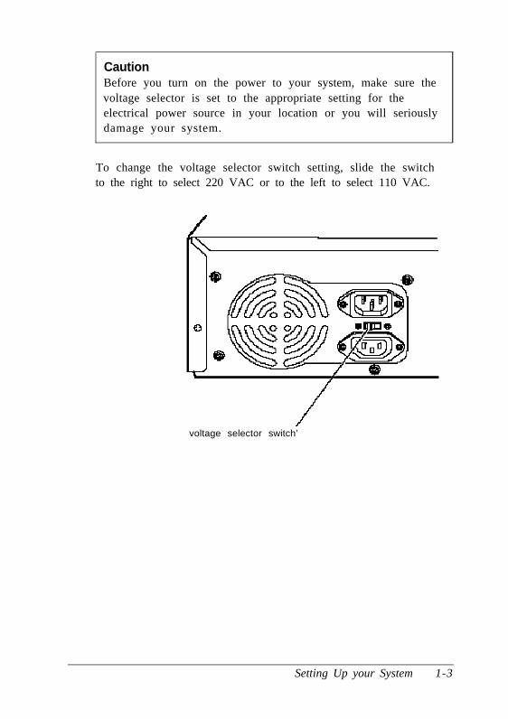
CautionBefore you turn on the power to your system, make sure thevoltage selector is set to the appropriate setting for theelectrical power source in your location or you will seriouslydamage your system.
To change the voltage selector switch setting, slide the switchto the right to select 220 VAC or to the left to select 110 VAC.
voltage selector switch’
Setting Up your System 1-3

Connecting System ComponentsUse the following illustration to locate the ports on the back ofyour system as you connect the keyboard, monitor, printer, andother devices.
/ c \-
powerinlet
CautionAlthough the connectors and ports for the mouse andkeyboard are physically identical, they cannot be usedinterchangeably. Be sure to plug the mouse connector intothe MOUSE port, or you may damage your system.
Your computer also includes two removable panels above themouse and keyboard ports providing access to a game port onthe main system board and to one on an option card, if youinstalled one. You can enable the main system board game portvia a jumper; see Chapter 3.
1-4 Setting Up your System

Connecting the Power CordFollow these steps to connect the power cord:
1. Plug the power cord into the power inlet on the back panelof the computer.
WARNINGTo avoid an electric shock, be sure to plug the cord intothe computer before plugging it into the wall outlet.
2. Plug the other end of the power cord into an appropriategrounded electrical outlet.
After you connect the components of your system, you areready to turn on the power.
Turning Your System On and OffBefore you turn on your system, be sure to read the ImportantSafety Instructions at the beginning of this manual.
CautionIf there is a protective card in a diskette drive, remove it nowor you may damage your drive.
First turn on the monitor, printer, and any other externaldevices connected to the computer.
Setting Up your System 1-5

Then turn on the computer by pressing the power buttonlocated on the right side of the front panel, as shown below.
“-rd diskspeed light ,,ap o w e r l i g h t - -hard diskor reset
Idticesslight diskette drive button
I bays I
&.I.~1---qFY+
IIIIIIIIIIIIIIIIIIIIIIII
T qdiskette drive
The power indicator lights up. After a few seconds, thecomputer performs its power-on diagnostics. This is a series of
everything is working correctly.
If necessary, use the controls on your monitor to adjust the
on the screen.
Whenever you turn off your system, be sure to save your data
the hard disk drive light and the diskette drive light(s) to makesure they are not on. Press the power button to turn off the
peripheral devices.
Now follow the instructions below to configure your system
1-6

Running the SETUP ProgramBe sure to run SETUP the first time you use your computer, soyou can verify or update the configuration information. Youalso may need to run SETUP again later if you change yourconfiguration.
SETUP lets you verify or change the following:
0 System settings such as date, time, diskette drive type(s),and video display type
0 Automatic or manual selection of hard disk drive(s)
0 Automatic or manual selection of advanced hardwarefeatures for optimizing system performance
0 System booting options
0 Password security and anti-virus features
0 Green PC options, such as the time intervals before thesystem and the hard disk drive go into low-power standbymode.
SETUP also allows you to see summary information about yoursystem.
The SETUP program and the factory default settings are storedin the computer’s ROM BIOS (read-only memory, basicinput/ output system). The configuration information you enteris stored in an area of memory called CMOS RAM. Thismemory is backed up by a battery, so it is not erased when youturn off or reset the computer.
Setting Up your System 1-7

Starting the SETUP Program
When you start your computer, it performs some power-ondiagnostics. During these diagnostics, you may see thefollowing message:
P r e s s < F 2 > t o e n t e r S E T U P
(In SETUP, you can disable this message, if desired.)
Press F2 to run SETUP. This message is only on the screen for afew seconds. If you missed it, restart the computer and tryagain.
If the system detects an error in your configuration, you heartwo beeps and see an error message followed by this message:
P r e s s < F 1 > t o r e s u m e , < F 2 > t o S e t u p
Press F2 to run SETUP.
SETUP displays the Main Menu. From this menu, you canselect the various options to identify your system’sconfiguration and then save your new values to CMOS. If youchange your mind, you can cancel any changes you have madeand restore the default values stored in ROM or load the valuespreviously stored in CMOS.
The table below lists the keys you can use to perform SETUPoperations.
SETUP function keys
Key Function
f&t + Move the cursor to the next or previous modifiable option
Home End Move the cursor to the top or bottom of the menu
F1 or Alt H Displays a help screen describing the option currentlyselected
1 - 8 Setting Up your System

SETUP function keys (continued)
Key Function
F5 or-
F6 or + or
Spacebar
F9
Selects the previousvalue
Selects the next value
Loads the factory default values for the SETUP options onthe current Screen
F10 Ignoresany changesyou have made on the currentScreen
Enter Selects the current option or value
Esc or Alt X Returnsto the previousscreen
Whenever you are in SETUP, the bottom of the screen lists thekeys you can press to perform specific functions.
The System Setup Option
From the System Setup screen, you can set the optionsdescribed below.
Setting the time and date
The real-time clock in your computer continuously tracks thedate and time-even when the computer is turned off. Onceyou set the System Time and System Date options, youshould not need to change them, unless you adjust the time fordaylight savings or a different time zone. (The computerautomatically changes the date for leap years.)
Setting the video display type
The Video Systemoption allows you to define the type ofdisplay adapter you are using. If you connected your monitorto the computer’s built-in VGA port, select EGA/VGA.
Setting Up your System 1-9
If you connected a monitor that doesn’t support VGA to avideo adapter card installed in your system, select either theCGA 80 X 25 or the Monochrome option. Also make sureyou disabled the on board VGA controller by setting jumpersJ14 and J15 to the Off position. (See Chapter 3 for instructions.)
Checking system memory
When you boot your system, the system BIOS detects the totalmemory size automatically. You see the memory configurationdisplayed in the System Memory and Extended Memoryfields on this SETUP screen.
You cannot change these values; if they are not what youexpect them to be, check that the SIMM(s) are securely seatedin their sockets. (See Chapter 3 to locate the SIMM sockets.)
Setting the diskette drive type(s)
On your system, diskette drive A is the 3.5-inch high-densitydrive installed in your computer. You may also have anotherdrive of a different size or capacity; this is drive B. Check thesettings for both drives and correct them if necessary.
The Fixed Disk Setup Option
The options on the Fixed Disk Setup screen define the types ofhard disk drives you installed in your system. From this screen,s e l e c t F i x e d D i s k 0 C o n t r o l o r F i x e d D i s k 1C o n t r o l .
Your computer comes with a hard disk auto-sensing feature.Press Enter when the Autotype Fixed Disk option ishighlighted. The system detects the type of hard disk drive andfills in the remaining fields on the screen.
1-10 Setting Up your System

If you are using an older drive or a preformatted drive, it maynot support the auto-sensing feature. If you press Enter whenthe Autotype Fixed Disk option is highlighted and thedrive parameters do not match your drive, check Appendix Ato see if your drive’s parameters are included in the hard diskdrive table. If not, you need to define your own drive type orreformat the disk. See the next section for instructions on howto define your own drive type.
Defining your own drive type
If the parameters for your hard disk do not match theparameters detected by the auto-sensing feature, or if you wantto use your drive with parameters other than the defaults, youcan define your own type. To define your own drive type,follow these steps:
1. Move the cursor to Type and select User.
2. Type the values in each field that are appropriate for yourhard disk drive.
3. When you exit SETUP, make sure you save your changes.
The Advanced System Setup Option
When you select this option from the Main Menu, you see theAdvanced System Setup screen, which contains the optionsdescribed below.
Your system can automatically configure the AdvancedSystem Setup options for you. To avoid configurationproblems, you should let the system configure these options.However, if you connected a scanner or a parallel port networkadapter to your parallel port, be sure to select AdvancedChipset Control so you can change the operation of theparallel port to PS2 mode (for bidirectional operation). Seepage 1-13 for more information.
Setting Up your System 1-11

Configuring cache memory
The system can configure your Memory Cache options or youcan manually set them. If you installed external cache, enablingcache memory improves system performance, especially inlarge data retrieval and processing environments.
If you choose to configure the cache memory yourself (ratherthan let the system configure it for you), you can define thewrite and burst wait states and two non-cacheable areas ofmemory. However, it’s a good idea to let the systemautomatically configure these features.
Configuring memory shadow
The system can configure the Memory Shadow options or youcan manually set them. You can enable or disable shadowing ofyour system and video memory and control the specific blocksof ROM used for this purpose.
Your computer can access RAM faster than ROM. The optionson this screen allow your system to copy the contents of itssystem and/ or video ROM into RAM. When you useshadowing, your system can perform certain operations faster,providing a significant increase in performance.
NoteFor the best system performance, always set the Systemshadow and the Video shadow options to Enabled.
If you enable shadowing for specific blocks, the ROM located inthese blocks is copied to the shadow area.
1-12 Setting Up your System
Configuring chipset registers
The system can set your Advanced Chipset Controloptions or you can manually change the values in the chipsetregisters. Setting these values correctly increases your systemperformance; however, setting them incorrectly may causeyour system to malfunction or shut down. Be sure to set theAuto Configuration option to Enabled to let the systemautomatically configure these options to avoid problems.
However, if you connected a scanner or a parallel port networkadapter to your parallel port, you should set AutoConfiguration to Disabled so you can change thePr in te r Por t Con t ro l op t ion to PS2 mode ( fo rbidirectional operation). The default setting for the parallel portis AT mode (for unidirectional operation).
Setting the Boot Options
When you select Boot Options from the Main Menu, you seethe Boot Options screen, which contains the options describedbelow.
Selecting the drive boot sequence
The Disk d r ive boo t sequence op t ion de te rmines theorder in which the computer checks the drives when it looksfor the operating system.
If you select A: then C:, each time you turn on thecomputer, it first tries to load the operating system from driveA. If drive A doesn’t contain an operating system, thecomputer loads it from drive C. If you select C : then A: , thecomputer tries to load the operating system from drive C first.If drive C doesn’t contain an operating system, the computertries to load it from drive A. If you select C: only, thecomputer tries to load the operating system from drive C only.
Setting Up your System 1-13

Setting the floppy seek option
If you set the Disk drive boot sequence option toC: only, you can disable the Floppy seek option so thesystem does not try to access the diskette drive at startup.Disabling the Floppy seek option decreases the time neededto boot the system.
Disabling the SETUP prompt
The Display SETUP prompt during POST option allowsyou to disable the message Press <F2> to enter SETUPthat you see during power-on diagnostics. You may want todisable this prompt to prevent unauthorized users from seeingthe SETUP prompt. Even when the message is disabled,however, you can still start SETUP by pressing F2 within theallowed amount of time.
Disabling power-on diagnostic error messages
The Pause on POST errors option allows you to disablethe error message and the message Press <F1> tor e s u m e , <F2> to Setup that you see when the systemidentifies a configuration error. If you disable this option, thesystem ignores configuration errors it finds during power-ondiagnostics and starts as it normally would. It’s a good idea tokeep this option enabled.
Disabling the system summary screen
By d isab l ing the Sys tem summary screen a t bootoption, you can disable the system summary screen that yousee when you start the system. If you disable this option, yoursystem starts up faster. You can see the same screen byselecting the System Summary option from the Main Menu.(See page 1-19.)
1-14 Setting Up your System

The System Security and Anti-Virus Options
When you se lec t the Secur i ty and Ant i -Vi rus op t ionfrom the Main Menu, you see the System Security andAnti-Virus screen, which contains the options described below.
Entering or changing a password
You can define both User and Supervisor password levels forthis system. If the system will be used by more than oneperson, you may want to set a Supervisor password foryourself and a User password for others you don’t want tohave complete access to the system. For instance, you maywant to restrict access to the diskette drives or the computer’svirus protection features.
If you enable the Password on boot option, you must enterthe Supervisor or User password each time you turn on thesystem. If you do not enable this option but you have definedpasswords, you must enter the password each time you startthe SETUP program. If both a Supervisor and User passwordare enabled, SETUP displays options for setting the Userpassword only for users who logged on with a user password.
To specify a User password, you must first specify a Supervisorpassword. Follow these steps to enter or change a Supervisorpassword:
1. Select the Set Supervisor Password option and pressEnter.
2. You see a Set Supervisor Password window. Type thepassword you want to use, then press Enter. You can definea password of up to eight characters.
3. Type the same password a second time and press Enter.You see a message that your changes have been saved.
Setting Up your System 1 - 1 5

4 . P res s t he spaceba r . The Supe rv i so r Password I S op t ionis now set to Enabled.
To set a User password, select the Set User Passwordoption and follow the steps above.
Deleting passwords
To delete your passwords, follow these steps:
1. Set the Password on boot option to Disabled.
2. Delete the User password by pressing Enter for both thepassword field and the confirmation field. Don’t type anycharacters in these fields.
3. Then delete the Supervisor password the same way.
NoteYou must delete the User password before SETUP will allowyou to access the Supervisor password.
If you have forgotten your password(s), see “PasswordProblems” in Chapter 5.
Using the virus protection features
Several options on the Security and Anti-Virus screen allowyou to define system protection features.
The Diskette Access option allows you to restrict accessto your diskette drives based on the password levels you havedefined. This prevents unauthorized users from accessing thedrives and possibly introducing a virus to your system. Youcan restrict diskette access only if passwords are enabled andyou have enabled the Password on boot option.
1-16 Setting Up your System

If you select Supervisor for this option, you can access thediskette drives only if you enter the Supervisor password whenyou start your system. Someone who starts the system with a
she tries to access the diskette drive. If you select User forthe Diskette Access option, you can access the diskette
NoteTo use passwords for diskette drive access, you must enablethe Password on boot option. If you select a passwordleve l fo r Diske t t e Access bu t l eave the Password onboot option disabled, you see an error message wheneveryou try to access your diskette drive.
You can also protect your system by selecting Writep r o t e c t f o r t h e F i x e d d i s k b o o t s e c t o r o p t i o n .When this option is enabled, the system displays an errormessage when a program tries to write to the boot sector ofyour hard disk drive. To use a legitimate program (such as theMS-DOS@ FORMAT command) you must disable the writeprotect option.
Two additional options on this screen allow you to define timeintervals for the system to display a prompt asking whetheryou have performed your scheduled virus check or yourscheduled backup for your hard disk drive. You can disablethese prompts or have them display Daily, Weekly, orMonthly. If you respond that you have not performed thesefunctions, however, the system still starts normally.
Setting Up your System 1-17

Using the Green PC Features
The Green PC options allow you to define how theenergy-saving features of this Energy Star compliant systemwill work for you. The options on the Green PC Features screenallow you to disable the energy-saving feature or set time-outperiods to put the system and hard disk drive in a low-energystandby mode.
The Inactivity Timer 1 option sets the t ime-out periodfor video signals to your monitor. When the mouse orkeyboard has been inactive for the time period you select here,your computer stops sending video signals to your monitor. Ifyour monitor is also Energy Star compliant, it goes into alow-power standby mode because it isn’t receiving videosignals from your computer. Screens on monitors that aren’tEnergy Star compliant will go blank when your system is instandby mode.
If you select a time period for the Lockout Timer as well asthe Inactivity Timer 1 option, the system won’t acceptyour keyboard input for the specified period of time after yoursystem has returned to an active mode. This allows time foryour monitor to return to full power also.
The Fixed Disk Timeout option determines the t ime-outperiod for your hard disk drive. The hard disk drive goes into alow-power standby mode when the mouse and keyboard havebeen inactive for the period of time you’ve indicated.
NoteSome hard disk drives do not support a low-power standbymode. Also, the delay caused by the hard disk drivereturning to active mode may cause errors in someapplications. If you have problems, you may want to disablet h e F i x e d D i s k T i m e o u t o p t i o n .
1 - 1 8 Setting Up your System

The System Summary Option
When you select the System Summary option from the MainMenu, the SETUP program displays a summary of theconfiguration settings for your system.
This is the same screen you see during system startup. You canchoose not to have the system display this screen so systemstartup is faster. See page 1-14 for information on disabling thisop t ion
Exiting SETUP
When you leave SETUP, you can save your settings, or exitSETUP without saving your settings. You can also return allvalues to the factory defaults.
To leave SETUP, press ESC from any SETUP screen. From theMain Menu, you can do the following:
Load ROMDefault Values
Loads the factory default settingss t o r e d i n R O M b a c k i n t oCMOS.I f y o u c h a n g e y o u r s y s t e mc o n f i g u r a t i o n a n d t h e nh a v e p r o b l e m s , y o u c a nl o a d t h e R O M v a l u e s t ob o o t t h e s y s t e m a n d s t a r to v e r .
Load Valuesfrom CMOS
Loads the current values stored inCMOS for all SETUP options. Thisignores any changes you havemade using SETUP.
Save Values to Saves the configuration changesCMOS you have made to CMOS.
Setting Up your System 1 - 1 9

Post-SETUP Procedures
After you run SETUP for the first time, you may need to installthe operating system if your computer is not preconfigured.See your operating system manual for instructions.
Once you have installed your operating system, install anysoftware you plan to use. See your application programmanuals for instructions.
You may also want to install the optional extended videodrivers for some of your application programs. (If yourcomputer was configured for you, these drivers are alreadyinstalled.) The README files on Drivers Diskettes 1 and 2provide instructions for installing and using the drivers.
To read the file on your screen, insert Drivers Diskette 1 indrive A, type the following, and press Enter:
A:\README
To print the file to your printer, type the following and pressEnter:
A:\READMEP
Use the same commands to read or print the README file onDrivers Diskette 2.
NoteIf you plan to install video drivers for Microsoft® WindowsTM
applications, you must install Windows before you installthe drivers.
1-20 Setting Up your System

Chapter 2
Using Your Computer
This chapter briefly describes the following operations:
0 Working comfortably
0 Stopping a command or program
0 Resetting the computer
0 Using energy wisely
0 Using the Green PC features
0 Changing the processor speed
Working ComfortablyThis section provides some tips for creating a comfortable workenvironment.
0 Use good posture. Keep your elbows, hips, and knees bentat approximately 90 degree angles and keep your wrists asclose to horizontal as possible.
0 Vary your posture often and take frequent breaks. Standup, stretch, and move around.
0 Use a good chair. Make sure your chair supports yourlower back. A chair with padded armrests lets you restyour arms as you work.
Using your Computer 2-1

If you use a copy stand, keep it at the same eye level asyour screen. This reduces eye and neck strain. Also, restyour eyes occasionally by closing them or focusing on afixed spot in the distance.
Be gentle with your keyboard. Too much force createstension in your hands. Also, make sure your work surfacehas enough room for you to move the mouse or otherpointing device freely.
Use good lighting that isn’t too bright. Try to keep brightlight sources out of your field of vision when you arelooking at the screen.
Place your monitor directly in front of you and sit about anarm’s length away from it. The top of the screen should beslightly below your eye level so you look down at thescreen. Position the monitor so that no light is reflectedfrom the screen.
Stopping a Command or ProgramYou may sometimes need to stop a command or program whileit is running. If you have entered an MS-DOS or applicationprogram command that you want to stop, try one of thefollowing:
0 Press Pause
0 Press Ctrl C
0 Press Ctrl Break.
If these methods do not work, you may need to reset thecomputer as described below. Do not turn off the computer toexit a program or stop a command unless you have to, becausethe computer erases any data you did not save.
2-2 Using Your Computer

Resetting the ComputerOccasionally, you may want to clear the computer’s memorywithout turning it off. You can do this by resetting thecomputer.
For example, if an error occurs and the computer does notrespond to your keyboard entries, you can reset it to reloadyour operating system and try again. However, resetting erasesany data in memory that you have not saved, so reset only ifnecessary.
CautionDo not reset the computer to exit a program. Some programsclassify and store new data when you exit them normally. Ifyou reset the computer without properly exiting a program,you may lose data.
Also do not remove a diskette or reset or turn off thecomputer while a diskette drive light is on. You could losedata. Be sure to remove all diskettes before you turn off thecomputer.
To reset the computer, press Ctrl Alt Del. The screen displaysnothing for a moment and then the computer reloads youroperating system.
You can also press the RESET button located in the upper rightcorner on the front of your computer.
If resetting the computer does not correct the problem, youprobably need to turn it off and on again. Remove anydiskette(s) from the diskette drive(s). Turn off the computerand wait 20 seconds. If you do not have a hard disk, insert thesystem diskette in drive A. Then turn on the computer.
Using your Computer 2-3

Using Energy WiselyBy purchasing this low-power, Energy Star compliantcomputer, you join a growing number of users concerned aboutconserving energy. Here are a few additional tips you can useto be even more energy-wise:
0 If your printer and monitor aren’t Energy Star compliant,turn them off when you’re not using them.
0 Use your software’s print preview option (if available)before you print something. You’ll be able to catchformatting errors before you commit them to paper.
0 If you have an electronic mail system available to you, sendE-mail rather than memos. Not only is this faster, but you’llsave paper and storage space too.
0 Use recycled paper whenever you can
Using Your Green PC FeaturesYour computer places the system, the hard disk drive, or bothinto a low-power standby mode when the keyboard or mousehas been inactive for the time periods you select in SETUP. SeeChapter 1 for information on setting these values.
When your system is in standby mode, the Num Lock light onyour keyboard flashes and your screen is blank. Press any keyor move the mouse to resume activity.
If the hard disk drive is in standby mode, it doesn’t return toactive mode until you access it. You’ll hear it start again. It willtake a second or two to reach its operating speed and read orwrite to the disk. The hard disk drive access light turns onwhen the system begins accessing the disk.
2-4 Using Your Computer

NoteSome hard disk drives do not support a low-power standbymode. Also, the delay caused by the hard disk drivereturning to active mode may cause errors in someapplications. If you have problems, you may want to disablethe standby mode for the hard disk drive.
Changing the Processor SpeedYour computer’s processor can operate at two speeds: fast orslow (8 MHz). The slow speed is available to providecompatibility with older application programs, such as thosethat require you to leave a key disk-the diskette that containsthe copy protection-in the diskette drive.
When your computer is operating at fast speed, the SPEED lighton the front panel is on. When the computer is operating atslow speed, the light is off.
You should use fast speed for almost everything you dobecause your programs will work faster. However, certainapplication programs have specific timing requirements andcan run only at the slower speed. See your application softwaremanual to determine if this is the case.
You can change the processor speed temporarily by enteringone of the following commands from the numeric keypad onyour keyboard :
0 To select slow speed, press Ctrl Alt --. (Press the --key on thenumeric keypad.)
0 To select fast speed, press Ctrl Alt +.
The speed setting remains in effect until you reset yourcomputer or turn it off.
Using your Computer 2-5

NoteYou can use the commands listed above while you arerunning a program. However, if the program uses one ofthese commands for another function, you cannot use it tochange the processor speed.
2-6 Using Your Computer

Chapter 3
InstaIling and Removing Options
You can enhance the performance of your computer by addingoptional equipment such as memory modules, option cards,video memory, cache memory, or a new microprocessor.
This chapter first describes how to remove your computer’scover to install options and how to replace the cover when youare finished. It then describes the following:
0 Locating the internal components
0 Changing the jumper settings
0 Installing and removing memory modules
0 Installing and removing option cards
0 Adding video memory
0 Adding cache memory
0 Upgrading the microprocessor.
CautionNever install options or change jumper settings with thecomputer turned on or the power cord connected to thecomputer.
Once you have installed your option, see “Post-installationProcedures” on page 3-26.
Installing and Removing Options 3-1

Removing the CoverYou need to remove the computer’s cover to install any of theoptions described in this chapter or to install or remove a diskdrive (described in Chapter 4). Follow these steps to removethe cover:
1. Turn off the computer and then any external devices
2. Disconnect the computer’s power cable from the electricaloutlet and from the back panel. Also disconnect any cablesthat are connected to the computer, including the keyboardcable.
3. If the monitor is on top of the computer, lift it off and set it toone side.
4. Turn the computer around so the back panel is facing you.
5. Remove the three screws securing the cover to the back panel,as shown below.
3-2 Installing and Removing Options

6. Grasping the sides of the cover, lift it up at an angle and pullit off, as shown below.
7. Set the cover aside.
8. Ground yourself to the computer by touching the metalsurface of the back panel.
WARNINGBe sure to ground yourself by touching the back panel of thecomputer every time you remove the cover. If you are notproperly grounded, you could generate an electric shockthat could damage a component when you touch it.
Installing and Removing Options 3-3

Replacing the CoverWhen you are ready to replace the computer’s cover, followthese steps:
1. Make sure all the internal components are installed properly.
2. Check all cable connections, especially those that might havebeen loosened during your work.
3. Make sure all cables are out of the way so they do not catchon the cover.
4. Insert the lip at the front of the cover between the front bezeland the computer case and guide it straight down. (See theillustration on page 3-3.)
5. Replace the three cover retaining screws.
6. Reconnect the computer to the monitor, printer, keyboard,and any other peripheral devices you have. Then reconnectthe power cable to the back of the computer and to anelectrical outlet.
3-4 Installing and Removing Options

Locating the Internal ComponentsAs you follow the instructions in this chapter, refer to thefollowing illustration to locate the major components on yoursystem board.
externalrc..rkn
sot kl
microprocessor J15
\
J2:J2LJ2EJ2E
hard disdriveconnec
J33
k
tor
J31 ’
J17 /
option cac o n n e c tboard
rdI
or
J30 ._
videoJ14 J13 Jll
/ /memory
r
//
II
\‘ keyboard
Pod
J4
/SlMMsockets
Idiskettedrive
.iD J5
JE J6J7
connector J8JAJBJC
Installing and Removing Options 3-5
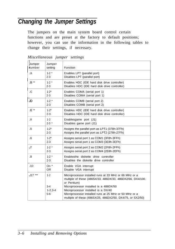
Changing the Jumper SettingsThe jumpers on the main system board control certainfunctions and are preset at the factory to default positions;however, you can use the information in the following tables tochange their settings, if necessary.
Ict
Miscellaneous jumper settings
Jumper Jumperlumber setting Function
JA 1-2 * Enables LPT (parallel port)2-3 Disables LPT (parallel port)
JB ** 1-2 * Enables HDC (IDE hard disk drive controller)2-3 Disables HDC (IDE hard disk drive controller)
JC 1-2* Enables COMA (serial port 1)2-3 Disables COMA (serial port 1)
JD 1-2 * Enables COMB (serial port 2)2-3 Disables COMB (serial port 2)
JE ** 1-2* Enables HDC (IDE hard disk drive controller)2-3 Disables HDC (IDE hard disk drive controller)
J4 1-2 Enablesgame port (J1)2-3 * Disables game port (J1)
J5 1-2* Assigns the parallel port as LPT1 (378h-37Fh)2-3 Assigns the parallel port as LPT2 (278h-27Fh)
J6 1-2* Assigns serial port 1 as COM1 (3F8h-3FFh)2-3 Assigns serial port 1 as COM3 (3E8h-3EFh)
J7 1-2 * Assigns serial port 2 as COM2 (2F8h-2FFh)2-3 Assigns serial port 2 as COM4 (2E8h-2EFh)
J8 1-2 * Enablesthe diskette drive controller2-3 Disables the diskette drive controller
J10 On * Enable VGA interruptOff Disable VGA interrupt
J17 *** 1-2 Microprocessor installed runs at 33 MHz or 66 MHz or amultiple of these (486SX/33, 486DX/33, 486DX2/66, DX4/100,or Pentium)
3-4 Microprocessor installed is a 486DX/501-2,3-4 Microprocessor installed is a DX/405-6 Microprocessor installed runs at 25 MHz or 50 MHz or a
multiple of these (486SX/25, 486DX2/50, DX4/75, or SX2/50)
3-6 Installing and Removing Options
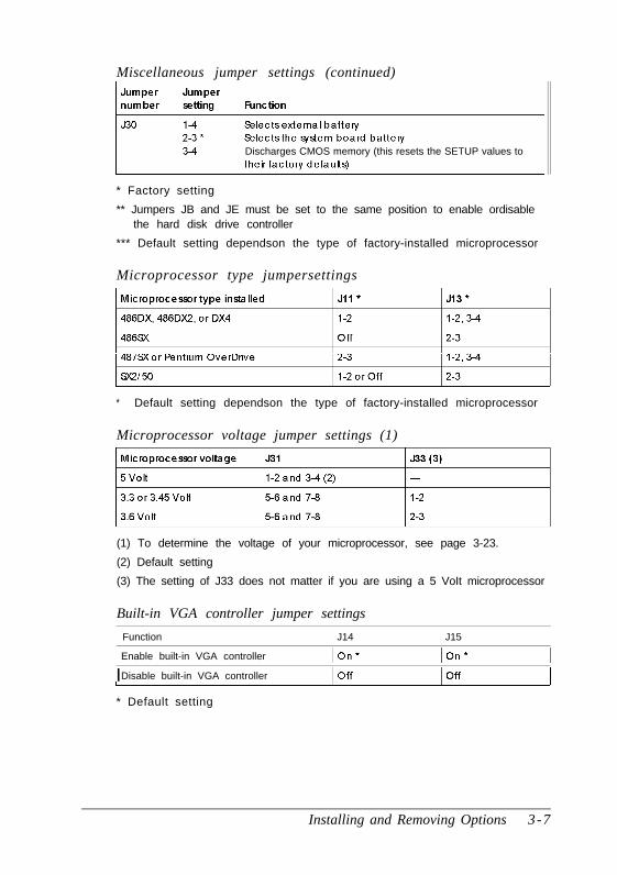
Miscellaneous jumper settings (continued)
Discharges CMOS memory (this resets the SETUP values to
* Factory setting
** Jumpers JB and JE must be set to the same position to enable ordisablethe hard disk drive controller
*** Default setting dependson the type of factory-installed microprocessor
Microprocessor type jumpersettings
* Default setting dependson the type of factory-installed microprocessor
Microprocessor voltage jumper settings (1)
(1) To determine the voltage of your microprocessor, see page 3-23.
(2) Default setting
(3) The setting of J33 does not matter if you are using a 5 VoIt microprocessor
Built-in VGA controller jumper settings
Function J14 J15
Enable built-in VGA controller
IDisable built-in VGA controller
* Default setting
Installing and Removing Options 3-7

NoteTo use an external display adapter in an expansion slot, youmust disable the built-in VGA adapter.
External cache size jumpersettings
7,tI
I
J25 1 J26
Off 1 2-3
1-2 I 1-2
2-3 1 2-3
* If you have no externalcache, the setting of these jumpers does notmatter
The jumpers listed in the preceding tables are the only onesyou may need to change; others are for service purposes only.
Setting the Jumpers
If you need to change any jumper settings, follow these steps:
1. Refer to the illustration on page 3-5 to locate the jumpers.
2. If the jumper you need to change is blocked by any optioncards installed in your computer, you need to remove thecard(s) to access the jumpers. See page 3-17.
3. To move a jumper from one position to the other, useneedle-nose pliers or tweezers to pull it off its pins andgently move it to the desired position.
CautionBe careful not to bend the jumper pins or damage anysurrounding components on the main system board.
3-8 Installing and Removing Options

4. Replace any option cards you removed; see page 3-14.
Installing Memory ModulesYour computer comes with 4MB or 8MB of memory onmemory modules-also called SIMMs (single in line memorymodules). By installing additional SIMMs, you can increase theamount of memory in your computer up to 64MB.
There are two SIMM sockets on the main system board, andeach can contain one SIMM. You can use 1MB, 2MB, 4MB,8MB, 16MB, and 32MB SIMMs.
The following table shows the possible SIMM configurations;do not install memory in any other configuration. The labels onthe system board identify the sockets (Bank 0 and Bank 1) whereyou should install SIMMs.
SIMM configurations
Bank 0
1MB
1MB
2MB
2MB
1MB
4MB
4MB
4MB
4MB
8MB
8MB
Bank 1 Total memory
- 1MB
1MB 2MB
- 2MB
1MB 3MB
2MB 3MB
- 4MB
1MB 5MB
2MB 6MB
4MB 8MB
- 8MB
1MB 9MB
Installing and Removing Options 3-9

SIMM configurations (continued)
Before you install SIMMs, check the following guidelines toensure that they will work properly:
0 Use only tin-plated, 72-pin, 32-bit or 36-bit, fast-page modeSIMMs that operate at an access speed of 80ns(nanoseconds) or faster. Be sure all the SIMMs operate atthe same speed.
0 Use the correct SIMM configuration to add the amount ofmemory you want. See the table above.
3-10 Installing and Removing Options

0 Your SIMM sockets may not look exactly like the ones inthe illustrations. If you’re not sure how to install SIMMs,contact the EPSON Connection and ask for assistance.
Inserting SIMMs
Follow these steps to install SIMMs:
1. Refer to the illustration on page 3-5 to locate the SIMMsockets.
2. Remove any option cards that may be blocking your accessto the SIMM sockets. (See page 3-17 for instructions.)
3. Position the first SIMM at an angle over the first emptysocket in the bank you are filling, as shown below. Thecomponents on the SIMM should face the computer’spower supply.
Installing and Removing Options 3 - 1 1

4. Push the SIMM into the socket until it is seated firmly in theslot. Then tilt it upright, as shown below, guiding the holeat each end of the SIMM over the retaining post at each endof the SIMM socket. If it does not go in smoothly, do notforce it; pull it all the way out and try again.
5. Repeat steps 3 and 4 for the other SIMM, if necessary.
6. Replace any option cards you removed. (See page 3-14 forinstructions.)
Removing SIMMs
If you need to remove SIMMs from your computer (to installdifferent ones, for example), follow the steps below:
1. Remove any option cards that may be blocking your accessto the SIMM sockets. (See page 3-17 for instructions.)
3-12 Installing and Removing Options

2. Use your fingers or a small screwdriver to carefully pullaway the tabs that secure the SIMM at each end, as shownbelow. As you pull away the tabs, the SIMM falls to theside. Remove it from the socket.
3. If necessary, follow the same procedure to remove the otherSIMM.
4. Replace any option cards you removed, as described in thenext section.
Installing and Removing Options 3 - 1 3

Installing an Option CardThis section explains how to install option cards in yourcomputer. Your computer has five 16-bit, ISA slots: three full-length and two half-length.
As you install option cards, keep these guidelines in mind:
0 Check the components on your card and the system boardbefore deciding which slot to use. Make sure that nocomponents are touching or obstructing other cards orcables.
0 When you unpack the option card, do not touch any of thecomponents on the circuit board or the gold-edgedconnectors. Place it gently on top of its original packingmaterial with the component side facing up. Keep thepacking materials in case you remove the card later.
0 Before you install the card, adjust any switches or jumperson it, if necessary. (See the instructions that came with thecard.) Also, see if you need to change any jumper settingson the system board. (For example, if you install a videocard, you need to disable the built-in VGA adapter.) Seepage 3-6 for more information on jumpers.
3-14 Installing and Removing Options

Installing a Card in a Full-length Slot
Follow these steps to install an option card in one of thefull-length slots:
1. Remove the retaining screw securing the option slot coverto the computer, as shown below. (Keep the screw to securethe option card to the computer.)
2. Slide out the slot cover and set it aside. (Store it in a safeplace in case you remove the option card later.)
3. Hold the card along the top corners and guide it into theslot, as shown below. (If you are installing a full-lengthcard, insert the front edge of the card into thecorresponding guide inside the computer’s front panel.)
Once the connectors reach the slot, push the card in firmly(but carefully) to insert it fully. You should feel it fit intoplace. If the card does not go in smoothly, do not force it;pull it all the way out and try again.
Installing and Removing Options 3 - 1 5

4. Secure the end of the card to the computer with the retainingscrew.
Installing a Card in a Half-length Sot
Follow these instructions to install a card in one of thehalf-length slots:
1. Remove the retaining screw securing the slot cover bracketRemove the bracket by lifting it straight up and out of thesmall meta1 holder at the bottom.
tdot coverbracket
/
2. Remove the slot cover.
3-16 Installing and Removing Options

3. Hold the card along the top corners with the componentsfacing down and guide it into the slot.
Once the connectors reach the slot, push the card in firmly(but carefully) to insert it fully. You should feel the card fitinto place. If it does not go in smoothly, do not force it; pullthe card all the way out and try again.
4. Replace the slot cover bracket by inserting it into the smallmetal holder below the option slots.
5. Secure the slot cover bracket to the computer with theretaining screw.
Removing an Option CardYou may need to remove an option card installed in yourcomputer to access components on the main system board-tochange a jumper setting, for example. You may also want toremove a card if you no longer need it. Refer to the illustrationson pages 3-15 and 3-16 as you follow these steps:
1. If you are removing a card from one of the full-length slots,first remove the retaining screw securing the option card tothe computer. Then pull the card straight out of the slot.
2. If you are removing a card from one of the half-length slots,first remove the slot cover bracket. Then pull the cardstraight out of the slot.
3. Set the card aside with the component side facing up.
4. If you are not installing another option card in the empty slot,replace the option slot cover and retaining screw.
Installing and Removing Options 3 - 1 7

Adding Video MemoryYour computer comes with 512KB or 1MB of video memory. Ifyou have 512KB, you can increase your video memory to 1MBby installing four video DRAM DIP (Dual Inline Package)chips. The chips must be 20-pin, 256KB chips that operate at a70ns access speed. For the memory to work properly, you mustinstall one chip in each empty video RAM socket on the systemboard.
Additional video memory is useful for running graphics-intensive applications or for supporting video resolutions up to1280 x 1024 in 16 colors. See Appendix A for information onsupported colors and resolutions for each amount of videomemory.
The table below lists the video DRAM DIP chips that areapproved for use in your computer.
Video DRAM DIP chip types
Manufacturer Part number
Goldstar GM71C256A-70/80 I
1 Fiji MB81C256A-70/80 I
NMBS AAA1M204P-70/50
Toshiba TC514256AP-7/8 ISamsung KM44C256BP-7/8 I
Note that your video memory sockets may not look exactly likethe ones shown here. If you’re not sure how to install videomemory chips, contact the EPSON Connection and ask forassistance.
3-18 Installing and Removing Options

Locate the video memory sockets on the main system board,shown on page 3-5.
If there is an option card in your way, remove it. See page3-17 for instructions.
CautionTo avoid generating static electricity and damaging thememory chips, ground yourself by touching the metalsurface on the inside of the computer’s back panel. Thenremain as stationary as possible while you install them.
Remove the memory chips from their package and inspecteach one. The pins should point inward at slightly less thana 90° angle. If any of the pins are not in this position, useyour fingers or small tweezers to gently align them with theother pins. Be careful; the pins are fragile and can break offeasily.
Position one of the memory chips over the socket as shownbelow, aligning the pins on the chip with the holes in thesocket. Make sure the small notch on the end of the chipaligns with the corresponding notch in the socket.
notches
Installing and Removing Options 3 - 1 9

Gently press the chip halfway into the socket (to make sureit is correctly aligned). If the chip does not go in smoothly,remove it and try again.
When the chip is properly positioned, push down firmly onboth ends to make sure it is well-seated.
Repeat steps 4 through 6 for each of the remaining chips.
Replace any option cards you removed. See page 3-14 forinstructions.
Installing External CacheYou can install 64KB, 128KB, or 256KB of external cache onyour system.
0 To install 64KB of external cache, use eight SRAM, 28-pin,8K x 8,20ns DIP chips, and one 8K x 8,20ns tag chip
0 To install 128KB of external cache, use four SRAM, 28-pin,32K x 8,20ns DIP chips, and one 8K x 8,20ns tag chip
0 To install 256KB of external cache, use eight SRAM, 28-pin,32K x 8,20ns DIP chips, and one 32K x 8,20ns tag chip.
The table below lists the cache SRAM DIP chips that areapproved for use in your computer.
Cache SRAM DIP chip types
Manufacturer Part number II Manufacturer Part number
3-20 Installing and Removing Options

For the cache memory to work properly, you must install chipsin the following configuration (each bank contains four cachememory sockets):
Cache memory configurations
Bank 0 Bank 1U23 - U26 U30 - U33
8K x 8 8K x 8
32K x 8 -
32K x 8 32K x 8
Tag SRAMU34
8K x 8
8K x 8
32K x 8
Total cache
64KB
128KB
256KB
Note that your cache memory sockets may not look exactly likethe ones illustrated here. If you’re not sure how to install cachememory chips, contact the EPSON Connection and ask forassistance.
Installing the External Cache Chips
Follow these steps to install the external cache chips:
1. Locate the external cache memory sockets on the main systemboard, shown on page 3-5.
2. If there is an option card in your way, remove it. Seepage 3-17 for instructions.
CautionTo avoid generating static electricity and damaging thecache chips, ground yourself by touching the metalsurface on the inside of the computer’s back panel. Thenremain as stationary as possible while you install them.
Installing and Removing Options 3 - 2 1


9. Replace any option cards you removed. See page 3-14.
10. Run SETUP to enable the External Cache option andcheck tha t the Sys tem shadow and Video shadowoptions are enabled. You select these options from theMemory Cache and Memory Shadow options on theAdvanced System Setup menu. (See Chapter 1.)
Upgrading the MicroprocessorYou can upgrade your computer by replacing themicroprocessor with a faster one. The following table lists themicroprocessors, their voltages, and other components you caninstall in your system.
Microprocessor upgrade components
Part Manufacturer Voltage
486SX/33 processor Intel 5 Volt
486DX/33 processor Intel** or Cyrix* 5 Volt
486DX/40 processor Cyrix * 5 Volt
486DX/50 processor Intel **or Cyrix * 5 Volt
486DX2/50 processor Intel **or Cyrix * 5 Volt
486DX2/66 processor Intel** or Cyrix* Intel, 5 Volt; Cyrix, 5 Volt or3.6 Volt
SX2/50 processor Intel ** 5 Volt
DX4/75 processor Intel** or Cyrix** Intel, 3.45 Volt; Cyrix, 5 Volt
DX4/100 processor Intel** or Cyrix** Intel, 3.3 Volt; Cyrix, 5 Volt
Pentium OverDrive Intel ** 5 Voltprocessor
Heat sink* Tennmax Trading Corp.® -
Heat sink/fan assembly** Tennmax Trading Corp. -
* A heat sink isrequired for all Cyrix DX and DX2 processors (except the
DX/33) and the Intel SX2/50 processor
** A heat sink and fan assembly are required for all Intel DX, DX2, and
Pentium OverDrive processors and for the Inteland Cyrix DX4 processors;
except the Intel DX/33, which does not need a fan assembly
Installing and Removing Options 3-23

Note that your microprocessor socket may not look exactly likethe one illustrated here. If you’re not sure how to install yournew processor, contact the EPSON Connection and ask forassistance.
Replacing the Processor Chip
Follow these steps to replace the processor chip :
1. Use the illustration on page 3-5 to locate the microprocessoron the system board. The microprocessor chip may beinserted in a ZIF (Zero Insertion Force) socket.
CautionMake sure you ground yourself by touching the metalsurface on the inside of the computer’s back panel beforeyou touch the processor chip. Then remain as stationaryas possible while you install it. Do not touch the pins onthe processor chip; handle it only by the edges of its case.
2. If there are any option cards in your way, remove them. Seepage 3-17 for instructions.
3. Open the ZIF socket by lifting up the ZIF handle. The handlerests under a plastic tab. Press the handle down and awayfrom the tab; then rotate the handle upward. This releasesthe chip from the socket. The illustration on the next pageshows this handle in the released position.
4. Gently pull the processor chip straight up and set it aside.
NoteThe 486SX/25 microprocessor may be soldered onto anadapter board that is seated in the socket. Remove theadapter board as described above.
3-24 Installing and Removing Options

5. Remove the replacement chip from its package and inspectthe pins. If they are bent, do not install the processor chip.Contact your vendor for a new microprocessor.
6. Position the processor chip over the socket, aligning thenotched edge of the chip (marked with a dot) with pin 1 onthe socket, as shown below.
dot/
pin 1
CautionIf you install the processor chip in the wrong orientation,you may damage the chip and void your warranty.
7. Make sure the pins in the processor chip are directly over theholes in the socket. Then gently push the microprocessorstraight into the socket, pressing evenly on all sides.
If you are installing a 486 chip rather than a PentiumOverDrive processor, you’ll see an extra row of holesaround the outside of the socket. The 486 chip does notoccupy the outside row of holes.
Installing and Removing Options 3-25
8. Secure the processor chip by pressing the ZIF handle back tothe closed position.
9. Check the settings ofjumpers J11 and J13 to be sure they arecorrect for the type of microprocessor you installed. Youmay also need to change the setting of jumper J17 to matchthe microprocessor type and operating speed.
If you installed a microprocessor with a different voltage(check the table on page 3-23) you need to change thesettings ofjumpers J31 and J33. See pages 3-6 and 3-7 forinformation on all these jumper settings.
10. If you are upgrading to a DX/ 40, DX/ 50, DX2, DX4, SX2, orPentium OverDrive processor, you must install a heat sinkand/or a fan, depending on the brand of processor youinstalled. See the table on page 3-23 for more information.Follow the instructions included with the heat sink if youneed to install one. If the heat sink comes with a fan, installit using the instructions that came with the heat sink andfan kit.
11. If you removed any option cards, replace them now; seepage 3-15 to replace a full-length card or page 3-16 toreplace a half-length card.
12. Run SETUP as described in Chapter 1 to update yourcomputer’s configuration with the new microprocessor
Post-installation ProceduresAfter you install or remove options, you must run SETUP toupdate the computer’s configuration. See Chapter 1 forinstructions. Additionally, you may need to add somecommands to your configuration files. See your operatingsystem manual and the manual that came with your optionalequipment.
3-26 Installing and Removing Options

Chapter 4
Installing and Removing Drives
This chapter describes how to install and remove optionaldrives in your computer. You can use these instructions toinstall a variety of devices, including hard disk, diskette, tape,CD-ROM, and optical drives. Although your drive may lookdifferent from the ones illustrated here, you should be able toinstall it the same way.
Your computer can hold up to four mass storage devices. Youcan install one hard disk drive using the internal mountingbracket below the diskette drive. In the externally accessiblebays, you can install a second diskette drive or another type ofdrive.
To install or remove a drive, first remove the computer’s coveras described in Chapter 3. Then remove any option cards thatmay be in your way. Once you have installed the drive, replaceany option cards you removed. See Chapter 3 for instructions.
Follow the appropriate instructions in this chapter to installand remove drives:
0 Removing the drive mounting bracket
0 Installing a hard disk drive in the mounting bracket
0 Removing a hard disk drive from the mounting bracket
0 Installing a drive in one of the externally accessible drivebays
0 Removing a drive from one of the externally accessibledrive bays
0 Post-installation procedures.
Installing and Removing Drives 4-1

Some of the steps in this chapter may not apply for the driveyou are installing. See the documentation that came with yourdrive for more information.
Removing the Drive Mounting BacketYour computer has a 3.5-inch diskette drive installed in amounting bracket. (You may also have a hard disk driveinstalled in the bracket.) In order to install or remove anydrives in the computer, you must first remove the drivemounting bracket. Follow these steps:
1. Remove the two cables from the diskette drive, as shownbelow. Grasp the connectors and pull them straight out soyou do not bend the pins; do not pull on the cables. (Ifnecessary, remove the cables from the hard disk drive also.)
4-2 Installing and Removing Drives

2. Remove the screws securing the bracket to the drive bay andbrace.
brace
P /
3. Slide the bracket away from the front of the computer and liftit out.
lnstalling a Hard Disk Drive in the MountingBracket
You can install a hard disk drive below the diskette drive in themounting bracket after you have removed the bracket anddrive from the computer. In order to fit in this space, your harddisk drive must be 1 inch high by 3½ inches wide. If you havea larger hard disk drive, you can install it in one of the drivebays (see page 4-15).
Installing and Removing Drives 4-3

This section includes steps for the following procedures:
0 Removing the mounting frames from the hard disk drive(if necessary)
0 Installing the hard disk drive in the mounting bracket
0 Replacing the mounting bracket in the computer
0 Connecting the drive cables.
Be sure to check the jumper settings on the hard disk drivebefore you install it. If you have two hard disk drives, one mustbe configured as the master (which contains the operatingsystem) and the other as the slave. A table of jumper settingsfor high-capacity EPSON drives is included in Appendix A.
Also, you may need to know the number of cylinders, heads,sectors, etc., if the hard disk drive auto-sensing feature inSETUP is unable to correctly identify your drive. The hard diskdrive table used in the SETUP program is included inAppendix A. If your drive is not listed or you need moreinformation, see the documentation that came with your driveor contact the manufacturer.
4-1 Installing and Removing Drives
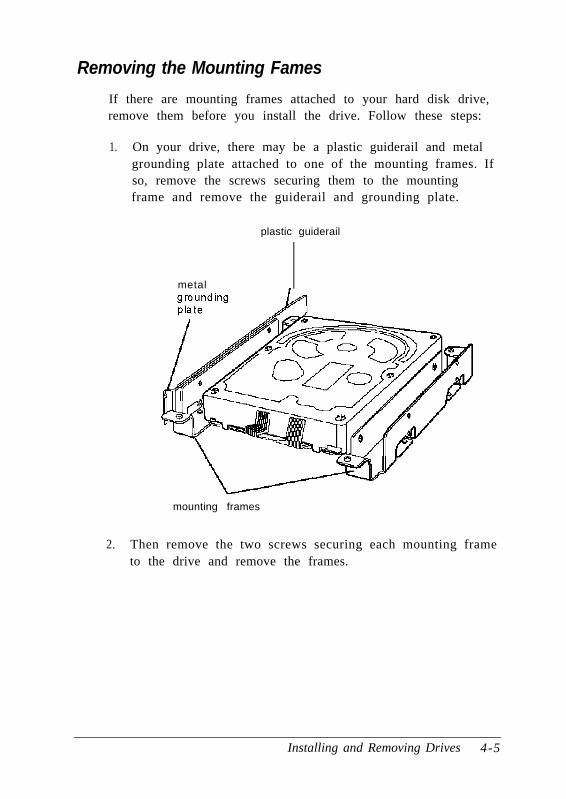
Removing the Mounting Fames
If there are mounting frames attached to your hard disk drive,remove them before you install the drive. Follow these steps:
1. On your drive, there may be a plastic guiderail and metalgrounding plate attached to one of the mounting frames. Ifso, remove the screws securing them to the mountingframe and remove the guiderail and grounding plate.
plastic guiderail
metal
mounting frames
2. Then remove the two screws securing each mounting frameto the drive and remove the frames.
Installing and Removing Drives 4-5

NoteBefore you install the hard disk drive, turn it over so you cansee the circuit board, as shown below. Locate the side of thedrive connector containing pin 1, indicated by a “1” or “2”printed on the board. You will need to know the location ofpin 1 when you connect the hard drive cable.
pin 1
Installing the Hard Disk Drive
Follow these steps to install the hard disk drive in themounting bracket:
1. With the drive components facing down, slide the drive intothe bracket until the front of the drive is nearly flush withthe edge of the bracket.
4-6 Installing and Removing Drives

2. Align the holes in the drive with the oval-shaped holes in thebracket.
3. Secure the drive with two or four screws, depending on thelocation of the holes.
Installing and Removing Drives 4 - 7

Replacing the Bracket in the Computer
Follow these steps to replace the bracket in your computer:
1. Lower the bracket with the drives into the mounting areaand slide it forward, guiding the front of the diskette drivethrough the drive slot in the front panel of the computer.
2. Make sure the holes in the bracket are aligned with the holesin the drive bay and brace. Then secure the bracket with thescrews you removed previously.
4-8 Installing and Removing Drives

Connecting the Drive Cables
After you replace the bracket, you need to connect the cablesfor both the hard disk drive and the diskette drive. This sectionincludes steps for the following procedures:
0 Connecting the drive ribbon cable to the system board
0 Connecting the cables to the hard disk drive
0 Reconnecting the cables to the diskette drive.
Connecting the drive cable to the system board
Follow the steps below to connect the hard drive ribbon cableto the system board, if it is not already connected.
1. Locate the hard disk drive ribbon cable; it is a flat cable withthree connectors that came in the box with your computer.All the connectors on this cable look the same.
system board connector for second connector for firstconnector hard disk drive hard disk drive
red wire
Installing and Removing Drives 4-9

2. Locate the hard disk drive connector on the system boardusing the illustration below.
3. Position the system board connector end of the cable so thatthe red wire aligns with pin 1 of the connector on thesystem board. There is a “1” printed on the system board toidentify pin 1.
pin 1
4. Make sure the holes in the connector fit over the pins; thenpush in the cable connector.
CautionIf you do not correctly align the holes with the pins, youcould severely damage your system board when you pushin the cable connector.
4-10 Installing and Removing Drives

Connecting the ribbon and power cables to the drive
Follow the steps below to connect the hard disk drive ribboncable and a power supply cable to the drive:
1. Locate the hard disk drive connector on the end of the harddisk drive ribbon cable.
2. Locate pin 1 on the drive connector. If you do not see it onthe connector casing and you did not locate it before youreplaced the drive bracket, you may have to remove thedrive and turn it over to check the circuit board. See page4-14 for instructions on removing the drive and page 4-6 forinstructions on locating pin 1 on the drive connector.
3. Position the connector on the cable so that the red wirealigns with pin 1 on the drive.
Installing and Removing Drives 4-11

4. Make sure the holes in the cable connector fit over all thepins; then push in the connector.
5. Locate one of the power supply cables that lead from thepower supply. (They have multi-colored wires and a plasticconnector on the end.)
6. Position the power supply cable connector so that itsnotched corners line up with the notched corners of thepower supply connector on the hard disk drive.
7. Make sure the holes fit over all the pins and then push in theconnector.
4-12 Installing and Removing Drives
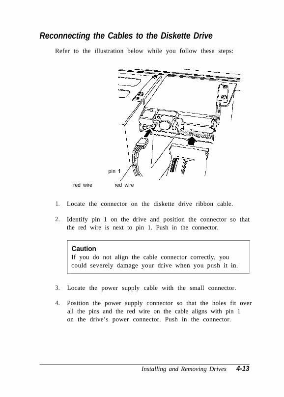
Reconnecting the Cables to the Diskette Drive
Refer to the illustration below while you follow these steps:
pin
red wire red wire
1. Locate the connector on the diskette drive ribbon cable.
2. Identify pin 1 on the drive and position the connector so thatthe red wire is next to pin 1. Push in the connector.
CautionIf you do not align the cable connector correctly, youcould severely damage your drive when you push it in.
3. Locate the power supply cable with the small connector.
4. Position the power supply connector so that the holes fit overall the pins and the red wire on the cable aligns with pin 1on the drive’s power connector. Push in the connector.
Installing and Removing Drives 4-13

Removing a Hard Disk Drive From the MountingBracket
Follow these steps if you need to remove the hard disk drivefrom the bracket:
4.
5.
Disconnect the cables from any drives installed in themounting bracket. Grasp the connectors and pull themstraight out so you do not bend the pins; do not pull on thecables.
Remove the screws securing the bracket to the drive bay andbrace.
Slide the bracket away from the front of the computer and liftit out.
P
Remove the screws securing the hard disk drive to thebracket and slide the drive out of the bracket.
Replace the bracket using the instructions on page 4-8.
4-14 Installing and Removing Drives
Installing a Drive in an External Drive BayYour system comes with two externally accessible drive bays.You can use these bays to install any of the following: diskettedrive, hard disk drive, CD-ROM drive, tape drive, or opticaldrive.
If you are installing a diskette drive or a tape drive with astandard 5.25-inch diskette drive connector, you can connect itusing the diskette drive cable that came with your system. Ifyou are installing a hard disk drive or drive with a differenttype of connector, you may need to purchase a different cable.
If you are installing a second hard disk drive, you need tocheck the settings of the drive’s jumpers to be sure they arecorrect for your configuration. A table of jumper settings forhigh-capacity EPSON drives is included in Appendix A. If yourdrive is not listed or you need more information, see thedocumentation that came with your drive or contact themanufacturer.
Before you can install a drive in one of the external bays, youmust first remove the mounting bracket containing the diskettedrive (and possibly a hard disk drive). See page 4-2 forinstructions.
This section includes steps for the following procedures:
0 Attaching mounting frames to the drive (if necessary)
0 Installing the drive in the bay
0 Connecting the drive cables
Installing and Removing Drives 4-15

Attaching Mounting Fames to the Drive
If you are installing a 3½-inch wide drive, you need to attachmounting frames to the drive. If you are installing a drive thatalready has mounting frames on it, see if it also has a plasticguiderail and metal grounding plate attached to it. If so, followstep 1 on page 4-5 to remove the guiderail and grounding plate.Then go to “Installing the Drive” on page 4-17.
Follow these steps to attach mounting frames to a drive:
1. Locate the two mounting frames and four screws that camewith the drive.
2. As shown below, place a mounting frame on one side of thedrive and align it so that the oval holes in the frame arepositioned over the holes in the drive. Then secure themounting frame to the drive with the two screws.
mounting frame
3. Repeat step 2 to attach a mounting frame to the other side ofthe drive.
4-16 Installing and Removing Drives

Installing the Drive
Follow these steps to install a drive in the upper or lowerexternal drive bay:
1. Remove the faceplate from the drive bay by pushing it outfrom the inside of the computer.
Keep the faceplate in a safe place in case you remove a drivelater (or you are installing a hard disk drive).
Installing and Removing Drives 4-17

2. Slide the drive through the slot into the bay until it is flushwith the front of the computer.
3. Align the slots at the side of the drive bay with the mountingholes in the drive or mounting frames. Then secure bothsides of the drive to the bay using the retaining screws.
4-18 Installing and Removing Drives

Connecting the Drive and Power Cables
If you are installing a diskette or tape drive, follow all the stepsbelow. If you are installing a hard disk drive, follow theinstructions on pages 4-9 through 4-12. Then go to step 5 below.
NoteIf you have one hard disk drive installed in the bracketbelow the diskette drive and will install and a second harddisk drive in the external bay, you need to purchase a newhard disk drive cable that can reach both drives.
If you are installing another type of drive, see thedocumentation that came with it to connect the drive cable;then go to step 3 below to connect the power supply cable.
1. Locate the diskette drive ribbon cable; the connector in themiddle is already connected to the system board.
2. If you are installing a drive with a card-edge connector, makesure you align the key-way (the plastic divider) with thegap in the drive connector, as shown below.
gap
key-way
Installing and Removing Drives 4-19

If you are installing a 3.5-inch diskette drive with a headerconnector, see page 4-13 for instructions on connecting thecable.
3. Locate one of the power supply cables that lead from thepower supply. (They have multi-colored wires and a plasticconnector on the end.)
4. Align the notched corners of the power supply cableconnector with the notched corners of the drive’s powerconnector (such as the one shown below). Make sure theholes lit over all the pins and then push in the connector.
notchedcorners
CautionIf you do not align the connectors correctly, you couldseverely damage your drive when you push them in.
4-20 Installing and Removing Drives

5. If you installed a hard disk drive in one of the external bays,replace the faceplate. Insert one side of the plate, thengently press on the other side until it snaps into place.
After you have completed installation of the drive in theexternal bay, you must replace the drive mounting bracket andreconnect the cables. See page 4-8 for instructions.
Removing a Drive from an External BayTo remove a drive from an external bay, follow these steps:
1. Remove the drive mounting bracket. See page 4-2 forinstructions.
2. Disconnect both the ribbon cable connector and the powercable connector from the drive you are removing from theexternal bay.
3. Remove the screws securing the drive.
Installing and Removing Drives 4-21

4. Reach behind the drive and gently push it to the front of thebay; then pull it out of the slot.
5. Once you have removed the drive, replace the faceplate byinserting one side of the plate, then gently pressing on theother side until it snaps into place.
6. Replace the drive mounting bracket and reconnect the cables.See page 4-8 for instructions.
Post-installation ProceduresAfter you install or remove your drive(s) and replace the coveron your computer, you need to run the SETUP program todefine your new configuration. See Chapter 1 for instructions.
4-22 Installing and Removing Drives
Chapter 5
Troubleshooting
If you have any problems as you set up and use yourcomputer, refer to this chapter. You can correct most problemsby adjusting a cable connection, repeating a softwareprocedure, or resetting the computer.
The troubleshooting suggestions in this chapter are organizedin general categories, such as “The computer will not start.”Within each category, a more specific problem is describedwith possible solutions.
If the suggestions here do not solve the problem, contact yourAuthorized EPSON Servicer or the EPSON Connection. See“Where to Get Help” in the Introduction of this manual forinstructions.
Identifying Your SystemWhen you request technical assistance, be ready to provide theserial number of your computer, its system BIOS versionnumber, its configuration (including the type of disk drives,monitor, and option cards), and the names and versionnumbers of any software programs you are using.
Troubleshooting 5-1

Use these guidelines to locate information about your system :
Serial number: Look on the back panel of thecomputer to find the serial number.
System BIOS version:
Systemconfiguration:
Restart your system. You’ll see thesystem BIOS version numberdisplayed on the screen duringpower-on diagnostics.
Start SETUP and select the SystemSummary option to see yoursystem‘s configuration.
MS-DOS version:
Software versions:
CONFIG.SYS:
AUTOEXEC.BAT:
VER
and press Enter to see the MS-DOSversion number.
In Windows applications, selectAbout from the Help menu. Asyour software application starts, itusually displays a version numberon the banner screen. Also, you cancheck your software manual.
At the MS-DOS prompt, typeT Y P E C : \ C O N F I G . S Y S and p re s sEnter to see a listing of yourCONFIG.SYS file, which containssystem configuration commands.
At the MS-DOS prompt, typeT Y P E C : \ A U T O E X E C . B A T a n dpress Enter to see a listing of yourAUTOEXEC.BAT file, whichcontains system startup commands.
5-2 Troubleshooting

The Computer Will Not Start
The power light is on, but the computer does not start.
Make sure the boot options in SETUP are set to access drive A.Then place a bootable diskette in drive A and turn on thecomputer again.
CautionIf you turn off the computer, always wait at least 20 secondsbefore turning it back on. This prevents damage to thecomputer’s electrical circuitry.
The computer does not start and the powerlight is not lit
Make sure the power cord is securely connected to both the ACinlet on the back panel and an electrical outlet.
The power cord is securely connected, but the computerstill does not start.
Check the electrical outlet for power. Turn off your computerand unplug the power cord. Plug a lamp into the outlet andturn it on.
You installed or removed system components, and nowyour computer does not start.
Check to make sure you have reconnected all the internal andexternal cables correctly.
You may have installed option cards that exceed the system’spower requirements. Check the power requirements inAppendix A.
Troubleshooting 5-3

You may have installed a SIMM incorrectly. If the systemdoesn’t detect memory, it won’t start. Check that your SIMM(s)are securely installed in their sockets.
If you replaced the microprocessor, make sure the newprocessor chip is installed correctly. Also make sure thejumpers are set correctly and pin 1 on the chip is connectedwith pin 1 on the system board. See Chapter 3.
The Computer Does Not Respond
The computer locks up.
Wait a few moments; if your computer does not respond after areasonable length of time, press Ctrl Alt Del. If that doesn’twork, press the RESET button.
You may have installed SIMMs with an incorrect access speed.Install the correct SIMMs. (See Chapter 3.)
Your system may have over-heated. Make sure you have anadequate heat sink installed on your microprocessor, ifnecessary. See Chapter 3 for more information.
You reset the computer, but it still does not respond.
Try turning the computer off, wait 20 seconds, and turn it onagain.
Your computer suddenly stops operating.
You may have overloaded the power supply. See your optioncard manual(s) for the power requirements for your optioncard(s). Then check Appendix A to see if you have exceededthe option slot power limits.
5-4 Troubleshooting

Keyboard Problems
The screen displaysa keyboard error message when youturn on or reset the computer.
Make sure the keyboard is securely connected to the keyboardport and not the mouse port. Although these ports look alike,they cannot be used interchangeably.
Nothing happens when you type on the keyboard.
The Lockout Timer may be set in SETUP. This optioninactivates the keyboard for a specified period of time after thesystem returns to an active mode from a low-power standbymode. This delay gives Energy Star compliant monitors thetime they need to return to an active mode. Wait a few secondsand try again.
See “The Computer Does Not Respond,” above
The cursor keys on the numeric keypad do not workproperly.
If the Num Lock light in the upper right corner of the keyboardis lit, press NumLock to turn off the function.
Mouse Problems
Yourmouse isn’t working properly or you see an auxiliarydevice error message.
Make sure the mouse cable is securely connected to the MOUSEport and not the keyboard (K/B) port. Also make sure youinstalled the mouse driver correctly (if necessary). See thedocumentation that came with your mouse for instructions.(Windows automatically installs a mouse driver when youinstall the program.)
Troubleshooting 5-5
Monitor Problems
There is no display on the screen.
Check that the monitor’s power switch is on and that its powerlight is on.
Also, the computer may be in low-power standby mode. Whenyou press a mouse button or a key on the keyboard, see if themonitor displays an image.
The power light is on, but you still do not see anything onthe screen.
Press a mouse button or a key on the keyboard to see if thecomputer is in low-power standby mode. Also, check thebrightness and contrast controls.
If you still do not see anything on the screen, make sure themonitor is securely connected to the computer.
If you installed a display adapter card, make sure your monitortype matches the card type. Also be sure you set the correctdisplay type in SETUP (see Chapter 1) and that the mainsystem board jumpers are set correctly (see Chapter 3).
If you are running an application program, see if you need toset up the program for the type of monitor and display adapteryou have. Also make sure you are using the appropriatemonitor and display adapter for your software.
The powerswitch is on but the powerlight is not on.
If the monitor is Energy Star compliant, it may be in low-powerstandby mode. Press a mouse button or a key on the keyboardto activate the monitor.
Turn off the monitor’s power, wait five seconds, and turn itback on.
5-6 Troubleshooting

If the light still does not come on, check the electrical outlet forpower. Turn off your monitor and unplug it from the outlet.Then plug a lamp into the wall outlet and turn it on. If the lightturns on, your monitor may be faulty.
Diskette Problems
You see a diskette error message.
Reinsert the diskette, making sure you insert it all the way. Ifthe drive has a latch, turn it down to secure the diskette.
Also, check to see that you have inserted the right type ofdiskette in the drive. For example, make sure you are notinserting a high-density diskette in a double-density drive.
If reinserting the diskette does not solve the problem, insert thediskette in another diskette drive of the same type. If you canread the diskette in a different drive, your drive may be faulty.
The diskette is the tight type, but you still see an error.
Check that the diskette is not write-protected, preventing thedrive from writing to the diskette.
Make sure the diskette is formatted. See your operating systemdocumentation for instructions on formatting diskettes.
The system may have the Diskette Access option inSETUP enabled. If you entered a User level password whenyou started the system but this option is set to a Supervisorlevel, you see an error when you access the drive.
You may have a defective diskette. Try copying the files fromthe bad diskette to a new diskette.
Troubleshooting 5-7
Something is wrong with the data in the files
If you are using MS-DOS, run CHKDSK to repair the files. Youmay also be able to use special utilities or diagnostics to solvethis problem.
Diskette Drive Problems
A newly installed diskette drive is not working properly.
Make sure you have installed the drive correctly and check allthe cable connections.
You see a diskette drive error when you start your computer.
Run the SETUP program and configure your system for thecorrect type of diskette drive.
The diskette drive is making loud or unusual noises
Contact your Authorized EPSON Servicer or the EPSONConnection.
Hard Disk Drive Problems
A newly installed hard disk drive is not working properly orits performance is not what you expect.
Make sure you have installed the drive correctly and check allcable connections. Also, check the jumper settings on yourdrive.
Some hard disk drives do not support the Energy Star featureson your system. You may need to disable these features inSETUP.
5-8 Troubleshooting

You see a hard disk drive error when you start your system.
Run SETUP and check that your system is auto-sensing thecorrect drive type. If auto-sensing is enabled and SETUPdisplays information that does not match your drive, you mayneed to define your own drive type. See Chapter 1.
Make sure the jumpers on the system board are set correctly.Jumpers JB and JE enable or disable the IDE hard disk drivecontroller. See Chapter 3 for jumper information.
Make sure the jumpers on the hard disk drive are set correctly.See the documentation that came with the drive for moreinformation.
You ate unable to store data on the hard disk drive.
If the hard disk drive has been in low-power standby mode,make sure the drive has had time to achieve its full operatingspeed before you try to write data to it.
If your drive was not configured, make sure you havepartitioned and formatted it correctly for your operatingsystem. See your operating system manual for instructions.
Also, make sure your hard disk drive has been physicallyformatted by the manufacturer. (All EPSON-supplied drivesare physically formatted at the factory.) If it has not beenphysically formatted, use the format utility that came with thedrive to format it before you partition it or install the operatingsystem. (Note that a physical format is different fromsoftware-based formatting commands, such as the MS-DOSFORMAT command.)
Troubleshooting 5-9

You have been using your hard disk drive successfully forsome time but notice a reduction in performance.
The data on the disk may have become fragmented. Back up allyour data and use a disk compaction utility to reorganize thefiles on your disk.
If you cannot access data on your hard disk or you are seeingread/ write errors, the disk may have a physical problem.Contact your Authorized EPSON Servicer or the EPSONConnection.
Password Problems
You have forgotten your password.
You must discharge your CMOS memory. To do this, youneed to change the setting of jumper J30 to position 3-4. SeeChapter 3 for details on changing the jumper setting.
After you have changed J30, restart your system, leave it on fora few seconds, then turn it off again. This resets the SETUPvalues to their factory defaults. Both the Supervisor and theUser passwords are disabled.
Set J30 back to position 2-3. Then turn the computer on again.Use SETUP to set a new password, if you want one.
5-10 Troubleshooting

Software Problems
The application program does not start.
Check that you are following the correct procedure for startingthe program and that it is installed correctly. If you do not havea hard disk, make sure the correct diskette is in the diskettedrive. If you need help, contact your software manufacturer.
The application program is having trouble reading a keydisk.
You may be running an application that requires a slowerprocessor speed. Change your processor speed using thekeyboard commands described in Chapter 2.
The application program is having trouble reading from orwriting to the hard disk drive.
If you have enabled the Fixed Disk Timeout option inSETUP, your application may be timing out during the fewsecond delay when the hard disk drive returns to its operatingspeed after being in standby mode. Disable this option inSETUP (see Chapter 1).
Yourapplication haslocked the computer, making itunresponsive to keyboard commands
Reset the computer and try again. If resetting the computerdoes not help, turn it off, wait 20 seconds, then turn it on again.
Some software, like OS/ 2®, UNIX®, or NetWare®, needs aminimum of 8MB to 16MB of RAM to work correctly. Checkyour software documentation for the minimum memoryrequirements. If necessary, add additional memory using theinstructions in Chapter 3.
Troubleshooting 5-11

Printer Problems
The printer or scanner does not work at all.
Check that the printer or scanner has power and is properlyconnected to the computer. Also make sure your printer haspaper in it. If you are using more than one serial port and one isfor your printer, check the primary and secondary port settings(COM1 and COM2) in your application program.
If you connected a scanner or a parallel port network adapter tothe parallel port, make sure you set the port for bidirectionaloperation (PS2 mode) in the SETUP program, as described onpages 1-11 and 1-13.
The printer prints garbled information.
Check the printer manual for the printer’s correct DIP switch orcontrol panel settings. Also, make sure you have the properdrivers installed for your printer and make sure you’veselected the correct printer within your software application.
Option Card Problems
A newly installed option card is not working correctly.
Make sure the option card is installed correctly and iswell-seated in its slot. Run SETUP to update your configurationafter you install the card and perform setup procedures for anysoftware you are using with the card.
See the documentation that came with the option card to setany necessary DIP switches or jumpers on the card. Thecomputer may also have some jumpers that must be set for theoption card to work properly. See Chapter 3 for system jumperinformation.
5-12 Troubleshooting

Your system may need to operate at the slower processor speedto access the device. Try reducing the processor speed (seeChapter 2).
Make sure you install option cards that meet the system’spower requirements. See Appendix A.
Make sure the option card is not touching any other card. Alsomake sure the card isn’t touching the CPU or any fan or heatsink you have attached to the CPU.
If a fan or heat sink is attached to the CPU, don’t install anoption card in the lowest 16-bit option slot.
An external device connected to the option card is notworking correctly.
Make sure you are using the proper cable to securely connectthe device to the card.
Memory Module Problems
The memory count displayed by the power-on diagnosticsprogram is incorrect.
You may have installed the SIMMs incorrectly. They may bethe wrong type or speed, or they may not be inserted all theway. See Chapter 3 for information on installing SIMMs.
If you have installed a gold-plated SIMM in the sockets, thesocket may have corroded slightly. Remove the SIMM andclean the gold-plated connection; then reinstall the SIMM.
Troubleshooting 5-13

Controller Problems
You see a controller error for the drive controllers or the I/Oport controllers when you start your system.
The indicated controller on your system board may be faulty.If you have an option card with a controller that will work withyour device, you can install it and change the jumper settingson the system board to disable the built-in controller. You canthen continue to use your system until it is convenient for youto have it serviced.
External Cache Problems
The amount of cache displayed by the power-ondiagnostics program is incorrect.
You may have installed the external cache chips incorrectly.They may be the wrong type, or they may not be inserted allthe way. Also, make sure the tag chip you’ve installed has a20ns access speed.
Also, you may not have changed the SETUP program or thejumpers to recognize the new cache. Make sure you have setthe Ex te rna l cache op t ion to Enab led and se t bo th theSys tem shadow and the Video shadow opt ions toEnabled. You can access these options from the MemoryCache and Memory Shadow options on the Advanced SystemSetup screen.
See Chapter 3 for instructions on changing the jumper settingsor information on installing external cache; see Chapter 1 forinstructions on using the SETUP program.
5-14 Troubleshooting

Appendix A
Specifications
CPU and Memory3 2 - b i t C P U
Green PCenergy saver
System speed
Intel or Cyrix 486SX, DX, or DX2processor; upgradable to faster, morepowerful processors, including theSX2/50, DX4/ 75 or /100, or PentiumOverDrive
Energy Star compliant, low-powerstandby mode (using less than 30 Watts)for the hard disk drive and the videosignals the computer sends to the monitor;time periods selectable in SETUP
Fast and slow processor speeds available;fast speed is the speed of your processorand slow speed is 8 MHz; speed selectionthrough keyboard commands
ISA bus speed for all processors is8.33 MHz; local bus video operates at thespeed of your processor; at fast speed,DX2/ 50 and DX2/ 66 processors runinternally at 50 and 66 MHz, andexternally at 25 and 33 MHz, respectively;local bus speeds for DX2 processors are25 and 33 MHz, respectively
Specifications A-1

Memory
Video RAM
Shadow RAM
Memoryrelocation
Cache
Mathcoprocessor
Clock/calendar
4MB or 8MB RAM standard on a SIMM;expandable to 64MB using 1MB, 2MB,4MB, 8MB, 16MB, and 32MB SIMMs;SIMMs must be tin-plated, 72-pin, 32-bitor 36-bit, fast-page mode type with accessspeed of 80ns or faster
128KB Phoenix® system BIOS, video BIOS,and SETUP code located in EPROM onmain system board
512KB or 1MB DRAM; expandable to 1MBusing four, 20-pin, 70ns, 256KB DIP chips
Supports shadowing of system and videoBIOS ROM into RAM
Supports relocation of 256KB of memoryfrom A0000h to BFFFFh and D0000h toEFFFFh to extended memory
8KB of internal cache; supports 64KB,128KB, or 256KB of external cache using28-pin, 8K x 8 or 32K x 8,20ns DIP chips
Math coprocessor built into themicroprocessor for DX, DX2, and systemsupgraded to a Pentium OverDriveprocessor
Real-time clock contained in the 82C491system controller chip along with 64 bytesof CMOS RAM backed up by anintegrated battery
A-2 Specifications

ControllersVideo Cirrus Logic® GD5426 high-speed SVGA
local bus controller supports resolutionsup to 1280 x 1024 in 16 colors (with 1MB ofVRAM); True Color support in 640 x 480resolution (with 1MB of VRAM)
Diskette Controller on main system board supportsup to two diskette drives or one diskettedrive and one tape drive
Hard disk IDE interface on main system boardsupports up to two IDE hard disk driveswith built-in controller; BIOS provideshard disk auto-sensing function
lnterfacesMonitor
Parallel
VGA interface for fixed or multi-frequencymonitor built into system board;low-power standby mode for Energy Starcompliant monitors; 15-pin, D-shellconnector
One standard S-bit parallel bidirectionalinterface built into main system board;25-pin, D-shell connector; operationcontrollable by SETUP option
Serial Two RS-232C, programmable,asynchronous interfaces built into mainsystem board; 9-pin, D-shell connectors
Keyboard PS/ 2 compatible keyboard interface builtinto main system board; 6-pin, mini DINconnector
Specifications A-3

Mouse PS/ 2 compatible mouse interface built intomain system board; 6-pin mini DINconnector
Option slots Three full-length and two half-length,16-bit I/O expansion slots; ISAcompatible, 8.33 MHz bus speed; onDX/ 50, DX2, or Pentium OverDrivesystems, one slot may be unavailablebecause of the CPU heat sink/ fan assembly
Game port 10-pin game port header on main systemboard; accessible by removing game portslot cover on back panel; operationselectable by jumper
Speaker Internal
Mass Storage Internal mounts for:One 3½-inch wide, one-inch high internaldrive
Externally accessible mounts for:One 3½-inch wide, one-inch high driveand two 5¼-inch wide, half-height drives
Diskette drives 3.5-inch diskette drive, 720KB or 1.44MBstorage capacity
5.25-inch diskette drive, 360KB or 1.2MBstorage capacity
Combination 3.5-inch/ 5.25-inch diskettedrive
Hard diskdrives
3½-inch or 5¼-inch hard disk drive(s), upto half-height size
A-4 Specifications

Otherdevices Half-height tape drive, CD-ROM, opticaldrive, or other storage device; 5¼-inch or3½-inch wide with mounting frames
Keyboard Detachable, two-position height; 101 or102 sculpted keys; country-dependentmain typewriter keyboard; numeric/cursor control keypad; four-key cursorcontrol keypad; 12 function keys
Mouse Detachable, two-button, PS/ 2 compatible
SETUP Program Stored in ROM; accessible by pressing F2during boot
Systemsecurity
User and Supervisor level passwordsavailable for system boot or diskette access
Virusprotection
Write protection feature for the hard diskdrive boot sector; periodic remindermessage for running virus detection utility
Physical Characteristicswidth 16.8 inches (430 mm)
Depth 15.6 inches (400 mm)
Height 4.4 inches (112 mm)
Weight 17 lb (7.7 kg) with one diskette drive, butwithout a keyboard
Specifications A-5

Power Supply
Type
Input ranges
Maximumoutputs
Frequency
Cables
200 Watt, UL/ TUV/ CSA listed, fan-cooled
90 to 130 VAC or 180 to 260 VAC;switch-selectable for 115 VAC and230 VAC input current
+5 VDC at 20 Amps, -5 VDC at 0.5 Amp,+12 VDC at 8.0 Amps, -12 VDC at 0.5 Amp
47 to 60 Hz
Option Slot Power Limits
Two to main system board; five to massstorage devices
Maximum current +5 Volts -5 Volts +12 Volts -12 Volts
For all slots 12 Amps 0.4 Amp 4 Amps 0.4 Amp
* Based on a system containing one hard disk drive and one diskette drive
Environmental Requirements
Condition
Temperature
Humidity(non-condensing)
Altitude
Operatingrange
41° to 95° F(5° to 35° C)
8% to 80%
-330 to 9,900 ft(-100 to3,000 m)
Non-operatingrange
-4° to 140° F(-20° to 60° C)
-330 to 39,600 ft(-100 to12,000 m)
Storage range
-4° to 140° F(-20° to 60° C)
-330 to 39,600 ft(-100 to12,000 m)
A-6 Specifications
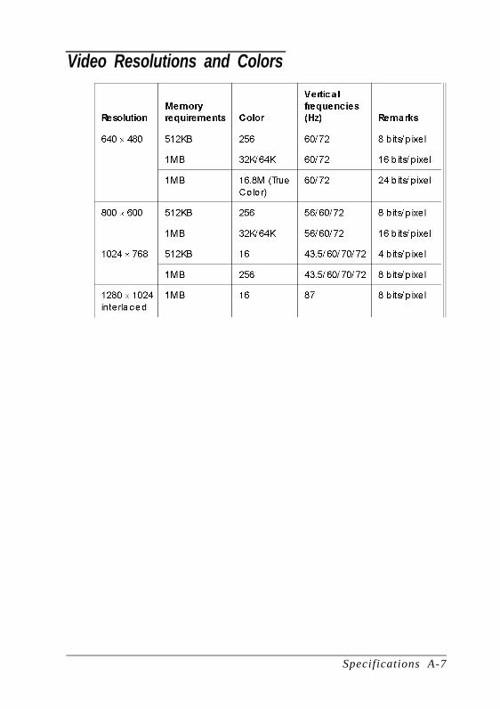
Video Resolutions and Colors
Specifications A-7
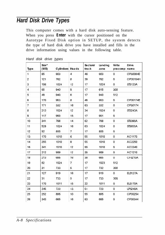
Hard Disk Drive TypesThis computer comes with a hard disk auto-sensing feature.When you press Enter with the cursor positioned on theAutotype Fixed Disk option in SETUP, the system detectsthe type of hard disk drive you have installed and fills in thedrive information using values in the following table.
Hard disk drive types
A-8 Specifications

Hard disk drive types (continued)
* Actual formatted size may be slightly different than size on drive label; youcannot change thisvalue.
Specif ications A-9

Drive Option lnformationHard disk drive options for high-capacity, 1-inch IDE drives
* Select 1 or none for the precomp value. If neither of these optionsareavailable, select the maximum available precomp value.
A-10 Specif ications

IDE hard disk drive jumpersettings
* CS(cable selection) can be jumpered for any configuration. When CSisused, the drive is a master if pin 28 isgrounded and a slave if pin 28 is notgrounded.
Options Available from EPSONMany options for supplementing this product are availablefrom EPSON, including the following:
MonitorsKeyboardsMass storage devicesPrintersOperating system software
Call your nearest marketing location for more informationabout specific options.
Specifications A-11

Tested Operating EnvironmentsAlthough your system will run most software applications,the following operating environments have been tested forcompatibility with your system.
Microsoft MS-DOS 3.1 and laterNovell® DR DOS®Novell NetWare 2.2, 3.12, and 4.01Novell NetWare LiteIBM® OS/ 2SCO® UNIXSCO Open DesktopMicrosoft Windows 3.0 and laterMicrosoft Windows WorkGroupsMicrosoft Windows NT
Your system has also received Novell’s “Yes, NetWare testedand approved” certification as a workstation and a server. Asnew environments become available, these also will be tested.
DMA Assignments
Level 1 Assigned device
DMA0 Reserved (8-bit)
DMA1 Reserved (8-bit)
DMA2 I Diskette drive controIler (8-bit) IDMA3 Reserved (8-bit)
DMA4 Cascade for DMA controller
DMA5 Reserved (16-bit)
DMA6 Reserved (16-bit)
DMA7 Reserved (16-bit)
A-12 Specifications

Hardware Interrupts
IRQ no. Function
IRQ0 Timer output
IRQ1 Keyboard
IRQ2 Cascade from IRQ controller 2
IRQ3 Serial port 2
IRQ4 Serial port 1
IRQ5 Parallel port 2
IRQ6 FDD controller
IRQ7 Parallel port 1
IRQ8 Real-time clock
IRQ9 Reserved
IRQ10 Reserved
IRQ11 Reserved
IRQ12 PS/2 mouse
IRQ13 Math coprocessor
IRQ14 HDD controller
IRQ15 Reserved
Specif ications A-13

System Memory Map
Memory add ress range Usage
000000h to 09FFFFh 640KB base memory
0A0000h to 0BFFFFh 128KB video memory
0C0000h to 0C7FFFh 32KB video ROM BIOS
0C8000h to 0DFFFFh 32KB externaI adapter ROM BIOS
0E0000h to 0FFFFFh 128KB system ROM BIOS
100000h to FDFFFFh Extended memory
FE0000h to FFFFFFh 128KB of ROM remapped from 0ED000h to
0FFFFFh
System l/O Address Map
Hex address
000-01F
020 - 03F
022 - 024
034, 038, 03C
040 - 05F
060 - 06F
070 - 07F
080 - 09F
0A0 - 0BF
0C0 - 0DF
OF0
OF1
0F8 -OFF
1F-1F8
200 - 207
278 - 27F
280 - 2DF
Assigned device
DMA controller 1,8237
Interrupt controller 1,8259
Chip set configuration registers
AD12 chip set configuration registers
Timer, 8254
Keyboard controller, 8042
NMI (non-maskable interrupt)
DMA page register, 74LS612
Interrupt controller 2,8259A
DMA controller 2,8237
Clearmath coprocessor
Reset math coprocessor
Math coprocessor
Hard disk
Game l/O
Parallel printer port 2
Alternate enhanced graphicsadapter
A-14 Specifications

System I/O address map (continued)
Specif ications A-15
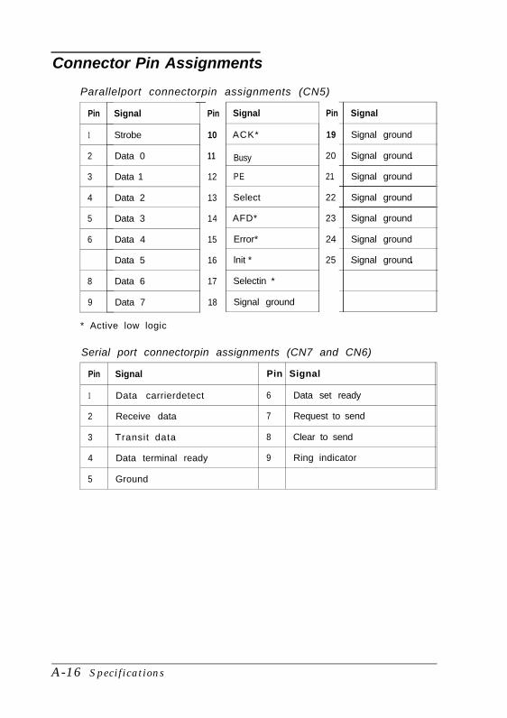
Connector Pin Assignments
Parallelport connectorpin assignments (CN5)
Pin
1
2
3
4
5
6
8
9
Signal
Strobe
Data 0
Data 1
Data 2
Data 3
Data 4
Data 5
Data 6
Data 7
Pin
10
11
12
13
14
15
16
17
18
Signal
ACK*
Busy
PE
Select
AFD*
Error*
lnit *
Selectin *
Signal ground
Pin
19
20
21
22
23
24
25
Signal
Signal ground
Signal ground
Signal ground
Signal ground
Signal ground
Signal ground
Signal ground
* Active low logic
Serial port connectorpin assignments (CN7 and CN6)
Pin Signal Pin Signal
1 Data carrierdetect 6 Data set ready
2 Receive data 7 Request to send
3 Transit data 8 Clear to send
4 Data terminal ready 9 Ring indicator
5 Ground
A-16 Specifications

Glossary
A batch file that MS-DOS executes automatically each time youturn on or reset the computer. This file contains startupcommands that tell the computer what to do each time youturn it on.
BIOS
Basic Input/ Output System. Routines stored in ROM thathandle the basic input/ output functions of the operatingsystem.
Cache
A high-speed memory buffer that stores frequently used datawhere your microprocessor can access it faster. Your computerincludes 8KB of internal cache in the microprocessor and hassupport for up to 256KB of external cache on the main systemboard.
CONFIG.SYS file
A special system file that MS-DOS executes each time you turnon or reset the computer. You use this file to customize yoursystem by installing device drivers, setting limits for files andbuffers, and specifying MS-DOS commands to be run duringstartup.
CPU
Central Processing Unit. The integrated circuit (chip)responsible for integrating program instructions, performingcalculations, and controlling all input and output operations.
Glossary 1
Driver
A program that controls a specific piece of equipment in thesystem. Examples of drivers include expanded memorymanagers, display drivers, printer drivers, and mouse drivers.
IDE
Integrated Drive Electronics. A type of hard disk drive interfacein which the controller is on the drive instead of on a controllercard. Your computer includes an interface on the main systemboard for up to two IDE hard disk drives.
ISA
Industry Standard Architecture. The 8- or 16-bit bus standarddeveloped for IBM compatible computers.
Jumper
A small moveable plug that connects two pins on a device’scircuit board. A jumper determines the operation of a particularfunction.
Local bus
An internal group of wires that sends information from themicroprocessor directly to the video controller in the computer.Local bus video provides increased performance.
Memory module
A small circuit board, commonly called a SIMM (single in linememory module), that contains surface-mounted memorychips. You can add memory modules to the main system boardto expand your computer’s memory.
2 Glossary

Microprocessor
See CPU.
Parallel
A way of organizing communications between two pieces ofcomputer equipment, in which the signals that make up eachcharacter are sent simultaneously. See also Serial.
Power-on diagnostics
A set of testing routines the computer performs automaticallyevery time you turn it on.
RAM
Random Access Memory. The portion of the computer’smemory that runs programs and temporarily stores data whileyou work. See also ROM.
Real-time clock
A battery-powered clock in the computer that keeps track ofthe current time and date even when the computer’s power isoff.
Read Only Memory. The portion of the computer’s memorythat contains permanent instructions and cannot be modified.Unlike RAM, ROM retains its contents even after you turn offthe computer. See also RAM.
RS-232C
A standard serial interface. The computer has a connector thatlets you attach an RS-232C-compatible device to your computer.
Glossary 3

Serial
A way of organizing communications between two pieces ofcomputer equipment in which the signals that make up eachcharacter are sent sequentially. See also Parallel.
Shadow RAM
The function that copies the system BIOS and video BIOS fromROM into RAM to speed up performance.
SIMM
See Memory Module.
VGA
Video Graphics Array. A high-resolution (640 x 480) displayadapter standard.
Write-protect
To prevent a diskette from being overwritten. When a disketteis write-protected, you cannot erase, change, or record over itscontents.
4 Glossary

Index
AAC power inlet, 1-4 -5, 5-3Advanced Chipset Control option,
1-13Advanced System Setup option,
1-11-13Altitude, A-6Application programs
compatibility, A-12exiting, 1-6, 2-3installing, 1-20problems, 5-11requiring slow speed, 2-5stopping, 2-2timing requirements, 2-5versions, 5-2
Auto-sensing, 1-10, 5-9, A-3, A-8AUTOEXEC.BAT file, 5-2Autotype Fixed Disk option, 1-10,
A-8
BBack panel, 1-4, 3-2Banks
cache, 3-21SIMM, 3-9 -10
Battery, Intro-2, 1-7, 3-7, A-2Bays
external drive, 1-6, 4-1, 4-15,4-17 -18, 4-21 -22
internal drive, 4-1 -3, 4-8Bezel, 3-4BIOS
system, Intro-1 -2, 1-7, 1-10, 5-2,A-2 -3, A-14
video, Intro-1 -2, A-2Boot options, 1-13 -14, 5-3Booting system, 1-8, 1-10Brightness, 1-6, 5-6
Buttonspower, 1-6RESET, 1-6, 2-3
CCache memory
banks, 3-21configuration, 1-12, 3-21configuring, 1-12external, Intro-1, Intro-4, 3-20 -23,
5-14, A-2installing, 3-20 -23internal, Intro-1, A-2jumpers, 3-8, 3-22problems with, 5-14setting in SETUP, 1-12, 3-23sockets, 3-21
CardLAN, Intro-2modem, Intro-2option, see Option cards
CD-ROM, Intro-4, 4-1, 4-15, A-5Chipset registers, 1-13CHKDSK command, 5-8Clock, real-time, Intro-2, 1-9, A-2CMOS RAM, 1-7 -8, 1-19, 3-7, A-2Components
damaging, 3-3external, 1-4internal, 3-5
CompuServe on-line support, Intro-7CONFIG.SYS file, 5-2Configuration
cache, 1-12, 3-21drive, 1-10 -11, 4-22, 5-8-9errors, 1-8files, 3-26, 5-2SIMM, 1-10, 3-9 -10system, 1-7 -20, 5-1 -2
I n d e x 1

Connector pin assignments, A-16Contrast, 1-6, 5-6Controllers
diskette drive, A-3hard disk drive, 3-6, A-3I/O port problems, 5-14parallel port, A-3serial ports, A-3SVGA, Intro-2, A-3
Coprocessor, math, Intro-2, A-2Cover
removing, 3-2 -3, 4-1replacing, 3-4
CPU, see ProcessorCtrl Alt +, 2-5Ctrl Alt -, 2-5Ctrl Alt Del, 2-3, 5-4Ctrl Break, 2-2Ctrl C, 2-2Cursor, 1-8Customer support, Intro-6-7
DData
losing, 2-2saving, 1-6
Date, setting, 1-9Daylight savings time, 1-9Depth, computer, A-5Diagnostics, power-on, 1-6, 5-13Disk compaction utility, 5-10Diskette drive
bays, 1-6, 4-1, 4-15, 4-18, 4-21, A-4cable, 4-13, 4-19, 4-21caution, 4-20configuration, 1-10, 4-22, 5-8controller, A-3controlling access, 1-14, 5-7, A-5errors, 5-8faulty, 5-7installing, 4-1 -3, 4-8 -9, 4-13, 4-15 -21jumper, 3-6latch, 5-7
Diskette drive (continued)lights, 1-6post-installation, 4-22power cable, 4-19 -21, 5-8problems, 5-8removing, 4-1 -3, 4-21 -22support, Intro-2types, A-4
Diskette(s)access, controlling, 1-14, 5-7, A-5defective, 5-7formatted, 5-7key, 2-5, 5-11problems, 5-7type, 5-7write-protected, 5-7
Display adapters, 1-9, 5-6Display prompt, SETUP, 1-8, 1-14Display type option, SETUP, 1-9DMA assignments, A-12Drivers
mouse, 5-5printer, 5-12VGA, Intro-3, 1-20
EElectrical
circuitry, 5-3outlet, 1-4 -5, 5-3
Energy, conserving, 2-4Energy Star, Intro-1, Intro-3, 1-18,
2-4, 5-5 -6, A-1, A-3Environmental requirements, A-6EPSON Connection, Intro-3, Intro-6Ergonomic tips, 2-1 -2Errors
configuration, 1-8diskette drive, 5-8hard disk drive, 5-9keyboard, 5-5read/ write, 5-10
Extended memory, 1-10, A-14
2 Index

External cache, Intro-1, Intro-4,3-20 -23, 5-14, A-2
FFaceplate
removing, 4-17replacing, 4-22
Fixed Disk Setup option, 1-10 -11Fixed Disk Timeout option, 1-18Formatting
diskettes, 5-7hard disk drive, 5-9
Frequency, power supply, A-6Full-length option slots, 3-15-16, A-4Function keys, SETUP, 1-8
GGame port
access, 1-4jumper, 3-6specification, A-4
Green PC, Intro-3, 1-18, 2-4 -5, A-1Grounding plate, 4-5Grounding yourself, 3-3, 3-19, 3-24Guiderail, 4-5
HHalf-length option slots, 3-16 -17, A-4Hard disk drive
auto-sensing, 1-10 -11, 5-9, A-3, A-8bays, 4-1, 4-14cable, 4-4 -5, 4-9 -12, 4-14 -15, 4-20compaction utility, 5-10configuration, 1-10 -11, 4-22, 5-9controller, 3-6, A-3errors, 5-9formatting, 5-9grounding plate, 4-5guiderail, 4-5installing, Intro-4, 4-1 -12, 4-15 -21jumpers, 3-6, 4-4, 5-8, A-11light, 1-6mounting frames, 4-4 -5
Hard disk drive (continued)option information, A-10 -11parameters, A-8 -10physical format, 5-9post-installation, 4-22preformatted, 1-11problems, 5-8 -10removing, 4-1 -3, 4-14, 4-21 -22SETUP option, 1-10 -11standby mode, Intro-3, 1-18, 2-4 -5,
5-9, 5-11, A-1support, Intro-2time-out, 1-18translation mode, A-10types, A-4, A-8 -9user-defined, 1-11
Hardware interrupts, A-13Heat sink
installing, 3-23, 3-26limitations, A-4
Height, computer, A-5Help screen, SETUP, 1-8Help, where to get, Intro-6 -7Humidity, A-6
II / O
address map, A-14 -15expansion slots, A-4port problems, 5-14
Indicator lightsdiskette drive, 1-6hard disk drive, 1-6monitor, 5-6power, 1-6, 5-3, 5-6speed, 1-6, 2-5
Inlet, power, 1-4 -5, 5-3Input ranges, power supply, 1-2 -3,
A-6Internal cache, Intro-1, A-2Internal components, 3-5Interrupts, hardware, A-13
Index 3
J MJumpers
battery, 3-7cache, 3-8, 3-22changing settings, 3-6-9diskette drive, 3-6game port, 3-6hard disk drive, 3-6, 4-4, 5-8, A-11main system board, 3-6 -9option card(s), 3-14parallel port, 3-6processor speed, 3-7, 3-26processor type, 3-7, 3-26serial ports, 3-6VGA controller, 3-6-7video card, 3-14
KK/ B port, Intro-1, 1-4, 5-5, A-3Key disk, 2-5, 5-11Keyboard
checking connections, 5-5errors, 5-5num lock, 5-5port, Intro-1, 1-4, 5-5, A-3problems, 5-5processor speed commands, 2-5-6PSI 2 compatible, Intro-1, A-3specifications, A-5
Keypad, numeric, 2-5, 5-5Keys, SETUP function, 1-8
LLAN card, Intro-2Local bus, see VideoLockout timer option, 1-18, 5-5Low-level format. 5-9
Mass storage, Intro-2, Intro-4, 4-1,A-4 -5
Math coprocessor, Intro-2, A-2Memory
cache, see Cache memoryclearing, 2-3CMOS RAM, 1-7 -8, 1-19, 3-7, A-2extended, 1-10, A-14installing, see SIMMsinsufficient, 5-11map, A-14problems, 5-13RAM, Intro-4, 5-11, A-2relocation, A-2, A-14removing, see SIMMsROM, 1-7, 1-12, 1-19, A-2, A-14shadow, see Shadow RAMSIMMs, see SIMMssize, 1-10standard, A-2system, Intro-1, 1-10, 1-12, A-2, A-14video, see Video memory
Messages, error, see ErrorsMicroprocessor, see ProcessorModem, Intro-2Monitor
brightness, 5-6contrast, 5-6Energy Star compliant, Intro-3,
1-18, 2-4, 5-5 -6, A-1, A-3indicator light, 5-6port, 1-4power cord, 5-7power switch, 5-6-7problems, 5-6time-out, 1-18turning off, 1-6turning on, 1-5
Mounting frames, hard disk drive,4-4-5
4 Index

Mousedriver, 5-5port, Intro-1, 1-4, 5-5, A-4PSI 2 compatible, Intro-1, A-4 -5specifications, A-4 -5
NNetWare, A-12Network card, Intro-2Num lock, 5-5Numeric coprocessor, Intro-2, A-2Numeric keypad, 2-5, 5-5
OOn-line support, Intro-7Operating environments, A-12Operating range, A-6Operating system
diskette, 5-3installing, 1-20reloading, 2-3version number, 5-2
Optical drives, Intro-4, 4-1, 4-15, A-5Option cards
DIP switches, 3-14, 5-12installing, 3-14-17jumpers, 3-14power requirements, 3-14, 5-34,
5-13, A-6problems, 5-12removing, 3-8, 3-17
Option slotsavailable, Intro-2cover, 3-15 -17full-length, 3-15 -16, A-4half-length, 3-16 -17, A-4location, 1-4power limits, 3-14, 5-34, 5-13, A-6type, Intro-2, 3-14, A-4
Optional equipment, Intro-4, 1-2, 3-1,4-1, A-11
Outlet, electrical, 1-4 -5, 5-3OverDrive, Pentium, 3-25, A-1 -2, A-4
PParallel port
connector, 1-4controller, A-3jumper settings, 3-6operation, 1-11, 1-13, 5-12pin assignments, A-16type, Intro-1, A-3
Passwordon boot option, 1-16problems, 5-10Supervisor, 1-15 -16, 5-7, A-5User, 1-15 -16, 5-7, A-5
Pause key, 2-2Pause on POST errors, 1-14Pentium OverDrive, 3-25, A-1 -2, A-4Physical characteristics, A-5Pin assignments, A-16Post-installation procedures, 3-26,
4-22Post-SETUP procedures, 1-20Power
button, 1-6inlet, 1-4 -5, 5-3light, 1-6, 5-3, 5-6
Power cablecomputer, 1-5, 3-2, 3-4, A-6diskette drive, 4-19 -20, 5-8hard disk drive, 4-12monitor, 5-7
Power requirements, option cards,3-14, 5-34, 5-13, A-6
Power supplycables, 4-11 -12, 4-19 -20frequency, A-6input ranges, 1-2 -3, A-6limitations, 3-14, 5-4, A-6maximum outputs, A-6type, A-6voltage selector switch, 1-2 -3
Power-on diagnostics, 1-6, 5-13
Index 5

Printerchecking connections, 5-12drivers, 5-12problems, 5-12turning off, 1-6turning on, 1-5
Processorjumpers, 3-7, 3-26replacing, 3-24 -26socket, 3-23specifications, A-1types, Intro-1, 3-23upgrading, 3-23 -26
Processor speedchanging, 2-5 -6, A-1indicator light, 1-6, 2-5jumper, 3-7, 3-26keyboard commands, 2-5-6problems, 5-11
Programs, see Application programs
RRAM, see MemoryRAM, shadow, Intro-1 -2, 1-12, A-2,
A-14Read/ write errors, 5-10README files, Intro-3, 1-20Real-time clock, Intro-2, 1-9, A-2RESET button, 1-6, 2-3Resetting the computer, 1-7, 2-3, 5-2Resolutions, see Video resolutionsROM, 1-7, 1-12, 1-19, A-2, A-14RS-232C ports, see Serial ports
SSafety precautions, iii-iv, 1-5, 3-1, 3-3Scanner, 1-11, 1-13, 5-12Screen colors, A-7Screen resolutions, see Video
resolutionsSerial number, 5-2
Serial portsCOM1 and COM2, 1-4controller, A-3jumper settings, 3-6pin assignments, A-16reassigning, 3-6type, Intro-1
SETUP programadvanced chipset control, 1-13advanced system setup, 1-11 -12auto configuration, 1-13autotype fixed disk, 1-10, A-8boot options, 1-13 -14, 5-3cache memory, 1-12chipset registers, 1-13date and time, 1-9display prompt, 1-8, 1-14display type, 1-9drive configuration, 1-10 -11, 4-22,
5-8-9errors, 1-8exiting, 1-19factory default settings, 1-7, 1-19fixed disk setup, 1-10 -11fixed disk timeout, 1-18function keys, 1-8Green PC, 1-18hard disk drive, 1-10 -11, 4-22, 5-9help screen, 1-8lockout timer, 1-18main menu, 1-8memory cache, 1-12, 3-23memory shadow, 1-12password security, 1-15 -16, A-5pause on POST errors, 1-14post-SETUP procedures, 1-20saving settings, 1-19shadow memory, 1-12starting, 1-8 -9, A-5system memory, 1-10system security, 1-15 -17, A-5system setup, 1-9 -10
6 Index

SETUP program (continued)system summary, 1-14, 1-19user-defined, 1-11virus protection, 1-16 -17, A-5when to run, 1-7
Shadow RAM, Intro-1 -2, 1-12, A-2,A-14
SIMMsbanks, 3-9-10configuration, 1-10, 3-9-10gold-plated, 5-13incorrect type, 5-4installing, Intro-4, 3-9, 3-11 -12removing, 3-12-13sockets, 1-10, 3-9 -12, 5-13type, 3-9 -10, A-2
Slot cover, option, 3-15, 3-17Slots, option, see Option slotsSoftware, see Application programsSpeaker, A-4Speed, see Processor speedSpeed light, 1-6, 2-5SRAM chips, see Cache memoryStandby mode, Intro-3, 1-18, 2-4 -5,
5-5 -6, 5-9, 5-11, A-1, A-3Static electricity, 3-19Stopping a command or program,
2-2Supervisor password, 1-15 -16, 5-7,
A-5SVGA
controller, Intro-3, A-3drivers, Intro-4, 1-20interface, Intro-1, Intro-34, A-3jumpers, 3-6-7local bus, Intro-1, A-3utilities, Intro-4
System BIOS, Intro-1 -2, 1-7, 1-10,5-2, A-2 -3, A-14
System Security and Anti-Virusoptions, 1-15 -17, A-5
System Setup option, 1-9 -10System Summary option, 1-14, 1-19
TTag SRAM, 3-21Tape drive, Intro-4, 4-1, 4-15, A-3,
A-5Technical support, Intro-6 -7Temperature, A-6Time, setting, 1-9Time-out periods
hard disk drive, 1-18monitor, 1-18
Troubleshooting, 5-1 -14True Color support, Intro-1, A-3Turning off computer, 1-6Turning on computer, 1-5 -6
UUnpacking computer, 1-1 -2User password, 1-15 -16, 5-7, A-5User-defined hard disk drive, 1-11Utilities
disk compaction, 5-10VGA, Intro-3
VVGA, see SVGAVideo
BIOS, Intro-1 -2, A-2card jumpers, 3-14card option, 1-9colors, Intro-1 -2, A-3, A-7controller, Intro-2, A-3display type, 1-9interface, Intro-1, 1-4local bus, Intro-l, A-3memory, see Video memoryresolutions, Intro-1 -2, A-3, A-7standby mode, Intro-3, 1-18, 2-4,
5-5-6, A-1, A-3time-out, 1-18True Color, Intro-1, A-3
Index 7

Video memoryadding, Intro-1 -2, 3-18 -19DIP chips, 3-18-19, A-2supported resolutions, Intro-1 -2,
A-3, A-7type, 3-18, A-2
Virus protection options, 1-16 -17,A-5
Voltage selector switch, 1-2 -3
WWeight, computer, A-5Width, computer, A-5Windows
mouse driver, 5-5Work environment, 2-1 -2Write-protection, 5-7
Z
ZIF socket, 3-24-25
8 Index