cameras and image sensors - tohoku university …swk/lecture/ic2014/kagami_ic20140513.pdf ·...
TRANSCRIPT

Intelligent Control Systems
Cameras and Image Sensors
Shingo KagamiGraduate School of Information Sciences,
Tohoku Universityswk(at)ic.is.tohoku.ac.jp
http://www.ic.is.tohoku.ac.jp/ja/swk/

3Shingo Kagami (Tohoku Univ.) Intelligent Control Systems 2014.05.13
Basic Motivation
e.g. Vision-based Control of Robots
• image acquisition (today)• image processing (from June 3 and on)• robot control

4Shingo Kagami (Tohoku Univ.) Intelligent Control Systems 2014.05.13
Outline
• Lens and Optical Parts
• Image Sensors• CCD / CMOS sensors• Integration / Shutter Modes
• In-Camera Image Processing
• Image Data Transfer
• Dynamic Range Enhancement

5Shingo Kagami (Tohoku Univ.) Intelligent Control Systems 2014.05.13
Cameras and Image Sensors
lens
spatial low-pass filterwavelength filter
color filter
image sensor
sensor controllerin-camera processor
bus interfacecamera

6Shingo Kagami (Tohoku Univ.) Intelligent Control Systems 2014.05.13
Examples
USB camerawith unremovable lens
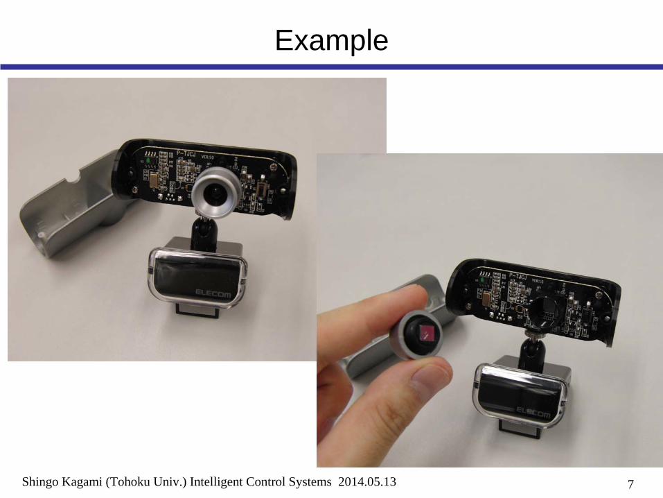
7Shingo Kagami (Tohoku Univ.) Intelligent Control Systems 2014.05.13
Example

8Shingo Kagami (Tohoku Univ.) Intelligent Control Systems 2014.05.13
Example
CMOS Imager1280x1024 pixel

9Shingo Kagami (Tohoku Univ.) Intelligent Control Systems 2014.05.13
Camera and Lens
Cameras with unremovable lens• most of inexpensive web cameras
Cameras with removable lens• Nikon F-mount (large aperture size)• C-mount (small aperture, long flange back)• CS-mount (same aperture with C-mount, short flange back)
• The lens must be selected considering the imager size• 1’’, 2/3’’ 1/2‘’, 1/3‘’, 1/4’’• 1’’ corresponds approx. to diagonal length D = 16 mm
• View angle θ
determined by D and focal length f• tan(θ/2) = D/2f
• F-number: f / A (A: aperture size)• The smaller, the brighter but narrower depth of field

10Shingo Kagami (Tohoku Univ.) Intelligent Control Systems 2014.05.13
C-mount / F-mount Lenses
C-mount lens
F-mount lens

11Shingo Kagami (Tohoku Univ.) Intelligent Control Systems 2014.05.13
Pin-Hole Camera Model
image planeobject
focal length: f
imagepin hole
• No restriction on the distance from camera to object• Limited light amount available (dark image)
12Shingo Kagami (Tohoku Univ.) Intelligent Control Systems 2014.05.13
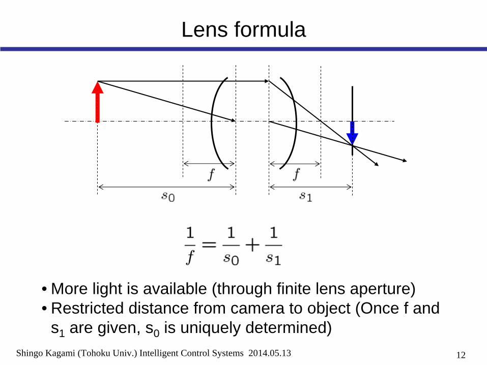
Lens formula
• More light is available (through finite lens aperture)• Restricted distance from camera to object (Once f and
s1 are given, s0 is uniquely determined)

13Shingo Kagami (Tohoku Univ.) Intelligent Control Systems 2014.05.13
Imager size, Aperture size and Focal length
D
f
Aθ
addmissible blur circle
tolerable errors in focal length

14Shingo Kagami (Tohoku Univ.) Intelligent Control Systems 2014.05.13
Outline
• Lens and Optical Parts
• Image Sensors• CCD / CMOS sensors• Integration / Shutter Modes
• In-Camera Image Processing
• Image Data Transfer
• Dynamic Range Enhancement

15Shingo Kagami (Tohoku Univ.) Intelligent Control Systems 2014.05.13
Solid-State Image Sensor
EC Conductive Band
Valence Band
h Electron
Hole
EV
Pixel

16Shingo Kagami (Tohoku Univ.) Intelligent Control Systems 2014.05.13
Minimal Knowledge of Semiconductor Devices
n+ n+
p
SiO2
PolySi
MOS switchWhen VG
is high, S and G are connected (switch on)
GS D
G
S D
R
V1
V2
Source Follower Amp.V2
= V1
+ α
side section view
top view
V
Potential WellBy applying locally high voltage, electronic charges can be collected

17Shingo Kagami (Tohoku Univ.) Intelligent Control Systems 2014.05.13
Photodiode
p
n
h
photocurrent i: proportional to brightness
V > 0 (i.e. inversely biased)
V = 0
An intuitive interpretation:
A Ampere Meter here?

18Shingo Kagami (Tohoku Univ.) Intelligent Control Systems 2014.05.13
What if ampere meter is used
A
• Photocurrent is very weak• order of pA ~ fA• too susceptible to noise
• Difficult to measure millions of pixels at the same time, so time division is mandatory
• for most of the time, photocurrent is just disposed
19Shingo Kagami (Tohoku Univ.) Intelligent Control Systems 2014.05.13
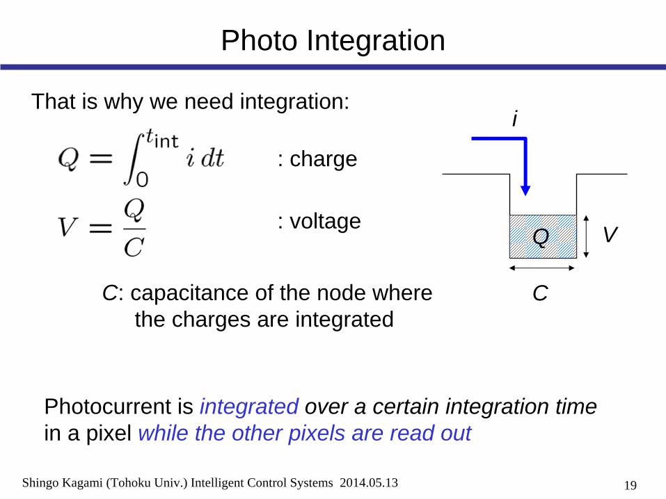
Photo Integration
That is why we need integration:i
Q
C: capacitance of the node where the charges are integrated
V
C
: charge
: voltage
Photocurrent is integrated over a certain integration time in a pixel while the other pixels are read out
20Shingo Kagami (Tohoku Univ.) Intelligent Control Systems 2014.05.13
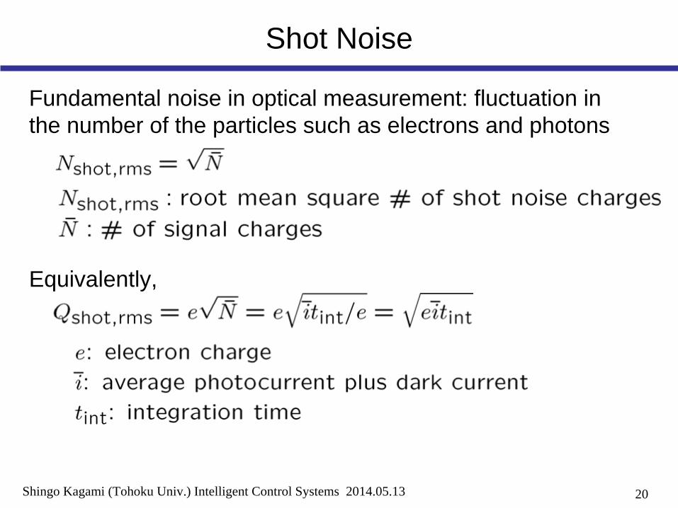
Shot Noise
Fundamental noise in optical measurement: fluctuation in the number of the particles such as electrons and photons
Equivalently,

21Shingo Kagami (Tohoku Univ.) Intelligent Control Systems 2014.05.13
Noise and Integration time
With N times longer tint , signal-to-noise ratio (SNR) is multiplied by:
• with respect to shot noise• with respect to other noise
Vintegration time
signal
shot noise
noise with constant variance(some introduced by integration circuitry)
tint
22Shingo Kagami (Tohoku Univ.) Intelligent Control Systems 2014.05.13
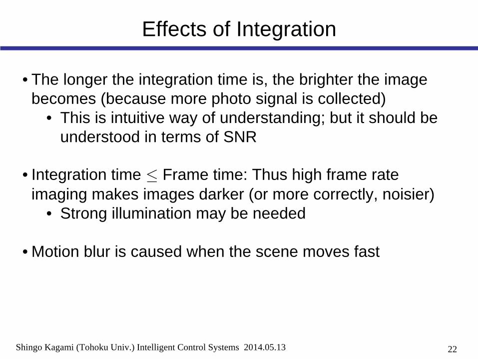
Effects of Integration
• The longer the integration time is, the brighter the image becomes (because more photo signal is collected)
• This is intuitive way of understanding; but it should be understood in terms of SNR
• Integration time ≤
Frame time: Thus high frame rate imaging makes images darker (or more correctly, noisier)
• Strong illumination may be needed
• Motion blur is caused when the scene moves fast

23Shingo Kagami (Tohoku Univ.) Intelligent Control Systems 2014.05.13
Integration-mode photodiode
pn
Ec
electrically floating
Ec
V
grounded
photo-generatedcharges

24Shingo Kagami (Tohoku Univ.) Intelligent Control Systems 2014.05.13
Schematic Description of Integration
C
(A) Reset (B) Integration(A) (B)
ti
VPD
VPD
VDD

25Shingo Kagami (Tohoku Univ.) Intelligent Control Systems 2014.05.13
Potential Description of Integration
VPD
VPD
VPD
0
VDD potential well

26Shingo Kagami (Tohoku Univ.) Intelligent Control Systems 2014.05.13
Outline
• Lens and Optical Parts
• Image Sensors• CCD / CMOS sensors• Integration / Shutter Modes
• In-Camera Image Processing
• Image Data Transfer
• Dynamic Range Enhancement

27Shingo Kagami (Tohoku Univ.) Intelligent Control Systems 2014.05.13
CCD and CMOS image sensors
CCD sensors CMOS sensors
High image quality - high cost Varies from low quality – low costto high quality – high cost
Special fabrication process Standard CMOS process can be used (but special process is also used for high quality)
Large power dissipation(multiple high voltage required)
Low power consumption(single CMOS level voltage)
Difficult to be integrated with computational functionality
Easy to be integrated with CMOS processing circuits

28Shingo Kagami (Tohoku Univ.) Intelligent Control Systems 2014.05.13
CCD and CMOS image sensors
• These terms do not refer to photo detecting structures!• Fundamental difference is “how to readout the signal charge
amount”
h Q VCCD sensor:
within pixel
CMOS sensor: h Q Vwithin pixel
CCD: Charge-Coupled DevicesCMOS: Complementary Metal-Oxide-Semiconductor

29Shingo Kagami (Tohoku Univ.) Intelligent Control Systems 2014.05.13
CCD (Charge-Coupled Device)
p
Ec
Ec
V
PolySi(electrode)V > 0
SiO2 (insulator)
t
V > 0
V > 0 V > 0
V > 0
V > 0 V > 0

30Shingo Kagami (Tohoku Univ.) Intelligent Control Systems 2014.05.13
CCD Image Sensor
Interline Transfer CCD (IT-CCD)
Q
Q
vertical CCD
horizontal CCD Q-V converter
V
31Shingo Kagami (Tohoku Univ.) Intelligent Control Systems 2014.05.13
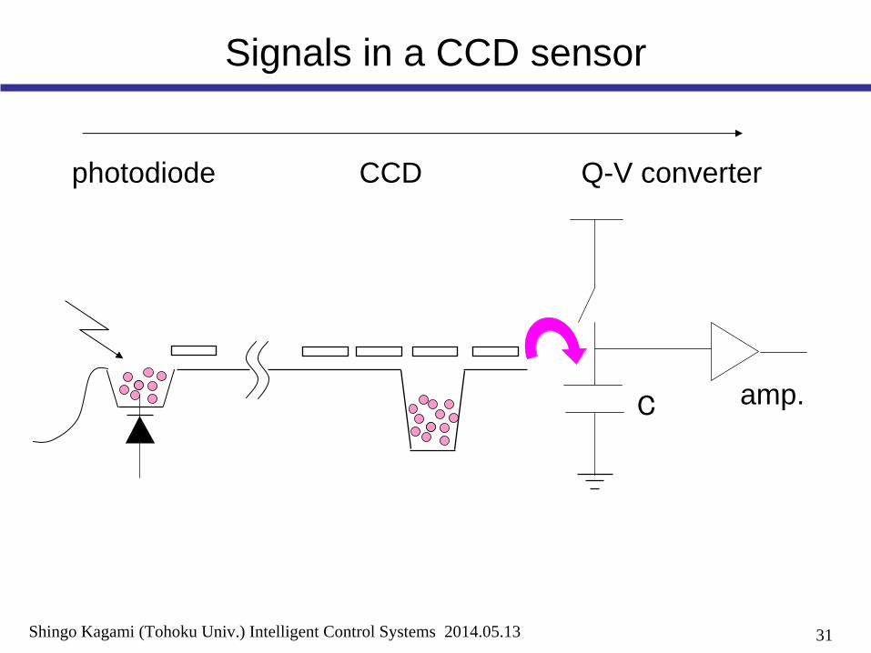
Signals in a CCD sensor
C
photodiode CCD Q-V converter
amp.
32Shingo Kagami (Tohoku Univ.) Intelligent Control Systems 2014.05.13
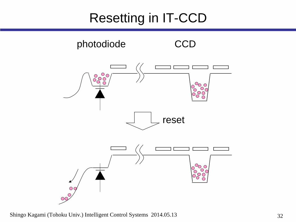
Resetting in IT-CCD
photodiode CCD
reset

33Shingo Kagami (Tohoku Univ.) Intelligent Control Systems 2014.05.13
Electronic Shutters in CCD
IT-CCD (w/o electronic shutter):
read pulse
integrated charge
IT-CCD (with electronic shutter):
read pulse
integrated charge
reset pulse
integration time
integration time

34Shingo Kagami (Tohoku Univ.) Intelligent Control Systems 2014.05.13
CMOS Image Sensor
row selectsignal
column circuit
reset signal
resetswitch
amp
selectswitch
3-transistor Active Pixel Sensor (3T-APS)
output

35Shingo Kagami (Tohoku Univ.) Intelligent Control Systems 2014.05.13
Signals in a CMOS sensor
C
reset switch select switch
reset integration reset
Signal Voltage
t
source follower amp
Vin
Vout
source follower:• Vout
= Vin
+
Vbias

36Shingo Kagami (Tohoku Univ.) Intelligent Control Systems 2014.05.13
Shutter Modes
row1
row2
row3
row3 readout
row1 readoutrow2 readout
row1 integration
row2 integration
row3 integration
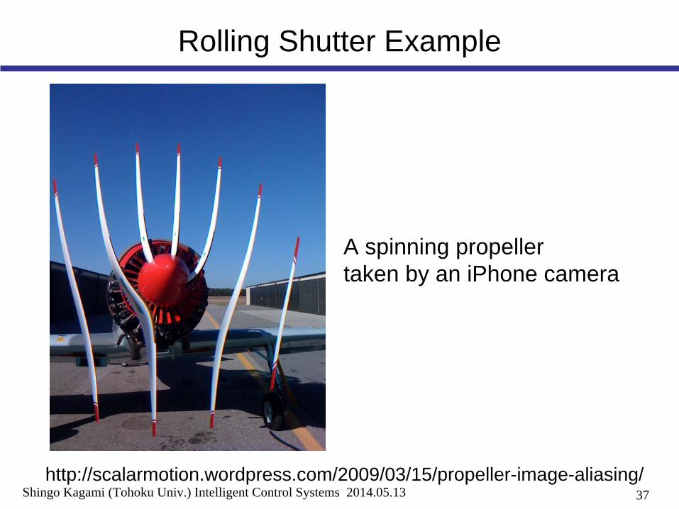
While IT-CCDs operate in the global shutter mode,3T-APS CMOS sensors operate in the rolling shutter mode
37Shingo Kagami (Tohoku Univ.) Intelligent Control Systems 2014.05.13
Rolling Shutter Example
http://scalarmotion.wordpress.com/2009/03/15/propeller-image-aliasing/
A spinning propeller taken by an iPhone camera
38Shingo Kagami (Tohoku Univ.) Intelligent Control Systems 2014.05.13
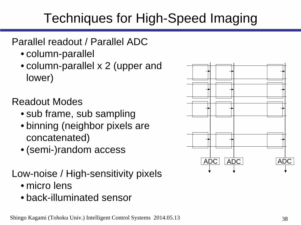
Techniques for High-Speed Imaging
Parallel readout / Parallel ADC• column-parallel• column-parallel x 2 (upper and lower)
Readout Modes• sub frame, sub sampling• binning (neighbor pixels are concatenated)
• (semi-)random access
Low-noise / High-sensitivity pixels• micro lens• back-illuminated sensor
ADC ADC ADC
39Shingo Kagami (Tohoku Univ.) Intelligent Control Systems 2014.05.13
Outline
• Lens and Optical Parts
• Image Sensors• CCD / CMOS sensors• Integration / Shutter Modes
• In-Camera Image Processing
• Image Data Transfer
• Dynamic Range Enhancement

40Shingo Kagami (Tohoku Univ.) Intelligent Control Systems 2014.05.13
In-Camera Processing
imagesensor
A/Dcolor
processing
intensitycurve
correction
datatransfer
may be in the sensor(chip level, or column level)
may be done by softwareafter the image data are transferred

41Shingo Kagami (Tohoku Univ.) Intelligent Control Systems 2014.05.13
Color Processing (demosaicing)
•Can be done by software; but it takes computation time•Can be done in camera; but it consumes 3 times transfer bandwidth

42Shingo Kagami (Tohoku Univ.) Intelligent Control Systems 2014.05.13
Brightness, Contrast, and Gamma
x: spatial position
I: pixel value I
x
I
x
I’
x
I’
x
I’
x
I’ = I + a I’ = k I I’ = I

43Shingo Kagami (Tohoku Univ.) Intelligent Control Systems 2014.05.13
Outline
• Lens and Optical Parts
• Image Sensors• CCD / CMOS sensors• Integration / Shutter Modes
• In-Camera Image Processing
• Image Data Transfer
• Dynamic Range Enhancement

44Shingo Kagami (Tohoku Univ.) Intelligent Control Systems 2014.05.13
Data Transfer
8 [bits/pixel] ×
1 M [pixels/frame] ×
30 [fps] = 240 M [bps]
8 [bits/pixel] ×
1 M [pixels/frame] ×
1000 [fps] = 8000 M [bps]
interface max. bit rate
IEEE 1394a 400 MbpsIEEE 1394b 800 MbpsUSB 2.0 480 MbpsUSB 3.0 5000 MbpsGigabit Ethernet 1000 MbpsPCI Express 3.0 8000 Mbps / laneCamera Link 2000 Mbps (base config.)
5440 Mbps (full config.)and more (extended config.)

45Shingo Kagami (Tohoku Univ.) Intelligent Control Systems 2014.05.13
Outline
• Lens and Optical Parts
• Image Sensors• CCD / CMOS sensors• Integration / Shutter Modes
• In-Camera Image Processing
• Image Data Transfer
• Dynamic Range Enhancement

46Shingo Kagami (Tohoku Univ.) Intelligent Control Systems 2014.05.13
Dynamic Range
lower
upper log 20[dB] DRii
noise levelt
V
integration time
saturation level

47Shingo Kagami (Tohoku Univ.) Intelligent Control Systems 2014.05.13
Dynamic range and Integration time
t
V
integration time
Simply modifying the integration time will not contribute to dynamic range enhancement.
Commonly used techniques utilize multiple integration times.
48Shingo Kagami (Tohoku Univ.) Intelligent Control Systems 2014.05.13
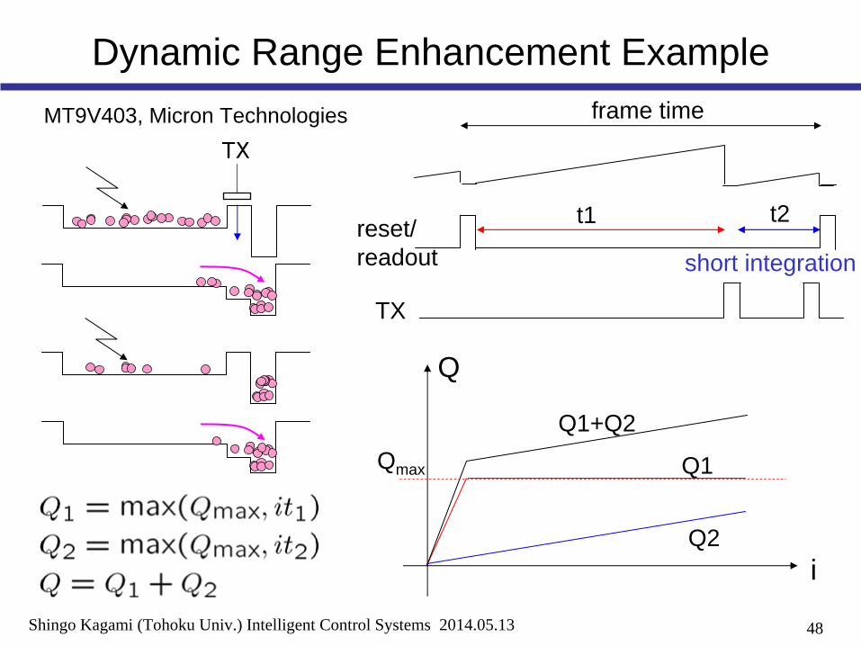
Dynamic Range Enhancement Example
TX
frame time
reset/readout
TX
t1 t2
i
Q
Q1+Q2
Q1
Q2
MT9V403, Micron Technologies
Qmax
short integration
49Shingo Kagami (Tohoku Univ.) Intelligent Control Systems 2014.05.13
References
Textbooks on Cameras and Image Sensors:• A. Hornberg eds.: Handbook of Machine Vision, Wiley-VCH, 2006. • R. Szeliski: Computer Vision: Algorithms and Applications, Springer, 2010. • J. Ohta: Smart CMOS Image Sensors and Applications, CRC Press, 2007.• E. Hecht: Optics, Pearson Education, 2002.
(in Japanese)• 米本 和也: CCD/CMOSイメージ・センサの基礎と応用, CQ出版社, 2003.• 相澤 清晴, 浜本 隆之 (編著): CMOSイメージセンサ, コロナ社, 2012.• 黒田 隆男: イメージセンサの本質と基礎, コロナ社, 2012.• ディジタル画像処理編集委員会, ディジタル画像処理, CG-ARTS協会, 2004.