call flow cs
TRANSCRIPT
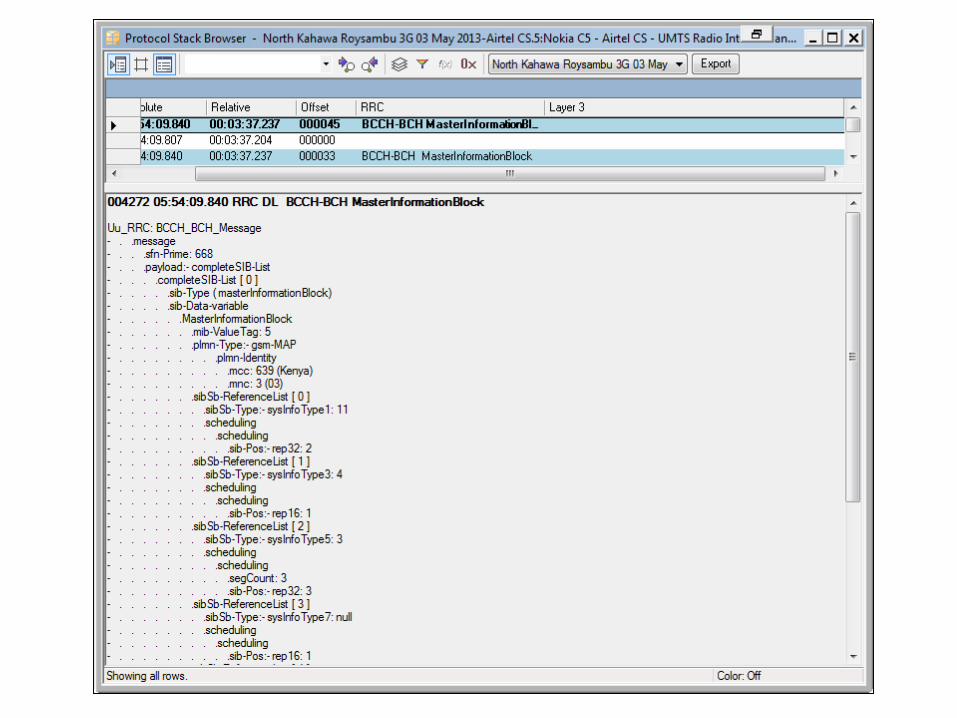

System Information Message• BCCH contains the System Information message• Message is sent using Transparent mode RLC• BCH is always interleaved over a 20 ms TTI• SFN Prime is the SFN of the first 10 ms radio frame• The actual value of SFN Prime is 2 x IE i.e. 2 x 668 in
this example• This System Information message includes the MIB,
SIB1, SIB3,SIB5 and SIB7• The UE extracts the MIB and each of the SIBs and
decodes each separately• The contents of the BCH varies from one system
information message to the next i.e. whether or not a MIB and SB are included and which SIBs are included
• Scheduling of the SIBs is completed by the RNC but indicated to the UE using Information Elements (IE) within the MIB and SB
• SIBs may be segmented and broadcast in multiple System Information messages


• The Master Information Block (MIB) is broadcast once every 8 radio frames (3GPP specified)
• The MIB has a SIB_POS = 0 and a SIB_OFF = 2 frames (offset is only applicable when the MIB requires multiple segments)
• The MIB includes the MIB value tag which has a range from 1 to 8. The value tag indicates when the MIB contents have changed
• The network type is specified as being GSM-MAP with an MCC of 639 and an MNC of 3.
• The SIB reference list specifies scheduling information for SIB 1,SIB 3, SIB 5 and SIB 7.
• The SIBs which aren’t scheduled within the MIB are scheduled within Scheduling Block
• SIB 1 scheduling information:• Value tag of 11• repetition every 32 frames• position is frame 4 (actual value = IE x 2)
Master Information Block (MIB)
•Value tag isn’t applicable as SIB 7 contains data which can change in every message•Similarly for other SIBs
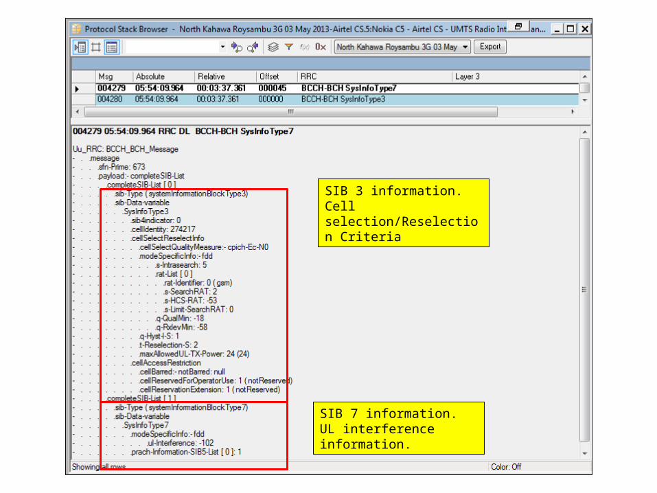
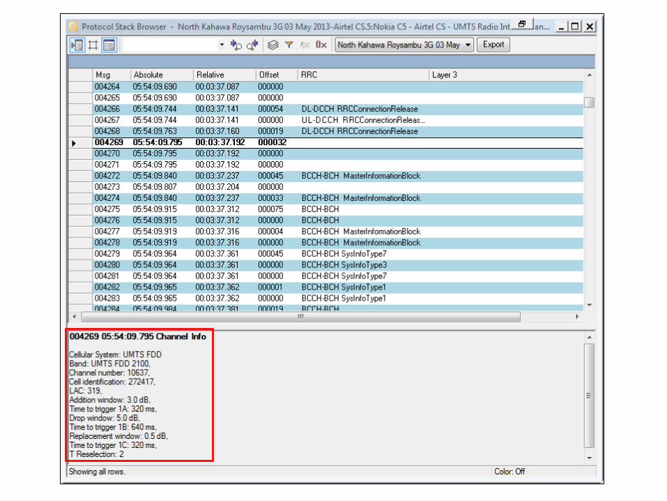
SIB 3 information. Cell selection/Reselection Criteria
SIB 7 information. UL interference information.
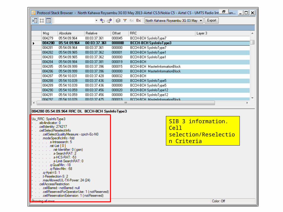
SIB 3 information. Cell selection/Reselection Criteria
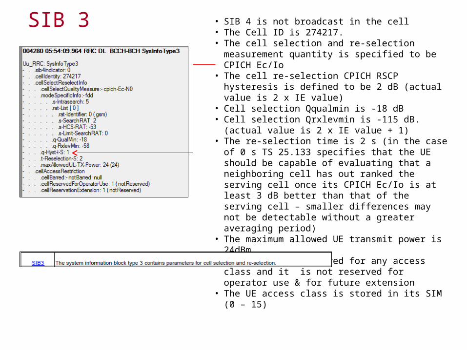
SIB 3 • SIB 4 is not broadcast in the cell• The Cell ID is 274217.• The cell selection and re-selection measurement
quantity is specified to be CPICH Ec/Io• The cell re-selection CPICH RSCP hysteresis is
defined to be 2 dB (actual value is 2 x IE value)• Cell selection Qqualmin is -18 dB• Cell selection Qrxlevmin is -115 dB. (actual value is 2 x
IE value + 1)• The re-selection time is 2 s (in the case of 0 s TS
25.133 specifies that the UE should be capable of evaluating that a neighboring cell has out ranked the serving cell once its CPICH Ec/Io is at least 3 dB better than that of the serving cell – smaller differences may not be detectable without a greater averaging period)
• The maximum allowed UE transmit power is 24dBm• The cell is not barred for any access class and it is not
reserved for operator use & for future extension• The UE access class is stored in its SIM (0 – 15)
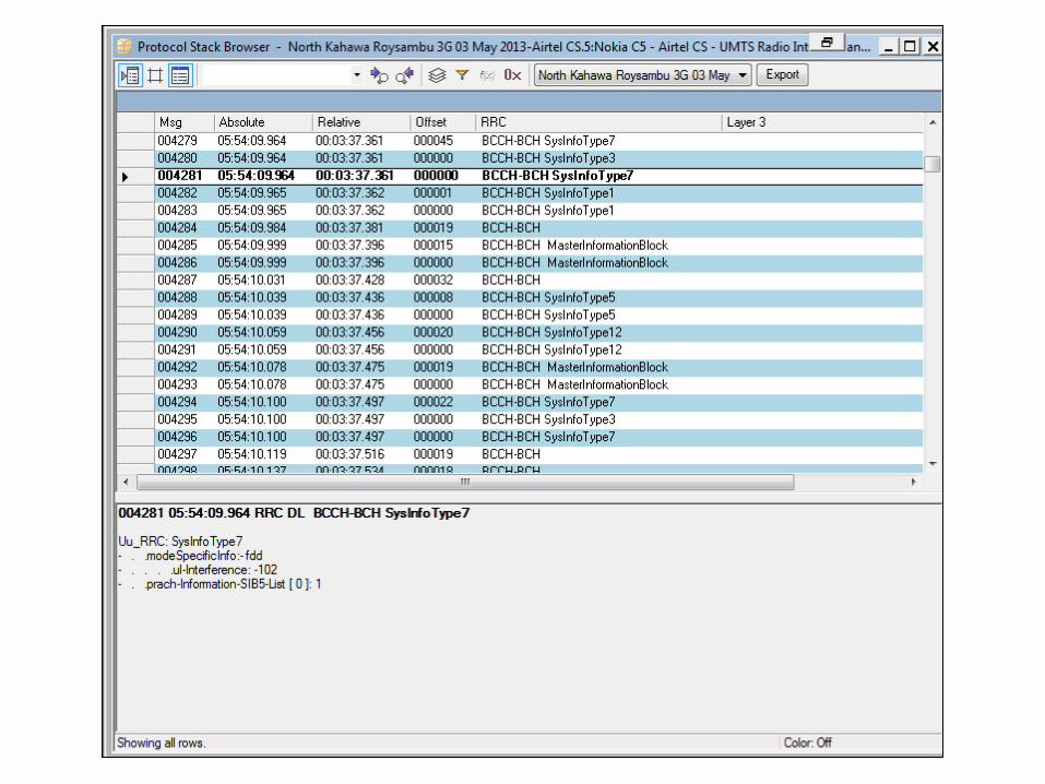

SIB 7
• The uplink RSSI as measured at the output of the receiver’s root raised cosine filter within the WTR(Wide Temperature Range) is –102 dBm
• The PRACH dynamic persistance is defined as 1. This value is fed into the equation 2^-(N-1) = 2^0 = 1

SIB 1(I)
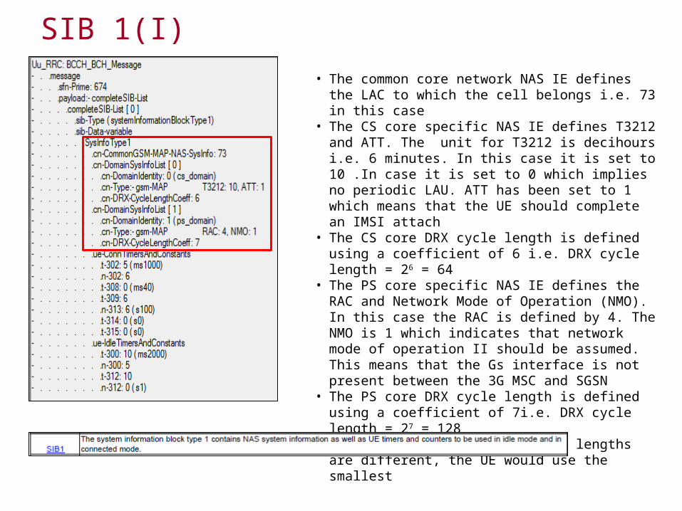
• The common core network NAS IE defines the LAC to which the cell belongs i.e. 73 in this case
• The CS core specific NAS IE defines T3212 and ATT. The unit for T3212 is decihours i.e. 6 minutes. In this case it is set to 10 .In case it is set to 0 which implies no periodic LAU. ATT has been set to 1 which means that the UE should complete an IMSI attach
• The CS core DRX cycle length is defined using a coefficient of 6 i.e. DRX cycle length = 26 = 64
• The PS core specific NAS IE defines the RAC and Network Mode of Operation (NMO). In this case the RAC is defined by 4. The NMO is 1 which indicates that network mode of operation II should be assumed. This means that the Gs interface is not present between the 3G MSC and SGSN
• The PS core DRX cycle length is defined using a coefficient of 7i.e. DRX cycle length = 27 = 128
• In this case the two DRX cycle lengths are different, the UE would use the smallest
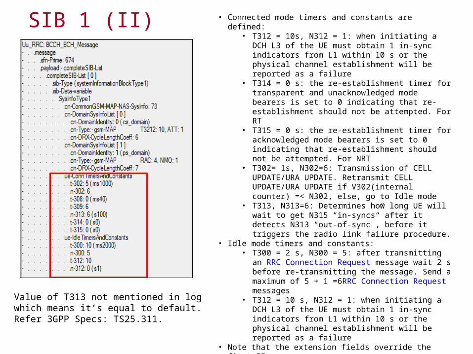
SIB 1 (II) • Connected mode timers and constants are defined:• T312 = 10s, N312 = 1: when initiating a DCH L3 of the
UE must obtain 1 in-sync indicators from L1 within 10 s or the physical channel establishment will be reported as a failure
• T314 = 0 s: the re-establishment timer for transparent and unacknowledged mode bearers is set to 0 indicating that re-establishment should not be attempted. For RT
• T315 = 0 s: the re-establishment timer for acknowledged mode bearers is set to 0 indicating that re-establishment should not be attempted. For NRT
• T302= 1s, N302=6: Transmission of CELL UPDATE/URA UPDATE. Retransmit CELL UPDATE/URA UPDATE if V302(internal counter) =< N302, else, go to Idle mode
• T313, N313=6: Determines how long UE will wait to get N315 “in-syncs” after it detects N313 “out-of-sync”, before it triggers the radio link failure procedure.
• Idle mode timers and constants:• T300 = 2 s, N300 = 5: after transmitting an RRC
Connection Request message wait 2 s before re-transmitting the message. Send a maximum of 5 + 1 =6RRC Connection Request messages
• T312 = 10 s, N312 = 1: when initiating a DCH L3 of the UE must obtain 1 in-sync indicators from L1 within 10 s or the physical channel establishment will be reported as a failure
• Note that the extension fields override the first IEs
Value of T313 not mentioned in log which means it’s equal to default. Refer 3GPP Specs: TS25.311.


• SIB 6 is not broadcast in the cell• The PICH is transmitted with a power 7 dB less than
that of the CPICH• The AICH is transmitted with a power 6 dB less than
that of the CPICH• PRACH signature 65535 can be used within the cell
(this represents 16 out of a possible 16)• The PRACH spreading factor is 64• PRACH scrambling code 0 should be used (there are
16 PRACH scrambling codes associated with each primary scrambling code)
• The PRACH puncturing limit is 1 i.e. puncturing is not allowed
• PRACH sub-channels 4095 can be used i.e. all sub-channels
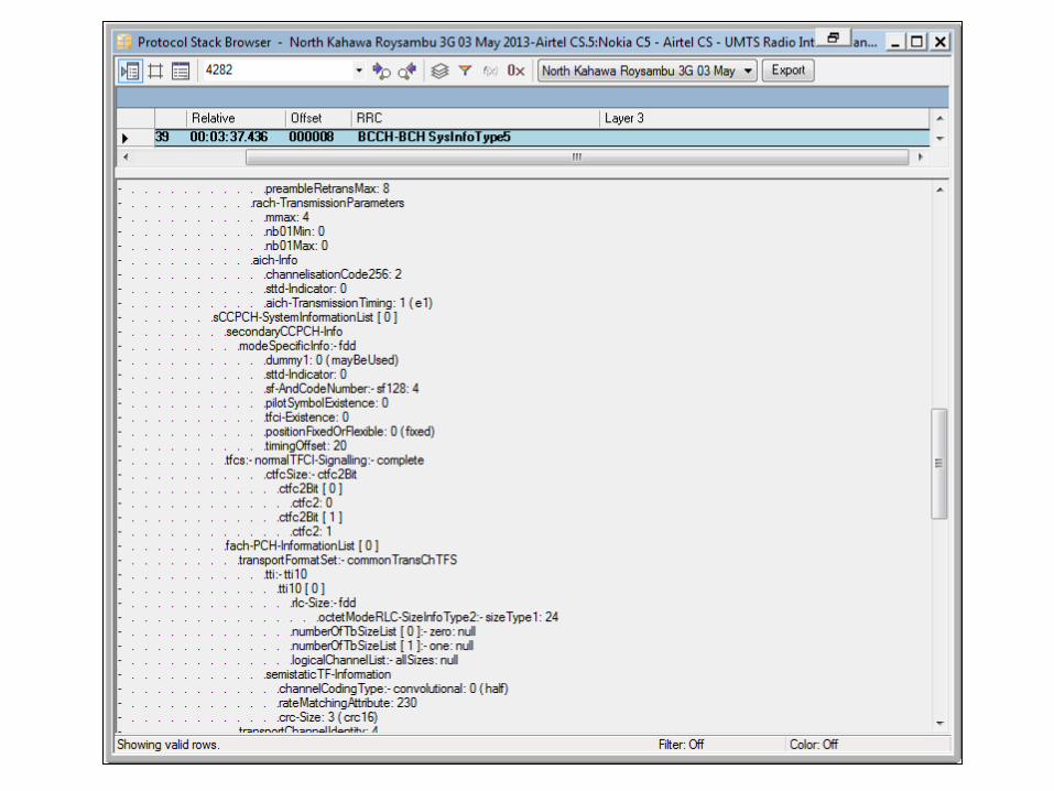
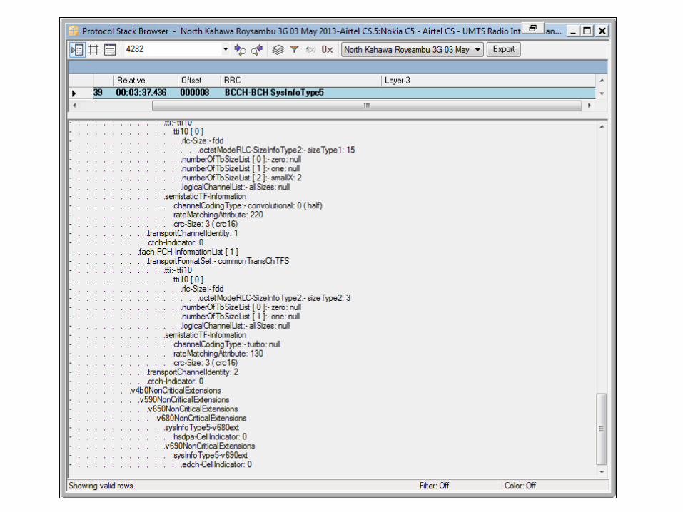
SIB 5 (I)
SIB 5 (II)
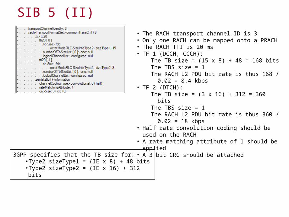
• The RACH transport channel ID is 3• Only one RACH can be mapped onto a PRACH• The RACH TTI is 20 ms• TF 1 (DCCH, CCCH):
The TB size = (15 x 8) + 48 = 168 bitsThe TBS size = 1The RACH L2 PDU bit rate is thus 168 / 0.02 = 8.4
kbps• TF 2 (DTCH):
The TB size = (3 x 16) + 312 = 360 bitsThe TBS size = 1The RACH L2 PDU bit rate is thus 360 / 0.02 = 18
kbps• Half rate convolution coding should be used on the
RACH• A rate matching attribute of 1 should be applied• A 3 bit CRC should be attached
3GPP specifies that the TB size for:• Type2 sizeType1 = (IE x 8) + 48 bits• Type2 sizeType2 = (IE x 16) + 312 bits
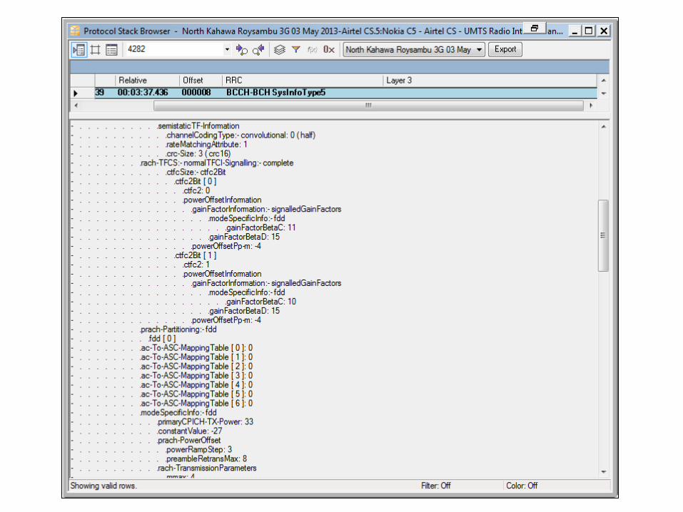
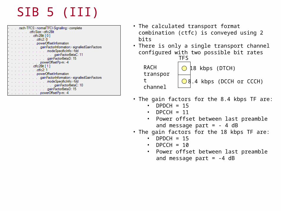
SIB 5 (III)• The calculated transport format combination (ctfc) is
conveyed using 2 bits• There is only a single transport channel configured with
two possible bit rates
8.4 kbps (DCCH or CCCH)
18 kbps (DTCH)RACH transport channel
TFS
• The gain factors for the 8.4 kbps TF are:• DPDCH = 15• DPCCH = 11• Power offset between last preamble and
message part = - 4 dB• The gain factors for the 18 kbps TF are:
• DPDCH = 15• DPCCH = 10• Power offset between last preamble and
message part = -4 dB