calibrating and operating coriolis flowmeters with respect ... · calibration procedure –reynolds...
TRANSCRIPT

Calibrating and operating Coriolis flowmeters with respect to temperature, pressure, viscosity and
Reynolds number Effects
Chris Mills, NEL

– BACKGROUND
– UK REGULATIONS / ISO 10790
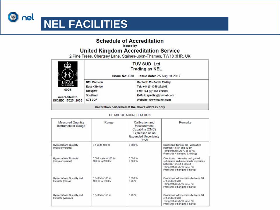
– NEL FACILITIES
– EXPERIENCES
– NEL RECOMMENDATIONS
CONTENTS
Brief history
BACKGROUND
• 2006 - 2010: NEL completed research with Coriolis meters across
laminar – turbulent regimes with viscous oils and discovered
Reynolds Number effect
• 2011: NEL completed research with Coriolis meters for a number of
O&G operators at elevated temperatures.
• 2012: NEL formulated a Joint Industrial Project (JIP) exploring
influence of T, P, and viscosity.
• 2014: JIP completed and concluded that:
– calibration under conditions similar to the field required
– lack of traceable calibration facilities that can operate at elevated
temperature, pressure, and viscosity
• 2014 – 2016 NEL designed & built a new flow loop operating at
Elevated P and T (EPAT) & fully accredited to UKAS
• 2016 - present: This presentation focus now on NEL experiences
and ‘Calibrating and operating Coriolis flowmeters’

Current regulations
• UK Oil & Gas Authority (OGA) Guidelines
UK REGULATIONS

What about the Coriolis ISO Standard?
ISO 10790:2015

What about the Coriolis ISO Standard?
ISO 10790:2015

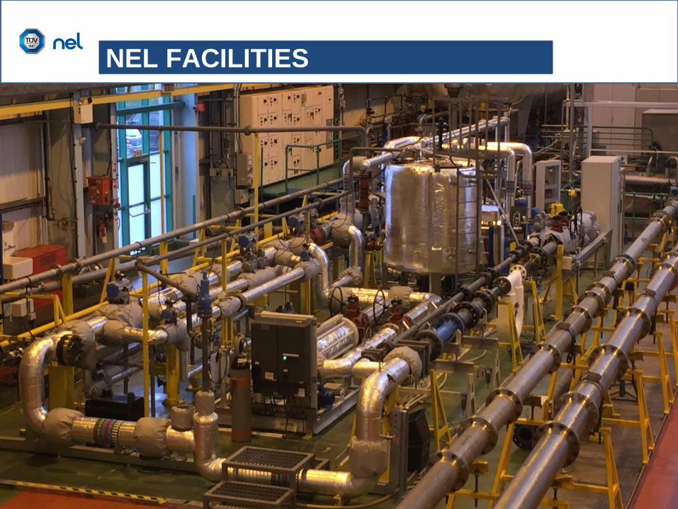
Elevated Pressure & Temperature (EPAT) Facility
NEL FACILITIES
NEL FACILITIES
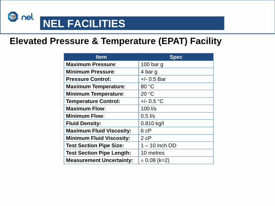
Elevated Pressure & Temperature (EPAT) Facility
Item Spec
Maximum Pressure: 100 bar g
Minimum Pressure: 4 bar g
Pressure Control: +/- 0.5 Bar
Maximum Temperature: 80 °C
Minimum Temperature: 20 °C
Temperature Control: +/- 0.5 °C
Maximum Flow: 100 l/s
Minimum Flow: 0.5 l/s
Fluid Density: 0.810 kg/l
Maximum Fluid Viscosity: 6 cP
Minimum Fluid Viscosity: 2 cP
Test Section Pipe Size: 1 – 10 inch OD
Test Section Pipe Length: 10 metres
Measurement Uncertainty: ± 0.08 (k=2)
NEL FACILITIES
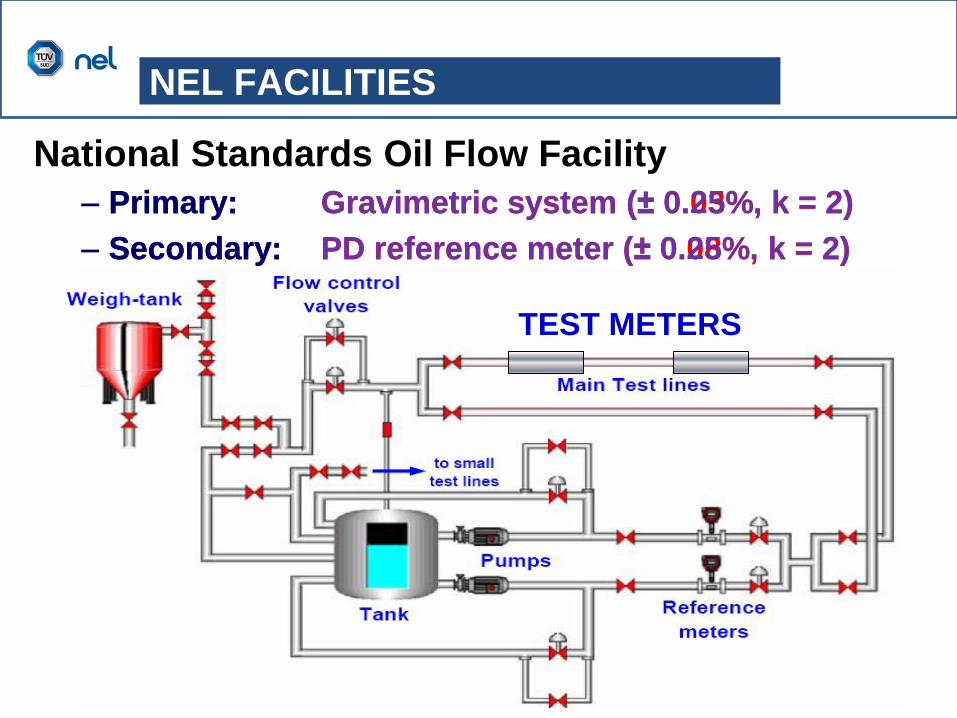
National Standards Oil Flow Facility
– Primary: Gravimetric system (± 0.03%, k = 2)
– Secondary: PD reference meter (± 0.08%, k = 2)
TEST METERS
– Primary: Gravimetric system (± 0.25%, k = 2)
– Secondary: PD reference meter (± 0.25%, k = 2)
NEL FACILITIES

Item Spec
Maximum Pressure: 6 bar g
Pressure Control: +/- 0.2 Bar
Maximum Temperature: 50 °C
Minimum Temperature: 5 °C
Temperature Control: +/- 0.5 °C
Maximum Flow: 200 l/s
Minimum Flow: 0.04 l/s
Fluid Density: 0.750 – 0.890 kg/l
Maximum Fluid Viscosity: 2000 cP
Minimum Fluid Viscosity: 1 cP
Test Section Pipe Size: 1 – 12 inch OD
Test Section Pipe Length: 20 metres
NEL FACILITIES
National Standards Oil Flow Facility
NEL FACILITIES
EXPERIENCE
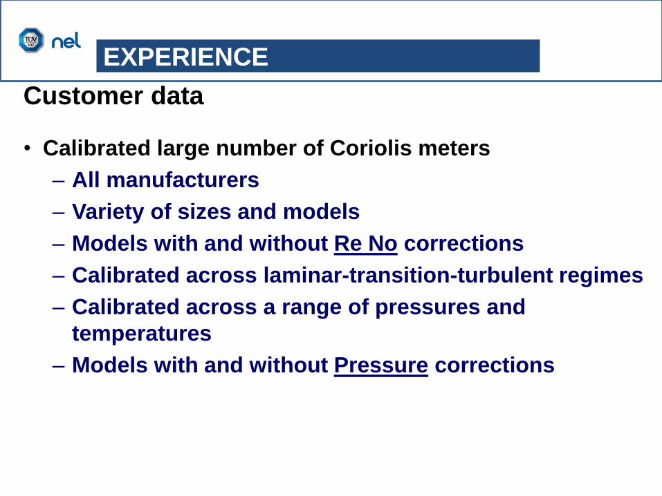
Customer data
• Calibrated large number of Coriolis meters
– All manufacturers
– Variety of sizes and models
– Models with and without Re No corrections
– Calibrated across laminar-transition-turbulent regimes
– Calibrated across a range of pressures and
temperatures
– Models with and without Pressure corrections

EXPERIENCE
Temperature & Pressure
-0.80
-0.70
-0.60
-0.50
-0.40
-0.30
-0.20
-0.10
0.00
0 50 100 150 200 250 300 350
%E
rr (R
ef.
Ma
ss
)
Ref. Mass Flow, T/hr
Kerosene 20degC 3cSt Gas Oil 20degC 8cSt Gas Oil 20degC 8cSt (R)

-2.00
-1.75
-1.50
-1.25
-1.00
-0.75
-0.50
-0.25
0.00
0 50 100 150 200 250 300 350
%E
rr (R
ef.
Ma
ss
)
Ref. Mass Flow, T/hr
Kerosene 20degC 3cSt Gas Oil 20degC 8cSt Gas Oil 20degC 8cSt (R) EPAT 25degC 10bar.g
EPAT25degC 20bar.g EPAT 25degC 20bar.g R EPAT 25degC 40bar.g
EXPERIENCE
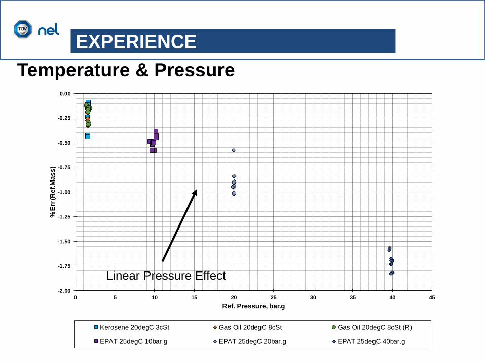
Temperature & Pressure
EXPERIENCE
Temperature & Pressure
-2.00
-1.75
-1.50
-1.25
-1.00
-0.75
-0.50
-0.25
0.00
0 5 10 15 20 25 30 35 40 45
%E
rr (R
ef.
Ma
ss
)
Ref. Pressure, bar.g
Kerosene 20degC 3cSt Gas Oil 20degC 8cSt Gas Oil 20degC 8cSt (R)
EPAT 25degC 10bar.g EPAT 25degC 20bar.g EPAT 25degC 40bar.g
Linear Pressure Effect

EXPERIENCE
Customer data
Linear Pressure Effect
NEL RECOMMENDATION
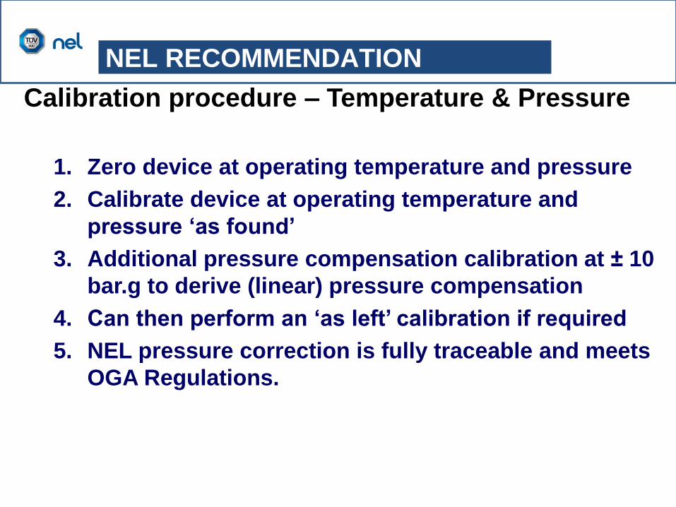
Calibration procedure – Temperature & Pressure
1. Zero device at operating temperature and pressure
2. Calibrate device at operating temperature and
pressure ‘as found’
3. Additional pressure compensation calibration at ± 10
bar.g to derive (linear) pressure compensation
4. Can then perform an ‘as left’ calibration if required
5. NEL pressure correction is fully traceable and meets
OGA Regulations.
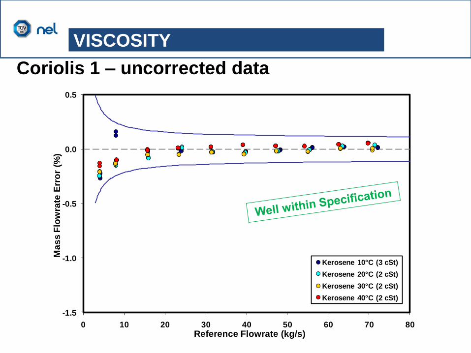
-1.5
-1.0
-0.5
0.0
0.5
0 10 20 30 40 50 60 70 80
Ma
ss
Flo
wra
te E
rro
r (%
)
Reference Flowrate (kg/s)
Kerosene 10°C (3 cSt)
Kerosene 20°C (2 cSt)
Kerosene 30°C (2 cSt)
Kerosene 40°C (2 cSt)
Coriolis 1 – uncorrected data
VISCOSITY
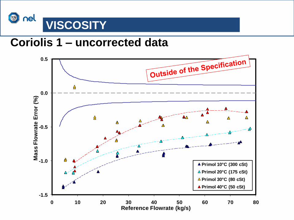
-1.5
-1.0
-0.5
0.0
0.5
0 10 20 30 40 50 60 70 80
Ma
ss
Flo
wra
te E
rro
r (%
)
Reference Flowrate (kg/s)
Primol 10°C (300 cSt)
Primol 20°C (175 cSt)
Primol 30°C (80 cSt)
Primol 40°C (50 cSt)
Coriolis 1 – uncorrected data
VISCOSITY
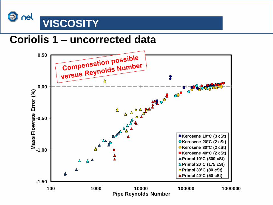
-1.50
-1.00
-0.50
0.00
0.50
100 1000 10000 100000 1000000
Ma
ss
Flo
wra
te E
rro
r (%
)
Pipe Reynolds Number
Kerosene 10°C (3 cSt)
Kerosene 20°C (2 cSt)
Kerosene 30°C (2 cSt)
Kerosene 40°C (2 cSt)
Primol 10°C (300 cSt)
Primol 20°C (175 cSt)
Primol 30°C (80 cSt)
Primol 40°C (50 cSt)
Coriolis 1 – uncorrected data
VISCOSITY

Coriolis 2 – No ‘Re No correction’ data
-1.50
-1.25
-1.00
-0.75
-0.50
-0.25
0.00
0.25
0.50
0.75
1.00
1.25
1.50
0 20 40 60 80 100
Ma
ss
Flo
w E
rro
r [%
]
Ref. Mass Flow [kg/s]
600 cSt
1000 cSt
VISCOSITY

-1.50
-1.25
-1.00
-0.75
-0.50
-0.25
0.00
0.25
0.50
0.75
1.00
1.25
1.50
10 100 1000 10000
Ma
ss
Flo
w E
rro
r [%
]
Reynolds Number
All Data
VISCOSITY
Coriolis X – No ‘Re No correction’ data
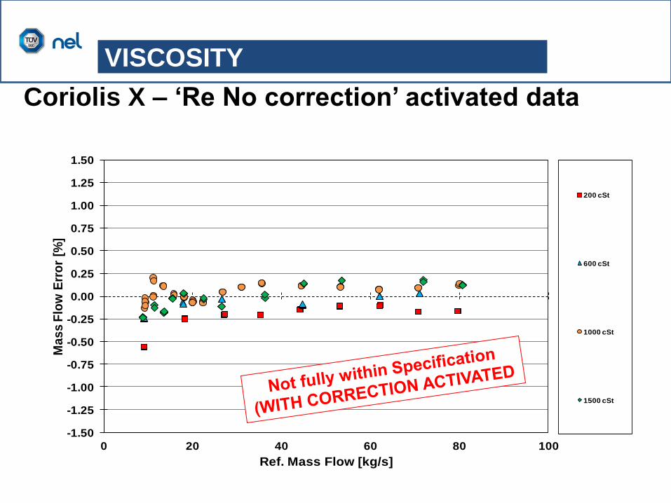
-1.50
-1.25
-1.00
-0.75
-0.50
-0.25
0.00
0.25
0.50
0.75
1.00
1.25
1.50
0 20 40 60 80 100
Ma
ss
Flo
w E
rro
r [%
]
Ref. Mass Flow [kg/s]
200 cSt
600 cSt
1000 cSt
1500 cSt
VISCOSITY
Coriolis X – ‘Re No correction’ activated data

Calibration procedure – Reynolds Number
1. Specify Re No range of device
2. Match Re No range with high viscosity fluid at two or
more temperatures
3. Zero device at operating temperature / and pressure
4. Calibrate device across Re No range ‘as found’
5. Decide if Reynolds Number effect is significant
6. Can then perform an ‘as left’ calibration if required
7. Calibration is fully traceable and meets OGA
Regulations
NEL RECOMMENDATION

– Meters can be zeroed at T&P but as T drops, P drops
significantly.
– High viscosity gravimetric calibrations are time
consuming. Master Meter has higher uncertainty
– RTD on board Coriolis flowmeters measures tube
temperature as opposed to fluid temperature (response
lag)
– If zeroing at elevated temperature, it is important to
allow time for stabilising
– Zero value can change by end of calibration. Possibly
due to expansion / contraction of facility with T&P over
time.
EXPERIENCE

Key findings
– A Coriolis meter water calibration cannot replicate service
conditions and still attain 0.1% meter specification.
– Vendor published pressure corrections are not traceable at
present. Can over (or under) correct for pressure.
– Temperature effect is magnitude less than pressure. NOTE:
Ambient temperature effects can be significant
– Coriolis meters should not be calibrated at ambient
conditions and then deployed to elevated service
conditions.
– They should be calibrated close to service conditions and
characterised against Re No if high viscosity.
– The performance of Coriolis meters from one vendor to
another are not necessarily similar as there are many other
variables.
CONCLUSIONS

DDAT (NEL Database)
– Collating all calibrations (both master meters &
customer)
– Publish the data at conferences and journal papers
– Use customer data to revise Coriolis ISO 10790
FUTURE DEVELOPMENTS
