calfrac well services: shale fracturing operations ...oilproduction.net/files/calfrac.pdf ·...
TRANSCRIPT

Alberto Bertolini Director General, Latin AmericaGary Rokosh VP, Sales, Mkting & Engineering, Cdn DivisionBernie Schulmeister Manager, Laboratory Services
Calfrac Well Services:Shale Fracturing Operations,
Technical Expertise &Achievements

Introduction to Calfrac
Shale Experience in North America
Technology and Engineering
Other Calfrac Efficiencies
Industry Challenges
Horn River Shale Project
Plan for Growth in Argentina
Discussion
Overview

Industry-leading pressure pumping company Fracturing, Coiled Tubing, Nitrogen, Cementing Services Presence in Canada, United States, Russia, Latin America Focused on Technology
R & D facilities / Proprietary chemistries and processes Key Elements of Execution
Safety is priority number one Service quality excellence Secure supply of materials
Awarded Shell’s “2009 Supplier of the Year for the Americas”
Calfrac Well Services

Emphasis on 12 Life Saving Rules
We stress “Consequence Management” We address more than the circumstances; we change the culture
to prevent repetition (behavior-based) We encourage operators to actively participate in HSE programs
We value our association with safety-conscious operators
Calfrac’s HSE Culture

5
Cementing 2%Coiled Tubing 6%
Fracturing 92%
Pressure Pumping Focus Revenue by Service Line – 2011
Fracturing has been and will continue to be our focus
Fracturing is the key technology to facilitate unconventional development
Fracturing has evolved from being 10-15% of the well cost to between 30-50% of the well cost in many unconventional wells
Coiled tubing and cementing have been entry points into other international markets

66
MEXICO
ARGENTINA
RUSSIA
Latin America Equipment Fleet:
5 fracturing spreads totaling 100,000 horsepower
10 cementing crews 2 coiled tubing crews
Russia Equipment Fleet:
5 fracturing spreads totaling 45,000 horsepower
7 deep coiled tubing crews
Worldwide Operations – Exit 2012
UNITED STATES
CANADA
United StatesEquipment Fleet:
15 fracturing spreads totaling490,000 horsepower
14 cementing crews 4 coiled tubing crew
CanadaEquipment Fleet:
17 fracturing spreads totaling400,000 horsepower
21 coiled tubing crews
COLOMBIA

NORTH DAKOTA
COLORADO
OKLAHOMA
ARKANSAS
TEXAS
W. VIRGINIA
PENNSYLVANIA
Horn RiverHorn River
Deep BasinDeep Basin
Lower Lower ShaunavonShaunavon
BakkenBakken
VikingViking
CardiumCardium
DunvernayDunvernay
MontneyMontneyALBERTA
Fort Nelson
Dawson Creek
Grande Prairie
EdsonRed Deer
CalgaryMedicine Hat
EstevanWilliston
JonahJonahGreen RiverGreen River
UintahUintah
PiceancePiceance
NiobraraNiobraraDenverDenver‐‐JulesburgJulesburg
Grand JunctionDenverPlatteville
BeebeGranite WashGranite Wash
PermianPermian
Eagle FordEagle FordBarnettBarnett
HaynesvilleHaynesville
FayettevilleFayetteville
PhillipsburgSmithfield
UticaUtica
MarcellusMarcellus
Unconventional Experience in N.A.
8
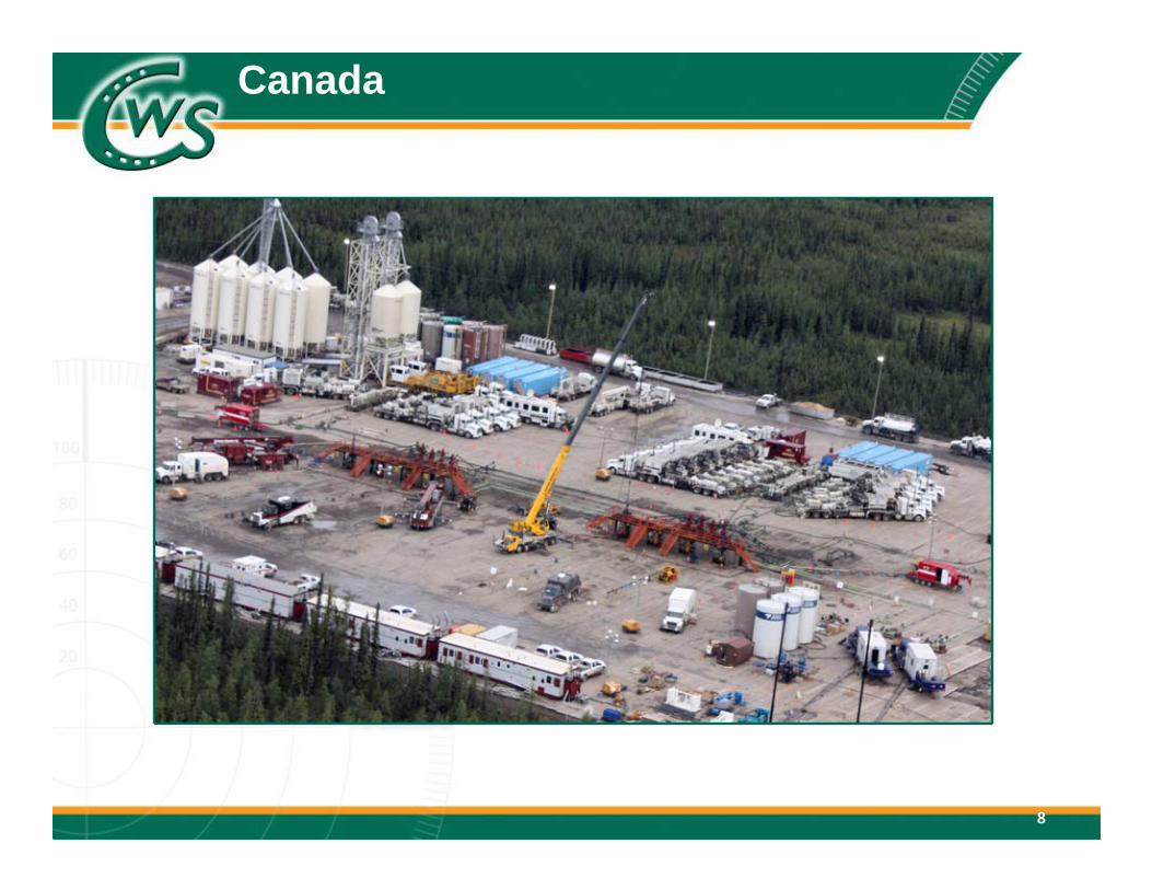
Canada

DuvernayCrew Size: 30,000‐40,000HP# Fracs/Well: 8‐12Stage size: 100 – 200 tonnes
9
British Columbia
Horn River
MontneyDawson Creek
Fort Nelson
Deep Basin Crew size: 12,000‐25,000 HP # Fracs/Well: 3‐7 Stage size: 80‐200 tonnes
Montney Crew size: 15,000‐30,000 HP # Fracs/Well: 5‐13 Stage size: 100‐200 tonnes
Calfrac district officeMajor basin/unconventional play
Horn River Crew size: 40,000‐50,000 HP # Fracs/well: 14‐20 Stage size: 200‐300 tonnes
Red Deer
Alberta
Deep Basin
Edson
Grande Prairie
Duvernay
Natural Gas Resource Plays at a Glance
Western Canada

10
Sask.
British Columbia
Bakken
Red Deer
Edson
CalgaryLower
Shaunavon
Viking
Cardium
Estevan
Calfrac regional/district officeMajor basin/unconventional play
Cardium Crew size: 8,000‐20,000 HP # Fracs/Well: 8‐20 Stage size: 20‐30 tonnes
Lower Shaunavon Crew size: 7,000‐12,000 HP # Fracs/Well: 12‐16 Stage size: 20‐40 tonnes
Viking Crew size: 6,000‐9,000 HP # Fracs/Well: 12‐16 Stage size: 20‐40 tonnes
Bakken Crew size: 4,000‐6,000 HP # Fracs/Well: 15‐20 Stage size: 6‐12 tonnes
Alberta
Alberta BakkenAlberta Bakken Crew size: 4,000‐15,000 HP # Fracs/Well: 12‐20 Stage size: 20‐30 tonnes
MedicineHat
12
Crude Oil Resource Plays at a Glance
Western Canada

11
United States

12
Arkansas
Wyoming
DenverGrand Junction
Beebe
ColoradoW. Virginia
Pennsylvania
Smithfield
Fayetteville
Haynesville
Eagleford
Woodford
Oklahoma
MarcellusPlatteville
Green RiverUtahUintah
Jonah
Piceance
Denver‐Julesburg
Texas
Niobrara
Calfrac regional/district officeMajor basin/unconventional playCalfrac service area
PermianGranite Wash
Barnett
North DakotaBakken
DenverGrand Junction
Platteville
Jonah
Piceance
Denver‐Julesburg
Niobrara
Beebe
Fayetteville
Haynesville
Barnett
Woodford SmithfieldMarcellus
Bakken
Fayetteville• 2 Fracturing Spreads totalling
85,000 horsepower• 5 Cementing Crews
Marcellus• 3 Fracturing Spreads totalling
140,000 horsepower• 4 Cementing Crews
Williston
Williston
Rockies• 3 Fracturing Spreads totalling
80,000 horsepower
Bakken• 4 Fracturing Spreads totalling
100,000 horsepower• 1 Coiled Tubing Crew
United States - Operations

13
Russia
14
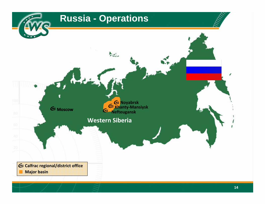
Calfrac regional/district officeMajor basin
Moscow
14
Moscow
Western Siberia
NoyabrskKhanty‐Mansiysk
Calfrac regional/district officeMajor basin
Nefteugansk
Russia - Operations
15
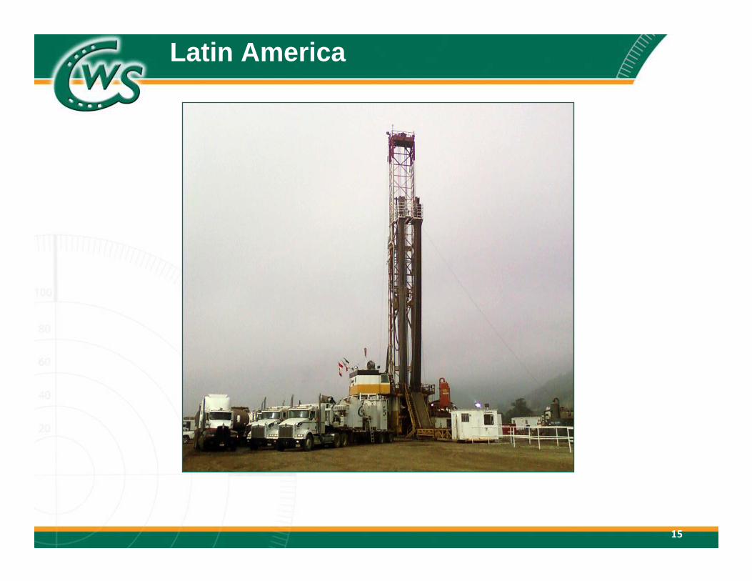
Latin America

16
Calfrac regional/district office
16
Buenos Aires
Catriel
BogotaYopal
Mexico City
Poza Rica
Reynosa
Neuquen
Latin America - Operations

17
Mexico H2 2010 severely impacted by Pemex budgetary constraints. Experienced
recovery in completion activity in 2011 Tremendous opportunity to deploy latest technological advancement to improve
play economics Equipment fleet: Three fracturing spreads – combined 25,000 horsepower/two
cementing crews. Argentina Providing cementing services since Spring 2008. Commenced coiled tubing
operations in Q4 2010. Expect to commence fracturing operations in mid-2012 with approximately 25,000 horsepower. Emerging shale gas/tight oil opportunities. Equipment fleet: Five cementing crews/one coiled tubing crew/one acid crew
Colombia Commenced cementing operations in early Q4 2011
Calfrac in Latin America

Geological Setting
Period Age in years (millions)
Play Depth (feet)
Triassic 208 - 245 Montney 3,000 – 10,000
Mississippian 320 - 360 Bakken 3,000 – 11,000
Devonian 360 - 408 Muskwa &Evi
6,500 – 10,000
Ordivician 438 - 505 Utica 1,500 – 11,000
Selected Canadian Shale Plays

Saskatchewan
Alberta
British Columbia
Upper Devonian
Mississippian
Jurassic
Triassic
CRETACEOUS
WCSB Tight Sand & Shale Gas

Saskatchewan
Alberta
British Columbia
Upper Devonian
Mississippian
Jurassic
Triassic
CRETACEOUS
Horn River
Montney
Bakken
VikingCardium
Del Bonita
Duvernay
Shaunavon
WCSB Tight Sand & Shale Gas

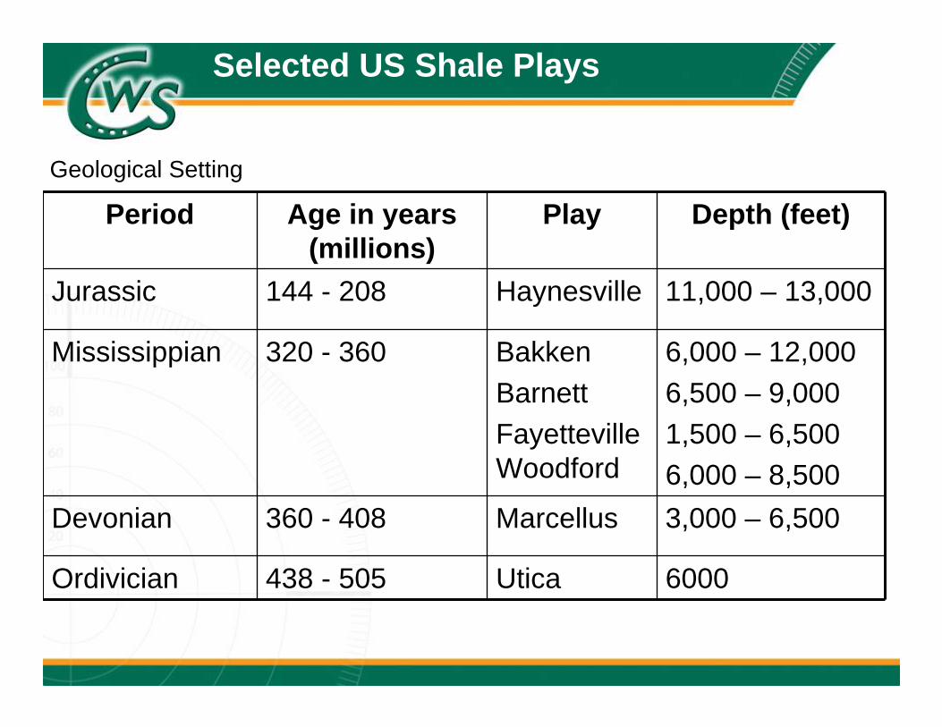
Period Age in years (millions)
Play Depth (feet)
Jurassic 144 - 208 Haynesville 11,000 – 13,000
Mississippian 320 - 360 BakkenBarnettFayetteville Woodford
6,000 – 12,0006,500 – 9,0001,500 – 6,5006,000 – 8,500
Devonian 360 - 408 Marcellus 3,000 – 6,500
Ordivician 438 - 505 Utica 6000
Geological Setting
Selected US Shale Plays
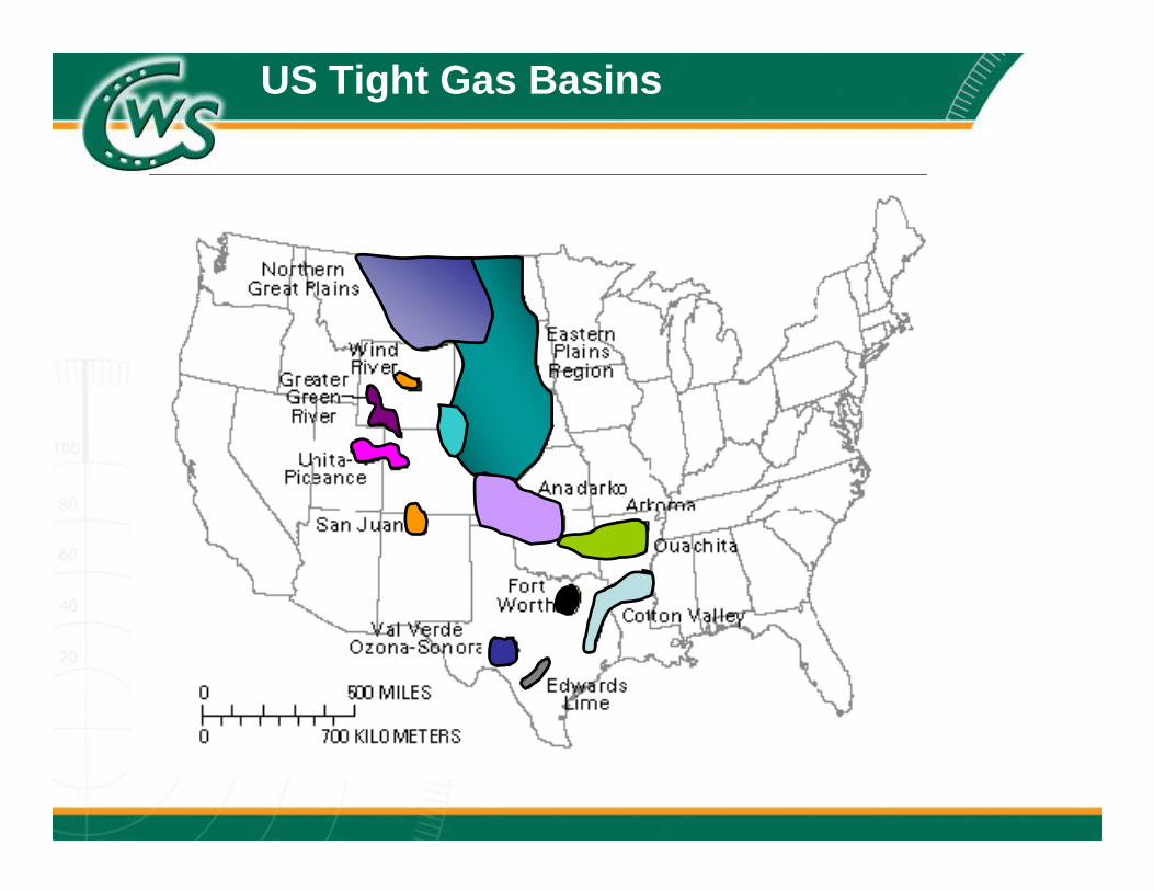
US Tight Gas Basins
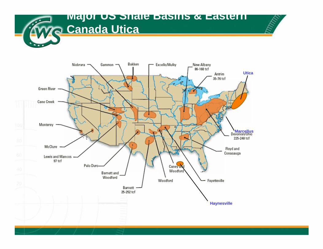
Utica
Marcellus
Haynesville
Major US Shale Basins & Eastern Canada Utica
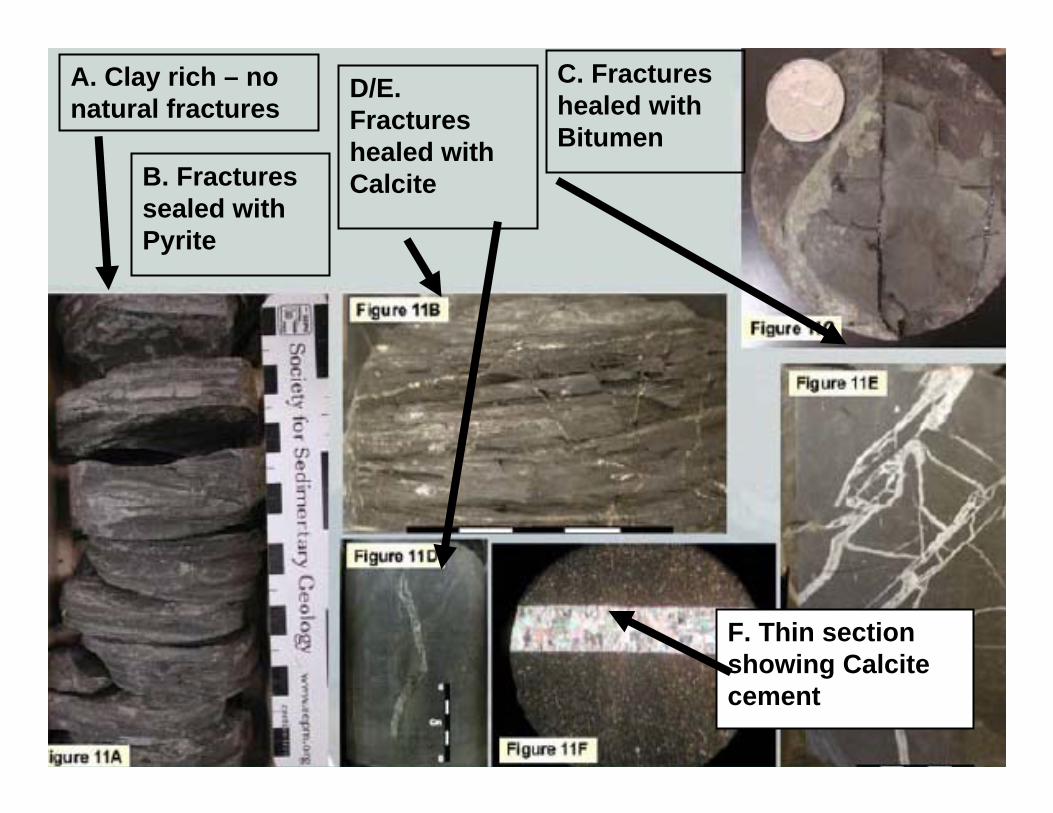
A. Clay rich – no natural fractures
B. Fractures sealed with Pyrite
C. Fractures healed with Bitumen
D/E. Fractures healed with Calcite
F. Thin section showing Calcite cement


Quartz
Clays
Carbonate
0
20
40
60
80
100
percent
20
40
60
80
100
100 80 60 40 20
0
0percent
percent
Influence of Mineralologyon Shale Characteristics
1: Brittle quartz rich2: Brittle carbonate3, 4: Ductile, hard to frac
1
2
3
4
Ternay Diagram

Quartz
Clays
Carbonate
0
20
40
60
80
100
percent
20
40
60
80
100
100 80 60 40 20
0
0percent
percent
1: Brittle quartz rich2: Brittle carbonate3, 4: Ductile, hard to frac
1
2
3
4
Horn River
Influence of Mineralologyon Shale Characteristics
Ternay Diagram

Quartz
Clays
Carbonate
0
20
40
60
80
100
percent
20
40
60
80
100
100 80 60 40 20
0
0percent
percent
1: Brittle quartz rich2: Brittle carbonate3, 4: Ductile, hard to frac
1
2
3
4
Horn RiverFayetteville
Influence of Mineralologyon Shale Characteristics
Ternay Diagram

Quartz
Clays
Carbonate
0
20
40
60
80
100
percent
20
40
60
80
100
100 80 60 40 20
0
0percent
percent
1: Brittle quartz rich2: Brittle carbonate3, 4: Ductile, hard to frac
1
2
3
4
Horn RiverFayettevilleBarnett
Influence of Mineralologyon Shale Characteristics
Ternay Diagram

Quartz
Clays
Carbonate
0
20
40
60
80
100
percent
20
40
60
80
100
100 80 60 40 20
0
0percent
percent
Horn RiverFayettevilleBarnettMontney
Influence of Mineralologyon Shale Characteristics
Ternay Diagram

Petrophysics & Engineering
Petrophysical & Engineering Analysis
Modeling & production simulation GohferTM
MFracTM, Meyer & Assoc. FracProTM
Log interpretation software
Micro seismic data analysis Core properties research

Technological Breakthroughs
3 technological breakthroughs that have changed the industry’s ability to pursue “unconventional” resources:
1. 3D High Resolution Seismic 2. Horizontal Drilling
4,000m TVD
6,000m TMD
3. Hydraulic Fracturing Multi-stage technologies
CWS has performedup to 40 fracs / well

Research & Development
World-class facilities in Calgary, AB and Denver, COto fascilitate major R&D projects Calfrac’s “Green” initiative Flow Loop
Optimize friction reduction Understand chemical interaction Compatibility with recycled water
Complete Cement Lab Other Capabilities
Microbial studies, Proppant analysis, Corrosion work, Scale loop, Core flood testing, FTIR, ICP analysis, Extended water analysis, Acid solubility testing, Photo microscope

New Technologies
CWS-600 Fluid System Ability to use Recycled, Produced or Fresh Water Customizable chemical package High friction reduction characteristics Many components are Calfrac Level 1 Green
SlikProTM Fluid System Treatment design very similar to slick water
Use recycled frac oil instead of water Energized with Liquid CO2, which is totally miscible in oil Spectacular clean-up of fracture fluid
Low chemical loadings reduce potential formation damage High friction reduction characteristics

New Technologies
Water Systems Linear Gel Cross-linked Borate Cross-linked Zirconium CleanTechTM
Hybrid Fluid Designs
Foamed Systems CleanTechTM (N2 and CO2) PolyCO2
Hydrocarbon System DynaGel-H2

Equipment Innovation
Equipment Design
Built-for-purpose equipment High HHP Pumps
Robust components Increased life cycle
Redundancies
New generation blenders Newest technologies and electronics
Multi-pump controls High tech hardware & software

Service Quality Improvement
Recent Advances in Service Quality
>16 hours pumping per day with “fuel-on-the-fly” technology Custom-design wellhead & manifold configurations
Possible Bi-fuel, Natural Gas conversion for pumping equipment Requires strategic partnership for execution
Logistical Advantages
Coordination of Logistics
Procurement of proppant supply is key Long-term contracts with multiple suppliers for redundancy
Sand handling challenges & solutions Utilize numerous delivery points
Maintain flexibility
Chemical supply Newest chemical technologies developed in-house or co-
developed with top-tier providers

Multi-Stage Experience
Completion Technologies
Calfrac has performed >40,000 “conventional” treatments >15,000 treatments using Plug & Perf Method
May also convey tools with Coiled Tubing, Tractors

Multi-Stage Experience
Other Completion Technologies currently utilized:
Open-hole mechanical packers (ball & seat) Open-hole swell packers (ball & seat)
Sliding Sleeves Abrasive-Jetting
Stimulation Techniques Zipper-Fracs
Simo-Fracs
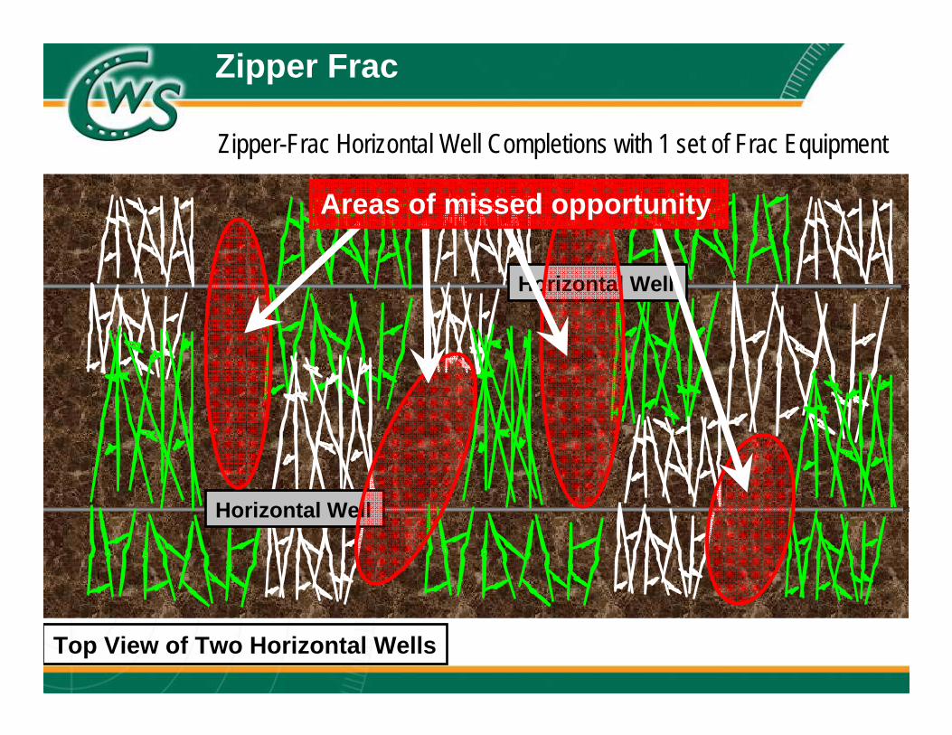
Zipper Frac
Horizontal Well
Horizontal Well
Zipper-Frac Horizontal Well Completions with 1 set of Frac Equipment
Top View of Two Horizontal Wells
Areas of missed opportunity
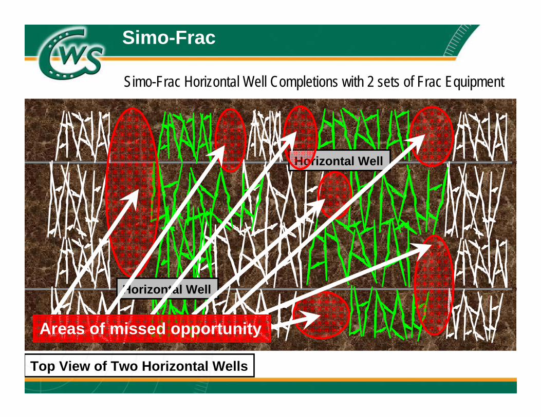
Simo-Frac
Top View of Two Horizontal Wells
Horizontal Well
Horizontal Well
Simo-Frac Horizontal Well Completions with 2 sets of Frac Equipment
Areas of missed opportunity

Simo-Frac
Simo-Frac Horizontal Well Completions with 2 set of Frac Equipment

Industry Challenges
Extensive pre-planning required for large unconventional projects
Supply and storage of large volumes of fluid (water / oil) Many Calfrac fluid systems (CWS-600, SlikProTM) are
compatible with fresh, produced and/or recycled fluids Coordination of well locations to facilitate fracture mapping
Innovation to control costs, achieve operations efficiencies andimprove economies of scale
Ensuring material supply (sand, chemicals, etc)

Dedication to Efficiencies
Other Efficiencies:
Proppant Storage Proppant Plant, Sand Storm Proppant Moving TeleBelt
Operational Summary
Technical expertise for custom-design programs
Almost 1,000,000 HHP worldwide by EOY 2012 State of the art equipment, built for most challenging conditions
Redundant critical components Detailed preventative maintenance programs
Secured supply of materials (proppants, chemicals)
Environmental stewardship, reducing environmental footprint Top-tier logistics coordination
40% of North American fleets operating 24 hours

Personnel
“Attract, recruit and retain the most experienced crews in the industry”
Calfrac provides top-tier training programs, such as:
Orientation and Training School (15 days) New Hire Mentoring Program (90 days) Operator Training, Levels 1-4 Supervisor Training, Levels 1-3 Supervisor Development Program, SAIT Safe Driving Program Maintenance Training Leadership Development Program, Haskayne School of
Business

Collaboration: Horn River Basin
From single zone completions to 40+ day projects, Calfrac has proven the ability execute in the most challenging environments: 24 Frac pumps for 18 m3/min Coiled Tubing crews milling bridge plugs Wireline & pump down operations Wellhead & manifold personnel Water management, testers, flow-back teams Safety / medical / fire response teams as precaution Proppant plant personnel Specialty tool companies Transportation & logistics crews

50
Nexen – Horn River, 2011
CWS Mission Statement

51
Nexen – Horn River, 2011
CWS Mission Statement

52
2,800 tonne Sand Plant for on-site storage and delivery
Benefits: Reliability and redundancy – no downtime Buffer against sand delivery disruptions Belly dump trucks – faster, lower cost, availability Reduced dust and noise No spillage or waste Accurate inventory – built in weigh scales
0.5% error over 30,000 tonne
Sand Handling

53
Nexen – Horn River, 2011
CWS Mission Statement

54
Redundant Blender Set-up
Nexen – Horn River, 2011

55
Safety initiatives and results Innovative crew change resulting in no downtime Slipstream pumping configuration – reduced wear on equipment ERS – automated, self-contained fueling system FMC manifold Sand Plant Remote maintenance facilities Modified mast CTU with side reel
Innovations to date

56
Development of high temperature drill out fluid Customized acid design Chemical Injection Skids, Chemstar, Iron Trucks Optimized friction reducers using CWS flow-loop High TDS tolerant friction reducers (water recycling) Introduction of “green” chemicals
Innovations to date

57
FMC Manifold, Wellhead Assembly

58
Nexen – Horn River, 2011

59
Nexen – Horn River, 2011

Horn River Basin: The Result
ZERO safety incidents for 2010 and 2011
Achieved 3.5 fracs per day for 42-day projects in 2010, 2011
10-20% higher than nearest competitor, at time
More than 16 hours pumping time per day
Exceeded operator expectations by 23 days
Significant cost savings
No job interruptions due to equipment or logistic delays

61
Skid-mounted, high HHP, continuous-duty pumps Skid-mounted, dual-redundancy blenders High volume sand transportation and storage Chemical transportation, storage and injection
Dry FR (transportation, “green”) Larger treating iron Effective year round operation
Horn River Basin: Our Vision
62
“Frac Machine” – The concept of a fit-for-purpose fleet specifically engineered for perpetual operations in the Horn River Basin.
Logistics / supply Blending Pumping Intervention Maintenance Manpower
Horn River Basin: Our Vision

63
High HHP pump-down crews pumping acid spearheads Large capacity CT units for extended-reach applications Bi-fueling alternatives & electrification Testing initiative to improve component life cycles
NDTMA: George Rhodes, Ph.D. – expert on nondestructive methods and defect detection
Horn River Basin: Our Vision

64
Footprint

65
Piping

66
³
³
³
³
³
Process

67
Reduced footprint Pump count reduced by 33%
Improved safety and reduced environmental impact Fewer personnel required, greener technologies
Reduced manpower requirement Target is 40% reduction in personnel
Greater reliability Equipment capable of continuous operation
Concurrent operations Cost efficiency
The Result

68
Long term contracts Simplified billing Quick pay discount Performance and safety incentives
Contract for Success

Our Plan for Argentina
Phase 1 (early Q3 2012): 30,000 HHP and all support equipment to be operational 2 fluid blenders Focus on conventional and unconventional market Slick water & Hybrid frac design primarily
Phase 2 (Q1 2013): Additional 20,000 HHP to arrive Introduce 120 bbl/min blender


Thank you!
For more information on Calfrac Well Services, please visit:www.calfrac.com